Embed Size (px)
Citation preview
Ex d
A.53 ED.2017A.53 ED.2017
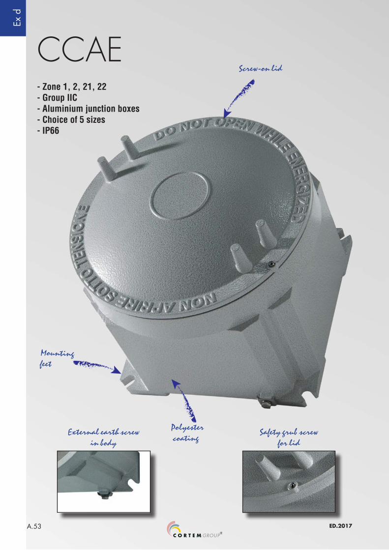
CCAE
Polyester coating
External earth screw in body
Safety grub screw for lid
Mounting feet
- Zone 1, 2, 21, 22- Group IIC- Aluminium junction boxes- Choice of 5 sizes- IP66
Screw-on lid
Ex d
A.54ED.2017
CCA-...E series Aluminium junction boxes gas group IIC
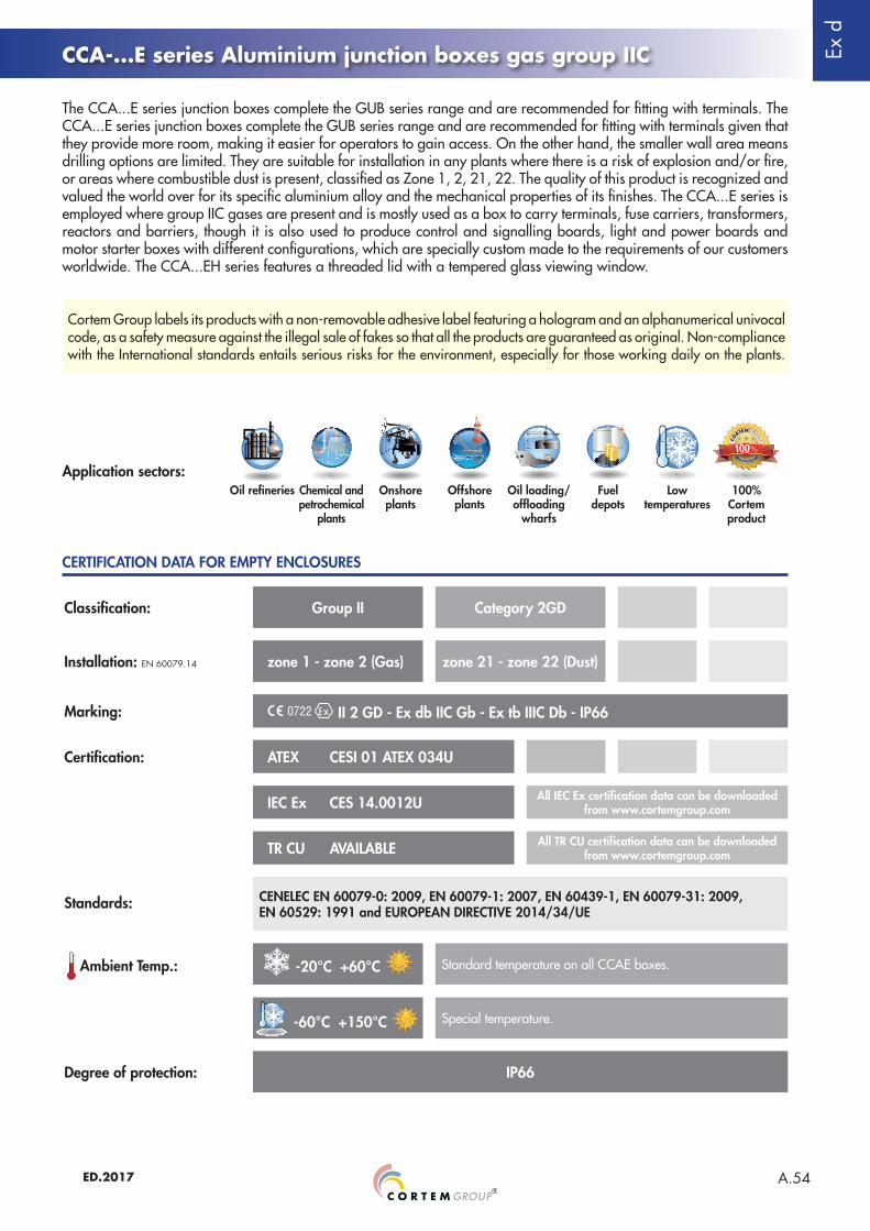
The CCA...E series junction boxes complete the GUB series range and are recommended for fitting with terminals. The CCA...E series junction boxes complete the GUB series range and are recommended for fitting with terminals given that they provide more room, making it easier for operators to gain access. On the other hand, the smaller wall area means drilling options are limited. They are suitable for installation in any plants where there is a risk of explosion and/or fire, or areas where combustible dust is present, classified as Zone 1, 2, 21, 22. The quality of this product is recognized and valued the world over for its specific aluminium alloy and the mechanical properties of its finishes. The CCA...E series is employed where group IIC gases are present and is mostly used as a box to carry terminals, fuse carriers, transformers, reactors and barriers, though it is also used to produce control and signalling boards, light and power boards and motor starter boxes with different configurations, which are specially custom made to the requirements of our customers worldwide. The CCA...EH series features a threaded lid with a tempered glass viewing window.
CERTIFICATION DATA FOR EMPTY ENCLOSURES
Classification: Group II Category 2GD
Installation: EN 60079.14 zone 1 - zone 2 (Gas) zone 21 - zone 22 (Dust)
Marking: II 2 GD - Ex db IIC Gb - Ex tb IIIC Db - IP66
Certification: ATEX CESI 01 ATEX 034U
IEC Ex CES 14.0012U All IEC Ex certification data can be downloaded from www.cortemgroup.com
TR CU AVAILABLE All TR CU certification data can be downloaded from www.cortemgroup.com
Standards: CENELEC EN 60079-0: 2009, EN 60079-1: 2007, EN 60439-1, EN 60079-31: 2009, EN 60529: 1991 and EUROPEAN DIRECTIVE 2014/34/UE
Ambient Temp.: -20°C +60°C Standard temperature on all CCAE boxes.
-60°C +150°C Special temperature.
Degree of protection: IP66
Cortem Group labels its products with a non-removable adhesive label featuring a hologram and an alphanumerical univocal code, as a safety measure against the illegal sale of fakes so that all the products are guaranteed as original. Non-compliance with the International standards entails serious risks for the environment, especially for those working daily on the plants.
Application sectors:Oil refineries Chemical and
petrochemical plants
Onshore plants
Offshore plants
Oil loading/offloading
wharfs
Fuel depots
Low temperatures
100% Cortemproduct

Ex d
A.55 ED.2017
CCA-...E series Aluminium junction boxes gas group IIC
CERTIFICATION DATA FOR ENCLOSURES WITH TERMINALS
Classification: Group II Category 2GD
Installation: EN 60079.14 zone 1 - zone 2 (Gas) zone 21 - zone 22 (Dust)
Marking: II 2 GD - Ex d IIC T6, T5 Gb - Ex tb IIIC T85, T100°C Db - IP66
Certification: ATEX CESI 01 ATEX 035
IEC Ex CES 16.0013X All IEC Ex certification data can be downloaded from www.cortemgroup.com
TR CU AVAILABLE All TR CU certification data can be downloaded from www.cortemgroup.com
Standards: CENELEC EN 60079-0: 2009, EN 60079-1: 2007, EN 60439-1, EN 60079-31: 2009, EN 60529: 1991 and EUROPEAN DIRECTIVE 2014/34/UE
Ambient Temp.: -50°C +40°C With temperature class T6 and maximum surface temperature T85°C.
-50°C +55°C With temperature class T5 and maximum surface temperature T100°C.
Degree of protection: IP66
CERTIFICATION DATA OF ENCLOSURES FOR CONTROL, MONITORING AND SIGNALLING UNITS
Classification: Group II Category 2GD
Installation: EN 60079.14 zone 1 - zone 2 (Gas) zone 21 - zone 22 (Dust)
Marking: II2GD - Ex db IIC T6, T5 Gb - Ex tb IIIC T85°C, T100°C Db - IP66
Certification: ATEX CESI 01 ATEX 036X
IEC Ex CES 16.0013X All IEC Ex certification data can be downloaded from www.cortemgroup.com
TR CU AVAILABLE All TR CU certification data can be downloaded from www.cortemgroup.com
INMETRO DNV 14.0152 All INMETRO certification data can be downloaded from www.cortemgroup.com
Standards: CENELEC EN 60079-0: 2012 + A11: 2013, EN 60079-1: 2014, EN 60079-31: 2014, EN 60529: 1991 and EUROPEAN DIRECTIVE 2014/34/UE
Ambient Temp.: -20°C +40°C With temperature class T6 and maximum surface temperature T85°C.
-20°C +55°C With temperature class T5 and maximum surface temperature T100°C.
-60°C On request.
Degree of protection: IP66
Ex d
A.56ED.2017
CCA-...E series Aluminium junction boxes gas group IIC
CERTIFICATION DATA FOR ENCLOSURES SERVING SURGE ARRESTER FUNCTION
Classification: Group II Category 2GD
Installation: EN 60079.14 zone 1 - zone 2 (Gas) zone 21 - zone 22 (Dust)
Marking: II2GD - Ex db IIC T6, T5 Gb - Ex tb IIIC T85°C, T100°C Db - IP66
Certification: ATEX CESI 01 ATEX 036X
IEC Ex CES 16.0013X All IEC Ex certification data can be downloaded from www.cortemgroup.com
TR CU AVAILABLE All TR CU certification data can be downloaded from www.cortemgroup.com
Standards: CENELEC EN 60079-0: 2012 + A11: 2013, EN 60079-1: 2014, EN 60079-31: 2014, EN 60529: 1991 and EUROPEAN DIRECTIVE 2014/34/UE
Ambient Temp.: -20°C +40°C With temperature class T6 and maximum surface temperature T85°C.
-20°C +55°C With temperature class T5 and maximum surface temperature T100°C.
-60°C On request.
Degree of protection: IP66
CERTIFICATION DATA OF ENCLOSURES SERVING INTERFACE UNIT CONTROL AND MONITORING FUNCTION
Classification: Group II Category 2GD
Installation: EN 60079.14 zone 1 - zone 2 (Gas) zone 21 - zone 22 (Dust)
Marking: II2(1)GD - Ex d [ia Ga] IIC T... Gb - Ex tb [ia Da] IIIC T...°C Db - IP66
Certification: ATEX CESI 03 ATEX 174X
IEC Ex CES 16.0015X Para todos los datos de certificación IEC Ex, descargue el certificado de la página web www.cortemgroup.com
TR CU AVAILABLE All TR CU certification data can be downloaded from www.cortemgroup.com
Standards: CENELEC EN 60079-0: 2009, EN 60079-1: 2007, EN 60079-11: 2007, EN 60079-26: 2007, EN 60079-31: 2009 and EUROPEAN DIRECTIVE 2014/34/UE
Ambient Temp.: -20°C +40°C With temperature class T6 and maximum surface temperature T85°C.
-20°C +55°C With temperature class T5 and maximum surface temperature T100°C.
-60°C On request.
Degree of protection: IP66
Ex d
A.57 ED.2017
ORIGINAL PRODUCT
CCA-...E series Aluminium junction boxes gas group IIC
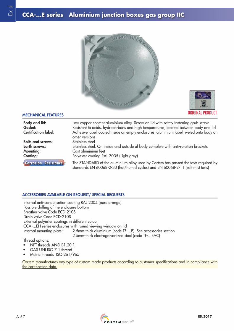
Body and lid: Low copper content aluminium alloy. Screw-on lid with safety fastening grub screwGasket: Resistant to acids, hydrocarbons and high temperatures, located between body and lidCertification label: Adhesive label located inside on empty enclosures; aluminium label riveted onto body on
other versionsBolts and screws: Stainless steelEarth screws: Stainless steel. On inside and outside of body complete with anti-rotation bracketsMounting: Cast aluminium feetCoating: Polyester coating RAL 7035 (Light grey)
: The STANDARD of the aluminium alloy used by Cortem has passed the tests required by standards EN 60068-2-30 (hot/humid cycles) and EN 60068-2-11 (salt mist tests)
Internal anti-condensation coating RAL 2004 (pure orange)Possible drilling of the enclosure bottom Breather valve Code ECD-210SDrain valve Code ECD-210SExternal polyester coatings in different colourCCA-...EH series enclosures with round viewing window on lidInternal mounting plate: 2.5mm-thick aluminium (code TF-...E). See accessories section 2.5mm-thick electrogalvanized steel (code TF-...EAC)Thread options:• NPT threads ANSI B1.20.1• GAS UNI ISO 7-1 thread• Metric threads ISO 261/965
MECHANICAL FEATURES
ACCESSORIES AVAILABLE ON REQUEST/ SPECIAL REQUESTS
Cortem manufactures any type of custom-made products according to customer specifications and in compliance with the certification data.

Ex d
A.58ED.2017
CCA-0E 128 128 146 133 104 104 75 130x2 12 111 138 9
CCA-01E 145 145 170 135 121 121 75 150x2 12 128 150 9
CCA-02E 195 195 220 159 171 171 83 200x3 12 175 175 10
CCA-03E 240 240 270 230 216 216 140 250x3 12 213 213 12
CCA-04E 385 385 410 294 353 353 156 390x3 16 339 339 14
CCA-...E series Aluminium junction boxes gas group IIC
Code Outside dimensions Inside dimensions Mounting WeightA B ØB1 C a b c Ød1 s E F ØG kg
DIMENSIONAL DRAWING
ENCLOSURE SELECTION CHART
2 feet for CCA-0E, CCA-01E4 feet for CCA-02E, CCA-03E and CCA-04E
Cross-section C - C
Dimensions in mm
Ex d
A.59 ED.2017
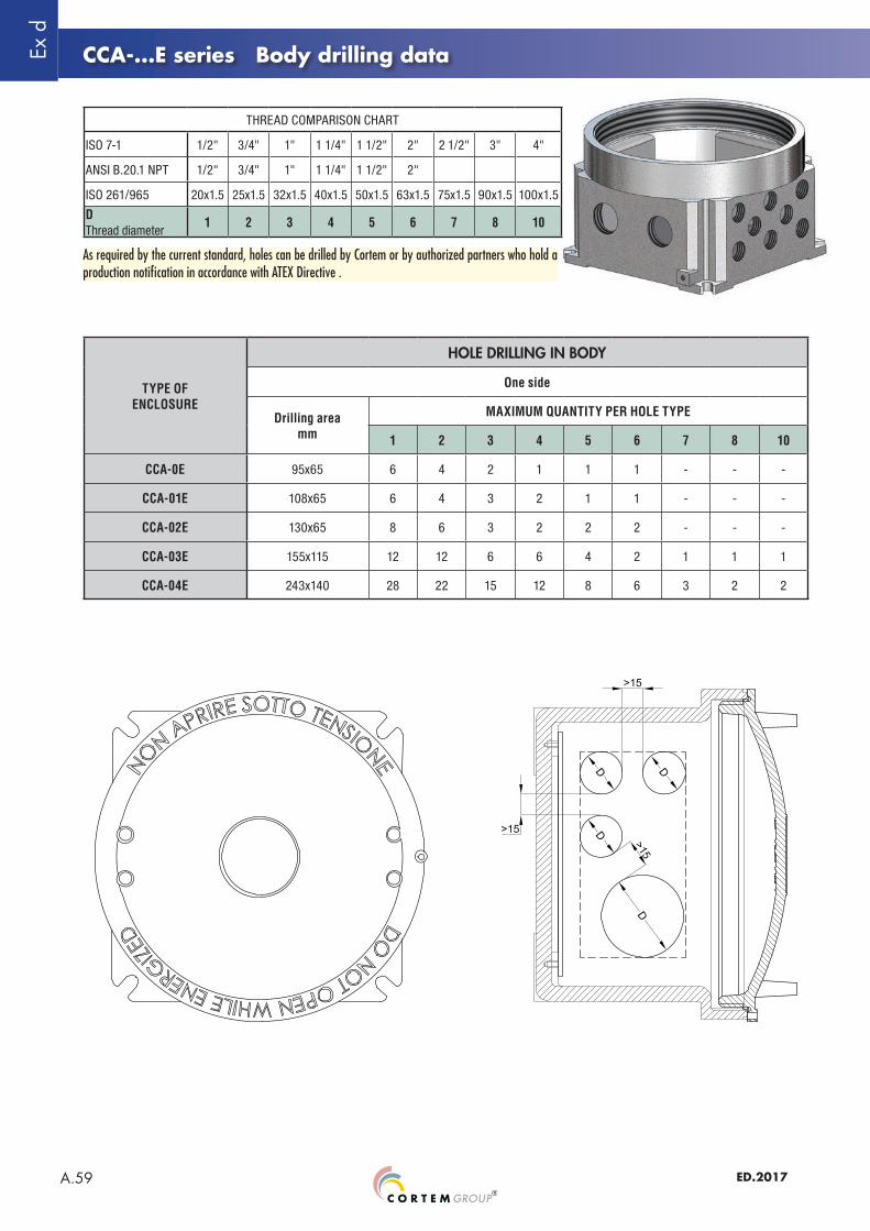
CCA-...E series Body drilling data
THREAD COMPARISON CHART
ISO 7-1 1/2" 3/4" 1" 1 1/4" 1 1/2" 2" 2 1/2" 3" 4"
ANSI B.20.1 NPT 1/2" 3/4" 1" 1 1/4" 1 1/2" 2"
ISO 261/965 20x1.5 25x1.5 32x1.5 40x1.5 50x1.5 63x1.5 75x1.5 90x1.5 100x1.5
D Thread diameter
1 2 3 4 5 6 7 8 10
TYPE OFENCLOSURE
HOLE DRILLING IN BODY
One side
Drilling areamm
MAXIMUM QUANTITY PER HOLE TYPE
1 2 3 4 5 6 7 8 10
CCA-0E 95x65 6 4 2 1 1 1 - - -
CCA-01E 108x65 6 4 3 2 1 1 - - -
CCA-02E 130x65 8 6 3 2 2 2 - - -
CCA-03E 155x115 12 12 6 6 4 2 1 1 1
CCA-04E 243x140 28 22 15 12 8 6 3 2 2
As required by the current standard, holes can be drilled by Cortem or by authorized partners who hold a production notification in accordance with ATEX Directive .
Ex d
A.60ED.2017
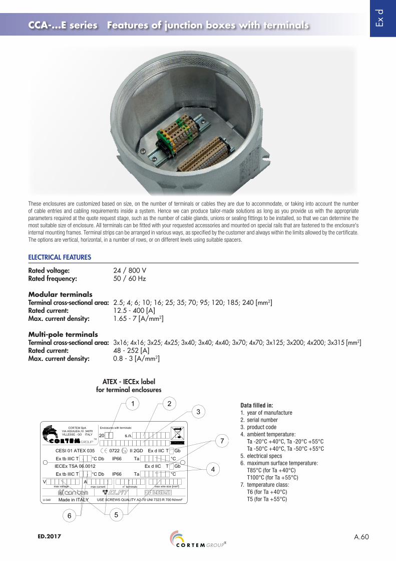
CCA-...E series Features of junction boxes with terminals
Rated voltage: 24 / 800 VRated frequency: 50 / 60 Hz
Modular terminalsTerminal cross-sectional area: 2.5; 4; 6; 10; 16; 25; 35; 70; 95; 120; 185; 240 [mm2]Rated current: 12.5 - 400 [A]Max. current density: 1.65 - 7 [A/mm2]
Multi-pole terminalsTerminal cross-sectional area: 3x16; 4x16; 3x25; 4x25; 3x40; 3x40; 4x40; 3x70; 4x70; 3x125; 3x200; 4x200; 3x315 [mm2]Rated current: 48 - 252 [A]Max. current density: 0.8 - 3 [A/mm2]
ELECTRICAL FEATURES
ATEX - IECEx label for terminal enclosures
Data filled in:1. year of manufacture2. serial number3. product code4. ambient temperature: Ta -20°C +40°C, Ta -20°C +55°C Ta -50°C +40°C, Ta -50°C +55°C5. electrical specs6. maximum surface temperature: T85°C (for Ta +40°C) T100°C (for Ta +55°C)7. temperature class: T6 (for Ta +40°C) T5 (for Ta +55°C)
These enclosures are customized based on size, on the number of terminals or cables they are due to accommodate, or taking into account the number of cable entries and cabling requirements inside a system. Hence we can produce tailor-made solutions as long as you provide us with the appropriate parameters required at the quote request stage, such as the number of cable glands, unions or sealing fittings to be installed, so that we can determine the most suitable size of enclosure. All terminals can be fitted with your requested accessories and mounted on special rails that are fastened to the enclosure's internal mounting frames. Terminal strips can be arranged in various ways, as specified by the customer and always within the limits allowed by the certificate. The options are vertical, horizontal, in a number of rows, or on different levels using suitable spacers.

Ex d
A.61 ED.2017
CCA-...E series Features of junction boxes with terminals
TYPE OFENCLOSURE
MAXIMUM NUMBER OF TERMINALS HOUSED
TERMINAL CROSS-SECTIONAL AREA
2.5 4 6 10 16 35 70 120 185
CCA-0E 13 12 8 7 6 - - - -
CCA-01E 17 14 11 9 7 5 - - -
CCA-02E 2x22 2x19 2x15 2x12 2x10 6 - - -
CCA-03E 2x32 2x27 2x22 2x17 2x14 8 - - -
CCA-04E 3x40 3x30 2x28 2x23 2x18 12 10 6 4
Examples of terminal strips with minimum installation distances
Eg. 2x22= 2 rows of 22 terminals (total 44 terminals). The maximum number of standard terminals refers to the mounting of CABUR terminals
Ex d
A.62ED.2017
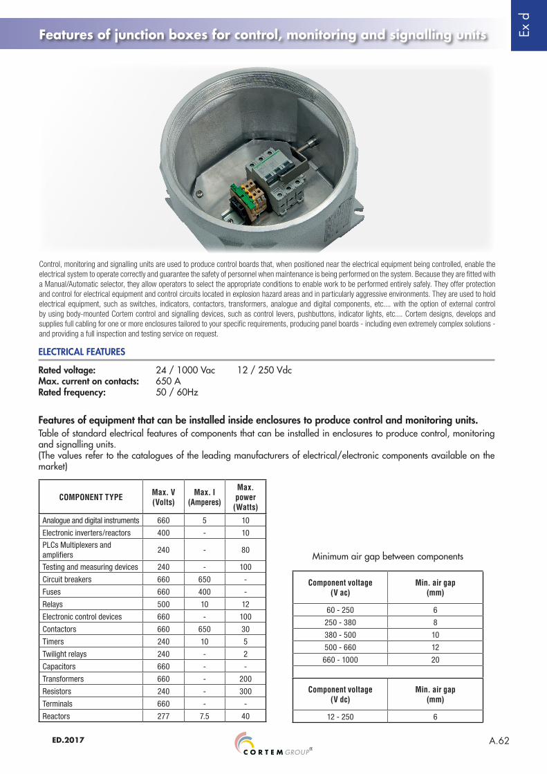
Features of junction boxes for control, monitoring and signalling units
Rated voltage: 24 / 1000 Vac 12 / 250 VdcMax. current on contacts: 650 ARated frequency: 50 / 60Hz
ELECTRICAL FEATURES
COMPONENT TYPE Max. V(Volts)
Max. I(Amperes)
Max. power
(Watts)
Analogue and digital instruments 660 5 10
Electronic inverters/reactors 400 - 10
PLCs Multiplexers and amplifiers
240 - 80
Testing and measuring devices 240 - 100
Circuit breakers 660 650 -
Fuses 660 400 -
Relays 500 10 12
Electronic control devices 660 - 100
Contactors 660 650 30
Timers 240 10 5
Twilight relays 240 - 2
Capacitors 660 - -
Transformers 660 - 200
Resistors 240 - 300
Terminals 660 - -
Reactors 277 7.5 40
Features of equipment that can be installed inside enclosures to produce control and monitoring units.Table of standard electrical features of components that can be installed in enclosures to produce control, monitoring and signalling units.(The values refer to the catalogues of the leading manufacturers of electrical/electronic components available on the market)
Minimum air gap between components
Component voltage(V ac)
Min. air gap(mm)
60 - 250 6
250 - 380 8
380 - 500 10
500 - 660 12
660 - 1000 20
Component voltage(V dc)
Min. air gap(mm)
12 - 250 6
Control, monitoring and signalling units are used to produce control boards that, when positioned near the electrical equipment being controlled, enable the electrical system to operate correctly and guarantee the safety of personnel when maintenance is being performed on the system. Because they are fitted with a Manual/Automatic selector, they allow operators to select the appropriate conditions to enable work to be performed entirely safely. They offer protection and control for electrical equipment and control circuits located in explosion hazard areas and in particularly aggressive environments. They are used to hold electrical equipment, such as switches, indicators, contactors, transformers, analogue and digital components, etc.... with the option of external control by using body-mounted Cortem control and signalling devices, such as control levers, pushbuttons, indicator lights, etc.... Cortem designs, develops and supplies full cabling for one or more enclosures tailored to your specific requirements, producing panel boards - including even extremely complex solutions - and providing a full inspection and testing service on request.
Ex d
A.63 ED.2017
Features of junction boxes for control, monitoring and signalling units
Identification and description of special equipment that is suitable for installation inside.
Enclosures with batteriesOption of installing low-capacity batteries ≤1.5Ah, for powering small electronic devices or backup memories.Whatever the case, the minimum distance of 20mm between the components installed and the inside walls of the enclosure must be met.
Enclosures with surge arrestersOption of installing PRD or similar types of surge arresters, with a maximum protection limit of 65kA; whatever the case, the minimum distance of 20 mm between the arrester and the inside walls of the enclosure must be met.
Enclosures with fibre-optic cablesThe enclosures have provision for feeding multiple (not single) fibre-optic cables in and out. The permitted optical power and radiation limits for optical cables are:- 35mW and 5mW/m2 for T4 temperature class- 15mW and 5mW/m2 for T6 temperature class
Enclosures with radio-frequency sourcesOption of installing components with radio-frequency sources in the 9kHz to 60GHz range that can be used for continuous and pulsed transmission of signals. Antennas can be installed inside or outside the enclosure and must:- comply with one of the protection types indicated in standard EN 60079-0- be installed outside the hazardous area.
For more information, refer to certificate CESI 01 ATEX 036X.
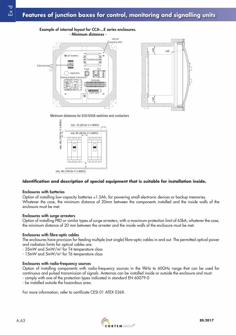
Example of internal layout for CCA-...E series enclosures.- Minimum distances -
Circuit breakers
Transformers
Capacitors
Fuses PLC
TerminalsAnalogue/digital instruments
Earth bars
Internal mounting plate
Minimum distances for 630/650A switches and contactors
External lever
Ex d
A.64ED.2017
Features of junction boxes for control, monitoring and signalling units
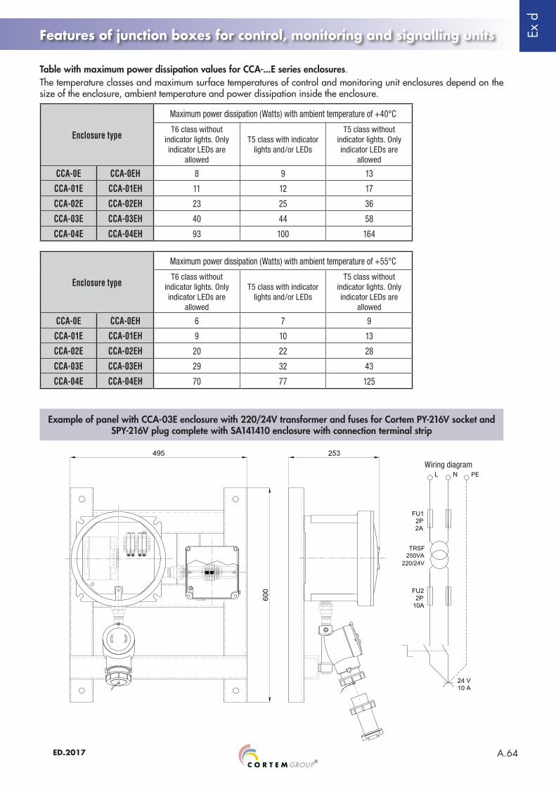
Table with maximum power dissipation values for CCA-...E series enclosures.The temperature classes and maximum surface temperatures of control and monitoring unit enclosures depend on the size of the enclosure, ambient temperature and power dissipation inside the enclosure.
Enclosure type
Maximum power dissipation (Watts) with ambient temperature of +40°C
T6 class without indicator lights. Only indicator LEDs are
allowed
T5 class with indicator lights and/or LEDs
T5 class without indicator lights. Only indicator LEDs are
allowed
CCA-0E CCA-0EH 8 9 13
CCA-01E CCA-01EH 11 12 17
CCA-02E CCA-02EH 23 25 36
CCA-03E CCA-03EH 40 44 58
CCA-04E CCA-04EH 93 100 164
Example of panel with CCA-03E enclosure with 220/24V transformer and fuses for Cortem PY-216V socket and SPY-216V plug complete with SA141410 enclosure with connection terminal strip
Enclosure type
Maximum power dissipation (Watts) with ambient temperature of +55°C
T6 class without indicator lights. Only indicator LEDs are
allowed
T5 class with indicator lights and/or LEDs
T5 class without indicator lights. Only indicator LEDs are
allowed
CCA-0E CCA-0EH 6 7 9
CCA-01E CCA-01EH 9 10 13
CCA-02E CCA-02EH 20 22 28
CCA-03E CCA-03EH 29 32 43
CCA-04E CCA-04EH 70 77 125
Wiring diagram

Ex d
A.65 ED.2017
CCA-...E series Features of junction boxes with interface units
Rated voltage: 24 / 1000 Vac 12 / 250 VdcMax. current oncontacts and fuses: 400 ARated frequency: 50 / 60Hz
ELECTRICAL FEATURES
The maximum power dissipation inside the enclosure depends on the maximum current on contacts and fuses, the size of the enclosure, the temperature class (or maximum surface temperature for 2GD category) and ambient temperature, as specified in the maximum power dissipation tables (see previous page).The maximum power dissipation must not exceed the values given in the table when non-'Ex i' components and 'Ex i' components (with 1.1W maximum power dissipation) are installed together.The maximum power dissipation possible inside the enclosure will also depend on the maximum power dissipation of terminals, contacts and cables; whatever the case, the current density value allowed in the enclosure is prescribed by EN 60439-1, IEC 60439-1.
Details of barrier mounting inside enclosuresThe "omega" rail, in accordance with EN 60079-11, is suitable for mounting barriers inside 'Ex d' enclosures.Barriers are mounted (according to the manufacturer's directions) 7.5 mm away from the base of the enclosure and are secured to the DIN rail with 2 earth terminals (nominal cross-sectional area 6-10 mm) and 2 standard terminals for omega rails (EN 60079-11).Up to how many barriers can be installed in the enclosures will depend on the properties of the barriers in question; in addition, the maximum number of barriers must not exceed the limit allowed by the certificate in any case.
Associated equipment can also be mounted on a DIN rail; when it is mounted on the enclosure's internal mounting plate, reference must be made to the minimum prescribed distances. Whether mounted on a rail or mounting plate, associated equipment must meet the following requirements:SeparatorsWhen separators are used, they must be appropriately sized; their thickness and fastening inside the enclosure must be suitably determined and separators must allow air to circulate inside the enclosure.Incoming cablesIncoming cables for 'Ex i' circuits must be suitably labelled or the area around the entry must be coloured blue RAL 5015. 'Ex i' entries must be clearly identified.Installation of 'Ex i' and non-'Ex i' components inside the enclosure.Ex d IIC certified enclosures complete with accessories can contain only Ex ia IIC associated equipment. In this case, the resulting version becomes Ex d [ia] IIC.Connection of internal cablesCables are connected inside the enclosure to the barriers in accordance with EN 60079-11, with one side for connecting 'Ex i' cables and the opposite side for connecting non-'Ex i' cables.Connection in 'Ex i' circuits must be made using insulated cables only; there must be no connections to non-'Ex i' circuits and no more than one cable can be connected to a single terminal. 'Ex i' cables cannot be grouped together with non-'Ex i' cables. In addition, 'Ex i' cables and non-'Ex i' cables must be kept separate. The minimum distance between the 2 types of cables must be 8 mm. The minimum insulation level for non-'Ex i' cables must be greater than 1.5 kV; the minimum insulation level for 'Ex i' cables must be greater than 0.5 kV.Internal connectionsWhen routing cables belonging to 'Ex i' circuits, the cables must be identified in one of the following ways:• cables must have blue insulation (as long as there are no other cables inside the enclosure with this colour).• 'Ex i' cables must be kept separate from non-'Ex i' cables with blue cable raceways.• 'Ex i' cables must be grouped together, using a tie, for example, and the area identified with a blue label.
Warning 'Ex i' circuits
• cables for power circuits must have a cross-sectional area of at least 1.5 mm2.• 'Ex i' circuits must be kept at a distance of 50 mm from non-'Ex i' circuits.• the earth connection must meet European standard EN 60079-14.
GENERAL INSTALLATION INFORMATION
Ex d
A.66ED.2017
Ex i
Ex i
Ex i
Ex i
CCA-...E series Features of junction boxes with interface units
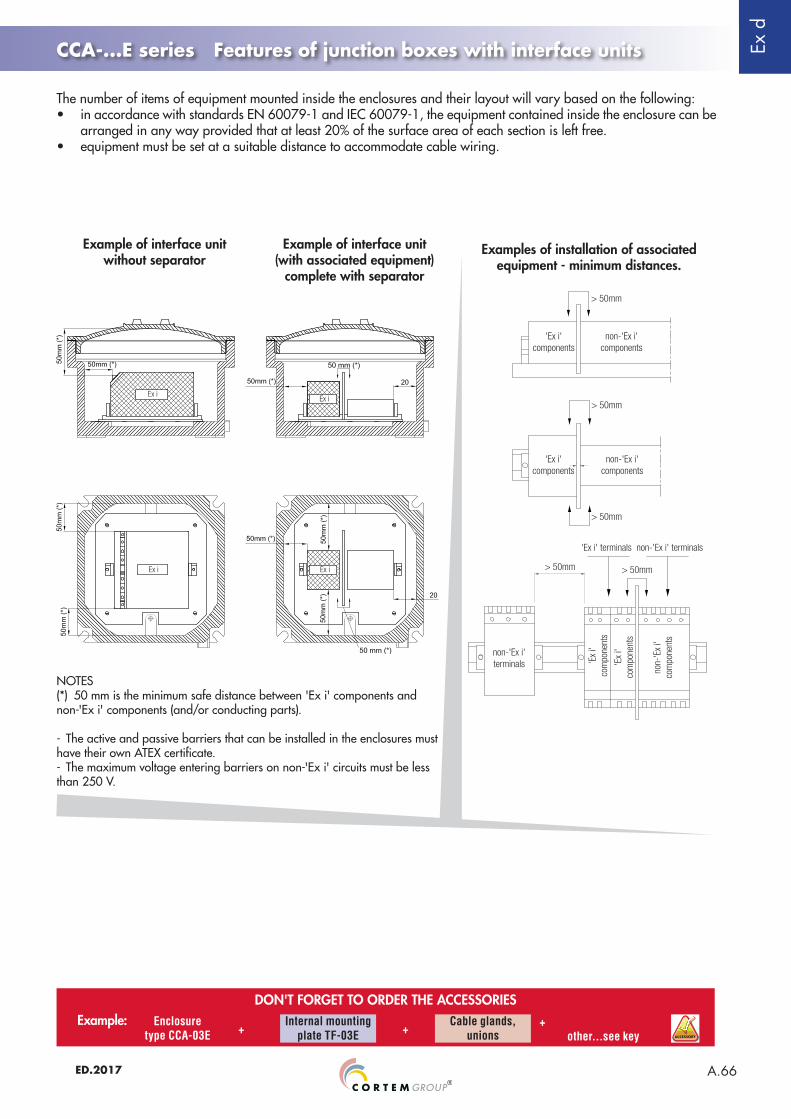
The number of items of equipment mounted inside the enclosures and their layout will vary based on the following:• in accordance with standards EN 60079-1 and IEC 60079-1, the equipment contained inside the enclosure can be
arranged in any way provided that at least 20% of the surface area of each section is left free.• equipment must be set at a suitable distance to accommodate cable wiring.
Examples of installation of associated equipment - minimum distances.
> 50mm
> 50mm
> 50mm
> 50mm > 50mm
'Ex i' components
non-'Ex i' components
non-'Ex i' components
non-'Ex i' terminals
'Ex i' terminals non-'Ex i' terminals
'Ex
i' co
mpo
nent
s
'Ex
i' co
mpo
nent
s
non-
'Ex
i' co
mpo
nent
s
'Ex i' components
Example of interface unitwithout separator
Example of interface unit (with associated equipment)
complete with separator
NOTES(*) 50 mm is the minimum safe distance between 'Ex i' components and non-'Ex i' components (and/or conducting parts).
- The active and passive barriers that can be installed in the enclosures must have their own ATEX certificate.- The maximum voltage entering barriers on non-'Ex i' circuits must be less than 250 V.
DON'T FORGET TO ORDER THE ACCESSORIESExample: Enclosure
type CCA-03E +Internal mounting
plate TF-03ECable glands,
unions+ + other...see key
SPARE PART
ACCESSORY
Ex d
A.67 ED.2017
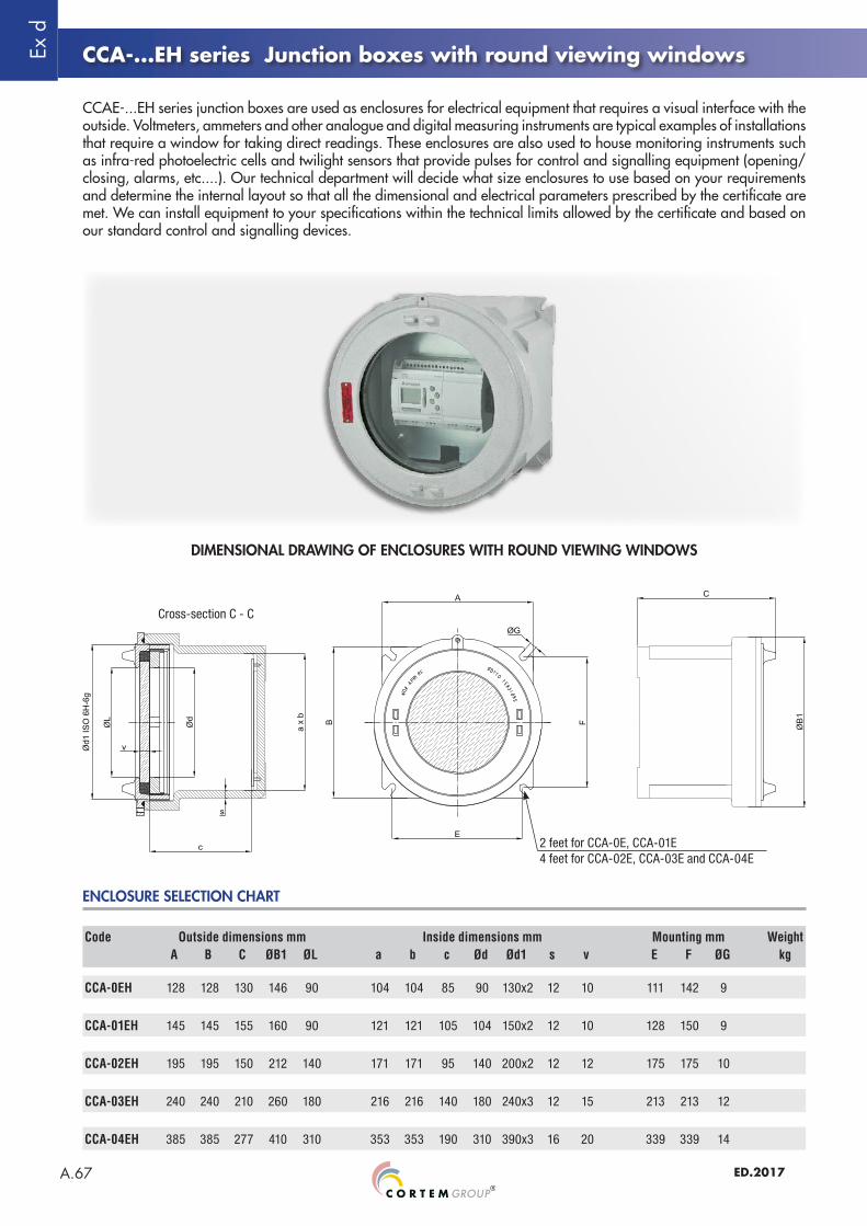
CCA-0EH 128 128 130 146 90 104 104 85 90 130x2 12 10 111 142 9
CCA-01EH 145 145 155 160 90 121 121 105 104 150x2 12 10 128 150 9
CCA-02EH 195 195 150 212 140 171 171 95 140 200x2 12 12 175 175 10
CCA-03EH 240 240 210 260 180 216 216 140 180 240x3 12 15 213 213 12
CCA-04EH 385 385 277 410 310 353 353 190 310 390x3 16 20 339 339 14
CCA-...EH series Junction boxes with round viewing windows
DIMENSIONAL DRAWING OF ENCLOSURES WITH ROUND VIEWING WINDOWS
2 feet for CCA-0E, CCA-01E4 feet for CCA-02E, CCA-03E and CCA-04E
Cross-section C - C
Code Outside dimensions mm Inside dimensions mm Mounting mm WeightA B C ØB1 ØL a b c Ød Ød1 s v E F ØG kg
ENCLOSURE SELECTION CHART
CCAE-...EH series junction boxes are used as enclosures for electrical equipment that requires a visual interface with the outside. Voltmeters, ammeters and other analogue and digital measuring instruments are typical examples of installations that require a window for taking direct readings. These enclosures are also used to house monitoring instruments such as infra-red photoelectric cells and twilight sensors that provide pulses for control and signalling equipment (opening/closing, alarms, etc....). Our technical department will decide what size enclosures to use based on your requirements and determine the internal layout so that all the dimensional and electrical parameters prescribed by the certificate are met. We can install equipment to your specifications within the technical limits allowed by the certificate and based on our standard control and signalling devices.
Ex d
A.68ED.2017
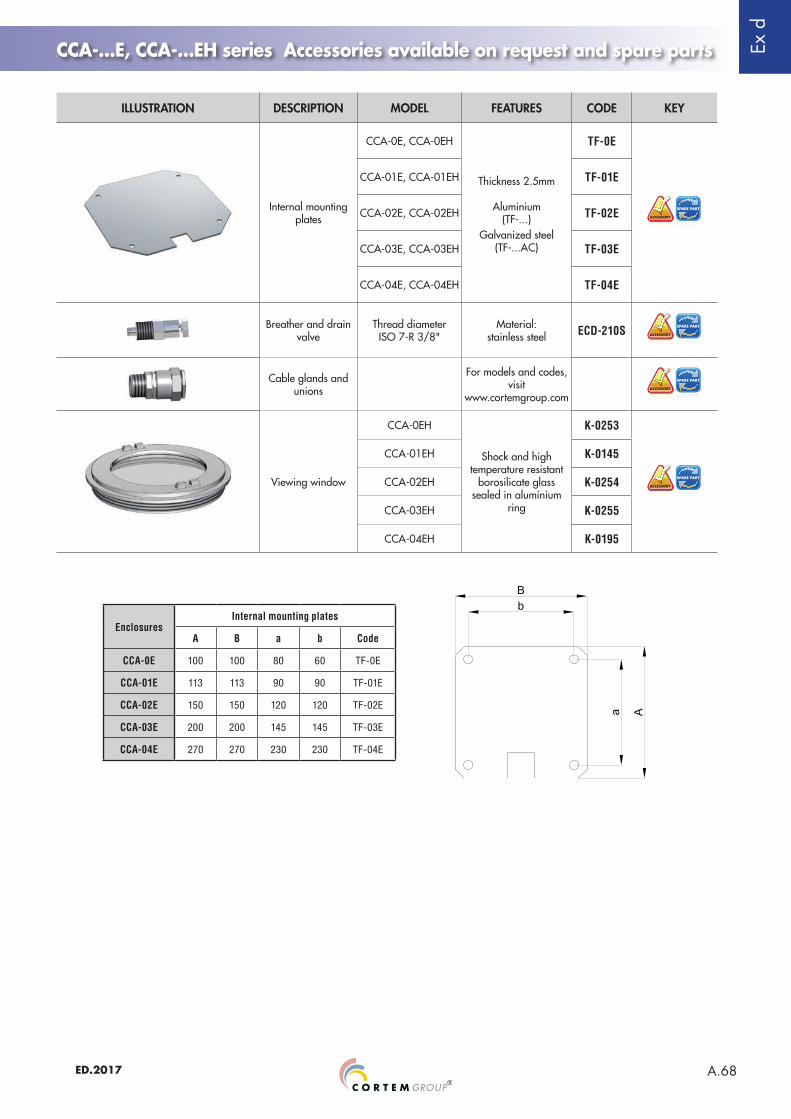
CCA-...E, CCA-...EH series Accessories available on request and spare parts
ILLUSTRATION DESCRIPTION MODEL FEATURES CODE KEY
Internal mounting plates
CCA-0E, CCA-0EH
Thickness 2.5mm
Aluminium(TF-...)
Galvanized steel (TF-...AC)
TF-0E
SPARE PART
ACCESSORY
CCA-01E, CCA-01EH TF-01E
CCA-02E, CCA-02EH TF-02E
CCA-03E, CCA-03EH TF-03E
CCA-04E, CCA-04EH TF-04E
Breather and drain valve
Thread diameterISO 7-R 3/8"
Material:stainless steel ECD-210S SPARE PART
ACCESSORY
Cable glands and unions
For models and codes, visit
www.cortemgroup.com
SPARE PART
ACCESSORY
Viewing window
CCA-0EH
Shock and high temperature resistant
borosilicate glass sealed in aluminium
ring
K-0253
SPARE PART
ACCESSORY
CCA-01EH K-0145
CCA-02EH K-0254
CCA-03EH K-0255
CCA-04EH K-0195
EnclosuresInternal mounting plates
A B a b Code
CCA-0E 100 100 80 60 TF-0E
CCA-01E 113 113 90 90 TF-01E
CCA-02E 150 150 120 120 TF-02E
CCA-03E 200 200 145 145 TF-03E
CCA-04E 270 270 230 230 TF-04E