Embed Size (px)
Citation preview

EVS24Stavanger, Norway, May 13 - 16, 2009
Design of an e-bike with UltraCaps as the only energy sourceand with regenerative braking
Jan Cappelle1, Niels Polfliet1,Michiel Jacxsens1,Jean-Marc Timmermans2
1Jan Cappelle, KaHo Sint-Lieven, gebr. Desmetstraat 1 9000 Ghent, Belgium, [email protected] Universiteit Brussel, Pleinlaan 2, 1050 Brussel, Belgium
Abstract
The number of charge/discharge cycles that can be achieved by today’s ultracapacitors is almost 1000times higher than that of classical batteries. From research [1] that was earlier performed by the VrijeUniversiteit Brussel it is also known that many e-bike users experience the limited battery lifetime asa problem. These 2 facts lead to the design and building of an e-bike without batteries and only usingUltraCaps as energy source. By using a newbuilt split-PI converter topology regenerative braking wasenabled, and its influence on the range of the e-bike could be investigated. The e-bike is controlled by atwist-grip and all electric quantities can be visualised on a touchscreen. The paper describes the designand shows the first test results of an e-bike with a 250W hub motor and a 500F , 16, 2V UltraCap module.In the near future, the e-bike will be used as a didactic demo model to analyze power flow during cycling.
bicycle, regenerative braking, wheel hub motor, DC-DC
1 Why an e-bike with UltraCapsonly?
In most cases, UltraCaps are rightly used as peakpower units. In spite of the low energy density(about ten times less than batteries [2]) it wasconsidered to be an interesting exercise to replacethe battery of an e-bike with UltraCaps only. Thiscould deliver us from the limited battery lifetimeof many of todays e-bikes, and enables very fastcharging. But above all, the e-bike is designedto give students an interesting tool to analyze hu-man and motor power in a familiar way. Withthe straightforward relation between their left-over energy and leftover voltage (expression 1)UltraCaps seem to perfectly suit that goal.
E(V ) =CV 2
2(1)
The use of UltraCaps as the only energy sourceimplies two important problems:
• The limited energy density of UltraCapsmay lead to an even heavier e-bike, while
the user’s feedback always bring the over-weight as the most important disadvantageof e-bikes [3].
• The relationship between the leftover en-ergy in and the voltage over the UltraCaps(expression 1) results in a variable voltagesupply for the motor. This problem can besolved by introducing the right power elec-tronic conversion. This will be discussed indetail in section 2.1.2.
The design of the e-bike should show
• whether or not UltraCaps are appropriate tobe used as the only energy source for themotor of an e-bike
• that it is possible to build a sofisticatedcontrol system for an e-bike with low costpower electronics
• what charge/discharge efficiencies are prac-tically feasible and what advantages are as-sociated with the use of regenerative brakes.
The idea of using a power source of such alimited energy capacity as the applied UltraCap
EVS24 International Battery, Hybrid and Fuel Cell Electric Vehicle Symposium 1

Figure 1: average daily covered distances of 244 testpersons [3]
module is maybe not so stupid is it seems at firstsight. Fig. 1 shows that the daily covered dis-tance with an e-bike for 244 test persons was lessthan 6km for almost half of the test persons. Fig.2 shows a recorded 1 hour during commutercy-cle covered with a conventional bike. The en-ergy required to cover this cycle was calculatedto be only 52Wh. With the energy of the Ultra-Cap module (see expression 2) it is theoreticallypossible to cover one third of this commutercyclein motor-only operation.
Figure 2: One hour recorded commuter speed cyclecovered with a conventional bicycle [4]
Emax =CV 2
max
2= 18, 2Wh (2)
Imagine having loaded the UltraCaps at home,many commuters should get at work while usingthe e-bike as pedelec. With the regenerativebraking it would even be possible to use thee-bike as a fitness bike. User-controlled chargingof the UltraCaps while cycling, increases theresistance, and so increases the effort of thecyclist to every possible level.
2 The e-bike concept
Figure 3: Schematic diagram
An electric bicycle basically has two powersources: the human power from the cyclistand some extra motor power. In opposite to apedelec, the relation between motor and humanpower for an e-bike is not fixed, but is controlledby the cyclist. In this design the cyclist controlsthe motor power by a twist-grip. The motor isa Heinzmann front wheel hub motor of 250W ,with rated voltage of 24V . The energy forthe motor comes from the earlier describedUltraCap module.
Figure 3 shows that the connection between themotor and UltraCaps is realised by a split-PIDC-DC converter (section 2.1.2). To maximizeflexibility, the split-PI drive (section 2.1) can becontrolled by a second embedded system, whichis called the visualisation and data loggingunit (section 2.2), as well as by a PC (section2.3), all trough the same RS-485 Fieldbus [5].During normal operation on the road the datalogging unit receives an analog setpoint for thesplit-PI converter by the twist-grip. When beingcontrolled by a separate emdebbed system, a PCcan also be connected to the RS-485 fieldbus todisplay all variables in real time. This might beinteresting during lab excercises.
It is obvious that the UltraCaps are preferablypreloaded at departure. Since the maximumvoltage of the UltraCaps may not be exceededwhile charging, and since charging on a regular
EVS24 International Battery, Hybrid and Fuel Cell Electric Vehicle Symposium 2

lab power supply is slow, difficult and not foolproof, a dedicated fast charger for the Ultracapmodule was also developed. This charger canfully automatically charge the Ultracap modulefrom empty state to its maximum voltage in lessthen 5 minutes.
Also three separate switching power supplieswith different output voltages were built toprovide a stable autonomous power source forall electronics on the e-bike. For these additionallow power converters the SEPIC (single endedprimary inductor converter) topology was used[6]. The SEPIC topology is distinguished by thefact that its input voltage range can overlap theoutput voltage[7]. This was necessary to providea stable output voltage when the voltage of theUltraCap is above and below the output voltageof the individual converters.
With this configuration, a very flexible systemhas been obtained: The fact that the drive re-cieves its setpoints from another embedded sys-tem or PC even enables the motor drive to beused for a number of other applications then thee-bike including MPP tracking for solar arrays,charging batteries or controlling any type of DCmotor.
2.1 The motor drive
2.1.1 Requirements for the motor driveThe relationship between the leftover energyand the voltage over the UltraCaps (expression1) poses an extra challenge when designingpower electronics for an UltraCap e-bike. TheUltraCap module is specified as a 16.2V , 500Fmodule. The hub motor used, however, reachesits nominal speed at a back EMF of 24V .Using a motor with lower back EMF or using ahigher voltage UltraCap bank only solves partof the problem: the voltage drops quickly overthe UltraCap bank, and the deeper the powerelectronics allow the UltraCap to discharge, themore energy can be drawn from the UltraCapbank. In this context it is worth mentioning that75% of the energy is found in the reduction ofthe UltraCap voltage from Vmax to Vmax/2.
Figure 4: Topology of a classic boost converter
Since the motor has to be able to run at nominalspeed during the whole discharge cycle, a boost
converter (see Fig. 4) is required to boost upthe UltraCap voltage to 24V , no matter whatthe voltage of the UltraCap module is. Practicallower limits of the minimum boostable voltagesat given power levels are imposed to preventhigh currents.
Figure 5: Topology of a classic buck converter
However, to control the motor speed, the voltageof the motor should be controlled, which alsoimplies the use of a buck converter (see Fig. 5).
Variable regenerative braking when the motorsback EMF voltage E is higher then the UltraCapvoltage Vc implies the use of a buck converterin the opposite direction. Variable regenerativebraking when E < Vc implies the use of a secondboost converter in the opposite direction. These4 requirements, with their own converter topolo-gies, combined together may lead to the split-PItopology [8]. This topology will be explained insection 2.1.2.
2.1.2 The split-PI converter
Figure 6: Topology of a split-PI converter
The split-PI topology enables the four operationmodes described in section 2.1.1. These modesare schematically presented in Fig. 7.The split-PI promotes optimisation of passiveand active component mass to provide direct cur-rent (DC-DC) up and down (boost, buck) volt-age conversion with the ability to seamlessly sinkand source electrical current with identical for-ward and reverse transfer characteristics. In otherwords, this topology allows us to precisely con-trol the power flow from/to the motor, no matterwhat the UltraCap voltage Vc or motor back EMFE is.
EVS24 International Battery, Hybrid and Fuel Cell Electric Vehicle Symposium 3

Figure 7: 4 converters in one topology
2.1.3 Practical implementation
Figure 8: The designed split-PI converter
Figure 8 shows the built split-PI converter. Thesplit-PI topology is not an easy topology to con-trol. The PWM waveforms are complex and hardto integrate in a discrete digital circuit. There-fore a Digital Signal Processor (DSP) with 16-bitRISC (Reduced Instruction Set Computer) archi-tecture was used. The DSP does not only gen-erate the PWM pulses for the MOSFET bridge,it also monitors the voltage and current on bothsides on the bridge trough a fast simultaneoussampling Analog-Digital Converter (ADC), andcommunicates trough a RS-485 full duplex inter-face. Various systems are software implementedto protect the MOSFET bridge from overcurrentsand voltages.Trough the RS-485 interface the DSP can re-ceive its setpoints from a PC (section 2.3) witha custom MATLAB/Simulink model running oranother embedded controller (section 2.2). TheDSP also sends its realtime current and voltagemeasurements over this bus, which can be usedby the PC or embedded controller for visualisa-tion and logging.The electronics are built modular to make it easyto swap power stage modules when a higher volt-age or current rating is needed.
2.2 Visualisation and datalogging unit.
Figure 9: Visualisation and datalogging unit
2.2.1 FeaturesThe visualisation and data logging unit on thesteering column enables the user to monitor allvoltages and currents, and check the state of theDSP and mosfet bridge. It is based on an 8-bitmicrocontroller with a 128 × 64 graphic LCDwith touch screen interface. The unit also logsdata on a SD flash memory card which can belater imported into Microsoft Excel trough theUSB interface. This is implemented to make iteasier for students to analyze the power flowsduring cycling.
2.2.2 Controlling the DSP trough the visual-isation and datalogging unit.
The visualisation and datalogging unit convertsthe analog setpoint from the twist grip to a digitalsetpoint, and sends it to the DSP trough the RS-485 Fieldbus. It receives real time voltages andcurrents from the DSP, and displays them on thegraphic LCD. With the Touch screen the user cancustomize the controller (see Fig. 10).
Figure 10: The touchscreen
EVS24 International Battery, Hybrid and Fuel Cell Electric Vehicle Symposium 4
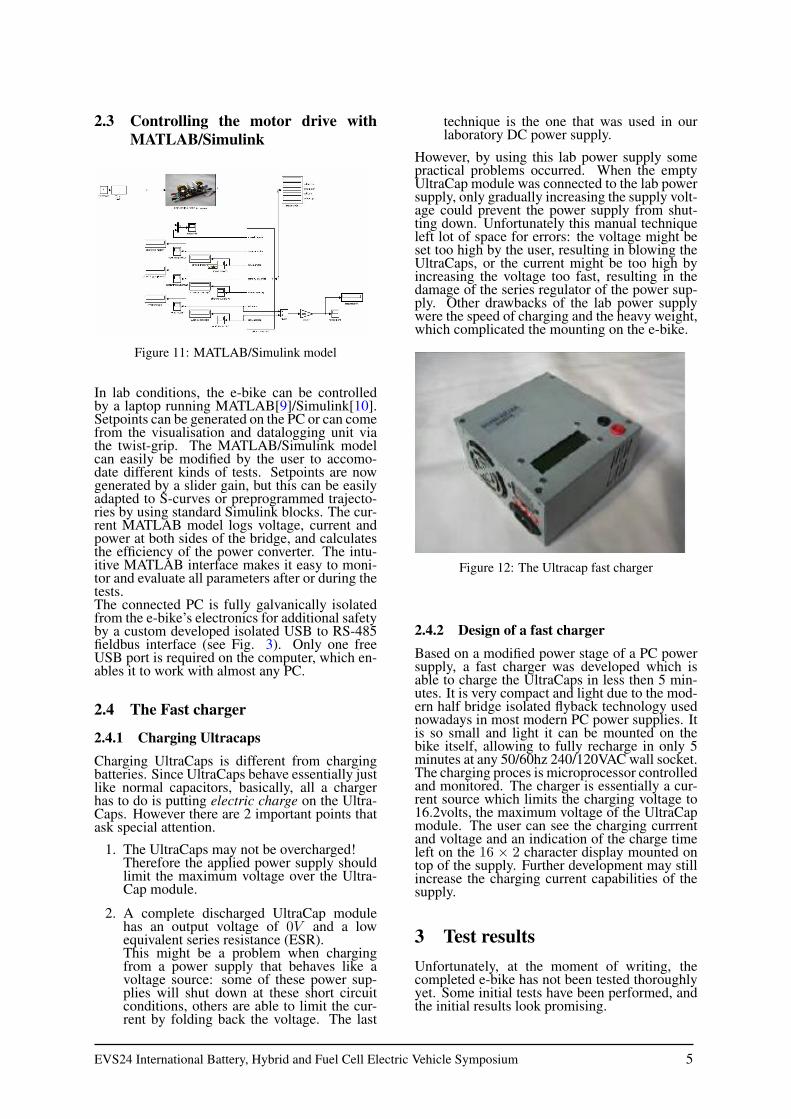
2.3 Controlling the motor drive withMATLAB/Simulink
Figure 11: MATLAB/Simulink model
In lab conditions, the e-bike can be controlledby a laptop running MATLAB[9]/Simulink[10].Setpoints can be generated on the PC or can comefrom the visualisation and datalogging unit viathe twist-grip. The MATLAB/Simulink modelcan easily be modified by the user to accomo-date different kinds of tests. Setpoints are nowgenerated by a slider gain, but this can be easilyadapted to S-curves or preprogrammed trajecto-ries by using standard Simulink blocks. The cur-rent MATLAB model logs voltage, current andpower at both sides of the bridge, and calculatesthe efficiency of the power converter. The intu-itive MATLAB interface makes it easy to moni-tor and evaluate all parameters after or during thetests.The connected PC is fully galvanically isolatedfrom the e-bike’s electronics for additional safetyby a custom developed isolated USB to RS-485fieldbus interface (see Fig. 3). Only one freeUSB port is required on the computer, which en-ables it to work with almost any PC.
2.4 The Fast charger
2.4.1 Charging UltracapsCharging UltraCaps is different from chargingbatteries. Since UltraCaps behave essentially justlike normal capacitors, basically, all a chargerhas to do is putting electric charge on the Ultra-Caps. However there are 2 important points thatask special attention.
1. The UltraCaps may not be overcharged!Therefore the applied power supply shouldlimit the maximum voltage over the Ultra-Cap module.
2. A complete discharged UltraCap modulehas an output voltage of 0V and a lowequivalent series resistance (ESR).This might be a problem when chargingfrom a power supply that behaves like avoltage source: some of these power sup-plies will shut down at these short circuitconditions, others are able to limit the cur-rent by folding back the voltage. The last
technique is the one that was used in ourlaboratory DC power supply.
However, by using this lab power supply somepractical problems occurred. When the emptyUltraCap module was connected to the lab powersupply, only gradually increasing the supply volt-age could prevent the power supply from shut-ting down. Unfortunately this manual techniqueleft lot of space for errors: the voltage might beset too high by the user, resulting in blowing theUltraCaps, or the current might be too high byincreasing the voltage too fast, resulting in thedamage of the series regulator of the power sup-ply. Other drawbacks of the lab power supplywere the speed of charging and the heavy weight,which complicated the mounting on the e-bike.
Figure 12: The Ultracap fast charger
2.4.2 Design of a fast chargerBased on a modified power stage of a PC powersupply, a fast charger was developed which isable to charge the UltraCaps in less then 5 min-utes. It is very compact and light due to the mod-ern half bridge isolated flyback technology usednowadays in most modern PC power supplies. Itis so small and light it can be mounted on thebike itself, allowing to fully recharge in only 5minutes at any 50/60hz 240/120VAC wall socket.The charging proces is microprocessor controlledand monitored. The charger is essentially a cur-rent source which limits the charging voltage to16.2volts, the maximum voltage of the UltraCapmodule. The user can see the charging currrentand voltage and an indication of the charge timeleft on the 16 × 2 character display mounted ontop of the supply. Further development may stillincrease the charging current capabilities of thesupply.
3 Test resultsUnfortunately, at the moment of writing, thecompleted e-bike has not been tested thoroughlyyet. Some initial tests have been performed, andthe initial results look promising.
EVS24 International Battery, Hybrid and Fuel Cell Electric Vehicle Symposium 5

• With one full UltraCap charge, the initialtest showed the e-bike has a range of 1.4kmon UltraCap power only. The average speedduring this test was 14.6km/h, maximumspeed was 27.1km/h, without pedalling!
• At 27.1km/h the motor produces a backemf of 30V , and delivers a maximum powerof 307W . This is well above the maximumcontinuous rated power of the hub motor.
• The maximum speed without help from thecyclist decreases as the UltraCap voltagedecreases, because the current levels in theboost converter are limited.
• The range of the e-bike may seem verysmall, but will be drastically increase whenspeed is lowered, or when the electric bicy-cle is used as a pedelec.
• The regenerative braking system alsoproved to work well from speeds above5km/h. At lower speeds the back emf volt-age is too low to brake effectively. Furthertesting will have to be done to explore thelimits of the braking system.
4 Conclusions
Figure 13: The UltraCap e-bike prototype
A stable platform to test the use of UltraCaps inelectric bicycles has been succesfully developed.When using Ultracaps a special power convertertopology is neccesary to get as much energy aspossible from the UltraCaps. The Split-Pi topol-ogy is very well suited to get the maximum po-tential out of the Ultracaps. A split-PI motordrive controlled by a DSP, SEPIC converters tosupply the electronics, a fast charger for the Ul-traCaps, a data logging and visualisation unit,...were all developed from scratch, only using lowcost power electronics.Ultracaps do not pack as much energy as batterytechnologies, but have vast advantages when itcomes to fast charging and long life. For an e-bike a long range is not so important when you
can recharge in less then 5 minutes.In spite of the promising first tests, thorough test-ing of the e-bike still has to be done. In the nearfuture the evaluation of the UltraCap e-bike con-cept for daily use and the evaluation of the effi-ciency of regenerative braking will be started.
EVS24 International Battery, Hybrid and Fuel Cell Electric Vehicle Symposium 6

References[1] J.Cappelle et.al., The pedelec market in Flan-
ders: The position of the bicycle dealers, The22th International Battery, Hybrid and Fuel CellElectric Vehicle Symposium, Yokohama, Japan,oct. 2006.
[2] A. Burke, Ultracapacitors: why, how, andwhere is the technology, Journal of PowerSources, Vol.91, pp 37-50, 2000.
[3] J.Cappelle et.al., Electrically Assisted Cy-cling around the World, The 20th InternationalBattery, Hybrid and Fuel Cell Electric Vehi-cle Symposium, Long Beach, California, nov.2003.
[4] J. Cappelle et.al., Personalized testing methodfor E-PACs, The 21th International Battery, Hy-brid and Fuel Cell Electric Vehicle Symposium,Monaco, april 2005.
[5] R.E.Smith, The RS485 Communica-tions Authority, Quick reference forRS485, RS422, RS232 and RS423,http://www.rs485.com/rs485spec.html, ac-cessed on 2008-11-1.
[6] Lazar Rozenblat, SMPS switching power sup-ply design, Lazar’s Power Electronics Guide,http://www.smps.us/, accessed on 2009-02-10.
[7] Maxim/Dallas Semiconductor, SEPIC Equa-tions and Component Ratings, Applicationnote 1051 Apr 23 2002, http://www.maxim-ic.com/appnotes.cfm/an pk/1051/, accessed on2008-11-10.
[8] Tim Crocker, Seamless motoring withsplit-PI, Electronics Weekly Magazine, Nov.2008, http://www.greenenergytechnologies.eu,accessed on 2009-04-02.
[9] The Mathworks, MATLAB - TheLanguage Of Technical Computing,http://www.mathworks.com/products/matlab/,accessed on 2009-03-12.
[10] The Mathworks, Simulink - Sim-ulation and Model-Based Design,http://www.mathworks.com/products/simulink/,accessed on 2009-03-12.
AuthorsJan Cappelle graduated in 1999as electro-mechanical engineer atthe Katholieke Universiteit Leu-ven. In 2008 he obtained aPhD in engineering sciences at theVrije Universiteit Brussel. HisPhD thesis was an objective andsubjective study of the perfor-mance of electric bicycles. At theKaHo Sint-Lieven engineering de-partment in Ghent, he is a full-time lecturer in electric power sys-tems. His research is mainly inthe domain of intelligent energymanagement, autonomous photo-voltaics and spectral responses ofsolar cells.
Niels Polfliet is graduating thisyear as an control and automa-tion engineer at the engineeringdepartment of KaHo Sint-Lievenin Ghent. This paper is mainlybased on work that was done inthe framework of his master thesis.His main interests are embeddedsoftware developement, PermanentMagnet Brushless DC motor devel-opement and power electronics ingeneral.
Jean-Marc Timmermans graduatedin 2003 as an ElectromechanicalEngineer at the Vrije UniversiteitBrussel. His master thesis dealtwith the development of a testbench for electric bicycles. Asan academic assistant, he was in-volved in projects about the evalu-ation of the environmental impactof both conventional and alterna-tive vehicles and was also involvedin the development and evaluationof electric bikes for postal deliveryuse. Further research goes to theevaluation and optimization of hy-brid electric drive trains for vehi-cles.
EVS24 International Battery, Hybrid and Fuel Cell Electric Vehicle Symposium 7