Embed Size (px)
Citation preview
E-Band Wireless Backhaul: System Design & Test Challenges
Presented by:
Agilent Technologies, Inc.
Daren McClearnon
Sang-kyo Shin
Webcast, 27 March 2014
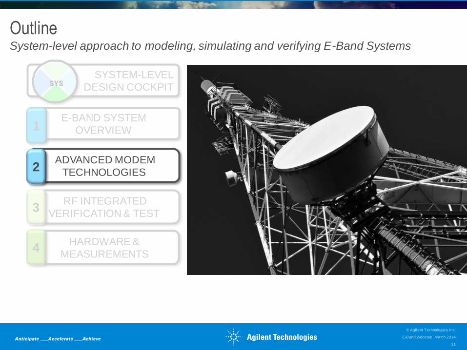
Outline System-level approach to modeling, simulating and verifying E-Band Systems
E-Band Webcast , March 2014
© Agilent Technologies, Inc.
2
HARDWARE &
MEASUREMENTS 4
ADVANCED MODEM
TECHNOLOGIES 2
E-BAND SYSTEM
OVERVIEW 1
RF INTEGRATED
VERIFICATION & TEST 3
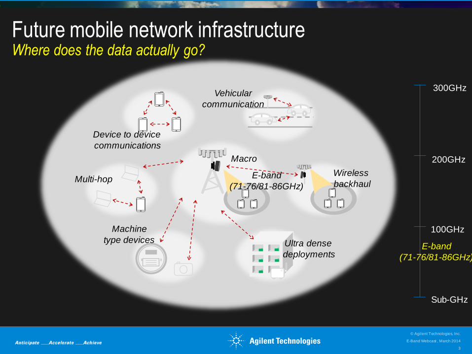
Future mobile network infrastructure Where does the data actually go?
Device to device
communications
Vehicular
communication
Wireless
backhaul
Ultra dense
deployments
Machine
type devices
Multi-hop
Macro
Sub-GHz
100GHz
200GHz
300GHz
E-band
(71-76/81-86GHz)
E-band
(71-76/81-86GHz)
E-Band Webcast , March 2014
© Agilent Technologies, Inc.
3
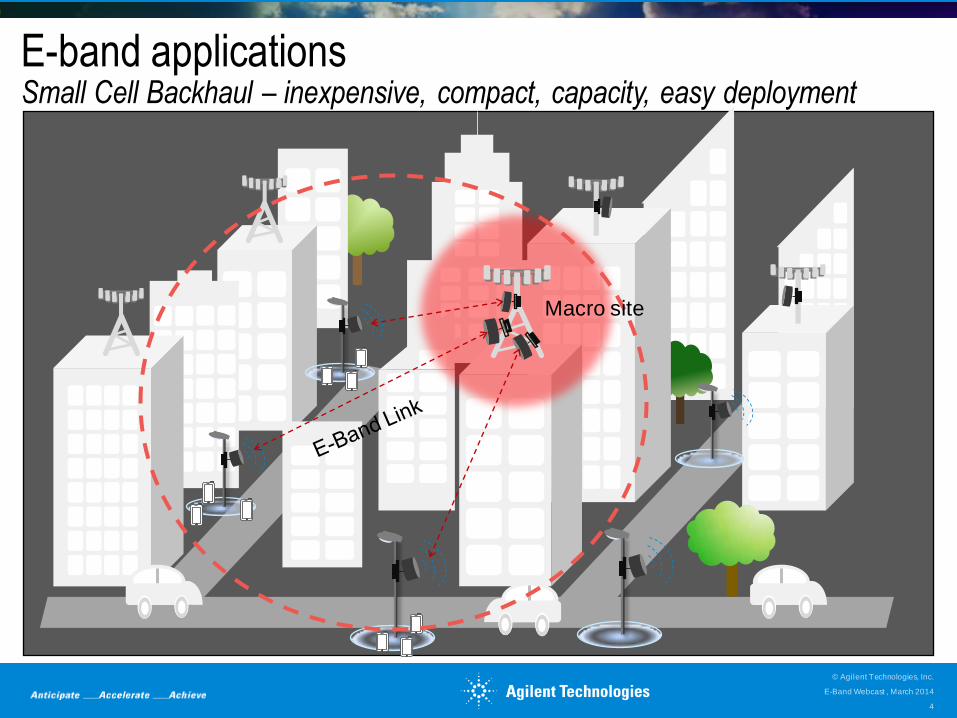
E-band applications Small Cell Backhaul – inexpensive, compact, capacity, easy deployment
Macro site
E-Band Webcast , March 2014
© Agilent Technologies, Inc.
4
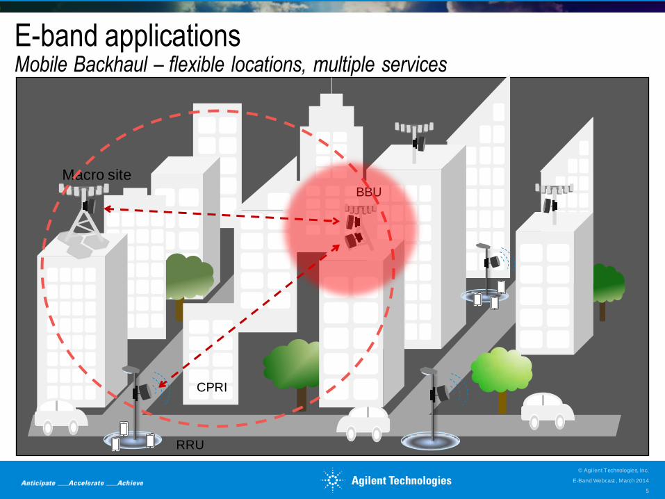
E-band applications Mobile Backhaul – flexible locations, multiple services
BBU
RRU
Macro site
CPRI
E-Band Webcast , March 2014
© Agilent Technologies, Inc.
5
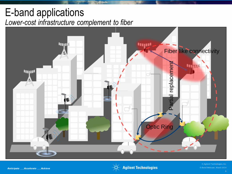
E-band applications Lower-cost infrastructure complement to fiber
o
p
t
i
c
o
p
t
i
c
o
p
t
i
c Optic Ring
Part
ial re
pla
cem
en
t
Fiber like connectivity
E-Band Webcast , March 2014
© Agilent Technologies, Inc.
6
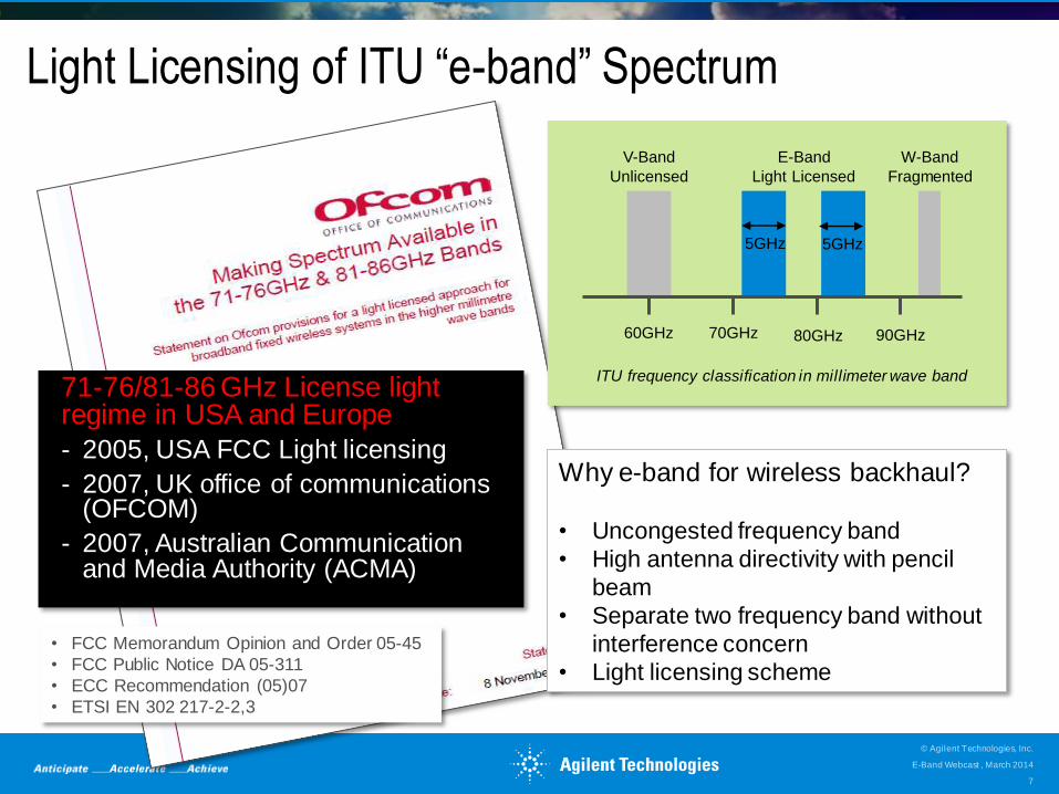
Light Licensing of ITU “e-band” Spectrum
71-76/81-86 GHz License light regime in USA and Europe
- 2005, USA FCC Light licensing
- 2007, UK office of communications (OFCOM)
- 2007, Australian Communication and Media Authority (ACMA)
• FCC Memorandum Opinion and Order 05-45
• FCC Public Notice DA 05-311
• ECC Recommendation (05)07
• ETSI EN 302 217-2-2,3
Why e-band for wireless backhaul?
• Uncongested frequency band
• High antenna directivity with pencil
beam
• Separate two frequency band without
interference concern
• Light licensing scheme
60GHz 70GHz 80GHz 90GHz
V-Band
Unlicensed
E-Band
Light Licensed
W-Band
Fragmented
5GHz 5GHz
ITU frequency classification in millimeter wave band
E-Band Webcast , March 2014
© Agilent Technologies, Inc.
7
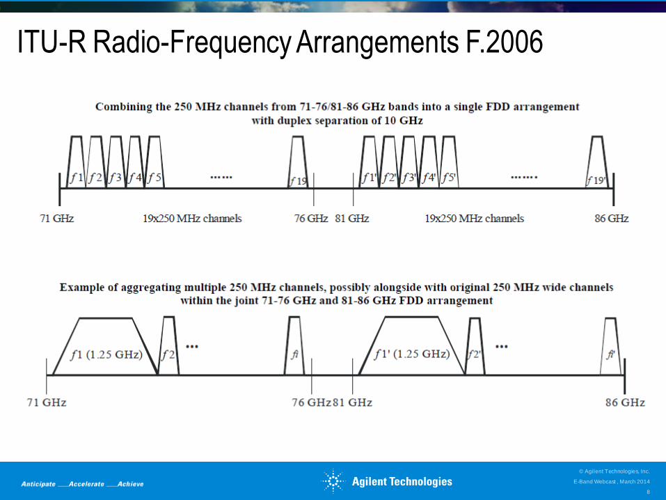
ITU-R Radio-Frequency Arrangements F.2006
E-Band Webcast , March 2014
© Agilent Technologies, Inc.
8
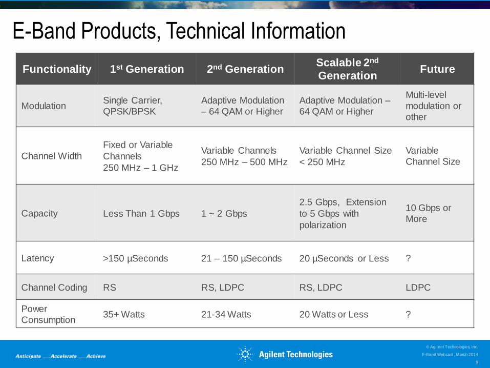
E-Band Products, Technical Information
Functionality 1st Generation 2nd Generation Scalable 2nd
Generation Future
Modulation Single Carrier, QPSK/BPSK
Adaptive Modulation – 64 QAM or Higher
Adaptive Modulation – 64 QAM or Higher
Multi-level
modulation or
other
Channel Width
Fixed or Variable
Channels
250 MHz – 1 GHz
Variable Channels
250 MHz – 500 MHz
Variable Channel Size
< 250 MHz
Variable
Channel Size
Capacity Less Than 1 Gbps 1 ~ 2 Gbps
2.5 Gbps, Extension
to 5 Gbps with
polarization
10 Gbps or More
Latency >150 µSeconds 21 – 150 µSeconds 20 µSeconds or Less ?
Channel Coding RS RS, LDPC RS, LDPC LDPC
Power Consumption
35+ Watts 21-34 Watts 20 Watts or Less ?
E-Band Webcast , March 2014
© Agilent Technologies, Inc.
9
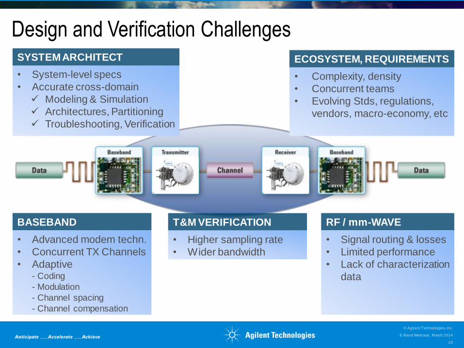
Design and Verification Challenges
• Signal routing & losses
• Limited performance
• Lack of characterization
data
RF / mm-WAVE
• System-level specs
• Accurate cross-domain
Modeling & Simulation
Architectures, Partitioning
Troubleshooting, Verification
SYSTEM ARCHITECT
• Advanced modem techn.
• Concurrent TX Channels
• Adaptive - Coding
- Modulation
- Channel spacing
- Channel compensation
BASEBAND
• Higher sampling rate
• Wider bandwidth
T&M VERIFICATION
• Complexity, density
• Concurrent teams
• Evolving Stds, regulations,
vendors, macro-economy, etc
ECOSYSTEM, REQUIREMENTS
E-Band Webcast , March 2014
© Agilent Technologies, Inc.
10
SYSTEM-LEVEL
DESIGN COCKPIT
HARDWARE &
MEASUREMENTS 4
E-BAND SYSTEM
OVERVIEW 1
RF INTEGRATED
VERIFICATION & TEST 3
ADVANCED MODEM
TECHNOLOGIES 2
Outline System-level approach to modeling, simulating and verifying E-Band Systems
E-Band Webcast , March 2014
© Agilent Technologies, Inc.
11
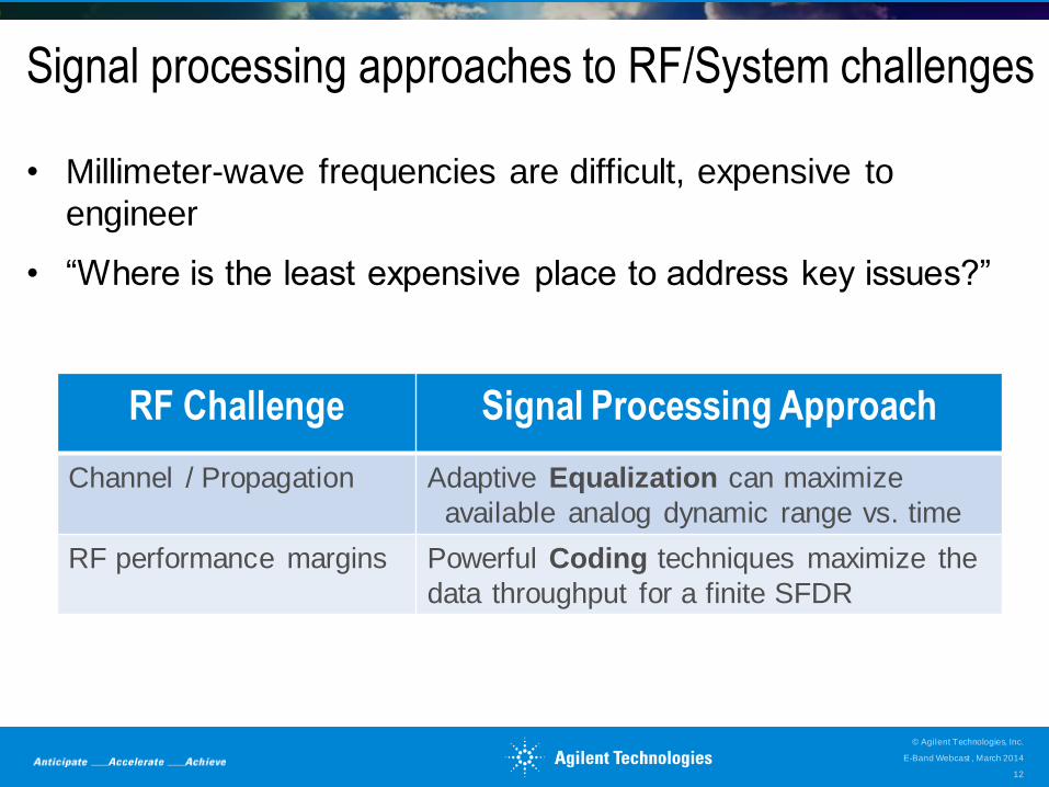
Signal processing approaches to RF/System challenges
• Millimeter-wave frequencies are difficult, expensive to
engineer
• “Where is the least expensive place to address key issues?”
RF Challenge Signal Processing Approach
Channel / Propagation Adaptive Equalization can maximize
available analog dynamic range vs. time
RF performance margins Powerful Coding techniques maximize the
data throughput for a finite SFDR
E-Band Webcast , March 2014
© Agilent Technologies, Inc.
12
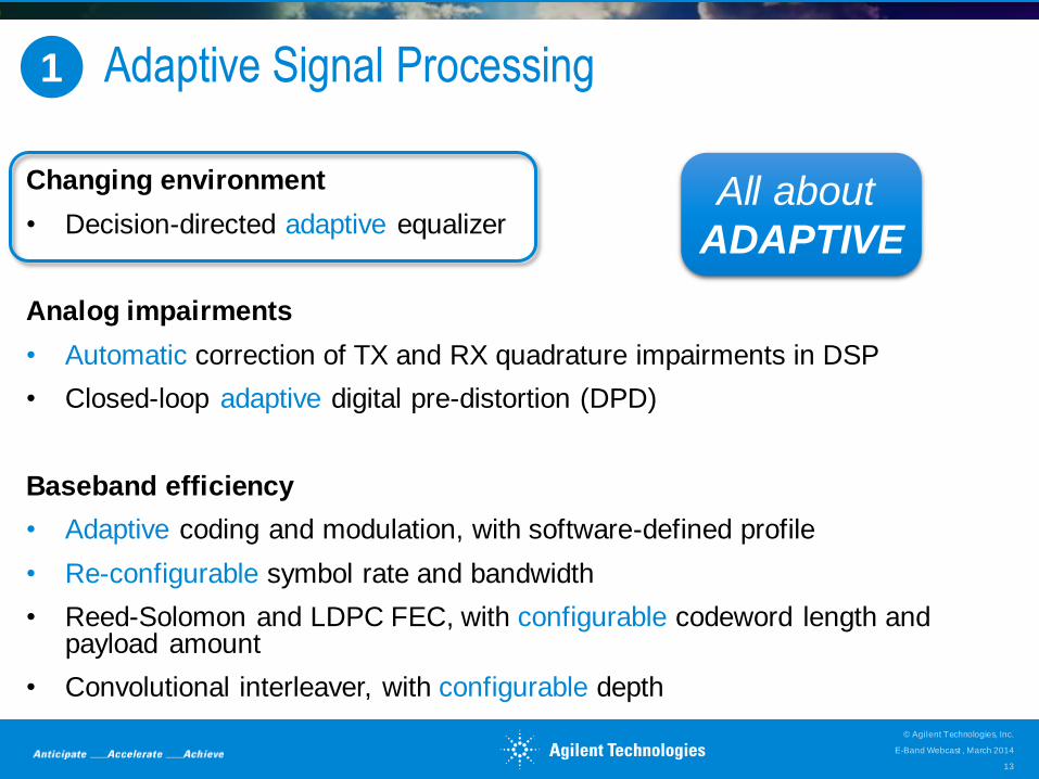
#1 - Adaptive Signal Processing
Changing environment
• Decision-directed adaptive equalizer
Analog impairments
• Automatic correction of TX and RX quadrature impairments in DSP
• Closed-loop adaptive digital pre-distortion (DPD)
Baseband efficiency
• Adaptive coding and modulation, with software-defined profile
• Re-configurable symbol rate and bandwidth
• Reed-Solomon and LDPC FEC, with configurable codeword length and payload amount
• Convolutional interleaver, with configurable depth
All about
ADAPTIVE
1
E-Band Webcast , March 2014
© Agilent Technologies, Inc.
13
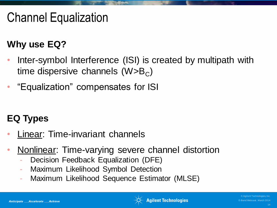
Channel Equalization
Why use EQ?
• Inter-symbol Interference (ISI) is created by multipath with
time dispersive channels (W>BC)
• “Equalization” compensates for ISI
EQ Types
• Linear: Time-invariant channels
• Nonlinear: Time-varying severe channel distortion - Decision Feedback Equalization (DFE)
- Maximum Likelihood Symbol Detection
- Maximum Likelihood Sequence Estimator (MLSE)
E-Band Webcast , March 2014
© Agilent Technologies, Inc.
14
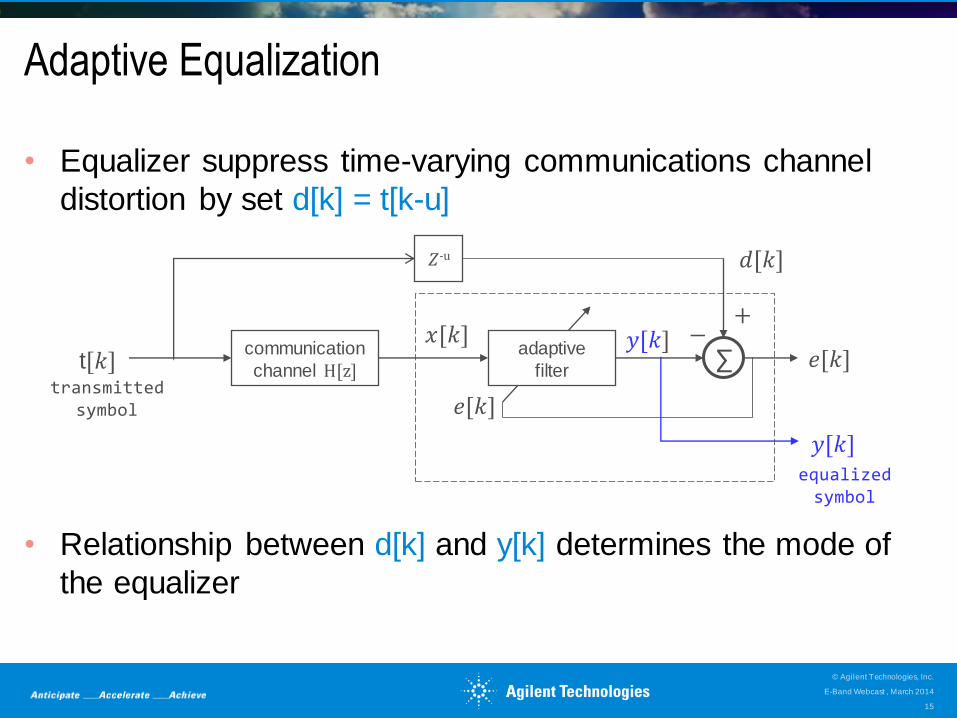
• Equalizer suppress time-varying communications channel
distortion by set d[k] = t[k-u]
• Relationship between d[k] and y[k] determines the mode of
the equalizer
𝑒[𝑘]
𝑒[𝑘] 𝑦[𝑘]
𝑦[𝑘] equalized symbol
Adaptive Equalization
∑ adaptive
filter
𝑑[𝑘]
𝑥[𝑘] t[𝑘]
+ −
transmitted symbol
communication
channel H[z]
𝑍-u
E-Band Webcast , March 2014
© Agilent Technologies, Inc.
15
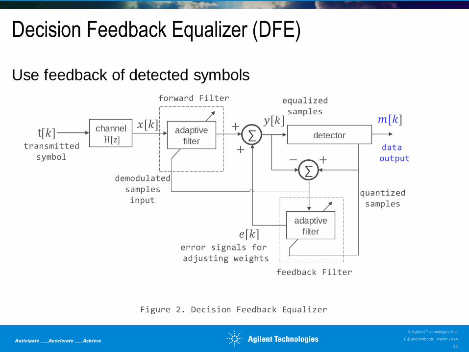
Decision Feedback Equalizer (DFE)
Use feedback of detected symbols
∑
𝑚[𝑘]
𝑒[𝑘]
𝑥[𝑘] 𝑦[𝑘] t[𝑘]
+ −
transmitted symbol
Figure 2. Decision Feedback Equalizer
adaptive
filter
∑ +
+
adaptive
filter detector
channel
H[z]
demodulated samples input
forward Filter
feedback Filter
data output
quantized samples
error signals for adjusting weights
equalized samples
E-Band Webcast , March 2014
© Agilent Technologies, Inc.
16
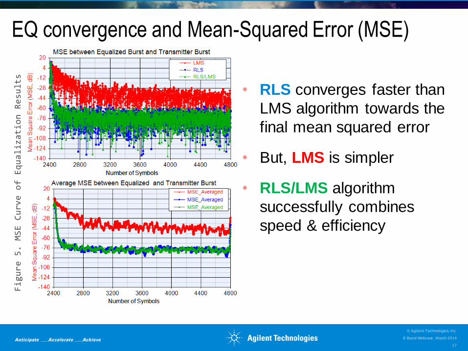
EQ convergence and Mean-Squared Error (MSE)
• RLS converges faster than
LMS algorithm towards the
final mean squared error
• But, LMS is simpler
• RLS/LMS algorithm
successfully combines
speed & efficiency
Figure 5. MSE Curve of Equalization Results
E-Band Webcast , March 2014
© Agilent Technologies, Inc.
17
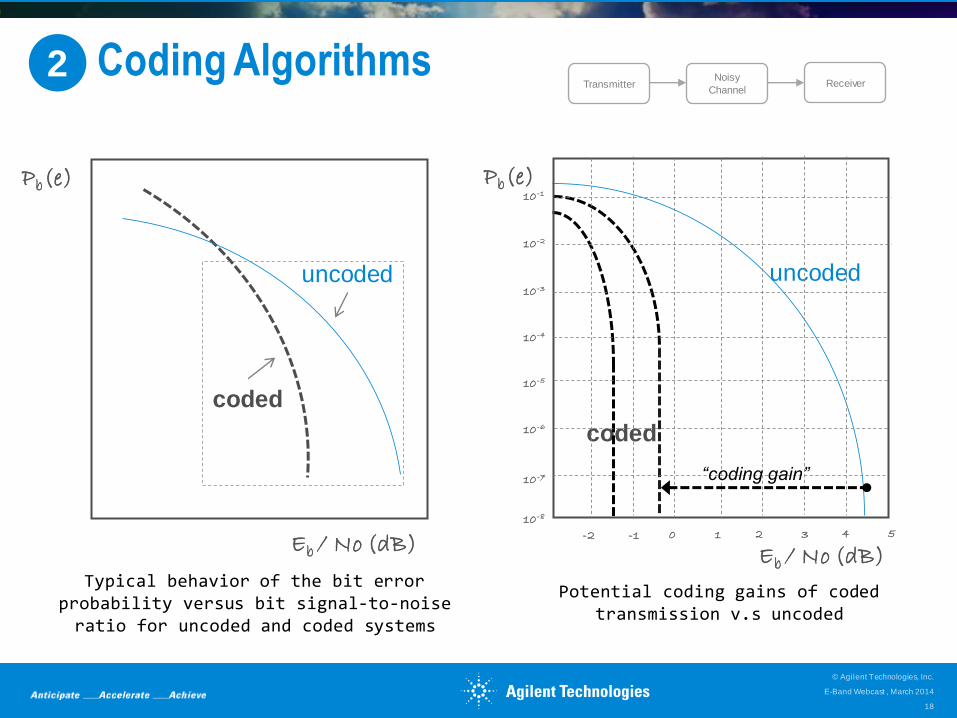
#2 Coding Algorithms
Typical behavior of the bit error probability versus bit signal-to-noise ratio for uncoded and coded systems
2 Transmitter
Noisy
Channel Receiver
uncoded
coded
coded
uncoded
Pb(e)
Eb / No (dB)
Potential coding gains of coded transmission v.s uncoded
Pb(e)
Eb / No (dB)
10 -1
10 -2
10 -3
10 -4
10 -5
10 -6
10 -7
10 -8
-2 -1 0 1 2 3 4 5
“coding gain”
E-Band Webcast , March 2014
© Agilent Technologies, Inc.
18
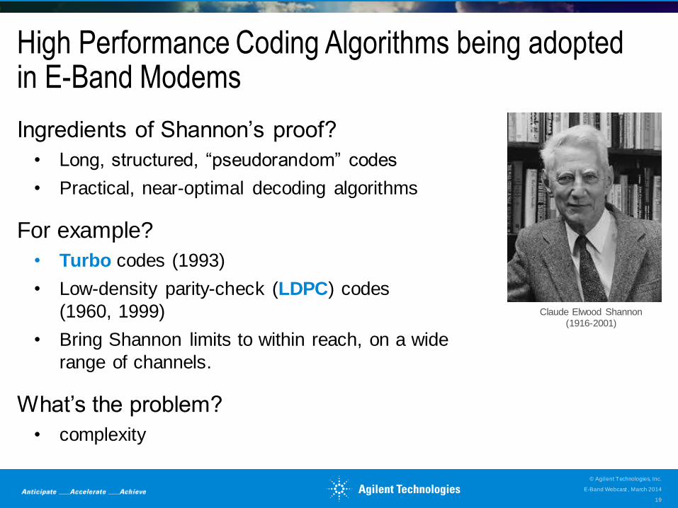
High Performance Coding Algorithms being adopted in E-Band Modems
Ingredients of Shannon’s proof?
• Long, structured, “pseudorandom” codes
• Practical, near-optimal decoding algorithms
For example?
• Turbo codes (1993)
• Low-density parity-check (LDPC) codes
(1960, 1999)
• Bring Shannon limits to within reach, on a wide
range of channels.
What’s the problem?
• complexity
Claude Elwood Shannon
(1916-2001)
E-Band Webcast , March 2014
© Agilent Technologies, Inc.
19
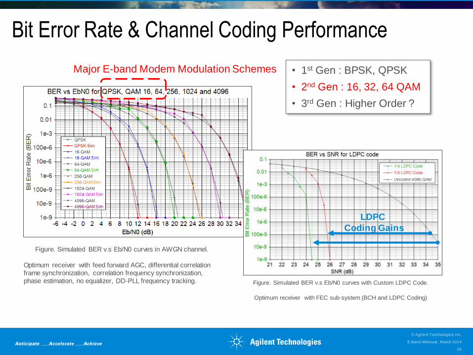
Bit Error Rate & Channel Coding Performance
Figure. Simulated BER v.s Eb/N0 curves in AWGN channel.
Optimum receiver with feed forward AGC, differential correlation
frame synchronization, correlation frequency synchronization,
phase estimation, no equalizer, DD-PLL frequency tracking.
LDPC
Coding Gains
Figure. Simulated BER v.s Eb/N0 curves with Custom LDPC Code.
Optimum receiver with FEC sub-system (BCH and LDPC Coding)
• 1st Gen : BPSK, QPSK
• 2nd Gen : 16, 32, 64 QAM
• 3rd Gen : Higher Order ?
Major E-band Modem Modulation Schemes
E-Band Webcast , March 2014
© Agilent Technologies, Inc.
20
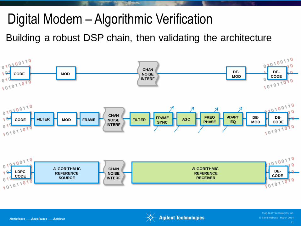
Digital Modem – Algorithmic Verification
Building a robust DSP chain, then validating the architecture
CODE MOD DE-
CODE
CHAN
NOISE
INTERF
DE-
MOD
FRAME CODE MOD DE-
CODE FRAME
SYNC
ADAPT
EQ AGC FILTER
CHAN
NOISE
INTERF
FREQ
PHASE DE-
MOD FILTER
LDPC
CODE
DE-
CODE
ALGORITHMIC
REFERENCE
RECEIVER
CHAN
NOISE
INTERF
ALGORITHM IC
REFERENCE
SOURCE
E-Band Webcast , March 2014
© Agilent Technologies, Inc.
21
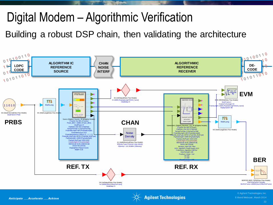
Digital Modem – Algorithmic Verification
Building a robust DSP chain, then validating the architecture
CODE MOD DE-
CODE
CHAN
NOISE
INTERF
DE-
MOD FRAME CODE MOD
DE-
CODE FRAME
SYNC
ADAPT
EQ AGC FILTER
CHAN
NOISE
INTERF
FREQ
PHASE DE-
MOD FILTER LDPC
CODE
DE-
CODE
ALGORITHMIC
REFERENCE
RECEIVER
CHAN
NOISE
INTERF
ALGORITHM IC
REFERENCE
SOURCE
InitialDelay=0N=100000 [NumOfBitsPerFrame]D4 {InitDelay@Data Flow Models}
InitialDelay=0N=10000 [PayloadLength*DSSS_factor]
D1 {InitDelay@Data Flow Models}
(X-Y)2
N
DisplayOption=dBFrameLength=10000 [PayloadLength*DSSS_factor]
FramesToAverage=10StartFrame=1
EVM {RMSE@Data Flow Models}
Noise
Density
NDensity=-131.021dBm [NDensity]
NDensityType=Constant noise densityA1 {AddNDensity@Data Flow Models}
1 1 0 1 0
DataPattern=PN15B2 {DataPattern@Data Flow Models}
MathLang
M1 {MathLang@Data Flow Models}
TEST
REF
BitsPerFrame=100000 [NumOfBitsPerFrame]StartStopOption=Samples
BERFER {BER_FER@Data Flow Models}
MathLang
M2 {MathLang@Data Flow Models}
BPSK, Q PSK, . . . , up t o 4096- Q AM8- PSK, 16- PSK, 16- APSK, 32- APSK
16- St ar Q AM , 32- St ar - Q AM ,
and Cust om APSK
Dat a PayloadPr eam bleI dle
Fr am e St r uct ur e
Spr eading Code
G ener at or
X
Digital Modem Sourcefor Linear Modulation
DSSS Syst em
Rolloff=0.35ShapingFilter=Raised Cosine
DSSS=NO [DSSS]IdleInterval=2e-6s [IdleInterval]GuardLength=0 [GuardLength]Payload_ModType=1024-QAM
PayloadLength=10000 [PayloadLength]Preamble_ModType=BPSK [Preamble_ModType]
PreambleSequence=(400x1) [1; -1; 1; 1]PreambleSource=YES
PreambleLength=400 [PreambleLength]SampsPerChip=4 [SampsPerChip]
ChipRate=10e+6Hz [ChipRate]InitialPhase=0°
Power_dBm=-10dBm [Power_dBm]FCarrier=5e+9Hz [FCarrier]
Source {DigMod_SourceL_RF@DigMod Models}
Decision
Device
Adapt ive
Equalizer
+
Equalizer(LE and DFE)
LMS and RLS
Adaptive Algorithm
Digital Modem Receiver
PLL_Bandwidth=4HzFreqTrackMode=DD-PLL
Fraction=1EQ_Type= NO Equalizer
Np=197
PhaseEstimator=YESLf=200Nf=200
FreqSync_Mode= Corr
SearchLength=100FrameSync_Algorithm=DiffCorr
AGC_Algorithm=FeedForward_AGCReceiver_Filter=NO Filter
DSSS=NO [DSSS]IdleInterval=2e-6s [IdleInterval]GuardLength=0 [GuardLength]Payload_ModType=1024-QAM
PayloadLength=10000 [PayloadLength]Preamble_ModType=BPSK [Preamble_ModType]
PreambleLength=400 [PreambleLength]SampsPerChip=4 [SampsPerChip]
ChipRate=10e+6Hz [ChipRate]FCarrier=5e+9Hz [FCarrier]
Subnetwork1 {DigMod_ReceiverL_EQ_RF@DigMod Models}PRBS
BER
EVM
CHAN
REF. TX REF. RX
E-Band Webcast , March 2014
© Agilent Technologies, Inc.
22
InitialDelay=0N=100000 [NumOfBitsPerFrame]D4 {InitDelay@Data Flow Models}
InitialDelay=0N=10000 [PayloadLength*DSSS_factor]
D1 {InitDelay@Data Flow Models}
(X-Y)2
N
DisplayOption=dBFrameLength=10000 [PayloadLength*DSSS_factor]
FramesToAverage=10StartFrame=1
EVM {RMSE@Data Flow Models}
Noise
Density
NDensity=-131.021dBm [NDensity]
NDensityType=Constant noise densityA1 {AddNDensity@Data Flow Models}
1 1 0 1 0
DataPattern=PN15B2 {DataPattern@Data Flow Models}
MathLang
M1 {MathLang@Data Flow Models}
TEST
REF
BitsPerFrame=100000 [NumOfBitsPerFrame]StartStopOption=Samples
BERFER {BER_FER@Data Flow Models}
MathLang
M2 {MathLang@Data Flow Models}
BPSK, Q PSK, . . . , up t o 4096- Q AM8- PSK, 16- PSK, 16- APSK, 32- APSK
16- St ar Q AM , 32- St ar - Q AM ,
and Cust om APSK
Dat a PayloadPr eam bleI dle
Fr am e St r uct ur e
Spr eading Code
G ener at or
X
Digital Modem Sourcefor Linear Modulation
DSSS Syst em
Rolloff=0.35ShapingFilter=Raised Cosine
DSSS=NO [DSSS]IdleInterval=2e-6s [IdleInterval]GuardLength=0 [GuardLength]Payload_ModType=1024-QAM
PayloadLength=10000 [PayloadLength]Preamble_ModType=BPSK [Preamble_ModType]
PreambleSequence=(400x1) [1; -1; 1; 1]PreambleSource=YES
PreambleLength=400 [PreambleLength]SampsPerChip=4 [SampsPerChip]
ChipRate=10e+6Hz [ChipRate]InitialPhase=0°
Power_dBm=-10dBm [Power_dBm]FCarrier=5e+9Hz [FCarrier]
Source {DigMod_SourceL_RF@DigMod Models}
Decision
Device
Adapt ive
Equalizer
+
Equalizer(LE and DFE)
LMS and RLS
Adaptive Algorithm
Digital Modem Receiver
PLL_Bandwidth=4HzFreqTrackMode=DD-PLL
Fraction=1EQ_Type= NO Equalizer
Np=197
PhaseEstimator=YESLf=200Nf=200
FreqSync_Mode= Corr
SearchLength=100FrameSync_Algorithm=DiffCorr
AGC_Algorithm=FeedForward_AGCReceiver_Filter=NO Filter
DSSS=NO [DSSS]IdleInterval=2e-6s [IdleInterval]GuardLength=0 [GuardLength]Payload_ModType=1024-QAM
PayloadLength=10000 [PayloadLength]Preamble_ModType=BPSK [Preamble_ModType]
PreambleLength=400 [PreambleLength]SampsPerChip=4 [SampsPerChip]
ChipRate=10e+6Hz [ChipRate]FCarrier=5e+9Hz [FCarrier]
Subnetwork1 {DigMod_ReceiverL_EQ_RF@DigMod Models}
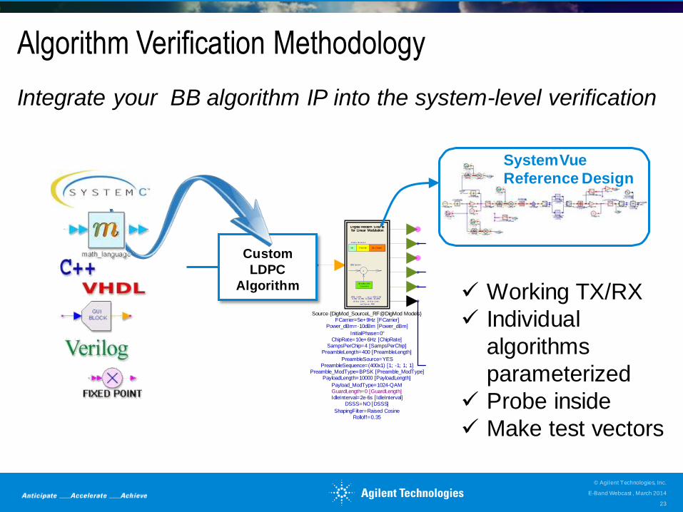
Algorithm Verification Methodology
Integrate your BB algorithm IP into the system-level verification
SystemVue
Reference Design
Custom
LDPC
Algorithm Working TX/RX
Individual
algorithms
parameterized
Probe inside
Make test vectors
E-Band Webcast , March 2014
© Agilent Technologies, Inc.
23
ADVANCED MODEM
TECHNOLOGIES 2
SYSTEM-LEVEL
DESIGN COCKPIT
HARDWARE &
MEASUREMENTS 4
E-BAND SYSTEM
OVERVIEW 1
RF INTEGRATED
VERIFICATION & TEST 3
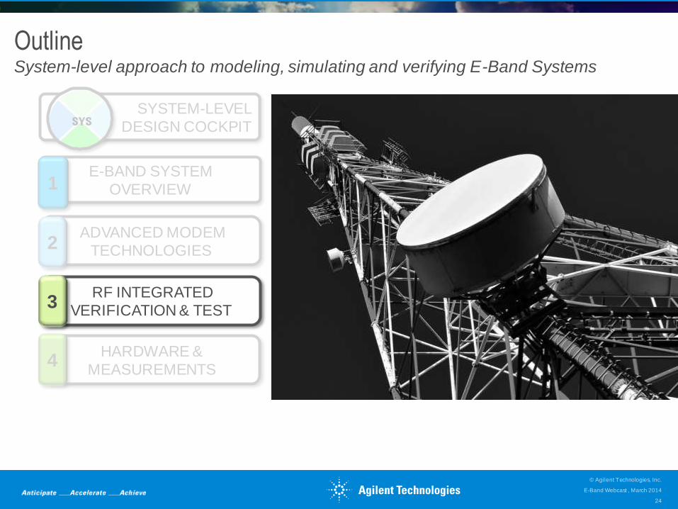
Outline System-level approach to modeling, simulating and verifying E-Band Systems
E-Band Webcast , March 2014
© Agilent Technologies, Inc.
24
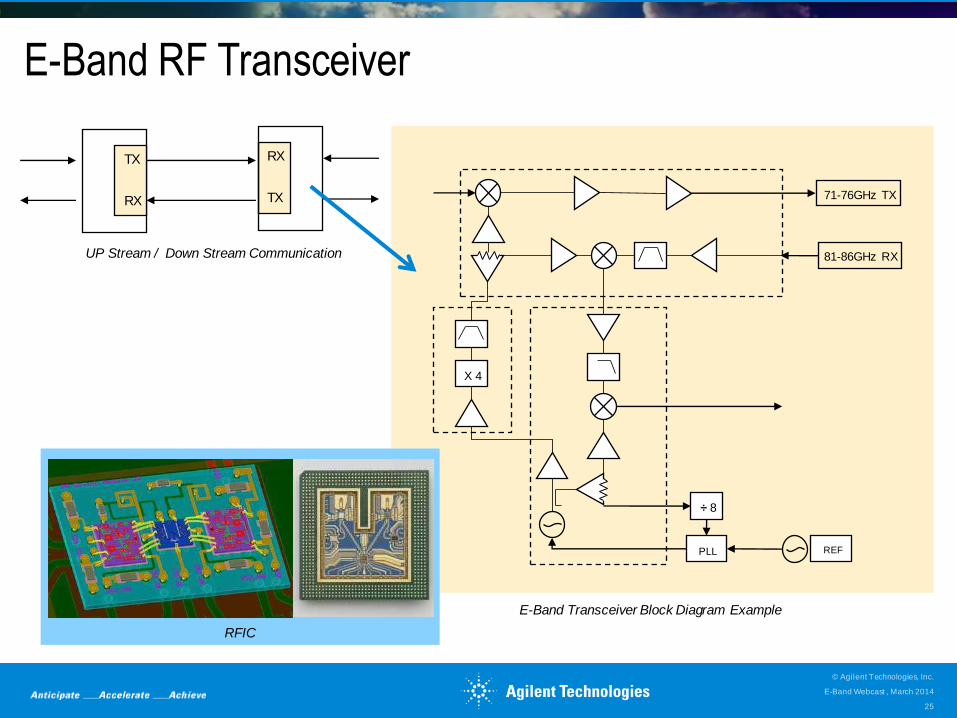
E-Band RF Transceiver
E-Band Webcast , March 2014
© Agilent Technologies, Inc.
25
TX
RX
RX
TX
UP Stream / Down Stream Communication
X 4
REF PLL
÷ 8
71-76GHz TX
81-86GHz RX
E-Band Transceiver Block Diagram Example
RFIC
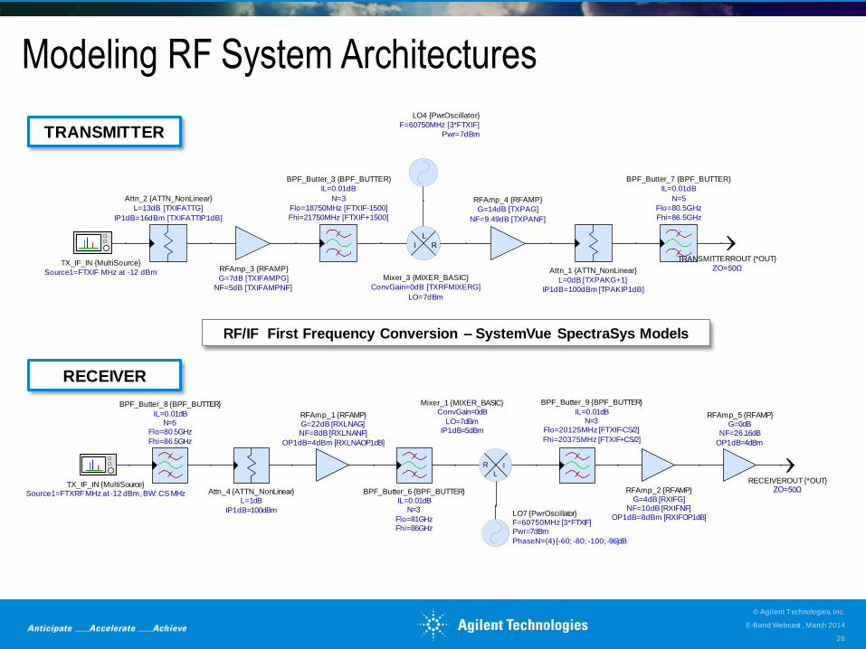
Modeling RF System Architectures
Source1=FTXIF MHz at -12 dBm
TX_IF_IN {MultiSource}
Fhi=21750MHz [FTXIF+1500]
Flo=18750MHz [FTXIF-1500]
N=3
IL=0.01dB
BPF_Butter_3 {BPF_BUTTER}
RI
L
LO=7dBm
ConvGain=0dB [TXRFMIXERG]
Mixer_3 {MIXER_BASIC}
NF=9.49dB [TXPANF]
G=14dB [TXPAG]
RFAmp_4 {RFAMP}
IP1dB=100dBm [TPAKIP1dB]
L=0dB [TXPAKG+1]
Attn_1 {ATTN_NonLinear}
Fhi=86.5GHz
Flo=80.5GHz
N=5
IL=0.01dB
BPF_Butter_7 {BPF_BUTTER}
ZO=50Ω
TRANSMITTERROUT {*OUT}
NF=5dB [TXIFAMPNF]
G=7dB [TXIFAMPG]
RFAmp_3 {RFAMP}
IP1dB=16dBm [TXIFATTIP1dB]
L=13dB [TXIFATTG]
Attn_2 {ATTN_NonLinear}
Pwr=7dBm
F=60750MHz [3*FTXIF]
LO4 {PwrOscillator}
TRANSMITTER
RF/IF First Frequency Conversion – SystemVue SpectraSys Models
R I
L
IP1dB=5dBmLO=7dBm
ConvGain=0dBMixer_1 {MIXER_BASIC}
PhaseN=(4) [-60; -80; -100; -96]dB
Pwr=7dBmF=60750MHz [3*FTXIF]LO7 {PwrOscillator}
Fhi=20375MHz [FTXIF+CS/2]
Flo=20125MHz [FTXIF-CS/2]N=3
IL=0.01dB
BPF_Butter_9 {BPF_BUTTER}
OP1dB=8dBm [RXIFOP1dB]NF=10dB [RXIFNF]
G=4dB [RXIFG]RFAmp_2 {RFAMP}
OP1dB=4dBm
NF=26.16dBG=0dB
RFAmp_5 {RFAMP}
ZO=50ΩRECEIVEROUT {*OUT}
Fhi=86.5GHz
Flo=80.5GHzN=5
IL=0.01dB
BPF_Butter_8 {BPF_BUTTER}
IP1dB=100dBm
L=1dBAttn_4 {ATTN_NonLinear}
Fhi=86GHzFlo=81GHz
N=3IL=0.01dB
BPF_Butter_6 {BPF_BUTTER}Source1=FTXRF MHz at -12 dBm, BW: CS MHzTX_IF_IN {MultiSource}
OP1dB=4dBm [RXLNAOP1dB]
NF=8dB [RXLNANF]G=22dB [RXLNAG]RFAmp_1 {RFAMP}
RECEIVER
E-Band Webcast , March 2014
© Agilent Technologies, Inc.
26
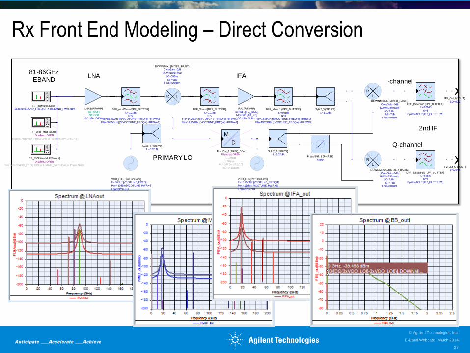
Rx Front End Modeling – Direct Conversion
LNA81-86GHz
EBAND
2nd IF
PRIMARY LO
IFAI-channel
Q-channelIL=3.02dB
Split2_1 {SPLIT2}
M
D
InDrv=13dBm
HL=0dB [zzz;0;0;0,0]DIV=4
CG=0dB
Disabled: OPENFreqDiv_1 {FREQ_DIV}
IL=3.02dBSplit2_2 {SPLIT2}
OP1dB=60dBm
NF=3dB [IFA_NF]G=20dB [IFA_GAIN]
IFA1 {RFAMP}
IL=3.02dB
Split2_3 {SPLIT2}
A=90°
PhaseShift_1 {PHASE}
Fhi=19.25GHz [(VCOTUNE_FREQ/4)+RFBW/2]
Flo=14.25GHz [(VCOTUNE_FREQ/4)-RFBW/2]
N=3IL=0.01dB
BPF_Xband1 {BPF_BUTTER}
OP1dB=10dBm
NF=5dBG=20.5dB
LNA1 {RFAMP}
Fpass=1GHz [IF2_FILTERBW]
N=3
IL=0.01dBLPF_Baseband {LPF_BUTTER}
Source2=EBAND_FREQ GHz at EBAND_PWR dBm, w Phase Noise
Disabled: OPEN
RF_PhNoise {MultiSource}
Source1=EBAND_FREQ GHz at -60 dBm, BW: 2.4 GHz
Disabled: OPEN
RF_wide {MultiSource}
Source1=EBAND_FREQ GHz at EBAND_PWR dBmRF_in {MultiSource}
ZO=50Ω
IF2_Out_I {*OUT}
Fpass=1GHz [IF2_FILTERBW]
N=3IL=0.01dB
LPF_Baseband1 {LPF_BUTTER}
R I
L
IP1dB=0dBmNF=7dB
LO=7dBm
SUM=DifferenceConvGain=0dB
DOWNMIX2BQ {MIXER_BASIC} ZO=50Ω
IF2_Out_Q {*OUT}
R I
L
IP1dB=20dBmNF=7dB
LO=7dBm
SUM=Difference
ConvGain=0dBDOWNMIX1 {MIXER_BASIC}
Fhi=19.25GHz [(VCOTUNE_FREQ/4)+RFBW/2]
Flo=14.25GHz [(VCOTUNE_FREQ/4)-RFBW/2]
N=3IL=0.01dB
BPF_Xband {BPF_BUTTER}
Fhi=86.25GHz [(5*VCOTUNE_FREQ/4)+RFBW/2]
Flo=81.25GHz [(5*VCOTUNE_FREQ/4)-RFBW/2]
N=3IL=0.01dB
BPF_mmWave {BPF_BUTTER}
EnablePN=NO
Pwr=13dBm [VCOTUNE_PWR+6]
F=67GHz [VCOTUNE_FREQ]VCO_LO3 {PwrOscillator}
EnablePN=NO
Pwr=13dBm [VCOTUNE_PWR+6]
F=16.75GHz [VCOTUNE_FREQ/4]VCO_LO6 {PwrOscillator}
R I
L
IP1dB=0dBm
NF=7dBLO=7dBm
SUM=Difference
ConvGain=0dB
DOWNMIX2BI {MIXER_BASIC}
E-Band Webcast , March 2014
© Agilent Technologies, Inc.
27
Key system questions
• Do the baseband PHY algorithms work with the RF?
• What are the root causes of each problem?
• Which domain is the best place to address these problems?
• Can you correlate measurements with simulations?
• If not, what assumptions are “baked into the results”?
? ? ? E-Band Webcast , March 2014
© Agilent Technologies, Inc.
28
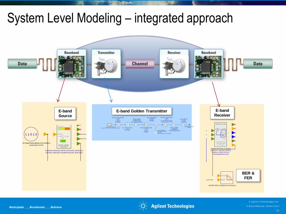
System Level Modeling – integrated approach
E-band
Source E-band Golden Transmitter
Spe c t rum A nalyzer
SpecRxIn
Spe c t rum A nalyzer
SpecRxOut
123SigRxIn
123SigRxOut
NoiseDensity
Noise_Power
Attenuation
Attenuation=54 [Atten]
Subnetwork1 {Attenuation}
1 1 0 1 0
DataPattern=PN15
B2 {DataPattern@Data Flow Models}
TEST
REF
BERFER {BER_FER@Data Flow Models}
Re
ImFc
CxEnv
E2 {EnvToCx@Data Flow Models}
Spe c t rum A nalyzer
SpecRxWnoi
ModOUT
QUADOUT
FreqPhaseQ
IAmp
InitialPhase=0°
FCarrier=81e+9Hz [FCarrier]
InputType=I/Q
RF_Link
SYS
BPSK, QPSK, ..., up to 4096-QAM8-PSK, 16-PSK, 16-APSK, 32-APSK
16-Star QAM , 32-Star-QAM, and Cus tom APSK
Data Pay loadPreambleId le
Fram e Struc ture
Spreading Code
Generator
X
D ig it a l M ode m Source
f o r L ine a r M odu lation
DSSS Sy s tem
Payload_ModType=16-QAM [Payload_ModType]
Preamble_ModType=BPSK [Preamble_ModType]
Dec ision
Dev ice
Feedward
Fi l ter-
-
Feedback
Fi l ter
Dec is ion Feedbac k Equal izer
Fas t Com putation Algori thm
CIR--->DFE c oeffic ients
D ig it a l M ode m R e ceiver
TrackingAlgorithm=LMS
FreqSync_Mode=CIR Corr
FrameSync_Algorithm=DiffCorr
{DigMod_ReceiverL_FastDFE}
R I
L
IP1dB=5dBmLO=7dBm
ConvGain=0dBMixer_1 {MIXER_BASIC}
PhaseN=(4) [-60; -80; -100; -96]dB
Pwr=7dBmF=60750MHz [3*FTXIF]LO7 {PwrOscillator}
Fhi=20375MHz [FTXIF+CS/2]
Flo=20125MHz [FTXIF-CS/2]N=3
IL=0.01dB
BPF_Butter_9 {BPF_BUTTER}
OP1dB=8dBm [RXIFOP1dB]NF=10dB [RXIFNF]
G=4dB [RXIFG]RFAmp_2 {RFAMP}
OP1dB=4dBm
NF=26.16dBG=0dB
RFAmp_5 {RFAMP}
ZO=50ΩRECEIVEROUT {*OUT}
Fhi=86.5GHz
Flo=80.5GHzN=5
IL=0.01dB
BPF_Butter_8 {BPF_BUTTER}
IP1dB=100dBm
L=1dBAttn_4 {ATTN_NonLinear}
Fhi=86GHzFlo=81GHz
N=3IL=0.01dB
BPF_Butter_6 {BPF_BUTTER}Source1=FTXRF MHz at -12 dBm, BW: CS MHzTX_IF_IN {MultiSource}
OP1dB=4dBm [RXLNAOP1dB]
NF=8dB [RXLNANF]G=22dB [RXLNAG]RFAmp_1 {RFAMP}
Spe c t rum A nalyzer
SpecRxIn
Spe c t rum A nalyzer
SpecRxOut
123SigRxIn
123SigRxOut
NoiseDensity
Noise_Power
Attenuation
Attenuation=54 [Atten]
Subnetwork1 {Attenuation}
1 1 0 1 0
DataPattern=PN15
B2 {DataPattern@Data Flow Models}
TEST
REF
BERFER {BER_FER@Data Flow Models}
Re
ImFc
CxEnv
E2 {EnvToCx@Data Flow Models}
Spe c t rum A nalyzer
SpecRxWnoi
ModOUT
QUADOUT
FreqPhaseQ
IAmp
InitialPhase=0°
FCarrier=81e+9Hz [FCarrier]
InputType=I/Q
RF_Link
SYS
BPSK, QPSK, ..., up to 4096-QAM8-PSK, 16-PSK, 16-APSK, 32-APSK
16-Star QAM , 32-Star-QAM, and Cus tom APSK
Data Pay loadPreambleId le
Fram e Struc ture
Spreading Code
Generator
X
D ig it a l M ode m Source
f o r L ine a r M odu lation
DSSS Sy s tem
Payload_ModType=16-QAM [Payload_ModType]
Preamble_ModType=BPSK [Preamble_ModType]
Dec ision
Dev ice
Feedward
Fi l ter-
-
Feedback
Fi l ter
Dec is ion Feedbac k Equal izer
Fas t Com putation Algori thm
CIR--->DFE c oeffic ients
D ig it a l M ode m R e ceiver
TrackingAlgorithm=LMS
FreqSync_Mode=CIR Corr
FrameSync_Algorithm=DiffCorr
{DigMod_ReceiverL_FastDFE}
E-band
Receiver
BER &
FER
E-Band Webcast , March 2014
© Agilent Technologies, Inc.
29
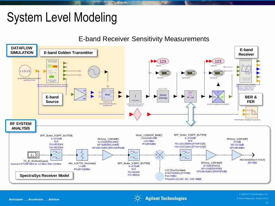
System Level Modeling
Spe c t rum A nalyzer
SpecRxIn
Spe c t rum A nalyzer
SpecRxOut
123SigRxIn
123SigRxOut
NoiseDensity
Noise_Power
Attenuation
Attenuation=54 [Atten]
Subnetwork1 {Attenuation}
1 1 0 1 0
DataPattern=PN15
B2 {DataPattern@Data Flow Models}
TEST
REF
BERFER {BER_FER@Data Flow Models}
Re
ImFc
CxEnv
E2 {EnvToCx@Data Flow Models}
Spe c t rum A nalyzer
SpecRxWnoi
ModOUT
QUADOUT
FreqPhaseQ
IAmp
InitialPhase=0°
FCarrier=81e+9Hz [FCarrier]
InputType=I/Q
RF_Link
SYS
BPSK, QPSK, ..., up to 4096-QAM8-PSK, 16-PSK, 16-APSK, 32-APSK
16-Star QAM , 32-Star-QAM, and Cus tom APSK
Data Pay loadPreambleId le
Fram e Struc ture
Spreading Code
Generator
X
D ig it a l M ode m Source
f o r L ine a r M odu lation
DSSS Sy s tem
Payload_ModType=16-QAM [Payload_ModType]
Preamble_ModType=BPSK [Preamble_ModType]
Dec ision
Dev ice
Feedward
Fi l ter-
-
Feedback
Fi l ter
Dec is ion Feedbac k Equal izer
Fas t Com putation Algori thm
CIR--->DFE c oeffic ients
D ig it a l M ode m R e ceiver
TrackingAlgorithm=LMS
FreqSync_Mode=CIR Corr
FrameSync_Algorithm=DiffCorr
{DigMod_ReceiverL_FastDFE}
E-band Receiver Sensitivity Measurements
E-band
Source
E-band
Receiver
BER &
FER
E-band Golden Transmitter
DATAFLOW
SIMULATION
R I
L
IP1dB=5dBmLO=7dBm
ConvGain=0dBMixer_1 {MIXER_BASIC}
PhaseN=(4) [-60; -80; -100; -96]dB
Pwr=7dBmF=60750MHz [3*FTXIF]LO7 {PwrOscillator}
Fhi=20375MHz [FTXIF+CS/2]
Flo=20125MHz [FTXIF-CS/2]N=3
IL=0.01dB
BPF_Butter_9 {BPF_BUTTER}
OP1dB=8dBm [RXIFOP1dB]NF=10dB [RXIFNF]
G=4dB [RXIFG]RFAmp_2 {RFAMP}
OP1dB=4dBm
NF=26.16dBG=0dB
RFAmp_5 {RFAMP}
ZO=50ΩRECEIVEROUT {*OUT}
Fhi=86.5GHz
Flo=80.5GHzN=5
IL=0.01dB
BPF_Butter_8 {BPF_BUTTER}
IP1dB=100dBm
L=1dBAttn_4 {ATTN_NonLinear}
Fhi=86GHzFlo=81GHz
N=3IL=0.01dB
BPF_Butter_6 {BPF_BUTTER}Source1=FTXRF MHz at -12 dBm, BW: CS MHzTX_IF_IN {MultiSource}
OP1dB=4dBm [RXLNAOP1dB]
NF=8dB [RXLNANF]G=22dB [RXLNAG]RFAmp_1 {RFAMP}
RF SYSTEM
ANALYSIS
SpectraSys Receiver Model
E-Band Webcast , March 2014
© Agilent Technologies, Inc.
30
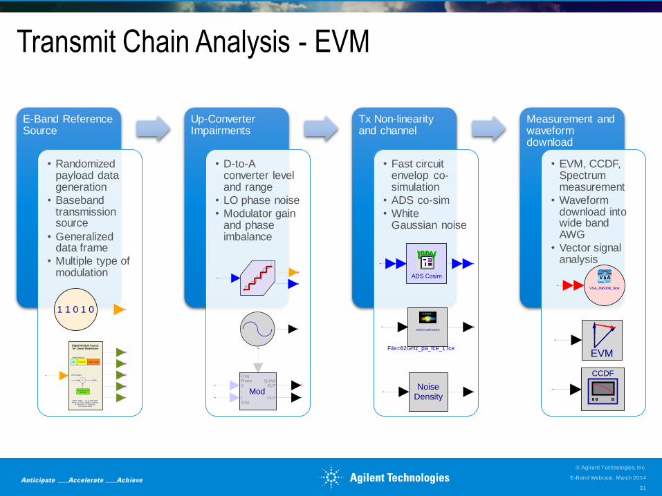
Transmit Chain Analysis - EVM
E-Band Reference Source
• Randomized payload data generation
• Baseband transmission source
• Generalized data frame
• Multiple type of modulation
Up-Converter Impairments
• D-to-A converter level and range
• LO phase noise
• Modulator gain and phase imbalance
Tx Non-linearity and channel
• Fast circuit envelop co-simulation
• ADS co-sim
• White Gaussian noise
Measurement and waveform download
• EVM, CCDF, Spectrum measurement
• Waveform download into wide band AWG
• Vector signal analysis
BPSK, QPSK, ..., up to 4096-QAM
8-PSK, 16-PSK, 16-APSK, 32-APSK16-Star QAM, 32-Star-QAM,
and Custom APSK
Data PayloadPreambleIdle
Frame Structure
Spreading CodeGenerator
X
Digital Modem Sourcefor Linear Modulation
DSSS System
ModOUT
QUADOUT
FreqPhaseQ
IAmp
NoiseDensity
FastCircuitEnvelope
File=82GHz_pa_fce_1.fce
VSA_89600B_Sink
EVM
CCDF
ADS Cosim
1 1 0 1 0
E-Band Webcast , March 2014
© Agilent Technologies, Inc.
31
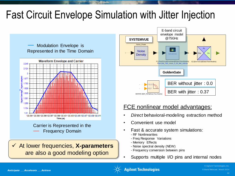
Fast Circuit Envelope Simulation with Jitter Injection
NoiseDensity
Noise_Power
Fc
CxEnv
E2 {EnvToCx@Data Flow Models}
FastCircuitEnvelope
File=LNA_75G_Vmax_0_05_BW_10G.fce
F1 {FastCircuitEnvelope@Data Flow Models}
SYSTEMVUE
E-band circuit
envelope model
@75GHz
GoldenGate
Modulation Envelope is
Represented in the Time Domain
Carrier is Represented in the
Frequency Domain
Circuit Envelope Simulation
TEST
REF
BERFER {BER_FER@Data Flow Models}
BER without jitter : 0.0
BER with jitter : 0.37
FCE nonlinear model advantages:
• Direct behavioral-modeling extraction method
• Convenient use model
• Fast & accurate system simulations: - RF Nonlinearities
- Freq Response Variations
- Memory Effects
- Noise spectral density (NEW)
- Frequency conversion between pins
• Supports multiple I/O pins and internal nodes
At lower frequencies, X-parameters
are also a good modeling option
E-Band Webcast , March 2014
© Agilent Technologies, Inc.
32
RF INTEGRATED
VERIFICATION & TEST 3
ADVANCED MODEM
TECHNOLOGIES 2
SYSTEM-LEVEL
DESIGN COCKPIT
E-BAND SYSTEM
OVERVIEW 1
HARDWARE &
MEASUREMENTS 4
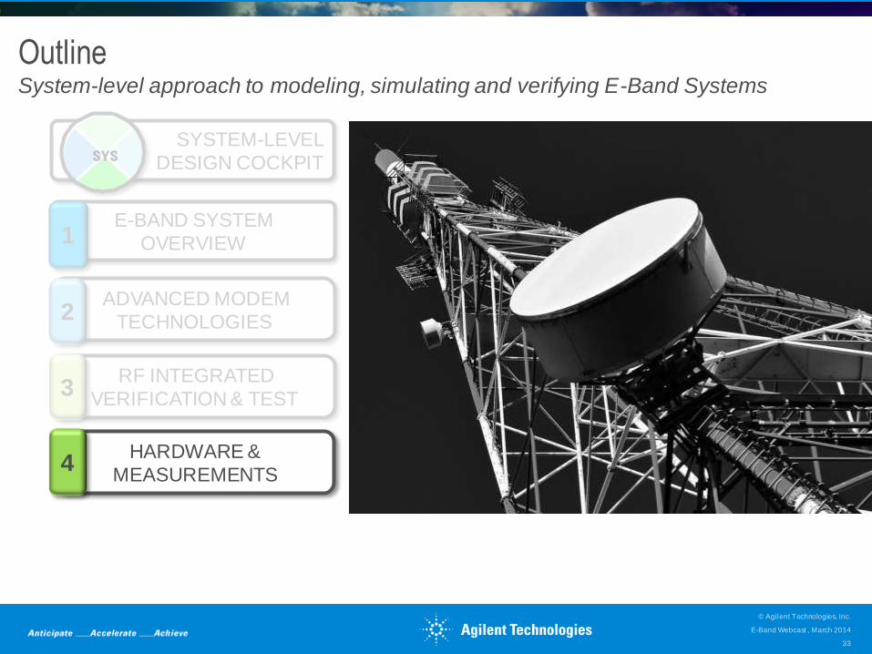
Outline System-level approach to modeling, simulating and verifying E-Band Systems
E-Band Webcast , March 2014
© Agilent Technologies, Inc.
33
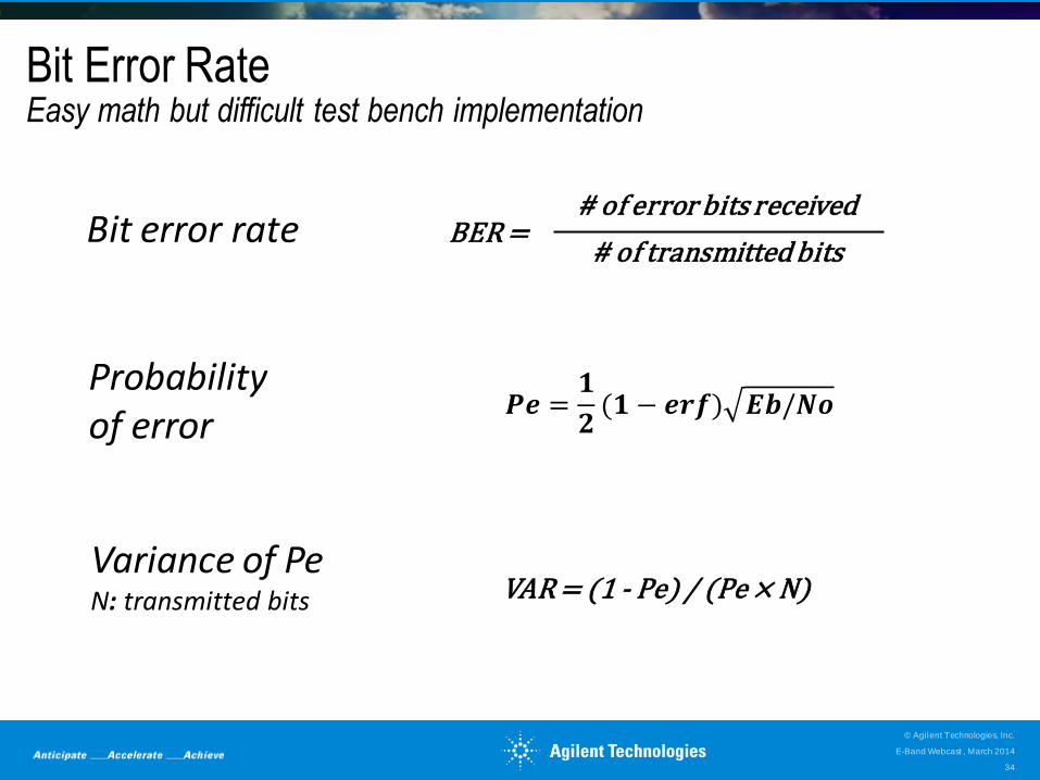
Bit Error Rate Easy math but difficult test bench implementation
𝑷𝒆 =𝟏
𝟐(𝟏 − 𝒆𝒓𝒇) 𝑬𝒃/𝑵𝒐
Probability of error
VAR = (1 - Pe) / (Pe × N) Variance of Pe N: transmitted bits
# of error bits received
# of transmitted bits Bit error rate BER =
E-Band Webcast , March 2014
© Agilent Technologies, Inc.
34
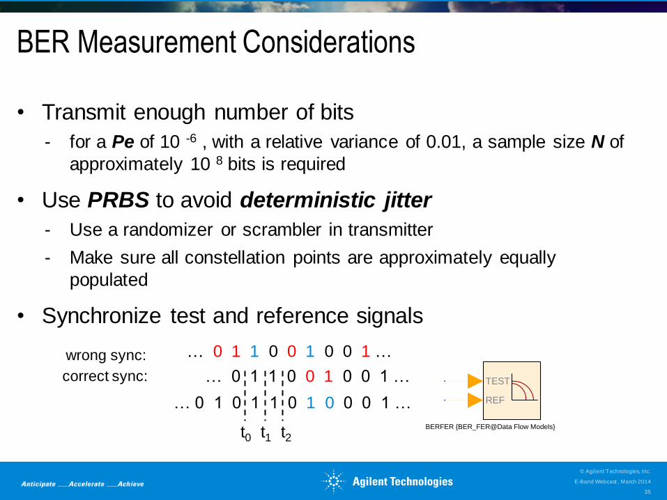
BER Measurement Considerations
• Transmit enough number of bits
- for a Pe of 10 -6 , with a relative variance of 0.01, a sample size N of
approximately 10 8 bits is required
• Use PRBS to avoid deterministic jitter
- Use a randomizer or scrambler in transmitter
- Make sure all constellation points are approximately equally
populated
• Synchronize test and reference signals
TEST
REF
BERFER {BER_FER@Data Flow Models}
… 0 1 1 0 0 1 0 0 1 …
… 0 1 0 1 1 0 1 0 0 0 1 …
t0 t1 t2
… 0 1 1 0 0 1 0 0 1 …
wrong sync:
correct sync:
E-Band Webcast , March 2014
© Agilent Technologies, Inc.
35
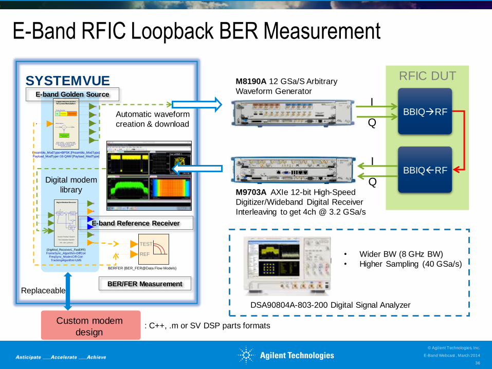
E-Band RFIC Loopback BER Measurement
• Wider BW (8 GHz BW)
• Higher Sampling (40 GSa/s)
DSA90804A-803-200 Digital Signal Analyzer
SYSTEMVUE
TEST
REF
BERFER {BER_FER@Data Flow Models}
BPSK, QPSK, ..., up to 4096-QAM
8-PSK, 16-PSK, 16-APSK, 32-APSK16-Star QAM, 32-Star-QAM,
and Custom APSK
Data PayloadPreambleIdle
Frame Structure
Spreading CodeGenerator
X
Digital Modem Sourcefor Linear Modulation
DSSS System
Payload_ModType=16-QAM [Payload_ModType]
Preamble_ModType=BPSK [Preamble_ModType]
Decision Device
FeedwardFilter
-
-
FeedbackFilter
Decision Feedback Equalizer
Fast Computation Algorithm
CIR--->DFE coefficients
Digital Modem Receiver
TrackingAlgorithm=LMS
FreqSync_Mode=CIR Corr
FrameSync_Algorithm=DiffCorr
{DigMod_ReceiverL_FastDFE}
RFIC DUT
BBIQRF
M8190A 12 GSa/S Arbitrary
Waveform Generator
I
Q Automatic waveform
creation & download
E-band Golden Source
E-band Reference Receiver
BER/FER Measurement
Custom modem
design
Replaceable
Digital modem
library
: C++, .m or SV DSP parts formats
E-Band Webcast , March 2014
© Agilent Technologies, Inc.
36
M9703A AXIe 12-bit High-Speed
Digitizer/Wideband Digital Receiver
Interleaving to get 4ch @ 3.2 GSa/s
BBIQRF I
Q
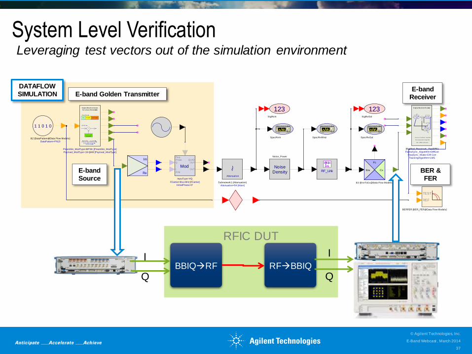
System Level Verification
Spe c t rum A nalyzer
SpecRxIn
Spe c t rum A nalyzer
SpecRxOut
123SigRxIn
123SigRxOut
NoiseDensity
Noise_Power
Attenuation
Attenuation=54 [Atten]
Subnetwork1 {Attenuation}
1 1 0 1 0
DataPattern=PN15
B2 {DataPattern@Data Flow Models}
TEST
REF
BERFER {BER_FER@Data Flow Models}
Re
ImFc
CxEnv
E2 {EnvToCx@Data Flow Models}
Spe c t rum A nalyzer
SpecRxWnoi
ModOUT
QUADOUT
FreqPhaseQ
IAmp
InitialPhase=0°
FCarrier=81e+9Hz [FCarrier]
InputType=I/Q
RF_Link
SYS
BPSK, QPSK, ..., up to 4096-QAM8-PSK, 16-PSK, 16-APSK, 32-APSK
16-Star QAM , 32-Star-QAM, and Cus tom APSK
Data Pay loadPreambleId le
Fram e Struc ture
Spreading Code
Generator
X
D ig it a l M ode m Source
f o r L ine a r M odu lation
DSSS Sy s tem
Payload_ModType=16-QAM [Payload_ModType]
Preamble_ModType=BPSK [Preamble_ModType]
Dec ision
Dev ice
Feedward
Fi l ter-
-
Feedback
Fi l ter
Dec is ion Feedbac k Equal izer
Fas t Com putation Algori thm
CIR--->DFE c oeffic ients
D ig it a l M ode m R e ceiver
TrackingAlgorithm=LMS
FreqSync_Mode=CIR Corr
FrameSync_Algorithm=DiffCorr
{DigMod_ReceiverL_FastDFE}
Leveraging test vectors out of the simulation environment
E-band
Source
E-band
Receiver
BER &
FER
E-band Golden Transmitter
DATAFLOW
SIMULATION
RFIC DUT
BBIQRF RFBBIQ I
Q
I
Q
E-Band Webcast , March 2014
© Agilent Technologies, Inc.
37
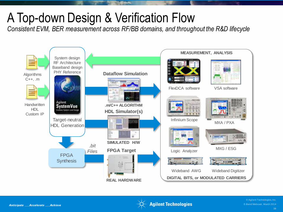
A Top-down Design & Verification Flow Consistent EVM, BER measurement across RF/BB domains, and throughout the R&D lifecycle
FPGA
Synthesis
Handwritten
HDL
Custom IP
Algorithms
C++, .m
MEASUREMENT, ANALYSIS
VSA software FlexDCA software
DIGITAL BITS, or MODULATED CARRIERS
MXG / ESG
Infiniium Scope
Logic Analyzer
MXA / PXA
Wideband AWG Wideband Digitizer
Target-neutral
HDL Generation
System design
RF Architecture
Baseband design
PHY Reference
HDL Simulator(s)
SIMULATED H/W
Dataflow Simulation
.m/C++ ALGORITHM
.bit
Files FPGA Target
REAL HARDWARE
E-Band Webcast , March 2014
© Agilent Technologies, Inc.
38
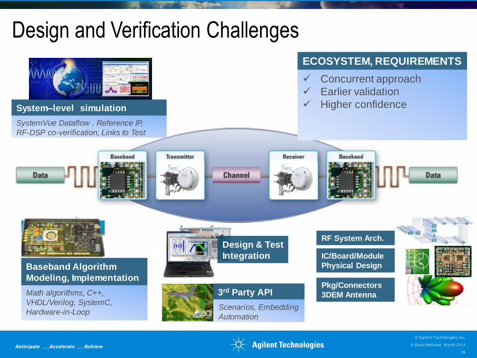
Design and Verification Challenges
SystemVue Dataflow , Reference IP,
RF-DSP co-verification, Links to Test
System–level simulation
Math algorithms, C++,
VHDL/Verilog, SystemC,
Hardware-in-Loop
Baseband Algorithm
Modeling, Implementation
Design & Test
Integration
3rd Party API
Scenarios, Embedding
Automation
RF System Arch.
IC/Board/Module
Physical Design
Pkg/Connectors
3DEM Antenna
Concurrent approach
Earlier validation
Higher confidence
ECOSYSTEM, REQUIREMENTS
E-Band Webcast , March 2014
© Agilent Technologies, Inc.
39
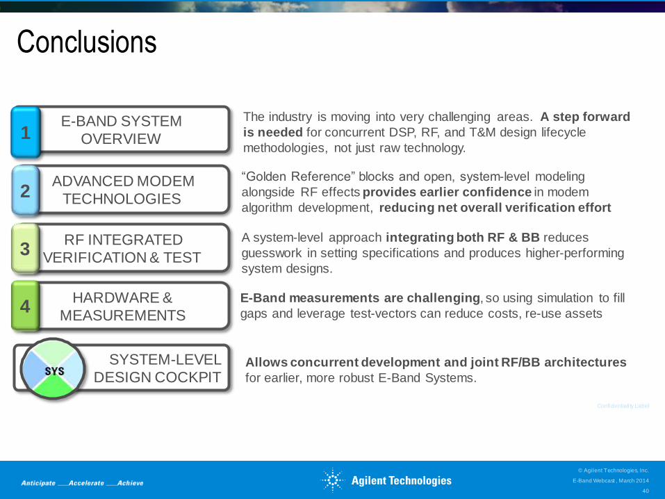
Conclusions
Confidentiality Label
Allows concurrent development and joint RF/BB architectures
for earlier, more robust E-Band Systems.
E-Band measurements are challenging, so using simulation to fill
gaps and leverage test-vectors can reduce costs, re-use assets
A system-level approach integrating both RF & BB reduces
guesswork in setting specifications and produces higher-performing
system designs.
The industry is moving into very challenging areas. A step forward
is needed for concurrent DSP, RF, and T&M design lifecycle
methodologies, not just raw technology.
“Golden Reference” blocks and open, system-level modeling
alongside RF effects provides earlier confidence in modem
algorithm development, reducing net overall verification effort
RF INTEGRATED
VERIFICATION & TEST 3
ADVANCED MODEM
TECHNOLOGIES 2
SYSTEM-LEVEL
DESIGN COCKPIT
E-BAND SYSTEM
OVERVIEW 1
HARDWARE &
MEASUREMENTS 4
E-Band Webcast , March 2014
© Agilent Technologies, Inc.
40
Questions? - Connect with Us
Visit Agilent’s websites at
• agilent.com/find/systemvue
• agilent.com/find/lte-advanced
• www.agilent.com/find/5g
to see the latest solutions that can be used for 4G and 5G
Specifically featured: W1902 Digital Modem library
• cp.literature.agilent.com/litweb/pdf/5991-3123EN.pdf
E-Band Webcast , March 2014
© Agilent Technologies, Inc.
41