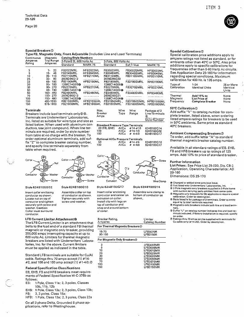
Embed Size (px)
Citation preview
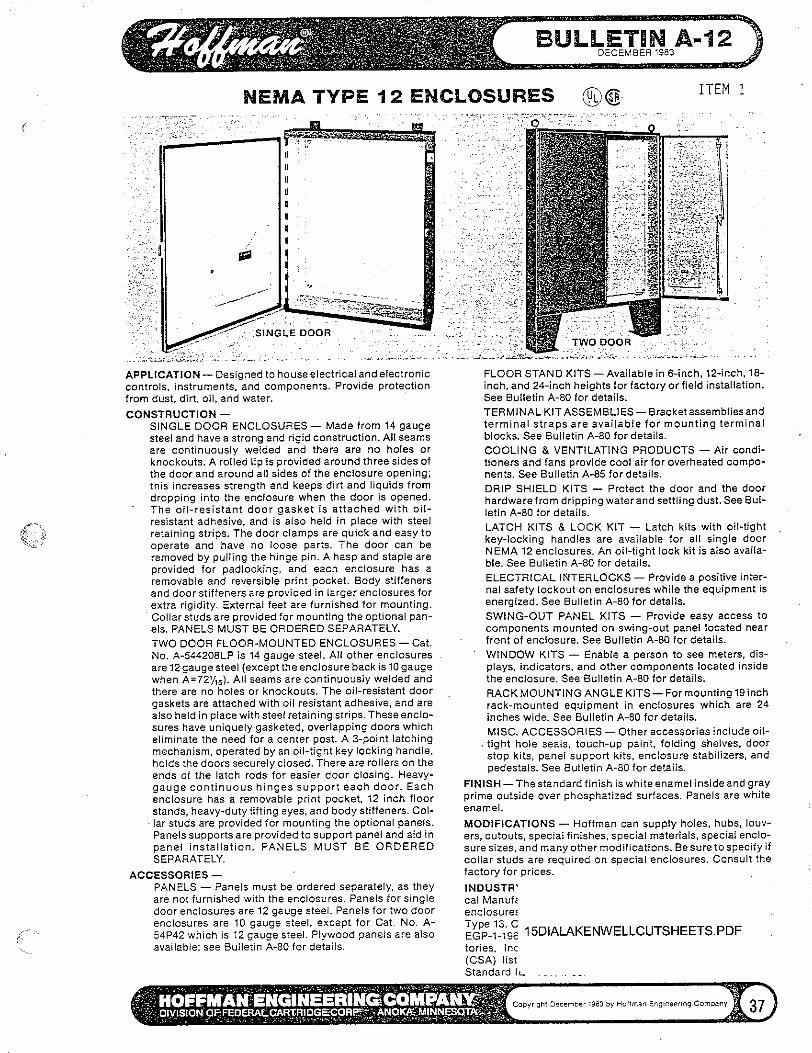
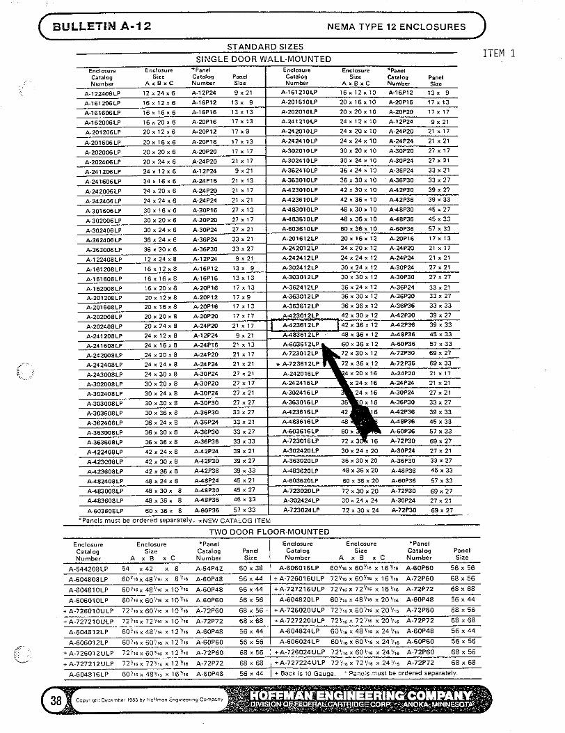
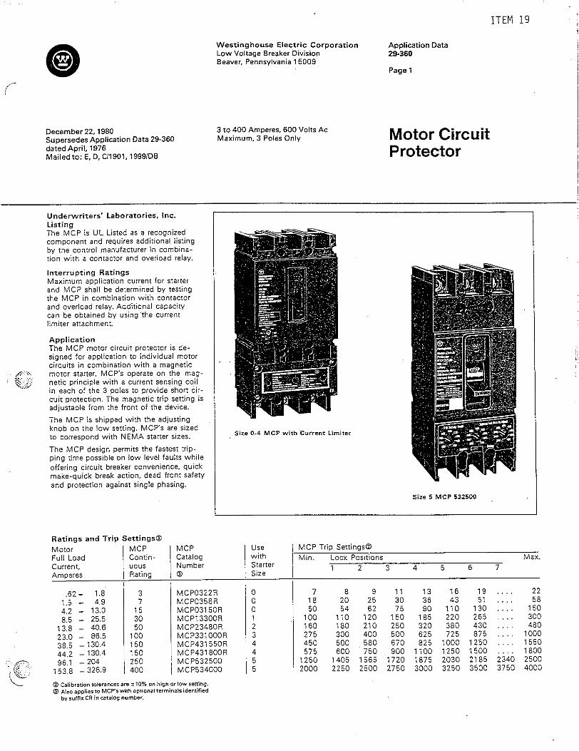
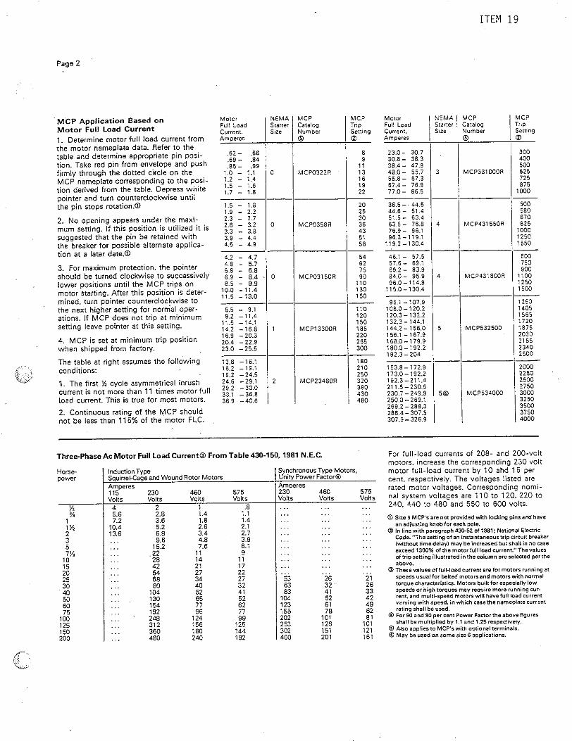
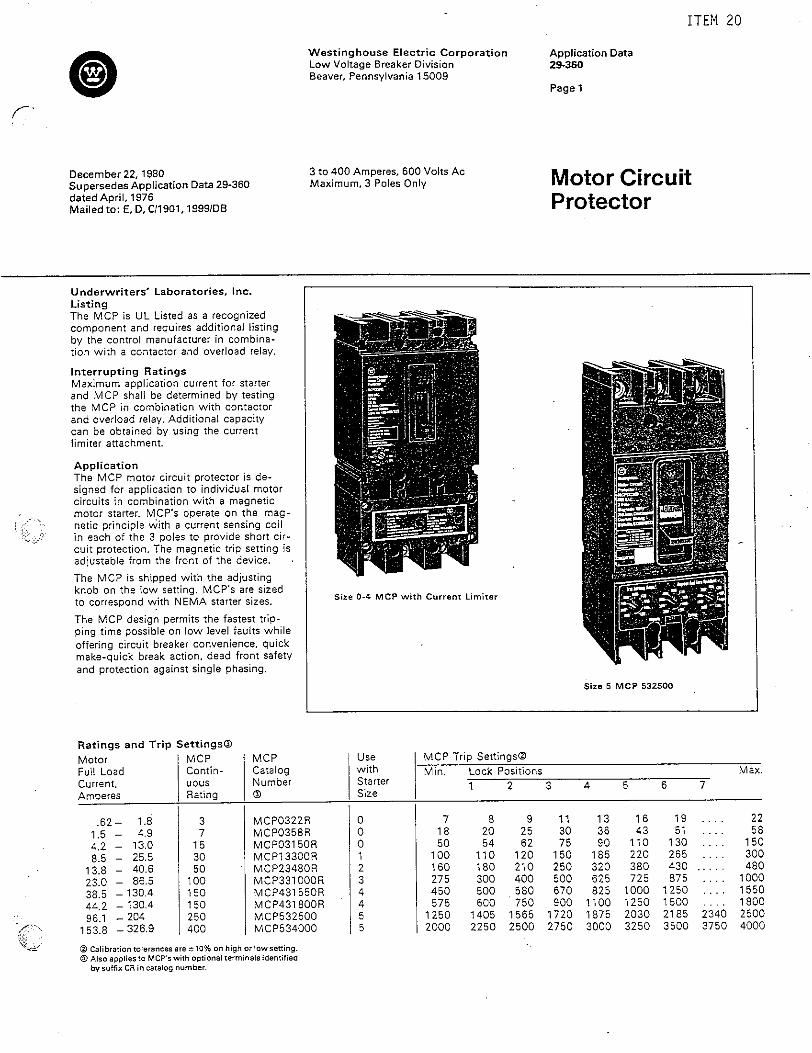
E-66 LEVEL SWITCH for water storage tank 06/03/2002 Page - 1/2
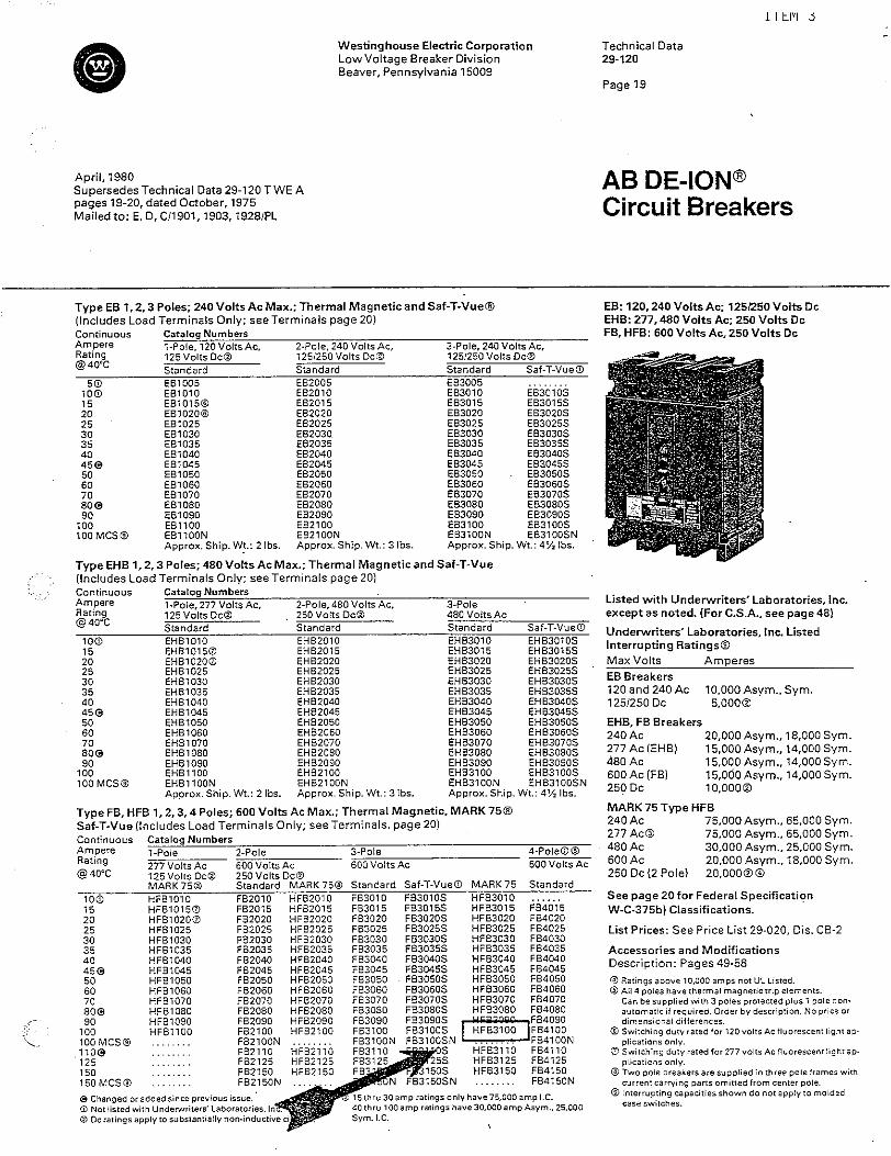
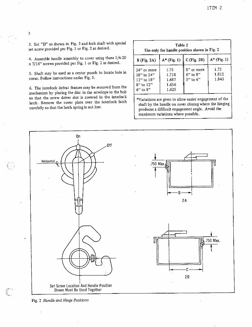
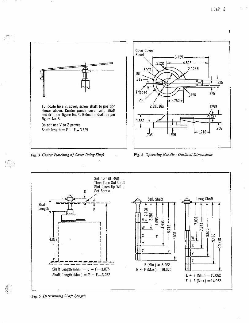
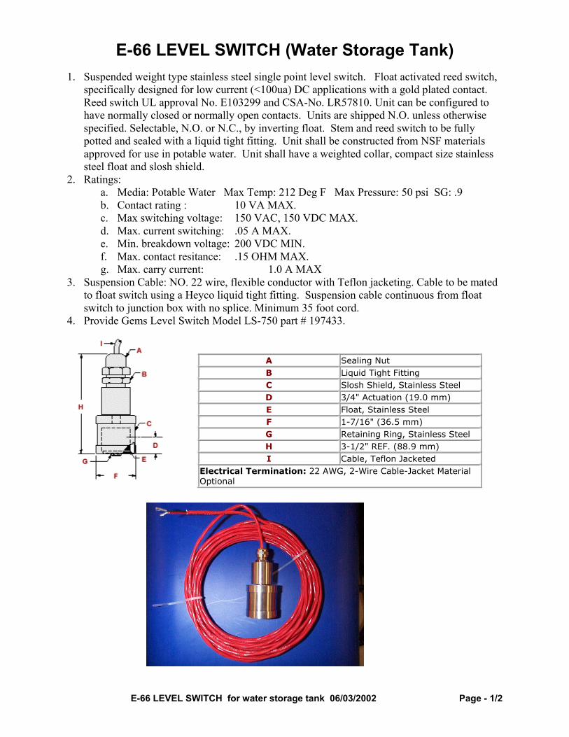
E-66 LEVEL SWITCH (Water Storage Tank) 1. Suspended weight type stainless steel single point level switch. Float activated reed switch,
specifically designed for low current (<100ua) DC applications with a gold plated contact. Reed switch UL approval No. E103299 and CSA-No. LR57810. Unit can be configured to have normally closed or normally open contacts. Units are shipped N.O. unless otherwise specified. Selectable, N.O. or N.C., by inverting float. Stem and reed switch to be fully potted and sealed with a liquid tight fitting. Unit shall be constructed from NSF materials approved for use in potable water. Unit shall have a weighted collar, compact size stainless steel float and slosh shield.
2. Ratings: a. Media: Potable Water Max Temp: 212 Deg F Max Pressure: 50 psi SG: .9 b. Contact rating : 10 VA MAX. c. Max switching voltage: 150 VAC, 150 VDC MAX. d. Max. current switching: .05 A MAX. e. Min. breakdown voltage: 200 VDC MIN. f. Max. contact resitance: .15 OHM MAX. g. Max. carry current: 1.0 A MAX
3. Suspension Cable: NO. 22 wire, flexible conductor with Teflon jacketing. Cable to be mated to float switch using a Heyco liquid tight fitting. Suspension cable continuous from float switch to junction box with no splice. Minimum 35 foot cord.
4. Provide Gems Level Switch Model LS-750 part # 197433.
A Sealing Nut B Liquid Tight Fitting C Slosh Shield, Stainless Steel D 3/4" Actuation (19.0 mm) E Float, Stainless Steel F 1-7/16" (36.5 mm) G Retaining Ring, Stainless Steel H 3-1/2" REF. (88.9 mm) I Cable, Teflon Jacketed
Electrical Termination: 22 AWG, 2-Wire Cable-Jacket Material Optional
E-66 LEVEL SWITCH for water storage tank 06/03/2002 Page - 2/2
Wetted Materials for the LS-750 part # 197433 Stainless Steel
NSF/FDA Approvals Gems P/N Description Material Approvals for material 196803 Stem, LS-750 Stainless Steel,
316L ANSI/NSF Standard 61
138341 Cable, 2 Conductor, 20 GA
Teflon FEP Jacket FDA Regulation 177.1550
198967 Water Tight Fitting , PG7 Thread, Sealcon P/N CD07ARTE
Fitting, PVDF, Cable Gland, Viton O-Ring , Viton
Fitting, FDA, CFR title21, subchapter B, §177,2510 "Polyvinylidene floride resins", Cable Gland, O-Ring, FDA, CFR title 21 177.2600
154069 Float Assembly Stainless Steel, 316L
ANSI/NSF Standard 61
196804 Cover, Slosh Shield Stainless Steel, 316L
ANSI/NSF Standard 61
196805 Slosh Shield, Tube Stainless Steel, 316L
ANSI/NSF Standard 61
15331 Retaining Clip, Push-On
Stainless Steel, 316L
ANSI/NSF Standard 61
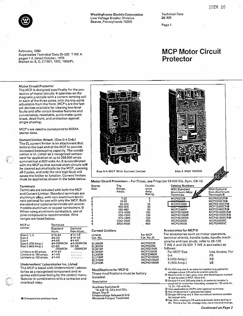
USDA Forest Service Project Specifications
05/22/01 Submersible Level Transducer 16902 - 1
SECTION 16902 SUBMERSIBLE LEVEL (PRESSURE) TRANSDUCER
1. PART 1 - GENERAL 1.01 REFERENCES
A. 16010 - General Technical Provisions. B. 16050 - Basic Methods and Materials
1.02 DESCRIPTION
A. This submersible pressure transducer shall be suitable for continuous submergence in either water or domestic sewage. The connection Junction box may have up to 100% RH condensing atmosphere.
1.03 SUBMITTALS
A. Submit shop drawings and equipment catalog data and manufacturer's installation operating and maintenance instructions for approval of the following items in accordance with Section 16010.
2. PART 2 - PRODUCTS 2.01 SUBMERSIBLE PRESSURE TRANSDUCER SPECIFICATION
A. Range: 0 – 10 PSIG = 23.1 feet of water. B. Overload: Proof Pressure: 2 times FS C. Burst Pressure: 35 times FS D. Materials Contacting Media: Transducer: 17 – 4 Stainless Steel E. Cable: FDA Approved Material in contact with water F. Weight with 32’ Cable: 20 oz. G. Electrical: Input: 7 – 35 VDC H. Output: 4 – 20 mA I. Supply Sensitivity: 0.01%FS/Volt J. Max. Loop Resistance: (Vs-7) x 50 Ohms K. Insulation Resistance: > 1000 M Ohms at 50 VDC L. Approvals: CE and UL M. Intrinsic safety: For sewage applications, sensor shall be ETL
approved Intrinsically Safe for Class 1, Groups C and D 1. Intrinsically safe transducer shall be suitable for use in conjunction with Gems Barrier
P/N 195318. 2. Entity parameters are: Voc=28VDC, Isc=89mA, Ca=1.1microfarads,
La=35.7microHenrys N. Performance:
1. Accuracy: 0.15% (Includes hysteresis, non-linearity and repeatability) 2. Long Term Drift: 0.2% FS/year (non-cumulative) 3. Zero Tolerance: 0.1% of span
USDA Forest Service Project Specifications
05/22/01 Submersible Level Transducer 16902 - 2
4. Span Tolerance: 0.1% of span 5. There shall be no allowance in design for zero and span adjustments 6. Strain gages in sensor should be produced by CVD process 7. Thermal Error: 1% FS Typical with “B” accuracy option 8. Compensated Temp: -5F to 180F 9. Operating Temp: -5F to 125F with Immersible Cable 10. Pressure Port: G1/8 female (others available) 11. Vibration: 35g peak, 5 to 2000 Hz 12. Acceleration: 100g in any direction. 0.032%FS/g for 15 psi decreasing
logarithmically to 0.0007% FS/g for 6000 psi 13. Shock: Withstands free fall to IEC 68-2-32 procedure 1 14. Transducers should meet the requirements for CE marking as detailed in EN50082-2
for susceptibility. Test methods are defined in the following test procedures: EN61000-4-2 Electrostatic Discharge +/- 4kV contact discharge +/- 8kV air discharge EN61000-4-4 Fast Burst Transients +/- 2kV 2 minutes
O. Accessories: 1. Potable water and Intrinsically Safe designs shall be compatible for use with Gems
transient protector, P/N 195319. 2. Provide Moisture protection of vent tube for potable water or Intrinsically Safe
transducer shall be accomplished using a desiccant dryer tube, Gems P/N 195316. Provide one spare desiccant dryer tube for each transducer.
P. For Water and Sewage Applications: 1. Provide Gems Sensors Inc. Model 26ETBGF1509MEGBxxx Intrinsically Safe
Transducer. Provide 33’ of cable. Q. Manufacturer
1. Transducer and accessories supplied by Gems Sensors Inc., 1 Cowles Road, Plainville, CT 06062
3. PART 3 - EXECUTION 3.01 INSTALLATION & TESTING
A. Install sensor in water tank or sewage tank as shown on drawings. Tighten compression cord grip carefully to avoid damage to sensor cable.
B. Minimum bending radius of cable: 6” C. Install vent tube to moisture trap with tube end down to keep free moisture from entering
vent tube. D. Install vent tube moisture trap, transient voltage surge suppressor, control cable lightning
arrestors as shown on drawings. E. Provide nameplates for all equipment in sensor connection J box as per 16010.
USDA Forest Service Project Specifications
05/22/01 Submersible Level Transducer 16902 - 3
F. Test sensor by putting plastic electrical tape at one-foot intervals from the bottom of the sensor and immersing the sensor in water at one foot intervals and recording the current (4-20MA) up to the maximum depth of the liquid in the tank installed. Verify that resultant current meets accuracy specification above. Replace any unit not meeting specification; re-test until accuracy specification is met. Utilize a 4-1/2 digit Fluke multi-meter or equal for testing. See 16010 for complete testing requirements.
END OF SPECIFICATIONS
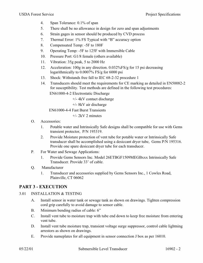
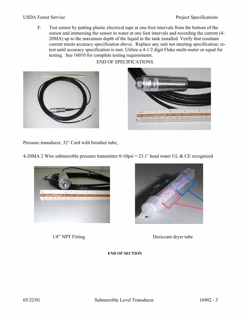
Pressure transducer, 32’ Cord with breather tube, 4-20MA 2 Wire submersible pressure transmitter 0-10psi = 23.1’ head water UL & CE recognized 1/8” NPT Fitting Desiccant dryer tube
END OF SECTION
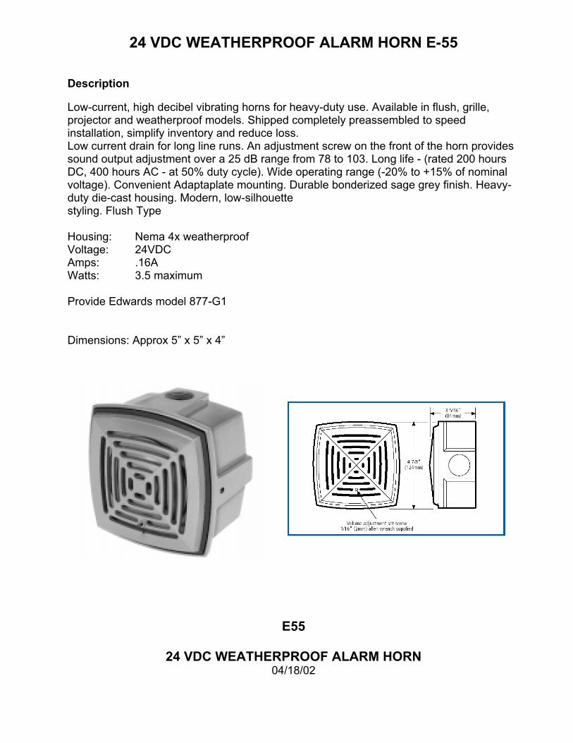
24 VDC WEATHERPROOF ALARM HORN E-55 Description Low-current, high decibel vibrating horns for heavy-duty use. Available in flush, grille, projector and weatherproof models. Shipped completely preassembled to speed installation, simplify inventory and reduce loss. Low current drain for long line runs. An adjustment screw on the front of the horn provides sound output adjustment over a 25 dB range from 78 to 103. Long life - (rated 200 hours DC, 400 hours AC - at 50% duty cycle). Wide operating range (-20% to +15% of nominal voltage). Convenient Adaptaplate mounting. Durable bonderized sage grey finish. Heavy-duty die-cast housing. Modern, low-silhouette styling. Flush Type Housing: Nema 4x weatherproof Voltage: 24VDC Amps: .16A Watts: 3.5 maximum Provide Edwards model 877-G1 Dimensions: Approx 5” x 5” x 4”
E55
24 VDC WEATHERPROOF ALARM HORN 04/18/02
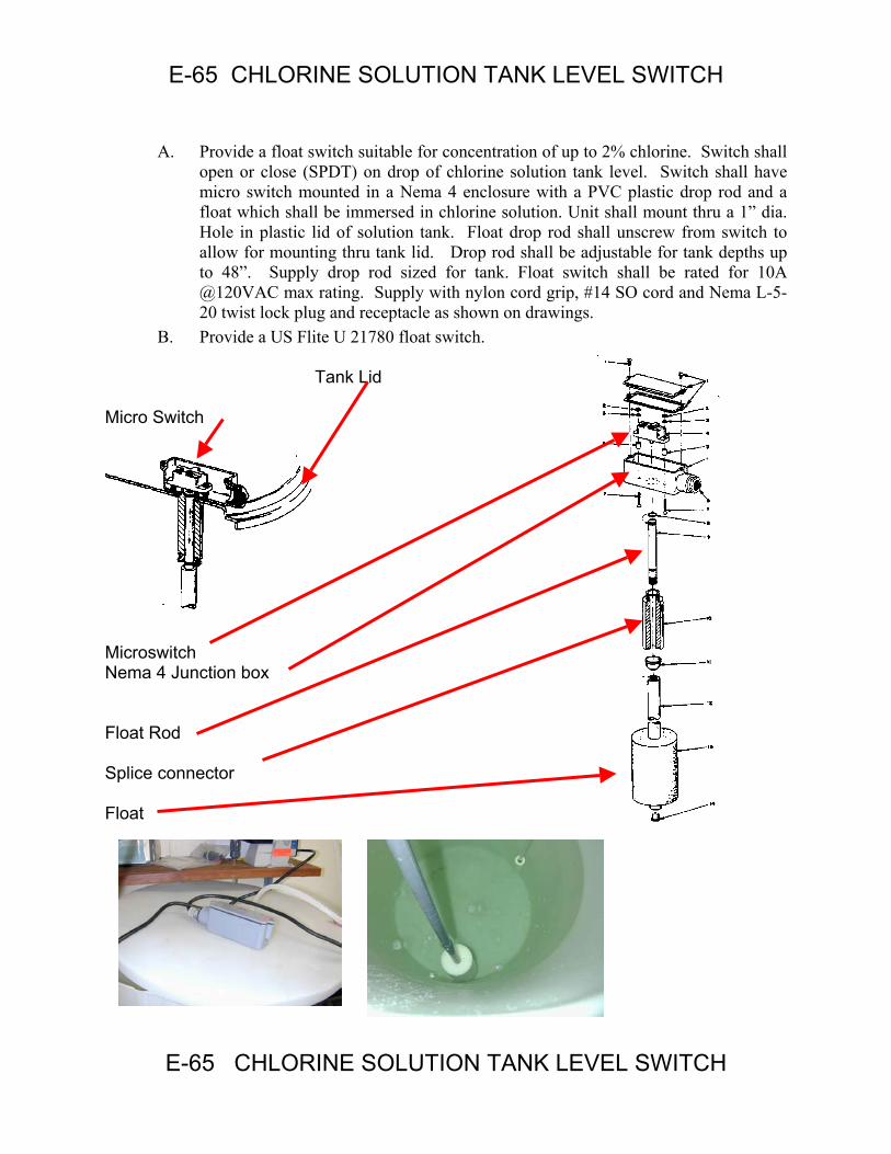
E-65 CHLORINE SOLUTION TANK LEVEL SWITCH A. Provide a float switch suitable for concentration of up to 2% chlorine. Switch shall
open or close (SPDT) on drop of chlorine solution tank level. Switch shall have micro switch mounted in a Nema 4 enclosure with a PVC plastic drop rod and a float which shall be immersed in chlorine solution. Unit shall mount thru a 1” dia. Hole in plastic lid of solution tank. Float drop rod shall unscrew from switch to allow for mounting thru tank lid. Drop rod shall be adjustable for tank depths up to 48”. Supply drop rod sized for tank. Float switch shall be rated for 10A @120VAC max rating. Supply with nylon cord grip, #14 SO cord and Nema L-5-20 twist lock plug and receptacle as shown on drawings.
B. Provide a US Flite U 21780 float switch.
Tank Lid Micro Switch
Microswitch Nema 4 Junction box Float Rod Splice connector Float
E-65 CHLORINE SOLUTION TANK LEVEL SWITCH
123
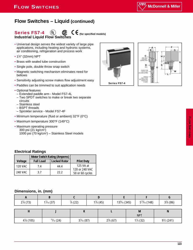
FLOW SWITCHESF
LO
WS
WIT
CH
ES
H J K L M NNPT
41⁄8 (105) 15⁄16 (24) 37⁄16 (87) 25⁄8 (67) 11⁄4 (32) 91⁄2 (241)
• Universal design serves the widest variety of large pipeapplications, including heating and hydronic systems,air conditioning, refrigeration and process work
• 11⁄4" (32mm) NPT
• Brass with sealed tube construction
• Single pole, double throw snap switch
• Magnetic switching mechanism eliminates need forbellows
• Sensitivity adjusting screw makes flow adjustment easy
• Paddles can be trimmed to suit application needs
• Optional features– Extended paddle arm - Model FS7-4L– Two SPDT switches to make or break two separate
circuits– Stainless steel– BSPT threads– Sprinkler service - Model FS7-4F
• Minimum temperature (fluid or ambient) 32°F (0°C)
• Maximum temperature 300°F (149°C)
• Maximum operating pressure300 psi (21 kg/cm2)1000 psi (70 kg/cm2) – Stainless Steel models
AGB
F
E
C
D
H J
L
K
M
N
23456
DIA. HOLEFOR ELEC.
CONNECTION
HEX.
PADDLE FOR1-1/4" & 1-1/2"
(32 & 40mm) TEES
PADDLEFOR 2" TO 5"
(50-125mm) PIPEPacked loose
in carton.Series FS7-4
Flow Switches – Liquid (continued)
Series FS7-4Industrial Liquid Flow Switches
Dimensions, in. (mm)
A B C D E F G
27⁄8 (73) 17⁄16 (37) 7⁄8 (22) 13⁄4 (45) 139⁄16 (345) 513⁄16 (148) 33⁄8 (86)
Electrical RatingsMotor Switch Rating (Amperes)
Voltage Full Load Locked Rotor Pilot Duty
120 VAC 7.4 44.4 125 VA at
240 VAC 3.7 22.2120 or 240 VAC50 or 60 cycles
®
®
(for specified models)
124
FLOW SWITCHES
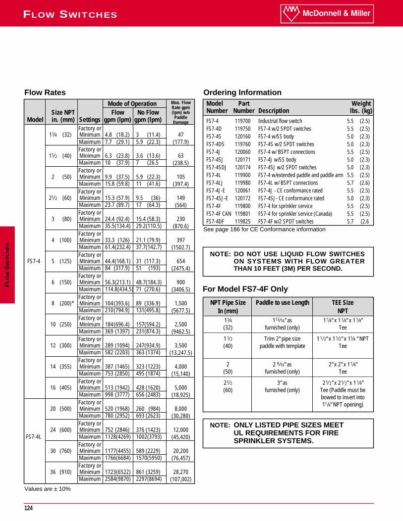
Ordering InformationModel Part WeightNumber Number Description lbs. (kg)FS7-4 119700 Industrial flow switch 5.5 (2.5)FS7-4D 119750 FS7-4 w/2 SPDT switches 5.5 (2.5)FS7-4S 120160 FS7-4 w/SS body 5.0 (2.3)FS7-4DS 119760 FS7-4S w/2 SPDT switches 5.0 (2.3)FS7-4J 120060 FS7-4 w/ BSPT connections 5.5 (2.5)FS7-4SJ 120171 FS7-4J w/SS body 5.0 (2.3)FS7-4SDJ 120174 FS7-4SJ w/2 SPDT switches 5.0 (2.3)FS7-4L 119900 FS7-4 w/extended paddle and paddle arm 5.5 (2.5)FS7-4LJ 119980 FS7-4L w/ BSPT connections 5.7 (2.6)FS7-4J-E 120061 FS7-4J - CE conformance rated 5.5 (2.5)FS7-4SJ-E 120172 FS7-4SJ- CE conformance rated 5.0 (2.3)FS7-4F 119800 FS7-4 for sprinkler service 5.5 (2.5)FS7-4F CAN 119801 FS7-4 for sprinkler service (Canada) 5.5 (2.5)FS7-4DF 119825 FS7-4F w/2 SPDT switches 5.7 (2.6
Flow RatesMode of Operation
Size NPT Flow No FlowModel in. (mm) Settings gpm (lpm) gpm (lpm)
Factory or11⁄4 (32) Minimum 4.8 (18.2) 3 (11.4) 47
Maximum 7.7 (29.1) 5.9 (22.3) (177.9)Factory or
11⁄2 (40) Minimum 6.3 (23.8) 3.6 (13.6) 63Maximum 10 (37.9) 7 (26.5 (238.5)Factory or
2 (50) Minimum 9.9 (37.5) 5.9 (22.3) 105Maximum 15.8 (59.8) 11 (41.6) (397.4)Factory or
21⁄2 (60) Minimum 15.3 (57.9) 9.5 (36) 149Maximum 23.7 (89.7) 17 (64.3) (564)Factory or
3 (80) Minimum 24.4 (92.4) 15.4 (58.3) 230Maximum 35.5(134.4) 29.2(110.5) (870.6)Factory or
4 (100) Minimum 33.3 (126) 21.1 (79.9) 397Maximum 61.4(232.4) 37.7(142.7) (1502.7)Factory or
FS7-4 5 (125) Minimum 44.4(168.1) 31 (117.3) 654Maximum 84 (317.9) 51 (193) (2475.4)Factory or
6 (150) Minimum 56.3(213.1) 48.7(184.3) 900Maximum 114.8(434.5) 71 (270.6) (3406.5)Factory or
8 (200)* Minimum 104(393.6) 89 (336.9) 1,500Maximum 210(794.9) 131(495.8) (5677.5)Factory or
10 (250) Minimum 184(696.4) 157(594.2) 2,500Maximum 369 (1397) 231(874.3) (9462.5)Factory or
12 (300) Minimum 289 (1094) 247(934.9) 3,500Maximum 582 (2203) 363 (1374) (13,247.5)Factory or
14 (355) Minimum 387 (1465) 323 (1223) 4,000Maximum 753 (2850) 495 (1874) (15,140)Factory or
16 (405) Minimum 513 (1942) 428 (1620) 5,000Maximum 998 (3777) 656 (2483) (18,925)Factory or
20 (500) Minimum 520 (1968) 260 (984) 8,000Maximum 780 (2952) 693 (2623) (30,280)Factory or
24 (600) Minimum 752 (2846) 376 (1423) 12,000FS7-4L Maximum 1128(4269) 1002(3793) (45,420)
Factory or30 (760) Minimum 1177(4455) 589 (2229) 20,200
Maximum 1766(6684) 1570(5950) (76,457)Factory or
36 (910) Minimum 1723(6522) 861 (3259) 28,270Maximum 2584(9870) 2297(8694) (107,002)
Values are ± 10%
FL
OW
SW
ITC
HE
S
NOTE: DO NOT USE LIQUID FLOW SWITCHESON SYSTEMS WITH FLOW GREATERTHAN 10 FEET (3M) PER SECOND.
NPT Pipe Size Paddle to use Length TEE SizeIn (mm) NPT
11⁄4 113 ⁄16" as 11⁄4" x 11⁄4" x 11⁄4" (32) furnished (only) Tee
11⁄2 Trim 2" pipe size 11 ⁄2" x 11⁄2" x 11⁄4 " NPT (40) paddle with template Tee
2 2 9 ⁄16" as 2" x 2" x 11⁄4" (50) furnished (only) Tee
21⁄2 3" as 21⁄2" x 21⁄2" x 11⁄4" (60) furnished (only) Tee (Paddle must be
bowed to insert into 11/4" NPT opening)
For Model FS7-4F Only
NOTE: ONLY LISTED PIPE SIZES MEET UL REQUIREMENTS FOR FIRE SPRINKLER SYSTEMS.
Max. Flow Rate gpm (lpm) w/o
Paddle Damage
See page 186 for CE Conformance information
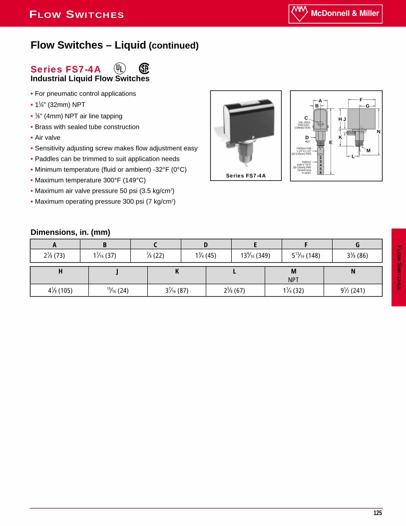
125
FLOW SWITCHESF
LO
WS
WIT
CH
ES
H J K L M NNPT
41⁄8 (105) 15⁄16 (24) 37⁄16 (87) 25⁄8 (67) 11⁄4 (32) 91⁄2 (241)
• For pneumatic control applications
• 11⁄4" (32mm) NPT
• 1⁄8" (4mm) NPT air line tapping
• Brass with sealed tube construction
• Air valve
• Sensitivity adjusting screw makes flow adjustment easy
• Paddles can be trimmed to suit application needs
• Minimum temperature (fluid or ambient) -32°F (0°C)
• Maximum temperature 300°F (149°C)
• Maximum air valve pressure 50 psi (3.5 kg/cm2)
• Maximum operating pressure 300 psi (7 kg/cm2)
Series FS7-4A
Flow Switches – Liquid (continued)
Series FS7-4AIndustrial Liquid Flow Switches
Dimensions, in. (mm)
A B C D E F G
27⁄8 (73) 17⁄16 (37) 7⁄8 (22) 13⁄4 (45) 139⁄16 (349) 513⁄16 (148) 33⁄8 (86)
®
®
AGB
F
E
C
D
H J
L
K
M
N
23456
DIA. HOLEFOR ELEC.
CONNECTION
HEX.
PADDLE FOR1-1/4" & 1-1/2"
(32 & 40mm) TEES
PADDLEFOR 2" TO 5"
(50-125mm) PIPEPacked loose
in carton.
126
FLOW SWITCHES
Ordering InformationModel Part WeightNumber Number Description lbs. (kg)
FS7-4A 119710 Industrial flow switch w/air valve 5.5 (2.5)
Flow RatesPipe Mode of Operation
Size NPT Flow No Flowin. (mm) Settings gpm (lpm) gpm (lpm)
Factory or
11⁄4 (32) Minimum 4.8 (18.2) 3 (11.4)Maximum 7.7 (29.1) 5.9 (22.3) ( 177.9)
Factory or11⁄2 (40) Minimum 6.3 (23.8) 3.6 (13.6)
Maximum 10 (37.9) 7 (26.5) (238.5)
Factory or2 (50) Minimum 9.9 (37.5) 5.9 (22.3)
Maximum 15.8 (59.8) 11 (41.6) ( 397.4)
Factory or21⁄2 (65) Minimum 15.3 (57.9) 9.5 (36)
Maximum 23.7 (89.7) 17 (64.3) (564)
Factory or3 (80) Minimum 24.4 (92.4) 15.4 (58.3)
Maximum 35.5 (134.4) 29.2 (110.5) (870.6)
Factory or4 (100) Minimum 33.3 (126) 21.1 (79.9)
Maximum 61.4 (232.4) 37.7 (142.7) (1502.7)
Factory or5 (125) Minimum 44.4 (168.1) 31 (117.3)
Maximum 84 (317.9) 51 (193) (2475.4)
Factory or6 (150) Minimum 56.3 (213.1) 48.7 (184.3)
Maximum 114.8 (434.5) 71 (270.6) (3406.5)
Factory or8 (200)* Minimum 104 (393.6) 89 (336.9)
Maximum 210 (794.9) 131 (495.8) (5677.5)
Factory or10 (250)* Minimum 184 (696.4) 157 (594.2)
Maximum 369 (1397) 231 (874.3) (9462.5)
Factory or12 (300)* Minimum 289 (1094) 247 (934.9)
Maximum 582 (2203) 363 (1374) (13,247.5)
Factory or14 (355)* Minimum 387 (1465) 323 (1223)
Maximum 753 (2850) 495 (1874) (15,140)
Factory or16 (405)* Minimum 513 (1942) 428 (1620)
Maximum 998 (3777) 656 (2483) (18,925)Values are ± 10%* Equipped with a 6" (152mm) paddle
FL
OW
SW
ITC
HE
S
NOTE: DO NOT USE LIQUID FLOW SWITCHESON SYSTEMS WITH FLOW GREATERTHAN 10 FEET (3M) PER SECOND.
47
63
105
149
230
397
654
900
1,500
2,500
3,500
4,000
5,000
Max. Flow Rate gpm (lpm) w/o
Paddle Damage
127
FLOW SWITCHESF
LO
WS
WIT
CH
ES
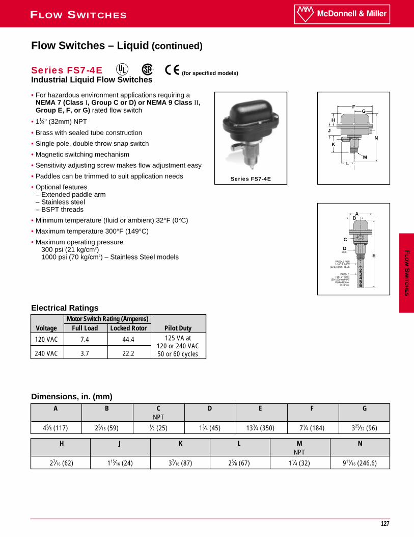
• For hazardous environment applications requiring aNEMA 7 (Class I, Group C or D) or NEMA 9 Class II,Group E, F, or G) rated flow switch
• 11⁄4" (32mm) NPT
• Brass with sealed tube construction
• Single pole, double throw snap switch
• Magnetic switching mechanism
• Sensitivity adjusting screw makes flow adjustment easy
• Paddles can be trimmed to suit application needs
• Optional features– Extended paddle arm– Stainless steel– BSPT threads
• Minimum temperature (fluid or ambient) 32°F (0°C)
• Maximum temperature 300°F (149°C)
• Maximum operating pressure300 psi (21 kg/cm2)1000 psi (70 kg/cm2) – Stainless Steel models
GF
H
K
L
J
N
M
AB
E
C
D
23456
HEX.
PADDLE FOR1-1/4" & 1-1/2"
(32 & 40mm) TEES
PADDLEFOR 2" TO 6"
(50-150mm) PIPEPacked loose
in carton.
Series FS7-4E
Flow Switches – Liquid (continued)
Series FS7-4EIndustrial Liquid Flow Switches
®
®
H J K L M NNPT
27⁄16 (62) 115⁄16 (24) 37⁄16 (87) 25⁄8 (67) 11⁄4 (32) 911⁄16 (246.6)
Dimensions, in. (mm)A B C D E F G
NPT
45⁄8 (117) 25⁄16 (59) 1⁄2 (25) 13⁄4 (45) 133⁄4 (350) 71⁄4 (184) 325⁄32 (96)
Electrical RatingsMotor Switch Rating (Amperes)
Voltage Full Load Locked Rotor Pilot Duty
120 VAC 7.4 44.4 125 VA at
240 VAC 3.7 22.2120 or 240 VAC50 or 60 cycles
(for specified models)
128
FLOW SWITCHES
Ordering InformationModel Part WeightNumber Number Description lbs. (kg)
FS7-4E 120100 FS7-4 w/NEMA 7 & 9 enclosure 12.3 (5.6)
FS7-4EJ 120135 FS7-4E w/BSPT connections 12.7 (5.8)FS7-4EL 120150 FS7-4E w/extended paddle 12.3 (5.6)
& paddle armFS7-4ELJ 120158 FS7-4EL w/BSPT connections 12.7 (5.8)FS7-4SE 120175 FS7-4S w/NEMA 7 & 9 enclosure 11.7 (5.3)FS7-4SEJ 120186 FS7-4SE w/BSPT connections 12.0 (5.4)FS7-4EJ-E 120136 FS7-4EJ - CE conformance rated 12.7 (5.8)
Flow Rates
Values are ± 10%* Equipped with a 6" (152mm) paddle
FL
OW
SW
ITC
HE
S
NOTE: DO NOT USE LIQUID FLOW SWITCHESON SYSTEMS WITH FLOW GREATERTHAN 10 FEET (3M) PER SECOND.
47
63
105
149
230
397
654
900
1,500
2,500
3,500
4,000
5,000
Pipe Mode of OperationSize NPT Flow No Flowin. (mm) Settings gpm (lpm) gpm (lpm)
Factory or
11⁄4 (32) Minimum 4.8 (18.2) 3 (11.4)Maximum 7.7 (29.1) 5.9 (22.3) (177.9)
Factory or11⁄2 (40) Minimum 6.3 (23.8) 3.6 (13.6)
Maximum 10 (37.9) 7 (26.5) (238.5)
Factory or2 (50) Minimum 9.9 (37.5) 5.9 (22.3)
Maximum 15.8 (59.8) 11 (41.6) (397.4)
Factory or21⁄2 (65) Minimum 15.3 (57.9) 9.5 (36)
Maximum 23.7 (89.7) 17 (64.3) (564)
Factory or3 (80) Minimum 24.4 (92.4) 15.4 (58.3)
Maximum 35.5 (134.4) 29.2 (110.5) (870.6)
Factory or4 (100) Minimum 33.3 (126) 21.1 (79.9)
Maximum 61.4 (232.4) 37.7 (142.7) (1502.7)
Factory or5 (125) Minimum 44.4 (168.1) 31 (117.3)
Maximum 84 (317.9) 51 (193) (2475.4)
Factory or6 (150) Minimum 56.3 (213.1) 48.7 (184.3)
Maximum 114.8 (434.5) 71 (270.6) (3406.5)
Factory or8 (200)* Minimum 104 (393.6) 89 (336.9)
Maximum 210 (794.9) 131 (495.8) (5677.5)
Factory or10 (250)* Minimum 184 (696.4) 157 (594.2)
Maximum 369 (1397) 231 (874.3) (9462.5)
Factory or12 (300)* Minimum 289 (1094) 247 (934.9)
Maximum 582 (2203) 363 (1374) (13,247.5)
Factory or14 (355)* Minimum 387 (1465) 323 (1223)
Maximum 753 (2850) 495 (1874) (15,140)
Factory or16 (405)* Minimum 513 (1942) 428 (1620)
Maximum 998 (3777) 656 (2483) (18,925)
Max. Flow Rate gpm (lpm) w/o
Paddle Damage
See page 186 for CE Conformance information
129
FLOW SWITCHESF
LO
WS
WIT
CH
ES
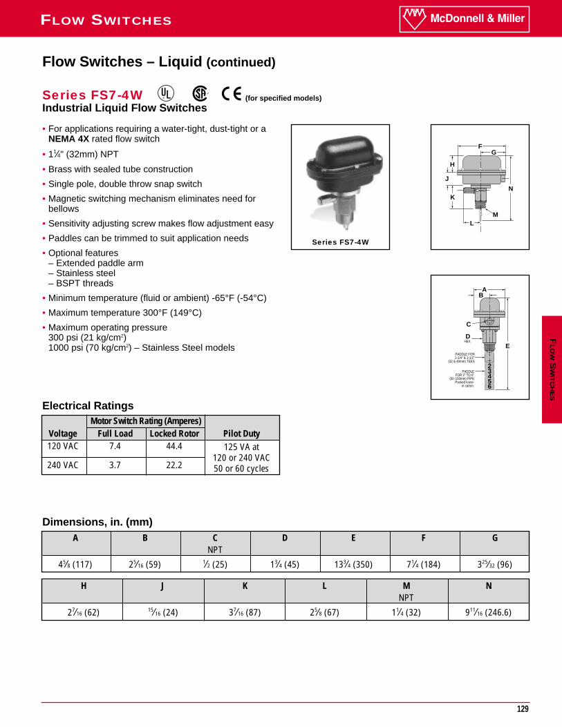
• For applications requiring a water-tight, dust-tight or aNEMA 4X rated flow switch
• 11⁄4" (32mm) NPT
• Brass with sealed tube construction
• Single pole, double throw snap switch
• Magnetic switching mechanism eliminates need forbellows
• Sensitivity adjusting screw makes flow adjustment easy
• Paddles can be trimmed to suit application needs
• Optional features– Extended paddle arm– Stainless steel– BSPT threads
• Minimum temperature (fluid or ambient) -65°F (-54°C)
• Maximum temperature 300°F (149°C)
• Maximum operating pressure300 psi (21 kg/cm2)1000 psi (70 kg/cm2) – Stainless Steel models
GF
H
K
L
J
N
M
AB
E
C
D
23456
HEX.
PADDLE FOR1-1/4" & 1-1/2"
(32 & 40mm) TEES
PADDLEFOR 2" TO 6"
(50-150mm) PIPEPacked loose
in carton.
Series FS7-4W
Flow Switches – Liquid (continued)
Series FS7-4WIndustrial Liquid Flow Switches
H J K L M NNPT
27⁄16 (62) 15⁄16 (24) 37⁄16 (87) 25⁄8 (67) 11⁄4 (32) 911⁄16 (246.6)
Dimensions, in. (mm)A B C D E F G
NPT
45⁄8 (117) 25⁄16 (59) 1⁄2 (25) 13⁄4 (45) 133⁄4 (350) 71⁄4 (184) 325⁄32 (96)
Electrical RatingsMotor Switch Rating (Amperes)
Voltage Full Load Locked Rotor Pilot Duty120 VAC 7.4 44.4 125 VA at
240 VAC 3.7 22.2120 or 240 VAC50 or 60 cycles
®
®
(for specified models)
130
FLOW SWITCHES
Ordering InformationFlow Rates
Values are ± 10%* Equipped with a 6" (152mm) paddle
FL
OW
SW
ITC
HE
S
NOTE: DO NOT USE LIQUID FLOW SWITCHESON SYSTEMS WITH FLOW GREATERTHAN 10 FEET (3M) PER SECOND.
Pipe Mode of OperationSize NPT Flow No Flowin. (mm) Settings gpm (lpm) gpm (lpm)
Factory or
11⁄4 (32) Minimum 4.8 (18.2) 3 (11.4)Maximum 7.7 (29.1) 5.9 (22.3) ( 177.9)
Factory or11⁄2 (40) Minimum 6.3 (23.8) 3.6 (13.6)
Maximum 10 (37.9) 7 (26.5) (238.5)
Factory or2 (50) Minimum 9.9 (37.5) 5.9 (22.3)
Maximum 15.8 (59.8) 11 (41.6) (397.4)
Factory or21⁄2 (65) Minimum 15.3 (57.9) 9.5 (36)
Maximum 23.7 (89.7) 17 (64.3) (564)
Factory or3 (80) Minimum 24.4 (92.4) 15.4 (58.3)
Maximum 35.5 (134.4) 29.2 (110.5) (870.6)
Factory or4 (100) Minimum 33.3 (126) 21.1 (79.9)
Maximum 61.4 (232.4) 37.7 (142.7) (1502.7)
Factory or5 (125) Minimum 44.4 (168.1) 31 (117.3)
Maximum 84 (317.9) 51 (193) (2475.4)
Factory or6 (150) Minimum 56.3 (213.1) 48.7 (184.3)
Maximum 114.8 (434.5) 71 (270.6) (3406.5)
Factory or8 (200)* Minimum 104 (393.6) 89 (336.9)
Maximum 210 (794.9) 131 (495.8) (5677.5)
Factory or10 (250)* Minimum 184 (696.4) 157 (594.2)
Maximum 369 (1397) 231 (874.3) (9462.5)
Factory or12 (300)* Minimum 289 (1094) 247 (934.9)
Maximum 582 (2203) 363 (1374) (13,247.5)
Factory or14 (355)* Minimum 387 (1465) 323 (1223)
Maximum 753 (2850) 495 (1874) (15,140)
Factory or16 (405)* Minimum 513 (1942) 428 (1620)
Maximum 998 (3777) 656 (2483) ( 18,925)
47
63
105
149
230
397
654
900
1,500
2,500
3,500
4,000
5,000
Max. Flow Rate gpm (lpm) w/o
Paddle Damage
See page 186 for CE Conformance information
Model Part WeightNumber Number Description lbs. (kg)
FS7-4W 120201 FS7-4 w/NEMA 4X enclosure 12.3 (5.6)FS7-4SW 120191 FS7-4W w/SS body 11.7 (5.3)FS7-4WJ 120261 FS7-4W w/BSPT connections 12.3 (5.6)FS7-4SWJ 120197 FS7-4SW w/BSPT connections 11.7 (5.3)FS7-4WL 120301 FS7-4W w/extended paddle 12.7 (5.8)
& paddle armFS7-4WLJ 120361 FS7-4WL w/BSPT connections 12.7 (5.8)FS7-4WJ-E 120262 FS7-4WJ - CE conformance rated 12.7 (5.8)
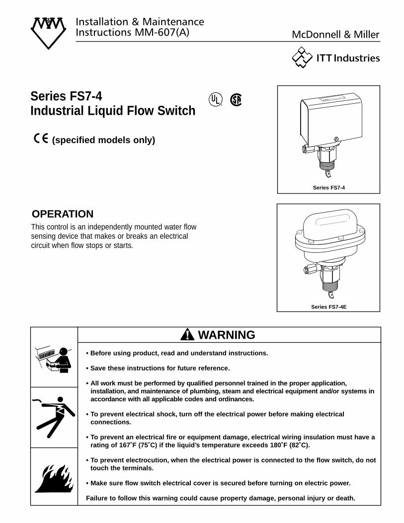
Series FS7-4Industrial Liquid Flow Switch
Installation & MaintenanceInstructions MM-607(A)
®
OPERATIONThis control is an independently mounted water flowsensing device that makes or breaks an electricalcircuit when flow stops or starts.
• Before using product, read and understand instructions.
• Save these instructions for future reference.
• All work must be performed by qualified personnel trained in the proper application,installation, and maintenance of plumbing, steam and electrical equipment and/or systems inaccordance with all applicable codes and ordinances.
• To prevent electrical shock, turn off the electrical power before making electricalconnections.
• To prevent an electrical fire or equipment damage, electrical wiring insulation must have a rating of 167˚F (75˚C) if the liquid’s temperature exceeds 180˚F (82˚C).
• To prevent electrocution, when the electrical power is connected to the flow switch, do not touch the terminals.
• Make sure flow switch electrical cover is secured before turning on electric power.
Failure to follow this warning could cause property damage, personal injury or death.
WARNINGCAUTION
! WARNING
Series FS7-4
Series FS7-4E
(specified models only)
CE Circuit Rating7.4 (7.4)/120~ 0.3/120=3.7 (3.7)/240~ 0.15/240=
2
Maximum Liquid Pressure:300 psi (21 kg/cm2) (All models except “S”)1000 psi (70 kg/cm2) (“S” models )
Liquid Temperature Range (TL):32 - 300˚F (0 - 149˚C) (All models except “W”)-65 - 300˚F (-54 - 149˚C) (“W” models)
Ambient Temperature Range (TS):32 - 120˚F (0 - 49˚C)(All models except “W”)-65 - 300˚F (-54 - 149˚C) (“W” models)
Electrical Enclosure Rating:Nema Type 1 (IP 21) (All models except “E” and “W”)Nema Type 4X (IP 56) (“W” models)Nema Type 7 and 9 (“E” models)
Maximum Velocity:10ft/sec (3M/sec)
Pipe Connection Thread Size:11/4” NPT (All models except “J”)11/4” BSPT (“J” models)
Models that meet CE Conformance:FS7-4EJ-EFS7-4J-EFS7-4SJ-EFS7-4WJ-E
• This Control: is for continuous operationsis not electronichas Type 1C action (micro interruption on operation)
• LVD 73/23/EEC
• EMC 89/33/EECFor applications with loads between 14mA and 3.7Amps, power factors exceeding 0.65, an anticipated
system switch operation rate of less than 5 times perminute, and any one cycle greater than 3 seconds onand 3 seconds off.
Additional suppression may be required for applica-tions outside these ranges.
• Declaration of ConformityAvailable on request.
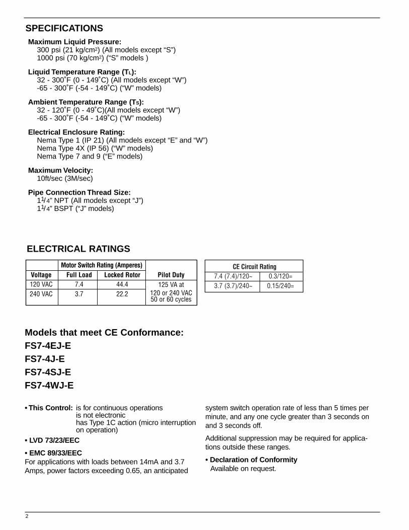
SPECIFICATIONS
Motor Switch Rating (Amperes)Voltage Full Load Locked Rotor Pilot Duty120 VAC 7.4 44.4 125 VA at240 VAC 3.7 22.2 120 or 240 VAC
50 or 60 cycles
ELECTRICAL RATINGS
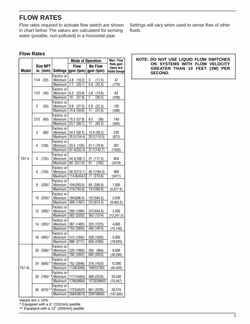
FLOW RATESFlow rates required to activate flow switch are shownin chart below. The values are calculated for sensingwater (potable, non-polluted) in a horizontal pipe.
Settings will vary when used to sense flow of otherfluids.
3
NOTE: DO NOT USE LIQUID FLOW SWITCHESON SYSTEMS WITH FLOW VELOCITYGREATER THAN 10 FEET (3M) PERSECOND.
Flow RatesMode of Operation
Size NPT Flow No FlowModel in. (mm) Settings gpm (lpm) gpm (lpm)
Factory or11⁄4 (32) Minimum 4.8 (18.2) 3 (11.4) 47
Maximum 7.7 (29.1) 5.9 (22.3) (178)Factory or
11⁄2 (40) Minimum 6.3 (23.8) 3.6 (13.6) 63Maximum 10 (37.9) 7 (26.5) (239)Factory or
2 (50) Minimum 9.9 (37.5) 5.9 (22.3) 105Maximum 15.8 (59.8) 11 (41.6) (398)Factory or
21⁄2 (60) Minimum 15.3 (57.9) 9.5 (36) 149Maximum 23.7 (89.7) 17 (64.3) (565)Factory or
3 (80) Minimum 24.4 (92.4) 15.4 (58.3) 230Maximum 35.5(134.4) 29.2(110.5) (872)Factory or
4 (100) Minimum 33.3 (126) 21.1 (79.9) 397Maximum 61.4(232.4) 37.7(142.7) (1505)Factory or
FS7-4 5 (125) Minimum 44.4(168.1) 31 (117.3) 654Maximum 84 (317.9) 51 (193) (2479)Factory or
6 (150) Minimum 56.3(213.1) 48.7(184.3) 900Maximum 114.8(434.5) 71 (270.6) (3411)Factory or
8 (200)* Minimum 104(393.6) 89 (336.9) 1,500Maximum 210(794.9) 131(495.8) (5,677.5)Factory or
10 (250)* Minimum 184(696.4) 157(594.2) 2,500Maximum 369 (1397) 231(874.3) (9,462.5)Factory or
12 (300)* Minimum 289 (1094) 247(934.9) 3,500Maximum 582 (2203) 363 (1374) (13,247.5)Factory or
14 (355)* Minimum 387 (1465) 323 (1223) 4,000Maximum 753 (2850) 495 (1874) (15,140)Factory or
16 (405)* Minimum 513 (1942) 428 (1620) 5,000Maximum 998 (3777) 656 (2483) (18,925)Factory or
20 (500)** Minimum 520 (1968) 260 (984) 8,000Maximum 780 (2952) 693 (2623) (30,280)Factory or
24 (600)** Minimum 752 (2846) 376 (1423) 12,000FS7-4L Maximum 1128(4269) 1002(3793) (45,420)
Factory or30 (760)** Minimum 1177(4455) 589 (2229) 20,200
Maximum 1766(6684) 1570(59842) (76,457)Factory or
36 (910)** Minimum 1723(6522) 861 (3259) 28,270Maximum 2584(9870) 2297(8694) (107,002)
Values are ± 10%* Equipped with a 6" (152mm) paddle** Equipped with a 12" (304mm) paddle
Max. FlowRate gpm(lpm) w/o
Paddle Damage
(25mm)
1"
6"(152mm)
12"(152mm)
23
4
5
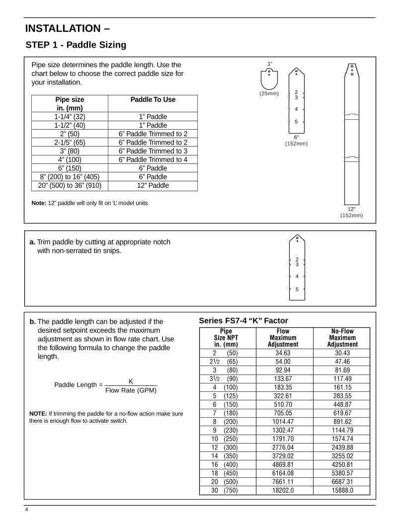
INSTALLATION –
STEP 1 - Paddle Sizing
4
23
4
5
a. Trim paddle by cutting at appropriate notchwith non-serrated tin snips.
b. The paddle length can be adjusted if thedesired setpoint exceeds the maximumadjustment as shown in flow rate chart. Usethe following formula to change the paddlelength.
Pipe size determines the paddle length. Use thechart below to choose the correct paddle size foryour installation.
Pipe size Paddle To Usein. (mm)
1-1/4” (32) 1” Paddle1-1/2” (40) 1” Paddle
2” (50) 6” Paddle Trimmed to 22-1/5” (65) 6” Paddle Trimmed to 2
3” (80) 6” Paddle Trimmed to 34” (100) 6” Paddle Trimmed to 46” (150) 6” Paddle
8” (200) to 16” (405) 6” Paddle20” (500) to 36” (910) 12” Paddle
Note: 12” paddle will only fit on ‘L’ model units
Pipe Flow No-FlowSize NPT Maximum Maximumin. (mm) Adjustment Adjustment2 (50) 34.63 30.43
21/2 (65) 54.00 47.463 (80) 92.94 81.69
31/2 (90) 133.67 117.494 (100) 183.35 161.155 (125) 322.61 283.556 (150) 510.70 448.877 (180) 705.05 619.678 (200) 1014.47 891.629 (230) 1302.47 1144.7910 (250) 1791.70 1574.7412 (300) 2776.04 2439.8814 (350) 3729.02 3255.0216 (400) 4869.81 4250.8118 (450) 6164.08 5380.5720 (500) 7661.11 6687.3130 (750) 18202.0 15888.0
Series FS7-4 “K” Factor
Paddle Length = K_______________Flow Rate (GPM)
NOTE: If trimming the paddle for a no-flow action make surethere is enough flow to activate switch.
1" MAX(25mm)
Paddle Arm
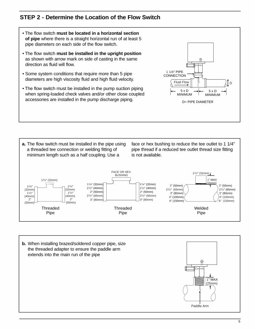
STEP 2 - Determine the Location of the Flow Switch
5
Fluid Flow D
1 1/4" PIPECONNECTION
5 x DMINIMUM
5 x DMINIMUM
D= PIPE DIAMETER
• The flow switch must be located in a horizontal sectionof pipe where there is a straight horizontal run of at least 5pipe diameters on each side of the flow switch.
• The flow switch must be installed in the upright positionas shown with arrow mark on side of casting in the samedirection as fluid will flow.
• Some system conditions that require more than 5 pipe diameters are high viscosity fluid and high fluid velocity.
• The flow switch must be installed in the pump suction pipingwhen spring-loaded check valves and/or other close coupledaccessories are installed in the pump discharge piping.
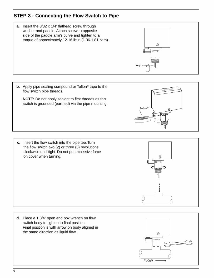
a. The flow switch must be installed in the pipe using a threaded tee connection or welding fitting of minimum length such as a half coupling. Use a
face or hex bushing to reduce the tee outlet to 1 1/4”pipe thread if a reduced tee outlet thread size fittingis not available.
b. When installing brazed/soldered copper pipe, size the threaded adapter to ensure the paddle arm extends into the main run of the pipe
2"(50mm)
11/4"(32mm)
11/2"(40mm)
11/4"(32mm)
2"(50mm)
11/2"(40mm)
11/4" (32mm)
FACE OR HEX.BUSHING
2" (50mm)
3" (80mm)
2" (50mm)
3" (80mm)
11/4" (32mm) 11/4" (32mm) 11/2" (40mm) 11/2" (40mm)
21/2" (65mm) 21/2" (65mm)
ThreadedPipe
ThreadedPipe
WeldedPipe
2" (50mm)
3" (80mm)
1" MAX(25mm)
4" (100mm) 6" (150mm)
2" (50mm)
3" (80mm) 4" (100mm)6" (150mm)
21/2" (65mm) 21/2" (65mm)
11/4" (32mm)
6
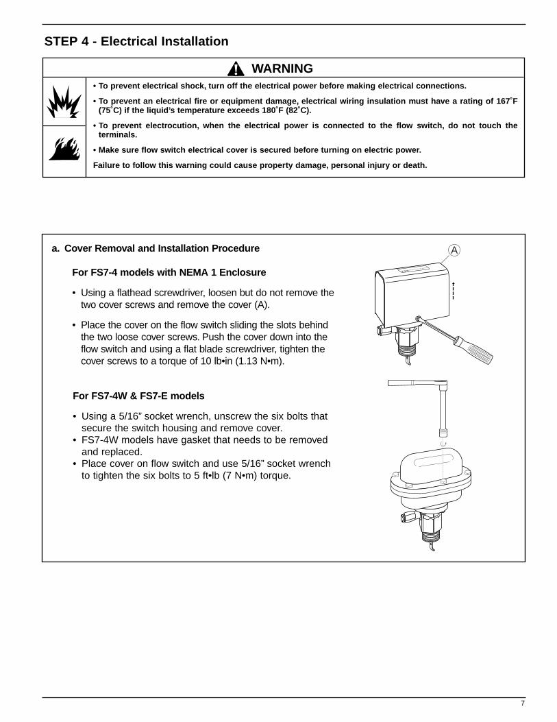
STEP 3 - Connecting the Flow Switch to Pipe
c. Insert the flow switch into the pipe tee. Turn the flow switch two (2) or three (3) revolutions clockwise until tight. Do not put excessive force on cover when turning.
FLOW
d. Place a 1 3/4” open end box wrench on flow switch body to tighten to final position.Final position is with arrow on body aligned in the same direction as liquid flow.
a. Insert the 8/32 x 1/4” flathead screw through washer and paddle. Attach screw to opposite side of the paddle arm’s curve and tighten to a torque of approximately 12-16 lb•in (1.36-1.81 N•m).
b. Apply pipe sealing compound or Teflon® tape to the flow switch pipe threads.
NOTE: Do not apply sealant to first threads as this switch is grounded (earthed) via the pipe mounting.
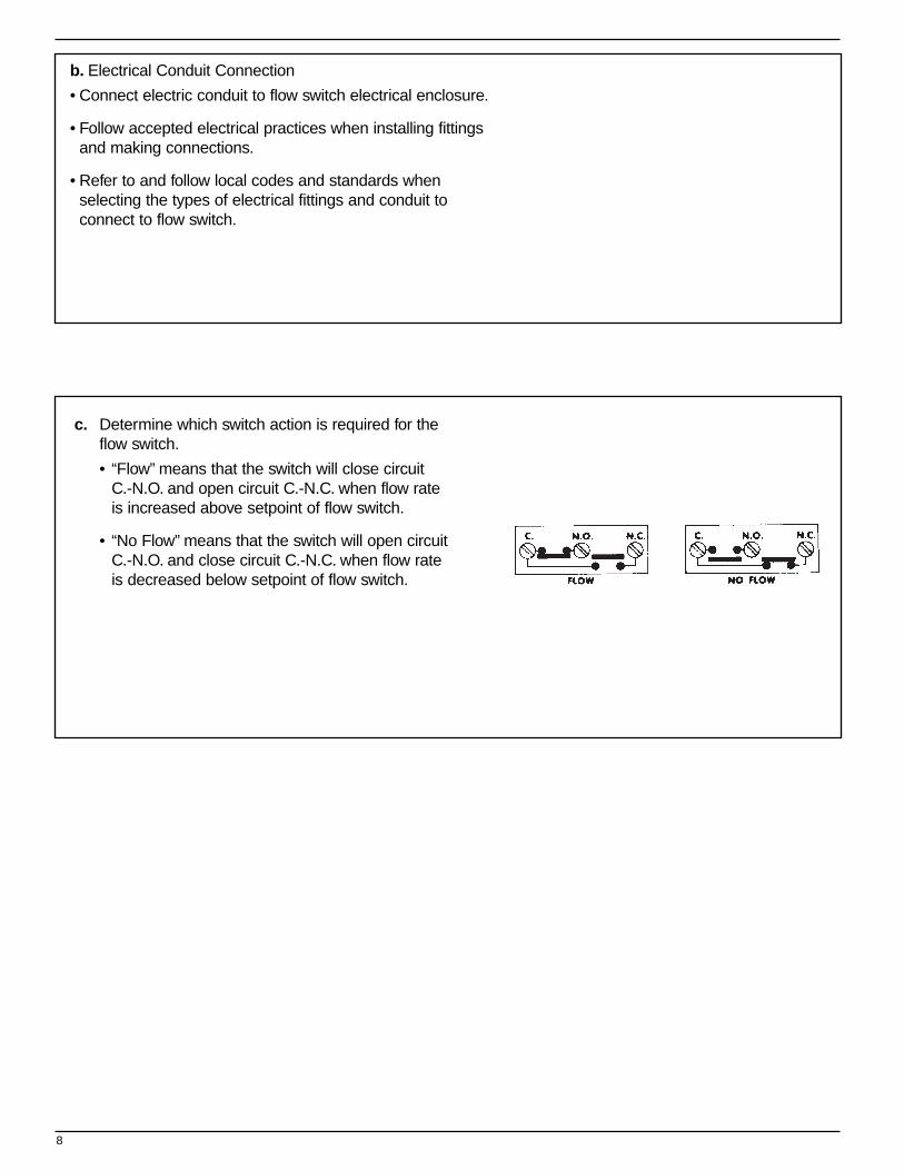
Aa. Cover Removal and Installation Procedure
For FS7-4 models with NEMA 1 Enclosure
• Using a flathead screwdriver, loosen but do not remove thetwo cover screws and remove the cover (A).
• Place the cover on the flow switch sliding the slots behindthe two loose cover screws. Push the cover down into theflow switch and using a flat blade screwdriver, tighten thecover screws to a torque of 10 lb•in (1.13 N•m).
For FS7-4W & FS7-E models
• Using a 5/16” socket wrench, unscrew the six bolts thatsecure the switch housing and remove cover.
• FS7-4W models have gasket that needs to be removedand replaced.
• Place cover on flow switch and use 5/16” socket wrenchto tighten the six bolts to 5 ft•lb (7 N•m) torque.
STEP 4 - Electrical Installation
• To prevent electrical shock, turn off the electrical power before making electrical connections.
• To prevent an electrical fire or equipment damage, electrical wiring insulation must have a rating of 167˚F(75˚C) if the liquid’s temperature exceeds 180˚F (82˚C).
• To prevent electrocution, when the electrical power is connected to the flow switch, do not touch the terminals.
• Make sure flow switch electrical cover is secured before turning on electric power.
Failure to follow this warning could cause property damage, personal injury or death.
7
! WARNING
8
c. Determine which switch action is required for the flow switch.
• “Flow” means that the switch will close circuit C.-N.O. and open circuit C.-N.C. when flow rate is increased above setpoint of flow switch.
• “No Flow” means that the switch will open circuit C.-N.O. and close circuit C.-N.C. when flow rate is decreased below setpoint of flow switch.
b. Electrical Conduit Connection
• Connect electric conduit to flow switch electrical enclosure.
• Follow accepted electrical practices when installing fittings and making connections.
• Refer to and follow local codes and standards when selecting the types of electrical fittings and conduit to connect to flow switch.
a. Place cover on flow switch and turn on power. Initiate fluid flow through the system. Observe the device being activated by the flow switch to determine if device is operating as required.
b. Turn off fluid flow to determine if device is operating as required.
c. Repeat initiating and turning off fluid flow several times to test flow switch and device for proper operation.- If operating as required, put system into service.- If not operating as required, flow switch may need
to be adjusted. OFF
ON
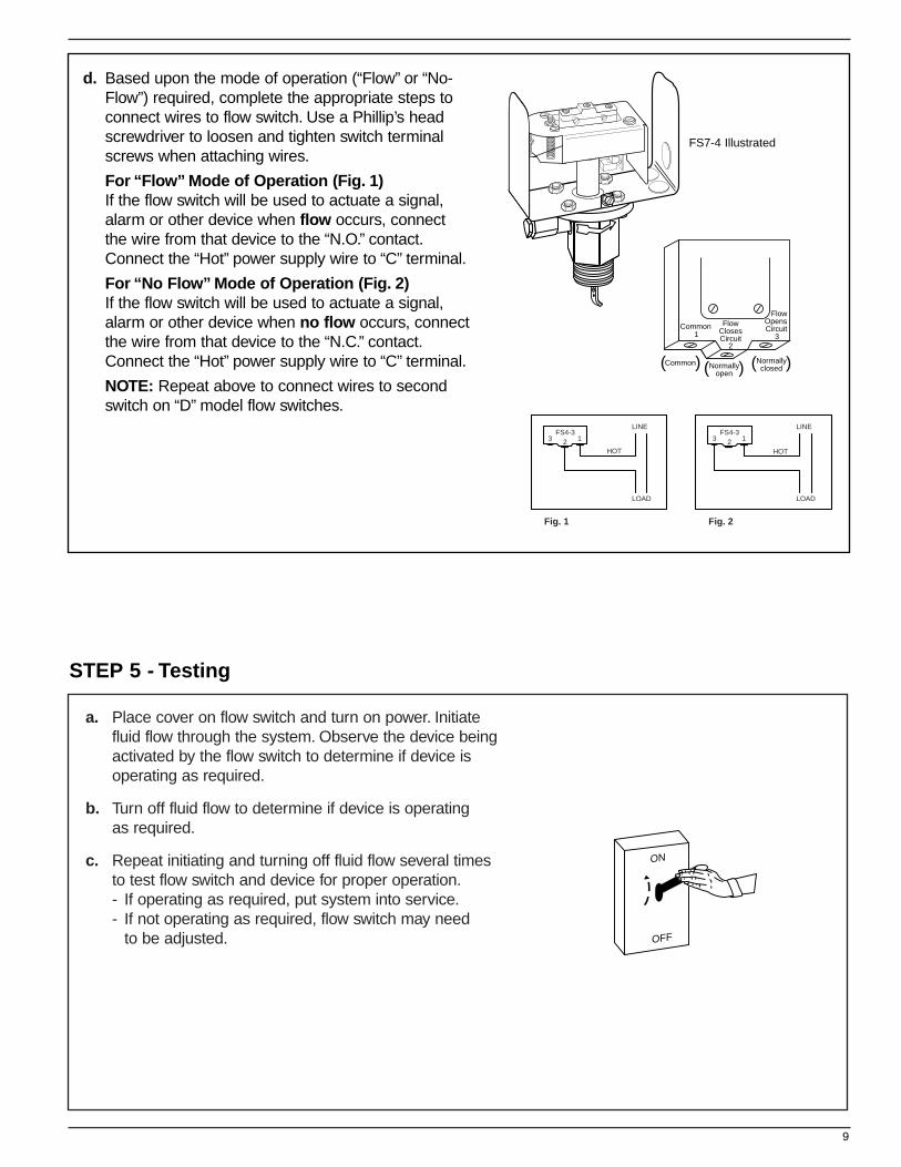
d. Based upon the mode of operation (“Flow” or “No-Flow”) required, complete the appropriate steps to connect wires to flow switch. Use a Phillip’s head screwdriver to loosen and tighten switch terminal screws when attaching wires.
For “Flow” Mode of Operation (Fig. 1)If the flow switch will be used to actuate a signal, alarm or other device when flow occurs, connect the wire from that device to the “N.O.” contact.Connect the “Hot” power supply wire to “C” terminal.
For “No Flow” Mode of Operation (Fig. 2)If the flow switch will be used to actuate a signal, alarm or other device when no flow occurs, connect the wire from that device to the “N.C.” contact.Connect the “Hot” power supply wire to “C” terminal.
NOTE: Repeat above to connect wires to second switch on “D” model flow switches.
STEP 5 - Testing
9
FlowOpensCircuit
Normallyclosed
3Common
1Flow
ClosesCircuit
2
( (Normallyopen( (Common( (
FS4-3LINE
LOAD
Fig. 1
HOT
3 12FS4-3
LINE
LOAD
Fig. 2
HOT
3 12
FS7-4 Illustrated
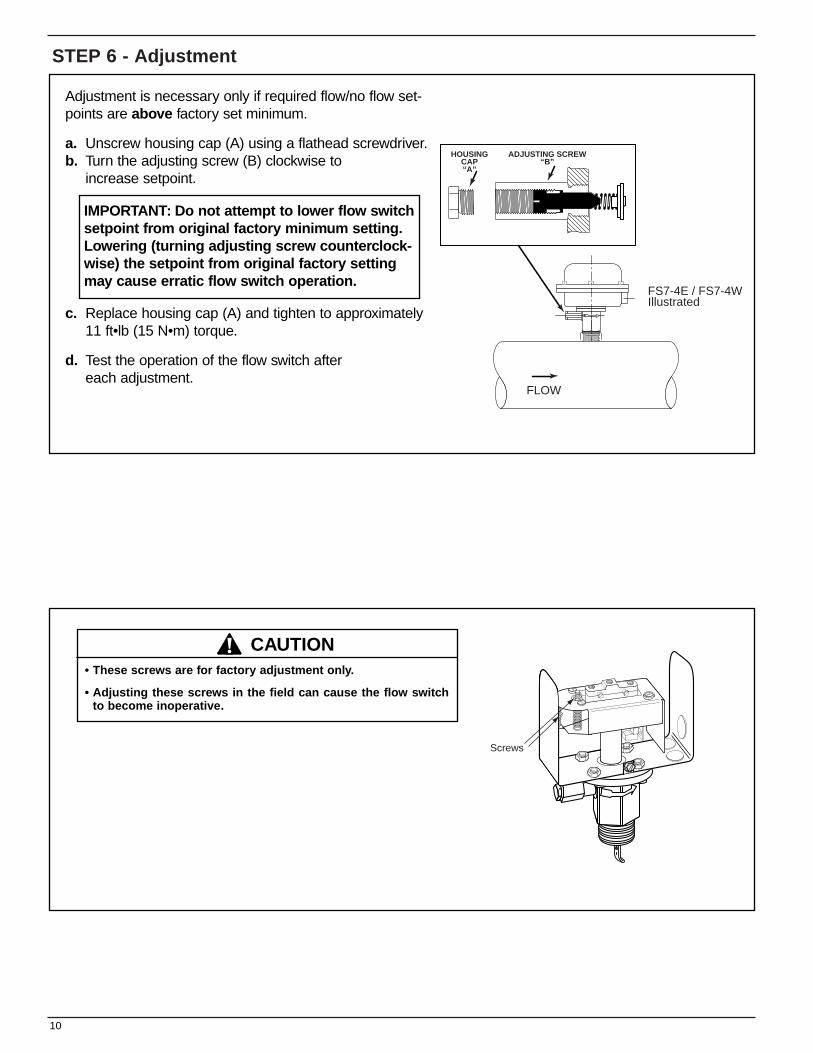
STEP 6 - Adjustment
HOUSINGCAP“A”
ADJUSTING SCREW“B”
FLOW
FS7-4E / FS7-4WIllustrated
Adjustment is necessary only if required flow/no flow set-points are above factory set minimum.
a. Unscrew housing cap (A) using a flathead screwdriver.b. Turn the adjusting screw (B) clockwise to
increase setpoint.
c. Replace housing cap (A) and tighten to approximately 11 ft•lb (15 N•m) torque.
d. Test the operation of the flow switch after each adjustment.
Screws
10
• These screws are for factory adjustment only.
• Adjusting these screws in the field can cause the flow switch to become inoperative.
! CAUTION
IMPORTANT: Do not attempt to lower flow switchsetpoint from original factory minimum setting.Lowering (turning adjusting screw counterclock-wise) the setpoint from original factory settingmay cause erratic flow switch operation.
11
MAINTENANCE
SCHEDULE:• Inspect paddles annually.Turbulent or high
flow velocity conditions may require more frequent inspection and/or replacement.
• Replace paddles if damaged or showing signs of wear.
• Replace flow switch every 5 years or 100,000 cycles, whichever occurs first.
TROUBLESHOOTING
Problem:
1. Flow Switch Does Not OperateSolution:a. Make sure power has been turned on to device
and flow switch.b. Verify that flow rate is high enough for flow switch
to activate. Measure flow rate and match with velocities shown in flow rate chart.
c. Check to see if paddle moves freely. Some system piping disassembly may be required.
2. Flow Switch Operates ErraticallySolution:a. Flow switch may be located in an area of high
turbulence causing paddles to flutter.b. Adjustment screw may have been turned below
original factory setpoint.Verify that flow rate is high enough for flow switch to activate. Measure flow rate and match with velocities shown in flow rate chart.
c. Check to see if paddle moves freely. Some system piping disassembly may be required.
3. Flow Switch Does Not DeactivateSolution:a. Check to see if paddle moves freely. Some system
piping disassembly may be required.b. Measure flow rate and match with velocities shown
in flow rate chart. Flow switch must prove flow before it can indicate no flow.

3500 N. Spaulding AvenueChicago, Illinois 60618tel: 773 267-1600fax: 773 267-0991www.mcdonnellmiller.com
©2001 ITT Industries Inc.Printed in U.S.A. 6-01 246618
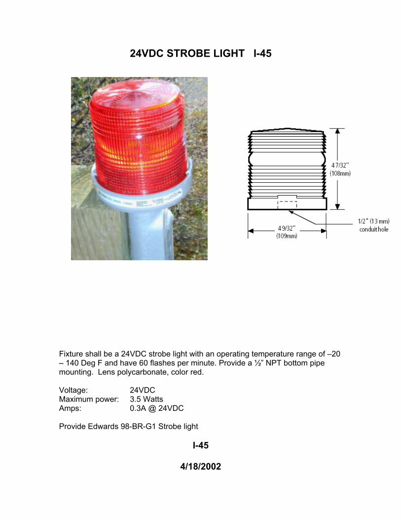
24VDC STROBE LIGHT I-45
Fixture shall be a 24VDC strobe light with an operating temperature range of –20 – 140 Deg F and have 60 flashes per minute. Provide a ½” NPT bottom pipe mounting. Lens polycarbonate, color red. Voltage: 24VDC Maximum power: 3.5 Watts Amps: 0.3A @ 24VDC Provide Edwards 98-BR-G1 Strobe light
I-45
4/18/2002
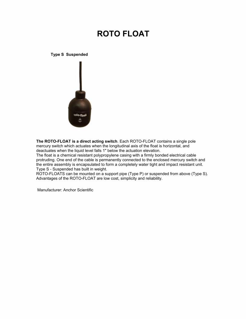
ROTO FLOAT
Type S Suspended
The ROTO-FLOAT is a direct acting switch. Each ROTO-FLOAT contains a single pole mercury switch which actuates when the longitudinal axis of the float is horizontal, and deactuates when the liquid level falls 1" below the actuation elevation. The float is a chemical resistant polypropylene casing with a firmly bonded electrical cable protruding. One end of the cable is permanently connected to the enclosed mercury switch and the entire assembly is encapsulated to form a completely water tight and impact resistant unit. Type S - Suspended has built in weight. ROTO-FLOATS can be mounted on a support pipe (Type P) or suspended from above (Type S). Advantages of the ROTO-FLOAT are low cost, simplicity and reliability. Manufacturer: Anchor Scientific