Embed Size (px)
Citation preview

Page 1 O f -4s, EDT 619107'"
E '3 ENGINEERING DATA TRANSMITTAL . 3 7
2. To: (Receiv ing Organizat ion)
D i s t r i b u t i o n
241-SY- lO l /Mi t iga t ion 5. Proj . IProg./Dept. /Div. :
3. From: ( O r i g i n a t i n g Organizat ion)
C h a r a t e r i z a t i o n Equipment
TR Benegas lLI0724) 6. Design A u t h o r i t y / Design AgentICog.
Engr.:
IAI IC) Item NO NO
18) DocumentlDrawlng No Sheet
- 1
IEl Title or Description of Data ID1
Rev Transmitted NO
WHC-SD-WM-TI-758 T Approval Designator IF1 Reason for Transmittal IG)
E, S. a. D or NIA 1 Approval 4 Review lsee WHC-CM~3~5. 2 Release 5 Post-Review Sec 12 71 3 Information 6. Dist. (Receipt Acknow Required)
Envi roment Q u a l i f i c a t i o n o f Power Cable f o r t h e Hydrogen M i t i g a t i o n Pump #3
Dispos$tion IHi & 111 1 Approved 4 Reviewed nolcamment 2 Approved wlcamment 5 Reviewed wlcamment 3 Disapproved wlcornment 6 Receipt acknowledged
4. Related EDT No.:
N/A
N/A
N/A
7. Purchase Order No.:
9. Equip./Component No.:
10. System/Bldg./Faci l i ty :
241-SY-101 12. Major Assm. Dwg. No.:
N/A
N/A 13. Permit /Permit A p p l i c a t i o n No.:
1 4 . Required Response Date:
Approval Reason Orlgl- Receiv-
nator Trana~ Dispo- Dispo- mittal sition sition
[See Approval Designator for required signatures)
BO-7400-172-2 (05/96) GEF097
BD3-7400-172-1

9 WHC-SD-WM-TI-758, Rev. 0
Environment Qualification of Power Cable for the Hydrogen Mitigation Pump #3
T . R . Benegas SESC, Richland, WA 99352 U.S. Department o f Energy Cont rac t DE-AC06-87RL10930
EDT/ECN: 619107 uc: 2000 Org Code: 75250 Charge Code: C10724 B&R Code: EW3120072 T o t a l Pages: -402- 103
Key Words: M i t i g a t i o n , Pump #3, Cables, HMR #3, 241-SY-101, Qual i f i c a t i o n
A b s t r a c t : T h i s r e p o r t p resents t h e severe environment q u a l i f i c a t i o n o f t h e power c a b l e i n severe r a d i a t i o n and thermal c o n d i t i o n s . T h i s q u a l i f i c a t i o n program prov ides F l o u r Dan ie l Hanford Company i n f o r m a t i o n f o r t h e use o f t h e new cab le in t h e mixer pump f o r hydrogen m i t i g a t i o n and r e t r i e v a l purposes.
P
TRADEMARK DISCLAIMER. Reference he re in t o any s p e c i f i c comnercial product, process, or se rv i ce by t r ade name, trademark, manufacturer, or otherwise, does not necessari Ly c o n s t i t u t e or imply i t s endorsement, recornendation, or f avo r ing by the Uni ted States Government or any agency thereof or i t s con t rac to rs o r subcontractors.
P r i n t e d i n the Un i ted States o f America. TO ob ta in copies o f t h i s document, contact : W H C D C S Document Contro l Services, P.O. Box 1970, Ma i l s top H6-08, Rich land WA 99352, Phone (509) 372-2420; Fax (509) 376-4989.
Approved for Public Release
A-6400-073 (10/95) GEF321
WHC-SD-WM-TI-758 , Rev. 0
Environment Qualification of Power Cable for the Hydrogen Mitigation Pump #3
Thermal and Radiation Environment
June 21, 1996
Prepared for:
WESTINGHOUSE HANFORD COMPANY P. 0. Box 1970 Richland, Washington 99352
Prepared by:
SCIENCE APPLICATIONS INTERNATIONAL CORPORATION 3250 Port of Benton Boulevard Richland, Washington 99352

WHC-SD-WM-TI-758, Rev. 0
Table of Contents
1 .O INTRODUCTION . . . . . . . . . . . . . . . . . 1
2.0 EQUIPMENT . . . . . . . . . . . . . . . . . . . . . . . . . . . . . . . . . . . . . . . . . . . . . . . . . 3
3.0 SEVERE ENVIRONMENT CONDITIONS . . . . . . . . . . . . . . . . . . . . . . . . . , , . 5 3.1 Thermal . . . . . . . . . . . . . . . . . . . . . . . . . . . . . . . . . . . . . . . . . . . . . . . . 5 3.2 Radiation . . . . . . , . . . . . . . . . . . . . . . . . . . . . . . . . . . . . . . . . . . . . , , , 5
4.0 QUALIFIED LIFE TESTING . . . . . . . . . . . . . . . . . . . . . . . . . . . . . . . . . . . . . . 7 . . . . . . . 7 . . . . . . . 7
4.1 Thermal and Radiation Testing . . . . . , . . . . . . . . . . . . . 4.2 Thermal and Radiation Test Results . . . . . . . . . . . . . . .
5.0 SUMMARY . . . . . . . . . . . . . . . . . . . . . . . . . . . . . . . . . . . . .
6.0 REFERENCES . . . . . . . . . . . . . . . . . . . . . . . . . . . .
. . . . 8
9
APPENDIX A - Radix Wire Company Power Cable Specifications APPENDIX B - Environmental Qualification Test Procedure for Cable Samples APPENDIX C - National Testing Systems, Inc.
Environmental Qualification Test Report for Cable Samples
11

WHC-SD-WM-TI-758 , Rev. 0
List of Tables
Table 1. Dose and Dose Rate Baseline . . . . . . . . . . . . . . . . . . . . . . . . . . . . . . . . . . . 6
... 111

WHC-SD-WM-TI-758, Rev. 0
1.0 INTRODUCTION
The Hydrogen Mitigation Test Pump (Mixer Pump) was installed in Tank 241-SY-101 of the Hanford underground storage tanks in July 1993. The pump mixes two distinct layers of waste in the tank: a fluid upper layer and a thick slurry lower layer. Mixing of these waste layers is performed to gradually release radiochemically produced hydrogen and prevent the tank's periodic "burps". A modified version of the Hydrogen Mitigation Test Pump (Mixer Pump) can also be used in the retrieval mode where it will be used to remove fluid waste from the tank.
The Mixer Pump service environment in the waste tanks presents severe radiation, chemical and thermal conditions.
A severe environment qualification of the hydrogen mitigation test pump (Hydrogen Mitigation Test Pump #1) was performed and reported in Reference 1. Hydrogen Mitigation Test Pump #1 is presently installed in Waste Tank 241-SY-101. Hydrogen Mitigation Pump $2. presently in storage, is a backup to Hydrogen Mitigation Pump #1.
Hydrogen Mitigation Pump #3 is presently undergoing engineering design and fabrication. Hydrogen Mitigation Pump #3 is identical in design and fabrication to Hydrogen Mitigation Pump #1, except for the capability to change the motor oil in Hydrogen Mitigation Pump #3. Hydrogen Mitigation Pump #3 has the same mitigation capability of the Hydrogen Mitigation Pump #1 and can also perform in a retrieval mode. For this reason the motoripump of Hydrogen Mitigation Pump #3 is mounted lower in a tank necessitating a longer support column, and power and instrument cables. Hydrogen Mitigation Pump #3 also uses a different power cable for the motor. This new cable must be qualified to operate in the severe thermal and radiation environment.
As with the Hydrogen Mitigation Test Pump #1 severe environment qualification program, the qualification of the power cable for Hydrogen Mitigation Pump #3 has been performed using Nuclear Regulatory Commission (NRC) and Institute of Electronic and Electrical Engineers (IEEE) guidance developed for qualifying equipment for nuclear power plants. The basis for this guidance consists of four documents:
1

WHC-SD-WM-TI-758, Rev. 0
NRC lOCFR 50.49 Environmental Qualification of Electric Equipment Important to Safety for Nuclear Power Plants
NRC Regulatory Guide 1.89 (Revision 1) June 1984 Environmental Qualification of Certain Electric Equipment Important to Safety for Nuclear Power Plants
IEEE Standard 323 - 1974 and 1983 Qualifiing Class 1E Equipment for Nuclear Power Generating Stations
IEEE Standard 383 - 1974 Type Test of Class 1E Electric Cables; Field Splicers and Connections for Nuclear Power Generating Stations.
The qualification program uses an "analysis methodology which is defined in IEEE Std 323 as:
"Logical assessment or valid mathematical model of equipment to be qualified. Qualification consists of quantitative analysis supported by test data. operating experience or physical laws of nature to demonstrate that equipment can perform under severe conditions."
This report presents the severe environment qualification of the power cable in severe radiation and thermal conditions. This qualification program provides Westinghouse Hanford Company information for the use of the new cable in the mixer pump for hydrogen mitigation and retrieval purposes.
2

WHC-SD-WM-TI-758, Rev. 0
2.0 EQUIPMENT
The Mixer Pumps consist of four equipment subsystems: the motor/pump. the mechanical structure, instrumentation packages, and the control system.
A review of the mixer pumps’ equipment interaction with the severe radiation. thermal, and chemical environment yielded the following information:
Motor/Pump
In the motor/pump subsystem, the only components sensitive to the severe environment are the power cable, motor, oil and seals. The pump indexing equipment is located in the pump pit outside the severe environment.
Mechanical Structure
The mechanical structure is made of carbon and stainless steel. These materials are not affected by the radiation environment; however, they are susceptibility to chemical/thermal environments.
Instrumentation Packages
The operating instrumentation packages on the SY-IO1 Mixer Pump are temperature, pressure, moisture, vibration and strain sensors. Parameters monitored include discharge leg pressure, temperature, and flow; pump discharge plenum pressure; motor vibration, oil temperature, and moisture; mixer pump column bending. Some of these instruments are located in the severe environment and are susceptible to its effects; however, the failure of these components will not affect the pump’s ability to operate satisfactorily.
Control System
The Control System is located outside the tank and is not affected by the severe environment.

WHC-SD-WM-TI-758 , Rev. 0
The power cable used in the Hydrogen Mitigation Pump #3 was supplied by Radix Wire Company. The power cable specifications, requested by Westinghouse Hanford Company, were as follows:
Silicone rubber motor lead with K-fiber braid Type SRML-K, copper wire, Class H stranding (350 kcmil-427 strands), 600 V, 125°C minimum, UL Style 3410, Nuclear Radiation Resistance rated excellent, nominal O.D. 350 kcmil-1.06" maximum.
This cable is described by Radix Wire Company in Appendix A. Radix Wire Company Cable SRML-K is identical to SRK cable. The quality assurance element of this program established the equivalence for the two nomenclatures of the power cable.
4

WHC-SD-WM-TI-758, Rev. 0
3.0 SEVERE ENVIRONMENT CONDITIONS
The power cable operates in thermal and radiation environments associated with the Hanford underground storage tanks as well as the stress associated with the pump's operation. In order to establish the service conditions for the power cable, the severe environments of Waste Tank 241-SY-101 (SY-101) were used as the baseline. The replacement pump will be installed in Tank SY-101 and will operated until removed or failure. The pump will be operated on a schedule consistent with tank safety considerations. The pump is assumed to operate in its "mixer mode" of three times per week, for 25 minutes each time. In addition, the pump will operate in a "retrieval mode" 24 hours per day for 4 weeks. Both the "mixer" and "retrieval" mode are included in this qualification testing. This operating scenario converts to a non-operating state of 97% and a mixer and retrieval operating state of 3%. These percentages are of the time the pump is continuously in-place in the waste tank. This Hydrogen Mitigation Pump #3 mixer pump is assumed to be installed on January 1, 1997.
3.1 Thermal
The SY-101 ambient waste temperature has been established at 118°F (SAIC 1995). This is the thermal environment of the pump under non-ooeratine, conditions. Engineering analysis on Hydrogen Mitigation Pump # 3 , with the specified Radix cable, has established the cable temperature to be 257'F during pump operation (Merriman 1995).
3.2 Radiation
The radiation environment of the waste tank has been established using tank radiological sampling measurements. The details are presented by SAIC (1995). Allowances must be made for shielding of the cable by the exterior mechanical structure of the mixer pump. SAIC (1995) established a shielding factor of 2.9 between the dose rate and dose outside the pump and the exposure of the cable. In Table 1, the dose rate and integrated dose in the waste tank are estimated. This table also estimates the cable's integrated dose, including the shielding provided by the mixer pump's mechanical structure,
5

WHC-SD-WM-TI-758, Rev, 0
Table 1. Dose and Dose Rate Baseline
* Dose rate and integrated dose are internal to waste tank, but external to pump.
For these estimates of radiation dose, the mixer pump is assumed to be installed in the waste tank on January 1, 1997.
6
WHC-SD-WM-TI-758, Rev. 0
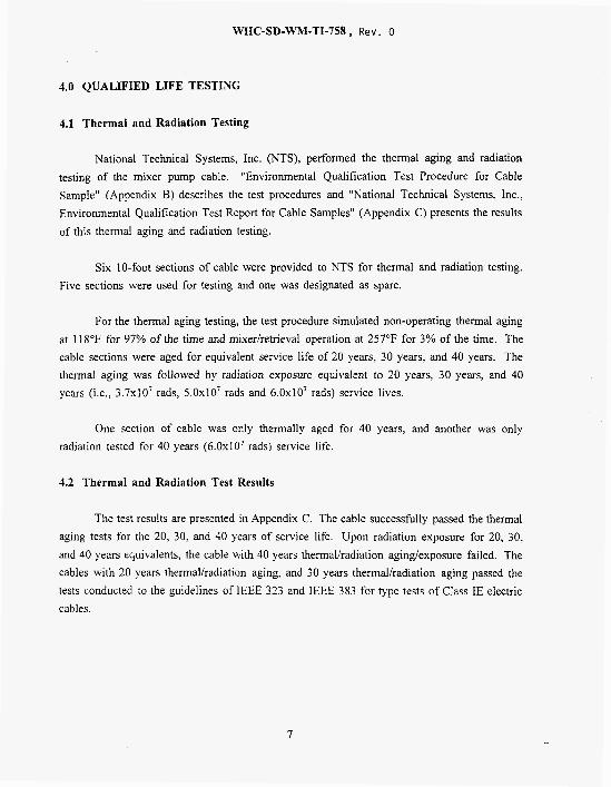
4.0 QUALIFIED LIFE TESTING
4.1 Thermal and Radiation Testing
National Technical Systems, Inc. (NTS), performed the thermal aging and radiation testing of the mixer pump cable. "Environmental Qualification Test Procedure for Cable Sample" (Appendix B) describes the test procedures and "National Technical Systems, Inc., Environmental Qualification Test Report for Cable Samples" (Appendix C) presents the results of this thermal aging and radiation testing.
Six IO-foot sections of cable were provided to NTS for thermal and radiation testing. Five sections were used for testing and one was designated as spare.
For the thermal aging testing, the test procedure simulated non-operating thermal aging at 118°F for 97% of the time and mixer/retrieval operation at 257°F for 3% of the time. The cable sections were aged for equivalent service life of 20 years, 30 years, and 40 years. The thermal aging was followed by radiation exposure equivalent to 20 years, 30 years, and 40 years ( i t . , 3.7~10' rads, 5 . 0 ~ 1 0 ~ rads and 6 . 0 ~ 1 0 ~ rads) service lives.
One section of cable was only thermally aged for 40 years, and another was only radiation tested for 40 years (6.0~10' rads) service life.
4.2 Thermal and Radiation Test Results
The test results are presented in Appendix C. The cable successfully passed the thermal aging tests for the 20, 30, and 40 years of service life. Upon radiation exposure for 20, 30, and 40 years equivalents, the cable with 40 years thermalhadiation agingkxposure failed. The cables with 20 years thermalhadiation aging, and 30 years thermauradiation aging passed the tests conducted to the guidelines of IEEE 323 and IEEE 383 for type tests of Class IE electric cables.
7

WHC-SD-WM-TI-758 , Rev. 0
5.0 SUMMARY
The power cable being used in Hydrogen Mitigation Pump #3 has undergone thermal aging and radiation qualification testing. This cable manufactured by Radix Wire Company is a silicone rubber motor lead cable.
The baseline thermal and radiation environments used for the qualification testing are equivalent to the severe environments of waste Tank 241-SY-101 of the Hanford underground storage tanks. It is assumed the Hydrogen Mixer Pump #3 is installed in the waste tank on January 1, 1997 and is non-operational 97% of the time and operational 3% of the time. The operation includes both mixing and retrieval.
The cable passed thermal aging qualification testing equivalent to 20, 30, and 40 year service life. Upon further exposure to 20, 30, and 40 year equivalent radiation environments, the cable exposed to the combined 20 and 30 year thermalhadiation environments passed the tests and are considered qualified to operate in these environments. The cable exposed to the combined 40 year thermalhadiation environments failed the tests and are not qualified to operate in this environment.
The cables exposed only to the 40 year thermal and 40 year radiation environments also passed the qualification tests.
8

\I'HC-SD-WM-TI-758, Rev. 0
6.0 REFERENCES
1. Science Applications International Corporation, 1995, Severe Environments Qualification of SY-IO1 Hydrogen Mitigation Test Pump, WHC-SD-WM-IT-727.
2. R. E. Merriman, 1995, Design Analysis HMT # % I , WHC-Mitigation Equipment Engineering, September 21, 1995.
9

WHC-SD-WM-TI-758, Rev. 0
APPENDIX A
Radix Wire Company Power Cable Specifications


3 ‘L, r , .- , MOTOR LEAD & APPARAIII; / / IF E WHC-SD-WM-TI-758, Rev. o -.- ___-._
600 volt 200‘C, Specifitotion RW-20002 Ut STYLE 3410
Port Number
Size AWG/ MCM
KGG 1 AT007 KGG 1 2T007 KGG 1 OT007 KGG08T054 KGG06T084 KGGOATI 33 KGG02T259 KGGOlT259 KGGX 1 T259 KGGX2T259 KGGX3T259 KGGXAT259 KGG25T427 KGG35T427 KGG50T427
14 12 10
1 /o 2/0 3 /O 4 /O 250 350 500
Strands/ Shand
Diameter
7/0242 7/0305 7/0385 54/0177 84/0177 133/0 177
259/0286 427/0242 427/02 8 6 427/0342
Conductor Diometer
(In1
Insulation Broid Thickness Thickness
(In1 (In1
Nominal Diometer
(In1
0.072 0.088 0.1 15 0.1 A2 0.2 10 0.262 0.330 0.365 0.415 0.465 0.5 1 A 0.590 0.655 0.775 0.923
0.045 0.035 0.045 0.035 0.045 0.040 0.060 0.040 0.060 0.040 0.060 0.040 0.060 0.040 0.080 0.040 0.080 0.040 0.080 0040 0.080 0:04O 0.000 0.040 0.095 0.040 0.095 0.040 0.095 0.040
0.236 0.252 0.289 0.348 0.420 0.476 0.544 0.615 0.665 0.715 0.764 0.840 0.939 1.059 1.213
Approxlmaie Weight
Ilbr/Mh)
33.4 43.9 60.7 94.2
137.2 193.2 280.1 359.9 444.6 534 A 656.9 81 1.4 976.6
1327.1 1847.4
RADIX WIRE COMPANY 26260 Lakeland Blvd. Cleveland, OH 44132 216/731-9191 A-3 RDll107 W112 547
L..”. . I ‘ !
\WC-SD-Wh.I-TI-758: Rev. 0
APPENDIX B
Environmental Qualification Test Procedure for Cable Samples

c. \WC-SD-\Vh.I-TI-758. Rev. 0
Tat-No. 50776-9TN RaLrIon 0
Eh7?RoNMENTAL QUALIFICATION rpsT PROCEDURE FOB
CABLESAMPLES
FOR
00 'd 1126 L P L 902 'ON X'YA 6-2
MN/3 I US

WHC-SD-WM-TI-75S, Rev. 0
Test Procedure No. 60776-97N Revision 0
ENVIRONMENTAL QUALIFICATION TEST PROCEDURE FOR
CABLE SAMPLES
FOR
SCIENCE APPLICATIONS INTERNATIONAL CORPORATION 3250 PORT OF BEhTON BOULEVARD
RICHLAND, WA 99352
Purchase Order Number: 13-970050-90
Prepared by: Date: 0?2@k74 Charles R. Pilotte, Project Engineer, Nuclear Services NTS/Northeast
Reviewed and Approved by: GzLL///LA Date: / B /h P O
Independent ReviewedNuhear Services NTSlNortheast
? - r Date: 7 tl T Y b ?k
Reviewed and Approved by: Date:
SAIC Representative
CRP/sm116077697. SA1
Y3 -3

\i;HC-SD-Wh.I-TI-758, Rev. 0
TABLE OF CONTENTS
SECTION
1.0 SCOPE
2.0 APPLICABLE REFERENCE DOCUMENTS
3.0 COMPONENT DESCRIPTION
4.0 PROGRAM SEQUENCE
5.0 INCOMING INSPECTION/BASELINE FUNCTIONAL TESTING
6.0 THERMALAGING
7.0 IRRADIATION
8.0 TESTEQUIPMENT
9.0 FINAL DOCUMENTATION
APPENDIX A: SAMPLE TEST DATA SHEETS
PAGE NOS
1-1
2-1
3-1
4-1
5-1 to 5-2
6-1 to 6-4
7-1 to 7-3
8-1
9-1
A-1 to A-4
Procedure No. 60776-97N Revision 0

WHC-SD-WM-TI-758. Rev. 0
1.0 SCOPE
The purpose of this qualification test procedure is to present the general requirements and
methodology which shall be utilized to qualify the SAIC test items identified within Section 3.0
to the environmental conditions anticipated for its intended installation. The intent of the test
program is to qualify the test items to encompass the aging requirements contained within SAIC
Purchase. order No. 13-970050-90. The test program is intended to meet the guidelines of IEEE
323-1983@90) and IEEE 383-1974@92) for type tests of Class 1E electric cables.
Specifically, this test procedure details the type testing techniques that will be utilized to
provide SAIC with the environmental qualification data stipulated within SAIC Purchase Order
13-970050-90, dated 13 February 1996.
The qualification testing program outlined within this document shall be conducted in
accordance with the NTS/Northeast Quality Manual, Revision 3, dated July 14, 1992. This
insures that the applicable provisions of lOCFR, Part 21 and Part 50, Appendix B are fulfilled.
Procedure No. 60776-97N Revision 0

WHC-SD-WM-TI-758, Rev. 0
E rn
2.0 y
2.1
2.2
2.3
2.4
2.5
2.6
2.7
2.8
2.9
IEEE Std. 323-1983@90), Qualifvine Class 1E Eauipment for Nuclear Power Generatine Stations.
IEEE 383-1974@92), $$ Sulices. and Connections for Nuclear Power Generatine Stations.
NTSlNortheast Quote Number 6-016-N5668.
Science Applications International Corporation, Purchase Order No. 13-970050-90, dated 13 February 1996.
NTS/Northeast Quality Manual, Revision 3, dated July 14, 1992.
Code of Federal Regulations, Title 10, Part 21, Reportine of Defects and Noncomulianct
Code of Federal Regulations, Title 10, Part 50, Appendix B, Quality Assurance )
NTSlNortheast Audit Report No. NTSIA-93-030, dated May 12, 1993 of Isomedix, located in Whippany, NJ.
NTSlNortheast Report No. NTSICGS-93-027 dated May 17, 1993 of Springborn Laboratories, located in Enfield, CT.
8- 6
Procedure No. 60776-97N Revision 0

WHC-SD-WM-TI-758, Rev. 0
3.0 COMPO NENT DESCRIPTION
The following cable samples will be supplied by SAIC.
Sample Cables; Manufacturer: Radix Wire Co.; PIN SRML-K Radix; 1IC Silicone Rubber Insulation with K-Fiber jacket; 600 VAC, 200°C; UL Style 3410. Each sample 10 feet in length minimum. Distributor: Anixter
Sample cables 1, 2, & 3 shall undergo thermallradiation aging.
Sample cable 4 shall undergo thermal aging only.
Sample cable 5 shall undergo radiation aging only.
Sample cable 6 is a spare cable and will have activation energy determination performed on insulation jacket.
Procedure No. Revision 0 --
6-7

WHC-SD-WM-TI-758, Rev. 0
4.0 PROGRAMSEOUENC E
The environmental qualification shall be conducted in the following sequence:
1. Incoming Inspection
2. Baseline Functional Test
3. Thermal Aging
4. Post Thermal Aging Baseline Test
5. Irradiation
6. Post Irradiation Baseline Test
NOTE: The program sequence performed is per the request of SAIC.
Procedure No. 60776-97N Revision 0
6-8


\WC-SD-WhI-TI-758, Rev. 0
5.0 INCOMING INSPECTION/BASELWE IWNCTIONAL TESTING (conlhued)
5.2 Baseline Functional Testing (continued)
C. Dielectric Withstanding Voltage - While still immersed, a test of 2X rated voltage plus loo0 (2X 600 + IO00 = 2200 VAC) will be applied for five (5) minutes.
Acceutance Criteria
No leakage in excess of 5 mA shall occur.
l 3 - I O
Procedure No. W776-97N Revision 0

WHC-SD-WM-TI-758, Rev. 0
6.0 THERMALAGING
The following data shall be used to determine the accelerated aging times to provide a
20 year qualified service life for sample 1, 30 year qualified life for sample 2 and a 40
year qualified life for samples 3 and 4.
6.1 Activation Enemv (ev)
The weak-link age sensitive material of the subject cables is the silicone-rubber
insulation.
The activation energy value for this material has not been provided by SAIC or
the manufacturer of the material.
determination of activation energy.
Laboratories located in Enfield, CT for Therm0 Gravimetric Analysis. (TGA).
NTWNortheast shall utilize sample cable 6 for
Insulation samples shall be sent to Springborn
Springborn Laboratories is an approved commercial grade vendor of
NTS/Northeast. NTS/Northeast shall maintain under their QA program all records
pertaining to Springbom Laboratories to assure compliance with lOCFR, Part 21 and Part
50, Appendix B.
Historical data shows that for cured silicone rubber typical activation energy values fall
within the range of 1.5 to 2.5 ev. NTS/Northeast shall conservatively choose a value of
1.0 ev for this program. Actual values determined by Springborn Laboratories will be
included within the final test report.
Aging times based on activation energy value of 1.0 ev will be utilized unless
actual results from TGA analysis are lower, in which case, calculations will be adjusted.
Actual anticipated values from analysis at this time are expected to exceed 1.5 ev.
Procedure No. 60776-97N Revision 0

WHC-SD-WM-TI-758, Rev. 0
Non-operating
Mixer/Retrieval Operation
6.0 THERMA L AGING (continued)
118°F 97% of time
257°F 3% of time
6.2 Service Conditions
[20 years (365 days/yr) + 5 leap year days] [24 hrslday (1.1)(.03)] = 5,786 hours
[30 years (365 dayslyr) + 7 leap year days] [24 hrs/day (1.1)(.03)] = 8,678 hours
[40 years (365 dayslyr) + 10 leap year days] [!24 hrslday (1.1)(.03)] = 11,571 hours
6.3 Acing Duration
Using the Arrhenius Equation, the thermal aging time required to produce the
applicable qualified service life for the subject cables plus 10% margin at the service temperature
conditions given, can be calculated as follows:
Procedure No. 60776-97N Revision 0
B - ) a

WHC-SD-WM-TI-758, Rev. 0
Service Life
20 years
30 vears
6.0 L ING(continued)
118°F 257°F Total Hours
6.62 hours 223.40 hours 230 hours
9.93 hours 335.05 hours 345 hours
6.3 Aping Duration (continued)
where:
f = Thermal A '
t, = Service Lizmg 257°F (125"Cl 118°F (48°C)
20 years 187,066 hours 5,786 hours 30 years 280,587 hours 8,678 hours 40 years 374,133 hours 11,571 hours
TI = Service Temperature (OK) (118°F = 321°K and 257°F = 398°K) T2 = Thermal A ing Temperature (OK) 448°K 6 = Activation lfnergy (1.0 eV) K = Boltzrnann's Constant = .8617 x lo4 eV/"K
The following table results in the calculated values for a 20, 30 and 40 year
qualified service life using an aging temperature of 175°C (448°K) for T,.
I 40 years 1 13.25 hours I 446.70 hours I 460 hours I Total hours tabulated have been rounded-off to nearest hours. The four (4) cables
therefore shall be aged at 175°C as follows:
Sample 1 Sample 2 Samples 3 & 4
230 Hrs = 20 Yrs + 10% Margin 345 Hrs = 30 Yrs + 10% Margin 460 Hrs = 40 Yrs + 10% Margin
During thermal aging the four (4) cables shall be mounted on mandrels. Thermal
aging will be conducted within a forced hot-air temperature chamber. The aging oven
temperature conditions will be continuously monitored and recorded. The test items will
remain de-energid during aging.
Procedure No. 60776-97N Revision 0
WHC-SD-WM-TI-758, Rev. 0
6.0 THERMAL AGING (continued)
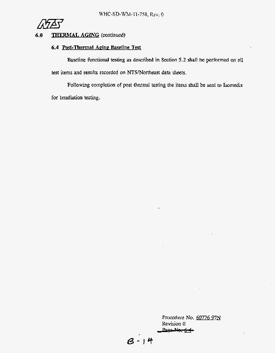
6.4 Post-Thermal Acing Baseline TE&
Baseline functional testing as described in Section 5.2 shall be performed on all
test items and results recorded on NTSlNortheast data sheets.
Following completion of post thermal testing the items shall be sent to Isomedix
for Irradiation testing.
Procedure No. 60776-97N Revision 0
8 - t c t

WKC-SD-WM-TI-758, Rev. 0
7.0 IRRADIATION
The samples listed below mounted on mandrels of approximately 20 times the O.D. of
the cable shall be carefully packaged and sent to Isomedix Inc., located in Whippany, NI for
irradiation exposure.
Isomedix is an approved vendor of NTSlNortheast and complies to the applicable
requirements of 10 CFR, Part 21 and Part 50, Appendix B. An audit was performed on
Isomedix which resulted with Isomedix being added to NTSlNortheast Approved Vendor listing
under NTS/Northeast Audit Report No. NTSlA-93-030.
Four samples as identified shall undergo irradiation testing. The Total Integrated Dose
shall be as follows for each sample.
Sample 1 20 Yrs Sample 2 30 Yrs Sample 3 40 Yrs Sample 5
3.7 x lo7 Rads 5 x lo7 Rads 6 x lo7 Rads 6 x lo7 Rads
The samples shall be oriented such that the irradiation source is uniformly dispersed.
The samples shall be exposed to a Cobalt -60 gamma field, at a dose rate of between 5x1@ rads
per hour and 1 x 10⁶ rads per hour.
Halfway through the irradiation exposure the test samples shall be rotated 180"(if
required) to provide even distribution of gamma doses throughout the test samples.
Dosimetry will be performed using Hanvell 4034 Red Perspex dosimeters, utilizing a
Bausch and Lomb Model 1001 spectrophotometer as the readout instrument,or equivalent. This
system is traceable to the National Institute of Standards and Technology (NIST). This system
has a total uncertainty of f 8% error.
Procedure No. 60776-97N Revision 0
d - ) 5

WHC-SD-WM-TI-758, Rev. 0
7.0 IRRADIATION (continued)
Upon completion of testing, Isomedix shall carefully package the test samples and return
them to NTS/Northeast. The cables shall remain mounted on the mandrels to minimize any
damaging of the cables from handling.
Isomedix shall issue documentation identifying the samples tested, Total Integrated Dose
received and equipment utilized with certification to NIST. All documentation shall be certified
by an authorized Quality Assurance representative of Isomedix. The documentation issued shall
be made an attachment to the final report issued by NTWNortheast to SAIC.
7.1 Post Irradiation Baseline Test
Following the Irradiation exposure and return to NTS/Northeast the samples shall
be visually inspected for any signs of damage or deterioration. The results observed
shall be documented on a NTS/Northeast test data sheet.
Following this the baseline functional testing described in Section 5.2 of this
procedure shall be repeated, having the same acceptance criteria.
7.1.1
After completion of the baseline testing per Section 5.2, the following
additional testing shall be performed.
A) While still immersed a Dielectric Voltage test shall be performed with a test potential of 80 VAC/mil thickness of insulation. The test potential of shall be applied for a duration of five (5) minutes. Actual mil thickness of the insulation jacket shall be measured and recorded by NTSINortheast.
Upon completion of step A, the cables shall be removed from the bath and allowed to dry for 24 hours. Next, the cables shall be removed from the mandrels and straightened. Following this, the cable shall be reversed wraped around the mandrels.
B)
Procedure No. 60776-97N Revision 0
6- ) b

7.0 IRRADIATION (continued)
7.1 Post Irradiation Baseline Test (continued)
7.1.1 (continued)
C) The cables shall be submerged in the water bath and allowed to soak for a period of 1 hour.
A test potential of 80 VAC/mil thickness of insulation shall be applied again for a period of five (5 ) minutes.
D)
Acce~tance Criteria
Leakage current shall not exceed 5 maAc.
Note: The acceptance value of 5 maAc is the limits of NTSNortheast test equipment. If leakage values of 5 maAc are achieved, NTSlNortheast will document the maximum voltage achieved. Results of steps A through D are for informational purposes only.
Procedure No. 60776-97N Revision 0
6-,7

WHC-SD-WM-TI-758, Rev. 0
All test equipment used for this program shall be checked prior to testing to assure that
it is in calibration and that the parameters being measured are appropriate for the range on the
measuring instrument.
Calibration is performed and checked on a routine basis using standards traceable to the
National Institute of Standards and Technology (NIST). Calibration of equipment is performed
in accordance with the NTS quality program.
A list of test equipment used and verification of the suitability of the measuring
instrument shall be included in the final report and will document the type of equipment,
accuracies, and calibration due date as a minimum.
Procedure No. 60776-97N Revision 0
6- /B

WHC-SD-WM-TI-758, Rev. 0
9.0 FINAL DOCUMENTATION
Upon completion of the environmental qualification testing, NTSINortheast will submit
a single test report to SAIC. This report will include, but not be limited to, the following:
1.
2.
3.
4. Thermal aging temperature recording.
5.
A detailed description of the test items with photographs for identification.
Results of all functional tests, including methods and equipment used.
A detailed description of the test setups used including photographs.
A list of all test equipment used, the last date of calibration and frequency of calibration. (Note: All equipment is calibrated with traceability to the National Institute- of Standards and Technology (NIST). The detailed records are available for review and audit at NTSINortheast).
If applicable, anomalous results and failure to meet acceptance criteria will be noted in
the test report.
Procedure No. 60776-97N Revision 0

WHC-SD-WM-TI-758, Rev. 0
APPENDIX A: TEST DATA SHEETS
Procedure No. 60776-97N Revision 0
6- ao

Job Number 60776-97N
Customer SAIC
Cable Test Sample
Test Baseline
Purchase Order No. 13-910050-90
Test Engineer: Form 20 Z
Date I Wge of
Specification T.P. 60776-97N
ModelISerial No. SRML-K
Mode of Operation Insulation Resistance
Procedure No. 60776-97N Revision 0
n- ai

WHC-SD-WM-TI-758, Rev. 0
Job Number 60776-97N
CUStomS SAIC
Test Sample Cable
Test Baseline
purchase Order No. 13-970050-90
Date I Page of
Specification T.P. 60776-97N
ModdlSerial No. SRML-K
Mode of Operation Dielectnc Voltage
@ 2200 VAC
Procedure No. 60776-97N Revision 0
113- a7

60776-97N Job Number SAlC Customer ~
Test Sample Cable Test Post Thermal, Irradiation
purchase Order No. 13-970050-90
~~
Leakage current shall not exceed 5 maAc
NOTES: Samples 1, 2 and 3 are post thermal, irradiation.
Sample 4 is post thermal only
Sample 5 is post irradiation only
Inspector:
Test Engineer:
Date I Wge of Specification T.P. 60776-97N
ModellSerial No. SRML-K
Mode of Operation Dielectric Voltage
Procedure No. 60776-97N Revision 0
18- 23
Form 20.2

WHC-SD-WM-TI-758. Rev. 0
APPENDIX C
National Testing Systems, Inc. Environmental Qualification Test
Report for Cable Samples

WHC-SD-WM-TI-758, Rev. 0
TestReportNo. 6on6-9RJ Revision 0
ENVIRONMENTAL QUALIF’ICAnON TEST REPORT FOR
CABLE SAMPLES
FOR
SCIENCE APPLICATIONS INTERNATIONAL CORPORATION 3250 PORT OF BENTON BOULEVARD
13-970050-90 Purchase Order Number:
Prepared by: Date: -196 Charles R. Pilotte, Project Engineer, Nuclear Services NTS/Northeast
Date: zJI;A%t/c /WL Reviewed and Approved by:
Date: Reviewed and Approved by:
CRPlsd16077697.SAI

WHC-SD-WM-TI-758. Rev. 0
SECTION 1.0 SCOPE
2.0 APPLICABLE REFERENCE DOCUMENTS
3.0 COMPONENT DESCRIPnON
4.0 PROGRAM SEQUENCE
5.0 INCOMING INSPECTION/BASELINE FUNCTIONAL TESTING
6.0 THERMAL AGING
7.0 IRRADIATlON
8.0 CONCLUSIONS AND OBSERVATIONS
9.0 TEST EQUIPMENT LIST
APPENDIX A:
APPENDIX B:
NTS TEST DATA SHEETS
ANALYTICAL REPORT BY SPRINGBORN LABORATORIES
APPENDIX C:
APPENDIX D:
APPENDIX E
“HEMAL AGING CHARTS
ISOMEDIX REPORT
PHOTOGRAPHS
I5uxrxs 1-1
2-1
3-1
4-1
5-1 to 5-2
6 1 to 6-4
7-1 to 7-3
8-1 to 8-2
9-1 to 9-2
A-1 toA-4
B-1 to B-9
C-1 to C-23
D-1 to D-5
E-1 to E-3
Report No. @776-9 7 N Revision 0
t3- 7 6

WHC-SD-WM-TI-758, Rev. 0
1.0 SCOPE
The purppse of this qualification test report is to pnsent the general requirrments and
methodology which was utilized to qualify the SAIC test items identified within Section 3.0 to
the environmental conditions anticipated for its intended installation. The intent of the test
program was to qualify the test items to encompass the aging requirements contained within
SAIC Purchase order No. 13-970050-90. The test program was conducted to the guidelines of
JEEE 323-1983@90) and IEEE 383-1974@92) for type tests of Class 1E ektric cables.
Specifically, this test report details the type testing techniques that were utilized to
provide SAIC with the environmental qualification data stipulated within SAIC Purchase Order
13-970050-90, dated 13 February 1996 and the results of Uie testing activities.
The qualification testing program outlined within this report was conducted in accordance
with the NTS/Northeast Quality Manual, Revision 3, dated July 14, 1992. This insures that the
applicable provisions of lOCFR, Part 21 and Part 50, Appendix B are fulfilled.
Report No. m776-9m Revision 0

WHC-SD-WM-TI-758. Rev 0
2.0 b!umKA&REFERENCZF=-
2.1
2.2
2.3
2.4
2.5
2.6
2.7
2.8
2.9
2.10
EEE Std. 323-1983(R90), W
IEEE 383-1974@92), M i r n -
NTS/Northeast Quote Number 6-016-N5668.
Sacnce Applications International Corporation, purchase Order No. 13-970050-90, dated 13 F e b w 1996.
NTSMorthcast Quality Manual, Revision 3, dated July 14,1992.
Code of Federal Regulations, Title 10, Part 21, Of lXfStS and
Code of Federal Regulations, Title 10, Part 50, Appendix B, Power P w Fuel
NTSMortheast Audit Report No. NTS/A-93430, dated May 12, 1993 Of Isomcdix, located in W h i p p y , NJ.
NTSlNortheast Report No. NTSICGS-93-027 dated May 17,1993 of Springborn Laboratories, located in Enfield, CT.
NTSlNortheast Test Procedure No. 6077697N, Rev. 0, dated 1 March 1996.
Report No. So77697N Revision 0
B - a r

WHC-SD-WM-TI-758, Rev. 0
The following cable samples were supplied by SAIC.
ptr4 Sample Cables; Manufacturer: Radix Wire Co.; PIN SRML-K Radix; 1IC Silicone Rubber Insulation with K-Fiber jacket; 600 VAC, 200°C; UL Style 3410. Each sample 10 feet in length minimum. Distributor: Anixter
Sample cables 1, 2, & 3 underwent t h e d d i a t i o n aging.
Sample cable 4 underwent thcnnal aging only.
Sample cable 5 undenvmt radiation aging only.
Sample cable 6 w-as a spare cable and had activation energy determination performed on the insulation jacket.
~ e p o r t NO. ~ 7 7 6 - 9 7 ~ Revision 0

WHC-SD-WM-TI-758, Rev. 0
4.0 m z E m
The envimnmenal qualification was conducted in the following sequence:
1. I n c o m h g h p t i o n
2. Bascline Functional Test
3. Thmnal Aging
4.
5. Irradiation
6. Post Irradiation Baseline Test
Post Thermal Aging Baseline Tcst
NOTE: The program sequence performed was per the quest of SAIC.
Report No. fl7’76-97N Revision 0 -
t3- 30

WHC-SD-WM-TI-758, Rev. 0
5.1 Iefsmt ne I n m a t m
Upon receipt of the test samples at NTSINortheast, the test items described in
Section 3.0 of this document were visually inspected to ensure there has been no damage
due to shipping and handling and to confirm that the test item model numbers coincide
with those listed in the packing list. There was no evidence of damage and the items
w e n iogged in, tagged and proceeded to testing.
5.2 $ $ i n in
The cable sample numbers 1 through 5 with identification tags attached for
traceability were coiled around mandrels having a diameter of 18 inches. Each cable
sample was coiled around the mandrel so that the affected section of each cable under
test was approximately 10 feet. Each cable sample was then subjected to the following
tests. Appendix A of this report contains actual data sheets and values recorded.
A.
B.
Continuitv Test - Measure and record the continuity of each cable sample.
Ins ulation Resistance - Submerge the test samples in tap water at room temperature. After a one (1) hour soak, measure and record the insulation resistance between the conductor and ground. A test voltage of 500 VDC will be applied for one (1) minute prior to the insulation resistance measurement.
Insulation resistance values were 2 1.0 megohms for each sample.
Report No. §0776-9m Revision 0 -
&-3 I

WHC-SD-WM-TI-758, Rev. 0
5.0 D V C o m G ~ ~ p E ~ O N ~ * S E L ~ m K m r Y A L (continued)
5 3 Weline Fund ions1 Test iu (continued)
C. -Withstand inp V w - While still immersed, a test of 2X rated voltage plus loo0 (2X 600 + loo0 = 2200 VAC) was applied for five (5) minutes.
&s!&
No leakage in excess of 5 mAAC o c c u m d . Actual leakage average was
1.9 mAAC for initial baseline, 2.03 mAAC for post thermal and 2.05 mAAC for
post irradiation. For a test potential of 2200 VAC, 60 Hz, this results in an
impedance of 1.16 x lob ohms for initial baseline, 1.08 x 10⁶ ohms for post
thermal and 1.07 x 10⁶ ohms for post irradiation. Actual values recorded for
each cable are contained within Appendix A of this report.
Report No. 50776-97N Revision 0 -
6 - 3 8

WHC-SD-WM-TI-758, Rev. 0
6.0 Z E E J I M J l M
The following data was used to determine the accelerated aging times to provide a 20
year qualified senice life for sample 1, 30 year qualified life for sample 2 and a 40 year
qualified life for samples 3 and 4.
6.1 Act ivation Erie-
The weak-link age sensitive material of the subject cables is the silicone-rubbcr
insulation.
The activation energy value for this matuial had not been provided by SAIC or
the manufacturer of the material. NTsMorthcast utilized sample cable 6 for
determination of activation energy. Insulation samples w e n sent to Springborn
Laboratories located in Enfield, CT for Therm0 Gravimetric Analysis. (TGA).
Springborn Laboratories is an approved commercial grade vendor of
NTSINortheast. NTUNortheast maintains under their QA program all records
pertaining to Springborn Laboratories to assure compliance with IOCFR, Part 21 and Part
50, Appendix B.
Historical data shows that for cured silicone rubber typical activation energy
values fall within the range of 1.5 to 2.5 ev. NTSlNortheast conservatively used a value
of 1.0 ev for this program. Actual values determined by Springborn Laboratories were
1.43 to 1.61 eV depending on weight loss. Appendix B of this report contains the
analytical report provided by Springborn Laboratories.
Aging times based on activation energy value of 1.0 ev were. utilized which
provided an adequate margin of conservatism.
~epor t NO. 50776-9m
+@+&d- Revision 0
6 - 3 3

WHC-SD-Wh4-TI-758. Rev. 0
Non-operating 118°F
Mixer/Retrieval Operation 257°F
6.0 THERMAL AGING (continued)
97% of time
3% of time
A) U8"F 148"Q
[20 years (365 daydyr) + 5 leap year days] [24 hrslday (1.1)(.97)] = 187,066 hours
[30 years (365 dayslyr) + 7 leap year days] [24 W d a y (1.1)(.97)] = 280,587 hours
[40 years (365 dayslyr) + 10 leap year days] [24 hrdday (1.1)(.97)] = 374,133 hours
B) 257°F (125OQ
[20 years (365 daydyr) + 5 leap year days] [24 h d d a y (1.1)(.03)] = 5,786 hours
[30 years (365 daydyr) + 7 leap year days] [24 h d d a y (1.1)(.03)] = 8,678 hours
[40 years (365 daydyr) + 10 leap year days] 124 h d d a y (1.1)(.03)] = 11,571 hours
6.3 ,4cine Duration
Using the Arrhenius Equation, the thermal aging time required to produce the
applicable qualified service life for the subject cables plus 10% margin at the service
temperature conditions given, was calculated as follows:
Report No. 50776-97N Revision 0 -
6- 34

WHC-SD-WM-TI-758, Rev. 0
6.0 -(continued)
6.3 AgineDurat ipg (continued)
where:
= Thermal X-ing Time :: = ServiceLipe
8,678 hours 11,571 hours
TI = Service Temperature (OK) (118'F = 321°K and 257'F = 398°K) T2 = T h e A 4 = Acuvahon g q y (1.0 ev) K = Boltzmann's Constant = .8617 x IO-' eV/"K
g Temperature ( O K ) 448°K
The following table results in the calculzkx! values for a 20, 30 and 40 year
qualified seMce life using an aging temperature of 175'C (448°K) for T,.
Total hours tabulated were rounded-off to nearest hours. The four (4) cables
therefore were aged at 175°C as follows:
Sample 1 Sample 2 Samples 3 & 4
230 Hrs = 20 Yrs i 10% Margin 345 Hrs = 30 Yrs + 10% Margin 460 Hrs = 40 Yrs + 10% Margin
During thermal aging the four (4) cables were mounted on mandrels. Thermal
aging was conducted within a forced hot-air temperature chamber. The aging oven
temperature conditions were continuously monitored and recorded. The test items
remained de-cnergized during aging. Each cable sample was removed from the chamber
when the appropriate aging time had elapsed. Appendix C contains actual chart
recordings and Appendix E contains photographs.
Report No. 50776-97N Revision 0 -
E+-35

\vHC-SD-WM-TI-758, Rev. 0
6.0 (continued)
6.4 Post-Thermal A n 'nc Baseline T e
Baseline functional testing as described in Section 5.2 was performed on all test
items and results recorded on NTSlNortheast data sheets contained within Appendix A.
Bsl4Us
Visual observation showed that all cables had some darkening of the silicone
insulation and tarnishing of wire conductor sbands.
AII cable samples had insulation resistance and dielectric voltage results which
met the original acceptance criteria. See data sheets contained in Appendix A.
Report No. 50776-9M Revision 0
65-36

WHC-SD-WM-Ti-758, Rev. 0
7.0
me mplm listed below mounted on mandrels of appr~ximtely 18 inch ~~ were
-fully packaged and sent to Isomedix Inc., located in whippany, NJ for irradiation upsure .
Isomedix is an approved vendor of NTSlNortheast and complies to the applicable
requirements of 10 CFR, Part 21 and Part 50, Appendix B. An audit was performed on
Isomedix which resulted with Isom& being added to NTS/Northeast Approved Vendor listing
under NTSMorthcast Audit Report NO. NTS/A-93-030.
Fom samples as identified underwent irradiation testing. The Total httgrated Dose was
as follows for each sample.
Sample 1 20Yrs 3.7 x lo7 Rads
Sample 3 40 Yrs 6 x 10⁷Rads Sample 5 6 x lo' Rads
Sample2 30Yrs 5 107 ads
The samples were oriented such that the irradiation source was Uniformly dispersed. The
samples were exposed to a Cobalt -60 gamma field, at a dose rate of between 5x16 rads per
hour and 1 x 10⁶ rads per hour.
Per Isomedix the samples were rotated in 90" turns during irradiation to insure even
exposure. To prevent shielding effects from solid mandrels, NTS/Northeast transferred the
cables to mandrels of the same diameter constructed of wire mesh to allow for full penetration.
This was done without the coils being uncoiled, as they were slid from one mandrel to anothn
and accomplished prior to sending the cables to Isomedix.
Dosimeq was performed using Hawell4034 Red Perspex dosimeters, utilizing a Bausch
and Lomb Model 1001 spectrophotometer as the readout instrument,or equivalent. This system
is traceable to the National Institute of Standards and Technology (NIST). This system has a
total uncertainty of f 8% error.

WHC-SD-WM-TI-758, Rev. 0
7.0 IRRADIATION(wntinued) upon completion oftesting, Isomedix mfuflypackaged the test m ~ l ~ and rem them
to NTS/Northmst. The cables remained mounted on the mandrels to minimize any damaging of
the cables from handling and shipping. Upon return of the cables to NTS/NoRhat, the cables
were inspected for visual signs of damage with none being noted.
Isomedix issued documentation identifyhg the samples tested, Total Integrated Dose
received and equipment utilized with certification to NIST. AU docurnentation was certified by
an authorized Quality Assurance representative of Isomedk The documentation issued is
contained within Appmdix D of this report.
7.1 post Irrad iation Baseline Ta
The baseline function testing described in Section 5.2 of this report was repeated,
having the same acceptance criteria.
€Qsu!ts
All cables met the acceptance criteria contained within Section 5.2.
LU After completion of the baseline testing per Section 5.2, the following
additional testing was performed.
A) While still immersed, a Dielectric Voltage Test was performed with a test potential of 5400 VAC to 5600 VAC, depending on the cable being tested. The potential was applied for a duration of five (5) minutes. The applied potential was limited to a measured leakage current of 5 mAAC, which is the limit of the NTSlNoftheast tester.
B) Upon completion of step A, the cables were removed from the bath and allowed to dry for 24 hours. Next, the cables were removed from the mandrels and straightened. Following this, the cables were reversed wrapped around the mandrels.
Report No. 4Dn697N Revision 0
r3- 3 8

WHC-SD-WM-TI-758, Rev. 0
m 7.0 W€!UU= (continued)
7.1 PostArrad iatioqJlasel ine Test (continued)
(continued)
C) The cables were submerged in the water bath and allowed to soak for a period of 1 hour.
A test potential of 5400 VAC to 5600 VAC was applied again for a period of five (5) minutes.
D)
1.
2.
3.
4.
BSuIt5 All cables met the acceptance criteria for insulation rrSistance and dielectric withstand voltage testing at 2200 VAC and continuity e g .
Testing at elevated dielectric withstand voltages was limited to 5 mAAC, the maximum leakage current permissible by NTs/Northeast tester which resulted in test voltages of 5400 to 5600 VAC.
The resulting impedance at 5 mAAC leakage current for potentials of 5400 to 5600 VAC results in values of 1.08 x lo" ohms to 1.12 x lo" ohms. This is consistent with those values determined at 2200 VAC, which yielded results of 1.07 x 10⁶ ohms to 1.16 x 10⁶ ohms. Therefore, the integrity of the cables insulation was upheld when tested at higher voltages, except for sample #3 as detailed below.
On sample #3 the cable having been exposed to 40 year thermal/radiation failed to pass after having been reversed wrapped on the mandrel. A leakage of 5 mAAC was seen with only a potential of 5 VAC applied. Further discussion is provided in Section 8.0, Conclusions and Observations, of this report.
~ e p o n NO. 5077ti-97~ Revision 0 -

WHC-SD-WM-TI-758, Rev. 0
8.0 -AmOBSm VA-
The cablesamplcs #1 through 5 were aged as detailed in Sections 3.0.6.0 and 7.0 of this
nport. As a result of all testing, sample #3 failed to pass the reverse mandd high voltage
testing, which was the final phase of testing.
Suspect was that irradiation was a major contributor to cable embnttlement. To evaluate
this at the completion of all tUting sample #3 and sample #4 cables had a section of the K-fiber
removed from the center length of each cable. Sample #4 saw 40 years thcrmal aging, while
sample #3 saw 40 years thermaVradiation aging. On sample #3 a large crack around the
circumference of the silicone rubber was found. No cracking of sample #4 was noted. The
cracks found on sample #3 occurred during reverse mandrel wrapping of the cable because of
embrittlement.
From each cable sample #1 through 6 a piece of silicone rubber approximatdy lJA inches
in length was removed from the cable and examined for signs of embnttlement. Sample #6 was
a spare cable and was not aged. Silicone rubber from samples #1 through 5 were compared
against sample #6. The following observations were noted.
On sample #4 which was thermally aged only to 40 years, the silicone was found pliable,
similar to sample #6, the unaged cable. However, it was found that sample #4 was less resistant
to being tom indicating that some elasticity had been lost.
On samples #1, 2, 3 and 5 , all samples revealed embrittlement. Sample #5 which
received radiation only appeared equal to cracking and breaking of material when flexed when
compared to sample #3.
Report No. m776-9W Revision 0 -
6-40

WHC-SD-WM-TI-758, Rev. 0
8.0 CONCLUSTOh'S AND 0 BSERVATIQJYS (continued)
Samples #l and 2 had embrittlement but for each sample the silicone rubbu could be
flexed to a further degree before causing cracking.
Exposure to irradiation was the principle cause to embrittlement. All samples passcd
testing with the exception of sample #3 undergoing the reverse mandrel wrap testing. Therefore,
qualification to a 20 and 30 year life was achieved with the 40 year qualification attempt being
unsuccessful.
Report No. fl77697N Revision 0 -
B-4 I

WHC-SD-WM-TI-758, Rev. 0
9.0 W m I l
All test equipment used for this program was checked prior to testing to assun that it was
in calibration and that the parameters being measured were approprkte for the range on the
measuring instrument.
Calibration is performed and checked on a routine basis using standards traceable to the
National Institute of Standards and Technology (NIST). Calibration of equipment is performed
in accordance with the NTS quality program.
A list of test equipment used and verification of the suitability of the measuring
instrument is included on the following page.
Report No. 40776-97N Revision 0 -

WHC-SD-WM-TI-758, Rev. 0
d d'd d d d d d

WHC-SD-WM-TI-758, Rev. 0
APPENDM A
NTS TEST DATA SHEETS
Report No. 60- Revision 0 -

WHC-SD-WM-TI-758, Rev. 0
Vduc of IR uIcWmd
Procedure No. 50776-97N Revision 0 -
6-4s

WHC-SD-WM-TI-758, Rev. 0
procedure No. m776-97N Revision 0
8- 46

WHC-SD-WM-TI-758, Rev. 0
of insuhtion for 5 minu-.
Form 20.2
Procedure No. fjD771597N Revision 0
i3-+7

WHC-SD-WM-TI-758. Rev. 0
.
APPENDIX B
ANALYTICAL REPORT BY SPRINGBORN LABORATORIES

. Project No. 11885.01 1 3 March 20. 1996
ANALYTICAL REPORT
National Technical SYStemS 533 Main Street Acton, M A 01720
Charles Pilotte
Purchase Order No. 50709N
SAMPLESRECEIVED. . (03/06/96) TRACECODE A96.0081
Two (2) Samples labeled: K-Fiber Braid and Silicone Rubber
ANALYSIS REQUFSTED;
Activation Energy
RESULTS AND DIWSSION:
Thermal analysis was performed on the submitted samples using a DuPont 9000 thermal analyzer equipped with a DuPont 951 TGA. The samples were analyzed from 25'C t o 710'C at 5, 10 and 20'Clminutes under nitrogen. The data was collected and stored on an Omnitherm Xtra Data Acquisitioner. The activationenergy was determined at 5. 10, 20 end 50% weight loss. The results of this analysis are found on the attached table.
Please contact us if you have any questions regarding these results or if you require additional information.
/-J
Ju (&L&-Uo- V. Haber
Pr lect Leader alytical Chemistry d Laboratory Manager

WHC-SD-WM-TI-758, Rev. 0
Project No. 11885.0113 March 20. 1996 NTS Page Two I
60776

Operator: K e i t h Almeida T G A Disk ID: PRODUCTION DEMO Sample: K-Fiber B r a i d Size: 21.73 mg Run No: NTS OMNITHERM DATA SYSTEM File No: D 597-DAT "2.' Date: MAR/I2/96 15: 22 Plotted: MAR/i2/96 15 31
. 9 ) ~ " " I " ' A c t i v a t i o n Energy
(21.7) 100 i f O K - - .
, . t I 31.0 350'3;" 430 510 550 590 670 750 830 910
Temp (Deg C)

Date: MAR/l2/96 12: 03
110 (32.0) Act ivat ion Energy
(29. 1) 100
. . - . . . . ._.. _. - - . -.. . . _- . - ,. --. .. . -.
. . . -..- -.--- , - ._._. . .- . . . .. (26.2) - .
90
- e
- ?
3:
2 2 (23.3) . . . . . .. . -
.. .
- - EO - _ _ _ - 01
E Y
(20.3) Q, 70 0 d s 4 (17.4) ,"
60-g
--4J
- -H
* W E T H O O W ! B M RATE- 2
(14.5) 50 # STARTFINAL RATE T I E 9 B A B
A i r f - 1 20 e00 10 tP
(11.6)
$ -4 VI 00
R 5 0

Operator: K e i t h Almeida T G A Disk ID: PRODUCTION DEMO Sample: K-Fiber B r a i d Size: 37.16 mg Run No: NTS OMNITHERM DATA SYSTEM F i l e No: 0 594.DAT "2.1 Date: MAR/09/96 16: 03 Plotted: MAR/09/96 16 10
(40.8) A c t i v a t i o n Energy
(37.11

Operator: Kei th Almeida T G A Disk ID: PRODUCTION DEMO Sample: S i l icone Rubber Size: 31.86 mg
Date: MAR/l5/96 17: 10 P l o t t e d MAR/15/96 17: 16 Run No: NTS OMNITHERM DATA SYSTEM F I J e No: D 609.DAf V 2 . 1
Act ivat ion Energy
L +
+?1r111_5 .......... ..... . . . . . . . . . . . . _..__._.__ _.- 'i,
(31.8)
.................... -1
\ !?? ____._.. ........... ...
!?.$*e? ..... .-.__ .-. . ......
! J 500 650 720 790

Sample: Size: Run No: Date:
( 3 4 . 3 1 1
Operator: Ke i th Almelda T G A Oisk ID: PRODUCTION DEMO S i l i c o n e Rubber 31.26 mg NTS OMNITHERM DATA SYSTEM F i l e No: D 608.0AT "2.1 MAR/l5/96 15: 00 Plotted: MAR/i5/96 15 22
- : : : : : : A c t i v a t i o n Energy
1 ------.----

(7 1.9) 110
(65.4)
6 4 0 f : . . : , : : : : +
20 92 164 236 308 380 45 Temp (Deg C
Activation Energy
1 : . i . . . . . .
M i a 5i4 596 668 740 812

WHC-SD-WM-TI-758, Rev. 0
APPENDIX C
THERMAL AGING CHARTS
~ c p o r t NO. mn6-97~ Revision 0 - 8-s7

B. Northeast Division 533 Main Street
Adon. MA 01720
DATA SHEET

WHC-SD-WM-TI-758, Rev. 0
.. .. . Northeasl Division 533 Main Street
Tschnlul Acton. MA 01720 systems
NmlOMl


6-65 4f

t


8-7 7 . M


--- .... .. . - - - -. ::. k'

,
WHC-SD-WM-TI-758
AP?ENDIX D
ISOMEDM REPORT
Report No. Revision 0
r3-BO
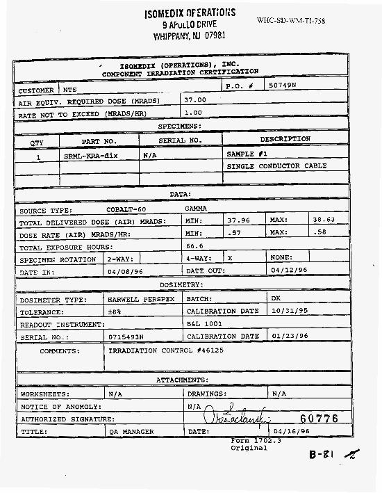
WHC-SD-WM-TI-758 I so M: ED IX OF E RAT IO I4 S
9 APuLLO ERNE - . ~
WHIPPANY, KI 07981
B-sl 4 original

WHC-SD-WM-TI-7 jg lSOMEDlX OPERATlOlJS
9 APOLLO DRIVE
DOSIMETER TYPE: HARWELL PERSPEX BATCH:
TOLERANCE: 2 0 % CALIBRATION DATE
WHIPPANY, NJ 07981
DX
10/31/95
READOUT INSTRUMENT:
SERIAL NO. : 0715493N
Form 1702.3
BCL 1001
CALIBRATION DATE 01/23/96
B-8a d original
COMMENTS: IRRADIATION CONTROL 846125

IS OM ED IX OPERATI Of4 S WHC-SD-WM-TI-758 9 APuLLO DRIVE
DOSIMETER TYPE: 1 HARWELL PERSPEX TOLERANCE: ?a% READOUT INSTRUMENT:
WHIPPANY, NJ 07981
BATCH: 1 DK CALIBRATION DATE 10/31/95
B&L 1001
* IBOXEDII (OPERATIONB), INC. C O H 2 O m IRRADIATION CERTIPICZL?
SPECIMENS:
DOSIMETRY: I I
COMMENTS : IRWLDIATION CONTROL #46125
Original

I SO M ED I X 0 PE RAT1 0 I; S 9 APuLLO DRIVE
WHIPPANY, NI 07981 WHC-SD-WM-TI-758
Form 1702.3 original

WHC-SD-WM-TI-758
APPENDIX E
F’HOTOG-
Report No. Revision 0
B-l3 s

WHC-SD- WM-TI-75 8 --
TRERMAL AGING, CABLES ON SOLID MAh’DREIs, S A M P m 1 , 2 , 3 & 4
WIRE MESH MANDRELS FOR IRRADIATION, SAMPLB 1,2,3 AND 5
Report No. 50776-97N Revision 0
B - P 6
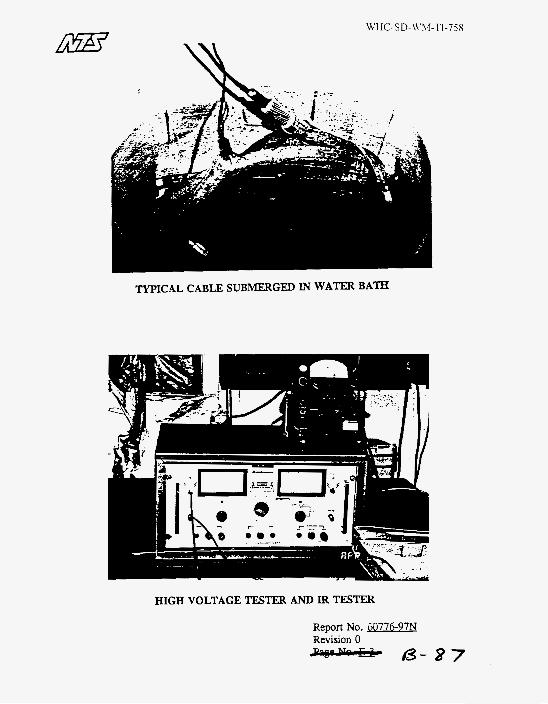
TYPICAL CABLE SUBMERGED IN WATER BATH
HIGH VOLTAGE TESTER AND IR TESTER
Report No. 3776-97N Revision 0 - 1 3 - 8 7