Embed Size (px)
Citation preview
1
®
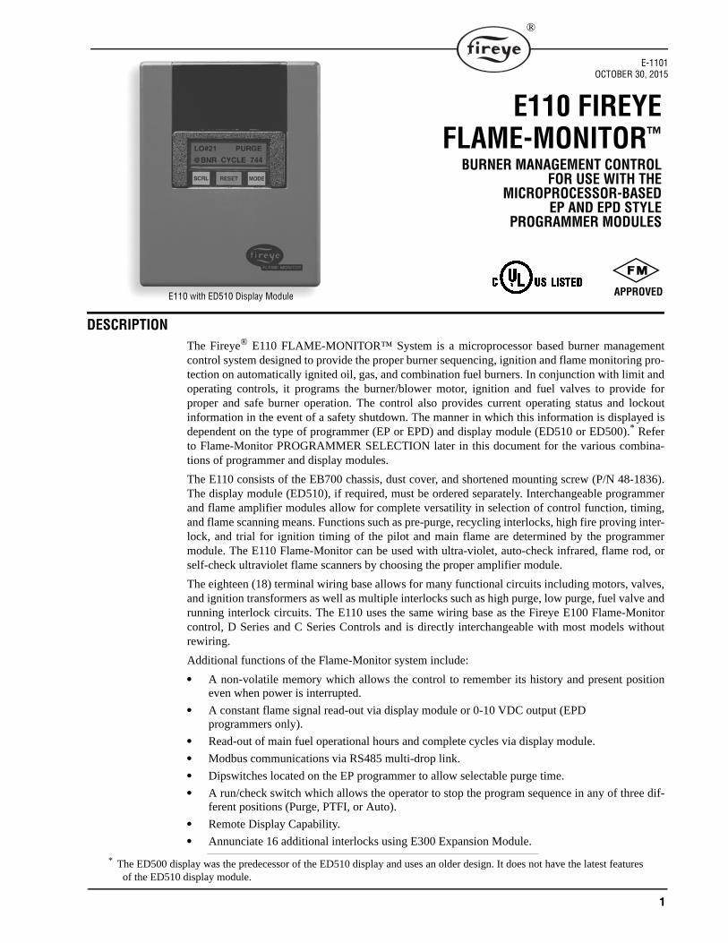
DESCRIPTION The Fireye® E110 FLAME-MONITOR™ System is a microprocessor based burner managementcontrol system designed to provide the proper burner sequencing, ignition and flame monitoring pro-tection on automatically ignited oil, gas, and combination fuel burners. In conjunction with limit andoperating controls, it programs the burner/blower motor, ignition and fuel valves to provide forproper and safe burner operation. The control also provides current operating status and lockoutinformation in the event of a safety shutdown. The manner in which this information is displayed isdependent on the type of programmer (EP or EPD) and display module (ED510 or ED500).* Referto Flame-Monitor PROGRAMMER SELECTION later in this document for the various combina-tions of programmer and display modules.
The E110 consists of the EB700 chassis, dust cover, and shortened mounting screw (P/N 48-1836).The display module (ED510), if required, must be ordered separately. Interchangeable programmerand flame amplifier modules allow for complete versatility in selection of control function, timing,and flame scanning means. Functions such as pre-purge, recycling interlocks, high fire proving inter-lock, and trial for ignition timing of the pilot and main flame are determined by the programmermodule. The E110 Flame-Monitor can be used with ultra-violet, auto-check infrared, flame rod, orself-check ultraviolet flame scanners by choosing the proper amplifier module.
The eighteen (18) terminal wiring base allows for many functional circuits including motors, valves,and ignition transformers as well as multiple interlocks such as high purge, low purge, fuel valve andrunning interlock circuits. The E110 uses the same wiring base as the Fireye E100 Flame-Monitorcontrol, D Series and C Series Controls and is directly interchangeable with most models withoutrewiring.
Additional functions of the Flame-Monitor system include:
• A non-volatile memory which allows the control to remember its history and present positioneven when power is interrupted.
• A constant flame signal read-out via display module or 0-10 VDC output (EPD programmers only).
• Read-out of main fuel operational hours and complete cycles via display module.
• Modbus communications via RS485 multi-drop link.
• Dipswitches located on the EP programmer to allow selectable purge time.
• A run/check switch which allows the operator to stop the program sequence in any of three dif-ferent positions (Purge, PTFI, or Auto).
• Remote Display Capability.
• Annunciate 16 additional interlocks using E300 Expansion Module.
* The ED500 display was the predecessor of the ED510 display and uses an older design. It does not have the latest featuresof the ED510 display module.
E110 FIREYE FLAME-MONITOR™
BURNER MANAGEMENT CONTROLFOR USE WITH THE
MICROPROCESSOR-BASEDEP AND EPD STYLE
PROGRAMMER MODULES
E-1101OCTOBER 30, 2015
APPROVEDE110 with ED510 Display Module
2
®
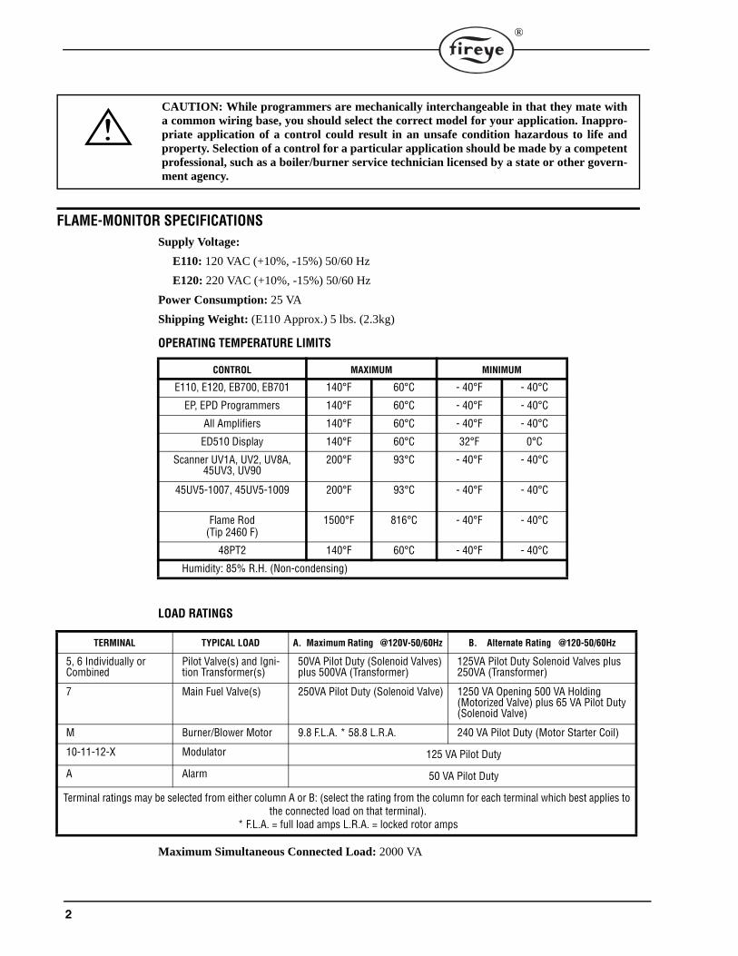
FLAME-MONITOR SPECIFICATIONSSupply Voltage:
E110: 120 VAC (+10%, -15%) 50/60 Hz
E120: 220 VAC (+10%, -15%) 50/60 Hz
Power Consumption: 25 VA
Shipping Weight: (E110 Approx.) 5 lbs. (2.3kg)
OPERATING TEMPERATURE LIMITS
LOAD RATINGS
Maximum Simultaneous Connected Load: 2000 VA
CONTROL MAXIMUM MINIMUM
E110, E120, EB700, EB701 140°F 60°C - 40°F - 40°C
EP, EPD Programmers 140°F 60°C - 40°F - 40°C
All Amplifiers 140°F 60°C - 40°F - 40°C
ED510 Display 140°F 60°C 32°F 0°C
Scanner UV1A, UV2, UV8A, 45UV3, UV90
200°F 93°C - 40°F - 40°C
45UV5-1007, 45UV5-1009 200°F 93°C - 40°F - 40°C
Flame Rod(Tip 2460 F)
1500°F 816°C - 40°F - 40°C
48PT2 140°F 60°C - 40°F - 40°C
Humidity: 85% R.H. (Non-condensing)
TERMINAL TYPICAL LOAD A. Maximum Rating @120V-50/60Hz B. Alternate Rating @120-50/60Hz
5, 6 Individually or Combined
Pilot Valve(s) and Igni-tion Transformer(s)
50VA Pilot Duty (Solenoid Valves) plus 500VA (Transformer)
125VA Pilot Duty Solenoid Valves plus 250VA (Transformer)
7 Main Fuel Valve(s) 250VA Pilot Duty (Solenoid Valve) 1250 VA Opening 500 VA Holding (Motorized Valve) plus 65 VA Pilot Duty (Solenoid Valve)
M Burner/Blower Motor 9.8 F.L.A. * 58.8 L.R.A. 240 VA Pilot Duty (Motor Starter Coil)
10-11-12-X Modulator 125 VA Pilot Duty
A Alarm 50 VA Pilot Duty
Terminal ratings may be selected from either column A or B: (select the rating from the column for each terminal which best applies to the connected load on that terminal).
* F.L.A. = full load amps L.R.A. = locked rotor amps
CAUTION: While programmers are mechanically interchangeable in that they mate witha common wiring base, you should select the correct model for your application. Inappro-priate application of a control could result in an unsafe condition hazardous to life andproperty. Selection of a control for a particular application should be made by a competentprofessional, such as a boiler/burner service technician licensed by a state or other govern-ment agency.
3
®
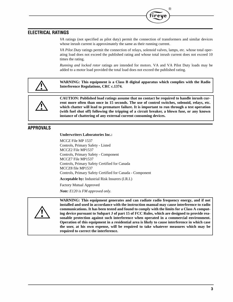
ELECTRICAL RATINGSVA ratings (not specified as pilot duty) permit the connection of transformers and similar deviceswhose inrush current is approximately the same as their running current.
VA Pilot Duty ratings permit the connection of relays, solenoid valves, lamps, etc. whose total oper-ating load does not exceed the published rating and whose total inrush current does not exceed 10times the rating.
Running and locked rotor ratings are intended for motors. VA and VA Pilot Duty loads may beadded to a motor load provided the total load does not exceed the published rating.
WARNING: This equipment is a Class B digital apparatus which complies with the RadioInterference Regulations, CRC c.1374.
CAUTION: Published load ratings assume that no contact be required to handle inrush cur-rent more often than once in 15 seconds. The use of control switches, solenoid, relays, etc.which chatter will lead to premature failure. It is important to run through a test operation(with fuel shut off) following the tripping of a circuit breaker, a blown fuse, or any knowninstance of chattering of any external current consuming devices.
APPROVALSUnderwriters Laboratories Inc.:
MCCZ File MP 1537Controls, Primary Safety - ListedMCCZ2 File MP1537Controls, Primary Safety - ComponentMCCZ7 File MP1537Controls, Primary Safety Certified for CanadaMCCZ8 file MP1537Controls, Primary Safety Certified for Canada - Component
Acceptable by: Industrial Risk Insurers (I.R.I.)
Factory Mutual Approved
Note: E120 is FM approved only.
WARNING: This equipment generates and can radiate radio frequency energy, and if notinstalled and used in accordance with the instruction manual may cause interference to radiocommunications. It has been tested and found to comply with the limits for a Class A comput-ing device pursuant to Subpart J of part 15 of FCC Rules, which are designed to provide rea-sonable protection against such interference when operated in a commercial environment.Operation of this equipment in a residential area is likely to cause interference in which casethe user, at his own expense, will be required to take whatever measures which may berequired to correct the interference.
4
®
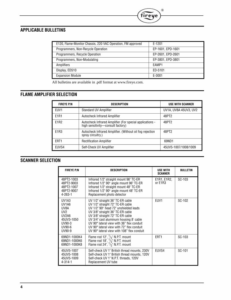
APPLICABLE BULLETINS
All bulletins are available in .pdf format at www.fireye.com.
FLAME AMPLIFIER SELECTION
SCANNER SELECTION
E120, Flame-Monitor Chassis, 220 VAC Operation, FM approved E-1201
Programmers, Non-Recycle Operation EP-1601, EPD-1601
Programmers, Recycle Operation EP-2601, EPD-2601
Programmers, Non-Modulating EP-3801, EPD-3801
Amplifiers EAMP1
Display, ED510 ED-5101
Expansion Module E-3001
FIREYE P/N DESCRIPTION USE WITH SCANNER
EUV1 Standard UV Amplifier UV1A, UV8A 45UV3, UV2
E1R1 Autocheck Infrared Amplifier 48PT2
E1R2 Autocheck Infrared Amplifier (For special applications - high sensitivity—consult factory)
48PT2
E1R3 Autocheck Infrared Amplifier. (Without oil fog rejection spray circuitry.)
48PT2
ERT1 Rectification Amplifier 69ND1
EUVS4 Self-Check UV Amplifier 45UV5-1007/1008/1009
FIREYE P/N DESCRIPTION USE WITH SCANNER
BULLETIN
48PT2-100348PT2-900348PT2-100748PT2-90074-263-1
Infrared 1/2" straight mount 96" TC-ERInfrared 1/2" 90 angle mount 96" TC-ERInfrared 1/2" straight mount 48" TC-ERInfrared 1/2" 90 angle mount 48" TC-ERReplacement photo detector
E1R1, E1R2, or E1R3
SC-103
UV1A3UV1A6UV8AUV2UV2A645UV3-1050UV90-3UV90-6UV90-9
UV 1/2" straight 36" TC-ER cableUV 1/2" straight 72" TC-ER cableUV 1/2" 90 head 72" unshielded leadsUV 3/8" straight 36" TC-ER cableUV 3/8" straight 72" TC-ER cableUV 3/4" cast aluminum housing 8' cableUV 90° lateral view with 36” flex conduitUV 90° lateral view with 72” flex conduitUV 90° lateral view with 108” flex conduit
EUV1 SC-102
69ND1-1000K469ND1-1000K669ND1-1000K8
Flame rod 12", 1/2" N.P.T. mountFlame rod 18", 1/2" N.P.T. mountFlame rod 24", 1/2" N.P.T. mount
ERT1 SC-103
45UV5-100745UV5-100845UV5-10094-314-1
Self-check UV 1" British thread mounts, 230VSelf-check UV 1" British thread mounts, 120VSelf-check UV 1" N.P.T. threads, 120VReplacement UV tube
EUVS4 SC-101
5
®
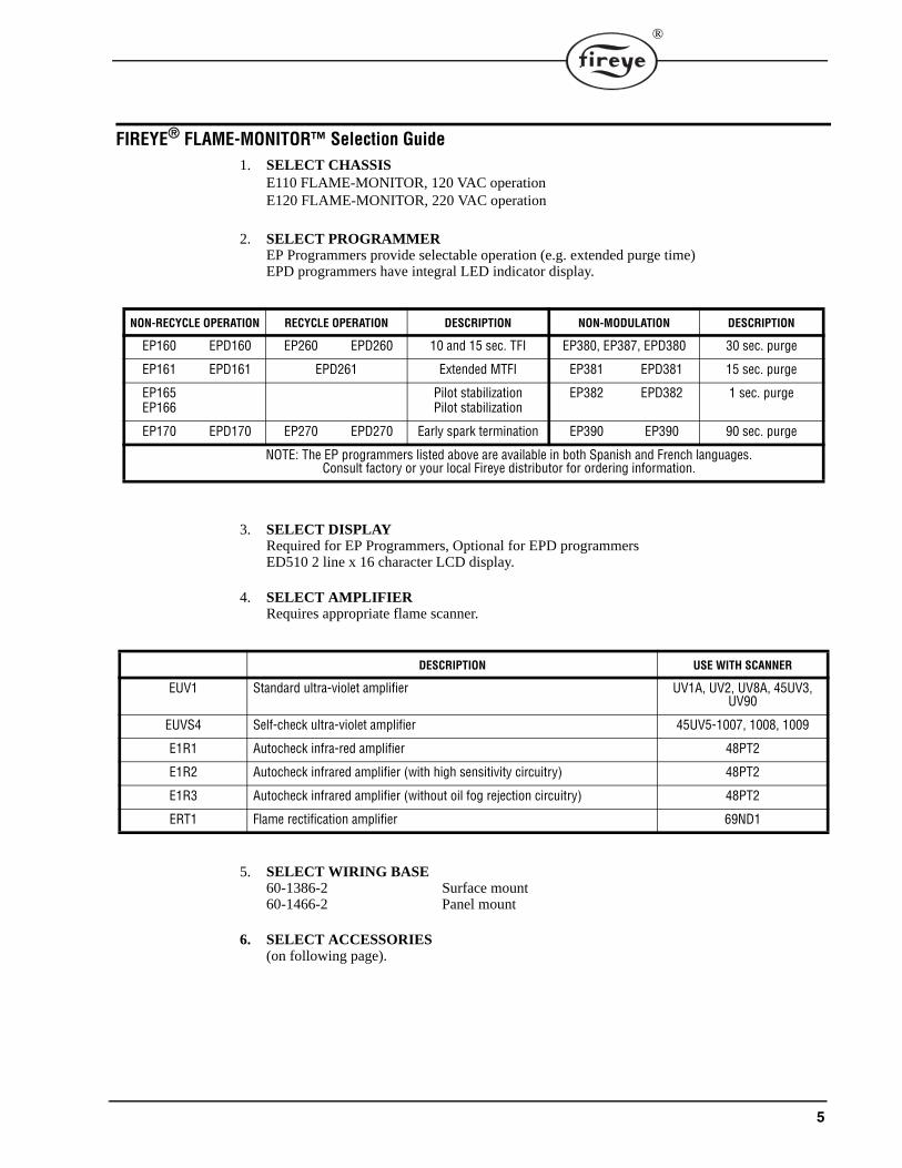
FIREYE® FLAME-MONITOR™ Selection Guide1. SELECT CHASSIS
E110 FLAME-MONITOR, 120 VAC operationE120 FLAME-MONITOR, 220 VAC operation
2. SELECT PROGRAMMEREP Programmers provide selectable operation (e.g. extended purge time)EPD programmers have integral LED indicator display.
3. SELECT DISPLAY Required for EP Programmers, Optional for EPD programmersED510 2 line x 16 character LCD display.
4. SELECT AMPLIFIER Requires appropriate flame scanner.
5. SELECT WIRING BASE60-1386-2 Surface mount60-1466-2 Panel mount
6. SELECT ACCESSORIES(on following page).
NON-RECYCLE OPERATION RECYCLE OPERATION DESCRIPTION NON-MODULATION DESCRIPTION
EP160 EPD160 EP260 EPD260 10 and 15 sec. TFI EP380, EP387, EPD380 30 sec. purge
EP161 EPD161 EPD261 Extended MTFI EP381 EPD381 15 sec. purge
EP165EP166
Pilot stabilizationPilot stabilization
EP382 EPD382 1 sec. purge
EP170 EPD170 EP270 EPD270 Early spark termination EP390 EP390 90 sec. purge
NOTE: The EP programmers listed above are available in both Spanish and French languages. Consult factory or your local Fireye distributor for ordering information.
DESCRIPTION USE WITH SCANNER
EUV1 Standard ultra-violet amplifier UV1A, UV2, UV8A, 45UV3, UV90
EUVS4 Self-check ultra-violet amplifier 45UV5-1007, 1008, 1009
E1R1 Autocheck infra-red amplifier 48PT2
E1R2 Autocheck infrared amplifier (with high sensitivity circuitry) 48PT2
E1R3 Autocheck infrared amplifier (without oil fog rejection circuitry) 48PT2
ERT1 Flame rectification amplifier 69ND1
6
®
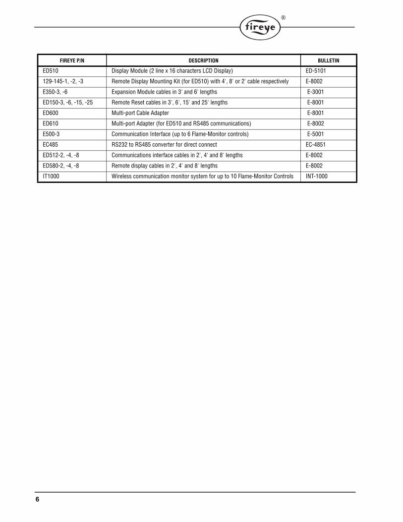
FIREYE P/N DESCRIPTION BULLETIN
ED510 Display Module (2 line x 16 characters LCD Display) ED-5101
129-145-1, -2, -3 Remote Display Mounting Kit (for ED510) with 4', 8' or 2' cable respectively E-8002
E350-3, -6 Expansion Module cables in 3' and 6' lengths E-3001
ED150-3, -6, -15, -25 Remote Reset cables in 3', 6', 15' and 25' lengths E-8001
ED600 Multi-port Cable Adapter E-8001
ED610 Multi-port Adapter (for ED510 and RS485 communications) E-8002
E500-3 Communication Interface (up to 6 Flame-Monitor controls) E-5001
EC485 RS232 to RS485 converter for direct connect EC-4851
ED512-2, -4, -8 Communications interface cables in 2', 4' and 8' lengths E-8002
ED580-2, -4, -8 Remote display cables in 2', 4' and 8' lengths E-8002
IT1000 Wireless communication monitor system for up to 10 Flame-Monitor Controls INT-1000
7
®
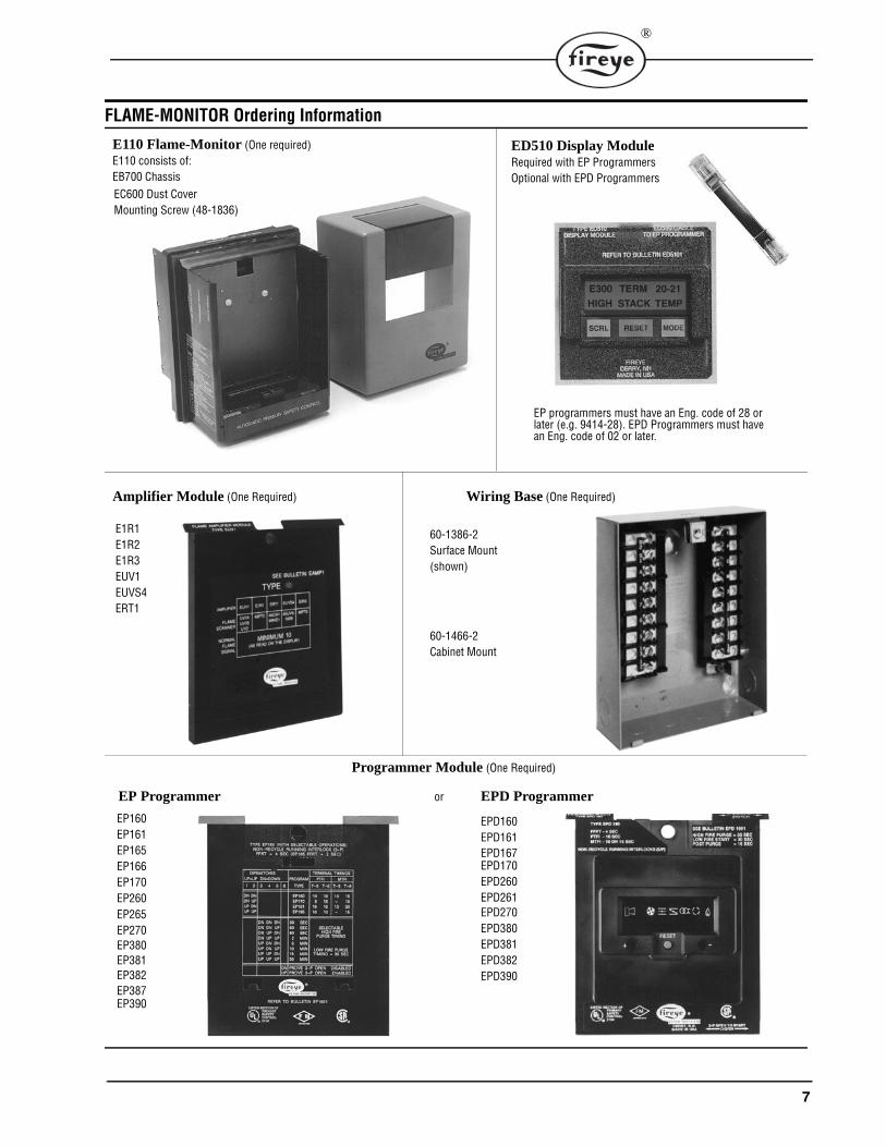
FLAME-MONITOR Ordering Information
E110 Flame-Monitor (One required) ED510 Display ModuleRequired with EP ProgrammersOptional with EPD Programmers
Amplifier Module (One Required) Wiring Base (One Required)
E1R1E1R2E1R3EUV1EUVS4ERT1
60-1386-2
60-1466-2
Programmer Module (One Required)
EP Programmer
EP160
EPD Programmeror
EP161EP165EP166EP170EP260EP265EP270EP380EP381EP382
EPD160EPD161
EPD170EPD260EPD261EPD270EPD380EPD381EPD382EPD390
E110 consists of:EB700 ChassisEC600 Dust CoverMounting Screw (48-1836)
Surface Mount(shown)
Cabinet Mount
EP programmers must have an Eng. code of 28 or later (e.g. 9414-28). EPD Programmers must have an Eng. code of 02 or later.
EP387
EPD167
EP390
8
®
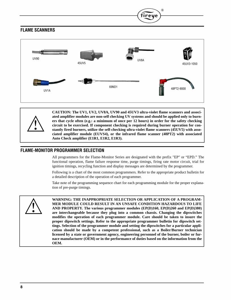
FLAME SCANNERS
CAUTION: The UV1, UV2, UV8A, UV90 and 45UV3 ultra-violet flame scanners and associ-ated amplifier modules are non-self checking UV systems and should be applied only to burn-ers that cycle often (e.g.: a minimum of once per 12 hours) in order for the safety checkingcircuit to be exercised. If component checking is required during burner operation for con-stantly fired burners, utilize the self-checking ultra-violet flame scanners (45UV5) with asso-ciated amplifier module (EUVS4), or the infrared flame scanner (48PT2) with associatedAuto Check amplifier (E1R1, E1R2, E1R3).
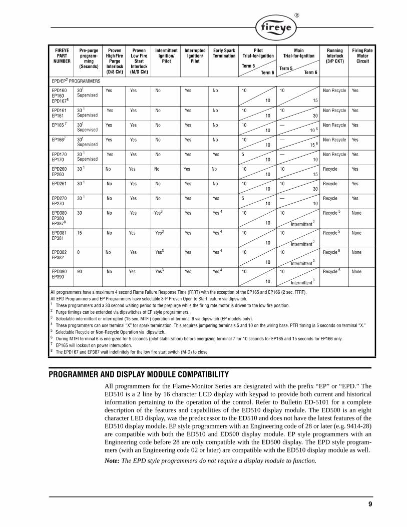
FLAME-MONITOR PROGRAMMER SELECTIONAll programmers for the Flame-Monitor Series are designated with the prefix "EP" or “EPD.” Thefunctional operation, flame failure response time, purge timings, firing rate motor circuit, trial forignition timings, recycling function and display messages are determined by the programmer.
Following is a chart of the most common programmers. Refer to the appropriate product bulletin fora detailed description of the operation of each programmer.
Take note of the programming sequence chart for each programming module for the proper explana-tion of pre-purge timings.
WARNING: THE INAPPROPRIATE SELECTION OR APPLICATION OF A PROGRAM-MER MODULE COULD RESULT IN AN UNSAFE CONDITION HAZARDOUS TO LIFEAND PROPERTY. The various programmer modules (EP(D)160, EP(D)260 and EP(D)380)are interchangeable because they plug into a common chassis. Changing the dipswitchesmodifies the operation of each programmer module. Care should be taken to insure theproper dipswitch settings. Refer to the appropriate programmer bulletin for dipswitch set-tings. Selection of the programmer module and setting the dipswitches for a particular appli-cation should be made by a competent professional, such as a Boiler/Burner technicianlicensed by a state or government agency, engineering personnel of the burner, boiler or fur-nace manufacturer (OEM) or in the performance of duties based on the information from theOEM.
UV9045UV5
UV8A45UV3-1050
UV1A69ND1 48PT2-9000
9
®
PROGRAMMER AND DISPLAY MODULE COMPATIBILITYAll programmers for the Flame-Monitor Series are designated with the prefix “EP” or “EPD.” TheED510 is a 2 line by 16 character LCD display with keypad to provide both current and historicalinformation pertaining to the operation of the control. Refer to Bulletin ED-5101 for a completedescription of the features and capabilities of the ED510 display module. The ED500 is an eightcharacter LED display, was the predecessor to the ED510 and does not have the latest features of theED510 display module. EP style programmers with an Engineering code of 28 or later (e.g. 9414-28)are compatible with both the ED510 and ED500 display module. EP style programmers with anEngineering code before 28 are only compatible with the ED500 display. The EPD style program-mers (with an Engineering code 02 or later) are compatible with the ED510 display module as well.
Note: The EPD style programmers do not require a display module to function.
FIREYE PART
NUMBER
Pre-purge program-
ming(Seconds)
Proven High Fire
Purge Interlock (D/8 Ckt)
Proven Low Fire
Start Interlock (M/D Ckt)
Intermittent Ignition/
Pilot
Interrupted Ignition/
Pilot
Early Spark Termination
Pilot Trial-for-Ignition
Main Trial-for-Ignition
Running Interlock (3/P CKT)
Firing Rate Motor Circuit
EPD/EP2 PROGRAMMERS
EPD160EP160EPD1678
301
SupervisedYes Yes No Yes No 10
10
10
15
Non Recycle Yes
EPD161EP161
30 1Supervised
Yes Yes No Yes No 1010
1030
Non Recycle Yes
EP165 7 301
SupervisedYes Yes No Yes No 10
10—
10 6Non Recycle Yes
EP1667 301
SupervisedYes Yes No Yes No 10
10—
15 6Non Recycle Yes
EPD170EP170
30 1Supervised
Yes Yes No Yes Yes 510
—10
Non Recycle Yes
EPD260EP260
30 1 No Yes No Yes No 1010
1015
Recycle Yes
EPD261 30 1 No Yes No Yes No 1010
1030
Recycle Yes
EPD270EP270
30 1 No Yes No Yes Yes 510
—10
Recycle Yes
EPD380EP380EP3878
30 No Yes Yes3 Yes Yes 4 10
10
10
Intermittent 3
Recycle 5 None
EPD381EP381
15 No Yes Yes3 Yes Yes 4 10
10
10
Intermittent 3
Recycle 5 None
EPD382EP382
0 No Yes Yes3 Yes Yes 4 10
10
10
Intermittent 3
Recycle 5 None
EPD390EP390
90 No Yes Yes3 Yes Yes 4 10
10
10
Intermittent 3
Recycle 5 None
All programmers have a maximum 4 second Flame Failure Response Time (FFRT) with the exception of the EP165 and EP166 (2 sec. FFRT).All EPD Programmers and EP Programmers have selectable 3-P Proven Open to Start feature via dipswitch.1 These programmers add a 30 second waiting period to the prepurge while the firing rate motor is driven to the low fire position.2 Purge timings can be extended via dipswitches of EP style programmers.3 Selectable intermittent or interrupted (15 sec. MTFI) operation of terminal 6 via dipswitch (EP models only).4 These programmers can use terminal “X” for spark termination. This requires jumpering terminals 5 and 10 on the wiring base. PTFI timing is 5 seconds on terminal “X.”5 Selectable Recycle or Non-Recycle Operation via dipswitch.6 During MTFI terminal 6 is energized for 5 seconds (pilot stabilization) before energizing terminal 7 for 10 seconds for EP165 and 15 seconds for EP166 only.7 EP165 will lockout on power interruption.8 The EPD167 and EP387 wait indefinitely for the low fire start switch (M-D) to close.
Term 5Term 6
Term 5Term 6
10
®
For a complete system, choose one of each of the following:
- Chassis - Flame Detector
- Programmer Module - Wiring Base
- Amplifier Module
WARNING: Installer must be trained and qualified. Follow the burner manufacturers in-structions, if supplied. Otherwise, proceed as follows:
INSTALLATION OF CONTROL
Wiring Base
Mount the wiring base on the burner or on a panel. The location should be free from excessive vibra-tion and within the specified ambient temperature rating. The base may be mounted in any angularposition.
All wiring should comply with applicable electrical codes, regulations and local ordinances. Usemoisture resistant wire suitable for at least 90 degrees C. Good electrical wiring practice should befollowed to ensure an adequate ground system. Refer to Fireye Service Note 100 separately and Gen-eral Grounding Rules, later in this document, for recommended grounding methods
A good ground system should be provided to minimize the effects of AC quality problems. A prop-erly designed ground system meeting all the safety requirements will ensure that any AC voltagequality problems, such as spikes, surges and impulses have a low impedance path to ground. A lowimpedance path to ground is required to ensure that large currents involved with any surge voltageswill follow the desired path in preferences to alternative paths, where extensive damage may occur toequipment.
Refer to suggested Wiring Diagram on page 32.
WARNING: Controls require safety limits utilizing isolated mechanical contacts. Electroniclimit switches may cause erratic operation and should be avoided.
BEFORE INSTALLING THE CONTROL
CAUTION: Ensure that electric power is turned off. Refer to SN-100 for recommendedgrounding techniques.
Be aware that power to some interlocks (operating controls, air flow switches, modulating cir-cuits, etc.) may be derived from sources other than what is controlling the Flame-Monitor.
If either a ground or a short circuit is detected, it must be eliminated before the control is pluggedinto the wiring base and power turned on.
Test the electrical field wiring for short circuits and grounds. The recommended method requires theuse of an ohmmeter set on its lowest resistance scale.
Note: When using ultra-violet or infrared scanning, be sure to remove any jumpers on the wiringbase which ground the S2 terminal.
1. Touch the meter probes together and calibrate accurately to ensure a reliable test.
2. Disconnect the neutral wire (L2) from the control system at the power source. Clip one metertest lead to the grounded green terminal on the lower right side of the wiring base and with theother probe touch each other terminal. At no time should the meters show continuity or read 0ohms.
11
®
3. Reconnect the neutral wire (L2) at the power source. Remove the test probe from the groundedterminal and reconnect it to Terminal L2 in the wiring base. With the other probe, touch eachother terminal. It is normal to obtain a resistance reading on the meter at some terminals duringthis test as there are resistive loads (coils, transformers, lamps, etc.) connected whose normalDC resistance may be less than 5 ohms. However, at no time should the test meter read zeroohms.
CAUTION: Restore power for the following test.
4. With Flame-Monitor removed, measure voltage from L2 to all other terminals. Reading shouldbe zero on all terminals except Ll.
INSTALLING THE CONTROL
CAUTION: Electric power must be turned off during installation.
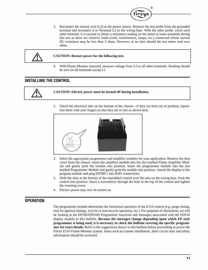
1. Check the electrical tabs on the bottom of the chassis—if they are bent out of position, reposi-tion them with your fingers so that they are in line as shown here.
2. Select the appropriate programmer and amplifier modules for your application. Remove the dustcover from the chassis. Insert the amplifier module into the slot marked Flame Amplifier Mod-ule and gently push the module into position. Insert the programmer module into the slotmarked Programmer Module and gently push the module into position. Attach the display to theprogram module and plug ED580-1 into RJ45 connections.
3. Slide the slots at the bottom of the assembled control over the tabs on the wiring base. Push thecontrol into position. Insert a screwdriver through the hole in the top of the control and tightenthe retaining screw.
4. Electric power may now be turned on.
OPERATION The programmer module determines the functional operation of the E110 control (e.g. purge timing,trial for ignition timings, recycle or non-recycle operation, etc.). For purposes of illustration, we willbe looking at the EP160/EPD160 Programmer functions and messages associated with the ED510display module in this bulletin. Because the messages change depending upon which EP styleprogrammer is being used, it is necessary to check the bulletin covering the specific program-mer for exact details. Refer to the suggestions shown in this bulletin before proceeding to power theFireye E110 Flame-Monitor system. Items such as scanner installation, short circuit tests and safetyinformation should be reviewed.
12
®
CAUTION: On initial power-up and on restarts following a power failure, the control willperform self-test diagnostics for 15 seconds.
Start-Up (Normal Cycle)Note: For direct spark ignited oil burners, substitute the words Main-Oil Valve for Pilot Valve.
1. Constant 120 VAC should be available to the Ll-L2 terminals only on the wiring base.
2. The operating control circuits (Ll-13) will close, signaling the burner to start its firing sequence.
3. If the fuel valve end switch (13-3) is closed, the burner/blower motor (terminal M) circuit isenergized. The running interlock (limit) circuit (3-P) will close (e.g. all limits, interlocks, etc. areproven).
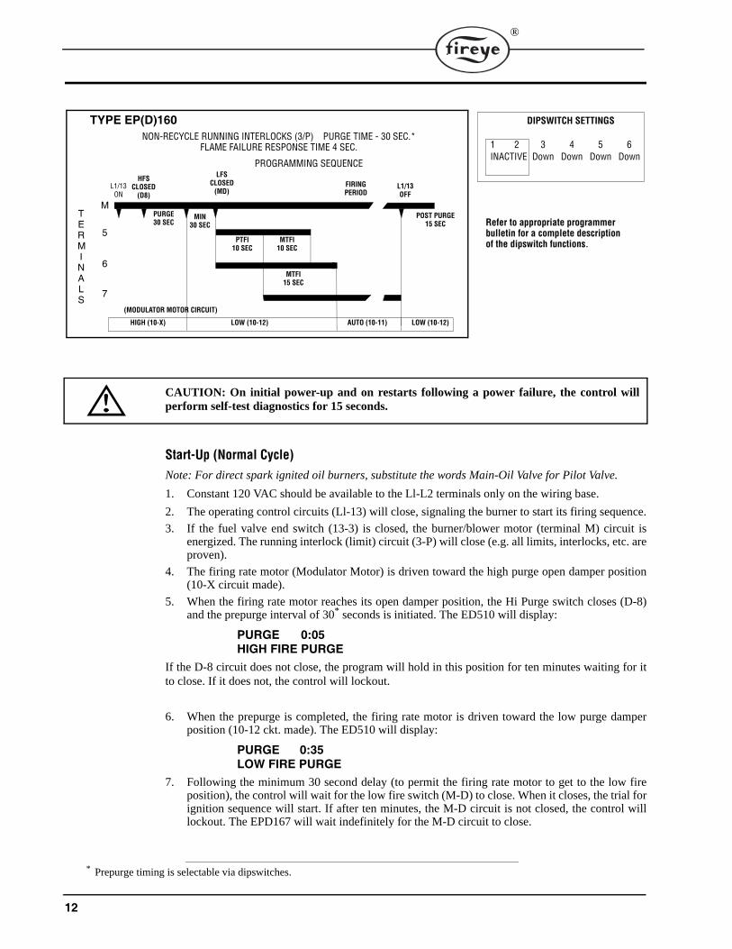
4. The firing rate motor (Modulator Motor) is driven toward the high purge open damper position(10-X circuit made).
5. When the firing rate motor reaches its open damper position, the Hi Purge switch closes (D-8)and the prepurge interval of 30* seconds is initiated. The ED510 will display:
PURGE 0:05HIGH FIRE PURGE
If the D-8 circuit does not close, the program will hold in this position for ten minutes waiting for itto close. If it does not, the control will lockout.
6. When the prepurge is completed, the firing rate motor is driven toward the low purge damperposition (10-12 ckt. made). The ED510 will display:
PURGE 0:35LOW FIRE PURGE
7. Following the minimum 30 second delay (to permit the firing rate motor to get to the low fireposition), the control will wait for the low fire switch (M-D) to close. When it closes, the trial forignition sequence will start. If after ten minutes, the M-D circuit is not closed, the control willlockout. The EPD167 will wait indefinitely for the M-D circuit to close.
* Prepurge timing is selectable via dipswitches.
TYPE EP(D)160NON-RECYCLE RUNNING INTERLOCKS (3/P) PURGE TIME - 30 SEC.*
FLAME FAILURE RESPONSE TIME 4 SEC.
PROGRAMMING SEQUENCE
L1/13ON
LFSCLOSED
(MD)FIRINGPERIOD
L1/13OFF
MTFI10 SEC
PTFI10 SEC
MTFI15 SEC
PURGE30 SEC
MTERMINALS
5
6
7
POST PURGE15 SEC
MIN30 SEC
HIGH (10-X) LOW (10-12) AUTO (10-11) LOW (10-12)
(MODULATOR MOTOR CIRCUIT)
HFSCLOSED
(D8)
DIPSWITCH SETTINGS
1 2 3 4 5 6INACTIVE Down Down Down Down
Refer to appropriate programmerbulletin for a complete descriptionof the dipswitch functions.
13
®
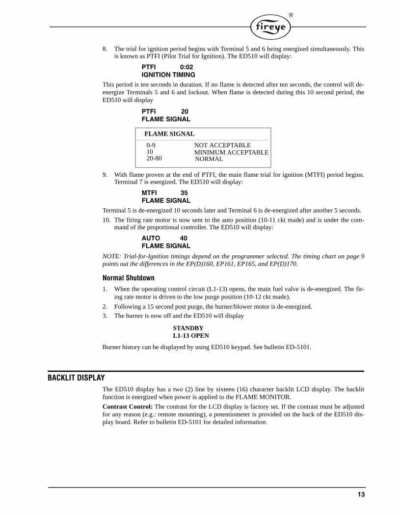
8. The trial for ignition period begins with Terminal 5 and 6 being energized simultaneously. Thisis known as PTFI (Pilot Trial for Ignition). The ED510 will display:
PTFI 0:02IGNITION TIMING
This period is ten seconds in duration. If no flame is detected after ten seconds, the control will de-energize Terminals 5 and 6 and lockout. When flame is detected during this 10 second period, theED510 will display
PTFI 20FLAME SIGNAL
9. With flame proven at the end of PTFI, the main flame trial for ignition (MTFI) period begins.Terminal 7 is energized. The ED510 will display:
MTFI 35FLAME SIGNAL
Terminal 5 is de-energized 10 seconds later and Terminal 6 is de-energized after another 5 seconds.
10. The firing rate motor is now sent to the auto position (10-11 ckt made) and is under the com-mand of the proportional controller. The ED510 will display:
AUTO 40FLAME SIGNAL
NOTE: Trial-for-Ignition timings depend on the programmer selected. The timing chart on page 9points out the differences in the EP(D)160, EP161, EP165, and EP(D)170.
Normal Shutdown1. When the operating control circuit (L1-13) opens, the main fuel valve is de-energized. The fir-
ing rate motor is driven to the low purge position (10-12 ckt made).
2. Following a 15 second post purge, the burner/blower motor is de-energized.
3. The burner is now off and the ED510 will display
STANDBYL1-13 OPEN
Burner history can be displayed by using ED510 keypad. See bulletin ED-5101.
BACKLIT DISPLAYThe ED510 display has a two (2) line by sixteen (16) character backlit LCD display. The backlitfunction is energized when power is applied to the FLAME MONITOR.
Contrast Control: The contrast for the LCD display is factory set. If the contrast must be adjustedfor any reason (e.g.: remote mounting), a potentiometer is provided on the back of the ED510 dis-play board. Refer to bulletin ED-5101 for detailed information.
FLAME SIGNAL
0-9 10 20-80 NORMAL
MINIMUM ACCEPTABLENOT ACCEPTABLE
14
®
LOCKOUTS When a safety shutdown occurs, the control will display a message indicating LOCKOUT and thereason for the lockout. The alarm circuit (Terminal “A”) will be energized. The non-volatile memorywill remember the status of the control even if a power failure occurs. By momentarily depressing thereset button on the display, the control can be reset. The button must be held down for one second andthen released. Very little force is required to do this. Do not press hard.
Safety Shutdown1. If the running interlock circuit does not close, the control will lockout and the blower motor will
be de-energized. If the interlock circuit opens during a start-up or firing period, all fuel valveswill be de-energized and the control will lockout.
2. If the proven high fire circuit (D-8) has not closed after a ten (10) minute “Hold” period at thestart of prepurge, the control will lockout.
3. If the low fire start circuit (M-D) has not closed after a ten (10) minute “Hold” period at the endof prepurge, the control will lockout.
4. If dipswitch 6 is in the “Up” position (3-P prove open to start-enabled), and the 3-P circuit isclosed at the start of the operating cycle, the control will hold for one (1) minute waiting for the3-P circuit to open. If, after one (1) minute, the 3-P circuit does not open, the control will lock-out.
5. If pilot flame is not detected during the 10 second trial for ignition period, the pilot valve andignition transformer will be de-energized and the control will lockout on safety.
6. If main flame is not detected at the end of the main flame trial for ignition period, all fuel valveswill be de-energized and the control will lockout on safety.
7. If the main flame fails during a firing cycle, all fuel valves will be de-energized within 4 secondsmaximum, after loss of flame signal and the control will lockout on safety.
8. The EP165 and EP166 programmers will lockout on a power interruption.
9. If flame is detected when the operating control (L1-13) is open, the control will wait sixty (60)seconds and then lockout if flame is still present. If the operating control closes and flame isdetected during purge, the blower motor (term M) remains energized and the purge sequence isput on hold. If the flame signal goes away within sixty (60) seconds, the control will proceedwith a normal start-up. If flame signal is still present after sixty (60) seconds, the control willlockout.
NOTE: Manual Reset is required following any safety shutdown.
NOTE: Depressing and releasing the reset button during a cycle will cause the control to shut theburner down and recycle.
DESCRIPTION OF FUNCTIONS OF OPERATING CONTROLS1. Operating Controls: Generally pressure or temperature activated, the operating control closes,
causing the burner start-up sequence to begin. When the operating control opens, the burnershuts off. The operating control is connected in the L1-13 circuit on the wiring base.
2. Limit Switches: These are generally pressure, water level or temperature activated
a. Recycle —when it is desired to stop the burner when the limit switch opens and restart itwhen the limit switch reclosed, they are connected between Terminals L1 and 13.
b. Non-Recycle —when it is necessary to stop the burner when the limit switch opens andprevent it from starting until both the limit switch recloses and the manual reset is activated,they are connected between terminals 3 and P.*
* Refer to programmer selection on page 9 to determine which programmers offer non-recycle operation of the running inter-lock circuit (ckt. 3-P).
15
®
3. Fuel Valve End Switch Interlock: This is generally an integral switch mounted on the mainfuel valve and activated by the valve stem. It is connected between Terminal 3 & 13. The fuelvalve end switch interlock prevents a burner start-up if the valve stem is not in the “valveclosed” position.
4. Purge Interlock: Generally a firing rate motor linkage position switch or a differential air-pres-sure switch, that proves a maximum purge air flow rate. It is connected between Terminals Dand 8. The purge interlock proves that the purge air flow rate is at maximum during the purge.
5. Running Interlocks: These generally are air flow switches, high and low fuel pressureswitches, oil temperature switches, atomizing media pressure switches, and excess smoke den-sity controls. These interlocks prove proper conditions for normal operation of the burner. Theyare wired in series and connected between Terminals 3 and P.
6. Low Fire Start Interlock: Generally a firing rate motor linkage position switch or a damperposition switch, will prove both the linkage and dampers are in their proper positions to beginburner light off. This switch is connected between Terminals M and D.
IMPORTANT INFORMATION — PLEASE READ CAREFULLY
DETECTING AIR FLOW SWITCH (3-P) CLOSED AFTER START
In code 39 programmers and above, the method used to detect the air flow switch closed at thebeginning of a cycle has been changed to avoid any nuisance lockouts. Previous to code 39, after theoperating control closed, the programmer waited 10 seconds for the air flow switch to close and ifnot closed would go into lockout. Beginning with code 39, the EP programmers utilize the opendamper switch interlock, D-8, to determine the wait time for the air flow switch to close. If, at thestart of a cycle after a blower turns on, the D-8 interlock is detected as closed, most likely indicatinga jumped high fire switch, the programmer allows 20 seconds for the air flow switch to close. Alter-natively, at startup, if the D-8 interlock is open, indicating the firing rate motor is at the low fire posi-tion and the damper is closed, the programmer will not check for the air flow switch closed until 10seconds after the open damper switch has closed and the purge period has begun. This means theprogrammer will send the mod motor to the high fire position, forcing the high fire damper switch toclose, and will then begin its 10 second timer to check for the air flow switch to close.
EP160 - DIP SWITCH 1
When used in conjunction with Nexus PPC5000, dip switch 1 in the UP position provides a 3 seconddelay between burner cycles. This time period is used to de-energize the blower motor, terminal M.This allows sufficient time for the PPC5000 to realize a new cycle is beginning and it can reset itsoperating parameters accordingly.
Refer to the specific programming bulletin for additional information regarding dip switch settings.
16
®
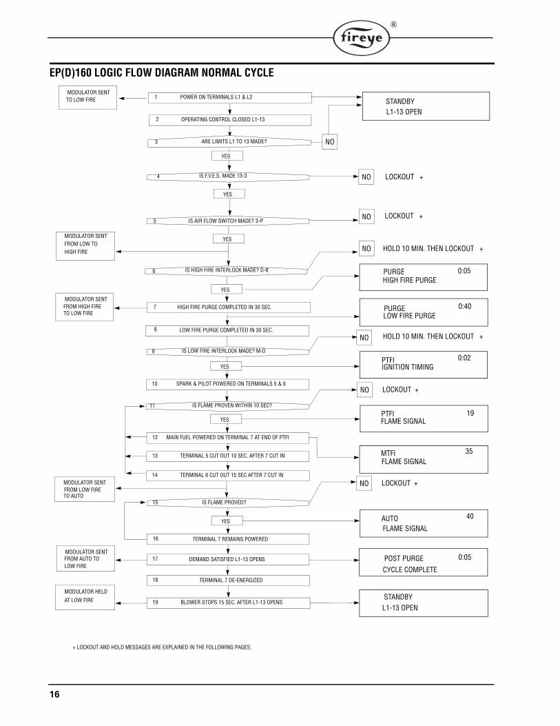
EP(D)160 LOGIC FLOW DIAGRAM NORMAL CYCLE
MODULATOR HELD
AT LOW FIRE
MODULATOR SENTFROM AUTO TO LOW FIRE
MODULATOR SENTFROM LOW FIRETO AUTO
BLOWER STOPS 15 SEC. AFTER L1-13 OPENSSTANDBYL1-13 OPEN
19
TERMINAL 7 DE-ENERGIZED18
DEMAND SATISFIED L1-13 OPENS17
TERMINAL 7 REMAINS POWERED16
TERMINAL 6 CUT OUT 15 SEC AFTER 7 CUT IN14
TERMINAL 5 CUT OUT 10 SEC. AFTER 7 CUT IN13
MAIN FUEL POWERED ON TERMINAL 7 AT END OF PTFI12
SPARK & PILOT POWERED ON TERMINALS 5 & 610
YES
YES
YES
LOW FIRE PURGE COMPLETED IN 30 SEC.8
HIGH FIRE PURGE COMPLETED IN 30 SEC.7
YES
NO
NO
NO
NO
NO
YES
YES
YES
NO
OPERATING CONTROL CLOSED L1-13
POWER ON TERMINALS L1 & L21MODULATOR SENTTO LOW FIRE
MODULATOR SENTFROM LOW TO HIGH FIRE
MODULATOR SENT FROM HIGH FIRETO LOW FIRE
NO LOCKOUT +
LOCKOUT +
HOLD 10 MIN. THEN LOCKOUT +
HOLD 10 MIN. THEN LOCKOUT +
15 IS FLAME PROVED?
IS FLAME PROVEN WITHIN 10 SEC?
IS LOW FIRE INTERLOCK MADE? M-D
ARE LIMITS L1 TO 13 MADE?3
4
5
6
POST PURGE CYCLE COMPLETE
AUTOFLAME SIGNAL
MTFIFLAME SIGNAL
PTFIFLAME SIGNAL
PTFIIGNITION TIMING
PURGEHIGH FIRE PURGE
LOCKOUT +
LOCKOUT +
0:05
0:05
0:02
19
35
40
STANDBYL1-13 OPEN
2
IS F.V.E.S. MADE 13-3
IS AIR FLOW SWITCH MADE? 3-P
IS HIGH FIRE INTERLOCK MADE? D-8
PURGELOW FIRE PURGE
0:40
+ LOCKOUT AND HOLD MESSAGES ARE EXPLAINED IN THE FOLLOWING PAGES.
9
11

17
®
ED510 MESSAGES
RUN MESSAGESThe operating control of the FLAME-MONITOR (terminals L1-13) is open.
Firing rate motor sent to high fire (term. 10-X made), purge timing displayedupper right hand corner.
Firing rate motor sent to low fire (term. 10-12 made), purge timing displayed inupper right hand corner.
PTFI timing started. Pilot not proven yet. PTFI timing displayed in upper righthand corner.
Pilot flame proven during PTFI. Flame signal strength displayed in upper righthand corner.
Main flame proven during MTFI. Flame signal strength displayed in upper righthand corner.
Modulator motor sent to auto position (term 10-11 made). Flame signal strengthdisplayed in upper right hand corner.
Demand satisfied. L1-13 open. Blower motor de-energized 15 seconds after L1-13opens.
HOLD MESSAGESDipswitch #6 (3-P Proven Open to Start) is set in the Up position (Enabled). At thestart of the cycle, the 3-P circuit was closed. It will hold in this position for 60 sec-onds and then lockout if the 3-P circuit does not open.
The control has driven the firing rate motor to high purge (term. 10-X made) and iswaiting for the high fire switch (term. D-8) to close. It will hold this position forten (10) minutes and then lockout if the D-8 circuit does not close. Applies toEP(D)160, EP(D)161, EP165, EP166, EPD167 and EP(D)170 programmers.
Dipswitch #6 (3-P Proven Open to Start) is set in the Up position (Enabled). At thestart of a cycle the D-8 circuit was closed. It will hold in this position for 30 sec-onds and then lockout if the D-8 circuit does not open. Possible solution is toremove jumper from D-8 circuit or properly set the firing rate motor and switches.Applies to EP(D)160, EP(D)161, EP165, EP166, EPD167 and EP(D)170 pro-grammers
Dipswitch #6 (3-P Proven Open to Start) is set in the Up position (Enabled). At theend of high fire purge and beginning of low fire start, the M-D circuit is closed. Itwill hold in this position for 30 seconds and then lockout if the M-D circuit doesnot open. The solution is to remove jumper from the M-D circuit or properly setthe firing rate motor and switches. Applies to EP(D)160, EP(D)161, EP165,EP166, EPD167 and EP(D)170 programmers
STANDBYL1-13 OPEN
PURGE 0:05HIGH FIRE PURGE
PURGE 0:35LOW FIRE PURGE
PTFI 0:02IGNITION TIMING
PTFI 19FLAME SIGNAL
MTFI 25FLAME SIGNAL
AUTO 40FLAME SIGNAL
POST PURGE 0:05CYCLE COMPLETE
HOLD STANDBY 0:233-P INTLK CLOSED
HOLD PURGE 0:00D-8 LIMIT OPEN
HOLD PURGE 0:00D-8 LIMIT CLOSED
HOLD PURGE 0:30M-D LIMIT CLOSED
18
®
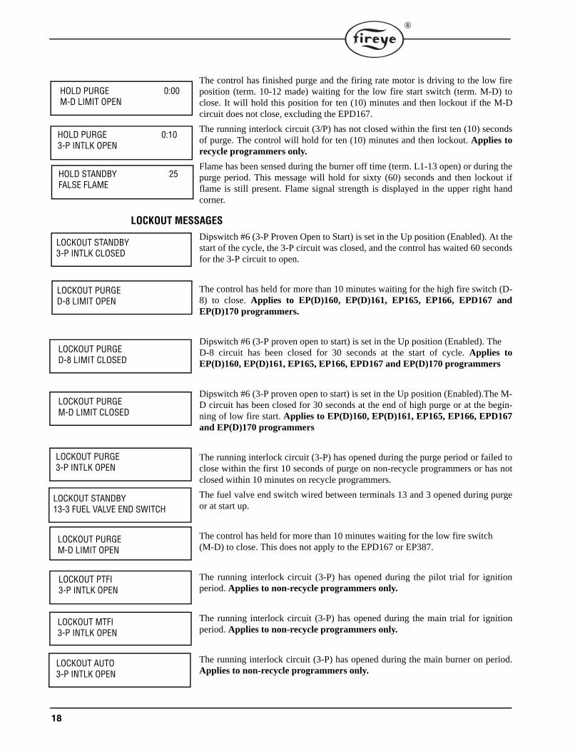
The control has finished purge and the firing rate motor is driving to the low fireposition (term. 10-12 made) waiting for the low fire start switch (term. M-D) toclose. It will hold this position for ten (10) minutes and then lockout if the M-Dcircuit does not close, excluding the EPD167.
The running interlock circuit (3/P) has not closed within the first ten (10) secondsof purge. The control will hold for ten (10) minutes and then lockout. Applies torecycle programmers only.
Flame has been sensed during the burner off time (term. L1-13 open) or during thepurge period. This message will hold for sixty (60) seconds and then lockout ifflame is still present. Flame signal strength is displayed in the upper right handcorner.
LOCKOUT MESSAGESDipswitch #6 (3-P Proven Open to Start) is set in the Up position (Enabled). At thestart of the cycle, the 3-P circuit was closed, and the control has waited 60 secondsfor the 3-P circuit to open.
The control has held for more than 10 minutes waiting for the high fire switch (D-8) to close. Applies to EP(D)160, EP(D)161, EP165, EP166, EPD167 andEP(D)170 programmers.
Dipswitch #6 (3-P proven open to start) is set in the Up position (Enabled). The D-8 circuit has been closed for 30 seconds at the start of cycle. Applies toEP(D)160, EP(D)161, EP165, EP166, EPD167 and EP(D)170 programmers
Dipswitch #6 (3-P proven open to start) is set in the Up position (Enabled).The M-D circuit has been closed for 30 seconds at the end of high purge or at the begin-ning of low fire start. Applies to EP(D)160, EP(D)161, EP165, EP166, EPD167and EP(D)170 programmers
The running interlock circuit (3-P) has opened during the purge period or failed toclose within the first 10 seconds of purge on non-recycle programmers or has notclosed within 10 minutes on recycle programmers.
The fuel valve end switch wired between terminals 13 and 3 opened during purgeor at start up.
The control has held for more than 10 minutes waiting for the low fire switch (M-D) to close. This does not apply to the EPD167 or EP387.
The running interlock circuit (3-P) has opened during the pilot trial for ignitionperiod. Applies to non-recycle programmers only.
The running interlock circuit (3-P) has opened during the main trial for ignitionperiod. Applies to non-recycle programmers only.
The running interlock circuit (3-P) has opened during the main burner on period.Applies to non-recycle programmers only.
HOLD PURGE 0:00M-D LIMIT OPEN
HOLD PURGE 0:103-P INTLK OPEN
HOLD STANDBY 25FALSE FLAME
LOCKOUT STANDBY3-P INTLK CLOSED
LOCKOUT PURGED-8 LIMIT OPEN
LOCKOUT PURGED-8 LIMIT CLOSED
LOCKOUT PURGEM-D LIMIT CLOSED
LOCKOUT PURGE3-P INTLK OPEN
LOCKOUT STANDBY13-3 FUEL VALVE END SWITCH
LOCKOUT PURGEM-D LIMIT OPEN
LOCKOUT PTFI3-P INTLK OPEN
LOCKOUT MTFI3-P INTLK OPEN
LOCKOUT AUTO3-P INTLK OPEN
19
®
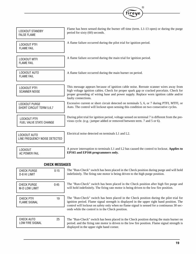
Flame has been sensed during the burner off time (term. L1-13 open) or during the purgeperiod for sixty (60) seconds.
A flame failure occurred during the pilot trial for ignition period.
A flame failure occurred during the main trial for ignition period.
A flame failure occurred during the main burner on period.
This message appears because of ignition cable noise. Reroute scanner wires away fromhigh voltage ignition cables. Check for proper spark gap or cracked porcelain. Check forproper grounding of wiring base and power supply. Replace worn ignition cable and/orfaulty connections.
Excessive current or short circuit detected on terminals 5, 6, or 7 during PTFI, MTFI, orAuto. The control will lockout upon sensing this condition on two consecutive cycles.
During pilot trial for ignition period, voltage sensed on terminal 7 is different from the pre-vious cycle. (e.g.: jumper added or removed between term. 7 and 5 or 6).
Electrical noise detected on terminals L1 and L2.
A power interruption to terminals L1 and L2 has caused the control to lockout. Applies toEP165 and EP166 programmers only.
CHECK MESSAGESThe "Run-Check" switch has been placed in the Check position during purge and will holdindefinitely. The firing rate motor is being driven to the high purge position.
The "Run-Check" switch has been placed in the Check position after high fire purge andwill hold indefinitely. The firing rate motor is being driven to the low fire position.
The "Run-Check" switch has been placed in the Check position during the pilot trial forignition period. Flame signal strength is displayed in the upper right hand position. Thecontrol will lockout on safety only when no flame signal is sensed for a continuous 30 sec-onds while the control is in the Check position.
The "Run-Check" switch has been placed in the Check position during the main burner onperiod. and the firing rate motor is driven to the low fire position. Flame signal strength isdisplayed in the upper right hand corner.
LOCKOUT STANDBYFALSE FLAME
LOCKOUT PTFIFLAME FAIL
LOCKOUT MTFIFLAME FAIL
LOCKOUT AUTOFLAME FAIL
LOCKOUT PTFISCANNER NOISE
LOCKOUT PURGESHORT CIRCUIT TERM 5,6,7
LOCKOUT PTFIFUEL VALVE STATE CHANGE
LOCKOUT AUTOLINE FREQUENCY NOISE DETECTED
LOCKOUT AC POWER FAIL
CHECK PURGE 0:15D-8 HI LIMIT
CHECK PURGE 0:45M-D LOW LIMIT
CHECK PTFI 19FLAME SIGNAL
CHECK AUTO 25LOW FIRE SIGNAL
20
®
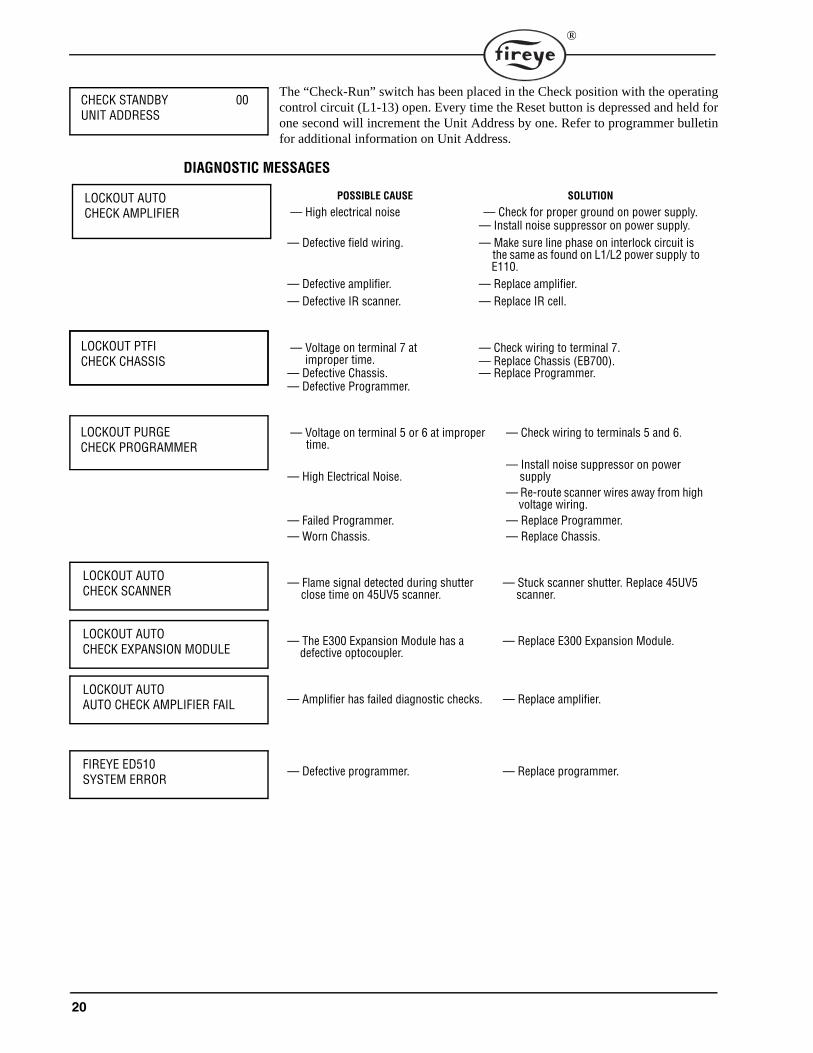
The “Check-Run” switch has been placed in the Check position with the operatingcontrol circuit (L1-13) open. Every time the Reset button is depressed and held forone second will increment the Unit Address by one. Refer to programmer bulletinfor additional information on Unit Address.
DIAGNOSTIC MESSAGES
POSSIBLE CAUSE SOLUTION
— High electrical noise — Check for proper ground on power supply.— Install noise suppressor on power supply.
— Defective field wiring. — Make sure line phase on interlock circuit isthe same as found on L1/L2 power supply to E110.
— Defective amplifier. — Replace amplifier.— Defective IR scanner. — Replace IR cell.
— Voltage on terminal 7 atimproper time.
— Defective Chassis.— Defective Programmer.
— Check wiring to terminal 7.— Replace Chassis (EB700).— Replace Programmer.
— Voltage on terminal 5 or 6 at impropertime.
— High Electrical Noise.
— Failed Programmer.— Worn Chassis.
— Check wiring to terminals 5 and 6.
— Install noise suppressor on power supply
— Re-route scanner wires away from high voltage wiring.
— Replace Programmer.— Replace Chassis.
— Flame signal detected during shutterclose time on 45UV5 scanner.
— Stuck scanner shutter. Replace 45UV5 scanner.
— The E300 Expansion Module has a defective optocoupler.
— Replace E300 Expansion Module.
— Amplifier has failed diagnostic checks. — Replace amplifier.
— Defective programmer. — Replace programmer.
CHECK STANDBY 00UNIT ADDRESS
LOCKOUT AUTOCHECK AMPLIFIER
LOCKOUT PTFICHECK CHASSIS
LOCKOUT PURGECHECK PROGRAMMER
LOCKOUT AUTOCHECK SCANNER
LOCKOUT AUTOCHECK EXPANSION MODULE
LOCKOUT AUTOAUTO CHECK AMPLIFIER FAIL
FIREYE ED510SYSTEM ERROR
21
®
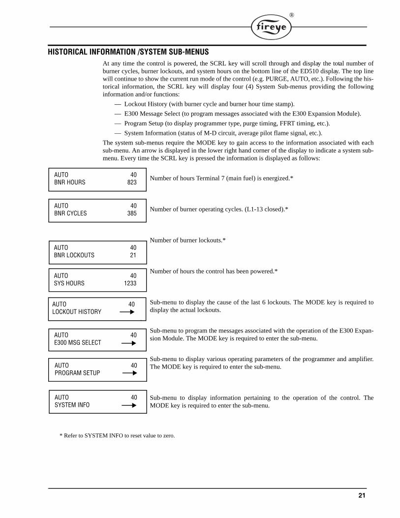
HISTORICAL INFORMATION /SYSTEM SUB-MENUSAt any time the control is powered, the SCRL key will scroll through and display the total number ofburner cycles, burner lockouts, and system hours on the bottom line of the ED510 display. The top linewill continue to show the current run mode of the control (e.g. PURGE, AUTO, etc.). Following the his-torical information, the SCRL key will display four (4) System Sub-menus providing the followinginformation and/or functions:
— Lockout History (with burner cycle and burner hour time stamp).
— E300 Message Select (to program messages associated with the E300 Expansion Module).
— Program Setup (to display programmer type, purge timing, FFRT timing, etc.).
— System Information (status of M-D circuit, average pilot flame signal, etc.).
The system sub-menus require the MODE key to gain access to the information associated with eachsub-menu. An arrow is displayed in the lower right hand corner of the display to indicate a system sub-menu. Every time the SCRL key is pressed the information is displayed as follows:
Number of hours Terminal 7 (main fuel) is energized.*
Number of burner operating cycles. (L1-13 closed).*
Number of burner lockouts.*
Number of hours the control has been powered.*
Sub-menu to display the cause of the last 6 lockouts. The MODE key is required todisplay the actual lockouts.
Sub-menu to program the messages associated with the operation of the E300 Expan-sion Module. The MODE key is required to enter the sub-menu.
Sub-menu to display various operating parameters of the programmer and amplifier.The MODE key is required to enter the sub-menu.
Sub-menu to display information pertaining to the operation of the control. TheMODE key is required to enter the sub-menu.
* Refer to SYSTEM INFO to reset value to zero.
AUTO 40BNR HOURS 823
AUTO 40BNR CYCLES 385
AUTO 40BNR LOCKOUTS 21
AUTO 40SYS HOURS 1233
AUTO 40LOCKOUT HISTORY
AUTO 40E300 MSG SELECT
AUTO 40PROGRAM SETUP
AUTO 40SYSTEM INFO
22
®
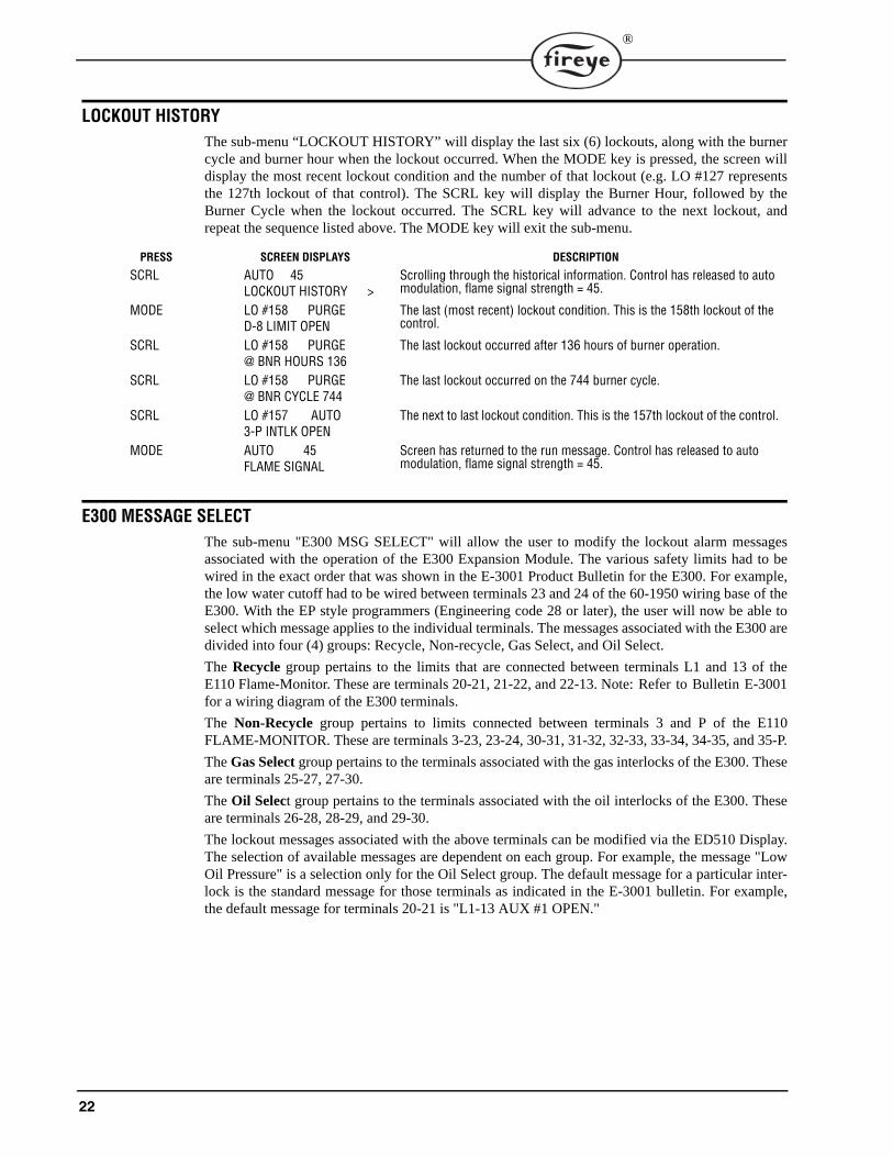
LOCKOUT HISTORY The sub-menu “LOCKOUT HISTORY” will display the last six (6) lockouts, along with the burnercycle and burner hour when the lockout occurred. When the MODE key is pressed, the screen willdisplay the most recent lockout condition and the number of that lockout (e.g. LO #127 representsthe 127th lockout of that control). The SCRL key will display the Burner Hour, followed by theBurner Cycle when the lockout occurred. The SCRL key will advance to the next lockout, andrepeat the sequence listed above. The MODE key will exit the sub-menu.
E300 MESSAGE SELECTThe sub-menu "E300 MSG SELECT" will allow the user to modify the lockout alarm messagesassociated with the operation of the E300 Expansion Module. The various safety limits had to bewired in the exact order that was shown in the E-3001 Product Bulletin for the E300. For example,the low water cutoff had to be wired between terminals 23 and 24 of the 60-1950 wiring base of theE300. With the EP style programmers (Engineering code 28 or later), the user will now be able toselect which message applies to the individual terminals. The messages associated with the E300 aredivided into four (4) groups: Recycle, Non-recycle, Gas Select, and Oil Select.
The Recycle group pertains to the limits that are connected between terminals L1 and 13 of theE110 Flame-Monitor. These are terminals 20-21, 21-22, and 22-13. Note: Refer to Bulletin E-3001for a wiring diagram of the E300 terminals.
The Non-Recycle group pertains to limits connected between terminals 3 and P of the E110FLAME-MONITOR. These are terminals 3-23, 23-24, 30-31, 31-32, 32-33, 33-34, 34-35, and 35-P.
The Gas Select group pertains to the terminals associated with the gas interlocks of the E300. Theseare terminals 25-27, 27-30.
The Oil Select group pertains to the terminals associated with the oil interlocks of the E300. Theseare terminals 26-28, 28-29, and 29-30.
The lockout messages associated with the above terminals can be modified via the ED510 Display.The selection of available messages are dependent on each group. For example, the message "LowOil Pressure" is a selection only for the Oil Select group. The default message for a particular inter-lock is the standard message for those terminals as indicated in the E-3001 bulletin. For example,the default message for terminals 20-21 is "L1-13 AUX #1 OPEN."
PRESS SCREEN DISPLAYS DESCRIPTION
SCRL AUTO 45LOCKOUT HISTORY >
Scrolling through the historical information. Control has released to auto modulation, flame signal strength = 45.
MODE LO #158 PURGED-8 LIMIT OPEN
The last (most recent) lockout condition. This is the 158th lockout of the control.
SCRL LO #158 PURGE@ BNR HOURS 136
The last lockout occurred after 136 hours of burner operation.
SCRL LO #158 PURGE@ BNR CYCLE 744
The last lockout occurred on the 744 burner cycle.
SCRL LO #157 AUTO3-P INTLK OPEN
The next to last lockout condition. This is the 157th lockout of the control.
MODE AUTO 45FLAME SIGNAL
Screen has returned to the run message. Control has released to auto modulation, flame signal strength = 45.
23
®
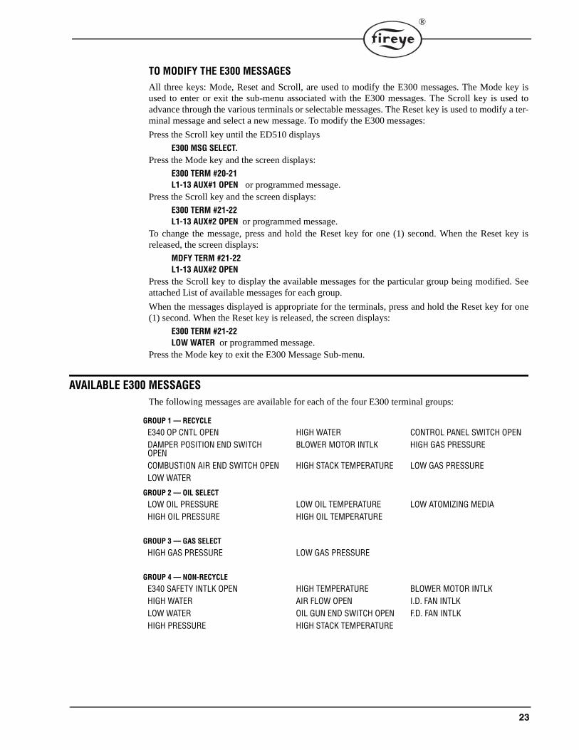
TO MODIFY THE E300 MESSAGESAll three keys: Mode, Reset and Scroll, are used to modify the E300 messages. The Mode key isused to enter or exit the sub-menu associated with the E300 messages. The Scroll key is used toadvance through the various terminals or selectable messages. The Reset key is used to modify a ter-minal message and select a new message. To modify the E300 messages:
Press the Scroll key until the ED510 displays
E300 MSG SELECT.Press the Mode key and the screen displays:
E300 TERM #20-21L1-13 AUX#1 OPEN or programmed message.
Press the Scroll key and the screen displays:
E300 TERM #21-22L1-13 AUX#2 OPEN or programmed message.
To change the message, press and hold the Reset key for one (1) second. When the Reset key isreleased, the screen displays:
MDFY TERM #21-22L1-13 AUX#2 OPEN
Press the Scroll key to display the available messages for the particular group being modified. Seeattached List of available messages for each group.
When the messages displayed is appropriate for the terminals, press and hold the Reset key for one(1) second. When the Reset key is released, the screen displays:
E300 TERM #21-22LOW WATER or programmed message.
Press the Mode key to exit the E300 Message Sub-menu.
AVAILABLE E300 MESSAGES The following messages are available for each of the four E300 terminal groups:
GROUP 1 — RECYCLE
E340 OP CNTL OPEN HIGH WATER CONTROL PANEL SWITCH OPENDAMPER POSITION END SWITCH OPEN
BLOWER MOTOR INTLK HIGH GAS PRESSURE
COMBUSTION AIR END SWITCH OPEN HIGH STACK TEMPERATURE LOW GAS PRESSURELOW WATER
GROUP 2 — OIL SELECT
LOW OIL PRESSURE LOW OIL TEMPERATURE LOW ATOMIZING MEDIAHIGH OIL PRESSURE HIGH OIL TEMPERATURE
GROUP 3 — GAS SELECT
HIGH GAS PRESSURE LOW GAS PRESSURE
GROUP 4 — NON-RECYCLE
E340 SAFETY INTLK OPEN HIGH TEMPERATURE BLOWER MOTOR INTLKHIGH WATER AIR FLOW OPEN I.D. FAN INTLKLOW WATER OIL GUN END SWITCH OPEN F.D. FAN INTLKHIGH PRESSURE HIGH STACK TEMPERATURE
24
®
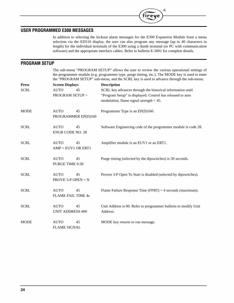
USER PROGRAMMED E300 MESSAGESIn addition to selecting the lockout alarm messages for the E300 Expansion Module from a menuselection via the ED510 display, the user can also program any message (up to 40 characters inlength) for the individual terminals of the E300 using a dumb terminal (or PC with communicationsoftware) and the appropriate interface cables. Refer to bulletin E-3001 for complete details.
PROGRAM SETUPThe sub-menu “PROGRAM SETUP” allows the user to review the various operational settings ofthe programmer module (e.g. programmer type, purge timing, etc.). The MODE key is used to enterthe “PROGRAM SETUP” sub-menu, and the SCRL key is used to advance through the sub-menu.
Press Screen Displays Description
SCRL AUTO 45 SCRL key advances through the historical information until
PROGRAM SETUP > “Program Setup” is displayed. Control has released to auto
modulation, flame signal strength = 45.
MODE AUTO 45 Programmer Type is an EP(D)160.
PROGRAMMER EP(D)160
SCRL AUTO 45 Software Engineering code of the programmer module is code 28.
ENGR CODE NO. 28
SCRL AUTO 45 Amplifier module is an EUV1 or an ERT1.
AMP = EUV1 OR ERT1
SCRL AUTO 45 Purge timing (selected by the dipswitches) is 30 seconds.
PURGE TIME 0:30
SCRL AUTO 45 Proven 3-P Open To Start is disabled (selected by dipswitches).
PROVE 3-P OPEN = N
SCRL AUTO 45 Flame Failure Response Time (FFRT) = 4 seconds (maximum).
FLAME FAIL TIME 4s
SCRL AUTO 45 Unit Address is 00. Refer to programmer bulletin to modify Unit
UNIT ADDRESS #00 Address.
MODE AUTO 45 MODE key returns to run message.
FLAME SIGNAL
25
®
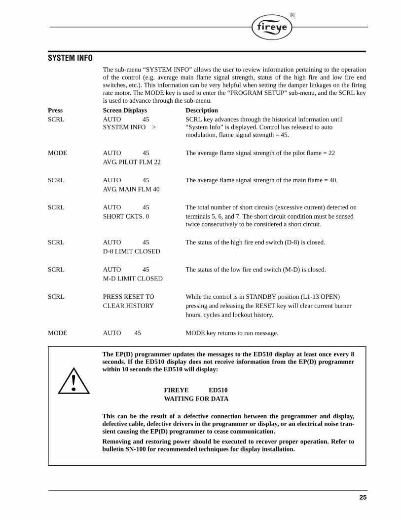
SYSTEM INFOThe sub-menu “SYSTEM INFO” allows the user to review information pertaining to the operationof the control (e.g. average main flame signal strength, status of the high fire and low fire endswitches, etc.). This information can be very helpful when setting the damper linkages on the firingrate motor. The MODE key is used to enter the “PROGRAM SETUP” sub-menu, and the SCRL keyis used to advance through the sub-menu.
Press Screen Displays Description
SCRL AUTO 45 SCRL key advances through the historical information until SYSTEM INFO > “System Info” is displayed. Control has released to auto
modulation, flame signal strength = 45.
MODE AUTO 45 The average flame signal strength of the pilot flame = 22
AVG. PILOT FLM 22
SCRL AUTO 45 The average flame signal strength of the main flame = 40.
AVG. MAIN FLM 40
SCRL AUTO 45 The total number of short circuits (excessive current) detected on
SHORT CKTS. 0 terminals 5, 6, and 7. The short circuit condition must be sensedtwice consecutively to be considered a short circuit.
SCRL AUTO 45 The status of the high fire end switch (D-8) is closed.
D-8 LIMIT CLOSED
SCRL AUTO 45 The status of the low fire end switch (M-D) is closed.
M-D LIMIT CLOSED
SCRL PRESS RESET TO While the control is in STANDBY position (L1-13 OPEN)
CLEAR HISTORY pressing and releasing the RESET key will clear current burner
hours, cycles and lockout history.
MODE AUTO 45 MODE key returns to run message.
The EP(D) programmer updates the messages to the ED510 display at least once every 8seconds. If the ED510 display does not receive information from the EP(D) programmerwithin 10 seconds the ED510 will display:
This can be the result of a defective connection between the programmer and display,defective cable, defective drivers in the programmer or display, or an electrical noise tran-sient causing the EP(D) programmer to cease communication.
Removing and restoring power should be executed to recover proper operation. Refer tobulletin SN-100 for recommended techniques for display installation.
FIREYE ED510WAITING FOR DATA
26
®
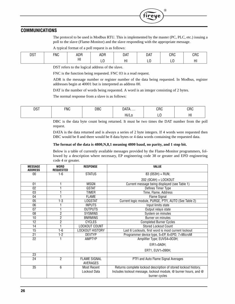
COMMUNICATIONSThe protocol to be used is Modbus RTU. This is implemented by the master (PC, PLC, etc.) issuing apoll to the slave (Flame-Monitor) and the slave responding with the appropriate message.
A typical format of a poll request is as follows:
DST refers to the logical address of the slave.
FNC is the function being requested. FNC 03 is a read request.
ADR is the message number or register number of the data being requested. In Modbus, registeraddresses begin at 40001 but is interpreted as address 00.
DAT is the number of words being requested. A word is an integer consisting of 2 bytes.
The normal response from a slave is as follows:
DBC is the data byte count being returned. It must be two times the DAT number from the pollrequest.
DATA is the data returned and is always a series of 2 byte integers. If 4 words were requested thenDBC would be 8 and there would be 8 data bytes or 4 data words containing the requested data.
The format of the data is 4800,N,8,1 meaning 4800 baud, no parity, and 1 stop bit.
Below is a table of currently available messages provided by the Flame-Monitor programmers, fol-lowed by a description where necessary, EP engineering code 38 or greater and EPD engineeringcode 4 or greater.
DST FNC ADRHI
ADR
LO
DAT
HI
DAT
LO
CRC
LO
CRC
HI
DST FNC DBC DATA….
Hi/Lo
CRC
LO
CRC
HI
MESSAGEADDRESS
WORDREQUESTED
RESPONSE VALUE
00 1-6 STATUS 83 (053H) = RUN;
202 (0CAH) = LOCKOUT01 1 MSGN Current message being displayed (see Table 1)02 1 GSTAT Defines Timer Type03 1 TIMER Time, Flame, Address04 1 FLAME Flame Signal05 1-3 LOGSTAT Current logic module, PURGE, PTFI, AUTO (See Table 2)06 1 INPUTS Input limits state07 1 OUTPUTS Output relays state08 2 SYSMINS System on minutes10 2 BNRMINS Burner on minutes12 2 CYCLES Completed Burner Cycles14 1 LOCKOUT COUNT Stored Lockout Count15 1-6 LOCKOUT HISTORY Last 6 Lockouts, first word is most current lockout21 1-2 DEVTYP Programmer device type, 5=EP, 6=EPD, 7=MicroM22 1 AMPTYP Amplifier Type; EUVS4=0C0H;
EIR1=0A0H;
ERT1, EUV1=090H;2324 2 FLAME SIGNAL
AVERAGESPTFI and Auto Flame Signal Averages
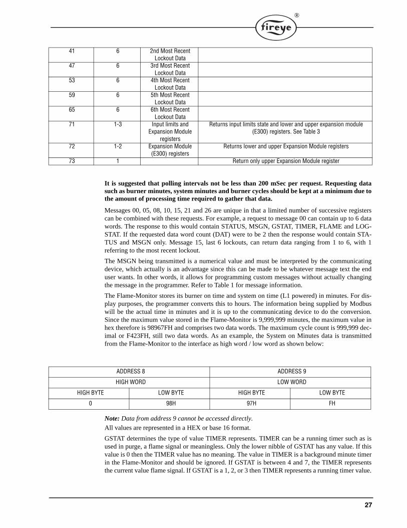
35 6 Most Recent Lockout Data
Returns complete lockout description of stored lockout history. Includes lockout message, lockout module, @ burner hours, and @
burner cycles
27
®
It is suggested that polling intervals not be less than 200 mSec per request. Requesting datasuch as burner minutes, system minutes and burner cycles should be kept at a minimum due tothe amount of processing time required to gather that data.
Messages 00, 05, 08, 10, 15, 21 and 26 are unique in that a limited number of successive registerscan be combined with these requests. For example, a request to message 00 can contain up to 6 datawords. The response to this would contain STATUS, MSGN, GSTAT, TIMER, FLAME and LOG-STAT. If the requested data word count (DAT) were to be 2 then the response would contain STA-TUS and MSGN only. Message 15, last 6 lockouts, can return data ranging from 1 to 6, with 1referring to the most recent lockout.
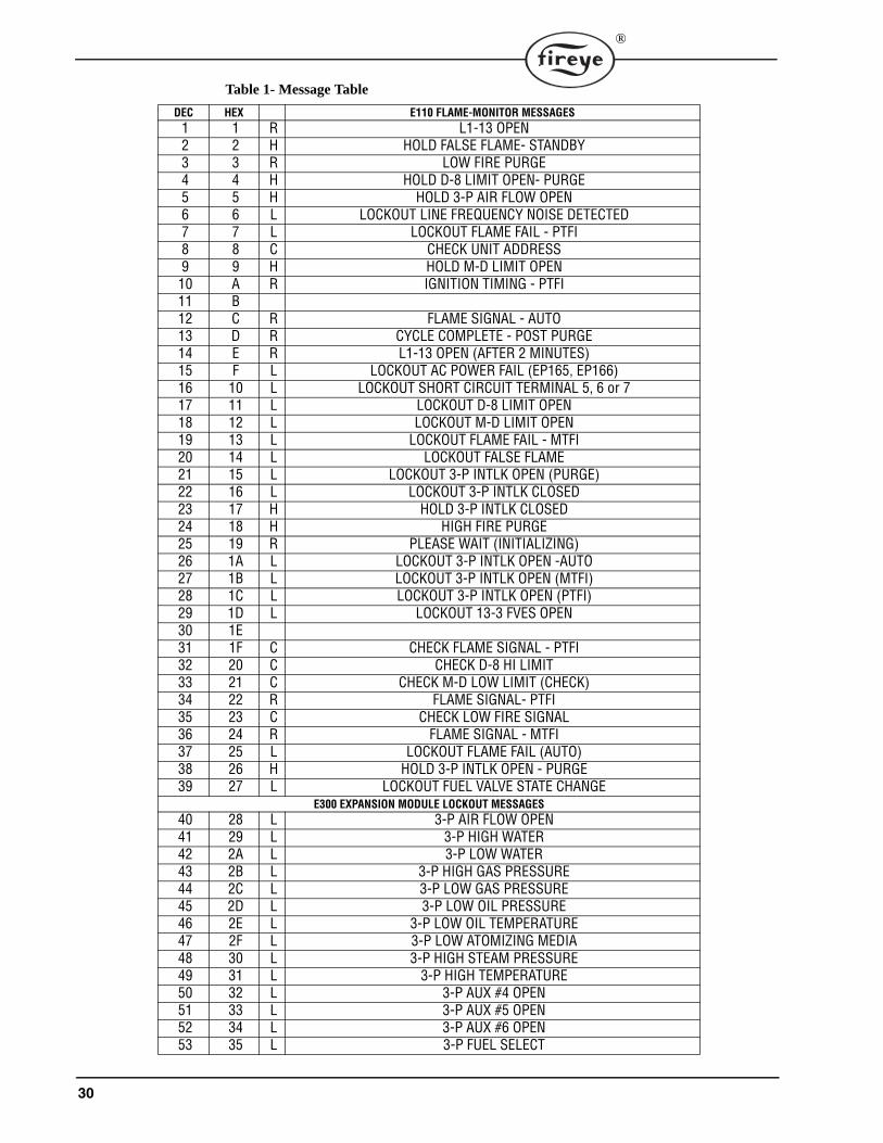
The MSGN being transmitted is a numerical value and must be interpreted by the communicatingdevice, which actually is an advantage since this can be made to be whatever message text the enduser wants. In other words, it allows for programming custom messages without actually changingthe message in the programmer. Refer to Table 1 for message information.
The Flame-Monitor stores its burner on time and system on time (L1 powered) in minutes. For dis-play purposes, the programmer converts this to hours. The information being supplied by Modbuswill be the actual time in minutes and it is up to the communicating device to do the conversion.Since the maximum value stored in the Flame-Monitor is 9,999,999 minutes, the maximum value inhex therefore is 98967FH and comprises two data words. The maximum cycle count is 999,999 dec-imal or F423FH, still two data words. As an example, the System on Minutes data is transmittedfrom the Flame-Monitor to the interface as high word / low word as shown below:
Note: Data from address 9 cannot be accessed directly.
All values are represented in a HEX or base 16 format.
GSTAT determines the type of value TIMER represents. TIMER can be a running timer such as isused in purge, a flame signal or meaningless. Only the lower nibble of GSTAT has any value. If thisvalue is 0 then the TIMER value has no meaning. The value in TIMER is a background minute timerin the Flame-Monitor and should be ignored. If GSTAT is between 4 and 7, the TIMER representsthe current value flame signal. If GSTAT is a 1, 2, or 3 then TIMER represents a running timer value.
41 6 2nd Most Recent Lockout Data
47 6 3rd Most Recent Lockout Data
53 6 4th Most Recent Lockout Data
59 6 5th Most Recent Lockout Data
65 6 6th Most Recent Lockout Data
71 1-3 Input limits and Expansion Module
registers
Returns input limits state and lower and upper expansion module (E300) registers. See Table 3
72 1-2 Expansion Module (E300) registers
Returns lower and upper Expansion Module registers
73 1 Return only upper Expansion Module register
ADDRESS 8 ADDRESS 9
HIGH WORD LOW WORD
HIGH BYTE LOW BYTE HIGH BYTE LOW BYTE
0 98H 97H FH
28
®
The baud rate of the Flame-Monitor is fixed at 4800 bits per second. The format of the data is 8 databits, no parity and 1 stop bit. Due to the RS485 format, the communication format is considered half-duplex. That is, only one user is permitted on the communication lines at a time.
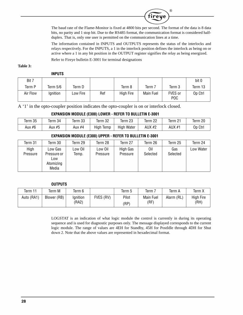
The information contained in INPUTS and OUTPUTS represents the status of the interlocks andrelays respectively. For the INPUTS, a 1 in the interlock position defines the interlock as being on oractive where a 1 in any bit position in the OUTPUT register signifies the relay as being energized.
Refer to Fireye bulletin E-3001 for terminal designations
Table 3:
INPUTS
A ‘1’ in the opto-coupler position indicates the opto-coupler is on or interlock closed.
EXPANSION MODULE (E300) LOWER - REFER TO BULLETIN E-3001
EXPANSION MODULE (E300) UPPER - REFER TO BULLETIN E-3001
OUTPUTS
LOGSTAT is an indication of what logic module the control is currently in during its operatingsequence and is used for diagnostic purposes only. The message displayed corresponds to the currentlogic module. The range of values are 4EH for Standby, 45H for PostIdle through 4DH for Shutdown 2. Note that the above values are represented in hexadecimal format.
Bit 7
Term P Term 5/6 Term D Term 8 Term 7 Term 3
bit 0
Term 13
Air Flow Ignition Low Fire Ref High Fire Main Fuel FVES or POC
Op Ctrl
Term 35 Term 34 Term 33 Term 32 Term 23 Term 22 Term 21 Term 20
Aux #6 Aux #5 Aux #4 High Temp High Water AUX #2 AUX #1 Op Ctrl
Term 31 Term 30 Term 29 Term 28 Term 27 Term 26 Term 25 Term 24
High Pressure
Low Gas Pressure or
Low Atomizing
Media
Low OilTemp.
Low Oil Pressure
High GasPressure
OilSelected
Gas Selected
Low Water
Term 11 Term M Term 6 Term 5 Term 7 Term A Term X
Auto (RA1) Blower (RB) Ignition (RA2)
FVES (RV) Pilot
(RP)
Main Fuel (RF)
Alarm (RL) High Fire (RH)
29
®
Table 2:
EXPLANATION OF LOGSTAT
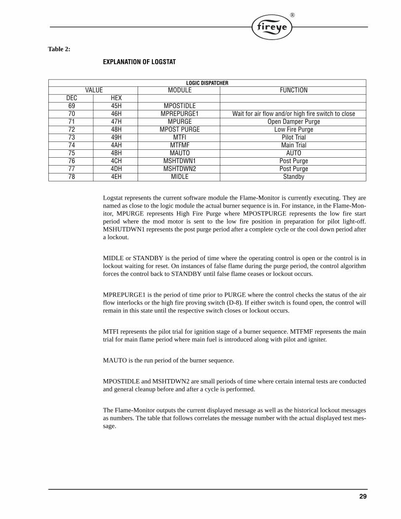
Logstat represents the current software module the Flame-Monitor is currently executing. They arenamed as close to the logic module the actual burner sequence is in. For instance, in the Flame-Mon-itor, MPURGE represents High Fire Purge where MPOSTPURGE represents the low fire startperiod where the mod motor is sent to the low fire position in preparation for pilot light-off.MSHUTDWN1 represents the post purge period after a complete cycle or the cool down period aftera lockout.
MIDLE or STANDBY is the period of time where the operating control is open or the control is inlockout waiting for reset. On instances of false flame during the purge period, the control algorithmforces the control back to STANDBY until false flame ceases or lockout occurs.
MPREPURGE1 is the period of time prior to PURGE where the control checks the status of the airflow interlocks or the high fire proving switch (D-8). If either switch is found open, the control willremain in this state until the respective switch closes or lockout occurs.
MTFI represents the pilot trial for ignition stage of a burner sequence. MTFMF represents the maintrial for main flame period where main fuel is introduced along with pilot and igniter.
MAUTO is the run period of the burner sequence.
MPOSTIDLE and MSHTDWN2 are small periods of time where certain internal tests are conductedand general cleanup before and after a cycle is performed.
The Flame-Monitor outputs the current displayed message as well as the historical lockout messagesas numbers. The table that follows correlates the message number with the actual displayed test mes-sage.
LOGIC DISPATCHERVALUE MODULE FUNCTION
DEC HEX69 45H MPOSTIDLE70 46H MPREPURGE1 Wait for air flow and/or high fire switch to close71 47H MPURGE Open Damper Purge72 48H MPOST PURGE Low Fire Purge73 49H MTFI Pilot Trial74 4AH MTFMF Main Trial75 4BH MAUTO AUTO76 4CH MSHTDWN1 Post Purge77 4DH MSHTDWN2 Post Purge78 4EH MIDLE Standby
30
®
Table 1- Message Table
DEC HEX E110 FLAME-MONITOR MESSAGES1 1 R L1-13 OPEN2 2 H HOLD FALSE FLAME- STANDBY3 3 R LOW FIRE PURGE4 4 H HOLD D-8 LIMIT OPEN- PURGE5 5 H HOLD 3-P AIR FLOW OPEN6 6 L LOCKOUT LINE FREQUENCY NOISE DETECTED7 7 L LOCKOUT FLAME FAIL - PTFI8 8 C CHECK UNIT ADDRESS9 9 H HOLD M-D LIMIT OPEN10 A R IGNITION TIMING - PTFI11 B12 C R FLAME SIGNAL - AUTO13 D R CYCLE COMPLETE - POST PURGE14 E R L1-13 OPEN (AFTER 2 MINUTES)15 F L LOCKOUT AC POWER FAIL (EP165, EP166)16 10 L LOCKOUT SHORT CIRCUIT TERMINAL 5, 6 or 717 11 L LOCKOUT D-8 LIMIT OPEN18 12 L LOCKOUT M-D LIMIT OPEN19 13 L LOCKOUT FLAME FAIL - MTFI20 14 L LOCKOUT FALSE FLAME21 15 L LOCKOUT 3-P INTLK OPEN (PURGE)22 16 L LOCKOUT 3-P INTLK CLOSED23 17 H HOLD 3-P INTLK CLOSED24 18 H HIGH FIRE PURGE25 19 R PLEASE WAIT (INITIALIZING)26 1A L LOCKOUT 3-P INTLK OPEN -AUTO27 1B L LOCKOUT 3-P INTLK OPEN (MTFI)28 1C L LOCKOUT 3-P INTLK OPEN (PTFI)29 1D L LOCKOUT 13-3 FVES OPEN30 1E31 1F C CHECK FLAME SIGNAL - PTFI32 20 C CHECK D-8 HI LIMIT 33 21 C CHECK M-D LOW LIMIT (CHECK)34 22 R FLAME SIGNAL- PTFI35 23 C CHECK LOW FIRE SIGNAL 36 24 R FLAME SIGNAL - MTFI37 25 L LOCKOUT FLAME FAIL (AUTO)38 26 H HOLD 3-P INTLK OPEN - PURGE39 27 L LOCKOUT FUEL VALVE STATE CHANGE
E300 EXPANSION MODULE LOCKOUT MESSAGES40 28 L 3-P AIR FLOW OPEN41 29 L 3-P HIGH WATER42 2A L 3-P LOW WATER43 2B L 3-P HIGH GAS PRESSURE44 2C L 3-P LOW GAS PRESSURE45 2D L 3-P LOW OIL PRESSURE46 2E L 3-P LOW OIL TEMPERATURE47 2F L 3-P LOW ATOMIZING MEDIA48 30 L 3-P HIGH STEAM PRESSURE49 31 L 3-P HIGH TEMPERATURE50 32 L 3-P AUX #4 OPEN51 33 L 3-P AUX #5 OPEN52 34 L 3-P AUX #6 OPEN53 35 L 3-P FUEL SELECT
31
®
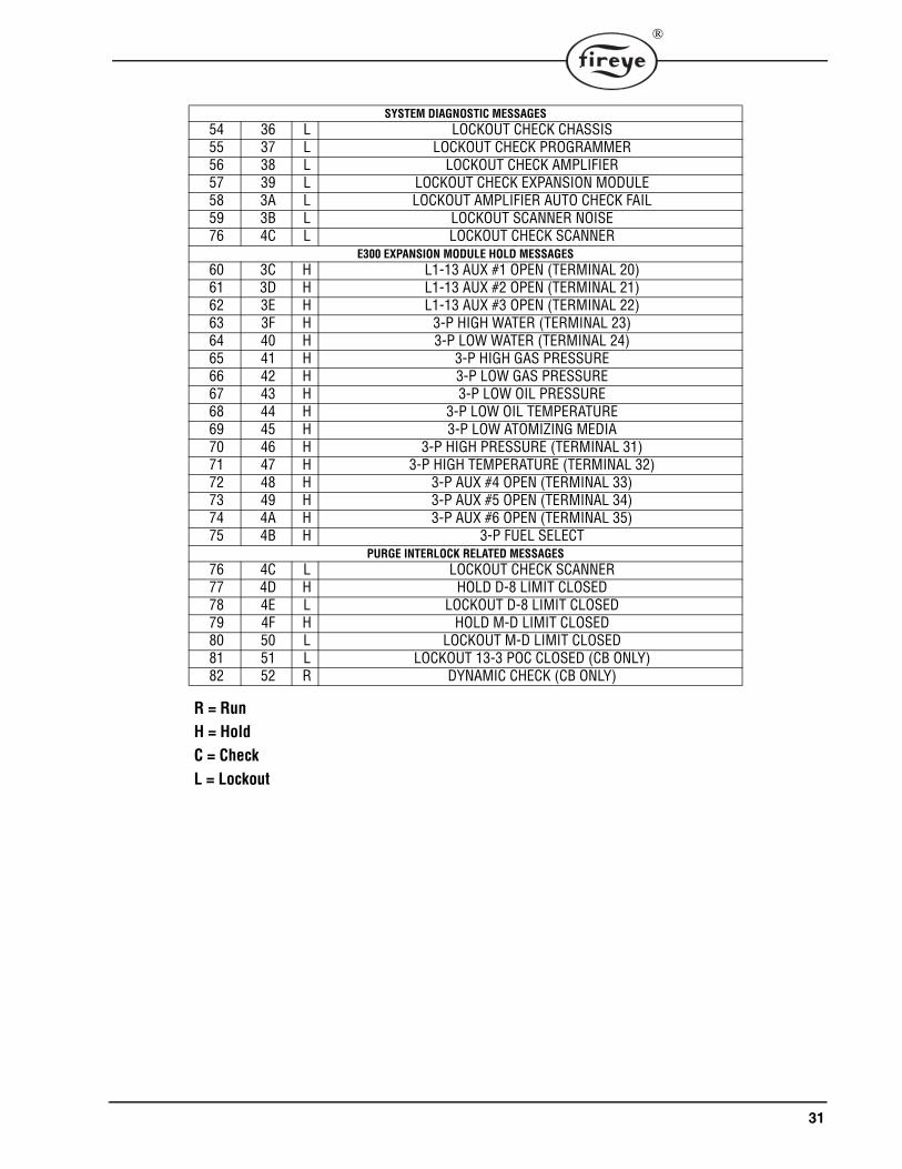
SYSTEM DIAGNOSTIC MESSAGES54 36 L LOCKOUT CHECK CHASSIS55 37 L LOCKOUT CHECK PROGRAMMER56 38 L LOCKOUT CHECK AMPLIFIER57 39 L LOCKOUT CHECK EXPANSION MODULE58 3A L LOCKOUT AMPLIFIER AUTO CHECK FAIL59 3B L LOCKOUT SCANNER NOISE76 4C L LOCKOUT CHECK SCANNER
E300 EXPANSION MODULE HOLD MESSAGES60 3C H L1-13 AUX #1 OPEN (TERMINAL 20)61 3D H L1-13 AUX #2 OPEN (TERMINAL 21)62 3E H L1-13 AUX #3 OPEN (TERMINAL 22)63 3F H 3-P HIGH WATER (TERMINAL 23)64 40 H 3-P LOW WATER (TERMINAL 24)65 41 H 3-P HIGH GAS PRESSURE66 42 H 3-P LOW GAS PRESSURE67 43 H 3-P LOW OIL PRESSURE68 44 H 3-P LOW OIL TEMPERATURE69 45 H 3-P LOW ATOMIZING MEDIA70 46 H 3-P HIGH PRESSURE (TERMINAL 31)71 47 H 3-P HIGH TEMPERATURE (TERMINAL 32)72 48 H 3-P AUX #4 OPEN (TERMINAL 33)73 49 H 3-P AUX #5 OPEN (TERMINAL 34)74 4A H 3-P AUX #6 OPEN (TERMINAL 35)75 4B H 3-P FUEL SELECT
PURGE INTERLOCK RELATED MESSAGES76 4C L LOCKOUT CHECK SCANNER77 4D H HOLD D-8 LIMIT CLOSED78 4E L LOCKOUT D-8 LIMIT CLOSED79 4F H HOLD M-D LIMIT CLOSED80 50 L LOCKOUT M-D LIMIT CLOSED81 51 L LOCKOUT 13-3 POC CLOSED (CB ONLY)82 52 R DYNAMIC CHECK (CB ONLY)
R = RunH = HoldC = CheckL = Lockout
32
®
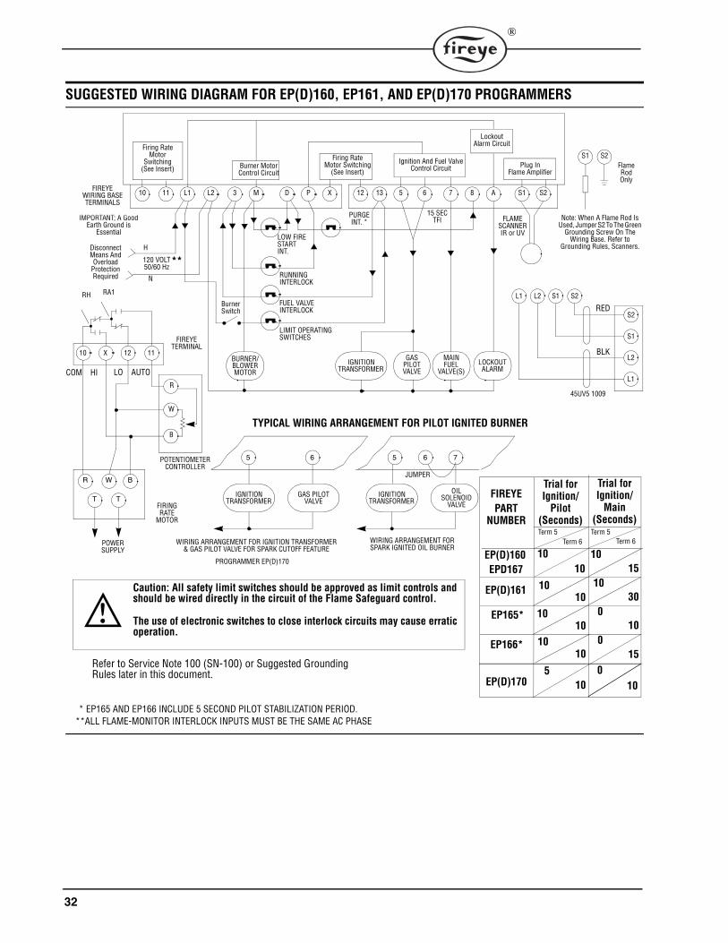
SUGGESTED WIRING DIAGRAM FOR EP(D)160, EP161, AND EP(D)170 PROGRAMMERS
Firing RateMotor
Switching(See Insert) Burner Motor
Control Circuit
Firing RateMotor Switching
(See Insert)Ignition And Fuel Valve
Control Circuit
LockoutAlarm Circuit
Plug InFlame Amplifier
Flame RodOnly
FIREYEWIRING BASETERMINALS
IMPORTANT; A GoodEarth Ground is
Essential
DisconnectMeans AndOverload
ProtectionRequired
120 VOLT50/60 Hz
H
N
Note: When A Flame Rod Is Used, Jumper S2 To The Green
Grounding Screw On The Wiring Base. Refer to
Grounding Rules, Scanners.
15 SECTFI
PURGEINT. * FLAME
SCANNERIR or UVLOW FIRE
STARTINT.
RUNNINGINTERLOCK
FUEL VALVEINTERLOCK
LIMIT OPERATINGSWITCHES
BurnerSwitch RED
Trial forIgnition/
Pilot(Seconds)
Trial forIgnition/
Main(Seconds)
Term 5 Term 5Term 6 Term 6
FIREYEPART
NUMBER
EP(D)16010 15
1010
1030
EP(D)161
EP(D)170
100
15
45UV5 1009
TYPICAL WIRING ARRANGEMENT FOR PILOT IGNITED BURNER
JUMPER
WIRING ARRANGEMENT FORSPARK IGNITED OIL BURNER
WIRING ARRANGEMENT FOR IGNITION TRANSFORMER& GAS PILOT VALVE FOR SPARK CUTOFF FEATURE
Caution: All safety limit switches should be approved as limit controls and should be wired directly in the circuit of the Flame Safeguard control.
The use of electronic switches to close interlock circuits may cause erratic operation.
R
W
B
POWERSUPPLY
FIRINGRATE
MOTOR
POTENTIOMETERCONTROLLER
FIREYETERMINAL
RA1
AUTOLOHICOM
S2S1A87651312XPDM3L2L11110
GAS MAINFUEL
VALVE(S)
L1 L2 S1 S2
S2
S1
L2
L1
PILOTVALVE
LOCKOUTALARM
IGNITIONTRANSFORMER
BURNER/BLOWERMOTOR
R W B
T T
RH
5 6 5 6 7
IGNITIONTRANSFORMER
GAS PILOTVALVE
**
S1 S2
PROGRAMMER EP(D)170
IGNITION OILSOLENOID
VALVETRANSFORMER
10 X 12 11
EP165*10
010
* EP165 AND EP166 INCLUDE 5 SECOND PILOT STABILIZATION PERIOD.
EP166*
Refer to Service Note 100 (SN-100) or Suggested Grounding Rules later in this document.
100
105
10
10
**ALL FLAME-MONITOR INTERLOCK INPUTS MUST BE THE SAME AC PHASE
EPD16710 10
BLK
33
®
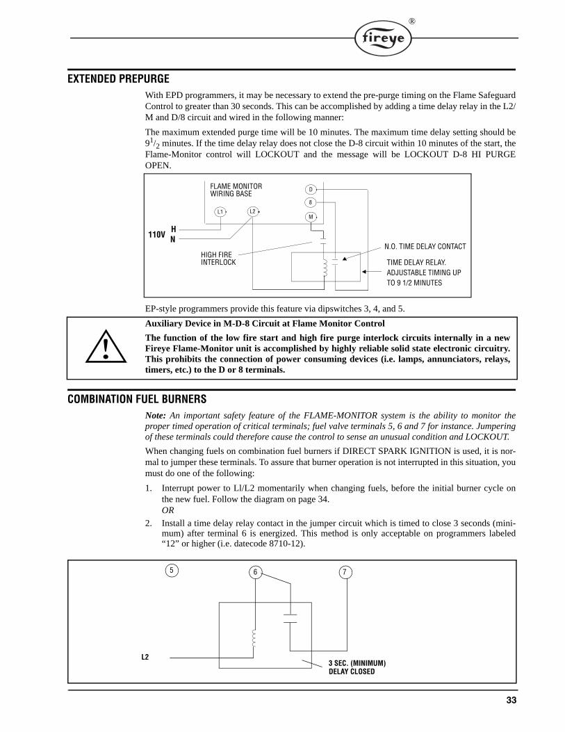
EXTENDED PREPURGEWith EPD programmers, it may be necessary to extend the pre-purge timing on the Flame SafeguardControl to greater than 30 seconds. This can be accomplished by adding a time delay relay in the L2/M and D/8 circuit and wired in the following manner:
The maximum extended purge time will be 10 minutes. The maximum time delay setting should be91/2 minutes. If the time delay relay does not close the D-8 circuit within 10 minutes of the start, theFlame-Monitor control will LOCKOUT and the message will be LOCKOUT D-8 HI PURGEOPEN.
EP-style programmers provide this feature via dipswitches 3, 4, and 5.
Auxiliary Device in M-D-8 Circuit at Flame Monitor Control
The function of the low fire start and high fire purge interlock circuits internally in a newFireye Flame-Monitor unit is accomplished by highly reliable solid state electronic circuitry.This prohibits the connection of power consuming devices (i.e. lamps, annunciators, relays,timers, etc.) to the D or 8 terminals.
COMBINATION FUEL BURNERSNote: An important safety feature of the FLAME-MONITOR system is the ability to monitor theproper timed operation of critical terminals; fuel valve terminals 5, 6 and 7 for instance. Jumperingof these terminals could therefore cause the control to sense an unusual condition and LOCKOUT.
When changing fuels on combination fuel burners if DIRECT SPARK IGNITION is used, it is nor-mal to jumper these terminals. To assure that burner operation is not interrupted in this situation, youmust do one of the following:
1. Interrupt power to Ll/L2 momentarily when changing fuels, before the initial burner cycle onthe new fuel. Follow the diagram on page 34.OR
2. Install a time delay relay contact in the jumper circuit which is timed to close 3 seconds (mini-mum) after terminal 6 is energized. This method is only acceptable on programmers labeled“12” or higher (i.e. datecode 8710-12).
HN110V
HIGH FIREINTERLOCK
N.O. TIME DELAY CONTACT
TIME DELAY RELAY.ADJUSTABLE TIMING UP TO 9 1/2 MINUTES
FLAME MONITORWIRING BASE
L1 L2M
8
D
5 6 7
L23 SEC. (MINIMUM)DELAY CLOSED
34
®
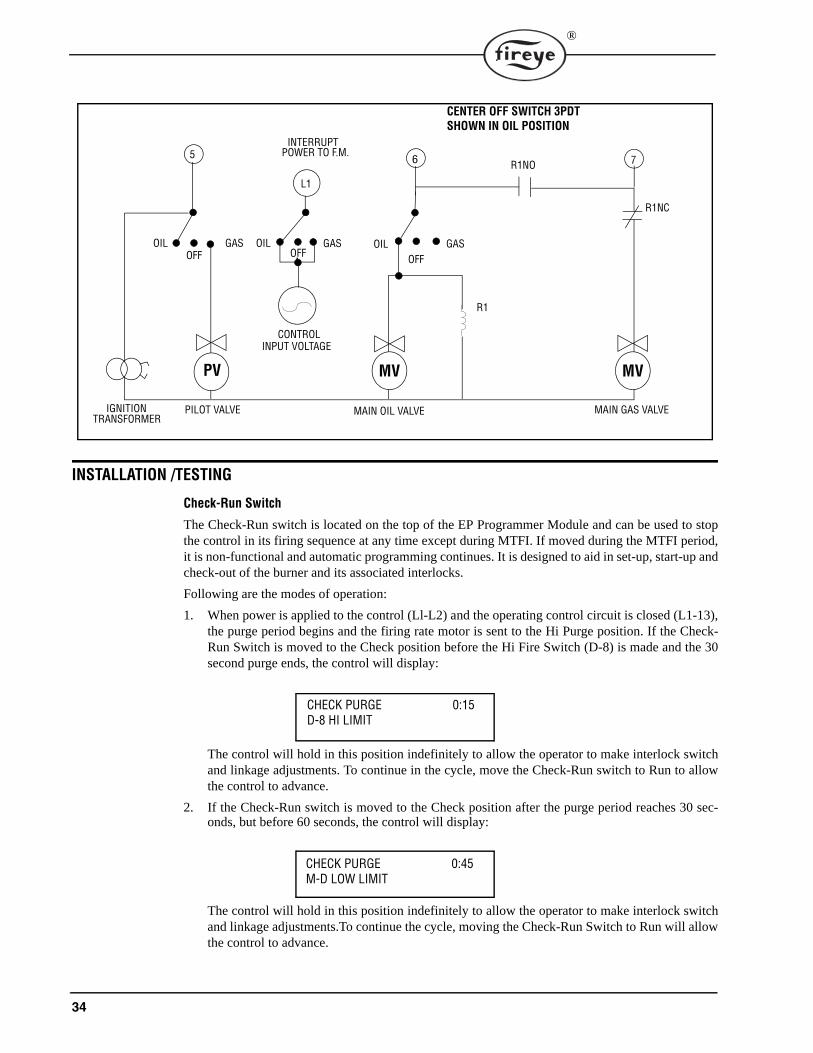
INSTALLATION /TESTING
Check-Run Switch
The Check-Run switch is located on the top of the EP Programmer Module and can be used to stopthe control in its firing sequence at any time except during MTFI. If moved during the MTFI period,it is non-functional and automatic programming continues. It is designed to aid in set-up, start-up andcheck-out of the burner and its associated interlocks.
Following are the modes of operation:
1. When power is applied to the control (Ll-L2) and the operating control circuit is closed (L1-13),the purge period begins and the firing rate motor is sent to the Hi Purge position. If the Check-Run Switch is moved to the Check position before the Hi Fire Switch (D-8) is made and the 30second purge ends, the control will display:
The control will hold in this position indefinitely to allow the operator to make interlock switchand linkage adjustments. To continue in the cycle, move the Check-Run switch to Run to allowthe control to advance.
2. If the Check-Run switch is moved to the Check position after the purge period reaches 30 sec-onds, but before 60 seconds, the control will display:
The control will hold in this position indefinitely to allow the operator to make interlock switchand linkage adjustments.To continue the cycle, moving the Check-Run Switch to Run will allowthe control to advance.
L1
5 6 7
OIL GAS
R1
R1NC
OIL GASOIL
CENTER OFF SWITCH 3PDTSHOWN IN OIL POSITION
INTERRUPT POWER TO F.M.
PV MV
R1NO
MAIN GAS VALVE
MV
MAIN OIL VALVEPILOT VALVEIGNITIONTRANSFORMER
OFF OFF
CONTROLINPUT VOLTAGE
GASOFF
CHECK PURGE 0:15D-8 HI LIMIT
CHECK PURGE 0:45M-D LOW LIMIT
35
®
3. After the PTFI period has begun, switching back to the Check position will stop the program in thePTFI period, allowing for pilot and/or scanner alignment adjustments to be made. The control willdisplay:
It will hold in this position indefinitely as long as the flame signal strength is above the thresholdof 10. If it drops below 10 for thirty consecutive seconds, lockout will occur and the message onthe display will read Flame Fail PTFI.
4. Switching from run to check during the burner on period will drive the modulator circuit to lowfire (10-12 Closes). This allows for low fire fuel-air adjustments and holding the burner at low fire.Consult your boiler/burner instructions for low fire hold firing recommendations. The control willdisplay:
As an aid adjusting the burner linkages, pilot, etc., a check-run selector is provided on each EP-andEPD Series Programmer Module.
OPERATIONAL TESTWARNING: Before testing the control operation on the boiler, close the manual main shut-offfuel valve. Failure to do this may cause injury or property damage.
1. Close the manual main shut-off fuel valve.
2. Recheck all limit circuit wiring for proper operation and correct connection.3. Confirm that the automatic main fuel valves are wired to terminal “7.”4. Power the control and electronically check the proper sequence of operation according to the
Operation section on page 11 of this bulletin.5. After assuring yourself that all interlocks and valves are properly wired and that the sequence of
operation is correct, open the manual main shut-off fuel valve and proceed cautiously through theboiler light off process. Check all safety interlocks for proper shut down of the boiler.
When the installation and all burner adjustments are completed, the entire burner control system shouldbe tested in accordance with the burner manufacturer’s instructions. The procedure should verify thecorrect operation of:
1. Each operating control (temperature, pressure, etc.).
2. Each limit switch (temperature, pressure, low water cutoff, etc.).3. Each interlock switch (airflow switch, high and low fuel pressure or temperature switches, purge
and low fire start switches, fuel valve proof of closure interlock, etc.).4. Pilot flame failure response and lockout.5. Main flame failure response and lockout.6. Tight shut off of all fuel valves.
CAUTION: LIVE VOLTAGE IS NECESSARY TO PERFORM THIS TEST.
Voltage Test
A Voltage Check is necessary to identify a potential problem with the supply to the control. This couldbe caused by an improperly sized or faulty transformer, faulty load coils or low entry voltage. Followthis procedure:
1. Using the Service Adapter (60-2107), monitor the L1-L2 supply throughout a complete burnercycle. The acceptable voltage range is 102V-132V. At no time during the cycle should the voltagedip below the minimum level.
2. Check other load terminal (M/L2, 5/L2, 6/L2, 7/L2) for voltage at improper times or improper val-ues.
CHECK PTFI 19FLAME SIGNAL
CHECK AUTO 25LOW FIRE SIGNAL
36
®
TEST CHECKOUT PROCEDURESNormal Pilot Flame Test
CAUTION: Before making a pilot flame test, manually shut off the fuel supply to the mainburner.
1. At the start of PTFI, place the Check-run switch in the check position.
2. Observe the pilot flame signal on the display. If the average signal is below the minimum of 10,readjust the pilot flame or realign the flame detector.
3. During the pilot flame test, if flame is not detected for a continuous 30 seconds, the control willlockout. To re-establish the pilot flame trial for ignition (PTFI), manual reset of the lockout switchis required, and a complete prepurge accomplished.
4. When UV flame detection is used, a test is required to verify that UV radiation from the ignitionspark is not being detected. To accomplish this, manually shut off both pilot and main fuels. Initiatea normal start-up, and when the PTFI display comes on, observe the display which should read nosignal more than 4. If more than 4 is observed, realign the UV scanner, and/or shield the spark fromthe scanner’s view.
5. With all methods of flame detection, check pilot flame failure response by manually shutting off thepilot fuel and then initiate a normal start-up. With no pilot flame present, the control will de- ener-gize the pilot assembly at the end of the trial for ignition interval, and the control will lockout. Alsocheck to verify that the ignition spark does not “give” a flame signal on infrared or flame rod appli-cations.
Main Flame Test
NOTE: This test requires an interrupted pilot (a pilot that shuts off after main flame has been estab-lished.1. Proceed through a normal startup. After the pilot flame is shut off, observe the reading on the dis-
play. If the signal reading is low, readjust main flame or realign detector.
2. Check main flame failure protection by manually shutting off the main fuel supply. Within 4 sec-onds after main flame goes out, the fuel valve will be de-energized. The alarm circuit will be ener-gized following safety lockout.
Minimum Pilot Test
CAUTION: The minimum pilot test must be accomplished by a trained and qualified burnertechnician.
This test assures that the flame detector will not detect a pilot flame too small to reliably light off themain flame. The test should be made on every new installation and following any reapportioning of theflame detector. This procedure should not be used on a direct spark ignited burner.
1. Turn off the main fuel supply manually.
2. At the start of PTFI, place the Check-run switch in the check position.3. Reduce the fuel supply to the pilot until the display reads below 10.4. Slowly increase the fuel to the pilot until the display reads 10. This is minimum pilot flame that the
flame detector will reliably detect.5. Place the Check-run switch in the Run position. When the main fuel safety shut-off valve is ener-
gized, slowly open the manual main fuel valve.6. Observe the light-off of the main flame. It must be smooth and normal.
CAUTION: If the main flame does not ignite immediately, shut off the main fuel. Realign thedetector to require larger minimum pilot flame.
7. Repeat the test until a reliable and smooth light-off occurs with the minimum pilot.8. After this test is completed, increase the fuel to the pilot to its normal setting.
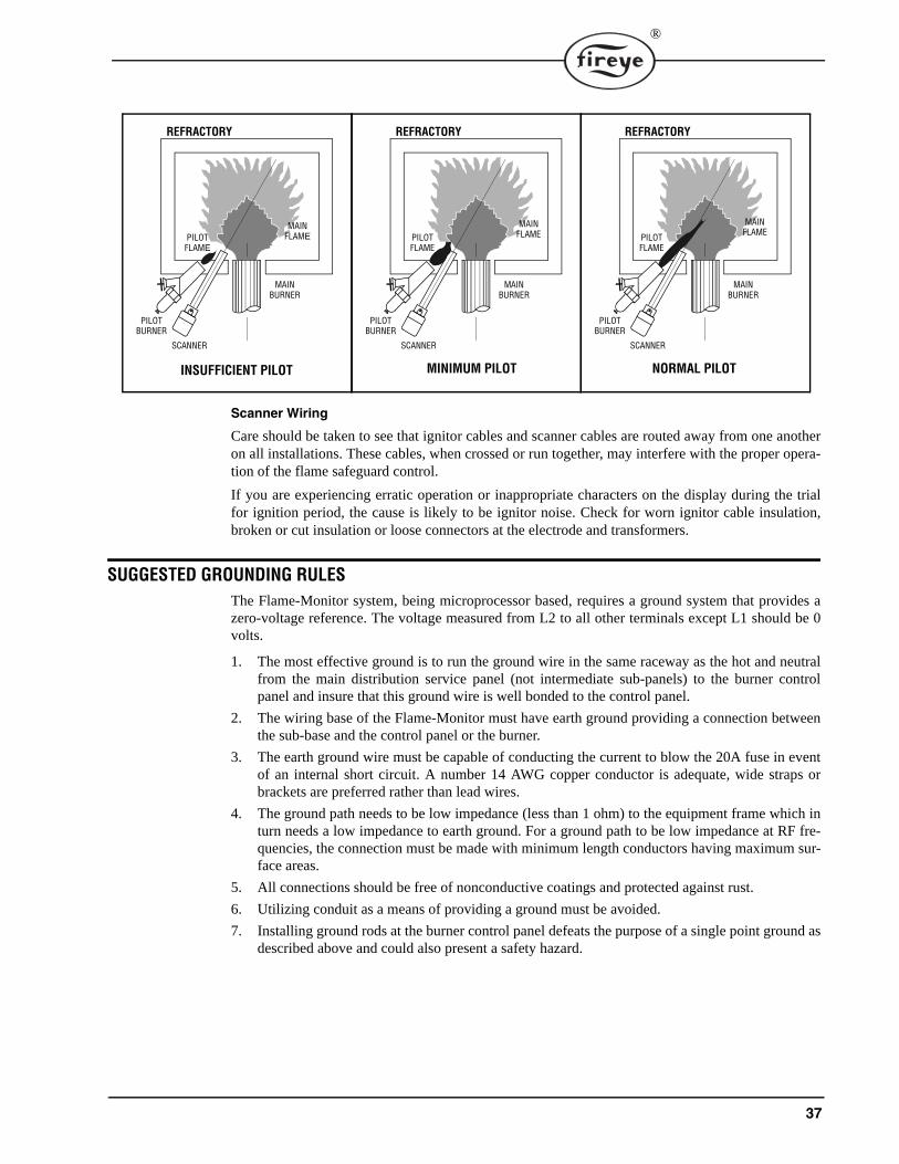
37
®
Scanner Wiring
Care should be taken to see that ignitor cables and scanner cables are routed away from one anotheron all installations. These cables, when crossed or run together, may interfere with the proper opera-tion of the flame safeguard control.
If you are experiencing erratic operation or inappropriate characters on the display during the trialfor ignition period, the cause is likely to be ignitor noise. Check for worn ignitor cable insulation,broken or cut insulation or loose connectors at the electrode and transformers.
SUGGESTED GROUNDING RULESThe Flame-Monitor system, being microprocessor based, requires a ground system that provides azero-voltage reference. The voltage measured from L2 to all other terminals except L1 should be 0volts.
1. The most effective ground is to run the ground wire in the same raceway as the hot and neutralfrom the main distribution service panel (not intermediate sub-panels) to the burner controlpanel and insure that this ground wire is well bonded to the control panel.
2. The wiring base of the Flame-Monitor must have earth ground providing a connection betweenthe sub-base and the control panel or the burner.
3. The earth ground wire must be capable of conducting the current to blow the 20A fuse in eventof an internal short circuit. A number 14 AWG copper conductor is adequate, wide straps orbrackets are preferred rather than lead wires.
4. The ground path needs to be low impedance (less than 1 ohm) to the equipment frame which inturn needs a low impedance to earth ground. For a ground path to be low impedance at RF fre-quencies, the connection must be made with minimum length conductors having maximum sur-face areas.
5. All connections should be free of nonconductive coatings and protected against rust.
6. Utilizing conduit as a means of providing a ground must be avoided.
7. Installing ground rods at the burner control panel defeats the purpose of a single point ground asdescribed above and could also present a safety hazard.
MAINFLAME
REFRACTORY
MAINBURNER
PILOTFLAME
SCANNER
PILOTBURNER
INSUFFICIENT PILOT
MAINFLAME
REFRACTORY
MAINBURNER
PILOTFLAME
SCANNER
PILOTBURNER
MINIMUM PILOT
MAINFLAME
REFRACTORY
MAINBURNER
PILOTFLAME
SCANNER
PILOTBURNER
NORMAL PILOT
38
®
INSTALLATIONDo not run high voltage ignition transformer wires in the same conduit with flame detection wiring.
Do not run scanner wires in a conduit with line voltage circuits.
Ensure the frame of the ignition transformer is securely connected to control panel frame or prefera-bly the burner frame.
The Flame-Monitor chassis (EB700) contains a transient suppressing device connected internallyacross hot and neutral and then to the internal bracket. For this to be effective the chassis must bescrewed securely into the wiring subbase.
REMOTE DISPLAYWhen the ED510 is to be remotely mounted on the front of the control panel, the ED580 cable mustcontain a ferrite core, currently supplied by Fireye with the cable. High frequency currents flow moreto the surface of the conductor. The 60 Hz ground system, properly designed, has sufficient low-impedance at 60 Hz to maintain all metal surfaces at the same ground reference. But, this same sys-tem is unable to provide this at higher frequencies, because of the increased impedance caused by the‘skin effect’. The purpose of the ferrite core is to provide a low-impedance at these higher frequen-cies and absorb this unwanted energy.
Care must be taken not to route the ED580 cable in close proximity to any starter motor contactorslocated in the control panel or across any high voltage ignition wires. Refer to Fireye bulletin E-8002for proper installation.
COMMUNICATIONSWhen interfacing Fireye controls to a communication system, be it an E500, PLC or other micropro-cessor based device, ferrite cores should also be utilized. Proper twisted shielded pair cable must beutilized. In a multi-drop system, the shields should be tied together within a cabinet and not to anyground point. The shield at the source end of the cable of the multi-drop connection can then be ter-minated to ground. Source end is defined as the originating end of the communication system
Care must be taken not to route communication cables in close proximity to any starter motor contac-tors located in the control panel or across any high voltage ignition wires. Refer to Fireye bulletin E-8002 for proper installation.
SCANNERSThe armored cable supplied with the Ultra-Violet and Infrared scanners should be connected toequipment by means of a good mechanical connection such as a conduit fitting. It may be necessaryto utilize heat insulator (P/N 35-69) to isolate the sensing end of the scanner from boiler ground.Care must be taken not to route the scanner cable across the high voltage ignition cable. The highenergy ignition cable should be checked periodically for cracking, connections and aging.
In applications using flame rod units and the ERT1 amplifier, it may be beneficial to route a separatereturn wire from the S2 terminal to the flame rod assembly. This will minimize the effects of tran-sient currents flowing into the Flame-Monitor.
In all cases, scanner wires should be routed in separate conduit and not joined with any high voltageAC or ignition cables.
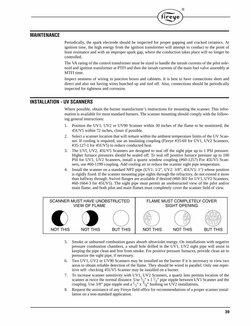
39
®
MAINTENANCEPeriodically, the spark electrode should be inspected for proper gapping and cracked ceramics. Atignition time, the high energy from the ignition transformer will attempt to conduct to the point ofleast resistance and with an improper spark gap, where the conduction takes place will no longer becontrolled.
The VA rating of the control transformer must be sized to handle the inrush currents of the pilot sole-noid and ignition transformer at PTFI and then the inrush currents of the main fuel valve assembly atMTFI time.
Inspect neatness of wiring in junction boxes and cabinets. It is best to have connections short anddirect and also not having wires bunched up and tied off. Also, connections should be periodicallyinspected for tightness and corrosion.
INSTALLATION - UV SCANNERSWhere possible, obtain the burner manufacturer’s instructions for mounting the scanner. This infor-mation is available for most standard burners. The scanner mounting should comply with the follow-ing general instructions:
1. Position the UV1, UV2 or UV90 Scanner within 30 inches of the flame to be monitored; the45UV5 within 72 inches, closer if possible.
2. Select a scanner location that will remain within the ambient temperature limits of the UV Scan-ner. If cooling is required, use an insulating coupling (Fireye #35-69 for UV1, UV2 Scanners,#35-127-1 for 45UV5) to reduce conducted heat.
3. The UVl, UV2, 45UV5 Scanners are designed to seal off the sight pipe up to 1 PSI pressure.Higher furnace pressures should be sealed off. To seal off positive furnace pressure up to 100PSI for UV1, UV2 Scanners, install a quartz window coupling (#60-1257) For 45UV5 Scan-ners, use #60-1199 coupling. Add cooling air to reduce the scanner sight pipe temperature.
4. Install the scanner on a standard NPT pipe (UV1: 1/2", UV2: 3/8”, 45UV5: 1") whose positionis rigidly fixed. If the scanner mounting pipe sights through the refractory, do not extend it morethan halfway through. Swivel flanges are available if desired (#60-302 for UV1, UV2 Scanners,#60-1664-3 for 45UV5). The sight pipe must permit an unobstructed view of the pilot and/ormain flame, and both pilot and main flames must completely cover the scanner field of view.
5. Smoke or unburned combustion gases absorb ultraviolet energy. On installations with negativepressure combustion chambers, a small hole drilled in the UV1, UV2 sight pipe will assist inkeeping the pipe clean and free from smoke. For positive pressure furnaces, provide clean air topressurize the sight pipe, if necessary.
6. Two UV1, UV2 or UV90 Scanners may be installed on the burner if it is necessary to view twoareas to obtain reliable detection of the flame. They should be wired in parallel. Only one repet-itive self- checking 45UV5 Scanner may be installed on a burner.
7. To increase scanner sensitivity with UV1, UV2 Scanners, a quartz lens permits location of thescanner at twice the normal distance. Use l/2” x 1 l/2” pipe nipple between UV1 Scanner and thecoupling. Use 3/8” pipe nipple and a l/2” x 3/8” bushing on UV2 installations.
8. Request the assistance of any Fireye field office for recommendations of a proper scanner instal-lation on a non-standard application.
SCANNER MUST HAVE UNOBSTRUCTEDVIEW OF FLAME
NOT THIS NOT THIS BUT THIS
FLAME MUST COMPLETELY COVERSIGHT OPENING
NOT THIS NOT THIS BUT THIS
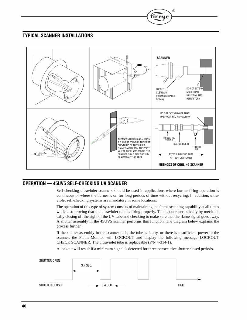
40
®
TYPICAL SCANNER INSTALLATIONS
OPERATION — 45UV5 SELF-CHECKING UV SCANNERSelf-checking ultraviolet scanners should be used in applications where burner firing operation iscontinuous or where the burner is on for long periods of time without recycling. In addition, ultra-violet self-checking systems are mandatory in some locations.
The operation of this type of system consists of maintaining the flame scanning capability at all timeswhile also proving that the ultraviolet tube is firing properly. This is done periodically by mechani-cally closing off the sight of the UV tube and checking to make sure that the flame signal goes away.A shutter assembly in the 45UV5 scanner performs this function. The diagram below explains theprocess further.
If the shutter assembly in the scanner fails, the tube is faulty, or there is insufficient power to thescanner, the Flame-Monitor will LOCKOUT and display the following message LOCKOUTCHECK SCANNER. The ultraviolet tube is replaceable (P/N 4-314-1).
A lockout will result if a minimum signal is detected for three consecutive shutter closed periods.
THE MAXIMUM UV SIGNAL FROM A FLAME IS FOUND IN THE FIRST ONE-THIRD OF THE VISIBLE FLAME TAKEN FROM THE POINT WHERE THE FLAME BEGINS. THE SCANNER SIGHT PIPE SHOULD BE AIMED AT THIS AREA.
DO NOT EXTENDMORE THANHALF-WAY INTOREFRACTORY
SCANNER
FORCEDCLEAN AIR(FROM DISCHARGEOF FAN)
METHODS OF COOLING SCANNER
INSULATINGTUBING
SEALING UNIONFORCED
AIR
EXTEND SIGHTING TUBE6”(1524) OR 8”(2032)
DO NOT EXTEND MORE THANHALF-WAY INTO REFRACTORY
SHUTTER OPEN
SHUTTER CLOSED
3.7 SEC.
0.4 SEC. TIME
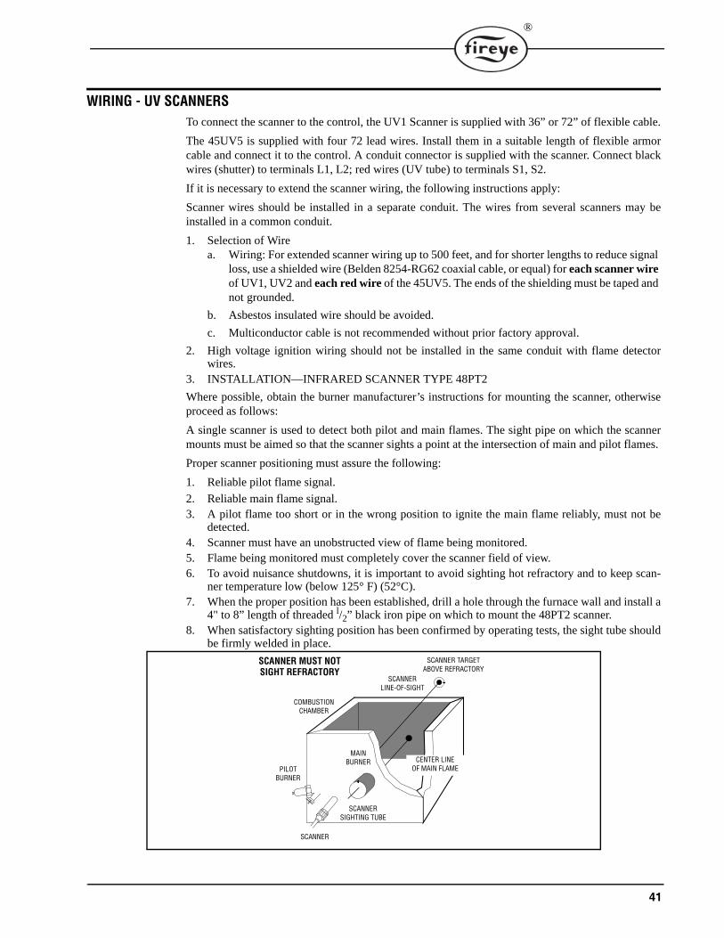
41
®
WIRING - UV SCANNERSTo connect the scanner to the control, the UV1 Scanner is supplied with 36” or 72” of flexible cable.
The 45UV5 is supplied with four 72 lead wires. Install them in a suitable length of flexible armorcable and connect it to the control. A conduit connector is supplied with the scanner. Connect blackwires (shutter) to terminals L1, L2; red wires (UV tube) to terminals S1, S2.
If it is necessary to extend the scanner wiring, the following instructions apply:
Scanner wires should be installed in a separate conduit. The wires from several scanners may beinstalled in a common conduit.
1. Selection of Wirea. Wiring: For extended scanner wiring up to 500 feet, and for shorter lengths to reduce signal
loss, use a shielded wire (Belden 8254-RG62 coaxial cable, or equal) for each scanner wire of UV1, UV2 and each red wire of the 45UV5. The ends of the shielding must be taped and not grounded.
b. Asbestos insulated wire should be avoided.
c. Multiconductor cable is not recommended without prior factory approval.
2. High voltage ignition wiring should not be installed in the same conduit with flame detectorwires.
3. INSTALLATION—INFRARED SCANNER TYPE 48PT2
Where possible, obtain the burner manufacturer’s instructions for mounting the scanner, otherwiseproceed as follows:
A single scanner is used to detect both pilot and main flames. The sight pipe on which the scannermounts must be aimed so that the scanner sights a point at the intersection of main and pilot flames.
Proper scanner positioning must assure the following:
1. Reliable pilot flame signal.
2. Reliable main flame signal.3. A pilot flame too short or in the wrong position to ignite the main flame reliably, must not be
detected.4. Scanner must have an unobstructed view of flame being monitored.5. Flame being monitored must completely cover the scanner field of view.6. To avoid nuisance shutdowns, it is important to avoid sighting hot refractory and to keep scan-
ner temperature low (below 125° F) (52°C).7. When the proper position has been established, drill a hole through the furnace wall and install a
4" to 8” length of threaded l/2” black iron pipe on which to mount the 48PT2 scanner.8. When satisfactory sighting position has been confirmed by operating tests, the sight tube should
be firmly welded in place.
CENTER LINEOF MAIN FLAME
SCANNERLINE-OF-SIGHT
SCANNER TARGETABOVE REFRACTORY
COMBUSTIONCHAMBER
PILOTBURNER
SCANNER
SCANNERSIGHTING TUBE
MAINBURNER
SCANNER MUST NOTSIGHT REFRACTORY
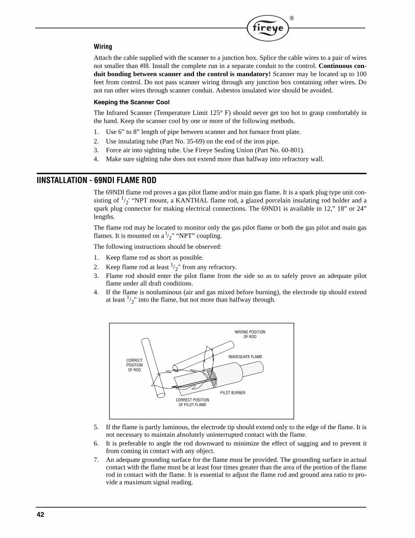
42
®
Wiring
Attach the cable supplied with the scanner to a junction box. Splice the cable wires to a pair of wiresnot smaller than #l8. Install the complete run in a separate conduit to the control. Continuous con-duit bonding between scanner and the control is mandatory! Scanner may be located up to 100feet from control. Do not pass scanner wiring through any junction box containing other wires. Donot run other wires through scanner conduit. Asbestos insulated wire should be avoided.
Keeping the Scanner Cool
The Infrared Scanner (Temperature Limit 125° F) should never get too hot to grasp comfortably inthe hand. Keep the scanner cool by one or more of the following methods.
1. Use 6” to 8” length of pipe between scanner and hot furnace front plate.
2. Use insulating tube (Part No. 35-69) on the end of the iron pipe.3. Force air into sighting tube. Use Fireye Sealing Union (Part No. 60-801).4. Make sure sighting tube does not extend more than halfway into refractory wall.
IINSTALLATION - 69NDl FLAME RODThe 69NDl flame rod proves a gas pilot flame and/or main gas flame. It is a spark plug type unit con-sisting of 1/2' “NPT mount, a KANTHAL flame rod, a glazed porcelain insulating rod holder and aspark plug connector for making electrical connections. The 69ND1 is available in 12,” 18” or 24”lengths.
The flame rod may be located to monitor only the gas pilot flame or both the gas pilot and main gasflames. It is mounted on a l/2" “NPT” coupling.
The following instructions should be observed:
1. Keep flame rod as short as possible.
2. Keep flame rod at least 1/2" from any refractory.3. Flame rod should enter the pilot flame from the side so as to safely prove an adequate pilot
flame under all draft conditions.4. If the flame is nonluminous (air and gas mixed before burning), the electrode tip should extend
at least 1/2" into the flame, but not more than halfway through.
5. If the flame is partly luminous, the electrode tip should extend only to the edge of the flame. It isnot necessary to maintain absolutely uninterrupted contact with the flame.
6. It is preferable to angle the rod downward to minimize the effect of sagging and to prevent itfrom coming in contact with any object.
7. An adequate grounding surface for the flame must be provided. The grounding surface in actualcontact with the flame must be at least four times greater than the area of the portion of the flamerod in contact with the flame. It is essential to adjust the flame rod and ground area ratio to pro-vide a maximum signal reading.
WRONG POSITIONOF ROD
INADEQUATE FLAME
PILOT BURNER
CORRECT POSITIONOF PILOT FLAME
CORRECTPOSITIONOF ROD
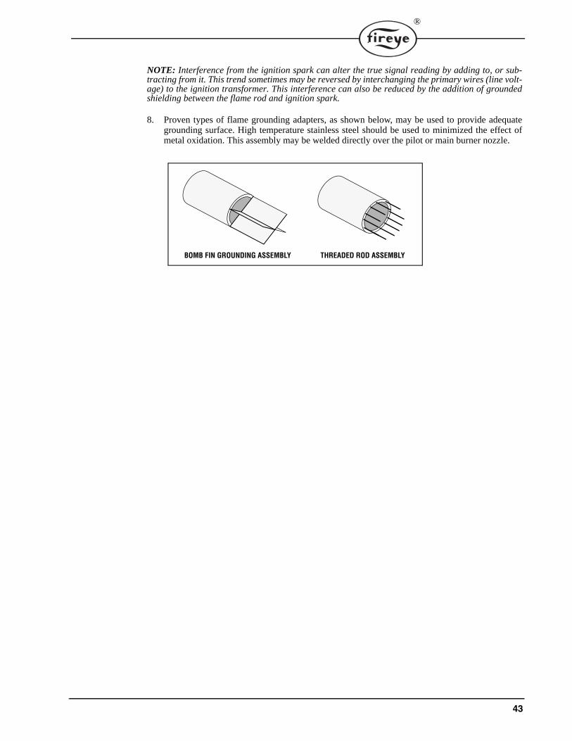
43
®
NOTE: Interference from the ignition spark can alter the true signal reading by adding to, or sub-tracting from it. This trend sometimes may be reversed by interchanging the primary wires (line volt-age) to the ignition transformer. This interference can also be reduced by the addition of groundedshielding between the flame rod and ignition spark.
8. Proven types of flame grounding adapters, as shown below, may be used to provide adequategrounding surface. High temperature stainless steel should be used to minimized the effect ofmetal oxidation. This assembly may be welded directly over the pilot or main burner nozzle.
BOMB FIN GROUNDING ASSEMBLY THREADED ROD ASSEMBLY
44
®
MAINTENANCE
Infrared and Ultraviolet Scanners
The viewing area of the scanner must be kept clean. Even a small amount of contamination willreduce the flame signal reaching the detector by a measurable amount. Wipe the viewing area rou-tinely using a soft cloth dampened with concentrated detergent.
— Type 48PT2 Scanners include a replaceable #4-263-1 Firetron cell.
— Type 45UV5 Scanners include a replaceable #4-314-1 UV tube.
Type 69ND1 Flame Rod
The flame rod and its insulator should be kept clean by washing routinely with soap and water. Rodsshould be routinely replaced as they oxidize.
Flame Signal Strength
Routine observation of the flame signal strength will forewarn any deterioration in the capability ofthe flame detector or its application.
Contacts
There are no accessible contacts in the Flame-Monitor. Where contacts are used, their design assureslong trouble-free life when the load circuits are maintained within the published load ratings.
Electrical Noise
In areas of excessive electrical noise, the installation of an electrical noise suppressor to the powersupply at the control circuit may be helpful.
Humidity
In areas of high humidity, the control chassis should be removed and placed in a dry atmospherewhen the system is expected to be out of service for an extended period.
Periodic Safety Check
It is recommended that a procedure be established to test the complete flame safeguard system atleast once a month. This test should verify the proper operation of all limit switches and safety inter-locks as well as flame failure protection and fuel safety shutoff valve tightness.
Rotation
It is recommended that control and scanner units purchased as spares be installed periodically toensure proper operation.
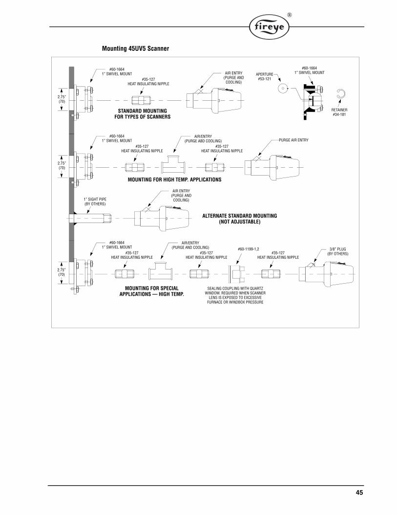
45
®
Mounting 45UV5 Scanner
2.75”(70)
#60-16641” SWIVEL MOUNT
#35-127HEAT INSULATING NIPPLE
STANDARD MOUNTINGFOR TYPES OF SCANNERS
AIR ENTRY(PURGE AND
COOLING)
#60-16641” SWIVEL MOUNT
#35-127HEAT INSULATING NIPPLE
MOUNTING FOR HIGH TEMP. APPLICATIONS
PURGE AIR ENTRYAIR/ENTRY
(PURGE ABD COOLING)#35-127
HEAT INSULATING NIPPLE
1” SIGHT PIPE(BY OTHERS)
AIR ENTRY(PURGE AND
COOLING)
ALTERNATE STANDARD MOUNTING(NOT ADJUSTABLE)
#60-16641” SWIVEL MOUNT
#35-127HEAT INSULATING NIPPLE
MOUNTING FOR SPECIALAPPLICATIONS — HIGH TEMP.
3/8” PLUG(BY OTHERS)
AIR/ENTRY(PURGE AND COOLING)
#35-127HEAT INSULATING NIPPLE
#35-127HEAT INSULATING NIPPLE
#60-1199-1,2
SEALING COUPLING WITH QUARTZWINDOW. REQUIRED WHEN SCANNER
LENS IS EXPOSED TO EXCESSIVEFURNACE OR WINDBOX PRESSURE
APERTURE#53-121
#60-16641” SWIVEL MOUNT
RETAINER#34-181
2.75”(70)
2.75”(70)
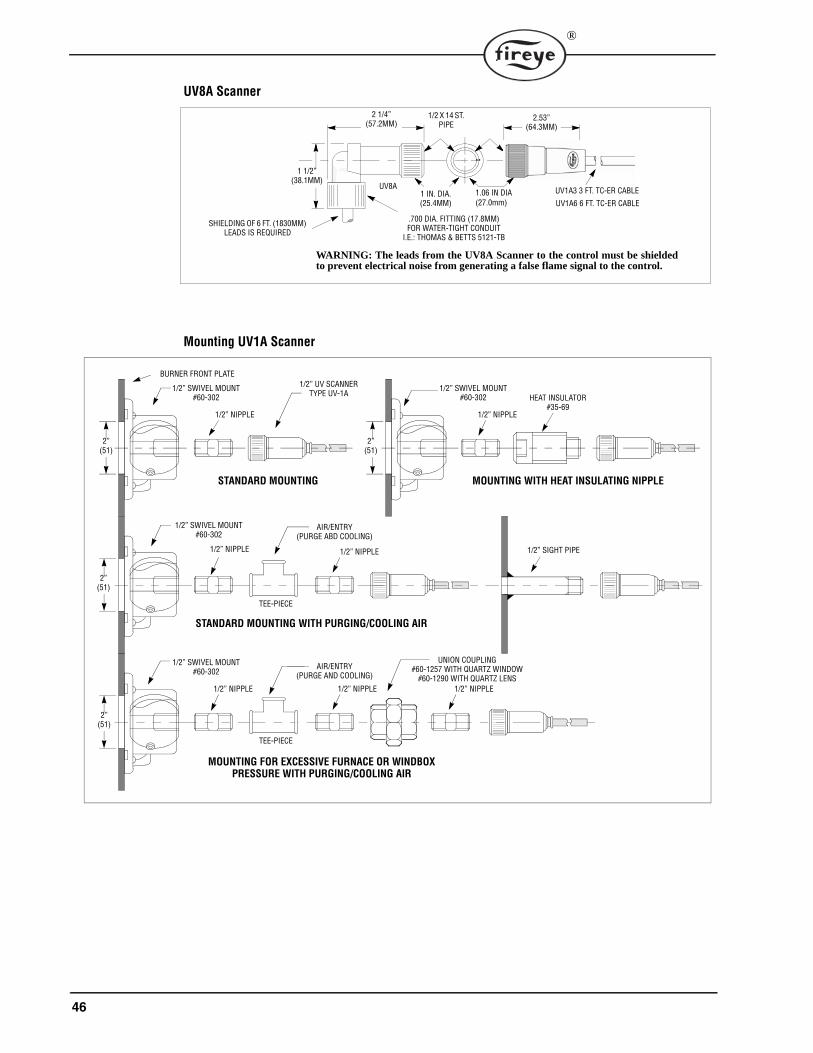
46
®
UV8A Scanner
Mounting UV1A Scanner
2 1/4”(57.2MM)
UV1A3 3 FT. TC-ER CABLE
UV1A6 6 FT. TC-ER CABLE
1 1/2”(38.1MM)
UV8A
1/2 X 14 ST.PIPE
1 IN. DIA.(25.4MM)
2.53”(64.3MM)
SHIELDING OF 6 FT. (1830MM)LEADS IS REQUIRED
.700 DIA. FITTING (17.8MM)FOR WATER-TIGHT CONDUIT
I.E.: THOMAS & BETTS 5121-TB
WARNING: The leads from the UV8A Scanner to the control must be shieldedto prevent electrical noise from generating a false flame signal to the control.
1.06 IN DIA(27.0mm)
UNION COUPLING#60-1257 WITH QUARTZ WINDOW
#60-1290 WITH QUARTZ LENS
2”(51)
1/2” NIPPLE
HEAT INSULATOR#35-69
1/2” SWIVEL MOUNT#60-302
MOUNTING WITH HEAT INSULATING NIPPLE
1/2” NIPPLE
1/2” SWIVEL MOUNT#60-302
STANDARD MOUNTING
BURNER FRONT PLATE1/2” UV SCANNER
TYPE UV-1A
1/2” SWIVEL MOUNT#60-302
STANDARD MOUNTING WITH PURGING/COOLING AIR
1/2” NIPPLE
TEE-PIECE
1/2” NIPPLE
1/2” SWIVEL MOUNT#60-302
MOUNTING FOR EXCESSIVE FURNACE OR WINDBOXPRESSURE WITH PURGING/COOLING AIR
1/2” NIPPLE
TEE-PIECE
1/2” NIPPLE
AIR/ENTRY(PURGE ABD COOLING)
1/2” SIGHT PIPE
AIR/ENTRY(PURGE AND COOLING)
2”(51)
2”(51)
2”(51)
1/2” NIPPLE
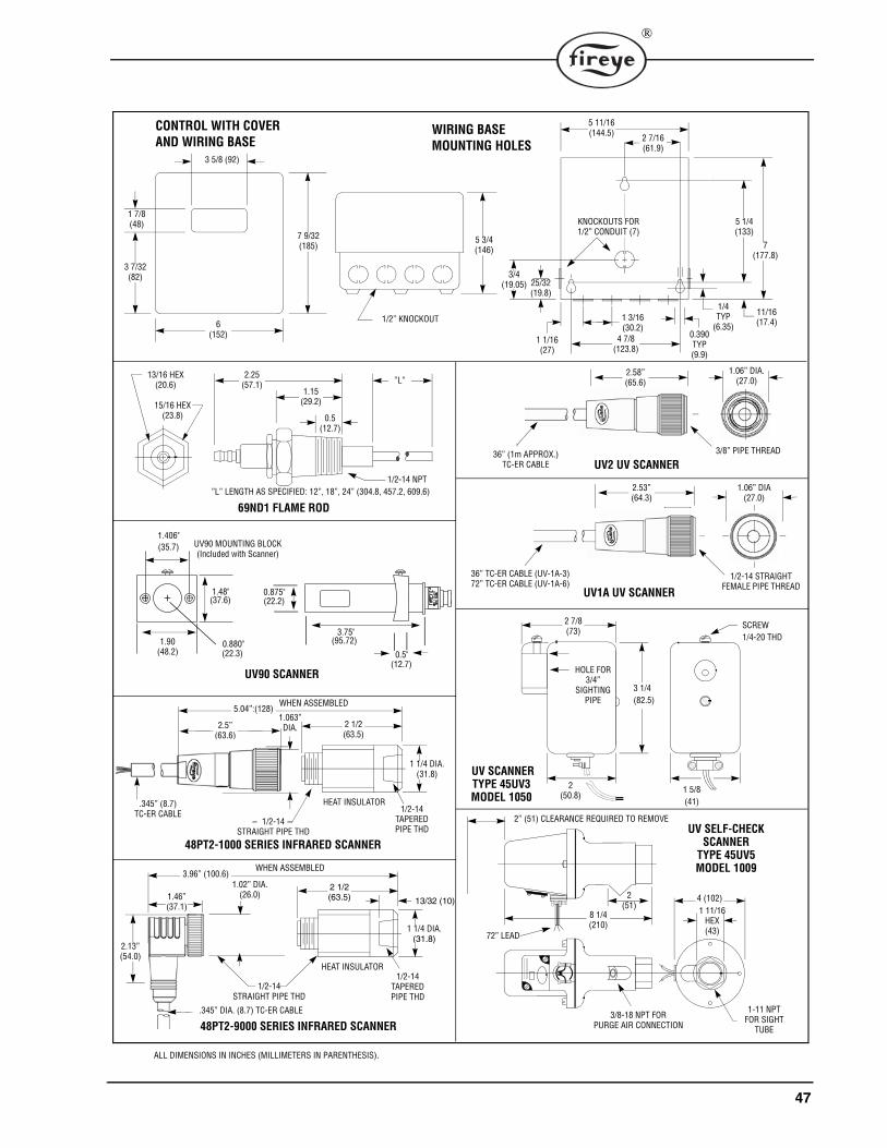
47
®
HOLE FOR3/4”
SIGHTINGPIPE
SCREW1/4-20 THD
2” (51) CLEARANCE REQUIRED TO REMOVE
2(51)
1/2-14STRAIGHT PIPE THD
3 5/8 (92)
7 9/32(185)
6(152)
1 7/8(48)
3 7/32(82)
5 3/4(146)
1/2” KNOCKOUT
CONTROL WITH COVERAND WIRING BASE
4 7/8(123.8)
5 11/16(144.5) 2 7/16
(61.9)
5 1/4(133)
7(177.8)
11/16(17.4)
3/4(19.05) 25/32
(19.8)
1/4TYP
(6.35)0.390TYP(9.9)
KNOCKOUTS FOR1/2” CONDUIT (7)
1 1/16(27)
1 3/16(30.2)
WIRING BASEMOUNTING HOLES
8 1/4(210)
3/8-18 NPT FORPURGE AIR CONNECTION
4 (102)1 11/16
HEX(43)
1-11 NPTFOR SIGHT
TUBE
UV2 UV SCANNER
UV SELF-CHECKSCANNER
TYPE 45UV5MODEL 1009
UV1A UV SCANNER
72” LEAD
2 7/8(73)
2(50.8)
1 5/8(41)
3 1/4(82.5)
UV SCANNERTYPE 45UV3MODEL 1050
2.25(57.1)
1.15(29.2)
0.5(12.7)
”L”
1/2-14 NPT
13/16 HEX(20.6)
15/16 HEX(23.8)
”L” LENGTH AS SPECIFIED: 12”, 18”, 24” (304.8, 457.2, 609.6)
69ND1 FLAME ROD
2 1/2(63.5)
WHEN ASSEMBLED
1 1/4 DIA.(31.8)
HEAT INSULATOR1/2-14
TAPEREDPIPE THD
1/2-14STRAIGHT PIPE THD
48PT2-1000 SERIES INFRARED SCANNER
2 1/2(63.5)
WHEN ASSEMBLED
1 1/4 DIA.(31.8)
HEAT INSULATOR1/2-14
TAPEREDPIPE THD
13/32 (10)
48PT2-9000 SERIES INFRARED SCANNER
ALL DIMENSIONS IN INCHES (MILLIMETERS IN PARENTHESIS).
0.880"(22.3)
1.90(48.2)
1.406"(35.7)
1.48"(37.6)
0.875"(22.2)
3.75"(95.72)
0.5"(12.7)
UV90 MOUNTING BLOCK(Included with Scanner)
UV90 SCANNER
36” (1m APPROX.)TC-ER CABLE
3/8” PIPE THREAD
1.06” DIA.(27.0)
2.58”(65.6)
2.53”(64.3)
1/2-14 STRAIGHTFEMALE PIPE THREAD
1.06” DIA(27.0)
36” TC-ER CABLE (UV-1A-3)72” TC-ER CABLE (UV-1A-6)
5.04”:(128)
.345” (8.7) TC-ER CABLE
2.5”(63.6)
1.063” DIA.
3.96” (100.6)1.02” DIA.
(26.0)
.345” DIA. (8.7) TC-ER CABLE
2.13”(54.0)
1.46”(37.1)
48
®
NOTICEWhen Fireye products are combined with equipment manufactured by others and/or integrated intosystems designed or manufactured by others, the Fireye warranty, as stated in its General Terms andConditions of Sale, pertains only to the Fireye products and not to any other equipment or to thecombined system or its overall performance.
WARRANTIESFIREYE guarantees for one year from the date of installation or 18 months from date of manufactureof its products to replace, or, at its option, to repair any product or part thereof (except lamps, elec-tronic tubes and photocells) which is found defective in material or workmanship or which otherwisefails to conform to the description of the product on the face of its sales order. THE FOREGOINGIS IN LIEU OF ALL OTHER WARRANTIES AND FIREYE MAKES NO WARRANTY OFMERCHANTABILITY OR ANY OTHER WARRANTY, EXPRESS OR IMPLIED. Except asspecifically stated in these general terms and conditions of sale, remedies with respect to any productor part number manufactured or sold by Fireye shall be limited exclusively to the right to replace-ment or repair as above provided. In no event shall Fireye be liable for consequential or special dam-ages of any nature that may arise in connection with such product or part.
FIREYE E-11013 Manchester Road OCTOBER 30, 2015Derry, New Hampshire 03038 USA Supersedes March 28, 2013www.fireye.com