Embed Size (px)
Citation preview

E-11 7/03
© 2003 American Boat & Yacht Council 0
E-11 AC and DC ELECTRICAL SYSTEMS ON BOATS
Table of Contents
11.1. PURPOSE ...................................................................................................................................... 1
11.2. SCOPE ........................................................................................................................................... 1
11.3. REFERENCED ORGANIZATIONS............................................................................................ 1
11.4. DEFINITIONS .............................................................................................................................. 1
11.5. REQUIREMENTS ........................................................................................................................ 3
11.6. SYSTEM VOLTAGE ..................................................................................................................... 6
11.7. POWER SOURCE ......................................................................................................................... 6
11.8. SHORE POWER POLARITY DEVICES................................................................................... 21
11.9. ISOLATION OF GALVANIC CURRENTS............................................................................... 21
11.10. LOAD CALCULATIONS ............................................................................................................ 22
11.11. PANELBOARD ........................................................................................................................... 24
11.12. OVERCURRENT PROTECTION .............................................................................................. 24
11.13. GROUND FAULT PROTECTION............................................................................................. 27
11.14. SWITCHES.................................................................................................................................. 28
11.15. PLUGS AND RECEPTACLES................................................................................................... 28
11.16. SYSTEM WIRING ...................................................................................................................... 29
11.17. APPLIANCES AND EQUIPMENT ........................................................................................... 33
11.18. DC GROUNDING AND BONDING .......................................................................................... 34


E-11 7/03
© 2003 American Boat & Yacht Council 1
E-11 AC and DC ELECTRICAL SYSTEMS ON BOATS Based on ABYC's assessment of the existing technology, and the problems associated with achieving the goals of this standard, ABYC recommends compliance with this standard for all systems and associated equipment manufactured and/or installed after July 31, 2004.
11.1. PURPOSE These standards are guides for the design, construction, and installation of direct current (DC) electrical systems on boats and of alternating current (AC) electrical systems on boats. NOTE: The United States Coast Guard has promulgated mandatory requirements for electrical systems in Title 33, CFR 183 Subpart I, Section 183. Refer to the CFR for complete, current federal requirements.
11.2. SCOPE These standards apply: 11.2.1. to direct current (DC) electrical systems on boats that operate at potentials of 50 volts or less and, EXCEPTION: Any wire that is part of an outboard engine assembly and does not extend inside the boat. 11.2.2. to boat alternating current (AC) electrical systems operating at frequencies of 50 or 60 hertz and less than 300 volts including shore powered systems up to the point of connection to the shore outlet and including the shore power cable.
11.3. REFERENCED ORGANIZATIONS ABYC - American Boat & Yacht Council, Inc., 3069 Solomon's Island Road, Edgewater, MD 21037-1416. Phone: 410-956-1050, Fax: 410-956-2737. Web site: www.abycinc.org CFR - Code Of Federal Regulations and other government publications. Obtain from the Superintendent Of Documents, United States Government Information, POB 371 954, Pittsburgh, PA 15250-7954 202-512-1800 or FAX 202-512-2250. Web site: www.access.gpo.gov An exerpted edition of the CFR is also available from ABYC, Inc. NEMA - National Electrical Manufacturer's Association, 1300 North 17th St, Suite 1847, Rosslyn, VA 22209. Phone: 703-841-3200, Fax: 703-841-5900. Web site: www.nema.org NFPA - National Fire Protection Association, One Batterymarch Park, Quincy, MA 02269-9101. Phone: 617-770-3000. Fax: 617-770-0700. Web-site: www.nfpa.org
SAE - Society of Automotive Engineers, 400 Commonwealth Drive, Warrendale, PA 15096 Phone: 724-776-4841. Fax: 724-776-5760. web site: www.sae.org USCG - United States Coast Guard, USCG Headquarters, Washington, DC, 25093-0001. Coast Guard Infoline: (800)-368-5647. Web site: www.uscgboating.org. UL - Underwriters Laboratories Marine Department, POB 13995, 12 Laboratory Drive, Research Triangle Park, NC 27709. Phone: 919-549-1400. Fax: 919-547-6000. Web site: www.ul.com
11.4. DEFINITIONS For the purposes of this standard, the following definitions apply. AC grounded conductor - A current carrying conductor that is intentionally maintained at ground potential. NOTE: This may be referred to as the neutral (white) conductor in AC electrical systems. AC grounding conductor (green or green with a yellow stripe) - A conductor, not normally carrying current, used to connect the metallic non-current carrying parts of AC electrical equipment to the AC grounding bus , engine negative terminal, or its bus, and to the source ground. NOTE: The source may be the shore AC power, an inverter, an isolation transformer or a generator. Battery cold cranking performance rating (0oF) - The discharge load in amperes that a battery at 17.8°C (0°F) can deliver for 30 seconds, and maintain a voltage of 1.2 volts per cell or higher, e.g., 7.2 volts for a 12 volt battery. Battery reserve capacity - The number of minutes a new fully charged battery at 26.7°C (80°F) can be continuously discharged at 25 amperes, and maintain a voltage of 1.75 volts or higher per cell, e.g., 10.5 volts for a 12 volt battery. DC grounded conductor - A current carrying conductor connected to the side of the power source

E-11 7/03
© 2003 American Boat & Yacht Council 2
Definitions - Continued that is intentionally maintained at boat ground potential. DC grounding conductor - A normally non-current carrying conductor used to connect metallic non-current carrying parts of direct current devices to the engine negative terminal, or its bus, for the purpose of minimizing stray current corrosion. Double insulation system - An insulation system comprised of basic insulation and supplementary insulation, with the two insulations physically separated and so arranged that they are not simultaneously subjected to the same deteriorating influences, e.g., temperature, contaminants, and the like, to the same degree. Engine negative terminal - The point on the engine at which the negative battery cable is connected. Equipment housing - The outside shell of equipment supplied by the manufacturer of the device, or a box, shell, or enclosure provided by the equipment installer. This shell provides personnel protection from electrical hazards, burns, rotating machinery, sharp edges, and provides protection to the device from mechanical damage or weather. Galvanic isolator - A device installed in series with the (AC) grounding (green) conductor of the shore power cable to effectively block low voltage (DC) galvanic current, but permit the passage of alternating current (AC) normally associated with the (AC) grounding (green) conductor. Ground - Ground applies to the potential of the earth's surface. The boat's ground is established by a conducting connection (intentional or accidental) with the earth, including any conductive part of the wetted surface of a hull. Ground fault circuit interrupter (GFCI) - A device intended for the protection of personnel that functions to de-energize a circuit, or portion thereof, within an established period of time when a current to ground exceeds some predetermined value that is less than that required to operate the overcurrent protective device of the supply circuit. Ground fault protector (GFP) - A device intended to protect equipment by interrupting the electric current to the load when a fault current to ground exceeds some predetermined value that is less than that required to operate the overcurrent protection device of that supply circuit. Ignition protection - The design and construction of a device such that under design operating conditions:
a. it will not ignite a flammable hydrocarbon mixture surrounding the device when an ignition source causes an internal explosion, or b. it is incapable of releasing sufficient electrical or thermal energy to ignite a hydrocarbon mixture, or c. the source of ignition is hermetically sealed. NOTES: 1. A flammable hydrocarbon mixture is a mixture of gasoline and air, CNG and air, or propane (LPG) and air between the lower explosive limit (LEL) and upper explosive limit (UEL). 2. It is not intended to require such devices to be "explosion proof" as that term is defined in the National Electrical Code of the NFPA pertaining to shore systems. 3. It is intended that the protection provided be generally equivalent to that of wiring permitted by this standard wherein a definite short or break would be necessary to produce an open spark. 4. Devices that are "explosion proof" are considered to be ignition protected when installed with the appropriate fittings to maintain their "explosion proof" integrity. 5. It is not intended to require such devices to be "intrinsically safe" per Article 504 of the National Electrical Code of the NFPA. 6. Devices that are "intrinsically safe" are considered to be ignition protected. 7. Test standards to determine ignition protection include SAE J1171, External Ignition Protection of Marine Electrical Devices, and UL 1500, Ignition Protection Test For Marine Products, and the electrical system requirements for boats in Title 33 CFR 183.410(a). Overcurrent protection device - A device, such as a fuse or circuit breaker, designed to interrupt the circuit when the current flow exceeds a predetermined value. Panelboard - An assembly of devices for the purpose of controlling and/or distributing power on a boat. It includes devices such as circuit breakers, fuses, switches, instruments, and indicators. Pigtails - External conductors that originate within an electrical component or appliance installed by their manufacturer. Polarized system AC- A system in which the grounded and ungrounded conductors are connected in the same relation to terminals or leads on devices in the circuit. Polarized system DC- A system in which the grounded (negative) and ungrounded (positive) conductors are connected in the same relation to terminals or leads on devices in the circuit.

E-11 7/03
© 2003 American Boat & Yacht Council 3
Definitions - Continued Readily accessible - Capable of being reached quickly and safely for effective use under emergency conditions without the use of tools. Self-limiting - A device whose maximum output is restricted to a specified value by its magnetic and electrical characteristics. Sheath - A material used as a continuous protective covering, such as overlapping electrical tape, woven sleeving, molded rubber, molded plastic, loom, or flexible tubing, around one or more insulated conductors. Shore power inlet - The fitting designed for mounting on the boat, of a reverse service type, requiring a female connector on the shore power cable in order to make the electrical connection. Switchboard - An assembly of devices for the purpose of controlling and/or distributing power on a boat. It may include devices such as circuit breakers, fuses, switches, instruments, and indicators. They are generally accessible from the rear as well as from the front, and are not intended to be installed in cabinets. Transformer, isolation - A transformer meeting the requirements of E-11.9.1 installed in the shore power supply circuit on a boat to electrically isolate all AC system conductors, including the AC grounding conductor (green) on the boat, from the AC system conductors of the shore power supply. Transformer, polarization - An isolated winding transformer, i.e., a "dry type," encapsulated lighting transformer, installed in the shore power supply circuit on the boat to electrically isolate the normally current carrying AC system conductors, but not the AC grounding conductor (green), from the normally current carrying conductors of the shore power supply. NOTE: Electrostatic shields that are available on some lighting transformers generally do not meet the fault current ampacity requirements of E- 11.9.1.3 Trip free circuit breaker - A resettable overcurrent protection device; designed so that the means of resetting cannot over ride the current interrupting mechanism. Watertight - So constructed that water will not enter the enclosure under the test conditions specified in NEMA Standard 250, Type 6P. Weatherproof - Constructed or protected so that exposure to the weather will not interfere with successful operation.
NOTE: For the purpose of this standard, as applied to marine use, weatherproof implies resistance to rain, spray, and splash.
11.5. REQUIREMENTS 11.5.1. IN GENERAL 11.5.1.1. AMBIENT TEMPERATURE The ambient temperature of machinery spaces is considered to be 50°C (122°F) and of all other spaces is considered to be 30°C (86°F). The ambient temperature for rating of shore power cables shall be 30°C (86°F). 11.5.1.2. MARKING 11.5.1.2.1. Marking of Controls - All switches and electrical controls shall be marked to indicate their usage.
EXCEPTION: A switch or electrical control whose purpose is obvious and whose mistaken operation will not cause a hazardous condition. 11.5.1.2.2. Marking of Equipment - Electrical equipment, except a part of an identified assembly, such as an engine, shall be marked or identified by the manufacturer to indicate: 11.5.1.2.2.1. manufacturer's identification, 11.5.1.2.2.2. product identification or model number, 11.5.1.2.2.3. AC electrical rating in volts and amperes or volts and watts, OR 11.5.1.2.2.4. DC electrical rating in volts as appropriate. 11.5.1.2.2.5. Rated amperage or wattage of DC electrical equipment shall be available. NOTE: Rated amperage or wattage of DC electrical equipment may be marked on the device. (See E-11.5.1.2.2.5) 11.5.1.2.2.6. The terminal polarity or identification, if necessary to operation 11.5.1.2.2.7. Phase and frequency, if applicable, and 11.5.1.2.2.8. "Ignition Protected," if applicable. This shall be identified by a marking such as "SAE J1171 Marine," "UL Marine-Ignition Protected," or "Ignition Protected."

E-11 7/03
© 2003 American Boat & Yacht Council 4
11.5.1.3. IGNITION PROTECTION 11.5.1.3.1. Potential electrical sources of ignition located in spaces containing gasoline powered machinery, or gasoline fuel tank(s), or joint fitting(s), or other connection(s) between components of a gasoline system, shall be ignition protected, unless the component is isolated from a gasoline fuel source as described in E-11.5.1.3.3 (See Figure 1, Figure 2, Figure 3, Figure 4, Figure 5, Figure 6, Figure 7, and Figure 8.) EXCEPTION: 1. Boats using diesel fuel as the only fuel source. 2. Outboard engines mounted externally or in compartments open to the atmosphere in accordance with the requirements of ABYC H-2, Ventilation of Boats Using Gasoline. 11.5.1.3.2. If LPG or CNG is provided on the boat, all electrical potential sources of ignition located in compartments containing LPG/CNG appliances, cylinders, fittings, valves or regulators shall be ignition protected.
EXCEPTION: For boats with LPG/CNG systems installed in accordance with ABYC A-1, Marine Liquefied Petroleum Gas (LPG) Systems, or ABYC A-22, Marine Compressed Natural Gas (CNG) Systems, and stoves that comply with ABYC A-3, Galley Stoves, electrical devices in the following compartments are excepted: 1. Accommodation spaces 2. Open compartments having at least 15 square inches (968 mm2) of open area per cubic foot (0.03 m2) of net compartment volume exposed to the atmosphere outside of the craft. 11.5.1.3.3. An electrical component is isolated from a gasoline fuel source if 11.5.1.3.3.1. a bulkhead that meets the requirements of E-11.5.1.3.4 (Figure 7 and Figure 8) is between the electrical components and the gasoline fuel source; or 11.5.1.3.3.2. the electrical component is 11.5.1.3.3.2.1. lower than the gasoline fuel source and a means is provided to prevent gasoline fuel and gasoline fuel vapors that may leak from the gasoline fuel sources from becoming exposed to the electrical component, or 11.5.1.3.3.2.2. higher than the gasoline fuel source and a deck or other enclosure is between it and the gasoline fuel source, or
11.5.1.3.3.2.3. the distance between the electrical component and the gasoline fuel source is at least two feet (610mm), and the space is open to the atmosphere. (See Figure 6.)
11.5.1.3.4. Each bulkhead required by E-11.5.1.3.3.1 shall (see Figure 7 and Figure 8.) 11.5.1.3.4.1. separate the electrical component from the fuel source, and extend both vertically and horizontally the distance of the open space between the gasoline fuel source and the ignition source, and 11.5.1.3.4.2. resist a water level that is 12 inches (305 mm) high or one-third of the maximum height of the bulkhead, whichever is less, without seepage of more than one-quarter fluid ounce (7.5 cc) of fresh water per hour; and 11.5.1.3.4.3. shall have no opening higher than 12 inches (305 mm) or one-third the maximum height of the bulkhead, whichever is less, unless the opening is used for the passage of conductors, piping, ventilation ducts, mechanical equipment, and similar items, or doors, hatches and access panels, and the maximum annular space around each item or door, hatch, or access panel must not be more than one-quarter inch (6mm) 11.5.1.3.5. To minimize the potential for migration of carbon monoxide from machinery compartments containing gasoline engines to adjacent accommodation compartments, bulkhead and deck penetrations shall be in accordance with the requirements of ABYC H-2, Ventilation of Boats Using Gasoline. NOTE: For additional information (See ABYC TH-22, Educational Information About Carbon Monoxide, and ABYC TH-23, Design, Construction, and Testing of Boats in Consideration of Carbon Monoxide.) 11.5.2. REQUIREMENTS FOR DC SYSTEMS 11.5.2.1. Two-Wire System - All direct current (DC) electrical distribution systems shall be of the two-wire type. (See Figures 9A and 9 B, and Figures 10 A and 10 B.) EXCEPTION: Engine mounted equipment. 11.5.2.2. DC Grounding Systems and Bonding - A metallic hull, or the bonding and DC grounding systems, shall not be used as a return conductor. (See Figures 9A and 9 B, and Figures 10 A and 10 B, and E-11.18 DC Grounding and Bonding.) 11.5.2.3. Grounded Systems - If one side of a two-wire direct current system is connected to ground,

E-11 7/03
© 2003 American Boat & Yacht Council 5
Requirements – DC - Continued it shall be the negative side and polarized as defined in E-11.4. 11.5.2.4. Multiple Engine Installation - If a boat has more than one engine with a grounded cranking motor, which includes auxiliary generator engine(s), the engines shall be connected to each other by a common conductor that can carry the cranking motor current of each of the grounded cranking motor circuits. Outboard engines shall be connected at the battery negative terminals. 11.5.2.5. Crossover (Parallel) Cranking Motor Circuits - In multiple inboard engine installations, which includes auxiliary generator(s) with cross-over (parallel) cranking motor systems, the engines shall be connected together with a cable large enough to carry the cranking motor current. This cable and its terminations shall be in addition to, and independent of, any other electrical connections to the engines including those required in E-11.5.2.4.
EXCEPTIONS: 1. Installations using ungrounded DC electrical systems. 2. Outboard engines. 11.5.2.6. If a paralleling switch is installed, it shall be capable of carrying the largest cranking motor current. NOTE: A paralleling switch may be either of the maintained contact or momentary contact type. 11.5.2.7. DC System Negative Connections 11.5.2.7.1. If an alternating current (AC) system is installed, the main AC system grounding bus shall be connected to 11.5.2.7.1.1. the engine negative terminal or the DC main negative bus on grounded DC systems, or 11.5.2.7.1.2. the boat’s DC grounding bus in installations using ungrounded DC electrical systems. (See FIGURE 18) 11.5.2.7.2. The negative terminal of the battery, and the negative side of the DC system, shall be connected to the engine negative terminal or its bus. On boats with outboard motors, the load return lines shall be connected to the battery negative terminal or its bus, unless specific provision is made by the outboard motor manufacturer for connection to the engine negative terminal. 11.5.2.7.3. If an accessory negative bus with provision for additional circuits is used for the connection of accessories, the ampacity of this bus, and the conductor connected to the engine negative
terminal or the DC main negative bus, shall be at least equal to the ampacity of the feeder(s) to the panelboard(s) supplying the connected accessories. (See Figures 9A and 9 B, and Figures 10 A and 10 B.) 11.5.2.7.4. If the negative side of the DC system is to be connected to ground, the connection shall be made only from the engine negative terminal, or its bus, to the DC grounding bus. This connection shall be used only as a means of maintaining the negative side of the circuit at ground potential and is not to carry current under normal operating conditions. 11.5.2.7.5. Continuously energized parts, such as positive battery terminals and both ends of all wire connected thereto, shall be physically protected with boots, or other form of protection, that cover all energized surfaces to prevent accidental short circuits.
EXCEPTION: Circuits that have overcurrent protection at the source of power in accordance with E-11.12. 11.5.3. FOR AC SYSTEMS 11.5.3.1. The system shall be polarized as defined in E- 11.4 11.5.3.2. A grounded neutral system is required. The neutral for AC power sources shall be grounded only at the following points: 11.5.3.2.1. The shore power neutral is grounded through the shore power cable and shall not be grounded on board the boat. 11.5.3.2.2. The secondary neutral of an isolation transformer or polarization transformer shall be grounded at the secondary of an isolation or polarization transformer. (See DIAGRAM 5 , DIAGRAM 6, DIAGRAM 7, DIAGRAM 8, DIAGRAM 9, DIAGRAM 10, DIAGRAM 11, DIAGRAM 12, and DIAGRAM 13 . See Exception.) 11.5.3.2.3. The generator neutral shall be grounded at the generator. (See DIAGRAM 2 or DIAGRAM 4.) 11.5.3.2.4. The inverter output neutral shall be grounded at the inverter. The inverter output neutral shall be disconnected from ground when the inverter is operating in the charger or the feed-through mode(s). (See ABYC A-25, Power Inverters.) EXCEPTION: Exception to E-11.5.3.2.2., E-11.5.3.2.3 and E-11.5.3.2.4: For systems using an isolation transformer or polarization transformer, both the generator or inverter neutral and the transformer secondary neutrals may be grounded at the AC main grounding bus instead of at the generator, inverter, or transformer secondaries. (See DIAGRAM 5 .)

E-11 7/03
© 2003 American Boat & Yacht Council 6
Requirements - AC - Continued 11.5.3.3. The main AC system grounding bus shall be connected to 11.5.3.3.1. the engine negative terminal or the DC main negative bus on grounded DC systems, or 11.5.3.3.2. the boat’s DC grounding bus in installations using ungrounded DC electrical systems. 11.5.3.4. In AC circuit, all current carrying conductors and the grounding conductor shall be run together in the same cable, bundle or raceway. 11.5.3.5. There shall be no switch or overcurrent protection device in the AC grounding (green) conductor. 11.5.3.6. When more than one shore power inlet is used, the shore power neutrals shall not be connected together on board the boat. 11.5.3.7. Individual circuits shall not be capable of being energized by more than one source of electrical power at a time. Each shore power inlet, generator, or inverter is a separate source of electrical power. 11.5.3.7.1. The transfer from one power source circuit to another shall be made by a means that opens all current-carrying conductors, including neutrals, before closing the alternate source circuit, and prevents arc-over between sources. 11.5.3.7.2. A means for disconnecting all power sources from the load shall be provided at the same location. EXCEPTION: Exception to E-11.5.3.7 and its subsections: The grounded neutral from a polarization transformer, isolation transformer, generator or inverter may be permanently connected to the same main AC grounding bus (See E-11.7.2.2, DIAGRAM 5 ) and is not required to be switched. 11.5.3.8. Energized parts of electrical equipment shall be guarded against accidental contact by the use of enclosures or other protective means that shall not be used for non-electrical equipment. 11.5.3.8.1. Access to energized parts of the electrical system shall require the use of hand tools.
11.6. SYSTEM VOLTAGE 11.6.1. FOR AC SYSTEMS 11.6.1.1. Nominal system voltages for AC electrical systems shall be selected from the following: 11.6.1.1.1. 120 volts AC, single phase;
11.6.1.1.2. 240 volts AC, single phase; 11.6.1.1.3. 120/240 volts AC, single phase; 11.6.1.1.4. 120/240 volts AC, delta three phase; or 11.6.1.1.5. 120/208 volts AC, Wye three phase.
11.7. POWER SOURCE 11.7.1. FOR DC SYSTEMS 11.7.1.1. BATTERY 11.7.1.1.1. BATTERY CAPACITY 11.7.1.1.1.1. The battery, or battery bank, shall have at least the cold cranking amperage required by the engine manufacturer. 11.7.1.1.1.2. The battery, or battery bank, shall have a rated reserve capacity so that, 11.7.1.1.1.2.1. for boats with one battery charging source the battery shall be capable of supplying the total load of Column A in TABLE II for a minimum of 1 1/2 hours; or 11.7.1.1.1.2.2. for boats with multiple simultaneous battery charging sources, the capacity of all charging sources, except the largest charging source shall be subtracted from the total load of Column A. The battery shall be capable of supplying the resulting differences for a minimum of 1 1/2 hours. 11.7.1.1.2. Use TABLE I for reserve capacity values, or the following formula derived from Peukert’s equation to calculate the required reserve capacity: T = 0.0292 x I 1.225 x 60 T = battery reserve capacity in minutes I = total current of column A in amperes per E-11.10.1.1

E-11 7/03
© 2003 American Boat & Yacht Council 7
Power Source – DC - Continued
TABLE I - RESERVE CAPACITY OF BATTERIES DERIVED FROM PEUKERT’S EQUATION Amperes
Reserve Capacity Minutes
5 13 10 29 15 48 20 69 25 90 30 113 35 136 40 160 45 185 55 211 55 237 60 264 65 291 70 318 75 347 80 375 85 404 90 433 95 463 100 493 105 523 110 554 NOTE: The values in Table I are calculated using Peukert’s equation. 11.7.1.2. BATTERY SWITCH
11.7.1.2.1. A battery switch shall be installed in the positive conductor(s) from each battery or battery bank with a CCA rating greater than 800 amperes.
EXCEPTIONS: 1. Trolling motor conductors connected to dedicated trolling motor batteries provided with overcurrent protection at the battery and a manual means of electrical disconnect separate from the trolling motor controls. 2. Conductors supplying the following may be connected to the battery side of the switch (See FIGURE 11 ): a. Electronic equipment with continuously powered memory; b. Safety equipment such as bilge pumps, alarms, CO detectors and bilge blowers; c. Battery charging equipment.
11.7.1.2.2. A battery switch shall be mounted in a readily accessible location as close as practicable to the battery. 11.7.1.2.3. Battery Switch Ratings - The intermittent rating of a battery switch shall not be less than the maximum cranking current of the largest engine cranking motor that it serves. The minimum continuous rating of a battery switch shall be the total of the ampacities of the main overcurrent protection devices connected to the battery switch, or the ampacity of the feeder cable to the switch, whichever is less. 11.7.2. FOR AC SYSTEMS 11.7.2.1. SHORE POWER 11.7.2.1.1. SHORE POWER SUPPLY 11.7.2.1.1.1. Power Inlet - The receptacle, or receptacles, installed to receive a connecting cable to carry AC shore power aboard shall be a male type connector. 11.7.2.1.1.1.1. Power inlets installed in locations subject to rain, spray, or splash shall be weatherproof whether or not in use. 11.7.2.1.1.1.2. Power inlets installed in areas subject to flooding or momentary submersion shall be of a watertight design whether or not in use. 11.7.2.1.1.1.3. Metallic power inlets installed on metallic or carbon fiber reinforced boats using an isolation transformer or a galvanic isolator shall be insulated from metallic structure and components. On non-metallic boats using an isolation transformer or a galvanic isolator the power inlet shall be insulated from metallic components connected to the boat's ground. 11.7.2.1.1.2. Shore Power Cable – On each boat equipped with an AC shore power system, a shore power cable that contains the conductors for the power circuit and a grounding (green) conductor shall be provided. 11.7.2.1.1.2.1. Except where the shore power cable is permanently connected to the boat, the boat end of this cable shall be terminated with a locking and grounding female type connector to match the boat power inlet. (See FIGURE 13 and FIGURE 14 .) 11.7.2.1.1.2.2. The shore power cable shall be flexible cord with the minimum properties of Type SOW, STW, STOW, SEOW, or STOOW, and shall be suitable for outdoor use. The shore connection end of this cable shall be fitted with a locking and grounding type plug with the required number of poles and shall comply with Article 555 of the National Electrical

E-11 7/03
© 2003 American Boat & Yacht Council 8
Power Source – AC – Continued Code. (See FIGURE 13 or FIGURE 14 and Table VIII A) 11.7.2.1.1.3. Shore Power Inlet Warning 11.7.2.1.1.3.1. Labels and warnings shall comply with ABYC T-5, Safety Signs and Labels. 11.7.2.1.1.3.2. Labels shall include the following informational elements: 11.7.2.1.1.3.2.1. the signal word for the level of hazard intensity; 11.7.2.1.1.3.2.2. nature of the hazard; 11.7.2.1.1.3.2.3. consequences that can result if the instructions to avoid the hazard are not followed; and 11.7.2.1.1.3.2.4. instructions on how to avoid the hazard. 11.7.2.1.1.3.3. A permanently mounted waterproof warning sign shall be located at each shore power inlet location on the boat. NOTE: An example of such a label follows:
WARNING Electrical shock and fire hazard. Failure to follow these instructions may result in injury or death. (1) Turn off the boat's shore power connection switch before connecting or disconnecting the shore power cable. (2) Connect shore power cable at the boat first. (3) If polarity-warning indicator is activated, immediately disconnect cable. (4) Disconnect shore power cable at shore outlet first. (5) Close shore power inlet cover tightly. DO NOT ALTER SHORE POWER CABLE CONNECTORS
EXCEPTIONS: 1. Item 3 is not required if a polarity indicator is not installed. (See E-11.8.) 2. Items 2 and 4 are not required for permanently connected shore power cables.

E-11 7/03
© 2003 American Boat & Yacht Council 9
Power Source – AC – Continued 11.7.2.2. APPLICATION OF TYPES OF SHORE POWER CIRCUITS 11.7.2.2.1. Single Phase 120-Volt Systems with Shore-Grounded (White) Neutral Conductor and Grounding (Green) Conductor. (See DIAGRAM 1, DIAGRAM 2, and DIAGRAM 3.) 11.7.2.2.1.1. The shore grounded (white) and ungrounded shore current carrying conductors are connected from the shore power inlet to the boat's AC electrical system through an overcurrent protection device that simultaneously opens both current-carrying conductors. Fuses shall not be used instead of simultaneous trip devices. (See E-11.12.2.9.2.) 11.7.2.2.1.2. Neither the shore grounded (white) neutral conductor nor the ungrounded current carrying conductors shall be grounded on the boat. (See E-11.5.3.2.1.) 11.7.2.2.1.3. When more than one shore power inlet is used, the shore power neutrals shall not be connected together on the boat. (See E-11.5.3.6.) 11.7.2.2.1.4. The shore-grounding (green) conductor is connected, without interposing switches or overcurrent protection devices (See E-11.5.3.5.), from the shore power inlet to
11.7.2.2.1.4.1. an optional galvanic isolator, and then to 11.7.2.2.1.4.2. all non-current carrying parts of the boat’s AC electrical system, including 11.7.2.2.1.4.3. the engine negative terminal or its bus. 11.7.2.2.1.5. If an optional galvanic isolator is used, the shell of a metallic shore power inlet shall be electrically insulated from the boat. 11.7.2.2.1.6. If the boat's AC electrical system includes branch circuit breakers, the branch circuit breakers shall simultaneously open both current carrying conductors unless a polarity indicating device is provided. (See E-11.12.2.6.1 Exception.) 11.7.2.2.1.7. Polarization of conductors must be observed in all circuits (see DIAGRAM 1, DIAGRAM 2, and DIAGRAM 3)
DIAGRAM 1 – (See E-11.7.2.2.1.) Note: this diagram does not illustrate a complete system. Refer to the appropriate text

E-11 7/03
© 2003 American Boat & Yacht Council 10
Power Source – Application of Type of Shore Power Circuits - Continued DIAGRAM 2 – (See E-11.7.2.2.1.) Note: This diagram does not illustrate a complete system. Refer to appropriate text.
DIAGRAM 3 – (See E-11.7.2.2.1.) Note: This diagram does not illustrate a complete system. Refer to appropriate text.

E-11 7/03
© 2003 American Boat & Yacht Council 11
Power Source - Application of Type of Shore Power Circuits - Continued 11.7.2.2.2. Single Phase 120/240 Volt System With Shore Grounded (White) Neutral Conductor And Grounding (Green) Conductor. (See DIAGRAM 4.) 11.7.2.2.2.1. Each ungrounded shore conductor is connected from the shore power inlet to the boat's AC electrical system through an overcurrent protection device that simultaneously opens both ungrounded current carrying conductors. Fuses shall not be used instead of the simultaneous trip devices. (See E-11.12.2.9.2.) 11.7.2.2.2.2. The shore grounded (white) neutral conductor from the shore power inlet is connected to the neutral conductors in the boat's AC electrical system without overcurrent protection devices. (See E- 11.5.3.2.) EXCEPTION: An overcurrent protection device may be used in the shore grounded neutral conductor provided the overcurrent protection device simultaneously opens all current carrying conductors in the circuits. 11.7.2.2.3. The generator or inverter neutral is grounded at the generator or inverter. (See E-11.5.3.2.3.) 11.7.2.2.4. Neither the shore grounded (white) neutral conductor nor ungrounded current carrying conductors shall be grounded on the boat. (See E-11.5.3.2.1.)
11.7.2.2.5. When more than one shore power inlet is used, the shore power neutrals shall not be connected together on the boat. (See E-11.5.3.6.) 11.7.2.2.6. The shore-grounding (green) conductor is connected, without interposing switches or overcurrent protection devices (See E-11.5.2.5), from the shore power inlet to 11.7.2.2.6.1. an optional galvanic isolator, and then to 11.7.2.2.6.2. all non-current carrying parts of the boat’s AC electrical system, including 11.7.2.2.6.3. the engine negative terminal or its bus. 11.7.2.2.6.4. If an optional galvanic isolator is used the shell of a metallic shore power inlet shall be electrically insulated from the boat. 11.7.2.2.7. 120-volt branch circuit breakers are permitted to be single pole in the ungrounded current carrying conductors. (See E-11.12.2.6.1 Exception.) 11.7.2.2.8. 240-volt branch circuit breakers shall simultaneously open all current carrying conductors. (See E-11.12.2.6.2.) 11.7.2.2.9. Polarization of conductors must be observed in all circuits. (See DIAGRAM 4.)
DIAGRAM 4 – (See E-11.7.2.2.2) Note: This diagram does not illustrate a complete system. Refer to appropriate text
E-11 7/03
© 2003 American Boat & Yacht Council 12
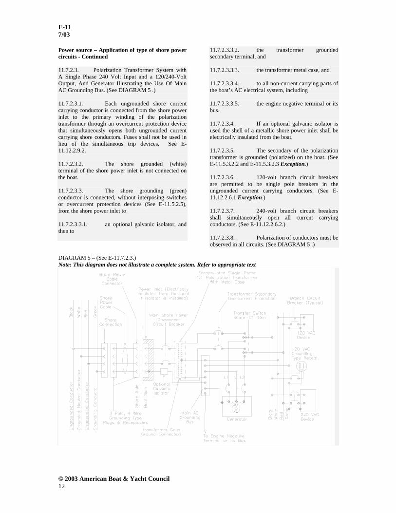
Power source – Application of type of shore power circuits - Continued 11.7.2.3. Polarization Transformer System with A Single Phase 240 Volt Input and a 120/240-Volt Output, And Generator Illustrating the Use Of Main AC Grounding Bus. (See DIAGRAM 5 .) 11.7.2.3.1. Each ungrounded shore current carrying conductor is connected from the shore power inlet to the primary winding of the polarization transformer through an overcurrent protection device that simultaneously opens both ungrounded current carrying shore conductors. Fuses shall not be used in lieu of the simultaneous trip devices. See E-11.12.2.9.2. 11.7.2.3.2. The shore grounded (white) terminal of the shore power inlet is not connected on the boat. 11.7.2.3.3. The shore grounding (green) conductor is connected, without interposing switches or overcurrent protection devices (See E-11.5.2.5), from the shore power inlet to 11.7.2.3.3.1. an optional galvanic isolator, and then to
11.7.2.3.3.2. the transformer grounded secondary terminal, and 11.7.2.3.3.3. the transformer metal case, and 11.7.2.3.3.4. to all non-current carrying parts of the boat’s AC electrical system, including 11.7.2.3.3.5. the engine negative terminal or its bus. 11.7.2.3.4. If an optional galvanic isolator is used the shell of a metallic shore power inlet shall be electrically insulated from the boat. 11.7.2.3.5. The secondary of the polarization transformer is grounded (polarized) on the boat. (See E-11.5.3.2.2 and E-11.5.3.2.3 Exception.) 11.7.2.3.6. 120-volt branch circuit breakers are permitted to be single pole breakers in the ungrounded current carrying conductors. (See E-11.12.2.6.1 Exception.) 11.7.2.3.7. 240-volt branch circuit breakers shall simultaneously open all current carrying conductors. (See E-11.12.2.6.2.) 11.7.2.3.8. Polarization of conductors must be observed in all circuits. (See DIAGRAM 5 .)
DIAGRAM 5 – (See E-11.7.2.3.) Note: This diagram does not illustrate a complete system. Refer to appropriate text

E-11 7/03
© 2003 American Boat & Yacht Council 13
Power source – Application of type of shore power circuits - Continued 11.7.2.4. Isolation Transformer System with Single Phase 120 Volt Input, 120-Volt Output with Boat Grounded Secondary. Transformer Shield and Metal Case Grounded on the Shore. (See DIAGRAM 6.) 11.7.2.4.1. The shore grounded (white) and ungrounded shore current carrying conductors are connected from the shore power inlet to the primary winding of the isolation transformer through an overcurrent protection device that simultaneously opens both current-carrying shore conductors. Fuses shall not be used instead of the simultaneous trip devices. (See E-11.12.2.9.2.) 11.7.2.4.2. The shore grounding (green) conductor is connected, without interposing switches or overcurrent protection devices (See E-11.5.2.5), from the shore power inlet to 11.7.2.4.2.1. the transformer metal case, and 11.7.2.4.2.2. the transformer shield. 11.7.2.4.3. The shell of a metallic shore power inlet shall be electrically insulated from the boat.
11.7.2.4.4. The transformer case is protected by a ventilated nonconductive enclosure. 11.7.2.4.5. The secondary of the isolation transformer is grounded (polarized) on the boat. (See E-11.5.3.2.2 and E-11.5.3.2.3 Exception.) 11.7.2.4.6. The boat grounding system (green) conductor is connected, without interposing switches or overcurrent protection devices (See E-11.5.2.5), from 11.7.2.4.6.1. the transformer grounded secondary terminal , and 11.7.2.4.6.2. to all non-current-carrying parts of the boat's AC electrical system, including 11.7.2.4.6.3. the engine negative terminal or its bus. 11.7.2.4.7. 120 -volt branch circuit breakers are permitted to be single pole breakers in the ungrounded current-carrying conductors. (See E-11.12.2.6.1 Exception.) 11.7.2.4.8. Polarization of conductors must be observed in all circuits. (See DIAGRAM 6.)
DIAGRAM 6 – (See E-11.7.2.4.) Note: This diagram does not illustrate a complete system. Refer to appropriate text

E-11 7/03
© 2003 American Boat & Yacht Council 14
Power source – Application of type of shore power circuits - Continued 11.7.2.5. Isolation Transformer System with a Single Phase 120-Volt Input, 120-Volt Output with Boat Grounded Secondary. Transformer Shield Grounded On the Shore. Transformer Metal Case Grounded on the Boat. (See DIAGRAM 7.) 11.7.2.5.1. The shore grounded (white) and ungrounded shore current carrying conductors are connected from the shore power inlet to the primary winding of the isolation transformer through an overcurrent protection device that simultaneously opens both current carrying shore conductors. Fuses shall not be used instead of the simultaneous trip devices. (See E- 11.12.2.9.2.) 11.7.2.5.2. The shore grounding (green) conductor is connected, without interposing switches or overcurrent protection devices (See E-11.5.3.4), from the shore power inlet to 11.7.2.5.2.1. the isolation transformer shield. 11.7.2.5.3. The shell of a metallic shore power inlet shall be electrically insulated from the boat.
11.7.2.5.4. The secondary of the isolation transformer is grounded (polarized) on the boat. (See E-11.5.3.2.2 and E-11.5.3.2.3 Exception.) 11.7.2.5.5. The boat grounding (green) conductor is connected, without interposing switches or overcurrent protection devices (See E-11.5.3.4), from 11.7.2.5.5.1. the transformer grounded secondary terminal, 11.7.2.5.5.2. the transformer metal case , and 11.7.2.5.5.3. to all non-current-carrying parts of the boat's AC electrical system, including 11.7.2.5.5.4. the engine negative terminal or its bus. 11.7.2.5.5.5. 120-volt branch circuit breakers are permitted to be single pole breakers in the ungrounded current carrying conductors. (See E-11.12.2.6.1 Exception.) 11.7.2.5.5.6. Polarization of conductors must be observed in all circuits. (See E-11.5.3.1.)
DIAGRAM 7 – (See E-11.7.2.5.) Note: This diagram does not illustrate a complete system. Refer to appropriate text

E-11 7/03
© 2003 American Boat & Yacht Council 15
Power source – Application of type of shore power circuits – Continued 11.7.2.6. Isolation Transformer System with a Single Phase 120-Volt Output with Ground Fault Protection and Boat Grounded Secondary. Transformer Shield and Metal Case Grounded on the Boat. (See DIAGRAM 8.) 11.7.2.6.1. The shore grounded (white) and ungrounded shore current carrying conductors are connected from the shore power inlet to the primary winding of the isolation transformer through a ground fault protection device (See E-11.13) that simultaneously opens both current carrying shore conductors. Fuses shall not be used instead of the simultaneous trip devices. (See E-11.12.2.9.2.) 11.7.2.6.2. The shore grounding (green) terminal of the shore power inlet is not connected on the boat. 11.7.2.6.3. The shell of a metallic shore power inlet shall be electrically insulated from the boat. 11.7.2.6.4. The secondary of the isolation transformer is grounded (polarized) on the boat. (See E-11.5.3.2.2 and E-11.5.3.2.3 Exception.)
11.7.2.6.5. The boat grounding (green) conductor is connected, without interposing switches or overcurrent protection devices (See E-11.5.2.5), from 11.7.2.6.5.1. the transformer grounded secondary terminal, 11.7.2.6.5.2. the transformer metal case, 11.7.2.6.5.3. the transformer shield, and 11.7.2.6.5.4. to all non-current-carrying parts of the boat's AC electrical system, including 11.7.2.6.5.5. the engine negative terminal or its bus. 11.7.2.6.5.6. 120-volt branch circuit breakers are permitted to be single-pole breakers in the ungrounded current-carrying conductors. (See E-11.12.2.6.1 Exception.) 11.7.2.6.5.7. Polarization of conductors must be observed in all circuits. (See DIAGRAM 8.)
DIAGRAM 8 – (See E-11.7.2.6.) Note: This diagram does not illustrate a complete System. Refer to appropriate text.

E-11 7/03
© 2003 American Boat & Yacht Council 16
Power source – Application of type of shore power circuits - Continued 11.7.2.7. Isolation Transformer System with Single Phase 240 Volt Input, 120/240-Volt Output with a Boat Grounded Secondary. Transformer Shield and Metal Case Grounded on the Shore. (See DIAGRAM 9.) 11.7.2.7.1. Each ungrounded shore current carrying conductor is connected from the shore power inlet to the primary winding of the isolation transformer through an overcurrent protection device that simultaneously opens both current-carrying shore conductors. Fuses shall not be used instead of the simultaneous trip devices. (See E-11.12.2.9.2.) 11.7.2.7.2. The shore grounded (white) terminal of the shore power inlet is not connected on the boat. 11.7.2.7.3. The shore grounding (green) conductor is connected, without interposing switches or overcurrent protection devices (See E-11.5.3.4), from the shore power inlet to 11.7.2.7.3.1. the transformer metal case and 11.7.2.7.3.2. the transformer shield. 11.7.2.7.4. The shell of a metallic shore power inlet shall be electrically insulated from the boat.
11.7.2.7.5. The transformer case is protected by a ventilated non-conductive enclosure. 11.7.2.7.6. The secondary of the isolation transformer is grounded (polarized) on the boat. (See E-11.5.3.2.2 and E-11.5.3.2.3 Exception.) 11.7.2.7.7. The boat-grounding (green) conductor is connected, without interposing switches or overcurrent protection devices (See E-11.5.2.5.), from 11.7.2.7.7.1. the transformer grounded secondary terminal, and 11.7.2.7.7.2. to all non-current carrying parts of the boat’s AC electrical system, including 11.7.2.7.7.3. the engine negative terminal or its bus. 11.7.2.7.8. 120-volt branch circuit breakers are permitted to be single pole breakers in the ungrounded current carrying conductors. (See E-11.12.2.6.1 Exception.) 11.7.2.7.9. 240-volt branch circuit breakers shall simultaneously open all current-carrying conductors. (See E-11.12.2.6.2.) 11.7.2.7.10. Polarization of conductors must be observed in all circuits. (See DIAGRAM 9.)
DIAGRAM 9 – (See E-11.7.2.7.) Note: This diagram does not illustrate a complete system. Refer to appropriate text

E-11 7/03
© 2003 American Boat & Yacht Council 17
Power source – Application of type of shore power circuits - Continued 11.7.2.8. Isolation Transformer System with Single Phase 240 Volt Input, 120/240-Volt Output with Boat Grounded Secondary. Transformer Shield Grounded on the Shore. Transformer Metal Case Grounded on the Boat. (See DIAGRAM 10.) 11.7.2.8.1. Each ungrounded shore current carrying conductor is connected from the shore power inlet to the primary winding of the isolation transformer through an overcurrent protection device that simultaneously opens both current carrying shore conductors. Fuses shall not be used instead of simultaneous trip devices. (See E-11.12.2.9.2.) 11.7.2.8.2. The shore grounded (white) terminal of the shore power inlet is not connected on the boat. 11.7.2.8.3. The shore grounding (green) conductor is connected, without interposing switches or overcurrent protection devices (See E-11.5.2.5), from the shore power inlet to the transformer shield. 11.7.2.8.4. The shell of a metallic shore power inlet shall be electrically insulated from the boat.
11.7.2.8.5. The secondary of the isolation transformer is grounded (polarized) on the boat. (See E-11.5.3.2.2 and E-11.5.3.2.3 Exception.) 11.7.2.8.6. The boat grounding (green) conductor is connected, without interposing switches or overcurrent protection devices (See E-11.5.3.4), from 11.7.2.8.6.1. the transformer grounded secondary terminal, 11.7.2.8.6.2. the transformer metal case, and 11.7.2.8.6.3. to all non-current carrying parts of the boat’s AC electrical system, including 11.7.2.8.6.4. the engine negative terminal or its bus. 11.7.2.8.7. 120-volt branch circuit breakers are permitted to be single pole breakers in the ungrounded current-carrying conductors. (See E-11.12.2.6.1 Exception.) 11.7.2.8.8. 240-volt branch circuit breakers shall simultaneously open all current-carrying conductors. (See E-11.12.2.6.2.) 11.7.2.8.9. Polarization of conductors must be observed in all circuits. (See DIAGRAM 10.)
DIAGRAM 10 – (See E-11.7.2.8.) Note: This diagram does not illustrate a complete system. Refer to appropriate text.

E-11 7/03
© 2003 American Boat & Yacht Council 18
Power source – Application of type of shore power circuits - Continued 11.7.2.9. Isolation Transformer System with Single-Phase 240-Volt Input, 120/240-Volt Output With Ground Fault Protection and Boat Grounded Secondary. Transformer Shield and Metal Case Grounded on the Boat. (See DIAGRAM 11.) 11.7.2.9.1. Each ungrounded shore current carrying conductor is connected from the shore power inlet to the primary winding of the isolation transformer through a ground fault protection device that simultaneously opens both current-carrying shore conductors. Fuses shall not be used instead of simultaneous trip devices. (See E-11.12.2.9.2.) 11.7.2.9.2. The shore grounded (white) terminal of the shore power inlet is not connected on the boat. 11.7.2.9.3. The shore grounding (green) terminal of the shore power inlet is not connected on the boat. 11.7.2.9.4. The shell of a metallic shore power inlet shall be electrically insulated from the boat. 11.7.2.9.5. The secondary of the isolation transformer is grounded (polarized) on the boat. (See E-11.5.3.2.2 and E-11.5.3.2.3 Exception.)
11.7.2.9.6. The boat grounding (green) conductor is connected, without interposing switches or overcurrent protection devices (See E-11.5.2.5), from 11.7.2.9.6.1. the transformer grounded secondary terminal, 11.7.2.9.6.2. the transformer metal case, 11.7.2.9.6.3. the transformer shield and 11.7.2.9.6.4. to all non-current carrying parts of the boat’s AC electrical system, including 11.7.2.9.6.5. the engine negative terminal or its bus. 11.7.2.9.7. 120-volt branch circuit breakers are permitted to be single pole breakers in the ungrounded current carrying conductors. (See E-11.12.2.6.1 Exception.) 11.7.2.9.8. 240-volt branch circuit breakers shall simultaneously open all current carrying conductors. (See E-11.12.2.6.2.) 11.7.2.9.9. Polarization of conductors must be observed in all circuits. (See DIAGRAM 11.)
DIAGRAM 11 – (See E-11.7.2.9.) Note: This diagram does not illustrate a complete system. Refer to appropriate text.

E-11 7/03
© 2003 American Boat & Yacht Council 19
Power source – Application of type of shore power circuits - Continued 11.7.2.10. Polarization Transformer System with a Single Phase 120-Volt Input, 120-Volt Output and Shore Grounded Secondary. (See DIAGRAM 12.) 11.7.2.10.1. The shore grounded (white) and ungrounded shore current carrying conductors are connected from the shore power inlet to the primary winding of the polarization transformer through an overcurrent protection device that simultaneously opens both current carrying shore conductors. Fuses shall not be used instead of the simultaneous trip devices. (See E-11.12.2.9.2.) 11.7.2.10.2. The shore grounding (green) conductor is connected, without interposing switches or overcurrent protection devices (See E-11.5.2.5), from the shore power inlet to 11.7.2.10.2.1. an optional galvanic isolator, and then to 11.7.2.10.2.2. the transformer grounded secondary terminal,
11.7.2.10.2.3. the transformer metal case and 11.7.2.10.2.4. to all non-current carrying parts of the boat’s AC electrical system, including 11.7.2.10.2.5. the engine negative terminal or its bus. 11.7.2.10.3. If an optional galvanic isolator is used the shell of a metallic shore power inlet shall be electrically insulated from the boat. 11.7.2.10.4. The secondary of the polarization transformer is grounded (polarized) on the boat. (See E-11.5.3.2.2 and E-11.5.3.2.3 Exception.) 11.7.2.10.5. 120-volt branch circuit breakers are permitted to be single pole breakers in the ungrounded current carrying conductors. (See E-11.12.2.6.1 Exception.) 11.7.2.10.6. Polarization of conductors must be observed in all circuits.(See DIAGRAM 12.)
DIAGRAM 12 – (See E-11.7.2.10.) Note: This diagram does not illustrate a complete system. Refer to appropriate text.

E-11 7/03
© 2003 American Boat & Yacht Council 20
Power source – Application of type of shore power circuits - Continued 11.7.2.11. Polarization Transformer System with a Single-Phase 240-Volt Input, 120/240-Volt Output and Shore Grounded Secondary. (See DIAGRAM 13 .) 11.7.2.11.1. Each ungrounded shore current carrying conductor is connected from the shore power inlet to the primary winding of the polarization transformer through an overcurrent protection device that simultaneously opens both current-carrying shore conductors. Fuses shall not be used instead of simultaneous trip devices. (See E-11.12.2.9.2.) 11.7.2.11.2. The shore grounding (green) conductor is connected, without interposing switches or overcurrent protection devices (See E-11.5.2.5), from the shore power inlet to 11.7.2.11.2.1. an optional galvanic isolator, and then to 11.7.2.11.2.2. the transformer grounded secondary terminal, 11.7.2.11.2.3. the transformer metal case and
11.7.2.11.2.4. to all non-current carrying parts of the boat’s AC electrical system, including 11.7.2.11.2.5. the engine negative terminal or its bus. 11.7.2.11.3. If an optional galvanic isolator is used the shell of a metallic shore power inlet shall be electrically insulated from the boat. 11.7.2.11.4. The secondary of the polarization transformer is grounded (polarized) on the boat. (See E-11.5.3.2.2 and E-11.5.3.2.3 Exception.) 11.7.2.11.5. 120-volt branch circuit breakers are permitted to be single pole breakers in the ungrounded current carrying conductors. (See E-11.12.2.6.1 Exception.) 11.7.2.11.6. 240-volt branch circuit breakers shall simultaneously open all current carrying conductors. (See E-11.12.2.6.2.) 11.7.2.11.7. Polarization of conductors must be observed in all circuits. 11.7.2.11.8. The shore neutral shall not be connected.
DIAGRAM 13 (See E-11.7.2.11) Note: This diagram does not illustrate a complete system. Refer to appropriate text.

E-11 7/03
© 2003 American Boat & Yacht Council 21
11.7.3. AC GENERATOR 11.7.3.1. AC generators shall be connected to the electrical distribution system as required in E-11.5.3.7 (See E-11.7.2.2.1, DIAGRAM 3, DIAGRAM 4, and DIAGRAM 5 .) 11.7.3.2. The power feeder conductor from the AC generator shall be sized to at least accommodate the generator's maximum rated output and shall be protected at the generator with overcurrent protection devices in accordance with E-11.12.2.1, E-11.12.2.2 and E-11.12.2.3. The rating of these overcurrent protection devices shall not exceed 120 percent of the generator rated output. EXCEPTION: Self limiting generators, whose maximum overload current does not exceed 120 percent of its rated current output, do not require additional external overcurrent protection.
11.8. SHORE POWER POLARITY DEVICES 11.8.1. Reverse polarity indicating devices providing a continuous visible or audible signal shall be installed in 120 V AC shore power systems and must respond to the reversal of the ungrounded (black) and the grounded (white) conductors (See E-11.7.2.2.1, DIAGRAM 2,) if 11.8.1.1. the polarity of the system must be maintained for the proper operation of the electrical devices in the system, or 11.8.1.2. a branch circuit is provided with overcurrent protection in only the ungrounded current-carrying conductors per E-11.12.2.6.1 Exception.
NOTES: 1. Reverse polarity indicating devices respond to the reversal of an ungrounded conductor and the grounded (white) conductor only when there is continuity of the grounding (green) conductor to shore. 2. Reverse polarity indicating devices might not respond to reversals of an ungrounded conductor and the grounding (green) conductor, the grounded (white) conductor and the grounding (green) conductor, or three-phase conductors. 11.8.2. Reverse polarity indicating devices are not required in systems employing polarization or isolation transformers that establish the polarity on the boat. 11.8.3. The total impedance of polarity indicating and protection devices connected between normal current carrying conductors (grounded [white] conductor and ungrounded [black] conductor) and the grounding conductor shall not be less than 25,000 ohms at 120 volts, 60 hertz at all times.
11.9. ISOLATION OF GALVANIC CURRENTS NOTE: Boats with aluminum or steel hulls or aluminum outdrives are subject to galvanic corrosion because the boat ground is electrically connected to the shore ground (via the grounding conductor). An isolation transformer system, or a galvanic isolator in the grounding conductor, may be used to reduce this problem. (See E-11.7.2.2.) 11.9.1. If used, an isolation transformer shall be of the encapsulated type and shall meet the requirements of UL 1561, Dry Type General Purpose and Power Transformers and the following additional requirements: (See E-11.7.2.2, DIAGRAM 6, DIAGRAM 7, DIAGRAM 8, DIAGRAM 9, DIAGRAM 10, and DIAGRAM 11.) 11.9.1.1. A metallic shield shall be located between the primary and secondary winding and be electrically insulated from all other portions of the transformer. It shall be designed to withstand, without breakdown, a high potential test of 4000 volts AC, 60 Hz, for one minute, applied between the shield and all other components such as windings, core, and outside enclosure. NOTE: Breakdown is considered to have occurred when the current which flows as a result of the application of the test voltage rapidly increases in an uncontrolled manner. 11.9.1.2. A separate insulated wire lead or terminal identified as the shield connection is to be solidly connected only to the shield, and brought out for external connection and shall be equal to or greater than the aggregate circular mil area of the largest transformer phase conductor(s). 11.9.1.3. The shield and its connection are to be of sufficient ampacity to provide a sustained fault current path for either the primary or secondary windings to ensure operation of the main shore power disconnect circuit breaker when subjected to a fault current level in accordance with TABLE V - B . 11.9.1.4. The transformer shall be tested and labeled by an independent laboratory to establish compliance with the requirements of E-11.9.1 11.9.1.5. The transformer case is to be metallic with a grounding terminal provided. 11.9.1.6. If used, a galvanic isolator shall meet the requirements of ABYC A-28, Galvanic Isolators

E-11 7/03
© 2003 American Boat & Yacht Council 22
11.10. LOAD CALCULATIONS 11.10.1. FOR DC SYSTEMS 11.10.1.1. The following method shall be used for calculating the total electrical load requirements for determining the minimum size of each panelboard, switchboard, and their main conductors. Additionally this information may be used to size the alternator, or other charging means, and the battery. (See E-11.7.1.1.1 and ABYC E-10, Storage Batteries.) 11.10.1.1.1. In column A of TABLE II, Electrical Load Requirements Worksheet, list the current rating (amps) of the loads that must be available for use on a continuous duty basis for normal operations; 11.10.1.1.2. In column B of TABLE II, list the current rating (amps) of the remaining loads that are intermittent, and total these loads. Take 10% of the total load in column B, or the current draw of the largest item, whichever is greater, and add this value to the total from column A to establish the total electrical load.
NOTE: Calculations are based on the actual operating amperage for each load, and not on the rating of the circuit breaker or fuse protecting that branch circuit.
TABLE II - ELECTRICAL LOAD REQUIREMENT WORKSHEET
A B AMPERES AMPERES Navigation Lights Cigarette
Lighter
Bilge Blower(s) Cabin Lighting Bilge Pump(s) Horn Wiper(s) Additional
Electronic Equipment
Largest Radio (Transmit Mode)
Trim Tabs
Depth Sounder Power Trim Radar Toilets Searchlight Anchor
Windlass
Instrument(s) Winches Alarm System (standby mode)
Fresh Water Pump(s)
Refrigerator Engine Electronics Total Column A
Total Column B
10% Column B Largest Item in
Column B
Total Load Required Total Column A _____ Total Column B _____ (The larger of 10% of Colum B or the largest item) Total Load _____ 11.10.2. FOR AC SYSTEMS 11.10.2.1. POWER SOURCE OPTIONS The method shown in E-11.10.2.2 shall be used for calculating the total electrical load requirements for determining the size of panelboards and their feeder conductors along with generator, inverter, and shore power capacities. The total power required shall be supplied by one of the following means. 11.10.2.1.1. Single Shore Power Cable - A shore power cable, power inlet, wiring, and components with a minimum capacity to supply the total load as calculated, complying with E-11.7.2.1.1. 11.10.2.1.2. Multiple Shore Power Cables - Multiple shore power cables, power inlets, wiring, and components shall have a minimum total capacity to supply the total load as calculated complying with E-11.7.2.1.1. All sources need not be of equal capacity, but each power inlet shall be clearly marked to indicate voltage, ampacity, phase (if a three phase

E-11 7/03
© 2003 American Boat & Yacht Council 23
Power Source Options – AC Systems-Continued system is incorporated), and the load or selector switch that it serves. 11.10.2.1.3. On Board AC Generator(s) or Inverter(s) - On board AC generator(s) or inverter(s) to supply the total load as calculated. Total minimum installed KVA for a single phase system is as follows: KVA = Maximum Total Leg Amps. X System Voltage 1000 11.10.2.1.4. Combination of Shore Power Cable(s), On-board Generator(s) and Inverter(s) - A combination of power sources, used simultaneously if the boat circuitry is arranged such that the load connected to each source is isolated from the other in accordance with E-11.5.3.6. Shore power cable(s) plus on-board generator(s) and inverter(s) capacity shall be at least as large as the total electrical load requirements as calculated. Generator(s) and inverters(s) installation and switching shall be as required in E-11.7.3. 11.10.2.2. LOAD CALCULATIONS 11.10.2.2.1. The following is the method for load calculation to determine the minimum size of panelboards and their main feeder conductors as well as the size of the power source(s) supplying these devices. (See E-11.10.2.1.) 11.10.2.2.1.1. Lighting Fixtures and Receptacles - Length times width of living space (excludes spaces exclusively for machinery and open deck areas) times 20 watts per square meter (2 watts per square foot). Formula: Length (meters) x width (meters) x 20 = _________ lighting watts, or Length (feet) x width (feet) x 2 = ________ lighting watts. 11.10.2.2.2. Small Appliances - Galley and Dinette Areas - Number of circuits times 1,500 watts for each 20 ampere appliance circuits. Formula: Number of circuits x 1,500 = _________ small appliance watts. 11.10.2.2.3. Total Formula: Lighting watts plus small appliance watts = _________ total watts.
11.10.2.2.4. Load Factor Formula: First 2,000 total watts at 100% = _________. Remaining total watts x 35% = _________. Total watts divided by system voltage = _________amperes. 11.10.2.2.5. If a shore power system is to operate on 240 volts, split and balance loads into Leg A and Leg B. If a shore power system is to operate on 120 volts, use Leg A only. Leg A / Leg B ______/______ Total Amperes 11.10.2.2.6. Add nameplate amperes for motor and heater loads ______ /______exhaust and supply fans ______ / _____air conditioners *,** ______ / _____electric, gas, or oil heaters* ______ / _____25% of largest motor in above items ______/_____Sub-Total NOTE: *Omit smaller of these two, except include any motor common to both functions. **If system consists of three or more independent units adjust the total by multiplying by 75% diversity factor. 11.10.2.2.7. Add nameplate amperes at indicated use factor percentage for fixed loads: Leg A / Leg B ______ ______Disposal -10% ______ ______Water Heater - 100% ______ ______Wall Mounted Ovens – 75% ______ ______Cooking Units - 75% ______ ______Refrigerator -100% ______ ______Freezer – 100% ______ ______Ice Maker - 50% ______ ______Dishwasher - 25% ______ ______Washing Machine – 25% ______ ______Dryer - 25% ______ ______Trash Compactor – 10% ______ ______Air Compressor - 10% ______ ______Battery Chargers – 100% ______ ______Vacuum System - 10% ______ ______Other Fixed Appliances ______ ______Sub-Total ______ ______**Adjusted Sub-Total NOTE: **If four or more appliances are installed on a leg, adjust the sub-total of that leg by multiplying by 60% diversity factor.

E-11 7/03
© 2003 American Boat & Yacht Council 24
Load Calculations - AC Systems - Continued 11.10.2.2.8. Determine Total Loads Leg A / Leg B ______ ______lighting, receptacles, and small appliances (from E-11.10.2.2.5) ______ ______motors and heater loads (from E-11.10.2.2.6) ______ ______fixed appliances (from E-11.10.2.2.7) ______ ______ free standing range (See NOTE 1) ______ ______calculated total amperes (load) NOTES: 1. Add amperes for free standing range as distinguished from separate oven and cooking units. Derive by dividing watts from TABLE III by the supply voltage, e.g., 120 volts or 240 volts. 2. If the total for Legs A and B are unequal, use the larger value to determine the total power required
11.11. PANELBOARD 11.11.1. GENERAL 11.11.1.1. Boats equipped with both AC and DC electrical systems shall have their distribution on separate panelboards, or in the case of systems with combined AC and DC panelboards, the panel shall be designed so that when the panel is open there is no access to energized AC parts without the use of tools. 11.11.1.2. A panelboard shall be installed in a readily accessible location and shall be weatherproof or be protected from weather and splash. 11.11.2. FOR DC SYSTEMS 11.11.2.1. Panelboards shall be designed so that there are no exposed energized AC parts accessible to the operator when the DC panel is open. 11.11.2.2. Panelboards used on boats with more than one system voltage shall have a permanent marking showing the system voltage and its type (DC). 11.11.3. FOR AC SYSTEMS 11.11.3.1. Panelboard marking 11.11.3.1.1. The face of panelboards shall be permanently marked with the system voltage and either "VAC" or system frequency. EXAMPLE: “120 VAC,” or “120V-60 hertz.”
11.11.3.1.2. If the frequency is other than 60 hertz, the frequency shall be indicated. 11.11.3.1.3. For three phase systems the system voltage, phase, and number of conductors shall be indicated. 11.11.3.2. A system voltmeter shall be installed on the main panelboard if the system is permanently connected to 11.11.3.2.1. motor circuits, or 11.11.3.2.2. a generator, or 11.11.3.2.3. an inverter. If the inverter does not have a true sinusoidal output, the voltmeter shall be a true RMS type. (See ABYC A-25, Power Inverters.) EXCEPTION: The inverter voltmeter may be installed in proximity to the panelboard.
11.12. OVERCURRENT PROTECTION 11.12.1. FOR DC SYSTEMS 11.12.1.1. Battery Charging Sources 11.12.1.1.1. Each ungrounded conductor connected to a battery charger, alternator, or other charging source, shall be provided with overcurrent protection within a distance of seven inches (175mm) of the point of connection to the DC electrical system or to the battery. EXCEPTIONS: 1. If the conductor is connected directly to the battery terminal and is contained throughout its entire distance in a sheath or enclosure such as a conduit, junction box, control box or enclosed panel, the overcurrent protection shall be placed as close as practicable to the battery, but not to exceed 72 inches (1.83m). 2. If the conductor is connected to a source of power other than a battery terminal and is contained throughout its entire distance in a sheath or enclosure such as a conduit, junction box, control box or enclosed panel, the overcurrent protection shall be placed as close as practicable to the point of connection to the source of power, but not to exceed 40 inches (1.02m). Overcurrent protection is not required in conductors from self-limiting alternators with integral regulators if the conductor is less than 40 inches (1.02m), is connected to a source of power other than the battery, and is contained throughout its entire distance in a sheath or enclosure.

E-11 7/03
© 2003 American Boat & Yacht Council 25
Overcurrent Protection - DC Systems - Continued 11.12.1.1.2. In addition to the provisions of E-11.12.1.1.1, the ungrounded conductor shall be provided with overcurrent protection within the charging source, or within seven inches (175mm) of the charging source, based on the maximum output of the device. EXCEPTION: Self-limiting devices. 11.12.1.2. Overcurrent Protection Device Location - Ungrounded conductors shall be provided with overcurrent protection within a distance of seven inches (175mm) of the point at which the conductor is connected to the source of power measured along the conductor. (See FIGURE 15.) EXCEPTIONS: 1. Cranking motor conductors. 2. If the conductor is connected directly to the battery terminal and is contained throughout its entire distance in a sheath or enclosure such as a conduit, junction box, control box or enclosed panel, the overcurrent protection shall be placed as close as practicable to the battery, but not to exceed 72 inches (1.83m). 3. If the conductor is connected to a source of power other than a battery terminal and is contained throughout its entire distance in a sheath or enclosure such as a conduit, junction box, control box or enclosed panel, the overcurrent protection shall be placed as close as practicable to the point of connection to the source of power, but not to exceed 40 inches (1.02m). NOTE: See Section E- 11.16.4, Installation. 11.12.1.3. Motors or motor operated Equipment - Motors and motor operated equipment, except for engine cranking motors, shall be protected internally at the equipment, or by branch circuit overcurrent protection devices suitable for motor current. The protection provided shall preclude a fire hazard if the circuit, as installed, is energized for seven hours under any conditions of overload, including locked rotor.
NOTES: 1. It may be necessary to use thermally responsive protection devices on the equipment or system if the motor is not capable of operating continuously at maximum possible loading. 2. It may be necessary to test as installed in order to assure compliance with the locked rotor requirement. Voltage drop, due to wire size, and delay characteristics of the overcurrent protection device may have to be adjusted to protect the motor. 11.12.1.4. Non-motor Loads - The rating of overcurrent protection devices used to protect a load other than a DC motor shall not exceed 150 percent of
the ampacity of its supply conductor. (See TABLE IV .) 11.12.1.5. Branch Circuits 11.12.1.5.1. Each ungrounded conductor of a branch circuit shall be provided with overcurrent protection at the point of connection to the main switchboard unless the main circuit breaker or fuse provides such protection. 11.12.1.5.2. Each fuse or trip-free circuit breaker shall be rated in accordance with E-11.12.1.3 and E-11.12.1.4 and shall not exceed 150 percent of the conductor ampacity in TABLE IV . (See FIGURE 15.) 11.12.1.6. Panelboards and Switchboards - A trip-free circuit breaker or a fuse shall be installed at the source of power for panelboards and switchboards, and shall not exceed 100 percent of the load capacity of that panel, or 100 percent of the current carrying capacity of the feeders.
EXCEPTION: The trip-free circuit breaker or fuse at the source of power may be rated at up to 150 percent of the conductor ampacity if there is a sub-main circuit breaker or fuse in the panelboard or switchboard that is rated at no more than 100 percent of the load capacity, or the feeder ampacity, whichever is less. (See FIGURE 16 .) 11.12.1.7. Circuit Breakers 11.12.1.7.1. Circuit breakers installed in spaces requiring ignition protection shall comply with SAE J1171, External Ignition Protection of Marine Devices, or UL 1500, Ignition Protection Test for Marine Products. If internal explosion tests are required, the ignition of the test gas shall be created at four times the current rating of the device being tested. 11.12.1.7.2. Circuit breakers shall 11.12.1.7.2.1. have a DC voltage rating of not less than the nominal system voltage, and 11.12.1.7.2.2. be of the trip-free type, and 11.12.1.7.2.3. be capable of an interrupting capacity according to TABLE V, and remain operable after the fault,
EXCEPTION: Integral overcurrent protection in electrical devices. NOTES: 1. A fuse in series with, and ahead of the circuit breaker, may be used to comply with TABLE V. 2. Consult the circuit breaker manufacturer to determine the fuse size and the type of fuse.

E-11 7/03
© 2003 American Boat & Yacht Council 26
Circuit Breakers - Continued 11.12.1.7.2.4. be of the manual reset type except as provided in E-11.12.1.9. 11.12.1.8. Fuses 11.12.1.8.1. Fuses shall have a voltage rating of not less than the nominal system voltage. 11.12.1.8.2. Fuses installed in spaces requiring ignition protection shall comply with SAE J1171, External Ignition Protection for Marine Devices, or UL 1500, Ignition Protection Test for Marine Products. If internal explosion tests are required, the ignition of the test gas shall be created at four times the rating of the fuse. 11.12.1.9. Integral Overcurrent Protection Devices - Integral overcurrent protection devices without a manual reset may be used as an integral part of an electrical device provided the rest of the circuit is protected by a trip-free circuit protection device(s) or a fuse(s). 11.12.1.10. Pigtails - Pigtails less than 7 inches (175mm) in length are exempt from overcurrent protection requirements. 11.12.2. FOR AC SYSTEMS 11.12.2.1. Rating of Overcurrent Protection Devices - Overcurrent protection devices shall have a temperature rating and demand load characteristics consistent with the protected circuit and their location in the boat, i.e. machinery space or other space. (See E-11.5.1.1.) 11.12.2.2. The current rating of the overcurrent protection device shall not exceed the maximum current carrying capacity of the conductor being protected. (See TABLE VII and TABLE XIII) EXCEPTION: If there is not a standard current rating of the overcurrent protection device equal to 100 percent of the allowable current for the conductor in TABLE V, the next larger standard current rating may be used, provided it does not exceed 150 percent of the current allowed by TABLE VII or TABLE XIII. 11.12.2.3. The AC voltage rating of the overcurrent protection device shall not be less than the nominal voltage of the supply circuit. 11.12.2.4. Each transformer shall be provided with overcurrent protection for the primary circuit that also provides protection for the secondary winding(s). 11.12.2.4.1. This overcurrent feeder protection device shall open all primary feeder conductors simultaneously, and
11.12.2.4.1.1. it shall be rated at not more than 125% of the rated primary current of the transformer. EXCEPTION: Feeder conductors for 120/240 -volt primary circuits require protection only in the ungrounded conductors. 11.12.2.5. If the transformer secondary is wired to provide 120/240 -volt (three wire) output on the secondary, the transformer shall also be protected on the secondary side by a circuit breaker that simultaneously will open all the ungrounded conductors. This overcurrent protection shall be rated at not more than 125 percent of the rated secondary current of the transformer. 11.12.2.6. Branch Circuits - Each ungrounded conductor of a branch circuit shall be provided with overcurrent protection at the point of connection to the panelboard bus. Each circuit breaker or fuse used for this purpose shall be rated not to exceed the current rating of the smallest conductor between the fuse or circuit breaker and the load. EXCEPTION: If there is not a standard current rating of the overcurrent protection device equal to 100 percent of the allowable current for the conductor in TABLE VII , the next larger standard current rating may be used, provided it does not exceed 150 percent of the current allowed by TABLE VII or TABLE XIII. 11.12.2.6.1. For boats wired with 120 volt, single-phase systems, branch circuit breakers shall simultaneously open both current-carrying conductors. Fuses shall not be used. (See E-11.7.2.2.1, DIAGRAM 1, and DIAGRAM 2.) EXCEPTION: Branch circuit breakers may open only the ungrounded current carrying conductor if the AC system on the boat is equipped with a polarity indicator, or transformer. 11.12.2.6.2. If branch circuits contain two or more ungrounded current carrying conductors protected by fuses, means shall be provided to disconnect all energized legs of the circuit simultaneously or remove all fuses from the circuit simultaneously. 11.12.2.6.3. If a branch circuit contains two or more ungrounded current-carrying conductors protected by a circuit breaker, the circuit breakers shall be of the simultaneous trip type. 11.12.2.7. AC Motors - Each motor installation, and each motor of a motor operated

E-11 7/03
© 2003 American Boat & Yacht Council 27
Overcurrent Protection – AC Systems – Continued device, shall be individually protected by an overcurrent or thermal protection device. EXCEPTION: Motors that will not overheat under locked rotor conditions. 11.12.2.8. Circuit breakers shall meet the requirements of UL 489, Molded Case Circuit Protectors For Circuit Breaker Enclosures, or UL 1077, Supplementary Protectors For Use In Electrical Equipment, or UL 1133, Boat Circuit Breakers, and 11.12.2.8.1. shall be of the manually reset trip-free type, and 11.12.2.8.2. shall be capable of an interrupting capacity in accordance with TABLE V - B . EXCEPTION: Integral overcurrent protection in electrical devices. 11.12.2.8.2.1. Generator circuit breaker ampere interrupting capacity (rms) shall be selected considering available transient short circuit current (first half cycle). 11.12.2.9. Location of Overcurrent Protection 11.12.2.9.1. General Requirements 11.12.2.9.1.1. Each ungrounded current carrying conductor shall be protected by a circuit breaker or fuse. 11.12.2.9.1.2. A circuit breaker or fuse shall be placed at the source of power for each circuit or conductor except that 11.12.2.9.1.2.1. if it is physically impractical to place the circuit breaker or fuse at the source of power, it can be placed within seven inches (178 mm) of the source of power for each circuit or conductor, measured along the conductor. 11.12.2.9.1.2.2. If it is physically impractical to place the circuit breaker or fuse at or within seven inches of the source of power, it can be placed within 40 inches (102 cm) of the source of power for each circuit or conductor, measured along the conductor, if the conductor is contained throughout its entire distance between the source of power and the required circuit breaker or fuse in a sheath or enclosure such as a junction box, control box, or enclosed panel. EXCEPTION: Exception to E-11.12.2.9.1.2. Overcurrent protection as required in sections E-11.12.2.9.3 and E-11.12.2.9.4.
11.12.2.9.2. Simultaneous trip circuit breakers shall be provided in power feeder conductors as follows: 11.12.2.9.2.1. 120 volt AC, single phase - ungrounded and grounded conductors (white), 11.12.2.9.2.2. 240 volt AC, single phase - both ungrounded conductors, 11.12.2.9.2.3. 120/240 volt AC, single phase - both ungrounded conductors, 11.12.2.9.2.4. 120/240 volt AC, delta three phase - all ungrounded conductors, 11.12.2.9.2.5. 120/208 volt AC, Wye three phase - all ungrounded conductors. 11.12.2.9.3. If the location of the main shore power disconnect circuit breaker is in excess of 10 feet (three meters) from the shore power inlet or the electrical attachment point of a permanently installed shore power cord, additional fuses or circuit breakers shall be provided within 10 feet (three meters) of the inlet or attachment point to the electrical system of the boat. Measurement is made along the conductors. 11.12.2.9.3.1. If fuses are used in addition to the main shore power disconnect circuit breaker, their rating shall be such that the circuit breakers trip before the fuses open the circuit, in the event of overload. The ampere rating of the additional fuses or circuit breaker shall not be greater than 125% of the rating of the main shore power disconnect circuit breaker. For 120-volt service, both the grounded and ungrounded current carrying conductors shall be provided with this additional overcurrent protection. 11.12.2.9.4. If required, overcurrent protection for power-feeder conductors from AC generators and inverters, shall be within seven inches (180 mm) of the output connections or may be within 40 inches (1.0 meter) of the output connections if the unprotected insulated conductors are contained throughout their entire distance in a sheath or enclosure such as a conduit, junction box or enclosed panel.
11.13. GROUND FAULT PROTECTION 11.13.1. FOR AC SYSTEMS 11.13.1.1. If installed, a ground fault protector (GFP) shall only be used to protect equipment. NOTE: A ground fault circuit interrupter (GFCI) may be used on single phase AC circuits to provide additional protection for personnel and equipment.

E-11 7/03
© 2003 American Boat & Yacht Council 28
Ground Fault Protection – Continued 11.13.1.2. GFCI and GFP breakers shall meet the requirements of Underwriters Laboratories standard UL 943, Ground Fault Circuit Interrupters, and the requirements of UL 489, Molded Case Circuit Protectors for Circuit Breaker Enclosures. 11.13.1.3. GFCI and GFP breakers may be installed as panelboard feeder breakers to protect all associated circuits or in individual branch circuits. 11.13.1.4. Single-pole GFCI and GFP breakers shall only be used if: 11.13.1.4.1. the single phase 120 volt system has a polarity indicator, or 11.13.1.4.2. the system uses either a polarization transformer, or 11.13.1.4.3. the system is 120/240 volts. 11.13.1.5. GFCI receptacle devices shall meet the requirements of Underwriters Laboratories' standard UL 943, Ground Fault Circuit Interrupters, and the requirements of UL 498, Electrical Attachment Plugs and Receptacles. 11.13.1.6. GFCI receptacle devices may be installed as part of a convenience outlet installation either in single outlet applications or in multiple feed through installations. (See E-11.15.3.5.) NOTE: Isolation transformer primary main breakers - GFP breakers may be installed as the main breaker on the primary side of isolation transformers. (See E-11.7.2.2, DIAGRAM 8 and DIAGRAM 11.) This GFP breaker will provide ground fault protection only for the primary winding of the transformer. Protection for circuits supplied by the secondary winding of the transformer may be provided in accordance with E-11.12.2.4, E-11.12.2.5, E-11.12.2.6.3, and E- 11.13.1.4
11.14. SWITCHES 11.14.1. GENERAL
11.14.1.1. Switches shall have voltage ratings not less than the system voltage, current ratings not less than the connected load, and shall be rated for the type of load, i.e., inductive or resistive.
EXCEPTION: Battery switches. (See E-11.7.1.2.3.) 11.14.2. FOR DC SYSTEMS
11.14.2.1. If single pole switches are used in branch circuits they shall be installed in the positive conductor of the circuit.
EXCEPTIONS: 1. Engine mounted pressure, vacuum, and temperature operated switches. 2. Switches such as those used for control of alarm systems. 11.14.3. FOR AC SYSTEMS 11.14.3.1. Switches used in branch circuits shall simultaneously open all ungrounded conductor(s) of the branch circuit.
11.15. PLUGS AND RECEPTACLES 11.15.1. GENERAL
11.15.1.1. Receptacles shall be installed in locations not normally subject to rain, spray, or flooding but if receptacles are used in such areas the following shall apply:
11.15.1.1.1. Receptacles installed in locations subject to rain, spray, or splash shall be weatherproof when not in use. NOTE: Weatherproofing may be provided by means such as spring-loaded, self-closing, or snap-type receptacle covers. 11.15.1.1.2. Receptacles installed in areas subject to flooding or momentary submersion shall be of a watertight design as may be provided by a threaded, gasketed cover. 11.15.1.1.3. Receptacles provided for the galley shall be located so appliance cords can be plugged in without crossing a traffic area, galley, stove or sink. 11.15.1.2. Receptacles and matching plugs used on AC systems shall not be interchangeable with receptacles and matching plugs used on DC systems. 11.15.2. FOR DC SYSTEMS 11.15.2.1. Multi-wire plugs and receptacles used in conjunction with harness type wiring systems shall comply with the following: 11.15.2.1.1. Plugs and receptacles shall incorporate means, such as cable clamps, molded connectors, insulation grips, extended terminal barrels, etc., for supporting all wires to limit flexing at the connection, and 11.15.2.1.2. plugs and receptacles exposed to weather shall be weatherproof, or if subject to immersion, shall be watertight.

E-11 7/03
© 2003 American Boat & Yacht Council 29
Plugs and Receptacles – DC – Continued 11.15.2.2. Each terminal in a multi-wire plug and receptacle shall be protected from accidental short-circuiting to adjacent terminals. 11.15.2.3. Plug connectors shall have a minimum disengagement force of 6 pounds (2.75kg) along the axial direction of the connector for one minute. 11.15.2.4. The plug connector's capacity shall be selected to meet or exceed the ampacity and temperature rating of the connecting conductors in addition to its wire size capability. 11.15.3. FOR AC SYSTEMS 11.15.3.1. Receptacles shall be installed in boxes that meet the requirements of UL 514A, Metallic Outlet Boxes, or 514C, Nonmetallic Outlet Boxes, Flush Device Boxes And Covers. 11.15.3.2. Receptacles shall be of the grounding type with a terminal provided for the grounding (green) conductor as shown in FIGURE 12 and FIGURE 13. 11.15.3.3. Power wiring for receptacles shall be connected so that the grounded (white) conductor attaches to the terminal identified by the word "white" or a light color (normally white or silver). The ungrounded conductor(s) shall be attached to the terminal(s) identified by a dark color (normally brass or copper) and, optionally, the letters X, Y, and Z or L1, L2, and L3. 11.15.3.4. A branch circuit supplying a combination of receptacle loads and permanently connected loads shall not supply fixed loads in excess of the following: 11.15.3.4.1. 600 watts for a 15-ampere circuit; 11.15.3.4.2. 1000 watts for a 20-ampere circuit. NOTE: Refer to E- 11.10.2.2 for load calculations. 11.15.3.5. If installed in a head, galley, machinery space, or on a weather deck, the receptacle shall be protected by a Type A (nominal 5 milliamperes) Ground Fault Circuit Interrupter (GFCI). (See E-11.13.) NOTE: GFCI receptacle devices are not necessarily ignition protected per E-11.5.1.3.1.
11.16. SYSTEM WIRING
11.16.1. CONDUCTORS
11.16.1.1. GENERAL
11.16.1.1.1. Minimum surface marking of the individual conductors and their jackets shall include: 11.16.1.1.1.1. type/style, 11.16.1.1.1.2. voltage, 11.16.1.1.1.3. wire size, and 11.16.1.1.1.4. temperature rating, dry. EXCEPTION: Flexible cords in Table VIII 11.16.1.1.2. Conductors shall be at least 16 AWG. EXCEPTIONS: 1. 18 AWG conductors may be used if included with other conductors in a sheath and do not extend more than 30 inches (760mm) outside the sheath. 2. 18 AWG conductors may be used as internal wiring on panelboards. 3. Conductors that are totally inside an equipment housing. 4. Conductors on circuits of less than 50 volts having a current flow of less than one amp in communication systems, electronic navigation equipment and electronic circuits. 5. Pigtails less than seven inches (178 mm) used as wiring on panelboards. 11.16.1.2. FOR DC SYSTEMS 11.16.1.2.1. Conductors and flexible cords shall have a minimum rating of 50 volts.
11.16.1.2.2. The construction of insulated cables and conductors shall conform with the requirements of:
11.16.1.2.2.1. UL 1426, Cables for Boats, or 11.16.1.2.2.2. the insulating material temperature rating requirements of:
11.16.1.2.2.2.1. SAE J378, Marine Engine Wiring, and 11.16.1.2.2.2.2. SAE J1127, Battery Cable, or SAE J1128, Low-Tension Primary Cable.

E-11 7/03
© 2003 American Boat & Yacht Council 30
System Wiring – DC - Continued 11.16.1.2.3. Conductors may be selected from the types listed in TABLE VI , Table VIII and TABLE IX . The temperature ratings shown contemplate the routing of wires above bilge water in locations protected from dripping, exposures to weather, spray, and oil. 11.16.1.2.4. Flexible cords shall conform with the National Electrical Code, and shall be selected from the types listed in Table VIII. 11.16.1.2.5. Conductors and flexible cords shall be stranded copper according to TABLE XII.
11.16.1.2.6. Conductors used for panelboard or switchboard main feeders shall have ampacities as determined in E-11.10.1.1 Conductors used for branch circuits or in electrical systems that do not use a panelboard or switchboard shall have their ampacities determined by their loads (See TABLE II). 11.16.1.2.7. Conductors used for panelboard or switchboard main feeders, bilge blowers, electronic equipment, navigation lights, and other circuits where voltage drop must be kept to a minimum, shall be sized for a voltage drop not to exceed three percent. Conductors used for lighting, other than navigation lights, and other circuits where voltage drop is not critical, shall be sized for a voltage drop not to exceed 10 percent. 11.16.1.2.8. To determine conductor size and insulation temperature rating, use the ampacity as specified in E-11.16.1.2.6 in conjunction with TABLE IV . Then use TABLE X or TABLE XI to check the conductor size for compliance with the maximum allowable voltage drop specified in E-11.16.1.2.7. In the event of a conflict between the ampacity table and the voltage drop tables, the larger conductor size shall be used. 11.16.1.2.9. To use TABLE X and TABLE XI , measure the length of the conductor from the positive power source connection to the electrical device and back to the negative power source connection. Use the conductor length, the system voltage, and the ampacity as specified in E-11.16.1.2.6, in conjunction with the appropriate volt drop table, i.e., 3 percent or 10 percent – TABLE X or TABLE XI , to determine conductor size.
NOTES: 1. The power source connection may be the battery, or a panelboard or switchboard, if used. 2. If the ampacity as specified in E- 11.16.1.2.6 exceeds the ampacities in TABLE XI and TABLE X, the conductor size necessary to keep voltage drop below the maximum permitted level may be calculated by means of the following formula:
K x I x L CM = ————— E Where: CM = Circular mil area of conductor. K = 10.75 (constant representing the resistivity of copper) I = Load current in amperes L = Length of conductor from the positive power source connection to the electrical device and back to the negative power source connection, measured in feet. E = Maximum allowable voltage drop at load in volts (e.g., for a three percent voltage drop at nominal 12V, E= 0.03 x 12 = 0.36; for a 10 percent voltage drop at nominal 12V, E = 1.2). 3. Use TABLE XII to convert circular mils (cm) to conductor gauge. If the cm area falls between two gauge sizes, the larger conductor shall be used. 11.16.1.3. FOR AC SYSTEMS 11.16.1.3.1. Conductors shall have a minimum rating of 600 volts. 11.16.1.3.2. Flexible cords shall have a minimum rating of 300 volts. 11.16.1.3.3. The temperature rating of conductors and flexible cords shall be at least 140oF (60oC) dry. 11.16.1.3.4. In engine spaces, 11.16.1.3.4.1. the insulation shall be oil resistant, and 11.16.1.3.4.2. the temperature rating shall be at least 167oF (75°C) dry. NOTE: Conductor rating temperatures refer to the insulation maximum operating temperature of the conductors. 11.16.1.3.5. All conductors and flexible cords shall meet the flame retardant and moisture resistant requirements of UL 83, Thermoplastic-Insulated Wires and Cables. 11.16.1.3.6. All conductors and flexible cords shall meet the requirements of the applicable standards of Underwriters Laboratories Inc. 11.16.1.3.7. Conductors and flexible cords shall be stranded copper according to TABLE XII.

E-11 7/03
© 2003 American Boat & Yacht Council 31
System wiring –AC- Continued NOTE: Some currently available wire types that meet all of the above requirements are listed in Table VIII. 11.16.1.3.8. Conductors and flexible cords shall be of size according to TABLE VII and TABLE XIII. 11.16.1.3.8.1. Where single conductors or multi-conductor cables are bundled for a distance greater than 24 inches (610 mm), the allowable ampacity of each conductor shall be reduced as shown in TABLE VII and TABLE XIII. NOTE: When determining the allowable amperage of bundled conductors using TABLE VII and TABLE XIII, the AC grounding conductor and a neutral conductor that carries only the unbalanced current from other conductors are not considered to be current carrying conductors. 11.16.1.3.8.2. The AC grounding conductor shall be permitted to be one size smaller than the current carrying conductors on circuits rated greater than 30 amperes. 11.16.2. WIRING IDENTIFICATION 11.16.2.1. FOR DC SYSTEMS
11.16.2.1.1. Each electrical conductor that is part of the boat's electrical system shall have a means to identify its function in the system. EXCEPTION: Pigtails less than seven inches (175mm) in length. 11.16.2.1.2. Insulated grounding conductors shall be identified by the color green or green with yellow stripe(s).
11.16.2.1.3. The color code shown in TABLE XIV identifies colors for DC conductors used for general wiring purposes on boats. 11.16.2.1.4. The color code shown in Table XV identifies one selection of colors for use as an engine accessory wiring color code. Other means of identification may be used providing a wiring diagram of the system indicating the method of identification is provided with each boat.
11.16.2.1.4.1. Color-coding may be accomplished by colored sleeving or color application to wiring at termination points. 11.16.2.1.4.2. If tape is used to mark a wire, the tape shall be at least 3/16 inch (5mm) in width, and
shall have sufficient length to make at least two complete turns around the conductor to be marked. The tape shall be applied to be visible near each terminal.
11.16.2.2. FOR AC SYSTEMS 11.16.2.2.1. Conductors shall be identified to indicate circuit polarity as follows: ungrounded conductor black or brown grounded neutral conductor
white, or light blue
grounding conductor
green, green w/yellow stripe
additional ungrounded conductors
red, orange, blue
additional colors for ungrounded conductors (black)
Black w/red stripe Black w/ blue stripe Black w/ orange stripe
11.16.3. WIRING TERMINALS 11.16.3.1. Wiring connections shall be designed and installed to make mechanical and electrical joints without damage to the conductors.
11.16.3.2. Metals used for the terminal studs, nuts, and washers shall be corrosion resistant and galvanically compatible with the conductor and terminal lug. Aluminum and unplated steel shall not be used for studs, nuts, and washers.
11.16.3.3. Each conductor-splice joining conductor to conductor, conductor to connectors, and conductor to terminals must be able to withstand a tensile force equal to at least the value shown in Table XVI for the smallest conductor size used in the splice for a one minute duration, and not break.
11.16.3.4. Terminal connectors shall be the ring or captive spade types. (See FIGURE 17.) EXCEPTION: Friction type connectors may be used on components if 1. the circuit is rated not more than 20 amperes or the manufacturer's rating for a terminal designed to meet the requirements of UL 310, “Electrical Quick-Connect Terminals”, or UL 1059, “Terminal Block”s, and 2. the voltage drop from terminal to terminal does not exceed 50 millivolts for a 20 amp current flow, and 3. the connection does not separate if subjected for one minute to a six pound (27 Newton) tensile force along the axial direction of the connector, on the first withdrawal.
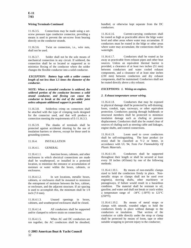
E-11 7/03
© 2003 American Boat & Yacht Council 32
Wiring Terminals-Continued 11.16.3.5. Connections may be made using a set-screw pressure type conductor connector, providing a means is used to prevent the set-screw from bearing directly on the conductor strands. 11.16.3.6. Twist on connectors, i.e., wire nuts, shall not be used.
11.16.3.7. Solder shall not be the sole means of mechanical connection in any circuit. If soldered, the connection shall be so located or supported as to minimize flexing of the conductor where the solder changes the flexible conductor into a solid conductor. EXCEPTION: Battery lugs with a solder contact length of not less than 1.5 times the diameter of the conductor. NOTE: When a stranded conductor is soldered, the soldered portion of the conductor becomes a solid strand conductor, and flexing can cause the conductor to break at the end of the solder joint unless adequate additional support is provided. 11.16.3.8. Solderless crimp on connectors shall be attached with the type of crimping tools designed for the connector used, and that will produce a connection meeting the requirements of E-11.16.3.3.
11.16.3.9. The shanks of terminals shall be protected against accidental shorting by the use of insulation barriers or sleeves, except for those used in grounding systems.
11.16.4. INSTALLATION 11.16.4.1. GENERAL 11.16.4.1.1. Junction boxes, cabinets, and other enclosures in which electrical connections are made shall be weatherproof, or installed in a protected location, to minimize the entrance or accumulation of moisture or water within the boxes, cabinets, or enclosures. 11.16.4.1.2. In wet locations, metallic boxes, cabinets, or enclosures shall be mounted to minimize the entrapment of moisture between the box, cabinet, or enclosure, and the adjacent structure. If air spacing is used to accomplish this, the minimum shall be 1/4 inch (7.0 mm). 11.16.4.1.3. Unused openings in boxes, cabinets, and weatherproof enclosures shall be closed. 11.16.4.1.4. All conductors shall be supported and/or clamped to relieve strain on connections. 11.16.4.1.5. When AC and DC conductors are run together, the AC conductors shall be sheathed,
bundled, or otherwise kept separate from the DC conductors. 11.16.4.1.6. Current-carrying conductors shall be routed as high as practicable above the bilge water level and other areas where water may accumulate. If conductors must be routed in the bilge or other areas where water may accumulate, the connections shall be watertight. 11.16.4.1.7. Conductors shall be routed as far away as practicable from exhaust pipes and other heat sources. Unless an equivalent thermal barrier is provided, a clearance of at least two inches (51 mm) between conductors and water cooled exhaust components, and a clearance of at least nine inches (230 mm) between conductors and dry exhaust components, shall be maintained. Conductors shall not be routed directly above a dry exhaust. EXCEPTIONS: 1. Wiring on engines.
2. Exhaust temperature sensor wiring. 11.16.4.1.8. Conductors that may be exposed to physical damage shall be protected by self-draining; loom, conduit, tape, raceways, or other equivalent protection. Conductors passing through bulkheads or structural members shall be protected to minimize insulation damage such as chafing or pressure displacement. Conductors shall also be routed clear of sources of chafing such as steering cable and linkages, engine shafts, and control connections. 11.16.4.1.9. Loom used to cover conductors shall be self-extinguishing. The base product (or resin) shall be classified as V-2 or better, in accordance with UL 94, Tests For Flammability Of Plastic Materials. 11.16.4.1.10. Conductors shall be supported throughout their length or shall be secured at least every 18 inches (455mm) by one of the following methods: 11.16.4.1.10.1. By means of non-metallic clamps sized to hold the conductors firmly in place. Non-metallic straps or clamps shall not be used over engine(s), moving shafts, other machinery or passageways, if failure would result in a hazardous condition. The material shall be resistant to oil, gasoline, and water and shall not break or crack within a temperature range of -34°C (-30°F) to 121°C (250°F); 11.16.4.1.10.2. By means of metal straps or clamps with smooth, rounded edges to hold the conductors firmly in place without damage to the conductors or insulation. That section of the conductor or cable directly under the strap or clamp shall be protected by means of loom, tape or other suitable wrapping to prevent injury to the conductor;

E-11 7/03
© 2003 American Boat & Yacht Council 33
Installation - General -Continued 11.16.4.1.10.3. By means of metal clamps lined with an insulating material resistant to the effects of oil, gasoline, and water. EXCEPTIONS: Exception to E-11.16.4.1.10: 1. Battery cables within 36 inches (910mm) of a battery terminal. 2. Cables attached to outboard motors. 11.16.4.1.11. No more than four conductors shall be secured to any one terminal stud. If additional connections are necessary, two or more terminal studs shall be connected together by means of jumpers or copper straps. 11.16.4.1.12. Ring and captive spade type terminal connectors shall be the same nominal size as the stud. 11.16.4.1.13. Conductors terminating at panelboards in junction boxes or fixtures shall be arranged to provide a length of conductor to relieve tension, to allow for repairs and to permit multiple conductors to be fanned at terminal studs. 11.16.4.2. DC SYSTEMS
11.16.4.2.1. Wiring shall be installed in a manner that will avoid magnetic loops in the area of the compass and magnetically sensitive devices. Direct current wires that may create magnetic fields in this area shall run in twisted pairs.
11.16.4.2.2. Battery cables without overcurrent protection shall comply with the following:
11.16.4.2.2.1. Battery cables shall be routed above normal bilge water levels throughout their length;
11.16.4.2.2.2. Battery cables shall be routed to avoid contact with metallic fuel system components;
11.16.4.2.2.3. The ungrounded battery cable shall be routed to avoid contact with any part of the engine or drive train. 11.16.4.3. FOR AC SYSTEMS 11.16.4.3.1. All connections normally carrying current shall be made in enclosures to protect against shock hazards. 11.16.4.3.2. Nonmetallic outlet boxes, flush device boxes and covers shall meet the requirements of UL 514C, Non-metallic Outlet Boxes, Flush Device Boxes and Covers.
11.17. APPLIANCES AND EQUIPMENT 11.17.1. GENERAL
11.17.1.1. All electrical appliances and equipment designed for permanent installation shall be securely mounted to the boat's structure. 11.17.2. FOR DC SYSTEMS
11.17.2.1. Appliances and fixed DC electrical equipment shall be designed so that the current carrying parts of the device are insulated from all exposed electrically conductive parts.
EXCEPTIONS: 1. 12-volt equipment not located in machinery spaces, not in contact with bilge, and not in contact with a fuel line. 2. Communications and audio equipment 3. Electric navigation equipment 4. Instruments and instrument clusters 5. Liquid level gauge transmitters. For installation of fuel tank transmitters on conductive surfaces. (See E-11.17.2.4.) 6. Navigation lights operating at nominal 12 volts. See ABYC A-16, “Electric Navigation Lights.” 7. Auxiliary generator sets 8. Engine mounted equipment. (See E-11.5.2.1.) 11.17.2.2. Devices subject to exceptions 1 through 8 in E-11.17.2.1 shall be installed with the case negative, and the positive connection shall be identified. 11.17.2.3. All exposed electrically conductive non-current carrying parts of fixed DC electrical equipment, and appliances that may normally be in contact with bilge water or seawater, shall be connected to the DC grounding system. EXCEPTIONS: 1. Boats not equipped with a DC grounding system. 2. Equipment with an effective double insulation system. 3. Metal parts isolated in non-conductive material 4. Electric trolling motors 11.17.2.4. Grounded Liquid Level Gauge Transmitters (senders) - Grounded liquid level gauge

E-11 7/03
© 2003 American Boat & Yacht Council 34
Appliances and Equipment – DC – Continued transmitters mounted on fuel tanks or tank plates shall have the transmitter negative return conductor connected directly to the DC main negative bus, the engine negative terminal, or for outboard boats the battery negative terminal or its bus. No other device shall be connected to this conductor. This conductor shall also serve as the static ground and/or the bonding conductor for the tank and fill. If a fuel tank is included in the lightning protection system the conductor between the fuel tank and the DC main negative bus shall meet the requirements of ABYC E-4, Lightning Protection.
11.17.3. FOR AC SYSTEMS 11.17.3.1. Fixed AC electrical equipment used on boats shall be designed so that the current carrying parts of the device are effectively insulated from all exposed electrically conductive parts. 11.17.3.2. All exposed, electrically conductive, non-current carrying parts of fixed AC electrical equipment and appliances intended to be grounded shall be connected to the grounding conductor. NOTE: If an appliance( e.g., electric range, electric dryer) has a neutral to ground bonding strap, it must be removed in order to comply with 11.5.3.2. 11.17.3.3. Integral overcurrent protection may be provided.
11.18. DC GROUNDING AND BONDING 11.18.1. DC Grounding - If a DC grounding system is installed, the DC grounding conductor shall be used to connect metallic non-current-carrying parts of those direct current devices identified in E-11.17.2.3 to the engine negative terminal or its bus for the purpose of minimizing stray current corrosion. (See FIGURE 18.) 11.18.2. DC Grounding Conductor
11.18.2.1. A DC grounding conductor shall not be smaller than one size under that required for current carrying conductors supplying the device and not less than 16 AWG. (See FIGURE 18 and FIGURE 19.)
11.18.2.2. Routing - The DC grounding conductor shall be routed from the device to the engine negative terminal or the DC main negative bus by one of the following means:
11.18.2.2.1. The DC grounding conductor shall be routed together with the current carrying conductors as a third wire;
11.18.2.2.2. The DC grounding conductor shall be routed as a separate conductor.
11.18.2.3. The DC grounding conductor shall be connected to a DC grounding bus in accordance with E-11.18.2.5.
11.18.2.4. Connections - DC grounding conductor connections shall be made in accordance with E-11.16.3.
11.18.2.5. DC Grounding Bus
11.18.2.5.1. The DC grounding bus shall be connected directly to the engine negative terminal or the DC main negative bus. 11.18.2.5.2. The DC grounding bus serving more than one electrical device shall comply with E-11.18.2 for the largest device, and shall be manufactured and installed in accordance with the following:
11.18.2.5.2.1. If the DC grounding bus is fabricated from copper or bronze strip, it shall have a thickness not less than 1/32 inch (0.8mm) and a width of not less than 1/2 inch (13mm); and 11.18.2.5.2.1.1. shall be drilled and tapped providing its thickness ensures no less than three full threads of engagement for the terminal screws; or
11.18.2.5.2.1.2. shall be through-drilled, and the connections made with machine screws and lock-nuts.
NOTE: Copper pipe may be used providing its wall thickness is sufficient for the pipe to be drilled and tapped as required above. 11.18.2.5.2.2. Copper braid shall not be used.
11.18.2.6. Combined DC Grounding and Bonding Systems - The DC grounding conductors may be combined with the following systems providing all the requirements with respect to conductor size are met for each system. (See FIGURE 18, FIGURE 19 and FIGURE 20 ) 11.18.2.6.1. Lightning Protection - See ABYC E-4, Lightning Protection.
11.18.2.6.2. Cathodic Bonding - See ABYC E-2, Cathodic Protection.
11.18.2.6.3. Static Electricity Grounding – See E-11.17.2.4, ABYC H-24, Gasoline Fuel Systems, and ABYC H-33, Diesel Fuel Systems.

E-11 7/03
© 2003 American Boat & Yacht Council 35
Grounding and Bonding – DC – Continued 11.18.2.7. Radio Ground Plate - If the radio ground plate is connected to the engine negative terminal, the connecting conductor shall meet the requirements of ABYC E-4, Lightning Protection, since a radio ground plate may also function as a lightning ground plate.
11.18.2.8. Coaxial Cables and Conduit - The metallic braid of coaxial cables and metal conduit used for radio interference, or any form of radio shielding or armoring, shall be connected to earth ground with an insulated stranded copper conductor.
Figure 1- ISOLATION OF ELECTRICAL COMPONENTS

E-11 7/03
© 2003 American Boat & Yacht Council 36
Figure 2 – ISOLATION OF ELECTRICAL COMPONENTS
Figure 3 – ISOLATION OF ELECTRICAL COMPONENTS

E-11 7/03
© 2003 American Boat & Yacht Council 37
Figure 4 – ISOLATION OF ELECTRICAL COMPONENTS
Figure 5 – ISOLATION OF ELECTRICAL COMPONENTS
Figure 6 – ISOLATION OF ELECTRICAL COMPONENTS

E-11 7/03
© 2003 American Boat & Yacht Council 38
Figure 7 – ISOLATION BULKHEAD REQUIREMENTS
Figure 8 – BULKHEADS

E-11 7/03
© 2003 American Boat & Yacht Council 39
Figures 9 A and 9 B – TYPICAL OUTBOARD DC SYSTEM 9A NOTES: 1. For location of overcurrent protection device (See E-11.12.1) 2. This diagram does not illustrate a complete system. Refer to appropriate text.

E-11 7/03
© 2003 American Boat & Yacht Council 40
9 B NOTES: 1. For location of overcurrent protection device (See E-11.12.1) 2. This diagram does not illustrate a complete system. Refer to appropriate text.

E-11 7/03
© 2003 American Boat & Yacht Council 41
FIGURES 10 A AND 10 B – TYPCAL INBOARD DC SYSTEM WITHOUT AN AC ELECTRICAL SYSTEM 10 A NOTES: 1. For location of overcurrent protection device (See E- 11.12.1) 2. This diagram does not illustrate a complete system. Refer to appropriate text.

E-11 7/03
© 2003 American Boat & Yacht Council 42
10 B NOTES: 1. For location of overcurrent protection device (See E-11.12.1) 2. This diagram does not illustrate a complete system. Refer to appropriate text.

E-11 7/03
© 2003 American Boat & Yacht Council 43
FIGURE 11 – MAIN AND BRANCH CIRCUIT PROTECTION NOTE: This diagram does not illustrate a complete system. Refer to appropriate text.
FIGURE 12 – STANDARD CONVENIENCE RECEPTACLE CONFIGURATION
FIGURE 13 – SHORE POWER CABLE CONFIGURATIONS

E-11 7/03
© 2003 American Boat & Yacht Council 44
FIGURE 14 – SHORE POWER CABLE CONFIGURATIONS, PIN AND SLEEVE
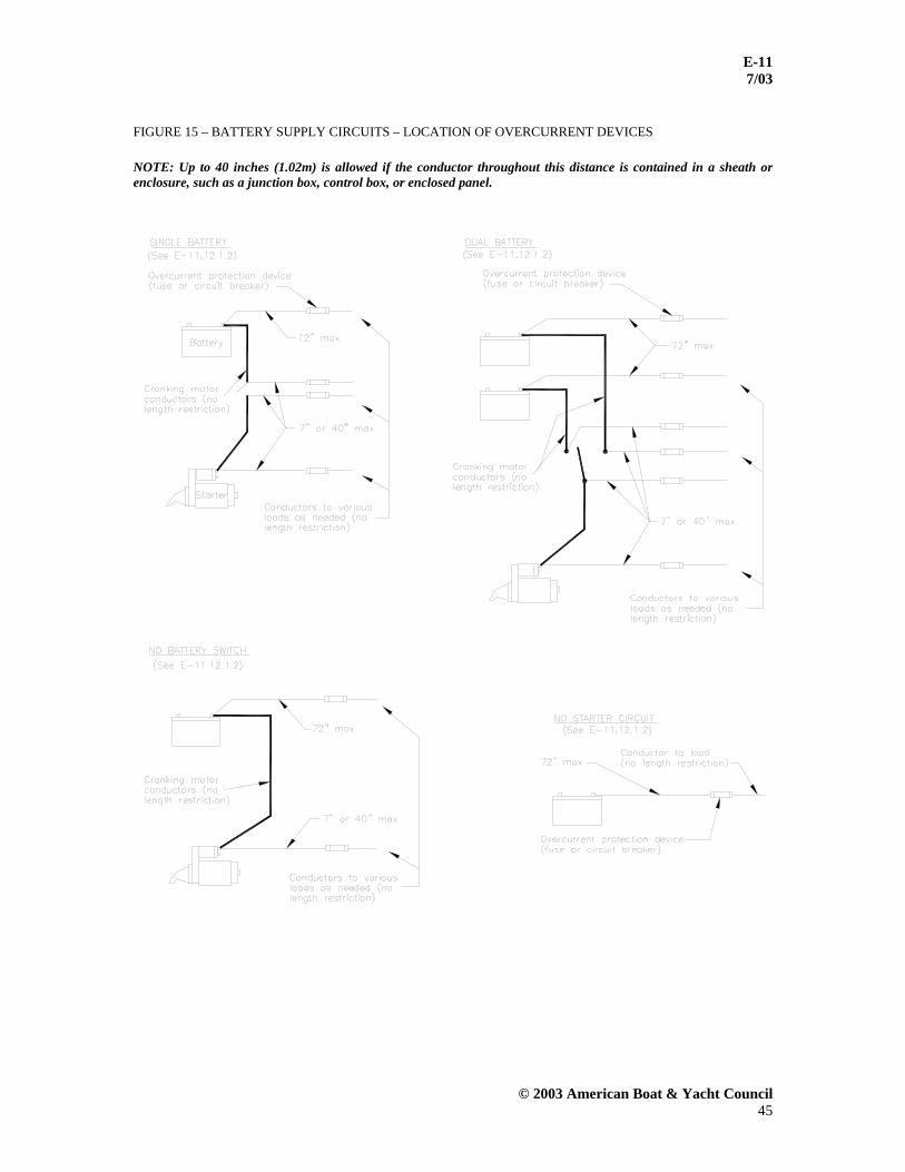
E-11 7/03
© 2003 American Boat & Yacht Council 45
FIGURE 15 – BATTERY SUPPLY CIRCUITS – LOCATION OF OVERCURRENT DEVICES NOTE: Up to 40 inches (1.02m) is allowed if the conductor throughout this distance is contained in a sheath or enclosure, such as a junction box, control box, or enclosed panel.

E-11 7/03
© 2003 American Boat & Yacht Council 46
FIGURE 16 – PANELBOARDS AND SWITCHBOARDS
FIGURE 17 – SOME TYPICAL TYPES OF TERMINALS

E-11 7/03
© 2003 American Boat & Yacht Council 47
FIGURE 18 – DC NEGATIVE SYSTEM – DC GROUNDING SYSTEM (TYPICAL INBOARD DC SYSTEM) NOTES: 1. Cathodic bonding – refer to ABYC E-2, “Cathodic Protection” 2. Lightning bonding – refer to ABYC E-4 “Lightning Protection” 3. For location of overcurrent protection device refer to ABYC E-11.12.1
4. This diagram does not illustrate a complete system. Refer to the appropriate text.

E-11 7/03
© 2003 American Boat & Yacht Council 48
FIGURE 19 – DC COMMON GROUNDING SYSTEM
FIGURE 20 - COMBINED LIGHTNING/DC GROUNDING SYSTEM NOTE: Lightning protection requires conductivity to ground of not less than that of a 4 AWG copper conductor. See ABYC E-4, “Lightning Protection”

E-11 7/03
© 2003 American Boat & Yacht Council 49
TABLE III – FREE STANDING RANGE RATINGS NAMEPLATE RATING USE (WATTS) (WATTS) 10,000 or less 80% of rating 10,001 – 12,500 8,000 12,501 – 13,500 8,400 13,501 – 14,500 8,800 14,501 – 15,500 9,200 15,501 – 16,500 9,600 16,501 – 17,500 10,000 NOTE: Ratings are for free standing ranges as distinguished from separate oven and cooking units.
TABLE IV – ALLOWABLE AMPERAGE FOR SYSTEMS UNDER 50 VOLTS
Temperature Rating of Conductor Insulation
CONDUCTOR SIZE
60° C
(140° F)
75° C
(167° F)
80° C
(176° F)
90° C
(194° F)
105° C
(221° F)
125° C
(257° F)
200° C
(392° F) ENGLISH
(METRIC) SEE TABLE VIII
OUTSIDE ENGINE SPACES
INSIDE ENGINE SPACES
OUTSIDE ENGINE SPACES
INSIDE ENGINE SPACES
OUTSIDE ENGINE SPACES
INSIDE ENGINE SPACES
OUTSIDE ENGINE SPACES
INSIDE ENGINE SPACES
OUTSIDE ENGINE SPACES
INSIDE ENGINE SPACES
OUTSIDE ENGINE SPACES
INSIDE ENGINE SPACES
OUTSIDE OR INSIDE ENGINE
SPACES
18 (0.8) 10 5.8 10 7.5 15 11.7 20 16.4 20 17.0 25 22.3 25 16 (1) 15 8.7 15 11.3 20 15.6 25 20.5 25 21.3 30 25.7 35 14 (2) 20 11.6 20 15.0 25 19.5 30 24.6 35 29.8 40 35.6 45 12 (3) 25 14.5 25 18.8 35 27.3 40 32.8 45 38.3 50 44.5 55 10 (5) 40 23.2 40 30.0 50 39.0 55 45.1 60 51.0 70 62.3 70 8 (8) 55 31.9 65 48.8 70 54.6 70 57.4 80 68.0 90 80.1 100 6 (13) 80 46.4 95 71.3 100 78.0 100 82.0 120 102 125 111 135 4 (19) 105 60.9 125 93.8 130 101 135 110 160 136 170 151 180 2 (32) 140 81.2 170 127 175 138 180 147 210 178 225 200 240 1 (40) 165 95.7 195 146 210 163 210 172 245 208 265 235 280 0 (50) 195 113 230 172 245 191 245 200 285 242 305 271 325
00 (62) 225 130 265 198 285 222 285 233 330 280 355 316 370 000 (81) 260 150 310 232 330 257 330 270 385 327 410 384 430
0000 (103) 300 174 380 270 385 300 385 315 445 378 475 422 510 NOTE: Cross reference with voltage drop tables and formula in E-11.16.1.2.9., Note 2.
TABLE V - A – CIRCUIT BREAKER MINIMUM AMPERE INTERRUPTING CAPACITY FOR SYSTEMS UNDER 50 VOLTS
Ampere Interrupting Capacity (AIC) (amperage available at circuit breaker terminals)
Total Connected Battery (Cold Cranking Amperes)
Main Circuit Breaker (Amperes) *See Note
Branch Circuit Breaker (Amperes) *See Note
12 Volts 650 or less 1500 750 and 651-1100 3000 1500 24 Volts over 1100 5000 2500 32 Volts 1250 or less 3000 1500 over 1250 5000 2500

E-11 7/03
© 2003 American Boat & Yacht Council 50
*NOTE: The main circuit breaker(s) shall be considered to be the first breaker(s) in a circuit connected in series with the battery. All subsequent breakers, including sub-main breakers, connected in series with a main circuit breaker shall be considered to be “branch circuit breakers.” (See FIGURE 16 .)
TABLE V - B – CIRCUIT BREAKER INTERRUPTING CAPACITY FOR SYSTEM OVER 50 VOLT
SHORE POWER
SOURCE
MAIN SHORE POWER
DISCONNECT CIRCUIT BREAKER
BRANCH BREAKER
120V – 30A 3000 3000 120V – 50A 3000 3000
120/240V – 50A 5000 3000 240V – 50A 5000 3000
120/208V – 3 phase/WYE – 30A 5000 3000 120/240V – 100A 5000 3000
120/208V – 3 phase/WYE – 100A 5000 3000 NOTES: 1. The main circuit breaker shall be considered to be the first circuit breaker connected to a source of AC power. All subsequent breakers, including sub-main breakers connected in series with a main circuit breaker, shall be considered to be branch circuit breakers. 2. A fuse in series with, and ahead of, a circuit breaker may be required by the circuit breaker manufacturer to achieve the interrupting capacity in TABLE V - B .
TABLE VI – SAE CONDUCTORS SAE CONDUCTORS TYPE
DESCRIPTION
AVAILABLE INSULATION TEMPERATURE RATING PER SAE J378
GPT Thermoplastic Insulation, Braidless 60° C (140° F), 90° C (194° F), 105° C (221° F) HDT Thermoplastic Insulation, Braidless 60° C (140° F), 90° C (194° F), 105° C (221° F) SGT Thermoplastic Insulation, Braidless 60° C (140° F), 90° C (194° F), 105° C (221° F) STS Thermosetting Synthetic Rubber Insulation, Braidless 85° C (185° F), 90° C (194 ° F) HTS Thermosetting Synthetic Rubber Insulation, Braidless 85° C (185° F), 90° C (194° F) SXL Thermosetting Cross Linked Polyethylene Insulation, Braidless 125° C (257° F)

E-11 7/03
© 2003 American Boat & Yacht Council 51
TABLE VII – A – ALLOWABLE AMPERAGE OF CONDUCTORS WHEN NO MORE THAN TWO CURRENT CARRYING CONDUCTORS ARE BUNDLED
TEMPERATURE RATING OF CONDUCTOR INSULATION CONDUCTOR
60°C (140°F)
75°C (167°F)
80°C (176°F)
90°C (194°F)
105°C (221°F)
125°C (257°F)
200°C (392°
F) SIZE
(AWG)
OUTSIDE ENGINE SPACES
INSIDE ENGINE SPACES
OUTSIDE ENGINE SPACES
INSIDE ENGINE SPACES
OUTSIDE ENGINE SPACES
INSIDE ENGINE SPACES
OUTSIDE ENGINE SPACES
INSIDE ENGINE SPACES
OUTSIDE ENGINE SPACES
INSIDE ENGINE SPACES
OUTSIDE ENGINE SPACES
INSIDE ENGINE SPACES
OUTSIDE OR
INSIDE ENGINE SPACES
18 10 5.8 10 7.5 15 11.7 20 16.4 20 17.0 25 22.3 25 16 15 8.7 15 11.3 20 15.6 25 20.5 25 21.3 30 26.7 35 14 20 11.6 20 15.0 25 19.5 30 24.6 35 29.8 40 35.6 45 12 25 14.5 25 18.8 35 27.3 40 32.8 45 38.3 50 44.5 55 10 40 23.2 40 30.0 50 39.0 55 45.1 60 51.0 70 62.3 70 8 55 31.9 65 48.8 70 54.6 70 57.4 80 68.0 90 80.1 100 6 80 46.4 95 71.3 100 78.0 100 82.0 120 102.0 125 111.3 135 4 105 60.9 125 93.8 130 101.4 135 110.7 160 136.0 170 151.3 180 3 120 69.6 145 108.8 150 117.0 155 127.1 180 153.0 195 173.6 210 2 140 81.2 170 127.5 175 136.5 180 147.6 210 178.5 225 200.3 240 1 165 95.7 195 146.3 210 163.8 210 172.2 245 208.3 265 235.9 280 0 195 113.1 230 172.5 245 191.1 245 200.9 285 242.3 305 271.5 325
00 225 130.5 265 198.8 285 222.3 285 233.7 330 280.5 355 316.0 370 000 260 150.8 310 232.5 330 257.4 330 270.6 385 327.3 410 364.9 430
0000 300 174.0 360 270.0 385 300.3 385 315.7 445 378.3 475 422.8 510
TABLE VII – B – ALLOWABLE AMPERAGE OF CONDUCTORS WHEN THREE CURRENT CARRYING CONDUCTORS ARE BUNDLED
TEMPERATURE RATING OF CONDUCTOR INSULATION CONDUCTOR
60°C (140°F)
75°C (167°F)
80°C (176°F)
90°C (194°F)
105°C (221°F)
125°C (257°F)
200°C (392°F)
SIZE (AWG)
OUTSIDE ENGINE SPACES
INSIDE ENGINE SPACES
OUTSIDE ENGINE SPACES
INSIDE ENGINE SPACES
OUTSIDE ENGINE SPACES
INSIDE ENGINE SPACES
OUTSIDE ENGINE SPACES
INSIDE ENGINE SPACES
OUTSIDE ENGINE SPACES
INSIDE ENGINE SPACES
OUTSIDE ENGINE SPACES
INSIDE ENGINE SPACES
OUTSIDE OR INSIDE ENGINE SPACES
18 7.0 4.1 7.0 5.3 10.5 8.2 14.0 11.5 14.0 11.9 17.5 15.6 17.5 16 10.5 6.1 10.5 7.9 14.0 10.9 17.5 14.4 17.5 14.9 21.0 18.7 24.5 14 14.0 8.1 14.0 10.5 17.5 13.7 21.0 17.2 24.5 20.8 28.0 24.9 31.5 12 17.5 10.2 17.5 13.1 24.5 19.1 28.0 23.0 31.5 26.8 35.0 31.2 38.5 10 28.0 16.2 28.0 21.0 35.0 27.3 38.5 31.6 42.0 35.7 49.0 43.6 49.0 8 38.5 22.3 45.5 34.1 49.0 38.2 49.0 40.2 56.0 47.6 63.0 56.1 70.0 6 56.0 32.5 66.5 49.9 70.0 54.6 70.0 57.4 84.0 71.4 87.5 77.9 94.5 4 73.5 42.6 87.5 65.6 91.0 71.0 94.5 77.5 112.0 95.2 119.0 105.9 126.0 3 84.0 48.7 101.5 76.1 105.0 81.9 108.5 89.0 126.0 107.1 136.5 121.5 147.0 2 98.0 56.8 119.0 89.3 122.5 95.6 126.0 103.3 147.0 125.0 157.5 140.2 168.0 1 115.5 67.0 136.5 102.4 147.0 114.7 147.0 120.5 171.5 145.8 185.5 165.1 196.0 0 136.5 79.2 161.0 120.8 171.5 133.8 171.5 140.6 199.5 169.6 213.5 190.0 227.5
00 157.5 91.4 185.5 139.1 199.5 155.6 199.5 163.6 231.0 196.4 248.5 221.2 259.0 000 182.0 105.6 217.0 162.8 231.0 180.2 231.0 189.4 269.5 229.1 287.0 255.4 301.0
0000 210.0 121.8 252.0 189.0 269.5 210.2 269.5 221.0 311.5 264.8 332.5 295.9 357.0

E-11 7/03
© 2003 American Boat & Yacht Council 52
TABLE VII – C – ALLOWABLE AMPERAGE OF CONDUCTORS WHEN FOUR TO SIX CURRENT CARRYING CONDUCTORS ARE BUNDLED
TEMPERATURE RATING OF CONDUCTOR INSULATION
CONDUCTOR 60°C
(140°F) 75°C
(167°F) 80°C
(176°F) 90°C
(194°F) 105°C
(221°F) 125°C
(257°F) 200°C (392°F)
SIZE (AWG)
OUTSIDE ENGINE SPACES
INSIDE ENGINE SPACES
OUTSIDE ENGINE SPACES
INSIDE ENGINE SPACES
OUTSIDE ENGINE SPACES
INSIDE ENGINE SPACES
OUTSIDE ENGINE SPACES
INSIDE ENGINE SPACES
OUTSIDE ENGINE SPACES
INSIDE ENGINE SPACES
OUTSIDE ENGINE SPACES
INSIDE ENGINE SPACES
OUTSIDE OR INSIDE ENGINE SPACES
18 6.0 3.5 6.0 4.5 9.0 7.0 12.0 9.8 12.0 10.2 15.0 13.4 15.0 16 9.0 5.2 9.0 6.8 12.0 9.4 15.0 12.3 15.0 12.8 18.0 16.0 21.0 14 12.0 7.0 12.0 9.0 15.0 11.7 18.0 14.8 21.0 17.9 24.0 21.4 27.0 12 15.0 8.7 15.0 11.3 21.0 16.4 24.0 19.7 27.0 23.0 30.0 26.7 33.0 10 24.0 13.9 24.0 18.0 30.0 23.4 33.0 27.1 36.0 30.6 42.0 37.4 42.0 8 33.0 19.1 39.0 29.3 42.0 32.8 42.0 34.4 48.0 40.8 54.0 48.1 60.0 6 48.0 27.8 57.0 42.8 60.0 46.8 60.0 49.2 72.0 61.2 75.0 66.8 81.0 4 63.0 36.5 75.0 56.3 78.0 60.8 81.0 66.4 96.0 81.6 102.0 90.8 108.0 3 72.0 41.8 87.0 65.3 90.0 70.2 93.0 76.3 108.0 91.8 117.0 104.1 126.0 2 84.0 48.7 102.0 76.5 105.0 81.9 108.0 88.6 126.0 107.1 135.0 120.2 144.0 1 99.0 57.4 117.0 87.8 126.0 98.3 126.0 103.3 147.0 125.0 159.0 141.5 168.0 0 117.0 67.9 138.0 103.5 147.0 114.7 147.0 120.5 171.0 145.4 183.0 162.9 195.0
00 135.0 78.3 159.0 119.3 171.0 133.4 171.0 140.2 198.0 168.3 213.0 189.6 222.0 000 156.0 90.5 186.0 139.5 198.0 154.4 198.0 162.4 231.0 196.4 246.0 218.9 258.0
0000 180.0 104.4 216.0 162.0 231.0 180.2 231.0 189.4 267.0 227.0 285.0 253.7 306.0
TABLE VII – D – ALLOWABLE AMPERAGE OF CONDUCTORS WHEN SEVEN TO 24 CURRENT CARRYING CONDUCTORS ARE BUNDLED
TEMPERATURE RATING OF CONDUCTOR INSULATION CONDUCTOR
60°C (140°F)
75°C (167°F)
80°C (176°F)
90°C (194°F)
105°C (221°F)
125°C (257°F)
200°C (392°F)
SIZE (AWG)
OUTSIDE ENGINE SPACES
INSIDE ENGINE SPACES
OUTSIDE ENGINE SPACES
INSIDE ENGINE SPACES
OUTSIDE ENGINE SPACES
INSIDE ENGINE SPACES
OUTSIDE ENGINE SPACES
INSIDE ENGINE SPACES
OUTSIDE ENGINE SPACES
INSIDE ENGINE SPACES
OUTSIDE ENGINE SPACES
INSIDE ENGINE SPACES
OUTSIDE OR INSIDE ENGINE SPACES
18 5.0 2.9 5.0 3.8 7.5 5.9 10.0 8.2 10.0 8.5 12.5 11.1 12.5 16 7.5 4.4 7.5 5.6 10.0 7.8 12.5 10.3 12.5 10.6 15.0 13.4 17.5 14 10.0 5.8 10.0 7.5 12.5 9.8 15.0 12.3 17.5 14.9 20.0 17.8 22.5 12 12.5 7.3 12.5 9.4 17.5 13.7 20.0 16.4 22.5 19.1 25.0 22.3 27.5 10 20.0 11.6 20.0 15.0 25.0 19.5 27.5 22.6 30.0 25.5 35.0 31.2 35.0 8 27.5 16.0 32.5 24.4 35.0 27.3 35.0 28.7 40.0 34.0 45.0 40.1 50.0 6 40.0 23.2 47.5 35.6 50.0 39.0 50.0 41.0 60.0 51.0 62.5 55.6 67.5 4 52.5 30.5 62.5 46.9 65.0 50.7 67.5 55.4 80.0 68.0 85.0 75.7 90.0 3 60.0 34.8 72.5 54.4 75.0 58.5 77.5 63.6 90.0 76.5 97.5 86.8 105.0 2 70.0 40.6 85.0 63.8 87.5 68.3 90.0 73.8 105.0 89.3 112.5 100.1 120.0 1 82.5 47.9 97.5 73.1 105.0 81.9 105.0 86.1 122.5 104.1 132.5 117.9 140.0 0 97.5 56.6 115.0 86.3 122.5 95.6 122.5 100.5 142.5 121.1 152.5 135.7 162.5
00 112.5 65.3 132.5 99.4 142.5 111.2 142.5 116.9 165.0 140.3 177.5 158.0 185.0 000 130.0 75.4 155.0 116.3 165.0 128.7 165.0 135.3 192.5 163.6 205.0 182.5 215.0
0000 150.0 87.0 180.0 135.0 192.5 150.2 192.5 157.9 222.5 189.1 237.5 211.4 255.0

E-11 7/03
© 2003 American Boat & Yacht Council 53
TABLE VII – E - ALLOWABLE AMPERAGE OF CONDUCTORS WHEN 25 OR MORE CURRENT CARRYING CONDUCTORS ARE BUNDLED
TEMPERATURE RATING OF CONDUCTOR INSULATION
CONDUCTOR
60°C (140°F)
75°C (167°F)
80°C (176°F)
90°C (194°F)
105°C (221°F)
125°C (257°F)
200°C (392°F)
SIZE (AWG)
OUTSIDE ENGINE SPACES
INSIDE ENGINE SPACES
OUTSIDE ENGINE SPACES
INSIDE ENGINE SPACES
OUTSIDE ENGINE SPACES
INSIDE ENGINE SPACES
OUTSIDE ENGINE SPACES
INSIDE ENGINE SPACES
OUTSIDE ENGINE SPACES
INSIDE ENGINE SPACES
OUTSIDE ENGINE SPACES
INSIDE ENGINE SPACES
OUTSIDE OR INSIDE ENGINE SPACES
18 4.0 2.3 4.0 3.0 6.0 4.7 8.0 6.6 8.0 6.8 10.0 8.9 10.0 16 6.0 3.5 6.0 4.5 8.0 6.2 10.0 8.2 10.0 8.5 12.0 10.7 14.0 14 8.0 4.6 8.0 6.0 10.0 7.8 12.0 9.8 14.0 11.9 16.0 14.2 18.0 12 10.0 5.8 10.0 7.5 14.0 10.9 16.0 13.1 18.0 15.3 20.0 17.8 22.0 10 16.0 9.3 16.0 12.0 20.0 15.6 22.0 18.0 24.0 20.4 28.0 24.9 28.0 8 22.0 12.8 26.0 19.5 28.0 21.8 28.0 23.0 32.0 27.2 36.0 32.0 40.0 6 32.0 18.6 38.0 28.5 40.0 31.2 40.0 32.8 48.0 40.8 50.0 44.5 54.0 4 42.0 24.4 50.0 37.5 52.0 40.6 54.0 44.3 64.0 54.4 68.0 60.5 72.0 3 48.0 27.8 58.0 43.5 60.0 46.8 62.0 50.8 72.0 61.2 78.0 69.4 84.0 2 56.0 32.5 68.0 51.0 70.0 54.6 72.0 59.0 84.0 71.4 90.0 80.1 96.0 1 66.0 38.3 78.0 58.5 84.0 65.5 84.0 68.9 98.0 83.3 106.0 94.3 112.0 0 78.0 45.2 92.0 69.0 98.0 76.4 98.0 80.4 114.0 96.9 122.0 108.6 130.0
00 90.0 52.2 106.0 79.5 114.0 88.9 114.0 93.5 132.0 112.2 142.0 126.4 148.0 000 104.0 60.3 124.0 93.0 132.0 103.0 132.0 108.2 154.0 130.9 164.0 146.0 172.0
0000 120.0 69.6 144.0 108.0 154.0 120.1 154.0 126.3 178.0 151.3 190.0 169.1 204.0
TABLE VIII - FLEXIBLE CORDS Table VIII A FLEXIBLE CORDS TYPE DESCRIPTION AVAILABLE INSULATION TEMPERATURE
RATING SO, SOW Hard Service Cord, Oil Resistant Compound 60°C (140° F), 75°C (167°F) & higher ST, STW Hard Service Cord, Thermoplastic 60°C (140° F), 75°C (167°F) & higher STO, STOW,SEO, SEOW
Hard Service Cord, Oil Resistant Thermoplastic 60°C (140° F), 75°C (167°F) & higher
SJO, SJOW Junior Hard Service Cord, Oil Resistant Compound 60°C (140°F), 75°C (167°F) & higher SJT, SJTW Junior Hard Service Cord, Thermoplastic 60°C (140°F), 75°C (167°F) & higher SJTO, SJTOW
Junior Hard Service Cord, Oil Resistant Thermoplastic 60°C (140°F), 75°C (167°F) & higher

E-11 7/03
© 2003 American Boat & Yacht Council 54
Table VIII B (SEE E-11.16.1.1.1 AND E-11.16.1.3.4)
TYPE
DAMP LOCATION
OIL RESISTANT
COVER
EXTRA HARD USAGE
HARD USAGE
SE, SEW X X SEO, SEOW X X X
SJ, SJW X X SJE, SJEW X X
SJEO, SJEOW
X X X
SJO, SJOW X X X SJOO,
SJOOW X X X
SJT, SJTW X X SJTO,
SJTOW X X X
SJTOO, SJTOOW
X X X
SO, SOW X X X ST, STW X X
STO, STOW X X X STOO,
STOOW X X X
NOTES: 1. Available in the same temperature rating as flexible cords in Table VIII A 2 167°F (75°C) dry insulation is suitable for use inside machinery spaces. 3. 140°F (60°C) dry insulation is suitable only for use outside machinery spaces. 4. Oil resistant cover shall be used in machinery spaces.
TABLE IX – CONDUCTORS CONDUCTORS TYPES (SEE NOTE)
DESCRIPTION
AVAILABLE INSULATION TEMPERATURE RATING
THW Moisture and Heat-Resistant, Thermoplastic 75° C (167° F) TW Moisture-Resistant, Thermoplastic 60° C (140° F) HWN Moisture and Heat-Resistant, Thermoplastic 75° C (167° F) XHHW Moisture and Heat-Resistant, Cross Linked
Synthetic Polymer 90° C (194° F)
MTW Moisture, Heat and Oil Resistant, Thermoplastic 90° C (194° F) AWM Style Nos. 1230, Moisture, Heat and Oil Resistant,
1231-1232, 1275 Thermoplastic, Thermosetting 1344-1346
105° C (221° F)
UL 1426 Boat Cable (See UL 1426 Cables for Boats) NOTE: Some of the listed types are not commonly available in stranded construction for sizes smaller than 8 AWG.

E-11 7/03
© 2003 American Boat & Yacht Council 55
TABLE X – CONDUCTORS SIZED FOR 3 PERCENT DROP IN VOLTAGE NOTE: In the event of a conflict between the voltage drop table and the ampacity table, use the larger wire size.
Length of Conductor from Source of Current to Device and Back to Source - Feet 10 15 20 25 30 40 50 60 70 80 90 100 110 120 130 140 150 160 170 TOTAL CURRENT ON CIRCUIT IN AMPS.
12 Volts - 3% Drop Wire Sizes (gauge) - Based on Minimum CM Area
5 18 16 14 12 12 10 10 10 8 8 8 6 6 6 6 6 6 6 6 10 14 12 10 10 10 8 6 6 6 6 4 4 4 4 2 2 2 2 2 15 12 10 10 8 8 6 6 6 4 4 2 2 2 2 2 1 1 1 1 20 10 10 8 6 6 6 4 4 2 2 2 2 1 1 1 0 0 0 2/0 25 10 8 6 6 6 4 4 2 2 2 1 1 0 0 0 2/0 2/0 2/0 3/0 30 10 8 6 6 4 4 2 2 1 1 0 0 0 2/0 2/0 3/0 3/0 3/0 3/0 40 8 6 6 4 4 2 2 1 0 0 2/0 2/0 3/0 3/0 3/0 4/0 4/0 4/0 4/0 50 6 6 4 4 2 2 1 0 2/0 2/0 3/0 3/0 4/0 4/0 4/0 60 6 4 4 2 2 1 0 2/0 3/0 3/0 4/0 4/0 4/0 70 6 4 2 2 1 0 2/0 3/0 3/0 4/0 4/0 80 6 4 2 2 1 0 3/0 3/0 4/0 4/0 90 4 2 2 1 0 2/0 3/0 4/0 4/0 100 4 2 2 1 0 2/0 3/0 4/0 24 Volts - 3% Drop Wire Sizes (gauge) - Based on Minimum CM Area 5 18 18 18 16 16 14 12 12 12 10 10 10 10 10 8 8 8 8 8 10 18 16 14 12 12 10 10 10 8 8 8 6 6 6 6 6 6 6 6 15 16 14 12 12 10 10 8 8 6 6 6 6 6 4 4 4 4 4 2 20 14 12 10 10 10 8 6 6 6 6 4 4 4 4 2 2 2 2 2 25 12 12 10 10 8 6 6 6 4 4 4 4 2 2 2 2 2 2 1 30 12 10 10 8 8 6 6 4 4 4 2 2 2 2 2 1 1 1 1 40 10 10 8 6 6 6 4 4 2 2 2 2 1 1 1 0 0 0 2/0 50 10 8 6 6 6 4 4 2 2 2 1 1 0 0 0 2/0 2/0 2/0 3/0 60 10 8 6 6 4 4 2 2 1 1 0 0 0 2/0 2/0 3/0 3/0 3/0 3/0 70 8 6 6 4 4 2 2 1 1 0 0 2/0 2/0 3/0 3/0 3/0 3/0 4/0 4/0 80 8 6 6 4 4 2 2 1 0 0 2/0 2/0 3/0 3/0 3/0 4/0 4/0 4/0 4/0 90 8 6 4 4 2 2 1 0 0 2/0 2/0 3/0 3/0 4/0 4/0 4/0 4/0 4/0 100 6 6 4 4 2 2 1 0 2/0 2/0 3/0 3/0 4/0 4/0 4/0 32 Volts - 3% Drop Wire Sizes (gauge) - Based on Minimum CM Area 5 18 18 18 18 16 16 14 14 12 12 12 12 10 10 10 10 10 10 8 10 18 16 16 14 14 12 12 10 10 10 8 8 8 8 8 6 6 6 6 15 16 14 14 12 12 10 10 8 8 8 6 6 6 6 6 6 6 4 4 20 16 14 12 12 10 10 8 8 6 6 6 6 6 4 4 4 4 4 2 25 14 12 12 10 10 8 8 6 6 6 6 4 4 4 4 2 2 2 2 30 14 12 10 10 8 8 6 6 6 4 4 4 4 2 2 2 1 1 1 40 12 10 10 8 8 6 6 4 4 4 2 2 2 2 2 1 1 1 1 50 12 10 8 8 6 6 4 4 2 2 2 2 2 1 1 0 0 0 0 60 10 8 8 6 6 4 4 2 2 2 2 1 1 0 0 0 2/0 2/0 2/0 70 10 8 6 6 6 4 2 2 2 1 1 0 0 0 2/0 2/0 2/0 3/0 3/0 80 10 8 6 6 4 4 2 2 1 1 0 0 0 2/0 2/0 3/0 3/0 3/0 3/0 90 8 6 6 6 4 2 2 2 1 0 0 2/0 2/0 2/0 3/0 3/0 3/0 4/0 4/0 100 8 6 6 4 4 2 2 1 0 0 2/0 2/0 2/0 3/0 3/0 3/0 4/0 4/0 4/0

E-11 7/03
© 2003 American Boat & Yacht Council 56
TABLE XI CONDUCTORS SIZES FOR 10 % VOLTAGE DROP NOTE: In the event of a conflict between the voltage drop table and the ampacity table, use the larger wire size.
Length of Conductor from Source of Current to Device and Back to Source - Feet 10 15 20 25 30 40 50 60 70 80 90 100 110 120 130 140 150 160 170 TOTAL CURRENT ON CIRCUIT IN AMPS
12 Volts - 10% Drop Wire Sizes (gauge) - Based on Minimum CM Area
5 18 18 18 18 18 16 16 14 14 14 12 12 12 12 12 10 10 10 10 10 18 18 16 16 14 14 12 12 10 10 10 10 8 8 8 8 8 8 6 15 18 16 14 14 12 12 10 10 8 8 8 8 8 6 6 6 6 6 6 20 16 14 14 12 12 10 10 8 8 8 6 6 6 6 6 6 4 4 4 25 16 14 12 12 10 10 8 8 6 6 6 6 6 4 4 4 4 4 2 30 14 12 12 10 10 8 8 6 6 6 6 4 4 4 4 2 2 2 2 40 14 12 10 10 8 8 6 6 6 4 4 4 2 2 2 2 2 2 2 50 12 10 10 8 8 6 6 4 4 4 2 2 2 2 2 1 1 1 1 60 12 10 8 8 6 6 4 4 2 2 2 2 2 1 1 1 0 0 0 70 10 8 8 6 6 6 4 2 2 2 2 1 1 1 0 0 0 2/0 2/0 80 10 8 8 6 6 4 4 2 2 2 1 1 0 0 0 2/0 2/0 2/0 2/0 90 10 8 6 6 6 4 2 2 2 1 1 0 0 0 2/0 2/0 2/0 3/0 3/0 100 10 8 6 6 4 4 2 2 1 1 0 0 0 2/0 2/0 2/0 3/0 3/0 3/0 24 Volts - 10% Drop Wire Sizes (gauge) - Based on Minimum CM Area 5 18 18 18 18 18 18 18 18 16 16 16 16 14 14 14 14 14 14 12 10 18 18 18 18 18 16 16 14 14 14 12 12 12 12 12 10 10 10 10 15 18 18 18 16 16 14 14 12 12 12 10 10 10 10 10 8 8 8 8 20 18 18 16 16 14 14 12 12 10 10 10 10 8 8 8 8 8 8 6 25 18 16 16 14 14 12 12 10 10 10 8 8 8 8 8 6 6 6 6 30 18 16 14 14 12 12 10 10 8 8 8 8 8 6 6 6 6 6 6 40 16 14 14 12 12 10 10 8 8 8 6 6 6 6 6 6 4 4 4 50 16 14 12 12 10 10 8 8 6 6 6 6 6 4 4 4 4 4 2 60 14 12 12 10 10 8 8 6 6 6 6 4 4 4 4 2 2 2 2 70 14 12 10 10 8 8 6 6 6 6 4 4 4 2 2 2 2 2 2 80 14 12 10 10 8 8 6 6 6 4 4 4 2 2 2 2 2 2 2 90 12 10 10 8 8 6 6 6 4 4 4 2 2 2 2 2 2 1 1 100 12 10 10 8 8 6 6 4 4 4 2 2 2 2 2 1 1 1 1 32 Volts - 10% Drop Wire Sizes (gauge) - Based on Minimum CM Area 5 18 18 18 18 18 18 18 18 18 18 18 16 16 16 16 14 14 14 14 10 18 18 18 18 18 18 16 16 14 14 14 14 14 12 12 12 12 12 12 15 18 18 18 18 18 16 14 14 14 12 12 12 12 10 10 10 10 10 10 20 18 18 18 16 16 14 14 12 12 12 10 10 10 10 10 8 8 8 8 25 18 18 16 16 14 14 12 12 10 10 10 10 10 8 8 8 8 8 8 30 18 18 16 14 14 12 12 10 10 10 10 8 8 8 8 8 6 6 6 40 18 16 14 14 12 12 10 10 8 8 8 8 8 6 6 6 6 6 6 50 16 14 14 12 12 10 10 8 8 8 6 6 6 6 6 6 6 4 4 60 16 14 12 12 10 10 8 8 8 6 6 6 6 6 6 4 4 4 4 70 14 14 12 10 10 8 8 8 6 6 6 6 6 4 4 4 4 2 2 80 14 12 12 10 10 8 8 6 6 6 6 4 4 4 4 2 2 2 2 90 14 12 10 10 10 8 6 6 6 6 4 4 4 4 2 2 2 2 2 100 14 12 10 10 8 8 6 6 6 4 4 4 4 2 2 2 2 2 2
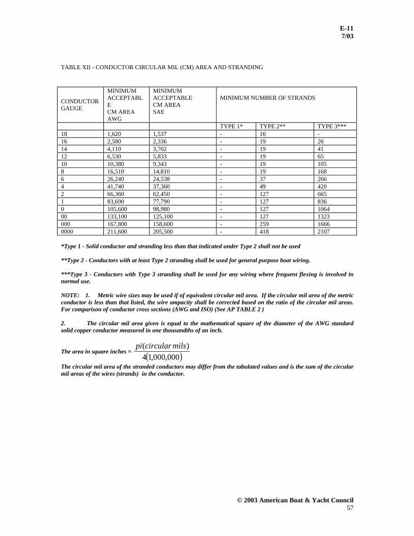
E-11 7/03
© 2003 American Boat & Yacht Council 57
TABLE XII - CONDUCTOR CIRCULAR MIL (CM) AREA AND STRANDING
CONDUCTOR GAUGE
MINIMUM ACCEPTABLE CM AREA AWG
MINIMUM ACCEPTABLE CM AREA SAE
MINIMUM NUMBER OF STRANDS
TYPE 1* TYPE 2** TYPE 3*** 18 1,620 1,537 - 16 - 16 2,580 2,336 - 19 26 14 4,110 3,702 - 19 41 12 6,530 5,833 - 19 65 10 10,380 9,343 - 19 105 8 16,510 14,810 - 19 168 6 26,240 24,538 - 37 266 4 41,740 37,360 - 49 420 2 66,360 62,450 - 127 665 1 83,690 77,790 - 127 836 0 105,600 98,980 - 127 1064 00 133,100 125,100 - 127 1323 000 167,800 158,600 - 259 1666 0000 211,600 205,500 - 418 2107 *Type 1 - Solid conductor and stranding less than that indicated under Type 2 shall not be used **Type 2 - Conductors with at least Type 2 stranding shall be used for general purpose boat wiring. ***Type 3 - Conductors with Type 3 stranding shall be used for any wiring where frequent flexing is involved in normal use. NOTE: 1. Metric wire sizes may be used if of equivalent circular mil area. If the circular mil area of the metric conductor is less than that listed, the wire ampacity shall be corrected based on the ratio of the circular mil areas. For comparison of conductor cross sections (AWG and ISO) (See AP TABLE 2 ) 2. The circular mil area given is equal to the mathematical square of the diameter of the AWG standard solid copper conductor measured in one thousandths of an inch.
The area in square inches = ( )000,000,14)( milscircularpi
The circular mil area of the stranded conductors may differ from the tabulated values and is the sum of the circular mil areas of the wires (strands) in the conductor.

E-11 7/03
© 2003 American Boat & Yacht Council 58
TABLE XIII – CONDUCTOR AMPACITY – FLEXIBLE CORDS [60°C (140°F) INSULATED RATING] AMPACITY OF INSULATED COPPER CONDUCTORS
(SEE NOTES (1) AND (2)) OUTSIDE ENGINE SPACES INSIDE ENGINE SPACES 30°C (86°F) AMBIENT 50°C (122°F) AMBIENT CONDUCTOR NOMINAL CM 3 CURRENT 2 CURRENT 3 CURRENT 2 CURRENT SIZE AREA CARRYING CARRYING CARRYING CARRYING (AWG) (SEE NOTE (1)) CONDUCTORS CONDUCTORS CONDUCTORS CONDUCTORS
16 2,580 10 13 6 8 14 4,110 15 18 9 11 12 6,530 20 25 12 15 10 10,380 25 30 15 20 8 16,510 35 40 20 25 6 26,240 45 55 30 35 4 41,740 60 70 35 40 2 66,360 80 95 50 55
NOTES: 1. Current ratings are for not more than two or three current carrying conductors in a flexible cord as indicated. Reduce the current rating to 80 percent of values shown for four to six current carrying conductors. 2. The ampacity of shore cables shall be based on 86oF (30oC) ambient.
TABLE XIV - WIRING COLOR CODE
Color Use Green, or green w/yellow stripe(s)
DC grounding conductors
Black, or yellow DC negative conductors Red DC positive conductors

E-11 7/03
© 2003 American Boat & Yacht Council 59
TABLE XV – ENGINE AND ACCESSORY WIRING COLOR CODE
COLOR ITEM USE Yellow w/Red Stripe (YR) Starting Circuit Starting switch to solenoid Brown/Yellow Stripe (BY) or Yellow (Y) - see note
Bilge Blowers Fuse or switch to blowers
Dark Gray (Gy) Navigation Lights
Tachometer Fuse or switch to lights Tachometer sender to gauge
Brown (Br) Generator Armature Generator armature to regulator Alternator Charge Light
Pumps
Generator Terminal/alternator Auxiliary terminal to light to regulator Fuse or switch to pumps
Orange (O) Accessory Feed Ammeter to alternator or generator output and
accessory fuses or switches. Distribution panel to accessory switch Purple (Pu) Ignition Ignition switch to coil and electrical instruments. Instrument Feed Distribution panel to electric instruments Dark Blue Cabin and Instrument Lights Fuse or switch to lights Light Blue (Lt Bl) Oil Pressure Oil pressure sender to gauge Tan Water Temperature Water temperature sender to gauge Pink (Pk) Fuel Gauge Fuel gauge sender to gauge Green/Stripe (G/x) (Except G/Y)
Tilt down and/or Trim in Tilt and/or trim circuits
Blue/Stripe (Bl/x) Tilt up and/or Trim out Tilt and/or trim circuits
NOTE: If yellow is used for DC negative, blower must be brown with yellow stripe.
TABLE XVI – TENSILE TEST VALUES FOR CONNECTIONS
CONDUCTOR SIZE TENSILE FORCE CONDUCTOR SIZE TENSILE FORCE GAUGE POUNDS NEWTONS GAUGE POUNDS NEWTONS 18 10 44 4 70 311 16 15 66 3 80 355 14 30 133 2 90 400 12 35 155 1 100 444 10 40 177 0 125 556 8 45 200 00 150 667 6 50 222 000 175 778 5 60 266 0000 225 1000

E-11 7/03
© 2003 American Boat & Yacht Council 60
AP TABLE 1 – CONDUCTORS
AWG
INSULATION
TYPE
NOMINAL WALL
THICKNESS (MILS)
MAXIMUM OPERATING
TEMP. DRY (°C)
MAXIMUM OPERATING
TEMP. WET (°C)
BREAK DOWN VOLTAGE
(V)
OIL RESISTANT
TEMP. (°C)
COMMENTS
14-10 THW 45 75 75 600 Thermoplastic 8-2 THW 60
1-4/0 THW 80 14-10 TW 30 75 60 600 Thermoplastic
8 TW 45 14-12 THWN 19 105 75 600 60 PVC/Nylon
10 THWN 20 14-12 XHHW 30 90 75 600 X-linked
10 8-2 45
1-4/0 55 18-10 MTW 45 90 60 600 Heavy Wall
PVC 8 MTW 45 6 MTW 60
18-8 TW 30 90 60 600 Light Wall PVC
18-10 AWM Style #1230 PVC
30 105 60 600 60
18-8 AWM Style #1231 PVC
45 105 60 600 60
8-2 AWM Style #1232 PVC
60 105 60 600 60
1-4/0 AWM Style #1232 PVC
80 105 60 600 60
18-10 AWM Style #1275 PVC
60 105 60 600 60
18-10 AWM Style #1345 PVC
30 105 75 600 60
8-2 AWM Style #1346 PVC
60 105 75 600 60
18-10 UL 1426 Boat Cable
30 105 75 600 60
8 Boat Cable 45 105 75 600 60 6-2 Boat Cable 60 105 75 600 60
1-4/0 Boat Cable 80 105 75 600 60 NOTES: 1. AWM must be accompanied by a style number. 2. AWM style 1015 is not tested for moisture. 3. Some of the listed types are not commonly available in standard construction for sizes smaller than 8 AWG. However, these types are acceptable if obtainable.

E-11 7/03
© 2003 American Boat & Yacht Council 61
AP TABLE 2 – COMPARISON OF CONDUCTOR CROSS –SECTION
AWG (Ga.)
AWG
ISO
mm²
Ampacity (105°C Insulation)
mm²
Ampacity (105°C Insulation)
18 0.82 20 0.75 16 1.0 20
16 1.31 25 1.5 25 14 2.08 35 2.5 35 12 3.31 45 4.0 45 10 5.26 60 6.0 60 8 8.39 80 10.0 90 6 13.3 120 16.0 130 4 21.2 160 3 26.6 180 25.0 170 2 33.6 210 35.0 210 1 42.4 245 0 53.5 285 50.0 270
2/0 67.7 330 70.0 330 3/0 85.2 385 95.0 390 4/0 107 445
250 kcm 127 500 120 450 300 kcm 152 550 150 475
NOTES: 1. Ampacity for ISO sizes is from ISO/FDIS 10133 “Electrical Systems-Extra-low-voltage D.C. Installations” dated February 2, 1999. 2. Ampacity of AWG is from E-11 TABLE VII – A and NEC for 221°F (105°C) insulation no more than two conductors bundled in air at 70oF (21oC).
* * * * * ABYC technical board rules provide that all reports, including standards and technical information reports, are advisory only. Their use is entirely voluntary. They are believed to represent, as of the date of publication, the consensus of knowledgeable persons, currently active in the field of small craft, on performance objectives that contribute to small boat safety. The American Boat & Yacht Council assumes no responsibility whatsoever for the use of, or failure to use, standards or technical information reports promulgated by it, their adaptation to any processes of a user, or any consequences flowing therefrom.. Prospective users of the standards and technical information reports are responsible for protecting themselves against liability for infringement of patents. The American Boat & Yacht Council standards are guides to achieving a specific level of design or performance, and are not intended to preclude attainment of desired results by other means.