Embed Size (px)
Citation preview
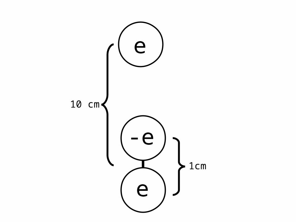
e
10 cm
1cm
e
-e
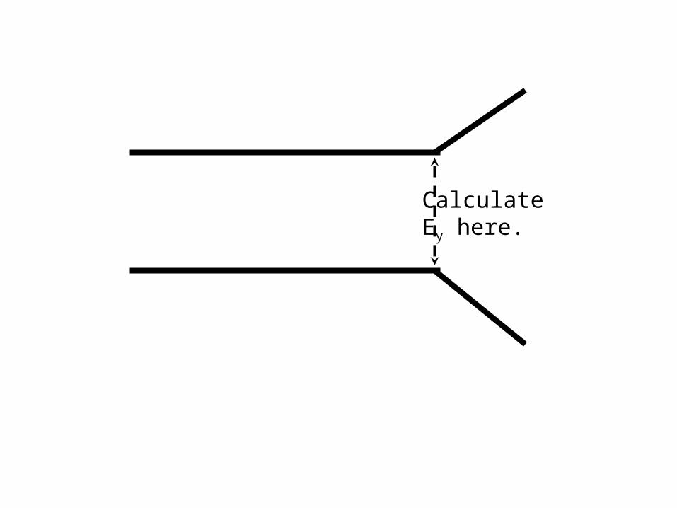
CalculateEy here.
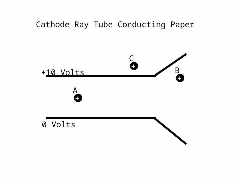
Cathode Ray Tube Conducting Paper
+10 Volts
0 Volts
A+
B+
C+
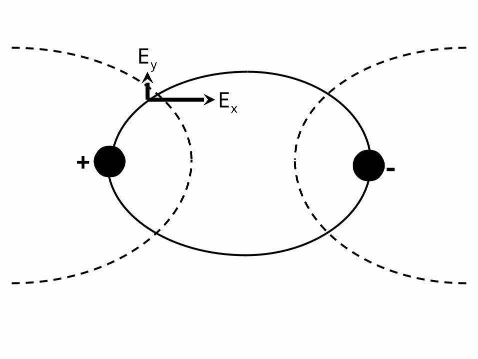
Ex
Ey
+ -
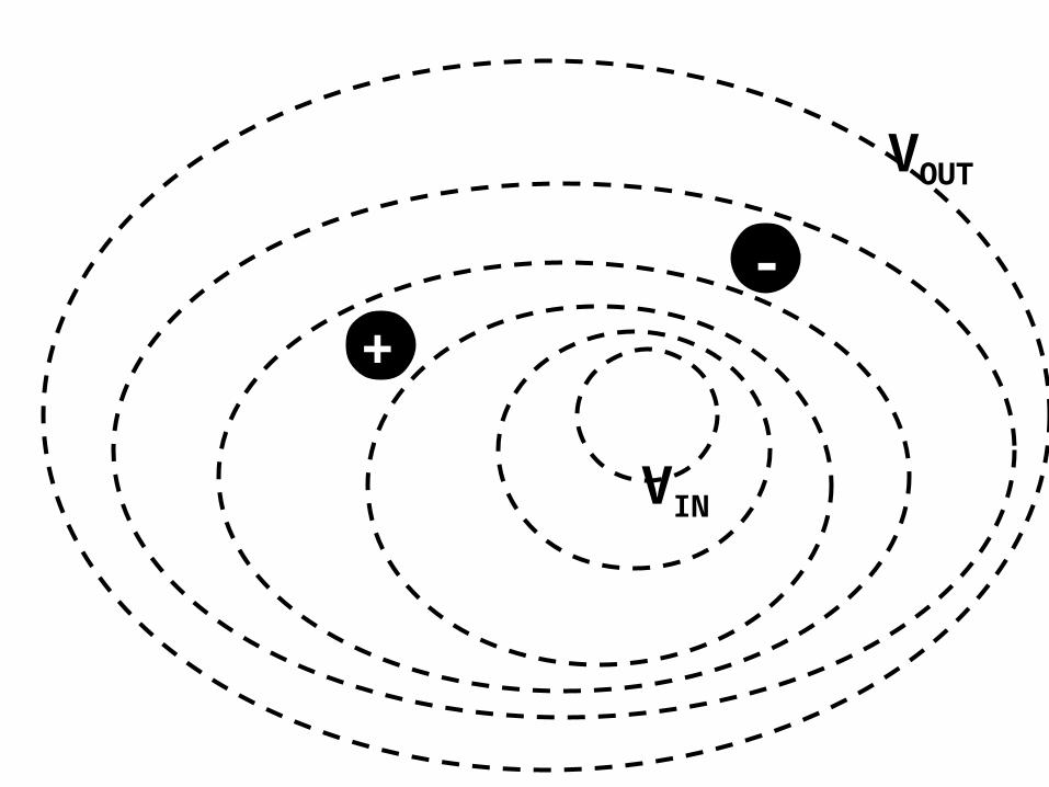
+
VOUT
VIN
-
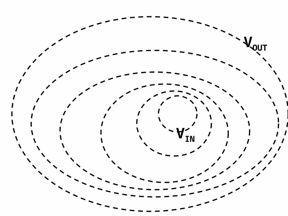
VOUT
VIN
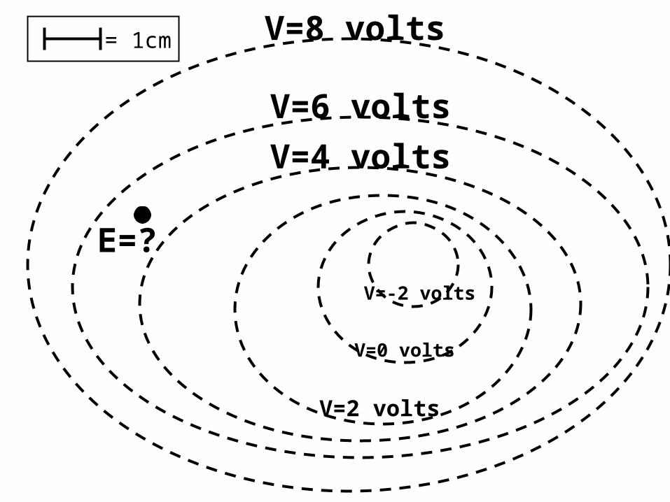
V=6 volts
V=8 volts
V=4 volts
V=2 volts
V=0 volts
V=-2 volts
= 1cm
E=?
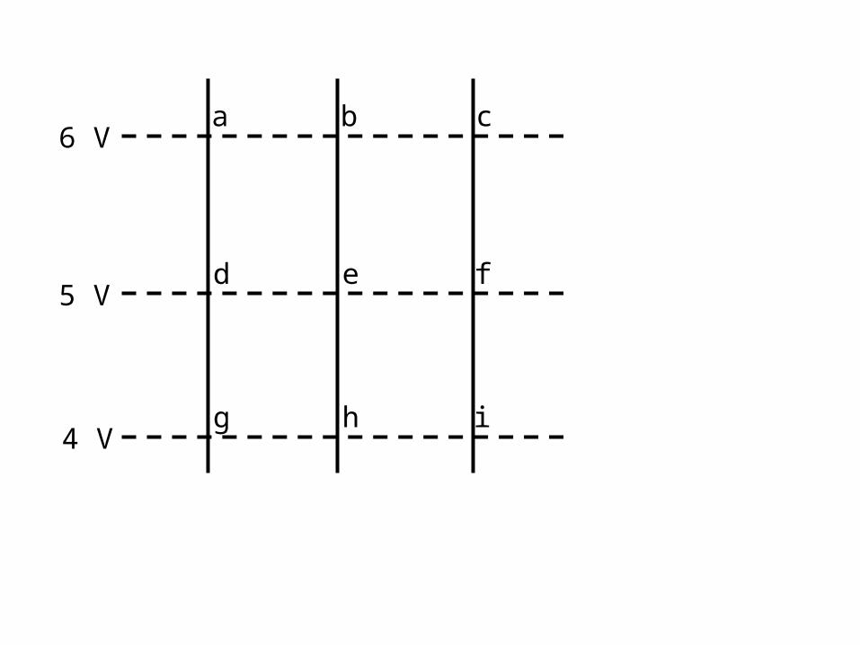
6 V
5 V
4 V
a b c
d e f
g h i
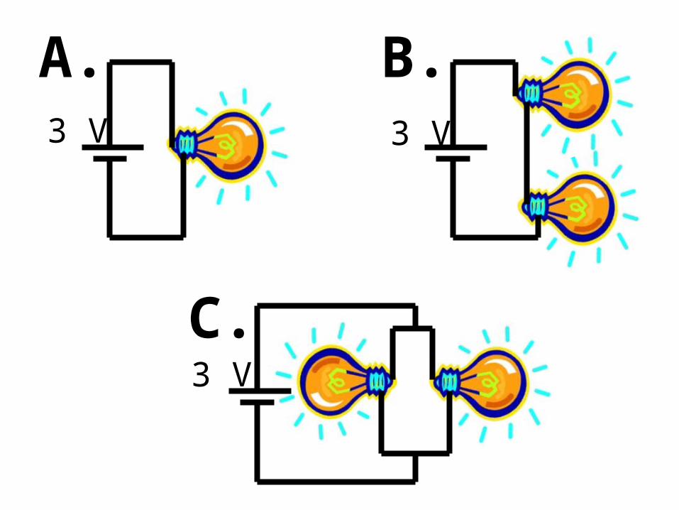
3 V 3 V
3 V
A. B.
C.
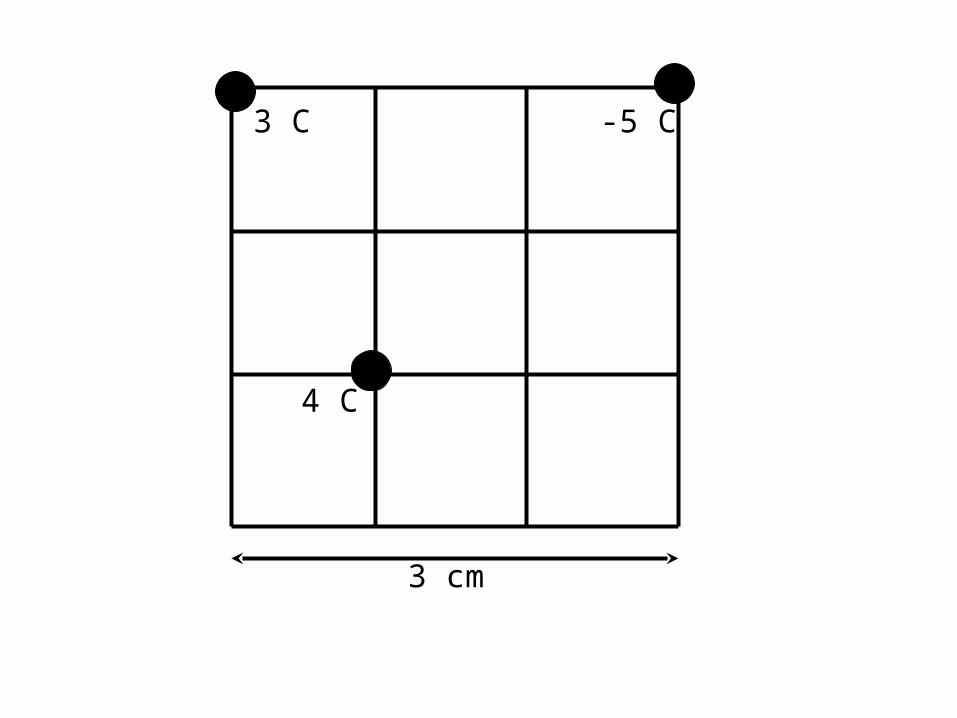
3 C
4 C
3 cm
-5 C
3 C
4 C
3 cm
-5 C
q

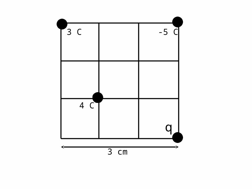
3 C
4 C
3 cm
-5 C
q
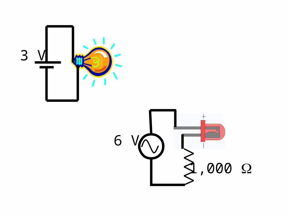
3 V
6 V
1,000
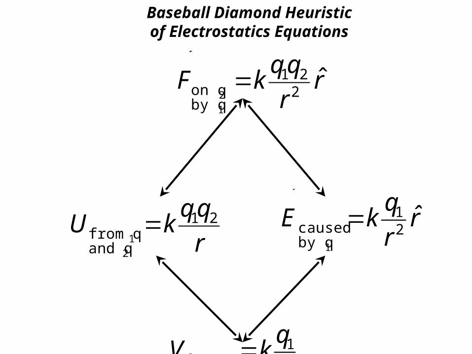
F on q 2
by q1
kq1q2
r2ˆ r
E caused
by q1
kq1
r2ˆ r
Ufrom q1and q 2
kq1q2
r
Vfrom q1k
q1
r
Baseball Diamond Heuristicof Electrostatics Equations
E caused
by q1
kq1
r2ˆ r
Ufrom q1and q 2
kq1q2
r
Vfrom q1point charge
kq1
r
F on q 2
by q1
q2
E from q1
Won q 2 q2V
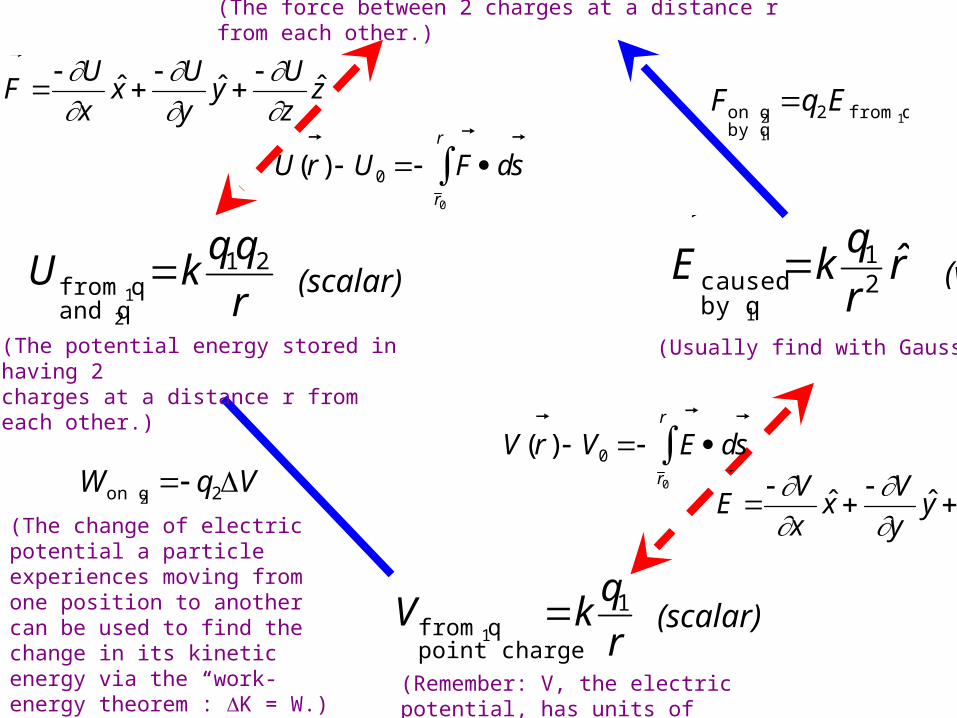
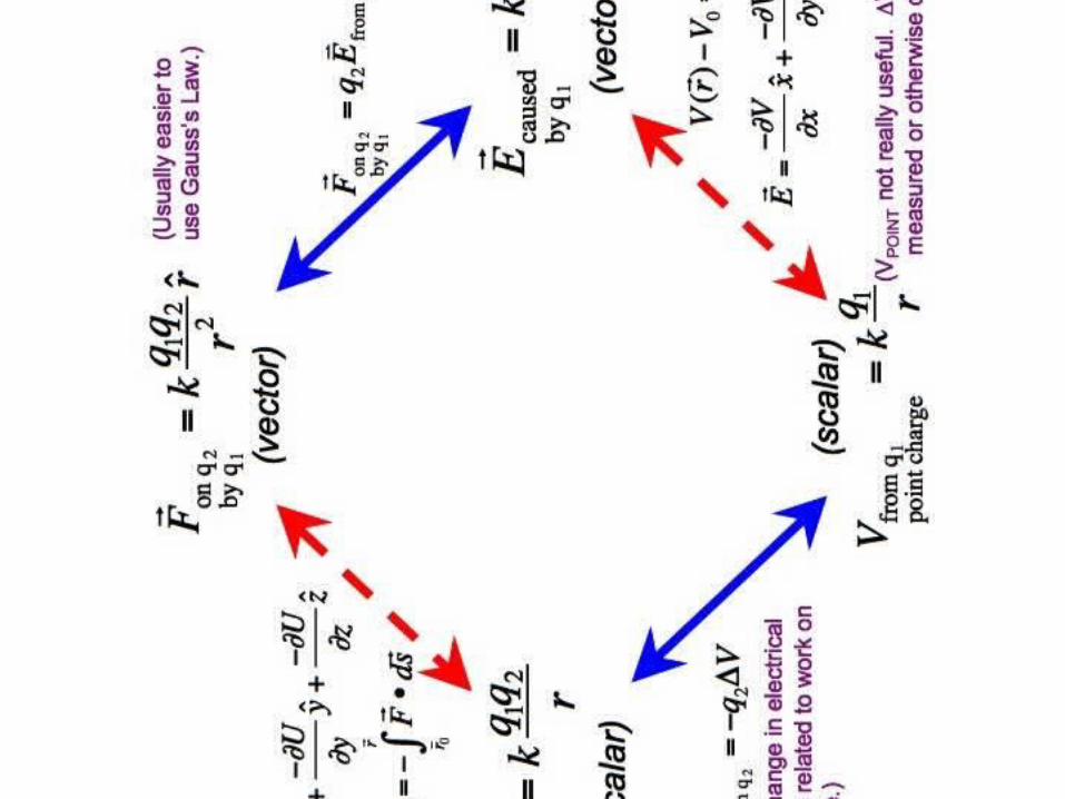
(Usually find with Gauss’s Law.)
(Remember: V, the electric potential, has units of energy per unit charge.)
F
U
xˆ x
U
yˆ y
U
zˆ z
U(r ) U0
F d
s
r 0
r
E
V
xˆ x
V
yˆ y
V
zˆ z
V (r ) V0
E d
s
r 0
r
(scalar)
(scalar)
(vector)
(The change of electric potential a particle experiences moving from one position to another can be used to find the change in its kinetic energy via the “work-energy theorem”: K = W.)
(The potential energy stored in having 2charges at a distance r from each other.)
(The force between 2 charges at a distance r from each other.)
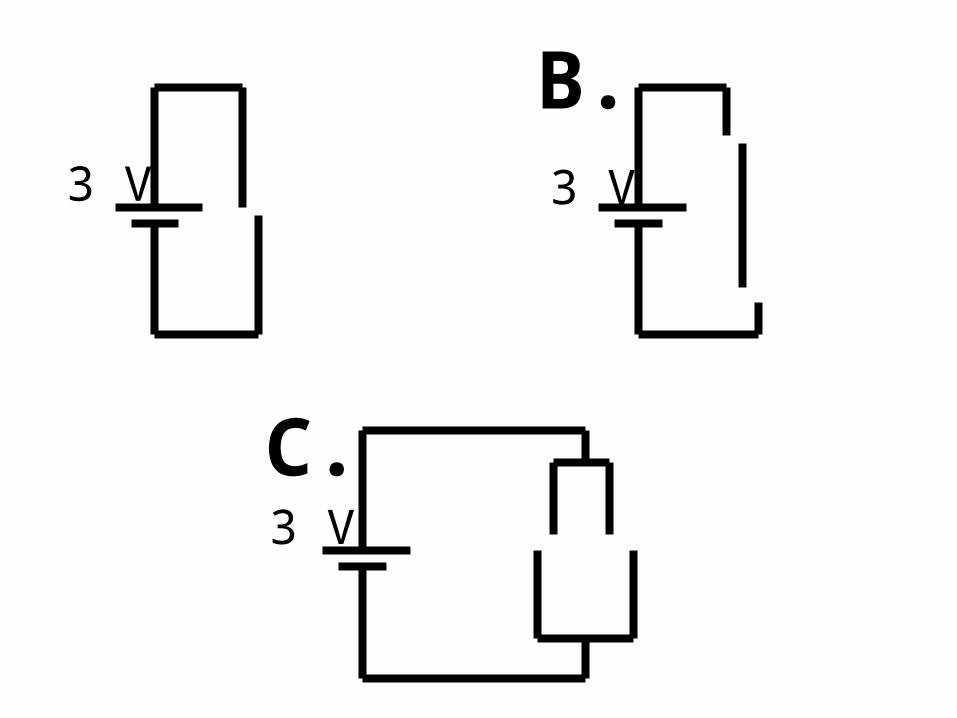
3 V 3 V
3 V
B.
C.
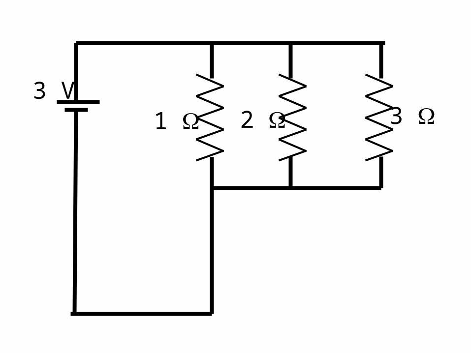
3 V1 2 3
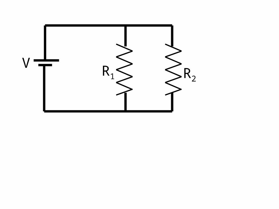
VR1 R2
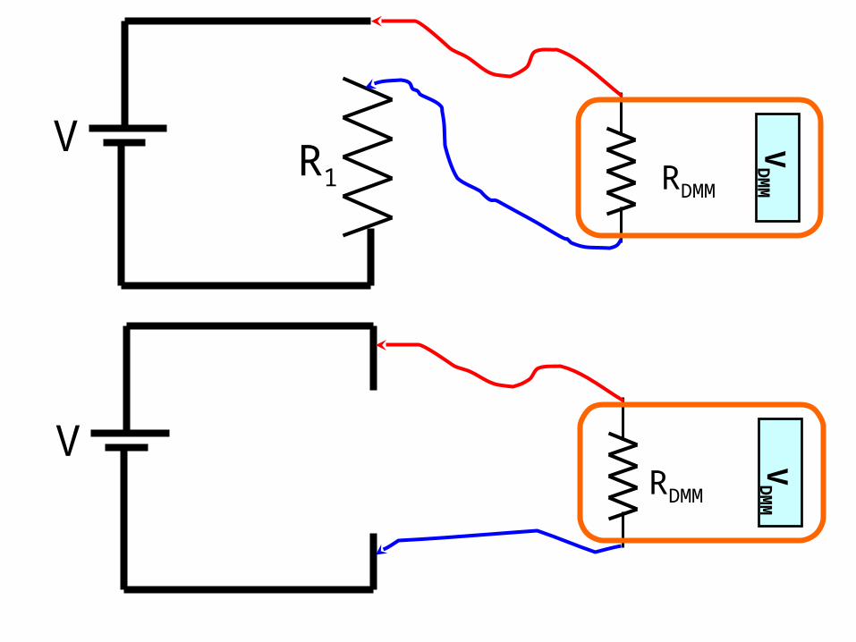
VRDMM
VD
MM
VR1 RDMM
VD
MM
3 V1 2 3
1
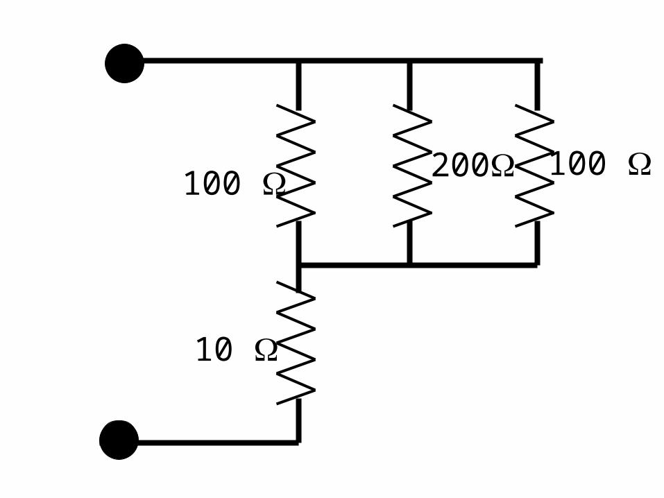
100 200 100
10
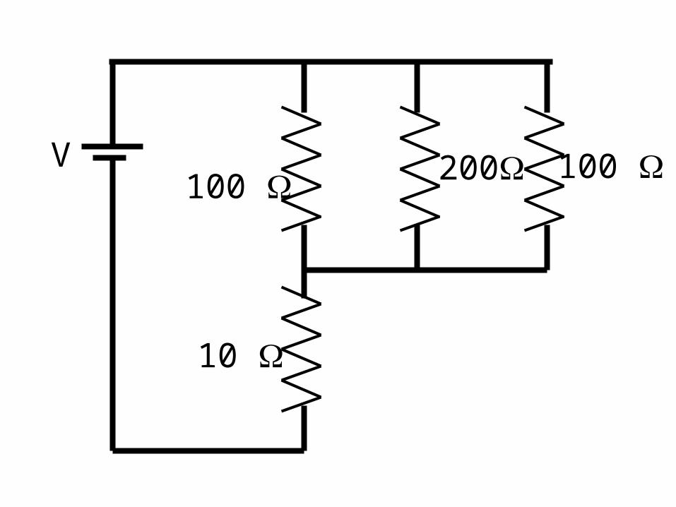
100 200 100
10
V
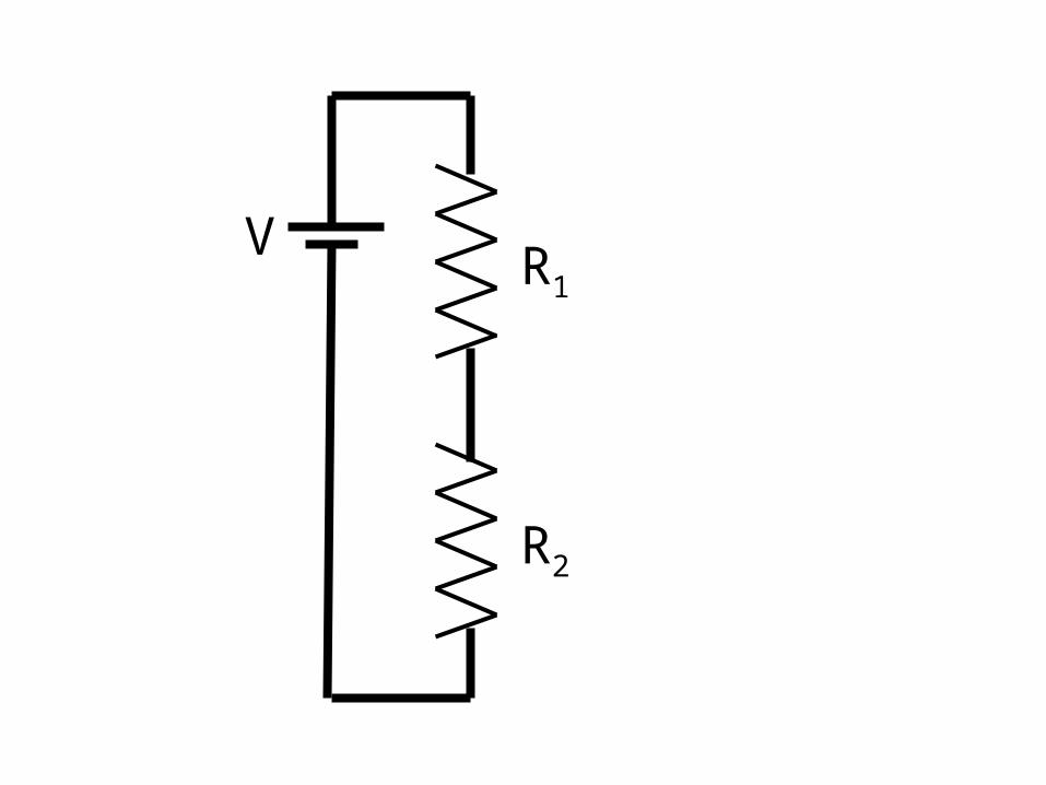
VR1
R2
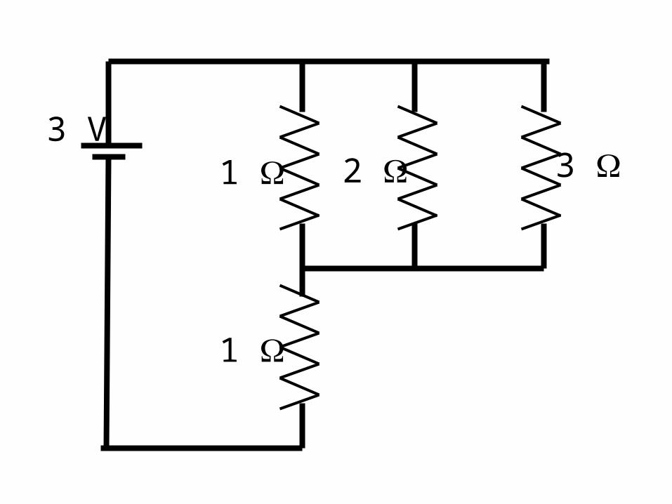
3 V1 2 3
1 2
3 V1 2 3
1 2
1
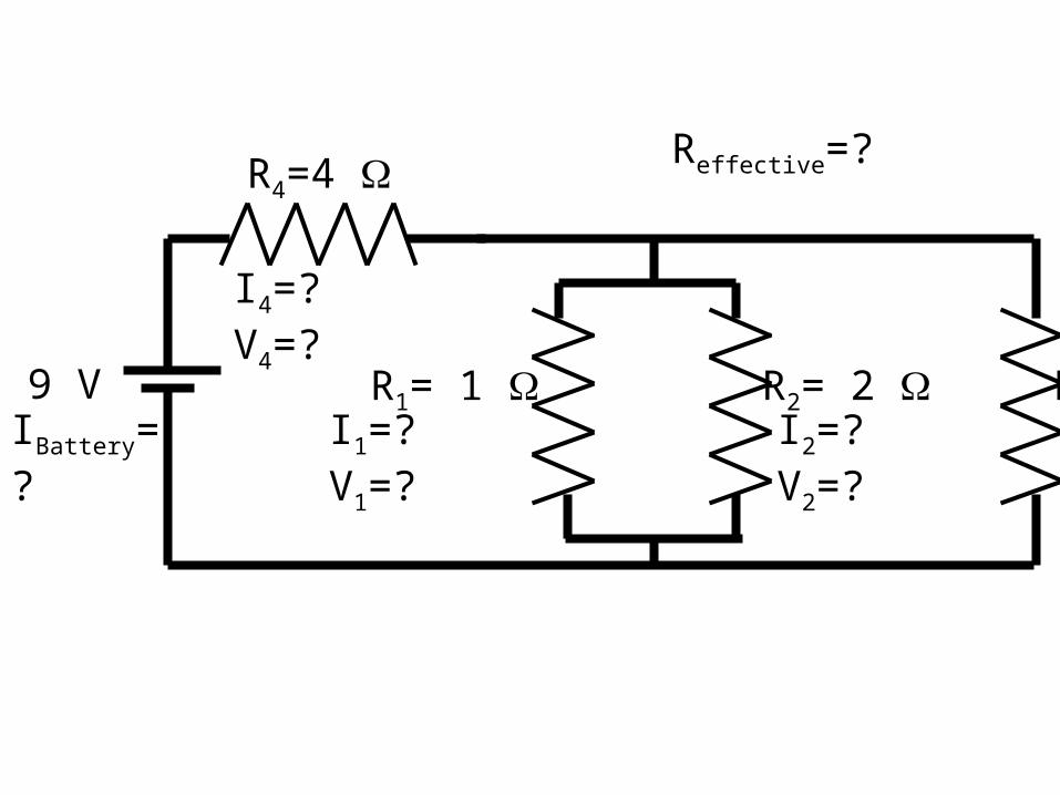
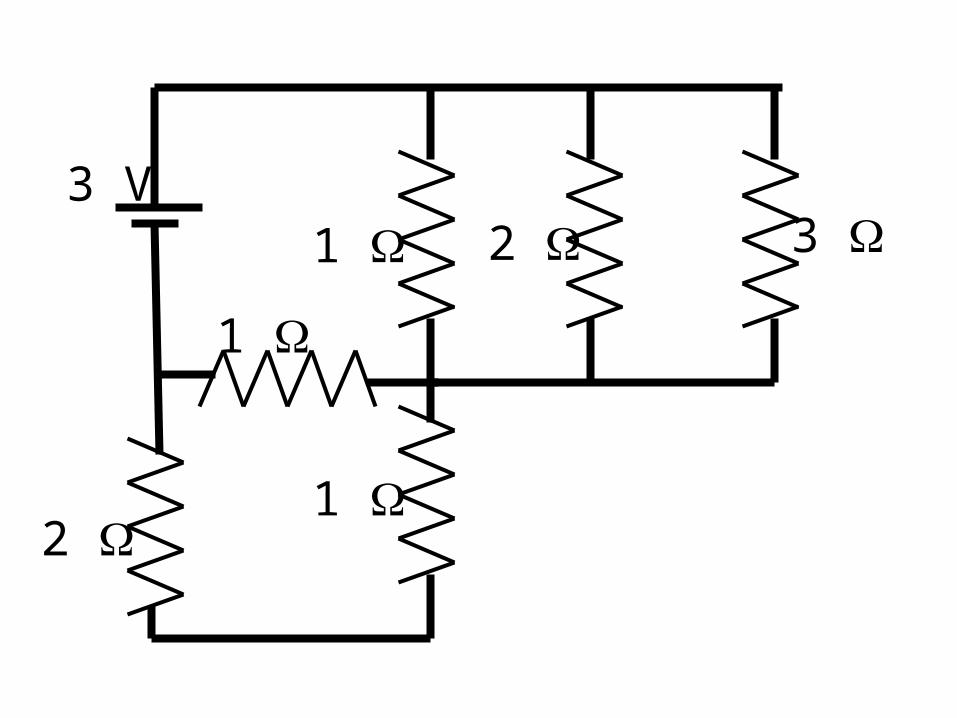
9 V R1= 1 R2= 2 R3= 3
R4=4
I4=? V4=?
I1=? V1=? I2=? V2=? I3=? V3=?IBattery=?
Reffective=?
SCOPE
t V
t
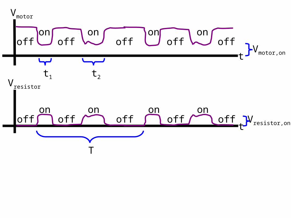
Vmotor
t
Vresistor
T
t1 t2
Vmotor,on
Vresistor,on
on on on onoff off off offoff
on on on onoff off off offoff
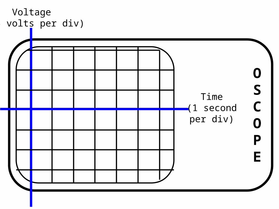
OSCOPE
Voltage(0.5 volts per div)
Time(1 secondper div)
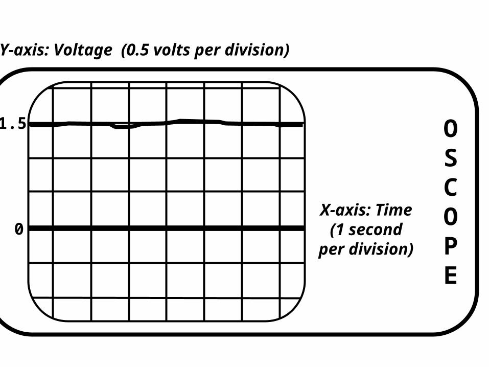
OSCOPE
Y-axis: Voltage (0.5 volts per division)
X-axis: Time(1 second
per division)0
1.5
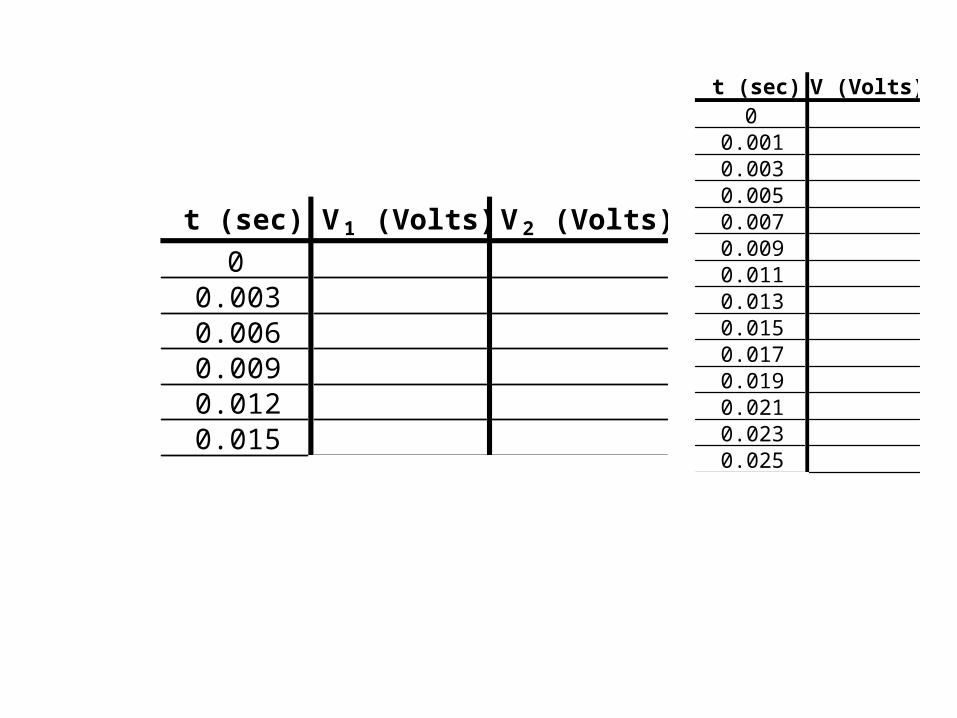
t (sec) V (Volts)0
0.0010.0030.0050.0070.0090.0110.0130.0150.0170.0190.0210.0230.025
t (sec) V1 (Volts) V2 (Volts)
00.0030.0060.0090.0120.015
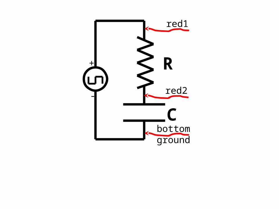
R
C
+
-
red1
bottomground
red2
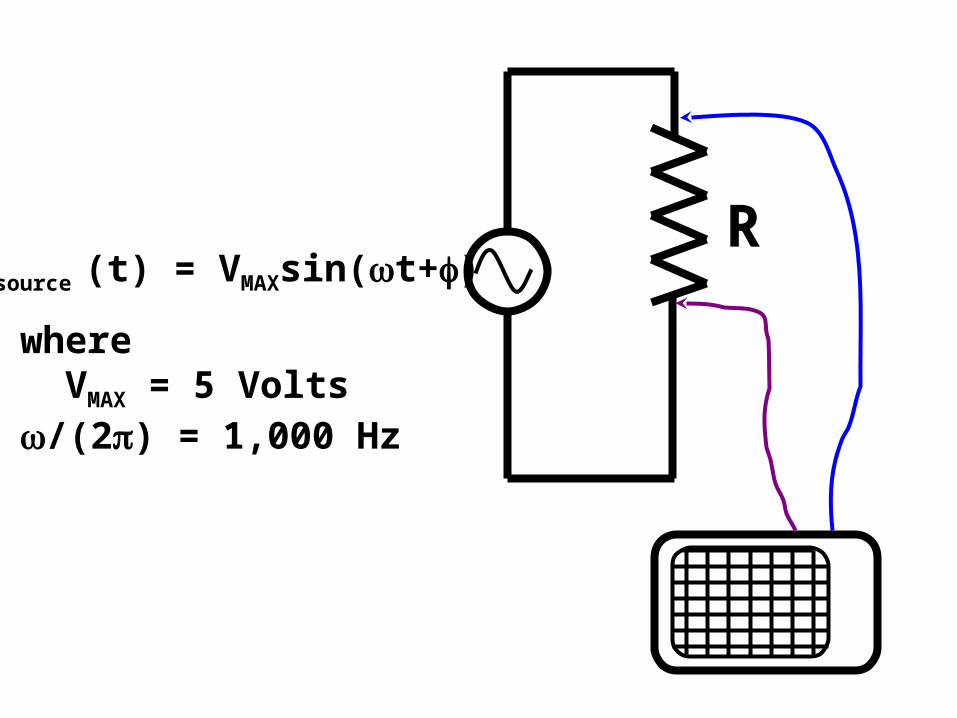
RVsource (t) = VMAXsin(t+)
where VMAX = 5 Volts/(2) = 1,000 Hz
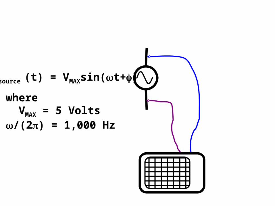
Vsource (t) = VMAXsin(t+)
where VMAX = 5 Volts/(2) = 1,000 Hz
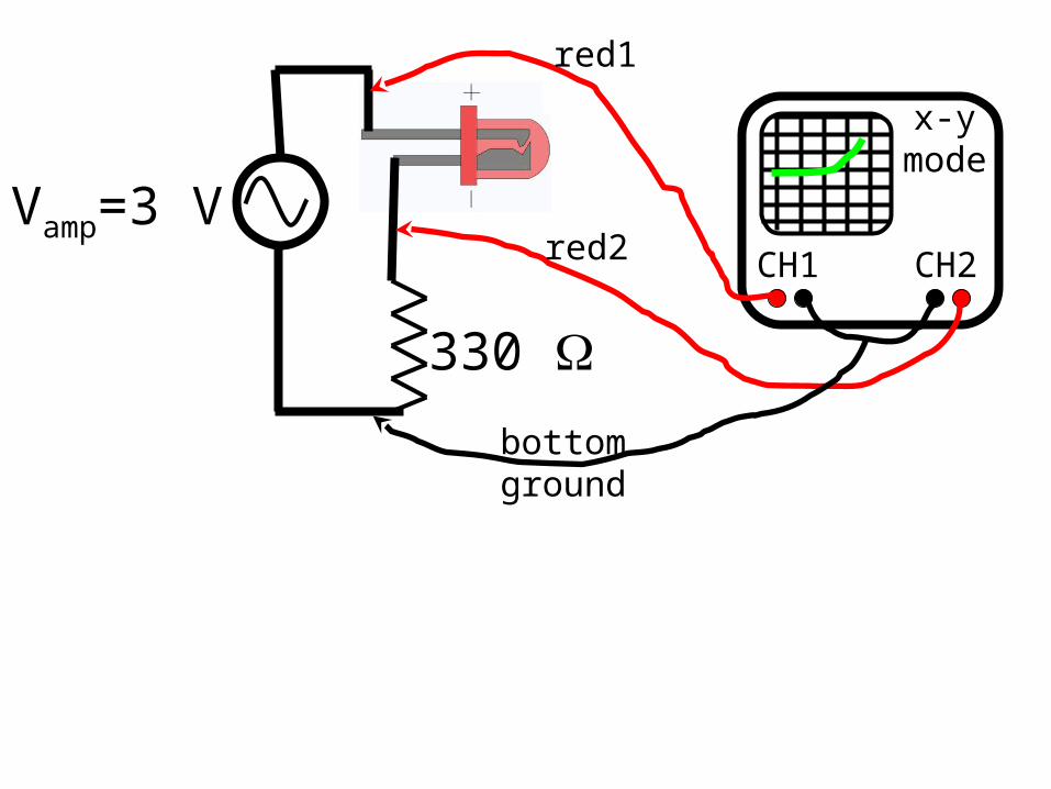
Vamp=3 V
330
CH1 CH2
red1
red2
bottomground
x-ymode
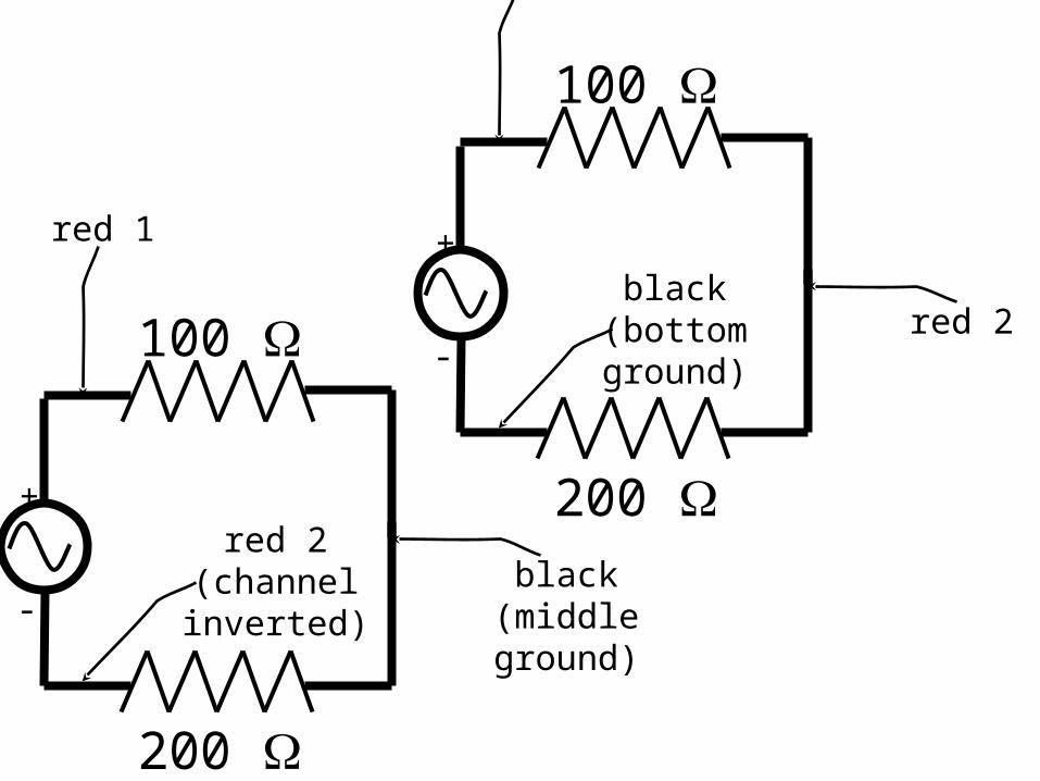
200
100
red 1
red 2(channelinverted)
black(middleground)
+
-
200
100
red 1
black(bottomground)
red 2
+
-
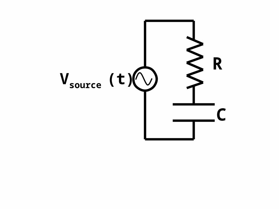
R
C
Vsource (t)
SCOPE
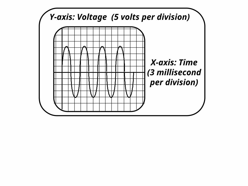
Y-axis: Voltage (5 volts per division)
X-axis: Time(3 millisecondper division)
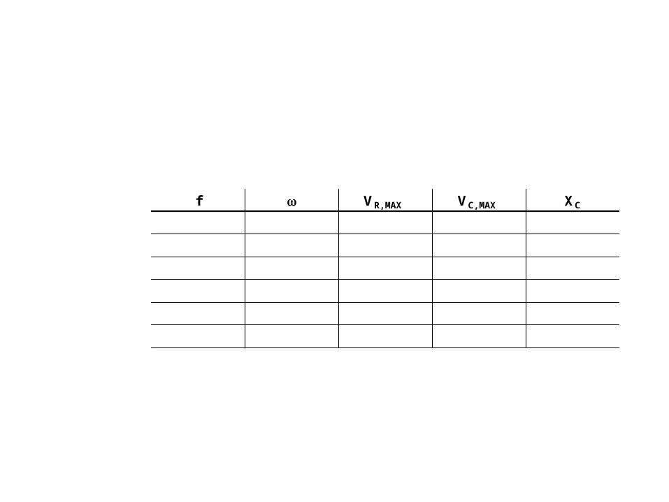
f VR,MAX VC,MAX XC
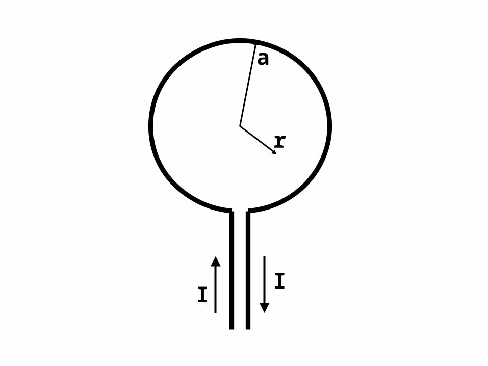
I
I
I
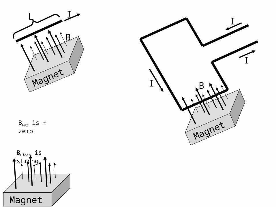
Magnet
B
Magnet
BClose is strong
BFar is ~ zero
Magnet
B
IL
I
I
I
I
I
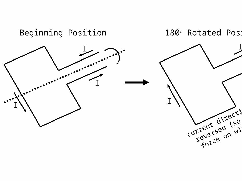
Beginning Position 180o Rotated Position
current direction
reversed (so is
force on wire)
I
I
I
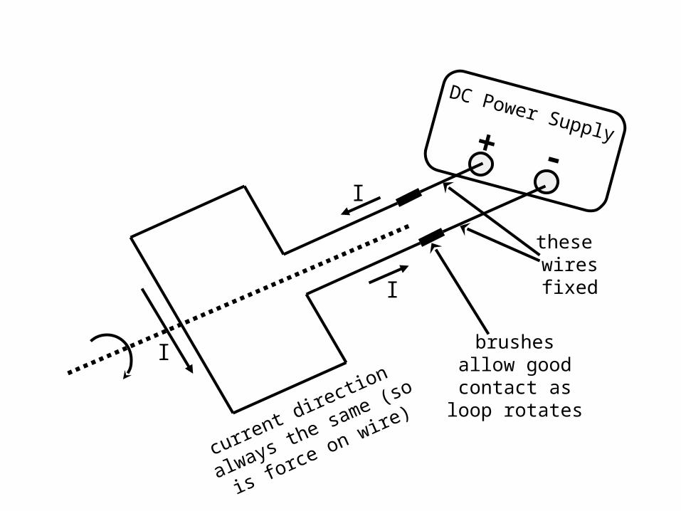
current direction
always the same (so
is force on wire)
DC Power Supply+ -
these wiresfixed
brushesallow goodcontact as
loop rotates
I
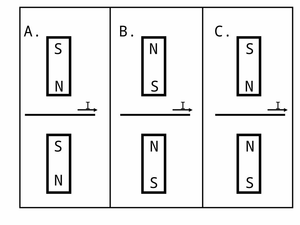
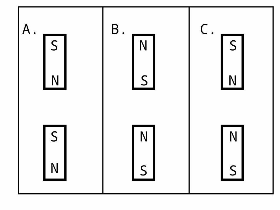
A.
NI
B.
SI
C.
N
S
S
N S
N
N
S S
N
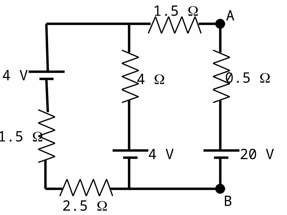
4 V 0.5
A
B
1.5
1.5
2.5
4
4 V 20 V

12 V
1 2 3
1
2
1
2
BA
TT
ER
YA
B
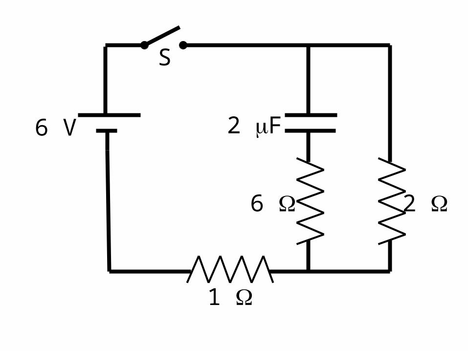
6
1
2
S
2 F6 V
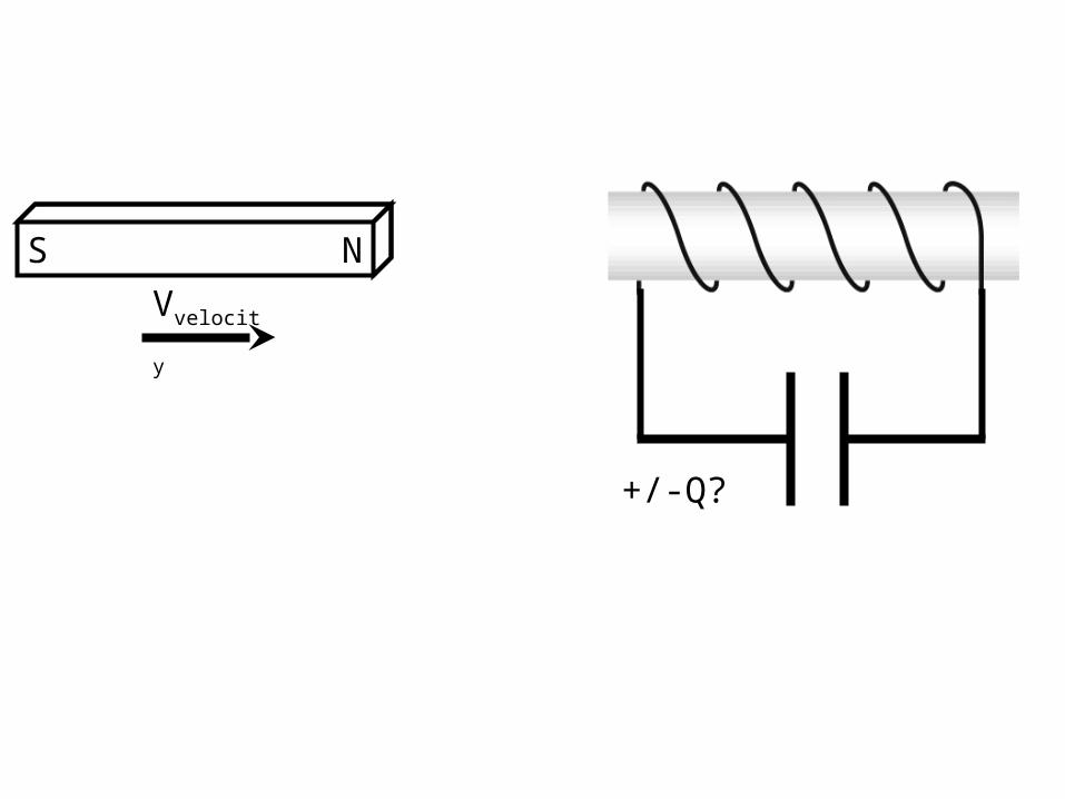
+/-Q?
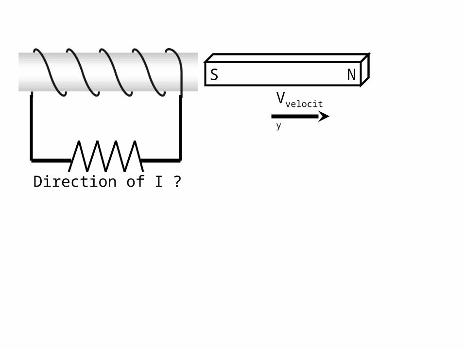
NS
Vvelocity
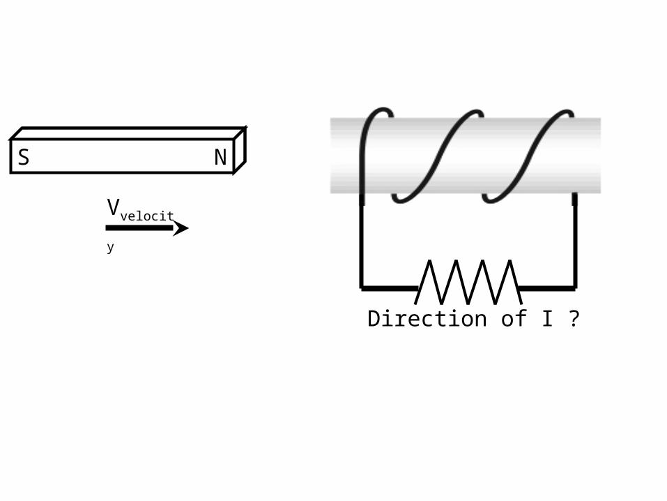
NS
Vvelocity
Direction of I ?
Direction of I ?
NS
Vvelocity
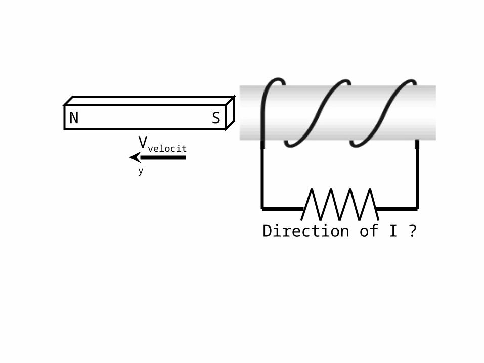
SN
Vvelocity
Direction of I ?
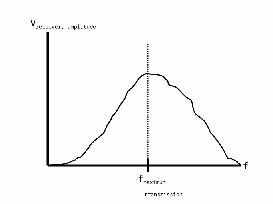
Vreceiver, amplitude
ffmaximum
transmission
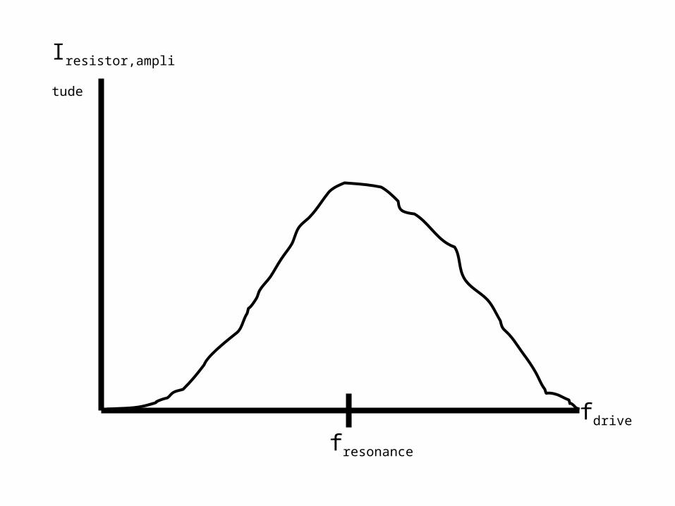
Iresistor,amplitude
fdrive
fresonance
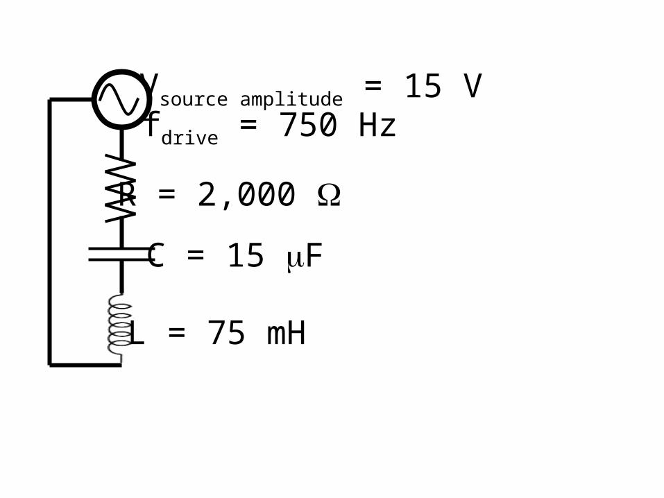
R = 2,000
C = 15 F
Vsource amplitude = 15 V
L = 75 mH
fdrive = 750 Hz
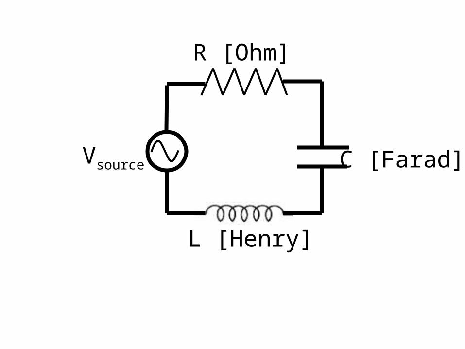
R [Ohm]
C [Farad]Vsource
L [Henry]
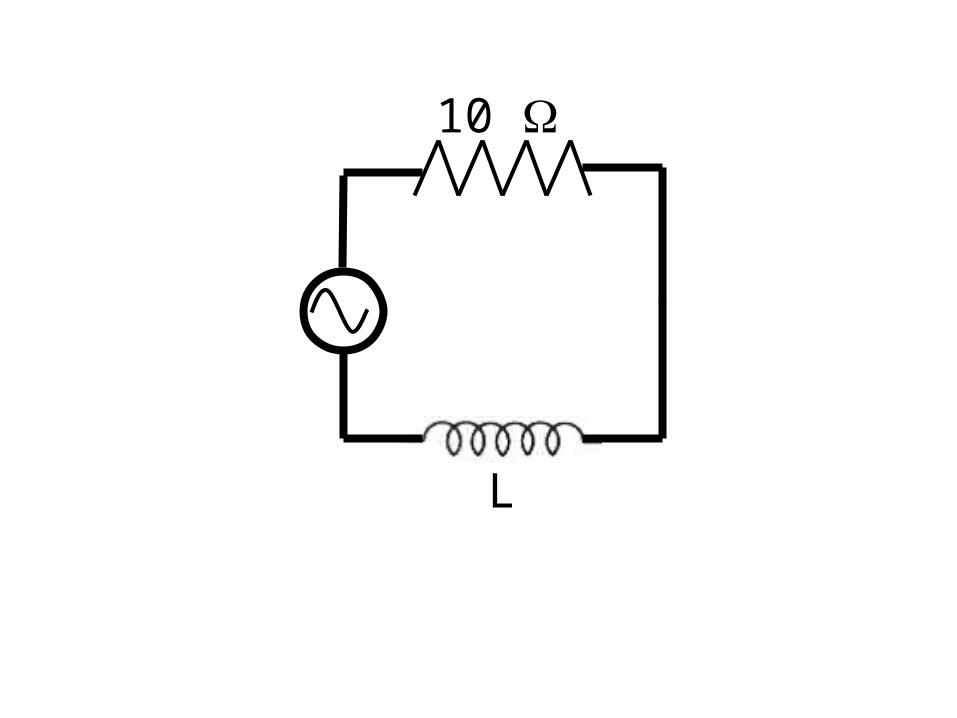
10
L
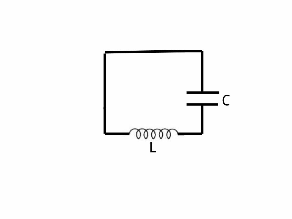
C
L
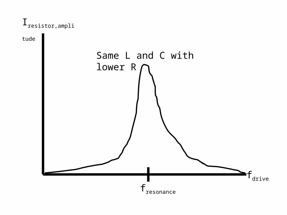
Iresistor,amplitude
fdrive
fresonance
Same L and C with lower R
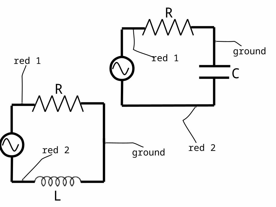
L
R
red 1
red 2 ground
C
R
red 1ground
red 2
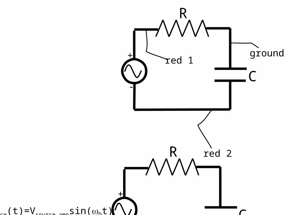
C
R
red 1ground
red 2
+
-
C
R
Vsource(t)=Vsource ampsin(Dt)
+
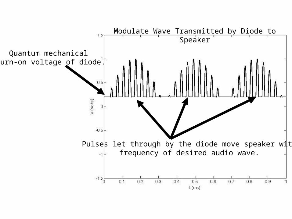
Pulses let through by the diode move speaker withfrequency of desired audio wave.
Quantum mechanical turn-on voltage of diode.
Modulate Wave Transmitted by Diode to Speaker
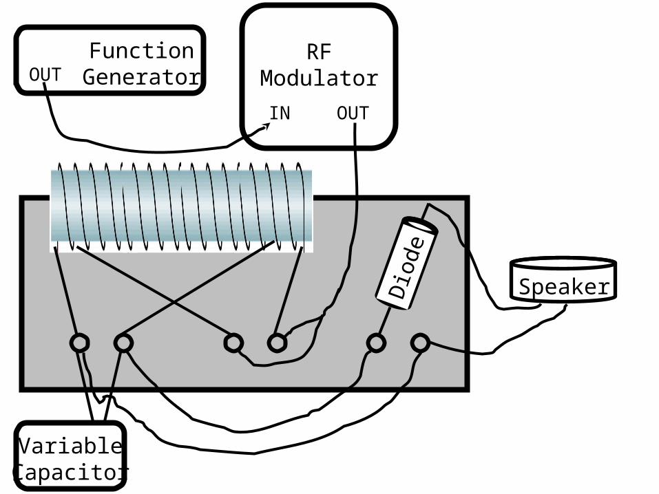
FunctionGenerator
RFModulator
IN OUT
OUT
VariableCapacitor
SpeakerDio
de
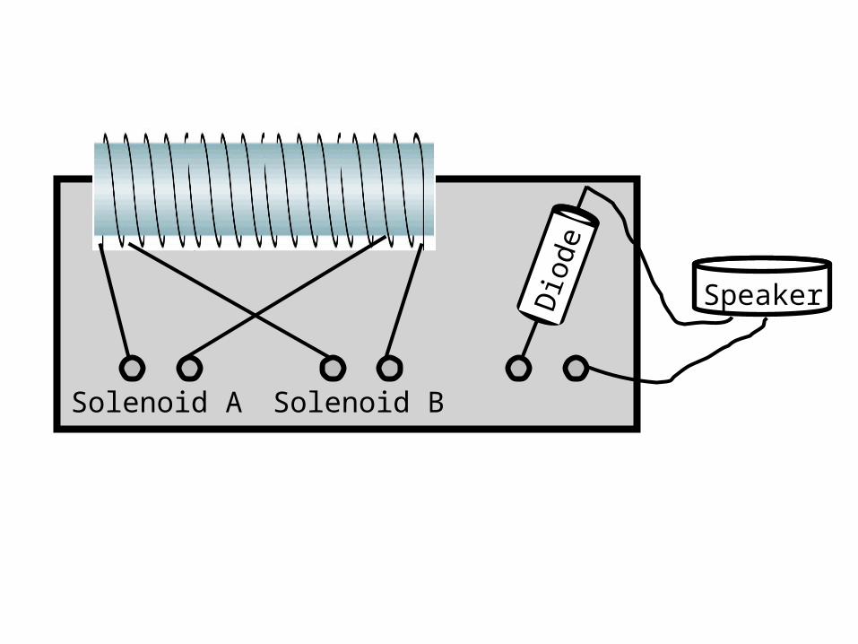
SpeakerDio
de
Solenoid A Solenoid B
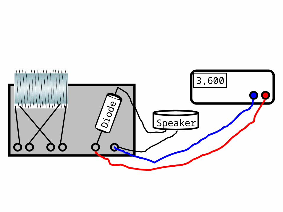
SpeakerDio
de
3,600
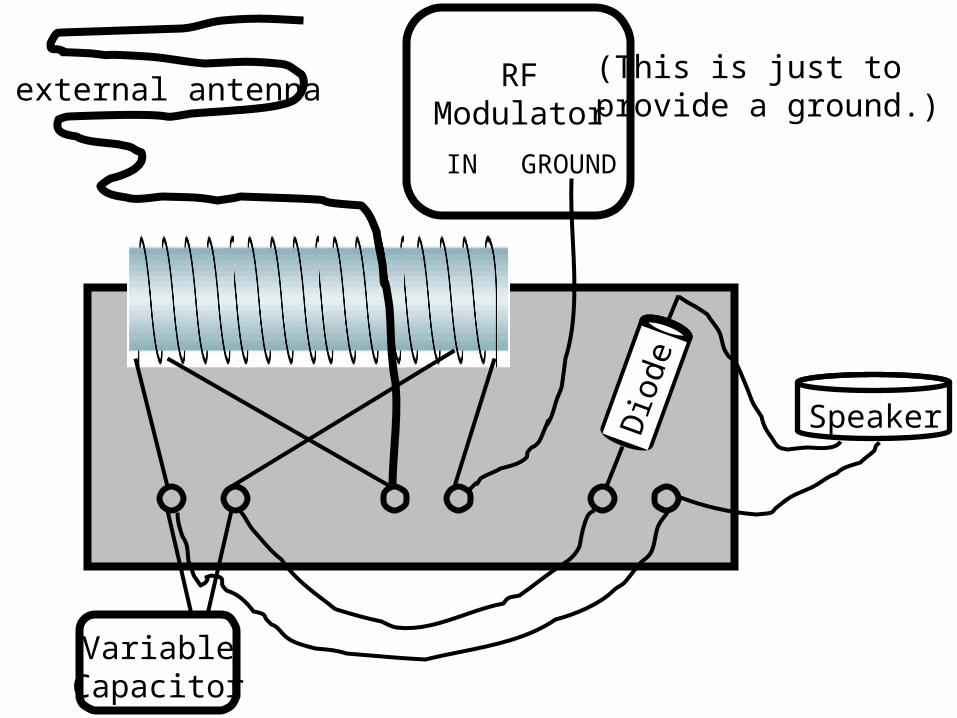
RFModulator
IN GROUND
VariableCapacitor
SpeakerDio
de
(This is just to provide a ground.)external antenna
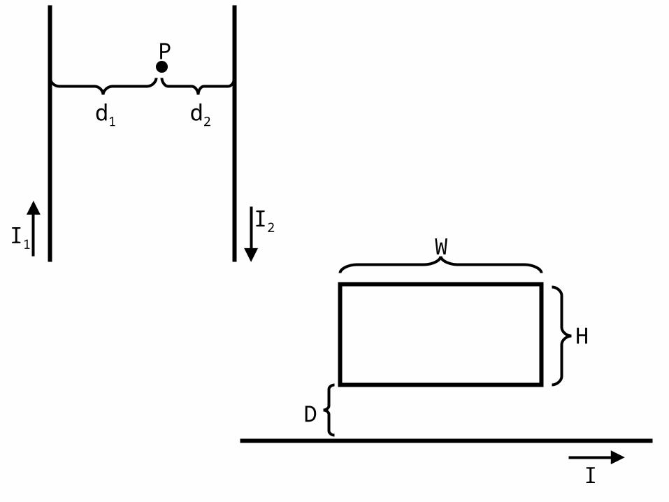
I2I1
P
d1 d2
I
W
H
D
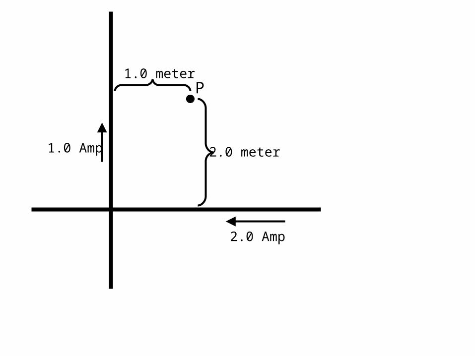
2.0 Amp
1.0 Amp
P1.0 meter
2.0 meter
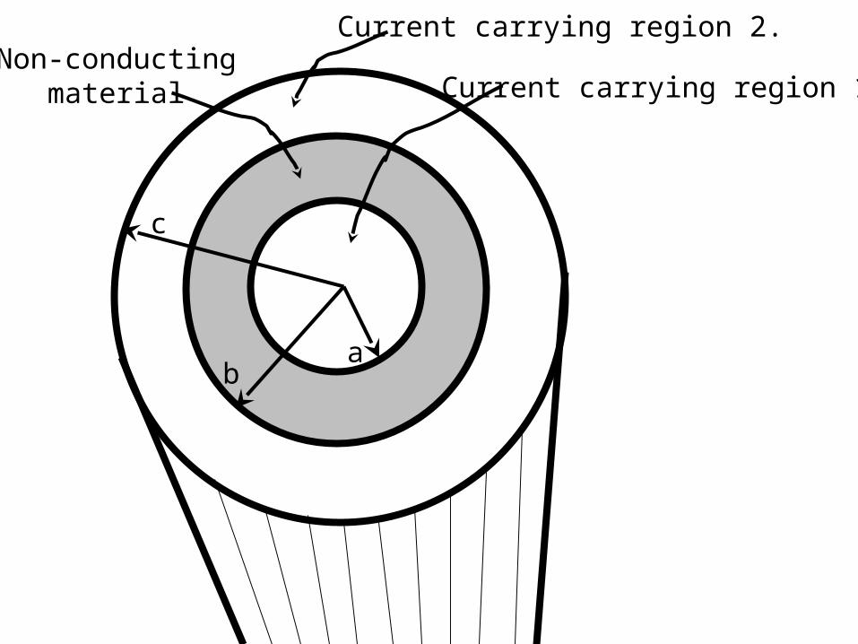
Current carrying region 2.
Current carrying region 1.Non-conducting
material
ab
c
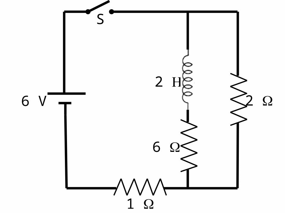
6
1
2
S
2 6 V
II
r
a
A.
N
B.
S
C.
N
S
S
N S
N
N
S S
N
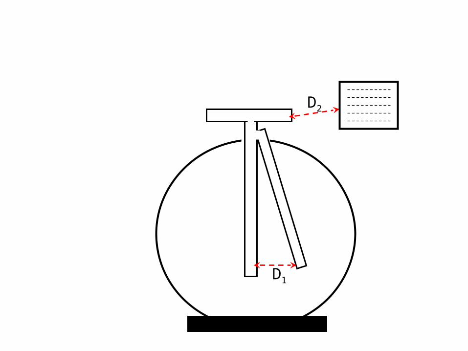
D1
D2
(use more frames if necessary)
Cartoon Frames
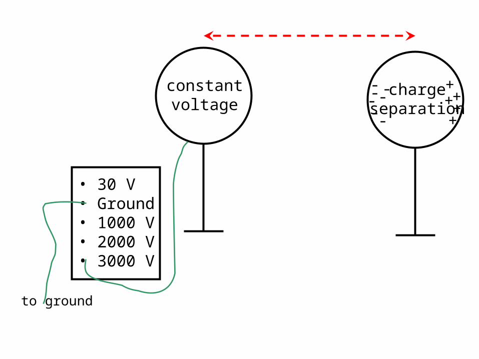
• 30 V• Ground• 1000 V• 2000 V• 3000 V
to ground
constantvoltage
chargeseparation
+++++- ---
- -
-
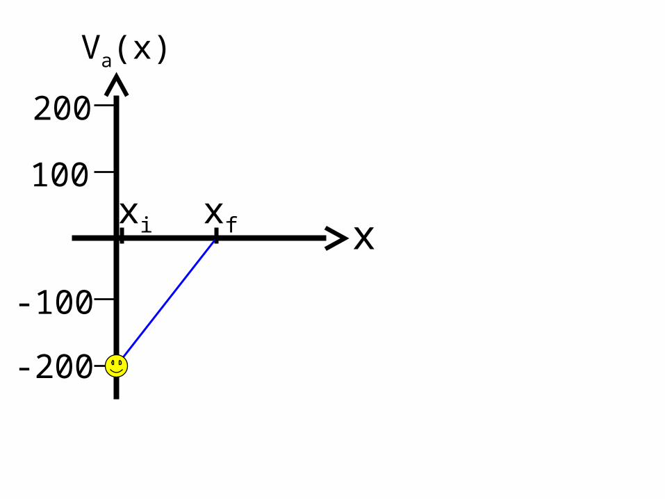
x
Va(x)
-200
100
-100
200
xi xf
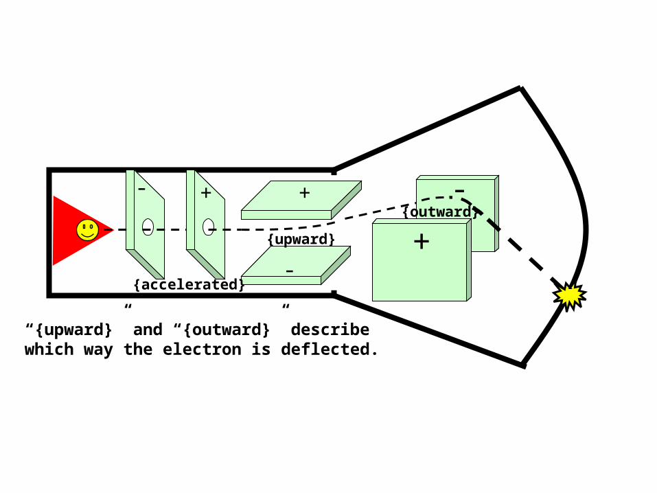
+
-
-
+{upward}
{outward}
“{upward}” and “{outward}” describewhich way the electron is deflected.
- +
{accelerated}
+
-
-
+
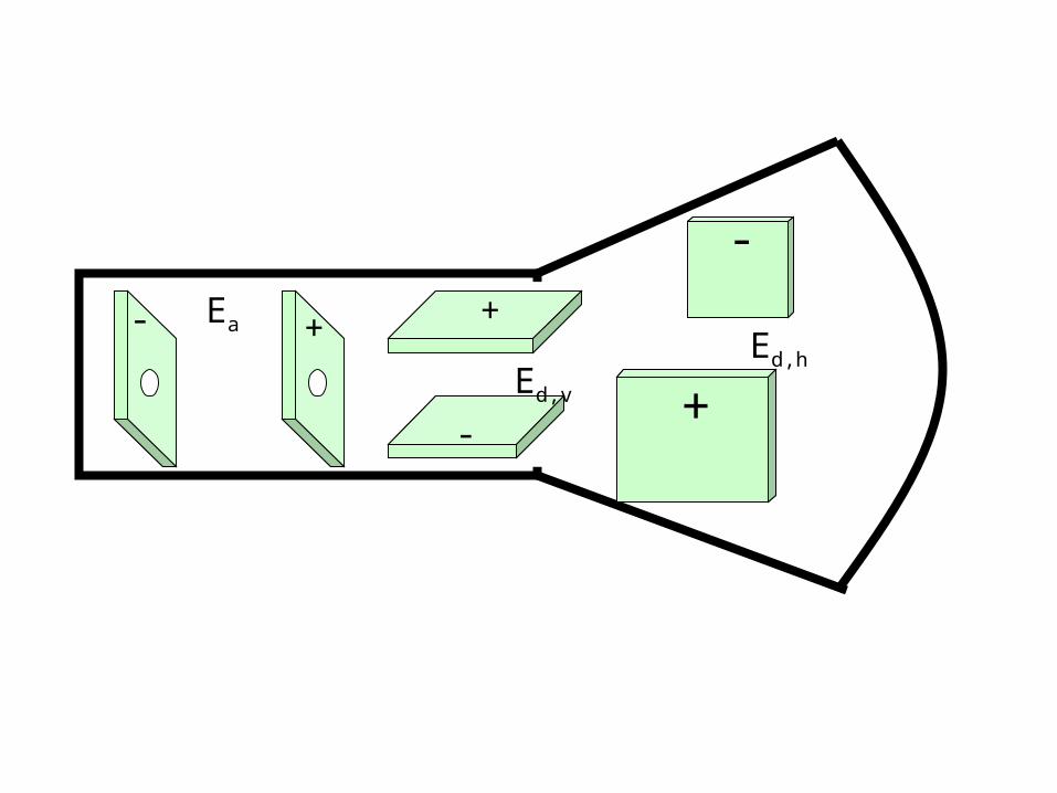
Ea
Ed,v
Ed,h
- +
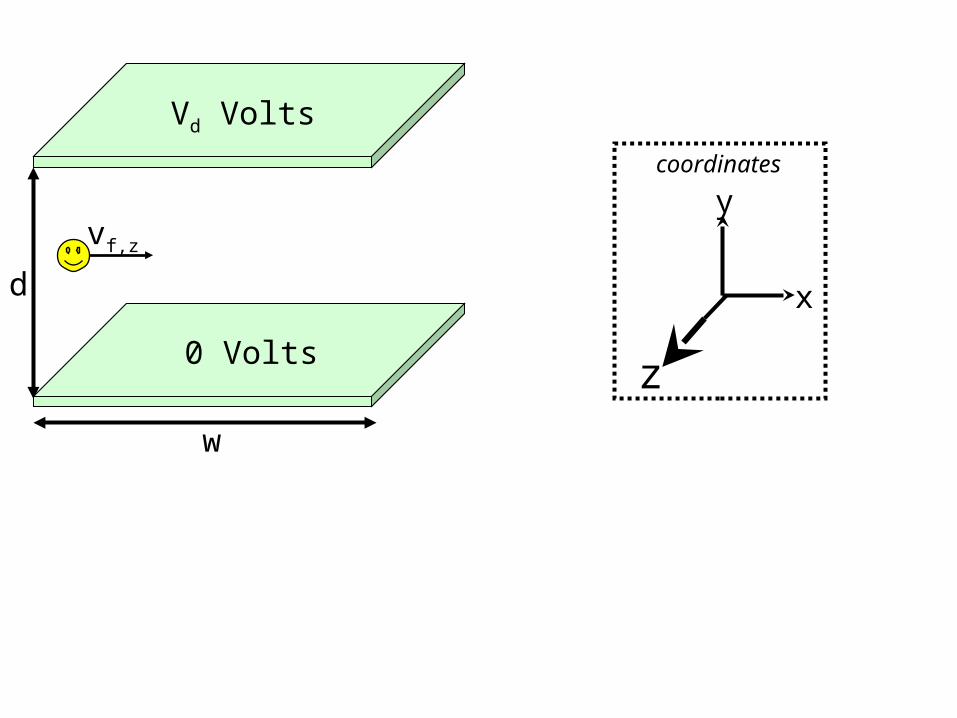
Vd Volts
0 Volts
d
w
vf,z
x
ycoordinates
z
x
y
coordinates
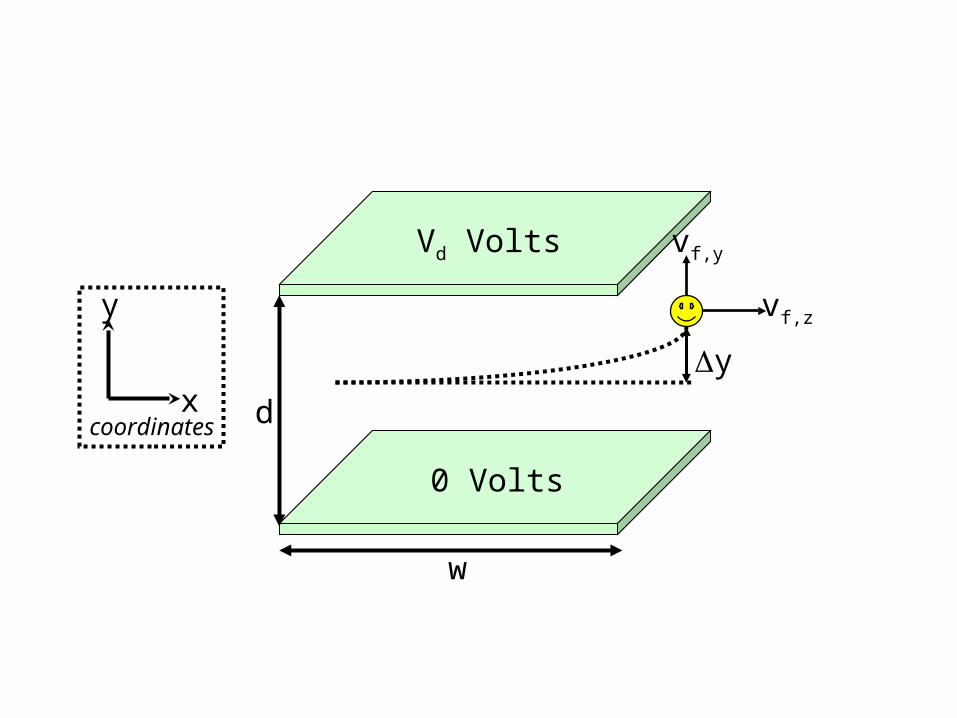
Vd Volts
0 Volts
d
w
vf,z
vf,y
y
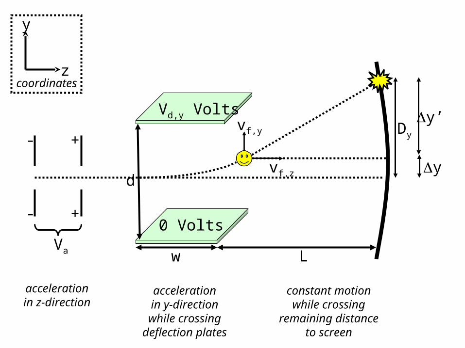
Vd,y Volts
0 Volts
d
w
z
y
coordinates
vf,z
vf,y
y
-
-
+
+
Va L
y’Dy
accelerationin z-direction
accelerationin y-direction
while crossingdeflection plates
constant motionwhile crossing
remaining distanceto screen
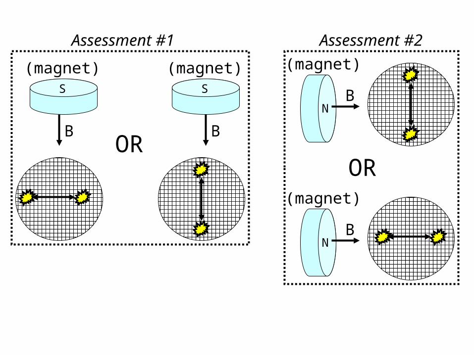
S
(magnet)
B
S
(magnet)
BOR
N
(magnet)
B
N
(magnet)
B
OR
Assessment #1 Assessment #2
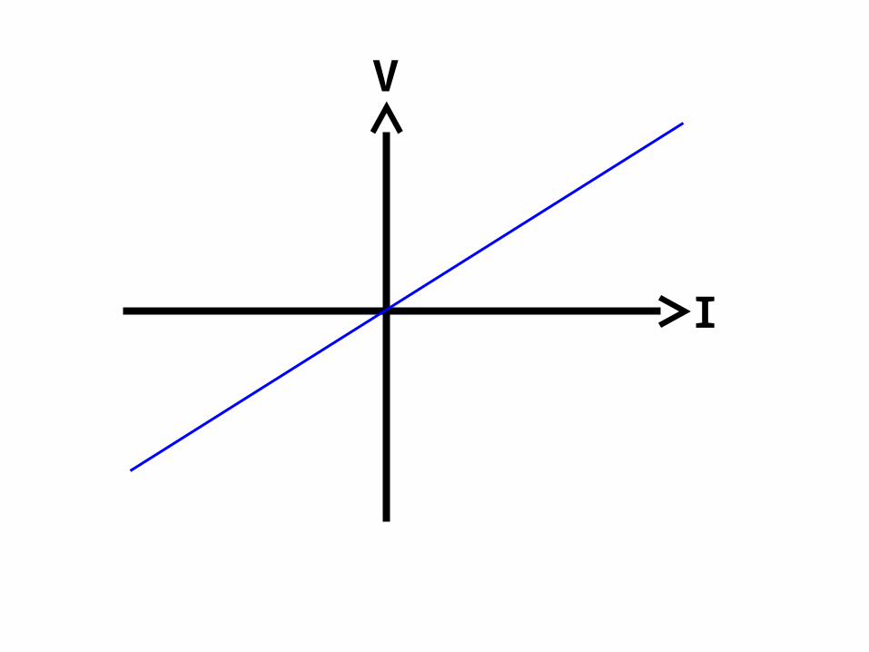
I
V
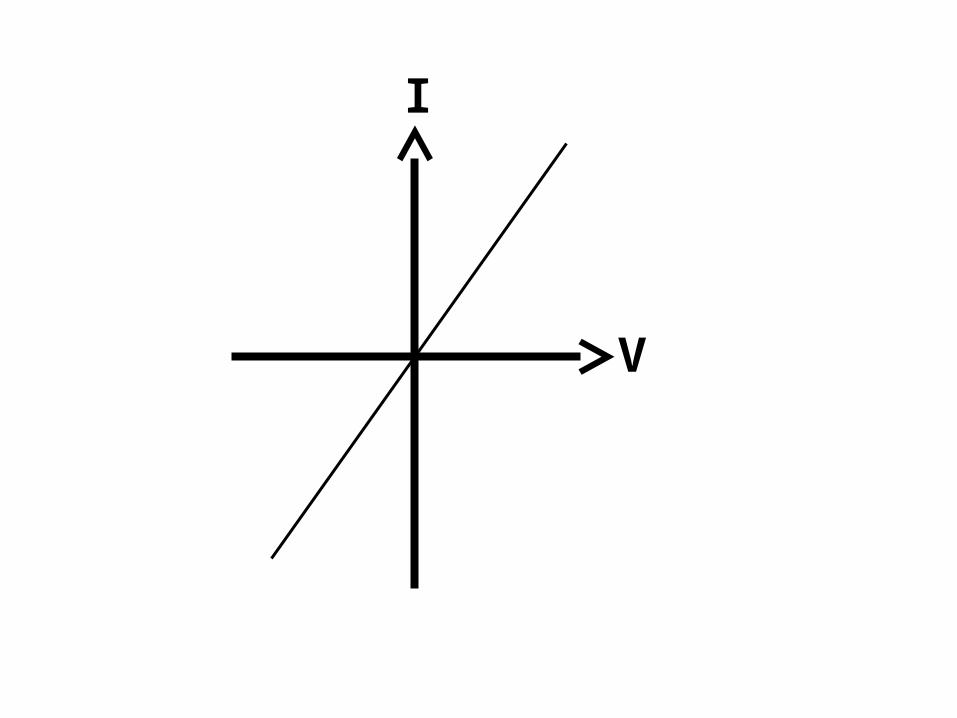
I
V
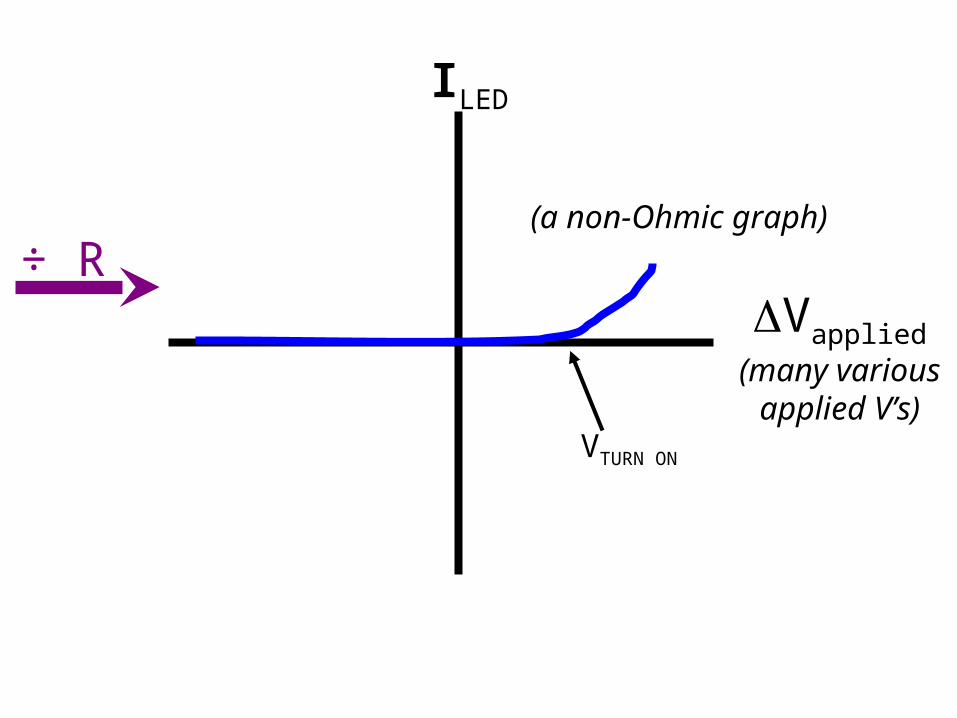
ILED
Vapplied(many variousapplied V’s)
(a non-Ohmic graph)
VTURN ON
÷ R
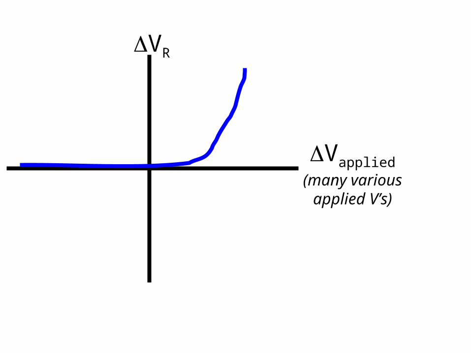
VR
Vapplied(many variousapplied V’s)
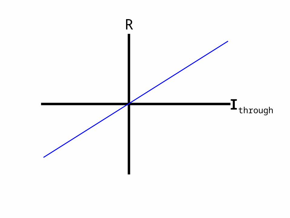
Ithrough
R
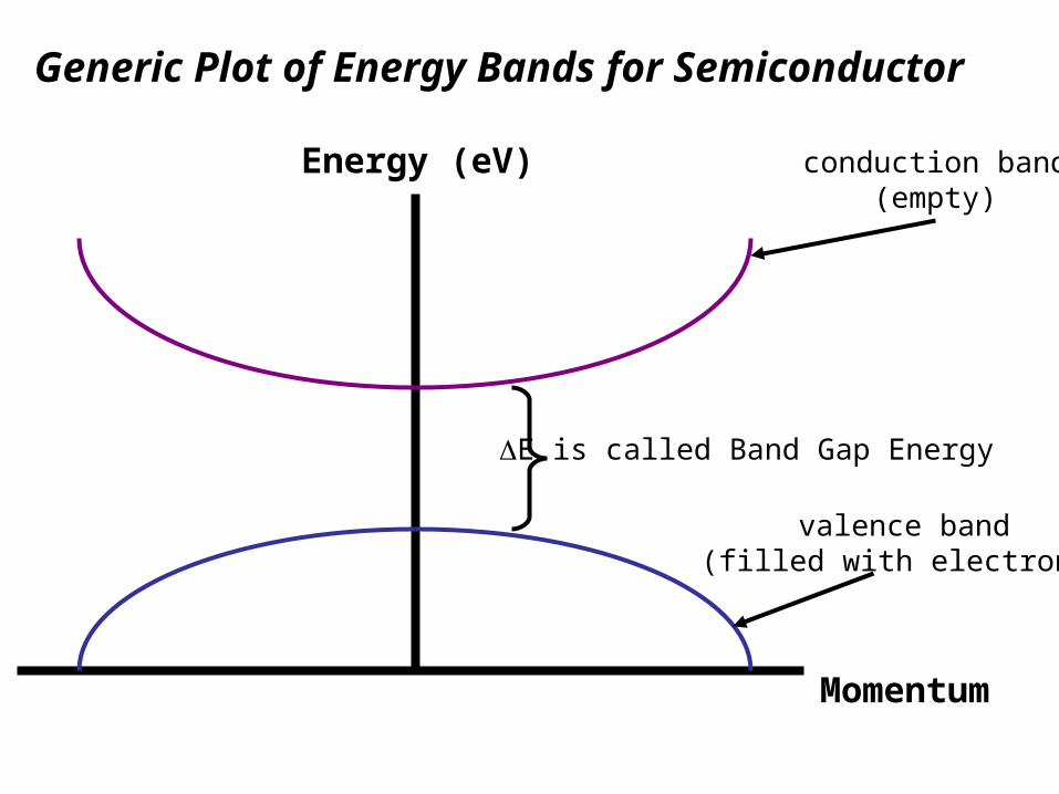
Energy (eV)
Momentum
Generic Plot of Energy Bands for Semiconductor
conduction band(empty)
valence band(filled with electrons)
E is called Band Gap Energy
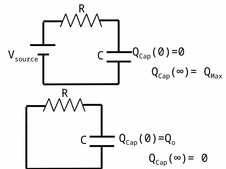
C
R
VsourceQCap(0)=0
QCap(∞)= QMax
C QCap(0)=Qo
R
QCap(∞)= 0
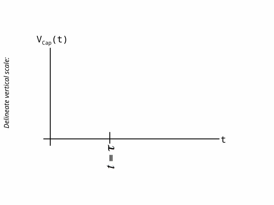
t
VCap(t)
Del
inea
te v
ertic
al s
cale
:
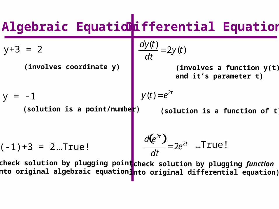
Algebraic Equation Differential Equation
y+3 = 2
dy(t)
dt2y(t)
(involves a function y(t)and it’s parameter t)
(involves coordinate y)
y = -1(solution is a point/number) (solution is a function of t)
y(t) e2t
(-1)+3 = 2 …True!
(check solution by plugging point into original algebraic equation)
(check solution by plugging function into original differential equation)
d e2t dt
2e2t …True!

![+1cm[width=30mm]logo.pdf +1cm Corporate Frauds: Factors … · 2020-02-13 · Sohail Rizwan (PM 123012) Dr. Sisira Colombage Federation University, Melbourne, Australia Dr. Nirosha](https://img.pdfslide.us/doc/110x75/5fb289900444c87054516422/1cmwidth30mmlogopdf-1cm-corporate-frauds-factors-2020-02-13-sohail-rizwan.jpg)


![+1cm[width=30mm]logo.pdf +1cm MHD Tangent Hyperbolic ... Qamar.pdf · CERTIFICATE OF APPROVAL MHD Tangent Hyperbolic Nano uid Past a Stretching Sheet with the E ect of Joule Heating](https://img.pdfslide.us/doc/110x75/5d57042188c99392138b8fe5/1cmwidth30mmlogopdf-1cm-mhd-tangent-hyperbolic-qamarpdf-certificate.jpg)


![+1cm[width=30mm]logo.pdf +1cm Numerical Simulations of](https://img.pdfslide.us/doc/110x75/627ae62ce8953d6de617a9b4/1cmwidth30mmlogopdf-1cm-numerical-simulations-of-.jpg)


![+1cm[width=30mm]logo.pdf +1cm Encryption Schemes Based on](https://img.pdfslide.us/doc/110x75/62738cd6244a866096606ae8/1cmwidth30mmlogopdf-1cm-encryption-schemes-based-on-.jpg)


![+1cm[width=30mm]logo.pdf +1cm Evaluation of Water](https://img.pdfslide.us/doc/110x75/627cce9ad7cf13078b01c655/1cmwidth30mmlogopdf-1cm-evaluation-of-water-.jpg)