Embed Size (px)
Citation preview

PDH Star | T / F: (833) PDH-STAR (734-7827) | E: [email protected]
E-056 Industrial Systems Protection Instructor: Velimir Lackovic Course ID: E-056 PDH Hours: 3 PDH

E-056 Industrial Systems Protection
1
INDUSTRIAL SYSTEM PROTECTION
Development of industrial and commercial electrical power systems has also introduced
the requirements for their improved reliability. The possible outage time costs have also
dramatically increased. The introduction of automation systems into industry and
commerce requires application of advanced power system automation in order to enhance
overall reliability and efficiency. Careful attention has to be given to the protection and
control of industrial electrical supply systems. Many technologies that have been developed
for EHV electrical systems may be used in lower voltage systems but usually on a reduced
scale. Nevertheless, industrial electrical systems have many particular issues that need
special attention and the development of custom solutions. Many industrial systems have
their own generation. Sometimes it is used only in emergency situations, supplying a
limited number of buses and with limited capacity. This design is frequently used to ensure
safe shutdown of process plant and personnel safety. However, in some plants, processes
allow generation of a substantial quantity of electricity, allowing surplus export to the grid.
Industrial plants that operate power generation in parallel with the utility grid are usually
referred to as cogeneration or embedded generation. Particular protection design may be
needed for the point of common coupling between the private and utility grid. Industrial
systems usually comprise many cable feeders and transformers and special protection
arrangements may be also required for them.
BUSBAR ARRANGEMENT
The system busbar arrangement is apparently very important, and it can be quite complex
for very large industrial systems. Nevertheless, in most industrial systems a single busbar
divided into sections by a bus-section circuit breaker is typical. This configuration is shown
in Figure 1. Main and standby drives for particular process equipment will be supplied
from switchboard separate sections, or sometimes from different switchboards.
E-056 Industrial Systems Protection
2
Figure 1. Common switchboard arrangement for an industrial plant
The main system design condition is that electrical network single outages within the plant
will not cause simultaneous loss of both the main and standby drives. Analyzing a medium
sized industrial supply system, presented in Figure 2 it will be noted that not only duplicate
supplies and transformers are used, but also few important loads are separated and
supplied from ‘Essential Services Board(s)’ (usually known as ‘Emergency’ boards). This
allows maximum utilization of the standby generator equipment. A standby generator is
typically of the turbocharged diesel-driven type. On loss of incoming supply detection at
any switchboard with an emergency section, the generator is automatically started. The
adequate circuit breakers will close once the generator is up to speed and rated voltage to
recover supply to the Essential Services affected switchboard sections. For a common
diesel generator set, the emergency supply would be available within 10-20 seconds from
the start sequence command being released.
HV supply 1
Transformer 1
HV supply 2
Transformer 2
2 out of 3 mechanical or
electrical interlock

E-056 Industrial Systems Protection
3
Figure 2. Common industrial power system
NO
NC C
*
NO
* NO
A B 0.4 kV
NC *
NO
NO A B
A B C
6 kV
0.4 kV
0.4 kV *
NO NC
NO
B A C
*
NO
A B 6 kV
NO
*
110 kV
33 kV
Bus section C – Essential supplies EDG – Emergency generator * - Two out of three interlock
EDG

E-056 Industrial Systems Protection
4
The Essential Services Boards are installed to supply equipment that is essential for the
secure shut down, limited operation or plant preservation and for the staff safety. This will
cover process drives that are needed for safe shutdown, venting systems, UPS loads
supplying emergency lighting, process control computers, etc. The emergency generator
may vary in size from a single unit rated 20-30kW in a small plant up to several units of 2-
10MW in a large oil refinery. Big financial trading institutions may also have standby power
demands of few MW to keep computer systems.
DISCRIMINATION
Protection equipment operates in conjunction with switchgear. For a common industrial
system, feeders and plant will be typically protected by different circuit breakers and by
fused contactors. Circuit breakers will have their overcurrent and ground fault relays. A
contactor may also be installed with a protection device (e.g. motor protection), but
associated fuses are supplied to break fault currents surpassing the contactor interrupting
capability. The rating of fuses and selection of protection relay settings is completed to
ensure that discrimination is accomplished – i.e. the ability to select and isolate only the
faulty part of the system.
HRC FUSES
The protection element nearest to the actual point of power utilisation is probably the fuse
or a system of fuses. It is important that attention is provided to the correct fuse
application. The HRC fuse is a key fault clearance device for industrial and commercial
system protection. It can be installed in a distribution fuse board or as part of a contactor
or fuse-switch. The second is looked at as a crucial part of LV circuit protection, combining
safe circuit making and breaking with an isolating capability accomplished in conjunction
with the HRC fuse reliable short circuit protection. Fuses combine the characteristics of
economy and reliability. These factors are vital for industrial applications. HRC fuses stay
consistent and stable in their breaking characteristics without calibration and
maintenance. This is one of the major factors for keeping fault clearance discrimination.

E-056 Industrial Systems Protection
5
Lack of discrimination through improper fuse grading will end in unnecessary supply
disconnection. However, if both the major and minor fuses are properly designed HRC
devices this will not endanger staff or cables associated with the plant.
FUSE CHARACTERISTICS
The time needed for melting the fusible element is dependent on the current magnitude.
This time is known as the fuse ‘pre-arcing’ time. Element vaporization happens on melting
and there is fusion between the vapor and the filling powder resulting in quick arc
extinction. Fuses have a valuable feature known as ‘cut-off’. It is presented in Figure 3.
When an unprotected circuit is exposed to a short circuit fault, the r.m.s. current increases
towards a ‘prospective’ (or maximum) value. The fuse typically breaks the short circuit
current before it can reach the prospective value. This happens in the first quarter to half
cycle of the short circuit. The increasing current is broken by the fusible element melting,
subsequently dying away to zero during the arcing period.
Figure 3. HRC fuse cut-off characteristic
Since the electromagnetic forces on busbars and connections conducting short circuit
current are proportional to the square of the current, it will be noted that ‘cut-off’
significantly decreases the mechanical forces generated by the fault current and which may
Curve of asymmetrical prospective short-circuit current
Current trace
Arcing time
Time
IP
1 cycle
Start of short circuit
Pre-arcing time
Total clearance time

E-056 Industrial Systems Protection
6
distort the busbars and connections if not properly rated. A common example of ‘cut-off’
current feature is presented in Figure 4. It is possible to use this feature during the project
design stage to select equipment with a lower fault withstand rating downstream of the
fuse. This may save money, but adequate documentation and maintenance controls are
needed to ensure that only replacement fuses with very similar features are used
throughout the plant lifetime – otherwise a safety hazard may happen.
Figure 4. Common fuse cut-off current features
DISCRIMINATION BETWEEN FUSES
Fuses are typically installed in series and it is vital that they are able to discriminate with
each other at all current levels. Discrimination is achieved when the bigger (‘major’) fuse
stays unaffected by fault currents that are cleared by the smaller (‘minor’) fuse. The fuse
operating time can be looked at in two parts:
- the time needed for fault current to melt the element, known as the ‘pre-arcing time’
- the time needed by the arc generated inside the fuse to extinguish and isolate the
circuit, known as the ‘arcing time’
The total energy released in a fuse during its operation consists of ‘pre-arcing energy’ and
‘arc energy’. The values are typically shown in terms of I2t, where I is the current flowing
0.1
1
10
100
0.1 0.2 0.4 0.8 1.6 3.2 6.4 12.8 25.6 51.2 102.4
Cut off current 2A 6A 16A
25A 35A 50A 80A
125A 200A 400A 500A
E-056 Industrial Systems Protection
7
through the fuse and t is the time in seconds. Presenting the quantities in this way provides
an assessment of the heating effect that the fuse imposes on related equipment during its
operation under fault conditions. To achieve positive discrimination between fuses, the
total I2t value of the minor fuse must not surpass the pre-arcing I2t value of the major fuse.
In reality, this means that the major fuse will have to have a rating considerably higher than
that of the minor fuse, and this may increase discrimination problems. Commonly, the
major fuse must have a rating of at least 160% of the minor fuse for discrimination to be
achieved.
PROTECTION OF CABLES BY FUSES
PVC cable can be loaded to its full nominal rating only if it has ‘close excess current
protection’. This degree of protection can be provided by means of a fuse link having a
‘fusing factor’ not surpassing 1.5, where:
- Fusing factor = Minimum Fusing Current/Current Rating Cables made using other
insulating materials (e.g. paper, XLPE).
AMBIENT TEMPERATURE EFFECT
High ambient temperatures can affect HRC fuses capability. Most fuses are suited for
application in ambient temperatures up to 35°C, but for some fuse ratings, derating may be
required at higher ambient temperatures. Manufacturers' documentation should be
consulted for the de-rating factors.
MOTOR PROTECTION
The manufacturers' documentation should also be consulted when fuses are to be used for
motor circuits. In this case, the fuse gives short circuit protection but must be chosen to
withstand the starting current (roughly up to 8 times full load current), and also
continuously transfer the normal full load current without deterioration. Tables of
recommended fuse sizes for both ‘direct on line’ and ‘assisted start’ motor configurations
are typically provided.
E-056 Industrial Systems Protection
8
INDUSTRIAL CIRCUIT BREAKERS
Some industrial power system parts are most effectively protected by HRC fuses, but the
replacement of blown fuse links can be especially difficult in some situations. In these
plants, circuit breakers are used instead. The breaker is required to successfully break the
maximum possible fault current without damage to itself. In addition to fault current
interruption, the breaker must rapidly release the resulting ionized gas away from the
breaker contacts, to stop arc re-striking. The breaker, its cable or busbar connections, and
the breaker housing, must all be made to withstand the mechanical stress resulting from
the magnetic fields and internal arc gas pressure generated by the highest levels of fault
current. The circuit breaker types that are most frequently installed in industrial system
are described in the following paragraphs.
MINIATURE CIRCUIT BREAKERS (MCBS)
MCBs are small circuit breakers, both in physical size but more importantly, in ratings. The
basic single pole element is a small, manually closed, electrically or manually opened
switch planed in a moulded plastic casing. They are suited for use on 230V AC. single-
phase/400V AC three-phase systems and for DC auxiliary supply systems, with current
ratings of up to 125A. Thermal element is contained within each unit in which a bimetal
strip will operate the switch when excessive current goes through it. This element works
with a predetermined inverse-time/current characteristic. Greater currents, commonly
those surapssing 3-10 times rated current, trip the circuit breaker without intentional
delay by actuating a magnetic trip overcurrent element. The MCB operating time
characteristics are not adjustable. European Standard EN 60898-2 determines the
instantaneous trip characteristics, while the manufacturer can define the inverse time
thermal trip characteristic. Hence, a common tripping characteristic does not exist. The
maximum AC breaking current allowed by the standard is 25kA. Single-pole elements may
be mechanically coupled in groups to make 2, 3 or 4 pole units, when needed. The available
ratings make MCBs appropriate for industrial, commercial or domestic installations, for
protecting equipment such as cables, lighting and heating circuits, and also for the low
power motor circuits control and protection. They may be installed instead of fuses on

E-056 Industrial Systems Protection
9
individual circuits, and they are typically ‘backed-up’ by a device of higher fault
interrupting capacity. Different accessory units, such as isolators, timers, and under-voltage
or shunt trip release elements may be combined with an MCB to suit the particular circuit.
When personnel or fire protection is needed, a residual current device (RCD) may be
combined with the MCB. The RCD contains a miniature core balance current transformer
that embraces all of the phase and neutral conductors to give sensitivity to ground faults
within a common range of 0.05% to 1.5% of rated current, dependent on the installed RCD.
The core balance CT supplies a common magnetic trip actuator for the MCB assembly. It is
also feasible to get current-limiting MCBs. These types open prior to the prospective fault
current being achieved. Hence, they have similar properties to HRC fuses. It is claimed that
the additional initial cost is outweighed by lifetime savings in replacement costs after a
fault has happened, plus the benefit of providing improved protection against electric
shock. As a result of the enhanced safety given by MCBs equipped with an RCD device, they
are tending to replace fuses, particularly in new installations.
MOULDED CASE CIRCUIT BREAKERS (MCCBS)
These circuit breakers are very similar to MCBs but have the following crucial differences:
- the maximum ratings are greater, with voltage ratings up to 1000V AC/1200V DC.
Current ratings of 2.5kA continuous/180kA r.m.s break can be accomplished,
dependent upon power factor.
- the breakers are bigger, commensurate with the level of ratings. Even though
available as single, double or triple pole units, the multiple pole units have a
common housing for all the poles. Where installed, the switch for the neutral circuit
is typically a separate device, coupled to the multi-pole MCCB.
- the operating levels of the magnetic and thermal protection devices may be
adjustable, especially in the bigger MCCBs

E-056 Industrial Systems Protection
10
- because of their bigger ratings, MCCBs are typically installed in the power
distribution system closer to the power source than the MCBs
- the adequate European specification is EN 60947-2. Attention must be taken in the
MCCB short-circuit ratings.
MCCBs are provided with two breaking capacities, the higher of which is its ultimate
breaking capacity. The importance of this is that after breaking such a current, the MCCB
may not be fit for extended use. The lower, or service, short circuit breaking capacity allows
extended use without further detailed examination of the device. The standard allows a
service breaking capacity of as little as 25% of the ultimate breaking capacity. While there
is no problem to use of MCCBs to break short-circuit currents between the service and
ultimate values, the inspection needed after such a trip decreases the device usefulness.
Clearly, it is also difficult to decide if the fault current magnitude was in excess of the
service rating. Some MCCBs are equipped with microprocessor-controlled programmable
trip features providing a wide range of such characteristics. Time–delayed overcurrent
features may not be the same as the standard characteristics for dependent-time protection
described in IEC 60255-3. Therefore, discrimination with other protection must be
carefully considered. There can be issues where two or more MCBs or MCCBs are
connected in series, as obtaining selectivity between them may be difficult. There may be a
demand that the major device should have a rating of k times the minor device to allow
discrimination. The manufacturer should be consulted for k values. Careful examination of
manufacturers’ documentation is always needed at the design stage to determine any such
limitations that may be imposed by MCCB particular makes and types.
AIR CIRCUIT BREAKERS (ACBS)
Air circuit breakers are typically encountered on industrial systems rated at 3.3kV and
below. Modern LV ACBs can be found in current ratings of up to 6.3kA with maximum
breaking capacities in the range of 85kA-120kA r.m.s., depending on system voltage. This
breaker type functions on the principle that the arc generated when the main contacts open

E-056 Industrial Systems Protection
11
is controlled by directing it into an arc chute. In this case, the arc resistance is increased
and the current is decreased to the point where the circuit voltage cannot keep the arc.
Therefore the current decreases to zero. To help in the quenching of low current arcs, an
air cylinder may be connected to each pole to direct a blast of air across the contact faces as
the breaker opens. This will also reduce contact erosion. Industrial air circuit breakers are
typically withdrawable and are made with a flush front plate. Therefore, they are ideal for
inclusion together with fuse switches and MCBs/MCCBs in modular multi-tier distribution
switchboards. This approach helps to maximize the number of circuits within a given floor
area. Older types using a manual or dependent manual closing mechanism are considered
as a safety hazard. This arises under conditions of closing the CB when a fault exists on the
circuit being controlled. During the close-trip service, there is a danger of arc egress from
the CB casing, with a risk of injury to the operator. Such types should be replaced with
modern equivalents. ACBs are typically equipped with integral overcurrent protection,
therefore avoiding the need for separate protection elements. Nevertheless, the operating
time characteristics of the integral protection are typically designed to make discrimination
with MCBs/MCCBs/fuses easier. Therefore, they may not be in line with the standard
dependent time characteristics presented in IEC 60255-3. Hence, co-ordination problems
with discrete protection relays may still happen, but modern numerical protection relays
have more flexible characteristics to alleviate such problems. ACBs will also have facilities
for accepting an external trip signal, and this can be used in conjunction with an external
protection relay. Figure 5 presents the common tripping characteristics.

E-056 Industrial Systems Protection
12
Figure 5. Common ACB tripping characteristics
OIL CIRCUIT BREAKERS (OCBS)
Oil circuit breakers have been popular for many years for industrial supply systems at
voltages of 3.3kV and above. They are found as both ‘bulk oil’ and ‘minimum oil’ models.
Their only major difference is the volume of oil in the tank. In this breaker type, the main
contacts are placed in an oil filled tank, with the oil acting as the both the insulation and the
arc-quenching medium. The arc generated during contact separation under fault conditions
creates dissociation of the hydrocarbon insulating oil into hydrogen and carbon. The
hydrogen extinguishes the arc. The generated carbon mixes with the oil. Since the carbon is
conductive, the oil must be replaced after a prescribed number of fault clearances, when
the contamination degree reaches an unacceptable level. Because of the fire risk involved
Very inverse
Normal inverse
Extremely inverse

E-056 Industrial Systems Protection
13
with oil, precautions such as the construction of fire/blast walls may have to be taken when
OCBs are used.
VACUUM CIRCUIT BREAKERS (VCBS)
In recent years, vacuum circuit breakers, along with CBs using SF6, have replaced OCBs for
new installations in industrial/commercial systems at voltages of 3.3kV and above.
Compared with oil circuit breakers, vacuum breakers do not introduce fire risk and they
have high reliability with long maintenance free periods. A variation is the vacuum
contactor with HRC fuses, used in HV motor starter applications.
SF6 CIRCUIT BREAKERS
In some countries, circuit breakers with SF6 gas as the arc quenching medium are
preferred to VCBs as the replacement for air- and oil-insulated CBs. Some modern
switchgear cubicles types allow the installation of either VCBs or SF6- insulated CBs
according to customer demands. Ratings of up to 31.5kA r.m.s. fault break at 36kV and
40kA at 24kV are common. SF6-insulated CBs also have benefits of reliability and
maintenance intervals compared to air- or oil-insulated CBs. They are of similar size to
VCBs for the same rating.
PROTECTION RELAYS
When the circuit breaker does not have integral protection, then an appropriate external
relay will have to be used. For an industrial system, the typical protection relays are time-
delayed overcurrent and ground fault relays.

E-056 Industrial Systems Protection
14
CT connections
Phase elements
Residual current elements
System Fault type
Notes
(a)
3Ph.3W Line-line Peterson coil and unearthed systems
(b) 3Ph.3W (i)Line-line (ii)Line-ground
(c) 3Ph.4W (i)Line-Line (ii)Line-ground (iii)Line-neutral
Ground fault protection only if ground fault current is not less than twice primary operating current
(d) 3Ph.3W (i)Line-Line (ii)Line-ground
Phase elements must be in same phases at all stations. Ground fault settings may be less than full load
(e) 3Ph.3W (i)Line-line (ii)Line-ground
Ground fault settings may be less than full load
(f) 3Ph.4W (i)Line-Line (ii)Line-ground (iii)Line-neutral
Ground fault settings may be less than full load but must be greater than largest Ph.-N load
(g)
3Ph.4W (i)Line-line (ii)Line-ground (iii)Line-neutral
Ground fault settings may be less than full load
B A C
B A C
B A C
B A C
N B A C

E-056 Industrial Systems Protection
15
CT connections
Phase elements
Residual current elements
System Fault type
Notes
(h)
3Ph.3W Or 3Ph.4W
(i)Line-ground
Ground fault settings may be less than full load
Ph. – phase, W – wire, E – earth, N – neutral
Figure 6. Overcurrent and ground fault relay connections
Typically, for three wire systems, overcurrent protection relays have been applied to two
phases only for relay element economy. Even up until the last generation of static
protection relays, economy was still a consideration in terms of the number of analogue
current inputs that were provided. Two overcurrent devices can be installed to detect any
interphase short circuit, so it was conventional to use two elements on the same phases at
all relay locations. The phase CT residual current connections for ground fault relay
element are unaffected by such convention. Figure 6 presents the possible relay
arrangements and settings limitations.
CO-ORDINATION ISSUES
There are a number of issues that typically happen in industrial and commercial networks.
They are covered in the following paragraphs.
N B A C
E-056 Industrial Systems Protection
16
GROUND FAULT PROTECTION WITH RESIDUALLY-CONNECTED CTS
For four-wire arrangements, the residual connection of three phase CTs to ground fault
relay element will provide ground fault protection, but the ground fault relay element must
be set above the highest single-phase load current to avoid nuisance tripping. Harmonic
currents (which may sum in the neutral conductor) may also end in spurious tripping. The
ground fault relay element will also react to a line-neutral fault for the line that is not
covered by an overcurrent element where only two overcurrent elements are used. Where
it is needed that the ground fault protection responds only to ground fault current, the
protection device must be residually connected to three phase CTs and to a neutral CT or to
a core balance CT. In this situation, overcurrent protection must be applied to all three lines
to ensure that all line-neutral faults will be discovered by overcurrent protection. Installing
a CT in the neutral grounding connection to drive ground fault protection relay provides
ground fault protection at the source of supply for a 4- wire system. If the neutral CT is
omitted, neutral current is seen by the relay as ground fault current and the relay setting
would have to be increased to stop tripping under normal load conditions.
When the ground fault protection relay is driven from residually connected CTs, the
protection relay current and time settings must be such that that the protection will be
stable during the passage of transient CT spill current through the protection relay. Such
spill current can run in the case of transient, asymmetric CT saturation during the passage
of offset fault current, inrush current or motor starting current. The nuisance tripping risk
is higher with the deployment of low impedance electronic protection relays rather than
electromechanical ground fault relays which presented major relay circuit impedance.
Energizing a protection relay from a core balance type CT typically enables more sensitive
settings to be obtained without the nuisance tripping risk with residually installed phase
CTs. When this method is used in a four-wire system, it is mandatory that both the line and
neutral conductors are passed through the core balance CT aperture. For a 3-wire system,
attention has to be taken with the cable sheath arrangement, otherwise cable faults
involving the sheath may not end in relay operation (Figure 7.).

E-056 Industrial Systems Protection
17
FOUR-WIRE DUAL-FED SUBSTATIONS
The co-ordination of ground fault relays that are used to protect four-wire systems
demands special consideration in the case of low voltage, dual-fed arrangements. Problems
in reaching optimum protection for typical arrangements are presented below.
Figure 7. CBCT connection for four-wire system (a) Incorrect installation (b) Correct
I >
No operation
I >
Operation
Cable box
I >
Cable gland
Cable gland / sheath ground connection

E-056 Industrial Systems Protection
18
installation
USE OF 3-POLE CBS
When both neutrals are grounded at the transformers and all circuit breakers are of the 3-
pole type, the neutral busbar in the switchgear forms a double neutral to ground
connection, as presented in Figure 8. In the case of an uncleared feeder ground fault or
busbar ground fault, with both the incoming supply breakers closed and the bus section
breaker open, the ground fault current will split between the two ground connections.
Ground fault relay RE2 may operate, tripping the supply to the healthy section of the
switchboard as well as relay RE1 tripping the supply to the faulted section.
Figure 8. Dual fed four-wire systems: use of 3-pole CBs
In the case, only one incoming supply breaker is closed, the ground fault relay on the
energized side will detect only a proportion of the fault current running in the neutral
busbar. This not only significantly increases the relay operating time but also decreases its
sensitivity to low-level ground faults. The solution to this problem is to use 4-pole CBs that
switch the neutral as well as the three phases. Then there is only a single ground fault path
and relay operation is not compromised.
IF/2 IF/2
IF
Supply 1 Supply 2
IF
Bus section CB
IF/2 RE1 RE2
IF/2

E-056 Industrial Systems Protection
19
APPLICATION OF SINGLE GROUND ELECTRODE
A configuration sometimes used with four-wire dual-fed substations where only a 3-pole
bus section CB is used is to use a single ground electrode connected to the mid-point of the
neutral busbar in the switchgear, as presented in Figure 9. When operating with both
incoming main circuit breakers and the bus section breaker closed, the bus section breaker
must be opened first should the ground fault happen, in order to achieve discrimination.
The co-ordination time between the ground fault relays RF and RE should be made at fault
level F2 for a substation with both incoming supply breakers and bus section breaker
closed.
Figure 9. Dual fed four-wire systems: application of single point neutral grounding
When the substation is operated with the bus section switch closed and either one or both
of the incoming supply breakers closed, it is possible for unbalanced neutral busbar load
current to operate relay RS1 and/or RS2 and trip the incoming breaker. Interlocking the trip
circuit of each RS relay with typically closed auxiliary contacts on the bus section breaker
I >
RS1
I > RS2
F2
I > RF
Supply 2 Supply 1
F1
I >
RE
N

E-056 Industrial Systems Protection
20
can stop this. Nevertheless, should a ground fault happen on one side of the busbar when
relays RS are already operated, it is possible for a contact race to happen. When the bus
section breaker opens, its break contact may close before the RS relay trip contact on the
healthy side can reset. Increasing the pick-up level of protection relays RS1 and RS2 above
the maximum unbalanced neutral current may stop the tripping of both supply breakers.
Nevertheless, the best option is to use 4-pole circuit breakers, and independently earth
both sides of the busbar. If, during a busbar ground fault or uncleared feeder ground fault,
the bus section breaker fails to open when needed, the interlocking break auxiliary contact
will also be inoperative. This will stop protection relays RS1 and RS2 from functioning and
providing back-up protection, with the result that the fault must be cleared by slower
phase overcurrent protection relays. An optional method of finding back-up protection
could be to install a second relay RE, in series with protection relay RE, having an operation
time set longer than that of protection relays RS1 and RS2. But since the extra relay must be
set to trip both of the incoming supply breakers, back-up protection would be
accomplished but busbar selectivity would be lost.
INDUCTION MOTOR FAULT CURRENT CONTRIBUTION
When an industrial system has motor loads, the motors will contribute fault current for a
limited time. They contribute to the total fault current via the following mechanism. When
an induction motor is operating, a flux, created by the stator winding, rotates at
synchronous speed and interacts with the rotor. If a big reduction in the stator voltage
happens for any reason, the motor flux cannot instantaneously change and the machine
mechanical inertia will tend to inhibit speed reduction over the first few cycles of fault
duration. The trapped flux in the rotor produces a stator voltage initially equal to the back
e.m.f. induced in the stator before the fault and decaying. This is determined according to
the X/R ratio of the related flux and current paths. Therefore, the induction motor acts as a
generator resulting in a contribution of current whose AC and DC components
exponentially decay. Typical 50Hz motor AC time constants lie in the range 10ms-60ms for
LV motors and 60-200ms for HV motors. This motor contribution has often been ignored in
the fault level calculations.

E-056 Industrial Systems Protection
21
Industrial systems typically have a large motor load component, so this approach is not
correct. Motor contributions to the total fault current may well be a major fraction of the
total. Standards relating to fault level calculations, such as IEC 60909, demand that the
motor contribution effect is included. Standards discuss the situations under which this
should be done, and the calculation method to be used. Guidance is given on common
motor fault current contribution for both HV and LV motors if the needed information is
not known. Hence, it is now relatively easy, using adequate calculation software, to
calculate the magnitude and duration of the motor contribution which enables a more
accurate evaluation of the fault level for:
- relay co-ordination discrimination
- calculation of the needed switchgear/busbar fault rating
For protection calculations, motor fault level contribution is generally not an urgent issue.
In industrial systems, fault clearance time is typically assumed to happen at 5 cycles after
fault occurrence, and at this time, the motor fault level contribution is much less than just
after fault occurrence. In rare situations, it may have to be taken into account for correct
time grading for through-fault protection considerations, and in the peak voltage
calculation for high impedance differential protection configurations.
It is more important to take motor contribution into account when considering equipment
fault rating (busbars, cables, switchgear, etc.). Typically, the initial AC motor current
component at the instant of fault is of similar magnitude to the direct-on-line motor
starting current. For LV motors, 5xFLC is assumed as the common fault current
contribution (after considering the effect of motor cable impedance), with 5.5xFLC for HV
motors, unless it is known that low starting current HV motors are installed. It is also
common that similar motors connected to a busbar can be lumped together as one
equivalent motor. In doing so, motor rated speed may need to be considered, as 2 or 4 pole
motors have a longer fault current decay than motors with a higher number of poles. The
kVA rating of the single equivalent motor is taken as the sum of the kVA ratings of the
individual motors. It is still possible for motor contribution to be ignored in situations

E-056 Industrial Systems Protection
22
where the motor load on a busbar is insignificant in comparison to the total load (again IEC
60909 gives guidance in this respect). Nevertheless, big LV motor loads and all HV motors
should be considered when calculating fault levels.
AUTOMATIC CHANGEOVER SYSTEMS
Induction motors are typically used to drive critical loads. In some plants, such as those
involving the pumping of fluids and gases, this has led to the need for a power supply
control configuration in which motor and other loads are automatically transferred on loss
of the normal supply to an optional supply. A fast changeover, allowing the motor load to
be re-accelerated, decreases the possibility of a process trip happening. Such configurations
are typically used for big generating units to transfer unit loads from the unit transformer
to the station supply/start-up transformer. When the normal supply fails, induction motors
that stay connected to the busbar slow down and the trapped rotor flux creates a residual
voltage that exponentially decays. All motors connected to a busbar will start to decelerate
at the same rate when the supply is lost if they stay connected to the busbar. This happens
because the motors will exchange energy between themselves, so that they tend to stay
‘synchronised’ to each other. Consequently, the residual voltages of all the motors decay at
nearly the same rate. The magnitude of this voltage and its phase displacement with
respect to the healthy alternative supply voltage is a function of time and the motor speed.
The angular displacement between the residual motor voltage and the incoming voltage
will be 180° at some instant. If the healthy back-up supply is switched on to motors which
are running down under these conditions, very high inrush currents may happen,
generating stresses which could be of adequate magnitude to cause mechanical stress, as
well as a severe dip in the back-up supply voltage.
Two automatic transfer methods are applied:
- in-phase transfer system
- residual voltage system

E-056 Industrial Systems Protection
23
The in-phase transfer method is presented in Figure 10(a). Normal and standby feeders
from the same power source are used.
Phase angle measurement is applied to discover the relative phase angle between the
standby feeder voltage and the motor busbar voltage. When the voltages are in phase or
just prior to this condition, a high speed circuit breaker is used to complete the transfer.
This approach is restricted to big high inertia drives where the gradual run down
characteristic upon loss of normal feeder supply can be accurately anticipated. Figure
10(b) presents the residual voltage method, which is more typical, particularly in the
petrochemical industry. Two feeders are used, feeding two busbar sections connected by a
normally open bus section breaker. Each line is capable of transferring the total busbar
load. Each bus section voltage is monitored and loss of supply on either section causes the
relevant incomer CB to open. Given there are no protection operations to show the
presence of a busbar fault, the bus section breaker is automatically closed to restore the
supply to the unpowered busbar section of after the residual voltage created by the motors
running down on that section has decreased to a an acceptable level.

E-056 Industrial Systems Protection
24
Figure 10. Auto-transfer systems (a) In phase transfer approach (b) Residual voltage
approach
This is between 25% and 40%, of nominal voltage, dependent on the power system
characteristics. The residual voltage setting selection will affect the re-acceleration current
M M M M
Feeder No.1 Feeder No.2
Ursd< Ursd<
M
Preferred feeder
Standby feeder
Phase angle relay
φ< High
speed CB

E-056 Industrial Systems Protection
25
after the bus section breaker closes. For example, a setting of 25% may be anticipated to
result in an inrush current of around 125% of the starting current at full voltage.
Optionally, a time delay could be used as a residual voltage measurement substitute, which
would be set with knowledge of the plant to make sure that the residual voltage would
have sufficiently decreased before transfer is started. The protection relay settings for the
switchboard must take account of the total load current and the voltage dip during the re-
acceleration period in order to avert spurious tripping during this time. This time can be
few seconds where big inertia HV drives are used.
VOLTAGE AND PHASE REVERSAL PROTECTION
Voltage protection relays have been widely used in industrial power supply systems. The
principle detects under-voltage and/or overvoltage conditions at switchboards and
disconnects supplies before damage happens. Continued overvoltage may create damage to
voltage-sensitive devices (e.g. electronics), while under-voltage may create excessive
current to be taken by motor loads. Motors are equipped with thermal overload protection
to avert excessive current damage, but under-voltage protection is typically used to
disconnect motors after a prolonged voltage dip. With a voltage dip made by a source
system fault, a group of motors could decelerate to such a degree that their aggregate
reacceleration currents might keep the recovery voltage depressed to a level where the
motors might stall. Modern numerical motor protection relays usually contain voltage
protection functions, therefore removing the need for discrete under-voltage protection
relays. Previous installations may still utilize discrete under-voltage protection relays, but
the setting criteria stay the same.
Reverse phase sequence voltage protection should be used where it may be difficult for a
motor to be started with rotation in the opposite direction. Incorrect rotation due to
reverse phase sequence might be set up following error after power system maintenance
or repairs. Older motor control switchboards might have been equipped with discrete
protection relays to discover this condition. Modern motor protection relays may use this
function. If reverse phase sequence is discovered, motor starting can be stopped. If reverse

E-056 Industrial Systems Protection
26
phase sequence voltage protection is not given, the high-set negative phase sequence
current protection in the protection relay would promptly discover the condition once the
starting device is closed – but motor initial reverse rotation could not be stopped.
POWER FACTOR CORRECTION AND CAPACITOR PROTECTION
Loads such as induction machines take substantial reactive power from the supply system.
This may end with poor power factor. The reactive power flow increases the voltage drops
through series reactances such as transformers and reactors. It takes some of the power
system plant current carrying capacity and it increases the power system resistive losses.
To offset the losses and restrictions in plant capacity, utilities typically apply tariff penalties
to big industrial or commercial customers for running their plant at low power factor.
Therefore, the customer is stimulated to improve the system power factor and it may be
efficient to install fixed or variable power factor correction equipment. These devices will
increase or regulate the plant power factor. Shunt capacitors are typically used to improve
power factor. The basis for reactive power compensation is presented in Figure 11, where
<φ1 represents the uncorrected power factor angle and <φ2 the angle relating to the
desired power factor.

E-056 Industrial Systems Protection
27
Figure 11. Power factor correction method
The following may be concluded from this vector diagram:
𝑈𝑈𝑈𝑈𝑈𝑈𝑈𝑈𝑈𝑈𝑈𝑈𝑈𝑈𝑈𝑈𝑈𝑈𝑈𝑈𝑈𝑈 𝑝𝑝𝑈𝑈𝑝𝑝𝑈𝑈𝑈𝑈 𝑓𝑓𝑓𝑓𝑈𝑈𝑈𝑈𝑈𝑈𝑈𝑈 = 𝑘𝑘𝑘𝑘𝑘𝑘𝑘𝑘𝑘𝑘1
= cos∠𝜑𝜑1
𝐶𝐶𝑈𝑈𝑈𝑈𝑈𝑈𝑈𝑈𝑈𝑈𝑈𝑈𝑈𝑈𝑈𝑈 𝑝𝑝𝑈𝑈𝑝𝑝𝑈𝑈𝑈𝑈 𝑓𝑓𝑓𝑓𝑈𝑈𝑈𝑈𝑈𝑈𝑈𝑈 = 𝑘𝑘𝑘𝑘𝑘𝑘𝑘𝑘𝑘𝑘2
= cos∠𝜑𝜑2
𝑅𝑅𝑈𝑈𝑈𝑈𝑅𝑅𝑈𝑈𝑈𝑈𝑅𝑅𝑈𝑈𝑈𝑈 𝑅𝑅𝑈𝑈 𝑘𝑘𝑘𝑘𝑘𝑘 = 𝑘𝑘𝑘𝑘𝑘𝑘1 − 𝑘𝑘𝑘𝑘𝑘𝑘2
If the kW load and uncorrected power factors are known, then the capacitor rating to
accomplish a given degree of correction may be computed from:
𝐶𝐶𝑓𝑓𝑝𝑝𝑓𝑓𝑈𝑈𝑅𝑅𝑈𝑈𝑈𝑈𝑈𝑈 𝑘𝑘𝑘𝑘𝑘𝑘𝑈𝑈 = 𝑘𝑘𝑘𝑘 × (tan∠𝜑𝜑1 − tan∠𝜑𝜑2)
V kW
Com
pens
atin
g kV
Ar
Cap
acito
r kVA
r M
agne
tisin
g kV
Ar
φ1 φ2

E-056 Industrial Systems Protection
28
A spreadsheet can easily be made to compute the required amount of compensation to
accomplish a desired power factor.
CAPACITOR CONTROL
Where the plant load or the plant power factor drastically changes, it is mandatory to
control the power factor correction. Otherwise, over-correction will end in excessive
system voltage and unnecessary losses. In several industrial systems, capacitors are
manually switched in when needed, but automatic controllers are standard practice. A
controller gives automatic power factor correction, by comparing the running power factor
with the target power factor. Based on the available groupings, an adequate amount of
capacitance is switched in or out to keep an optimum average power factor. The controller
is equipped with a ‘loss of voltage’ relay element to make sure that all selected capacitors
are instantaneously disconnected if there is a supply voltage interruption. When the supply
voltage is fixed, the capacitors are progressively reconnected as the plant starts up. To
make sure that capacitor groups degrade at approximately the same rate, the controller
typically rotates selection or randomly chooses groups of the same size in order to even out
the connected time. The installation of overvoltage protection to trip the capacitor bank is
also needed in particular applications. This would be to stop a serious system overvoltage if
the power factor correction (PFC) controller fails to take quick corrective action. The PFC
design must recognize that many industrial loads create harmonic voltages, with the result
that the PFC capacitors may sink substantial harmonic currents. A harmonic study may be
required to decide the capacitor thermal ratings or whether series filters are needed.
MOTOR P.F. CORRECTION
When dealing with motor load power factor correction, group correction is not the most
economical method. Some industrial consumers use capacitors to chosen motor
substations rather than using all of the correction at the main incoming substation busbars.
Frequently, power factor correction may even be applied to individual motors, ending in
optimum power factor being achieved under all conditions of aggregate motor load. In
some situations, the improvement in the voltage regulation can also improve motor

E-056 Industrial Systems Protection
29
starting. Motor capacitors are usually six-terminal units, and a capacitor may be installed
directly across each motor phase winding. Capacitor sizing is crucial, such that a leading
power factor does not happen under any load condition. If extra capacitance is applied to a
motor, it may be possible for self-excitation to happen when the motor is switched off or
experiences a supply failure. This can result in the generation of a high voltage or in
mechanical damage if there is a sudden supply restoration. Since most star/delta or auto-
transformer starters involve a transitional break in supply, it is typically suggested that the
capacitor rating should not surpass 85% of the motor magnetizing reactive power.
CAPACITOR PROTECTION
When considering capacitor protection, provision should be made for the transient inrush
current happening on switch-on, since this can reach peak values of around 20 times
normal current. Capacitor switchgear is typically substantially de-rated to allow for this.
Inrush currents may be fixed by a resistor in series with each capacitor or capacitor banks.
Protection equipment is needed to stop rupture of the capacitor due to an internal fault and
also to protect the cables and related devices from damage in case of a capacitor failure. If
fuse protection is contemplated for a three-phase capacitor, HRC fuses should be used with
a current rating of not less than 1.5 times the rated capacitor current. Medium voltage
capacitor banks can be protected by the configuration presented in Figure 13. Since
harmonics increase capacitor current, the protection relay will react more correctly if it
does not have in-built tuning for harmonic rejection. Double star capacitor banks are used
at medium voltage. As presented in Figure 12, a current transformer in the inter star-point
connection can be used to drive a protection relay to discover the out-of-balance currents
that will run when capacitor elements become short-circuited or open-circuited. The
protection relay will have adjustable current settings, and it might have a bias circuit,
supplied from an external voltage transformer, that can be adjusted to compensate for
steady-state spill current in the inter star-point connection.

E-056 Industrial Systems Protection
30
Figure 12. Double star capacitor bank protection
Some industrial loads such as arc furnaces require large inductive components and
correction is usually provided using very large, high voltage capacitors in different
arrangements. Another high voltage capacitor arrangement is the ‘split phase’
configuration where the elements making up each phase of the capacitor are separated into
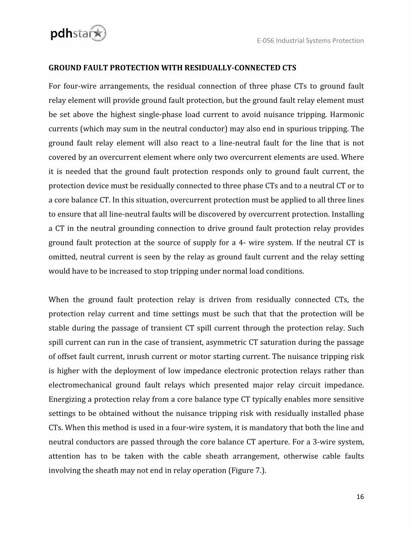
two parallel paths. Figure 14 presents two possible relay connection arrangements. A
differential protection relay can be used with a current transformer for each parallel
branch. The protection relay compares the current in the split phases, using sensitive
current settings but also adjustable compensation for the unbalance currents arising from
initial capacitor mismatch.
Relay
Trip Alarm
A
C
B
Capacitor bank

E-056 Industrial Systems Protection
31
Figure 13. Capacitor bank protection
U> U<
Metering
I >
ΔI>>
I >
ΔI>>
I >
ΔI>>
Capacitor bank
Metering
Id>
P2
P1
11 kV
From incoming transformer
PFC/V Controller
Lockout
I>> I >> I> I >
E-056 Industrial Systems Protection
32
Figure 14. Split phase capacitor bank differential protection
EXAMPLES
In next paragraphs, examples of the industrial system protection are presented.
FUSE CO-ORDINATION
Fuse application example is based on the configuration presented in Figure 15(a). This
presents an unsatisfactory configuration with frequently encountered shortcomings. It can
be noted that fuses B, C and D will discriminate with fuse A but the 400A sub-circuit fuse E
may not discriminate, with the 500A sub-circuit fuse D at higher levels of fault current.
A
I >
B
I >
C
I >
Alarm Trip
Alarm Trip
C
I >
B
I >
A
I >

E-056 Industrial Systems Protection
33
Figure 15. Fuse protection: effect of layout on discrimination (a) Incorrect applications
increasing discrimination problem in (b) Correct application and discrimination
Rating 400 A
E
Rating 100 A
B
Rating 500 A
C
Rating 500 A
D
Rating 30 A
F F F F
Rating 1000 A
Rating 500 A
B
Rating 500 A
C
Rating 500 A
D
Rating 400 A
E F F F
Rating 1000 A
F
Rating 30A each

E-056 Industrial Systems Protection
34
The solution, presented in Figure 15(b), is to supply the 400A circuit E direct from the
busbars. The sub-circuit fuse D may now have its rating decreased from 500A to a value, of
approximately 100A, adequate to the remaining sub-circuit. This configuration now gives a
satisfactory discriminating fuse distribution scheme. Nevertheless, there are industrial
applications where discrimination is a secondary issue. In the application presented in
Figure 16, a contactor having a fault rating of 20kA controls the load in one sub-circuit. A
fuse rating of 630A is chosen for the minor fuse in the contactor circuit to provide
protection within the contactor through-fault capacity.
Figure 16. Back-up protection example
The major fuse of 800A is selected, as the minimum rating that is higher than the total load
current on the switchboard. Discrimination between the two fuses is not achieved, as the
pre-arcing I2t of the 800A fuse is less than the total I2t of the 630A fuse. Hence, the major
fuse will blow as well as the minor one, for most faults so that all other loads supplied from
the switchboard will be lost. This may be allowable in some situations. Nevertheless, in
most situations loss of the complete switchboard for a fault on a single outgoing circuit will
not be acceptable, and the design will have to be changed.
630 A
Fused contactor
Auxiliary circuits
800 A
400 V

E-056 Industrial Systems Protection
35
FUSES/MCCBS/OVERCURRENT RELAYS GRADING
Configuration example involving a moulded case circuit breaker, fuse and a protection
relay is presented in Figure 17. A 1MVA 3.3kV/400V transformer supplies the LV board via
a circuit breaker, which is equipped with numerical relay that has a setting range of 8-
400% of rated current and supplied from 2000/1A CTs.
Figure 17. Protection co-ordination example network diagram– fuse/MCCB/relay
Discrimination is needed between the protection relay and both the fuse and MCCB up to
the 40kA fault rating of the board. To start with, the time/current characteristics of both
the 400A fuse and the MCCB are printed in Figure 18.
1 MVA
3300/415 V
Fuse 400 A
MCCB 400 A
LV board fault level=30kA
2000/1 A
I>> I>

E-056 Industrial Systems Protection
36
Figure 18. Fuse/MCCB/relay grading curves
DETERMINATION OF RELAY CURRENT SETTING
The selected relay current setting must not be lower than the full load current level and
must have sufficient margin to allow the relay to reset with full load current running. Full
load current can be calculated from the transformer rating:
𝐹𝐹𝐶𝐶𝐹𝐹 =𝑘𝑘𝑘𝑘𝑘𝑘
𝑘𝑘𝑘𝑘 × √3=
10000.4 × √3
= 1443 𝑘𝑘
Fuse
MCCB Relay

E-056 Industrial Systems Protection
37
With the CT ratio of 2000/1A and a protection relay reset ratio of 95% of the nominal
current setting, a current setting of at least 80% would be sufficient, to avoid tripping
and/or failure to reset with the transformer transferring full load current. Nevertheless,
value selection at the lower end of this current setting range would shift the relay
characteristic towards that of the MCCB and discrimination may be lost at low fault
currents. Hence, it is prudent to initially choose a protection relay current setting of 100%.
RELAY CHARACTERISTIC AND TIME MULTIPLIER SELECTION
An EI characteristic is chosen for the protection relay to ensure discrimination with the
fuse. From Figure 18, it may be noted that at the fault level of 40kA the fuse will operate in
less than 0.01s and the MCCB operates in roughly 0.014s. Applying a fixed grading margin
of 0.4s, the demanded relay operating time becomes 0.4 + 0.014 = 0.414s. With a CT ratio of
2000/1A, a protection relay current setting of 100%, and a protection relay TMS setting of
1.0, the extremely inverse curve provides a relay operating time of 0.2s at a fault current of
40kA. This is too fast to provide sufficient discrimination and shows that the EI curve is too
severe for this application. Turning to the VI protection relay characteristic, the relay
operation time is around 0.71s at a TMS of 1.0. To reach the demanded relay operating time
of 0.414s:
𝑇𝑇𝑇𝑇𝑇𝑇 𝑠𝑠𝑈𝑈𝑈𝑈𝑈𝑈𝑅𝑅𝑈𝑈𝑠𝑠 = 0.4140.71
= 0.583
Use a TMS of 0.6, nearest possible setting. The use of a different form of inverse time
characteristic makes it advisable to verify discrimination at the lower current levels also at
this stage. At a fault current of 4kA, the protection relay will trip in 8.1s, which does not
provide discrimination with the MCCB. A protection relay operation time of 8.3s is needed.
To resolve this, the protection relay characteristic has to be moved away from the MCCB
characteristic, a modification that may be accomplished by using a TMS of 0.625. The
revised protection relay characteristic is also presented in Figure 18.

E-056 Industrial Systems Protection
38
DUAL-FED SUBSTATION PROTECTION
Numerical protection relays can be used in an industrial system. Consider the common
large industrial substation presented in Figure 19. Two 1.6MVA, 11/0.4kV transformers
supplying a busbar whose bus-section CB is typically open. The LV system is solidly
grounded. The largest outgoing feeder is to a motor rated 160kW, 193kVA, and a starting
current of 7 x FLC.
The transformer impedance is to IEC standards. The LV switchgear and bus bars are fault
rated at 50kA rms. To simplify the assessment, only the phase-fault LV protection is looked
at.
Figure 19. Dual-fed switchboard relay grading example
Relay A
NO 2500/1
Trip
I>> I>
Relay B
1.6 MVA 11/0.4 kV Z=6.25%
Trip
300/1
A2 0.4 kV 50 kA rms
2500/1 I>> I>
Relay C2
M
2500/1 Relay C1 I>> I> Trip
A1
Motor cable
160 kW
I>>

E-056 Industrial Systems Protection
39
GENERAL CONSIDERATIONS
Assessment of many substations organized as in Figure 19 indicates that the maximum
fault level and feeder load current is got with the bus-section circuit breaker closed and one
of the infeeding CBs open. This is valid so long as the switchboard has a considerable
amount of motor load. The motor load contribution to the switchboard fault level is
typically higher than that from a single infeeding transformer, since the transformer
restricts the amount of fault current infeed from the primary side. The three-phase break
fault level at the switchboard under these conditions is assumed to be 40kA rms. Relays C
do not need to have directional characteristics as all three circuit breakers are only
momentarily closed during transfer from a single infeeding transformer to two infeeding
transformers arrangement. This transfer is typically an automated sequence, and the
chance of a fault happening during the short period (of the order of 1s) when all three CBs
are closed is taken to be negligibly small. Even though this arrangement gives the highest
fault level at the switchboard, it is not considered from either a switchboard fault rating or
protection viewpoint. It is assumed that modern numerical protection relays are installed.
For simplicity, a fixed grading margin of 0.3s is applied.
MOTOR PROTECTION RELAY SETTINGS
From the provided motor characteristics, the overcurrent protection relay settings (Relay
A) can be found as follows:
Thermal element:
- current setting: 300A
- time constant: 20 mins
Instantaneous element:
- current setting: 2.32kA
These are the only settings relevant to the upstream protection relays.

E-056 Industrial Systems Protection
40
RELAY B SETTINGS
Relay B settings are found from consideration of the loading and fault levels with the bus-
section breaker between busbars A1 and A2 closed. No data is provided about the load split
between the two busbars, but it can be assumed in the absence of definitive information
that each busbar is capable of feeding the total load of 1.6MVA. With fixed tap transformers,
the bus voltage may decrease to 95% of nominal under these conditions, leading to a load
current of 2430A. The IDMT current setting must be higher than this, to avert relay
operation on normal load currents and with aggregate starting/re-acceleration currents. If
the complete load on the busbar was motor load, an aggregate starting current in excess of
13kA would happen, but a current setting of this order would be too high and lead to
further upstream grading problems. It is unlikely that the complete load is motor load
(though this does happen, especially where a supply voltage of 690V is selected for motors
– an increasingly typical practice) or that all motors are simultaneously started (but
simultaneous re-acceleration may well happen). What is basic is that protection relay B
does not issue a trip command under these conditions – i.e. the protection relay
current/time characteristic is in excess of the current/time characteristic of the worst-case
starting/reacceleration condition. Therefore, it is assumed that 50% of the total bus load is
motor load, with an average starting current of 600% of full load current (= 6930A), and
that re-acceleration takes 3s. Therefore, a current setting of 3000A is initially applied. The
SI characteristic is used for grading the protection relay, as coordination with fuses is not
needed. The TMS is needed to be set to grade with the thermal protection of protection
relay A under ‘cold’ conditions, as this provides the longest operation time of Relay A, and
the re-acceleration conditions. A TMS value of 0.41 is found to give satisfactory grading,
being dictated by the motor starting/re-acceleration transient. Adjustment of both current
and TMS settings may be needed depending on the exact re-acceleration circumstances.
Note that lower current and TMS settings could be applied if motor starting/reacceleration
did not need to be considered.
E-056 Industrial Systems Protection
41
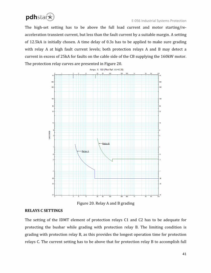
The high-set setting has to be above the full load current and motor starting/re-
acceleration transient current, but less than the fault current by a suitable margin. A setting
of 12.5kA is initially chosen. A time delay of 0.3s has to be applied to make sure grading
with relay A at high fault current levels; both protection relays A and B may detect a
current in excess of 25kA for faults on the cable side of the CB supplying the 160kW motor.
The protection relay curves are presented in Figure 20.
Figure 20. Relay A and B grading
RELAYS C SETTINGS
The setting of the IDMT element of protection relays C1 and C2 has to be adequate for
protecting the busbar while grading with protection relay B. The limiting condition is
grading with protection relay B, as this provides the longest operation time for protection
relays C. The current setting has to be above that for protection relay B to accomplish full

E-056 Industrial Systems Protection
42
co-ordination, and a value of 3250A is suitable. The TMS setting using the SI characteristic
is selected to grade with that of protection relay B at a current of 12.5kA (protection relay B
instantaneous setting), and is found to be 0.45. The high-set element must grade with that
of protection relay B, so a time delay of 0.62sec is needed. The current setting must be
greater than that of relay B, so use a value of 15kA. The final protection relay grading
curves and settings are presented in Figure 21.
Parameter Value Parameter Value Parameter Value Parameter Value
Relay A Ith 300A Time const. 1200s I>> 2320A Tinst 0 Relay B I> 2500A TMS 0.175 I>> 12500A Tinst 0.32s Relay C I> 2750A TMS 0.25 I>> 15000 Tinst 0.62s
Figure 21. Final relay grading curves

E-056 Industrial Systems Protection
43
COMMENTS ON GRADING
While the above grading may seem satisfactory, the transformer primary side protection
has not been assessed. IDMT protection at this point will have to grade with protection
relays C and with the transformer and cabling through-fault short-time withstand curves.
This may end in overly long operation times. Even if the operation time at the 11kV level is
acceptable, there is probably a utility infeed to consider, which will require an additional
set of protection relays and another stage of time grading, and the fault clearance time at
the utility infeed will almost certainly be excessive. One solution is to allow a total supply
loss to the 0.4kV bus under conditions of a single infeed and bus section CB closed. This is
accomplished by setting protection relays C such that grading with protection relay B does
not happen at all current levels, or omitting protection relay B from the protection
configuration. The argument for this is that network operation policy is to ensure loss of
supply to switchboard both sections does not happen for single contingencies. As single
infeed operation is not normal, a contingency has already happened, so that an additional
fault causing total supply loss to the switchboard through tripping of one of protection
relays B is a second contingency. Therefore, total loss of supply is acceptable. The
alternative is to allow a lack of discrimination at some point on the system. Another
solution is to use partial differential protection to remove the requirement for Relay A, but
this is rarely used. The used strategy will depend on the particular conditions.