Embed Size (px)
Citation preview

DYNE™
© 2009 Duro Dyne Corp.Printed in USA 1/2009
BD030405
®Duro Dyne East Division, Bay Shore, NY 631-249-9000 Fax: 631-249-8346Duro Dyne Midwest Division, Fairfield, OH 513-870-6000 Fax: 513-870-6005Duro Dyne West Division, Santa Fe Springs, CA 562-926-1774 Fax: 562-926-5778Duro Dyne Canada, Lachine, Quebec, Canada 514-422-9760 Fax: 514-636-0328
www.durodyne.com E-mail: [email protected]
RECOMMENDAtiONS & PRECAUtiONSRECOMMENDAtiONS & PRECAUtiONS
tEStiNGtEStiNG All Dyna-Tites have been independently tested to five times their allowable working load by
one or more of the following independent laboratories:
RADCO inc, Long Beach CA SMACNA testing and Research institute New York testing Laboratories Underwriters Laboratories
All Dyna-Tites have been tested to UL 1598 and are listed under File# E246601.
LISTEDLuminaire Fitting14HE
Dyna-tite Product Catalog Page 7
As a matter of sound engineering practice, the Dyna-Tite assembly must be located no closer than 12 inches to the suspension point. In the case of round duct, where the wire rope encircles the duct, the Dyna-Tite must be located the distance of one diameter from the duct wall. Adherence to these minimum clearances will distribute the load the most efficiently among all duct hanging components.
tO ENSURE HANGiNG SYStEM iNtEGRitY AND SAFEtY: Use only Duro Dyne wire rope. tO FACiLitAtE HEiGHt ADjUStMENt: Install the object low and adjust it upwards to the desired level.
DO NOt ExCEED tHE WORkiNG LOAD LiMit (WLL) OF tHE PRODUCt: Each product is load rated and incorporates a minimum safety factor of 5:1. This WLL takes into account the specification criteria of the Dyna-Tite Cable Lock and the wire rope.
DO NOt USE ON COAtED WiRE ROPE: It is important to maintain the metal to metal contact between the lock-ing wedges in the Dyna-Tite and the wire rope.
DO NOt APPLY PAiNt OR OtHER COAtiNG: to any part of the assembly as these may impair the free move-ment of the locking wedges inside the Dyna-Tite Cable Lock.
DO NOt APPLY LUBRiCANt: to any part of the assembly as this will alter the surface nature of the wire rope and attract dirt and debris.
DO NOt USE FOR LiFtiNG: (UnDEr Hook sLIngs) This product is designed for static load applications only.
kEEP tHE PRODUCt CLEAN AND FREE FROM DiRt: Any dirt should be removed from the product prior to assembly.
iNSPECt PERiODiCALLY: Upon inspection, discard and replace if worn, distorted, or damaged.
REMOvE DAMAGED WiRE ENDS: Using a designated pair of wire rope cutters prior to inserting into the Dyna-Tite Cable Lock.
DYNA-titE StARtER kitDYNA-titE StARtER kitThe starter kit has everything you need to get started. iNCLUDES: 1 Roll of 3/32’’ Cable 100 CL12 Cable Locks 1 Custom Cable Counter Lid and Bucket 1 Cable Cutter
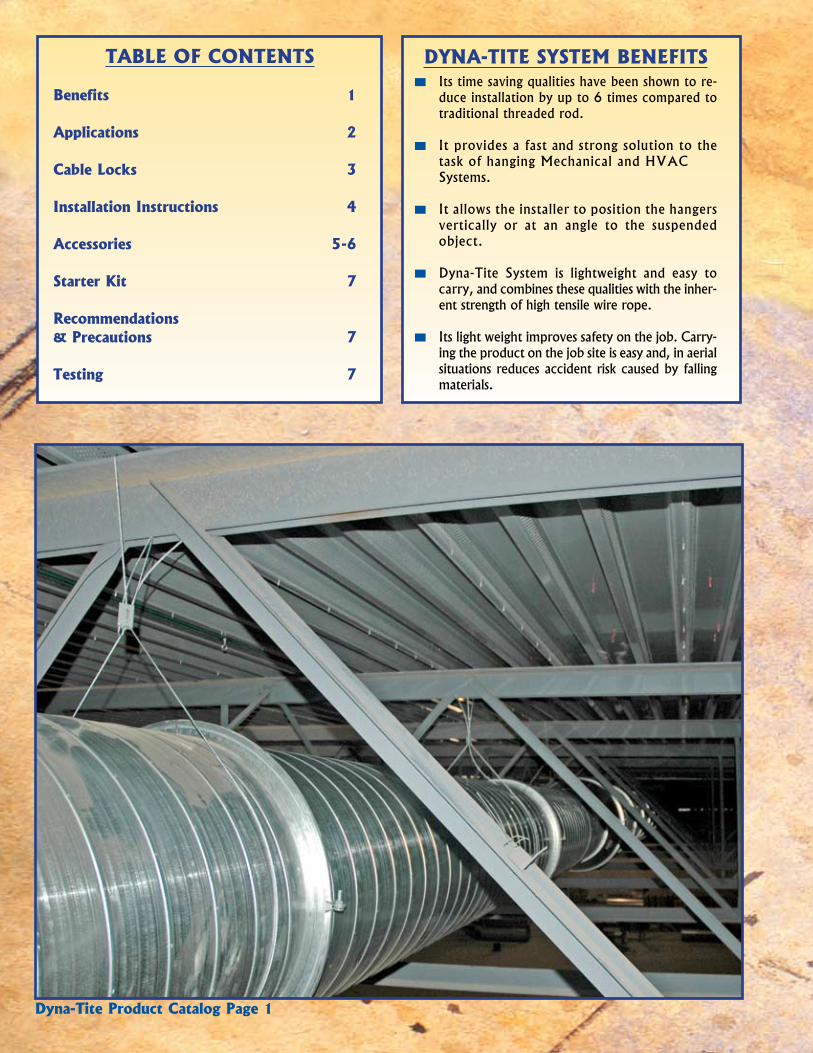
tABLE OF CONtENtS
Benefits 1
Applications 2
Cable Locks 3
installation instructions 4
Accessories 5-6
Starter kit 7
Recommendations & Precautions 7
testing 7
item # Code Description Qty
30220 DDg3W Eye Bolt & nut (3/8’’-16 x 2-1/2’’)
100/Box
item # Code Description Qty
894075 0690Tn Cable Cutter 1
Cable Cutter When cutting wire cable it is important to use a recognized wire cable
cutter such as the Duro Dyne cutter detailed here. This will ensure that the form of the rope is maintained prior to insertion in the Dyna-Tite.
safety Catch 3/16” Cutting Capacity spring Loaded For Ease of Use 5” Long Handles For High Leverage Hardened steel Blades For Durability Vinyl Coated Handles For Comfortable, non-slip grip
DYNA-titE ACCESSORiESDYNA-titE ACCESSORiES
Custom Cable CounterThe CCC1 makes preparing for your duct hanging project a lot simpler. Take an
empty five gallon bucket, put a spool of wire rope in the bottom, put in some boxes of Dyna-Tite cable locks and a cable cutter. Place the CCC1 on top of the bucket and you are ready for the job site.
At the job site remove the cable lock boxes and the wire cutter, thread the wire rope through the CCC1 measuring device and you are ready to hang ductwork. Just pull the wire rope to the length needed, cut it and reset the counter.
Counter displays from 0 feet 0 inches to 9999 feet and 11 inches Push Button reset Designed For Use With Duro Dyne Wire rope Fits most 5 gallon buckets Lightweight
item # Code Description Qty
30390 CCC1 Custom Cable Counter 1
Eye Bolt & Nut
Dyna-tite Product Catalog Page 6
DYNA-titE SYStEM BENEFitS Its time saving qualities have been shown to re-
duce installation by up to 6 times compared to traditional threaded rod.
It provides a fast and strong solution to the task of hanging Mechanical and HVAC
systems.
It allows the installer to position the hangers vertically or at an angle to the suspended object.
Dyna-Tite system is lightweight and easy to carry, and combines these qualities with the inher-ent strength of high tensile wire rope.
Its light weight improves safety on the job. Carry-ing the product on the job site is easy and, in aerial situations reduces accident risk caused by falling materials.
Dyna-tite Product Catalog Page 1
Cable Saddle Dyna-Tite Cable saddle is used to protect spiral or rectangular ductwork from
the abrasions of cable. The flexible saddle material is available in 25 foot rolls and is dispensed through an opening in the carton. The smooth lightweight construction provides easy use on the job site and allows for the saddle to be readily cut to length and positioned between the wire rope and the duct.
item # Code Description Qty
30221 DCs25 Cable saddle 25ft per roll
Saddle Glue Squares The self-stick patches are used in conjunction with the Cable saddle to keep it
in position while assembling the wire rope “drops”. Each patch has a peel-off release backing to protect the surface from contaminants until ready for use.
item # Code Description Qty
30222 Dsgs Adhesive Patch 50/box

Dyna-tite cable locks and wire rope can be used for suspension in a variety of ways to accommodate most mechanical & HvAC construction applications.
RECtANGULARDUCt WORk
UNit HANGiNG
SPiRAL DUCt WORk
12” minimum
12” minimum
12” minimum
12” minimum
12” minimum
12” minimum
1 duct diameter minimum
1 duct diameter minimum
APPLiCAtiONSAPPLiCAtiONS
Dyna-tite Product Catalog Page 2
(CL23ONLY)
LOWCLEARANCE
DYNA-titE ACCESSORiESDYNA-titE ACCESSORiES
Cable Lock Wire Rope
Aviation grade galvanized wire rope supplied by Duro Dyne is manufac-tured to exacting standards and statistically tested to verify stated breaking strengths. Duro Dyne 1/16", 3/32", and 1/8’’ wire ropes utilize standard 7x7 construction. 3/16’’ wire rope has 7x19 construction. Duro Dyne recommends only using wire rope supplied by Duro Dyne to ensure maxi-mum safety and integrity of the installation.
item # Code Description tolerance Construction Packaging
30200 WC2 1/16’’ Wire rope +.010/-.005 inch 7x7 500 ft./roll
30202 WC3 3/32’’ Wire rope +.012/-.006 inch 7x7 500 ft./roll30204 WC4 1/8’’ Wire rope +.014/-.007 inch 7x7 500 ft./roll30206 WC6 3/16’’ Wire rope +.018/-.009 inch 7x19 250 ft./roll
Dyna-tite Product Catalog Page 5
kv Bracket Assembly
The kV bracket assembly enhances the Dyna-Tite suspension system by the addition of an integral bracket, which fastens the cable lock to the duct with sheet metal screws. once the kV assembly bracket is attached to the duct, the wire rope “drop” is passed into the entry hole at the top of the bracket, through the cable lock, and out the exit hole at the bottom. The locking teeth inside the cable lock engage the wire rope and secure the ductwork in place. The kV12 Bracket assembly and the CL12 have a working load limit of up to 150 lbs, depending upon the wire rope utilized. Patent Pending
item # Code Description Quantity30228 LC5-332 3/32in X 5ft 1-1/2in Looped Cable 100 per carton30229 LC10-332 3/32in X 10ft 1-1/2in Looped Cable 100 per carton30230 LC15-332 3/32in X 15ft 1-1/2in Looped Cable 100 per carton30233 LC5-18 1/8in X 5ft 3in Looped Cable 100 per carton30234 LC10-18 1/8in X 10ft 3in Looped Cable 100 per carton30235 LC15-18 1/8in X 15ft 3in Looped Cable 100 per carton30232 LC25-332 3/32in X 25ft 1-1/2in Looped Cable 50 per carton30237 LC25-18 1/8in X 25ft 3in Looped Cable 50 per carton
Duro Loop Cable Sling
The Duro Loop Cable sling enhances the Dyna-Tite suspension system by the addition of a pre-looped cable end. once the wire rope is pulled around the anchor point and through the looped end of the cable, it is already secured at one end, saving time at the jobsite. The remaining wire rope “drop” is passed through a channel in the Dyna-Tite Cable Lock. Then, the wire rope is either wrapped around the ductwork or inserted through a fasten-ing point and back up into the second channel of the same cable lock. The locking teeth inside the cable lock engage the wire rope which secures the ductwork in place.
To ensure maximum safety, use only looped wire rope supplied by Duro Dyne with all cable lock applications.
item # Code Description Quantity
30361 kV12 Bracket Assembly with CL12 for use with 1/16in or 3/32in cable 100 per carton

CL23 Cable Lock
The Maximum Load range for each size wire rope incorporates a design safety factor of 5:1. The CL23 and wire rope combination should be sized for the job so that the projected load falls within the appropriate working load limit (WLL).
Wire rope for use with CL23 is supplied in rolls. The 1/8 inch comes in 500 foot rolls. The 3/16 wire rope is supplied in 250 foot rolls. (1/8 inch wire in 250 foot rolls and 3/16 inch wire in 125 foot rolls is available on special order.)
CL18 Cable Lock The Dyna-Tite CL18 Cable Lock is for use with 3/32 inch and 1/8 wire rope.
These size wire ropes are available in 500 foot rolls. Depending upon the wire rope utilized, the CL18 has a working load limit of up to 225 lbs. As with all Dyna-Tite cable locks, the CL18 features an easy release pin for simple adjustments without the use of tools.
CL12 Cable Lock
The CL12 is designed for use with either 1/16 inch or 3/32 inch wire rope. The wire rope is available in 500 foot rolls. As with all Dyna-Tite cable locks, the CL12 includes release pins for easy adjustment. The CL12 is the perfect product for hang-ing smaller diameter spiral (less than 24 inches), typical residential and light commercial ductwork, and air handlers in attics.
Ordering information
item # Code Description Carton Qty Box Qty
30350 CL23 Cable Lock for use with 1/8in or 3/16in wire rope 10 100
30354 CL18 Cable Lock for use with 3/32in or 1/8in wire rope 10 100
30351 CL12 Cable Lock for use with 1/16in or 3/32in wire rope 10 100
DYNA-titE CABLE LOCkSDYNA-titE CABLE LOCkS
Dyna-tite Product Catalog Page 3 Dyna-tite Product Catalog Page 4Dyna-tite Product Catalog Page 5
StANDARD ASSEMBLYStEP 1Pull the release pin back and thread the wire rope into one locking channel in the cable lock.
StEP 2Pass the wire rope “tail” through (or around) the anchor point (Eyehook, Beam, or Purlin).
StEP 3Pull the release pin back and push the wire rope tail into the second locking channel in the cable lock.
StEP 4Prior to the load being applied, the wire rope can be adjusted in either direction.
Adjusting the Cable LockWith the load off the wire rope and the Cable Lock, push the release pin in the direction of the arrow on the Cable Lock. This will release the locking pawl and allow the wire rope to be moved freely in either direction. (After a load has been applied it may be necessary to pull the cable slightly to disengage the teeth on the pawl). Be sure the load is fully supported before attempting an adjustment.
StEP 2
StEP 3
iNStALLAtiON iNStRUCtiONSiNStALLAtiON iNStRUCtiONS
StEP 2
StEP 3
StEP 1
StEP 4
OPtiONAL FiGURE 8 ASSEMBLY (CL23 ONLY)
CL23CL12 & CL18
StEP 1
StEP 4
StEP 2
StEP 3
StEP 1
StEP 4
StEP 1Thread the wire rope into the “through hole” in the CL23.
StEP 2Pass the wire rope “tail” through (or around) the anchor point (Eyehook, Beam, or Purlin).
StEP 3Pull the release pin back and push the wire rope tail into one locking channel in the CL23 and pull at least six inches of the wire rope through.
StEP 4Pass the other wire rope end through (or around) the bracket or fixture on the object to be suspended. return the wire rope to the CL23. Pull the release pin back and push at least six inches of wire rope through the remaining locking channel.
For final adjustment see step 4 above in standard Assembly.
12” minimum
1 duct diameter minimum
ZiNC HOUSiNGZink alloy combines major anti-cor-rosion properties with strength while providing consistent manufacturing quality.
SERRAtED tEEtHEach pawl makes contact with the rope using serrated teeth. These press onto the wire rope and spread the load across the length of the pawl, maximizing the grip strength.
WiRE ROPE ENtRYThe wire rope is inserted into the Dyna-Tite channel.
StAiNLESS StEEL SPRiNGSThe springs, one in each channel, are manu-factured of stainless steel.
LOCkiNG PAWLSone sintered steel locking pawl is seated in each channel. Every locking pawl incor-porates a release pin for easy adjustment after installation.
tHROUGH HOLE (only on CL23)Two “through holes” allow fast and secure hanging with only one Cable Lock.
Cut-away section showing the Cable Lock internal components
Wire ropeDiameter
safe Working Loadat 5:1 safety Factor
1/16 inch 0-75 lbs3/32 inch 25-150 lbs
Wire ropeDiameter
safe Working Loadat 5:1 safety Factor
3/32 inch 25-150 lbs1/8 inch 25-225 lbs
Wire ropeDiameter
safe Working Loadat 5:1 safety Factor
1/8 inch 25-250 lbs3/16 inch 50-640 lbs

Dyna-tite cable locks and wire rope can be used for suspension in a variety of ways to accommodate most mechanical & HvAC construction applications.
RECtANGULARDUCt WORk
UNit HANGiNG
SPiRAL DUCt WORk
12” minimum
12” minimum
12” minimum
12” minimum
12” minimum
12” minimum
1 duct diameter minimum
1 duct diameter minimum
APPLiCAtiONSAPPLiCAtiONS
Dyna-tite Product Catalog Page 2
(CL23ONLY)
LOWCLEARANCE
DYNA-titE ACCESSORiESDYNA-titE ACCESSORiES
Cable Lock Wire Rope
Aviation grade galvanized wire rope supplied by Duro Dyne is manufac-tured to exacting standards and statistically tested to verify stated breaking strengths. Duro Dyne 1/16", 3/32", and 1/8’’ wire ropes utilize standard 7x7 construction. 3/16’’ wire rope has 7x19 construction. Duro Dyne recommends only using wire rope supplied by Duro Dyne to ensure maxi-mum safety and integrity of the installation.
item # Code Description tolerance Construction Packaging
30200 WC2 1/16’’ Wire rope +.010/-.005 inch 7x7 500 ft./roll
30202 WC3 3/32’’ Wire rope +.012/-.006 inch 7x7 500 ft./roll30204 WC4 1/8’’ Wire rope +.014/-.007 inch 7x7 500 ft./roll30206 WC6 3/16’’ Wire rope +.018/-.009 inch 7x19 250 ft./roll
Dyna-tite Product Catalog Page 5
kv Bracket Assembly
The kV bracket assembly enhances the Dyna-Tite suspension system by the addition of an integral bracket, which fastens the cable lock to the duct with sheet metal screws. once the kV assembly bracket is attached to the duct, the wire rope “drop” is passed into the entry hole at the top of the bracket, through the cable lock, and out the exit hole at the bottom. The locking teeth inside the cable lock engage the wire rope and secure the ductwork in place. The kV12 Bracket assembly and the CL12 have a working load limit of up to 150 lbs, depending upon the wire rope utilized. Patent Pending
item # Code Description Quantity30228 LC5-332 3/32in X 5ft 1-1/2in Looped Cable 100 per carton30229 LC10-332 3/32in X 10ft 1-1/2in Looped Cable 100 per carton30230 LC15-332 3/32in X 15ft 1-1/2in Looped Cable 100 per carton30233 LC5-18 1/8in X 5ft 3in Looped Cable 100 per carton30234 LC10-18 1/8in X 10ft 3in Looped Cable 100 per carton30235 LC15-18 1/8in X 15ft 3in Looped Cable 100 per carton30232 LC25-332 3/32in X 25ft 1-1/2in Looped Cable 50 per carton30237 LC25-18 1/8in X 25ft 3in Looped Cable 50 per carton
Duro Loop Cable Sling
The Duro Loop Cable sling enhances the Dyna-Tite suspension system by the addition of a pre-looped cable end. once the wire rope is pulled around the anchor point and through the looped end of the cable, it is already secured at one end, saving time at the jobsite. The remaining wire rope “drop” is passed through a channel in the Dyna-Tite Cable Lock. Then, the wire rope is either wrapped around the ductwork or inserted through a fasten-ing point and back up into the second channel of the same cable lock. The locking teeth inside the cable lock engage the wire rope which secures the ductwork in place.
To ensure maximum safety, use only looped wire rope supplied by Duro Dyne with all cable lock applications.
item # Code Description Quantity
30361 kV12 Bracket Assembly with CL12 for use with 1/16in or 3/32in cable 100 per carton
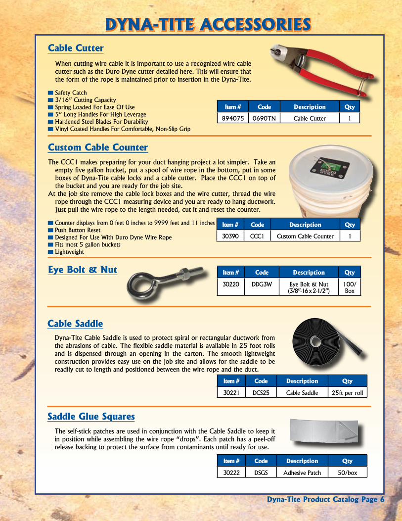
tABLE OF CONtENtS
Benefits 1
Applications 2
Cable Locks 3
installation instructions 4
Accessories 5-6
Starter kit 7
Recommendations & Precautions 7
testing 7
item # Code Description Qty
30220 DDg3W Eye Bolt & nut (3/8’’-16 x 2-1/2’’)
100/Box
item # Code Description Qty
894075 0690Tn Cable Cutter 1
Cable Cutter When cutting wire cable it is important to use a recognized wire cable
cutter such as the Duro Dyne cutter detailed here. This will ensure that the form of the rope is maintained prior to insertion in the Dyna-Tite.
safety Catch 3/16” Cutting Capacity spring Loaded For Ease of Use 5” Long Handles For High Leverage Hardened steel Blades For Durability Vinyl Coated Handles For Comfortable, non-slip grip
DYNA-titE ACCESSORiESDYNA-titE ACCESSORiES
Custom Cable CounterThe CCC1 makes preparing for your duct hanging project a lot simpler. Take an
empty five gallon bucket, put a spool of wire rope in the bottom, put in some boxes of Dyna-Tite cable locks and a cable cutter. Place the CCC1 on top of the bucket and you are ready for the job site.
At the job site remove the cable lock boxes and the wire cutter, thread the wire rope through the CCC1 measuring device and you are ready to hang ductwork. Just pull the wire rope to the length needed, cut it and reset the counter.
Counter displays from 0 feet 0 inches to 9999 feet and 11 inches Push Button reset Designed For Use With Duro Dyne Wire rope Fits most 5 gallon buckets Lightweight
item # Code Description Qty
30390 CCC1 Custom Cable Counter 1
Eye Bolt & Nut
Dyna-tite Product Catalog Page 6
DYNA-titE SYStEM BENEFitS Its time saving qualities have been shown to re-
duce installation by up to 6 times compared to traditional threaded rod.
It provides a fast and strong solution to the task of hanging Mechanical and HVAC
systems.
It allows the installer to position the hangers vertically or at an angle to the suspended object.
Dyna-Tite system is lightweight and easy to carry, and combines these qualities with the inher-ent strength of high tensile wire rope.
Its light weight improves safety on the job. Carry-ing the product on the job site is easy and, in aerial situations reduces accident risk caused by falling materials.
Dyna-tite Product Catalog Page 1
Cable Saddle Dyna-Tite Cable saddle is used to protect spiral or rectangular ductwork from
the abrasions of cable. The flexible saddle material is available in 25 foot rolls and is dispensed through an opening in the carton. The smooth lightweight construction provides easy use on the job site and allows for the saddle to be readily cut to length and positioned between the wire rope and the duct.
item # Code Description Qty
30221 DCs25 Cable saddle 25ft per roll
Saddle Glue Squares The self-stick patches are used in conjunction with the Cable saddle to keep it
in position while assembling the wire rope “drops”. Each patch has a peel-off release backing to protect the surface from contaminants until ready for use.
item # Code Description Qty
30222 Dsgs Adhesive Patch 50/box

DYNE™
© 2009 Duro Dyne Corp.Printed in USA 1/2009
BD030405
®Duro Dyne East Division, Bay Shore, NY 631-249-9000 Fax: 631-249-8346Duro Dyne Midwest Division, Fairfield, OH 513-870-6000 Fax: 513-870-6005Duro Dyne West Division, Santa Fe Springs, CA 562-926-1774 Fax: 562-926-5778Duro Dyne Canada, Lachine, Quebec, Canada 514-422-9760 Fax: 514-636-0328
www.durodyne.com E-mail: [email protected]
RECOMMENDAtiONS & PRECAUtiONSRECOMMENDAtiONS & PRECAUtiONS
tEStiNGtEStiNG All Dyna-Tites have been independently tested to five times their allowable working load by
one or more of the following independent laboratories:
RADCO inc, Long Beach CA SMACNA testing and Research institute New York testing Laboratories Underwriters Laboratories
All Dyna-Tites have been tested to UL 1598 and are listed under File# E246601.
LISTEDLuminaire Fitting14HE
Dyna-tite Product Catalog Page 7
As a matter of sound engineering practice, the Dyna-Tite assembly must be located no closer than 12 inches to the suspension point. In the case of round duct, where the wire rope encircles the duct, the Dyna-Tite must be located the distance of one diameter from the duct wall. Adherence to these minimum clearances will distribute the load the most efficiently among all duct hanging components.
tO ENSURE HANGiNG SYStEM iNtEGRitY AND SAFEtY: Use only Duro Dyne wire rope. tO FACiLitAtE HEiGHt ADjUStMENt: Install the object low and adjust it upwards to the desired level.
DO NOt ExCEED tHE WORkiNG LOAD LiMit (WLL) OF tHE PRODUCt: Each product is load rated and incorporates a minimum safety factor of 5:1. This WLL takes into account the specification criteria of the Dyna-Tite Cable Lock and the wire rope.
DO NOt USE ON COAtED WiRE ROPE: It is important to maintain the metal to metal contact between the lock-ing wedges in the Dyna-Tite and the wire rope.
DO NOt APPLY PAiNt OR OtHER COAtiNG: to any part of the assembly as these may impair the free move-ment of the locking wedges inside the Dyna-Tite Cable Lock.
DO NOt APPLY LUBRiCANt: to any part of the assembly as this will alter the surface nature of the wire rope and attract dirt and debris.
DO NOt USE FOR LiFtiNG: (UnDEr Hook sLIngs) This product is designed for static load applications only.
kEEP tHE PRODUCt CLEAN AND FREE FROM DiRt: Any dirt should be removed from the product prior to assembly.
iNSPECt PERiODiCALLY: Upon inspection, discard and replace if worn, distorted, or damaged.
REMOvE DAMAGED WiRE ENDS: Using a designated pair of wire rope cutters prior to inserting into the Dyna-Tite Cable Lock.
DYNA-titE StARtER kitDYNA-titE StARtER kitThe starter kit has everything you need to get started. iNCLUDES: 1 Roll of 3/32’’ Cable 100 CL12 Cable Locks 1 Custom Cable Counter Lid and Bucket 1 Cable Cutter