Embed Size (px)
Citation preview
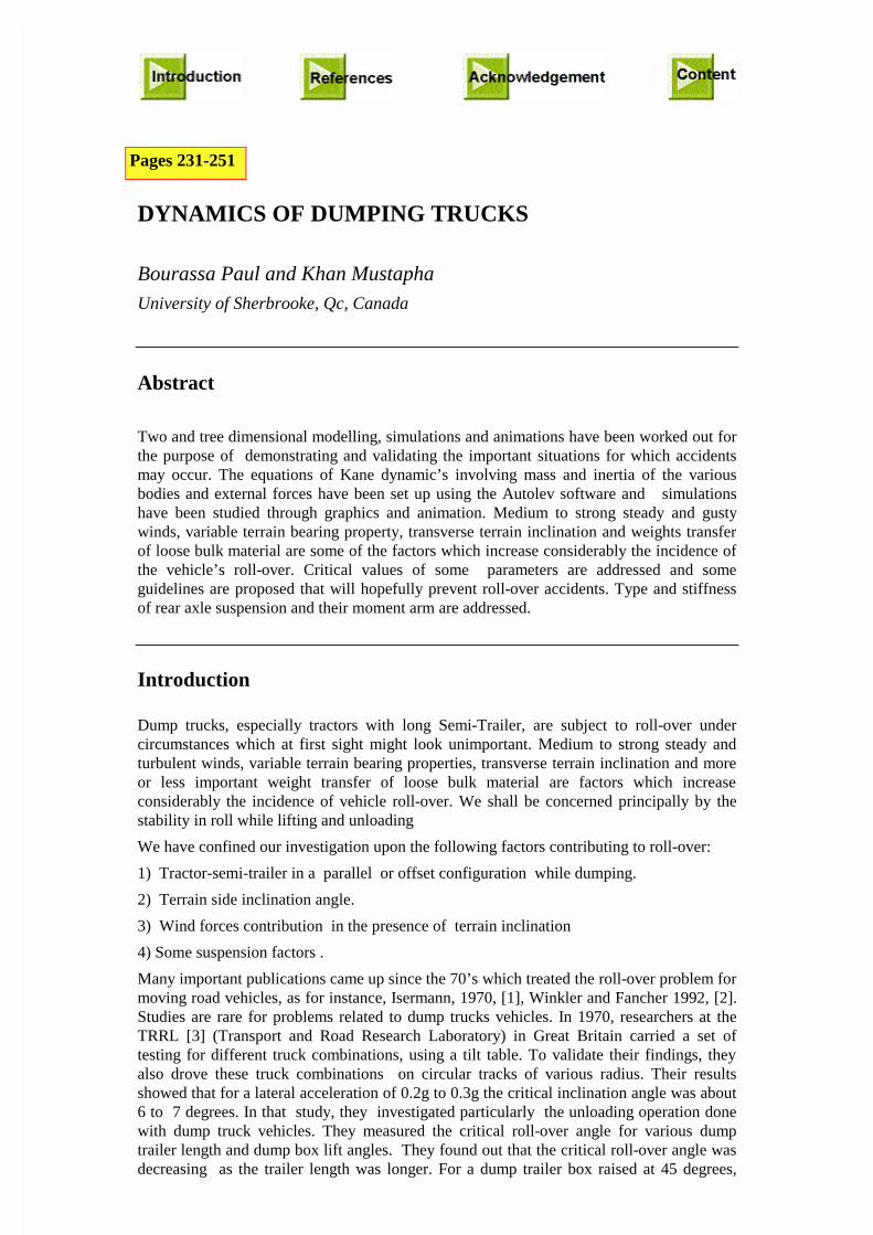
DYNAMICS OF DUMPING TRUCKS
Bourassa Paul and Khan Mustapha
University of Sherbrooke, Qc, Canada
Abstract
Two and tree dimensional modelling, simulations and animations have been worked out forthe purpose of demonstrating and validating the important situations for which accidentsmay occur. The equations of Kane dynamic’s involving mass and inertia of the variousbodies and external forces have been set up using the Autolev software and simulationshave been studied through graphics and animation. Medium to strong steady and gustywinds, variable terrain bearing property, transverse terrain inclination and weights transferof loose bulk material are some of the factors which increase considerably the incidence ofthe vehicle’s roll-over. Critical values of some parameters are addressed and someguidelines are proposed that will hopefully prevent roll-over accidents. Type and stiffnessof rear axle suspension and their moment arm are addressed.
Introduction
Dump trucks, especially tractors with long Semi-Trailer, are subject to roll-over undercircumstances which at first sight might look unimportant. Medium to strong steady andturbulent winds, variable terrain bearing properties, transverse terrain inclination and moreor less important weight transfer of loose bulk material are factors which increaseconsiderably the incidence of vehicle roll-over. We shall be concerned principally by thestability in roll while lifting and unloading
We have confined our investigation upon the following factors contributing to roll-over:
1) Tractor-semi-trailer in a parallel or offset configuration while dumping.
2) Terrain side inclination angle.
3) Wind forces contribution in the presence of terrain inclination
4) Some suspension factors .
Many important publications came up since the 70’s which treated the roll-over problem formoving road vehicles, as for instance, Isermann, 1970, [1], Winkler and Fancher 1992, [2].Studies are rare for problems related to dump trucks vehicles. In 1970, researchers at theTRRL [3] (Transport and Road Research Laboratory) in Great Britain carried a set oftesting for different truck combinations, using a tilt table. To validate their findings, theyalso drove these truck combinations on circular tracks of various radius. Their resultsshowed that for a lateral acceleration of 0.2g to 0.3g the critical inclination angle was about6 to 7 degrees. In that study, they investigated particularly the unloading operation donewith dump truck vehicles. They measured the critical roll-over angle for various dumptrailer length and dump box lift angles. They found out that the critical roll-over angle wasdecreasing as the trailer length was longer. For a dump trailer box raised at 45 degrees,
Pages 231-251
critical roll-over angle as small as 4.3 degrees were observed. A summary of their resultsappears in Table 1.1.
Table 1 Summary of the experimental results of the TRRL study.
Trailer length m. Side angle (box at 0 deg ) Side angle (box at 45 deg)
6.1 13.4 deg 6.2 deg
9.1 11.2 5.2
12.2 9.5 4.3
Novak et al. [3] carried simulations with different unloading situations. Different forwardvelocities were considered during unloading with varying lift angles of the dump box,various terrain conditions as well as different unloading modes. The modes refer here, tothe location and portion of a the stuck carried load when the box is raised to its maximum.The authors reported the following important factors related to roll-overs such as:
1) Terrain unevenness, terrain inclination angle, the presence of holes, bumps, soft-ground,etc.
2) Load: badly distributed load either in a lateral or longitudinal direction. Possible stuckload inside the box.
The accident report of the Committee for Health and Work Security in Quebec lists the typedump vehicles involved in roll-over accidents. Most of them are of the long semi-trailertype. The carried load is either earth or gravel, crushed stone and other high static frictioncoefficient materials.
The present paper is the outcome of a recent research study reported in [5], in a report(in French) , to the IRSST and to the ASTE. A more extended set of results is presentedthere with detailed discussions and conclusions going beyond this presentation.
Modelling
In the present study, a 40 feet semi-trailer, the maximum length allowed in the province ofQuebec, is considered. The load consists of bulk material with a large friction angle. Threetypes of unloading are dealt with; uniform dumping over the whole width of the box,asymmetrical unloading, partial and full stuck bulk load. Steady wind at various velocitiesand orientation with respect to the trailer has been introduced into the model. The effect ofgusty wind is discussed later at the end of the paper.
The dynamic equations of motion and a Fortran code were obtained, using theAutolev code, version 2, for rigid bodies. A set of fifty and more commands areavailable in Autolev 2 and permit the description of a 3 dimensional dynamic modelwith masses, mass moment of inertia, linear and angular velocities andaccelerations, gravity forces, internal and external forces, such as damping andspring forces found in tyres and suspension elements. After compiling and setting upinput files with parameters values and initial conditions, the execution yields fileswhich are used for graphics and animation. Animation in two-dimensional space,were produced and were found very useful in the development stage. A listing of theAutolev commands used to generate a two dimensional simulation program is givenin the appendix.
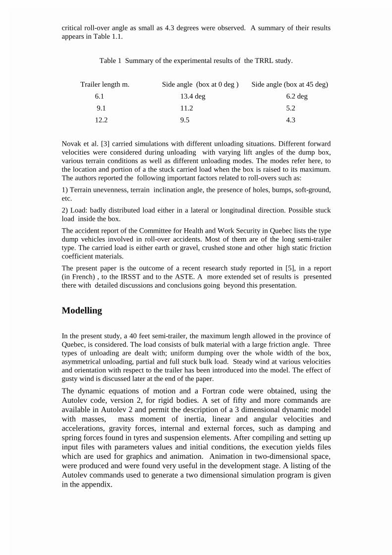
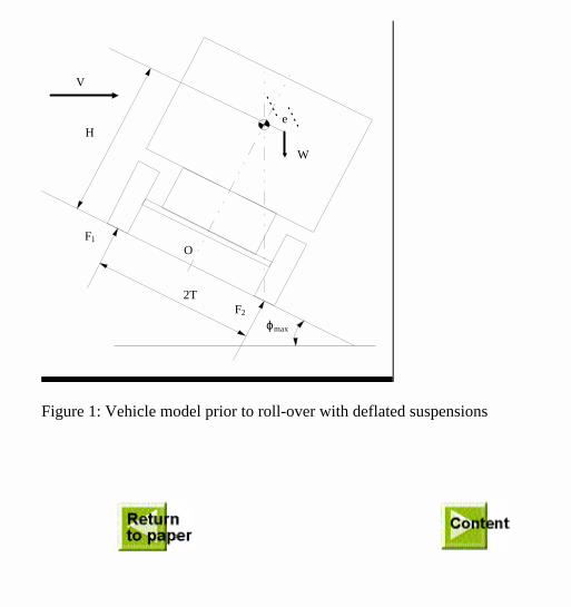
Model with pneumatic but deflated suspensions. During the unloading of bulk materialfrom a dump trailer with deflated pneumatic suspensions, the dump box rests on the frameand the vehicle behaves as a rigid body (Fig 1). The only parameters influencing itsbehaviour are the terrain inclination , the wind direction and velocity and the position of itscentre of gravity, bulk load included.
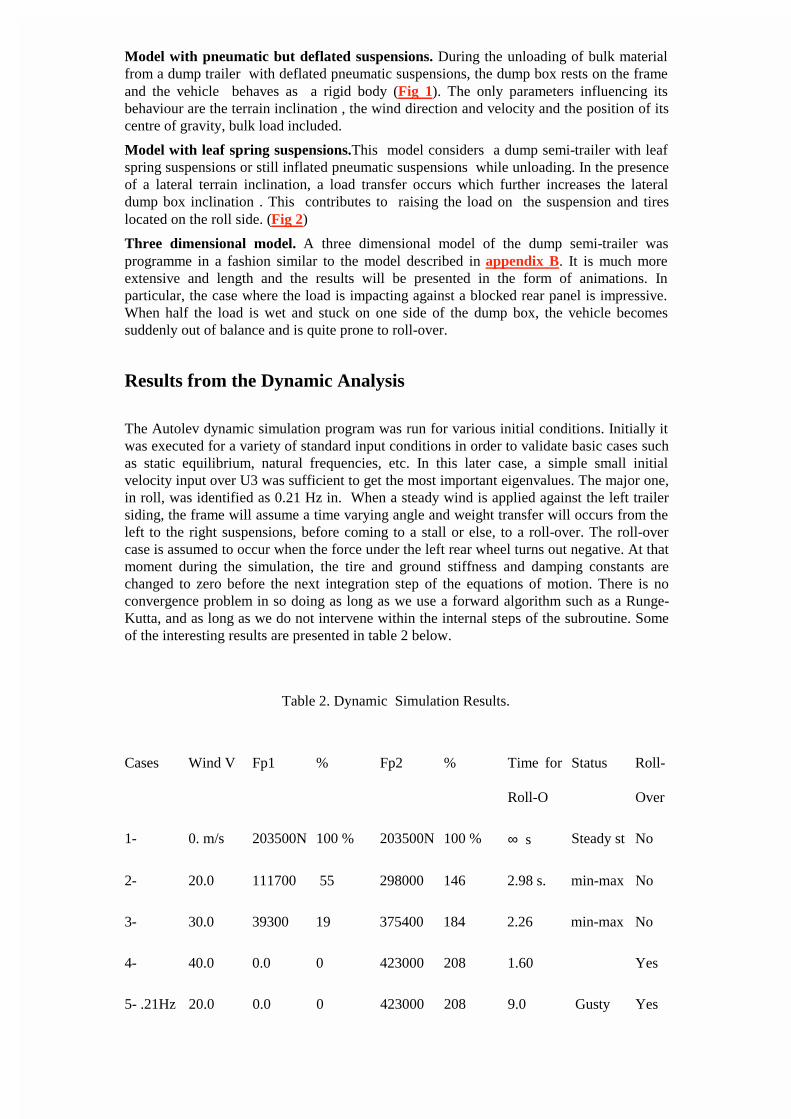
Model with leaf spring suspensions.This model considers a dump semi-trailer with leafspring suspensions or still inflated pneumatic suspensions while unloading. In the presenceof a lateral terrain inclination, a load transfer occurs which further increases the lateraldump box inclination . This contributes to raising the load on the suspension and tireslocated on the roll side. (Fig 2)
Three dimensional model. A three dimensional model of the dump semi-trailer wasprogramme in a fashion similar to the model described in appendix B. It is much moreextensive and length and the results will be presented in the form of animations. Inparticular, the case where the load is impacting against a blocked rear panel is impressive.When half the load is wet and stuck on one side of the dump box, the vehicle becomessuddenly out of balance and is quite prone to roll-over.
Results from the Dynamic Analysis
The Autolev dynamic simulation program was run for various initial conditions. Initially itwas executed for a variety of standard input conditions in order to validate basic cases suchas static equilibrium, natural frequencies, etc. In this later case, a simple small initialvelocity input over U3 was sufficient to get the most important eigenvalues. The major one,in roll, was identified as 0.21 Hz in. When a steady wind is applied against the left trailersiding, the frame will assume a time varying angle and weight transfer will occurs from theleft to the right suspensions, before coming to a stall or else, to a roll-over. The roll-overcase is assumed to occur when the force under the left rear wheel turns out negative. At thatmoment during the simulation, the tire and ground stiffness and damping constants arechanged to zero before the next integration step of the equations of motion. There is noconvergence problem in so doing as long as we use a forward algorithm such as a Runge-Kutta, and as long as we do not intervene within the internal steps of the subroutine. Someof the interesting results are presented in table 2 below.
Table 2. Dynamic Simulation Results.
Cases Wind V Fp1 % Fp2 % Time for
Roll-O
Status Roll-
Over
1- 0. m/s 203500N 100 % 203500N 100 % ∞ s Steady st No
2- 20.0 111700 55 298000 146 2.98 s. min-max No
3- 30.0 39300 19 375400 184 2.26 min-max No
4- 40.0 0.0 0 423000 208 1.60 Yes
5- .21Hz 20.0 0.0 0 423000 208 9.0 Gusty Yes
Case 1 is a simple steady case. When deflexions are properly specified at time zero, there isno motion from step to step integration. Case 2 ,3 and 4 are concerned with steady windforces against the dump box side. Roll-Over occurs at 1.6 s for case 4. For case 2 and 3,some oscillations take place, since the steady wind act as a step force at time zero. What isreported here is the minimum and the maximum load under left and right wheel and theirpercentage with respect to the steady case 1 and the time at which this occurs. Case 5 is agusty wind of average amplitude equal to 20 m/s assumed to be cyclic with a frequency of0.21 hz, the principal natural frequency of the dump box in roll. The roll-over does happenhere after approximately 2 cycles. It is noteworthy to say that the problem is non-linearsince large amplitudes occurs around the roll-over instant.
Gusty winds, oscillating between a minimum of zero wind and a maximum velocity, hasbeen modelled and its effect represented by a offset sinusoidal force. Gusty winds are quiteefficient in producing roll-over when their gust frequency approaches the trailer roll naturalfrequency. Their effect may be compared to the tip-over of car and vans when beingpushed sideways in phase with the rolling mode amplitude.
Other cases are presented here when the dump centre of mass is displaced laterally andwhen the right ground and tire stiffness k2 is reduced, following for example a suddenterrain collapse. The ensuing angular momentum is likely to give the vehicle an importantroll motion.
The following table 3 indicates that the time for roll-over is becoming shorter as one mightexpect. For cases 3 and 4, some special treatment will have to be done to the program sincethe roll-over initially taking place on the right side is reversed after the change in stiffnessk1 in the integration routine.
Table 3. Dynamic Simulations Results for payload off-centre and reduced ground stiffness.
Cases K2 L3 offset F1 F2 Time R-O Remark
1 50% 0 73000
319000
132000
315000
Oscillate No
roll-over
2 50% 0.1 0 148000 1.95s Roll-over
3 50% 0.25 0 222000 1.15s “
4 50% 0.5 0 335000 1.10s “
Results from a steady state analysis.
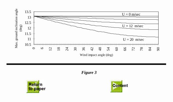
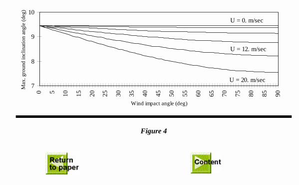
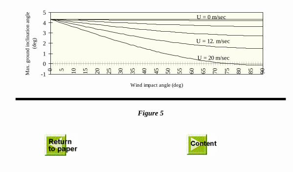
Simulations has been carried out for the two suspension models described above. The windspeed ranged from 0 m/s to 20m/s (72 km/h) with an incidence angle ranging from 0° to90°. The trailer was either in line with or at 90° to its tractor. Linearised equations for staticequilibrium as obtained from appendix A are utilised in this case. The results, giving themaximum permitted sideways terrain angle as a function of wind incidence angle and windvelocity, are shown on the Figures 3 to 6.
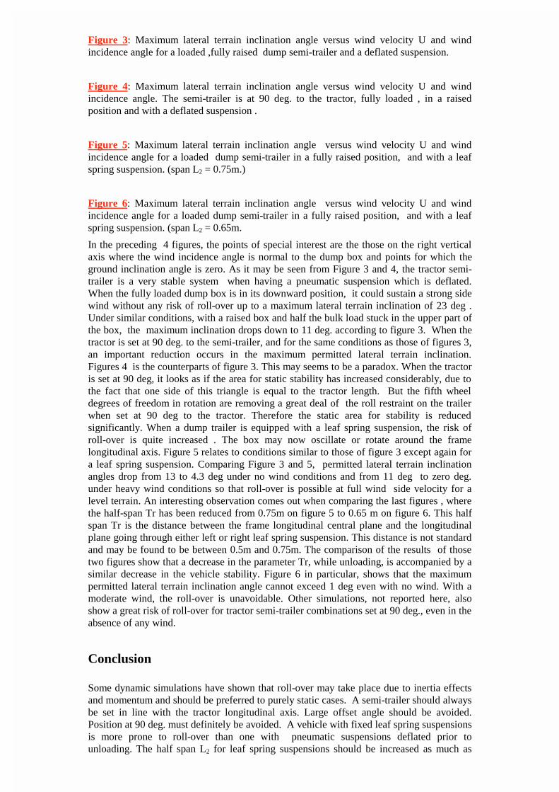
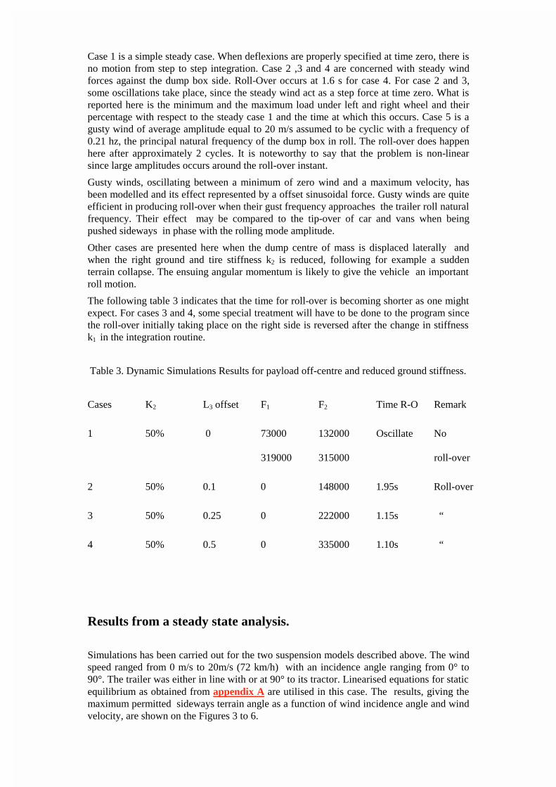
Figure 3: Maximum lateral terrain inclination angle versus wind velocity U and windincidence angle for a loaded ,fully raised dump semi-trailer and a deflated suspension.
Figure 4: Maximum lateral terrain inclination angle versus wind velocity U and windincidence angle. The semi-trailer is at 90 deg. to the tractor, fully loaded , in a raisedposition and with a deflated suspension .
Figure 5: Maximum lateral terrain inclination angle versus wind velocity U and windincidence angle for a loaded dump semi-trailer in a fully raised position, and with a leafspring suspension. (span L2 = 0.75m.)
Figure 6: Maximum lateral terrain inclination angle versus wind velocity U and windincidence angle for a loaded dump semi-trailer in a fully raised position, and with a leafspring suspension. (span L2 = 0.65m.
In the preceding 4 figures, the points of special interest are the those on the right verticalaxis where the wind incidence angle is normal to the dump box and points for which theground inclination angle is zero. As it may be seen from Figure 3 and 4, the tractor semi-trailer is a very stable system when having a pneumatic suspension which is deflated.When the fully loaded dump box is in its downward position, it could sustain a strong sidewind without any risk of roll-over up to a maximum lateral terrain inclination of 23 deg .Under similar conditions, with a raised box and half the bulk load stuck in the upper part ofthe box, the maximum inclination drops down to 11 deg. according to figure 3. When thetractor is set at 90 deg. to the semi-trailer, and for the same conditions as those of figures 3,an important reduction occurs in the maximum permitted lateral terrain inclination.Figures 4 is the counterparts of figure 3. This may seems to be a paradox. When the tractoris set at 90 deg, it looks as if the area for static stability has increased considerably, due tothe fact that one side of this triangle is equal to the tractor length. But the fifth wheeldegrees of freedom in rotation are removing a great deal of the roll restraint on the trailerwhen set at 90 deg to the tractor. Therefore the static area for stability is reducedsignificantly. When a dump trailer is equipped with a leaf spring suspension, the risk ofroll-over is quite increased . The box may now oscillate or rotate around the framelongitudinal axis. Figure 5 relates to conditions similar to those of figure 3 except again fora leaf spring suspension. Comparing Figure 3 and 5, permitted lateral terrain inclinationangles drop from 13 to 4.3 deg under no wind conditions and from 11 deg to zero deg.under heavy wind conditions so that roll-over is possible at full wind side velocity for alevel terrain. An interesting observation comes out when comparing the last figures , wherethe half-span Tr has been reduced from 0.75m on figure 5 to 0.65 m on figure 6. This halfspan Tr is the distance between the frame longitudinal central plane and the longitudinalplane going through either left or right leaf spring suspension. This distance is not standardand may be found to be between 0.5m and 0.75m. The comparison of the results of thosetwo figures show that a decrease in the parameter Tr, while unloading, is accompanied by asimilar decrease in the vehicle stability. Figure 6 in particular, shows that the maximumpermitted lateral terrain inclination angle cannot exceed 1 deg even with no wind. With amoderate wind, the roll-over is unavoidable. Other simulations, not reported here, alsoshow a great risk of roll-over for tractor semi-trailer combinations set at 90 deg., even in theabsence of any wind.
Conclusion
Some dynamic simulations have shown that roll-over may take place due to inertia effectsand momentum and should be preferred to purely static cases. A semi-trailer should alwaysbe set in line with the tractor longitudinal axis. Large offset angle should be avoided.Position at 90 deg. must definitely be avoided. A vehicle with fixed leaf spring suspensionsis more prone to roll-over than one with pneumatic suspensions deflated prior tounloading. The half span L2 for leaf spring suspensions should be increased as much as
possible when designing dumping trailers. Minimal width for such span should be imposedfor bulk dumping vehicles. Pneumatic suspensions are to be preferred as long as theattendant deflates them prior to lifting its dump box. Often, this is not the case. Dumpingshould not proceed when carrying bulk material with a high friction coefficient, speciallywhen this material has been soaked with rain, and other conditions prevail such as uneventerrain, leaf spring suspensions, presence of steady or gusty winds. Operators should inspectthe loaded material for evenness and dry conditions before raising their box.

Acknowledgement
The authors want to acknowledge the I.R.S.S.T., ASTE and NSERC for their financialsupport.
References
[1] Isermann H., Overturning Limits of Articulated Vehicles with Solid and LiquidLoad, Motor Industry Research Association, Translation No. 58/70, 1970
[2] Winkler C. B., Fancher P. S., Scenarios for Regulation of Commercial VehicleStability In The US, Presented at the Fourth International Heavy Vehicle Seminar,Auckland, New Zealand, March 3-5, 1992.
[3] Novak A. J., Nowak J. W., Larson C. S., Computer Simulation of Semi-TrailerHaul Truck Roll-Over Dynamics, SAE Technical Paper Series No. 901623, 1990(Published also in Proceedings of the International Off-Highway & PowerplantCongress and Exposition, Milwaukee, Wisconsin, September 10-13, 1990).
[4] Kemp R. N., Eng C., Chinn B. P., Brock G., Articulated Vehicle Roll Stability:Methods of Assessment and Effects of Vehicles Characteristics, Transport andRoad Research Laboratory, TRRL Laboratory Report 788, Crowthorne, Berkshire,England, 1978.
[5] Khan M., Bourassa P., Projet de recherches sur la stabilité des camions etremorques à bennes basculantes. IRSST; Montréal, Qué, Canada.
[6] Bourassa P.,Khan M.,Tartre A. “Roll-Over of Dump Trucks while Dumping.Proceedings International Large Truck Safety Symposium, University ofTennessee, Knoxville, Tennessee, Oct 1997 pp 459-469
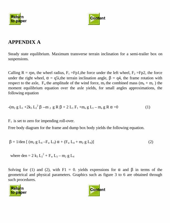
APPENDIX A
Steady state equilibrium. Maximum transverse terrain inclination for a semi-trailer box onsuspensions.
Calling R = rpn, the wheel radius, F1 =Fp1,the force under the left wheel, F2 =Fp2, the forceunder the right wheel, α = q5i,the terrain inclination angle, β = q4, the frame rotation withrespect to the axle, Fw the amplitude of the wind force, m2 the combined mass (mb + mc ) themoment equilibrium equation over the axle yields, for small angles approximations, thefollowing equation
-(m2 g L1 +2k3 L22 β --m 2 g R β + 2 L1 F1 +ma g L1 – ma g R α =0 (1)
F1 is set to zero for impending roll-over.
Free body diagram for the frame and dump box body yields the following equation.
β = 1/den [ (m2 g L4 –Fw L3) α + (Fw L4 + m2 g L4)] (2)
where den = 2 k3 L22 + Fw L3 – m2 g L4
Solving for (1) and (2), with F1 = 0. yields expressions for α and β in terms of thegeometrical and physical parameters. Graphics such as figure 3 to 6 are obtained throughsuch procedures.

Appendix BAutolev Commands for the Two dimensional Roll Over Simulation Program
All angles are in radians.
DOF(4)
FRAMES(A,B,C)
mass(a,ma,b,mb,c,mc)
PRINCIPAL(A,B,C)
!R7 is a point where wind resultant force is applied.
POINTS(O,R1,R2,R3,R4,R5,R6,r7,r8,r11,r22)
!R11 and R22 are road contact points below R1 and R2 at radius RPN
!Ls3 is the initial suspension length from R3 to R5 and from R4 to R6
MASSLESS(O,R1,R2,R3,R4,R5,R6,r7,r8,r11,r22)
CONST(RHO,CD,S,uv,L1,L2,L3,L4,L5,L6)
CONST(G,K1,K2,K3,K4,ls3,AM1,AM2,AM3,AM4,ab,rpn,f,q5i,q6i,kh)
specified(q5,q6)
!q5i is the initial transverse road angle as read in the input file
!q6i is the angle at which the box is beeing raised.(rad)
q5=q5i
q6=q6i
SIMPROT(N,A,3,(Q3-Q5))
SIMPROT(A,B,3,Q4)
DIRCOS(N,B)
SIMPROT(B,C,1,Q6)
DIRCOS(N,C)
DIRCOS(A,C)
WAN=U3*A3
WBA=U4*B3
WBN=ADD(WAN,WBA)
EXPRESS(WBN,N)
WCN=ADD(WAN,WBA)
EXPRESS(WCN,C)
Q1'=U1
Q2'=U2
Q3'=U3
Q4'=U4
ALFAN=DERIV(WAN,T,N)
ALFBN=DERIV(WBN,T,N)

ALFCN=DERIV(WCN,T,N)
!Point O is a fixed reference origin in the Newtonian Frame.
PON=0*N1+0*N2
VON=0.0*N1+0.0*N2
POASTAR=Q1*N1+Q2*N2
VASTARN=U1*N1+U2*N2
!R1 and R2 are axle points where equivalent tires loads are applied.
PASTARR1=-L1*A1
PASTARR2=L1*A1
!R5,R6 are box application points for equivalent suspension forces.
PASTARR3=-L2*A1
PASTARR4=L2*A1
PR1R11=-RPN*A2
PR2R22=-RPN*A2
!velocities commands
V2PTS(N,A,ASTAR,R1)
V2PTS(N,A,ASTAR,R2)
V2PTS(N,A,ASTAR,R3)
V2PTS(N,A,ASTAR,R4)
V2PTS(N,A,ASTAR,R22)
V2PTS(N,A,ASTAR,R11)
!Bstar is Frame center of mass assumed to be articulated around A*
PASTARBSTAR=AB*B2
V2PTS(N,B,ASTAR,BSTAR)
! location of R5 and R6 on the chassis.
PBSTARR5=-L2*B1
PBSTARR6=L2*B1
!Cstar or C* is the box and payload center of mass.
PBSTARCSTAR=L3*B1+L4*B2
!R7 and R8 are points on the box sides for external forces (wind..)
PBSTARR7=-L5*C1+L6*C2
PBSTARR8=L5*C1+L6*C2
!vectors from fixed point O are formed for later animations.
POBSTAR=ADD(POASTAR,PASTARBSTAR)
POCSTAR=ADD(POBSTAR,PBSTARCSTAR)
EXPRESS(POCSTAR,N)
POR1=ADD(POASTAR,PASTARR1)
EXPRESS(POR1,N)
POR2=ADD(POASTAR,PASTARR2)
EXPRESS(POR2,N)
POR3=ADD(POASTAR,PASTARR3)
EXPRESS(POR3,N)

POR4=ADD(POASTAR,PASTARR4)
EXPRESS(POR4,N)
POR5=ADD(POBSTAR,PBSTARR5)
EXPRESS(POR5,N)
POR6=ADD(POBSTAR,PBSTARR6)
EXPRESS(POR6,N)
POR7=ADD(POBSTAR,PBSTARR7)
EXPRESS(POR7,N)
POR8=ADD(POBSTAR,PBSTARR8)
POR11=ADD(POR1,PR1R11)
POR22=ADD(POR2,PR2R22)
!projections of the previous vectors are needed for the animations.
XR11=DOT(POR11,N1)
YR11=DOT(POR11,N2)
XR22=DOT(POR22,N1)
YR22=DOT(POR22,N2)
XR1=DOT(POR1,N1)
YR1=DOT(POR1,N2)
XR2=DOT(POR2,N1)
YR2=DOT(POR2,N2)
XASTAR=DOT(POASTAR,N1)
YASTAR=DOT(POASTAR,N2)
XR3=DOT(POR3,N1)
YR3=DOT(POR3,N2)
XR4=DOT(POR4,N1)
YR4=DOT(POR4,N2)
XBSTAR=DOT(POBSTAR,N1)
YBSTAR=DOT(POBSTAR,N2)
XR5=DOT(POR5,N1)
YR5=DOT(POR5,N2)
XR6=DOT(POR6,N1)
YR6=DOT(POR6,N2)
XR7=DOT(POR7,N1)
YR7=DOT(POR7,N2)
XCSTAR=DOT(POCSTAR,N1)
YCSTAR=DOT(POCSTAR,N2)
XR8=DOT(POR8,N1)
YR8=DOT(POR8,N2)
!following controls yield output files for the specified variables.
CONTROLS(XR11,YR11,XR1,YR1,XR22,YR22,XR2,YR2,XASTAR,YASTAR)
CONTROLS(XR3,YR3,XR4,YR4,XBSTAR,YBSTAR,XR5,YR5,XR6,YR6)
CONTROLS(XR7,YR7,XCSTAR,YCSTAR,XR8,YR8)

!mass centers velocities and accelerations.
V2PTS(N,B,BSTAR,R5)
V2PTS(N,B,BSTAR,R6)
V2PTS(N,B,BSTAR,R7)
V2PTS(N,C,BSTAR,CSTAR)
AASTARN=DERIV(VASTARN,T,N)
ABSTARN=DERIV(VBSTARN,T,N)
ACSTARN=DERIV(VCSTARN,T,N)
!gravity forces on each mass
FORCE(ASTAR)=-G*MA*N2
FORCE(BSTAR)=-G*MB*N2
FORCE(CSTAR)=-G*MC*N2
!wind force on R7
FORCE(R7)=(1/2)*RHO*CD*S*(UV)^2*(1.-SIN(2*PI*F*T))*cos(Q3+Q4-Q5)*b1
! extr1 is the combined tire and ground deflexion under left wheel.
!Roll-over start when extr1 becomes positive.
EXTR1=DOT(POR11,N2)
!extr2 is the opposite deflexion under the right wheel.
EXTR2=DOT(POR22,N2)
!dextr1 is the deformation rate needed for damping forces.
DEXTR1=DOT(VR11N,A2)
DEXTR2=DOT(VR22N,A2)
!ground forces (elasticity and damping )
FORCE(R11)=(-K1*RIGHT(EXTR1)-AM1*RIGHT(DEXTR1))*A2
FORCE(R22)=-KH*Q1*N1+(-K2*RIGHT(EXTR2)-AM2*RIGHT(DEXTR2))*A2
PR3R5=ADD(POR5,-POR3)
!frame suspension deflexion
EXTR3=DOT(PR3R5,A2)
PR4R6=ADD(POR6,-POR4)
EXTR4=DOT(PR4R6,A2)
!suspension rates of deflexion
DEXTR3=DERIV(EXTR3,T)
DEXTR4=DERIV(EXTR4,T)
! output files are requested.
CONTROLS(EXTR1,EXTR2,EXTR3,EXTR4)
!Frame suspension forces
FORCE(R3/R5)=-K3*(RIGHT(EXTR3)-LS3)*A2-AM3*RIGHT(DEXTR3)*A2
FORCE(R4/R6)=-K3*(RIGHT(EXTR4)-LS3)*A2-AM3*RIGHT(DEXTR4)*A2
!forces on wheels
FP1=DOT(FORCE(R11),A2)
FP2=DOT(FORCE(R22),A2)
!forces from the axle to the frame

FP3=DOT(FORCE(R3/R5),A2)
FP4=DOT(FORCE(R4/R6),A2)
!Transverse forces from the wind.
FP5=DOT(FORCE(R7),b1)
!output files for the wind and suspension forces.
CONTROLS(FP1,FP2,FP3,FP4,FP5)
!Command for the generalised forces for the Kane equations.
FR
!Command for the evaluation of the Kane equations inertia forces.
FRSTAR
!Command for the symbolic expressions of the Dynamics Kane equations
KANE
!Command for making a file containing all symbolic evaluations.
RECORD(BEN4,ALL)
!Fortran source code command.
CODE(BEN4,SUBS)
Appendix CList of parameters used in the dynamic program.
1-rh0 = 1.2 Air density kg/m3
2-cd = 2.3 Drag coefficient
3-S = 35.1 Trailer side surface m2
4-uv = 0, 4. - 40.0 Wind velocity m/s
5-L1 = 0.975 Distance from rear axle centre to the wheels centre.m.
6-L2 = 0.65 Distance from the rear axle centre to the suspension centre.m.
7-L3 = 0.0 Off centre side distance of the payload and dump box centre of massm.
8-L4 = 0.914 Height of mass centre above the frame centre of mass B* m.
9-L5 = 1.19 Box half width m.
10-L6 = .915 Height at which the wind resultant will act m.
11-G = 9.81 Earth gravity constant
12-K1 = 2 E06-8E06. Tire and ground stiffness for the left rear wheel N/m.
13-K2 = 2 E06-2E06 Tire and ground stiffness for the right rear wheel N/m.
14-k3 = “ Rear leaf spring suspension stiffness either side N/m.
15-k4 = 0. “ Standby spring stiffness N/m.
16-Ls3 = 0.87 Initial spring length for k3 and k4 m.
17-am1 = 0.0 - Rear left tire and ground damping constant
18-am2 = 0. Rear and right tire and ground damping constant.
19-am3 = 0. Rear suspension damping constant over R5 and R6.
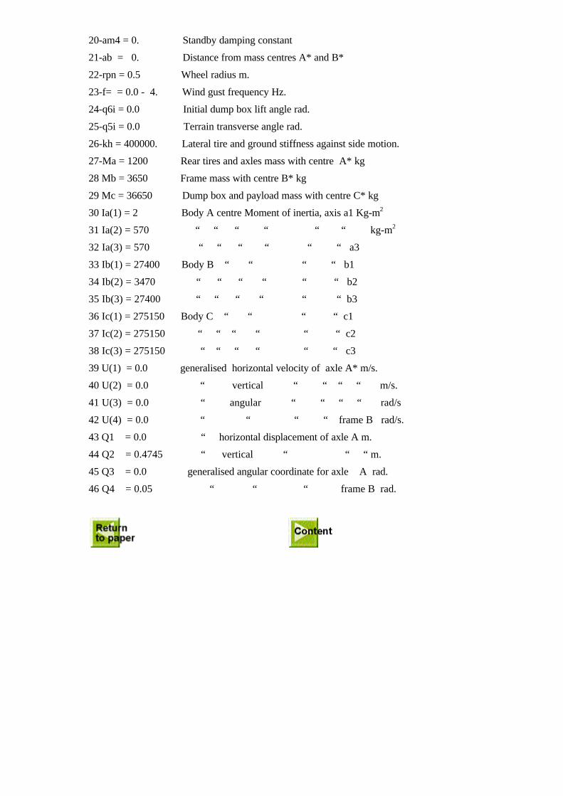
20-am4 = 0. Standby damping constant
21-ab = 0. Distance from mass centres A* and B*
22-rpn = 0.5 Wheel radius m.
23-f= = 0.0 - 4. Wind gust frequency Hz.
24-q6i = 0.0 Initial dump box lift angle rad.
25-q5i = 0.0 Terrain transverse angle rad.
26-kh = 400000. Lateral tire and ground stiffness against side motion.
27-Ma = 1200 Rear tires and axles mass with centre A* kg
28 Mb = 3650 Frame mass with centre B* kg
29 Mc = 36650 Dump box and payload mass with centre C* kg
30 Ia(1) = 2 Body A centre Moment of inertia, axis a1 Kg-m2
31 Ia(2) = 570 “ “ “ “ “ “ kg-m2
32 Ia(3) = 570 “ “ “ “ “ “ a3
33 Ib(1) = 27400 Body B “ “ “ “ b1
34 Ib(2) = 3470 “ “ “ “ “ “ b2
35 Ib(3) = 27400 “ “ “ “ “ “ b3
36 Ic(1) = 275150 Body C “ “ “ “ c1
37 Ic(2) = 275150 “ “ “ “ “ “ c2
38 Ic(3) = 275150 “ “ “ “ “ “ c3
39 U(1) = 0.0 generalised horizontal velocity of axle A* m/s.
40 U(2) = 0.0 “ vertical “ “ “ “ m/s.
41 U(3) = 0.0 “ angular “ “ “ “ rad/s
42 U(4) = 0.0 “ “ “ “ frame B rad/s.
43 Q1 = 0.0 “ horizontal displacement of axle A m.
44 Q2 = 0.4745 “ vertical “ “ “ m.
45 Q3 = 0.0 generalised angular coordinate for axle A rad.
46 Q4 = 0.05 “ “ “ frame B rad.
H
2T
F1
F2
W
ϕmax
O
e
V
Figure 1: Vehicle model prior to roll-over with deflated suspensions
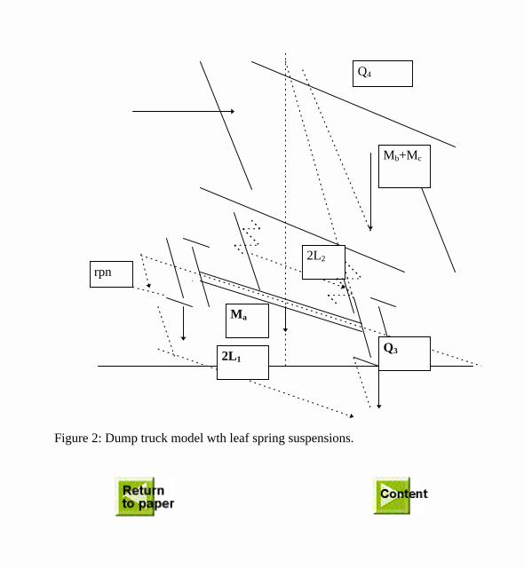
Figure 2: Dump truck model wth leaf spring suspensions.
Q3
Ma
Mb+Mc
Q4
2L2
2L1
rpn
10.5
11
11.5
12
12.5
13
13.5
0 6 12 18 24 30 36 42 48 54 60 66 72 78 84 90
Wind impact angle (deg)
Max
. gro
und
incl
inat
ion
angl
e (d
eg)
U = 0 m/sec
U = 12 m/sec
U = 20 m/sec
Figure 3
7
8
9
10
0 5 10
15
20
25
30
35
40
45
50
55
60
65
70
75
80
85
90
Wind impact angle (deg)
Max
. gro
und
incl
inat
ion
angl
e (d
eg)
U = 0. m/sec
U = 12. m/sec /
U = 20. m/sec
Figure 4
-1
0
1
2
3
4
5
0 5 10
15
20
25
30
35
40
45
50
55
60
65
70
75
80
85
90
Wind impact angle (deg)
Max
. gro
und
incl
inat
ion
angl
e (d
eg)
U = 12. m/sec
U = 20 m/sec
U = 0 m/sec
Figure 5
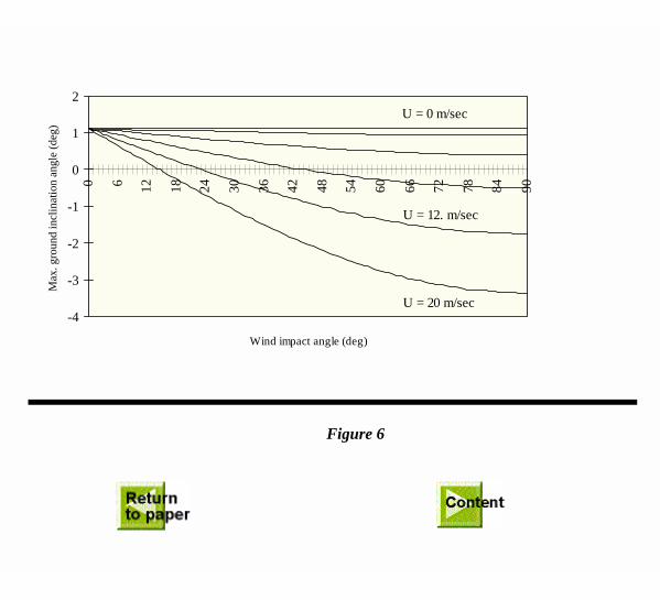
Figure 6
-4
-3
-2
-1
0
1
20 6 12
18
24
30
36
42
48
54
60
66
72
78
84
90
Wind impact angle (deg)
Max
. gro
und
incl
inat
ion
angl
e (d
eg)
U = 12. m/sec
U = 20 m/sec
U = 0 m/sec