Embed Size (px)
Citation preview

Dynamics

Newton's Three Laws of MotionInertial Reference FramesMass vs. WeightForces we studied: weight / gravity normal force tension friction (kinetic and static)Drawing Free Body DiagramsProblem Solving
Things to Remember from Last Year

Newton's Laws of Motion
1. An object maintains its velocity (both speed and direction) unless acted upon by a nonzero net force.
2. Newton’s second law is the relation between acceleration and force.
3. Whenever one object exerts a force on a second object, the second object exerts an equal force in the opposite direction on the first object.
ΣF = ma
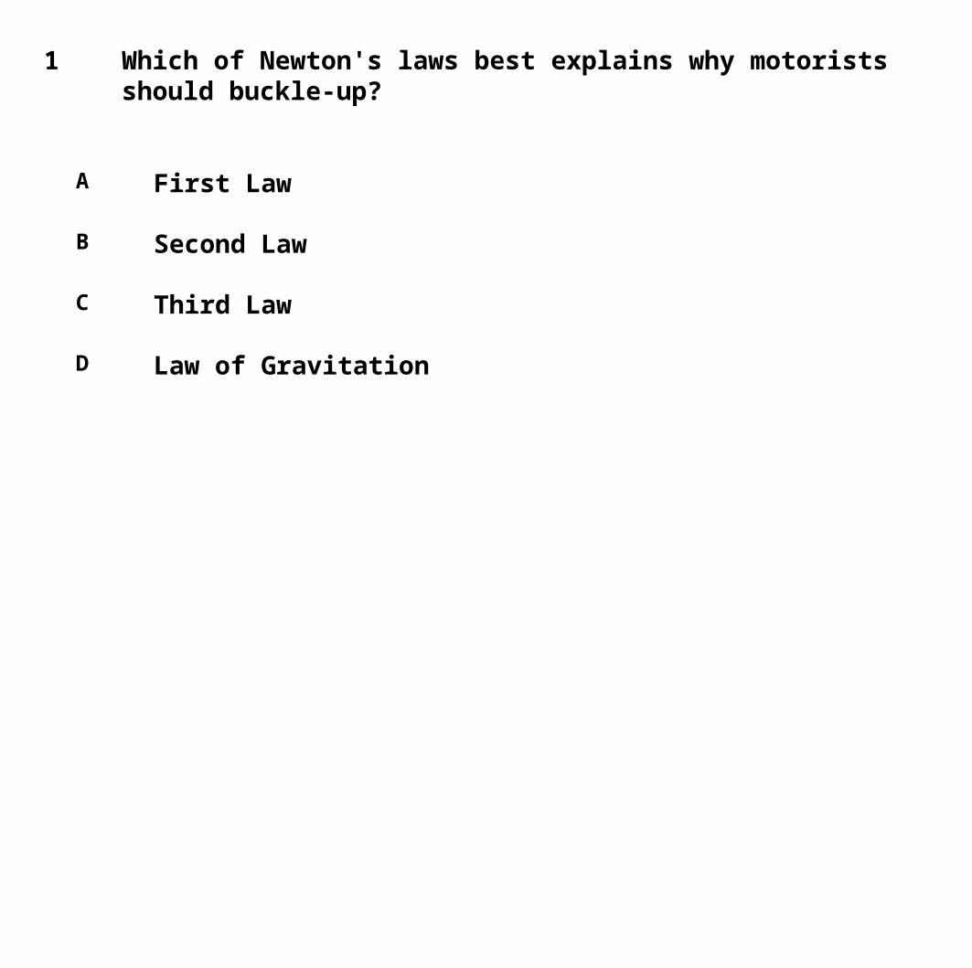
1 Which of Newton's laws best explains why motorists should buckle-up?
A First Law
B Second Law
C Third Law
D Law of Gravitation

2 You are standing in a moving bus, facing forward, and you suddenly fall forward. You can infer from this that the bus's
A velocity decreased.
B velocity increased.
C speed remained the same, but it is turning to the right.
D speed remained the same, but it is turning to the left.

3 You are standing in a moving bus, facing forward, and you suddenly fall forward as the bus comes to an immediate stop. What force caused you to fall forward?
A gravity
B normal force due to your contact with the floor of the bus
C force due to friction between you and the floor of the bus
D There is not a force leading to your fall.

4 When the rocket engines on the spacecraft are suddenly turned off, while traveling in empty space, the starship will
A stop immediately.
B slowly slow down, then stop.
C go faster.
D move with constant speed

5 A net force F accelerates a mass m with an acceleration a. If the same net force is applied to mass 2m, then the acceleration will be
A 4a
B 2a
C a/2
D a/4

6 A net force F acts on a mass m and produces an acceleration a. What acceleration results if a net force 2F acts on mass 4m?
A a/2
B 8a
C 4a
D 2a

7 An object of mass m sits on a flat table. The Earth pulls on this object with force mg, which we will call the action force. What is the reaction force?
A The table pushing up on the object with force mg
B The object pushing down on the table with force mg
C The table pushing down on the floor with force mg
D The object pulling upward on the Earth with force mg

8 A 20-ton truck collides with a 1500-lb car and causes a lot of damage to the car. Since a lot of damage is done on the car
A the force on the truck is greater then the force on the car
B the force on the truck is equal to the force on the car
C the force on the truck is smaller than the force on the car
D the truck did not slow down during the collision

Newton's laws are only valid in inertial reference frames:
An inertial reference frame is one in which Newton’s first law is valid. This excludes rotating and accelerating frames.
Inertial Reference Frames

MASS is the measure of the inertia of an object, the resistance of an object to accelerate.
WEIGHT is the force exerted on that object by gravity. Close to the surface of the Earth, where the gravitational force is nearly constant, the weight is:
Mass is measured in kilograms, weight Newtons.
Mass and Weight
FG = mg

Normal Force and Weight
FN
mg
The Normal Force, FN, is ALWAYS perpendicular to the surface.
Weight, mg, is ALWAYS directed downward.

9 The acceleration due to gravity is lower on the Moon than on Earth. Which of the following is true about the mass and weight of an astronaut on the Moon's surface, compared to Earth?
A Mass is less, weight is same
B Mass is same, weight is less
C Both mass and weight are less
D Both mass and weight are the same

10 A 14 N brick is sitting on a table. What is the normal force supplied by the table?
A 14 N upwards
B 28 N upwards
C 14 N downwards
D 28 N downwards
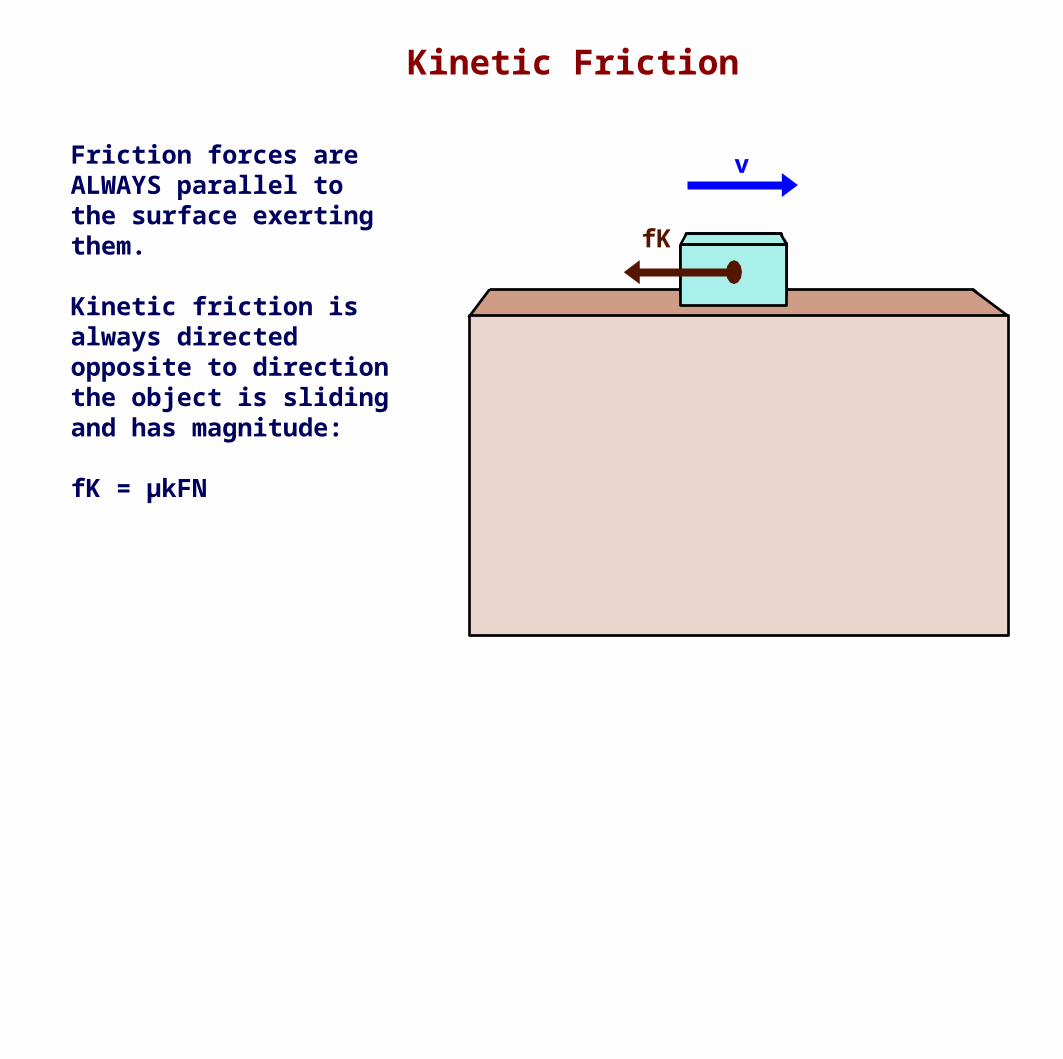
Kinetic Friction
fK
vFriction forces are ALWAYS parallel to the surface exerting them.
Kinetic friction is always directed opposite to direction the object is sliding and has magnitude:
fK = μkFN

11 A 4.0kg brick is sliding on a surface. The coefficient of kinetic friction between the surfaces is 0.25. What it the size of the force of friction?
A 8.0
B 8.8
C 9.0
D 9.8

12 A brick is sliding to the right on a horizontal surface.
What are the directions of the two surface forces: the friction force and the normal force?
A right, down
B right, up
C left, down
D left, up

Static Friction
fS FAPP
Static friction is always equal and opposite the Net Applied Force acting on the object (not including friction).
Its magnitude is:
fS ≤ μSFN

13 A 4.0 kg brick is sitting on a table. The coefficient of static friction between the surfaces is 0.45. What is the largest force that can be applied horizontally to the brick before it begins to slide?
A 16.33
B 17.64
C 17.98
D 18.12

14 A 4.0kg brick is sitting on a table. The coefficient of static friction between the surfaces is 0.45. If a 10 N horizontal force is applied to the brick, what will be the force of friction and will the brick move?
A 16.12, no
B 17.64, no
C 16.12, yes
D 17.64, yes
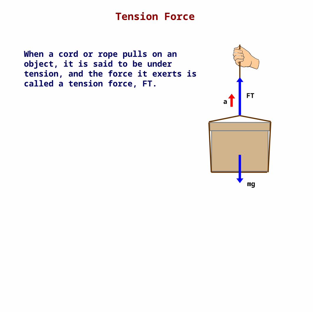
When a cord or rope pulls on an object, it is said to be under tension, and the force it exerts is called a tension force, FT.
Tension Force
FT
mg
a

15 A crane is lifting a 60 kg load at a constant velocity. Determine the tension force in the cable.
A 568 N
B 578 N
C 504 N
D 600 N

16 A system of two blocks is accelerated by an applied force of magnitude F on the frictionless horizontal surface. The tension in the string between the blocks is:
A 6F
B 4F
C 3/5 F
D 1/6 F
E 1/4 F
6 kg 4 kg F

Two Dimensions

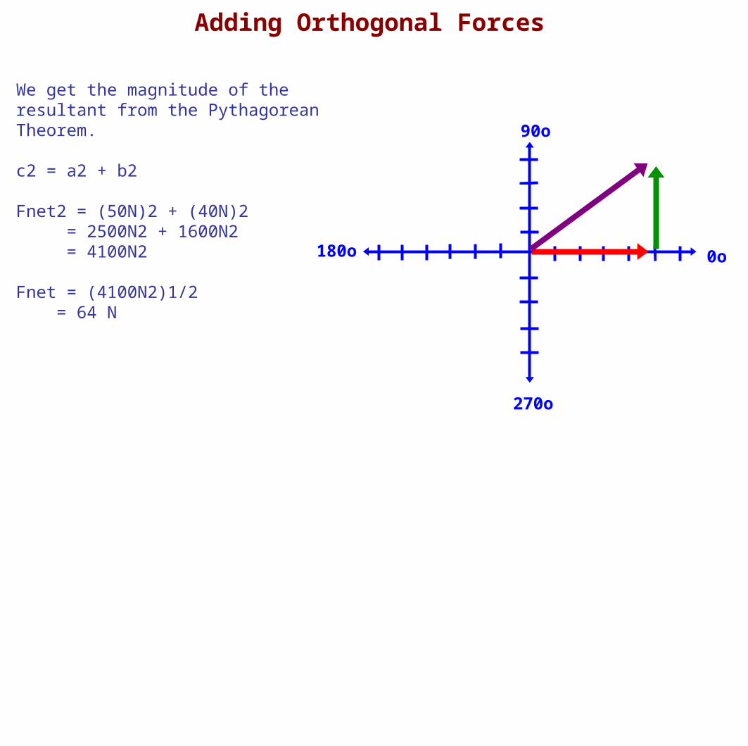
Since forces are vectors, they add as vectors.
The simplest case is if the forces are perpendicular (orthogonal) with another.
Let's add a 50 N force at 0o with a 40 N force at 90o.
Adding Orthogonal Forces

180o
90o
270o
0o
1. Draw the first force vector, 50 N at 0o, beginning at the origin.
Adding Orthogonal Forces

180o
90o
270o
0o
1. Draw the first force vector, 50 N at 0o, beginning at the origin.
2. Draw the second force vector, 40 N at 90o, with its tail at the tip of the first vector.
Adding Orthogonal Forces

180o
90o
270o
0o
1. Draw the first force vector, 50 N at 0o, beginning at the origin.
2. Draw the second force vector, 40 N at 90o, with its tail at the tip of the first vector.
3. Draw Fnet from the tail of the first force to the tip of the last force.
Adding Orthogonal Forces
180o
90o
270o
0o
We get the magnitude of the resultant from the Pythagorean Theorem.
c2 = a2 + b2
Fnet2 = (50N)2 + (40N)2 = 2500N2 + 1600N2 = 4100N2
Fnet = (4100N2)1/2 = 64 N
Adding Orthogonal Forces

180o
90o
270o
0o
Adding Orthogonal Forces
We get the direction of the net Force from the inverse tangent.
tan(θ) = opp / adj
tan(θ) = (40N) / (50N)
tan(θ) = 4/5
tan(θ) = 0.8
θ = tan-1(0.80) = 39o
Fnet = 64 N at 39o

180o
90o
270o
0o
Decomposing Forces into Orthogonal Components
Let's decompose a 120 N force at 34o into its x and y components.
F
θ

180o
90o
270o
0o
Decomposing Forces into Orthogonal Components
We have Fnet, which is the hypotenuse, so let's first find the adjacent side by using
cosθ = adj / hypcosθ = Fx / Fnet
Fx = Fnet cosθ = 120N cos34o = 100 N
F
Fx
θ

180o
90o
270o
0o
Decomposing Forces into Orthogonal Components
Now let's find the opposite side by using
sinθ = adj / hypsinθ = Fy / Fnet
Fy = Fnet sinθ = 120N sin34o = 67 N
Fx
F Fy
θ

Adding non-Orthogonal Forces
Now that we know how to add orthogonal forces.
And we know now to break forces into orthogonal components, so we can make any force into two orthogonal forces.
We combine those two steps to add any number of forces together at any different angles.

Adding non-Orthogonal Forces
Let's add together these three forces:
F1 = 8.0 N at 50oF2 = 6.5 N at 75oF3 = 8.4 N at 30o
First, we will do it graphically, to show the principle for how we will do it analytically.
Then, we will do it analytically, which is easy once you see why it works that way.

180o
90o
270o
0o
Adding non-Orthogonal Forces
F1 = 4.0 N at 50oF2 = 6.5 N at 75oF3 = 8.4 N at 30o
First, here are the vectors all drawn from the origin.

180o
90o
270o
0o
Adding non-Orthogonal Forces
F1 = 4.0 N at 50oF2 = 6.5 N at 75oF3 = 8.4 N at 30o
Now we arrange them tail to tip.
F1
F2
F3
180o
90o
270o
0o
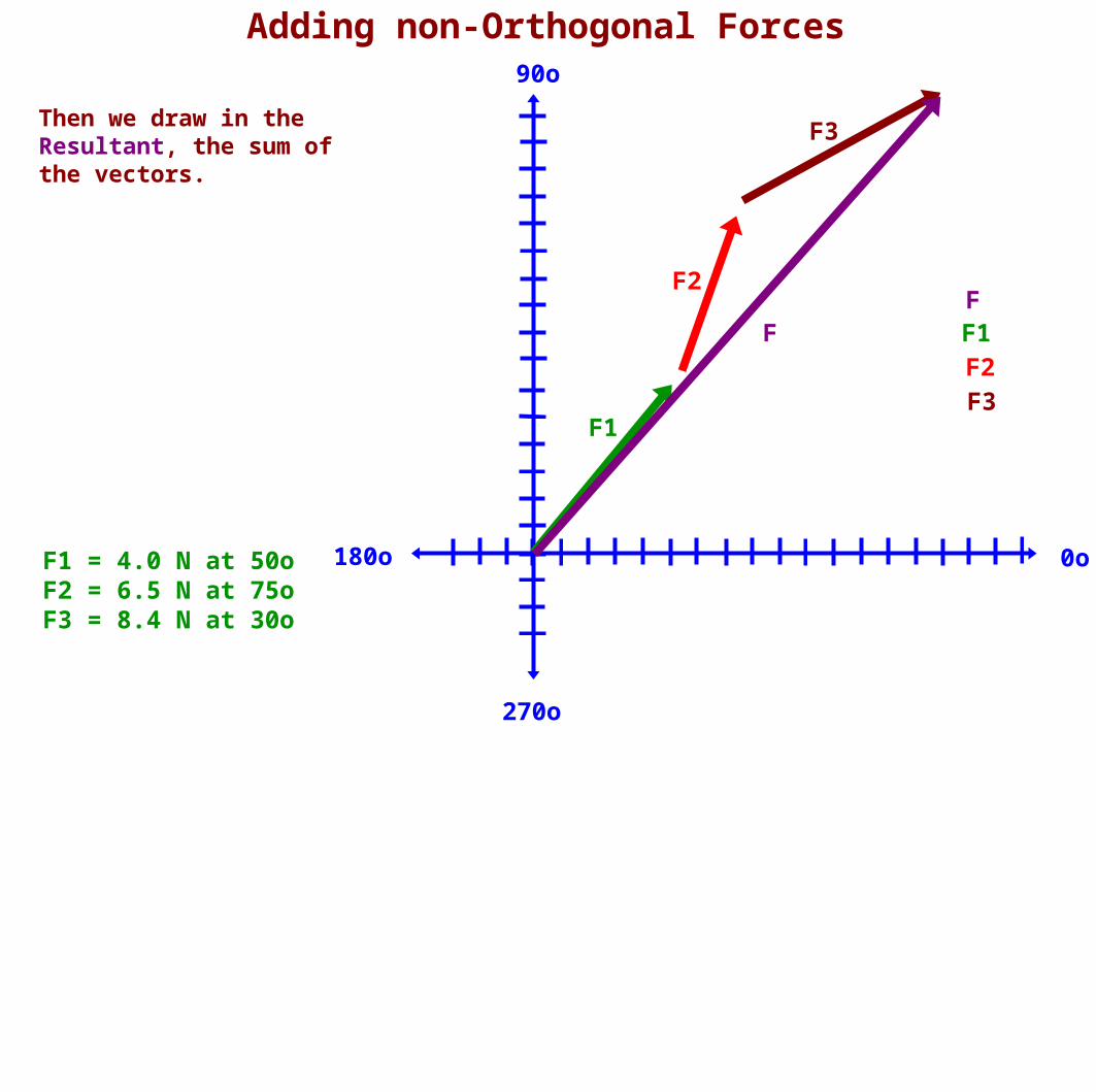
Adding non-Orthogonal Forces
F1 = 4.0 N at 50oF2 = 6.5 N at 75oF3 = 8.4 N at 30o
Then we draw in the Resultant, the sum of the vectors.
F1
F2
F3
F1 F2F3
F F

180o
90o
270o
0o
F1
F2
F3
F1x
F2x
F3x
F1y
F2y
F3y
F
Adding non-Orthogonal Forces
F1 = 4.0 N at 50oF2 = 6.5 N at 75oF3 = 8.4 N at 30o
Now, we graphically break each vector into its orthogonal components.

180o
90o
270o
0o
Adding non-Orthogonal Forces
F1 = 4.0 N at 50oF2 = 6.5 N at 75oF3 = 8.4 N at 30o
Then, we remove the original vectors and note that the sum of the components is the same as the sum of the vectors.
F1x
F2x
F3x
F1y
F2y
F3y
F

180o
90o
270o
0o
Adding non-Orthogonal Forces
F1 = 4.0 N at 50oF2 = 6.5 N at 75oF3 = 8.4 N at 30o
This is the key result:
The sum of the x-components of the vectors equals the x-component of the Resultant.
As it is for the y-components.
F1x F2x F3x
F1y
F2y
F3y
F Fy
Fx

Adding non-Orthogonal Forces
This explains how we will add vectors analytically.
1. Write the magnitude and direction (from 0 to 360 degrees) of each vector.
2. Compute the values of the x and y components.
3. Add the x components to find the x component of the Resultant.
4. Repeat for the y-components.
5. Use Pythagorean Theorem to find the magnitude of the Resultant.
6. Use Inverse Tangent to find the Resultant's direction.

Adding non-Orthogonal Forces
First make a table and enter what you know.
F1 = 8.0 N at 50oF2 = 6.5 N at 75oF3 = 8.4 N at 30o
Force Magnitude
Direction
x-comp. (Fcosθ)
y-comp. (Fsinθ)
F1
F2
F3
Fnet

Adding non-Orthogonal Forces
Then calculate the x and y components.
F1 = 8.0 N at 50oF2 = 6.5 N at 75oF3 = 8.4 N at 30o
Force Magnitude
Direction
x-comp. (Fcosθ)
y-comp. (Fsinθ)
F1 8.0 N 50o
F2 6.5 N 75o
F3 8.4 N 30o
Fnet

Adding non-Orthogonal Forces
Then add up the x and y components.
F1 = 8.0 N at 50oF2 = 6.5 N at 75oF3 = 8.4 N at 30o
Force Magnitude
Direction
x-comp. (Fcosθ)
y-comp. (Fsinθ)
F1 8.0 N 50o 5.14 N 6.13 N
F2 6.5 N 75o 1.68 N 6.28 N
F3 8.4 N 30o 7.27 N 4.2 N
Fnet

Adding non-Orthogonal Forces Then use Pythagorean Theorem and tan-1 to determine Fnet.
F1 = 8.0 N at 50oF2 = 6.5 N at 75oF3 = 8.4 N at 30o
Force Magnitude
Direction
x-comp. (Fcosθ)
y-comp. (Fsinθ)
F1 8.0 N 50o 5.14 N 6.13 N
F2 6.5 N 75o 1.68 N 6.28 N
F3 8.4 N 30o 7.27 N 4.20 N
Fnet 14.09 N
16.61 N

Adding non-Orthogonal Forces
Let's add together these three forces:
F1 = 8.0 N at 50oF2 = 6.5 N at 75oF3 = 8.4 N at 30o
Force Magnitude
Direction
x-comp. (Fcosθ)
y-comp. (Fsinθ)
F1 8.0 N 50o 5.14 N 6.13 N
F2 6.5 N 75o 1.68 N 6.28 N
F3 8.4 N 30o 7.27 N 4.20 N
Fnet 22.9 N 50o 14.09 N
16.61 N

Adding non-Orthogonal Forces
Now use the same procedure to add these forces.
DO NOT IGNORE NEGATIVE SIGNS
F1 = 21 N at 60oF2 = 65 N at 150oF3 = 8.4 N at 330o

Force
Magnitude
Direction
x-comp. (Fcosθ)
y-comp. (Fsinθ)
F1 21 N 60o
F2 65 N 150o
F3 45 N 330o
Fnet
Adding non-Orthogonal Forces
F1 = 21 N at 60oF2 = 65 N at 150oF3 = 8.4 N at 330o

Force
Magnitude
Direction
x-comp. (Fcosθ)
y-comp. (Fsinθ)
F1 21 N 60o 10.50 N 8.66 N
F2 65 N 150o -56.29 N 32.50 N
F3 45 N 330o 38.97 N -22.50 N
Fnet 131 N 290o -6.82 N 18.66 N
Answers
F1 = 21 N at 60oF2 = 65 N at 150oF3 = 8.4 N at 330o

17 Three forces act on an object. Which of the following is true in order to keep the object in translational equilibrium?I. The vector sum of the three forces must equal zero.II. The magnitude of the three forces must be equal.III. All three forces must be parallel.
A I only
B II only
C I and III only
D II and III only
E I, II, and III

Force and friction acting on an object
Previously, we solved problems with multiple forces, but they were either parallel or perpendicular.
For instance, draw the free body diagram of the case where a box is being pulled along a surface, with friction, at constant speed.

FN
mg
FAPPf
Now find the acceleration given that the applied force is 20 N, the box has a mass of 3.0kg, and the coefficient of kinetic friction is 0.20.
Force and friction acting on an object

FN
mg
FAPPf
FAPP = 20Nm = 3.0kgμk = 0.20
ΣF = ma
FN - mg = 0
FN = mg
FN = (3.0kg)(10m/s2)
FN = 30N
ΣF = ma
FAPP - fk = ma
FAPP - μkFN = ma
FAPP - μkmg = ma
a = (FAPP - μkmg)/m
a = (20N - (0.20)(30N))/3.0kg
a = (20N - 6.0N)/3.0kg
a = (14N)/3.0kg
a = 4.7 m/s2
x - axis y - axis
Force and friction acting on an object

Forces at angles acting on an object
Now we will solve problems where the forces act at an angle so that it is not parallel or perpendicular with one another.
First we do a free body diagram, just as we did previously.

FN
mg
FAPP
f
Forces at angles acting on an object
The next, critical, step is to choose axes.
Previously, we always used vertical and horizontal axes, since one axis lined up with the forces...and the acceleration.
Now, we must choose axes so that all the acceleration is along one axis, and there is no acceleration along the other.
You always have to ask, "In which direction could this object accelerate?" Then make one axis along that direction, and the other perpendicular to that.
What's the answer in this case?

FN
mg
FAPP
f
y
X
Forces at angles acting on an object
This time vertical and horizontal axes still work...since we assume the box will slide along the surface.
However, if this assumption is wrong, we will get answers that do not make sense, and we will have to reconsider our choice.

Forces at angles acting on an object
FN
mg
FAPP
f
Now we have to break any forces that do not line up with our axes into components that do.
In this case, FAPP, must be broken into
Fx and Fy
y
X

Forces at angles acting on an object
FN
mg
FAPP
f
y
X
Fy
Fx
Once we do that, we can now proceed as we did previously, using each component appropriately.

Let's use our work to find the acceleration if the applied force is 20 N at 37o above horizontal, the box has a mass of 3.0kg, and the coefficient of kinetic friction is 0.20.
Force and friction acting on an object
FN
mg
f
y
X
FAPP
Fy
Fx

FAPP = 20N at 37o m = 3.0kgμk = 0.20
Force and friction acting on an object
FN
mg
f
y
X
FAPP
FAPPy
FAPPx
ΣF = ma
FN + Fy - mg = 0
FN = mg - Fy
FN = mg - Fsinθ
FN = (3.0kg)(10m/s2) - (20N)(sin37o)
FN = 30N - 12N
FN = 18N
Note that FN is lower due to the force helping to support the object
ΣF = ma
Fx - fk = ma
Fx - μkFN = ma
Fcosθ - μkmg = ma
a = (Fcosθ - μkFN)/m
a = (20N cos37o - (0.20)(18N))/3.0kg
a = (16N - 3.6N)/3.0kg
a = (12.4N)/3.0kg
a = 4.1 m/s2
x - axis y - axis

Normal Force and Friction
Friction was reduced because the Normal Force was reduced; the box's weight, mg, was supported by the y-component of the force plus the Normal Force...so the Normal Force was lowered...lowering friction.
mg
FAPP
FAPPyFN
FN
Fy
mg
Just looking at the y-axis
ΣF = ma
FN + Fy - mg = 0
FN = mg - Fy
FN = mg - Fsinθ

Normal Force and Friction
What would happen with both the Normal Force and Friction in the case that the object is being pushed along the floor by a downward angled force?
FN
mg
FAPP
f
y
X

Normal Force and Friction
In this case the pushing force is also pushing the box into the surface, increasing the Normal Force as well as friction.
FN
mg
FAPP
f
y
XFy
Fx
FN
mg
Just looking at the y-axis
ΣF = ma
FN - Fy - mg = 0
FN = mg + Fy
FN = mg + FsinθFy

18 The normal force on the box is:
A mg
B mg sin(θ)
C mg cos(θ)
D mg + F sin(θ)
E mg – F sin(θ)
Fappθ

19 The frictional force on the box is:
Fappθ
A μ(mg + Fsin(θ))
B μ(mg - Fsin(θ))
C μ(mg + Fcos(θ))
D μ(mg - Fcos(θ))
E μmg

20 A block of mass m is pulled along a horizontal surface at constant speed v by a force Fapp , which acts at an angle of θ with the horizontal. The coefficient of kinetic friction between the block and the surface is μ.
The normal force exerted on the block by the surface is:
A mg - Fapp cosθ
B mg - Fapp sinθ
C mg
D mg + Fapp sinθ
E mg + Fapp cosθ
Fapp
θv
m
Fapp
θv
m
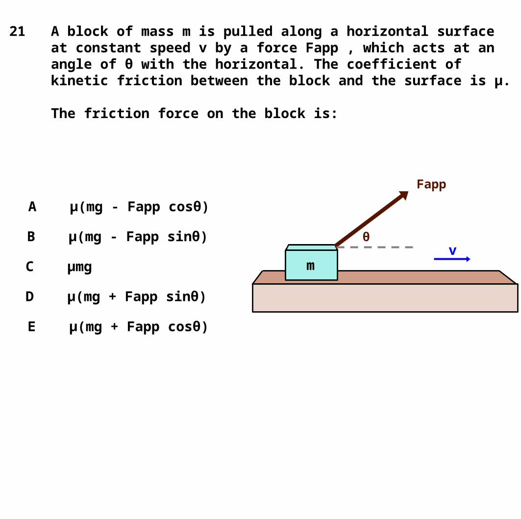
21 A block of mass m is pulled along a horizontal surface at constant speed v by a force Fapp , which acts at an angle of θ with the horizontal. The coefficient of kinetic friction between the block and the surface is μ.
The friction force on the block is:
A μ(mg - Fapp cosθ)
B μ(mg - Fapp sinθ)
C μmg
D μ(mg + Fapp sinθ)
E μ(mg + Fapp cosθ)

Normal Force and Weight
FN
mg
Previously we dealt mostly with horizontal (or, rarely, vertical surfaces). In that case FN, and mg were always along the same axis.
Now we will look at the more general case.

On the picture, draw the free body diagram for the block.
Show the weight and the normal force.
Inclined Plane

Inclined Plane
FN
mg
FN is ALWAYS perpendicular to the surface.
mg is ALWAYS directed downward.
But now, they are neither parallel or perpendicular to one another.

Choosing Axes
FN
mg
Previously, we used vertical and horizontal axes. That worked because problems always resulted in an acceleration that was along one of those axes.
We must choose axes along which all the acceleration is along one axis...and none along the other.

Choose of Axes
FN
mg
y
X
a
In this case, the block can only accelerate along the surface of the plane.
Even if there is no acceleration in a problem, this is the ONLY POSSIBLE direction of acceleration.
So we rotate our x-y axes to line up with the surface of the plane.

FN
mg
By the way, here's one way to see that θ is the both the angle of incline and the angle between mg and the new y-axis.
Inclined Plane Problems
y-axis
α
Let's name the angle of the inclined plane θ and the angle between mg and the x-axis θ' and show that θ = θ'
Since the angles in a triangle add to 180o, and the bottom left angle is 90o, that means:
α + θ = 90o
θ
θ'

FN
mg
Now look at the angles in the upper left corner of the triangle.
Inclined Plane Problems
y-axis
α
The surface of the inclined plane forms an angle of 180o, so
90o + θ' + α = 180o θ' + α = 90o
But we already showed that α + θ = 90o
θ' + α = 90o = α + θ
θ' = θ
θ
θ'

FN
mg
θ
a
We need to resolve all forces which don't align with an axis into components that will.
In this case, we resolve mg into its x and y components.
Inclined Plane Problems
FN
mg
mg sin θ
mg c
os
θ
θa
y
X
y
Xθ

Now we just use Newton's Second Law, which is true for each axis.
ΣFx = max
mgsinθ = max
a = gsinθ
down the plane
ΣFy = may
FN - mgcosθ = 0
FN = mgcosθ
FN
mg
mg sin θ
mg c
os
θ
θ a
y
X
Inclined Plane Problems
x - axis y - axis

A 5 kg block slides down a frictionless incline at an angle of 30 degrees.
a) Draw a free body diagram. b) Find its acceleration. (Use g = 10 m/s2)
θ
ΣFx = max
mg sin θ = ma
g sin θ = a
a = g sin θ
a = 10 m/s2 sin (30o) a = 10 m/s2 (0.5)
a = 5 m/s2
y
x
FN
mgmg sin θ
mg
cos
θ
θ
Answer

FN
mg
θ
fk
a
We can add kinetic friction to our inclined plane example. The kinetic friction points opposite the direction of motion.
We now have a second vector along the x axis. fk points in the negative direction (recall fk = μk FN)
Inclined Plane Problems with Friction
y
x
FN
mg
mg sinθ
mg c
osθ
θ
fka

ΣFx = max
mgsinθ - fk = ma
mgsinθ - μkFN = ma
mgsinθ - μkmgcosθ = ma
gsinθ - μkgcosθ = a
a = gsinθ - μkgcosθ
a = g(sinθ - μk cosθ)
Inclined Plane Problems with Friction
y
x
FN
mg
mg sinθ
mg c
osθ
θ
fka
ΣFy = mayFN = mg cosθ
x - axis y - axis

The general solution for objects sliding down an incline is:
a = g(sinθ - μkcosθ)
Note, that if there is no friction:
μk = 0
and we get our previous result for a frictionless plane:
a = gsinθ
Inclined Plane Problems with Friction

a = g(sinθ - μkcosθ)
If the object is sliding with constant velocity: a = 0
Inclined Plane Problems with Friction
a = g(sinθ - μkcosθ)
0 = g(sinθ - μkcosθ)
0 = sinθ - μkcosθ
μk cosθ = sinθ
μk = sinθ / cosθ
μk = tanθ
a = 0
y
x
FN
mg
mg sinθ
mg c
osθ
θ
fk

Inclined Plane with Static Friction
We just showed that for an object sliding with constant velocity down an inclined plane that:
μk = tanθ
Similarly, substituting μs for μk (at the maximum static force; the largest angle of incline before the object begins to slide) than:
μs = tanθmax
But this requires that the MAXIMUM ANGLE of incline, θmax, be used to determine μs.
a = 0
y
x
FN
mg
mg sinθ
mg c
osθ
θ
fs

A 5 kg block slides down a incline at an angle of 30o with a constant speed.
a) Draw a free body diagram.b) Find the coefficient of friction between the block and the incline. (Use g = 10 m/s2)
θ ΣF = ma
mg sin θ - fK = 0
mg sin θ = fK
mg sin θ = μ FN
mg sin θ = μ mg cos θ
μ = mg sin θ / mg cos θ
μ = tan θ
μ = tan 30 = 0.58
y
x
FN
mgmg sin θ
mg
cos
θ
θ
fk
Answer

A 5 kg block is pulled up an incline at an angle of 30o at a constant velocity The coefficient of friction between the block and the incline is 0.3.
a) Draw a free body diagram.b) Find the applied force. (Use g = 10 m/s2)
FN
mg
mg sin θ
mg
cos
θ
θ
Fapp
fK
a = 0
θ
y-directionΣF = ma
FN - mg cos θ = 0
FN = mg cos θ
x-directionΣF = ma
Fapp - mg sin θ - fk = ma
Fapp - mg sin θ -μk FN = 0
Fapp = mg sin θ + μk mg cos θ
Fapp = 38 N
Answer

θ
A 5 kg block is pulled UP an incline at an angle of 30 degrees with a force of 40 N. The coefficient of friction between the block and the incline is 0.3.
a) Draw a free body diagram.b) Find the block's acceleration. (Use g = 10 m/s2)
FN
mg
mg sin θ
mg
cos
θ
θ
FappfK
a
y-axisΣF = ma
FN - mg cos θ = 0
FN = mg cos θ
x-axisΣF = ma
Fapp - mg sin θ - fk = ma
Fapp - mg sin θ - μk FN = ma
Fapp - mg sin θ - μk mg cos θ = ma
a = (Fapp/m) - g sin θ - μk g cos θ
a = 0.4 m/s2

FN
mg
θ
a
If a mass, m, slides down a frictonless inclined plane, we have this general setup:
Inclined Plane Problems
y
x
It is helpful to rotate our reference frame so that the +x axis is parallel to the inclined plane and the +y axis points in the direction of FN.

A 5 kg block remains stationary on an incline. The coefficients of static and kinetic friction are 0.4 and 0.3, respectively. a) Draw a free body diagram.b) Determine the angle that the block will start to move. (Use g = 10 m/s2)
FN
mg
mg sin θ
mg
cos
θ
θ
fs
a = 0
y-directionΣF = ma
FN - mg cos θ = 0
FN = mg cos θ
x-directionΣF = ma
fs = mg sin θ
μs mg cos θ = mg sin θ
μs cos θ = sin θ
μs = sin θ / cos θ
μs = tan θ
θ = tan-1 μs
θ = 21.8o
θ

22 A block of mass m slides down a rough incline as shown. Which free body diagram correctly shows the forces acting on the block?
A B C D E
f
W
N
f
W
N
f
W
N
f
W
Nf
W
N

23 A block with a mass of 15 kg slides down a 43° incline as shown above with an acceleration of 3 m/s2.
What is the normal force N appliedby the inclined plane on the block?
A 95 N
B 100 N
C 105 N
D 110 N
E 115 N

24 A block with a mass of 15 kg slides down a 43° incline as shown above with an acceleration of 3 m/s2.
The magnitude of the frictional force along the plane is nearly:
A 56 N
B 57 N
C 58 N
D 59 N
E 60 N

Static Equilibrium
There is a whole field of problems called "Statics" that has to do with cases where no acceleration occurs, objects remain at rest.
Anytime we construct something (bridges, buildings, houses, etc.) we want them to remain stationary, not accelerate. So this is a very important field.
The two types of static equilibrium are with respect to linear and rotational acceleration, a balancing of force and of torque (forces that cause objects to rotate). We'll look at them in that order.

Previously, we did problems where a rope supporting an object exerted a vertical force straight upward, along the same axis as the force mg was pulling it down. That led to the simple case that if a = 0, then FT = mg
Tension Force
mg
FT

25 A uniform rope of weight 20 N hangs from a hook as shown above. A box of mass 60 kg is suspended from the rope. What is the tension in the rope?
A 20 N throughout the rope
B 120 N throughout the rope
C 200 N throughout the rope
D 600 N throughout the rope
E It varies from 600 N at the bottom of the rope to 620 N at the top.

But it is possible for two (or more) ropes to support an object (a = 0) by exerting forces at angles. In that case:
The vertical components of the force exerted by each rope must add up to mg.
And the horizontal components must add to zero.
Tension Force
mg
T1T2

So we need to break the forces into components that align with our axes.
Tension Force
mg
T1
T2y
X
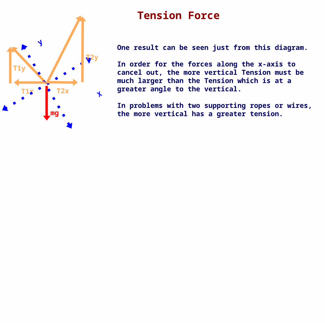
One result can be seen just from this diagram.
In order for the forces along the x-axis to cancel out, the more vertical Tension must be much larger than the Tension which is at a greater angle to the vertical.
In problems with two supporting ropes or wires, the more vertical has a greater tension.
Tension Force
mg
T1x T2x
y
X
T2y
T1y

Let's calculate the tension in two ropes if T1 is at an angle of 50o from the vertical and T2 is at an angle of 20o from the vertical and they are supporting a 8.0 kg mass.
Note, that in this case the horizontal component is given by Tsinθ, where before it was given by Tcosθ.
To know which function to use you MUST draw the diagram and find the sides opposite and adjacent to the given angle.
Tension Force
50o
50o 20o
20o
mg
T1x T2x
y
X
T2y
T1y

Tension Force
ΣFx = max = 0
T1x - T2x = 0
T1sinθ1 = T2sinθ2
T1 = T2sinθ2/sinθ1
T1 = T2 (sin20o/sin50o)
T1 = T2 (0.34/0.77)
T1 = 0.44 T2
T1 = 0.44 (64N)
T1 = 28N
ΣFy = may = 0
T1y + T2y - mg = 0
T1cosθ1 + T2cosθ2 = mg
(0.44T2)cos(50o) + T2cos(20o) = mg
(0.44T2)(0.64) + T2(0.94) =(8kg)(9.8m/s2)
1.22 T2 = 78N
T2 = 78N / 1.22
T2 = 64N
x - axis y - axis
50o
50o 20o
20o
mg
T1x T2x
y
X
T2y
T1y

Tension Force
θ
mg
Tx Tx
y
X
TyTy
θ
θ
θ
If the ropes form equal angles to the vertical, the tension in each must also be equal, otherwise the x-components of Tension would not add to zero.

Tension Force
θ
mg
Tx Tx
y
X
TyTy
θ
θ
θ
ΣFx = max = 0
T1x - T2x = 0
Tsinθ = Tsinθ
which just confirms that if the angles are equal, the tensions are equal
ΣFy = may = 0
T1y + T2y - mg = 0
Tcosθ + Tcosθ = mg
2Tcosθ = mg
T = mg / (2cosθ)
Note that the tension rises as cosθ becomes smaller...which occurs as θ approaches 90o.
It goes to infinity at 90o, which shows that the ropes can never be perfectly horizontal.
x - axis y - axis

26 A lamp of mass m is suspended from two ropes of unequal length as shown above. Which of the following is true about the tensions T1 and T2 in the cables?
A T1 > T2
B T1 = T2
C T1 < T2
D T1 - T2 = mg
E T1 + T2 = mg
T1T2

27 A large mass m is suspended from two massless strings of an equal length as shown below. The tension force in each string is:
A ½ mg cos(θ)
B 2 mg cos(θ)
C mg cos(θ)
D mg/cos(θ)
E mg/2cos(θ)
θ θ
m

Torque and Rotational Equilibrium
Forces causes objects to linearly accelerate.
Torque causes objects to rotationally accelerate.
Rotational dynamics is a major topic of AP Physics C: Mechanics. It isn't particularly difficult, but for AP B, we only need to understand
the static case, where all the torques cancel and add to zero.
First we need to know what torque is.

Torque and Rotational Equilibrium
Until now we've treated objects as points, we haven't been concerned with their shape or extension in space.
We have assumed that any applied force acts through the center of the object and it is free to accelerate. That does not result in rotation, just linear acceleration.
But if the force acts on an object so that it causes the object to rotate around its center of mass...or around a pivot point, that force has exerted a torque on the object.

Torque and Rotational Equilibrium
A good example is opening a door, making a door rotate. The door does not accelerate in a straight line, it rotates around its hinges.
Think of the best direction and location to push on a heavy door to get it to rotate and you'll have a good sense of how torque works.
Which force (blue arrow) placed at which location would create the most rotational acceleration of the green door about the black hinge?

Torque and Rotational Equilibrium
The maximum torque is obtained from:
The largest forceAt the greatest distance from the pivotAt an angle to the line to the pivot that is closest to perpendicular
Mathematically, this becomes:
τ = Frsinθ
τ (tau) is the symbol for torque; F is the applied forcer is the distance from the pivotθ is the angle of the force to a line to the pivot

Torque and Rotational Equilibrium
τ = Frsinθ
When r decreases, so does the torque for a given force. When r = 0, τ = 0.
When θ differs from 90o, the torque decreases. When θ = 0o or 180o, τ = 0.
r
θ
F
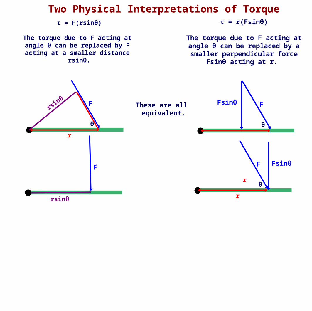
Two Physical Interpretations of Torqueτ = r(Fsinθ)
The torque due to F acting at angle θ can be replaced by a smaller perpendicular force
Fsinθ acting at r.
r
θ
F
τ = F(rsinθ)
The torque due to F acting at angle θ can be replaced by F
acting at a smaller distance rsinθ.
r
θ
FFsinθ
r
F
θ
Fsinθ
rsin
θ
F
rsinθ
These are all equivalent.

Rotational Equilibrium
When the sum of the torques on an object is zero, the object is in rotational equilibrium.
Define counter clockwise (CCW) as the positive direction for rotation and clockwise (CW) as the negative.
For instance, what perpendicular force, F, must be applied at a distance of 7.0 m for the pivot to exactly offset a 20N force acting at a distance of 4.0m from the pivot of a door at an angle of 30o?
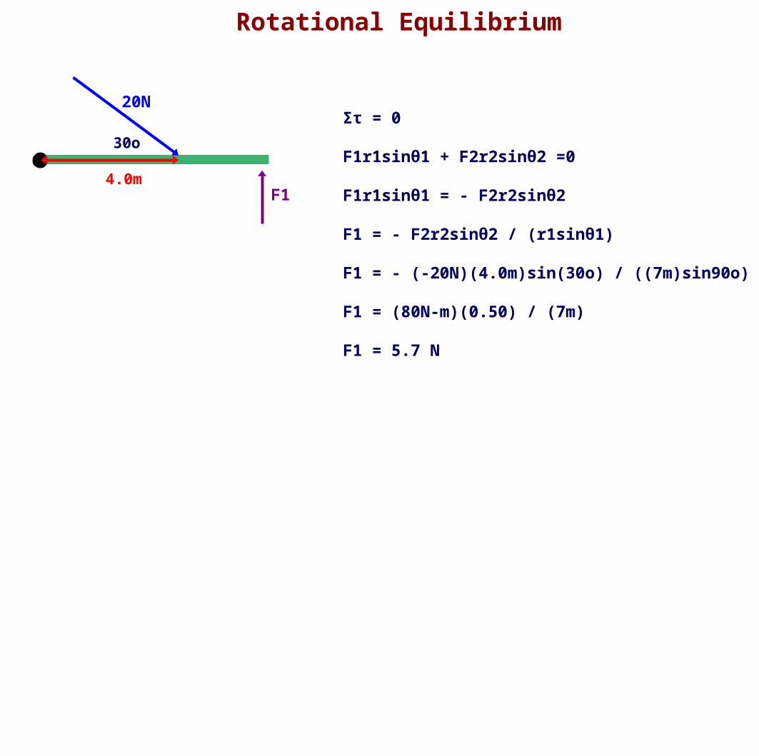
Rotational Equilibrium
20N
30o
4.0mF1
Στ = 0
F1r1sinθ1 + F2r2sinθ2 =0
F1r1sinθ1 = - F2r2sinθ2
F1 = - F2r2sinθ2 / (r1sinθ1)
F1 = - (-20N)(4.0m)sin(30o) / ((7m)sin90o)
F1 = (80N-m)(0.50) / (7m)
F1 = 5.7 N

Rotational Equilibrium
1.0m3.0m 4.0m
4kg 2kg
What mass must be added at distance 4.0m to put the above apparatus into equilibrium?

Rotational Equilibrium
1.0m3.0m 4.0m
4kg 2kg
Στ = 0
F1r1sinθ1 + F2r2sinθ2 - F3r3sinθ2 = 0
m1gr1 + m2gr2 - m3gr3 = 0
m1r1 + m2r2 - m3r3 = 0
m3 = (m1r1 + m2r2) / r3
m3 = ((4kg)(3m) +(2kg)(1m)) / 4m
F1 = (14kg-m)) / (4m)
F1 = 3.5 kg

A 12 kg load hangs from one end of a rope that passes over a small frictionless pulley. A 15 kg counterweight is suspended from the other end of the rope. The system is released from rest.
a. Draw a free-body diagram for each object showing all applied forces in relative scale. Next to each diagram show the direction of the acceleration of that object.
b. Find the acceleration each mass.
c. What is the tension force in the rope?
d. What distance does the 12 kg load move in the first 3 s?
e. What is the velocity of 15 kg mass at the end of 5 s?
12 kg
15 kg

12 kg
15 kg
m1 = 12 kgm2 = 15 kg
a. m1
m1g
FT
m2
m2g
FT
a a
b. ΣF = ma ΣF = FT - m1g = m1a FT = m1g + m1a
ΣF = FT - m2g = -m2a FT = m2g - m2a
FT = FT m1g + m1a = m2g - m2a m1a + m2a = m2g - m1g a(m1 + m2) = g(m2 - m1)
a = (g(m2 - m1)) / (m1 + m2) = (10 m/s2 (15kg - 12kg)) / (12kg + 15kg) = 30 m/s2 * kg / 27kg a = 1.11 m/s2
c. FT = m1g + m1a or FT = m2g - m2a FT = m1g + m1a = 12kg(10 m/s2) + 12kg(1.11 m/s2) = 120 N + 13.33 N = 133.33 N
FT = m2g - m2a = 15kg(10 m/s2) - 15kg(1.11 m/s2) = 150 N - 16.67 N = 133.33 N

12 kg
15 kg
m1 = 12 kgm2 = 15 kgd. x = xo + vot + 1/2 at2
xo = 0 vo = 0 x = 1/2 at2 = 1/2 (1.11 m/s2)(3s)2 = 5 m
e. v = vo + at vo = 0 v = at = (1.11 m/s2)(5s) = 5.55 m/s

A 500 g block lies on a horizontal tabletop. The coefficient of kinetic friction between the block and the surface is 0.25. The block is connected by a massless string to the second block with a mass of 300 g. The string passes over a light frictionless pulley as shown above. The system is released from rest.
a. Draw clearly labeled free-body diagrams for each of the 500 g and the 300g masses. Include all forces and draw them to relative scale. Draw the expected direction of acceleration next to each free-body diagram.
b. Use Newton’s Second Law to write an equation for the 500 g mass.
c. Use Newton’s Second Law to write an equation for the 300 g mass.
d. Find the acceleration of the system by simultaneously solving the system of two equations.
e. What is the tension force in the string?
500 g
300 g

a.
FT
FT
FN
m2gm1g
f a
a
m1 = 500 g = 0.5 kgm2 = 300 g = 0.3 kgμ = 0.25
b. ΣF = ma x-direction ΣF = FT - f = m1a f = μFn f = μm1g
y-direction ΣF = ma = 0 ΣF = FN - m1g = 0 FN = m1g
c. ΣF = ma ΣF = FT - m2g = - m2a
d. FT - f = m1a FT - m2g = - m2a FT = f + m1a FT = m2g - m2a
f + m1a = m2g - m2a m1a + m2a = m2g - f a(m1 + m2) = m2g - f
a = (m2g - f) / (m1 + m2) = (m2g - μm1g) / (m1 + m2) = ((0.3kg)(10 m/s2) - (0.25)(0.5kg)(10m/s2)) / (0.5kg +0.3kg) = (3 - 1.25) kg*m/s2 / (0.8 kg) = 2.1875 m/s2
e. FT = f + m1a or FT = m2g - m2a FT = μm1g + m1a FT = (0.25)(0.5kg)(10m/s2) + 0.5kg(2.1875 m/s2) = 2.34 N
FT = m2g - m2a FT = 0.3kg(10m/s2) - 0.3kg(2.1875 m/s2) = 2.34 N

A 10-kilogram block is pushed along a rough horizontal surface by a constant horizontal force F as shown above. At time t = 0, the velocity v of the block is 6.0 meters per second in the same direction as the force. The coefficient of sliding friction is 0.2. Assume g = 10 meters per second squared.
a. Calculate the force F necessary to keep the velocity constant.
F

m = 10 kgv = 6 m/s
μ = 0.2g = 10 m/s2
a. Calculate the force F necessary to keep the velocity constant.
Fappfk
FN
mg
x y
ΣF = ma ΣF = FN - mg = 0Fapp - fk = 0 FN = mgFapp = fkFapp = μFNFapp = μmg
Fapp = (0.2)(10kg)(10m/s2)
Fapp = 20 N

A helicopter holding a 70-kilogram package suspended from a rope 5.0 meters long accelerates upward at a rate of 5 m/s2. Neglect air resistance on the package.
a. On the diagram, draw and label all of the forces acting on the package.
b. Determine the tension in the rope.
c. When the upward velocity of the helicopter is 30 meters per second, the rope is cut and the helicopter continues to accelerate upward at 5 m/s2. Determine the distance between the helicopter and the package 2.0 seconds after the rope is cut.

mg
FT
a
a. On the diagram, draw and label all of the forces acting on the package.
b. Determine the tension in the rope.
ΣF = ma
FT - mg = maFT = mg + maFT = m (g+a)
FT = (70kg) (10 m/s2 + 5 m/s2)FT = (70kg) (15 m/s2)FT = 1050 N
m = 70 kga = 5 m/s2x = 5 m

m = 70 kga = 5 m/s2x = 5 mv = 30 m/s
c. When the upward velocity of the helicopter is 30 meters per second, the rope is cut and the helicopter continues to accelerate upward at 5.2 m/s2. Determine the distance between the helicopter and the package 2 seconds after the rope is cut.
ahelicopter
apackage
Method 1
Use the reference frame of the package after it is released.
The relative acceleration of the helicopter is given by:
arelative = ahelicopter - apackagearelative = 5 m/s2 - (-10 m/s2)arelative = 15 m/s2
Their relative initial velocity is zero, since they are connected together
The helicopter is 5.0 m above the package when released, the length of the rope.
y = y0 + v0 + 1/2at2y = 5m + 0 + 1/2(15 m/s2)(2s)2y= 35m

Method 2
Use the reference frame of the earth, but use the initial height of the package as zero.
Package Helicopter y = y0 + v0t+ 1/2at2 y = y0 + v0t+ 1/2at2y = 0 + (30 m/s)(2s) + 1/2(-10 m/s2)(2s)2 y = 5m + (30 m/s)(2s) + 1/2(+5 m/s2)(2s)2y= 60 m - 20 m y= 5m + 60 m + 10 my= 40 m y= 75 m
Their separation is just the difference in their positions
Δy = yhelicopter - ypackageΔy = 75m - 40mΔy = 35m
m = 70 kga = 5 m/s2x = 5 mv = 30 m/s
c. When the upward velocity of the helicopter is 30 meters per second, the rope is cut and the helicopter continues to accelerate upward at 5.2 m/s2. Determine the distance between the helicopter and the package 2 seconds after the rope is cut.
ahelicopter
apackage

Three blocks of masses 1.0, 2.0, and 4.0 kilograms are connected by massless strings, one of which passes over a frictionless pulley of negligible mass, as shown above. Calculate each of the following.
a. The acceleration of the 4-kilogram block
b. The tension in the string supporting the 4-kilogram block
c. The tension in the string connected to the l-kilogram block
1 kg
2 kg
4 kg

m1 = 1 kgm2 = 2 kgm3 = 4 kgg = 9.8 m/s2
a. The acceleration of the 4-kilogram block ΣF = ma
m1: m2: m3:FT1 = m1a FT2 - FT1 = m2a FT2 - m3g = -m3a
FT2 - m1a = m2a FT2 - m3g = -m3a FT2 = m1a + m2a FT2 = m3g - m3a m1a + m2a = m3g - m3am1a + m2a + m3a = m3ga(m1 + m2 + m3) = m3ga = m3g / (m1 + m2 + m3)a = (4kg)(9.8 m/s2) / (1kg + 2kg + 4kg)a = 5.6 m/s2
4 kg
1 kg
2 kg
FN FN
m1g m2gm3g
FT1 FT1 FT2
FT2
a
aa

m1 = 1 kgm2 = 2 kgm3 = 4 kgg = 9.8 m/s2
b. The tension in the string supporting the 4-kilogram block
FT2 = m1a + m2a FT2 = 1kg(5.6 m/s2) + 2kg(5.6 m/s2)FT2 = 16.8 N
or
FT2 = m3g - m3aFT2 = 4kg(9.8 m/s2) - 4kg(5.6 m/s2)FT2 = 16.8 N
c. The tension in the string connected to the l-kilogram block
FT1 = m1aFT1 = 1kg(5.6 m/s2)FT1 = 5.6 N

A 10-kilogram block rests initially on a table as shown in cases I and II above. The coefficient of sliding friction between the block and the table is 0.2. The block is connected to a cord of negligible mass, which hangs over a massless frictionless pulley. In case I a force of 50 newtons is applied to the cord. In case II an object of mass 5 kilograms is hung on the bottom of the cord. Use g = 10 meters per second squared.
a. Calculate the acceleration of the 10-kilogram block in case I.
b. On the diagrams below, draw and label all the forces acting on each block in case II
c. Calculate the acceleration of the 10-kilogram block in case II.
d. Calculate the tension force in case II.
F
Case I
10 kg
10 kg
5 kg
Case II

m1 = 10 kgm2 = 5 kg μ = 0.2 FApp = 50 Ng = 10 m/s2
a. Calculate the acceleration of the 10-kilogram block in case I.
ΣF = maFApp - fK = maFApp - μmg = maa = (FApp - μmg)/ma = (50N - 0.2(10kg)(10m/s2))/10kga = 3 m/s2
y
ΣF = ma ΣF = FN - mg = 0FN = mgfk = μFNfk = μmg
b. On the diagrams below, draw and label all the forces acting on each block in case II
FN
m1g
f
FT
FT
m2g
5 kg10 kg

m1 = 10 kgm2 = 5 kg μ = 0.2 FApp = 50 Ng = 10 m/s2
c. Calculate the acceleration of the 10-kilogram block in case II.
ΣF = maFT - f = m1a FT - m2g = -m2aFT - μm1g = m1a FT = m2g - m2aFT = μm1g + m1a
μm1g + m1a = m2g - m2am1a + m2a = m2g - μm1g
a(m1 + m2) = g(m2 - μm1)
a = g(m2 - μm1)/(m1 + m2) = 10 m/s2(5kg - 0.2*10kg)/(5kg +10kg) a = 2 m/s2
d. Calculate the tension force in case II.
FT - m2g = -m2aFT = m2g - m2a
FT = m2(g - a) = 5kg (10 m/s2 - 2 m/s2) = 40 N
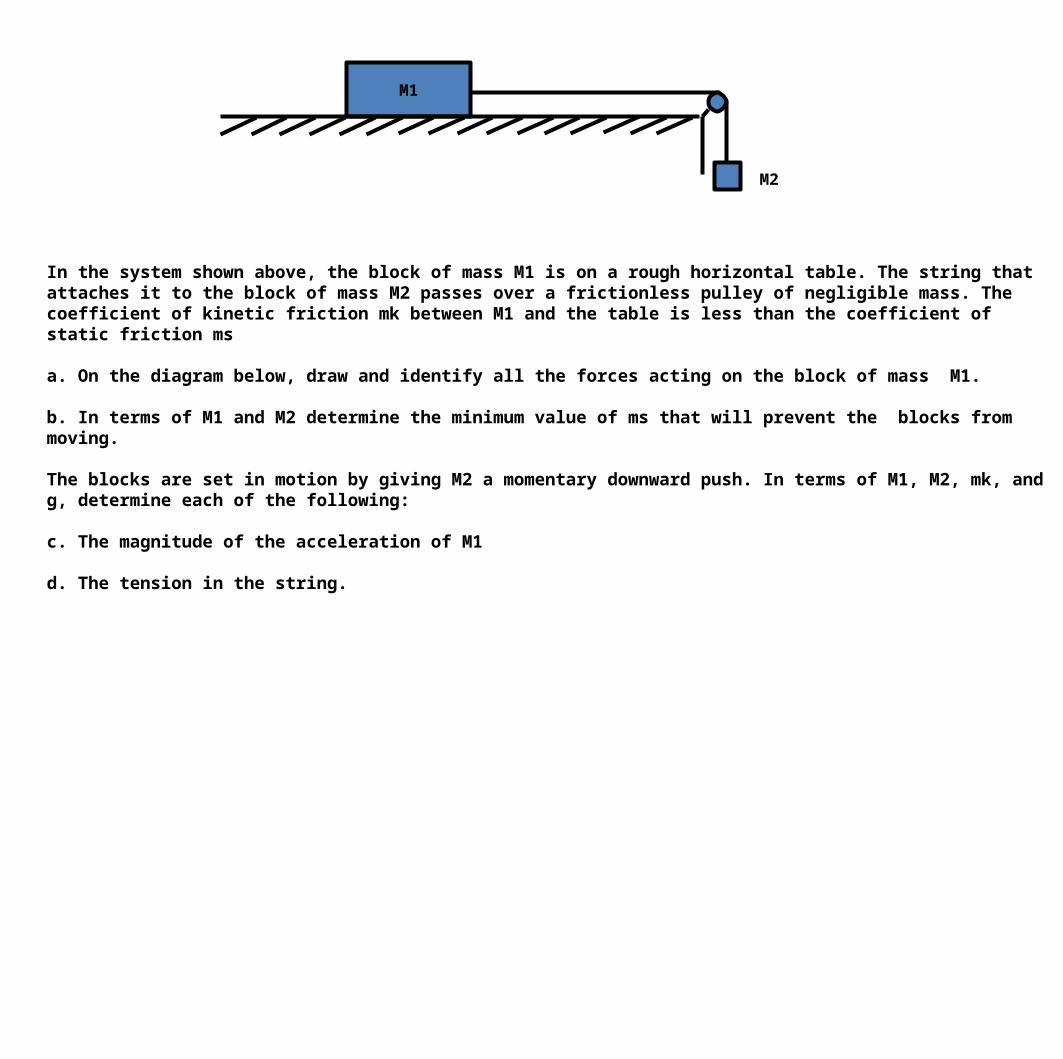
In the system shown above, the block of mass M1 is on a rough horizontal table. The string that attaches it to the block of mass M2 passes over a frictionless pulley of negligible mass. The coefficient of kinetic friction mk between M1 and the table is less than the coefficient of static friction ms
a. On the diagram below, draw and identify all the forces acting on the block of mass M1.
b. In terms of M1 and M2 determine the minimum value of ms that will prevent the blocks from moving.
The blocks are set in motion by giving M2 a momentary downward push. In terms of M1, M2, mk, and g, determine each of the following:
c. The magnitude of the acceleration of M1
d. The tension in the string.
M1
M2

a. On the diagram below, draw and identify all the forces acting on the block of mass M1.
b. In terms of M1 and M2 determine the minimum value of ms that will prevent the blocks from moving.
The pulley system is not moving, so acceleration is zero. ΣF = max-direction for M1: FT - f = 0 FT = f y-direction for M1: FN - M1g = 0 FN = M1g
y-direction for M2: FT - M2g = 0 FT = M2g
f = μsFN or msFN in this casef = msM1g = M2g
ms = M2 / M1
M1g
FN
FTf
M1, M2, mk, ms, g

The blocks are set in motion by giving M2 a momentary downward push. In terms of M1, M2, mk, and g, determine each of the following:
c. The magnitude of the acceleration of M1
ΣF = max-direction for M1: FT - f = M1a FT = f + M1ay-direction for M1: FN - M1g = 0 FN = M1gf = μkFN or mkFN in this casef = mkM1g
y-direction for M2: FT - M2g = -M2a FT = M2g - M2a
FT = f + M1a, FT = M2g - M2amkM1g + M1a = M2g - M2aM1a + M2a = M2g - mkM1ga(M1 + M2) = M2g - mkM1ga = M2g - mkM1g / (M1 + M2)
d. The tension in the string.FT = f + M1a or FT = M2g - M2aFT = mkM1g + M1(M2g - mkM1g / (M1 + M2) ) orFT = M2g - M2(M2g - mkM1g / (M1 + M2) )

Two 10-kilogram boxes are connected by a massless string that passes over a massless frictionless pulley as shown above. The boxes remain at rest, with the one on the right hanging vertically and the one on the left 2.0 meters from the bottom of an inclined plane that makes an angle of 60° with the horizontal. The coefficients of kinetic friction and static friction between the Ieft-hand box and the plane are 0.15 and 0.30, respectively. You may use g = 10 m/s2, sin 60° = 0.87, and cos 60° = 0.50.
a. What is the tension FT in the string.
b. On the diagram above, draw and label all the forces acting on the box that is on the plane.
c. Determine the magnitude of the frictional force acting on the box on the plane.
d. The string is then cut and the left-hand box slides down the inclined plane. What is the magnitude of its acceleration?
m1
m2
2 m
60o

m1 = 10 kgm2 = 10 kg x = 2 mθ = 60o , sin 60° = 0.87, cos 60° = 0.50μk = 0.15, μs = 0.30g = 10 m/s2
a. What is the tension FT in the string.
The acceleration is 0 because the system is not moving.
ΣF = max-direction for m1: FT - f - m1gsinθ = 0 FT = f + m1gsinθy-direction for m1: FN - m1gcosθ = 0 FN = m1gcosθ
f = μsFN f = μsm1gcosθ
FT = f + m1gsinθ FT = μsm1gcosθ + m1gsinθFT = (0.30)(10kg)(10 m/s2)(0.50) + (10kg)(10 m/s2)(0.87)FT = 102 N

m1 = 10 kgm2 = 10 kg x = 2 mθ = 60o , sin 60° = 0.87, cos 60° = 0.50μk = 0.15, μs = 0.30g = 10 m/s2
b. On the diagram above, draw and label all the forces acting on the box that is on the plane.
c. Determine the magnitude of the frictional force acting on the box on the plane.
y-direction for m1: FN - m1gcosθ = 0 FN = m1gcosθ
f = μsFN f = μsm1gcosθf = 0.30(10kg)(10 m/s2)(0.50)f = 15 N
m1
FN
f
m1g
FT
60o

m1 = 10 kgm2 = 10 kg x = 2 mθ = 60o , sin 60° = 0.87, cos 60° = 0.50μk = 0.15, μs = 0.30g = 10 m/s2
d. The string is then cut and the left-hand box slides down the inclined plane. What is the magnitude of its acceleration?
ΣF = max-direction of m1: f - m1gsinθ = -m1a y-direction for m1: FN - m1gcosθ = 0 FN = m1gcosθ
f = μkFN = μkm1gcosθ
m1a = m1gsinθ - fa = (m1gsinθ - μkm1gcosθ) / m1 a = ((10kg)(10 m/s2)(0.87) - (0.15)(10kg)(10 m/s2)(0.50)) / 10kga = 7.95 m/s2
m1
m2
60oa
fFN
m1g

Masses ml and m2, are connected by a light string. They are further connected to a block of mass M by another light string that passes over a pulley. Blocks l and 2 move with a constant velocity v down the inclined plane, which makes an angle θ with the horizontal. The kinetic frictional force on block 1 is f and that on block 2 is 2f.
a. On the figure above, draw and label all the forces on block m1, m2, and M.
Express your answers to each of the following in terms of ml, m2, g, θ, and f.
b. Determine the coefficient of kinetic friction between the inclined plane and block 1.
c. Determine the value of the suspended mass M that allows blocks 1 and 2 to move with constant velocity down the plane.
d. The string between blocks 1 and 2 is now cut. Determine the acceleration of block 1 while it is on the inclined plane.
m1
m2
Mv
θ

m1
m2
Mv
θ
a. On the figure above, draw and label all the forces on block m1, m2, and M.
m1
vm1g
FT1f
FN
a = 0m2v
m2g
FT2f
FN
a = 0
FT1
M
Mg
FT2
θ θ
v
a = 0

Express your answers to each of the following in terms of ml, m2, g, θ, and f.
b. Determine the coefficient of kinetic friction between the inclined plane and block 1.
f = μFNΣF = maFN - m1gcosθ = 0FN = m1gcosθf = μm1gcosθ
μ = f /(m1gcosθ)
c. Determine the value of the suspended mass M that allows blocks 1 and 2 to move with constant velocity down the plane.
m1: ΣF = ma M: FT2 - Mg = 0 FT1 - m1gsinθ - f = 0 FT2 = Mg FT1 = m1gsinθ
m2: ΣF = ma FT2 - FT1 - m2gsinθ - 2f = 0 Mg - m1gsinθ - f - m2gsinθ - 2f = 0 Mg = m1gsinθ + m2gsinθ + 3f M = (m1gsinθ + m2gsinθ + 3f) / g

d. The string between blocks 1 and 2 is now cut. Determine the acceleration of block 1 while it is on the inclined plane.
x-direction: ΣF = ma f - m1gsinθ = -m1a m1gsinθ - f = m1a a = (m1gsinθ - f) / m1
m1
m1g
f
FN
a
θ

Calculus Based

Fluid Resistance
v
Fresistance
When first learning dynamics discussed cases in which an object moves with any friction. Then we began to take the frictional force into account between an object and its surface. Now we are going to begin taking into account air resistance.

a
t
g
t
v
y
t
Fluid Resistance
No resistance
v = vo + gtvo = 0
a is constant
v increasing
mg = ma
a = g

Fluid Resistance
If we do not take into account air resistance then the object will fall with a constant acceleration.
If air resistance however is taken into account then the objects acceleration will eventually be cancelled out by the drag force.
Since the acceleration will essentially become zero, at some point in time your velocity will be constant.

With resistance
FR
FR
a=g
vo=0
Fluid Resistance
When the falling object stops accelerating it reaches its terminal velocity.
In this example the equation for the resistive force is given as F = kv, but in other problems the resisitive force equation can be different.

28 If the equation for the force due to air resistance is kv2. What is the terminal velocity reached by the object?
A
B
C
D
E

Velocity with respect to Time

Graphical Representation of the Fluid Resistance Equation
x
t
a
t
v
t

v
t
29 Which of these is the graph that best represents the general velocity versus time for air resistance?
A B
C D
v
t
v
t t
v

We have learned before that distance is the integral of velocity so by integrating the velocity equation we were able to come up with the distance equation.

30 Which of these is the graph that best represents the general position versus time for air resistance?
A B
CD x
t
x
t
x
t
t
x

The final equation shows how acceleration approaches zero.

31 Which of these is the graph that best represents the general acceleration versus time for air resistance?
A B
C D a
t
a
t
a
t
t
a