Embed Size (px)
Citation preview
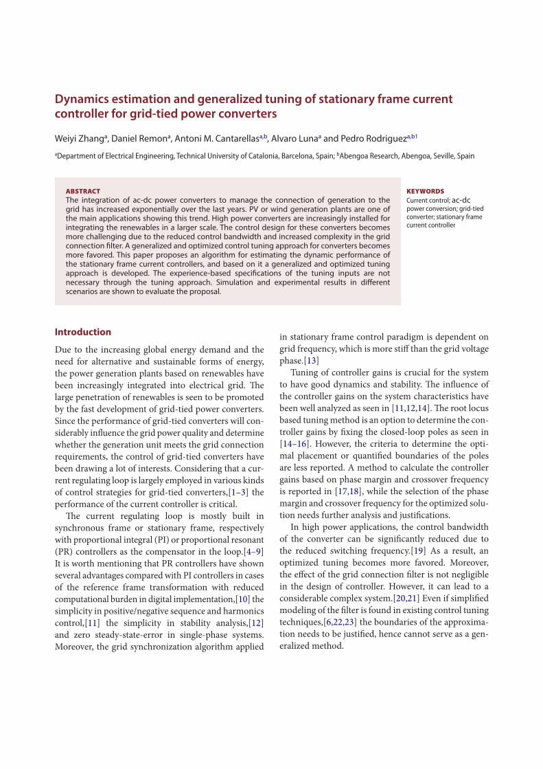
KEYWORDScurrent control; ac-dc power conversion; grid-tied converter; stationary frame current controller
Dynamics estimation and generalized tuning of stationary frame current controller for grid-tied power converters
Weiyi Zhanga, Daniel Remona, Antoni M. Cantarellasa,b, Alvaro Lunaa and Pedro Rodrigueza,b1
adepartment of Electrical Engineering, technical university of catalonia, Barcelona, spain; babengoa research, abengoa, seville, spain
ABSTRACTThe integration of ac-dc power converters to manage the connection of generation to the grid has increased exponentially over the last years. PV or wind generation plants are one of the main applications showing this trend. High power converters are increasingly installed for integrating the renewables in a larger scale. The control design for these converters becomes more challenging due to the reduced control bandwidth and increased complexity in the grid connection filter. A generalized and optimized control tuning approach for converters becomes more favored. This paper proposes an algorithm for estimating the dynamic performance of the stationary frame current controllers, and based on it a generalized and optimized tuning approach is developed. The experience-based specifications of the tuning inputs are not necessary through the tuning approach. Simulation and experimental results in different scenarios are shown to evaluate the proposal.
Introduction
Due to the increasing global energy demand and the need for alternative and sustainable forms of energy, the power generation plants based on renewables have been increasingly integrated into electrical grid. The large penetration of renewables is seen to be promoted by the fast development of grid-tied power converters. Since the performance of grid-tied converters will con-siderably influence the grid power quality and determine whether the generation unit meets the grid connection requirements, the control of grid-tied converters have been drawing a lot of interests. Considering that a cur-rent regulating loop is largely employed in various kinds of control strategies for grid-tied converters,[1–3] the performance of the current controller is critical.
The current regulating loop is mostly built in synchronous frame or stationary frame, respectively with proportional integral (PI) or proportional resonant (PR) controllers as the compensator in the loop.[4–9] It is worth mentioning that PR controllers have shown several advantages compared with PI controllers in cases of the reference frame transformation with reduced computational burden in digital implementation,[10] the simplicity in positive/negative sequence and harmonics control,[11] the simplicity in stability analysis,[12] and zero steady-state-error in single-phase systems. Moreover, the grid synchronization algorithm applied
in stationary frame control paradigm is dependent on grid frequency, which is more stiff than the grid voltage phase.[13]
Tuning of controller gains is crucial for the system to have good dynamics and stability. The influence of the controller gains on the system characteristics have been well analyzed as seen in [11,12,14]. The root locus based tuning method is an option to determine the con-troller gains by fixing the closed-loop poles as seen in [14–16]. However, the criteria to determine the opti-mal placement or quantified boundaries of the poles are less reported. A method to calculate the controller gains based on phase margin and crossover frequency is reported in [17,18], while the selection of the phase margin and crossover frequency for the optimized solu-tion needs further analysis and justifications.
In high power applications, the control bandwidth of the converter can be significantly reduced due to the reduced switching frequency.[19] As a result, an optimized tuning becomes more favored. Moreover, the effect of the grid connection filter is not negligible in the design of controller. However, it can lead to a considerable complex system.[20,21] Even if simplified modeling of the filter is found in existing control tuning techniques,[6,22,23] the boundaries of the approxima-tion needs to be justified, hence cannot serve as a gen-eralized method.
This paper covers two issues in current control design of gird-tied converters, respectively the estimation of system transient response and the optimal placement of the closed-loop poles. Oriented to the first issue, an algo-rithm for estimating the dynamics of a stationary frame current control loop is proposed. And for the second issue, a generalized tuning approach is developed based on a modified PR control structure and the proposed algorithm. The proposed algorithm and generalized tun-ing approach is justified by simulation and experimental results in different scenarios.
The rest of the paper is organized as follows: Firstly, the overall control architecture of the system under study is introduced, followed by the review of discrete-time domain pole placement. Then the dynamics estimation algorithm is proposed, based on which a generalized controller tuning approach is developed, and a tuning case is illustrated. Simulation and experimental results are presented to validate the proposed dynamics estimat-ing algorithm and generalized tuning method, followed by the conclusion of the paper.
Stationary frame current control of grid-tied power converters
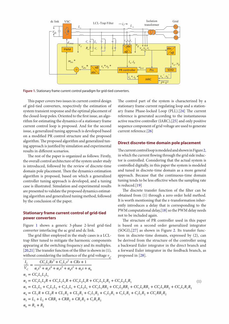
Figure 1 shows a generic 3-phase 2-level grid-tied converter interfacing the ac grid and dc link.
The grid filter employed in the study cases is a LCL-trap filter tuned to mitigate the harmonic components appearing at the switching frequency and its multiples.[20,21] The transfer function of the filter is shown in (1), without considering the influence of the grid voltage vg.
(1)
I2
VC
=CCtLtRs
3 + CtLts2 + CRs + 1
1s5 +
2s4 +
3s3 +
4s2 +
5s +
6
1= CCtL1
L2Lt
2= CCtL1
L2R + CCtL1
LtR + CCtL2LtR + CCtL1
LtR2+ CCtL2
LtR1
3= CL
1L2+ CtL1
L2+ CtL1
Lt + CtL2Lt + CCtL1
RR2+ CCtL2
RR1+ CCtLtRR1
+ CCtLtRR2+ CCtLtR1
R2
4= CL
1R + CL
2R + CL
1R2+ CL
2R1+ CtL1
R2+ CtL2
R1+ CtLtR1
+ CtLtR2+ CCtRR1
R2
5= L
1+ L
2+ CRR
1+ CRR
2+ CR
1R2+ CtR1
R2
6= R
1+ R
2
The control part of the system is characterized by a stationary frame current regulating loop and a station-ary frame Phase-locked Loop (PLL).[24] The current reference is generated according to the instantaneous active reactive controller (IARC),[25] and only positive sequence component of grid voltage are used to generate current reference.[26]
Direct discrete-time domain pole placement
The current control loop is modeled and shown in Figure 2, in which the current flowing through the grid side induc-tor is controlled. Considering that the actual system is controlled digitally, in this paper the system is modeled and tuned in discrete-time domain as a more general approach. Because that the continuous-time domain tuning tends to be less effective when the sampling rate is reduced.[19]
The discrete transfer function of the filter can be obtained from (1) through a zero order hold method. It is worth mentioning that the z-transformation inher-ently introduces a delay that is corresponding to the PWM computational delay,[18] so the PWM delay needs not to be included again.
The structure of PR controller used in this paper is based on a second order generalized integrator (SOGI),[27] as shown in Figure 2. Its transfer func-tion in discrete-time domain, expressed by (2), can be derived from the structure of the controller using a backward Euler integrator in the direct branch and a forward Euler integrator in the feedback branch, as proposed in [28].
Figure 1. stationary frame current control paradigm for grid-tied converters.
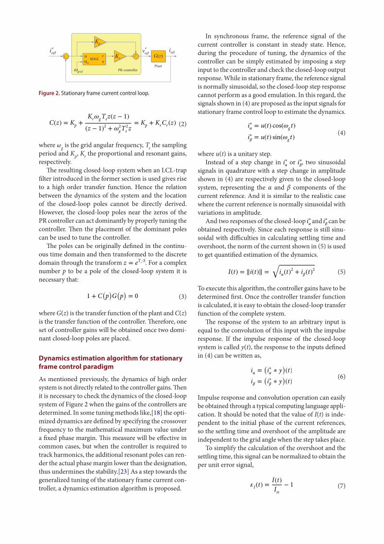
where ωg is the grid angular frequency, Ts the sampling period and Kp, Kr the proportional and resonant gains, respectively.
The resulting closed-loop system when an LCL-trap filter introduced in the former section is used gives rise to a high order transfer function. Hence the relation between the dynamics of the system and the location of the closed-loop poles cannot be directly derived. However, the closed-loop poles near the zeros of the PR controller can act dominantly by properly tuning the controller. Then the placement of the dominant poles can be used to tune the controller.
The poles can be originally defined in the continu-ous time domain and then transformed to the discrete domain through the transform z = eTs⋅S. For a complex number p to be a pole of the closed-loop system it is necessary that:
where G(z) is the transfer function of the plant and C(z) is the transfer function of the controller. Therefore, one set of controller gains will be obtained once two domi-nant closed-loop poles are placed.
Dynamics estimation algorithm for stationary frame control paradigm
As mentioned previously, the dynamics of high order system is not directly related to the controller gains. Then it is necessary to check the dynamics of the closed-loop system of Figure 2 when the gains of the controllers are determined. In some tuning methods like,[18] the opti-mized dynamics are defined by specifying the crossover frequency to the mathematical maximum value under a fixed phase margin. This measure will be effective in common cases, but when the controller is required to track harmonics, the additional resonant poles can ren-der the actual phase margin lower than the designation, thus undermines the stability.[23] As a step towards the generalized tuning of the stationary frame current con-troller, a dynamics estimation algorithm is proposed.
(2)C(z) = Kp +KrgTsz(z − 1)
(z − 1)2+ 2
gT2
s z= Kp + KrCr(z)
(3)1 + C(p)G(p)= 0
In synchronous frame, the reference signal of the current controller is constant in steady state. Hence, during the procedure of tuning, the dynamics of the controller can be simply estimated by imposing a step input to the controller and check the closed-loop output response. While in stationary frame, the reference signal is normally sinusoidal, so the closed-loop step response cannot perform as a good emulation. In this regard, the signals shown in (4) are proposed as the input signals for stationary frame control loop to estimate the dynamics.
where u(t) is a unitary step.Instead of a step change in i∗
or i∗
, two sinusoidal
signals in quadrature with a step change in amplitude shown in (4) are respectively given to the closed-loop system, representing the α and β components of the current reference. And it is similar to the realistic case where the current reference is normally sinusoidal with variations in amplitude.
And two responses of the closed-loop i∗ and i∗
can be
obtained respectively. Since each response is still sinu-soidal with difficulties in calculating settling time and overshoot, the norm of the current shown in (5) is used to get quantified estimation of the dynamics.
To execute this algorithm, the controller gains have to be determined first. Once the controller transfer function is calculated, it is easy to obtain the closed-loop transfer function of the complete system.
The response of the system to an arbitrary input is equal to the convolution of this input with the impulse response. If the impulse response of the closed-loop system is called y(t), the response to the inputs defined in (4) can be written as,
Impulse response and convolution operation can easily be obtained through a typical computing language appli-cation. It should be noted that the value of I(t) is inde-pendent to the initial phase of the current references, so the settling time and overshoot of the amplitude are independent to the grid angle when the step takes place.
To simplify the calculation of the overshoot and the settling time, this signal can be normalized to obtain the per unit error signal,
(4)i∗= u(t) cos(g t)
i∗= u(t) sin(g t)
(5)I(t) = ‖i(t)‖ =
i(t)2 + i
(t)2
(6)i=(i∗∗ y
)(t)
i=(i∗∗ y
)(t)
(7)I(t) =I(t)
Iss− 1
Figure 2. stationary frame current control loop.
yields a scalar equation, whereas a pair of complex poles generates one complex equation, which can be trans-formed to two scalar equations by separating the real and imaginary parts. Calling pr the real pole and pc one of the complex poles, the equations define the following linear system in Kp, Kr and Kq,
In the generalized tuning procedure, two complex poles expressed as −n ± j
√1 − 2n and a real pole
expressed as −cξωn need to be properly placed, and the tuning consists on sweeping a range of values for ωn, ξ and c.
For each set of these three values, the first step is to calculate the corresponding controller gains through (9). The open-loop and the closed-loop transfer functions will be obtained once the controller gains are fixed. The open-loop transfer function can be used to calculate the gain margin and the phase margin. On the other hand, the closed-loop transfer function allows computing the settling time and the overshoot using the proposed algorithm. Besides, the closed-loop transfer function provides information on the poles and the zeros, thus the results obtained for each set of poles allow checking whether all the poles are inside the unit circle. These results can be compared with the control requirements to see if that particular set of poles can be considered an acceptable solution. If this is the case, this set of poles is marked as a candidate.
The search continues until all the values of ωn, ξ and c have been tested. Once it is finished, the candidate solutions are compared among each other to select the most suitable one taking into account the control requirements.
Analytical performance
This tuning procedure can also be applied to tune the original 2-gain PR controller, and only two poles need to be placed instead of 3. Therefore, in this paper the tuning procedure is applied to tune both the original and the generalized PR controller for a 10 kW converter with LCL-trap filter as shown in Figure 1.
To start the algorithm, a wide range of search can be defined, with high discretization step. For instance, solutions can be searched in the range n ∈ 100, 150, 200,… , 1500 rad/s, ∈ 0.05, 0.10, 0.15,… , 0.95 and c ∊ 1, 2, 3, …500. Then it is possible to identify a smaller range where more optimized solutions can be found. This new range can be used in a new search. In this way, successive refined searches can be carried out until the precision and the
(9)
⎛⎜⎜⎜⎜⎝
1 Cr(pr) Cq
pr
1 ReCr
pc
Re
Cq
pc
0 ImCr
pc
Im
Cq
pc
⎞⎟⎟⎟⎟⎠
⎛⎜⎜⎜⎝
Kp
Kr
Kq
⎞⎟⎟⎟⎠= −
⎛⎜⎜⎜⎜⎝
1
G(pr )
Re
1
G(pc)
Im
1
G(pc)
⎞⎟⎟⎟⎟⎠
With this function, the overshoot is maxI = max
tI(t)
and the settling time is ts = mints.t.||𝜀I(s)|| < 𝜀ss∀s > t
,
where εss defines the per unit tolerance band of the steady state.
Generalized tuning approach
The objective of the tuning is to determine the controller gains that can bring about stable and fast current regula-tion. Based on the discrete-time domain pole placement and the dynamics estimation algorithms proposed in the former section, a generalized tuning approach for stationary frame current regulators is illustrated.
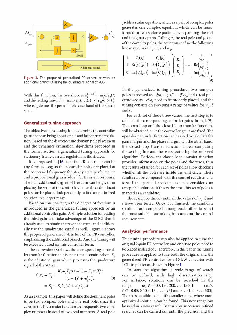
It is proposed in [16] that the PR controller can be any form as long as the controller poles are placed at the concerned frequency for steady state performance and a proportional gain is added for transient response. Then an additional degree of freedom can be given in placing the zeros of the controller, hence three dominant poles can be placed independently to find an optimized solution in a larger range.
Based on this concept, a third degree of freedom is introduced in the generalized tuning approach by an additional controller gain. A simple solution for adding the third gain is to take advantage of the SOGI that is already used to obtain the resonant term, and addition-ally use the quadrature signal as well. Figure 3 shows the proposed generalized structure of the PR controller, emphasizing the additional branch. And the tuning will be executed based on this controller form.
The expression (8) shows the corresponding control-ler transfer function in discrete-time domain, where Kq is the additional gain which processes the quadrature signal of the SOGI.
As an example, this paper will define the dominant poles to be two complex poles and one real pole, since the zeros of the PR transfer function are frequently two com-plex numbers instead of two real numbers. A real pole
(8)C(z) = Kp +
KrgTsz(z − 1) + Kq2
gT2
s z
(z − 1)2+ 2
gT2
s z
= Kp + KrCr(z) + KqCq(z)
Figure 3. the proposed generalized pr controller with an additional branch utilizing the quadrature signal of soGi.
Then the design requirements summarized in Table 1 are used to filter the candidate solutions.
After performing the search, it is possible to deter-mine one solution – among all those considered accept-able – that best fulfils the control objectives. In this case, taking into account that stability is guaranteed by the required gain and phase margins and that the overshoot is limited to avoid damaging or having to oversize the converter, the main objective of the design is set to reduce the settling time. Therefore, the solution with minimum settling time is chosen from the set of all valid solutions. Additionally, in order to break possible ties, a small weighting coefficient has been considered for the overshoot in such a way that, if two solutions result in equal settling times, the solution with lower overshoot is preferred.
In Table 2, the controller parameters and the perfor-mance results are shown for the objective of minimizing the settling time for both controllers. The generalized controller provides an improved solution when com-pared to the original one.
Simulation results
The performance of the proposed dynamics estimation algorithm and the generalized tuning method is firstly validated in simulation tests in 10 and 100 kW systems respectively. Step changes in power reference are given, and the waveforms and data of current, voltage and some intermediate variables are recorded and evalu-ated. A comparison between the generalized tuning and the tuning based on original PR controller is also given.
The simulated plant is built in Simulink environment as shown in Figure 5. The model consists of a 2-level 3-phase converter connected to the grid through the designed filter. The converter is controlled as shown in Figure 1, and it is discretized and coded in the embedded Matlab function block in the simulation. The gains of the controller are adopted according to Table 2.
performance of the solution are adequate. Each time of search can be programmed and run automatically aided by a typical computing language application, since (9) can be easily expressed and calculated in the applica-tion as well as the evaluation of stability and transient response.
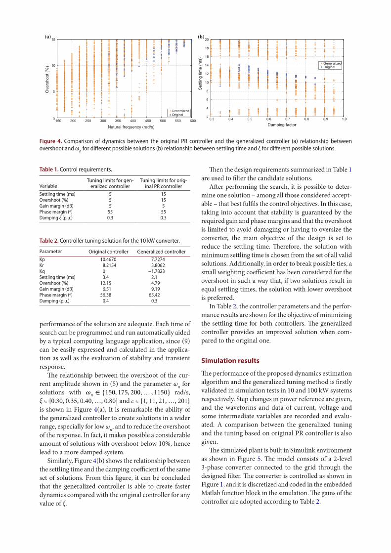
The relationship between the overshoot of the cur-rent amplitude shown in (5) and the parameter ωn for solutions with n ∈ 150, 175, 200,… , 1150 rad/s, ξ ∊ 0.30, 0.35, 0.40, …, 0.80 and c ∊ 1, 11, 21, …, 201 is shown in Figure 4(a). It is remarkable the ability of the generalized controller to create solutions in a wider range, especially for low ωn, and to reduce the overshoot of the response. In fact, it makes possible a considerable amount of solutions with overshoot below 10%, hence lead to a more damped system.
Similarly, Figure 4(b) shows the relationship between the settling time and the damping coefficient of the same set of solutions. From this figure, it can be concluded that the generalized controller is able to create faster dynamics compared with the original controller for any value of ξ.
150 200 250 300 350 400 450 500 550 6000
5
10
15
Ove
rsho
ot (%
)
GeneralizedOriginal
Natural frequency (rad/s)
0.3 0.4 0.5 0.6 0.7 0.8 0.9 1.02
4
6
8
10
12
14
16
18
20
Settl
ing
time
(ms)
GeneralizedOriginal
Damping factor
(a) (b)
Figure 4. comparison of dynamics between the original pr controller and the generalized controller (a) relationship between overshoot and ωn for different possible solutions (b) relationship between settling time and ξ for different possible solutions.
Table 1. control requirements.
VariableTuning limits for gen-
eralized controllerTuning limits for orig-
inal PR controllersettling time (ms) 5 15overshoot (%) 5 15Gain margin (dB) 5 5phase margin (º) 55 55damping ξ (p.u.) 0.3 0.3
Table 2. controller tuning solution for the 10 kw converter.
Parameter Original controller Generalized controllerKp 10.4670 7.7274Kr 8.2154 3.8062Kq 0 −1.7823settling time (ms) 3.4 2.1overshoot (%) 12.15 4.79Gain margin (dB) 6.51 9.19phase margin (º) 56.38 65.42damping (p.u.) 0.4 0.3
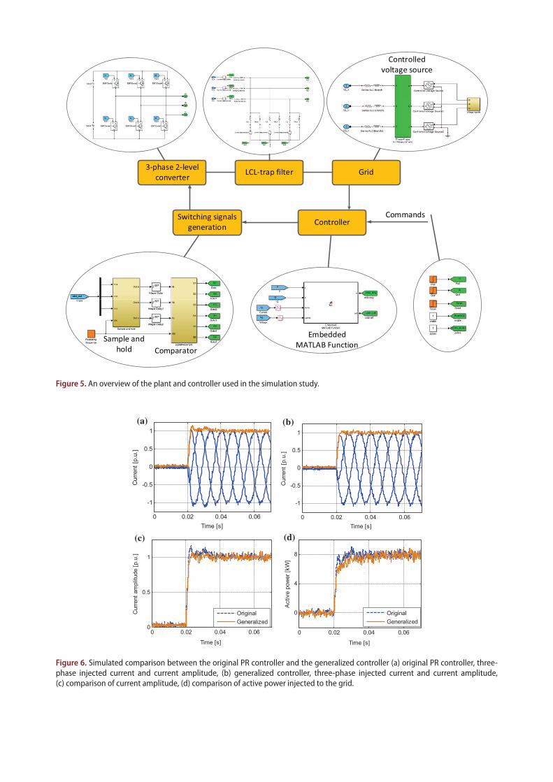
Figure 5. an overview of the plant and controller used in the simulation study.
(a) (b)
(c) (d)
0 0.02 0.04 0.06
-1
-0.5
0
0.5
1
Time [s]
Cur
rent
[p.u
.]
0 0.02 0.04 0.06
-1
-0.5
0
0.5
1
Time [s]
Cur
rent
[p.u
.]
0 0.02 0.04 0.060
0.5
1
Time [s]
Cur
rent
am
plitu
de [p
.u.]
Original Generalized
0 0.02 0.04 0.06
0
4
8
Time [s]
Act
ive
pow
er [k
W]
OriginalGeneralized
Figure 6. simulated comparison between the original pr controller and the generalized controller (a) original pr controller, three-phase injected current and current amplitude, (b) generalized controller, three-phase injected current and current amplitude, (c) comparison of current amplitude, (d) comparison of active power injected to the grid.
controller are compared in Figure 6(d). The resulting settling time of both types of controller has no significant difference, while the resulting overshoot of the gener-alized controller is smaller, which is coherent with the estimation of the proposed algorithm. And the gener-alized controller leads to a more smooth active power transfer during transient.
Experimental results
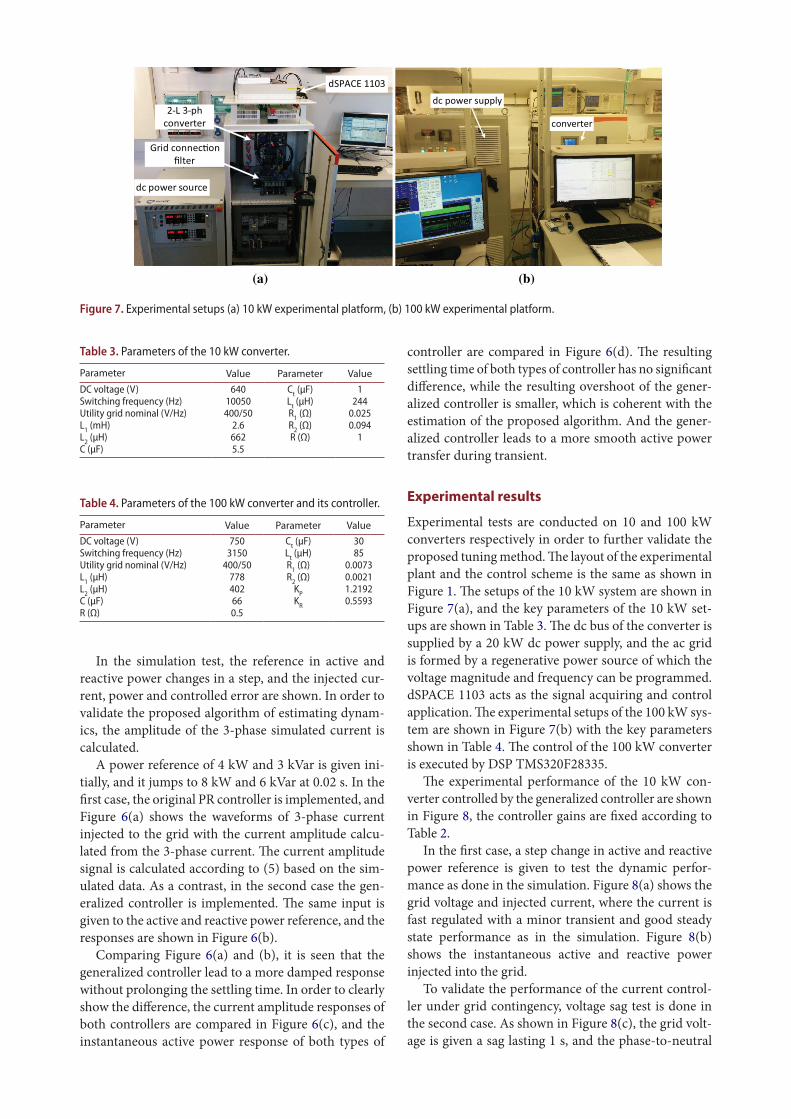
Experimental tests are conducted on 10 and 100 kW converters respectively in order to further validate the proposed tuning method. The layout of the experimental plant and the control scheme is the same as shown in Figure 1. The setups of the 10 kW system are shown in Figure 7(a), and the key parameters of the 10 kW set-ups are shown in Table 3. The dc bus of the converter is supplied by a 20 kW dc power supply, and the ac grid is formed by a regenerative power source of which the voltage magnitude and frequency can be programmed. dSPACE 1103 acts as the signal acquiring and control application. The experimental setups of the 100 kW sys-tem are shown in Figure 7(b) with the key parameters shown in Table 4. The control of the 100 kW converter is executed by DSP TMS320F28335.
The experimental performance of the 10 kW con-verter controlled by the generalized controller are shown in Figure 8, the controller gains are fixed according to Table 2.
In the first case, a step change in active and reactive power reference is given to test the dynamic perfor-mance as done in the simulation. Figure 8(a) shows the grid voltage and injected current, where the current is fast regulated with a minor transient and good steady state performance as in the simulation. Figure 8(b) shows the instantaneous active and reactive power injected into the grid.
To validate the performance of the current control-ler under grid contingency, voltage sag test is done in the second case. As shown in Figure 8(c), the grid volt-age is given a sag lasting 1 s, and the phase-to-neutral
In the simulation test, the reference in active and reactive power changes in a step, and the injected cur-rent, power and controlled error are shown. In order to validate the proposed algorithm of estimating dynam-ics, the amplitude of the 3-phase simulated current is calculated.
A power reference of 4 kW and 3 kVar is given ini-tially, and it jumps to 8 kW and 6 kVar at 0.02 s. In the first case, the original PR controller is implemented, and Figure 6(a) shows the waveforms of 3-phase current injected to the grid with the current amplitude calcu-lated from the 3-phase current. The current amplitude signal is calculated according to (5) based on the sim-ulated data. As a contrast, in the second case the gen-eralized controller is implemented. The same input is given to the active and reactive power reference, and the responses are shown in Figure 6(b).
Comparing Figure 6(a) and (b), it is seen that the generalized controller lead to a more damped response without prolonging the settling time. In order to clearly show the difference, the current amplitude responses of both controllers are compared in Figure 6(c), and the instantaneous active power response of both types of
(a) (b)
Figure 7. Experimental setups (a) 10 kw experimental platform, (b) 100 kw experimental platform.
Table 3. parameters of the 10 kw converter.
Parameter Value Parameter Valuedc voltage (v) 640 ct (μF) 1switching frequency (Hz) 10050 lt (μH) 244utility grid nominal (v/Hz) 400/50 r1 (Ω) 0.025l1 (mH) 2.6 r2 (Ω) 0.094l2 (μH) 662 r (Ω) 1c (μF) 5.5
Table 4. parameters of the 100 kw converter and its controller.
Parameter Value Parameter Valuedc voltage (v) 750 ct (μF) 30switching frequency (Hz) 3150 lt (μH) 85utility grid nominal (v/Hz) 400/50 r1 (Ω) 0.0073l1 (μH) 778 r2 (Ω) 0.0021l2 (μH) 402 Kp 1.2192c (μF) 66 Kr 0.5593r (Ω) 0.5
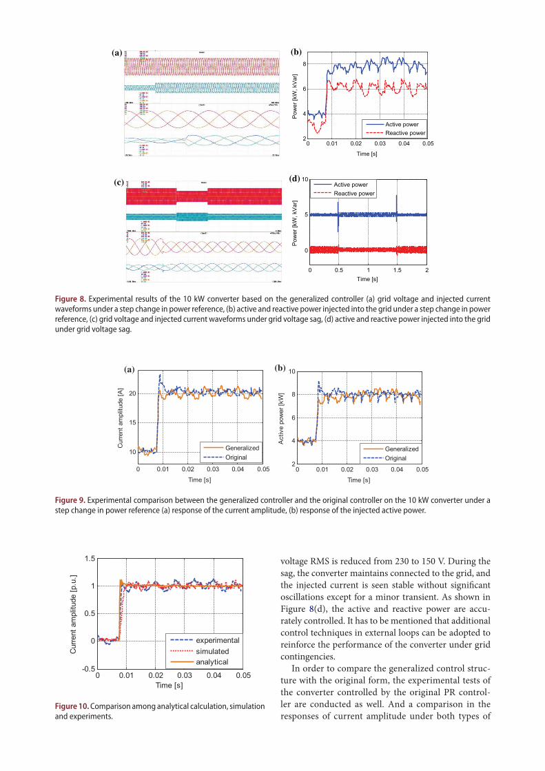
voltage RMS is reduced from 230 to 150 V. During the sag, the converter maintains connected to the grid, and the injected current is seen stable without significant oscillations except for a minor transient. As shown in Figure 8(d), the active and reactive power are accu-rately controlled. It has to be mentioned that additional control techniques in external loops can be adopted to reinforce the performance of the converter under grid contingencies.
In order to compare the generalized control struc-ture with the original form, the experimental tests of the converter controlled by the original PR control-ler are conducted as well. And a comparison in the responses of current amplitude under both types of
(a) (b)
(c) (d)
0 0.01 0.02 0.03 0.04 0.052
4
6
8
Time [s]
Pow
er [k
W, k
Var]
Active powerReactive power
0 0.5 1 1.5 2
0
5
10
Time [s]
Pow
er [k
W, k
Var]
Active powerReactive power
Figure 8. Experimental results of the 10 kw converter based on the generalized controller (a) grid voltage and injected current waveforms under a step change in power reference, (b) active and reactive power injected into the grid under a step change in power reference, (c) grid voltage and injected current waveforms under grid voltage sag, (d) active and reactive power injected into the grid under grid voltage sag.
(a) (b)
0 0.01 0.02 0.03 0.04 0.05
10
15
20
Time [s]
Cur
rent
am
plitu
de [A
]
GeneralizedOriginal
0 0.01 0.02 0.03 0.04 0.052
4
6
8
10
Time [s]
Act
ive
pow
er [k
W]
GeneralizedOriginal
Figure 9. Experimental comparison between the generalized controller and the original controller on the 10 kw converter under a step change in power reference (a) response of the current amplitude, (b) response of the injected active power.
0 0.01 0.02 0.03 0.04 0.05-0.5
0
0.5
1
1.5
Time [s]
Cur
rent
am
plitu
de [p
.u.]
experimentalsimulatedanalytical
Figure 10. comparison among analytical calculation, simulation and experiments.
The paper can be a reference in tuning of stationary frame current controllers for grid-tied power convert-ers considering the below aspects. The reduced control bandwidth and increased filter complexity in high power applications requires a more optimized tuning with respect to dynamics. The generalized tuning approach developed in the paper can be applied in different scenarios.
Disclosure statementNo potential conflict of interest was reported by the authors.
FundingThis work has been partially supported by the Spanish Ministry of Economy and Competitiveness under the project ENE2014-60228-R. Any opinions, findings and conclusions or recommendations expressed in this material are those of the authors and do not necessarily reflect those of the host institutions or funders.
Notes on contributorsWeiyi Zhang received the B. Eng. in Electrical Engineering and M.Sc. in Power Electronics and Electrical Drive from the Northwestern Polytechnical University, Xi’an, China, in 2010 and 2013, respectively. He has been working towards the Ph.D. degree at research center on Renewable Electrical Energy Systems (SEER) in
Technical University of Catalonia, Spain since 2013. His cur-rent research interests include control of power converters and integration of distributed generation systems.
Daniel Remon received the degree in Electrical Engineering and the degree in Mathematics from the Technical University of Catalonia (UPC), Barcelona, Spain, in 2012, and the M.Sc. degree in Electrical Energy Systems from the University of Seville, Seville, Spain, in 2015. He is cur-rently working toward the PhD degree in
Electrical Energy Systems at the UPC. He has worked for Abengoa, Seville, Spain, as an industrial PhD fellow in
controllers under step changes in power reference is shown in Figure 9(a), while a comparison in the responses of active power is shown in Figure 9(b). The current amplitude signal is calculated according to (5) based on the sensed current. As shown in the figure, a more damped performance of the proposed general-ized controller is again verified.
Figure 10 shows the responses of the current ampli-tude by analytical calculation, simulation and experi-ments. The analytical calculation is obtained based on the modeling of the closed loop. The simulation and experimental responses are respectively obtained in sim-ulation and experimental tests by giving a step change in power reference.
As shown in Figure 10, the proposed dynamics esti-mating algorithm can act as an indicator of the system dynamics due to the similar behavior compared to the simulation and experimental results.
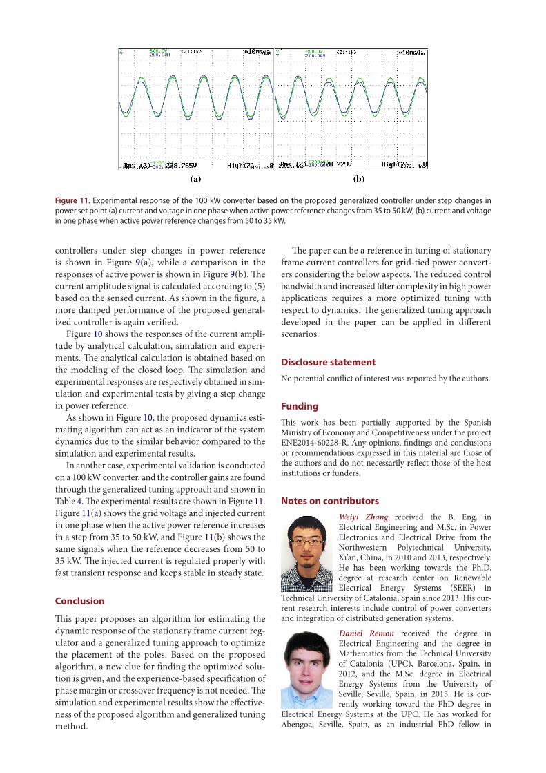
In another case, experimental validation is conducted on a 100 kW converter, and the controller gains are found through the generalized tuning approach and shown in Table 4. The experimental results are shown in Figure 11. Figure 11(a) shows the grid voltage and injected current in one phase when the active power reference increases in a step from 35 to 50 kW, and Figure 11(b) shows the same signals when the reference decreases from 50 to 35 kW. The injected current is regulated properly with fast transient response and keeps stable in steady state.
Conclusion
This paper proposes an algorithm for estimating the dynamic response of the stationary frame current reg-ulator and a generalized tuning approach to optimize the placement of the poles. Based on the proposed algorithm, a new clue for finding the optimized solu-tion is given, and the experience-based specification of phase margin or crossover frequency is not needed. The simulation and experimental results show the effective-ness of the proposed algorithm and generalized tuning method.
Figure 11. Experimental response of the 100 kw converter based on the proposed generalized controller under step changes in power set point (a) current and voltage in one phase when active power reference changes from 35 to 50 kw, (b) current and voltage in one phase when active power reference changes from 50 to 35 kw.
[2] Ochoa-Gimenez M, Roldan-Perez J, Garcia-Cerrada A, et al. Space-vector-based controller for current-harmonic suppression with a shunt active power filter. In: Proc. EPE; Lille; 2013. p. 1–10.
[3] Egea-Alvarez A, Junyent-Ferre A, Gomis-Bellmunt O, et al. Operation and control of VSC-HVDC multiterminal grids for offshore wind. EPE J. 2013;23:34–39.
[4] Fukuda S, Yoda T. A novel current-tracking method for active filters based on a sinusoidal internal model. IEEE Trans Ind Appl. 2001;37:888–895.
[5] Gabe IJ, Montagner VF, Pinheiro H. Design and implementation of a robust current controller for VSI connected to the grid through an LCL filter. IEEE Trans Power Electron. 2009;24:1444–1452.
[6] Park SY, Chen CL, Lai JS, et al. Admittance compensation in current loop control for a grid-tie LCL fuel cell inverter. IEEE Trans Power Electron. 2008;23:1716–1723.
[7] Zmood DN, Holmes DG. Stationary frame current regulation of PWM inverters with zero steady-state error. IEEE Trans Power Electron. 2003;18:814–822.
[8] Rouzbehi K, Miranian A, Luna A, et al. Optimized control of multi-terminal DC grids using particle swarm optimization. EPE J. 2014;24:38–49.
[9] Rocabert J, Azevedo GMS, Candela I, et al, Connection and disconnection transients for micro-grids under unbalance load condition. In: Proc. EPE; Birmingham; 2011. p. 1–9.
[10] Teodorescu R, Blaabjerg F, Liserre M, et al. Proportional-resonant controllers and filters for grid-connected voltage-source converters. Electric Power Appli IEE Proc. 2006;153:750–762.
[11] Yuan X, Merk W, Stemmler H, et al. Stationary-frame generalized integrators for current control of active power filters with zero steady-state error for current harmonics of concern under unbalanced and distorted operating conditions. IEEE Trans Ind Appl. 2002;38:523–532.
[12] Twining E, Holmes DG. Grid current regulation of a three-phase voltage source inverter with an LCL input filter. IEEE Trans Power Electron. 2003;18:888–895.
[13] Rodríguez P, Luna A, Candela I, et al. Multiresonant frequency-locked loop for grid synchronization of power converters under distorted grid conditions. IEEE Trans Ind Electron. 2011;58:127–138.
[14] Li B, Yao W, Hang L, et al. Robust proportional resonant regulator for grid-connected voltage source inverter (VSI) using direct pole placement design method. IET Power Electron. 2012;5:1367–1373.
[15] Zeng G, Rasmussen TW. Design of current-controller with PR-regulator for LCL-filter based grid-connected converter. PEDG. 2010;2010:490–494.
[16] Lezana P, Silva CA, Rodríguez J, et al. Zero- steady-state-error input-current controller for regener-ative multilevel converters based on single-phase cells. IEEE Trans Ind Electron. 2007;54:733–740.
[17] Buso S, Mattavelli P. Digital control in power electronics 1st ed. Vol. 1, No. 1. Morgan & Claypool: USA; 2006.
[18] Holmes DG, Lipo TA, McGrath BP, et al. Optimized design of stationary frame three phase AC current regulators. IEEE Trans Power Electron. 2009;24:2417–2426.
[19] Turner R, Walton S, Duke R. Robust high-performance inverter control using discrete direct-design pole placement. IEEE Trans Ind Electron. 2011;58:348–357.
[20] Cantarellas AM, Rakhshani E, Remon D, et al. Design of the LCL+trap filter for the two-level VSC installed in a large-scale wave power plant. In: ECCE; Denver; 2013. p. 707–712.
2013–2015, and has been a visiting student at the University of Waterloo, Ontario, Canada, in 2015–2016, with a ‘la Caixa’ grant. His current research interests include renewable energy integration in transmission and distribution systems, power system modeling, stability and control, and electricity markets.
Antoni M. Cantarellas received the B.Sc. degree in electrical engineering from the Technical University of Catalonia (UPC), Barcelona, Spain, and the M.Sc. degree in wind power systems from Aalborg University, Aalborg, Denmark, in 2010 and 2012 respectively. He is currently pursuing the Ph.D. degree from the UPC. In 2012, he
joined Abengoa Research, Abengoa, Seville, where he is cur-rently a PhD fellow in the area of distributed generation. His current research interests include distributed generation and control of power plants.
Alvaro Luna received the B.Sc., M.Sc., and Ph.D. degrees from the Technical University of Catalonia (UPC), Barcelona, Spain, in 2001, 2005, and 2009, respectively, all in electrical engineering. He joined as a Faculty Member at UPC in 2005, where he is cur-rently an Assistant Professor. His research interests include wind turbines control, PV
systems, integration of distributed generation, and power conditioning.
Pedro Rodriguez received the M.Sc. and Ph.D. degrees in electrical engineering from the Technical University of Catalonia (UPC), Spain, in 1994 and 2004, respectively. He was a Postdoctoral Researcher at the Center for Power Electronics Systems (CPES), Virginia Tech, Blacksburg in 2005, and at the Department of Energy Technology, Aalborg
University (AAU) in 2006. He joined the faculty of UPC as an Assistant Professor in 1990, where he became the Director of the research center on Renewable Electrical Energy Systems (SEER) in the Department of Electrical Engineering. He was also a Visiting Professor at the AAU from 2007 to 2011, acting as a co-supervisor of the Vestas Power Program. He still lec-tures Ph.D. courses at the AAU every year. From 2011, he is the Head of Electrical Engineering division in Abengoa Research, although he is still joined to the UPC as a part time Professor. He has coauthored one book and more than 100 papers in technical journals and conference proceedings. He is the holder of seven licensed patents. His research interests include integration of distributed generation systems, smart grids, and design and control of power converters. Dr. Rodriguez is a Fellow of the IEEE, a member of the adminis-trate committee of the IEEE Industrial Electronics Society (IES), the general chair of IEEE-IES Gold and Student Activities, the vice-chair of the Sustainability and Renewable Energy Committee of the IEEE Industry Application Society and a member of the IEEE-IES Technical Committee on Renewable Energy Systems. He is an Associate Editor of the IEEE Transaction on Power Electronics.
References [1] Vasquez JC, Guerrero JM, Savaghebi M, et al.
Modeling, analysis, and design of parallel three-phase voltage source inverters. IEEE Trans Ind Electron. 2013;60:1271–1280.

systems during grid faults. IEEE Trans Ind Electron. 2007;54:2583–2592.
[26] Rodríguez P, Luna A, Ciobotaru M, et al. Advanced grid synchronization system for power converters under unbalanced and distorted operating conditions. In: Proc. IECON; Paris; 2006. p. 5173–5178.
[27] Rodriguez P, Teodorescu R, Candela I, et al. New positive-sequence voltage detector for grid synchronization of power converters under faulty grid conditions. In: 37th IEEE Power Electronics Specialists Conference; Jeju; 2006. p. 1–7.
[28] Rodríguez FJ, Bueno E, Aredes M, et al. Discrete-time implementation of second order generalized integrators for grid converters. In: Proceedings – 34th Annual Conference of the IEEE Industrial Electronics Society, IECON 2008; Orlando; 2008. p. 176–181.
[21] Xu J, Yang J, Ye J, et al. An LTCL filter for three-phase grid-connected converters. IEEE Trans Power Electron. 2014;29:4322–4338.
[22] Espi JM, Castello J, García-Gil R, et al. An adaptive robust predictive current control for three-phase grid-connected inverters. IEEE Trans Ind Electron. 2011;58:3537–3546.
[23] Yepes AG, Freijedo FD, López Ó, et al. Analysis and design of resonant current controllers for voltage-source converters by means of nyquist diagrams and sensitivity function. IEEE Trans Ind Electron. 2011;58:5231–5250.
[24] Rodríguez P, Luna A, Muñoz-Aguilar RS, et al. A stationary reference frame grid synchronization system for three-phase grid-connected power converters under adverse grid conditions. IEEE Trans Power Electron. 2012;27:99–112.
[25] Rodriguez P, Timbus AV, Teodorescu R, et al. Flexible active power control of distributed power generation


![Generalized PIO Design for Uncertain Discrete Time Systems · stationary parameters [19]. The LPV systems are a generalization of LTV systems, establishing an inter-mediate model](https://img.pdfslide.us/doc/110x75/5f5fdddfaf8f7b2578568649/generalized-pio-design-for-uncertain-discrete-time-stationary-parameters-19-the.jpg)