Embed Size (px)
Citation preview
Dynamical stable cavity of side-pumpedthin-disk laser with slanted sides
Hamed Aminpour,1,* Mustafa Yadegari,1,2 Mashaiekhy Asl,1
and Jamshid Sabbaghzadeh1
1Iranian National Center of Laser Science and Technology (INCLST), P.O. Box 14665-567, Tehran, Iran([email protected])
2Department of Physics, University of Guilan, P.O. Box 41335-19141, Rasht, Iran
*Corresponding author: [email protected]
Received 7 September 2010; revised 9 November 2010; accepted 26 November 2010;posted 13 January 2011 (Doc. ID 134307); published 11 February 2011
In this article, we use the results of finite-element analysis (FEA) of temperature distribution, deforma-tion, and stress to provide a full three-dimensional simulation of a dynamically stable cavity by propa-gating wavefront into hot, thermally deformed Yb:YAG/YAG thin-disk laser, using the fast Fouriertransform (FFT) split-step beam propagation method (BPM). The wave optics computation thereforedelivers realistic results for important features of a laser-like intensity, phase profile, and resonatoreigenvalues and higher order-eigenmodes of the laser beam. © 2011 Optical Society of AmericaOCIS codes: 140.3580, 140.3615, 140.3410.
1. Introduction
Dynamically stable resonators are well suited to re-duce the influence of internal lenses [1–4]. Dynami-cally stable means that the radius of the laser modein the active medium passes an extremum, depend-ing on the refractive power of an internal thermallens [5–7]. The design of the laser resonator (com-prising optical elements, angles of incidence, anddistances between the components) determines thebeam radius of the fundamental mode at all locationsalong the beam, together with other important prop-erties. For maximum beam quality, the beam radiusin the gain medium has to approximately match theradius of the pumped region. For smaller beam radii,operation with multiple spatial modes is obtained,leading to a nonideal beam quality; however, suchmultimode lasers have other advantages such asmuch wider stability zones and a lower sensitivityto misalignment. Particularly for high-power laserswith good beam quality, thermal lensing in the gainmedium is very important. The resonator design
should be made so that changes of the thermal lensdo not affect the mode sizes too much. Also, it shouldhave a low sensitivity to thermal aberrations andmisalignment [8,9]. The importance of these factorsshould not be underestimated; there are cases wheretwo resonators, even with equal mode sizes in thegain medium, lead to very different laser perfor-mance and are radically different in terms ofalignment.
Focusability of laser beam to small spots withoutdivergence is a fundamental property of the outputlight emerging from a laser cavity. This so-calledbeam quality factor is important in many laser appli-cations [10] and can be defined as the ratio of thebeam standard deviation to that of a Gaussian beam[11]. The knowledge of the beam propagation factoris sufficient to characterize the beam quality of thelaser. Once the beam quality (M2) is measured forthe laser beam, the beam quality is well defined, nomatter what kind of optics are used for beam trans-formation and focusing [12,13]. Light rays thatbounce back and forth between the spherical mirrorsof a laser resonator experience a periodic focusingaction. Rays passing through a stable sequence oflenses are periodically refocused. For unstable
0003-6935/11/060811-11$15.00/0© 2011 Optical Society of America
20 February 2011 / Vol. 50, No. 6 / APPLIED OPTICS 811

systems, the rays become more and more dispersedthe further they passed through the sequence. In anoptical resonator operated in the stable region, thewaves propagate between reflectors without spread-ing appreciably [14,15].
A beam with M2 > 1 can be a coherent higher-order mode, or a superposition of several modes withdifferent frequencies. A coherent mode with M2 > 1can, in principle, be converted into a fundamentalmode by a suitable phase plate, as was shown theo-retically and experimentally [16–18], whereas asuperposition of modes cannot.
Generally, thin-disk lasers are introduced to over-come laser material issues and to improve someparameters, such as heat transfer in laser material.End-pump laser systems require complex pumpingequipment to achieve multipass [19] pumping. Thismultipass technique is essential to obtain an efficientabsorption length. In edge-pumped thin-disk lasers,efficient absorption length is achieved, eliminatingthe need for complicated pumping setups [20], andpumping can be done by simply focusing the diodelight to the active media or use of some alternativelens and hollow ducts [21–23].
Edge-pumped thin-disk lasers assure efficient ab-sorption length and simple pump configurationbriefly speaking, pump beam shaping is explicit [24].Different output powers and crystal structures suchas microchip composite [25] and ceramic microchip[26] lasers have been reported for efficient edgepumped thin-disk lasers. In Ref. [26], Taira andhis coworkers used a square composite microchip, inwhich an undoped YAG layer surrounded the corematerial that was used as a waveguide to transmitthe optical pump light to the core active media. Inthis paper, we introduce a new geometry with an un-doped cap layer that is bonded to the top of activemedia. Total internal reflection (TIR) routinely takesplace with the pumping arrangement that is used inour model [27]; there is no need for a coated surface,to reflect pump wavelength, on the internal face ofupper surface of the disk.
In this study, we present results obtained from aspecific thin-disk with a dynamically stable resona-tor. Thermomechanical computations of disk such
as stress and optical path difference (OPD) as wellas numerical simulations of the field distributionin the resonator are performed. On the basis of thesestudies, in the following sections, we describe the im-plementation of thin-disk laser with dynamicallystable resonator.
2. Thermo-Optical Modeling
A diagram of the calculation algorithm of the thindisk that was performed with respect to the beamquality factorM2. The pump light distribution, whichwas obtained by the ray tracing method, is depictedin Fig. 1. Absorbed pump power, temperature distri-bution, stress components, and deformation in thegain medium are calculated by using finite-elementanalysis (FEA).
On the basis of these results, several thermo-optical effects such as OPD and refractive power ofthin disk are also considered. Thermal lensing andmechanical distortions can affect the beam qualityof lasers. Usually one is interested in the sensitivityof the resonator to thermal lensing effects, whichlead mainly to a change in mode size and beam diver-gence. For optimization of the beam quality, the em-phasis is often placed on minimizing the intracavitydistortions, e.g., by creating a smooth pump intensitydistribution and using a laser crystal with a high-power efficiency and good thermal conductivity (seeRef. [9]).
In this work, model parameters are obtained fromour previous paper [27]. A thin disk with slantededges and slanted sides is pumped with a maximumpump power Pp ¼ 2kW by use of four stacked diodelasers set at 941nm. Top view of thin-disk activemedia is a 8mm × 8mm square and thickness of0:2mm. Its edges are cut at 30° with respect to thefloor and Yb/YAG active medium is bonded on a1:3mm thick YAG top layer to act as a covering cap,to reduce ASE effect and deformation. Dopant con-centration of disk is 14%.
The basic principle of the side-pumped thin-disk la-ser is illustrated inFig. 2.Related to the specific struc-ture of the gain medium, we have done geometricaloptics calculations and applied them using the ray-tracingmethod,basedonthe twogoals ofhomogeneity
Fig. 1. (Color online) Diagram of the calculation algorithm.
812 APPLIED OPTICS / Vol. 50, No. 6 / 20 February 2011

and uniformity of pump light distribution. Theabsorbed pump-power distribution is determined byusing FEA. The pump light has a Gaussian spectraldistribution. The pump-light irradiance profile is de-picted in Fig. 3. In order to identify the influences ofthe results on the beam quality in combination withthermomechanical computations, theOPD of the diskare analyzed. The temperature and stress distribu-tion obtained by FEA can be used in two differentprocedures:
• Optical path difference (OPD)• Physical optics propagation code
Based on these studies, the refractive power andoptical path difference of the thin disk are calculated,the laser resonator is designed, and concepts forcompensating the OPD are developed.
A. Refractive Power of Thin Disk
All laser media can be described in a first approachas a thick lens due to a refractive power induced bythe pumping process. The shift sensitivity of the la-ser beam is equal to the variation of dioptric power ofthe output beam. In order to get a small shift of thefocus, a resonator setup providing a low shift sensi-tivity must be found [28,29]. In order to adapt thestability range of the resonator to the variation of theradius of curvature of the disk, the refractive powerof the disk was measured as a function of the pumppower in multimode operation. The maximum pump-power range Pp;max for stable laser oscillation is givenas [30,31]
ΔPp;max ¼ð2M2 − 1Þ4λ
D� ; ð1Þ
where M2 is the beam propagation factor, λ denotesthe wavelength, D� ¼ D
IPumpis the specific refractive
power (dioptric power) caused by pump intensity I,and D ¼ f −1 ¼ dn
dT2KðTÞAPheat is the focal power of thethermal lens of the laser [32]. The specific dioptric
Fig. 2. (Color online) Geometry of the model.
Fig. 3. (Color online) Pump light distribution.
20 February 2011 / Vol. 50, No. 6 / APPLIED OPTICS 813

power D� has to be reduced to make possible the useof higher pump powers while retaining good beamquality. It is essential to achieving good thin-disklaser performance to reduce thermal and stress-induced lensing and make the effective D� smaller.The refractive power D of the thin disk shows anearly linear decrease with respect to the pumppower Pp. This linear tendency is in accordance withpredictions of thermo-mechanical computations(See [30]). The typical reduction of the refractivepower is 7 ∼ 15 cm−1 for a pump power up to 2kW. Asdepicted in Fig. 4 at maximum pump power, the re-fractive power of the disk is between 0:93m−1 and0:99m−1. Comparing the refractive powers along thex and y axes, there is also a slight astigmatism.
The differences of these refractive powers are about4% of the maximum value. For designing the resona-tor, the minimum refractive power, i.e., maximumfocal length of the disk at maximum pump power,was taken as an upper limit of the thermal lens.
B. Optical Path Difference (OPD)
The quantum defect in fluorescence processes, stimu-lated emission as well as amplified spontaneousemission (ASE) processes, yields an increase of thetemperature of the disk with increasing pump power.The resulting increase in the refractive index, thethermal expansion as well as the deformation of thedisk, has the same importance as the variation ofthe OPD which is important for the field distributionin the resonator [33]. The change of the refractive in-dex can be caused by temperature and a stress-dependent variation. By using the results of FEA,the OPD is calculated, considering the deformationof the HR end of the thin disk. The change of thick-ness due to thermal expansion, and the change of therefractive index due to temperature and stress, aredepicted in Fig. 5.
OPD ¼ 2 ×�Z
dCrystal
0
∂n∂T
ðTðr; yÞ − T0Þ½1þ εyðr; yÞ�dy
þZ
dCrystal
0Δnsðr; yÞ½1þ εyðr; yÞ�dy
þZ
dCrystal
0Δ½n0 − 1�εyðr; yÞdy − y0ðrÞ
�; ð2Þ
here n0 is the refractive index at the reference tem-perature T0, dn
dT is the thermo-optical coefficient, Δnsis the change of refractive index due to strain, εy isthe strain in the y direction, and y0 is the displace-ment of the HR end of the disk. The terms in Eq. (2)show the temperature gradient, strain-induced bire-fringence, axial strain gradient (bulging), and defor-mation effects, respectively. In order to developconcepts for the compensation of phase distortionsas well as for an improvement of alternative designsof disk bonding, OPD measurements have been per-formed. The total OPD of a thin disk can be consid-ered as a sum of a parabolic part and a remainingnonparabolic part. Deviations of the OPD from theideal parabolic shape cause phase distortions ofthe field distribution. The parabolic part of the OPDcan be simply compensated by a variation of the re-sonator parameters, e.g., varying the radius of curva-ture of a mirror or varying the resonator length.
3. Thin-Disk Laser with Dynamically Stable Resonator
As shown in the previous section, thermal lensing inthin-disk lasers is not negligible in the high-powerregime. Therefore, a thin-disk laser resonator can beconsidered as a resonator containing an internal fo-cusing element. However, for fundamental modeoperation, the radius of the laser mode has to beadapted to the radius of the pump spot, and the re-sonator should be almost insensitive against thermallensing. Dynamically stable resonators can combinethese two features, simultaneously. A dynamicallystable resonator is a special type of stable resonator
Fig. 4. (Color online) Refractive power of the disk as a function ofthe pump power.
Fig. 5. (Color online) Optical path difference due to thermalgradient, stress, and displacement.
814 APPLIED OPTICS / Vol. 50, No. 6 / 20 February 2011

that contains one internal lens between the two lasermirrors. Usually, dynamically stable resonators havetwo ranges of stability. Each range has a point of in-sensitivity of the mode radius to the variation of therefractive power of the internal lens.
In the first step of these calculations, one canacquire the effect of path differences on electricfield distribution, which appear as optical phasedistortions, ΦðrÞ, as in
ΦðrÞ ¼ 2πλ OPD; ð3Þ
where λ is the laser wavelength. To discuss the opti-cal phase distortion effects on resonator perfor-mance, we suppose a Gaussian fundamental modewith mode radius ω and no curvature resonates inthe resonator. The electric field of this mode canbe written as
EnormalizedðrÞ ¼ exp�−r2
ω2 þ iΦ�; ð4Þ
where ω is the mode radius and Φ is the phase of theelectric field. Asmentioned above, the thermo-opticaleffects on the disk impose a phase shift to the electricfield given by Eq. (3) after each pass through the thindisk
EnormalizedðrÞ ¼ exp�−r2
ω2 þ iðΦ −ΦðrÞÞ�: ð5Þ
For convenience, the optical phase distortion in thethin disk can be separated into a spherical and anaspherical part as follows:
ΦðrÞ ¼ 2πr2λRL
−ΔΦðrÞ: ð6Þ
After some manipulations, the electric field distribu-tion is finally given as
EnormalizedðrÞ ¼ exp�−r2
ω2 þ iΦ − i2πr2λRL
þ iΔΦðrÞ�:
ð7ÞProjection on a set of Gauss–Laguerre modes withsuitable curvature RL gives
C00 ¼Z Z
EnormalizedE00rdrΨ
¼ 2πZ
exp½iΔΦðrÞ� exp�−r2
ω2
�dr: ð8Þ
Defining LB ≡ 1 − jC00j2 as the diffraction loss of thefundamental mode, one can look for a value of RL(giving the focal length f L ¼ RL
2 ) that minimizes thediffraction loss and the remaining aspherical phasedistortion. The spherical part of the optical phasedistortion can be easily compensated in the resonatordesign.
A. Stable Laser Resonator Modeling
In a stable resonator, the thermal lensing does notinfluence the structure of the modes, but its dimen-sions and mode order can be influenced, because theradius ω depends on the refractive power. The num-ber of transverse modes m, which is equal to thebeam propagation factor M2, is given by the ratioof disk radius R to mode radius ω [34]:
M2 ≡m ¼ Rω ð9Þ
The stability of a resonator can be expressed by a sta-bility criterion. The mode size and position are sen-sitive to optomechanical perturbations of the opticalelements. In the design of the resonator, for an opti-mummode size, it will be of the utmost importance toconsider the resonator sensitivity to these mechani-cal effects [35].
At low pumping levels, the mode radius is largeand only a few modes will oscillate. With increasingpower, the thermal lens reduces the mode radius andmore modes oscillate. At very high pumping levels,the lens will focus the radiation, and on the mirrors,a tiny spot appear. The divergence of the radiation ishigh, the beam radius in the active medium is large,and again, only a fewmodes will oscillate. This multi-mode operation of thin-disk resonator is unavoidablein a high-power regime. To lessen these effects, weuse an internal aperture with radius of 4mm withinthe cavity (Fig. 6). For a resonator with length L ¼0:4m and the curvature of spherical mirror R2 ¼1m, one can obtain the beam spot size on the output
coupler mirror. ω22 ¼ λ
πR2
ffiffiffiffiffiffiffiffiffiL
R2−L
q, which is 475 μm for
TEM00, and is 1062 μm for TEM22 by consideringinitial spot size on the rear mirror ω2
0 ≡ ω21 ¼
λπ
ffiffiffiffiffiffiffiffiffiffiffiffiffiffiffiffiffiffiffiffiffiLðR2 − LÞp
which is 364 μm for TEM00 and is814 μm for TEM22.
Fig. 6. (Color online) Dynamically stable linear resonator withone thin-disk as plano-concave mirror (L ¼ 40 cm); mirror radii,R1 ¼ ∞, R2 ¼ 1m, curvature radius of the disk Rdisk ¼ ½0:94m;
0:99m�; calculated beam radius of TEM00 on the mirrors; outputcoupler reflectivity Rf ¼ 96%).
20 February 2011 / Vol. 50, No. 6 / APPLIED OPTICS 815

As a result, we could demonstrate multimode op-eration of a dynamically stable resonator with onedisk, with a maximum output power Pout ¼ 616W(pump power PP ¼ 2KW) and an optical efficiencyηOptical ¼ 0:34. Figure 7 shows the stability diagramof a thin-disk laser resonator and a schematic of thebeam radius and spot sizes.
1. Analytical Method to Determine the Number ofRound-Trips in the Cavity
Consider a resonator with a round trip (see Fig. 6).The ray matrix will be given by MN to reproduceany input ray; we need to determine the numberof round trips to make the identity matrix, orMN ¼ 1
�A BC D
�¼ MN ¼ I ¼
�1 00 1
�: ð10Þ
This can be determined numerically, but can be alsobe addressed using eigenvalue analysis. The ap-proach is to obtain an equation for N assuming aPlano-concave resonator with length L and the endmirror radius of curvature 2f
MNνi ¼ λNνi;
MN ¼ λNM ¼�1 L
0 1
�� 1 0
− 1f 1
��1 L
0 1
�⇒ M
¼� 1 − L
f 2L − L2
f
− 1f 1 − L
f
�: ð11Þ
Using this equation, one can obtain a relation for Nas follows:
Let X ≡ 1 − Lf ; then λ ¼ X �
ffiffiffiffiffiffiffiffiffiffiffiffiffiffiffiffi1 − X2j
pis the matrix
eigenvalue and can be presented as λ ¼ expðjϕÞ,ϕ ¼ tan−1ð
ffiffiffiffiffiffiffiffiffi1−X2
pX Þ, λN ¼ expðjNϕÞ, and finally
N ¼ 2kπΦ ¼ 2kπ
tan−1
� ffiffiffiffiffiffiffiffiffi1−X2
pX
� : ð12Þ
A ray launched parallel to the optical axis will oscil-late back and forth across the resonator cavity. Para-meters used for round-trip analytical calculations oflaser cavity are listed in Table 1. It is assumed thatthe beam coming from the diode is propagating like aGaussian beam in a plane perpendicular to the slowaxis. The FWHM of the diodes is used to compute theGaussian far-field angle in this plane, which is de-fined as the angle where the intensity drops to 1
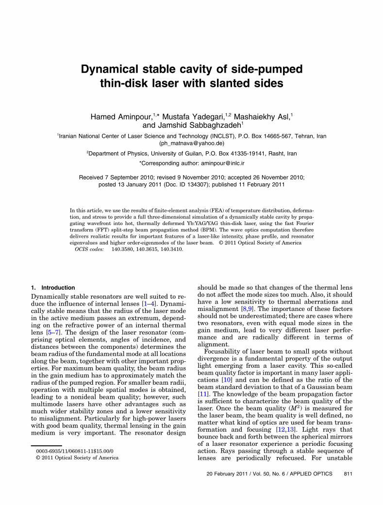
e.The results of analytical calculation of beam radius
versus round trips in the laser stable cavity is illu-strated in Fig. 8. From this figure, one can see thatafter long iterations (2050), the FWHM is about200 μm.
2. Converged Resonator Field Due to InternalAperture
In the special but significant case that the beam ispropagating through spherical or more specifically,parabolic, dielectric interfaces, Gaussian ducts, i.e.,parabolic distributions of refractive index and gain,or is reflected on spherical mirrors, analytical solu-tions of the paraxial wave equation are availablein the form of the well known Hermite–Gaussianpolynomials. In real situations, the Gaussian mode
Fig. 7. (Color online) Top: TEM00 mode radius for Plano-concaveresonator. Bottom: g-parameter (stability) diagram of laser resona-tor. Computations are carried through simultaneously in twoplanes perpendicular to the resonator axis. The lower point indi-cated with þ symbol is the g parameter in x direction, upper pointis that in y direction.
Table 1. Parameters Used for Round Trip Analytical Calculationsof Laser Cavity
Parameter Value Unit
Rc (radius of output coupler) 1 mCavity length 0.4 mPropagation grid 256 by 56 μmWavelength 1.03 μmOutput mirror reflectivity 96 %Initial field BWomika Top hat field of (4) mmNormalization 1 –
Round trip 2050 –
Aperture diameter 4 mmaA plane wave with random phase that tends to seed all modes of
the resonator.
816 APPLIED OPTICS / Vol. 50, No. 6 / 20 February 2011
algorithm can successfully be applied, if the distribu-tions of refractive index and gain in laser crystals canbe approximated by parabolic fits. There are, how-ever, situations where the Gaussian mode algorithmis not sufficient, and therefore a full numerical ana-lysis is needed. For this purpose, since the early workof Fox and Li [36], instead of the partial differentialequation (PDE), an equivalent integral equation tra-ditionally is involved, based on the so-called round-trip condition [37,38]. This means that a propagationintegral acts on a wavefront at a certain referenceplane to produce a new optical field describing thewavefront at the same reference plane, but afterone round trip through the cavity representing an ei-genmode, the recirculated wavefront must meet theeigenvalue equation.
By defining a mode as an electromagnetic wavewhose electric field can be written as EðrÞ and repre-sent a Fredholm homogeneous integral equation ofthe second kind, its eigensolutions give the field dis-tribution over the mirror aperture for cavity modes[39]
γnmEnmðx:yÞ ¼Z Z
Kðx; y; x0; y0ÞEnmðx0; y0Þdx0dy0;ð13Þ
where the K of the propagation operator dependson the properties of the cavity, and is a complexeigenvalue.
The eigenvalues are seen to be such that theirnorm (jγnmj2) gives the factor by which beam inten-sity is changed as a result of one round trip. This
change is due to diffraction losses, thus
1 − jγnmj2 ð14Þgives the round-trip fractional power loss due to dif-fraction. Equation (12) lends itself to try a solution byan iterative application of the integral operator, anapproach that has been used in many modificationssince the pioneering work of Fox and Li [36,37]. Abeam propagation method (BPM) (see [28]) is usedto compute a series of round trips starting with amore or less arbitrary initial field distribution.
The iteratively recirculated field distributionfinally converges to the lowest-order mode or to asuperposition of higher-order transversal modes, de-pendent on the losses of the later ones. The intensityprofile at the output mirror develops with the in-creasing number of iterations, following the profileof Fig. 8, and the beam converges after some itera-tions, here by 78) to its value with the minimumfluctuations (spot size spot size ¼ 972:2 μm). Thisconvergence approach is shown in Fig. 9.
B. The Beam Propagation Method
The BPM allows computation of electromagneticfield propagation through a step-by-step recalcula-tion of the transverse distribution of both the ampli-tude and phase of the optical field [40]. The fielddistribution in any transverse plane depends onlyon this distribution in the previous plane and localcharacteristics of the material. When the mediumis thin so that diffraction inside the gain medium canbe neglected and themedium is pumped so that thereis gain the beam propagation equation becomes [41]
Fig. 8. (Color online) 1=e beam radius on the right mirror is plotted as function of the cavity iteration.
20 February 2011 / Vol. 50, No. 6 / APPLIED OPTICS 817

dIðx; y; zÞdz
¼ gðx; y; zÞ:Iðx; y; zÞ: ð15Þ
Here Iðx; y; zÞ is the laser intensity and gðx; y; zÞ is thegain coefficient at spatial position ðx; y; zÞ. Equa-tion (12) can be solved numerically, although in manycases it can also be solved analytically. When diffrac-tion cannot be ignored, Eq. (12) must be solvednumerically by taking into account the relevant ma-terial parameters. Applying the paraxial and slowlyvarying envelope approximations in the coordinatesystem moving with the light, we find:
2iK∂ε∂z
¼ ∇2Vertical þ ½K2
0ΨNL þ iK20ΨL
N �; ð16Þ
whereΨLN is the imaginary part of the linear suscept-
ibility of the material, ΨNL is the nonlinear suscept-ibility of the material, K is the wavenumber in thematerial, and K0 is the wavenumber in vacuum.
For cases where parabolic approximation andABCD Gaussian propagation code are not sufficient,FEA results alternatively can be used as input for aphysical optics code that uses a fast Fourier trans-form (FFT) split-step BPM. Using a FFT BPM to pro-pagate the wavefront in small steps through thecrystal takes into account the distribution of the re-fractive index, as well as the deformed end faces ofthe crystal, as obtained by FEA. A series of roundtrips through the resonator is computed, which final-ly converges to the fundamental or to a superpositionof higher-order transversal modes. The data dis-played in Fourier space intensity is used to calculatethe beam quality M2 in both x and y directions(Fig. 10).
Fig. 9. (Color online) Convergence of spot size versus cavity iteration.
Fig. 10. (Color online) Fourier space intensity, where the beamintensity on the right mirror is displayed in Fourier space.
818 APPLIED OPTICS / Vol. 50, No. 6 / 20 February 2011

4. Laser Beam Diameter and Determining the M2
Factor
A monochromatic beam with a beam propagationfactor of M2 ¼ 1 is a TEM00 Gaussian beam and isalways coherent (see Sec 3).
The transverse intensity profile for a Gaussianbeam in TEM00 mode is given in one transversecoordinate, by
Iðx; yÞ ¼ I0 exp�−2x2
ω2ðxÞ�; ð17Þ
where I0 is the intensity on (r ¼ 0, y ¼ 0) and ωðyÞ isthe Gaussian spot size radius on the y axis. However,many lasers produce beams that comprise modes ofhigher order than TEM00 mode. To measure the laserbeam waist dimension, we supposed that the beam isclose to a Gaussian beam [similar to Eq. (16)]. We de-termined the beam quality factor (M2 factor) by as-suming that the spot size propagation formula foran arbitrary ideal beam, based on the spatial-variance definition of spot size, is given by Eq. (17).
ωðyÞ ¼ ω0
ffiffiffiffiffiffiffiffiffiffiffiffiffiffiffiffiffiffiffiffiffiffiffiffiffiffiffiffiffiffiffiffiffiffiffiffiffiffiffi1þ
�M2λðy − y0Þ
nπω20
�s2
; ð18Þ
where ω0 is the minimumGaussian beam spot size atdistance y0 (here,ω0 is located on the rearmirror),n isthe refraction index of the medium, and λ is thewavelength. This factor measures the relative far-field spreading of a real laser beamrelative to an idealGaussian TEM00 mode beam. Intensity in differentiteration steps and phase of the wave inmaximum in-tensity are shown in Figs. 11 and 12 respectively. Thisinformationmay then be compared directly with phy-sical wavefront measurements and provide impor-tant information about beam quality.
It is clear that after some iteration (say, 80 itera-tion steps in this calculation) the system reaches itsequilibrium state. The maximum cw output power in
Fig. 11. (Color online) Three-dimensional shape of the intensityon the outcoupling mirror due to the cavity iterations in A, 10; B,50; and C, 80.
Fig. 12. (Color online) Phase of the wave on the right mirror atthe point of maximum intensity.
20 February 2011 / Vol. 50, No. 6 / APPLIED OPTICS 819
multimode operation is 616W (pump power is 2kW)and the optical efficiency is η ¼ 34% with a para-meter M2 that is less than 40 and the laser spot sizeon output coupler mirror ω0 of approximately 364 μm
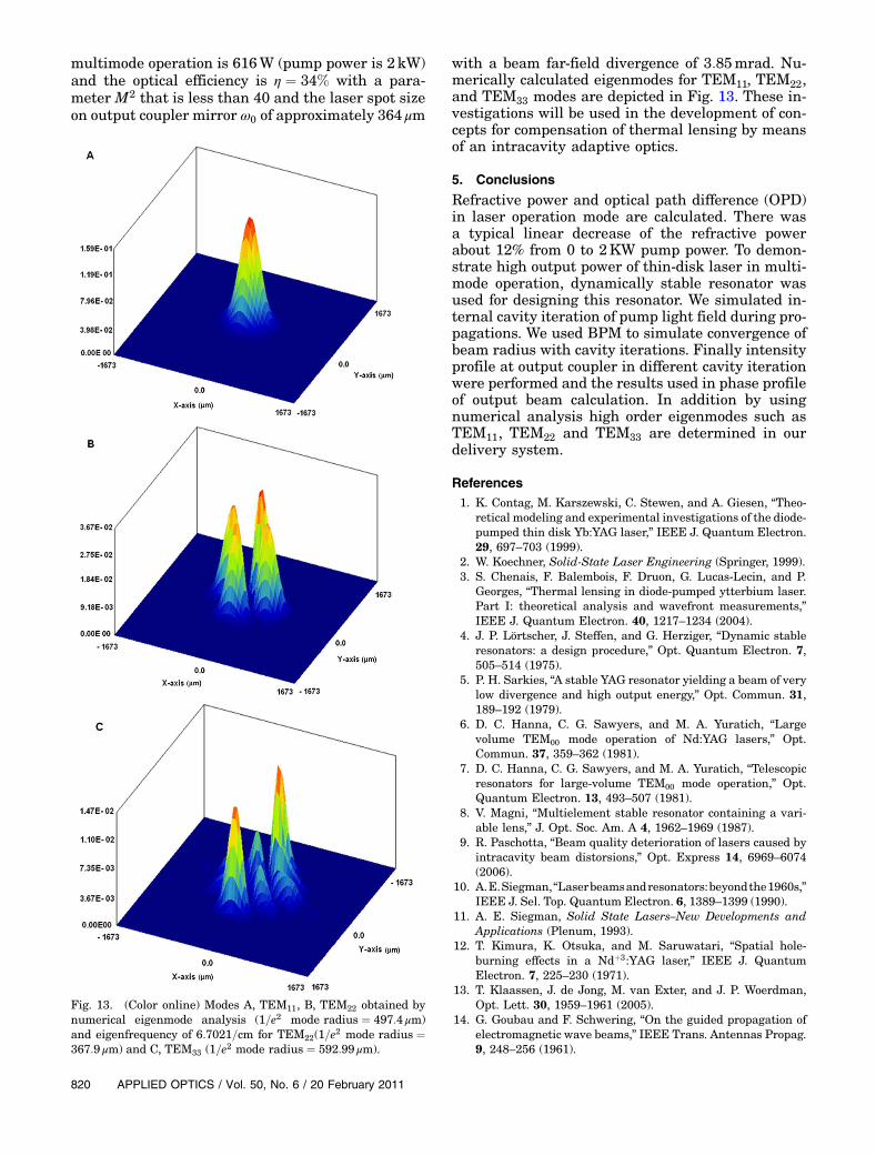
with a beam far-field divergence of 3:85mrad. Nu-merically calculated eigenmodes for TEM11, TEM22,and TEM33 modes are depicted in Fig. 13. These in-vestigations will be used in the development of con-cepts for compensation of thermal lensing by meansof an intracavity adaptive optics.
5. Conclusions
Refractive power and optical path difference (OPD)in laser operation mode are calculated. There wasa typical linear decrease of the refractive powerabout 12% from 0 to 2KW pump power. To demon-strate high output power of thin-disk laser in multi-mode operation, dynamically stable resonator wasused for designing this resonator. We simulated in-ternal cavity iteration of pump light field during pro-pagations. We used BPM to simulate convergence ofbeam radius with cavity iterations. Finally intensityprofile at output coupler in different cavity iterationwere performed and the results used in phase profileof output beam calculation. In addition by usingnumerical analysis high order eigenmodes such asTEM11, TEM22 and TEM33 are determined in ourdelivery system.
References1. K. Contag, M. Karszewski, C. Stewen, and A. Giesen, “Theo-
retical modeling and experimental investigations of the diode-pumped thin disk Yb:YAG laser,” IEEE J. Quantum Electron.29, 697–703 (1999).
2. W. Koechner, Solid-State Laser Engineering (Springer, 1999).3. S. Chenais, F. Balembois, F. Druon, G. Lucas-Lecin, and P.
Georges, “Thermal lensing in diode-pumped ytterbium laser.Part I: theoretical analysis and wavefront measurements,”IEEE J. Quantum Electron. 40, 1217–1234 (2004).
4. J. P. Lörtscher, J. Steffen, and G. Herziger, “Dynamic stableresonators: a design procedure,” Opt. Quantum Electron. 7,505–514 (1975).
5. P. H. Sarkies, “A stable YAG resonator yielding a beam of verylow divergence and high output energy,” Opt. Commun. 31,189–192 (1979).
6. D. C. Hanna, C. G. Sawyers, and M. A. Yuratich, “Largevolume TEM00 mode operation of Nd:YAG lasers,” Opt.Commun. 37, 359–362 (1981).
7. D. C. Hanna, C. G. Sawyers, and M. A. Yuratich, “Telescopicresonators for large-volume TEM00 mode operation,” Opt.Quantum Electron. 13, 493–507 (1981).
8. V. Magni, “Multielement stable resonator containing a vari-able lens,” J. Opt. Soc. Am. A 4, 1962–1969 (1987).
9. R. Paschotta, “Beam quality deterioration of lasers caused byintracavity beam distorsions,” Opt. Express 14, 6969–6074(2006).
10. A.E.Siegman,“Laserbeamsandresonators:beyondthe1960s,”IEEE J. Sel. Top. Quantum Electron. 6, 1389–1399 (1990).
11. A. E. Siegman, Solid State Lasers–New Developments andApplications (Plenum, 1993).
12. T. Kimura, K. Otsuka, and M. Saruwatari, “Spatial hole-burning effects in a Ndþ3:YAG laser,” IEEE J. QuantumElectron. 7, 225–230 (1971).
13. T. Klaassen, J. de Jong, M. van Exter, and J. P. Woerdman,Opt. Lett. 30, 1959–1961 (2005).
14. G. Goubau and F. Schwering, “On the guided propagation ofelectromagnetic wave beams,” IEEE Trans. Antennas Propag.9, 248–256 (1961).
Fig. 13. (Color online) Modes A, TEM11, B, TEM22 obtained bynumerical eigenmode analysis (1=e2 mode radius ¼ 497:4 μm)and eigenfrequency of 6:7021=cm for TEM22(1=e2 mode radius ¼367:9 μm) and C, TEM33 (1=e2 mode radius ¼ 592:99 μm).
820 APPLIED OPTICS / Vol. 50, No. 6 / 20 February 2011

15. J. R. Pierce, “Modes in sequences of lenses,” Proc. Natl. Acad.Sci. U.S.A. 47, 1808–1813 (1961).
16. T. Graf and J. E. Balmer, “Laser beam quality, entropy and thelimits of beam shaping,” Opt. Commun. 131, 77–83 (1996).
17. R. Oron, N. Davidson, A. A. Freisen, and E. Hasman, “Contin-uous-phase elements can improve laser beam quality,” Opt.Lett. 25, 939–941 (2000).
18. G.Machavariani,N.Davidson,A.A.Ishaaya,andA.A.Friesem,“Improving the stability of longitudinal and transverse lasermodes,” Opt. Commun. 239, 147–151 (2004).
19. A. Giesen, H. Hugel, A. Voss, K. Wittig, U. Brauch, and H.Opower, “Scalable concept for diode-pumped high-powersolid-state lasers,” Appl. Phys. B 58, 365–372 (1994).
20. T. Dascalu, N. Pavel, and T. Taira, “90W continuous-wavediode edge-pumped microchip composite Yb:Y3Al5O12 laser,”Appl. Phys. Lett. 83, 4086–4088 (2003).
21. R. Fu, G. Wang, E. Ba, G. Mu, and X. Hu, “Design of efficientlens ducts,” Appl. Opt. 37, 4000–4003 (1998).
22. R. J. Beach, “CW theory of quasithree level end-pumped laseroscillators,” Opt. Commun. 123, 385–393 (1996).
23. M. Eichhorn, “Theory and optimization of lens ducts,” Appl.Opt. 47, 1740–1744 (2008).
24. T. Dascalu and T. Taira, “Highly efficient pumping configura-tion for microchip solid-state laser,” Opt. Express 14, 670–677(2006).
25. D. Kracht, D. Freiburg, R. Wilhelm, M. Frede, and C. Fallnich,“Core-doped ceramic Nd:YAG laser,” Opt. Express 14, 2690–2692 (2006).
26. M. Tsunekane and T. Taira, “High-power operation of diodeedge-pumped composite all-ceramic Yb : Y3Al5O12 microchiplaser,” Appl. Phys. Lett. 90, 121101–121103 (2007).
27. H. Aminpour, I. M. Asl, J. Sabbaghzadeh, and K.Kazemi, “Simulation and design of applied hollow-duct usedfor side-pumped cutting-edged of high power disk laser,” Opt.Commun. 283, 4727–4732 (2010).
28. N. Hodgson and H. Weber, Laser Resonator and BeamPropagation (Springer, 2005), Chap. 13.
29. J. Mende, E. Schmid, J. Speiser, G. Spindler, and A. Giesen,“Thin-disk laser—Power scaling to the kW regime infundamental mode operation,” Proc. SPIE 7193, 71931V1(2009).
30. A. Giesen and J. Speiser, “Fifteen years of work on thin-disklasers: results and scaling laws,” IEEE J. Sel. Top. QuantumElectron. 13, 598–609 (2007).
31. T. Graf, E. Wyss, and H. P. Weber, “Thermal lensing of edge-pumped slab lasers I,” Proc. ASSL 50, 688–692 (2001).
32. M. Karszewski, S. Erhard, A. Giesen, and T. Rupp, “Efficienthigh-power TEM00 mode operation of diode-pumped Yb:YAGthin disk lasers,” in Advanced Solid State Lasers (OpticalSociety of America, 2000), paper WE4.
33. C. Pfistner, R. Weber, H. P. Weber, S. Merazzi, and R. Gruber,“Thermal beam distortions in end-pumped Nd:YAG,Nd:GSGG, and Nd:YLF rods,” IEEE J. Quantum Electron.30, 1605–1615 (1994).
34. H. Weber, “Resonators for high power solid state lasers thefight for beam-quality,” Proc. SPIE 3267, 2–13 (1998).
35. H. Kogelnik, “Imaging of optical modes-resonators withinternal lenses,” Bell Syst. Tech. J. 44, 455–494 (1965).
36. A. G. Fox and T. Li, “Resonant modes in a maser interferom-eter,” Bell. Syst. Tech. J 40, 453–458 (1961).
37. Q. Zhang, B. Ozygus, and H. Weber, “Degeneration effectsin laser cavities,” Eur. Phys. J. Appl. Phys. 6, 293–298(1999).
38. V. Magni, “Resonators for solid-state laser with large-volumefundamental mode and high alignment stability,” Appl. Opt.25, 107–117 (1986).
39. O. Svelto and D. C. Hanna, Principles of Lasers (Springer,1998).
40. C. Stewen, K. Contag, M. Larionov, A. Giesen, and H. Hugel,“1kW CW thin disk laser,” IEEE J. Sel. Top. QuantumElectron. 6, 650–657 (2000).
41. T. Y. Fan, “Optimizing the efficiency and stored energy inquasi-three-level lasers,” IEEE J. Quantum Electron. 28,2692–2697 (1992).
20 February 2011 / Vol. 50, No. 6 / APPLIED OPTICS 821