Embed Size (px)
Citation preview
DYNAMICAL MODELS OF CRANIAL KINESIS
by
STEPHANIE S, MILLER, B,A,
A THESIS
IN
MATHEMATICS
Submitted to the Graduate Faculty
of Texas Tech University in Partial Fulfillment of the Requirements for
the Degree of
MASTER OF SCIENCE
A6Drov6d
May, 2002

ACKNOWLEDGEMENTS
I would like to thank Edward Swim for his help in the early stages of this project.
I wouki like to thank my friends and family for their constant encouragement and
support, 1 would like to thank my conmhttee for the time they spent helping me,
including the data given by Dr, Sankar Chatterjee and the program given to me by
Or, Alan Barhorst, And finally I would like to thank everyone who was there when
I nectled to talk.
11
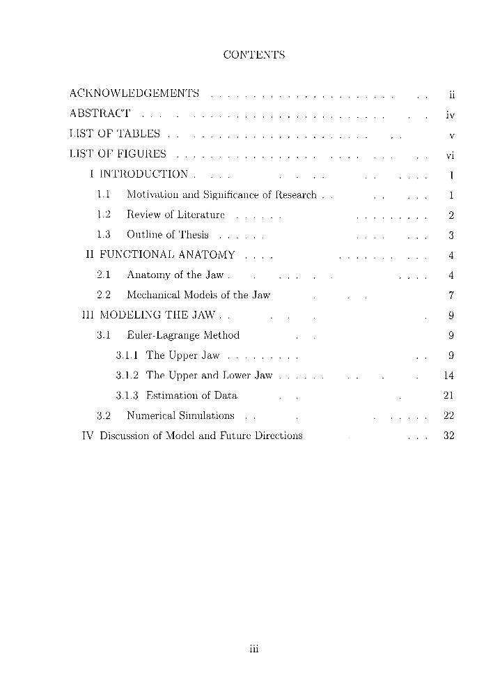
CONTENTS
ACKNOWLEDGEMENTS ii
ABSTRACT iv
LIST OF TABLES v
LIST OF FIGURES vi
I INTRODUCTION , , , , , , , , 1
1.1 Motivation and Significance of Research . , , , , , , 1
1.2 Review of Literature 2
1.3 Outline of Thesis 3
II FUNCTIONAL ANATOMY , , , . 4
2.1 Anatomy of the Jaw , , , , , , 4
2.2 Mechanical Models of the Jaw , , , 7
III MODELING THE JAW . , , , . , 9
3.1 Euler-Lagrange Method , , 9
3.1.1 The Upper Jaw , , 9
3.1.2 The Upper and Lower Jaw . , , . 14
3.1.3 Estimation of Data , , , 2 1
3.2 Numerical Simulations , , , 22
IV Discussion of Model and Future Directions , , , 32
111
ABSTRACT
This work is concerned with the modeling of the movement of the upper or lower
jaw of a bird with res|)ect to the brain case. This functional property is known as
cranial kinesis.
The skeletal t-lenients of the jaw are modeled as a system of articulating rigid finks
and elastic striu'tiu-es. The Euler-Lagrange equations of motion for the joint angles
arc deru'cd while accounting for external inputs that correspond to applied torques
at selected nodes. Computer algebra manipulations are utilized to derive the state
ecjuations, and numerical solutions are computed. Simulations are carried out in order
to illustrate the effects of various system parameters that correspond to variations in
anatomical structure.
IV

LIST OF TABLES
3.1 Data h)r Part 1 26
3.2 Data for Simulations Part 2 27
3.3 Data for Simulations Part 3 28
3.4 Data for Full Beak Simulation 28
LIST OF FIGURES
2.1 Lateral View of Ldrii.s (Herring Gull) Skull Showing Schizoihinal Ex
ternal Naris 5
2.2 Lateral View of Aquila (Golden Eagle) Skull Showing Holorhinal Ex
ternal Naris , , . . , , , , , , 6
2.3 Biomechanical Representation of the Avian Skull , , 7
2.4 Rigid Link and Spring Model of the Jaw , , , , 8
3.1 Lateral View of Larus (Herring Gull) Skufi with Overlay of Links 21
3.2 Lateral View of Aquila (Golden Eagle) Skull with Overlay of Links , , 22
3.3 Lateral View of Ramphastos (Toucan) SkuU 23
3.4 Lateral View of Ramphastos (Toucan) SkuU with Overlay of Links , , 24
3.5 Simulation of Upper Beak of the Larus (Herring Gull) Skull 25
3.6 Simulation of Upper Beak of the Aquila (Golden Eagle) Skull , , , , 29
3.7 Simulation of the Upper Beak the Ramphastos (Toucan) Skull , . 30
3.8 Simulation of Upper and Lower Beak of the Aquila (Golden Eagle) , , 31
VI
CHAPTER I
INTRODUCTION
Mathematical models are used in a variety of disciplines, from the sciences to eco
nomics. These models have been used to examine conjectures, to reduce dependence
on expensive laboratory experiments, to predict future events, to infer data about
past occurrences, and compute optimal behaviors. The ability to build sophisticated
mathematical models has been an unarguable factor in technological developments.
The \'alue of good mathematical models has long been recognized in physical sci
ences. There is, however, a more recent acceptance of the modeling approach to the
life sciences. In this study, a somewhat novel utilization of mathematical modeling is
implemented in order to gain insight into the form and function of the avian skull. It
is hoped that the methodology here will provide not only the ability to simulate the
dynamics of jaw movement, but insight into the evolution of this system.
In recent years, there has been an increasing amount of scientific collaboration
related to the modeling of physiological systems. The work of this thesis utilizes ap
proaches that have been employed in previous research [[5], [6], [7]] that has focused on
the analysis of human movement in order to elucidate the connection between neural
control, biomechanical structure, and attendant consequences in skeletal structures.
Many of the same mathematical tools that developed in that work will be brought
to bear upon analysis of the biomechanics of the bird skull in order to elucidate
connections between form and function,
1,1 Motivation and Significance of Research
Modern biomechanics has been used to model both human and animal movement
systems. In modeling these systems, information regarding optimal movements with
regard to range of motion and forces and work generated can be determined. The
analysis here provides a method for assessing how physiological variations of the jaw
affect the gape, speed of movement, and the magnitude of forces generated b}' the
1

jaw.
An important but secondary intent of this thesis is to develop a framework that
provides a method for relating biomechanical function to evolutionary history. Evo-
lutionar>' studies related to extinct and hving species is a topic of much research in
paleontology and biology. The ability to analyze the biomechanical behavior and
movements of extinct s])ecies might allow paleontologist to hypothesize the causes of
extinction. For instance, the shape and structure of the upper beak has been related
to the feeding habits [11] and heme sucli variations may lead to inferences about the
success and failure of species. It is also important to note that the fossils of some
dinosaurs are similar to that of current avian structures. It has been suggested in [11]
that a biomechanical analysis s of the bird jaw may provide insight into the behavior
of dinosaurs and connect their evolutionary history to current avian species,
1,2 Review of Literature
A few models and studies of the biomechanics of cranial kinesis have been ad
dressed in the literature (see for example [3, 11, 10, 9] and references therein). From
a mechanical point of view, these models are simplistic in nature.
In Chatterjee [3], a lever analysis of the jaw is discussed. This analysis explains
how variations in jaws affect its lever classification. This study does not address the
dynamical properties of the jaw. The mechanical function of the jaw is also addressed
by Zusi [11], This work describes the variations among species and the anatomical
relevance of each of these possible variations on the beak without addressing the
imphcations on the movement of the jaw. In Witmer and Rose [10], a static analysis
of jaw forces is presented. This study relates simple variations in the lever system to
forces generated by the jaw, A three-dimensional model of the jaw is presented in
Van Gennip and Berkhoudt [9], This model uses a kinematic approach, predicting
motion of the jaw without accounting for the inertial properties associated with this
movement.
The main objective of this study is to provide a dynamic model of the jaw that
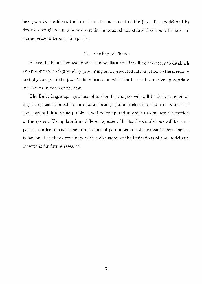
inct)rporates the forces that result in the movement of the jaw. The model wiU be
fiexible enough to incorporate cert,ain anatomical variations that could be used to
charac'terize differences in species.
1,3 Outline of Thesis
Before the biomechanical models can be discussed, it will be necessary to establish
an appropriatt' background by presenting an abbreviated introduction to the anatomy
and physiology of tlu' jaw. This information will then be used to derive appropriate
mechanical models of the jaw.
The Euler-Lagrange equations of motion for the jaw will will be derived by view
ing the s}'stem as a collection of articulating rigid and elastic structures. Numerical
solutions of initial value problems will be computed in order to simulate the motion
in the system. Using data from different species of birds, the simulations will be com
pared in order to assess the implications of parameters on the system's physiological
behavior. The thesis concludes with a discussion of the limitations of the model and
directions for future research.

CHAPTER II
FUNCTIONAL ANATOMY
The anatomy of the jaw of avian differs from the jaw of most animals in that it
allows for a greater range of movements. In particular, modern birds have the ability
tt) mow the upper jaw with resjject to the brain case, referred to as cranial kinesis.
Therefore, to motivate the mechanical model, a brief description of its anatomy is
presented,
2,1 Anatomy of the Jaw
The individual bones of the avian skull are fused in early stages of development,
therefore it is difficult to descriminate the individual bones. Yet, it is possible to
divide horizontally into an upper and lower section. The lower section (referred to
as the lower jaw) consists of only one functional unit, the mandible. The articular
bone of the mandible is rotated to the quadrate of the skull at a ball and socket joint
permitting opening and closing of the jaws (which acts as a pin-joint in the planar
model that is considered here). The upper section consists of four units: the upper
jaw, the jugal bar and pterygiod-palentine bar, the quadrate, and the braincase. The
skull consists of a dorsal bar, two lateral bars, two ventral bars, a symphysis, and a
naris, but in the two-dimensions considered in this study, only one lateral and one
ventral bar are present. The symphysis is the tip of the beak, where the two ventral
bars meet. The dorsal, ventral, and postnarial bars and the symphysis enclose the
external naris, which is a cavity in the beak. The flexible connection of the upper
jaw (dorsal and ventral bars) to the brain case is called the nasal-frontal hinge, a
preorbital hinge joint. The jugal bar connects to the quadrate at the rear of the
skull and the ventral bar of the upper beak. The joint at the quadrate is a push rod
while the joint at the ventral bar acts as a hinge joint in two dimensions while the
connection of the quadrate to the braincase is a double-ball and socket joint, which
acts as a pin joint in two dimensions. The braincase is the stationary unit, while the

rest of the skull is mobile relative to the braincase.
Figure 2,1: Lateral View of Larus (Herring GuU) SkuU Showing Schizoihinal External
Naris
The location of the naris affects the fiexibihty of the beak. In general, all avian
can be classified using two categories based on such flexibility: prokinesis and rhyn-
chokinesis. If the naris is elongated (as in Figure 2,1), the upper jaw is flexible along
the dorsal bar. Such nari are referred to as schizorhinal, and the occurrence of such
flexibility is referred to as rhynochokinesis. This flexibility can occur anywhere along
the dorsal bar, sometimes in more than one location. If the naris is more compact,
the postererior border is rounded, and not pushed towards the postnarial bar (as in
Figure 2,2), the dorsal bar is not flexible. Such nari are referred to as holorhinal, and
the skull is said to have prokinesis.
The avian skull allows for four motions in the plane: protraction and retraction
of the upper jaw and adduction and depression of the lower jaw. Protraction is
the raising of the upper beak, while retraction is the lowering of the upper beak.
Adduction is the raising of the lower jaw, while depression is the lowering of the lower
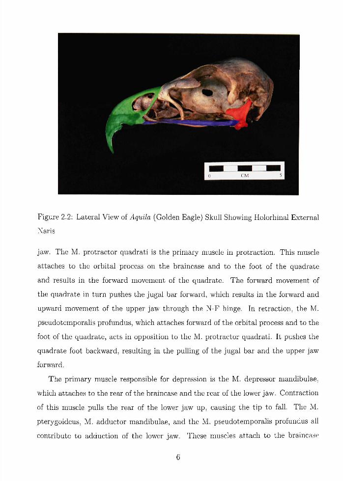
Figure 2,2: Lateral View of Aqmla (Golden Eagle) Skull Showing Holorhinal External
Naris
jaw. The M, protractor quadrati is the primary muscle in protraction. This muscle
attaches to the orbital process on the braincase and to the foot of the quadrate
and results in the forward movement of the quadrate. The forward movement of
the quadrate in turn pushes the jugal bar forward, which results in the forward and
upward movement of the upper jaw through the N-F hinge. In retraction, the M,
pseudotemporalis profundus, which attaches forward of the orbital process and to the
foot of the quadrate, acts in opposition to the M, protractor quadrati. It pushes the
quadrate foot backward, resulting in the pulling of the jugal bar and the upper jaw
forward.
The primary muscle responsible for depression is the M, depressor mandibulae,
which attaches to the rear of the braincase and the rear of the lower jaw. Contraction
of this muscle pulls the rear of the lower jaw up, causing the tip to fall. The M,
pterygoideus, M, adductor mandibulae, and the M, pseudotemporalis profundus all
contribute to adduction of the lower jaw. These muscles attach to the braincase
6

(frontal and rear) and to the lowci- jaw (h'ont of the joint with the quadrate). The
postorbital ligament, wliicdi at-taches to the postorbital prtjcess and to the lower jaw
in front of the joint at the ciuadrate, also aids in adduclion by acting as a spring,
pulling the k)wer jaw toward the brainca.se.
2,2 Meclianical Models of the Jaw
The avian skull can be represented biomechanically with six parts: the braincase,
quadrate, jugal bar, lowcn' jaw, upper jaw, and postnarial bar (or lateral bar), in
Figure 2,3,
N-F Hinge
Protraction ^^ ^^
Retraction
Adduction
Depression
M depressor mandibular
M protractor pterygoideus
Figure 2,3: Biomechanical Representation of the Avian Skull
A mechanical model of the skull is provided in Figure 2,4, The model includes
both rigid links and elastic structures. The jugal bar, postorbital ligament, and dorsal
bar were modeled as elastic structures, while the braincase, quadrate, postnarial bar,
ventral bar, and lower jaw were modeled as rigid links. All other anatomical elements
were ignored. Clearly, the ligament is an elastic structure. The rigidity of the jugal bar
7
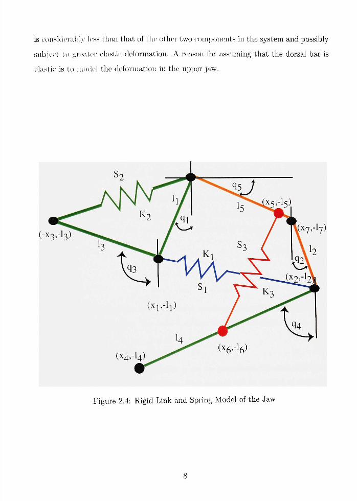
is cousitkn-al)l>' less than that of t he other two eonipcjiients in the system and possibly
subject ti) great-er elastit' deformation, A reason k)r assuming that the dorsal bar is
elastic is ti) nuxk'l the deformation in tlu; ui)per jaw.
Figure 2,4: Rigid Link and Spring Model of the Jaw
CHAPTER HI
MODELING THE JAW
Since t he a\'ian jaw is a complicated .system, with multiple anatomical parts that
possess a variet,\' of mechanical properties, no one method of modeling the system is
an t)b\-ious clu)ice. If the system were regarded as ccjiisisting of only rigid elements
in a ck)stHl chain, the dimensionality would be reduced at the cost of introducing
constraints. For such an approach, the Euler-Lagrange approach would not be the
is the most efhcient method. However, because there are no hard constraints for the
model that is presented here, it is the method that will be used,
3.1 Euler-Lagrange Method
The Euler-Lagrange method, begins with the calculation of the Lagrangian (L),
which is the difference in the kinetic (T) and potential {V) energies of the system,
L = T-V (3,1)
In general:
T = ^mv'^ and V = mgh
with mass m, velocity of the center of mass v, gravitational acceleration g, and h the
height of the center of mass. The Euler-Lagrange equations are given by,
^(f)-'^ = Q. (3.2) dt \dqj dg,
where g, are the generalized coordinates, qi are the generalized velocities, and Qi are
the generalized work done on the system. This method will be applied to derive the
equations of motion for the mechanical model shown in Figure 2,4,
3.1,1 The Upper Jaw
Referring to Figure 2,4, the system for the upper jaw includes four rigid links and
two springs. The generalized coordinates for this system are the angles 9 i , ©2, and

03, The link assot'iated with I he braincase is assumed fixed. The points {x^, L,) are
the position coordinates related to the ends of the lateral bar, quadrate, ventral, and
k)wer Jaw (Si'e Figure 2. I), The parameters /, and in, relate to the lengths and masses
of the lateral bar, ciuadrate, ventral bar, lower jaw, and the braincase.
First, we deri\'e the formulas for the lengths of the springs. We define 5, as the
length ot the spring at. rt'st, and .s, as the length of the spring during any stretching
or compressing. The k'ligth of ,si is the difference in position of the center of mass
of the iiuadrat(.' and the center of mass of the postnarial bar. The length of S2 is the
difference in position of the center of mass of the postnarial bar and the N-F hinge.
These lengths are functions of the angles 0 i , 02, and 03 given by:
.s = sJik sin 02 + xy + h sin 0 i )2 + ( 2 cos 02 + L7 - h cos 0i)2 (3,3)
S2 = Vih sin 01 - h cos ©3)2 + {l^ cos Qi + LT + k sin ©3)2 (3,4)
To derive the kinetic energy of the system, it is useful to view the lateral bar and
ventral bar as a double pendulum and the quadrate as a simple pendulum. Therefore,
one can show that the kinetic energy is given by
T = i ( m i + m.,)llel + m3/i/30i©3 cos(03 - 0 i ) + ^m^llQl + ^m^llQl (3,5)
For the potential energy, one must consider the effects to gravity and due to the
stretching of the spring. The potential energy due to gravity is merely m.ghi where
m, is the mass attached to the ith link and and /?., is the vertical component of the
length of the ith. hnk. The potential energy due to the spring is given by Iha} where
k^ is the spring constant for the ith spring and ai is the deformation in length of the
ith. spring. Therefore, it follows that
V = 5 r ( m i + m 3 ) / i ( l - c o s 0 i ) 4 - 5 ^ 2 / 2 ( 1 - c o s © 2 ) + 5 ^ 3 ^ 3 ( 1 - c o s © 3 ) -
\h{S,-S,f-\k2{S2-S2?.
10
The Lagrangian can be now be writt-en as
/- - -,{nii + //^3)/f0I + //'3/i/3©i©:iCos(©3 - ©i) + ^A//.3/l0^+
|/;/2/.^0r; - g{'nii + /;/:i)/i(l - cos©i) - grn^hil - cos©2)- (3,7)
</;//3/:,(l - cos ©3) + ^A:i(5, - .Si)'" + i/,:,(52 - ^2)^
.Xext, tlu' gent'raii/e work, ( , is (leriv(>(l. We assume there is resistance at a
node that corresponds t,o a. torsional sj^ring and the viscous effect. The torsional
resistaiKc is proportional to the change in ©, with constant AV The viscous damping
is proportional to 0 , with constant r,. Finally, we input an external torque T2{t) at
©2 that corresponds to the contraction of the M, protractor quadrati. Therefore, the
generalized force at a node i is
Q, = Tj(t) - CiQi - A'j
where T, (i) = 0 for / 7 2 and
[ax Ti <t <T2 T2={
I 0 otherwise
This choice of T2 is meant to model a step input that describes the moment generated
b>' a burst of muscle activity.
Using (3,2), we derive the following system of Euler-Lagrange equations:
dt l a e , i 901 = (mi -I- m3)/?0i + 7713/1/303 cos(03 - © 1 ) -
"73/1/303 sin(©3 - ©1) +5("T-i + m 3 ) / i s i n © i -
j-ki{Sx - Si)[/i cos©i(/i sin©2 + XT + h sin©i)-|-
/i sin ©i(/2 cos ©2 + I/7 - h cos ©i)]-|- (3-8)
—/C2(5'2 - S2)[/l COS©i(/i sinQi - /3COS©3)-
/i sin©i(/iCos©i + L-J + /3sin©3)]
= - c i © i - A : i ,
11
ill
and
01. ;;/2/.i;02 + .(///'2/2Hin©2 + j-J'-i{Si - si)[/2 cos©2(/2sin02+
,/-7 + /i sin ©1) - h sin ©2(/2 cos ©2 + L^ - li cos ©1)]
'I2 - ('202 - A:2,
(3,9)
dt \ot\J zkt = iii:d[k'r)\ cos(©3 - ©1) -f- 7/;,i/i/3;y2 sin(©3 " ©1) + ^3/303+
(7/;;3/3sin03 - j^k2{S2 - S2)[/3 sin03(/i sinOi - /3cos03) - f
/3 cos ©3(/i COS ©1 -h L7 -h I3 sin ©3)]
= -C303 - /C3,
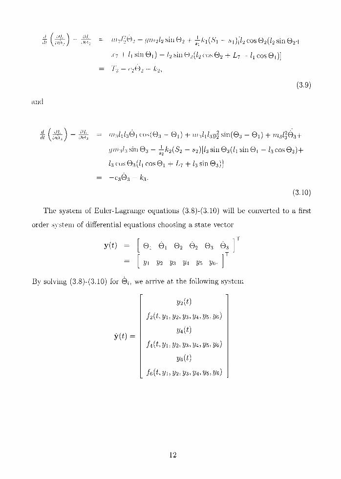
(3,10)
The system of Euler-Lagrange equations (3,8)-(3,10) will be converted to a first
order s\'stem of differential equations choosing a state vector
y{t) ©1 ©1 ©2 ©2 ©3 ©3
vi z/2 'm VA 2/5 ye-
By solving (3,8)-(3,10) for ©», we arrive at the following system
2/2 (t)
/2(t,2/l,y2, 2/3, 2/4, 2/5,2/6)
2/4(0
74(^,2/1,2/2,2/3,2/4, 2/5, 2/6)
2/6(0
/6(t, 2/1, 2/2, 2/3, 2/4,2/5,^6)
y{t) =
12

wnere
./'-- = [(/'•b'>'2 i/2 - A:|,s2.' 'i/2) siu(2//:,) + {-k^sis^k + k2SxS2k) sin(yi + y^) +
[k-iSysJ:, ~ Sik2S2l:i - '2lll•^l•xg^•,.sx.s•, + .Si/,;2.sv/3 - A:26'i52/.5) sin('i/5 - 2/l)
(,(/.si,s.2/;;3 -t- 2/,-i,s2.siL7 -I- 2/7,si,S2'/;ii - 2/,:iS2.S'iL7)sin(i/i)-|-
(-2A-i,s2'^^'|.''7 + 2A:|.s2,si.r7) c(js(//:i)-|-
(-A:i,s2.S'|/i -I- A:i,s._,.S|/2 - ki.S2Sil2 + A;iS2Si/i) sin('(/3 + yi) +
(-A:i.s.nS'i/i -I- A:i.S2.S|/2 - A:|.V25'i/2 + A:|S2Si/i) ,sin(-y3 + yi) +
,siA-2.S'_,/3siii(3y5 - •(/]) - A,'i,s2A'i/i-
,siA-2.s2/3sin(3-(/5 - i/i) + Aii.s^S'i/i - .yi5/m36'2sin(-;(/i -f- 2yr,)]/
[.s2/iSi/;i3Cos(2y5 - 2yi) - S2hsim.3 - 2s2liSimi]-
2[ -A ' i /3 - cit/2/3 + /iA"3 cos(2/5 - 2/1) + /1C32/6 cos(?/5 - y i ) ] /
[klj{-2nii + m-i cos(2t/5 - 2yi) - 7773)],
IA = [T2{f) - C22/4 - A'2 - 5 7772/2 sin7/3 - A;i(S'i - Si)
[/2Cosy3(/2sin'(/3 -t-X7 + lismyi) - /2 siny3(/2 cosy3 + L7 - /i cos?/i)]/si]/[7)72/i],
and
7761 + "62 •As = 3
(76
? 6i = {m3kiS2Sil2 + m3kiS2Sili - mj,kiS2Sili - mj,kiS2Sil2) sin(y5 - 2yx + 7/3)4-
{-m-ikxS2Sxl2 - m-ikxS2Sxlx + m-ikxS2Sxl2 + m-ikxS2Sxlx) sin(7/5 - 7/3) +
{m.'ikxS2Sxl2 + m'ikiS2Sxlx - m-ikxS2Sxlx - m'ikxS2Sil2) sin(7/5 - 27/i - 7/3)-
{-m-skxS2Sxk - rrfikxS2Sxlx + m-ikxS2Sil2 + n73A;iS2-''i/i) sin(7/5 -h 7/3) +
( —27?73 5iS2 — 2vVikxS2SxL7 — 2m-igsxS2mx + 2n73A;iS2'S'iL7) sin(7/5 — 27/i)-|-
(70.3A;2Si52/5 + 4A;25'2/3Simi - m.sk2SxS2k-
Ak2S2hsxmx - 3m3k2SxS2h + 37773A:23152/3) sin(27/5).
13

/ ; , ; • : - (-//;3A-2.si.S'2/,r, - 27;;r;/3'(yu,S|,y2 - in:J,:2-^iS2h + ni;,k2SyS2li +
'":iA2A'l• •2/5) sill(2//,s -2y\) +
{-ni^ki.s.i.sik, + ///3A:i.s2.Vi/2)sin(-2'7/3 + yr, - y^) +
(///aA'i.s'v.s'i/i - ///3A:i.s2.Vi/i)cos(/y,r, - 3'(/j)-H
(2;/;3.siA2,s2/i - 2;/;3.siA:2,V2/i) sin(y5 - 3yi)-|-
{lll:\k2SxS2l5 — "'3A'2'''l.S'2/5 + /"3 A:2''''lS2/3 —
/;;3A2.si52/3)sin(2yi) + {vi3kiS2Sxlx - iii-.ikxS2Sxlx) cos{yx +2/5) +
(4A-252/i.Si/;/i — 4/i:2.S.2/iSi//7i - G7//3,S|A;2S2/l +
6/;;3,siA-252/i)sin(7/i + y^) + [~AviJ.xyls2Sxmi~
•iinlsxlxgh^) sin(7/5 - yx) + {-2m-sgsxS2mx - 2m3kxS2SxL7-
2m3gsxS2 + 2m3kiS2SxLY) sin(7/.5) - 2m3kxS2Sxx-r cos{y3 -h 2/5 - 2/i) +
2»i3/ciS2S'i/i cos(7/5 - yx) - 2m3kiS2Sxlx cos(7/5 - 7/1)4-
inikxS2Sxl2 sin(27/3 + yz - yx) - 2m-ikxS2Sxx-j cos(-7/3 -h 2/5 - y i ) -
iUskiS2Sxl2 sin(27/3 -H 7/5 - 2/i) + 27773A;iS2SiX7 cos(7/3 4- 7/5 - 2/1)+
27773 A;iS2S 1X7 cos(-7/3 + 2/5-2/1)
and
de = -2Si?77^/3S2COs(27/5 - 27/1) 4- 2si777|/3S2 +4Sir773/3S2?Tl l ] -
2[-A'3/i?77i - Oiyahmx - 7773/1 A'3 - rnslxc^ye + msh'xk cos(7/5 - 7/1) +
m3Cxy2k COs(7/5 - 2 / l ) ] / [ / l " ^ 3 / 3 ( - 2 " ^ l + ?T73 COs(27/5 - 27/i) - 7773),
Once initial values are provided, this system can be integrated forward in time.
3,1,2 The Upper and Lower Jaw
Referring to Figure 2,4, the system for the jaw includes five rigid links and three
springs. The generalized coordinates for this system are the angles ©i, ©2, ©3, and
©4, ^ i , 52, Si, and S2 are the same as in the upper jaw, ^3 is the initial length of the
spring which attaches to the braincase and to the lower jaw while S3 is the length of
14
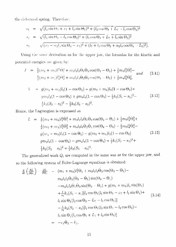
the (k4ornie(l spring, Ther(4oi-e,
•s'l = \ / ( /2s in02 + .;-7 + /i sin©i)2 + (/2Cos©3 + L7 - /i cos©1)2
,s-_. = \ / ( / , sin ©I - /3 c'os ©3)2 + (/i cos ©1 + L7 4- /3 sin ©3)2
.s:i = \/(.''7 - oo/i sin 0.1 - .(•5)2 _|_ (/.J, _|_ I., COS ©2 4- 0-2/4 cos ©4 — L^)'^).
llsing the same derivation as for the upper jaw, the formulas for the kinetic and
potential energies are given l)y:
T = i ( / / ; , + m3)/'f©'l + / / / 3 / i / 30 i03Cos (©3-©i )4 ->3 /3 '03+ , , . , , , a77a (3,11)
i ( / / /2 4- nh)f^e'^ + » M / 2 / | 0 2 © 4 cos(©4 - ©2) + ^7774/1©^
\ = 5(7/(1 -H //)3)/l(l - COS©i) -H 51(7772 + 7774)/2(l - COS©2)4-
y7;;3/3(l - c o s ©3) 4-57774/4(1 - c o s ©4) - ^kx{Sx - S i ) ^ - (3.12)
\k2{S2-S2)^-'^k3{Ss-S3)^.
Hence, the Lagrangian is expressed as
L = | ( m i + 7 7 7 3 ) / ? 0 ? + 7773/l /30103COs(©3-©l) + i7773/3'03 +
^{lllo + ni4)llQ2 + "^4/2/402©4 COS(04 - ©2) + ^ ^ 4 / ^ © ^ -
g{mx +m-i)lx{l - c o s © i ) - 5(777 2 + "^4)/2(1 - c o s © 2 ) - (3-13)
57773/3(1 - cos©3) - 57774/4(1 - cos©4) 4- ^A;i(Si - si)2-h
^fc2(52-S2) '4- | /C3(53-S3)^
The generalized work Q^ are computed in the same was as for the upper jaw, and
so the following system of Euler-Lagrange equations is obtained:
d.(^^'^_M. = (7771 +7773)/?©l+"73/1/3^3 C 0 S ( © 3 - © 1 ) -
m 3 / i / 3 © 3 ( 0 3 - 0 i ) s i n ( © 3 - © i )
-7T73/i/30i03 sin(03 - ©i) + 5("^l + "^3)/i sin(©i)
+ ^A;i(5i - si)[/i cos©i(/i sin©2 + xj + h sin©i) +
/i sin ©1 [I2 cos ©2 4- L7 - h cos ©1)]
- - A ; 2 ( 5 2 - S 2 ) [ / i c o s © i ( / i s i n 0 i - / 3 C o s © 3 ) -
Ix sin ©1 (/i cos ©1 4- L7 + k sin ©3)]
- - r i 0 i - A - i ,
15

d_ dt
ill. jJ-L {1112 + /;/|)/.]©2 4- ///,|''2A|0.i cos(©,, - © 2 ) -
ni 1/2/1© 1(01 - ©2) sin(©,| - ©2) - / / M / 2 / 4 0 2 0 4 sin(04 - ©2)4-
!l{ni2 4- ///4)/2sm(©2) + ^/ , ; , (5 , - Si)[/2 cos ©2(/2 sin ©2+
.(•7 + /i sin ©1) - I2 sin ©2(/2 cos ©2 + L7 - Ix cos ©1 ) ] -
i;A;3(53 - .^3)12 sin ©2(L7 + I2 C(JS ©2 + 02/4 cos ©4 - L5)
T2 ~ r202 - A-2,
(3,15)
d_ / 01. dt I yo;j
and
PL = iiisl'iQi + malxhQxCosiQ-s-Qx}-
" ^ 3 / i / 3 0 i ( 0 3 - 0 i ) s i n ( © 3 - © i )
4-777.3/1/3©103 sin(©3 -Qx)+ grri'ik s in(©3)-
^A;2(52 -S2)[/3sin©3(/isin©i -/3cos©3)-H
/3 cos ©3(/i cos Qx + LT + I3 sin ©3)]
= -C303 - A;3,
dL dt \deA
dL 504
(3,16)
(3,17)
= ?774/|04 4- 7774/2/462 COS(©4 - © 2 ) -
7774/2/402(©4 - ©2) Sin(©4 - ©2)
4-7774/2/402©4 s in (©4 - ©2) + gm^l^ s i n ( © 4 )
-j-^k-i{S3 - S3)[Q;2/4COS©4(.r2 - 02^4 s iu ©4 - ^5 )4 -
012/4 sin ©4(1/7 4- h cos ©2 4- 02/4 cos ©4L5)]
= —C/x\yA — A:4,
For the upper and lower jaw, the system of Euler-Lagrange equations are used to
derive the following first order system:
©1 01 ©2 ©2 ©3 ©3 ©3 ©4 1 ,^^„ , J (3,18)
2/1 2/2 2/3 2/4 y s 2/6 2/7 2/8
y(0 =
16

yit) =
V2{l)
J2{l/fj\> V2, 53, 54, VT., 5(i, yi, 58)
•2/4(/)
/ i (/, y 1, 52, 53, 51,2/5, 5(;, 2/7, ^8)
'2/6(/)
/6 ( / , 5 l , 2/2, 53, 54, 2/5, 56, 2/7, 58)
'2/8(0
/8(^, 5 l , 2/2, 53, 2/4,2/5, 2/6, 57, 2/8)
diere
/2 = [(2A-i,s25i.;-7 - 2A;li•2Sla•7)cos(53)4-
• ) s in (5 l )+
255) +
(3.19)
(25.si,s2//;i 4- gsxsrui.i + 2kxS2SxLj — 2kxS2SxLj'
(si7773/i5|s2 + Sxk2hS2 - S1/C2/1S2) sin(25i - 255^
(A:iS25i/i - A;iS2Si/i) cos(25i) + {-kxS2Sxlx + kxS2Sxlx-t
kxS2Sxl2 - kxS2Sxl2) sin{yx - 53) + (-A;iS2Si/i 4- A;iS25i/i-H
kxS2Sxl2 - A;iS2Si/2) sin(5i 4- 53) + (-A;iS2Si/2 4- kiS2Sxl2) sin(253)-h
{2k2l3SxS2 - 2k2l3SxS2 + 27773/356S1S2) s i n ( - 5 5 4- 51)+
A4S2S1/1 - kxS2Sxlx + Sxgm3.^2 s i n ( - 2 5 5 + yx)]/
[-2s2Sl/l777i 4- S2Sl/l7773 COS(255 - 2yx) - S2Si/i7n3]-
2[ -A '3 / i c o s ( - 5 5 + 5i) - C356/1 c o s ( - 5 5 4- 51) + Avi/3 + C152/3]/
[12/3(2777.1 - 7773 cos(25i - 255) + 7773)],
17
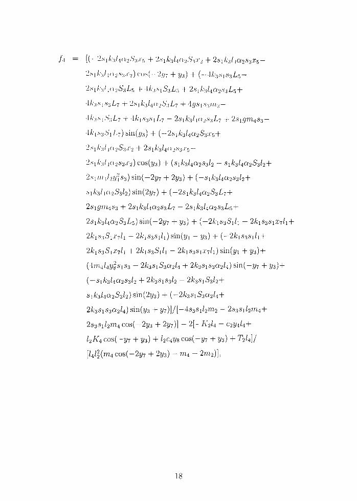
/ i = [(-2,siA3/40253.rr, 4- 2.siA:3/4n253:C2 4- 2siA:3Ai02S32;5-
2.s,A:,/|(i2.s3-C2)cos(-257 4-53) 4- (-4A;3.S|63L5-
2,siA-3/i(i253Lr, 4- lA-3,S|53Lr, + 28xic3ka2S3Lr^+
4A;i,S|,S3L7 4- 2.S|A;3/4n'253L7 4- 45,Si.S:j7/i2 —
4A':i.S|,S'3L7 4- 4A;i,S3SiL7 - 2A'iA;3/.|a'2.s';iL7 4- 2sigrn4S3~
•ikiS3.SxLY)s\n{y3) + {-2sxk3l4a2S3Xr,+
2.siA3/|(i253.r2 4- 2siA:3/4a2.s-3,r,5 —
2,siA-3/ia263J'2)cos(53) 4- (siA;3/402S3/2 - 5iA;3/402^3/24-
2,si//;,,/25.^S3) s i n ( - 2 5 7 + 253) 4- (-SiA:3/402S3/2+
.siA;3/ia253/2)sin(257) 4- ( - 2 S I A ; 3 / 4 Q ; 2 5 3 L 7 4 -
2S157774S3 4- 2SiA;3/4Q;253A>7 - 2SIA;3/402S3-A/5 +
2sxk3Ua2S3L^) s i n ( - 2 5 7 + 53) + {-2kxS3Sxlx - 2kxS3SxX7lx +
2kxS3SxX7lx + 2kxS3Sxlx) sin(5i - 53) 4- {-2kxS3Sxlx +
2kxS3SxX7lx 4- 2A;iS35i/i - 2A:iS3SiX7/i) sin(5i + 53)4-
(47;74/458SiS3 - 2A:3Si5302/4 4- 2A;3SIS3Q;2/4) s i n ( - 5 7 4- 53) +
(-SiA;3/402S3/2 4- 2A;3SIS3/2 - 2A;3SI53 /24-
SiA;3/4a253/2)sin(253) + {-2k3SxS3a2k+
2k3SxS3a2U) sin(53 4- 57)]/[-4s3Si^2"72 - 25381/277744-
23381/2^4 c o s ( - 2 5 3 4- 257)] - 2[-A'2/4 - C254/4-H
/2A'4 c o s ( - 5 7 4- 53) 4- /2C458 cos ( -57 -h 53) 4- T2/4]/
[/4/|(7774 C0s(-257 + 253) - 7774 - 27772)],
18

A; =
.5iL7)sin(25i -55)4-
255) +
[(- '" .3A-| .s '25| /2 + 7;/3A-|.s2.si/2 - 7/(3A'l.s^.S'i/i + m3kiS2Sxlx) s i n ( - 5 . 5 4- 251 4- 53)4-
(-/;/3/,-|,s2.S'i/2 4- /;/3A;i.s2.S|/2 -^ 7;/3A:|.S2.S'i/i 4- 7/73A:|.S2.si/i) s i n ( - 5 5 4- 251 - 53)4-
(25/;/3.s2.si///i 4- 2/;/:(A:i.s2.s'|L7 4- 2y//ySi5,S2 — 27?73A;iS25iL7) s in (55)4-
( -2 / / ;ySi5 .S2 4- 27/73A-|,S2.siL7 — 257/73.S2S17771 — 2in3kiS2S
{2iii3k2i3-'^\S2 - 27;;;iA-2/;!.si52 - 27/72/352S'lS2) s i n ( 2 5 i — 27
(- / / ;3A-i .s25i /2 4- ///,iA:i.S2.si/2 - y/7:iA:i.S25i/i 4- 7/73A:iS2Si/i) s in(55 + 53)4-
( —/;/3A'i.s25i/2 4- ///3A'|.s2Si/2 - ni3kiS2Sxlx + Tn3kxS2Sxlx) sm{ys, —
(-2/ / /3A' i , s2Si / i 4- 2 7 / / 3 A : i S 2 5 i / i ) c o s ( - 5 5 + 51)4-
(7773A:i.S2.Si/i - / /73A:iS25i/ i)cOs(35i - 55)-^
(///3A:i,s2ii/i - m3kxS2Sxlx) cos{yx + 55)4-
{-!ii3kiS2Sxl2 + 'i'^skxS2Sxl2) sm{2y3 - 55 4- 5 i ) +
(- / ; /3A;iS2Si/2 + m3kxS2Sxl2) s i n ( - 2 5 3 - 55 4- 51) +
(2777.3A:iS2Sli'7 - 2//i3A;iS25iX7) cos(53 - 55 4- 5 l ) +
(2ni3A-iS2Sia:7 - 27n3A;iS25iX7) c o s ( - 5 3 - ys + 5 i ) +
(4A:2/i.S2Si777i - 47773SiA:2/1^2 4- 47773SiA;2/lS2 - 4?n3/i5^S2Si
4A-2/i52Si7;7i - 47/i5.si/i52S2) s i n ( - 5 5 4- 5 1 ) ] /
m i —
[-4517773/3827^1 + 2sxmll3S2 C0S(255 - 251) - 2si777l/3S2]-
2[r773/lC356 4- 7773/IA:3 - 7773A"i/3 COS(-55 + 2 / l ) -
77730152/3 c o s ( - 5 5 4- 5i) + A'3/imi + csyehmx]/
[/l7773/i(2777i - 7773 COs(25i - 255) 4- 7773)],
19
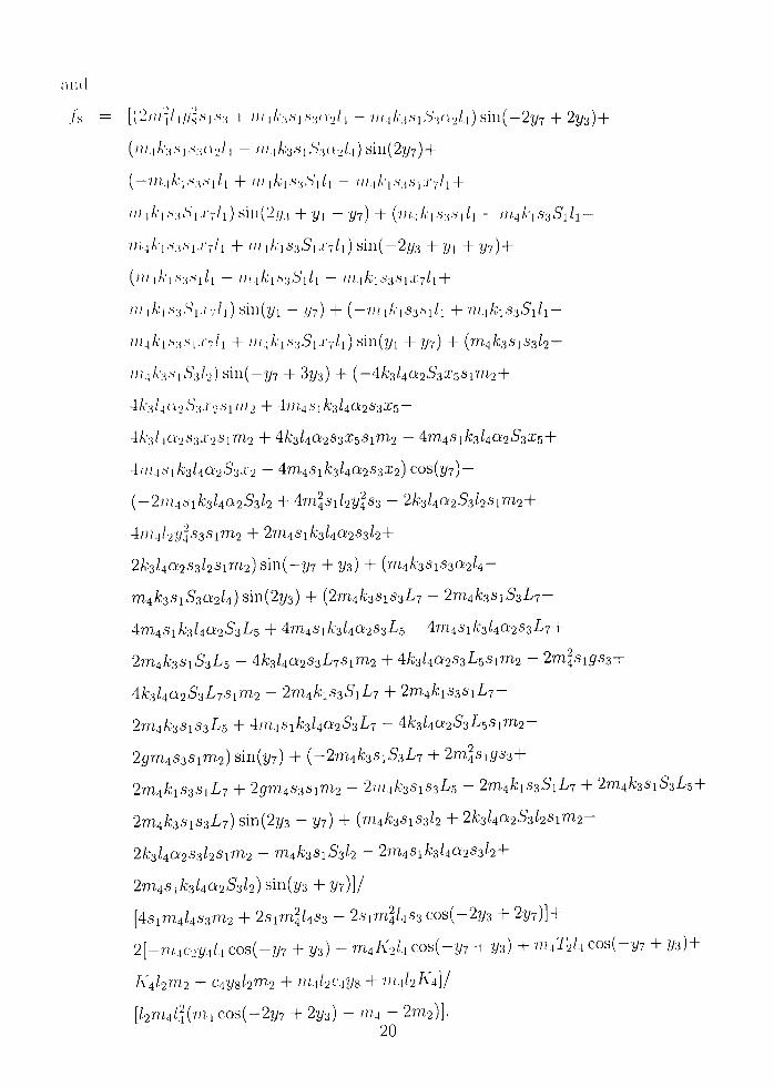
and
/ s = [(2///-J/ i52,si,s3 4- /// iA:3.si,s302/4 ^ ///1A/j.si5302/.!) s i n ( - 2 5 ? 4- 253)4-
(///.iA:,,si,s3n2/| - ///,iA:3.s,,S'3(i2/i)sin(257)4-
(-7;74A:i.S3,S,/i 4- 7//lA;|.S3,S'|/i - 7//,|A-i.S3,Si:;'7/i4-
/// iA-|.s35i.' '7/i) s in (253 + yx - 57) 4- (7//.,|A:i.s3,S|/i - 7// ,4A:i635i/i-
7;/4A-i,s3,si,c7/i 4- / ; / | / , ' i 5 3 5 i , / ' 7 / i ) s i n ( - 2 5 3 4-51 4 -57)4 -
(;//iA-i.s3,si/i - ///|A,'i,s35i/i - ///,|A;i53.six-7/i4-
/// iA-i,s'3.SV7/i) s i n ( 5 i - 57) 4- (-7//,|A-iS3.si/i 4- ni.xkiS3Sxlx-
/;/4A:i.s3,S|.c7/i 4- // /4A:i.s35i./:7/i)sin(5i 4 -57) 4- {m4k3SxS3l2-
///4A-3.Si53/2) s i n ( - 5 7 4- 353) 4- (-4A;3/4a253X5Si7772 +
4A'3/4a253a'25l/'/.2 4- 47//.45iA;3/4Q;2'S3X5 —
4A3/4a253.r2Si7772 4- Ak3l4a2S3X5Sxm2 — 47774SiA;3/40253X54-
4///45iA;3/4Q;253X2 - 47774SiA;3/4Q2S3X2) COS(57)-H
(-27/i4.SiA;3/4a253/2 4- 4777^Si/25|s3 - 2A;3/4a253/2Sl"^24-
4///4/254S3S17772 4- 27n4SiA;3/402S3/24-
2k3Ua2S3l2Sxm2) s i n ( - 5 7 + 53) + {m4k3SxS3a2U-
7774A;3315302/4) s in (253) + (27774A;3SiS3L7 - 27774A;3s 1 5 3 L 7 -
4777481 A;3/40253L5 4- 47774SiA;3/4a2S3-/^5 - 47774SiA:3/4a253^74-
27774A:35i53L5 - Ak3Ua2S3L7Sxm2 + Ak3Ua2S3L^sxm2 - 2mlsxgs3+
4:k3l4a2S3L7Sxm2 - 2m4kxS3SxL7 + 2mAkxS3SxL7-
2m4k3SxS3L^ + •\rn.xSxk3Ua2S3L7 - Ak3ka2S3LsSxm2-
25777483817772) sin(57) 4- {~-2m4k3SxS3L7 + 2mlsxgs3+
2m4kxS3SxL7 + 25777483817772 - 27//4A:3SiS3L5 - 2m4kiS3SiL7 + 27774A;3Si53L5+
27774A;38i83L7) s i n (253 - 57) 4- (m4A;3Si83/2 + 2k3l40i2S-il2Sxm2-
2k3l4a2S3l2SxVn2 - m4k3SxS3l2 - 2m4Sxk3l4a2S3l2 +
2m4Sxk3Ua2S3l2) sm(53 + 57)]/
[4817774/4837772 + 281777^/483 - 281777^/483 cos ( - 253 + 257)]-^
2[-7774C254/4 COS(-57 4" 53) - m4A'2/4 COs(-57 + 53) + '"42^2/4 COs(-57 4" 53) +
K4I2VI2 + 0453/2^^2 4- iiiikciys 4- 7//4/2A'4]/
[/27n,4/4('"4 c o s ( - 2 5 7 4" 253) - 7774 - 2777,2)].
20

3,1,3 Estimation of Data-
in owlcv to obtain data, for the simulations, lateral views of avian skulls were used.
Locations of cmittT of ma.ss wen' estimated, and an overlay of the links were then
addetl. Fi-oin these- figures, the lengths and angles were measured. To approximate
the masses, the formula 7// = fA' was used, where p is the density of bone {1.7g/cm^)
and r is the \'t)luine. Figures 2,1, 2,2, and 3,4 show the three skulls which were used
for the simulations.
Figure 3,1: Lateral View of Larus (Herring GuU) Skull with Overlay of Links
In Tables 3,1, 3,2, and 3.3, the data derived by the above method is listed alon^
with all constants used in the model.
21

Figure 3,2: Lateral View of Aquila (Golden Eagle) SkuU with Overlay of Links
3,2 Numerical Simulations
To integrate the system of first order differential equations derived from the Euler-
Lagrange method, the MATLAB odel5s solver was used. It should be emphasized
that the initial values for the joint angles were derived from the data described above
ahd are indicated by © ^ ins Table 3,1, The initial velocities were assumed to be zero.
The external torque generated at node 2 is assumed to act for ten milliseconds.
Using the data in Tables 3,1, 3,2, and 3,3, numerical simulations for the Larus, Aquila,
and Ramphastos skulls were computed.
When including the lower jaw into the simulation, changes in some constants were
made in order to produce physiologically meaningful simulations. For instance, the
values associated with passive joint torques and viscosities were modified. The choice
of these parameters requires some elaboration. For instance, the effect of the viscous
passive moment at a node was observed to exert rather insignificant alterations m the
simulations as compared to the passive joint torques, modeled as a torsional springs
22
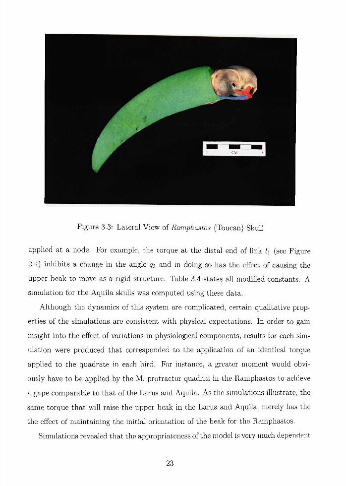
Figure 3,3: Lateral View of Ramphastos (Toucan) SkuU
applied at a node. For example, the torque at the distal end of link Ix (see Figure
2,4) inhibits a change in the angle 53 and in doing so has the effect of causing the
upper beak to move as a rigid structure. Table 3.4 states all modified constants. A
simulation for the Aquila skulls was computed using these data.
Although the dynamics of this system are complicated, certain qualitative prop
erties of the simulations are consistent with physical expectations. In order to gain
insight into the effect of variations in physiological components, results for each sim
ulation were produced that corresponded to the application of an identical torque
applied to the quadrate in each bird. For instance, a greater moment would obvi
ously have to be applied by the M, protractor quadriti in the Ramphastos to achieve
a gape comparable to that of the Larus and Aquila, As the simulations illustrate, the
same torque that will raise the upper beak in the Larus and Aquila, merely has the
the effect of maintaining the initial orientation of the beak for the Ramphastos,
Simulations revealed that the appropriateness of the model is very much dependent
23

Figure 3,4: Lateral View of Ramphastos (Toucan) Skull with Overlay of Links
on system parameters. For instance, it should be acknowledged that the inclusion of
the elastic structures introduces deficiencies in the model when system masses became
more significant, as in the case of the the Ramphastos, Here, the considerable mass
of the beak requires a large passive joint torque to insure that the three elements
in the upper beak act as one unit. Consequently, even a small change in 53 results
in an opposing torque that pushes the jugal bar against the quadrate, opposing the
muscular effects acting on the quadrate and modeled by the external torque applied
at node 2,
24
0.02
0.02
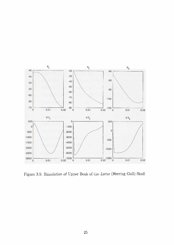
Figure 3,5: Simulation of Upper Beak of the Larus (Herring GuU) SkuU
25

4a,ble 3,1: Data for Pa.rt 1 Constant
h
/ • I
/3
/4
1-,
'G
' 7
0 I o
02„
030
040
©.-.,
Ui
Vo
V3
V4
rux
7772
7//3
7774
Oi
O2
M(4.1iod of Derivation
Aijproximation
Approximation
Approximation
Approximation
Approximation
Approximation
Approximation
Approximation
Approximation
Approximation
Approximation
Approximation
Approximation
Approximation
Approximation
Approximation
Vxp
V2P
V3P
V4P
k/h
k/h
Larus
1,75 X 10⁻²⁷//.
1,00 X IQ-'^m
3,25 X 10-2777
5,35 X 10⁻²r?2
4 ,25 X 10-2,,,^
3,06 X 10-2,77.
1,85 X 10-2777
-42°
-20°
-87°
-83°
6°
3.44 X 10-^777.3
4 ,42 X 10-^777^
5,74 X 1 0 - ^ m ^
1,05 X 10-^777^
5,84 X IO-U-5
7,51 X 10-U^5
9,76 X IQ-'^kg
1.79 X 10-^A:5
0,718
0,423
Aquila
2,69 X 10-2777
1,66 X 10-2777
1,14 X 10-2777
4 ,74 X 10-2777
6 ,11 X 10-2777
4 ,97 X 10-2777
1,54 X 10-2777
-33°
-23°
-78°
-85°
9°
2 .48 X 10-^777^
4 ,35 X 10-^777^
1,56 X 10-^777^
1,22 X 10-^777^
4 ,22 X 10-^A:5
7,40 X 10-^A:5
2 ,66 X 1 0 - ^ %
2 ,07 X IQ-'^kg
0,813
0,252
Ramphastos
1,94 X 10-2777
6.86 X 10-^777
4 ,63 X 10-2777
2 ,11 X 10-^777
2 ,63 X 10-2777
2 ,17 X 10-2777
6,29 X 10-^777
17°
- 5 °
-76°
-76°
22°
4 .98 X 10-'777^
7 ,03 X 10-^777^
6 ,33 X 10-^777^
5,42 X 10-^777^
8,47 X 10-'A;5
1.20 X 10-^A;5
1,08 X IQ-^kg
9,22 X lO-U-5
0,826
0,239
26

C\)nstant
n
X-2
X3
•'4
•i-5
• ' ' 6
•''7
Lx
L2
L3
L4
L,
Le
L7
Sx
52
53
4al)le 3,2: Data
.Mi-tlu)d of Derivation
/i s in©i
./•7 4-12 sin ©2
.ri 4- /3s in©3
i'2 4- /.I sin ©4
a'i.;'7
02X4
/5 COS ©-,
lx COS©i
Z/7 4- k COS ©2
Lx - /3COS©3
Z/2 4- k COS ©4
O1/5 sin ©5
L2 4- 02/4 COS ©4
k sin ©5
V ( x i - X 2 ) 2 + ( L i - L 2 ) 2
V4 + Ll ^ ( X S - 3:6)2 + (L5 - L6)2
for Simulat ions
Larus
- 4 , 0 3 X lO-'^
3,08 X 10-^
- 1 , 9 2 X 10⁻²
- 2 , 3 5 X 10^2
3,05 X 10⁻²
- 1 . 0 7 X 10⁻²
1,42 X 10-^
1,70 X 10⁻²
1,14 X 10⁻²
2,74 X 10-^
5,93 X 10⁻²
1,02 X 10⁻³
3,22 X 10⁻²
1,42 X 10⁻³
7.15 X 10-^777
3,34 X 10-2777
5.16 X 10-^777
Pa r t 2
Aquila
- 4 , 9 0 X 10-3
9,44 X 10⁻⁴
- 9 , 7 0 X 10-3
- 2 , 0 6 X 10⁻²
4,97 X 10⁻²
- 6 , 3 9 X 10⁻³
3,06 X 10⁻³
2,64 X 10⁻²
1,95 X 10⁻²
7,32 X 10⁻²
6.17 X 10⁻²
2,48 X 10⁻³
3.02 X 10⁻²
3,06 X 10⁻³
9,15 X 10-37^
1,12 X 10-2777
6,25 X 10-^777
Ramphas tos
1,83 X 10⁻³
3,01 X 10⁻⁴
- 1 , 7 1 X 10⁻²
- 5 , 6 5 X 10⁻³
2,16 X 10⁻²
- 5 . 0 9 X 10⁻³
3,20 X 10⁻³
1.93 X 10⁻²
1,01 X 10⁻²
3,90 X 10⁻²
2,93 X 10⁻²
2,65 X 10⁻²
1,47 X 10⁻²
3,20 X 10⁻²
9,36 X 10⁻²
4,26 X 10⁻²
2,92 X 10⁻²
27

Table 3,3: Data for Simulations P'Avt 3 Constant
y
P
kx
A-2
A:3
Cx
Co
C3
C4
A'l
A'2
A'3
A'4
ax
Tx
T2
Va,lues
9.81 A;5 • 77/./83
1700A;5/7773
200000
300000
100000
3
1
5
0.01
0.2
0
100
0
-1
0
0,01
Constant
Value
kx
2000
A:2
3000
^ 3
1000
A'l
0
A'3
0,01
C]
0,1
C2
0,1
C3
1
C4
0,1
Table 3,4: Data for Full Beak Simulation
28

-30
-40
-50
-60
-70 C
1000
0
1000
2000
3000
4000 (
"l
) 0.01
de
) 0,01
-30
-40
-50
-60
-70
-80
0.02 C
0.
-1000
-2000
-3000
-4000
-5000
-6000 02 C
^2
0.01
de,
) 0.01
-fO
-80
-85
-90
-95
^3
0.02 0 0.01
0.
0
-500
-1000
-1500 02 (
^^3
1 1 y D 0.01
0.02
0. 02
Figure 3,6: Simulation of Upper Beak of the Aqmla (Golden Eagle) SkuU
29
0
-0.02
-0.04
-0.06
-0.08 c
0
-1
-2
-3
-4 C
Ol
0.01 0.
de,
0.01 0.
-4.4
-4,5
-4,6
-4.7
-4.8
-4.9
-5 D2 C
60
50
40
30
20
10
0 32 C
9 2
•/o.aao
-76
-76.002
-76.004
-76.006
-76,008
-76.01
0.01 0.02 C
de^
o.c
1 )1 0.
-0.1
-0.2
-0.3
-0.4
-0.5
-0.6
-0,7 32 C
%
0.01
^^3
1
0.02
0.01 0. 32
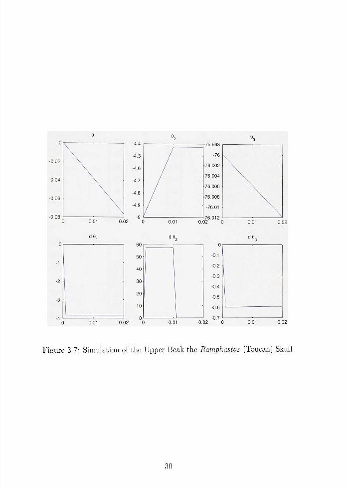
Figure 3.7: Simulation of the Upper Beak the Ramphastos (Toucan) SkuU
30
-32
-34
-36
-38
-40
-42
-44 C
3000
2000
1000
0
1000
2000
3000 C
e,
) 0.01
de
) 0,01
-24
-25
-26
-27
-28
0.02 C
0
-100
-200
-300
-400
-500
0,02 C
02
'8.05
-78.1
78.15
-78.2
78.25
0.01 0,02 • C
de
1—' ) o.c
2
r
50
0
-50
1 0.02 (
O3
) 0.01
'%
3 0.01
\
\-
\-
34.MO
34.96
34.97
34.98
54.99
0.02 C
2.5
2
1.5
1
0.5
0.02 C
94
0.01
^ ^ 4
) 0.01
0.02
0.02
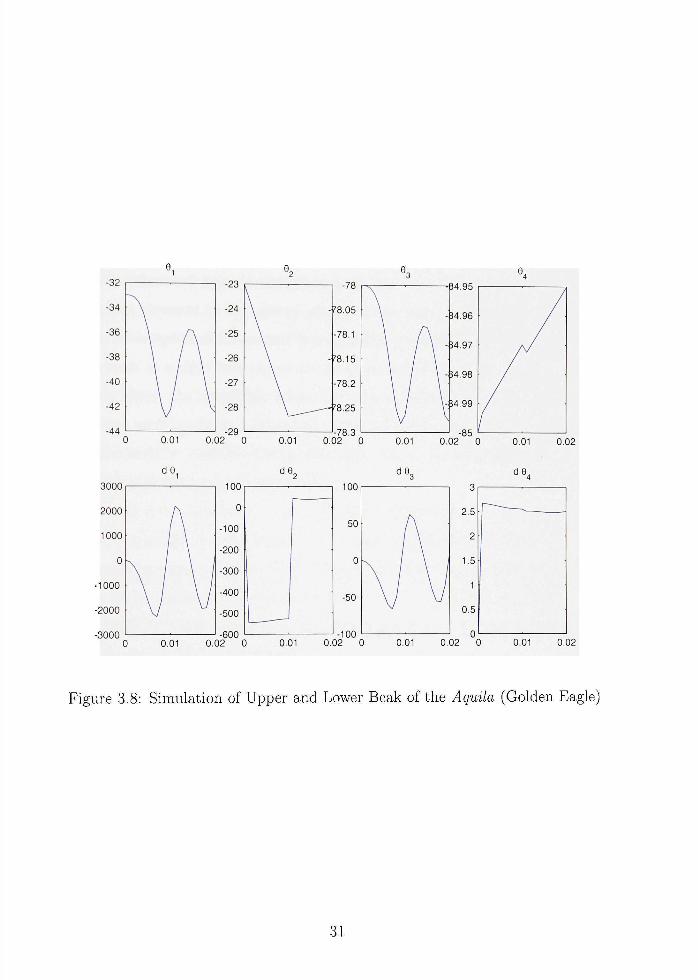
Figure 3.8: Simulation of Upper and Lower Beak of the Aqmla (Golden Eagle)
31

CHAPTEHIV
Discussion of Model and Future Directions
The modeling of tlu> anatomical structures as a combination of rigid bars and
elastic springs prox'ick-s a reasonable model when the masses of the component parts
are of t lie same relatiw size. In a bird such as the Ramphastos when the beak's mass
is of e)rck-rs larger than otlu>r elements in the system the model exhibits deficiencies
that were elaborated upon in the previous section. Certainly a case could be made
that certain elements in the system display some elastic deformation although an
alternatn-e viewpoint of the system that should be considered would be a model with
each element as a rigid link, except for the post orbital ligament. Such as approach
would eliminate the unrealistic forces that can be generated when the springs of
the current model undergo deformation. The model consisting entirely of rigid links
would also result in a system of lower dimension, but at the cost of greater complexity
associated with the kinematical constraints.
Although it has been argued that the elastic deformation in the beak should be
included in a model of avian kinesis, [11], a more exact model of these effects could
be obtained by using a hybrid parameter approach that would couple the rigid body
motions to the elastic deformations in certain components. In such an approach, bean
theory could be used to model the elements such as the beak and the jugal bar, where
elastic effects would be most likely to occur.
The incorporation of neural controls and muscular effects should also be incorpo
rated into the model. This will increase the computational complexity of the model
in several ways. Since each muscle will introduce second order dynamics and an equa
tion for muscle activation, the dimension of the system will be greatly increased. In
addition, the determination of neural controls will have to be addressed, Uffimateh', a
realistic analysis of cranial kinesis will depend on development of a three-dimensional
model based on realistic physiological data. This represents an extremely complicated
problem, both at the modeling and computational level,
32
BlBLlOGHAlMn
[1] Botlv, \ \ ' ,J . (1964) Kinetics (4' the avian .skull, .loiiriial of Morphology. 114:1-II,
[2] C4iapnian, C.B, and .Mitchell, .1,11, (1965) The physiology of exercise. Scientific .Inicriciin. 212:,SS !H>.
i.4l Chatterjee, S. (l!)!)9) i'lvohition of I he cranial kinesis. Pre-print
[4] t4iatterjee, S. (1997) The Kise of Birds: 225 Million Years of Evolution, Johns Hopkins Uni\-ersity Press, Baltimore,
[5] Dewood>', \ ' and Sclun'anec, L, (21)01) Hjiward dynamic model of gait with application to stress analwsis of bone. Mathematical and Computer Modeling, 33: 121-143,
[6] Martin, C,F, and Scho\'anec,L, (1999) The C(7ntr(4 and mechanics of human movement systems, Dijnaniical Systems. Control, Coding, Computer Vision: Sew Trends. Interfuees. and Interplay, G, Picci and D, Gilliam, Eds, Basel: Birkhauser, 173-202,
[7] Seliovanec, L. (2001) Modeling Human Movement Systems: Ocular Dynamics and Sk(,'letal S>'stems, IEEE Control Magazine. 21: 70-79,
.Nj \'an Den Heu\'el, \ \ ' ,F (1992) Kinetics of the skull in the chicken [Callus Callus Domestica.'i). Netherlands Journal of Zoology. 42:561-582.
[9] Van Gennip, E,.\I,S,J, and Berkhoudt, H, (1992) SkuU mechanics in the Pigeon, Culuniba IICKI. A Three Dimensional Kinematic .Mo(k4. Journal of Morphology. 213:197-224,
[10] \\4tnier, L,.M. and Rose,K,D, Biomechanics of the Jaw Apparatus of the Gigantic Eocene Bird Duitrgine: Implications for Diet and Mode of Life, Paleontology 17:95-120,
[11] Zusi,R,L, (1984) A functional and evolutionary anal>'sis of rhynchokinesis in birds, Smdfisoman Contributions to Zoology. 395,
3.4