Embed Size (px)
Citation preview

Facolta di Scienze e Tecnologie
Laurea Triennale in Fisica
Dynamical Depinning Transitionsin 2D: the Effect of Coverage
Relatore: Prof. Nicola Manini
Relatore esterno: Dr. Andrea Vanossi
Tommaso Meledina
Matricola n◦ 741164
A.A. 2012/2013
Codice PACS: 68.35.-p

2

Ai miei genitori, per la grande pazienza.
3


Dynamical Depinning Transitions
in 2D: the Effect of Coverage
Tommaso Meledina
Dipartimento di Fisica, Universita degli Studi di Milano,
Via Celoria 16, 20133 Milano, Italia
December 13, 2013
Abstract
In bounduary lubrication we investigate the occurrence of 2D dynamical
pinning between a rigidly moving layer of particles and the solitonic pattern
ensuing from the incommensuracy of the substrates underneath, leading to
a quantized velocity state; the effect is confirmed to occur for different
choices of the proportion between the spacing of the moving layer and the
solitonic pattern.
Advisor: Prof. Nicola Manini
Co-Advisor: Dr. Andrea Vanossi
5

Contents
1 Introduction 7
2 The Model 8
2.1 Dynamics . . . . . . . . . . . . . . . . . . . . . . . . . . . . . . . 8
2.2 Parameter scales and assumptions . . . . . . . . . . . . . . . . . . 9
2.3 The supercell . . . . . . . . . . . . . . . . . . . . . . . . . . . . . 10
2.4 Solitons . . . . . . . . . . . . . . . . . . . . . . . . . . . . . . . . 11
2.5 The quantized velocity ratio . . . . . . . . . . . . . . . . . . . . . 11
3 Computations 14
3.1 Matched case . . . . . . . . . . . . . . . . . . . . . . . . . . . . . 14
3.2 Mismatched case . . . . . . . . . . . . . . . . . . . . . . . . . . . 15
4 Discussion and Conclusions 17
4.1 Depinning in mismatched conditions . . . . . . . . . . . . . . . . 17
4.2 Non-unicity of the sliding state . . . . . . . . . . . . . . . . . . . 18
4.3 Conclusions and outlook . . . . . . . . . . . . . . . . . . . . . . . 21
Bibliography 25
6

Figure 1: a) Top view of the three stacked layers, bottom particles
in pink (light grey), lubricant particles in black, top particles bigger,
blue (dark grey). b) Top view of the model without the top layer.
Solitons are highlighted.
1 Introduction
In bounded lubrication, due to an external action two crystalline substrates slide
relatively to each other with a third atomically thin layer in between acting as
a lubricant. Simulations indicate the occurrence of a dynamically pinned state
characterized by the lubricant sliding at a fixed speed ratio relative to the advance-
ment velocity of one of the substrates. This feature has been studied thoroughly
in 1D [1-9] and 2D [10, 11], and more recent works [12, 13, 14, 15] suggested its
occurrence in 3D geometry as well; we seek to further explore the 3-dimensional
case, focusing on the role covered by the proportion between particles from dif-
ferent 2D layers.
In detail, we simulate the substrates by perfect hexagonal 2D layers, and fix
the reference frame where the bottom layer stands still, the top layer slides rigidly
with constant velocity vext while the top and bottom particles reciprocal positions
are fixed, and the lubricant particles are free to move under the effect of Lennard -
Jones potentials accounting for all lubricant-top, lubricant-bottom and lubricant-
lubricant interactions. We take the lattice orientations such that their crystalline
directions are parallel to each other, and choose the layers lattice spacings such
that the bottom and lubricant layers have different yet similar spacings ab and
ap, while the top layer has a significantly looser periodicity (Fig. 1a).
Under these conditions the lattice spacing mismatch between the bottom
and the lubricant layer determines a Moire pattern and, once a steady regime is
reached, the lubricant substrate develops corrugations, which form an easy-to-
slide solitonic pattern (Fig. 1b). As long as the top substrate spacing matches
that of the mobile pattern of solitons, simulations suggest that it tends to pin the
underlying pattern, dragging the lubricant particles forming the solitons along.
7

Since only a fraction of the lubricant particles are dragged directly by the
top layer while the others are standing practically still in the bottom-layer hollow
binding sites, the lubricant time-averaged center-of-mass velocity vcm assumes a
value which is proportional to vext and depends uniquely on the mismatch ratio
between the spacing of the bottom and lubricant layer. In other words the ratio
w ≡ vcmvext
is quantized to a specific value. This soliton dragging holds for any choice of the
external velocity vext, up to a critical velocity value vcrit at which the top layer’s
motion becomes so fast that it unpins.
Given the top layer spacing at and the spacing asol between adjacent solitons,
we introduce
θ ≡ at/asol. (1)
This parameter, which we will call coverage, represents the proportion between
the wavelengths of the top layer and the solitonic pattern; our work seeks to
investigate the occurrence, or lack thereof, of the dynamical pinning when the
top layer spacing fails to match that of the solitonic pattern, i.e. when θ 6= 1.
2 The Model
2.1 Dynamics
As anticipated, two confining solid surfaces are represented by two perfect rigid
crystalline mono-atomic layers, with a monolayer of lubricant particles in between.
Each layer is composed by point-like classical particles forming, at least initially,
hexagonal lattices. For the lubricant we should consider also multiple layers, but
for lack of time we focus on a single monolayer.
The reciprocal positions of both top and bottom particles are fixed, while
the lubricant atoms are free to move under a Lennard-Jones potential for each
lubricant-lubricant, lubricant-top, and lubricant-bottom interactions. These LJ
potentials take the general form
φLJ(r) = ǫ
[
(σ
r
)
12
− 2(σ
r
)
6]
(2)
and therefore have a minimum of depth ǫ at distance r = σ; the LJ interaction
is truncated at a cutoff radius RC = 2.5σ The equation ruling the j -th lubricant
8

particle is then:
mrj = −Nt∑
it=1
∂
∂~rjφt,p(|~rj − ~rit |)−
Np∑
j′=1
j′ 6=j
∂
∂~rjφp,p(|~rj − ~rj′|)+
−Nb∑
ib=1
∂
∂~rjφb,p(|~rj − ~rib|) + ~fdamp j + ~fj(t) (3)
where ~rj is the j -th lubricant particle’s position, while ~rit and ~rib are the positions
of the it-th and ib-th top and bottom particles respectively; Nb, Np and Nt are the
number of bottom, lubricant and top particles; φb,p, φp,p and φt,p are the two-body
LJ potentials defined above, each one defined by appropriate choices of σ and ǫ.
Since it takes an external force to keep the top layer moving at the fixed
speed vext, heat dissipation coming from Joule heat must be taken into account:
call ~Ffrict the total force needed to maintain the top layer motion at fixed velocity,
the work of this friction force (namely the Joule heat originating from it) will be
Wfrict =
∫ τ
0
Ffrictvextdt = vext
∫ τ
0
Ffrictdt = τvextFfrict. (4)
A simple yet effective representation of heat dissipation into the substrates con-
sists in a standard implementation of Langevin dynamics: we introduce a damp-
ing term ~fdamp(t) and a Gaussian random force ~fj(t) to be added to the force
acting in Eq. 2 on each lubricant particle.
The damping term includes symmetric contributions representing the energy
dissipation into both top and bottom substrates
~fdamp j = −η~rj − η(~rj − ~rt). (5)
while the Gaussian term is built in order that the relation
〈fjx(t)fjx(t′)〉 = 4ηkBTδ(t− t′) (6)
is respected on the x axis, and likewise for the y and z components, so that in
a non-sliding regime (vext = 0) this Langevin thermostat brings to a stationary
state characterized by standard Boltzmann equilibrium average kinetic energy of
the lubricant
〈Ek〉 = 3Np1
2kBT. (7)
2.2 Parameter scales and assumptions
Typical length scales of the system include the layers lattice spacings (three dif-
ferent values ab, ap and at for bottom, lubricant and top layer): the LJ potential
9

Physical quantity Natural unit Typical value
length ab 0.2 nm
mass m 50 a.m.u. = 8.3 · 10−26 kg
energy ǫpp 1 eV = 1.6 · 10−19 J
time abm1/2ǫ
−1/2pp 0.14 ps
velocity m−1/2ǫ1/2pp 1400 m/s
force a−1
b ǫpp 0.8 nN
Table 1: Natural units for several physical quantities.
scales accordingly, as we take σtt = at, σbb = ab for bottom and top rigid layers,
and σpp = 1.01ap for the lubricant layer, accounting for non-nearest neighbor
interactions.
Approximations for σtp and σbp are suggested by the Lorentz-Berthelot mix-
ing rules
σtp =1
2(σtt + σpp), σbp =
1
2(σbb + σpp). (8)
however, since σtt and σbb are fixed to the respective lattice spacings and thus do
not correspond to the actual ranges of interaction, these mixing rules tend to lose
their meaning; we will therefore explore other values of σtp as discussed later on.
We will express all quantities in this work as dimensionless numbers, refer-
ring to a set of units of measure natural to the physical system we are considering;
the physical scale is given by the typical values of energy, length and mass in-
volved; Tab. 1 collects natural units and typical values for the most relevant
quantities.
2.3 The supercell
To describe a macroscopic sample we need to compute the dynamics for huge
layers, hence a very large number of particles; to circumvent this issue we use
periodic bonduary conditions in the xy plane: two vectors ~acell1
and ~acell2
of length
L generate a supercell, enclosing the appropriate number of particles from all
bottom, lubricant and top layers. The supercell is then replicated ad infinitum
by means of rigid translations, and computations are carried out so that each
particle in the box interacts not only with every other particle inside the box, but
also with their translated images in the nearest neighboring cells.
Since we chose parallel crystalline directions for the three layers, the super-
cell’s base vectors ~acell1
and ~acell2
just need to be aligned to the lattices, and their
length L chosen as an integer multiple of every lattice spacing. For our work’s
10

first steps we take ab = 1, ap = 3/4 and at = 3 as a matched case, so that the
smallest supercell would be obtained by taking L = 6; we choose to take L = 18
instead, in order to display a satisfying number of top particles in our represen-
tations. Later on we will change at (and thus θ) and test the occurrence of the
pinning behavior.
2.4 Solitons
As shown in Fig. 1b the slight mismatch between the bottom and lubricant layers
lattice spacings results in a Moire-like secondary pattern; the image itself is just an
optical effect but the pattern lines correspond to actual dislocation lines, “empty”
lines to whom the top particles can pin.
It is indeed clear from the simulations that after a transient time (mostly
due to the damping term we introduced in Eq. 3) the lubricant substrate acquires
a corrugation matching the Moire pattern, i.e. an arrangement of empty lines
matching those of the optical pattern. As the top layer moves at velocity vext and
pins to the lubricant substrate, the latter moves as well, so that the Moire pattern
lines shift their positions and the substrate corrugation changes accordingly. As
anticipated above, we will call these mobile vacancy lines solitons, referring to
the very definition of solitary waves as pulses that maintain their shape while
traveling at constant velocity; the soliton spacing is given [16] by the 1D geometric
mismatch condition
a−1
sol = a−1
p − a−1
b . (9)
2.5 The quantized velocity ratio
The main feature characterizing the existence of a dynamical pinning behavior
is the quantization of the ratio between the time-averaged lubricant center of
mass velocity vcm and the external velocity vext, which acquires a constant value,
uniquely dependent on ap and ab, i.e. on the lattice spacing mismatch generating
the solitonic pattern. One could also write the w ratio in terms of Φp and Φvextp ,
respectively the mean flux of lubricant particles crossing a line perpendicular to
the pulling direction x and the hypothetical flux of lubricant particles moving
across such line, all with full speed vext; in formulas
w ≡ vcmx
vext=
Φp
Φvextp
. (10)
Rewriting w in terms of a flux ratio proves useful to evaluating in detail the
dependence of w from the lattice spacings, since we can give an explicit expression
of both Φp and Φvextp .
11

dLy
v
v
Figure 2: A train of lines, spaced by a distance d, moves at speed v
and crosses a segment Ly at angle ν.
We first compute the length δsol of a single soliton crossing the line in a time
δt
δsol = vδtcosν
sinν(11)
where we called v the pulling velocity and ν the angle formed by the solitonic line
with the Ly direction (Fig. 2); we then evaluate the mean length of soliton lines
crossing Ly for a train of parallel soliton lines separated by a mutual distance d
V =δsolδt
Ly sin ν
v
v
d= v
cosν
sinν
Ly sin ν
d=
Ly
dv cos ν, (12)
where d/v represents the time between two successive solitons starting to cross
Ly, and (Ly sin ν)/v the time it takes for one such crossing to occur.
We apply this general result to the case of a solitonic pattern formed by
a lattice spacing mismatch between two aligned triangular lattices, substituting
d = asol√3/2 and, in reference to Fig. 3, taking ν = π/2 for solitons of type 3
and ν = ±π/6) for type 1 and 2; using Eq. 12 the total speed of solitons crossing
Ly is then
V1 =Lyvext cos
π6cos π
6
asol√3/2
=2Lyvext√3asol
cos2π
6(13)
V2 = V1 (14)
V3 = 0 (15)
Vtot = V1 + V2 + V3 =
√3Lyvextasol
. (16)
12

12
3
d = a sol
π/6−π/6
π/2
Figure 3: Triangular soliton lattice, each line moves perpendicularly
at its own direction.
As a next step, we evaluate the flux of mobile particles associated to the advancing
soliton lines. We remark that (i) in-registry particles in between solitons do not
contribute to sliding, as they are trapped in individual minima of the corrugation
potential; (ii) a soliton line represents a single line of extra particles; (iii) as the
soliton lines are parallel to the lattice crystalline direction, the line density of
such extra particles along a soliton is simply the reciprocal lattice spacing of the
lubricant a−1
p ; (iv) roughly one half of each soliton is composed by particles in
the region in between soliton-crossing areas, far from the lattice triangle corners,
and therefore belonging uniquely to that soliton, while the other half particles,
close to the crossing sites, belong to three different lines. The ensuing total linear
density is
ρsol =1
2(1 +
1
3)a−1
p =2
3a−1
p . (17)
By multiplying this atomic linear density by Vtot we obtain the total flux of
lubricant particles crossing Ly per unit time, due to solitonic advancement
Φp =2Lyvext√3apasol
. (18)
Finally, by substituting Eq. 9 for asol, we evaluate w as
w =Φp
Φvextp
=
2Lyvext√3apasolLyvext√3a2p/2
= 1− apab. (19)
Given our choice of ab = 1 and ap = 3/4, we expect the reduced velocity plateau
to sit at w = 1− abap
= 0.25.
13

0 50 100time
0.22
0.24
0.26
0.28w
Figure 4: Transient on w ratio as a function of time, lasting ∼ 50
time units.
3 Computations
3.1 Matched case
We probe the theory sketched in Sec 2.5 by means of MD simulations carried out
at temperature T = 0 K, each run lasting 300 time units in order to give the
system plenty of time after the initial transient (around 50 time units long, see
Fig. 4) and collect a sufficient amount of data for averaging. When the motion
is periodic, we wrote a script that makes sure that average values of fluctuating
quantities (such as vcm) are always evaluated over integer multiples of the period,
in order to minimize systematic errors.
In order to both gain confidence with the computational tools and set a
starting point for the parameter fine-tuning we run a huge number of calculations
for the θ = 1 case (i.e. at = 3), with σtp spanning the range 0.5 to 3.5 distance
units. Every simulation tests the system through multiple runs starting from
vtop = 0.1 and then and raising it, up to vext ≥ vcrit when depinning is observed.
From a physical point of view, changing the σtp parameter means modifying the
equilibrium range of the top-lubricant interaction. One can therefore see our
parameter tuning as testing the quantized velocity effect on different materials
and surface corrugation levels.
As already stated in Eq. 19, the pinned state results in the w ratio gaining a
constant value, proportional to vext and uniquely dependent on the bottom and
14

0 0.5 1 1.5 2 2.5 3 3.5 4v
ext
0.1
0.15
0.2
0.25
0.3
w
0 50 100 150 200 250 300time
0.1
0.2
0.3
0.4
wFigure 5: (a) w ratio as a function vext for a θ=1 configuration with
σtp=3.00: the quantized velocity state is picked up instantly and lasts
until vext = 3.3, where pinning breaks. (b) w ratio as a function of
time for the same configuration, running at vext = 0.3.
lubricant layers lattice spacings; a quantized configuration will therefore show a
steady plateau for the w ratio as a function of vext, as in Fig. 5a. We take vcritas the the largest value of vext for which the plateau still holds, possibly running
extra simulations for a finer determination of vext. In general we are satisfied
by uncertainty around 10%. A further characterization of the quantized state
is observed in the graphs of the time evolution of the w ratio: such quantity is
expected to oscillate around the desired value, with a periodical behavior due
to the single particles periodically shifting from hollow sites (thus low or null
velocity) to excited sites where they get dragged by the top particles (i.e. their
velocity equals vext, see Fig. 5b). Outside the quantized plateau, no periodic w
oscillation is generally observed.
The effect is well-verified in most cases, basically whenever σtp is not so small
that the top-lubricant interaction range becomes too short and the top layer grabs
the lubricant substrate completely resulting in w=1 as in Fig. 6.
3.2 Mismatched case
We set simulations breaking the θ = 1 condition by adding or removing one or two
rows of particles in each top-lattice crystalline direction, and doubling or halving
the number of particles per row, for a total of six θ 6= 1 cases collected in Table 2;
these simulations are carried out at generally lower values of vext (starting from
vext =0.01 instead of 0.1) since vcrit is expected to decrease substantially as we
move away from the matched case.
15

0 0.2 0.4 0.6 0.8v
ext
0
0.2
0.4
0.6
0.8
1
w
Figure 6: The w velocity ratio for a θ=1 configuration with a very
small σtp=0.5. The lubricant layer sticks to the top layer completely.
The solitonic corrugations are disrupted, and most or all of the lubri-
cant particles are dragged along at full speed vext.
Occurrence of the dynamical pinning phenomenon is indeed less frequent
than in the matched case, but exploration over different values of σtp reveals that
the effect still takes place, although with generally smaller values of vcrit. Like in
the matched case, the quantized state is characterized by the w ratio oscillating
periodically in time around the value predicted by Eq. 19, although with a much
wider amplitude (Fig. 7).
Fig. 8, 9, 10 report the θ dependency of the critical velocity for σtp = 1.25
σtp = 2.00 and σtp = 3.00, which provide a good overview of the dynamical
depinning phenomenology. A number of θ 6= 1 configurations show null vcrit, i.e.
the top atoms are unable to pin the substrate at any vext explored (Fig. 11).
For θ = 1.2 we could not confirm any value of σtp producing the quantized
sliding state. We reduced the vext range by a factor 10, and still found no sign
of the quantized motion (Fig. 12), we thus conclude again that vcrit = 0 for this
case.
All other mismatched θ 6= 1 configurations instead do lead to the quantized
state, although with vcrit generally smaller than for θ = 1, see Figs. 8-10.
16
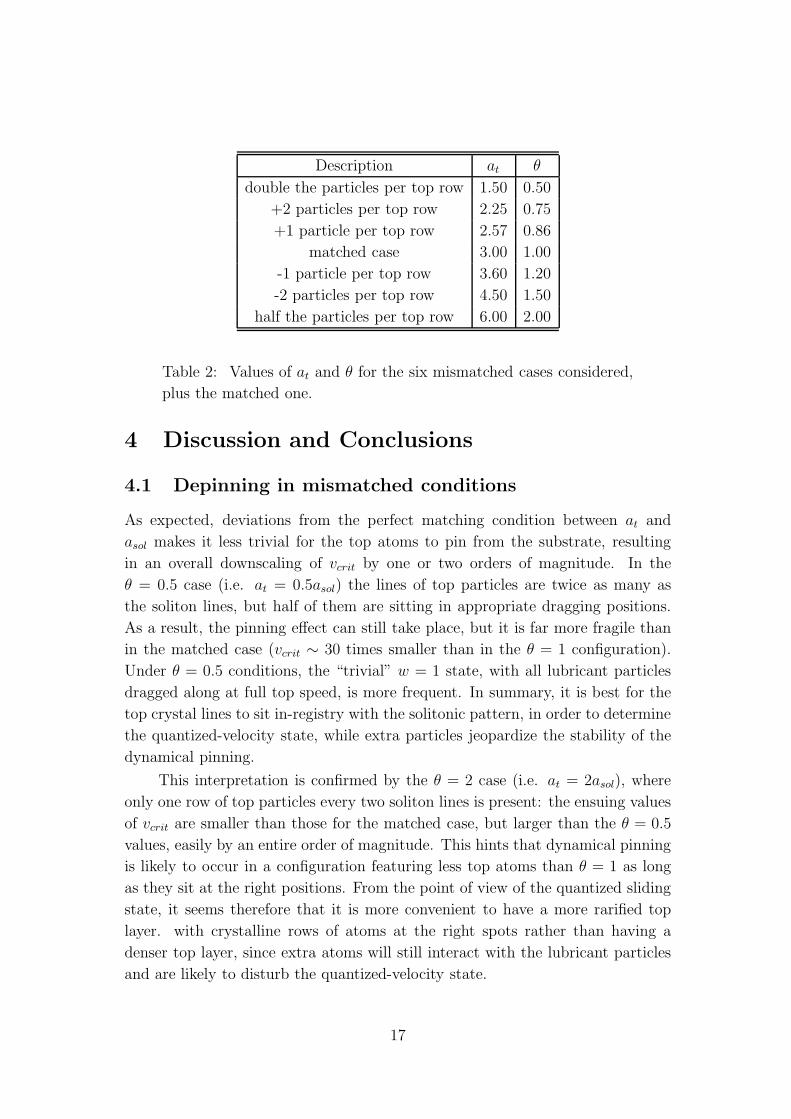
Description at θ
double the particles per top row 1.50 0.50
+2 particles per top row 2.25 0.75
+1 particle per top row 2.57 0.86
matched case 3.00 1.00
-1 particle per top row 3.60 1.20
-2 particles per top row 4.50 1.50
half the particles per top row 6.00 2.00
Table 2: Values of at and θ for the six mismatched cases considered,
plus the matched one.
4 Discussion and Conclusions
4.1 Depinning in mismatched conditions
As expected, deviations from the perfect matching condition between at and
asol makes it less trivial for the top atoms to pin from the substrate, resulting
in an overall downscaling of vcrit by one or two orders of magnitude. In the
θ = 0.5 case (i.e. at = 0.5asol) the lines of top particles are twice as many as
the soliton lines, but half of them are sitting in appropriate dragging positions.
As a result, the pinning effect can still take place, but it is far more fragile than
in the matched case (vcrit ∼ 30 times smaller than in the θ = 1 configuration).
Under θ = 0.5 conditions, the “trivial” w = 1 state, with all lubricant particles
dragged along at full top speed, is more frequent. In summary, it is best for the
top crystal lines to sit in-registry with the solitonic pattern, in order to determine
the quantized-velocity state, while extra particles jeopardize the stability of the
dynamical pinning.
This interpretation is confirmed by the θ = 2 case (i.e. at = 2asol), where
only one row of top particles every two soliton lines is present: the ensuing values
of vcrit are smaller than those for the matched case, but larger than the θ = 0.5
values, easily by an entire order of magnitude. This hints that dynamical pinning
is likely to occur in a configuration featuring less top atoms than θ = 1 as long
as they sit at the right positions. From the point of view of the quantized sliding
state, it seems therefore that it is more convenient to have a more rarified top
layer. with crystalline rows of atoms at the right spots rather than having a
denser top layer, since extra atoms will still interact with the lubricant particles
and are likely to disturb the quantized-velocity state.
17

0 50 100 150 200 250 300time
-0.5
0
0.5
1
1.5
2
w
Figure 7: w ratio as a function of time on a quantized-velocity state,
for a configuration θ = 0.75; a periodical behavior is still present, but
more noisy.
Surprisingly, simulations for non-multiple θ 6= 1 configurations, where the
top substrate spacing and the solitonic pattern spacing are further mismatched so
that top particles hardly ever sit on the optimal locations for dragging the solitons,
still realize non-trivial pinning regimes for several choices of σtp and unpin at vcritvalues comparable (albeit smaller) to those calculated for multiple−θ mismatched
configurations. This widespread occurrence of the quantized-velocity behavior
outside the full-matching conditions might suggest that such effect is achievable
for any value of the coverage θ, as long as the appropriate, most convenient
choices for the LJ parameters are made. However this is very unlikely to be the
case: certain regions in the LJ parameters phase space can be unaccessible, due
to various side effects occurring for limit values of the parameters, such as the top
layer completely attracting the lubricant particles when σtp is too small, or the
lubricant state curling up in 3D droplets if the lubricant-lubricant LJ potential is
too deep. This general observation might explain why, for θ = 1.2 configurations,
we failed to spot the pinning behavior for any choice of σtp (not restricted to the
three examples of Figs. 8-10).
4.2 Non-unicity of the sliding state
A peculiar feature characterizing the quantized plateau is its hysteretical behavior
as a function of vext. If we attempt to reach the quantized-velocity state down-
18

00.12 0.11
2.3
00.16
0.24
0.4 0.6 0.8 1 1.2 1.4 1.6 1.8 2θ
0
1
2
3
v crit
Figure 8: vcrit as a function of θ for σtp = 1.25, each point is deter-
mined by a sequence of calculations carried out in steps of increasing
vext as in Fig. 5a, until depinning occurs.
0 0.08 0
3.1
00.09
1.3
0.4 0.6 0.8 1 1.2 1.4 1.6 1.8 2θ
0
1
2
3
4
v crit
Figure 9: vcrit as a function of θ for σtp = 2.00.
0.090 0
3.1
00.09
0.6
0.4 0.6 0.8 1 1.2 1.4 1.6 1.8 2θ
0
1
2
3
4
v crit
Figure 10: vcrit as a function of θ for σtp = 3.00.
19

0 0.02 0.04 0.06 0.08 0.1v
ext
0
0.05
0.1
0.15
0.2
0.25
w
Figure 11: w as a function of vext for σtp = 3.00 and θ = 0.75, no
pinning occurs.
wards in vext starting from velocities above vcrit we generally do not restore the
same dynamical state for the same vext, see for example Fig. 13.
In principle, one could repeat every simulation we carried out, searching
for a critical re-pinning velocity (instead of an unpinning one) from above; if
the system reaches the quantized-velocity state, further lowering vext will only
make the state easier to maintain, so that the quantized state will extend down
to eventually vext = 0. This hysteretical behavior is understood as due to the
dynamical nature of the solitons. Coming from low velocity a pre-formed solitonic
pattern is there, ready to be grabbed. As vext is increased, the ordered “dance”
of solitons resists quite large values of vext before being disrupted and gives way
to chaotic dynamics. On the contrary, when starting from the chaotic high-speed
state, no solitons really are there to be pinned until, at a significantly lower speed,
not enough power is transferred to the lubricant, which eventually re-forms the
solitonic pattern, ready for dragging. As vcrit is not the same in the two cases,
the intermediate hysteretic region is characterized by a sliding state which is not
a unique function of vext.
Referring to Table 1 we note that the unit velocity is 1400 m/s, therefore
even a slow vcrit around 10−2 velocity units still correspond to several meters
per second, and therefore indicate a positive outcome for typical experimental
velocities.
20

0 0.002 0.004 0.006 0.008 0.01v
ext
0.001
0.01
0.1
w
Figure 12: w over vext for σtp = 3.00 and θ = 1.2, vext is ten times
smaller than the usual values but the quantized-velocity state still
doesn’t ensue. The y axis is in Log scale due to the very small values
of w.
4.3 Conclusions and outlook
With regard to the main purpose of this work, namely verifying the occurrence
of the quantized-velocity state in mismatched configurations, we conclude that
such state is possible and verified for different choices of the coverage ratio θ,
over a wide range of σtp values ruling the LJ interaction potential; the pinning
state is easier to reach for configurations featuring θ ratios given by multiple or
submultiple values of unity, but can still ensue in more mismatched configurations.
In multiple and submultiple cases, an excessive density of top particles hinders
the system from reaching the pinned state more than how a reduced density does.
As a next step of this work, one should repeat our simulations with a fi-
nite temperature T > 0 K, which could make the pinning-depinning far more
complicated.
21

0 0.5 1 1.5 2 2.5 3 3.5 4v
ext
0.05
0.1
0.15
0.2
0.25
0.3
w
Figure 13: Simulations carried out by raising vext (triangles) and
decreasing vext (squares) highlight an hysteretical behavior.
22

Thanks to
I owe my most sincere thanks to my advisor Nicola Manini, for the passion
and the amazing patience he exercised while helping me through this wonderful
experience. Many thanks and a hug go to all of my relatives, especially mom
and dad, who waited far more than needed for this goal to be reached, and still
supported me up to this point with love, patience, and yeah well, money too.
I’m deeply grateful to my close friends, especially Alessandro Marseglia, Andrea
Romano and Jacopo Grandi, for staying by my side in my hard times, each one
in his own irreplaceable unique way, and Gianmarco Braghi for being capable of
staying a close friend, no matter how far in space.
I also owe a lot to my comrades Davide, Federico, Gianluca, Giulia, and Nicolo
here at university, for always supporting, tolerating, and cheering me up; in your
company I barely noticed five years have flown by. May our friendship, consecrated
by some of us in the worst pub in Geneve, last for a much longer time.
All names listed together are in alphabetical order.
23

Humana ante oculos foede cum vita iaceret
in terris oppressa gravi sub religione
quae caput a caeli regionibus ostendebat
horribili super aspectu mortalibus instans,
primum Graius homo mortalis tollere contra
est oculos ausus primusque obsistere contra,
quem neque fama deum nec fulmina nec minitanti
murmure compressit caelum, sed eo magis acrem
irritat animi virtutem, effringere ut arta
naturae primus portarum claustra cupiret.
Ergo vivida vis animi pervicit, et extra
processit longe flammantia moenia mundi
atque omne immensum peragravit mente animoque,
unde refert nobis victor quid possit oriri,
quid nequeat, finita potestas denique cuique
quanam sit ratione atque alte terminus haerens.
Quare religio pedibus subiecta vicissim
obteritur, nos exaequat victoria caelo.
24

References
[1] A. Vanossi, N. Manini, G. Divitini, G. E. Santoro, and E. Tosatti, Phys. Rev.
Lett. 97, 056101 (2006).
[2] G. E. Santoro, A. Vanossi, N. Manini, G. Divitini, and E. Tosatti, Surf. Sci.
601, 2726 (2006).
[3] M. Cesaratto, N. Manini, A. Vanossi, E. Tosatti, and G. E. Santoro, Surf. Sci.
601, 3682 (2007).
[4] A. Vanossi, G. E. Santoro, N. Manini, M. Cesaratto, and E. Tosatti, Surf. Sci.
601, 3670 (2006).
[5] N. Manini, M. Cesaratto, G. E. Santoro, E. Tosatti, and A. Vanossi, J. Phys.:
Condens. Matter 19, 305016 (2007).
[6] A. Vanossi, G. E. Santoro, N. Manini, E. Tosatti, and O. M. Braun, Tribol.
Int. 41, 920 (2008).
[7] N. Manini, A. Vanossi, G. E. Santoro, and E. Tosatti, Phys. Rev. E 76, 046603
(2007).
[8] A. Vanossi, N. Manini, F. Caruso, G. E. Santoro, and E. Tosatti, Phys. Rev.
Lett. 99, 206101 (2007).
[9] N. Manini, G. E. Santoro, E. Tosatti, and A. Vanossi, J. Phys.: Condens.
Matter 20, 224020 (2008).
[10] I. E. Castelli, R. Capozza, A. Vanossi, G. E. Santoro, N. Manini, and E.
Tosatti, J. Chem. Phys. 131, 174711 (2009).
[11] I. E. Castelli, N. Manini, R. Capozza, A. Vanossi, G. E. Santoro, and E.
Tosatti, J. Phys.: Condens. Matter 20, 354005 (2008).
[12] A. Vigentini, The Role of Solitons in Sliding Fric-
tion, Thesis (Universita degli Studi di Milano),
http://www.mi.infm.it/manini/theses/vigentini.pdf.
[13] Barbara Van Hattem, Role of Solitons in Sliding Fric-
tion Models, Thesis (Universita degli Studi di Milano),
http://www.mi.infm.it/manini/theses/van_hattem.pdf.
25

[14] Elena Diato, Effetti Solitonici nel nanoattrito Lu-
brificato, Thesis (Universita degli Studi di Milano),
http://www.mi.infm.it/manini/theses/diato.pdf.
[15] Paolo Ponzellini, Attrito e Trascinamento di Pattern
di Moire, Thesis (Universita degli Studi di Milano),
http://www.mi.infm.it/manini/theses/ponzellini.pdf.
[16] O.M. Braun and Yu. S. Kivshar, The Frenkel-Kontorova Model: Concepts,
Methods, and Applications (Springer-Verlag, Berlin, 2004).
26
![Crossover behavior in interface depinning · Stefano Zapperi Center for ... simpleexample,Santuccietal.[18]havemeasuredarelatively ... CROSSOVER BEHAVIOR IN INTERFACE DEPINNING PHYSICAL](https://img.pdfslide.us/doc/110x75/5c676b7e09d3f2ff5a8bd54b/crossover-behavior-in-interface-stefano-zapperi-center-for-simpleexamplesantuccietal18havemeasuredarelatively.jpg)