Embed Size (px)
Citation preview
Energy and Power Engineering, 2017, 9, 55-69 http://www.scirp.org/journal/epe
ISSN Online: 1947-3818 ISSN Print: 1949-243X
DOI: 10.4236/epe.2017.91005 January 23, 2017
Dynamical Analysis of DC Shunt Motor Powered by PV Generator Using Perturbation and Observation as MPPT Technique
Tha’er Omar Sweidan
Electrical Engineering Department, The Hashemite University, Zarqa, Jordan
Abstract This paper presents the perturbation and observation (P & O) algorithm as maximum power point tracking (MPPT) method for the dynamical analysis of DC shunt motor fed by photovoltaic generator at different solar irradiance levels. At each solar intensity, the maximum power point of current/voltage (I/V) characteristic of the PV generator is achieved by perturbation and ob-servation algorithm. The nonlinear behavior of (I/V) characteristics of the PV generator at various solar intensities and the magnetization curve of the fer-romagnetic material of the DC shunt motor are described by high order po-lynomial mathematical expression. The dynamical analysis of the DC shunt motor fed by PV generator at different solar intensity has been carried out, also the dynamical analysis of DC shunt motor is investigated at a step change in solar intensity levels with fixed load at motor.
Keywords DC Shunt Motor, MPPT, P & O, PV Generator, Dynamical Analysis
1. Introduction
As the world population is increasing dramatically, the demand for electricity became one of the world’s largest concerns. So many researchers have focused recently on this aspect. Moreover, the environment problems and other related issues have boosted the attention for the use of renewable energy resources such as wind, solar, fuel cells, water power and many others as solutions for expected critical crisis in many countries.
The Perturbation and Observation (P & O) as Maximum Power Point Track-ing (MPPT) technique for PV generator integrator to the grid is investigated [1]. The interfacing is carried out via DC-DC buck-boost converter, three-phase si-
How to cite this paper: Sweidan, T.O. (2017) Dynamical Analysis of DC Shunt Motor Powered by PV Generator Using Perturbation and Observation as MPPT Technique. Energy and Power Engineering, 9, 55-69. http://dx.doi.org/10.4236/epe.2017.91005 Received: January 5, 2017 Accepted: January 20, 2017 Published: January 23, 2017 Copyright © 2017 by author and Scientific Research Publishing Inc. This work is licensed under the Creative Commons Attribution International License (CC BY 4.0). http://creativecommons.org/licenses/by/4.0/
Open Access
T. O. Sweidan
56
nusoidal DC-AC inverter, LC filter, transformer and two identical transmission lines. Large-signal stability analysis has been carried out considering symmetric-al three-phase to ground fault as a case study at the middle of one of the trans-mission lines when the PV generator is intensified with different solar irradiance levels. The dynamic stability analysis is executed based on the nonlinear dynam-ical mathematical model of the complete power system elements in d-q statio-nary reference frame. The idea behind introducing the DC-DC converter is to adjust its duty cycle using the P & O algorithm such that to extract the maxi-mum power available in the PV generator at all practical solar irradiance levels and power system running conditions. The results show that the highly pene-trated grid-integrated PV generator can keep the stability of its operating point despite the large-disturbance considered at wide range of solar irradiance levels. It is also concluded that overshoot and settling time of the power system are highly affected by the fault clearing time and solar irradiance level. The higher the solar irradiance level is, the higher the critical clearing time, the larger the overshoot and the lower the settling time tend to be.
The dynamical analysis of PV-powered DC shunt, series and permanent- magnet motors is studied [2]. The output steady-state characteristics, torque- speed characteristics, of the three motors are outlined and compared in the cases of feeding them by fully illuminated solar cells, partially illuminated solar cells and fixed terminal voltage. All simulations are carried out using MATLAB. The simulation results at two solar intensities are compared with the case of supply-ing the motors by fixed terminal voltage. The results show that when the ma-chine is run at the rated conditions, the steady-state values are in good agree-ment in both cases of fully illuminated photovoltaic cells and fixed terminal vol-tage.
The simulation study of PI controller for boost converter in a standalone photovoltaic energy is presented [3]. The simulation for a DC motor is presented in photovoltaic generator. The complete system consists of an array of solar pa-nels, a boost converter with PI and DC shunt motor with Fuzzy Logic controller (FLC)-as a voltage regulator. The Fuzzy Logic Controller is designed to deal with the system nonlinearity and its associated uncertainty. DC-DC converters are used to convert the unregulated DC input into a regulated DC output at desired voltage level. The duty cycle (D) of the converter is adjusted to obtain a constant level of voltage or a variable voltage in case of voltage regulator or maximum power respectively.
The dynamical and the steady-state behavior of hybrid powered DC series motor through PV and DC shunt generators are presented [4]. The PV generator delivers its power through DC-DC buck-boost converter. The Maximum Power Point (MPP) of the PV generator has been tracked. The shortage of the power generated by the PV generator is compensated by the DC shunt generator through calibrating its terminal voltage via automatically changing its driving torque. The PV generator is designed such that its MPP is at the rated conditions of DC mo-tor. Dynamical analysis is carried out through step changes in the load attached to the motor for a given solar irradiance and through successive step changes in
T. O. Sweidan
57
the solar intensity for fixed load. The modeling, simulations and operational performance characteristics of a
hybrid-powered permanent-magnet DC (PMDC) motor for pumping applica-tions are investigated [5], a hybrid system having fuel-driven DC shunt genera-tor and PV system to power permanent-magnet DC motor for pumping pur-poses is analyzed. The system is modeled and simulated to test its operational behavior at different loading conditions and irradiance levels. System dynamics and the steady-state torque speed characteristics of the motor are also addressed under different operating conditions. The MPPT technique of the PV generator is the open-circuit voltage method via adjusting the duty cycle of the DC-DC converter. The stability of the system operating point is studied via eigenvalues of the linearized system at various loading conditions. It is concluded that the system is reliable and can tolerate different disturbances as it can settle down to the normal operating points.
The analysis of a standalone PV generator with MPPT utilized by P & O tech-nique is presented [6]. The system consists of PV array, DC-DC boost converter and a reduced switch cascaded inverter. The cascaded inverter is advantageous in terms of the performance efficiency as it minimizes switching losses which are prevalent in the conventional cascaded one. The nonlinear nature of the PV ar-ray characteristics is combated by a DC-DC converter where its duty cycle is controlled by P&O for MPPT. The performance of the proposed system is veri-fied through numerical simulations and by developing a 200-Watt prototype. The simulation and hardware results demonstrate minimal switching losses, low THD value with increased DC utilization suitable for various standalone house-hold loads.
In this paper, the proposed system is a stand-alone PV generator feeding DC shunt motor. In this work a perturbation and observation P & O technique is used to track the maximum power point of the PV generator. P & O technique is used for changing the duty cycle of the DC-DC buck-boost converter to keep the output voltage of DC-DC buck boost converter equal to the value of voltage at maximum power point of the I/V characteristic of PV generator. This paper is structured in the following manner: Section 2 describes the configuration of the system under study. The dynamical mathematical model of DC shunt motor also the design of the PV generator is outlined in Section 3. Section 4 presents the perturbation and observation technique which is used to track the MPP of the designed PV generator. The numerical simulations and discussions are addressed in Section 5 and finally conclusions are presented in Section 6.
Appendix A presents the physical explanations for all parameters in this pa-per. Appendix B presents the values of the numerical parameters of the system and presents the constants of the polynomials which approximate the output characteristics of the PV generator at three solar intensities levels.
2. System Configuration and Description
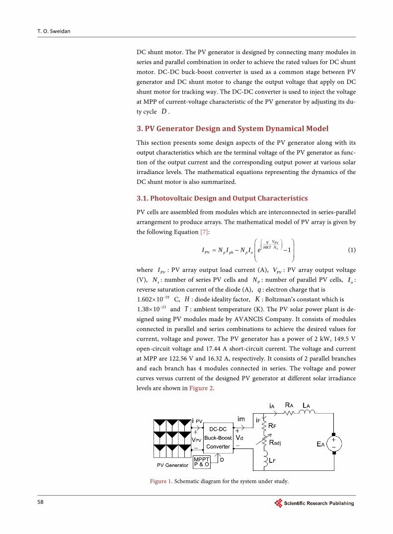
Figure 1 shows a schematic diagram for the stand-alone PV solar panels feeding
T. O. Sweidan
58
DC shunt motor. The PV generator is designed by connecting many modules in series and parallel combination in order to achieve the rated values for DC shunt motor. DC-DC buck-boost converter is used as a common stage between PV generator and DC shunt motor to change the output voltage that apply on DC shunt motor for tracking way. The DC-DC converter is used to inject the voltage at MPP of current-voltage characteristic of the PV generator by adjusting its du-ty cycle D .
3. PV Generator Design and System Dynamical Model
This section presents some design aspects of the PV generator along with its output characteristics which are the terminal voltage of the PV generator as func-tion of the output current and the corresponding output power at various solar irradiance levels. The mathematical equations representing the dynamics of the DC shunt motor is also summarized.
3.1. Photovoltaic Design and Output Characteristics
PV cells are assembled from modules which are interconnected in series-parallel arrangement to produce arrays. The mathematical model of PV array is given by the following Equation [7]:
1PV
s
VqHKT N
PV p ph p oI N I N I e
= − −
(1)
where PVI : PV array output load current (A), PVV : PV array output voltage (V), sN : number of series PV cells and PN : number of parallel PV cells, oI : reverse saturation current of the diode (A), q : electron charge that is
191.602 10−× C, H : diode ideality factor, K : Boltzman’s constant which is 231.38 10−× and T : ambient temperature (K). The PV solar power plant is de-
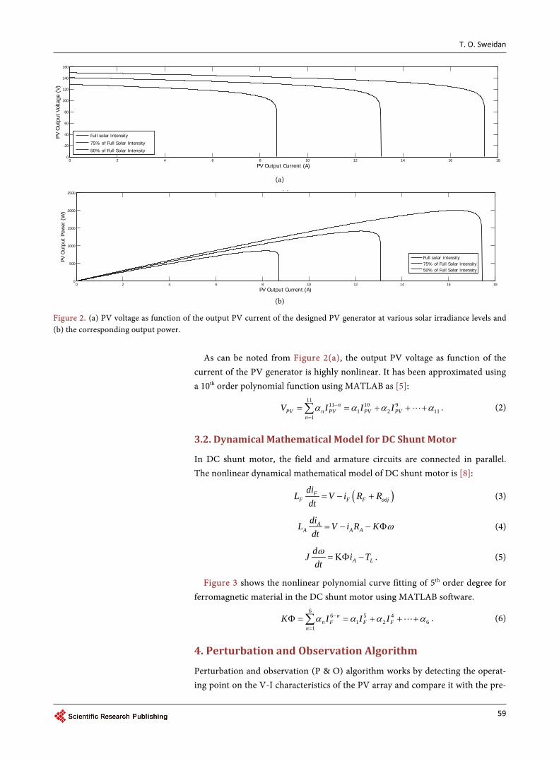
signed using PV modules made by AVANCIS Company. It consists of modules connected in parallel and series combinations to achieve the desired values for current, voltage and power. The PV generator has a power of 2 kW, 149.5 V open-circuit voltage and 17.44 A short-circuit current. The voltage and current at MPP are 122.56 V and 16.32 A, respectively. It consists of 2 parallel branches and each branch has 4 modules connected in series. The voltage and power curves versus current of the designed PV generator at different solar irradiance levels are shown in Figure 2.
Figure 1. Schematic diagram for the system under study.
T. O. Sweidan
59
(a)
(b)
Figure 2. (a) PV voltage as function of the output PV current of the designed PV generator at various solar irradiance levels and (b) the corresponding output power.
As can be noted from Figure 2(a), the output PV voltage as function of the
current of the PV generator is highly nonlinear. It has been approximated using a 10th order polynomial function using MATLAB as [5]:
1111 10 9
1 2 111
nPV n PV PV PV
nV I I Iα α α α−
=
= = + + +∑ . (2)
3.2. Dynamical Mathematical Model for DC Shunt Motor
In DC shunt motor, the field and armature circuits are connected in parallel. The nonlinear dynamical mathematical model of DC shunt motor is [8]:
( )FF F F adj
diL V i R Rdt
= − + (3)
AA A A
diL V i R Kdt
ω= − − Φ (4)
A LdJ i Tdtω= ΚΦ − . (5)
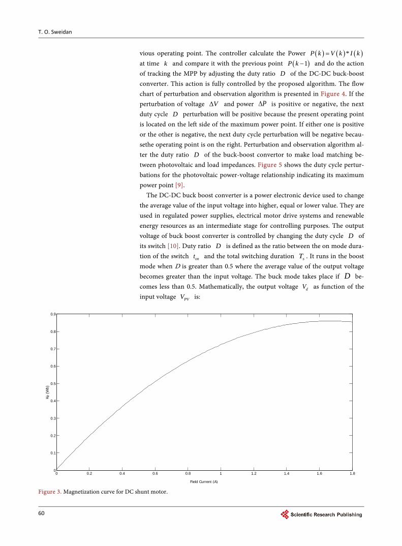
Figure 3 shows the nonlinear polynomial curve fitting of 5th order degree for ferromagnetic material in the DC shunt motor using MATLAB software.
66 5 4
1 2 61
nn F F F
nK I I Iα α α α−
=
Φ = = + + +∑ . (6)
4. Perturbation and Observation Algorithm
Perturbation and observation (P & O) algorithm works by detecting the operat-ing point on the V-I characteristics of the PV array and compare it with the pre-
0 2 4 6 8 10 12 14 16 180
20
40
60
80
100
120
140
160
PV Output Current (A)
PV O
utpu
t Vo
ltage
(V)
Full solar Intensity
75% of Full Solar Intensity
50% of Full Solar Intensity
0 2 4 6 8 10 12 14 16 180
500
1000
1500
2000
2500
PV Output Current (A)
PV O
utpu
t Po
wer
(W
)
( )
Full solar Intensity75% of Full Solar Intensity50% of Full Solar Intensity
T. O. Sweidan
60
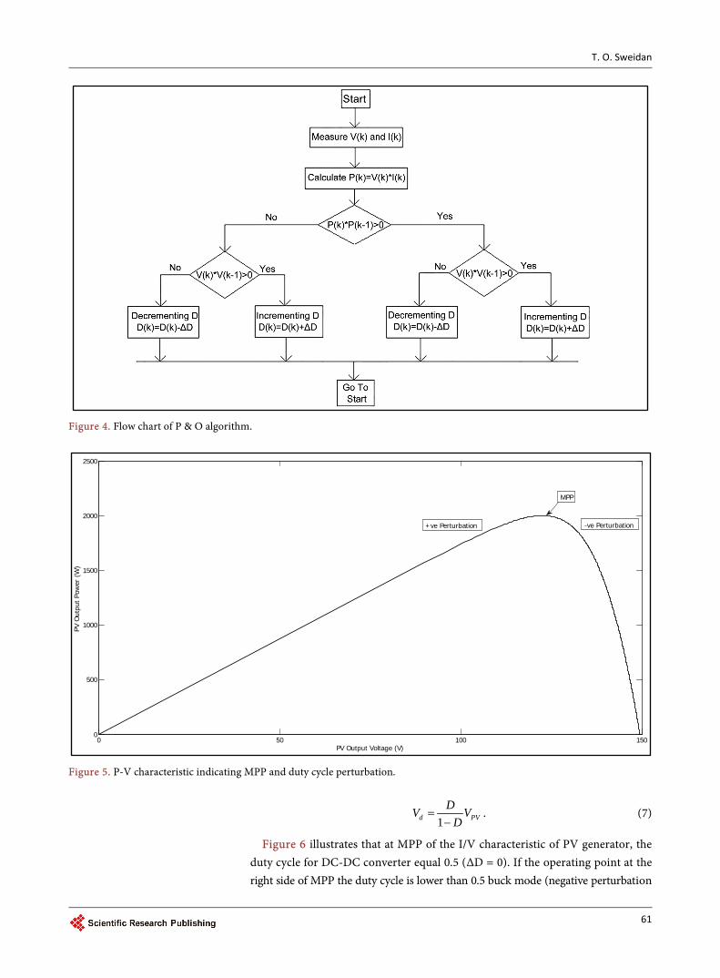
vious operating point. The controller calculate the Power ( ) ( ) ( )*P k V k I k= at time k and compare it with the previous point ( )1P k − and do the action of tracking the MPP by adjusting the duty ratio D of the DC-DC buck-boost converter. This action is fully controlled by the proposed algorithm. The flow chart of perturbation and observation algorithm is presented in Figure 4. If the perturbation of voltage V∆ and power P∆ is positive or negative, the next duty cycle D perturbation will be positive because the present operating point is located on the left side of the maximum power point. If either one is positive or the other is negative, the next duty cycle perturbation will be negative becau-sethe operating point is on the right. Perturbation and observation algorithm al-ter the duty ratio D of the buck-boost convertor to make load matching be-tween photovoltaic and load impedances. Figure 5 shows the duty cycle pertur-bations for the photovoltaic power-voltage relationship indicating its maximum power point [9].
The DC-DC buck boost converter is a power electronic device used to change the average value of the input voltage into higher, equal or lower value. They are used in regulated power supplies, electrical motor drive systems and renewable energy resources as an intermediate stage for controlling purposes. The output voltage of buck boost converter is controlled by changing the duty cycle D of its switch [10]. Duty ratio D is defined as the ratio between the on mode dura-tion of the switch ont and the total switching duration sT . It runs in the boost mode when D is greater than 0.5 where the average value of the output voltage becomes greater than the input voltage. The buck mode takes place if D be-comes less than 0.5. Mathematically, the output voltage dV as function of the input voltage PVV is:
Figure 3. Magnetization curve for DC shunt motor.
0 0.2 0.4 0.6 0.8 1 1.2 1.4 1.6 1.80
0.1
0.2
0.3
0.4
0.5
0.6
0.7
0.8
0.9
Field Current (A)
Kφ (
Wb)
T. O. Sweidan
61
Figure 4. Flow chart of P & O algorithm.
Figure 5. P-V characteristic indicating MPP and duty cycle perturbation.
1d PVDV V
D=
−. (7)
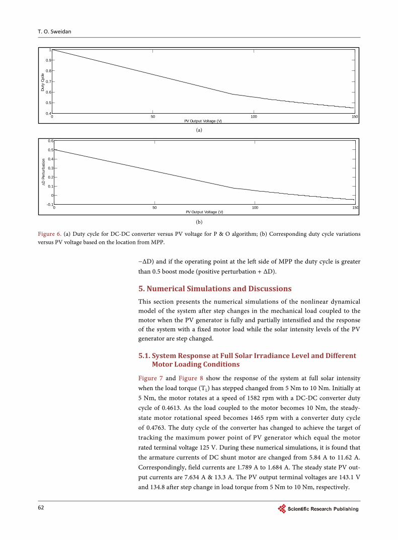
Figure 6 illustrates that at MPP of the I/V characteristic of PV generator, the duty cycle for DC-DC converter equal 0.5 (∆D = 0). If the operating point at the right side of MPP the duty cycle is lower than 0.5 buck mode (negative perturbation
0 50 100 1500
500
1000
1500
2000
2500
PV Output Voltage (V)
PV O
utpu
t Po
wer
(W
)
MPP
+ve Perturbation -ve Perturbation
T. O. Sweidan
62
(a)
(b)
Figure 6. (a) Duty cycle for DC-DC converter versus PV voltage for P & O algorithm; (b) Corresponding duty cycle variations versus PV voltage based on the location from MPP.
−∆D) and if the operating point at the left side of MPP the duty cycle is greater than 0.5 boost mode (positive perturbation + ∆D).
5. Numerical Simulations and Discussions This section presents the numerical simulations of the nonlinear dynamical model of the system after step changes in the mechanical load coupled to the motor when the PV generator is fully and partially intensified and the response of the system with a fixed motor load while the solar intensity levels of the PV generator are step changed.
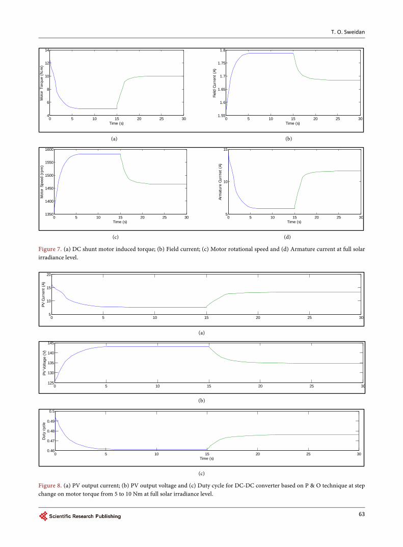
5.1. System Response at Full Solar Irradiance Level and Different Motor Loading Conditions
Figure 7 and Figure 8 show the response of the system at full solar intensity when the load torque (TL) has stepped changed from 5 Nm to 10 Nm. Initially at 5 Nm, the motor rotates at a speed of 1582 rpm with a DC-DC converter duty cycle of 0.4613. As the load coupled to the motor becomes 10 Nm, the steady- state motor rotational speed becomes 1465 rpm with a converter duty cycle of 0.4763. The duty cycle of the converter has changed to achieve the target of tracking the maximum power point of PV generator which equal the motor rated terminal voltage 125 V. During these numerical simulations, it is found that the armature currents of DC shunt motor are changed from 5.84 A to 11.62 A. Correspondingly, field currents are 1.789 A to 1.684 A. The steady state PV out-put currents are 7.634 A & 13.3 A. The PV output terminal voltages are 143.1 V and 134.8 after step change in load torque from 5 Nm to 10 Nm, respectively.
0 50 100 1500.4
0.5
0.6
0.7
0.8
0.9
1
PV Output Voltage (V)
Dut
y Cy
cle
0 50 100 150-0.1
0
0.1
0.2
0.3
0.4
0.5
0.6
PV Output Voltage (V)
∆D
Per
turb
atio
n
T. O. Sweidan
63
(a) (b)
(c) (d)
Figure 7. (a) DC shunt motor induced torque; (b) Field current; (c) Motor rotational speed and (d) Armature current at full solar irradiance level.
(a)
(b)
(c)
Figure 8. (a) PV output current; (b) PV output voltage and (c) Duty cycle for DC-DC converter based on P & O technique at step change on motor torque from 5 to 10 Nm at full solar irradiance level.
0 5 10 15 20 25 304
6
8
10
12
14
Time (s)
Mot
or T
orqu
e (N
.m)
0 5 10 15 20 25 301.55
1.6
1.65
1.7
1.75
1.8
Time (s)
Fiel
d Cu
rren
t (A
)
0 5 10 15 20 25 301350
1400
1450
1500
1550
1600
Time (s)
Mot
or S
peed
(rp
m)
0 5 10 15 20 25 305
10
15
Time (s)Ar
mat
ure
Curr
net
(A)
0 5 10 15 20 25 305
10
15
20
PV C
urre
nt (
A)
(b)
0 5 10 15 20 25 30125
130
135
140
145
PV V
olta
ge (
V)
0 5 10 15 20 25 300.46
0.47
0.48
0.49
0.5
Time (s)
Dut
y cy
cle
T. O. Sweidan
64
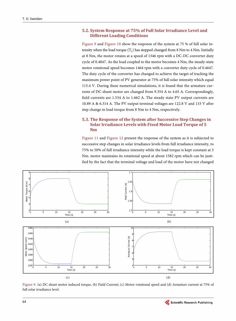
5.2. System Response at 75% of Full Solar Irradiance Level and Different Loading Conditions
Figure 9 and Figure 10 show the response of the system at 75 % of full solar in- tensity when the load torque (TL) has stepped changed from 8 Nm to 4 Nm. Initially at 8 Nm, the motor rotates at a speed of 1346 rpm with a DC-DC converter duty cycle of 0.4847. As the load coupled to the motor becomes 4 Nm, the steady-state motor rotational speed becomes 1464 rpm with a converter duty cycle of 0.4647. The duty cycle of the converter has changed to achieve the target of tracking the maximum power point of PV generator at 75% of full solar intensity which equal 115.4 V. During these numerical simulations, it is found that the armature cur-rents of DC shunt motor are changed from 9.354 A to 4.65 A. Correspondingly, field currents are 1.534 A to 1.662 A. The steady state PV output currents are 10.89 A & 6.314 A. The PV output terminal voltages are 122.8 V and 133 V after step change in load torque from 8 Nm to 4 Nm, respectively.
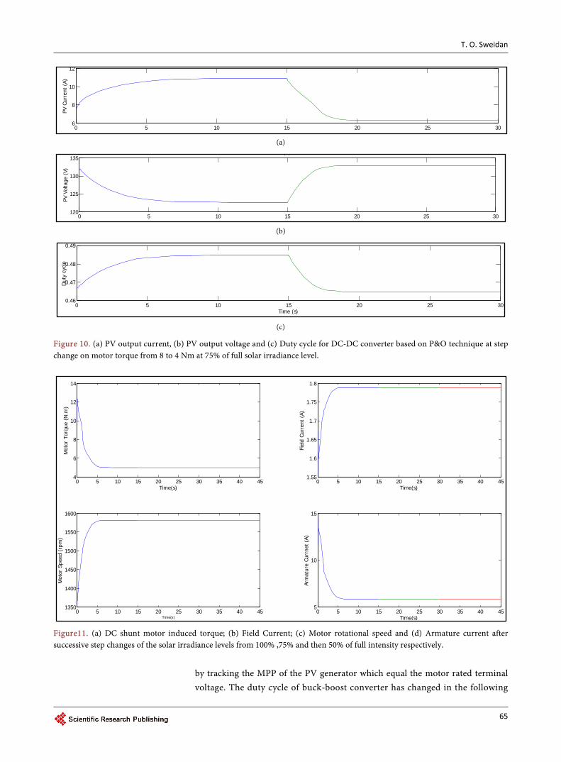
5.3. The Response of the System after Successive Step Changes in Solar Irradiance Levels with Fixed Motor Load Torque of 5 Nm
Figure 11 and Figure 12 present the response of the system as it is subjected to successive step changes in solar irradiance levels from full irradiance intensity, to 75% to 50% of full irradiance intensity while the load torque is kept constant at 5 Nm. motor maintains its rotational speed at about 1582 rpm which can be justi-fied by the fact that the terminal voltage and load of the motor have not changed
(a) (b)
(c) (d)
Figure 9. (a) DC shunt motor induced torque, (b) Field Current; (c) Motor rotational speed and (d) Armature current at 75% of full solar irradiance level.
0 5 10 15 20 25 303
4
5
6
7
8
9
Time (s)
Mot
or T
orqu
e (N
.m)
( )
0 5 10 15 20 25 301.5
1.55
1.6
1.65
1.7
Time (s)
Fiel
d Cu
rren
t (A
)
( )
0 5 10 15 20 25 301340
1360
1380
1400
1420
1440
1460
1480
Time (s)
Mot
or S
peed
(rp
m)
0 5 10 15 20 25 304
5
6
7
8
9
10
Time (s)
Arm
atur
e Cu
rrne
t (A
)
T. O. Sweidan
65
(a)
(b)
(c)
Figure 10. (a) PV output current, (b) PV output voltage and (c) Duty cycle for DC-DC converter based on P&O technique at step change on motor torque from 8 to 4 Nm at 75% of full solar irradiance level.
Figure11. (a) DC shunt motor induced torque; (b) Field Current; (c) Motor rotational speed and (d) Armature current after successive step changes of the solar irradiance levels from 100% ,75% and then 50% of full intensity respectively.
by tracking the MPP of the PV generator which equal the motor rated terminal voltage. The duty cycle of buck-boost converter has changed in the following
0 5 10 15 20 25 306
8
10
12PV
Cur
rent
(A)
0 5 10 15 20 25 30120
125
130
135
PV V
olta
ge (
V)
( )
0 5 10 15 20 25 300.46
0.47
0.48
0.49
Time (s)
Dut
y cy
cle
0 5 10 15 20 25 30 35 40 454
6
8
10
12
14
Time(s)
Mot
or T
orqu
e (N
.m)
0 5 10 15 20 25 30 35 40 451.55
1.6
1.65
1.7
1.75
1.8
Time(s)
Fiel
d Cu
rren
t (A
)
0 5 10 15 20 25 30 35 40 451350
1400
1450
1500
1550
1600
Time(s)
Mot
or S
peed
(rp
m)
0 5 10 15 20 25 30 35 40 455
10
15
Time(s)
Arm
atur
e Cu
rrne
t (A
)
T. O. Sweidan
66
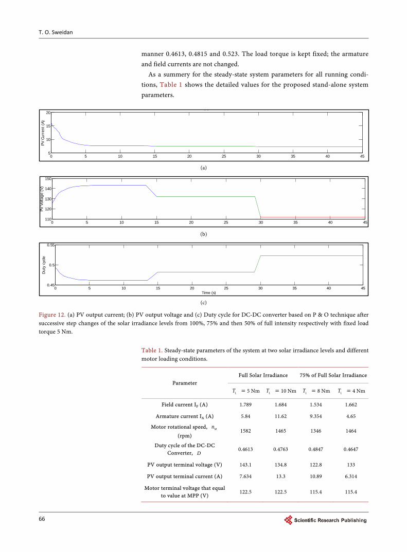
manner 0.4613, 0.4815 and 0.523. The load torque is kept fixed; the armature and field currents are not changed.
As a summery for the steady-state system parameters for all running condi-tions, Table 1 shows the detailed values for the proposed stand-alone system parameters.
(a)
(b)
(c)
Figure 12. (a) PV output current; (b) PV output voltage and (c) Duty cycle for DC-DC converter based on P & O technique after successive step changes of the solar irradiance levels from 100%, 75% and then 50% of full intensity respectively with fixed load torque 5 Nm.
Table 1. Steady-state parameters of the system at two solar irradiance levels and different motor loading conditions.
Parameter Full Solar Irradiance 75% of Full Solar Irradiance
LT = 5 Nm LT = 10 Nm LT = 8 Nm LT = 4 Nm
Field current IF (A) 1.789 1.684 1.534 1.662
Armature current IA (A) 5.84 11.62 9.354 4.65
Motor rotational speed, Mn (rpm)
1582 1465 1346 1464
Duty cycle of the DC-DC Converter, D
0.4613 0.4763 0.4847 0.4647
PV output terminal voltage (V) 143.1 134.8 122.8 133
PV output terminal current (A) 7.634 13.3 10.89 6.314
Motor terminal voltage that equal to value at MPP (V)
122.5 122.5 115.4 115.4
0 5 10 15 20 25 30 35 40 455
10
15
20
PV C
urre
nt (
A)
( )
0 5 10 15 20 25 30 35 40 45110
120
130
140
150
PV V
olta
ge (
V)
0 5 10 15 20 25 30 35 40 450.45
0.5
0.55
Time (s)
Dut
y cy
cle
T. O. Sweidan
67
6. Conclusion
The dynamical performance of a DC shunt motor fed from PV generator is in-vestigated. The PV generator is designed at full solar intensity to give the maxi-mum power at the motor rated conditions. The nonlinearity of the output cha-racteristics I/V of the photovoltaic generator at different solar irradiance levels is included in all simulations by polynomial curve fitting. The perturbation and observation algorithm is employed in the simulation to track the MPP of the PV generator by adjusting the duty cycle of the DC-DC converter. The study com-prises the response of DC shunt motor when after step changes in the load coupled with the motor at 100% and 75% of full solar irradiance level and after successive step changes in the solar intensity with constant motor loading condi-tions. It is concluded that P & O technique always changes the value of duty cycle of the DC-DC buck boost converter to track the MPP of the PV generator which is close to the motor rated voltage. Basically, as the mechanical load coupled to the motor increases, the rotational speed of the motor decreases and the armature current of the motor are increased too. As a general conclusion, the proposed PV generator can withstand step changes in the load coupled to the motor and step changes in the solar irradiance levels, which indicates the ro-bustness and proves the reliability of the integration between PV system and DC shunt motor.
References [1] Sweidan, T.O., Widyan, M.S. and Rifai, M.B. (2017) Perturbation and Observation
as MPPT for Highly Penetrated Grid-Integrated PV Generator Considering Sym-metrical Three-Phase Fault. International Journal of Power and Energy Conversion (in Press).
[2] Widyan, M.S., Al Tarabsheh, A.I., Etier, I.Y. and Hanitsch, R.E. (2010) Transient Analysis and Output Characteristics of DC Motors Fed by Photovoltaic Systems. Jordan Journal of Mechanical and Industrial Engineering, 4, 193-204.
[3] Mahmoud, H.A. and Nashed, M.N. (2016) Solar Powered PV Stand-alone Based DC Motor Drive Using Fuzzy Logic Control. International Journal of Engineering Re-search, 5, 420-424.
[4] Widyan, M.S., Harb, A.M. and Al-Oquili, O.M. (2014) Transient and Steady State Performance Analysis of Hybrid Powered DC Series Motor via DC Shunt and PV Generator with Maximum Power Point Tracking. Electrical Engineering, 96, 99- 107. https://doi.org/10.1007/s00202-013-0282-x
[5] Widyan, M.S. (2015) Modeling, Simulation and Operational Characteristics of a Stand-Alone Hybrid-Powered PMDC Motor for Pumping Application. Interna-tional Journal of Power and Energy Systems, 35, 1-13. https://doi.org/10.2316/Journal.203.2015.1.203-6064
[6] Sridhar, R., Dhar, S. and Dash, S. (2015) Performance Analysis of a Standalone PV System with Reduced Switch Cascaded Multilevel Inverter. International Journal of Power and Energy Conversion, 6, 107-127. https://doi.org/10.1504/IJPEC.2015.069428
[7] Patel, M.R. (1999) Wind and Solar Power System. CRC Press LLC, USA.
[8] Ong, C.-M. (1998) Dynamic Simulation of Electric Machinery. Prentice Hall PTR,
T. O. Sweidan
68
Upper Saddle River, New Jersey.
[9] Jain, S. and Agarwal, V. (2007) Comparison of the Performance of Maximum Pow-er Point Tracking Schemes Applied to Single-Stage Grid-Connected Photovoltaic Systems. IET Electric Power Applications, 1, 753-762. https://doi.org/10.1049/iet-epa:20060475
[10] Mohan, N., Undel, T.M. and Robbins, W.P. (2003) Power Electronics, Converters, Applications and Design. John Wiley & Sons, Inc., Chicago.
Appendix A
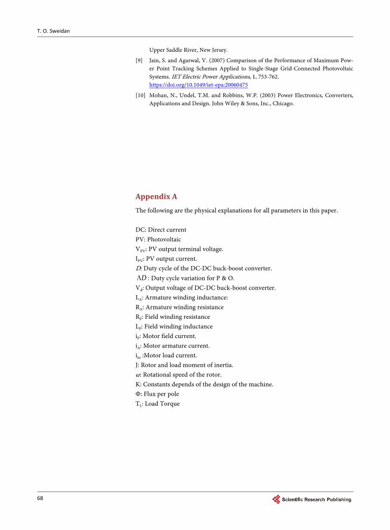
The following are the physical explanations for all parameters in this paper. DC: Direct current PV: Photovoltaic VPV: PV output terminal voltage. IPV: PV output current. D: Duty cycle of the DC-DC buck-boost converter.
DΛ : Duty cycle variation for P & O. Vd: Output voltage of DC-DC buck-boost converter. LA: Armature winding inductance: RA: Armature winding resistance RF: Field winding resistance LF: Field winding inductance iF: Motor field current. iA: Motor armature current. im :Motor load current. J: Rotor and load moment of inertia. ω: Rotational speed of the rotor. K: Constants depends of the design of the machine. Φ: Flux per pole TL: Load Torque
T. O. Sweidan
69
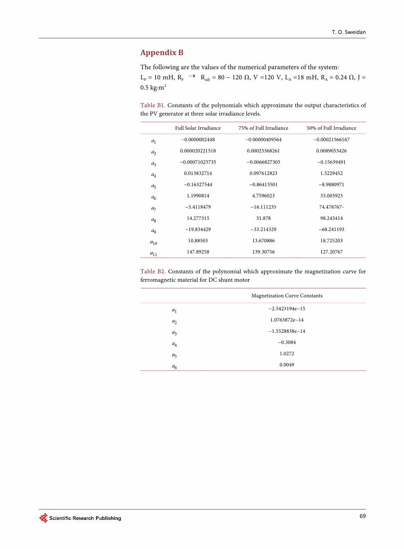
Appendix B
The following are the values of the numerical parameters of the system: LF = 10 mH, RF → Radj = 80 − 120 Ω, V =120 V, LA =18 mH, RA = 0.24 Ω, J = 0.5 kg·m2
Table B1. Constants of the polynomials which approximate the output characteristics of the PV generator at three solar irradiance levels.
Full Solar Irradiance 75% of Full Irradiance 50% of Full Irradiance
α1 −0.0000002448 −0.00000409564 −0.00021566167
α2 0.000020221518 0.00025368261 0.0089053426
α3 −0.00071025735 −0.0066827305 −0.15639491
α4 0.013832714 0.097612823 1.5229452
α5 −0.16327544 −0.86413501 −8.9880971
α6 1.1990814 4.7596023 33.003923
α7 −5.4118479 −16.111235 74.478767-
α8 14.277315 31.878 98.243414
α9 −19.834429 −33.214329 −68.241193
α10 10.88503 13.670886 18.725203
α11 147.89258 139.30756 127.20767
Table B2. Constants of the polynomial which approximate the magnetization curve for ferromagnetic material for DC shunt motor
Magnetization Curve Constants
α1 −2.5423194e−15
α2 1.0763872e−14
α3 −1.5528838e−14
α4 −0.3084
α5 1.0272
α6 0.0049

Submit or recommend next manuscript to SCIRP and we will provide best service for you:
Accepting pre-submission inquiries through Email, Facebook, LinkedIn, Twitter, etc. A wide selection of journals (inclusive of 9 subjects, more than 200 journals) Providing 24-hour high-quality service User-friendly online submission system Fair and swift peer-review system Efficient typesetting and proofreading procedure Display of the result of downloads and visits, as well as the number of cited articles Maximum dissemination of your research work
Submit your manuscript at: http://papersubmission.scirp.org/ Or contact [email protected]