Embed Size (px)
Citation preview

Dynamic Visualization of Complex Systems:Extending the Impact of Model Based Systems Engineering
Troy A. Peterson
Fellow & Chief Engineer
Booz Allen Hamilton
NDIA 18th Annual Systems Engineering Conference
October 26-29, 2015

Copyright © 2015 by Troy Peterson. Published and used by NDIA with permission.
Complexity in Systems
• System of Systems
• Collaborating Systems
• Mechatronic Systems
• Embedded Systems
• Cyber Physical Systems
– Complexity, Ambiguity, Creativity, Emergent,
– Autonomous, Self-Aware,
Third level (Arial 16 pt)
o Fourth level (Arial 16 pt)
» Fifth level (Arial 16 pt)
1
Copyright © 2015 by Troy Peterson. Published and used by NDIA with permission.
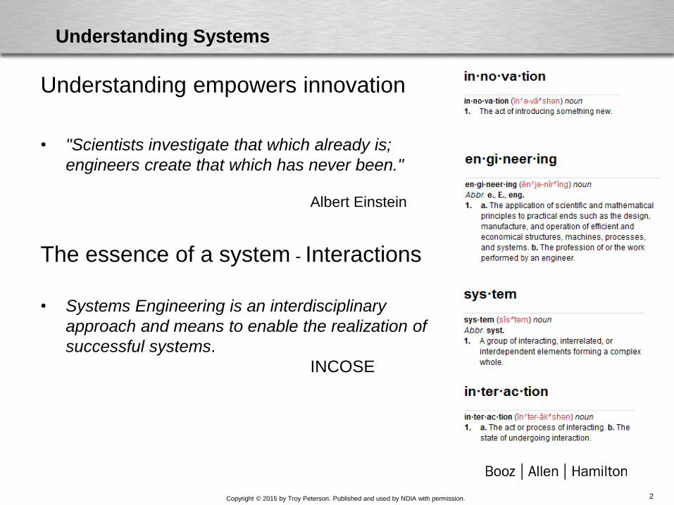
Understanding Systems
Understanding empowers innovation
• "Scientists investigate that which already is;
engineers create that which has never been."
Albert Einstein
The essence of a system - Interactions
• Systems Engineering is an interdisciplinary
approach and means to enable the realization of
successful systems.
INCOSE
2

Copyright © 2015 by Troy Peterson. Published and used by INCOSE with permission.
Expanding System Domain Boundary Increasing Interactions
Increased Density of System External Elements & InteractionsIncreased Interactions Between External Elements
Increased Density of System Elements & Interactions
System External Elements & Interactions
System Elements & Interactions
Interactions Complexity
Interaction Density
3

Copyright © 2015 by Troy Peterson. Published and used by NDIA with permission.
Internet of Things
4

Copyright © 2015 by Troy Peterson. Published and used by NDIA with permission.
Complexity – Is this all new?
“Today more and more design problems are reaching
insoluble levels of complexity.”
“At the same time that problems increase in quantity,
complexity and difficulty, they also change faster than
before.”
1. Christopher Alexander, “Notes on the Synthesis of Form” Harvard University Press, Cambridge Massachusetts, 1964
Christopher Alexander,
Notes on the Synthesis of Form1,
“Trial-and-error design is an admirable method. But it is
just real world trial and error which we are trying to replace
by a symbolic method. Because trial and error is too
expensive and too slow.”
5

Copyright © 2015 by Troy Peterson. Published and used by NDIA with permission.
Rethinking System Conceptualization
• Interconnectedness and the rise of Cyber Physical Systems
• The National Science Foundation (NSF) describes Cyber-Physical
Systems (CPS) as “engineered systems that are built from, and
depend upon, the seamless integration of computational algorithms
and physical components”
• They tightly intertwine computational elements with physical
entities across domains
• The rapid increase in Cyber-Physical Systems is changing the way
we develop, manage and interact with systems.
• The NSF notes that CPS challenges and opportunities are both
significant and far-reaching. To address these challenges the NSF
is calling for methods to conceptualize and design for the deep
interdependencies inherent in Cyber-Physical Systems.
6

Copyright © 2015 by Troy Peterson. Published and used by NDIA with permission.
Systems Engineering Transformation
• While complex systems transform the landscape, the Systems
Engineering discipline is also experiencing a transformation - to a
model-based discipline.
• While Model Based Systems Engineering (MBSE) shows significant
promise, it’s still in a formative stage and very few subject matter
experts understand formalized systems languages or have ready
access to MBSE related tools.
• Key enablers to managing system complexity
–Applying MBSE to provide explicit integrated system models
–Expressing system models to deepen our understanding
–Leverage methods to reach the larger community of stakeholders
7

Copyright © 2015 by Troy Peterson. Published and used by NDIA with permission.
Model Based Systems Engineering
• Model Based Systems Engineering (MBSE) provides organizations a
timely opportunity to address the rapid growth in complexity
• INCOSE defines Model-Based Systems Engineering (MBSE) as “the
formalized application of modeling to support system requirements,
design, analysis, verification and validation activities beginning in the
conceptual design phase and continuing throughout development and later
life cycle phases…” INCOSE SE Vision 2020
• The Object Management Group’s MBSE wiki notes that “Modeling has
always been an important part of systems engineering to support
functional, performance, and other types of engineering analysis.”
• The application of MBSE has increased dramatically in recent years
enabled by the continued maturity of modeling languages such as SysML
and significant advancements made by tools vendors
8

Copyright © 2015 by Troy Peterson. Published and used by NDIA with permission.
Model Based Systems Engineering
•MBSE is often discussed as being composed of three
fundamental elements – tool, language and method.
–While there are differences between tools most are very capable and
can be used to make significant improvements in managing the
complexity of systems today.
–Many modeling languages also exist to express system
representations. MBSE practitioners often use the System Modeling
Language (SysML).
–The third element, method, has not always been given proper
consideration, because the language and tool are relatively method
independent, it is methodology which further differentiates the
effectiveness of any MBSE approach.
Content – Process – Automation
9

Copyright © 2015 by Troy Peterson. Published and used by NDIA with permission.
MBSE: Pattern Based Systems Engineering
• As a Model-Based Systems Engineering (MBSE) methodology,
Pattern-Based Systems Engineering (PBSE) is tool and language
neutral and offers a strong underlying ontology and metamodel.
• At the heart of the PBSE metamodel is a focus on interactions
which are also at the heart of complex systems and the basis of the
physical sciences.
• PBSE can address 10:1 more complex systems with 10:1 reduction
in modeling effort, using people from a 10:1 larger community than
the “systems expert” group, producing more consistent and
complete models sooner. These dramatic gains are possible
because projects using PBSE get a “learning curve jumpstart” from
an existing pattern
10

Copyright © 2015 by Troy Peterson. Published and used by NDIA with permission.
MBSE: Pattern Based Systems Engineering
• PBSE is leveraged as the MBSE methodology due to the impact it has had in
helping teams focus on interactions, improve platform management as well as its
data compression characteristics and strong underlying metamodel. To increase
awareness of the PBSE approach, INCOSE has recently started a Patterns
Challenge Team within the INCOSE MBSE Initiative and it is a recognized
methodology on INCOSE’s MBSE wiki.
INCOSE PBSE Content: http://www.omgwiki.org/MBSE/doku.php?id=mbse:patterns:patterns
A summary view of the S* metamodel and Pattern Hierarchy and Process
11

Copyright © 2015 by Troy Peterson. Published and used by NDIA with permission.
Model Expression
• The Systems Modeling Language (SysML) has proven to be a
significant enabler to advance MBSE methods given its flexibility
and expressiveness.
• The flexibility of the language and advances in tools also permits
easy construction of allocation tables and dynamic tabular
representations.
• While SysML provides clarity and consistency, unfortunately, the
number of people who know and SysML is still relatively small
which has led to some criticism and limited widespread
acceptance.
• To bring the full power of MBSE to the larger community system
models in SysML can also be represented in a more intuitive form.
Not as a replacement to the rich detail provided by the SysML but
as a complementary product to conceptualize and design for the
deep inter-dependencies inherent in systems today.
12

Copyright © 2015 by Troy Peterson. Published and used by NDIA with permission.
Model Expression and Learning
• The objective of model expression is to maximize our ability to
translate system data and information into knowledge we can use
to improve the trajectory of our programs.
• To improve program and system performance we need to deepen
the understanding of system models for the larger community of
development stakeholders.
• To ensure we can extend the power of MBSE and SysML to a
much larger community it’s worthwhile to first consider how we
think and interact with information.
– “Vision trumps all other senses. We are incredible at remembering pictures.” 8
– Research has shown repeatedly that we are wonderful at encoding images but
not especially good with arbitrary information
– Our brains are designed for spatial information and our image recognition is very
durable.
13

Copyright © 2015 by Troy Peterson. Published and used by NDIA with permission.
Exercise
Pretend your life depends upon remembering the sequence of numbers I am
about to share with you
– Do not write them down
– Your results will not be scored
– Everyone passes
Each number will be displayed in a green circle.
Please commit to memory the numbers which follow
#
14

24

Write down as many as
you can remember

How well did you do?

Let’s try another view

3
2
5
20
24
25
1
4
16
2122
6

Any better?

One last try?

1 2 3 4 5
6 7 8 9 10
11 12 13 14 15
16 17 18 19 20
21 22 23 24 25

Could you reproduce the numbers now?
How would you do it?
Do you think of the numbers or the pattern?

Copyright © 2015 by Troy Peterson. Published and used by NDIA with permission.
Information Encoding and Allocations
• Just as a computer needs information coded properly in bits –
we need images.
• Long strings of numbers are very easy for a computer to recall
but spatial information and associations can be far more
challenging for a computer. This is true even with the great
strides made in machine learning and artificial intelligence.
• As our developments become more digital we need to
appropriately allocate activities.
–Let machines handle what they do well, for instance, storing
and reproducing information
–Focus our attention on leveraging our amazing cognitive ability
to compare, contrast, associate, integrate and synthesize
information
24

Copyright © 2015 by Troy Peterson. Published and used by NDIA with permission.
Model Expression
• Use of different representations of the same information is not a
new concept. Architects, engineers and others often provide
multiple views of the same elements to provide users of their
products as much clarity as possible.
• To represent form engineers often use left, right, top, bottom,
exploded, isometric, cut-out and perspective drawings.
• To represent function we also use several views; this notion is a
key tenant of SysML, UML, DODAF and other languages and
frameworks.
• In particular, SysML defines nine diagrams, all of which are useful
and depict important information about the structure and behavior
of a system.
25

Copyright © 2015 by Troy Peterson. Published and used by NDIA with permission.
Perspective matters
Different views communicate different things
Some views can tell us interesting things very quickly
Exercise: Can you name this system?
26

Copyright © 2015 by Troy Peterson. Published and used by NDIA with permission.
The Larger Stakeholder Community
• Many SMEs are required to engineer systems.
• Each SME has tools, languages and methods that they use to model and
design systems.
• These languages are often not natural or intuitive to others outside their
domain.
• We need to have representations which bridge over roles, domains and
areas of functional expertise.
• Graph Theory can provide a means to reach this larger community without
significantly sacrificing the power and expressivity of SysML’s semantics.
• It can also expose us to new ways of viewing, analyzing and
understanding the complex systems we design. Coupled with dynamic
visualization we can explore, query and learn the model
27
Copyright © 2015 by Troy Peterson. Published and used by NDIA with permission.
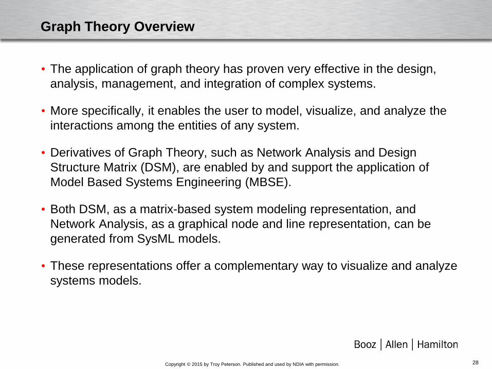
Graph Theory Overview
• The application of graph theory has proven very effective in the design,
analysis, management, and integration of complex systems.
• More specifically, it enables the user to model, visualize, and analyze the
interactions among the entities of any system.
• Derivatives of Graph Theory, such as Network Analysis and Design
Structure Matrix (DSM), are enabled by and support the application of
Model Based Systems Engineering (MBSE).
• Both DSM, as a matrix-based system modeling representation, and
Network Analysis, as a graphical node and line representation, can be
generated from SysML models.
• These representations offer a complementary way to visualize and analyze
systems models.
28

Copyright © 2015 by Troy Peterson. Published and used by NDIA with permission.
X’s indicate connectivity between elements
Network View Matrix ViewLines indicate connectivity between elements
A
B
C
D F
H
G
E
A B C D E F G H
A X
B X X X
C X X X X X
D X X X
E X X
F X X X X X
G X X X
H X
A powerful paradigm and method to analyze systems
• The diagrams below provide two different views of a generic system with relationships as shown
• For systems, relationships may be interactions of force, information, energy or mass flow
• These diagrams can be powerful in providing understanding of how systems elements interact
The network view is intuitive and good for understanding very large data sets
The matrix view provides a compact visual and enables holistic systems modeling
Graph Theory - Networks and Matrices
29

Copyright © 2015 by Troy Peterson. Published and used by NDIA with permission.
Leve
l 3 N
ames
1 2 3 4 5 6 8 9 10
11
12
13
14
15
16
17
18
20
21
22
23
24
25
26
27
28
29
30
31
32
34
35
36
37
38
39
40
41
42
43
44
45
Level 3 Names 1
2
3
4
5
6
8
9
10
11
12
13
14
15
16
17
18
20
21
22
23
24
25
26
27
28
29
30
31
32
34
35
36
37
38
39
40
41
42
43
44
45
Leve
l 2Le
vel 2
Leve
l1 D
om
ain C
Leve
l 2Le
vel 2
Leve
l 2Le
vel 2
.
Leve
l 1 D
om
ain B
$root
Leve
l 1 D
om
ain A
MDMDomains A, B & C
DSMDomain B
M x M
DSMDomain C
P x P
DMMDomains A & B
A x B
DMM DMM
Design Structure Matrix (DSM)• Square matrix- N x N or N2
• Analyze dependencies within a domain
• Used for products, process and Organizations
• Binary marks “(1” or “X”) show existence of a
relation
• Numerical entries are weights of relation
strength
• Can be directed or undirected (symmetrical)
Multi Domain Matrix (MDM)• Square matrix - N x N or N2
• Analyze dependencies across domain
• Combination of DSMs and DMMs
• Especially helpful for DSMs > 1000 elements
Domain Mapping Matrix (DMM)• Normally rectangular matrix – N x M
• Mapping between two domains
DSMN x N
N
N
B
C
A
B CA
DSMDomain A
N x N
Design Structure Matrix Overview
30

Copyright © 2015 by Troy Peterson. Published and used by NDIA with permission.
Nodes or
Vertices
Lines or
Edges
Network
Graph or
System
Graph
Network
System
Nodes and
Lines have
propertiesB
A
C
D
Undirected
Edge
Directed
Edge
Source
Node
Target
Node
Graph / Network Overview
31

Copyright © 2015 by Troy Peterson. Published and used by NDIA with permission.
Graph and DSM Patterns
• Non symmetrical
• Layered System – every system uses
or feeds every system below it
• Symmetrical
• Layered System – Every system uses
and feeds element 10
• Symmetrical
• Overlapping clusters
• Symmetrical
• Non-Overlapping clusters
Layout: Concentric Layout: Circular
Layout: ForceAtlas2 Layout: Yifan Hu
32

Copyright © 2015 by Troy Peterson. Published and used by NDIA with permission.
Graph and DSM Patterns and Algorithms
Network Graph
• Randomly generated
DSM
• Randomly ordered
Network Graph
• Nodes sized by degree
• Arranged by cluster
DSM
• Layered
• Change propagator, Element J, clearly shown at the bottom
• Clustered, showing both overlapping non-overlapping and clusters
Unorganized
Organized
33
Copyright © 2015 by Troy Peterson. Published and used by NDIA with permission.
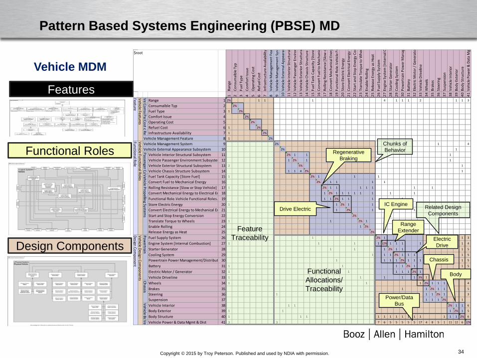
Pattern Based Systems Engineering (PBSE) MD
Ran
ge
Co
nsu
mal
ble
Typ
Fuel
Typ
e
Co
mfo
rt Is
sue
Op
erat
ing
Co
st
Ref
uel
Co
st
Infr
astr
uct
ure
Ava
ilab
ility
Veh
icle
Man
agem
ent
Feat
ure
Veh
icle
Man
agem
ent
Syst
em
Veh
icle
Ext
ern
al A
pp
eara
nce
Su
bsy
stem
Veh
icle
Inte
rio
r St
ruct
ura
l Su
bsy
stem
Veh
icle
Pas
sen
ger
Envi
ron
men
t Su
bsy
stem
Veh
icle
Ext
erio
r St
ruct
ura
l Su
bsy
stem
Veh
icle
Ch
assi
s St
ruct
ure
Su
bsy
stem
Fuel
Tan
k C
apac
ity
[Sto
re F
uel
]
Co
nve
rt F
uel
to
Mec
han
ical
En
ergy
Ro
llin
g R
esis
tan
ce [
Slo
w o
r St
op
Veh
icle
]
Co
nve
rt M
ech
anic
al E
ner
gy t
o E
lect
rica
l En
ergy
Fun
ctio
nal
Ro
le.V
ehic
le F
un
ctio
nal
Ro
les.
Veh
icle
Pro
pu
lsio
n S
ub
syst
em.F
low
En
ergy
[C
on
tro
l En
ergy
Flo
w]
Sto
re E
lect
ric
Ener
gy
Co
nve
rt E
lect
rica
l En
ergy
to
Mec
han
ical
En
ergy
Star
t an
d S
top
En
ergy
Co
nve
rsio
n
Tran
slat
e To
rqu
e to
Wh
eels
Enab
le R
olli
ng
Rel
ease
En
ergy
as
Hea
t
Fuel
Su
pp
ly S
yste
m
Engi
ne
Syst
em [
Inte
rnal
Co
mb
ust
ion
]
Star
ter
Gen
erat
or
Co
olin
g Sy
stem
Po
wer
trai
n P
ow
er M
anag
emen
t/D
istr
ibu
tio
n S
yste
m
Bat
tery
Elec
tric
Mo
tor
/ G
ener
ato
r
Veh
icle
Dri
velin
e
Wh
eels
Bra
kes
Stee
rin
g
Susp
ensi
on
Veh
icle
Inte
rio
r
Bo
dy
Exte
rio
r
Bo
dy
Stru
ctu
re
Veh
icle
Po
wer
& D
ata
Mgm
t &
Dis
t
1 2 3 4 5 6 7 8 9 10
11
12
13
14
15
16
17
18
19
20
21
22
23
24
25
26
27
28
29
30
31
32
33
34
35
36
37
38
39
40
41
1 2% 1 1 1 4 1 1 1 2 1 1 3
2 2%
3 1 2%
4 2%
5 2%
6 1 2%
7 1 2%
8 1 2%
9 2% 1 4
10 2% 1
11 2% 1 1 1
12 1 2% 1 1
13 2 5% 1
14 1 1 4 2% 1
15 1 2% 1 1 1
16 2% 1 1 1 1
17 1 2% 1 1 1 1 1 1 1
18 1 2% 1 1 1 1 1 1 1 1
19 1 1 2% 1 1 1 1
20 1 1 2% 1 1 1
21 1 2% 1 1
22 2% 1
23 1 1 2% 1 1
24 1 2%
25 2% 1
26 1 2% 1 1 3
27 1 1 1 1 12% 1 1 1 1 1 4
28 1 1 1 2% 1 1 1 5
29 1 1 1 2% 1 1 1 1 5
30 1 1 1 1 2% 1 1 1 1 1 5
31 1 1 1 1 2% 1 1 5
32 1 1 1 1 1 1 1 2% 1 1 5
33 1 1 1 1 1 3% 1 1 5
34 1 1 1 2% 1 1 1 4
35 1 1 1 2% 1 1 5
36 1 1 1 2% 1 3
37 1 1 1 2% 1
38 1 1 2% 1 1 6
39 1 1 1 2% 1 5
40 1 1 1 1 1 1 1 1 1 1 1 1 1 1 2% 6
41 3 3 7 6 5 5 5 5 5 17 4 8 5 1 11 12 6 12%
Veh
icle Bo
dy
Vehicle Interior
Body Exterior
Body Structure
Veh
icle Electrical System
Vehicle Power & Data Mgmt & Dist
Design
Co
mp
on
ent
Veh
icle Design
Co
mp
on
ents
Po
wertrain
Fuel Supply System
Engine System [Internal Combustion]
Starter Generator
Cooling System
Powertrain Power Management/Distribution System
Battery
Electric Motor / Generator
Vehicle Driveline
Ch
assis
Wheels
Brakes
Steering
Suspension
Convert Electrical Energy to Mechanical Energy
Start and Stop Energy Conversion
Translate Torque to Wheels
Enable Rolling
Release Energy as Heat
Fun
ction
al Ro
leV
ehicle Fu
nctio
nal R
oles
Vehicle Management System
Vehicle External Appearance SubsystemPassen
ger Carryin
g
Vehicle Interior Structural Subsystem
Vehicle Passenger Environment Subsystem
Vehicle Exterior Structural Subsystem
Vehicle Chassis Structure SubsystemVeh
icle Pro
pellin
g Systems
Fuel Tank Capacity [Store Fuel]
Convert Fuel to Mechanical Energy
Rolling Resistance [Slow or Stop Vehicle]
Convert Mechanical Energy to Electrical Energy
Functional Role.Vehicle Functional Roles.Vehicle Propulsion Subsystem.Flow Energy [Control Energy Flow]
Store Electric Energy
$root
Feature
Veh
icle Features
Veh
icle Perfo
rman
ce Feature
RangeCo
msu
mab
les Co
mp
atibility Featu
re
Consumalble Typ
Fuel TypePassen
ger Co
mfo
rt Feature G
rou
p
Comfort IssueCo
st of O
peratio
n Featu
re
Operating Cost
Refuel CostReliab
ility & A
vailability Featu
re
Infrastructure Availability
Vehicle Management Feature
Regenerative
Braking
Electric
Drive
Range
Extender
Power/Data
Bus
Features
Functional Roles
Design Components
IC Engine
Chassis
Body
Chunks of
Behavior
Vehicle MDM
Related Design
Components
Feature
Traceability
Functional
Allocations/
Traceability
Drive Electric
34

Copyright © 2015 by Troy Peterson. Published and used by NDIA with permission.
Power Pack Element A Element B Element C Element D Element E
Element H Element I Element JElement F Element G
Use MBSE system
descriptive models to
generate DSM and Graph
views
Dependency Kind• Mass Flow (5%)
• Force (24%)
• Energy (26%)
• Data (45%)
Model Expressed in SysML, DSM and Graph
35

Copyright © 2015 by Troy Peterson. Published and used by NDIA with permission.
Dynamic Visualization - Network
36

Copyright © 2015 by Troy Peterson. Published and used by NDIA with permission.
Conclusions
• As systems become more and more complex they provide both
incredible opportunity and risk.
• The benefits of Model Based Systems Engineering approaches are
a powerful way to model, understand and manage the evolution of
systems.
• Translating detailed models into simple system representations
(graphs and matrices) and providing dynamic visualizations can
extend the full power of model based methods to the larger
engineering community and deepen our understanding
• When coupled with an understanding of how we learn models have
an excellent opportunity to help development teams and leadership
gain insights, build intuition and speed the innovation
37

Copyright © 2015 by Troy Peterson. Published and used by NDIA with permission.
Troy Peterson Bio
Troy Peterson is a Booz Allen Fellow and Chief Engineer instituting capabilities to manage
complexity, engineer resiliency and speed innovation. As a Fellow, Troy operates as a firm-wide
resource to help colleagues and clients confront systems challenges.
Troy has led several international projects and large teams in the delivery of complex systems.
His experience spans commercial, government and academic environments across all product life
cycle phases. Recent engagements include Contingency Basing, the Ground Combat Vehicle
(GCV), Mine Resistant Ambush Protected (MRAP) vehicle and developing engineering capability
within organizations responsible for research, development, acquisition and system of systems
engineering and integration.
Troy’s impact has led to his appointment to six different boards to improve engineering education
and method application. He frequently speaks at leading engineering conferences and was
recently appointed by INCOSE as the lead for transforming Systems Engineering to model based
discipline.
Prior to joining Booz Allen, Troy worked at Ford Motor Company and as an entrepreneur
operating a design and management consulting business. Troy received his B.S. in Mechanical
Engineering from Michigan State University, his M.S. in Technology Management from
Rensselaer Polytechnic Institute, and an advanced graduate certificate in Systems Design and
Management from the Massachusetts Institute of Technology (MIT). He holds INCOSE Systems
Engineering, PMI Project Management, and ASQ Six Sigma Black Belt certifications.
Troy PetersonBooz Allen Fellow
Chief Engineer
313.806.3929
38

Copyright © 2015 by Troy Peterson. Published and used by NDIA with permission.
Abstract
Understanding Systems through Graph Theory and Dynamic Visualization
As today’s Cyber Physical Systems (CPS) become more and more complex they
provide both incredible opportunity and risk. In fact, rapidly growing complexity is a
significant impediment to the successful development, integration, and innovation of
systems. Over the years, methods to manage system complexity have taken many
forms. Model Based Systems Engineering (MBSE) provides organizations a timely
opportunity to address the complexities of Cyber Physical Systems. MBSE tools,
languages and methods are having a very positive impact but are still in a formative
stage and continue to evolve. Moreover, the Systems Modeling Language (SysML)
has proven to be a significant enabler to advance MBSE methods given its flexibility
and expressiveness. While the strengths of SysML provide clarity and consistency,
unfortunately the number of people who know SysML well is relatively small. To bring
the full power of MBSE to the larger community, system models represented in
SysML can be rendered in a more intuitive form. More specifically, Graph Theory has
proven to be very effective in the design, analysis, management, and integration of
complex systems. Network Analysis and Design Structure Matrix, both variants of
Graph Theory, enable users to model, visualize, and analyze the interactions among
the entities of any system. Use of MBSE and Graph Theory together to create
dynamic visualization can help teams gain insights, build intuition and ultimately help
speed the innovation process.
39

Copyright © 2015 by Troy Peterson. Published and used by NDIA with permission.
References
1. INCOSE Vision 2020
2.http://www.omgwiki.org/MBSE/doku.php?id=start
3.http://www.omgsysml.org/
4.W. Schindel, and V. Smith, “Results of Applying a Families-of-Systems Approach to Systems
Engineering of Product Line Families”, SAE International, Technical Report 2002-01-3086
(2002).
5.J. Bradley, M. Hughes, and W. Schindel, “Optimizing Delivery of Global Pharmaceutical
Packaging Solutions, Using Systems Engineering Patterns”, in Proc. of the INCOSE 2010
International Symposium (2010).
6.W. Schindel, “Integrating Materials, Process & Product Portfolios: Lessons from Pattern-Based
Systems Engineering”, in Proc. of 2012 Conference of Society for the Advancement of Material
and Process Engineering, 2012.
7.http://www.omgwiki.org/MBSE/doku.php?id=mbse:patterns:patterns
8.http://theweek.com/articles/460769/12-things-know-about-how-brain-works
9.Vishton, Peter M., Scientific Secrets for a Powerful Memory, The Great Courses, Course No
1965, 2012
10.Meadows, Donella, “Thinking in Systems – A Primer”, Chelsea Green Publishing, 2008
40

Copyright © 2015 by Troy Peterson. Published and used by NDIA with permission.
References
1. INCOSE Vision 2020
2.http://www.omgwiki.org/MBSE/doku.php?id=start
3.http://www.omgsysml.org/
4.W. Schindel, and V. Smith, “Results of Applying a Families-of-Systems Approach to Systems
Engineering of Product Line Families”, SAE International, Technical Report 2002-01-3086
(2002).
5.J. Bradley, M. Hughes, and W. Schindel, “Optimizing Delivery of Global Pharmaceutical
Packaging Solutions, Using Systems Engineering Patterns”, in Proc. of the INCOSE 2010
International Symposium (2010).
6.W. Schindel, “Integrating Materials, Process & Product Portfolios: Lessons from Pattern-Based
Systems Engineering”, in Proc. of 2012 Conference of Society for the Advancement of Material
and Process Engineering, 2012.
7.http://www.omgwiki.org/MBSE/doku.php?id=mbse:patterns:patterns
8.http://theweek.com/articles/460769/12-things-know-about-how-brain-works
9.Vishton, Peter M., Scientific Secrets for a Powerful Memory, The Great Courses, Course No
1965, 2012
10.Meadows, Donella, “Thinking in Systems – A Primer”, Chelsea Green Publishing, 2008
41