Embed Size (px)
Citation preview
WORD NOTATIONS
A cross sectional area of pileAV vertical amplitude of pileAV-res vertical amplitude of pile at resonanceao dimensionless frequencybo dimensionless mass ratioc damping value vary with frequencyc1
w damping constant of single pile for vertical vibration
cgw damping of pile group for vertical vibration
c fw damping of pile cap due to side friction under
vertical vibrationD damping ratiod diameter of the pilee eccentricity of rotating part of the oscillatorEp Young’s modulus of the pile[f] group flexibility matrix
fm damped natural frequency of pilefn natural frequency of pilefst static flexibility of single pilefw1 dimensionless vertical stiffness parameters of
soil-pile systemfw2 dimensionless vertical damping parameters of
soil-pile systemGs shear modulus of soilh embedded depth of pile capi imaginary unit (i = –1 )K complex dynamic impedance functionk real part of the complex stiffness vary with fre-
quencyK1 real part of the complex stiffnessK2 imaginary part of the complex stiffness —KV vertical stiffness of single pileKV vertical stiffness of pile groupk1
w stiffness constant of single pile for vertical vibra-tion
kgw stiffness of pile group for vertical vibration
kfw stiffness of pile cap due to side friction under
vertical vibrationL length of the pilem mass of eccentric rotating part in oscillator
Bappaditya Manna1* and Dilip Kumar Baidya2
Dynamic vertical response of model piles — experimental and analytical investigations
ABSTRACT: Dynamic response characteristics of reinforced concrete model piles were investigated in the field under vary-ing levels of vertical harmonic excitation. In the investigations single piles and 2 × 2 group piles with length to diameter ratios 10, 15 and 20. For group piles, spacing to diameter ratios of 2, 3 and 4 for each length to diameter ratio were used. In both the cases, two different conditions of pile cap — embedded into soil and above the ground surface, were considered in this investigation. The measured response was compared with the response obtained by different analytical methods. The stiffness and damping of piles under vertical vibration were computed by two different analytical approaches — (i) Novak’s frequency independent solutions with static interaction factor for parabolic soil profile and (ii) Novak’s complex frequency dependent analytical solutions with dynamic interaction factor approach for layered media. From the comparison of these theories with the experimental data it was found that the Novak’s frequency dependent solutions with dynamic interaction factor approach produced reasonable estimates of the experimental results. In this study the influence of excitation intensity, static load on pile and different contact condition of pile cap with soil on the dynamic behaviour of pile foundation are reported.
KEyWORDS: Dynamic response; Interaction factor; Stiffness; Damping; Vertical vibration.
*Corresponding Author1Research Scholar, Civil Engineering Department, Indian Institute of
Technology Kharagpur, West Bengal – 721 302, India. E-mail: [email protected]
2Professor, Civil Engineering Department, Indian Institute of Technology Kharagpur, West Bengal – 721 302, India. E-mail: [email protected]
271
International Journal of Geotechnical Engineering (2009) 3: (271-287)DOI 10.3328/IJGE.2009.03.02.271-287
J. Ross Publishing, Inc. © 2009
ms mass of total static load including machine on pile
N SPT valuen number of piles in a group{P} vector of forcesr radius of pile ro equivalent radius of pile caps spacing of the pile group–S1 stiffness parameter of side layers for vertical
vibration–S2 damping parameter of side layers for vertical
vibrationVs shear wave velocity of soilVi vertical displacement for i = 1,2,…nW weight of eccentric rotating part in oscillatorWs weight of total static load including machine on
pile w circular frequencyw(z) complex amplitude of pile at depth zρs mass density of soilδl loss angle{δ} vector of displacementsδdij dynamic displacement of pile i due to load on
pile jδsjj static displacement of pile j due to its own loadα complex dynamic interaction factorα1 real part of complex dynamic interaction factorα2 imaginary part of complex dynamic interaction
factorαr vertical static interaction factorαij interaction factor for two identical and equally
loaded piles i and j[α]V interaction matrix of vertical displacementsβ material dampingεV
ij elements of [α]–1V
1. INTRODUCTION
Geotechnical engineers face problems related to dynamic loading of pile foundation when designing pile foundations for some controlled phenomenon such as machinery and vibrating equipment or for an uncontrolled phenomenon such as an seismic loading or wave action as in case of off-shore structures. One of the primary objectives of use of the pile foundations for machines and other vibrating equip-ment is to limit the vibration amplitude to an acceptable limit where block type foundations are not feasible. During vibration due to the interaction between the soil and pile, it offers resistance through generation of stiffness and damping of pile-soil system. These phenomena are very complex and
not yet fully understood. The response of a pile supported machine foundation is generally obtained using some ana-lytical approaches such as (i) using the concept of elastic sub-grade reaction (Maxwell et al., 1969) for obtaining equivalent soil springs, (ii) treating the pile problem as a case of one dimensional wave propagation in a rod (Richart et al., 1970), (iii) extending the solution of Baranov (1967) for embedded foundation and determining the stiffness and damping of the soil-pile system from the elastic half space approach (Novak, 1974; Novak, 1977; Novak and El-Sharnouby, 1983), and (iv) continuum methods using Finite Element or other numerical techniques(Velezetal.,1983).Wolfetal.(1992)developedthe impedance functions of piles foundations embedded in a homogeneous soil medium using a new concept, com-monly known as cone model. Subsequently Jaya and Prasad (2004) developed a numerical methodology to determine the impedance functions of a pile foundation in a layered soil medium using the concept of cone frustum.
The pile-soil interaction analysis based on the approxi-mate continuum approach was originally proposed by Novak (1974), using plane strain soil reactions. This approach was extended by Novak and Aboul-Ella (1978a, 1978b) for piles in layered media such that the soil and pile properties can be different in individual layers. To include the effects of non-linearity in the response, Novak and Sheta (1980) introduced theconceptofboundaryzonewhichisasimpletechniqueforimplementing the modified properties into the linear theory for practical applications.
For the machines and vibrating equipment the dynamic forces are applied on the pile cap and then distributed among the piles. The group stiffness can be evaluated by summing the contributions from single pile if the spacing of the piles is very wide. However for the case of closely spaced piles, they interact with each other because the displacement of one pile contributes to the displacement of others. For static loads, Poulos (1968, 1971) and Poulos and Davis (1980) have studied interaction between piles extensively. The studies of dynamic pile-soil-pile interaction are few in number. Some researchers (Nogami, 1980; Sheta and Novak, 1982) studied the dynamic group effects and these studies indicate that the dynamic group effects differ considerably from the static group effects and dynamic stiffness and damping of pile groups vary with frequency. The pile group stiffness and damping can be either reduced or increased by pile-soil-pile interaction. A complete set of dynamic interaction factors for floating piles, homogeneous soil and a limited selection of parameters was proposed by Kaynia and Kausel (1982) and for vertical vibration in linearly nonhomogeneous soil by Banerjee and Sen (1987). A remarkably simple approximate method for dynamic interaction factor evaluation was pro-posedbyDobryandGazetas(1988)andextendedfornon-homogeneoussoilsbyGazetasandMakris(1991).
272 International Journal of Geotechnical Engineering
Dynamic vertical response of model piles — experimental and analytical investigations 273
With the emergence of the many new theories for dynamic analysis of pile, it became necessary to verify its validity by means of the experiments. Full scale dynamic tests on pile were conducted in the field by some researchers (Blaneyetal.,1987;VaziriandHan,1991).Fieldexperimentswith small-scale piles are very effective in the experimental research and because a large number of pile groups and single pile can be used due to its low cost and it allows unobstructed propagation of elastic waves. Novak and Grigg (1976) con-ducted the dynamic experiments on small-scale single piles and pile groups in the field. A series of dynamic experiments were conducted with a group of 102 closely spaced piles for vertical, horizontal and torsionalmode of vibrations by ElSharnouby and Novak (1984) and these experimental results were evaluated by Novak and El Sharnouby (1984). Similar field dynamic tests on small scale piles were conducted by Han and Novak (1988) and Burr et al. (1997).
In this paper a comprehensive study involving both model dynamic testing of pile foundation and theoreti-cal analysis is described. In the first part of the paper, the methodology and the results of vertical vibration field tests are presented. The dynamic tests were carried out on model reinforced concrete single pile and pile groups (2 × 2, spac-ing 2d, 3d, and 4d, where d is the diameter of the pile). In this paper, three different pile lengths (L/d = 10, 15, 20 and d = 0.10m, where L is the length of the pile) were used. Soil properties at this site were determined by conducting in-situ tests and laboratory tests. Frequency versus amplitude curves of piles were experimentally established in the field for differ-ent intensities of excitation, static loads on pile, and contact conditions between the pile cap and the soil surface. In the second part, the observed response was compared with theo-retical solutions in two different ways. First measured results were compared with the linear theories by Novak (1974, 1977) for single pile. The static interaction factors (Poulos 1968) were introduced to account for the pile group effects. Here frequency independent stiffness and damping param-eters (Novak and El-Sharnouby, 1983) were used for float-ing pile and parabolic soil profile. In second approach, an approximate solution (Novak and Aboul-Ella, 1978a; Novak and Aboul-Ella, 1978b) was used to calculate the complex frequency dependent impedance functions (stiffness and damping) of elastic piles embedded in layered media and the dynamic interaction factors (Kaynia and Kausel, 1982) were used to account for the pile-soil-pile interaction problem. The second method is incorporated in the computer pro-gram DYNA5 (Novak et al., 1999) which was used in this study to generate the theoretical response curves. The effect of many influencing parameter such as excitation intensity, static load on pile, pile cap contact with soil, pile length and pile spacing on the dynamic behaviour of pile foundation are also investigated.
2. SITE AND SOIL CONDITIONS
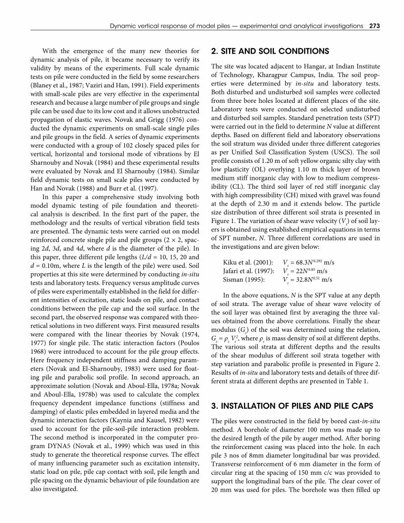
The site was located adjacent to Hangar, at Indian Institute of Technology, Kharagpur Campus, India. The soil prop-erties were determined by in-situ and laboratory tests. Both disturbed and undisturbed soil samples were collected from three bore holes located at different places of the site. Laboratory tests were conducted on selected undisturbed and disturbed soil samples. Standard penetration tests (SPT) were carried out in the field to determine N value at different depths. Based on different field and laboratory observations the soil stratum was divided under three different categories as per Unified Soil Classification System (USCS). The soil profile consists of 1.20 m of soft yellow organic silty clay with low plasticity (OL) overlying 1.10 m thick layer of brown medium stiff inorganic clay with low to medium compress-ibility (CL). The third soil layer of red stiff inorganic clay with high compressibility (CH) mixed with gravel was found at the depth of 2.30 m and it extends below. The particle sizedistributionofthreedifferentsoilstrataispresentedinFigure 1. The variation of shear wave velocity (Vs) of soil lay-ers is obtained using established empirical equations in terms of SPT number, N. Three different correlations are used in the investigations and are given below:
Kiku et al. (2001): Vs = 68.3N 0.292 m/sJafari et al. (1997): Vs = 22N 0.85 m/sSisman (1995): Vs = 32.8N0.51 m/s
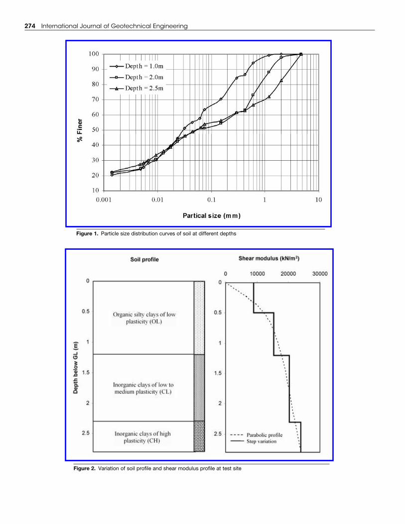
In the above equations, N is the SPT value at any depth of soil strata. The average value of shear wave velocity of the soil layer was obtained first by averaging the three val-ues obtained from the above correlations. Finally the shear modulus (Gs) of the soil was determined using the relation, Gs = ρs Vs
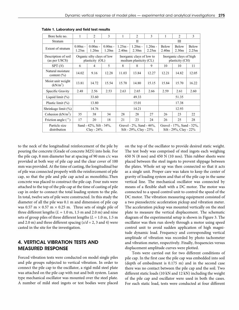
2, where ρs is mass density of soil at different depths. The various soil strata at different depths and the results of the shear modulus of different soil strata together with step variation and parabolic profile is presented in Figure 2. Results of in-situ and laboratory tests and details of three dif-ferent strata at different depths are presented in Table 1.
3. INSTALLATION OF PILES AND PILE CAPS
The piles were constructed in the field by bored cast-in-situ method. A borehole of diameter 100 mm was made up to the desired length of the pile by auger method. After boring the reinforcement casing was placed into the hole. In each pile 3 nos of 8mm diameter longitudinal bar was provided. Transverse reinforcement of 6 mm diameter in the form of circular ring at the spacing of 150 mm c/c was provided to support the longitudinal bars of the pile. The clear cover of 20 mm was used for piles. The borehole was then filled up
274 International Journal of Geotechnical Engineering
Figure 1. Particle size distribution curves of soil at different depths
Figure 2. Variation of soil profile and shear modulus profile at test site
Dynamic vertical response of model piles — experimental and analytical investigations 275
to the neck of the longitudinal reinforcement of the pile by pouring the concrete (Grade of concrete M25) into hole. For the pile cap, 8 mm diameter bar at spacing of 90 mm c/c was provided at both way of pile cap and the clear cover of 100 mm was provided. At the time of casting, the longitudinal bar of pile was connected properly with the reinforcement of pile cap, so that the pile and pile cap acted as monolithic.Then concrete was placed to construct the pile cap. Four nuts were attached to the top of the pile cap at the time of casting of pile cap in order to connect the total loading system to the pile. In total, twelve sets of pile were constructed. In this study the diameter of all the pile was 0.1 m and dimension of pile cap was 0.57 m × 0.57 m × 0.25 m. Three sets of single pile of three different lengths (L = 1.0 m, 1.5 m and 2.0 m) and nine sets of group piles of three different lengths (L = 1.0 m, 1.5 m and 2.0 m) and three different spacing (s/d = 2, 3 and 4) were casted in the site for the investigation.
4. VERTICAL VIBRATION TESTS AND MEASURED RESPONSE
Forced vibration tests were conducted on model single piles and pile groups subjected to vertical vibration. In order to connect the pile cap to the oscillator, a rigid mild steel plate wasattachedonthepilecapwithnutandboltsystem.Lazantype mechanical oscillator was mounted over the steel plate. A number of mild steel ingots or test bodies were placed
on the top of the oscillator to provide desired static weight. The test body was comprised of steel ingots each weighing 650 N (8 nos) and 450 N (10 nos). Thin rubber sheets were placed between the steel ingots to prevent slippage between the plates. Whole set up was then connected so that it acts as a single unit. Proper care was taken to keep the center of gravity of loading system and that of the pile cap in the same vertical line. The mechanical oscillator was connected by means of a flexible shaft with a DC motor. The motor was connected to a speed control unit to control the speed of the DC motor. The vibration measuring equipment consisted of atwopiezoelectricaccelerationpickupandvibrationmeter.The acceleration pickup was mounted vertically on the steel plate to measure the vertical displacement. The schematic diagram of the experimental setup is shown in Figure 3. The oscillator was then run slowly through a motor using speed control unit to avoid sudden application of high magni-tude dynamic load. Frequency and corresponding vertical amplitude of vibration was recorded by photo tachometer and vibration meter, respectively. Finally, frequencies versus displacement amplitude curves were plotted.
Tests were carried out for two different conditions of pile cap. In the first case the pile cap was embedded into soil (depth of embedment is 0.175 m) and in the second case there was no contact between the pile cap and the soil. Two different static loads (10 kN and 12 kN) including the weight of the pile cap and oscillator were used in both the cases. For each static load, tests were conducted at four different
Table 1. Laboratory and field test results
Table 1. Laboratory and field test results
Bore hole no. 1 2 3 1 2 3 1 2 3 Stratum I II III
Extent of stratum 0.00m - 1.25m
0.00m - 1.20m
0.00m - 1.20m
1.25m - 2.40m
1.20m - 2.30m
1.20m - 2.25m
Below 2.40m
Below 2.30m
Below 2.25m
Description of soil (as per USCS)
Organic silty clays of low plasticity (OL)
Inorganic clays of low to medium plasticity (CL)
Inorganic clays of high plasticity (CH)
SPT (N) 6 4 5 8 8 9 10 10 11 Natural moisture
content (%) 14.02 9.16 12.28 11.03 13.84 12.27 12.21 14.82 12.05
Moist unit weight (kN/m3) 13.81 14.72 15.54 15.70 14.80 15.15 15.84 15.70 16.22
Specific Gravity 2.48 2.56 2.53 2.63 2.65 2.66 2.59 2.61 2.60
Liquid limit (%) 33.60 49.33 51.35
Plastic limit (%) 13.80 15.01 17.38
Shrinkage limit (%) 14.76 14.21 12.93 Cohesion (kN/m2) 35 38 34 28 28 27 26 23 22 Friction angle ( o ) 17 20 18 21 23 24 26 25 28
Particle size distribution
Sand - 42%, Silt - 34%, Clay - 24%
Gravel - 2%, Sand - 46%, Silt - 29%, Clay - 23%
Gravel - 17%, Sand - 32%, Silt - 29%, Clay - 22%
276 International Journal of Geotechnical Engineering
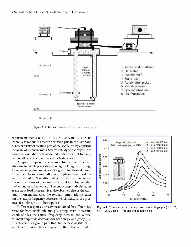
eccentric moments W.e (0.187, 0.278, 0.366, and 0.450 N-m, where W is weight of eccentric rotating part in oscillator and e is eccentricity of rotating part of the oscillator) by adjusting the angle of eccentric mass. Steady state dynamic response to harmonic excitation was measured under different frequen-cies for all eccentric moments at each static load.
A typical frequency versus amplitude curve of vertical vibration for single pile is shown in Figure 4. Figure 5 through 7 present response curves for pile group for three different L/d ratios. The response indicates a single resonant peak for vertical vibration. The effects of static loads on the vertical dynamic response of piles are studied and it is observed that the both natural frequency and resonant amplitude decreases as the static load increases. It is also observed that as the exci-tation moment increases the resonant amplitude increases but the natural frequency decreases which indicates the pres-ence of nonlinearity in the response.
Different response curves were obtained for different L/d ratios for both single pile and pile group. With increasing length of piles, the natural frequency increases and vertical resonant amplitude decreases for both single and group pile. It is observed for group piles that the increase of stiffness is very less for L/d of 20 as compared to the stiffness of L/d of
Figure 3. Schematic diagram of the experimental set-up
Figure 4. Experimental vertical response curve of single pile (L/d = 20, Ws = 10kN, Case I — Pile cap embedded in soil)
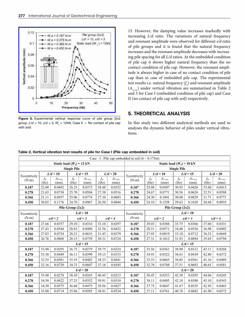
15. However, the damping value increases markedly with increasing L/d ratio. The variations of natural frequency and resonant amplitude were observed for different s/d ratio of pile groups and it is found that the natural frequency increases and the resonant amplitude decreases with increas-ing pile spacing for all L/d ratios. At the embedded condition of pile cap it shows higher natural frequency than the no contact condition of pile cap. However, the resonant ampli-tude is always higher in case of no contact condition of pile cap than in case of embedded pile cap. The experimental test results i.e. natural frequency (fn) and resonant amplitude (AV-res) under vertical vibration are summarized in Table 2and 3 for Case I (embedded condition of pile cap) and Case II (no contact of pile cap with soil) respectively.
5. THEORETICAL ANALySIS
In this study two different analytical methods are used to analyses the dynamic behavior of piles under vertical vibra-tions.
277 International Journal of Geotechnical Engineering
Figure 5. Experimental vertical response curve of pile group (2x2 group, L/d = 10, s/d = 3, Ws = 12kN, Case II — No contact of pile cap with soil)
Table 2. Vertical vibration test results of pile for Case I (Pile cap embedded in soil)
Table 2. Vertical vibration test results of pile for Case I (Pile cap embedded in soil)
Case - I : Pile cap embedded in soil (h = 0.175m)
Static load (Ws) = 12 kN Static load (Ws) = 10 kN Single Pile Single Pile
Eccentricity (N-m)
L/d = 10 L/d = 15 L/d = 20 Eccentricity (N-m)
L/d = 10 L/d = 15 L/d = 20 f
(Hz) m AV-res
(mm) f
(Hz) m AV-res
(mm) f
(Hz) m AV-res
(mm) f
(Hz) m AV-res
(mm) f
(Hz) m AV-res
(mm) f
(Hz) m AV-res
(mm) 0.187 22.00 0.0492 26.23 0.0373 28.48 0.0352 0.187 25.08 0.0507 30.93 0.0426 33.60 0.0413 0.278 21.63 0.0738 25.70 0.0584 27.38 0.0516 0.278 24.67 0.0771 30.56 0.0626 32.51 0.0588 0.366 21.11 0.0957 25.06 0.0774 27.10 0.0683 0.366 24.30 0.1041 30.08 0.0829 31.71 0.0771 0.450 20.65 0.1176 24.70 0.0967 26.50 0.0844 0.450 24.10 0.1258 29.63 0.1038 30.68 0.0935
Pile Group (2x2) Pile Group (2x2)
Eccentricity (N-m)
L/d = 10 Eccentricity (N-m)
L/d = 10 s/d = 2 s/d = 3 s/d = 4 s/d = 2 s/d = 3 s/d = 4
0.187 27.66 0.0357 29.10 0.0316 33.10 0.0297 0.187 29.03 0.0388 35.75 0.0366 37.60 0.0331 0.278 27.43 0.0544 28.83 0.0490 32.56 0.0432 0.278 28.51 0.0571 34.48 0.0536 36.98 0.0492 0.366 27.03 0.0724 28.21 0.0655 31.43 0.0579 0.366 27.93 0.0819 33.10 0.0712 36.33 0.0669 0.450 26.76 0.0868 28.15 0.0759 30.31 0.0724 0.450 27.31 0.1012 31.93 0.0894 35.65 0.0794
L/d = 15 L/d = 15 0.187 33.90 0.0295 36.75 0.0279 39.75 0.0224 0.187 35.56 0.0361 38.98 0.0312 43.11 0.0266 0.278 33.38 0.0449 36.11 0.0390 39.15 0.0333 0.278 34.93 0.0522 38.61 0.0430 42.80 0.0372 0.366 32.55 0.0581 35.35 0.0482 38.33 0.0441 0.366 33.33 0.0665 38.05 0.0561 41.16 0.0489 0.450 32.16 0.0729 34.73 0.0607 37.18 0.0545 0.450 32.78 0.0788 37.51 0.0692 40.65 0.0581
L/d = 20 L/d = 20 0.187 35.48 0.0278 38.10 0.0265 40.45 0.0213 0.187 38.45 0.0333 42.58 0.0295 44.06 0.0245 0.278 34.58 0.0422 37.25 0.0352 39.91 0.0310 0.278 38.11 0.0485 42.18 0.0380 43.10 0.0343 0.366 34.30 0.0575 36.60 0.0475 39.56 0.0427 0.366 37.75 0.0647 41.67 0.0535 42.45 0.0465 0.450 33.80 0.0714 35.86 0.0585 38.81 0.0534 0.450 37.11 0.0761 40.78 0.0682 41.90 0.0572
278 International Journal of Geotechnical Engineering
5.1. Novak’s Frequency Independent Solutions
With the harmonic motion, w(z,t) = w(z)eiωt, the complete solution for the pile amplitude w(z) and the pile impedances can be obtained. From these, Novak (1974, 1977) proposed the expression for the stiffness (k1
w) and damping constant (c1
w) of single pile for the vertical vibration as:
11
pw w
o
E Ak f
r
(1)
12
pw w
s
E Ac f
V
(2)
in which w(z) is complex amplitude at depth z, i = –1 , ω is circular frequency, t is time, Vs is the shear wave velocity in the lowest layer of soil at the pile tip; Ep is the Young’s modulus of the pile material; A is the pile’s cross sectional area; fw1 and fw2 are the dimensionless stiffness and damping parameters of soil-pile system.
Since the stiffness and damping parameter of pile do not depend much on frequency, Novak (1977) has recom-mended two parameters namely, fw1 and fw2 for design pur-poses which are independent of frequency. The stiffness and damping constants of pile for different mode of vibra-tions were introduced in the form of tables and charts by Novak and El-Sharnouby (1983) for homogeneous soil and parabolic soil profile for both floating and end bearing pile. Most important factors controlling the stiffness and damp-ing functions for vertical vibration were the stiffness ratio relating soil stiffness to pile stiffness, the soil profile, the tip condition of pile and the ratio of length to diameter of pile. These stiffness and damping parameters were calculated with material damping tanδl = 0.005 for soil and 0.01 for piles, dimensionless mass ratio, bo = 1, and constant dimensionless frequency, ao = 0.3. In this study the stiffness and damp-ing parameters of vertical vibration were obtained from the charts given by Novak and El-Sharnouby (1983) for floating pile and parabolic soil profile.
For group of piles supporting a pile cap, the total stiffness and damping constants were obtained as a sum of contribu-tions from the individual piles. The displacement of one pile
Table 3. Vertical vibration test results of pile for Case II (No contact of pile cap with soil)
Table 3. Vertical vibration test results of pile for Case II (No contact of pile cap with soil)
Case - II : No contact of pile cap with soil (h = 0)
Static load (Ws) = 12 kN Static load (Ws) = 10 kN Single Pile Single Pile
Eccentricity (N-m)
L/d = 10 L/d = 15 L/d = 20 Eccentricity (N-m)
L/d = 10 L/d = 15 L/d = 20 f
(Hz) m AV-res
(mm) f
(Hz) m AV-res
(mm) f
(Hz) m AV-res
(mm) f
(Hz) m AV-res
(mm) f
(Hz) m AV-res
(mm) f
(Hz) m AV-res
(mm) 0.187 21.11 0.0743 25.91 0.0612 26.18 0.0540 0.187 23.87 0.0832 27.15 0.0694 29.86 0.0583 0.278 20.53 0.1002 25.43 0.0851 25.93 0.0737 0.278 23.11 0.1132 26.88 0.0987 28.85 0.0852 0.366 19.10 0.1285 24.88 0.1121 25.23 0.0947 0.366 22.53 0.1433 26.33 0.1291 28.03 0.1148 0.450 18.76 0.1483 24.23 0.1373 24.82 0.1205 0.450 21.83 0.1762 25.63 0.1589 27.60 0.1456
Pile Group (2x2) Pile Group (2x2)
Eccentricity (N-m)
L/d = 10 Eccentricity (N-m)
L/d = 10 s/d = 2 s/d = 3 s/d = 4 s/d = 2 s/d = 3 s/d = 4
0.187 24.30 0.0457 27.90 0.0363 31.50 0.0340 0.187 27.85 0.0513 32.53 0.0475 35.45 0.0572 0.278 23.75 0.0684 27.33 0.0561 29.66 0.0522 0.278 27.41 0.0766 31.75 0.0697 34.47 0.0620 0.366 23.21 0.0934 26.81 0.0762 28.75 0.0732 0.366 26.85 0.1002 31.31 0.0995 33.34 0.0784 0.450 22.51 0.1128 26.21 0.0937 27.98 0.0888 0.450 26.46 0.1261 30.55 0.1008 32.21 0.0936
L/d = 15 L/d = 15 0.187 29.61 0.0358 35.45 0.0317 38.21 0.0262 0.187 34.51 0.0394 37.95 0.0344 42.50 0.0318 0.278 29.22 0.0510 34.41 0.0422 36.71 0.0381 0.278 33.21 0.0586 37.11 0.0489 41.53 0.0427 0.366 28.95 0.0633 33.35 0.0589 35.18 0.0501 0.366 32.38 0.0749 36.86 0.0637 40.11 0.0551 0.450 28.46 0.0832 32.73 0.0707 33.50 0.0619 0.450 31.01 0.0915 36.13 0.0755 38.45 0.0683
L/d = 20 L/d = 20 0.187 32.48 0.0345 36.18 0.0295 38.06 0.0265 0.187 35.41 0.0365 39.68 0.0335 43.31 0.0305 0.278 31.88 0.0475 35.43 0.0429 37.03 0.0375 0.278 34.95 0.0586 38.25 0.0465 42.21 0.0432 0.366 30.68 0.0601 34.85 0.0588 36.31 0.0485 0.366 34.21 0.0765 37.86 0.0602 41.76 0.0542 0.450 29.46 0.0745 33.66 0.0711 35.61 0.0589 0.450 33.73 0.0885 36.43 0.0725 40.68 0.0676
Dynamic vertical response of model piles — experimental and analytical investigations 279
was increased due to the displacements of all the other pile when the piles were closely spaced. Novak and Grigg (1976) proposed that the static interaction factors of Poulos (1968) for group action of statically loaded piles based on elastic analysis could also be applied to a pile group undergoing steady state vibration. Therefore, the pile group stiffness (kg
w) and damping (cg
w) can be written as:
1
1
g ww n
rr
nkk
(3)
1
1
g ww n
rr
ncc
(4)
where, n = number of piles in a group, αr = the static interac-tion factor describing the contribution of the r th pile to the displacement of the reference pile; α1 = 1; and all the other factors are smaller than unity and decreasing with distance between the piles.
When the pile cap is embedded into the soil, the stiffness and damping of pile is increased due to the soil reactions acting on the vertical sides of the pile cap. The soil reactions acting on the base area are not considered as the contact between the base of the cap and the soil is lost due to the soil settlement. The stiffness (kf
w) and damping (c fw) values due to
side friction of the pile cap (Novak and Beredugo, 1972) is given below:
kfw = Gsh
–S1 (5)
c hr S Gwf
s s= 0 2 ρ (6)
where h is depth of the embedded cap and r0 is equivalent radius of the cap. Gs and ρs are the shear modulus and total mass density of the backfill and –S1 and –S2 are stiffness and damping parameter of side layers for vertical vibration respectively.
From the principle of vibration the damped natural fre-quency and resonant amplitude of pile in vertical vibrations can be expressed as:
21 2
nm
ffD
(7)
22 1
res
s
meAm D D
(8)
where natural frequency, f k
mnwg
s
=12π
, damping ratio,
D ck m
wg
w s
=2 1 , ms(=Ws/g) is mass of external static load includ-
ing machine, m(=W/g) is mass of the eccentric rotating part and e is eccentricity of rotating part.
5.2. Novak’s Frequency Dependent Solutions - Dyna5 Approach
DYNA5 (Novak et al., 1999) used the dynamic impedance function approach (Novak and Aboul-Ella 1978a, b) in which the stiffness and damping parameters of single piles were determined from complex and frequency dependent imped-ance functions derived from analytical solutions of the foun-dation vibration problems. In this approach, the dynamic soil reactions to the displacements of a pile element were calcu-lated assuming that the soil consist of infinitely thin layers extendinghorizontallytoinfinity.Foraharmonicexcitationat a particular frequency, the dynamic impedance is defined as the ratio between the steady-state force (or moment) and the resulting displacement (or rotation) at the base of a rigid massless foundation. The dynamic impedance function can be expressed in complex notation as:
K = K1 + iK2 = k + iωc (9)
in which K1 and K2 are the real part and imaginary part of the complex stiffness K, k = K1 is the dynamic stiffness and c = K2/ω is the constant of equivalent viscous damping, ω = circular frequency of excitation and i = –1 . The constant, c, accounts for energy dissipation in soil stemming from wave propagation (geometric damping) and from soil hysteresis (material damping). The stiffness and damping values, k and c, vary with frequency.
The pile group interaction analysis incorporated in DYNA5 is based on the practical concept of “interaction factors” proposed by Poulos (1968, 1971) for static loading and later extended by Kaynia and Kausel (1982) to dynamic loading. The interaction factor approach assumes that the pile group effect can be assessed by simply superimposing the interaction effects of two piles at a time. As the dynamic inter-action factors are currently available for very limited floating pile group situations, a hybrid approach is used in DYNA5 in which the frequency variation of the dynamic interaction factors in Kaynia and Kausel (1982) are used to modify the more complete static interaction factors available in Poulos and Davis (1980) for vertical loading and El-Sharnouby and Novak (1986) forhorizontal loading.This approach allowsimportant factors such as frequency variation, pile spacing, pile length to diameter ratio, relative pile-soil rigidity, and pile tip condition to be considered in the interaction factors. The pile group impedances are calculated from the single pile impedances and the dynamic interaction factors in a rigor-ous manner, using closed-form formulae derived by Novak and Mitwally (1990).

280 International Journal of Geotechnical Engineering
In this study, the dynamic interaction factor method is used to perform the relevant theoretical analyses. For two identical and equally loaded piles i and j, the interaction fac-tor αij is defined as:
dijij
sjj
(10)
where δdij is dynamic displacement of pile i due to load on pile j, and δsjj is static displacement of pile j due to its own load. Both static and dynamic displacements are referred to the pile head.
The dynamic interaction factors to be used in the analy-sis are complex and it is given as follows:
α = α1 + iα2 (11)
in which α1 and α2 are the real and imaginary parts respec-tively; i = –1 .
The value of dynamic interaction factors depends on dimensionless frequency, ao(= ωr/Vs), pile spacing ratio, s/d, pile slenderness ratio, L/d, and the modulus ratio, Ep/Es. If the pile slenderness ratio, L/d, and the modulus ratio, Ep/Es, are assumed to have relatively little effect on the frequency variation, at least in the low frequency range, the dynamic interaction factors can be expressed as:
α(ao, s/d, L/d, Ep/Es) = αst(ao= 0, s/d, L/d, Ep/Es) F(ao, s/d) (12)
in which αst is static interaction factor and F(ao, s/d) rep-resents the frequency variation which is derived using the interpolation scheme from the dynamic interaction factors developed by Kaynia and Kausel (1982).
From Eqn. (10), the compatibility equations can be expressed in terms of flexibility as:
{δ} = fst [α] {P} = [f] {P} (13)
in which fst is the static flexibility of a single pile, {P} and {δ} are the vectors of forces and displacements at the pile head respectively; [f] is the group flexibility matrix; [α] is the [n × n] matrix of interaction factors, where n is the number of piles.Forverticaltranslationorpurehorizontaltranslation,the Eqn. (13) is directly applicable. Inversion of the flexibility matrix results in the group stiffness matrix.
The complex foundation stiffness in different modes of vibration is calculated by applying the pertinent boundary conditions for rigid foundations. The boundary condition for vertical stiffness calculation is: vertical displacement, Vi = 1, for i = 1, 2 . . . n. The vertical stiffness of pile group is then calculated by:
1 1
n nV
V V iji j
K K
(14)
where K–V is the vertical stiffness of single pile, εVij are the
elements of [α]–1V; [α]V is the interaction matrix of vertical
displacements. To account for the embedment effect of pile cap, Novak
and Beredugo (1972) introduced some expressions for stiff-ness and damping of embedded footing under vertical vibrations using plane strain soil model. In this analysis the soil reactions acting the base area of cap are normally not included and only the soil reaction acting on the vertical sides of pile cap are considered. The side reactions due to
Figure 7. Experimental vertical response curve of pile group (2 x 2 group, L/d = 20, s/d = 3, Ws = 12kN, Case II — No contact of pile cap with soil)
Figure 6. Experimental vertical response curve of pile group (2 x 2 group, L/d = 15, s/d = 3, Ws = 12kN, Case II — No contact of pile cap with soil)
Dynamic vertical response of model piles — experimental and analytical investigations 281
pile cap embedment results in increased pile stiffness and damping.
The theoretical calculations of single piles and pile groups under vertical vibration were performed using the computer program DYNA5, which employs the previous assumptions and procedure. Theoretical response curves of piles obtained from DYNA5 are compared with the experi-mental results.
6. THEORy VERSUS EXPERIMENT
6.1. Frequency Independent Solutions — Using Static Interaction Factor
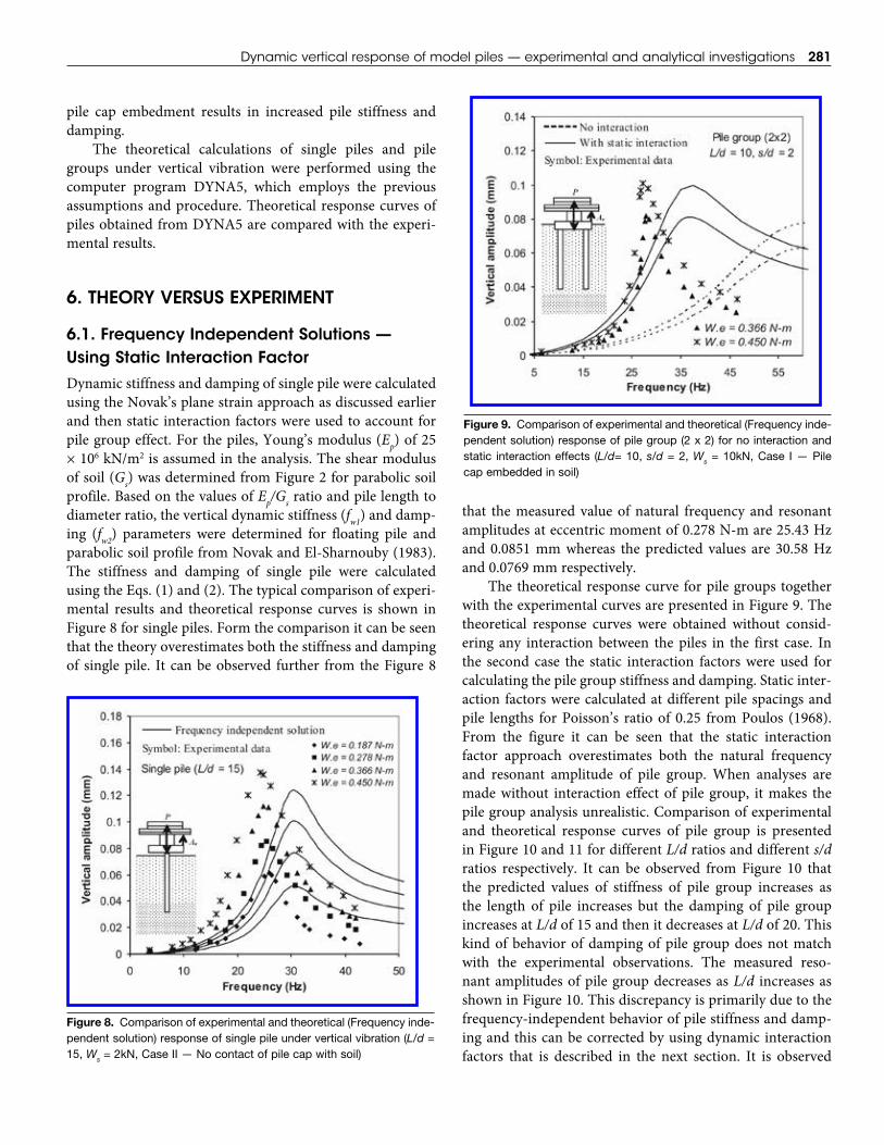
Dynamic stiffness and damping of single pile were calculated using the Novak’s plane strain approach as discussed earlier and then static interaction factors were used to account for pile group effect. For the piles, Young’s modulus (Ep) of 25 × 106 kN/m2 is assumed in the analysis. The shear modulus of soil (Gs) was determined from Figure 2 for parabolic soil profile. Based on the values of Ep/Gs ratio and pile length to diameter ratio, the vertical dynamic stiffness (fw1) and damp-ing (fw2) parameters were determined for floating pile and parabolic soil profile from Novak and El-Sharnouby (1983). The stiffness and damping of single pile were calculated using the Eqs. (1) and (2). The typical comparison of experi-mental results and theoretical response curves is shown in Figure 8 for single piles. Form the comparison it can be seen that the theory overestimates both the stiffness and damping of single pile. It can be observed further from the Figure 8
that the measured value of natural frequency and resonant amplitudesateccentricmomentof0.278N-mare25.43Hzand 0.0851mmwhereas the predicted values are 30.58Hzand 0.0769 mm respectively.
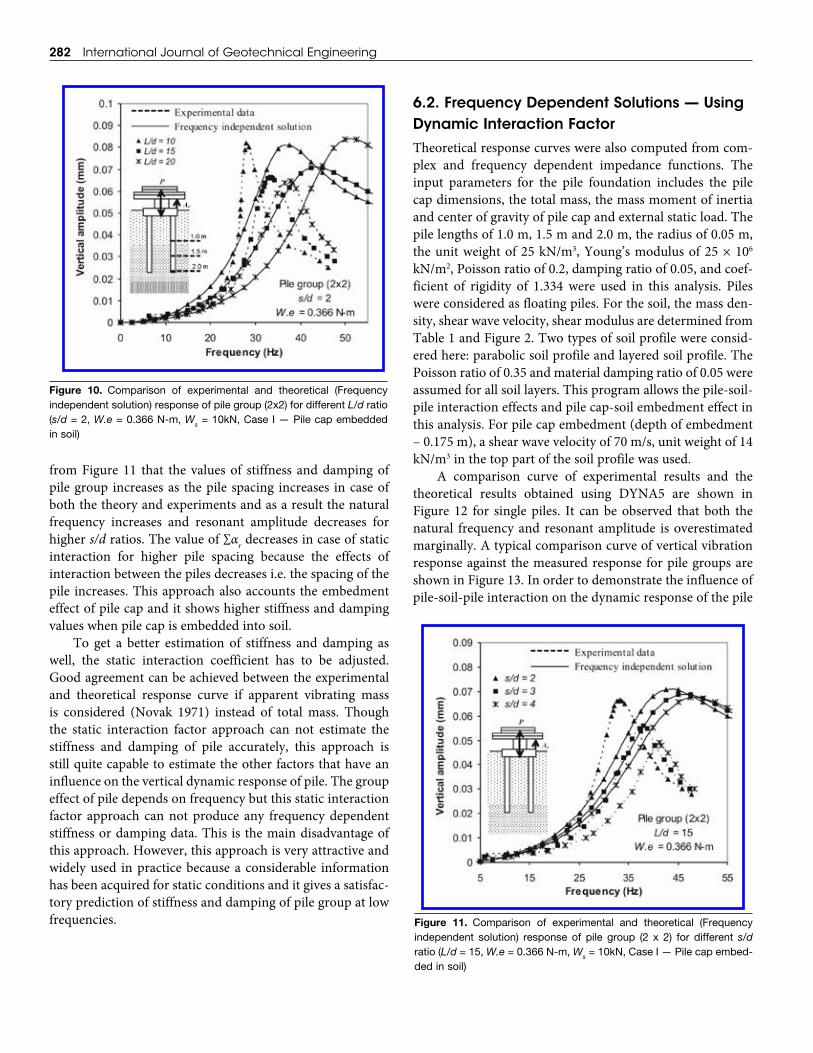
The theoretical response curve for pile groups together with the experimental curves are presented in Figure 9. The theoretical response curves were obtained without consid-ering any interaction between the piles in the first case. In the second case the static interaction factors were used for calculating the pile group stiffness and damping. Static inter-action factors were calculated at different pile spacings and pile lengths for Poisson’s ratio of 0.25 from Poulos (1968). From the figure it can be seen that the static interaction factor approach overestimates both the natural frequency and resonant amplitude of pile group. When analyses are made without interaction effect of pile group, it makes the pile group analysis unrealistic. Comparison of experimental and theoretical response curves of pile group is presented in Figure 10 and 11 for different L/d ratios and different s/d ratios respectively. It can be observed from Figure 10 that the predicted values of stiffness of pile group increases as the length of pile increases but the damping of pile group increases at L/d of 15 and then it decreases at L/d of 20. This kind of behavior of damping of pile group does not match with the experimental observations. The measured reso-nant amplitudes of pile group decreases as L/d increases as shown in Figure 10. This discrepancy is primarily due to the frequency-independent behavior of pile stiffness and damp-ing and this can be corrected by using dynamic interaction factors that is described in the next section. It is observed
Figure 8. Comparison of experimental and theoretical (Frequency inde-pendent solution) response of single pile under vertical vibration (L/d = 15, Ws = 2kN, Case II — No contact of pile cap with soil)
Figure 9. Comparison of experimental and theoretical (Frequency inde-pendent solution) response of pile group (2 x 2) for no interaction and static interaction effects (L/d= 10, s/d = 2, Ws = 10kN, Case I — Pile cap embedded in soil)
282 International Journal of Geotechnical Engineering
from Figure 11 that the values of stiffness and damping of pile group increases as the pile spacing increases in case of both the theory and experiments and as a result the natural frequency increases and resonant amplitude decreases for higher s/d ratios. The value of ∑αr decreases in case of static interaction for higher pile spacing because the effects of interaction between the piles decreases i.e. the spacing of the pile increases. This approach also accounts the embedment effect of pile cap and it shows higher stiffness and damping values when pile cap is embedded into soil.
To get a better estimation of stiffness and damping as well, the static interaction coefficient has to be adjusted. Good agreement can be achieved between the experimental and theoretical response curve if apparent vibrating mass is considered (Novak 1971) instead of total mass. Though the static interaction factor approach can not estimate the stiffness and damping of pile accurately, this approach is still quite capable to estimate the other factors that have an influence on the vertical dynamic response of pile. The group effect of pile depends on frequency but this static interaction factor approach can not produce any frequency dependent stiffness or damping data. This is the main disadvantage of this approach. However, this approach is very attractive and widely used in practice because a considerable information has been acquired for static conditions and it gives a satisfac-tory prediction of stiffness and damping of pile group at low frequencies.
6.2. Frequency Dependent Solutions — Using Dynamic Interaction Factor
Theoretical response curves were also computed from com-plex and frequency dependent impedance functions. The input parameters for the pile foundation includes the pile cap dimensions, the total mass, the mass moment of inertia and center of gravity of pile cap and external static load. The pile lengths of 1.0 m, 1.5 m and 2.0 m, the radius of 0.05 m, the unit weight of 25 kN/m3, Young’s modulus of 25 × 106 kN/m2, Poisson ratio of 0.2, damping ratio of 0.05, and coef-ficient of rigidity of 1.334 were used in this analysis. Piles were considered as floating piles. For the soil, the mass den-sity, shear wave velocity, shear modulus are determined from Table 1 and Figure 2. Two types of soil profile were consid-ered here: parabolic soil profile and layered soil profile. The Poisson ratio of 0.35 and material damping ratio of 0.05 were assumed for all soil layers. This program allows the pile-soil-pile interaction effects and pile cap-soil embedment effect in this analysis. For pile cap embedment (depth of embedment – 0.175 m), a shear wave velocity of 70 m/s, unit weight of 14 kN/m3 in the top part of the soil profile was used.
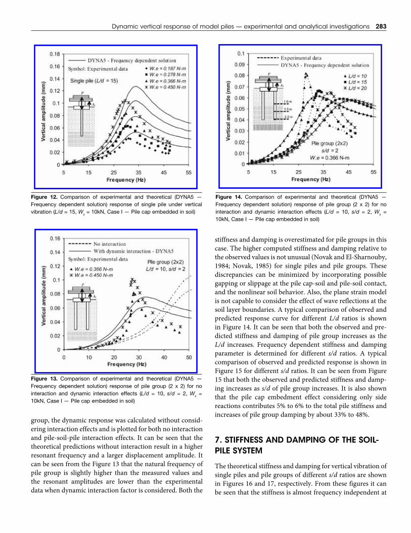
A comparison curve of experimental results and the theoretical results obtained using DYNA5 are shown in Figure 12 for single piles. It can be observed that both the natural frequency and resonant amplitude is overestimated marginally. A typical comparison curve of vertical vibration response against the measured response for pile groups are shown in Figure 13. In order to demonstrate the influence of pile-soil-pile interaction on the dynamic response of the pile
Figure 10. Comparison of experimental and theoretical (Frequency independent solution) response of pile group (2x2) for different L/d ratio (s/d = 2, W.e = 0.366 N-m, Ws = 10kN, Case I — Pile cap embedded in soil)
Figure 11. Comparison of experimental and theoretical (Frequency independent solution) response of pile group (2 x 2) for different s/d ratio (L/d = 15, W.e = 0.366 N-m, Ws = 10kN, Case I — Pile cap embed-ded in soil)
Dynamic vertical response of model piles — experimental and analytical investigations 283
group, the dynamic response was calculated without consid-ering interaction effects and is plotted for both no interaction and pile-soil-pile interaction effects. It can be seen that the theoretical predictions without interaction result in a higher resonant frequency and a larger displacement amplitude. It can be seen from the Figure 13 that the natural frequency of pile group is slightly higher than the measured values and the resonant amplitudes are lower than the experimental data when dynamic interaction factor is considered. Both the
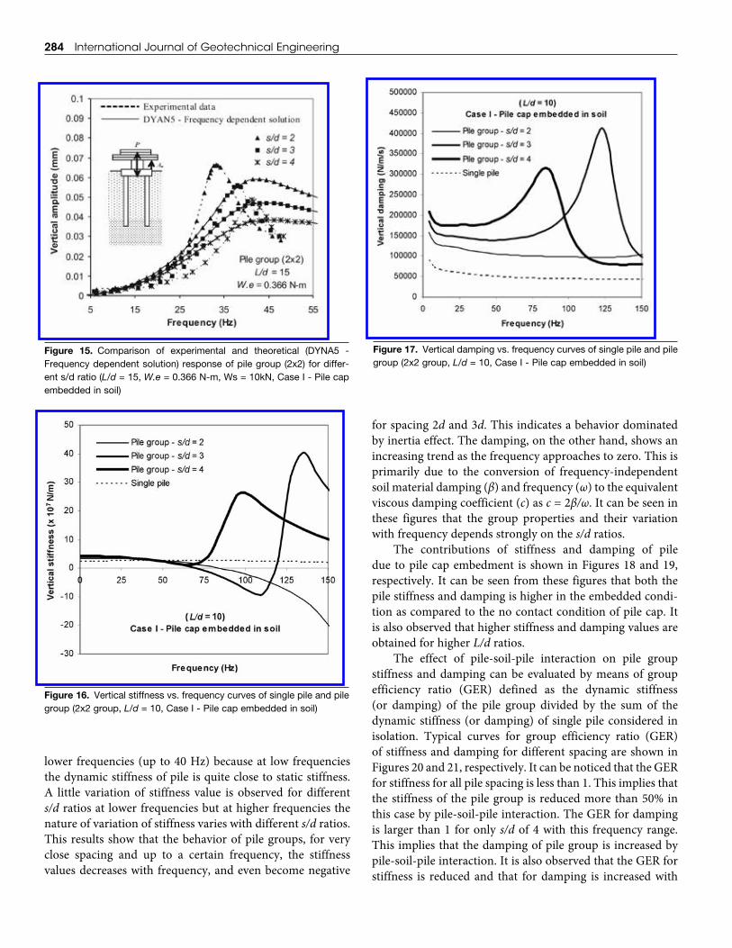
stiffness and damping is overestimated for pile groups in this case. The higher computed stiffness and damping relative to the observed values is not unusual (Novak and El-Sharnouby, 1984; Novak, 1985) for single piles and pile groups. These discrepancies can be minimized by incorporating possiblegapping or slippage at the pile cap-soil and pile-soil contact, and the nonlinear soil behavior. Also, the plane strain model is not capable to consider the effect of wave reflections at the soil layer boundaries. A typical comparison of observed and predicted response curve for different L/d ratios is shown in Figure 14. It can be seen that both the observed and pre-dicted stiffness and damping of pile group increases as the L/d increases. Frequency dependent stiffness and damping parameter is determined for different s/d ratios. A typical comparison of observed and predicted response is shown in Figure 15 for different s/d ratios. It can be seen from Figure 15 that both the observed and predicted stiffness and damp-ing increases as s/d of pile group increases. It is also shown that the pile cap embedment effect considering only side reactions contributes 5% to 6% to the total pile stiffness and increases of pile group damping by about 33% to 48%.
7. STIFFNESS AND DAMPINg OF THE SOIL-PILE SySTEM
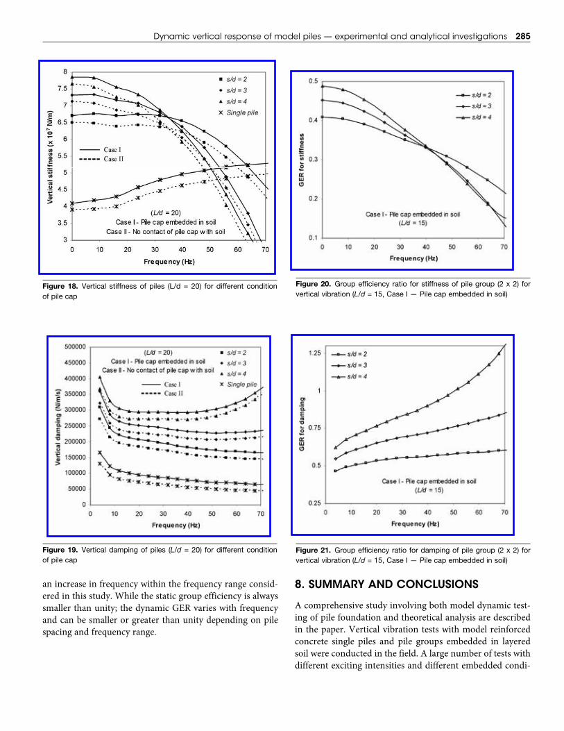
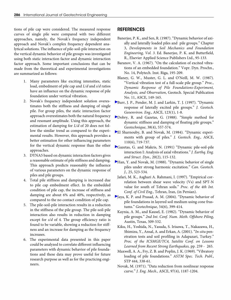
The theoretical stiffness and damping for vertical vibration of single piles and pile groups of different s/d ratios are shown in Figures 16 and 17, respectively. From these figures it can be seen that the stiffness is almost frequency independent at
Figure 12. Comparison of experimental and theoretical (DYNA5 — Frequency dependent solution) response of single pile under vertical vibration (L/d = 15, Ws = 10kN, Case I — Pile cap embedded in soil)
Figure 13. Comparison of experimental and theoretical (DYNA5 — Frequency dependent solution) response of pile group (2 x 2) for no interaction and dynamic interaction effects (L/d = 10, s/d = 2, Ws = 10kN, Case I — Pile cap embedded in soil)
Figure 14. Comparison of experimental and theoretical (DYNA5 — Frequency dependent solution) response of pile group (2 x 2) for no interaction and dynamic interaction effects (L/d = 10, s/d = 2, Ws = 10kN, Case I — Pile cap embedded in soil)
284 International Journal of Geotechnical Engineering
lower frequencies(upto40Hz)becauseat lowfrequenciesthe dynamic stiffness of pile is quite close to static stiffness. A little variation of stiffness value is observed for different s/d ratios at lower frequencies but at higher frequencies the nature of variation of stiffness varies with different s/d ratios. This results show that the behavior of pile groups, for very close spacing and up to a certain frequency, the stiffness values decreases with frequency, and even become negative
for spacing 2d and 3d. This indicates a behavior dominated by inertia effect. The damping, on the other hand, shows an increasingtrendasthefrequencyapproachestozero.Thisisprimarily due to the conversion of frequency-independent soil material damping (β) and frequency (ω) to the equivalent viscous damping coefficient (c) as c = 2β/ω. It can be seen in these figures that the group properties and their variation with frequency depends strongly on the s/d ratios.
The contributions of stiffness and damping of pile due to pile cap embedment is shown in Figures 18 and 19, respectively. It can be seen from these figures that both the pile stiffness and damping is higher in the embedded condi-tion as compared to the no contact condition of pile cap. It is also observed that higher stiffness and damping values are obtained for higher L/d ratios.
The effect of pile-soil-pile interaction on pile group stiffness and damping can be evaluated by means of group efficiency ratio (GER) defined as the dynamic stiffness (or damping) of the pile group divided by the sum of the dynamic stiffness (or damping) of single pile considered in isolation. Typical curves for group efficiency ratio (GER) of stiffness and damping for different spacing are shown in Figures 20 and 21, respectively. It can be noticed that the GER for stiffness for all pile spacing is less than 1. This implies that the stiffness of the pile group is reduced more than 50% in this case by pile-soil-pile interaction. The GER for damping is larger than 1 for only s/d of 4 with this frequency range. This implies that the damping of pile group is increased by pile-soil-pile interaction. It is also observed that the GER for stiffness is reduced and that for damping is increased with
Figure 15. Comparison of experimental and theoretical (DYNA5 - Frequency dependent solution) response of pile group (2x2) for differ-ent s/d ratio (L/d = 15, W.e = 0.366 N-m, Ws = 10kN, Case I - Pile cap embedded in soil)
Figure 16. Vertical stiffness vs. frequency curves of single pile and pile group (2x2 group, L/d = 10, Case I - Pile cap embedded in soil)
Figure 17. Vertical damping vs. frequency curves of single pile and pile group (2x2 group, L/d = 10, Case I - Pile cap embedded in soil)
Dynamic vertical response of model piles — experimental and analytical investigations 285
an increase in frequency within the frequency range consid-ered in this study. While the static group efficiency is always smaller than unity; the dynamic GER varies with frequency and can be smaller or greater than unity depending on pile spacing and frequency range.
8. SUMMARy AND CONCLUSIONS
A comprehensive study involving both model dynamic test-ing of pile foundation and theoretical analysis are described in the paper. Vertical vibration tests with model reinforced concrete single piles and pile groups embedded in layered soil were conducted in the field. A large number of tests with different exciting intensities and different embedded condi-
Figure 18. Vertical stiffness of piles (L/d = 20) for different condition of pile cap
Figure 19. Vertical damping of piles (L/d = 20) for different condition of pile cap
Figure 20. Group efficiency ratio for stiffness of pile group (2 x 2) for vertical vibration (L/d = 15, Case I — Pile cap embedded in soil)
Figure 21. Group efficiency ratio for damping of pile group (2 x 2) for vertical vibration (L/d = 15, Case I — Pile cap embedded in soil)
286 International Journal of Geotechnical Engineering
tions of pile cap were considered. The measured response curves of single pile were compared with two different approaches, namely, the Novak’s frequency independent approach and Novak’s complex frequency dependent ana-lytical solutions. The influence of pile-soil-pile interaction on the vertical dynamic behavior of pile groups was investigated using both static interaction factor and dynamic interaction factor approach. Some important conclusions that can be made from the theoretical and experimental investigations aresummarizedasfollows:
1. Many parameters like exciting intensities, static load, embedment of pile cap and L/d and s/d ratios have an influence on the dynamic response of pile foundation under vertical vibration.
2. Novak’s frequency independent solution overes-timates both the stiffness and damping of single pile. For group piles, the static interaction factor approach overestimates both the natural frequency and resonant amplitude. Using this approach, the estimation of damping for L/d of 20 does not fol-low the similar trend as compared to the experi-mental results. However, this approach provides a better estimation for other influencing parameters for the vertical dynamic response than the other approaches.
3. DYNA5 based on dynamic interaction factors gives a reasonable estimate of pile stiffness and damping. This approach predicts reasonably the influence of various parameters on the dynamic response of piles and pile groups.
4. Total pile stiffness and damping is increased due to pile cap embedment effect. In the embedded condition of pile cap, the increase of stiffness and damping are about 6% and 40%, respectively, as compared to the no contact condition of pile cap.
5. The pile-soil-pile interaction results in a reduction in the stiffness of the pile group. The pile-soil-pile interaction also results in reduction in damping except for s/d of 4. The group efficiency ratio is found to be variable, showing a reduction for stiff-ness and an increase for damping as the frequency increases.
6. The experimental data presented in this paper couldbeanalyzedtocorrelatedifferentinfluencingparameters with dynamic behavior of pile founda-tions and these data may prove useful for future research purpose as well as for the practicing engi-neers.
REFERENCES
Banerjee, P. K., and Sen, R. (1987). “Dynamic behavior of axi-ally and laterally loaded piles and pile groups.” Chapter 3, Developments in Soil Mechanics and Foundation Engineering, Vol. 3. Ed. Banerjee, P. K. and Butterfield, R., Elsevier Applied Science Publishers Ltd., 95-133.
Baranov, V. A. (1967). “On the calculation of excited vibra-tions of an embedded foundation.” Vopr. Dyn. Prochn., No. 14, Polytech. Inst. Riga, 195-209.
Blaney, G. W., Muster, G. L. and O’Neill, M. W. (1987). “Vertical vibration test of a full-scale pile group.” Proc., Dynamic Response of Pile Foundations-Experiment, Analysis, and Observation, Geotech. Special Publication No. 11, ASCE, 149-165.
Burr, J. P., Pender, M. J. and Larkin, T. J. (1997). “Dynamic response of laterally excited pile groups.” J. Geotech. Geoenviron. Eng., ASCE, 123(1), 1-8.
Dobry, R. and Gazetas, G. (1988). “Simple method fordynamic stiffness and damping of floating pile groups.” Geotechnique, 38(4), 557-574.
El Sharnouby, B. and Novak, M. (1984). “Dynamic experi-ments with group of piles.” J. Geotech. Eng., ASCE, 110(6), 719-737.
Gazetas, G. andMakris, N. (1991) “Dynamic pile-soil-pileinteraction I: Analysis of axial vibrations.” J. Earthq. Eng. and Struct. Dyn., 20(2), 115-132.
Han, Y. and Novak, M. (1988). “Dynamic behavior of single piles under strong harmonic excitation.” Can. Geotech. J., 25, 523-534.
Jafari, M. K., Asghari A. Rahmani, I. (1997). “Empirical cor-relation between shear wave velocity (Vs) and SPT-N value for south of Tehran soils.” Proc. of the 4th Int. Conf. of Civil Eng., Tehran, Iran, (in Persian).
Jaya, K. P. and Prasad, A. M. (2004). “Dynamic behavior of pile foundations in layered soil medium using cone frus-tums.” Geotechnique, 54(6), 399-414.
Kaynia, A. M., and Kausel, E. (1982). “Dynamic behavior of pile groups.” 2nd Int. Conf. Num. Meth. Offshore Piling, Austin, Texas, 509-532.
Kiku,H.,Yoshida,N.,Yasuda,S.Irisawa,T.,Nakazawa,H.,Shimizu,Y.,Ansal,A.andErkan,A.(2001).“In-situ pen-etration tests and soil profiling inAdapazari, Turkey.”Proc. of the ICSMGE/TC4, Satelite Conf. on Lessons Learned from Recent Strong Earthquakes, pp. 259 - 265.
Maxwell, A. A., Fry, Z. B. and Poplin, J. K. (1969). “Vibratory loading of pile foundations.” ASTM Spec. Tech. Publ., STP 444, 338-61.
Novak, M. (1971). “Data reduction from nonlinear response curve.” J. Eng. Mech., ASCE, 97(4), 1187-1204.
Dynamic vertical response of model piles — experimental and analytical investigations 287
Novak, M. (1974). “Dynamic stiffness and damping of piles.” Can. Geotech. J., 11, 574-598.
Novak, M. (1977). “Vertical vibration of floating piles.” J. Eng. Mech., ASCE, 103(1), 153-168.
Novak, M. (1985). “Experiments with shallow and deep foundations.” Vibration Problem in Geotech. Eng., ASCE Convention, Detroit, Mich., Oct., 1-26.
Novak, M., and Aboul-Ella, F. (1978a). “Impedance func-tions of piles in layered media.” J. Eng. Mech. Div., ASCE, 104(3), 643–661.
Novak, M., and Aboul-Ella, F. (1978b). “Stiffness and damp-ing of piles in layered media.” Proc. Earthq. Eng. and Soil Dyn., ASCE Specialty Conf., Pasadena, California, June 19 - 21, 704 - 719.
Novak, M and Beredugo, Y. O. (1972). “Vertical vibration of embedded footing.” J. Soil Mech. Found. Div., ASCE, 98(SM12), 1291-1310.
Novak, M., El-Naggar, M. H., Sheta, M., El-Hifnawy, L., El-Marsafawi, H., and Ramadan, O. (1999). “DYNA5 — a computer program for calculation of foundation response to dynamic loads.” Geotechnical Research Centre, Univ. of Western Ontario, London, Ontario.
Novak, M., and El Sharnouby, B. (1983). “Stiffness constants of single piles.” J. Geotech. Eng., ASCE, 109(7), 961-974.
Novak, M. and El Sharnouby, B. (1984). “Evaluation of dynamic experiments on pile groups.” J. Geotech. Eng., ASCE, 110(6), 738-756.
Novak, M., and Grigg, R. F. (1976). “Dynamic experiments with small pile foundations.” Can. Geotech. J., 13, 372-385.
Novak, M. and Mitwally, H. (1990). “Random response of offshore towers with pile-soil-pile interaction.” J. Offshore Mech. and Arctic Eng., 112, 35 - 41.
Novak, M and Nogami, T. (1977). “Soil pile interaction in horizontal vibration.” J. Earthq. Eng. and Struct. Dyn., 5(3), 263-282.
Novak, M., and Sheta, M. (1980). “Approximate approach to contact problems of piles.” Proc., “Dynamic Response of Pile Foundations: Analytical Aspects”, M. O’Neill et al., eds., ASCE, New York, 53–79.
Poulos, H. G. (1968). “Analysis of settlement of pile groups.” Geotechnique, 18, 449-471.
Poulos, H. G. (1971). “Behaviour of laterally loaded piles II - Pile groups.” J. Soil Mech. and Found. Div., ASCE, 97(5), 733-751.
Poulos, H. G. and Davis, E. H. (1980). Pile foundation analy-sis and design. John Wiley and Sons.
Richart, F. E., Hall, J. R. and Woods, R. D. (1970). Vibrations of soils and foundations. Prentice-Hall, Englewood Cliffs, New Jersey.
Sheta, M. and Novak, M. (1982). “Vertical Vibration of Pile Groups.” J. Geotech. Eng. Div., ASCE, 108(4), 570-590.
Sisman, H. (1995). “An investigation on relationships between shear wave velocity, and SPT and pressure meter test results.” M.Sc. Thesis, Ankara Univ., Geophysics Eng. Dept., Ankara.
Vaziri,H.andHan,Y.(1991).“Full-scalefieldstudiesofthedynamicresponseofpilesembeddedinpartiallyfrozensoils.” Can. Geotech. J., 28, 708-718.
Velez, A., Gazetas, G. and Krishnan, R. (1983). “Lateraldynamic response of constrained head piles.” J. Geotech. Eng., ASCE, 109(8), 1063-1081.
Wolf, J. P., Meek, J. W. and Song, C. (1992). “Cone models for a pile foundation.” Proc., Piles under dynamic loads, Geotech. Special Publication No. 34, ASCE, 94-113.


![ANALYTICAL INVESTIGATIONS ON PROPERTIES OF REACTANTS [H2 - AIR] AND PRODUCTS AT DIFFERENT EQUIVALENCE RATIO](https://img.pdfslide.us/doc/110x75/577cc5891a28aba7119cb87d/analytical-investigations-on-properties-of-reactants-h2-air-and-products.jpg)