Embed Size (px)
Citation preview
Dynamic User Interface Environment
Sun-Woo Kim
This project dissertation was submitted as fulfillment of a requirement forthe MSc in Data Engineering
Department of Computer Science,
Keele University,
Staffordshire ST5 5BG
September 1997

Acknowledgement
I would like to thank my parents, sister and brother for their love and support. I amdeeply thankful to Dr. Geoff Hamilton for supervising the project. My thank also goes toProfessor C.Y. Jin of Wonkwang University and Professor J.H. Lee of GSMIS for theirguidance and encouragement. Finally, I am grateful to M. Hamad for useful discussions.
ii
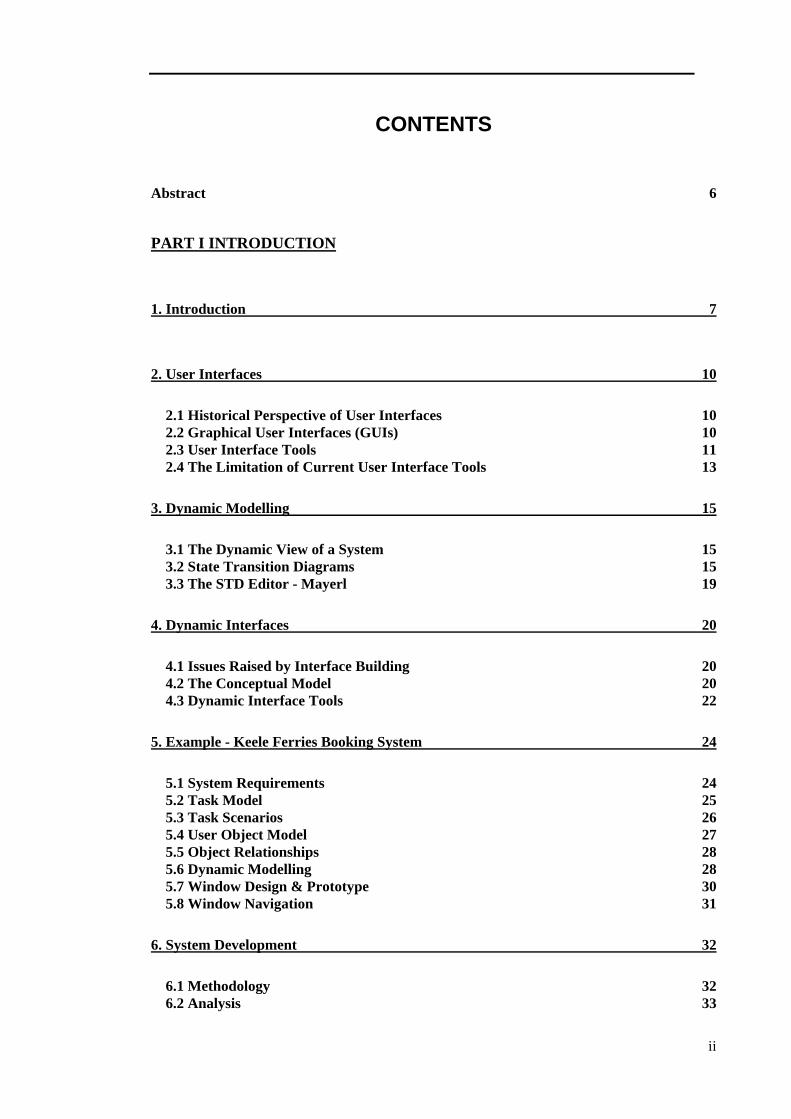
CONTENTS
Abstract 6
PART I INTRODUCTION
1. Introduction 7
2. User Interfaces 10
2.1 Historical Perspective of User Interfaces 102.2 Graphical User Interfaces (GUIs) 102.3 User Interface Tools 112.4 The Limitation of Current User Interface Tools 13
3. Dynamic Modelling 15
3.1 The Dynamic View of a System 153.2 State Transition Diagrams 153.3 The STD Editor - Mayerl 19
4. Dynamic Interfaces 20
4.1 Issues Raised by Interface Building 204.2 The Conceptual Model 204.3 Dynamic Interface Tools 22
5. Example - Keele Ferries Booking System 24
5.1 System Requirements 245.2 Task Model 255.3 Task Scenarios 265.4 User Object Model 275.5 Object Relationships 285.6 Dynamic Modelling 285.7 Window Design & Prototype 305.8 Window Navigation 31
6. System Development 32
6.1 Methodology 326.2 Analysis 33
iii
6.3 Design 346.4 Implementation 406.5 Testing 416.6 Developing the First Prototype to the Final Product 42
7. Interface Development 43
7.1 Methodology 437.2 User and Usability Specification 457.3 Task Analysis 467.4 Class Modelling 487.5 Initial GUI design - paper sketches 507.6 GUI prototyping 51
8. Result & Critical Evaluation 59
9. Conclusion 61
Bibliography 64
Appendices
Appendix A Statement of Purpose 65Appendix B Context Diagram 66Appendix C Data Flow Diagram 67Appendix D Entity-Relationship Diagram 68Appendix E Data Structures 70Appendix F Pseudo Code 72Appendix G Testing Form and Result 73Appendix H The Example Code of Interface Design 76Appendix I Source Code 80
iv
List of Figures
Figure 1 Example of state transition diagram - (Ward & Mellor, 1985, p68) 16
Figure 2 Example of statechart - (Harel, 1987, p246) 17
Figure 3 A state of State Diagram 18
Figure 4 The main screen of Mayerl STD editor 19
Figure 5 Linking of STDs and windows 21
Figure 6 Overview of the conceptual model 22
Figure 7 The task model of Keele ferries booking system 26
Figure 8 Object relationships 28
Figure 9 A STD of ‘Ferry Service’ object 29
Figure 10 A STD of ‘Customer’ object 29
Figure 11 A STD of ‘Holiday sites Service’ object 30
Figure 12 A STD of ‘Insurance’ object 30
Figure 13 'Holiday sites Booking' window 31
Figure 14 ‘Insurance’ window 31
Figure 15 Window navigation diagram of Keele Ferries Booking System 31
Figure 16 STD Notation used 35
Figure 17 The cases of condition/action pairs 36
Figure 18 The cases of state transition relationships 36
Figure 19 Structure chart of implementation classes 40
Figure 20 Overview of GUIDE process - extracted from GUIDE (1985) 43
Figure 21 Task model - top level 47
Figure 22 Task model - linking window to STD 47
Figure 23 Object relationship 49
Figure 24 The initial design of 'UserClass’ object 51
Figure 25 The initial window design of 'Event Code Generator' 53
Figure 26 'UserClass' window - second prototype 54
Figure 27 Window navigation diagram - Prototype 2 54
Figure 28 Linking window to STD action - Prototype 2 55
Figure 29 DUIDT main window 57
Figure 30 ‘User Window’ interface 57
Figure 31 'Link window to STD action' interface 58
Figure 32 Window navigation diagram of DUIDT 58
v
List of Tables
Table 1 Categories of User Interface tools 13
Table 2 Event types and Listeners 38
Table 3 Components, event types, and event listeners 38
Table 4 Component types, attributes and methods 39
Table 5 Access levels of Java specifier 40
Table 6 User characteristics table 45
Table 7 Usability requirements 46
Table 8 Prototype 1 evaluation sheet 52
Table 9 Problems and solutions of prototype 1 53
Table 10 Prototype 2 evaluation sheet 55
Table 11 Problems & solutions of Prototype 2 56
Dynamic User Interface Environment 6
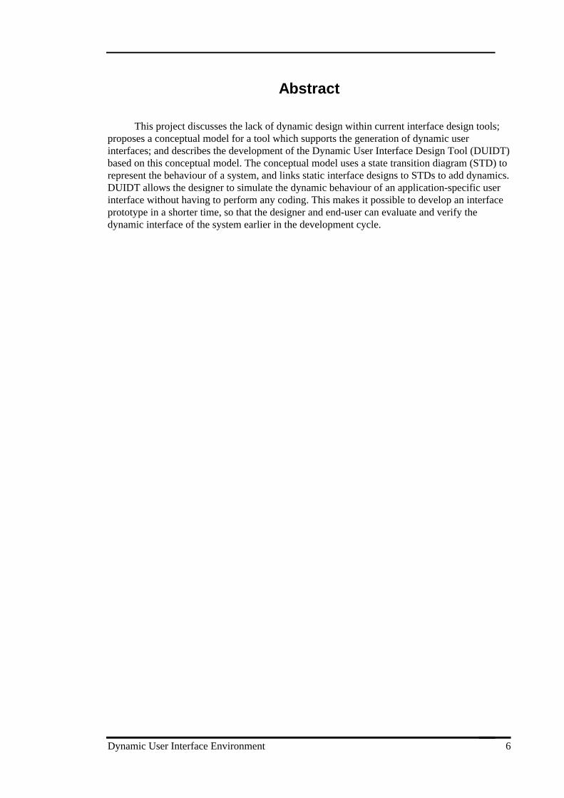
Abstract
This project discusses the lack of dynamic design within current interface design tools;proposes a conceptual model for a tool which supports the generation of dynamic userinterfaces; and describes the development of the Dynamic User Interface Design Tool (DUIDT)based on this conceptual model. The conceptual model uses a state transition diagram (STD) torepresent the behaviour of a system, and links static interface designs to STDs to add dynamics.DUIDT allows the designer to simulate the dynamic behaviour of an application-specific userinterface without having to perform any coding. This makes it possible to develop an interfaceprototype in a shorter time, so that the designer and end-user can evaluate and verify thedynamic interface of the system earlier in the development cycle.
Chapter 1 Introduction
Dynamic User Interface Environment 7
PART I INTRODUCTION
1. Introduction
In the early days of computer use, only a few computer specialists and professionalsinteracted with computer systems. However, in the last few years, as more non-specialists usecomputer systems in their work, a greater emphasis has been placed on effective user interfaces.Thus, the concept of a graphical user interface (GUI) was developed. The interface of mostmodern applications is based on the GUI interface because of the great advantages overcharacter-based interfaces.
Recent recognition of the importance and difficulty of GUI design in softwaredevelopment has prompted the development of many tools to help the interface designer. GUIdesign can be divided into two groups - dynamic and static. Static user interface tools representthe layout of windows and allow interface designers to create, display, and manipulate objectssuch as text, drawings, icons, and other graphic images. User Interface Design Builders such asDelphi, Visual Basic, etc. are examples of static user interface design tools. These buildersallow developers to build up the representation of interfaces quickly and to generate the screendesign code with ease. However, these builders have some limitations. Since most builderssupport only static screen design, difficulty arises when trying to define the dynamics of theinterface.
Dynamic means system behaviour as being derivable from the events that must be dealtwith. Dynamic user interface tools support developing the behaviour of the interface duringruntime by linking layout of interface design (representational aspects) to the functions of thesystem (operational aspects). While static user interface design is supported today by a widerange of visual programming tools, there are few dynamic user interface tools available despitethe importance of dynamic design.
The aim of this project is to propose a conceptual model for building a dynamic userinterface tool and to develop a tool based on this model. The dynamic aspects of user interfacescan be modelled through the use of state transition diagrams (STDs), which are conventionallyused to capture the behavioural viewpoint of a system. A STD can be produced for each classof the system to describe the dynamic behaviour of its instances. A STD is concerned withmodelling the dynamic aspects of the system in terms of entities such as states, events andconditions. The state represents an externally observable mode; the condition is an event in theexternal environment that the system is capable of detecting; and the action is the activity thatthe system invokes when it changes state. In order to add dynamics to a static user interface, themanipulation of window properties and events is needed. This can be achieved by linking staticwindow designs to STD conditions and actions.
The Dynamic User Interface Design Tool (DUIDT) has been developed to demonstratethe conceptual model suggested. DUIDT takes the output from a state transition diagram editor;gets user window designs from the user, links these to state transition diagram information; and,generates event handling code extending an existing static user interface design to adddynamics. The intended function of the generated event code is window navigation and contentsharing.
Chapter 1 Introduction
Dynamic User Interface Environment 8
DUIDT allows prototype user interfaces to be produced in a shorter time, and feedbackto be obtained from the developer and the potential end-user earlier in the development cycle.In addition, this tool reduces the development time of application-specific systems by allowingdynamic interfaces to be created without the designer having to write code, thus freeing theinterface designer from laborious and error-prone hand-coding.
The target potential user is a system developer, i.e., anyone who is responsible for GUIdevelopment. The implementation language is the JDK (Java Development Toolkit) 1.1 and theJava Delegation Event Model is adopted to handle events. The hardware used is a SUNWorkstation. The structured systems analysis and design, and GUIDE (Graphical User InterfaceDesign and Evaluation) methodologies are used for system and interface development,respectively. In addition, the client-server approach is used to store data in a database, i.e.,Oracle 7 is used as a database server and JDBC (Java Database Connectivity) is used to connectthe Java program to database.
The rest of the paper consists of three parts - background, tool development, andconclusion. Part II begins with background of user interfaces. The historical perspective of userinterfaces and the concept of graphical user interface (GUI) are briefly reviewed, and thecategories of user interface tools are classified. Chapter 3 gives an explanation of dynamicmodelling and of three types of state transition diagrams, and outlines briefly Mayerl, an STDeditor. Chapter 4 illustrates dynamic user interface tools and the lack of dynamic user interfacetool problem. In addition, Chapter 4 describes the conceptual model suggested to solve theperceived problem. Chapter 5 introduces a Keele Ferries Booking System which is used as arunning example. Chapters 6 and 7 describe the processes of the tool development and showsthe products of each development process stage. Chapter 8 presents the results and gives ananalytical evaluation of the project. Finally, Chapter 9 summarises the work done and theusefulness of the work, and suggests further work.
Dynamic User Interface Environment 9
PART II BACKGROUND
Part II introduces key concepts from the study of user interfaces and of dynamicmodelling, and briefly mentions the Mayerl STD editor for drawing state transition diagrams.The limitations of current GUI interface design tools will be discussed, and a conceptual modelof a dynamic interface design tool is suggested.
Chapter 2 User Interfaces
Dynamic User Interface Environment 10
2. User Interfaces
2.1 Historical Perspective of User Interfaces
The user interface is the part of a tool or system with which the user interacts directly.The user interface is also the user’s only means of accessing the inner functionality of thesystem. Since the use of computers has shifted from calculations or information processing to awider variety of applications, and the direct contact between the human and the computer hasbecome more and more advanced, the perspective of user interfaces and interaction styles hasbeen changed.
When a few computer specialists interacted with computer systems through punch cards,the user interface was of no concern because the end user did not interface directly with thecomputer system. Later, users were allowed to communicate directly with the computer systemthrough a terminal. Command-driven interfaces and form-fill applications are examples of thisprimitive user interface. Now, the user can communicate directly with computer system, and getfast feedback. However, command-driven interfaces caused problems in comprehension. In acommand-driven system, the user has to know what the allowable commands are and needs tohave a clear idea of the functions to be performed. In the last few years, as computer systemsare operated by more non-professional people as well as by professionals, the character-basedinterface was no longer usable and effective.
The purpose of designing new effective user interfaces was to make the computer systemmore usable for unskilled users. Thus, the graphical user interface (GUI) was developed.Whereas characters were the building blocks of command-driven interfaces, a component is abuilding block for GUIs. A component is a user interface object through which the usercommunicates, such as a label, text editor, push button and so on. Objects can be representedon the screen to appear in a physical form to be manipulated by the user directly (Shneiderman,1985). Most modern interfaces are developed using GUIs because well-designed systems with agraphical user interface are more usable - they are easier to learn, more effective to use andmore satisfying.
2.2 Graphical User Interfaces (GUIs)
The central components of most Graphic User Interface (GUI) systems are a set ofwindows and components.
2.2.1 Window
A window is a communication channel through which the user looks to see and interactwith the objects in the system. Typically, a window has a frame (borders), which defines itsboundary, and titles; and performs various functions (such as opening, closing, moving,resizing, minimising to an iconic form, and maximising to fill the current screen). Each windowcontains one or more components, through which the users communicates with the system, anda set of window actions. A window action is an action the user can perform on a component(e.g. click a button, edit text in a text edit control, dragging and dropping an icon) in order toachieve some effect (e.g. displaying information in the window, moving to another window).Most modern interfaces allow several windows to be displayed at one time.
Chapter 2 User Interfaces
Dynamic User Interface Environment 11
2.2.2 Component1
A component is a user interface object through which the user communicates, and it cancorrespond in appearance to some objects which can be manipulated. Different environmentshave different component sets. However, a number of them contain similar kinds ofcomponents, so that one can think of a generic component set which is applicable to mostinterfaces. For example, menu, label, text edit, push button and checkbox are components thatare available in most environments.
Components have three basic functions:
• to allow the user to perform actions
• to allow the user to see the state of the objects in the system
• to allow the user to enter data.
Simple components may be limited to just one of the above functions; more complexcomponents allow the user to perform two or all three functions. For instance, a text editcomponent is an example of a control used to display and enter data; a push button componentis an example of a control used by the user to perform an action.
2.2.3 Event-based interface
The GUI can be viewed as a collection of events and event handlers. From the userinterface point of view, windowing systems are principally driven by asynchronous eventsgenerated by the user. An event is an unexpected, external happening that imposes itself oncomponents. The component looks for certain events which can occur through the peripheralinput devices (Most computer systems use two basic input devices: the keyboard and a mouse).Component events could be any of the following: typing any key, moving the mouse cursor intoor out of a window, pressing the mouse button, releasing the mouse button, and clicking on amouse button, and so on. User actions give rise to events which are then passed to thosehandlers that have indicated they will handle them. If an event occurs in a component which thecomponent is not looking for, then that event will be ignored. Some components might not havemany relevant events. For example, a label component usually does nothing except provide alabel for another component.
2.3 User Interface Tools
Any computer program used to design, make, maintain, manage, or test a softwareproduct can be called a software tool. Effective tools provide the benefits of increasedproductivity, enhanced software quality, and easier and better management of softwaredevelopment. In terms of the user interfaces of today’s software systems, the user interfaceitself is large and complex, and the manipulation of windows can remain as a distraction fromthe user’s tasks. Therefore, user interface tools are needed as with most software tools. Inaddition, a description on paper has a number of limitations. It cannot show the full dynamic
1 A component is also called a widget, a gadget, a control, an interactors, or a GUI elementaccording to environments. The term component will be used throughout the paper.
Chapter 2 User Interfaces
Dynamic User Interface Environment 12
properties of the user interface, and it may not be able to communicate the true nature of theapplication to people outside the design team. Furthermore, the cycle of enhancement andevaluation is likely to be slowed down by documenting all details of each stage on paper. Forthese and other reasons it is common to use prototyping tools to describe ideas for userinterface designs. Once described in this way, the designs can be tested directly, without theneed to wait while they are implemented.2
The benefits provided by interface design tools are:
• Better communication with the user : The user can obtain early hands-on experience of howthe GUI will look, feel and perform. They can assess earlier how it will impact theirbusiness.
• Improved design through feedback and iteration : The iterative nature of the approachmeans that a number of different approaches can be evaluated with the user, and theirfeedback used to evolve and improve the design.
• Reduced risk : The risk of producing an unsuitable GUI is greatly reduced.
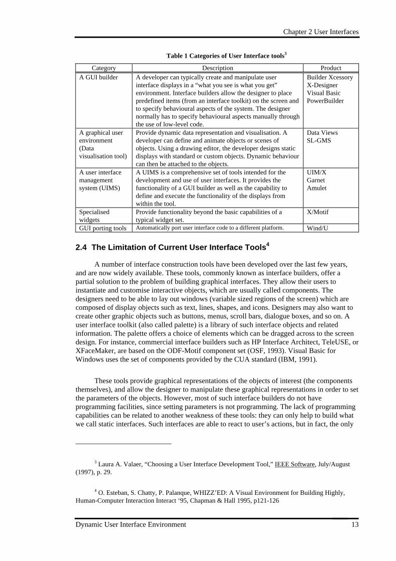
There are a number of tools for various purposes. Some of the most widely advertisedtype of GUI tools are shown in Table 1. Many of GUI tools have functionality that place themin more than one category. One example is a GUI builder that also provides support fordynamic data visualisation.
2 William M. Newman & Michael G. Lamming, Interactive System Design, (Addison-Wesley,1995), p. 287.
Chapter 2 User Interfaces
Dynamic User Interface Environment 13
Table 1 Categories of User Interface tools3
Category Description Product
A GUI builder A developer can typically create and manipulate userinterface displays in a “what you see is what you get”environment. Interface builders allow the designer to placepredefined items (from an interface toolkit) on the screen andto specify behavioural aspects of the system. The designernormally has to specify behavioural aspects manually throughthe use of low-level code.
Builder XcessoryX-DesignerVisual BasicPowerBuilder
A graphical userenvironment(Datavisualisation tool)
Provide dynamic data representation and visualisation. Adeveloper can define and animate objects or scenes ofobjects. Using a drawing editor, the developer designs staticdisplays with standard or custom objects. Dynamic behaviourcan then be attached to the objects.
Data ViewsSL-GMS
A user interfacemanagementsystem (UIMS)
A UIMS is a comprehensive set of tools intended for thedevelopment and use of user interfaces. It provides thefunctionality of a GUI builder as well as the capability todefine and execute the functionality of the displays fromwithin the tool.
UIM/XGarnetAmulet
Specialisedwidgets
Provide functionality beyond the basic capabilities of atypical widget set.
X/Motif
GUI porting tools Automatically port user interface code to a different platform. Wind/U
2.4 The Limitation of Current User Interface Tools4
A number of interface construction tools have been developed over the last few years,and are now widely available. These tools, commonly known as interface builders, offer apartial solution to the problem of building graphical interfaces. They allow their users toinstantiate and customise interactive objects, which are usually called components. Thedesigners need to be able to lay out windows (variable sized regions of the screen) which arecomposed of display objects such as text, lines, shapes, and icons. Designers may also want tocreate other graphic objects such as buttons, menus, scroll bars, dialogue boxes, and so on. Auser interface toolkit (also called palette) is a library of such interface objects and relatedinformation. The palette offers a choice of elements which can be dragged across to the screendesign. For instance, commercial interface builders such as HP Interface Architect, TeleUSE, orXFaceMaker, are based on the ODF-Motif component set (OSF, 1993). Visual Basic forWindows uses the set of components provided by the CUA standard (IBM, 1991).
These tools provide graphical representations of the objects of interest (the componentsthemselves), and allow the designer to manipulate these graphical representations in order to setthe parameters of the objects. However, most of such interface builders do not haveprogramming facilities, since setting parameters is not programming. The lack of programmingcapabilities can be related to another weakness of these tools: they can only help to build whatwe call static interfaces. Such interfaces are able to react to user’s actions, but in fact, the only
3 Laura A. Valaer, “Choosing a User Interface Development Tool,” IEEE Software, July/August(1997), p. 29.
4 O. Esteban, S. Chatty, P. Palanque, WHIZZ’ED: A Visual Environment for Building Highly,Human-Computer Interaction Interact ‘95, Chapman & Hall 1995, p121-126
Chapter 2 User Interfaces
Dynamic User Interface Environment 14
difference from static screens lies in predefined behaviours, which can hardly be changed.Creating more dynamic and highly interactive interfaces, requires more than the instantiationand parameterization of predefined components. In fact, some of the interface builders offerfacilities for reprogramming or enriching the behaviour of their components. But for thispurpose, they provide specialised textual programming languages whose manipulation requirestraditional programming skills.
Chapter 3 Dynamic Modelling
Dynamic User Interface Environment 15
3. Dynamic Modelling
3.1 The Dynamic View of a System
Software development usually involves modelling and describing its behaviour as well asits structure, and also the functions that it will perform. That is, the system view can becategorised into three viewpoints - functional, structural, and behavioural (dynamic). Thedynamic viewpoint of the system is captured by dynamic modelling which is used to analyseand describe the dynamic behaviour. Dynamic modelling is useful where there is significantstate-dependent behaviour, i.e., where the behaviour of an object changes through time,depending on the state that the object is in.
Since the dynamic behaviour is sometimes complex and difficult to understand, it isimportant to have an appropriate diagrammatic notation to help visualise the behaviour. Thoughthere are several such representations of a behavioural view, a state transition diagram (alsocalled finite state or state diagram) is the most widely used and well-known notation. The statetransition diagram (STD) is concerned with modelling the dynamic attributes of the system, interms of entities such as states, events, and conditions.
3.2 State Transition Diagrams
The state transition diagram describes the temporal evolution of an object of a givenclass in response to interactions with other objects either inside or outside the system. Itprovides a convenient means for modelling many systems which have an event-driven nature.There are a number of different extended methods but the main idea is the same. Threerepresentative diagrams will be considered in a little more detail.
3.2.1 The State Transition Diagram (STD) - Ward and Mellor (1985)5
The components are the state, represented by a rectangle; the transition, represented byan arrow with a horizontal line; the transition condition, shown adjacent to the transition abovethe line; and the transition action, shown adjacent to the transition below the line. A staterepresents an externally observable mode of behaviour. There are two special types of state -initial and final states. The initial state is the state of the system before any transitions haveoccurred. A final state should be thought of as a ‘dead end’ in the behaviour of the system. Atransition represents the movement from one state to another. Transitions can exist between anystate and any other state, including the state from which the transition started. Multipletransitions to and from a given state are permissible. The transition condition identifies thecondition that will cause the transition to occur - usually in terms of the event that caused thetransition. The transition action is the action that arises as a result of the transition. Severalindependent actions may be taken on a single transition simultaneously, or in a specificsequence.
5 Paul T. Ward & Stephen J. Mellor, Structured Development for Real-Time Systems, (YourdonPress, Prentice-Hall, 1985).
Chapter 3 Dynamic Modelling
Dynamic User Interface Environment 16
The STD (also called flat state machine) is a useful modelling tool and has been widelyused to model real-time systems. However, the principal disadvantage of the technique is that ifmany transitions are permitted between a small number of states, the diagram can become verytangled. Similarly, large and complex systems lead to large and complex diagrams because ofthe STD’s lack of hierarchy.
Figure 1 Example of state transition diagram - (Ward & Mellor, 1985, p68)
3.2.2 The Statechart - David Harel (1987; 1988)6
David Harel’s statechart is a major advance on the limitation of traditional flat statemachines. Like the STD, the statechart is concerned with providing a behavioural description ofa system. However, it provides a rather more abstract and modular form of description than theSTD, by enabling hierarchy, orthogonality (i.e., concurrency), and encouraging ‘zoom’capabilities for moving easily back and forth between different levels of abstraction. The abilityto create a hierarchy of abstraction enables viewing the description at different levels of detail,and make even very large specifications manageable and comprehensible. Concurrency permitsthe designer to describe transitions that are orthogonal in that they are completely independentof each other. This makes it possible to easily describe synchronised behaviours.
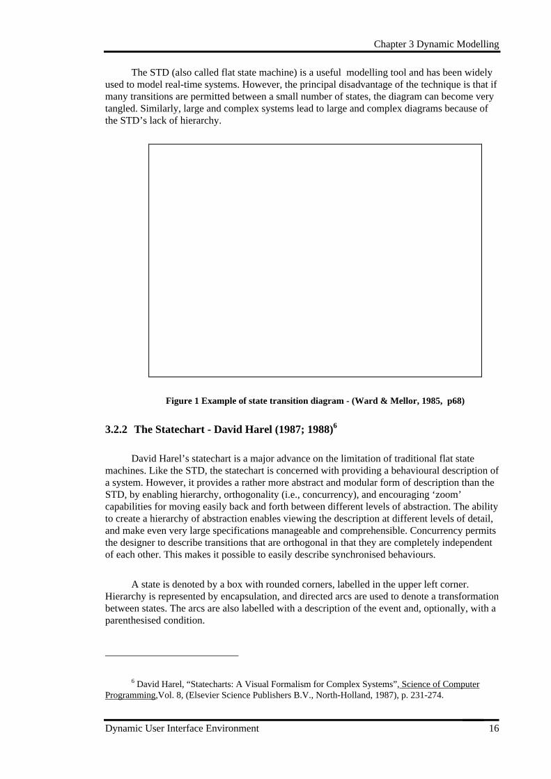
A state is denoted by a box with rounded corners, labelled in the upper left corner.Hierarchy is represented by encapsulation, and directed arcs are used to denote a transformationbetween states. The arcs are also labelled with a description of the event and, optionally, with aparenthesised condition.
6 David Harel, “Statecharts: A Visual Formalism for Complex Systems”, Science of ComputerProgramming,Vol. 8, (Elsevier Science Publishers B.V., North-Holland, 1987), p. 231-274.
Chapter 3 Dynamic Modelling
Dynamic User Interface Environment 17
Citizen quartz multi-alarm III
alive dead
batt. removed
batt. inserted
weak batt. dies
Figure 2 Example of statechart - (Harel, 1987, p246)
Two elements of the statechart -hierarchy and concurrency, allow statecharts to becompact and expressive, i.e., small diagrams can express complex behaviour. The statechart isthus increasingly accepted as the most powerful form of dynamic modelling for object-orientedanalysis. The difference between the statechart and the STD is that the statechart has morerefined mechanisms for describing abstraction, while the STD provides a more detaileddescription in terms of the actions that occur. In that sense, they are largely complementaryrather than alternative. The statechart is perhaps more suited to modelling problems, and theSTD better suited for modelling detailed solutions.
3.2.3 State Diagram - UML (Unified Modelling Language)7
The semantics and notation of state diagrams described in the UML Notation Guide aresubstantially those of David Harel’s statechart with some modifications. A state diagram showsthe sequence of states that an object or an interaction goes through during its life in response toreceived stimuli, together with its responses and actions.
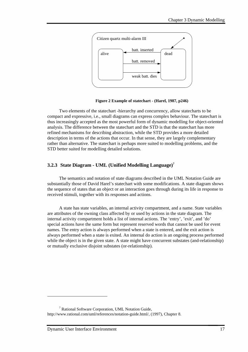
A state has state variables, an internal activity compartment, and a name. State variablesare attributes of the owning class affected by or used by actions in the state diagram. Theinternal activity compartment holds a list of internal actions. The ‘entry’, ’exit’, and ’do’special actions have the same form but represent reserved words that cannot be used for eventnames. The entry action is always performed when a state is entered, and the exit action isalways performed when a state is exited. An internal do action is an ongoing process performedwhile the object is in the given state. A state might have concurrent substates (and-relationship)or mutually exclusive disjoint substates (or-relationship).
7 Rational Software Corporation, UML Notation Guide,http://www.rational.com/uml/references/notation-guide.html/, (1997), Chapter 8.
Chapter 3 Dynamic Modelling
Dynamic User Interface Environment 18
Typing password
password: String = ““fails: Integer = 0
entry/set echo invisibleexit/set echo normaldo/echo typinghelp/display help
Figure 3 A state of State Diagram
As an alternative to showing actions on transitions, actions can be associated withentering or exiting a state. There is no difference in expressive power between the twonotations, but frequently all transitions into a state perform the same action, in which caseattaching the action to the state is more concise. An ‘entry’ action is shown inside the state boxfollowing the keyword entry and a “/” character. Whenever the state is entered, by anyincoming transition, the entry action is performed. An ‘entry’ action is equivalent to attachingthe action to every incoming transition. If an incoming transition already has an action, itsaction is performed first. An ‘exit’ action is shown inside the state box following the keyword‘exit’ and a ‘/’ character. Whenever the state is exited, by any outgoing transition, the ‘exit’action is performed first. If multiple operations are specified on a state, they are performed inthe following order: actions on the incoming transition, ‘entry’ actions, ‘do’ activities, ‘exit’actions, actions on the outgoing transition. ‘do’ activities can be interrupted by events thatcause transitions out of state, but entry actions and exit actions are completed regardless, sincethey are considered to be instantaneous actions. If a ‘do’ activity is interrupted, the ‘exit’ actionis nevertheless performed. Moving into or out of a substate in a nested diagram can causeexecution of several ‘entry’ or ‘exit’ actions, if the transition reaches across several levels ofgeneralisation. The ‘entry’ actions are executed from the outside in and the exit actions fromthe inside out.
‘Entry’ and ‘exit’ actions are particularly useful in nested state diagrams because theypermit a state to be expressed in terms of matched entry-exit actions without regard for whathappens before or after the state is active.8
A simple transition is a relationship between two states indicating that an object in thefirst state will enter the second state and perform a certain specified action when a specifiedevent occurs and the specified condition is satisfied. This transition is shown as a solid arrowfrom one state to another state labelled with a transition string. The string has the followingformat:
event-signature [ guard-condition] / action-expression ^ send-clause
8 J. Rumbaugh & M. Blaha, etc., Object-Oriented Modelling and Design, (Prentice-Hall, 1991).
Chapter 3 Dynamic Modelling
Dynamic User Interface Environment 19
A complex transition may have multiple source states and target states. It is shown as ashort heavy vertical bar. A self-transition is from a state back to the same state. The self-transition causes the exit and entry actions on the state to be executed and the initial state to beentered.
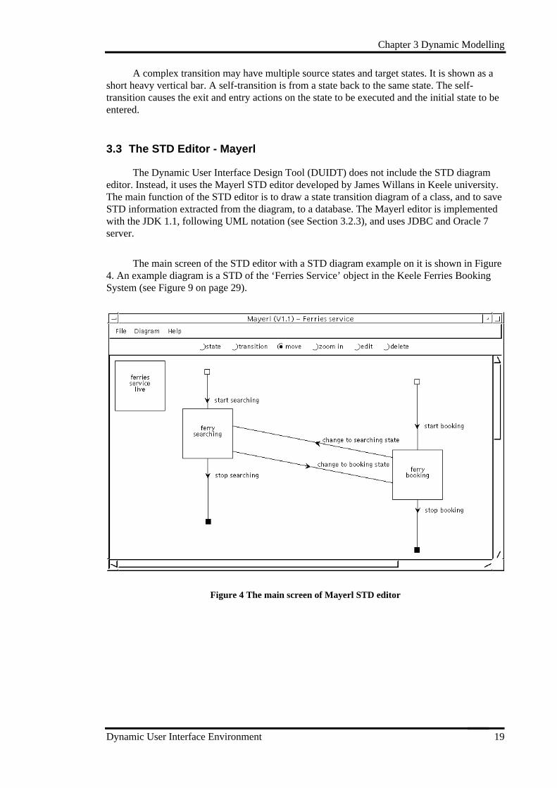
3.3 The STD Editor - Mayerl
The Dynamic User Interface Design Tool (DUIDT) does not include the STD diagrameditor. Instead, it uses the Mayerl STD editor developed by James Willans in Keele university.The main function of the STD editor is to draw a state transition diagram of a class, and to saveSTD information extracted from the diagram, to a database. The Mayerl editor is implementedwith the JDK 1.1, following UML notation (see Section 3.2.3), and uses JDBC and Oracle 7server.
The main screen of the STD editor with a STD diagram example on it is shown in Figure4. An example diagram is a STD of the ‘Ferries Service’ object in the Keele Ferries BookingSystem (see Figure 9 on page 29).
Figure 4 The main screen of Mayerl STD editor
Chapter 4 Dynamic Interfaces
Dynamic User Interface Environment 20
4. Dynamic Interfaces
4.1 Issues Raised by Interface Building
Graphical interfaces have static and dynamic properties. The static properties are simplythe graphical appearance of a system (representational aspects). The dynamic properties are theunderlying functional behaviour of the user interface specification (static interface). Dynamicproperties can be represented much better and tested more effectively with an executableprototype than is the case with other means of representation.
Problems with current design tools for the generation of user interfaces are poor facilitiesfor specification of dynamic behaviour and poor integration between generation tools and GUIbuilders. The user interface layout specification specifies the static layout, but withoutconsidering the dynamic behaviour. GUI builders often have no appropriate specificationlanguage. Only direct code generation and internal layout representations are possible in mostcases. However, within todays graphical user interfaces (GUIs), a large number of closelycoupled dynamic effects exist. Actually, the most important aspect during the development of aprototype for exploring the user’s requirements is not the layout of the user interface but itsdynamic behaviour. The complexity of an interactive application actually lies in the behaviourof graphical objects, and in the many interrelations between them.(Myers et al., 1990). Forinstance, a real-time monitoring and control system typically requires graphical displays toimprove understandability. The dynamic characteristics of these displays help users performtheir required activities more efficiently. In addition, even when the static structure of aprogram is complete, the correctness of its dynamic behaviour still needs to be confirmed. Thisneed to keep both static form and eventual dynamic behaviours continually in mind whendeveloping interfaces of a system.
Another point is that the design of an interactive application interface usually involveshuman factors specialists, future users of the application, and occasionally graphics designers.These people usually do not have an education in computer science, and most of them have torely on highly specialised programmers for building prototypes of the system they aredesigning. Furthermore, the design of efficient and usable interfaces requires many iterations ofthe design and evaluation of prototypes. As long as complex programming is necessary, thedevelopment of a system with a high quality and better interface will be very costly.
Despite the importance of dynamic design, much less support is available for thedynamic part of a GUI. The development of graphical user interfaces with application-specificappearance and behaviour is still a challenge not met by current tools. One possible reason forthis is that it is quite difficult to generalise the functions of a dynamic tool because of itsbusiness-specific characteristics. Thus the challenge here consists of providing easy-to-useprogramming design facilities, so that interface designers can build highly interactiveapplications or prototypes rapidly.
4.2 The Conceptual Model
In design builders, the way dynamics are added into the interface design is that theinterface designer manipulates component attributes and specifies reaction routines by hand.The process of developing dynamic user interfaces may be improved by combining formalspecifications of the dynamic behaviour with interactive layout specifications of the static
Chapter 4 Dynamic Interfaces
Dynamic User Interface Environment 21
appearance of user interfaces (Lauridsen, 1995). Therefore, I present here a conceptual modelwhich allows the designer to create application-specific dynamic user interfaces automatically.
The conceptual model is based on the ‘object-oriented’ ideas, i.e., the organisation andbehaviour of user interface are object-oriented. The model considers static interfaces (theappearance of windows) as views of user classes allocated to the window components, and thebehaviour of interface as the action of classes identified in the system. This approach provides auseful basis for the definition of windows, and promotes an object-action style of user interface.
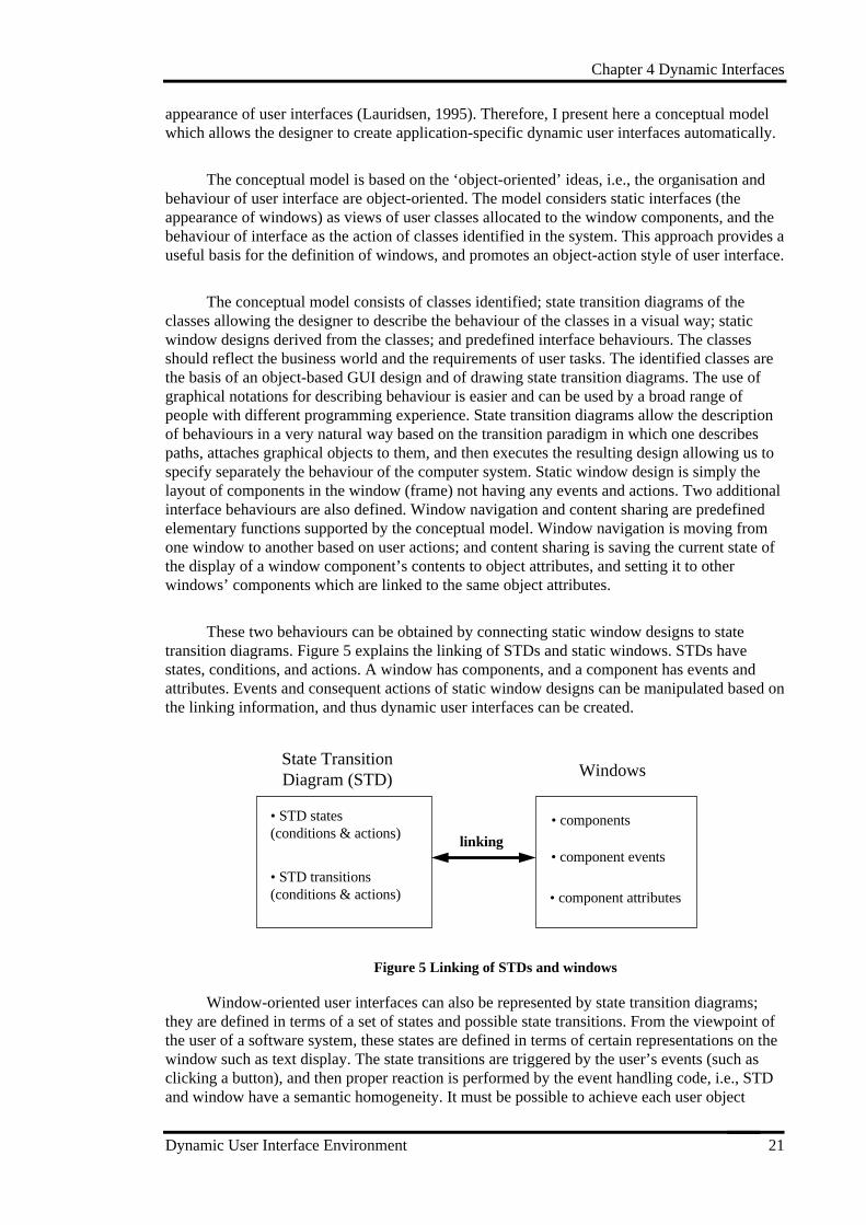
The conceptual model consists of classes identified; state transition diagrams of theclasses allowing the designer to describe the behaviour of the classes in a visual way; staticwindow designs derived from the classes; and predefined interface behaviours. The classesshould reflect the business world and the requirements of user tasks. The identified classes arethe basis of an object-based GUI design and of drawing state transition diagrams. The use ofgraphical notations for describing behaviour is easier and can be used by a broad range ofpeople with different programming experience. State transition diagrams allow the descriptionof behaviours in a very natural way based on the transition paradigm in which one describespaths, attaches graphical objects to them, and then executes the resulting design allowing us tospecify separately the behaviour of the computer system. Static window design is simply thelayout of components in the window (frame) not having any events and actions. Two additionalinterface behaviours are also defined. Window navigation and content sharing are predefinedelementary functions supported by the conceptual model. Window navigation is moving fromone window to another based on user actions; and content sharing is saving the current state ofthe display of a window component’s contents to object attributes, and setting it to otherwindows’ components which are linked to the same object attributes.
These two behaviours can be obtained by connecting static window designs to statetransition diagrams. Figure 5 explains the linking of STDs and static windows. STDs havestates, conditions, and actions. A window has components, and a component has events andattributes. Events and consequent actions of static window designs can be manipulated based onthe linking information, and thus dynamic user interfaces can be created.
State TransitionDiagram (STD) Windows
• component events
• STD states(conditions & actions) linking
• components
• component attributes
• STD transitions(conditions & actions)
Figure 5 Linking of STDs and windows
Window-oriented user interfaces can also be represented by state transition diagrams;they are defined in terms of a set of states and possible state transitions. From the viewpoint ofthe user of a software system, these states are defined in terms of certain representations on thewindow such as text display. The state transitions are triggered by the user’s events (such asclicking a button), and then proper reaction is performed by the event handling code, i.e., STDand window have a semantic homogeneity. It must be possible to achieve each user object
Chapter 4 Dynamic Interfaces
Dynamic User Interface Environment 22
action using window events, such as pressing a button, editing a component, selecting a menu,double-clicking. etc. This characteristic makes it natural to link window events to STD events(also called STD conditions); and link window actions to STD actions.
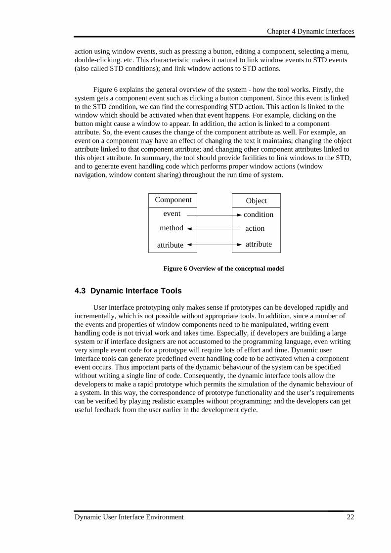
Figure 6 explains the general overview of the system - how the tool works. Firstly, thesystem gets a component event such as clicking a button component. Since this event is linkedto the STD condition, we can find the corresponding STD action. This action is linked to thewindow which should be activated when that event happens. For example, clicking on thebutton might cause a window to appear. In addition, the action is linked to a componentattribute. So, the event causes the change of the component attribute as well. For example, anevent on a component may have an effect of changing the text it maintains; changing the objectattribute linked to that component attribute; and changing other component attributes linked tothis object attribute. In summary, the tool should provide facilities to link windows to the STD,and to generate event handling code which performs proper window actions (windownavigation, window content sharing) throughout the run time of system.
Component Object
event
method
attribute
condition
action
attribute
Figure 6 Overview of the conceptual model
4.3 Dynamic Interface Tools
User interface prototyping only makes sense if prototypes can be developed rapidly andincrementally, which is not possible without appropriate tools. In addition, since a number ofthe events and properties of window components need to be manipulated, writing eventhandling code is not trivial work and takes time. Especially, if developers are building a largesystem or if interface designers are not accustomed to the programming language, even writingvery simple event code for a prototype will require lots of effort and time. Dynamic userinterface tools can generate predefined event handling code to be activated when a componentevent occurs. Thus important parts of the dynamic behaviour of the system can be specifiedwithout writing a single line of code. Consequently, the dynamic interface tools allow thedevelopers to make a rapid prototype which permits the simulation of the dynamic behaviour ofa system. In this way, the correspondence of prototype functionality and the user’s requirementscan be verified by playing realistic examples without programming; and the developers can getuseful feedback from the user earlier in the development cycle.
Dynamic User Interface Environment 23
PART III TOOL DEVELOPMENT
Part III introduces a business system development used as an example of dynamicinterface design. Dynamic User Interface Design Tool (DUIDT) has been developed using twomethodologies. Chapter 6 shows the development process and products for system developmentbased on the Structured System Analysis and Design Methodology. The functionality and datastructures of the system, the structure of the objects that constitute the system, and theoperational aspects of the system are covered here. Since DUIDT has a GUI, it is necessary touse an interface development methodology. That is, the user interface of the user interfacedesign tool needs to be designed following an interface methodology. The Graphical UserInterface Design and Evaluation (GUIDE)9 methodology is used to develop the interface of thesystem. Chapter 7 describes the representational aspects of the system (the form and content ofthe windows) and documents the processes and products of each interface development stage.
9 D. Redmond-Pyle & A. Moore, Graphical User Interface Design and Evaluation, (Prentice-Hall,1995).
Chapter 5 Example - Keele Ferries Booking System
Dynamic User Interface Environment 24
5. Example - Keele Ferries Booking System
This chapter introduces an example of a GUI system development, which is used as arunning example through the tool development. This simple example is used to illustrate andtest how the dynamic user interface design tool works. The example is a Keele ferries bookingsystem based on a fictitious GUI design project.10 The project is conducted following theGUIDE methodology (D. Redmond & A. Moore, 1995). The GUIDE methodology will beexplained in detail in Section 7.1.
Since the main purpose of the example is to test and to demonstrate the DUIDT, thedesign processes will be simplified as much as possible. That is, the irrelevant systemdevelopment procedures such as data structures, business processes, etc. and even some GUIdesign processes, which are not directly relevant, will not be discussed. Instead, the designwork focuses on task scenarios, dynamic modelling, and user interface designs (windowdesign).
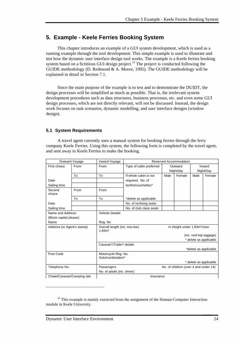
5.1 System Requirements
A travel agent currently uses a manual system for booking ferries through the ferrycompany Keele Ferries. Using this system, the following form is completed by the travel agent,and sent away to Keele Ferries to make the booking.
Outward Voyage Inward Voyage Reserved Accommodation
First choice From From Type of cabin preferred OutwardNight/day
InwardNight/Day
To To If whole cabin is not Male Female Male Female
Date required. No. of
Sailing time berths/couchettes*
Secondchoice
From From
To To *delete as applicable
Date No. of reclining seats
Sailing time No. of club class seats
Name and Address(Block capital please)
Vehicle Details
Name Reg. No
Address (or Agent’s stamp) Overall length (inc. tow-bar) m Height under 1.83m*/over1.83m*
(inc. roof-top luggage)* delete as applicable
Caravan*/Trailer* details*delete as applicable
Post Code Motorcycle Reg. No.Solo/combination*
* delete as applicable
Telephone No. Passengers No. of children (over 4 and under 14)No. of adults (inc. driver)
Chalet/Caravan/Camping site Insurance
10 This example is mainly extracted from the assignment of the Human-Computer Interactionmodule in Keele University.
Chapter 5 Example - Keele Ferries Booking System
Dynamic User Interface Environment 25
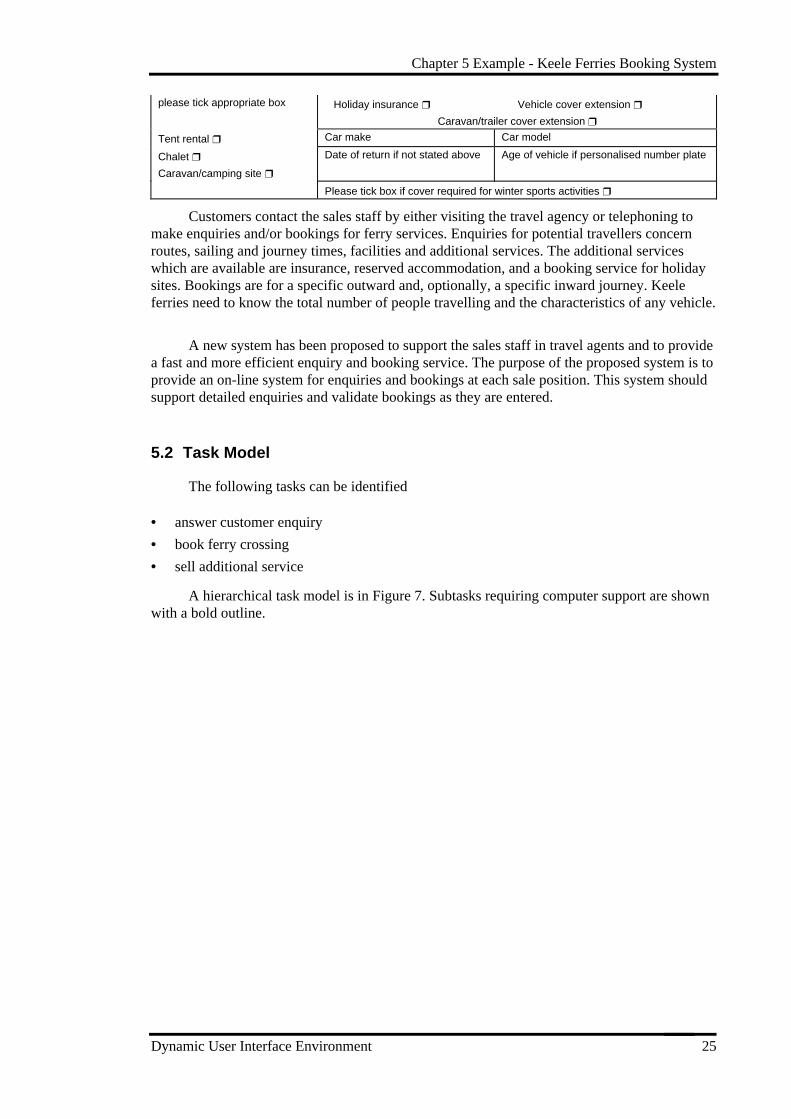
please tick appropriate box Holiday insurance ❒ Vehicle cover extension ❒
Caravan/trailer cover extension ❒
Tent rental ❒ Car make Car model
Chalet ❒
Caravan/camping site ❒
Date of return if not stated above Age of vehicle if personalised number plate
Please tick box if cover required for winter sports activities ❒
Customers contact the sales staff by either visiting the travel agency or telephoning tomake enquiries and/or bookings for ferry services. Enquiries for potential travellers concernroutes, sailing and journey times, facilities and additional services. The additional serviceswhich are available are insurance, reserved accommodation, and a booking service for holidaysites. Bookings are for a specific outward and, optionally, a specific inward journey. Keeleferries need to know the total number of people travelling and the characteristics of any vehicle.
A new system has been proposed to support the sales staff in travel agents and to providea fast and more efficient enquiry and booking service. The purpose of the proposed system is toprovide an on-line system for enquiries and bookings at each sale position. This system shouldsupport detailed enquiries and validate bookings as they are entered.
5.2 Task Model
The following tasks can be identified
• answer customer enquiry
• book ferry crossing
• sell additional service
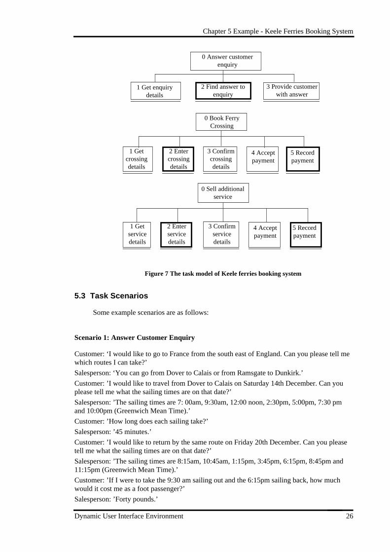
A hierarchical task model is in Figure 7. Subtasks requiring computer support are shownwith a bold outline.
Chapter 5 Example - Keele Ferries Booking System
Dynamic User Interface Environment 26
0 Answer customerenquiry
1 Get enquirydetails
2 Find answer toenquiry
3 Provide customerwith answer
0 Book FerryCrossing
1 Getcrossingdetails
2 Entercrossingdetails
3 Confirmcrossingdetails
4 Acceptpayment
5 Recordpayment
0 Sell additionalservice
1 Getservicedetails
2 Enterservicedetails
3 Confirmservicedetails
4 Acceptpayment
5 Recordpayment
Figure 7 The task model of Keele ferries booking system
5.3 Task Scenarios
Some example scenarios are as follows:
Scenario 1: Answer Customer Enquiry
Customer: ‘I would like to go to France from the south east of England. Can you please tell mewhich routes I can take?’
Salesperson: ‘You can go from Dover to Calais or from Ramsgate to Dunkirk.’
Customer: ’I would like to travel from Dover to Calais on Saturday 14th December. Can youplease tell me what the sailing times are on that date?’
Salesperson: ’The sailing times are 7: 00am, 9:30am, 12:00 noon, 2:30pm, 5:00pm, 7:30 pmand 10:00pm (Greenwich Mean Time).’
Customer: ’How long does each sailing take?’
Salesperson: ’45 minutes.’
Customer: ’I would like to return by the same route on Friday 20th December. Can you pleasetell me what the sailing times are on that date?’
Salesperson: ’The sailing times are 8:15am, 10:45am, 1:15pm, 3:45pm, 6:15pm, 8:45pm and11:15pm (Greenwich Mean Time).’
Customer: ’If I were to take the 9:30 am sailing out and the 6:15pm sailing back, how muchwould it cost me as a foot passenger?’
Salesperson: ’Forty pounds.’
Chapter 5 Example - Keele Ferries Booking System
Dynamic User Interface Environment 27
Customer: ‘If I were to take holiday insurance as well, how much would that cost me?’
Salesperson: ’An additional fifteen pounds.’
Scenario 2: Book Ferry Crossing
Customer: ’I would like to book a return ferry crossing from Dover to Calais as a footpassenger, leaving at 9:30am on Saturday 14th December, and returning at 6:15pm on Friday20th December.’
Salesperson: ’Can you give me your name and address please?’
Customer: ’Joe Bloggs, 22 Acacia Avenue, London.’
Salesperson: ’Can you give me your post code please?’
Customer: ’SW1 1AA’
Salesperson: ’Can you give me your daytime telephone number please?’
Customer: ’0171 1234567’
Salesperson: (Enters details) ’Can I just confirm you will be sailing from Dover to Calais as afoot passenger at 9:30am on Saturday 14th December, and returning at 6:15 pm on Friday 20thDecember.’
Customer: ‘That is correct’
Salesperson: ’That will be forty pound please.’ (Accepts payment and records the fact that ithas been made).
Scenario 3: Sell Additional Service
Salesperson: ’Would you like to buy holiday insurance?’
Customer: ’Yes please’
Salesperson: ’That will be fifteen pounds please.’ (Accepts payment and records the fact that ithas been made).
5.4 User Object Model
The system has four objects - customer, ferries service, insurance, and holiday sitesservice. The attributes and actions of each object are as follows.
Customer
Attribute ActionSSN (to identify a customer)nameaddresspost codephone number
create a customer instancechange personal details
Chapter 5 Example - Keele Ferries Booking System
Dynamic User Interface Environment 28
Ferries Service
Attribute Actionferry registration numberport from (port name)port todatetimesailing timelist of fares (foot passenger, cabin, vehicle...)ferry details (capacity, ...)occupied details (no. of booked passengers, vehicles... )
ferry service createdreserve a placerelease(cancel) a booked placeservice searchedchange availability statusferry service deleted
Insurance
Attribute Actionnamepricedescription
create a servicechange service details (price, condition, ...)delete a service
Holiday sites Service
Attribute Actionsite identification numberavailability statussite details (type, price, capacity, location,...)occupied details
holiday site service createdreserve a siterelease a reserved sitesearch for price, location, availabilityholiday site service deleted
5.5 Object Relationships
Figure 8 Object relationships
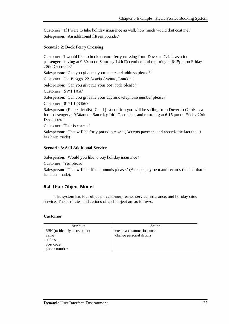
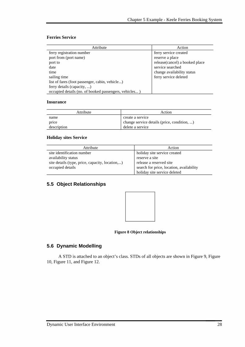
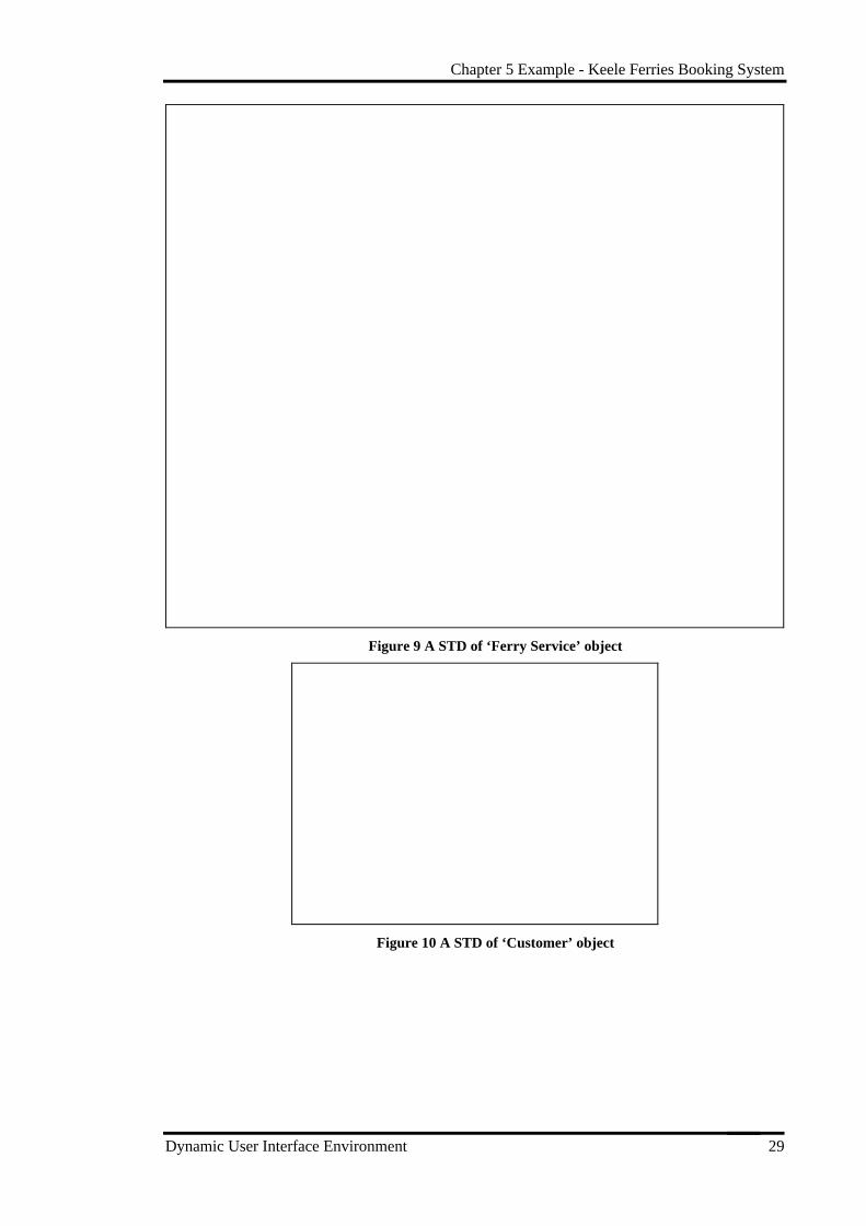
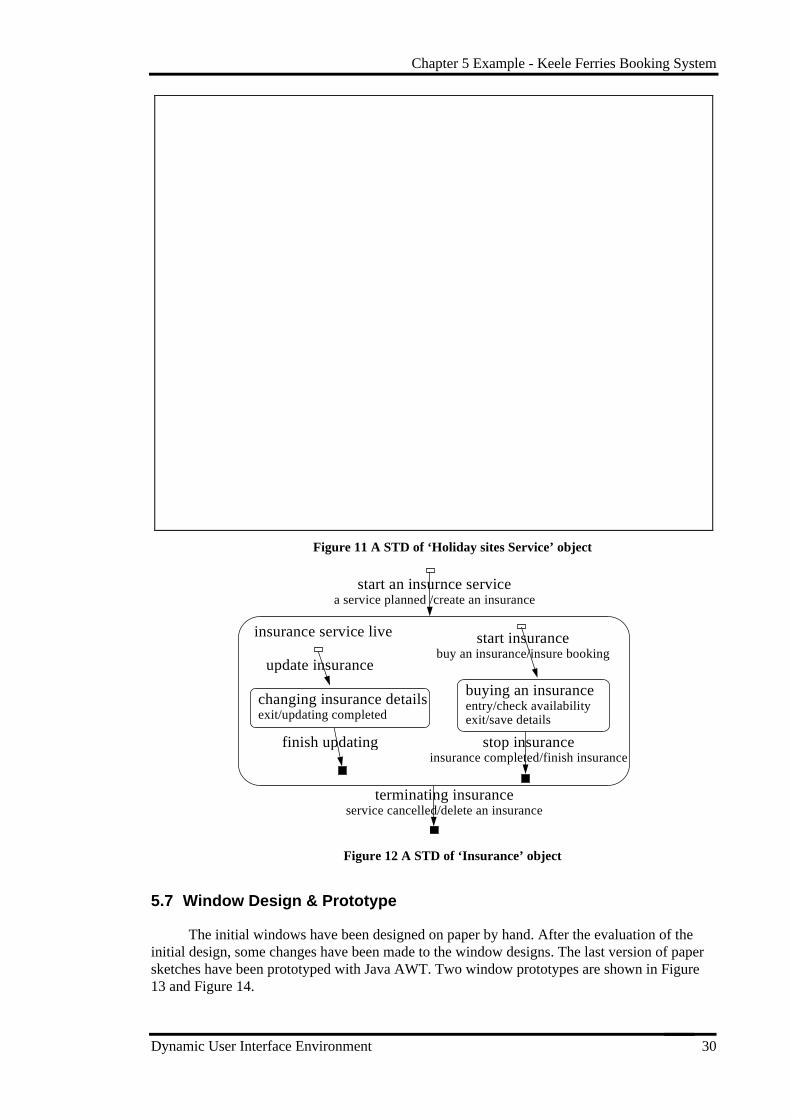
5.6 Dynamic Modelling
A STD is attached to an object’s class. STDs of all objects are shown in Figure 9, Figure10, Figure 11, and Figure 12.
Chapter 5 Example - Keele Ferries Booking System
Dynamic User Interface Environment 29
Figure 9 A STD of ‘Ferry Service’ object
Figure 10 A STD of ‘Customer’ object
Chapter 5 Example - Keele Ferries Booking System
Dynamic User Interface Environment 30
Figure 11 A STD of ‘Holiday sites Service’ object
insurance service li ve
buying an insuranceentry/check availabil ityexit/save details
terminating insuranceservice cancelled/delete an insurance
start an insurnce servicea service planned /create an insurance
changing insurance detail sexit/updating completed
start insurancebuy an insurance/insure booking
update insurance
finish updating stop insuranceinsurance completed/finish insurance
Figure 12 A STD of ‘Insurance’ object
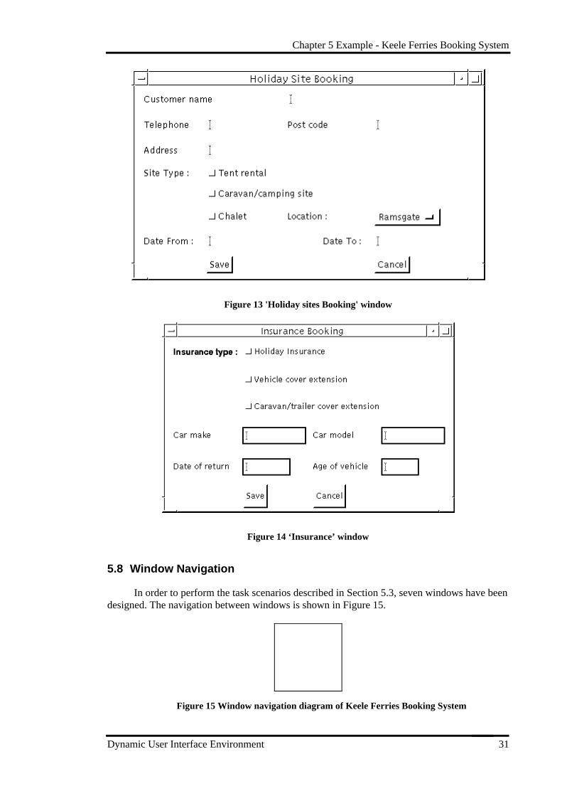
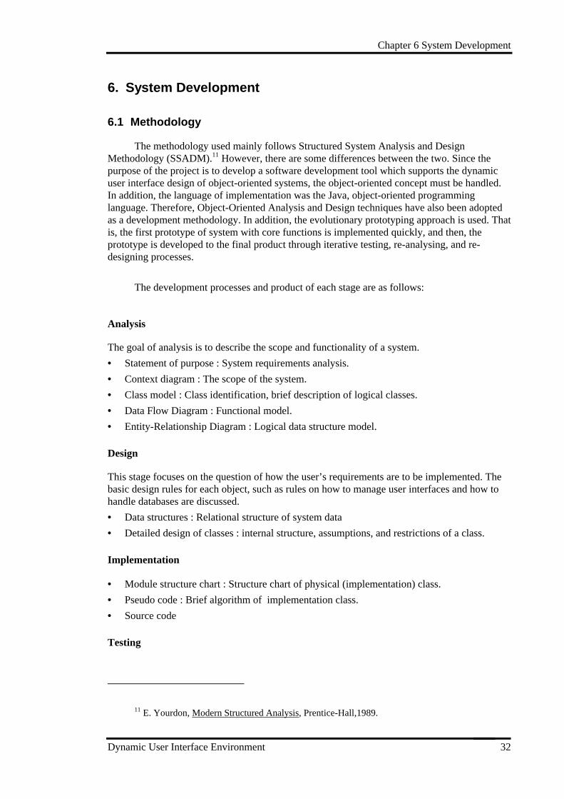
5.7 Window Design & Prototype
The initial windows have been designed on paper by hand. After the evaluation of theinitial design, some changes have been made to the window designs. The last version of papersketches have been prototyped with Java AWT. Two window prototypes are shown in Figure13 and Figure 14.
Chapter 5 Example - Keele Ferries Booking System
Dynamic User Interface Environment 31
Figure 13 'Holiday sites Booking' window
Figure 14 ‘Insurance’ window
5.8 Window Navigation
In order to perform the task scenarios described in Section 5.3, seven windows have beendesigned. The navigation between windows is shown in Figure 15.
Figure 15 Window navigation diagram of Keele Ferries Booking System
Chapter 6 System Development
Dynamic User Interface Environment 32
6. System Development
6.1 Methodology
The methodology used mainly follows Structured System Analysis and DesignMethodology (SSADM).11 However, there are some differences between the two. Since thepurpose of the project is to develop a software development tool which supports the dynamicuser interface design of object-oriented systems, the object-oriented concept must be handled.In addition, the language of implementation was the Java, object-oriented programminglanguage. Therefore, Object-Oriented Analysis and Design techniques have also been adoptedas a development methodology. In addition, the evolutionary prototyping approach is used. Thatis, the first prototype of system with core functions is implemented quickly, and then, theprototype is developed to the final product through iterative testing, re-analysing, and re-designing processes.
The development processes and product of each stage are as follows:
Analysis
The goal of analysis is to describe the scope and functionality of a system.
• Statement of purpose : System requirements analysis.
• Context diagram : The scope of the system.
• Class model : Class identification, brief description of logical classes.
• Data Flow Diagram : Functional model.
• Entity-Relationship Diagram : Logical data structure model.
Design
This stage focuses on the question of how the user’s requirements are to be implemented. Thebasic design rules for each object, such as rules on how to manage user interfaces and how tohandle databases are discussed.
• Data structures : Relational structure of system data
• Detailed design of classes : internal structure, assumptions, and restrictions of a class.
Implementation
• Module structure chart : Structure chart of physical (implementation) class.
• Pseudo code : Brief algorithm of implementation class.
• Source code
Testing
11 E. Yourdon, Modern Structured Analysis, Prentice-Hall,1989.
Chapter 6 System Development
Dynamic User Interface Environment 33
• Testing forms and data
• Testing results
6.2 Analysis
6.2.1 System Requirements
The statement of purpose represents a description of the goals of the system, thefunctions it must perform, and the constraints of the system. The statement of purpose is shownin Appendix A.
6.2.2 Context Diagram
The scope of the system is shown in the context diagram in Appendix B. The outsideentities which interact with the system are a developer and a STD editor. The developer isanyone who working on the GUI system development. The group of developers will bediscussed in more detail in Section 7.2. STD editor is the state transition diagram drawing toolas explained in Section 3.3.
6.2.3 Class Model
The classes identified in the system are :
• project
• user class
• user window
The attributes and behaviours of each class and their relationships will be explained indetail in Chapter 7.
Project
Project means developer’s (tool user’s) project - a system development. For instance, theKeele ferries booking system used as a running example in this dissertation is a project. Aproject has business-specific classes, objects (an instance of a class), window designs, statetransition diagrams for classes, and linking between STD and user windows.
User Class
User classes represent things in the real world that the project system is concerned with.For example, ‘customer’ and ‘ferries service’ are user classes of the Keele ferries bookingsystem. A user class has a state transition diagram, and a number of user objects which areinstances of that user class.
User Window
Chapter 6 System Development
Dynamic User Interface Environment 34
A user window is a static user interface design for a project. For example, Figure 13 onpage 31 is a user window of the Keele Ferries Booking System. A window consists of a numberof components, component events, and component attributes. A user window has eventhandling code which is generated by the tool based on linking data. This should do the intendedwork - window navigation and component content sharing.
6.2.4 Data Flow Diagram
The function flows are shown in Appendix C.
6.2.5 Entity-Relationship Diagram
ERD represents the logical data model of the system as entities and their relationships. Inthe system, the ERD can be classified into three logical parts - STD, user window, and linkingof user window and STD. The ERDs are shown in Appendix D.
6.3 Design
6.3.1 Data Structures
In order to store data files, a relational database will be used. Appendix E shows the datastructures of the system. Some attributes represented as a primary key such as user class name,screen name, etc. should be unique throughout the system.
6.3.2 Detailed Design of Class
Before starting implementation, it is useful to specify a scope, assumptions, restrictions,and a description of the internal structure of each class module.
6.3.2.1 Project
A project is the basic unit of work to be done by the system. When the system starts, auser needs to open a project and then, all information belonging to that project such as STDinformation of classes and user window designs will be retrieved. In order to add dynamics tothe static window designs, windows need to be linked to STDs by the user. This linking can bespecified in four possible cases - link windows to STD actions, link component events to STDconditions, link component attributes to STD actions, and link component attributes to objectattributes.
6.3.2.2 User Class and Class Attributes
The system should allow users to add or update class attributes of a user class. However,the class itself should not be deleted or updated in the system because it is directly related to astate transition diagram of that class, which is outside the scope of the system. For example,assume the ‘ferries service’ class of the Keele ferries booking system has a ‘ferries serviceSTD’ drawn on the STD editor. If the class name is changed to ‘scheduled ferries’, the ferries
Chapter 6 System Development
Dynamic User Interface Environment 35
service STD information will be lost. For that reason, a user class can be updated only in theSTD editor.
6.3.2.2.1 User object and object attributes
Users can add or update an object and object attributes freely. The change of object andobject attributes might cause the deletion of linking data because some component attributescould already be linked to these object attributes.
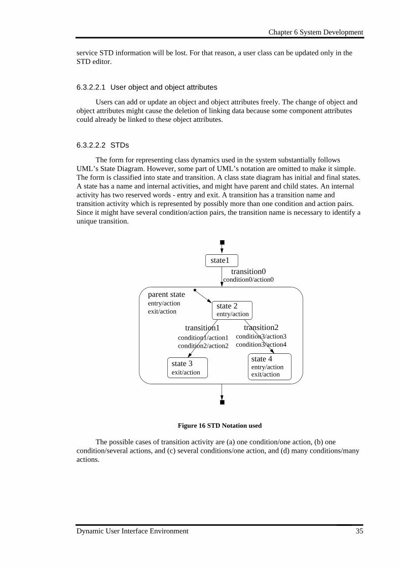
6.3.2.2.2 STDs
The form for representing class dynamics used in the system substantially followsUML’s State Diagram. However, some part of UML’s notation are omitted to make it simple.The form is classified into state and transition. A class state diagram has initial and final states.A state has a name and internal activities, and might have parent and child states. An internalactivity has two reserved words - entry and exit. A transition has a transition name andtransition activity which is represented by possibly more than one condition and action pairs.Since it might have several condition/action pairs, the transition name is necessary to identify aunique transition.
state 2entry/action
state 3exit/action
state 4entry/actionexit/action
parent stateentry/actionexit/action
transition1condition1/action1condition2/action2
state1transition0
condition0/action0
transition2condition3/action3condition3/action4
Figure 16 STD Notation used
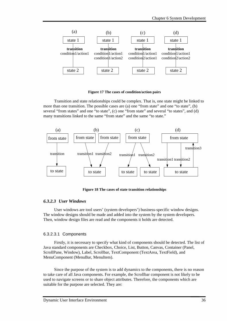
The possible cases of transition activity are (a) one condition/one action, (b) onecondition/several actions, and (c) several conditions/one action, and (d) many conditions/manyactions.
Chapter 6 System Development
Dynamic User Interface Environment 36
state 1
state 2
transitioncondition1/action1
state 1
state 2
transitioncondition1/action1condition1/action2
state 1
state 2
transitioncondition1/action1condition2/action1
(a) (b) (c)
state 1
state 2
transitioncondition1/action1condition2/action2
(d)
Figure 17 The cases of condition/action pairs
Transition and state relationships could be complex. That is, one state might be linked tomore than one transition. The possible cases are (a) one “from state” and one “to state”, (b)several “from states” and one “to state”, (c) one “from state” and several “to states”, and (d)many transitions linked to the same “from state” and the same “to state.”
from state
to state
from state from state
to state to state to state
from state
transition transition1 transition2 transition1 transition2
(a) (b) (c)
from state
to state
(d)
transition1
transition3
transition2
Figure 18 The cases of state transition relationships
6.3.2.3 User Windows
User windows are tool users’ (system developers’) business-specific window designs.The window designs should be made and added into the system by the system developers.Then, window design files are read and the components it holds are detected.
6.3.2.3.1 Components
Firstly, it is necessary to specify what kind of components should be detected. The list ofJava standard components are Checkbox, Choice, List, Button, Canvas, Container (Panel,ScrollPane, Window), Label, Scrollbar, TextComponent (TextArea, TextField), andMenuComponent (MenuBar, MenuItem).
Since the purpose of the system is to add dynamics to the components, there is no reasonto take care of all Java components. For example, the Scrollbar component is not likely to beused to navigate screens or to share object attributes. Therefore, the components which aresuitable for the purpose are selected. They are:
Chapter 6 System Development
Dynamic User Interface Environment 37
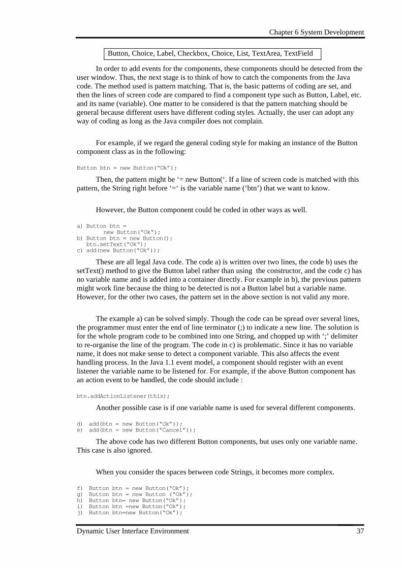
Button, Choice, Label, Checkbox, Choice, List, TextArea, TextField
In order to add events for the components, these components should be detected from theuser window. Thus, the next stage is to think of how to catch the components from the Javacode. The method used is pattern matching. That is, the basic patterns of coding are set, andthen the lines of screen code are compared to find a component type such as Button, Label, etc.and its name (variable). One matter to be considered is that the pattern matching should begeneral because different users have different coding styles. Actually, the user can adopt anyway of coding as long as the Java compiler does not complain.
For example, if we regard the general coding style for making an instance of the Buttoncomponent class as in the following:
Button btn = new Button( “ Ok” );
Then, the pattern might be ‘= new Button(‘. If a line of screen code is matched with thispattern, the String right before ‘=‘ is the variable name (‘btn’) that we want to know.
However, the Button component could be coded in other ways as well.
a) Button btn = new Button( “ Ok“ );b) Button btn = new Button(); btn.setText( “ Ok“ );c) add(new Button( “ Ok” ));
These are all legal Java code. The code a) is written over two lines, the code b) uses thesetText() method to give the Button label rather than using the constructor, and the code c) hasno variable name and is added into a container directly. For example in b), the previous patternmight work fine because the thing to be detected is not a Button label but a variable name.However, for the other two cases, the pattern set in the above section is not valid any more.
The example a) can be solved simply. Though the code can be spread over several lines,the programmer must enter the end of line terminator (;) to indicate a new line. The solution isfor the whole program code to be combined into one String, and chopped up with ‘;’ delimiterto re-organise the line of the program. The code in c) is problematic. Since it has no variablename, it does not make sense to detect a component variable. This also affects the eventhandling process. In the Java 1.1 event model, a component should register with an eventlistener the variable name to be listened for. For example, if the above Button component hasan action event to be handled, the code should include :
btn.addActionListener(this);
Another possible case is if one variable name is used for several different components.
d) add(btn = new Button( “ Ok” ));e) add(btn = new Button( “ Cancel ” ));
The above code has two different Button components, but uses only one variable name.This case is also ignored.
When you consider the spaces between code Strings, it becomes more complex.
f) Button btn = new Button( “ Ok” );g) Button btn = new Button ( “ Ok” );h) Button btn= new Button( “ Ok” );i) Button btn =new Button( “ Ok” );j) Button btn=new Button( “ Ok” );
Chapter 6 System Development
Dynamic User Interface Environment 38
Since the pattern matching method recognises a space as a character, the similar abovecode fragments require different patterns to be detected.
In order to make the pattern matching generic and reliable, which can detect all requiredcomponents from the different style of user programs, all these possible cases need to beconsidered.
6.3.2.3.2 Component Event
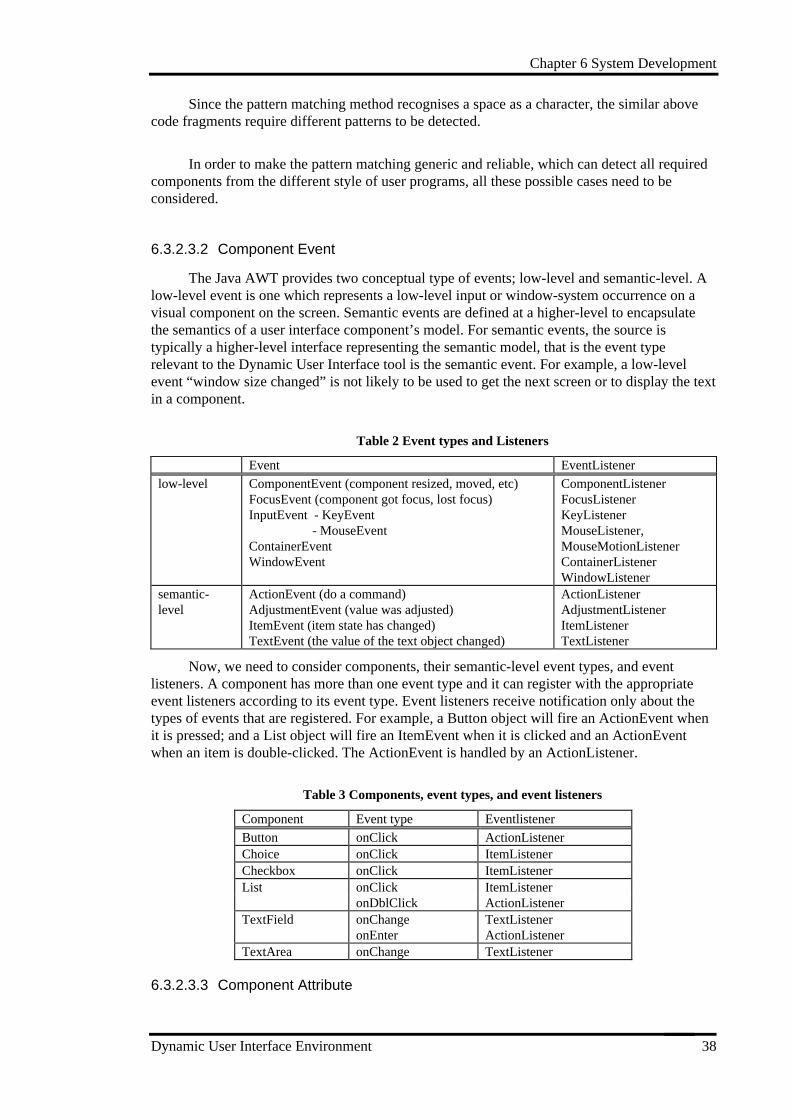
The Java AWT provides two conceptual type of events; low-level and semantic-level. Alow-level event is one which represents a low-level input or window-system occurrence on avisual component on the screen. Semantic events are defined at a higher-level to encapsulatethe semantics of a user interface component’s model. For semantic events, the source istypically a higher-level interface representing the semantic model, that is the event typerelevant to the Dynamic User Interface tool is the semantic event. For example, a low-levelevent “window size changed” is not likely to be used to get the next screen or to display the textin a component.
Table 2 Event types and Listeners
Event EventListener
low-level ComponentEvent (component resized, moved, etc)FocusEvent (component got focus, lost focus)InputEvent - KeyEvent - MouseEventContainerEventWindowEvent
ComponentListenerFocusListenerKeyListenerMouseListener,MouseMotionListenerContainerListenerWindowListener
semantic-level
ActionEvent (do a command)AdjustmentEvent (value was adjusted)ItemEvent (item state has changed)TextEvent (the value of the text object changed)
ActionListenerAdjustmentListenerItemListenerTextListener
Now, we need to consider components, their semantic-level event types, and eventlisteners. A component has more than one event type and it can register with the appropriateevent listeners according to its event type. Event listeners receive notification only about thetypes of events that are registered. For example, a Button object will fire an ActionEvent whenit is pressed; and a List object will fire an ItemEvent when it is clicked and an ActionEventwhen an item is double-clicked. The ActionEvent is handled by an ActionListener.
Table 3 Components, event types, and event listeners
Component Event type Eventlistener
Button onClick ActionListenerChoice onClick ItemListenerCheckbox onClick ItemListenerList onClick ItemListener
onDblClick ActionListenerTextField onChange TextListener
onEnter ActionListenerTextArea onChange TextListener
6.3.2.3.3 Component Attribute
Chapter 6 System Development
Dynamic User Interface Environment 39
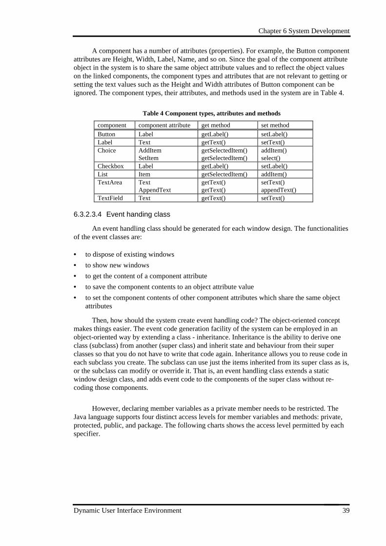
A component has a number of attributes (properties). For example, the Button componentattributes are Height, Width, Label, Name, and so on. Since the goal of the component attributeobject in the system is to share the same object attribute values and to reflect the object valueson the linked components, the component types and attributes that are not relevant to getting orsetting the text values such as the Height and Width attributes of Button component can beignored. The component types, their attributes, and methods used in the system are in Table 4.
Table 4 Component types, attributes and methods
component component attribute get method set method
Button Label getLabel() setLabel()Label Text getText() setText()Choice AddItem getSelectedItem() addItem()
SetItem getSelectedItem() select()Checkbox Label getLabel() setLabel()List Item getSelectedItem() addItem()TextArea Text getText() setText()
AppendText getText() appendText()TextField Text getText() setText()
6.3.2.3.4 Event handing class
An event handling class should be generated for each window design. The functionalitiesof the event classes are:
• to dispose of existing windows
• to show new windows
• to get the content of a component attribute
• to save the component contents to an object attribute value
• to set the component contents of other component attributes which share the same objectattributes
Then, how should the system create event handling code? The object-oriented conceptmakes things easier. The event code generation facility of the system can be employed in anobject-oriented way by extending a class - inheritance. Inheritance is the ability to derive oneclass (subclass) from another (super class) and inherit state and behaviour from their superclasses so that you do not have to write that code again. Inheritance allows you to reuse code ineach subclass you create. The subclass can use just the items inherited from its super class as is,or the subclass can modify or override it. That is, an event handling class extends a staticwindow design class, and adds event code to the components of the super class without re-coding those components.
However, declaring member variables as a private member needs to be restricted. TheJava language supports four distinct access levels for member variables and methods: private,protected, public, and package. The following charts shows the access level permitted by eachspecifier.
Chapter 6 System Development
Dynamic User Interface Environment 40
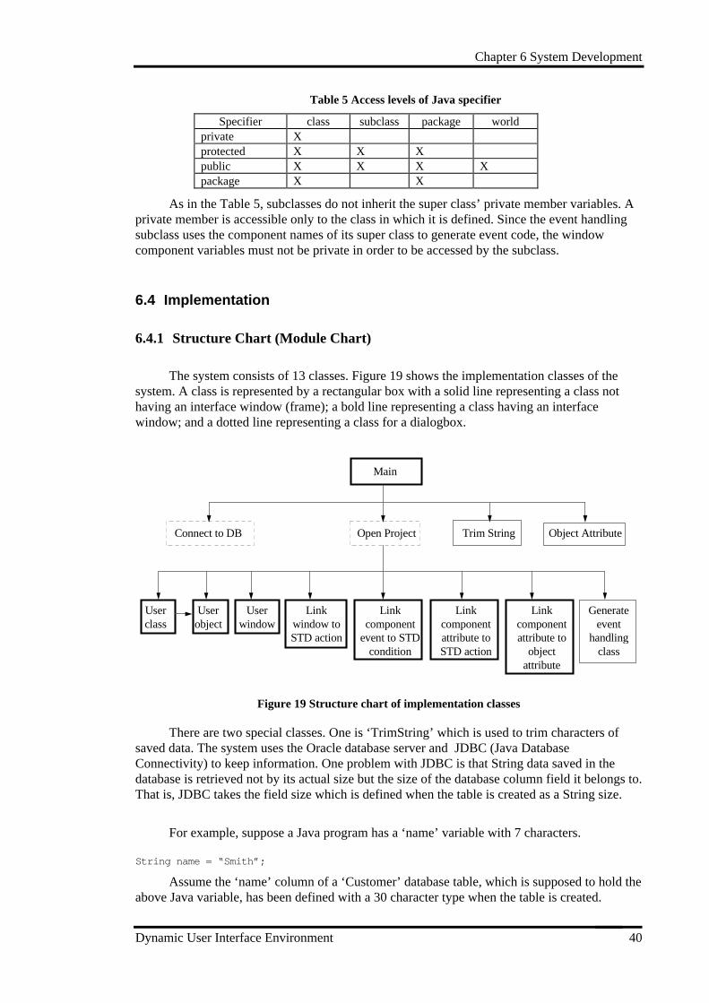
Table 5 Access levels of Java specifier
Specifier class subclass package worldprivate Xprotected X X Xpublic X X X Xpackage X X
As in the Table 5, subclasses do not inherit the super class’ private member variables. Aprivate member is accessible only to the class in which it is defined. Since the event handlingsubclass uses the component names of its super class to generate event code, the windowcomponent variables must not be private in order to be accessed by the subclass.
6.4 Implementation
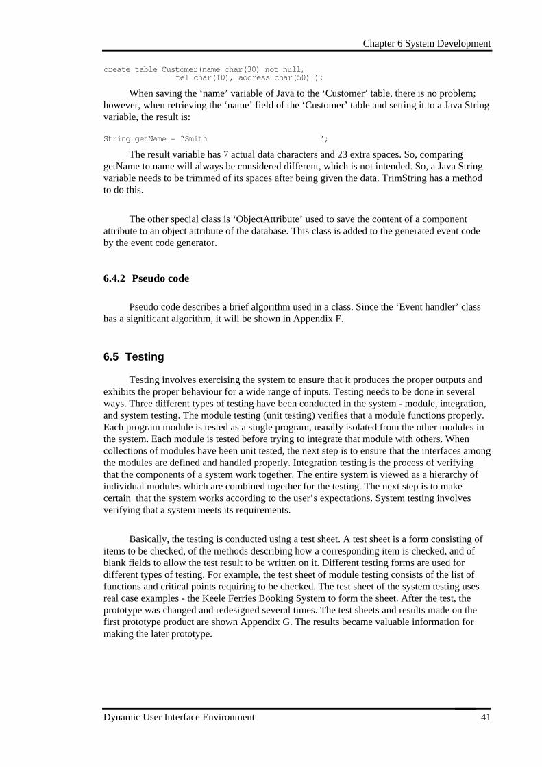
6.4.1 Structure Chart (Module Chart)
The system consists of 13 classes. Figure 19 shows the implementation classes of thesystem. A class is represented by a rectangular box with a solid line representing a class nothaving an interface window (frame); a bold line representing a class having an interfacewindow; and a dotted line representing a class for a dialogbox.
Main
Open ProjectConnect to DB Trim String
Userclass
Userobject
Userwindow
Linkwindow toSTD action
Linkcomponent
event to STDcondition
Linkcomponentattribute toSTD action
Linkcomponentattribute to
objectattribute
Generateevent
handlingclass
Object Attribute
Figure 19 Structure chart of implementation classes
There are two special classes. One is ‘TrimString’ which is used to trim characters ofsaved data. The system uses the Oracle database server and JDBC (Java DatabaseConnectivity) to keep information. One problem with JDBC is that String data saved in thedatabase is retrieved not by its actual size but the size of the database column field it belongs to.That is, JDBC takes the field size which is defined when the table is created as a String size.
For example, suppose a Java program has a ‘name’ variable with 7 characters.
String name = “ Smith ” ;
Assume the ‘name’ column of a ‘Customer’ database table, which is supposed to hold theabove Java variable, has been defined with a 30 character type when the table is created.
Chapter 6 System Development
Dynamic User Interface Environment 41
create table Customer(name char(30) not null,tel char(10), address char(50) );
When saving the ‘name’ variable of Java to the ‘Customer’ table, there is no problem;however, when retrieving the ‘name’ field of the ‘Customer’ table and setting it to a Java Stringvariable, the result is:
String getName = “ Smith “ ;
The result variable has 7 actual data characters and 23 extra spaces. So, comparinggetName to name will always be considered different, which is not intended. So, a Java Stringvariable needs to be trimmed of its spaces after being given the data. TrimString has a methodto do this.
The other special class is ‘ObjectAttribute’ used to save the content of a componentattribute to an object attribute of the database. This class is added to the generated event codeby the event code generator.
6.4.2 Pseudo code
Pseudo code describes a brief algorithm used in a class. Since the ‘Event handler’ classhas a significant algorithm, it will be shown in Appendix F.
6.5 Testing
Testing involves exercising the system to ensure that it produces the proper outputs andexhibits the proper behaviour for a wide range of inputs. Testing needs to be done in severalways. Three different types of testing have been conducted in the system - module, integration,and system testing. The module testing (unit testing) verifies that a module functions properly.Each program module is tested as a single program, usually isolated from the other modules inthe system. Each module is tested before trying to integrate that module with others. Whencollections of modules have been unit tested, the next step is to ensure that the interfaces amongthe modules are defined and handled properly. Integration testing is the process of verifyingthat the components of a system work together. The entire system is viewed as a hierarchy ofindividual modules which are combined together for the testing. The next step is to makecertain that the system works according to the user’s expectations. System testing involvesverifying that a system meets its requirements.
Basically, the testing is conducted using a test sheet. A test sheet is a form consisting ofitems to be checked, of the methods describing how a corresponding item is checked, and ofblank fields to allow the test result to be written on it. Different testing forms are used fordifferent types of testing. For example, the test sheet of module testing consists of the list offunctions and critical points requiring to be checked. The test sheet of the system testing usesreal case examples - the Keele Ferries Booking System to form the sheet. After the test, theprototype was changed and redesigned several times. The test sheets and results made on thefirst prototype product are shown Appendix G. The results became valuable information formaking the later prototype.
Chapter 6 System Development
Dynamic User Interface Environment 42
6.6 Developing the First Prototype to the Final Product
Applying the evolutionary prototyping approach leads to an iterative, and cyclicaldevelopment process. The goal of the first prototype is to obtain an initial conception of theproposed system and to develop a prototype that makes it possible to test these conceptions onthe basis of realistic examples. The result of the first prototype serves as a base system for thesucceeding iterative process of later prototype development. Prototypes are successivelyelaborated toward the final product by solving problems exposed, by adding redefined or newfunctions, and by making it more complete and usable.
After completing the testing of first prototype, the following have been added to thesecond prototype (the final product).
Solve the problems of the first prototype exposed by the testing
• Null values: Some data must have values. The program has been changed so that nullvalues are prevented.
• Redundant data: There is no restriction to entering the same data several times. A modulewhich removes redundancy has been implemented.
• Update information: After the change of either user classes or user window designs, alllinking data related to them must be deleted.
Complete functions
• Complete functions: Since the purpose of the first prototype is to make a prototype systemquickly, some of the functions which are not urgent were skipped. For example, in the‘EventHandler’ class of the first prototype, the event handling code for only the‘ActionListener’ was implemented. Since all other listeners basically have the samealgorithm, it could be delayed.
Add new functions
• File menu: Users can see a file in the text area, edit and save it.
• View menu: After linking information, it is impossible to memorise all the linked data. Thisfunction allows users to view and to delete the linked data.
• Compile and run: Users can compile and run the Java file.
• View screen : User can see the designed user windows inside the system.
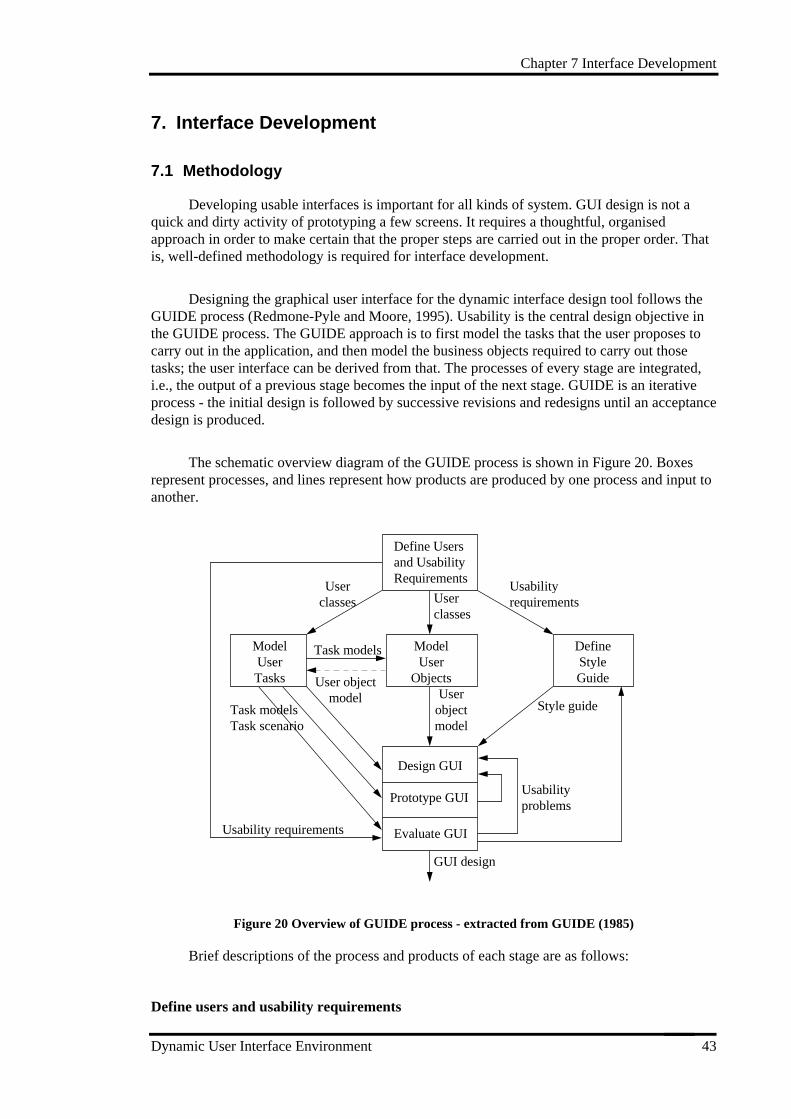
Chapter 7 Interface Development
Dynamic User Interface Environment 43
7. Interface Development
7.1 Methodology
Developing usable interfaces is important for all kinds of system. GUI design is not aquick and dirty activity of prototyping a few screens. It requires a thoughtful, organisedapproach in order to make certain that the proper steps are carried out in the proper order. Thatis, well-defined methodology is required for interface development.
Designing the graphical user interface for the dynamic interface design tool follows theGUIDE process (Redmone-Pyle and Moore, 1995). Usability is the central design objective inthe GUIDE process. The GUIDE approach is to first model the tasks that the user proposes tocarry out in the application, and then model the business objects required to carry out thosetasks; the user interface can be derived from that. The processes of every stage are integrated,i.e., the output of a previous stage becomes the input of the next stage. GUIDE is an iterativeprocess - the initial design is followed by successive revisions and redesigns until an acceptancedesign is produced.
The schematic overview diagram of the GUIDE process is shown in Figure 20. Boxesrepresent processes, and lines represent how products are produced by one process and input toanother.
Define Usersand UsabilityRequirements
ModelUserTasks
ModelUser
Objects
DefineStyleGuide
Design GUI
Prototype GUI
Evaluate GUI
GUI design
Userclasses
Userclasses
Usabilityrequirements
Task models
User objectmodel User
objectmodel
Style guide
Usabilityproblems
Task modelsTask scenario
Usability requirements
Figure 20 Overview of GUIDE process - extracted from GUIDE (1985)
Brief descriptions of the process and products of each stage are as follows:
Define users and usability requirements
Chapter 7 Interface Development
Dynamic User Interface Environment 44
The process of identifying the end-users and their special characteristics; specifying theirusability requirements. The products are
• user class descriptions : describing the different types of end-user
• usability requirements : each with one or more evaluation criteria and the level which theGUI must achieve to be acceptable.
Model user tasks
The aim of this process is analysis and modelling of user tasks. The products are
• task models : what tasks a user will perform, hierarchical task analysis showing the generichierarchical structure of each task
• task scenarios : example of individual instances of the task, which are suitable forprototyping.
Model user objects
The aim is identifying the objects and object relationships in the system, and actions thatpeople perform on these objects. Important work to be done at this stage is dynamic modelling.If the objects has significant dynamic behaviour, the dynamic behaviour of the objects in thesystem should be modelled. The products are
• one or more user object model
• a glossary of user terms
• Statechart : dynamic model diagram
Define style guide
The aim is for the GUI to have a consistent style. The product is
• an application style guide defining GUI standards to be used for the system.
Design GUI
The aim is to design an initial GUI which supports user tasks and present the user’sobjects clearly. The products are
• window design, including specification of interactive behaviour
• window navigation design : the relationship between windows, shows how users can movefrom one window to another
Prototype GUI
The aim is to investigate the usability (and feasibility) of the proposed GUI design andthe validity of the task model, user object model and style guide. The products are
• a working prototype GUI
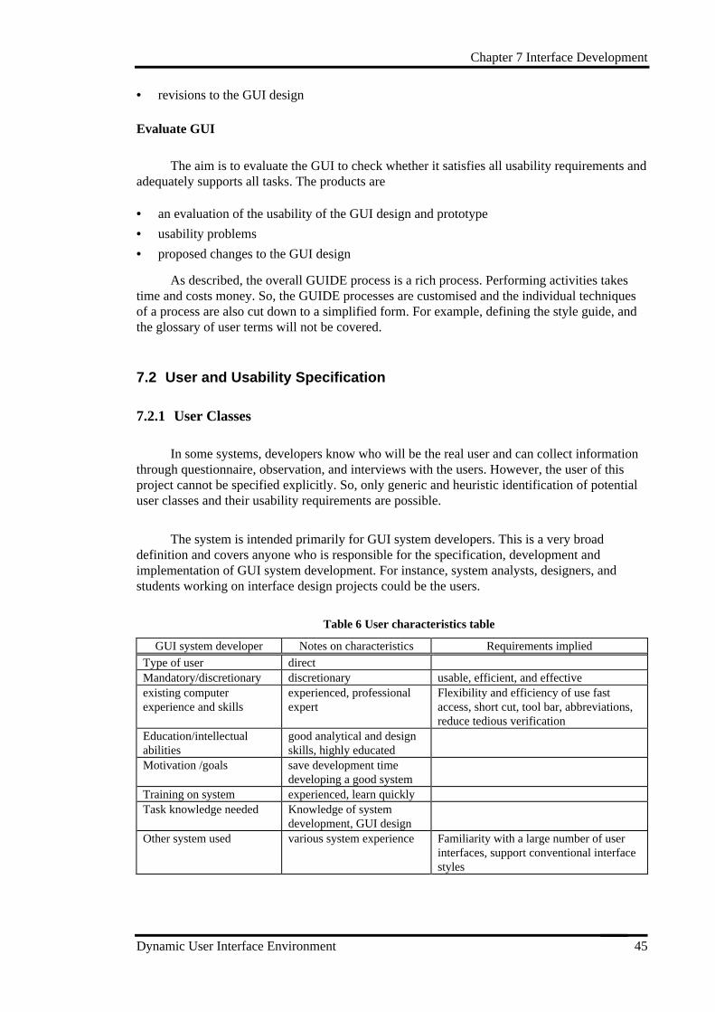
Chapter 7 Interface Development
Dynamic User Interface Environment 45
• revisions to the GUI design
Evaluate GUI
The aim is to evaluate the GUI to check whether it satisfies all usability requirements andadequately supports all tasks. The products are
• an evaluation of the usability of the GUI design and prototype
• usability problems
• proposed changes to the GUI design
As described, the overall GUIDE process is a rich process. Performing activities takestime and costs money. So, the GUIDE processes are customised and the individual techniquesof a process are also cut down to a simplified form. For example, defining the style guide, andthe glossary of user terms will not be covered.
7.2 User and Usability Specification
7.2.1 User Classes
In some systems, developers know who will be the real user and can collect informationthrough questionnaire, observation, and interviews with the users. However, the user of thisproject cannot be specified explicitly. So, only generic and heuristic identification of potentialuser classes and their usability requirements are possible.
The system is intended primarily for GUI system developers. This is a very broaddefinition and covers anyone who is responsible for the specification, development andimplementation of GUI system development. For instance, system analysts, designers, andstudents working on interface design projects could be the users.
Table 6 User characteristics table
GUI system developer Notes on characteristics Requirements implied
Type of user directMandatory/discretionary discretionary usable, efficient, and effectiveexisting computerexperience and skills
experienced, professionalexpert
Flexibility and efficiency of use fastaccess, short cut, tool bar, abbreviations,reduce tedious verification
Education/intellectualabilities
good analytical and designskills, highly educated
Motivation /goals save development timedeveloping a good system
Training on system experienced, learn quicklyTask knowledge needed Knowledge of system
development, GUI designOther system used various system experience Familiarity with a large number of user
interfaces, support conventional interfacestyles
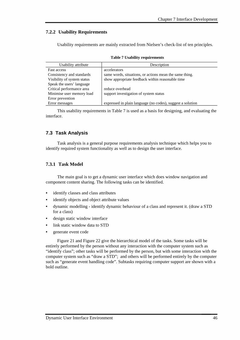
Chapter 7 Interface Development
Dynamic User Interface Environment 46
7.2.2 Usability Requirements
Usability requirements are mainly extracted from Nielsen’s check-list of ten principles.
Table 7 Usability requirements
Usability attribute DescriptionFast access acceleratorsConsistency and standards same words, situations, or actions mean the same thing.Visibility of system status show appropriate feedback within reasonable timeSpeak the users’ languageCritical performance area reduce overheadMinimise user memory load support investigation of system statusError preventionError messages expressed in plain language (no codes), suggest a solution
This usability requirements in Table 7 is used as a basis for designing, and evaluating theinterface.
7.3 Task Analysis
Task analysis is a general purpose requirements analysis technique which helps you toidentify required system functionality as well as to design the user interface.
7.3.1 Task Model
The main goal is to get a dynamic user interface which does window navigation andcomponent content sharing. The following tasks can be identified.
• identify classes and class attributes
• identify objects and object attribute values
• dynamic modelling - identify dynamic behaviour of a class and represent it. (draw a STDfor a class)
• design static window interface
• link static window data to STD
• generate event code
Figure 21 and Figure 22 give the hierarchical model of the tasks. Some tasks will beentirely performed by the person without any interaction with the computer system such as“identify class”; other tasks will be performed by the person, but with some interaction with thecomputer system such as “draw a STD”; and others will be performed entirely by the computersuch as “generate event handling code”. Subtasks requiring computer support are shown with abold outline.
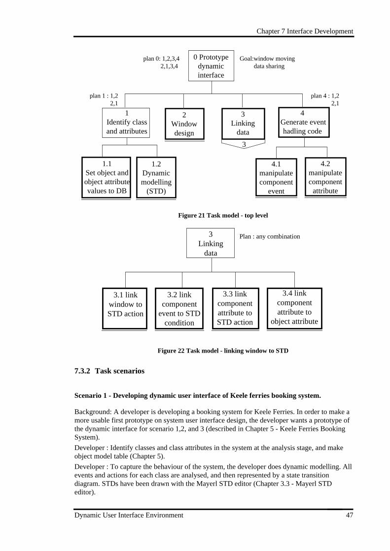
Chapter 7 Interface Development
Dynamic User Interface Environment 47
0 Prototypedynamicinterface
1Identify classand attributes
1.2Dynamicmodelling
(STD)
2Windowdesign
4 Generate event
hadling code
1.1Set object andobject attributevalues to DB
4.1manipulatecomponent
event
4.2manipulatecomponentattribute
Goal:window moving data sharing
plan 0: 1,2,3,4 2,1,3,4
plan 4 : 1,2 2,1
3Linking
data
3
plan 1 : 1,2 2,1
Figure 21 Task model - top level
3Linking
data
3.1 linkwindow toSTD action
3.2 linkcomponent
event to STDcondition
3.3 linkcomponentattribute toSTD action
3.4 linkcomponentattribute to
object attribute
Plan : any combination
Figure 22 Task model - linking window to STD
7.3.2 Task scenarios
Scenario 1 - Developing dynamic user interface of Keele ferries booking system.
Background: A developer is developing a booking system for Keele Ferries. In order to make amore usable first prototype on system user interface design, the developer wants a prototype ofthe dynamic interface for scenario 1,2, and 3 (described in Chapter 5 - Keele Ferries BookingSystem).
Developer : Identify classes and class attributes in the system at the analysis stage, and makeobject model table (Chapter 5).
Developer : To capture the behaviour of the system, the developer does dynamic modelling. Allevents and actions for each class are analysed, and then represented by a state transitiondiagram. STDs have been drawn with the Mayerl STD editor (Chapter 3.3 - Mayerl STDeditor).
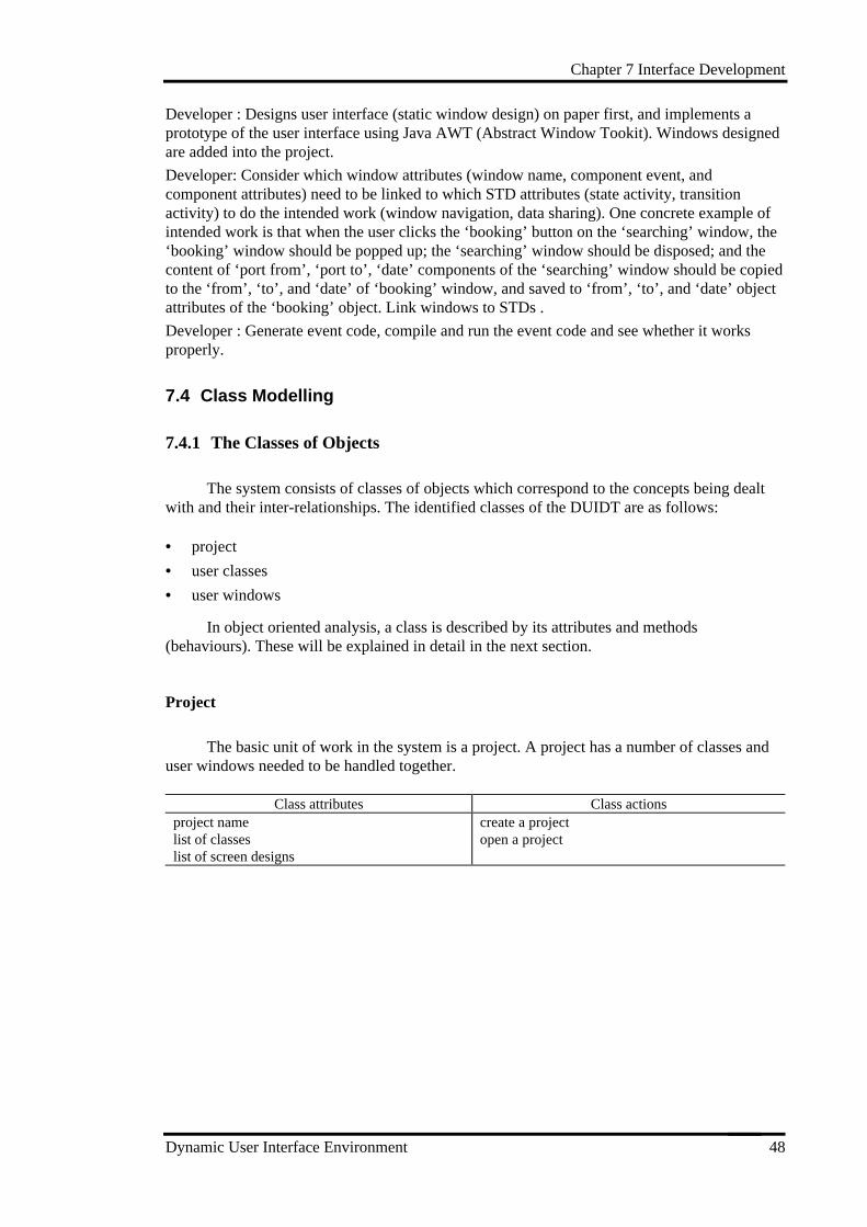
Chapter 7 Interface Development
Dynamic User Interface Environment 48
Developer : Designs user interface (static window design) on paper first, and implements aprototype of the user interface using Java AWT (Abstract Window Tookit). Windows designedare added into the project.
Developer: Consider which window attributes (window name, component event, andcomponent attributes) need to be linked to which STD attributes (state activity, transitionactivity) to do the intended work (window navigation, data sharing). One concrete example ofintended work is that when the user clicks the ‘booking’ button on the ‘searching’ window, the‘booking’ window should be popped up; the ‘searching’ window should be disposed; and thecontent of ‘port from’, ‘port to’, ‘date’ components of the ‘searching’ window should be copiedto the ‘from’, ‘to’, and ‘date’ of ‘booking’ window, and saved to ‘from’, ‘to’, and ‘date’ objectattributes of the ‘booking’ object. Link windows to STDs .
Developer : Generate event code, compile and run the event code and see whether it worksproperly.
7.4 Class Modelling
7.4.1 The Classes of Objects
The system consists of classes of objects which correspond to the concepts being dealtwith and their inter-relationships. The identified classes of the DUIDT are as follows:
• project
• user classes
• user windows
In object oriented analysis, a class is described by its attributes and methods(behaviours). These will be explained in detail in the next section.
Project
The basic unit of work in the system is a project. A project has a number of classes anduser windows needed to be handled together.
Class attributes Class actionsproject namelist of classeslist of screen designs
create a projectopen a project
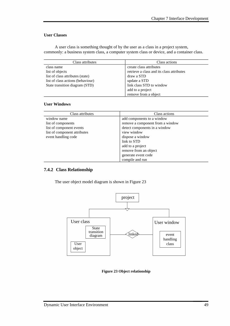
Chapter 7 Interface Development
Dynamic User Interface Environment 49
User Classes
A user class is something thought of by the user as a class in a project system,commonly: a business system class, a computer system class or device, and a container class.
Class attributes Class actionsclass namelist of objectslist of class attributes (state)list of class actions (behaviour)State transition diagram (STD)
create class attributesretrieve a class and its class attributesdraw a STDupdate a STDlink class STD to windowadd to a projectremove from a object
User Windows
Class attributes Class actionswindow namelist of componentslist of component eventslist of component attributesevent handling code
add components to a windowremove a component from a windowdetect components in a windowview windowdispose a windowlink to STDadd to a projectremove from an objectgenerate event codecompile and run
7.4.2 Class Relationship
The user object model diagram is shown in Figure 23
Statetransitiondiagram
User class User window
Userobject
project
linked eventhandling
class
Figure 23 Object relationship
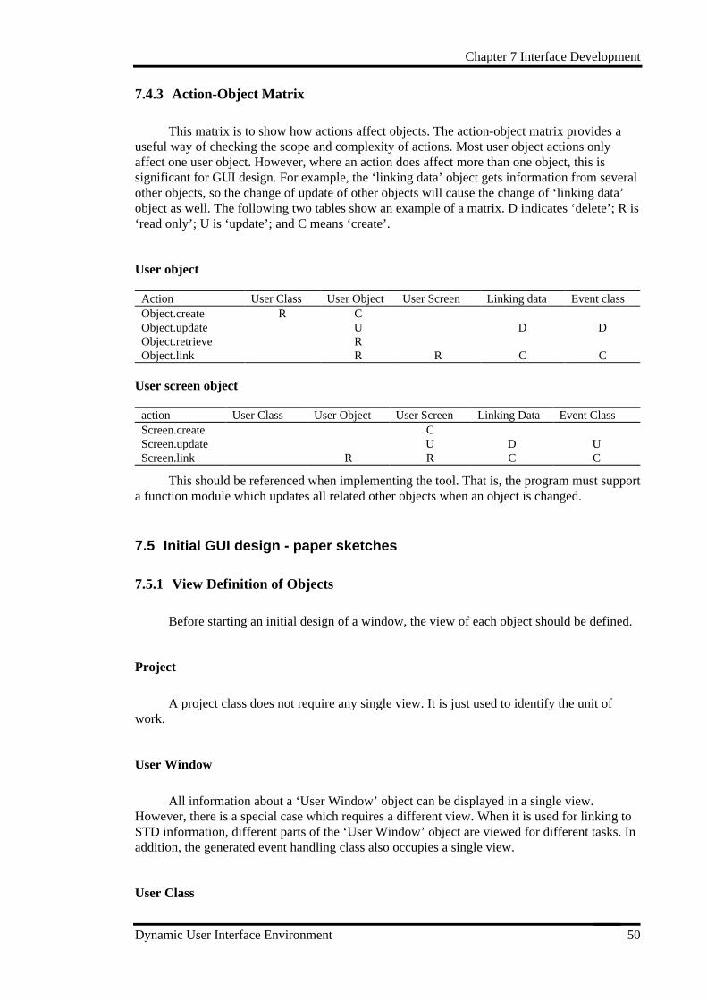
Chapter 7 Interface Development
Dynamic User Interface Environment 50
7.4.3 Action-Object Matrix
This matrix is to show how actions affect objects. The action-object matrix provides auseful way of checking the scope and complexity of actions. Most user object actions onlyaffect one user object. However, where an action does affect more than one object, this issignificant for GUI design. For example, the ‘linking data’ object gets information from severalother objects, so the change of update of other objects will cause the change of ‘linking data’object as well. The following two tables show an example of a matrix. D indicates ‘delete’; R is‘read only’; U is ‘update’; and C means ‘create’.
User object
Action User Class User Object User Screen Linking data Event classObject.create R CObject.update U D DObject.retrieve RObject.link R R C C
User screen object
action User Class User Object User Screen Linking Data Event ClassScreen.create CScreen.update U D UScreen.link R R C C
This should be referenced when implementing the tool. That is, the program must supporta function module which updates all related other objects when an object is changed.
7.5 Initial GUI design - paper sketches
7.5.1 View Definition of Objects
Before starting an initial design of a window, the view of each object should be defined.
Project
A project class does not require any single view. It is just used to identify the unit ofwork.
User Window
All information about a ‘User Window’ object can be displayed in a single view.However, there is a special case which requires a different view. When it is used for linking toSTD information, different parts of the ‘User Window’ object are viewed for different tasks. Inaddition, the generated event handling class also occupies a single view.
User Class
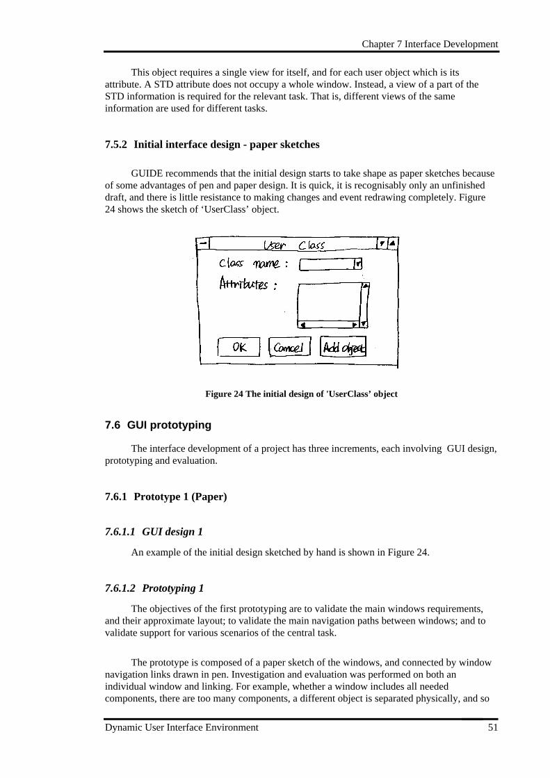
Chapter 7 Interface Development
Dynamic User Interface Environment 51
This object requires a single view for itself, and for each user object which is itsattribute. A STD attribute does not occupy a whole window. Instead, a view of a part of theSTD information is required for the relevant task. That is, different views of the sameinformation are used for different tasks.
7.5.2 Initial interface design - paper sketches
GUIDE recommends that the initial design starts to take shape as paper sketches becauseof some advantages of pen and paper design. It is quick, it is recognisably only an unfinisheddraft, and there is little resistance to making changes and event redrawing completely. Figure24 shows the sketch of ‘UserClass’ object.
Figure 24 The initial design of 'UserClass’ object
7.6 GUI prototyping
The interface development of a project has three increments, each involving GUI design,prototyping and evaluation.
7.6.1 Prototype 1 (Paper)
7.6.1.1 GUI design 1
An example of the initial design sketched by hand is shown in Figure 24.
7.6.1.2 Prototyping 1
The objectives of the first prototyping are to validate the main windows requirements,and their approximate layout; to validate the main navigation paths between windows; and tovalidate support for various scenarios of the central task.
The prototype is composed of a paper sketch of the windows, and connected by windownavigation links drawn in pen. Investigation and evaluation was performed on both anindividual window and linking. For example, whether a window includes all neededcomponents, there are too many components, a different object is separated physically, and so
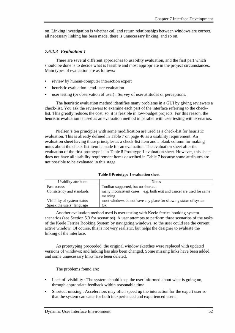
Chapter 7 Interface Development
Dynamic User Interface Environment 52
on. Linking investigation is whether call and return relationships between windows are correct,all necessary linking has been made, there is unnecessary linking, and so on.
7.6.1.3 Evaluation 1
There are several different approaches to usability evaluation, and the first part whichshould be done is to decide what is feasible and most appropriate in the project circumstances.Main types of evaluation are as follows:
• review by human-computer interaction expert
• heuristic evaluation : end-user evaluation
• user testing (or observation of user) : Survey of user attitudes or perceptions.
The heuristic evaluation method identifies many problems in a GUI by giving reviewers acheck-list. You ask the reviewers to examine each part of the interface referring to the check-list. This greatly reduces the cost, so, it is feasible in low-budget projects. For this reason, theheuristic evaluation is used as an evaluation method in parallel with user testing with scenarios.
Nielsen’s ten principles with some modification are used as a check-list for heuristicevaluation. This is already defined in Table 7 on page 46 as a usability requirement. Anevaluation sheet having these principles as a check-list item and a blank column for makingnotes about the check-list item is made for an evaluation. The evaluation sheet after theevaluation of the first prototype is in Table 8 Prototype 1 evaluation sheet. However, this sheetdoes not have all usability requirement items described in Table 7 because some attributes arenot possible to be evaluated in this stage.
Table 8 Prototype 1 evaluation sheet
Usability attribute NotesFast access Toolbar supported, but no shortcutConsistency and standards many inconsistent cases e.g. both exit and cancel are used for same
meaning.Visibility of system status most windows do not have any place for showing status of systemSpeak the users’ language Ok
Another evaluation method used is user testing with Keele ferries booking systemscenarios (see Section 5.3 for scenarios). A user attempts to perform three scenarios of the tasksof the Keele Ferries Booking System by navigating windows, so the user could see the currentactive window. Of course, this is not very realistic, but helps the designer to evaluate thelinking of the interface.
As prototyping proceeded, the original window sketches were replaced with updatedversions of windows; and linking has also been changed. Some missing links have been addedand some unnecessary links have been deleted.
The problems found are:
• Lack of visibility : The system should keep the user informed about what is going on,through appropriate feedback within reasonable time.
• Shortcut missing : Accelerators may often speed up the interaction for the expert user sothat the system can cater for both inexperienced and experienced users.
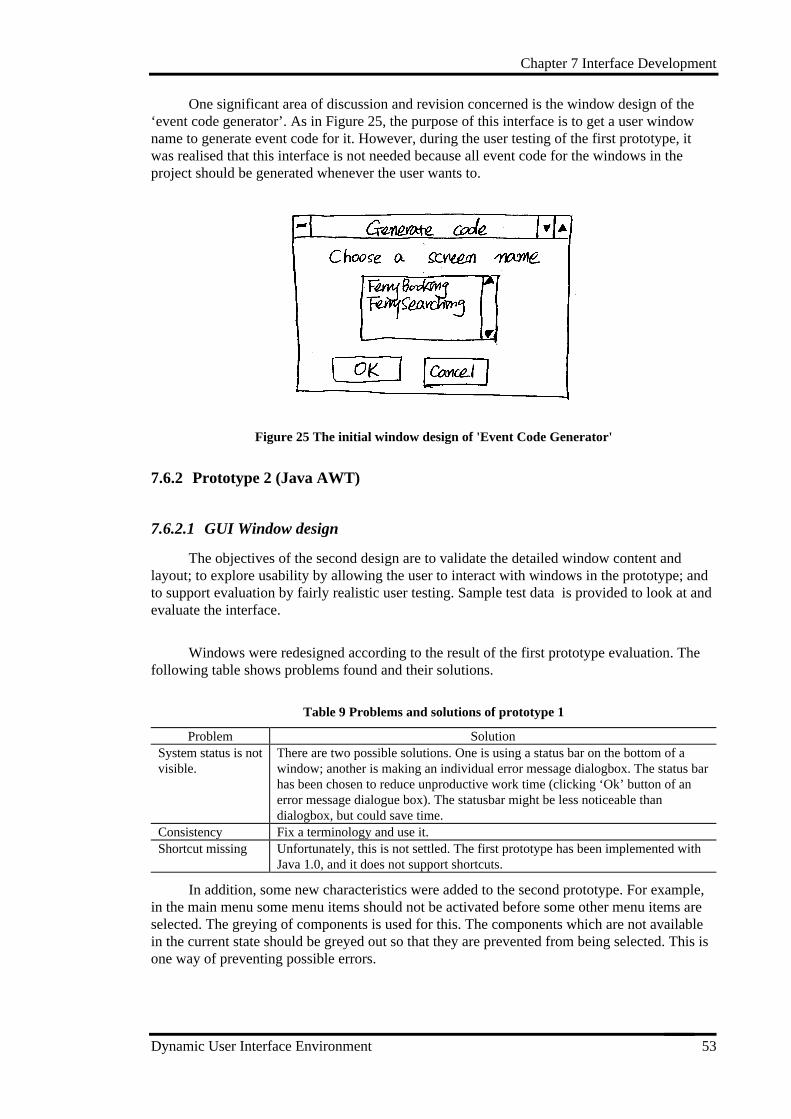
Chapter 7 Interface Development
Dynamic User Interface Environment 53
One significant area of discussion and revision concerned is the window design of the‘event code generator’. As in Figure 25, the purpose of this interface is to get a user windowname to generate event code for it. However, during the user testing of the first prototype, itwas realised that this interface is not needed because all event code for the windows in theproject should be generated whenever the user wants to.
Figure 25 The initial window design of 'Event Code Generator'
7.6.2 Prototype 2 (Java AWT)
7.6.2.1 GUI Window design
The objectives of the second design are to validate the detailed window content andlayout; to explore usability by allowing the user to interact with windows in the prototype; andto support evaluation by fairly realistic user testing. Sample test data is provided to look at andevaluate the interface.
Windows were redesigned according to the result of the first prototype evaluation. Thefollowing table shows problems found and their solutions.
Table 9 Problems and solutions of prototype 1
Problem SolutionSystem status is notvisible.
There are two possible solutions. One is using a status bar on the bottom of awindow; another is making an individual error message dialogbox. The status barhas been chosen to reduce unproductive work time (clicking ‘Ok’ button of anerror message dialogue box). The statusbar might be less noticeable thandialogbox, but could save time.
Consistency Fix a terminology and use it.Shortcut missing Unfortunately, this is not settled. The first prototype has been implemented with
Java 1.0, and it does not support shortcuts.
In addition, some new characteristics were added to the second prototype. For example,in the main menu some menu items should not be activated before some other menu items areselected. The greying of components is used for this. The components which are not availablein the current state should be greyed out so that they are prevented from being selected. This isone way of preventing possible errors.
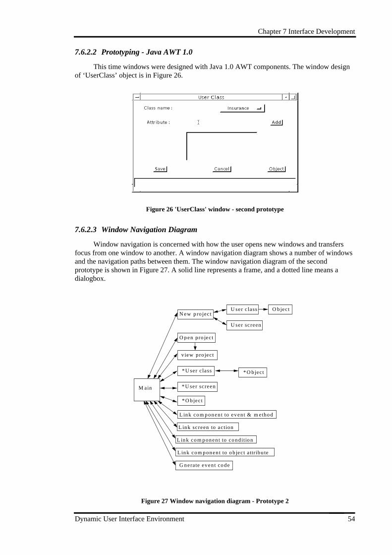
Chapter 7 Interface Development
Dynamic User Interface Environment 54
7.6.2.2 Prototyping - Java AWT 1.0
This time windows were designed with Java 1.0 AWT components. The window designof ‘UserClass’ object is in Figure 26.
Figure 26 'UserClass' window - second prototype
7.6.2.3 Window Navigation Diagram
Window navigation is concerned with how the user opens new windows and transfersfocus from one window to another. A window navigation diagram shows a number of windowsand the navigation paths between them. The window navigation diagram of the secondprototype is shown in Figure 27. A solid line represents a frame, and a dotted line means adialogbox.
M ain
N ew projectU ser cl ass
U ser screen
Object
v iew project
Open project
* U ser class
* U ser screen
* Object
* Object
L ink component to event & m ethod
L ink screen to action
L ink component to condi tion
L ink component to object attr ibute
Gnerate event code
Figure 27 Window navigation diagram - Prototype 2
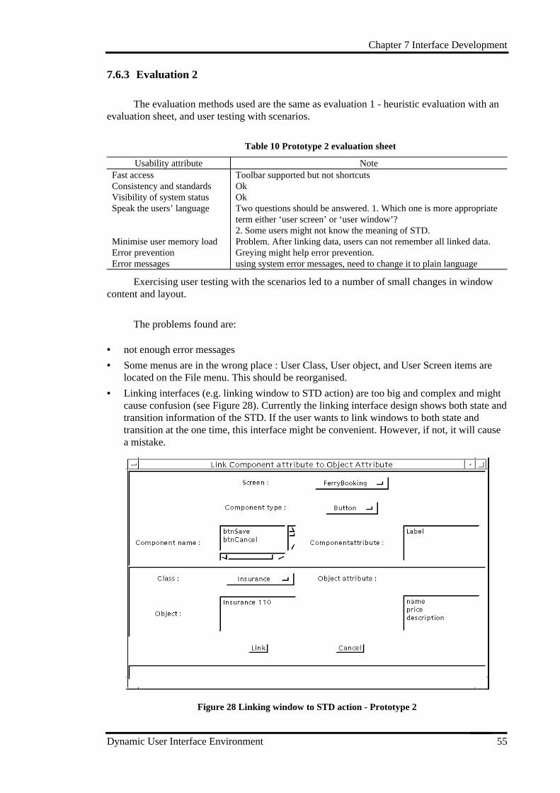
Chapter 7 Interface Development
Dynamic User Interface Environment 55
7.6.3 Evaluation 2
The evaluation methods used are the same as evaluation 1 - heuristic evaluation with anevaluation sheet, and user testing with scenarios.
Table 10 Prototype 2 evaluation sheet
Usability attribute NoteFast access Toolbar supported but not shortcutsConsistency and standards OkVisibility of system status OkSpeak the users’ language Two questions should be answered. 1. Which one is more appropriate
term either ‘user screen’ or ‘user window’?2. Some users might not know the meaning of STD.
Minimise user memory load Problem. After linking data, users can not remember all linked data.Error prevention Greying might help error prevention.Error messages using system error messages, need to change it to plain language
Exercising user testing with the scenarios led to a number of small changes in windowcontent and layout.
The problems found are:
• not enough error messages
• Some menus are in the wrong place : User Class, User object, and User Screen items arelocated on the File menu. This should be reorganised.
• Linking interfaces (e.g. linking window to STD action) are too big and complex and mightcause confusion (see Figure 28). Currently the linking interface design shows both state andtransition information of the STD. If the user wants to link windows to both state andtransition at the one time, this interface might be convenient. However, if not, it will causea mistake.
Figure 28 Linking window to STD action - Prototype 2
Chapter 7 Interface Development
Dynamic User Interface Environment 56
7.6.4 Final product
7.6.4.1 GUI design - Java 1.1
The objectives of this design stage are to confirm that modifications have successfullyresolved usability problems identified in earlier prototypes; and to support informal exercisingof all task scenarios.
The problems provoked in the second prototype evaluation are considered and redesignsolutions have been made.
Table 11 Problems & solutions of Prototype 2
Problem Solutionno way of investigatingdata in the system
add ‘View’ functions showing the linked data in the system
poor design of ‘linkingdata’ interface
Show only one set of information (either state or transition) at one itemand allow the user to swap them.After data linked, all selections which have been made are deselected sothat unintended links are prevented from being saved by mistake
shortcuts missing Though adding shortcuts was suggested in the first prototype evaluation, itwas not implemented because of the limitation of implementationlanguage. Fortunately, Java 1.1 supports shortcuts so they were added tothe system.
7.6.4.2 Windows
The user interface of the final product are as follows.
Figure 29 is the main screen of DUIDT. All functions are shown on the main menu and atool bar is also supported. User can open and edit files in the text area of the screen.
Chapter 7 Interface Development
Dynamic User Interface Environment 57
Figure 29 DUIDT main window
Figure 30 is the interface of ‘window design’ object. Users can add (or remove) awindow design into (or from) the list of project. The users can also view the appearance ofwindow design.
Figure 30 ‘User Window’ interface
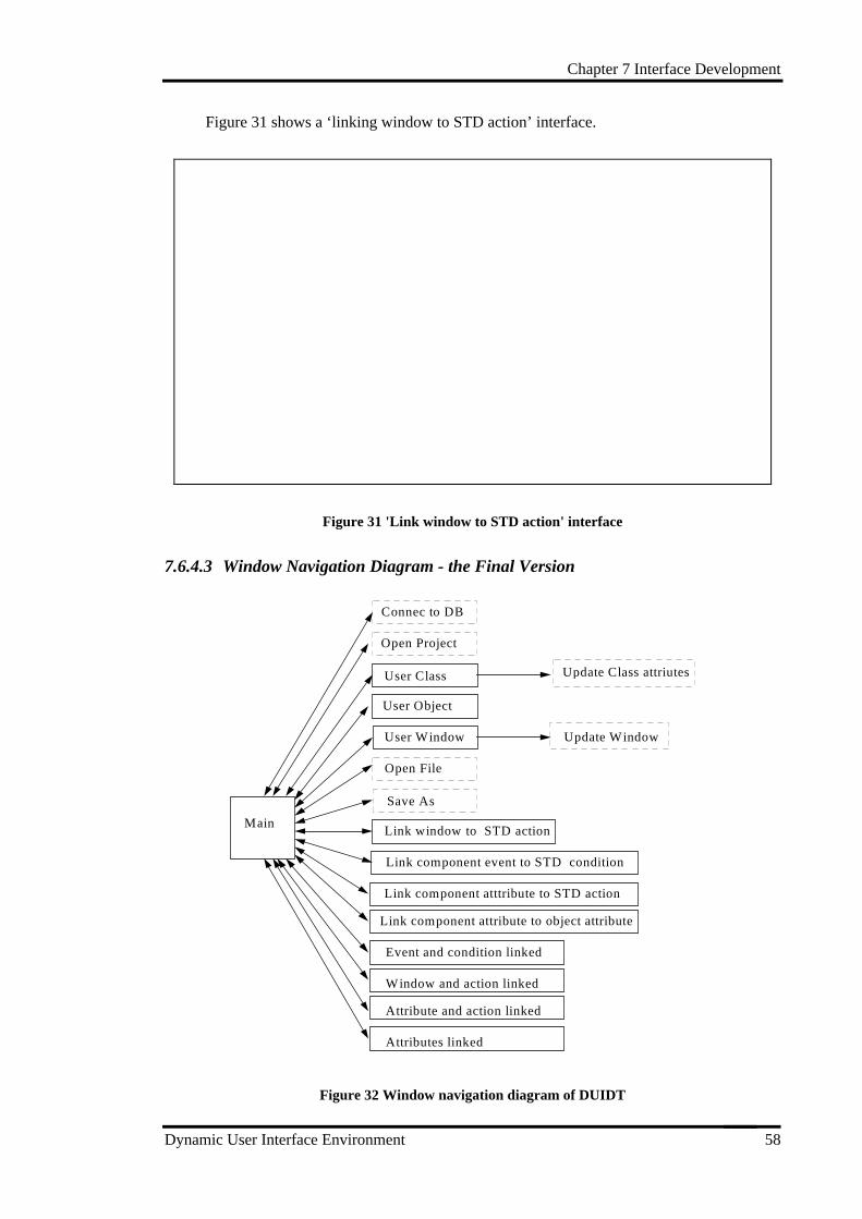
Chapter 7 Interface Development
Dynamic User Interface Environment 58
Figure 31 shows a ‘linking window to STD action’ interface.
Figure 31 'Link window to STD action' interface
7.6.4.3 Window Navigation Diagram - the Final Version
M ain
Connec to DB
User Class
Open Project
User Window
Open Fil e
L ink window to STD action
L ink component event to STD condition
L ink component attribute to object attribute
Update Class attriutes
User Object
Update Window
Save As
L ink component atttribute to STD action
Event and condition l inked
Window and action l inked
A ttribute and action linked
A ttributes l inked
Figure 32 Window navigation diagram of DUIDT
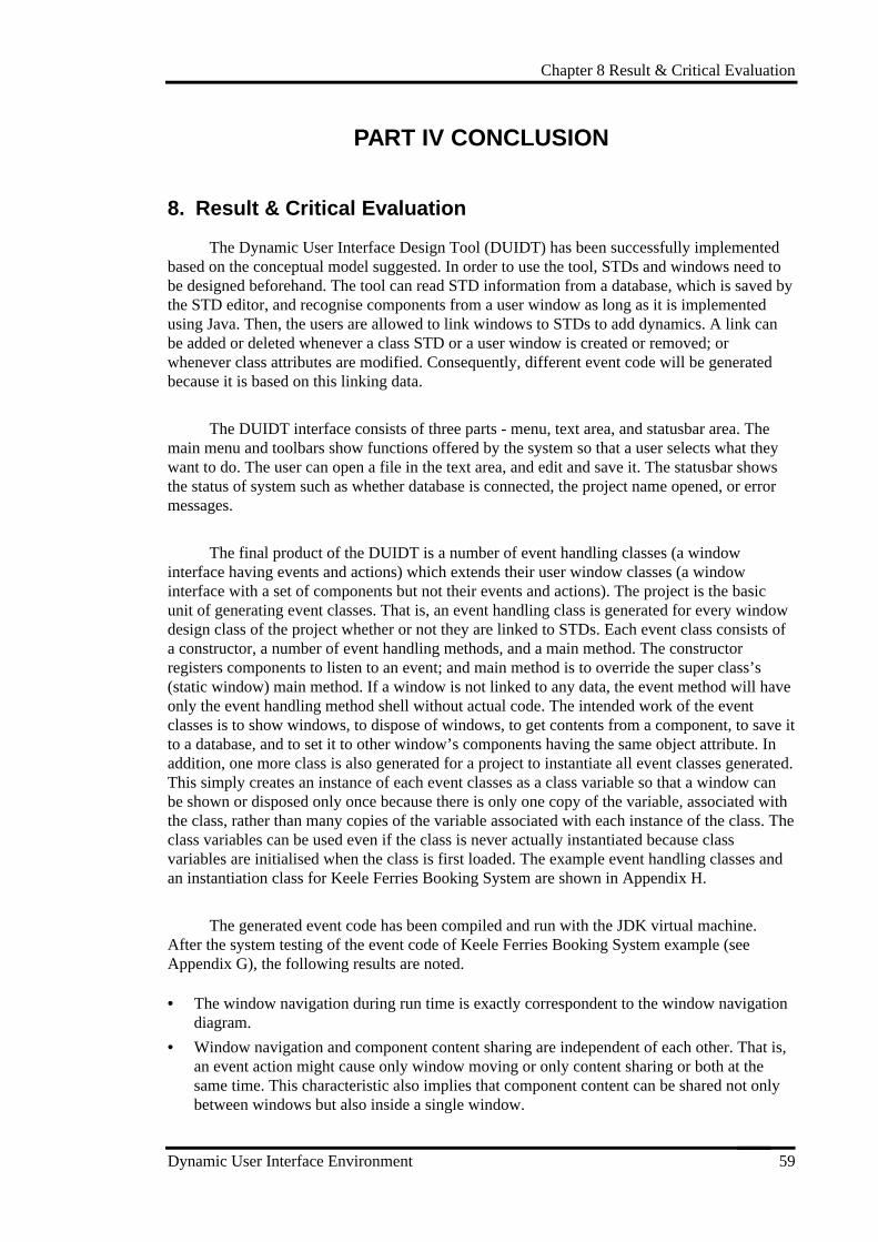
Chapter 8 Result & Critical Evaluation
Dynamic User Interface Environment 59
PART IV CONCLUSION
8. Result & Critical Evaluation
The Dynamic User Interface Design Tool (DUIDT) has been successfully implementedbased on the conceptual model suggested. In order to use the tool, STDs and windows need tobe designed beforehand. The tool can read STD information from a database, which is saved bythe STD editor, and recognise components from a user window as long as it is implementedusing Java. Then, the users are allowed to link windows to STDs to add dynamics. A link canbe added or deleted whenever a class STD or a user window is created or removed; orwhenever class attributes are modified. Consequently, different event code will be generatedbecause it is based on this linking data.
The DUIDT interface consists of three parts - menu, text area, and statusbar area. Themain menu and toolbars show functions offered by the system so that a user selects what theywant to do. The user can open a file in the text area, and edit and save it. The statusbar showsthe status of system such as whether database is connected, the project name opened, or errormessages.
The final product of the DUIDT is a number of event handling classes (a windowinterface having events and actions) which extends their user window classes (a windowinterface with a set of components but not their events and actions). The project is the basicunit of generating event classes. That is, an event handling class is generated for every windowdesign class of the project whether or not they are linked to STDs. Each event class consists ofa constructor, a number of event handling methods, and a main method. The constructorregisters components to listen to an event; and main method is to override the super class’s(static window) main method. If a window is not linked to any data, the event method will haveonly the event handling method shell without actual code. The intended work of the eventclasses is to show windows, to dispose of windows, to get contents from a component, to save itto a database, and to set it to other window’s components having the same object attribute. Inaddition, one more class is also generated for a project to instantiate all event classes generated.This simply creates an instance of each event classes as a class variable so that a window canbe shown or disposed only once because there is only one copy of the variable, associated withthe class, rather than many copies of the variable associated with each instance of the class. Theclass variables can be used even if the class is never actually instantiated because classvariables are initialised when the class is first loaded. The example event handling classes andan instantiation class for Keele Ferries Booking System are shown in Appendix H.
The generated event code has been compiled and run with the JDK virtual machine.After the system testing of the event code of Keele Ferries Booking System example (seeAppendix G), the following results are noted.
• The window navigation during run time is exactly correspondent to the window navigationdiagram.
• Window navigation and component content sharing are independent of each other. That is,an event action might cause only window moving or only content sharing or both at thesame time. This characteristic also implies that component content can be shared not onlybetween windows but also inside a single window.
Chapter 8 Result & Critical Evaluation
Dynamic User Interface Environment 60
• The content of a component can be shared by several other components of the samewindow, or by those of many other windows as long as they belong to the same objectattribute. Therefore, an action on a component (such as change of content) affects all otherrelated components.
It is a necessary and main part of the system to link windows to STDs to generate eventhandling code. However, this is time-consuming, difficult, and requires a lot of effort from theuser. Therefore, how the overhead of linking window to STD data can be reduced as much aspossible was the main area of concern during the project. In order to generate event code forwindow navigation and content sharing, four links need to be made. That is, the mainperformance of the system depends on the overhead of linking data. If a tool has a complicatedinterface for linking and is difficult to use, performing work is slow and can actually make thedevelopment process much less efficient. Developers may resist using the tool if it makes theirwork harder than it would have been to simply code the event handling method. So, the efforttrying to improve the interface for the linking of data has been especially emphasised ininterface development. The system design was also affected by this problem. Users often makean unwanted linking by mistake and will need to delete it. The system should allow the user tolink and delete data freely. This function is added in the second prototype of the system.
The restriction of the system is that the component member variables of a user windowdesign should not be private so that event handling class (subclass) can extend the user windowclass (super class). If a member variable of a super class is defined private, the generated eventhandling subclass cannot be compiled because it cannot access the variable of the super class.
Chapter 9 Conclusion
Dynamic User Interface Environment 61
9. Conclusion
Building a GUI design for a window-based system development is still a stimulatingchallenge. In addition to simply designing layout -the representational aspects- an interfacedesigner must link the screens and text to the functions of the system, and sequence theirscreens in order to describe operational aspects of an interface. Therefore, the development ofGUIs can be simplified and aided by using the appropriate tool. While static user interfacedesign is supported today by a wide range of interface design tools, there are few dynamic userinterface tools available. The purpose of this project was thus developing a dynamic userinterface tool which supports representing the behaviour of interface from a high levelspecification.
In this project, I have suggested a conceptual model showing that how dynamics can beadded into the static interface, and implemented the Dynamic User Interface Design Tool(DUIDT) based on the conceptual model. This conceptual model is based on object-orientedideas. The organisation and behaviour of user interface is mainly object-based. Defining userobjects tends to encourage the design of a separable user interface, where the appearance andbehaviour of interface components is only loosely coupled to underlying system functionality.This yields benefits in system construction, maintenance and enhancement. The conceptualmodel uses a state transition diagram for representing dynamics, and addresses two functionalbehaviours - window navigation and component content sharing. DUIDT achieves these goalswith two major features: linking static window designs to STD conditions and actions, andlinking windows to object attributes. It allows an extension of the representation (staticinterface) so that dynamics can be added to it; or of functionality of an earlier prototype alreadyhaving some behaviours, by generating object-oriented code for an application window designwhich can be extended by writing subclasses.
The tool has been demonstrated with a business system example - the Keele FerriesBooking System, for giving tips about how the tool could be used and for proving it works.User windows and STDs are designed based on the task analysis of a business domain. In orderto create a dynamic interface, the required linking was made by the user. The generateddynamic interface simulates performing task scenarios during runtime. For instance, if a‘booking’ button is clicked on the screen, the ‘booking’ window is popped up; or if customerdetails such as customer name, address, etc. are entered on the ‘booking’ window, thisinformation is automatically copied to the customer information fields of ‘holiday sitesbooking’ window when the related action is triggered.
The programming facility of the DUIDT automatically generates event handling code orat least part of the event handling methods. This is helpful because generated code is typicallymore consistent, and coding standards such as naming conventions and standard headers andcomments are maintained automatically. Also, generated event code contains fewer bugs, andcan be used for further programming during application development. In comparison toconventional techniques - programming by hand, this not only saves development time but canprovide a level of consistency across the different interfaces produced and allownonprogrammers and human factors engineers to contribute their expertise.
In terms of the software development life cycle, the developers are able to run the kind ofinvestigations which would normally be carried out much later in the life cycle of the project.There are cases where the resulting behaviour of a interface does not meet the designer’sexpectations even though the static forms are satisfied. So, the correctness of its dynamic
Chapter 9 Conclusion
Dynamic User Interface Environment 62
behaviour still needs to be confirmed. End users can evaluate each prototype and providefeedback, increasing their satisfaction with the final product.
The tool would be more useful when it can be used in combination with static designtools for building user interface in the system development. A static interface designer definesthe internal structure of a system by declaring the graphical appearance such as its position,colour, height, layout, and so on. Then, dynamic behaviour can be added on this designedinterface. For example, an interface designer might use Semantic Cafe to design the Java staticinterface, and DUIDT for generating the dynamic interface. This will save the designer’s timeand make his or her work easier by reducing time-consuming coding. Besides the staticinterface builders, DUIDT can be used in cooperation with other kinds of interfacedevelopment tools such as the STD editor used in this project to draw a state transition diagram.
To conclude, the results of this project suggest that the introduction of such tools into asoftware development environment would improve software development processes but not at acost of making the interface more annoying. However the tool is not a general purpose visualstate diagram programming system. Rather, it offers a set of domain specific, high-levelabstraction services for creating a dynamic interface. The design method for developing adynamic tool proposed here tries to overcome some of the problems found in current practice ofuser interface design, i.e., the lack of behavioural design. This is done by making a strongerconnection between the behavioural design and the user interface design, by reuse of staticinterface design (by using inheritance of object-oriented concept), and by automation of thetranslation between behavioural design specifications and user interface layout specifications.
Currently, the tool uses textual linking in order to link windows to STD information.Textual linking is less understandable than graphical linking. A graphical display has theadvantage of letting you grasp aspects of parallel execution more immediately and moreaccurately than a textual interface. Developing a graphical tool which supports the linking ofstatic user interface design and state transition diagram in a graphical manner would have anobvious advantage. This will make linking easier, faster, and more understandable than textuallinking.
Another suggested future work is developing an integrated methodology for both systemand interface development. There are many system development methodologies, and a fewinterface development methodologies. However, there are no applicable methodologies whichsupport processes and guides for both system and interface development. Most current systemdevelopment methodologies do not deal with the interface at all. The GUIDE methodology usedin this project for the interface development suggests the linkage between system and interfacedevelopment and some processes needs to be done, but it is not enough as a complete systemdevelopment methodology. That is why the functions and interface of the system had to bedeveloped independently with different methodologies. Since most modern applications usegraphical user interfaces, it would be worthwhile developing an integrated developmentmethodology.
Bibliography
Dynamic User Interface Environment 63
Bibliography
Bischofberger, W. & Pomberger, G., Prototyping-Oriented Software Development:Concept andTools, Springer-Verlag,1992.
Budgen, David, Software Design, Addison-Wesley, 1994.
Cornell, Gary & Horstmann, Cay S. Core Java, 2nd ed., Sun Softpress: A Prentice Hall, 1997.
Downton, Andy, Engineering the Human-Computer Interface, Dept of Electronic SystemsEngineering, Imniv. of Essex, McFraw-Hill, 1991.
Eberts, R. E., User Interface Design, Prentice-Hall, 1994.
Esteban, O. & Chatty, S. & Palanque, P., “WHIZZ’ED: A Visual Environment for BuildingHighly”, Human-Computer Interaction Interact ‘95, Chapman & Hall 1995, p. 121-126.
Flanagan, D., Java in a Nutshell: A Desktop Quick Reference, 2nd. ed., O’REILLY, 1996
Harel, David, “Statecharts: A Visual Formalism for Complex Systems”, Science of ComputerProgramming, 8 (North-Holland, 1987), p 231-274.
Kimgour, A. & Earnshaw, R., Graphics Tools for Software Engineers, the Press Syndicate ofthe University of Cambridge, 1989
Lamb, David A., Software Engineering: Planning for Change, Prentice-Hall InternationalEditions, 1998, p. 109.
Lauridsen, O., “Generation of User Interfaces Using Formal Specification”, Human-ComputerInteraction Interact ‘95, Chapman & Hall 1995, p121-126
Newman, William M. & Lamming, Michael G. Interactive System Design, Addison-Wesley,1995.
Pfleeger, Shari L., Software Engineering:The Production of Quality Software, 2nd ed. MaxwellMacmillan Internaltilnal editions, 1991, p. 291.
Popping, M. & Szwillus, G., “Constraint-Based Definition of Application-Specific Graphics”,Human-Computer Interaction Interact ‘95, Chapman & Hall, (1995), p. 85-90.
Preece, Jenny, A Guide to Usability:Human Factors in Computing, Addison-Wesley, 1993.
Redmond-Pyle, D. & Moore, A., Graphical User Interface Design and Evaluation: A PracticalProcess, Prentice Hall, 1995.
Rumbaugh, J.& Blaha, M., etc., Object-Oreiented Modelling and Design, Prentice-Hall, 1991.
Seats, A. & Lund, A.M., “Creating Effective User Interface”, IEEE Software, July/August(1997), p. 21-24.
Shneiderman, B. Desiging the User Interface: Strategies for Effective Human-ComputerInteraction, 2nd ed., Addison-Wesley, 1992.
Valaer, L.A. & Babb, R., “Choosing a User Interface Development Tool”, IEEE Software,July/August, (1997).
Vanhelsuwe L. and etc. Mastering Java 1.1, 2nd ed., SYBES, 1997.
Ward Paul T. & Mellor Stephen J., Structured Development for Real-Time Systems, YourdonPress Prentice Hall, 1985.
Yourdon E., Modern Structured Analysis, Prentice-Hall, 1989.
http://java.sun.com/, (Java SUN web page)
http://java.sun.com/products/jdk/1.1/docs/api/packages.html, (Java JDK 1.1.4 Core API)
http://www.rational.com/uml/references/notation-guide.html/, (UML notation guide, Rationalsoftware corporation)
http://www.java.sun.com/ docs/books/tutorial/, (Java Internet Tutorial)
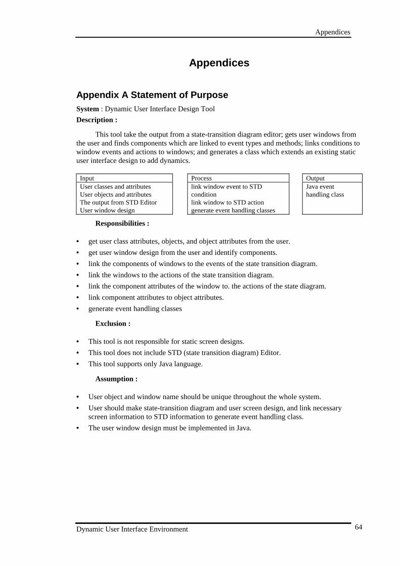
Appendices
Dynamic User Interface Environment 64
Appendices
Appendix A Statement of PurposeSystem : Dynamic User Interface Design Tool
Description :
This tool take the output from a state-transition diagram editor; gets user windows fromthe user and finds components which are linked to event types and methods; links conditions towindow events and actions to windows; and generates a class which extends an existing staticuser interface design to add dynamics.
Input Process OutputUser classes and attributesUser objects and attributesThe output from STD EditorUser window design
link window event to STDconditionlink window to STD actiongenerate event handling classes
Java eventhandling class
Responsibilities :
• get user class attributes, objects, and object attributes from the user.
• get user window design from the user and identify components.
• link the components of windows to the events of the state transition diagram.
• link the windows to the actions of the state transition diagram.
• link the component attributes of the window to. the actions of the state diagram.
• link component attributes to object attributes.
• generate event handling classes
Exclusion :
• This tool is not responsible for static screen designs.
• This tool does not include STD (state transition diagram) Editor.
• This tool supports only Java language.
Assumption :
• User object and window name should be unique throughout the whole system.
• User should make state-transition diagram and user screen design, and link necessaryscreen information to STD information to generate event handling class.
• The user window design must be implemented in Java.
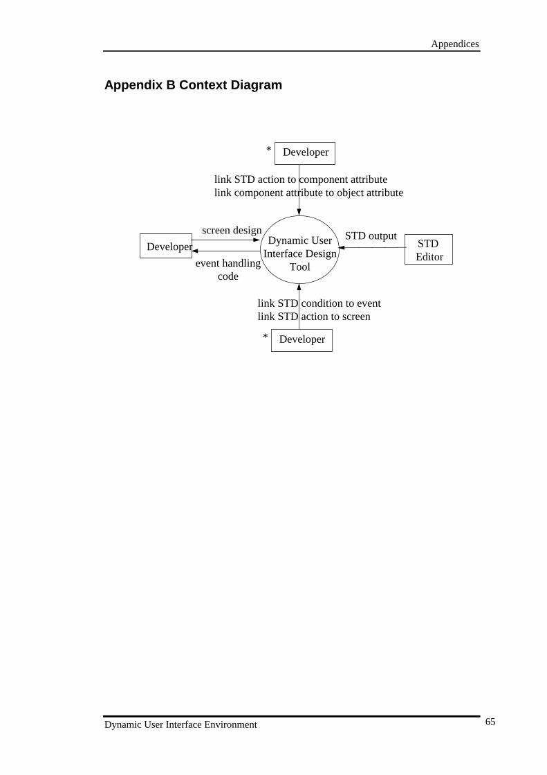
Appendices
Dynamic User Interface Environment 65
Appendix B Context Diagram
Dynamic UserInterface Design
Tool
Developer
Developer
STD Editor
screen design
event handlingcode
link STD action to component attributelink component attribute to object attribute
link STD condition to eventlink STD action to screen
STD output
Developer*
*
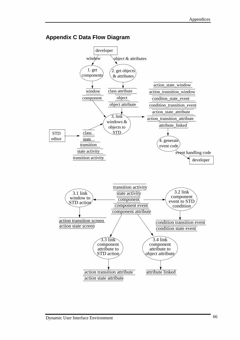
Appendices
Dynamic User Interface Environment 66
Appendix C Data Flow Diagram
4. generateevent code
3. linkwindows &objects to
STDSTDeditor
developer
developer
1. getcomponents
window
event handling code
2. get objects& attributes
attribute_linked
action_state_window
action_transition_window
condition_transition_event
conditon_state_event
object & attributes
component
window class attribute
object
object attribute
class
statetransition
state activity
transition activity
action_state_attribute
action_transition_attribute
3.1 linkwindow toSTD action
3.2 linkcomponent
event to STDconditioncomponent event
transition activitystate activitycomponent
action transition screenaction state screen
condition transition eventcondition state event
3.3 linkcomponentattribute toSTD action
3.4 linkcomponentattribute to
object attribute
component attribute
action transition attributeaction state attribute
attribute linked
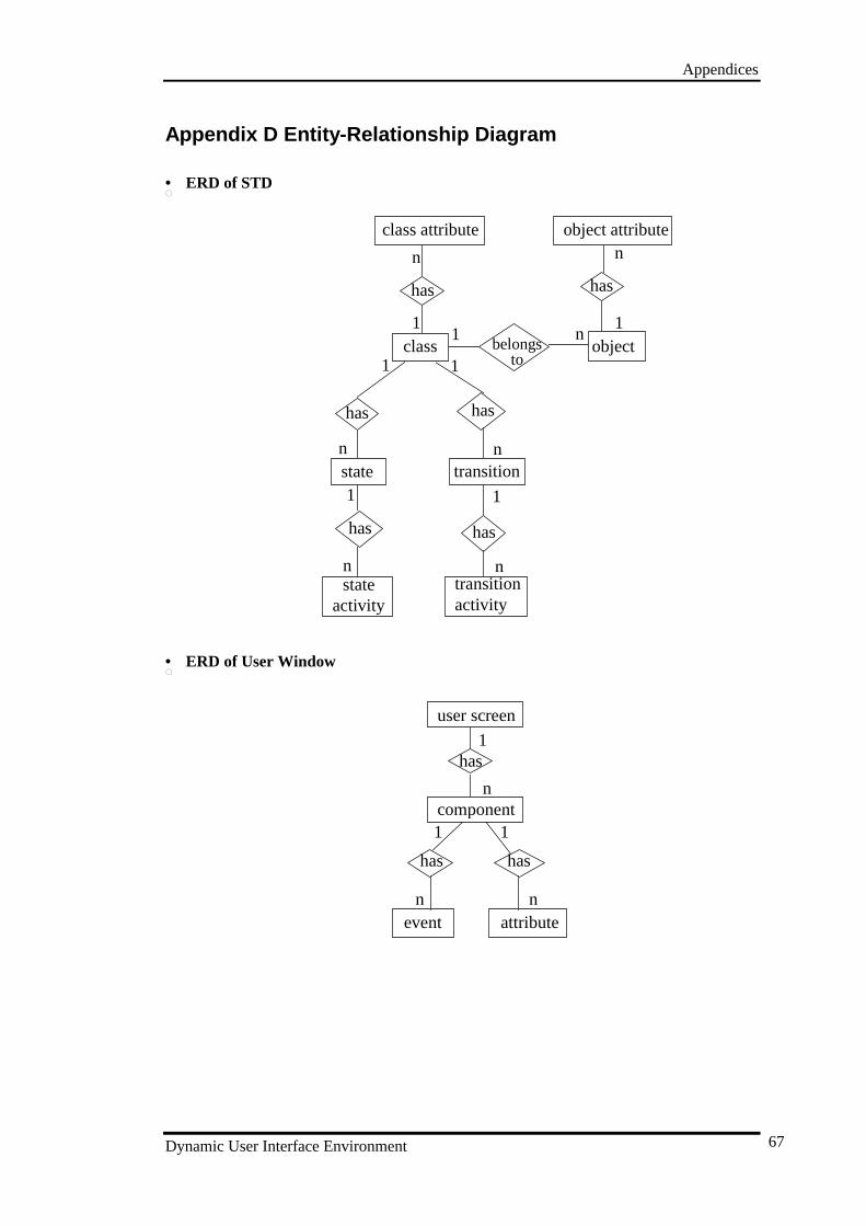
Appendices
Dynamic User Interface Environment 67
Appendix D Entity-Relationship Diagram
• • ERD of STD
state transition
stateactivity
class object
has
has
has
class attribute object attribute
has has
1
n
11
n
1
n
transitionactivity
has
1
n
1
n
n
1
nbelongs
to
• • ERD of User Window
user screen
component
event
has
has
has
attribute
1
n
1
n
1
n
Appendices
Dynamic User Interface Environment 68
• • ERD of Linking data of User window and STD
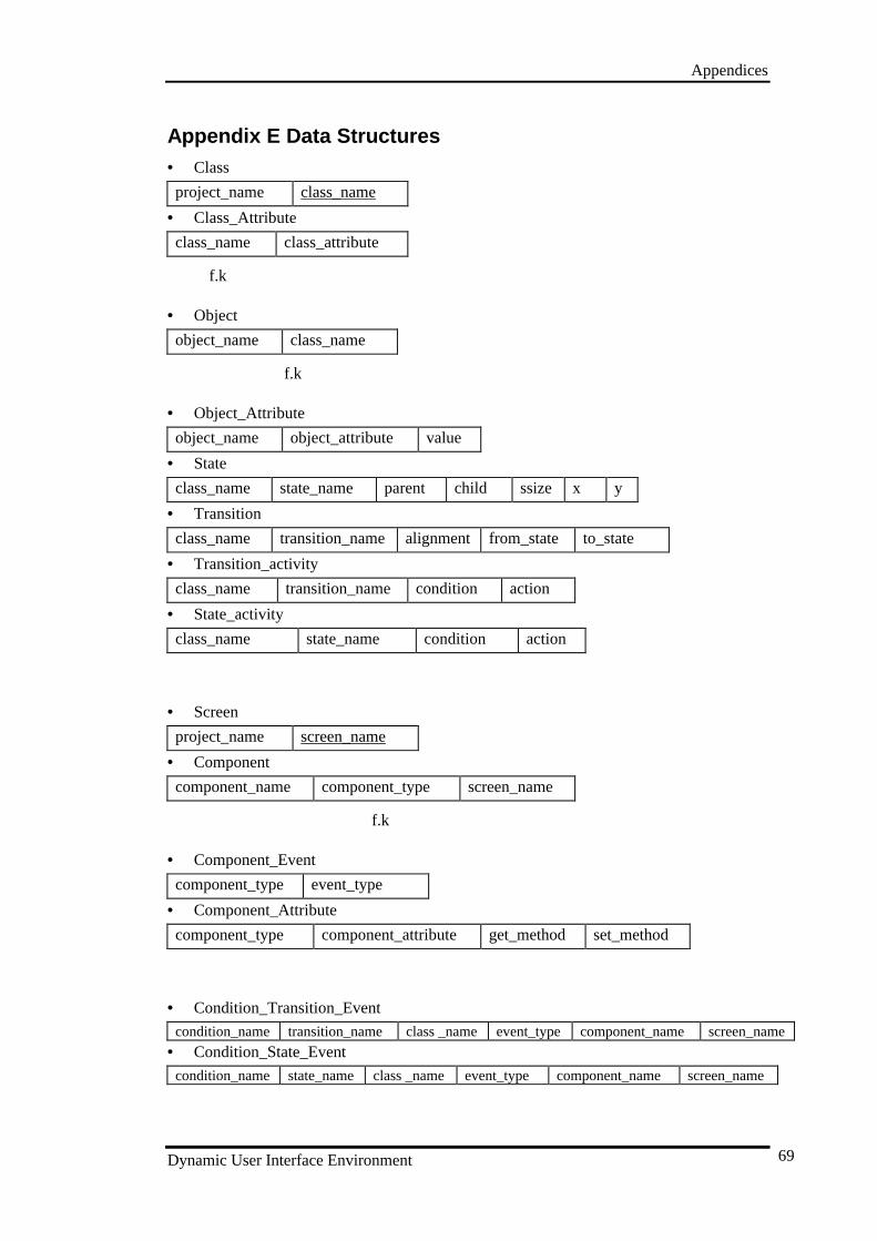
Appendices
Dynamic User Interface Environment 69
Appendix E Data Structures• Class
project_name class_name
• Class_Attribute
class_name class_attribute
f.k
• Object
object_name class_name
f.k
• Object_Attribute
object_name object_attribute value
• State
class_name state_name parent child ssize x y
• Transition
class_name transition_name alignment from_state to_state
• Transition_activity
class_name transition_name condition action
• State_activity
class_name state_name condition action
• Screen
project_name screen_name
• Component
component_name component_type screen_name
f.k
• Component_Event
component_type event_type
• Component_Attribute
component_type component_attribute get_method set_method
• Condition_Transition_Event
condition_name transition_name class _name event_type component_name screen_name
• Condition_State_Event
condition_name state_name class _name event_type component_name screen_name
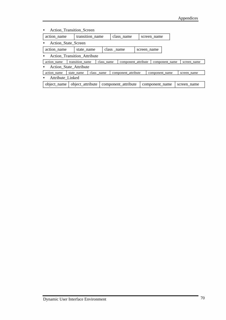
Appendices
Dynamic User Interface Environment 70
• Action_Transition_Screen
action_name transition_name class_name screen_name
• Action_State_Screen
action_name state_name class _name screen_name
• Action_Transition_Attributeaction_name transition_name class_name component_attribute component_name screen_name
• Action_State_Attributeaction_name state_name class _name component_attribute component_name screen_name
• Attribute_Linked
object_name object_attribute component_attribute component_name screen_name
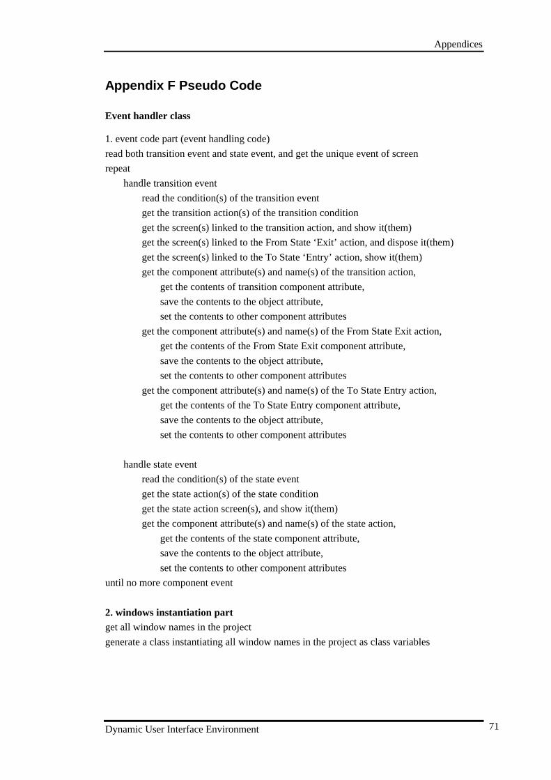
Appendices
Dynamic User Interface Environment 71
Appendix F Pseudo Code
Event handler class
1. event code part (event handling code)
read both transition event and state event, and get the unique event of screen
repeat
handle transition event
read the condition(s) of the transition event
get the transition action(s) of the transition condition
get the screen(s) linked to the transition action, and show it(them)
get the screen(s) linked to the From State ‘Exit’ action, and dispose it(them)
get the screen(s) linked to the To State ‘Entry’ action, show it(them)
get the component attribute(s) and name(s) of the transition action,
get the contents of transition component attribute,
save the contents to the object attribute,
set the contents to other component attributes
get the component attribute(s) and name(s) of the From State Exit action,
get the contents of the From State Exit component attribute,
save the contents to the object attribute,
set the contents to other component attributes
get the component attribute(s) and name(s) of the To State Entry action,
get the contents of the To State Entry component attribute,
save the contents to the object attribute,
set the contents to other component attributes
handle state event
read the condition(s) of the state event
get the state action(s) of the state condition
get the state action screen(s), and show it(them)
get the component attribute(s) and name(s) of the state action,
get the contents of the state component attribute,
save the contents to the object attribute,
set the contents to other component attributes
until no more component event
2. windows instantiation partget all window names in the project
generate a class instantiating all window names in the project as class variables
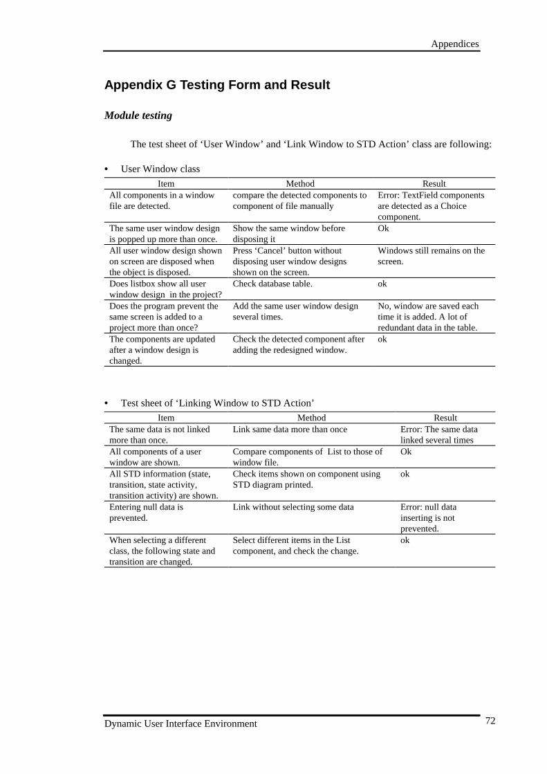
Appendices
Dynamic User Interface Environment 72
Appendix G Testing Form and Result
Module testing
The test sheet of ‘User Window’ and ‘Link Window to STD Action’ class are following:
• User Window class
Item Method ResultAll components in a windowfile are detected.
compare the detected components tocomponent of file manually
Error: TextField componentsare detected as a Choicecomponent.
The same user window designis popped up more than once.
Show the same window beforedisposing it
Ok
All user window design shownon screen are disposed whenthe object is disposed.
Press ‘Cancel’ button withoutdisposing user window designsshown on the screen.
Windows still remains on thescreen.
Does listbox show all userwindow design in the project?
Check database table. ok
Does the program prevent thesame screen is added to aproject more than once?
Add the same user window designseveral times.
No, window are saved eachtime it is added. A lot ofredundant data in the table.
The components are updatedafter a window design ischanged.
Check the detected component afteradding the redesigned window.
ok
• Test sheet of ‘Linking Window to STD Action’
Item Method ResultThe same data is not linkedmore than once.
Link same data more than once Error: The same datalinked several times
All components of a userwindow are shown.
Compare components of List to those ofwindow file.
Ok
All STD information (state,transition, state activity,transition activity) are shown.
Check items shown on component usingSTD diagram printed.
ok
Entering null data isprevented.
Link without selecting some data Error: null datainserting is notprevented.
When selecting a differentclass, the following state andtransition are changed.
Select different items in the Listcomponent, and check the change.
ok
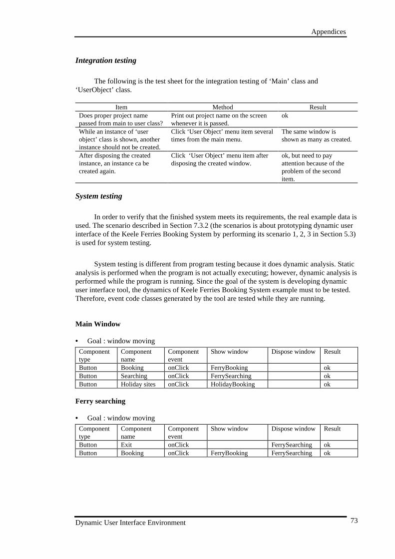
Appendices
Dynamic User Interface Environment 73
Integration testing
The following is the test sheet for the integration testing of ‘Main’ class and‘UserObject’ class.
Item Method ResultDoes proper project namepassed from main to user class?
Print out project name on the screenwhenever it is passed.
ok
While an instance of ‘userobject’ class is shown, anotherinstance should not be created.
Click ‘User Object’ menu item severaltimes from the main menu.
The same window isshown as many as created.
After disposing the createdinstance, an instance ca becreated again.
Click ‘User Object’ menu item afterdisposing the created window.
ok, but need to payattention because of theproblem of the seconditem.
System testing
In order to verify that the finished system meets its requirements, the real example data isused. The scenario described in Section 7.3.2 (the scenarios is about prototyping dynamic userinterface of the Keele Ferries Booking System by performing its scenario 1, 2, 3 in Section 5.3)is used for system testing.
System testing is different from program testing because it does dynamic analysis. Staticanalysis is performed when the program is not actually executing; however, dynamic analysis isperformed while the program is running. Since the goal of the system is developing dynamicuser interface tool, the dynamics of Keele Ferries Booking System example must to be tested.Therefore, event code classes generated by the tool are tested while they are running.
Main Window
• Goal : window moving
Componenttype
Componentname
Componentevent
Show window Dispose window Result
Button Booking onClick FerryBooking okButton Searching onClick FerrySearching okButton Holiday sites onClick HolidayBooking ok
Ferry searching
• Goal : window moving
Componenttype
Componentname
Componentevent
Show window Dispose window Result
Button Exit onClick FerrySearching okButton Booking onClick FerryBooking FerrySearching ok
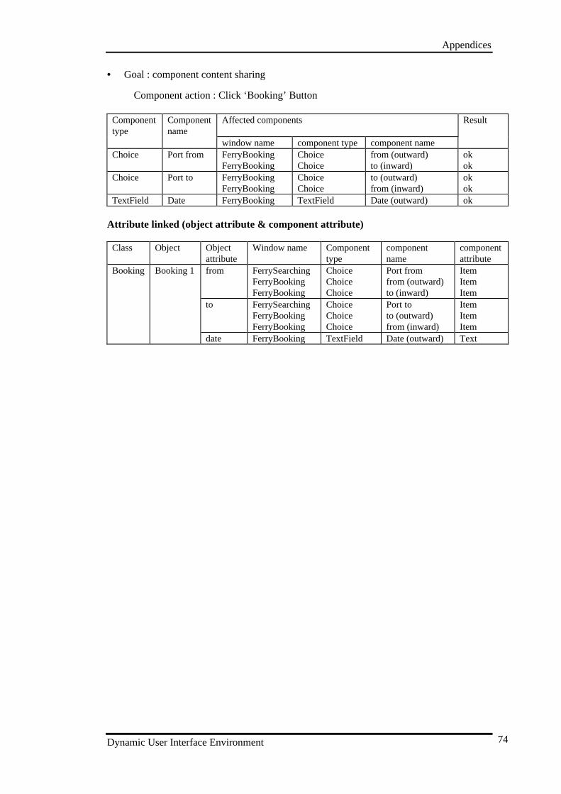
Appendices
Dynamic User Interface Environment 74
• Goal : component content sharing
Component action : Click ‘Booking’ Button
Componenttype
Componentname
Affected components Result
window name component type component nameChoice Port from FerryBooking
FerryBookingChoiceChoice
from (outward)to (inward)
okok
Choice Port to FerryBookingFerryBooking
ChoiceChoice
to (outward)from (inward)
okok
TextField Date FerryBooking TextField Date (outward) ok
Attribute linked (object attribute & component attribute)
Class Object Objectattribute
Window name Componenttype
componentname
componentattribute
Booking Booking 1 from FerrySearchingFerryBookingFerryBooking
ChoiceChoiceChoice
Port fromfrom (outward)to (inward)
ItemItemItem
to FerrySearchingFerryBookingFerryBooking
ChoiceChoiceChoice
Port toto (outward)from (inward)
ItemItemItem
date FerryBooking TextField Date (outward) Text
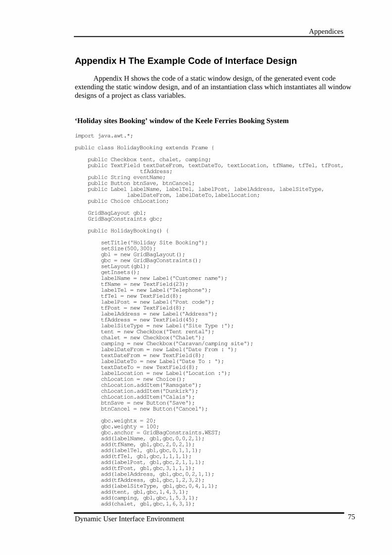
Appendices
Dynamic User Interface Environment 75
Appendix H The Example Code of Interface Design
Appendix H shows the code of a static window design, of the generated event codeextending the static window design, and of an instantiation class which instantiates all windowdesigns of a project as class variables.
‘Holiday sites Booking’ window of the Keele Ferries Booking System
import java.awt.*;
public class HolidayBooking extends Frame {
public Checkbox tent, chalet, camping;public TextField textDateFrom, textDateTo, textLocation, tfName, tfTel, tfPost,
tfAddress;public String eventName;public Button btnSave, btnC ancel;public Label labelName, labelTel, labelPost, labelAddress, labelSiteType,
labelDateFrom, labelDateTo,labelLocation;public Choice chLocation;
GridBagLayout gbl;GridBagConstraints gbc;
public HolidayBooking() {
setTitle("Holiday Site Booking");setSize(500,300);gbl = new GridBagLayout();gbc = new GridBagConstraints();setLayout(gbl);getInsets();labelName = new Label("Customer name");tfName = new TextField(23);labelTel = new Label("Telephone");tfTel = new TextField(8);labelPost = new Label("Post code");tfPost = new TextField(8);labelAddress = new Label("Address");tfAddress = new TextField(45);labelSiteType = new Label("Site Type :");tent = new Checkbox("Tent rental");chalet = new Checkbox("Chalet");camping = new Checkbox("Caravan/camping site");labelDateFrom = new Label("Date From : ");textDateFrom = new TextField(8);labelDateTo = new Label("Date To : ");textDateTo = new TextField(8);labelLocation = new Label("Location :");chLocation = new Choice();chLocation.addItem("Ramsgate");chLocation.addItem("Dunkirk");chLocation.addItem("Calais");btnSave = new Button("Save");btnCancel = new Button("Cancel");
gbc.weightx = 20;gbc.weighty = 100;gbc.anchor = GridBagConstraints.WEST;add(labelName, gbl,gbc,0,0,2,1);add(tfName, gbl,gbc,2,0,2,1);add(labelTel, gbl,gbc,0,1,1,1);add(tfTel, gbl,gbc,1,1,1,1);add(labelPost, gbl,gbc,2,1,1,1);add(tfPost, gbl,gbc,3,1,1,1);add(labelAddress, gbl, gbc,0,2,1,1);add(tfAddress, gbl,gbc,1,2,3,2);add(labelSiteType, gbl,gbc,0,4,1,1);add(tent, gbl,gbc,1,4,3,1);add(camping, gbl,gbc,1,5,3,1);add(chalet, gbl,gbc,1,6,3,1);
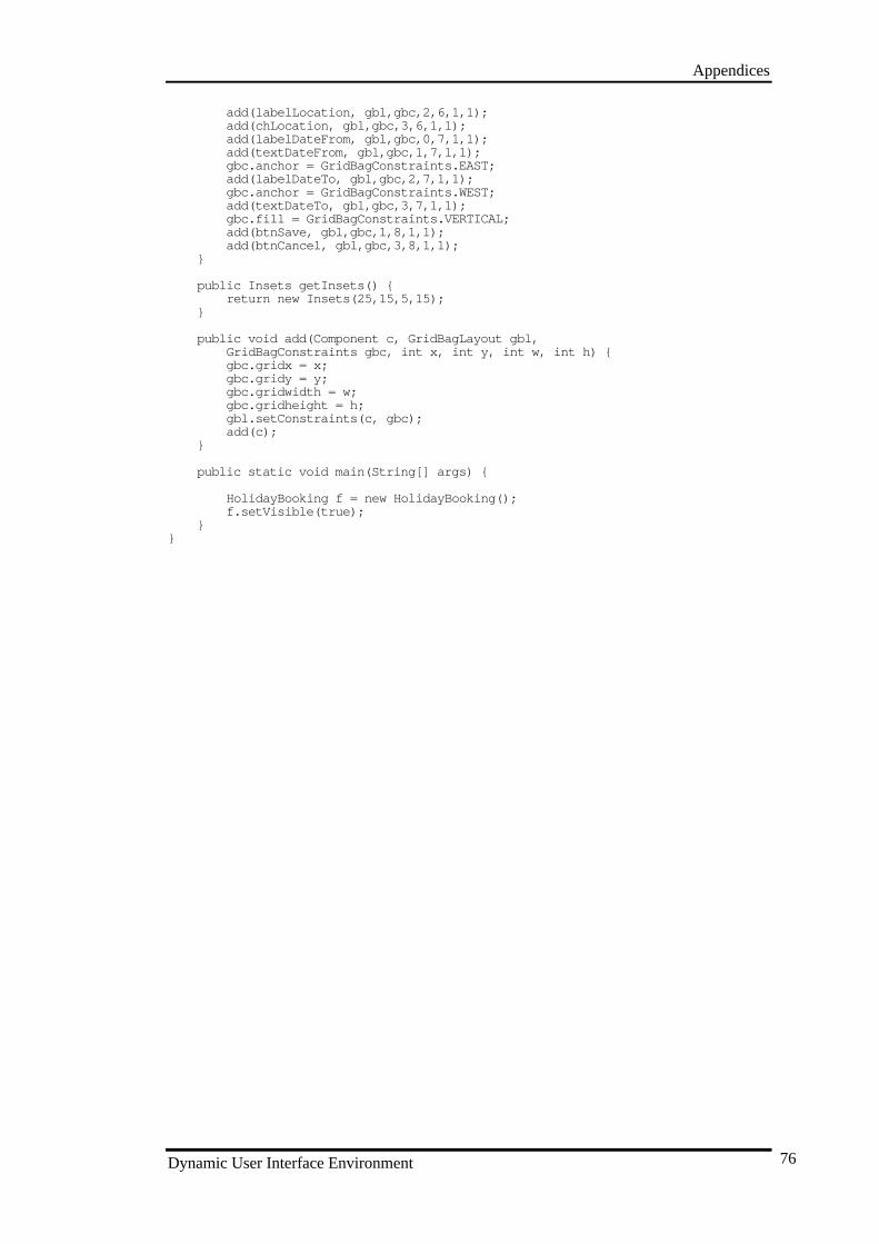
Appendices
Dynamic User Interface Environment 76
add(labelLocation, gbl,gbc,2,6,1,1);add(chLocation, gbl,gbc,3,6,1,1);add(labelDateFrom, gbl,gbc,0,7,1,1);add(textDateFrom, gbl,gbc,1,7,1,1);gbc.anchor = GridBagConstraints.EAST;add(labelDateTo, gbl,gbc,2,7,1,1);gbc.anchor = GridBagConstraints.WEST;add(textDateTo, gbl,gbc,3,7,1,1);gbc.fill = GridBagC onstraints.VERTICAL;add(btnSave, gbl,gbc,1,8,1,1);add(btnCancel, gbl,gbc,3,8,1,1);
}
public Insets getInsets() {return new Insets(25,15,5,15);
}
public void add(Component c, GridBagLayout gbl,GridBagConstraints gbc, int x, int y, int w, int h) {gbc.gridx = x;gbc.gridy = y;gbc.gridwidth = w;gbc.gridheight = h;gbl.setConstraints(c, gbc);add(c);
}
public static void main(String[] args) {
HolidayBooking f = new HolidayBooking();f.setVisible(true);
}}
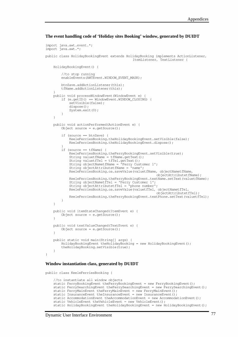
Appendices
Dynamic User Interface Environment 77
The event handling code of ‘Holiday sites Booking’ window, generated by DUIDT
import java.awt.event.*;import java.awt.*;
public class HolidayBookingEvent extends HolidayBooking implements ActionListener, ItemListener, TextListener {
HolidayBookingEvent() {
//to stop runningenableEvents(AWTEvent.WINDOW_EVENT_MASK);
btnSave.addActionListener(this);tfName.addActionListener(this);
}public void processWindowEvent(WindowEvent e) {
if (e.getID() == WindowEvent.WINDOW_CLOSING) {setVisi ble(false);dispose();System.exit(0);
}}
public void actionPerformed(ActionEvent e) {Object source = e.getSource();
if (source == btnSave) {KeeleFerriesBooking.theHolidayBookingEvent.setVisible(false);KeeleFerriesBooking.theHolidayBookingEvent.dispose();
}if (source == tfName) {
KeeleFerriesBooking.theFerryBookingEvent.setVisible(true);String valuetfName = tfName.getText();String valuetfTel = tfTel.getText();String objectNametfName = "Ferry Customer 1";Stri ng objectAttributetfName = "name";KeeleFerriesBooking.oa.saveValue(valuetfName, objectNametfName,
objectAttributetfName);KeeleFerriesBooking.theFerryBookingEvent.textName.setText(valuetfName);String objectNametfTel = "Ferry Customer 1";String objectAttributetfTel = "phone number";KeeleFerriesBooking.oa.saveValue(valuetfTel, objectNametfTel,
objectAttributetfTel);KeeleFerriesBooking.theFerryBookingEvent.textPhone.setText(valuetfTel);
}}
public v oid itemStateChanged(ItemEvent e) {Object source = e.getSource();
}
public void textValueChanged(TextEvent e) {Object source = e.getSource();
}
public static void main(String[] args) {HolidayBookingEvent theHolidayBooking = new HolidayBookingEvent();theHolidayBooking.setVisible(true);
}}
Window instantiation class, generated by DUIDT
public class KeeleFerriesBooking {
//to instantiate all window objectsstatic FerryBookingEvent theFerryBookingEvent = new FerryBookingEvent();static F errySearchingEvent theFerrySearchingEvent = new FerrySearchingEvent();static FerryMainEvent theFerryMainEvent = new FerryMainEvent();static InsuranceEvent theInsuranceEvent = new InsuranceEvent();static AccommodationEvent theAccommodationEvent = new AccommodationEvent();static VehicleEvent theVehicleEvent = new VehicleEvent();static HolidayBookingEvent theHolidayBookingEvent = new HolidayBookingEvent();
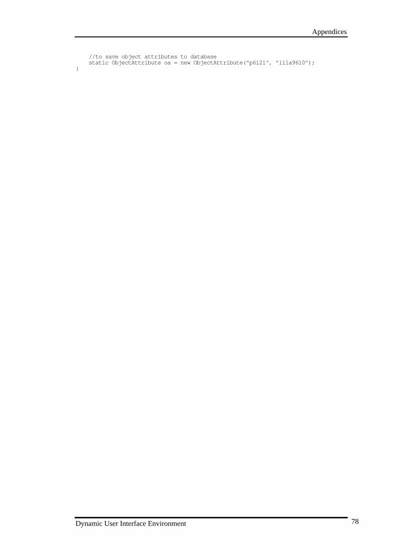
Appendices
Dynamic User Interface Environment 78
//to save object attributes to databasestatic ObjectAttribute oa = new ObjectAttribute("p6i 21", "lila9610");
}
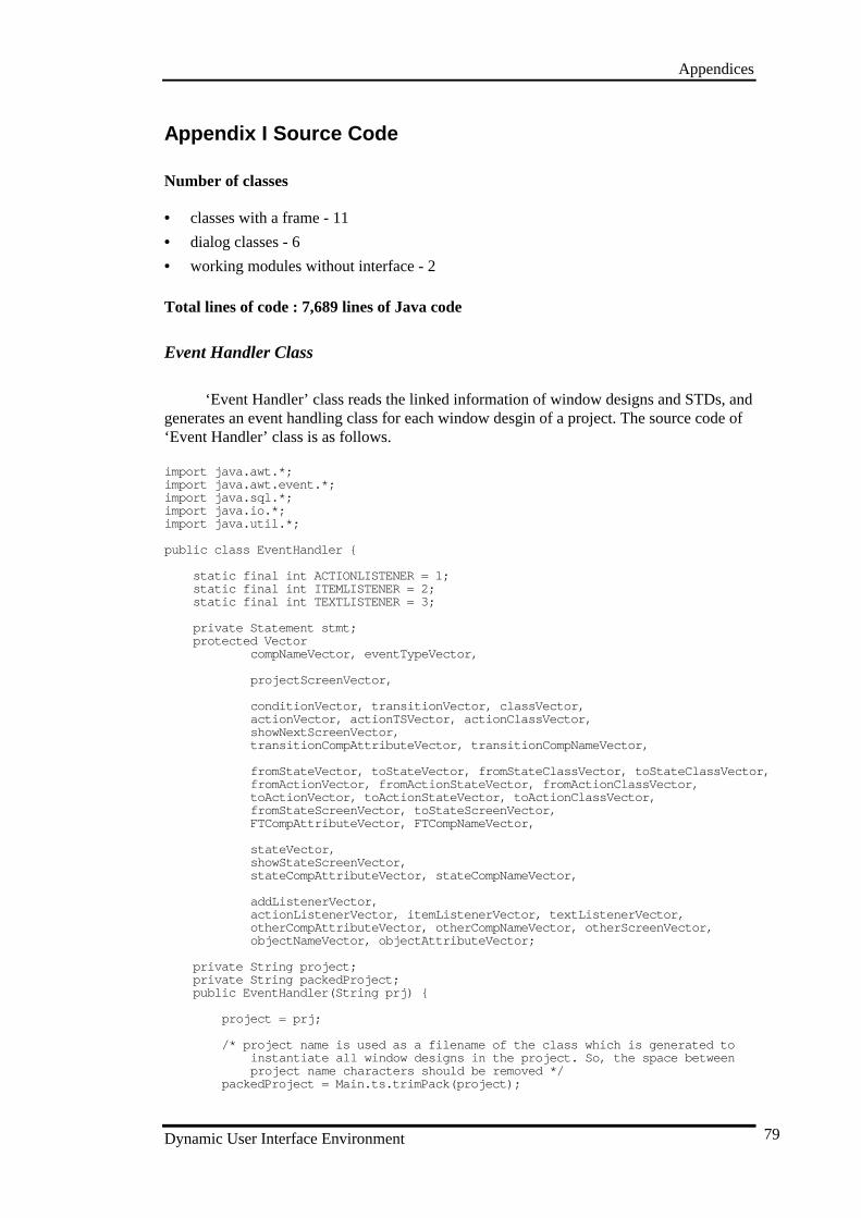
Appendices
Dynamic User Interface Environment 79
Appendix I Source Code
Number of classes
• classes with a frame - 11
• dialog classes - 6
• working modules without interface - 2
Total lines of code : 7,689 lines of Java code
Event Handler Class
‘Event Handler’ class reads the linked information of window designs and STDs, andgenerates an event handling class for each window desgin of a project. The source code of‘Event Handler’ class is as follows.
import java.awt.*;import java.awt.event.*;import java.sql.*;import java.io.*;import java.util.*;
public class EventHandler {
static final int ACTIONLISTENER = 1;static final int ITEMLISTENER = 2;static final int TEXTLISTENER = 3;
private Statement stmt;protected Vector
compNameVector, eventTypeVector,
projectScreenVector,
conditionVector, transitionVector, classVector,actionVector, actionTSVector, actionClassVector,showNextScreenVector,transitionCompAttributeVector, transitionCompNameVector,
fromStateVector, toStateVector, fromStateClassV ector, toStateClassVector,fromActionVector, fromActionStateVector, fromActionClassVector,toActionVector, toActionStateVector, toActionClassVector,fromStateScreenVector, toStateScreenVector,FTCompAttributeVector, FTCompNameVector,
stateVector,showStateScreenVector,stateCompAttributeVector, stateCompNameVector,
addListenerVector,actionListenerVector, itemListenerVector, textListenerVector,otherCompAttributeVector, otherCompNameVector, otherScreenVector,objectNameVector, objectAttributeVector;
private String project;private String packedProject;public EventHandler(String prj) {
project = prj;
/* project name is used as a filename of the class which is generated to instantiate all window designs in the project. So, the space between project name characters should be removed */
packedProject = Main.ts.trimPack(project);
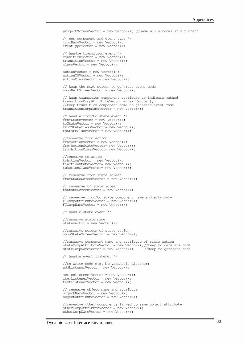
Appendices
Dynamic User Interface Environment 80
projectScreenVector = new Vector(); //save all windows in a project
/* set component and event type */compNameVector = new Vector();eventTypeVector = new Vector();
/* handle transition event */conditionVector = new Vector();transitionVector = new Vector();classVector = new Vector();
actionVector = new Vector();actionTSVector = new Vector();actionClassVector = new Vector();
// keep the next screen to generate event codeshowNextScreenVector = new Vector();
// keep transition component attribute to indicate methodtransitionCompAttributeVector = new Ve ctor();//keep transition component name to generate event codetransitionCompNameVector = new Vector();
/* handle from/to state event */fromStateVector = new Vector();toStateVector = new Vector();fromStateClassVector = new Vector();toStateClassVector = new Vector();
//researve from actionfromActionVector = new Vector();fromActionStateVector= new Vector();fromActionClassVector= new Vector();
//researve to actiontoActionVector = new Vector();toActionStateVect or= new Vector();toActionClassVector= new Vector();
// researve from state screenfromStateScreenVector = new Vector();
// researve to state screentoStateScreenVector = new Vector();
// researve from/to state component name and attributeFTCompAttributeVector = new Vector();FTCompNameVector = new Vector();
/* handle state event */
//researve state namestateVector = new Vector();
//researve screen of state actionshowStateScreenVector = new Vector();
//researve component name and attribute of state actionstateCompAttributeVector = new Vector(); //keep to generate codestateCompNameVector = new Vector(); //keep to generate code
/* handle event listener */
//to write code e.g. btn.addActionListener;addListenerVector = new Vector();
actionListenerVector = new Vector();itemListenerVector = new Vector();textListenerVector = new Vector();
// researve object name and attributeobjectNameVector = new Vector();objectAttributeVector = new Vector();
//researve other components linked to same object attributeotherCompAttributeVector = new Vector();otherCompNameVector = new Vector();
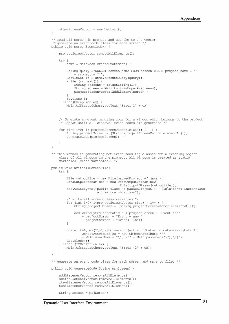
Appendices
Dynamic User Interface Environment 81
otherScreenVector = new Vector();}
/* read all screen in project and set the to the vector * generate an event code class for each screen */public void screenEventCode() {
projectScreenVector.removeAllElements();
try {stmt = Main.con.createStatement();
String query ="SELECT screen_name F ROM screen WHERE project_name = '"+ project + "'";
ResultSet rs = stmt.executeQuery(query);while (rs.next()) {
String screens = rs.getString(1);String screen = Main.ts.trimUnpack(screens);projectScreenVector.addElement(screen);
}rs.close();
} catch(Exception ex) {Main.tfStatusOthers.setText("Error:1" + ex);
}
/* Generate an event handling code for a window which belongs to the project * Repeat until all windows' event codes are generated */
fo r (int i=0; i< projectScreenVector.size(); i++ ) {String projectScreen = (String)projectScreenVector.elementAt(i);generateCode(projectScreen);
}}
/* This method is generating not event handling classes but a creating object class of all windows in the project. All windows is created as static variables (class variables). */
public void writeAllScreenFile() {try {
File outputFile = new File(packedProject +".java");DataOutputStream dos = new DataOutputStream(new
FileOutputStream(outputFile));dos.writeBytes("public class "+ packedProject + " {\n\n\t//to instantiate
all window objects\n");
/* write all screen class variables */ for (int i=0; i<projectScreenVector.size(); i++ ) {
String projectScreen = (String)projectScreenVector.elementAt(i);
dos.writeBytes("\tstatic " + projectScreen + "Event the"+ projectScreen + "Event = new "+ projectScreen + "Event();\n");
}
dos.writeBytes("\n\t//to save object attributes to database\n\tstatic ObjectAttribute oa = new ObjectAttribute(\""+ Main.userName + "\", \"" + Main.password+"\");\n}");
dos.close();} catch (IOException ex) {
Main.tfStatusOthers.setText("Error :2" + ex);}
}
/* generate an event code class for each screen and save to file. */
public void generateCode(String prjScreen) {
addListenerVector.removeAllElements();actionListenerVector.removeAllElements();itemListenerVector.removeAllElements();textListenerVector.removeAllElements();
String screen = prjScreen;
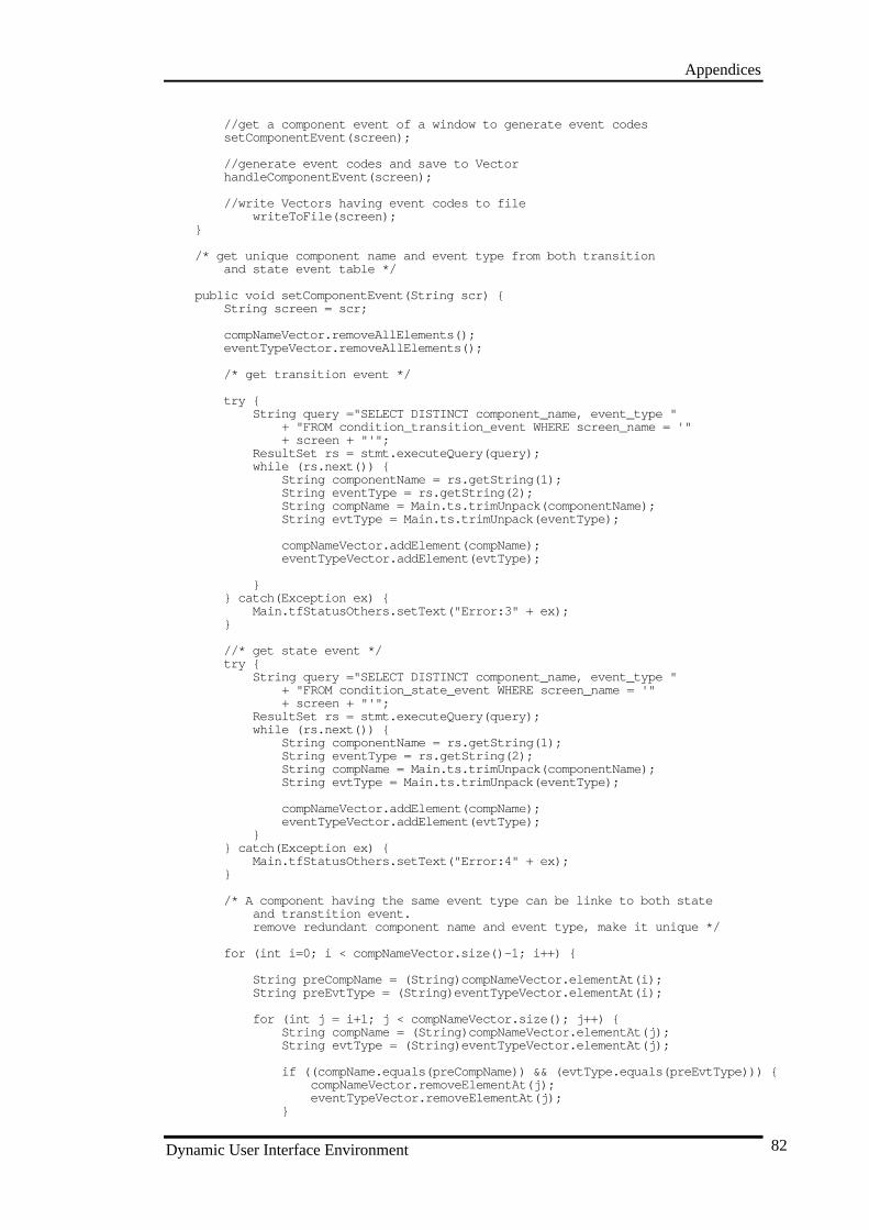
Appendices
Dynamic User Interface Environment 82
//get a component event of a window to generate event codessetComponentEvent(screen);
//generate event codes and save to VectorhandleComponentEvent(screen);
//write Vectors having event codes to file writeToFile(screen);
}
/* get unique component name and event type from both transitionand state event table */
public void setComponentEvent(String s cr) {String screen = scr;
compNameVector.removeAllElements();eventTypeVector.removeAllElements();
/* get transition event */
try {String query ="SELECT DISTINCT component_name, event_type "
+ "FROM condition_transition_event WHERE screen_name = '"+ screen + "'";
ResultSet rs = stmt.executeQuery(query);while (rs.next()) {
String componentName = rs.getString(1);String eventType = rs.getString(2);String compName = Main.ts.trimUnpack(componentName);St ring evtType = Main.ts.trimUnpack(eventType);
compNameVector.addElement(compName);eventTypeVector.addElement(evtType);
}} catch(Exception ex) {
Main.tfStatusOthers.setText("Error:3" + ex);}
//* get state event */try {
String query ="SELECT DISTINCT component_name, event_type "+ "FROM condition_state_event WHERE screen_name = '"+ screen + "'";
ResultSet rs = stmt.executeQuery(query);while (rs.next()) {
String componentName = rs.getString(1);String eventType = rs.getString(2);String compName = Main.ts.trimUnpack(componentName);String evtType = Main.ts.trimUnpack(eventType);
compNameVector.addElement(compName);eventTypeVector.addElement(evtType);
}} catch(Exception ex) {
Main.tfStatusOthers.setText("Error:4" + ex);}
/* A component having the same event type can be linke to both stateand transtition event.remove redundant component name and event type, make it unique */
for (int i=0; i < com pNameVector.size()-1; i++) {
String preCompName = (String)compNameVector.elementAt(i);String preEvtType = (String)eventTypeVector.elementAt(i);
for (int j = i+1; j < compNameVector.size(); j++) {String compName = (String)compNameVector.elementAt(j);String evtType = (String)eventTypeVector.elementAt(j);
if ((compName.equals(preCompName)) && (evtType.equals(preEvtType))) {compNameVector.removeElementAt(j);eventTypeVector.removeElementAt(j);
}
Appendices
Dynamic User Interface Environment 83
}}
}
/* generate event codes for a component event type */public void handleComponentEvent(String scr) {
String screen = scr;
for (int i=0; i< compNameVector.size(); i++) {String compName = (String)compNameVector.elementAt(i);String evtType = (String)eventTypeVector.elementAt(i);/* read transition condition and action, * set transition next screen to the show vector, * set transition component name and attribute, * object name and attribute to the vector */
hand leTransitionEvent(compName, evtType, screen);
/* read condition_transition_event table, * and get unique transition (to remove redundancy for the * case that several conditions of one transition are linked * to the same event), get from/to state of the transition, * remove existing redundancy again (for the case one state has several * transitions), get from/to state action, * get the screen of from/to state action, read action_state_attribute, * and get component attr ibute and name of the from/to state action, * get object name and attribute of the component attribute and name */ handleFromToStateEvent(compName, evtType, screen);
/* get state event condition and action, * get state action screen (show), * get component name & attribute of state action, * object name & attribute */
handleStateEvent(compName, evtType, screen);
/* read all generate code vectors for event, and write them to the suitable listener or shell */
handleEventListener(compName, evtType, screen);}
}
public void handleTransitionEvent(String cName, String eType, String scr) {
String compName = cName;String evtType = eType;String screen = scr;
/* vector initialisation */
// researve condition of transition eventconditionVector.removeAllElements();transitionVector.removeAllElements();classVector.removeAllElements();
// researve transition action for the conditionactionVector.removeAllElements();action TSVector.removeAllElements(); //both transition and state are researvedactionClassVector.removeAllElements();
// researve next screen to generate code --> show screenshowNextScreenVector.removeAllElements();
/* researve transition component attribute and name to generate code --> get component text */
transitionCompAttributeVector.removeAllElements();transitionCompNameVector.removeAllElements();
/* read condition transition event table */
try {String query ="SELECT condition_name, transition_name, class_name "
+ "FROM condition_transition_event WHERE component_name = '"+ compName + "' AND event_type ='" + evtType + "' and screen_name = '"+ screen + "'";
Appendices
Dynamic User Interface Environment 84
ResultSet rs = stmt.executeQuery(query);while (rs.next()) {
String conditionName = rs.getString(1);String transitionName = rs.getString(2);String classNames = rs.getString(3);
String condition = Main.ts.trimUnpack(conditionName);String transition = Main.ts.trimU npack(transitionName);String className = Main.ts.trimUnpack(classNames);
conditionVector.addElement(condition);transitionVector.addElement(transition);classVector.addElement(className);
}rs.close();
} catch(Exception ex) {Main.tfStatusOthers.setText("Error5: " + ex);
}
for (int i=0; i < conditionVector.size(); i++) {String condition = (String)conditionVector.elementAt(i);String transition = (String)transitionVector.elementAt(i);String className = (String)classVector.elementAt(i);
// read action(s) for each conditiongetTransitionAction(condition, transition, className);
}
/* if more than one condition liked to the same event have the same action, * this cause redundant work such as showing the same screen twice or * get the same content of component attribute twice. So, need to remove
redundancy */removeActionRedundancy();
for (int i=0; i < actionVector.size(); i++) {String action = (String)actionVector.el ementAt(i);String actionTransition = (String)actionTSVector.elementAt(i);String actionClass = (String)actionClassVector.elementAt(i);
// get the next screen liked to the transition action,// this screen should be shown when event happensgetTransitionActionScreen(action, actionTransition, actionClass);
// action also causes the change of component AttributegetTransitionComponentAttribute(action, actionTransition, actionClass,
screen);
}}
/* read transitio n activity table and get transition action(s) for a condition */
public void getTransitionAction(String cdn, String trnsn, String cls) {
String condition = cdn;String transition = trnsn;String className = cls;
try {String query ="SELECT action FROM transition_activity where class_name =
'" className + "' and transition_name = '" + transition+ "' and condition = '" + condition + "'";
ResultSet rs = stmt.executeQuery(query);while (rs.next()) {
String actionName = r s.getString(1);String action = Main.ts.trimUnpack(actionName);actionVector.addElement(action);
// this vector reserves both transition and state to use one // removeActionRedundancy methodactionTSVector.addElement(transition);actionClassVector.addElement(className);
}
Appendices
Dynamic User Interface Environment 85
rs.close();} catch(Exception ex) {
Main.tfStatusOthers.setText("Error:6" + ex);}
}
public void removeActionRedundancy() {for (int i=0; i < actionVector.size()-1; i++) {
Stri ng preAction = (String)actionVector.elementAt(i);String preActionTS = (String)actionTSVector.elementAt(i);String preActionClass= (String)actionClassVector.elementAt(i);
for (int j = i+1; j < actionVector.size(); j++) {String curAction = (String)actionVector.elementAt(j);String curActionTS= (String)actionTSVector.elementAt(j);String curActionClass= (String)actionClassVector.elementAt(j);
if ( (curAction.equals(preAction)) &&(curActionTS.equals(preActionTS))
&& (cur ActionClass.equals(preActionClass)) ) {
actionVector.removeElementAt(j);actionTSVector.removeElementAt(j);actionClassVector.removeElementAt(j);
}}
}}
/* find transition action screen, and set it to the showNextScreenVector */
public void getTransitionActionScreen(String act, String trnsn, String cls) {
String action = act;String transition = trnsn;String className = cls;
try {String query = "SELECT screen_name FROM action_transition_screen WHERE
action_name = '"+ action + "' and transition_name = '" + transition + "' and
class_name = '"+ className + "'";
ResultSet rs = stmt.executeQuery(query);while (rs.next()) {
String nextScreenName = rs.getString(1);String nextScreen = Main.ts.trimUnpack(nextScreenName);showNextScreenVector.addElement(nextScreen);
}rs.close();
} catch(Exception ex) {Main.tfStatusOthers.setText("Error7:" + ex);
}
}
public void getTransitionComponentAttribute(String act , String tran, String cls,String scr) {
String action = act;String transition = tran;String className = cls;String screen = scr;
try {String query = "SELECT component_attribute, component_name "
+ "FROM action_transition_attribute WHERE action_name = '"+ action + "' and transition_name = '" + transition+ "' and class_name = '"+ className+ "' and screen_name = '" + screen + "'";
ResultSet rs = stmt.executeQuery(query);while (rs.next()) {
String componen tAttribute = rs.getString(1);String componentName = rs.getString(2);
Appendices
Dynamic User Interface Environment 86
String compAttribute = Main.ts.trimUnpack(componentAttribute);String compName = Main.ts.trimUnpack(componentName);
transitionCompAttributeVector.addElement(compAttribute);transitionCompNameVector.addElement(compName);
}rs.close();
} catch(Exception ex) {Main.tfStatusOthers.setText("Error8:" + ex);
}
}
//to avoid same state is read more than one because of more than one conditon o fsame transition
public void handleFromToStateEvent(String cName, String eType, String scr) {
String compName = cName;String evtType = eType;String screen = scr;
//researve unique condition and class of the compoennt event, this vector usedfor handleTransitionEvent as well
transitionVector.removeAllElements();classVector.removeAllElements();
//transition has only one from state and to statefromStateVector.removeAllElements();toStateVector.removeAllElements();
//to fi nd from/to state action and remove redundancyfromStateClassVector.removeAllElements();toStateClassVector.removeAllElements();
// researve from state action to find from state action exit screenfromActionVector.removeAllElements();fromActionStateVector.removeAllElements();fromActionClassVector.removeAllElements();
// researve to state action to find to state action entry screentoActionVector.removeAllElements();toActionStateVector.removeAllElements();toActionClassVector.re moveAllElements();
//researve exit screen ----> disposefromStateScreenVector.removeAllElements();
//researve entry screen --> showtoStateScreenVector.removeAllElements();
//researve component name and attribute of from/to state
FTCompNameVector.removeAllElements();FTCompAttributeVector.removeAllElements();
try {String query = "SELECT DISTINCT transition_name, class_name "
+ "FROM condition_transition_event WHERE event_type = '"+ evtType + "' and component_ name = '" + compName + "' and screen_name
='"+ screen + "'";
ResultSet rs = stmt.executeQuery(query);while (rs.next()) {
String transitionName = rs.getString(1);String className = rs.getString(2);String transition = Main.ts.trimUnpack(transitionName);String clsName = Main.ts.trimUnpack(className);transitionVector.addElement(transition);classVector.addElement(clsName);
}rs.close();
} catch(Exception ex) {Main.tfStatusOthers.setText("Error9:" + ex);
}
Appendices
Dynamic User Interface Environment 87
for (int i=0; i< transitionVector.size(); i++ ) {String transition = (String)transitionVector.elementAt(i);String className = (String)classVector.elementAt(i);
getFromToState(transition, className);}
/* even though the transition has only one from and to state, * there is still redundant cases. * For example, two transitions may be linked to the same state, * or one state has several transitions. * So, states could be redundant again, need to remove this */
removeFromStateRedundancy();removeToStateRedundancy();
for(int i=0; i< fromStateVector.size(); i++) {String fromState = (String)fromStateVector.elementAt(i);String fromStateClass = (String)fromStateClassVector.elementAt(i);getFromStateAction(fromState, fromStateClass);
}
for(int i=0; i< toStateVector.size(); i++) {String toState = (String)toStateVector.elementAt(i);String toStateClass = (String)toStateClassVector.elementAt(i);getToStateAction(toState, toStateClass);
}
for (int i=0; i < fromActionVector.size(); i++) {
String fromAction = (String)fromActionVector.elementAt(i);String fromActionState = (String)fromActionStateVector.elementAt(i);String fromActionClass = (String)fromActionClassVector.elementAt(i);
// get from state action screengetFromStateScreen(fromAction, fromActionState, fromActionClass);
//get the component attibute of from state actiongetFTStateComponentAttribute(fromAction, fromActionState, fromActionClass,
screen);}
for (int i=0; i < toActionVector.size(); i++) {
String toAction = (String)toActionVector.elementAt(i);String toActionState = (String)toActionStateVector.elementAt(i);String toActionClass = (String)toActionClassVector.elementAt(i);
//get to state action screengetToStateScreen(toAction, toActionState, toActionClass);
//get the component attribute of to state actiongetFTStateComponentAttribute(toAction, toActionState, toActionClass,
screen);}
}
public void getFromToState(String trnsn, String cls) {
String transition = trnsn;String className = cls;
try {String query = "SELECT from_state, to_state FROM transition WHERE
class_name = '"+ className + "' and transition_name = '" + transition + "'";
ResultSet rs = stmt.executeQuery(query);while (rs.next()) {
String fromStateName = rs.getString(1);String toStateName = rs.getString(2);
String fromState = Main.ts.trimUnpack(fromStateName);String toState = Mai n.ts.trimUnpack(toStateName);
fromStateVector.addElement(fromState);toStateVector.addElement(toState);
Appendices
Dynamic User Interface Environment 88
//need to keep class name to find state action, and remove redundancyfromStateClassVector.addElement(className);toStateClassVector.addElement(className);
}rs.close();
} catch(Exception ex) {Main.tfStatusOthers.setText("Error10:" + ex);
}}
//remove the redundant data of fromStatepublic void removeFromStateRedundancy() {
for(int i=0; i< fromStateVecto r.size()-1; i++) {String preFromState = (String)fromStateVector.elementAt(i);String preFromStateClass = (String)fromStateClassVector.elementAt(i);
for (int j = i+1; j < fromStateVector.size(); j++) {String curFromState = (String)fromStateVector.elementAt(j);String curFromStateClass = (String)fromStateClassVector.elementAt(j);
if ( (curFromState.equals(preFromState)) &&(curFromStateClass.equals(preFromStateClass)) ) {
fromStateVector.removeElementAt(j);fromStateC lassVector.removeElementAt(j);
}}
}}
//remove the redundant data of toStatepublic void removeToStateRedundancy() {
for(int i=0; i< toStateVector.size()-1; i++) {String preToState = (String)toStateVector.elementAt(i);String preToStateClass = (String)toStateClassVector.elementAt(i);
for (int j = i+1; j < toStateVector.size(); j++) {String curToState = (String)toStateVector.elementAt(j);String curToStateClass = (String)toStateClassVector.elementAt(j);
if ( (curToState.equals(preToState)) &&(curToStateClass.equals(preToStateClass)) ) {
toStateVector.removeElementAt(j);toStateClassVector.removeElementAt(j);
}}
}}
public void getFromStateAction(String fState, String cls) {String fromState = fState;String className = cls;
try {String query = "SELECT action FROM state_activity WHERE condition = 'exit'
AND state_name = '"+ fromState + "' AND class_name = '" + className + "'";
ResultSet rs = stmt.executeQuery( query);while (rs.next()) {
String stateAction = rs.getString(1);String fromStateAction = Main.ts.trimUnpack(stateAction);fromActionVector.addElement(fromStateAction);
//researve from state and class name to find exit screenfromActionStateVector.addElement(fromState);fromActionClassVector.addElement(className);
}rs.close();
} catch(Exception ex) {Main.tfStatusOthers.setText("Error11:" + ex);
}}
public void getToStateAction(String tState, Strin g cls) {String toState = tState;String className = cls;
Appendices
Dynamic User Interface Environment 89
try {String query = "SELECT action FROM state_activity WHERE condition =
'entry' and state_name = '"+ toState + "' AND class_name = '" + className + "'";
ResultSet rs = stmt.executeQuery(query);while (rs.next()) {
String stateAction = rs.getString(1);String toStateAction = Main.ts.trimUnpack(stateAction);toActionVector.addElement(toStateAction);
//researve from state and class name to find exit scr eentoActionStateVector.addElement(toState);toActionClassVector.addElement(className);
}rs.close();
} catch(Exception ex) {Main.tfStatusOthers.setText("Error12:" + ex);
}}
public void getFromStateScreen(String fAction, String fState, String fCls) {
String action = fAction;String state = fState;String className = fCls;
try {String query = "SELECT screen_name FROM action_state_screen WHERE
action_name = '"+ action + "' AND state_name = '" + state + "' and class_name = '"+ className + "'";
ResultSet rs = stmt.executeQuery(query);while (rs.next()) {
String screen = rs.getString(1);String fromStateScreen = Main.ts.trimUnpack(screen);fromStateScreenVector.addElement(fromStateScreen);
}rs.close();
} catch(Exception ex) {Main.tfStatusOthers.setText("Error113:" + ex);
}}
public void getToStateScreen(String tsAction, String tState, String cls) {String toStateAction = tsAction;String toState = tState;String className = cls;
try {String query = "SELECT screen_name FROM action_state_screen WHERE
action_name = '"+ toStateAction + "' AND state_name = '" + toState + "' and class_name
= '"+ className + "'";
ResultSet rs = stmt.executeQuery(query);while (rs.next()) {
String screen = rs.getString(1);String toStateScreen = Main.ts.trimUnpack(screen);toStateScreenVector.addElement(toStateScreen);
}rs.close();
} catch(Exception ex) {Main.tfStatusOthers.setText("Err or14:" + ex);
}}
//this method is used to find component name and attribute for both from state andto state
public void getFTStateComponentAttribute(String act, String sta, String cls,String scr) {
String action = act;String state =sta;String className = cls;
Appendices
Dynamic User Interface Environment 90
String screen = scr;
try {String query = "SELECT component_attribute, component_name FROM
action_state_attribute WHERE action_name = '"+ action + "' AND state_name = '" + state + "' AND class_name = '"+
className+ "' AND screen_name = '" + screen + "'";
ResultSet rs = stmt.executeQuery(query);while (rs.next()) {
String componentAttribute = rs.getString(1);String componentName = rs.getString(2);
String compAttribute = Main.ts.trimUnpack(componentAttribute);String compName = Main.ts.trimUnpack(componentName);
FTCompAttributeVector.addElement(compAttribute);FTCompNameVector.addElement(compName);
}rs.close();
} catch(Exception ex) {Main.tfStatusOthers.se tText("Error:15" + ex);
}}
public void handleStateEvent(String cName, String eType, String scr) {
String compName = cName;String evtType = eType;String screen = scr;
//researve state condition, reusing but cleaned condition and class vectorconditionVector.removeAllElements();stateVector.removeAllElements();classVector.removeAllElements();
//researve state action, reusing vectors, but cleanedactionVector.removeAllElements();actionTSVector.removeAllElements();acti onClassVector.removeAllElements();
//researve state action screen --> showshowStateScreenVector.removeAllElements();
//researve component name and attributestateCompAttributeVector.removeAllElements();stateCompNameVector.removeAllElements();try {
String query ="SELECT condition_name, state_name, class_name FROMcondition_state_event "
+ "WHERE component_name = '" + compName + "' and event_type ='" +evtType
+ "' and screen_name = '" + screen + "' and condition_name != 'entr y'and condition_name != 'exit'";
ResultSet rs = stmt.executeQuery(query);while (rs.next()) {
String conditionName = rs.getString(1);String stateName = rs.getString(2);String classNames = rs.getString(3);
String condition = Main.ts.trimUnpack(conditionName);String state = Main.ts.trimUnpack(stateName);String className = Main.ts.trimUnpack(classNames);
conditionVector.addElement(condition);stateVector.addElement(state);classVector.addElement(c lassName);
}rs.close();
} catch(Exception ex) {Main.tfStatusOthers.setText("Error16: " + ex);
}
Appendices
Dynamic User Interface Environment 91
for (int i=0; i< conditionVector.size(); i++) {String condition = (String)conditionVector.elementAt(i);String state = (String)stateVector.elementAt(i);String className = (String)classVector.elementAt(i);getStateAction(condition, state, className);
}
// if two state conditions of the same event has same action name, it isredundant.
removeActionRedundancy();
for (int i=0; i < actionVector.size(); i++) {String action = (String)actionVector.elementAt(i);String actionState = (String)actionTSVector.elementAt(i);String actionClass = (String)actionClassVector.elementAt(i);getStateActionScreen(action, actionState, actionClass);
//action causes the change of component AttributegetStateComponentAttribute(action, actionState, actionClass, screen);
}}
public void getStateAction(String cdn, String sta, String cls) {String condition = cdn;String state = sta;String className = cls;try {
String query ="SELECT action FROM state_activity WHERE class_name = '" +className
+ "' AND state_name = '" + state + "' AND condition = '"+ condition + "'";
ResultSet rs = stmt.executeQuery(query);while (rs.next()) {
String actionName = rs.getString(1);String action = Main.ts.trimUnpack(actionName);
//use same vector name to reuse removeRedundancy methodactionVector.addElement(action);actionTSVe ctor.addElement(state);actionClassVector.addElement(className);
}rs.close();
} catch(Exception ex) {Main.tfStatusOthers.setText("Error17:" + ex);
}}
public void getStateActionScreen(String act, String sta, String cls) {String action = act;String state = sta;String className = cls;
try {String query = "SELECT screen_name FROM action_state_screen WHERE
action_name = '"+ action + "' AND state_name = '" + state + "' AND class_name = '"+ className + "'";
ResultSet rs = stmt.executeQuery(query);while (rs.next()) {
String nextScreenName = rs.getString(1);String nextScreen = Main.ts.trimUnpack(nextScreenName);showStateScreenVector.addElement(nextScreen);
}rs.close();
} catch(Exception ex) {Main.tfStatusOthers.setText("Error:18" + ex);
}}
public void getStateComponentAttribute(String act, String sta, String cls, Stringscr) {
String action = act;String state =sta;String className = cls;String screen = scr;
try {
Appendices
Dynamic User Interface Environment 92
String query = "SELECT component_attribute, component_name FROMaction_state_attribute "
+ "WHERE action_name = '" + action + "' and state_name = '" + state+ "' and class_name = '"+ className+ "' and screen_name = '" + screen + "'";
ResultSet rs = stmt.executeQuery(query);while (rs.next()) {
String componentAttribute = rs.getString(1);String componentName = rs.getString(2);
String compAttribute = Main.ts.trimUnpack(componentAttribute);String compName = Main.ts.trimUnpack(componentName);stateCompAttributeVector.addElement(compAttribute);stateCompNameVector.addElement(compName);
}rs.close();
} catch(Exception ex) {Main.tfStatusOthers.setText("Error19:" + ex);
}}
//get all vectors and write to the listener
public void handleEventListener(String cName, String eType, String scr) {
String compName = cName;String evtType = eType;String screen = scr;
String compType = getComponentType(compName, screen);int e ventListener = identifyEventListener(compType, evtType);
setToAddListenerShell(compName, eventListener);setToEventListener(compName, eventListener, compType, screen);
}
public String getComponentType(String cName, String scr) {
String compName = cName;String screen = scr;String compType = "";
try {String query = "SELECT component_type FROM component WHERE component_name
= '" + compName+ "' AND screen_name = '" + screen + "'";
ResultSet rs = stmt.executeQuery(query);while (rs.next()) {
String componentType = rs.getString(1);compType = Main.ts.trimUnpack(componentType);
}rs.close();
} catch(Exception ex) {Main.tfStatusOthers.setText("Error20: " + ex);
}return compType;
}
public int identifyEventListener(String cType, String eType) {String compType = cType;String event = eType;
int listenerType = 0;
if (compType.equals("Button")) {if(event.equals("onClick")) {
listenerType = ACTIONLISTENER;}
} else if (co mpType.equals("Choice")) {if (event.equals("onClick")) {
listenerType = ITEMLISTENER;}
} else if (compType.equals("Checkbox")) {if (event.equals("onClick")) {
listenerType = ITEMLISTENER;}
} else if (compType.equals("TextField")) {
Appendices
Dynamic User Interface Environment 93
if (event.equals("onEnter")) {listenerType = ACTIONLISTENER;
} else if (event.equals("onChange")) {listenerType = TEXTLISTENER;
}} else if (compType.equals("TextArea")) {
if (event.equals("onChange")) {list enerType = TEXTLISTENER;
} } else if (compType.equals("List")) {
if (event.equals("onClick")) {listenerType = ITEMLISTENER;
} else if (event.equals("onDblClick")) {listenerType = ACTIONLISTENER;
}}return listenerType;
}
/* The shell is for saving add linstsner code such as"btn.addActionListener(this)" */
public void setToAddListenerShell(String cName, int evtListener) {
String compName = cName;switch (evtListener) {
case ACTIONLISTENER : addListen erVector.addElement("\t\t" + compName +".addActionListener(this);\n");
break;case ITEMLISTENER : addListenerVector.addElement("\t\t" + compName +
".addItemListener(this);\n");break;
case TEXTLISTENER : addListenerVector.addElement("\t\t" + compName +".addTextListener(this);\n");
break;default : Main.tfStatusOthers.setText("No event listener.");
}}
public void setToEventListener(String cName, int evtListener, String cType, Stringscr) {
String compType = cType;String compName = cName;String screen = scr;int eventListener = evtListener;
String codeBegin = "\n\n\t\tif (source == " + compName + ") {\n";String codeEnd = "\n\t\t}";
switch (eventListener) {case ACTIONLISTENER : actionListenerVector.addElement(codeBegin);
//set transition action screen to ActionListsner --> showString actionNextScreenCode = getShowNextScreenCode();actionListenerVector.addElement(actionNextScreenCode);
//set fromState exit screen to A ctionListsner --> disposeString actionDisposeScreenCode = getFromStateScreenCode();actionListenerVector.addElement(actionDisposeScreenCode);
//set toState entry screen to ActionListsner --> showString actionEntryScreenCode = getToStateScreenCode();actionListenerVector.addElement(actionEntryScreenCode);
//set state screen to ActionListsner and allScreenShell --> showString actionStateScreenCode = getStateScreenCode();actionListenerVector.addElement(actionSta teScreenCode);
//handle transition component name & attribute --> get/save/set textString actionTransitionAttributeCode = getTransitionAttributeCode(
screen);actionListenerVector.addElement(actionTransitionAttributeCode);
Appendices
Dynamic User Interface Environment 94
//handle from/to state component name & attribute --> get/save/settext
String actionFromToStateAttributeCode =getFromToStateAttributeCode(screen);
actionListenerVector.addElement(actionFromToStateAttributeCode);
//handle state co mponent name & attribute --> get/save/set textString actionStateAttributeCode = getStateAttributeCode(screen);actionListenerVector.addElement(actionStateAttributeCode);actionListenerVector.addElement(codeEnd);break;
case ITEMLISTENER : itemListenerVector.addElement(codeBegin);//set transition action screen to ActionListsner --> showString itemNextScreenCode = getShowNextScreenCode();itemListenerVector.addElement(itemNextScreenCode);
//set fromState exit screen to ActionListsner --> disposeString itemDisposeScreenCode = getFromStateScreenCode();itemListenerVector.addElement(itemDisposeScreenCode);
//set toState entry screen to ActionListsner --> showString itemEntryScreenCode = getToStateScreenCode();itemListenerVector.addElement(itemEntryScreenCode);
//set state screen to ActionListsner and allScreenShell --> showString itemStateScreenCode = getStateScreenCode();itemListenerVector.addElement(itemStateScre enCode);
//handle transition component name & attribute --> get/save/set textString itemTransitionAttributeCode = getTransitionAttributeCode(
screen);itemListenerVector.addElement(itemTransitionAttributeCode);
//handle from/to state component name & attribute --> get/save/settext
String itemFromToStateAttributeCode = getFromToStateAttributeCode(screen);
itemListenerVector.addElement(itemFromToStateAttributeCode);
//handle state component name & attribute --> get/save/set textString itemStateAttributeCode = getStateAttributeCode( screen);itemListenerVector.addElement(itemStateAttributeCode);
itemListenerVector.addElement(codeEnd);break;
case TEXTLISTENER : textListenerVector.addElement(codeBegin);//set transition action screen to ActionListsner --> showString textNextScreenCode = getShowNextScreenCode();textListenerVector.addElement(textNextScreenCode);
//set fromState exit screen to Acti onListsner --> disposeString textDisposeScreenCode = getFromStateScreenCode();textListenerVector.addElement(textDisposeScreenCode);
//set toState entry screen to ActionListsner --> showString textEntryScreenCode = getToStateScreenCode();textListenerVector.addElement(textEntryScreenCode);
//set state screen to ActionListsner and allScreenShell --> showString textStateScreenCode = getStateScreenCode();textListenerVector.addElement(textStateScreenCode);
//handle transition component name & attribute --> get/save/set textString textTransitionAttributeCode = getTransitionAttributeCode(
screen);textListenerVector.addElement(textTransitionAttributeCode);
Appendices
Dynamic User Interface Environment 95
//handle from/to state component name & attribute --> get/save/settext
String textFromToStateAttributeCode = getFromToStateAttributeCode(screen);
textListenerVector.addElement(textFromToStateAttributeCode);
//handle state component name & attribute --> get/save/set textString textStateAttributeCode = getStateAttributeCode(screen);textListenerVector.addElement(textStateAttributeCode);
textListenerVector.addElement(codeEnd);break;
}}
public String getShowNextScreenCode() {String nextScreenCode = "";
for (int i=0; i< showNextScreenVector.size(); i++) {String nextScreen = (String)showNextScreenVector.elementAt(i);String screenCode = "\t\t\t" + packedProject + ".the"+ nextScreen +
"Event.setVisible(true);\n\n";nextScreenCode += screenCode;
}return nextScreenCode;
}
public String getFromStateScreenCode() {String disposeScreenCode = "";for (int i=0; i < fromStateScreenVector.size(); i++) {
String disposeScreen = (String)fromStateScreenVector.elementAt(i);String disposeCode = "\t\t\t" + packedProject + ".the" + disposeScreen +
"Event.setVisible(false);\n\t\t\t"+ packedProject + ".the" + disposeScreen +
"Event.dispose();\n\n\n";disposeScreenCode += disposeCode;
}ret urn disposeScreenCode;
}
public String getToStateScreenCode() {String entryScreenCode ="";
for (int i=0; i < toStateScreenVector.size(); i++) {String entryScreen = (String)toStateScreenVector.elementAt(i);String entryCode = "\t\t\t" + packedProject + ".the"+ entryScreen +
"Event.setVisible(true);\n\n";
entryScreenCode += entryCode;
}return entryScreenCode;
}
public String getStateScreenCode() {String stateScreenCode ="";
for (int i=0; i < showStateScreen Vector.size(); i++) {String stateScreen = (String)showStateScreenVector.elementAt(i);String stateCode = "\t\t\t" + packedProject + ".the"+ stateScreen +
"Event.setVisible(true);\n\n";
stateScreenCode += stateCode;}return stateScreenCode;
}
public String getTransitionAttributeCode( String scr) {String screen = scr;
String getCompAttributeCode ="";String saveCompAttributeCode ="";String allCompAttributeCode = "";
for (int i=0 ; i < transitionCompNameVector.size (); i++) {
Appendices
Dynamic User Interface Environment 96
String compName = (String)transitionCompNameVector.elementAt(i);String compAttribute = (String)transitionCompAttributeVector.elementAt(i);String compType = getComponentType(compName, screen);String getCode = writeGetTextCode(compName, compAttribute, compType);getCompAttributeCode += getCode;
String saveCode = writeSaveTextCode(compName, compAttribute, screen);saveCompAttributeCode += saveCode;
}allCompAttributeCode = getCompAttributeCode + saveCompAttributeCode;return allCompAttributeCode;
}
public String writeGetTextCode(String cName, String cAttribute, String cType) {String compName = cName;String compAttribute = cAttribute;String compType = cType;String getCode ="";
if (compType.equals("TextField")) {if (compAttribute.equals("Text")) {
getCode = "\t\t\tString value" + compName + " = " + compName +".getText();\n\n";
}} else if(compType.equals("TextArea")) {
if (compAttribute.equals("Text")) {getCode = "\t\t\tString value" + compName + " = " + compName +
".getText();\n\n";} else if (compAttribute.equals("AppendText")) {
getCode = "\t\t\tString value" + compName + " = " + compName +".getText();\n\n";
}} else if(compType.equals("List")) {
if (compAttribute.equals("Item")) {getCode = "\t\t\tString value" + compName + " = " + compName +
".getSelectedItem();\n\n";}
} else if(compType.equals("Checkbox")) {if (compAttribute.equals("Label")) {
getCode = "\t\t\tString value" + compName + " = " + compName +".getLabel();\n\n";
}} else if(compType.equals("Choice")) {
if (compAttribute.equals("SetItem")) {getCode = "\t\t\tString value" + compName + " = " + compName +
".getSelectedItem();\n\n";} else if (compAttribute.equals("AddItem")) {
getCode = "\t\t\tString value" + compName + " = " + compName +".getSelectedItem();\n\n";
}} else if(compType.equals("Label")) {
if (compAttribute.equals("Text")) {getCode = "\t\t\tString value" + compName + " = " + compN ame +
".getText();\n\n";}
} else if(compType.equals("Button")) {if (compAttribute.equals("Label")) {
getCode = "\t\t\tString value" + compName + " = " + compName +".getLabel();\n\n";
}}
return getCode;}
public String writeSaveTextCode(String cName, String cAttribute, String scr) {String compName = cName;String compAttribute = cAttribute;String screen = scr;objectNameVector.removeAllElements();objectAttributeVector.removeAllElements();
String saveCompone ntCode = "";String setCompAttributeCode = "";String saveSetCode = "";
try {
Appendices
Dynamic User Interface Environment 97
String query = "SELECT object_name, object_Attribute FROM attribute_linkedWHERE component_attribute ='"
+ compAttribute + "' AND component_name = '" + compName + "' ANDscreen_name = '"
+ screen + "'";ResultSet rs = stmt.executeQuery(query);while (rs.next()) {
String oName = rs.getString(1);String oAttribute = rs.getString(2);String objectName = Main.ts.trimUnpack(oName);String objec tAttribute = Main.ts.trimUnpack(oAttribute);
objectNameVector.addElement(objectName);objectAttributeVector.addElement(objectAttribute);
}rs.close();
} catch(Exception ex) {Main.tfStatusOthers.setText("Error:here" + ex);
}
for (int i=0; i < objectAttributeVector.size(); i++) {String objectName = (String)objectNameVector.elementAt(i);String objectAttribute = (String)objectAttributeVector.elementAt(i);String saveCode = "\t\t\tString objectName" + compName + " = \"" +
objectName+ "\";\n\t\t\tString objectAttribute"+ compName + " = \"" + objectAttribute + "\";\n\t\t\t" + packedProject+".oa.saveValue(value" + compName + ", objectName" + compName+ ", objectAttribute" + compName + ");\n\n";
saveComponentCode += saveCode;String setCode = writeSetTextCode(compName, objectName,
objectAttribute,screen);setCompAttributeCode += setCode;
}saveSetCode = saveComponentCode + setCompAttributeCode;return saveSetCode;
}
//write setCode and set relevant screen to allScreenShellpublic String writeSetTextCode( String cName, String oName, String oAttr, String
scr) {String compName = cName;String objectName = oName;String objectAttribute = oAttr;String screen = scr;
otherCompAttributeVector.removeAllElements();otherCompNameVector.removeAllElements();otherScreenVector.removeAllElements();
String setComponentCode ="";
try {String query = "SELECT component_attribute, component_name, screen_name
FROM attribute_linked WHERE object_name ='"+ objectName + "' and object_attribute = '" + objectAttribute + "'";
ResultSet rs = stmt.executeQuery(query);while (rs.next()) {
String ocAttribute = rs.getString(1);String ocName = rs.getString(2);String oScreen = rs.getString(3);String otherCompAttribute = Main.ts.trimUnpack(ocAttribute);String otherCompName = Main.ts.trimUnpack(ocName);String otherScreen = Main.ts.trimUnpack(oScreen);
otherCompAttributeVector.addElement (otherCompAttribute);otherCompNameVector.addElement(otherCompName);otherScreenVector.addElement(otherScreen);
}rs.close();
} catch(Exception ex) {Main.tfStatusOthers.setText("Error:111" + ex);
}removeAttributeRedundancy(screen);
for (int i=0 ; i< otherCompNameVector.size(); i++) {
Appendices
Dynamic User Interface Environment 98
String otherCompName = (String)otherCompNameVector.elementAt(i);String otherCompAttribute = (String)otherCompAttributeVector.elementAt(i);String otherScreen = (String)otherScreenVector.e lementAt(i);String setCode ="";String otherCompType = getComponentType(otherCompName, otherScreen);
if (otherCompType.equals("TextField")) {if (otherCompAttribute.equals("Text")) {
setCode = "\t\t\t" + packedProject +".the" + otherScreen +"Event."
+ otherCompName + ".setText(value" + compName + ");\n\n";}
} else if(otherCompType.equals("TextArea")) {if (otherCompAttribute.equals("Text")) {
setCode = "\t\t\t" + packedProject + ".the" + otherScreen +"Event."
+ otherCompName + ".setText(value" + compName + ");\n\n";} else if (otherCompAttribute.equals("AppendText")) {
setCode = "\t\t\t" + packedProject + ".the" + otherScreen +"Event."
+ otherCompName + ".appendText(value" + compName + ");\n\n";}
} else if(otherCompType.equals("List")) {if (otherCompAttribute.equals("Item")) {
setCode = "\t\t\t" + packedProject + ".the" + otherScreen +"Event."
+ otherCompName + ".addItem(value" + compName + ");\n\n";}
} else if(otherCompType.equals("Checkbox")) {if (otherCompAttribute.equals("Label")) {
setCode = "\t\t\t" + packedProject + ".the" + otherScreen +"Event."
+ otherCompName + ".setLabel(value" + compName + ");\n\n";}
} else if(otherCompType.equals("Choice")) {if (otherCompAttribute.equals("AddItem")) {
setCode = "\t\t\t" + packedProject + ".the" + otherScreen +"Event."
+ otherCompName + ".addItem(value" + compName + ");\n\n";} else if (otherCompAttribute.equals("SetIte m")) {
setCode = "\t\t\t" + packedProject + ".the" + otherScreen +"Event."
+ otherCompName + ".select(value" + compName + ");\n\n";}
} else if(otherCompType.equals("Label")) {if (otherCompAttribute.equals("Text")) {
setCode = "\t\t\t" + packedProject + ".the" + otherScreen +"Event."
+ otherCompName + ".setText(value" + compName + ");\n\n";}
} else if(otherCompType.equals("Button")) {if (otherCompAttribute.equals("Label")) {
setCode = "\t\t\t" + packedP roject + ".the" + otherScreen +"Event."
+ otherCompName + ".setLabel(value" + compName + ");\n\n";}
}setComponentCode += setCode;
}return setComponentCode;
}
public void removeAttributeRedundancy(String scr) { String screen = scr;
for (int i=0; i < otherCompNameVector.size(); i++) {String otherScreen = (String)otherScreenVector.elementAt(i);
if (otherScreen.equals(screen)) {otherCompNameVector.removeElementAt(i);otherCompAttributeVector.remo veElementAt(i);otherScreenVector.removeElementAt(i);
}}
}
Appendices
Dynamic User Interface Environment 99
public String getFromToStateAttributeCode(String scr) {String screen = scr;
String getCompAttributeCode = "";String saveCompAttributeCode = "";
String allCompAttributeCode = "";
for (int i=0 ; i < FTCompNameVector.size(); i++) {String compName = (String)FTCompNameVector.elementAt(i);String compAttribute = (String)FTCompAttributeVector.elementAt(i);String compType = getComponentType(compName, screen );String getCode = writeGetTextCode(compName, compAttribute, compType);getCompAttributeCode += getCode;
String saveCode = writeSaveTextCode(compName, compAttribute, screen);saveCompAttributeCode += saveCode;
}allCompAttributeCode = getCompAttributeCode + saveCompAttributeCode;return allCompAttributeCode;
}
public String getStateAttributeCode( String scr) {String screen = scr;String getCompAttributeCode = "";String saveCompAttributeCode = "";String allCompAttributeC ode = "";
for (int i=0 ; i < stateCompNameVector.size(); i++) {String compName = (String)stateCompNameVector.elementAt(i);String compAttribute = (String)stateCompAttributeVector.elementAt(i);String compType = getComponentType(compName, screen);String getCode = writeGetTextCode(compName, compAttribute, compType);getCompAttributeCode += getCode;String saveCode = writeSaveTextCode(compName, compAttribute, screen);saveCompAttributeCode += saveCode;
}allCompAttributeCode = getCompAttributeCode + saveCompAttributeCode;return allCompAttributeCode;
}public void writeToFile(String scr) {
String screen = scr;try {
File outputFile = new File(screen +"Event.java");DataOutputStream dos = new DataOutputStream(new
FileOutputStream(outputFile));dos.writeBytes("import java.awt.event.*;\nimport java.awt.*;\n\npublic
class "+ screen + "Event extends " + screen+ " implements ActionListener, ItemListener, TextListener {\n\n");
//write a constructor dos.writeBytes("\n\n\t" + screen + "Event() {\n\n");dos.writeBytes("\n\t\t//to stop
running\n\t\tenableEvents(AWTEvent.WINDOW_EVENT_MASK);\n\n");
//write addListenerfor (int i=0; i < addListenerVector.size(); i++ ) {String add = (String)addListenerVector.elementAt(i);dos.writeBytes(add);
}dos.writeBytes("\n\n\t}\n\n\tpublic void processWindowEvent(WindowEvent e)
{\n\t\t" + "if (e.getID() == WindowEvent.WINDOW_CLOSING){\n\t\t\tsetVisible(false);\n\t\t\t"+ "dispose();\n\t\t\tSystem.exit(0);\n\t\t}\n\t}\n\n");
dos.writeBytes("\n\tpublic void actionPerformed(ActionEvent e) {\n\t\tObjectsource = e.getSource();\n");
//write actionListenerfor (int i=0; i<actionListenerVector.size(); i++) {
String code = (String)actionListenerVector.elementAt(i);dos.writeBytes(code);
}dos.writeBytes("\n\n\t}\n\n\tpublic void itemStateChanged(ItemEvent e)
{\n\t\tObject source = e.getSource();\n");//write itemListenerfor (int i=0; i<itemListenerVector.size(); i ++) {
String code = (String)itemListenerVector.elementAt(i);dos.writeBytes(code);
Appendices
Dynamic User Interface Environment 100
}dos.writeBytes("\n\n\t}\n\n\tpublic void textValueChanged(TextEvent e)
{\n\t\tObject source = e.getSource();\n");
//write textListenerfor (int i=0; i<textListenerVector.size(); i++) {
String code = (String)textListenerVector.elementAt(i);dos.writeBytes(code);
}dos.writeBytes("\n\t}\n\n\tpublic static void main(String[] args) {\n\t\t"
+ screen + "Event the"+ scree n + " = new " + screen + "Event();\n\t\tthe" + screen +
".setVisible(true);\n\n\t}\n\n}");dos.close();
} catch (IOException ex) {Main.tfStatusOthers.setText("Error :117" + ex);
} }
}