Embed Size (px)
Citation preview
JOURNAL OFSOUND ANDVIBRATION
www.elsevier.com/locate/jsvi
Journal of Sound and Vibration 268 (2003) 485–501
Dynamic studies of railtrack sleepers in a track structuresystem
G. Kumaran, Devdas Menon*, K. Krishnan Nair
Department of Civil Engineering, Indian Institute of Technology, Chennai 600 036, India
Received 31 May 2002; accepted 20 November 2002
Abstract
This paper discusses the dynamic response of a typical prestressed concrete railtrack sleeper due towheel–track interaction dynamics, involving wheel and rail imperfections, under various parametricconditions. The interaction dynamics of the vehicle and track is first carried out in the time domain usingMSC/NASTRAN. Using the resulting load time histories on an isolated sleeper, a detailed finite elementmodel of the sleeper is used to analyze its dynamic behaviour. The dynamic amplification factors fordeflection, ballast pressure and bending moments have been evaluated at the critical section (rail-seat andcentre) for various exciting frequencies under different vehicle–track parametric conditions. The resultsprovide a basis for improved and rational design of the sleeper.r 2003 Elsevier Science Ltd. All rights reserved.
1. Introduction
The prestressed concrete monoblock sleeper is well recognized as a vital constituent of themodern railway track structure. Such sleepers were first introduced in 1943 at Cheddington inthe UK on an experimental basis [1–3]. The primary function of the railtrack sleeper is totransmit the wheel load to the ballast medium. In addition to the above, it has additionalfunctions such as maintaining track alignment and gauge, restraining longitudinal and lateralrail movements, and providing strength and stability to track structure. The superiority of theprestressed concrete sleeper, in comparison with other sleepers made of timber, steel, castiron or reinforced concrete, lies in its improved structural performance, in terms of stability,
ARTICLE IN PRESS
*Corresponding author.
E-mail addresses: [email protected] (G. Kumaran), [email protected] (D. Menon),
[email protected] (K. Krishnan Nair).
0022-460X/03/$ - see front matter r 2003 Elsevier Science Ltd. All rights reserved.
doi:10.1016/S0022-460X(02)01581-X
stiffness, strength, improved resistance to fatigue loading and durability [4]. Other major factorsinclude convenience in mass production with high-quality control and relative economy (involvingleast life cycle cost).The present-day design of railtrack sleepers is largely based on simplified analysis using
prescribed equivalent loading and uniformly varying ballast pressure distribution. Generally, thepressure distribution is assumed to be uniform ðpÞ under the rail-seat portions, and in the centralregion, is taken as ap; where a is termed the ‘centre binding coefficient’, having a value less thanunity.These simplified design bases, however, do not account explicitly for the influence of the elastic
properties of sleeper, ballast and subgrade, and the possible effects of non-uniform contact at thesleeper–ballast interface. The prescribed simplified methods of railtrack sleeper design continue tobe based on approximate load modelling and analysis. Such analytical procedures have beenprescribed by the American Railway Engineering Manual (AREMA) and the Research DesignStandards Organisation (RDSO), Indian Railways [1,5].Although considerable research has been done in the area of vehicle–rail interaction in the past,
analysis of the dynamic response of the sleeper in isolation is a problem that has not receivedsufficient attention. The dynamic nature of the loading is not only due to the wheel–trackinteraction, but also due to wheel and rail imperfections [6–10].Analytical studies by the authors have shown that the ballast pressure distributions
obtained from both static and dynamic analyses are highly non-uniform and the criticalsections are obtained at the rail-seat and at the centre of the sleeper [11]. The aim of the presentwork is to assess the prevailing analytical procedures of railtrack sleepers on the basis of morerigorous modelling and analysis, and to make improved recommendations for more rationaldesign.In order to examine the behaviour of sleepers in a railtrack structure, a model involving
all components of the track structure and vehicle parameters is required. In this paper,the response of the railtrack sleeper is investigated in a track structure system, considering thevehicle (axle type), condition of the suspension system, vehicle speed, contact between wheel andrail, wheel and rail defects (irregularities), as well as non-uniform contact between sleeper andballast.Three models are considered for the dynamic analysis of the railtrack sleeper in the track
structure system, viz., ‘vehicle’ model, ‘track’ model and ‘sleeper in isolation’ model. The vehicleand track models are used to determine the rail-seat load history that is transmitted to the sleepersduring the passage of the vehicle, considering different imperfections such as rail corrugations,wheel-flats and rail joints. In the track model, a track length encompassing 12 sleepers isconsidered. The interaction between the vehicle and track is carried out in the time domain usingthe finite element software MSC/NASTRAN. The results from the track structure model are thenused as load time histories on an isolated sleeper model that focuses on the detailed studies of itsdynamic behaviour, in terms of deflection, ballast pressure and bending moment responses. Theresults depict the nature of the non-uniform distribution of ballast pressures and dynamicamplification factors under different exciting frequencies. The stress resultants (peak bendingmoments) are obtained from the rigorous dynamic analysis. The results obtained are used toformulate an equivalent static model to facilitate practical design of railtrack sleepers. Thisprovides a rational basis for improved design recommendations.
ARTICLE IN PRESS
G. Kumaran et al. / Journal of Sound and Vibration 268 (2003) 485–501486
2. Rigorous modelling of vehicle and track structure
2.1. Modelling of vehicle
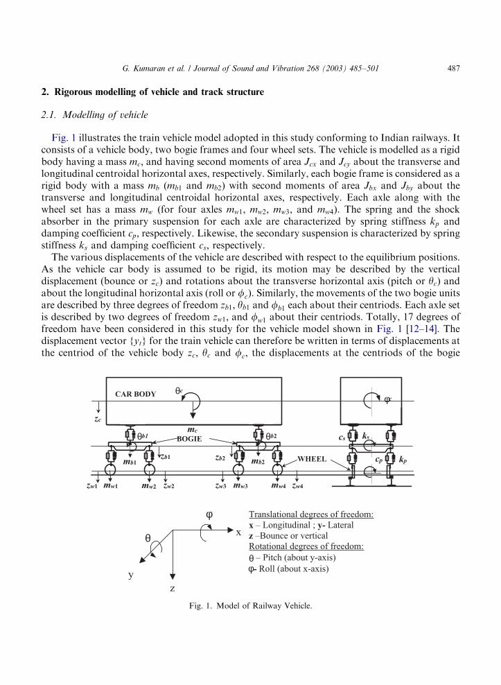
Fig. 1 illustrates the train vehicle model adopted in this study conforming to Indian railways. Itconsists of a vehicle body, two bogie frames and four wheel sets. The vehicle is modelled as a rigidbody having a mass mc; and having second moments of area Jcx and Jcy about the transverse andlongitudinal centroidal horizontal axes, respectively. Similarly, each bogie frame is considered as arigid body with a mass mb (mb1 and mb2) with second moments of area Jbx and Jby about thetransverse and longitudinal centroidal horizontal axes, respectively. Each axle along with thewheel set has a mass mw (for four axles mw1; mw2; mw3; and mw4). The spring and the shockabsorber in the primary suspension for each axle are characterized by spring stiffness kp anddamping coefficient cp; respectively. Likewise, the secondary suspension is characterized by springstiffness ks and damping coefficient cs; respectively.The various displacements of the vehicle are described with respect to the equilibrium positions.
As the vehicle car body is assumed to be rigid, its motion may be described by the verticaldisplacement (bounce or zc) and rotations about the transverse horizontal axis (pitch or yc) andabout the longitudinal horizontal axis (roll or fc). Similarly, the movements of the two bogie unitsare described by three degrees of freedom zb1; yb1 and fb1 each about their centriods. Each axle setis described by two degrees of freedom zw1; and fw1 about their centriods. Totally, 17 degrees offreedom have been considered in this study for the vehicle model shown in Fig. 1 [12–14]. Thedisplacement vector fytg for the train vehicle can therefore be written in terms of displacements atthe centriod of the vehicle body zc; yc and fc; the displacements at the centriods of the bogie
ARTICLE IN PRESS
θc
mc
CAR BODY
BOGIE
WHEEL
φc
ks
kpcp
csθb1 θb2
mb1 mb2
mw1 mw2 mw3 mw4
zb1 zb2
zc
zw1 zw2 zw3 zw4
θ
φ
y
z
x
Translational degrees of freedom:
x – Longitudinal ; y- Lateral
z –Bounce or verticalRotational degrees of freedom:
θ – Pitch (about y-axis)
φ- Roll (about x-axis)
Fig. 1. Model of Railway Vehicle.
G. Kumaran et al. / Journal of Sound and Vibration 268 (2003) 485–501 487
frames zb1; yb1; fb1; zb2; yb2 and fb2; and the displacements of the four axles zw1; fw1; zw2; fw2; zw3;fw3; zw4; and fw4 as
fytg ¼zc; zb1; zb2; zw1; zw2; zw3; zw4; yc; yb1;
yb2;fc;fb1;fb2;fw1;fw2;fw3;fw4
( ): ð1Þ
The reactions at the left and right points on the rails are expressed in terms of the static reactivecomponents WL and WR; respectively, and are given as
WL or WR ¼mcg
4þ
mbg
2þ mwg: ð2Þ
Similarly, the dynamic reactions at the left and right points on the rails are expressed in terms ofthe dynamic reactive components WLðtÞ and WRðtÞ; respectively. Non-linearities in the behaviourof the both primary and secondary suspension units are not considered in the present study.The response is obtained when the vehicle traverses 12 sleeper bays of a model of a railway
track with the constant speed. An initially straight track with imperfections and withoutimperfections is considered. The vertical dynamic response of railtrack sleeper excited undermoving multi-axle loads on track structure is investigated. The wheels of the train are assumed tohave infinite stiffness. It is also assumed that there is no loss of contact between the wheels of thevehicle and the rails. A Digital Power FORTRAN subroutine has been written to performdynamic analysis of the vehicle effectively using direct integration technique. The equation ofmotion for the vehicle model consisting of carbody, bogie units and wheel sets are derived fromrigid-body idealization, and can be expressed as
m.yþ c’yþ ky ¼ WðtÞ; ð3Þ
where m; c and k are the mass, damping and stiffness matrices of the vehicle, respectively, andWðtÞ is the load vector.
2.2. Modelling of track structure
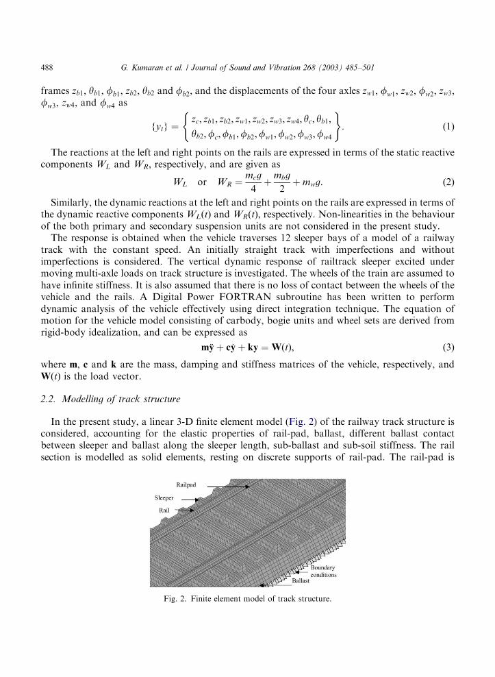
In the present study, a linear 3-D finite element model (Fig. 2) of the railway track structure isconsidered, accounting for the elastic properties of rail-pad, ballast, different ballast contactbetween sleeper and ballast along the sleeper length, sub-ballast and sub-soil stiffness. The railsection is modelled as solid elements, resting on discrete supports of rail-pad. The rail-pad is
ARTICLE IN PRESS
Fig. 2. Finite element model of track structure.
G. Kumaran et al. / Journal of Sound and Vibration 268 (2003) 485–501488
modelled as a spring element, which has vertical stiffness kpad and viscous damping cpad : Thespring behaviour of the rail fastenings with an uplift motion of the rail is not considered in thisstudy. The sleeper, ballast and sub-ballast are modelled as three-dimensional solid elements,accounting for their elastic properties. The contact between the sleeper and the ballast isconsidered along the sleeper length. The substrata are modelled using linear boundary elementsand absorbing boundary conditions. In this study, the absorbing or silent boundary conditionsare imposed at the base of the horizontal ballast of the finite model. The finite boundaries of suchmodel of the soil medium should be such that the elastic waves, which propagate through themedium, do not reflect back from these boundaries to the vibrating medium [15–19]. The length ofthe track considered is limited to 12 sleeper bays, primarily in view of the excessive computationaltime required to solve the 3-D dynamic interaction problem through numerical integration in thetime domain. However, the results of the dynamic analysis show that the track length adopted issufficient to capture the peak response due to the passage of a full train of 12 bogie units atconstant speed.
3. Dynamic analysis of railtrack sleepers in track structure
3.1. Track inputs to railway vehicles
The dynamic wheel loads generated by a moving train are mainly due to various wheel/trackimperfections. These imperfections are considered as the primary source of dynamic track input tothe railroad vehicles. Normally, the imperfections that exist in the railtrack structure areassociated with the vertical track profile, cross level, rail joint, wheel flatness, wheel/rail surfacecorrugations and uneven support of the sleepers.For the present study, the average vertical profile data on left and right rails of a continuously
welded mainline track of the Indian railway are used. These data are obtained from the IndianRailways Research Design and Standards Organisation, Lucknow, based on actual rail trackmeasurements [21]. The average vertical profile data of a continuously welded mainline track ofthe Indian railway have been superimposed on the periodic irregularities (repeated rail joint alongwith wheel flatness) to provide realistic track input to the vehicle model. The initial excitationforces due to the track irregularities applied to the vehicle model are FðtÞ ¼ kpyðtÞ; where yðtÞ isthe average vertical profile of the track. The initial excitation force due to the track irregularitiesare fed to the vehicle system at each primary suspension unit of wheels with time lags of tðl=vÞcorresponding to the distances between two consecutive axles l: These force inputs are repeatedbetween successive time intervals till the complete length of train passes out with constantvelocity v:
3.2. Interaction analysis
The dynamic interaction of combined systems such as vehicle and track needs special attentionwhen the fast moving heavy vehicles interact with the track structure. The objective of theinteraction analysis is to determine the time histories of the wheel load reactions transmitted to the
ARTICLE IN PRESS
G. Kumaran et al. / Journal of Sound and Vibration 268 (2003) 485–501 489
sleeper. These can be expressed as follows (detailed derivation is given in Appendix A):
WLðtÞ ¼mw .zw1 þ 2cp ’zw1 � 2cp ’zb1 þ 2cplb ’yb1 þ 2kpzw1 � 2kpzb1 þ 2kplbyb1 þ 2kwzw1
� Jwx.fw1 þ 2cplg ’fw1lp þ 2cplb ’fb1lp � 2kwfw1l
2g þ 2kplgfw1lp þ 2kplbfb1lp; ð6Þ
WRðtÞ ¼mw .zw1 þ 2cp ’zw1 � 2cp ’zb1 þ 2cplb ’yb1 þ 2kpzw1 � 2kpzb1 þ 2kplbyb1 þ 2kwzw1
þ Jwx.fw1 � 2cplg ’fw1lp � 2cplb ’fb1lp þ 2kwfw1l
2g � 2kplgfw1lp � 2kplbfb1lp; ð7Þ
where WL(t) and WR(t) are the reactions at the left and right rail, respectively. The equation ofmotion for the entire vehicle track structure is written as
mV 0
0 mT
" #.yþ
cV 0
0 cT
" #’yþ
kV 0
0 kT
" #y ¼ WðtÞ; ð8Þ
where mV ; cV and kV are the mass, damping and stiffness matrices of the vehicle system,respectively, and the corresponding parameters with the subscript T refers to the track system.The external force vectorWðtÞ resulting from the wheel loads is dependent on the wheel and track(rail) interaction, and hence is time dependent.The interaction between vehicle and track is solved numerically in time-domain approach. In
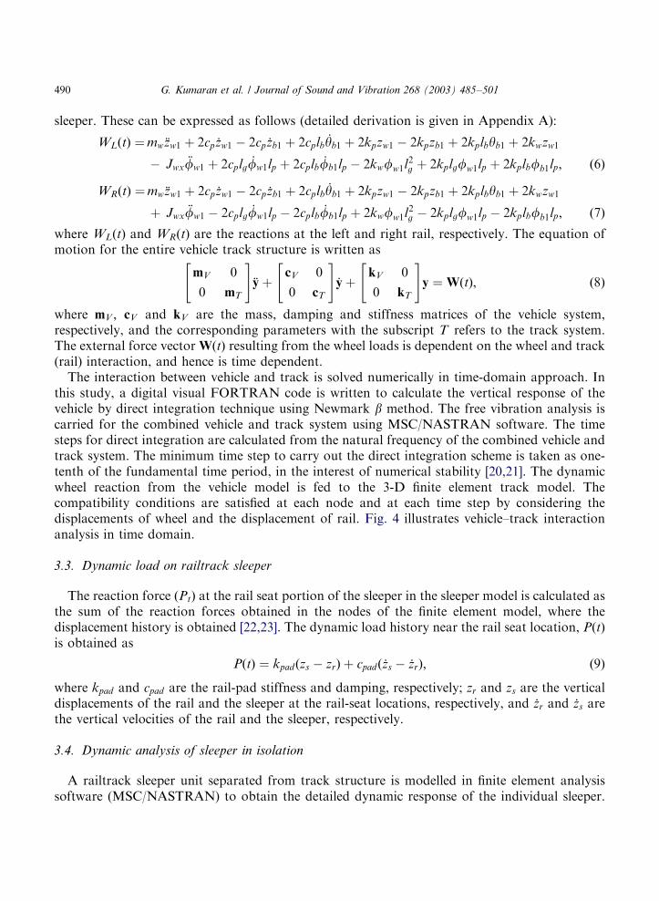
this study, a digital visual FORTRAN code is written to calculate the vertical response of thevehicle by direct integration technique using Newmark b method. The free vibration analysis iscarried for the combined vehicle and track system using MSC/NASTRAN software. The timesteps for direct integration are calculated from the natural frequency of the combined vehicle andtrack system. The minimum time step to carry out the direct integration scheme is taken as one-tenth of the fundamental time period, in the interest of numerical stability [20,21]. The dynamicwheel reaction from the vehicle model is fed to the 3-D finite element track model. Thecompatibility conditions are satisfied at each node and at each time step by considering thedisplacements of wheel and the displacement of rail. Fig. 4 illustrates vehicle–track interactionanalysis in time domain.
3.3. Dynamic load on railtrack sleeper
The reaction force ðPtÞ at the rail seat portion of the sleeper in the sleeper model is calculated asthe sum of the reaction forces obtained in the nodes of the finite element model, where thedisplacement history is obtained [22,23]. The dynamic load history near the rail seat location, PðtÞis obtained as
PðtÞ ¼ kpadðzs � zrÞ þ cpadð’zs � ’zrÞ; ð9Þ
where kpad and cpad are the rail-pad stiffness and damping, respectively; zr and zs are the verticaldisplacements of the rail and the sleeper at the rail-seat locations, respectively, and ’zr and ’zs arethe vertical velocities of the rail and the sleeper, respectively.
3.4. Dynamic analysis of sleeper in isolation
A railtrack sleeper unit separated from track structure is modelled in finite element analysissoftware (MSC/NASTRAN) to obtain the detailed dynamic response of the individual sleeper.
ARTICLE IN PRESS
G. Kumaran et al. / Journal of Sound and Vibration 268 (2003) 485–501490
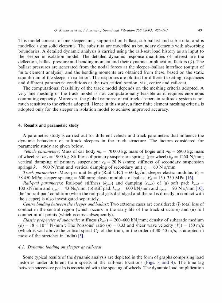
This model consists of one sleeper unit, supported on ballast, sub-ballast and sub-strata, and ismodelled using solid elements. The substrata are modelled as boundary elements with absorbingboundaries. A detailed dynamic analysis is carried using the rail-seat load history as an input tothe sleeper in isolation model. The detailed dynamic response quantities of interest are thedeflection, ballast pressure and bending moment and their dynamic amplification factors ðcÞ: Theballast pressures are generated from the nodal forces at the sleeper–ballast interface (output offinite element analysis), and the bending moments are obtained from these, based on the staticequilibrium of the sleeper in isolation. The responses are plotted for different exciting frequenciesand different parametric conditions at the two critical section, viz., centre and rail-seat.The computational feasibility of the track model depends on the meshing criteria adopted. A
very fine meshing of the track model is not computationally feasible as it requires enormouscomputing capacity. Moreover, the global response of railtrack sleepers in railtrack system is notmuch sensitive to the criteria adopted. Hence in this study, a finer finite element meshing criteria isadopted only for the sleeper in isolation model to achieve improved accuracy.
4. Results and parametric study
A parametric study is carried out for different vehicle and track parameters that influence thedynamic behaviour of railtrack sleepers in the track structure. The factors considered forparametric study are given below.
Vehicle parameters: Mass of car body mc ¼ 70 000 kg; mass of bogie unit mb ¼ 5800 kg; massof wheel-set mw ¼ 1900 kg: Stiffness of primary suspension springs (per wheel) kp ¼ 1260 N=mm;vertical damping of primary suspension: cp ¼ 20 N s=mm; stiffness of secondary suspensionsprings ks ¼ 900 N=mm and vertical damping of secondary unit cp ¼ 60 N s=mm:
Track parameters: Mass per unit length ðRail UICÞ ¼ 60 kg=m; sleeper elastic modulus Ec ¼38 450 MPa; sleeper spacing ¼ 600 mm; elastic modulus of ballast Eb ¼ 150–350 MPa [16].
Rail-pad parameters: Rail-pad stiffness ðkpadÞ and damping ðcpadÞ of (a) soft pad: kpad ¼100 kN=mm and cpad ¼ 43 Ns=mm; (b) stiff pad: kpad ¼ 600 kN=mm and cpad ¼ 93 N s=mm [10];the ‘no rail-pad’ condition (when the rail-pad gets dislodged and the rail is directly in contact withthe sleeper) is also investigated separately.
Centre binding between the sleeper and ballast: Two extreme cases are considered: (i) total loss ofcontact in the central region (which occurs in the early life of the track structure) and (ii) fullcontact at all points (which occurs subsequently).
Elastic properties of subgrade: stiffness ðksubÞ ¼ 200–600 kN=mm; density of subgrade mediumðrÞ ¼ 18� 10�6 N=mm3; The Poissons’ ratio ðZÞ ¼ 0:33 and shear wave velocity ðVsÞ ¼ 150 m=s(which is well above the critical speed CT of the train, in the order of 30–40 m=s; is adopted inmost of the stretches in India) [5].
4.1. Dynamic loading on sleeper at rail-seat
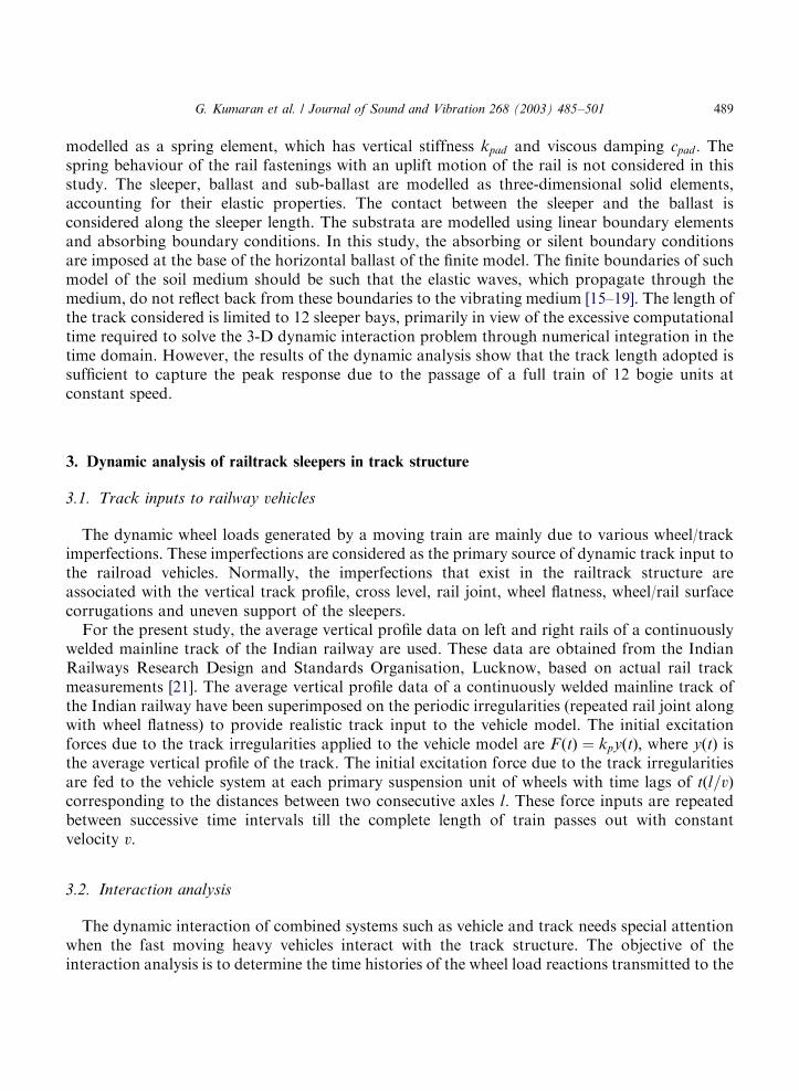
Some typical results of the dynamic analysis are depicted in the form of graphs comprising loadhistories under different train speeds at the rail-seat locations (Figs. 3 and 4). The time lagbetween successive peaks is associated with the spacing of wheels. The dynamic load amplification
ARTICLE IN PRESS
G. Kumaran et al. / Journal of Sound and Vibration 268 (2003) 485–501 491

ARTICLE IN PRESS
0
10000
20000
30000
40000
50000
60000
70000
0 0.5 1 1.5 2 2.5 3 3.5 4 4.5Time in s
For
ce (
in N
) on
lef
t ra
il-s
eat
0
10000
20000
30000
40000
50000
60000
70000
0 0.5 1 1.5 2 2.5 3 3.5 4 4.5Time in s
For
ce (
in N
) on
rig
ht r
ail-
seat
(a)
(b)
Fig. 4. Dynamic load history near the left and right rail-seat areas for Eb ¼ 350MPa; ‘no rail-pad’ condition and
ksub ¼ 600 kN=mm:
Response fromvehicle model
Vehicle dynamics
Vertical vehicledynamics model
Track Input for vehicle modelTrack input to vehicle model
R(t) = kpy(t)
Track FEM Model
Checking the compatibilityconditions at the contactnodes between wheel and
track
If satisfied
Combined vehicle and track responses
Upd
ated
val
ue o
f y(
t)
Load history near the sleepers P(t)
Sleeper response to various train speeds
Not
Sat
isfi
ed
Fig. 3. Flow chart illustrating vehicle-track interaction analysis in time domain.
G. Kumaran et al. / Journal of Sound and Vibration 268 (2003) 485–501492
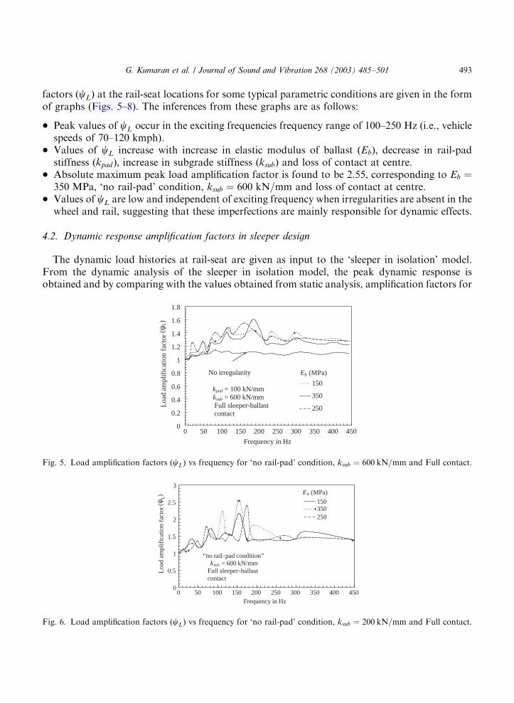
factors ðcLÞ at the rail-seat locations for some typical parametric conditions are given in the formof graphs (Figs. 5–8). The inferences from these graphs are as follows:
* Peak values of cL occur in the exciting frequencies frequency range of 100–250 Hz (i.e., vehiclespeeds of 70–120 kmph).
* Values of cL increase with increase in elastic modulus of ballast ðEbÞ; decrease in rail-padstiffness ðkpadÞ; increase in subgrade stiffness ðksubÞ and loss of contact at centre.
* Absolute maximum peak load amplification factor is found to be 2.55, corresponding to Eb ¼350 MPa; ‘no rail-pad’ condition, ksub ¼ 600 kN=mm and loss of contact at centre.
* Values of cL are low and independent of exciting frequency when irregularities are absent in thewheel and rail, suggesting that these imperfections are mainly responsible for dynamic effects.
4.2. Dynamic response amplification factors in sleeper design
The dynamic load histories at rail-seat are given as input to the ‘sleeper in isolation’ model.From the dynamic analysis of the sleeper in isolation model, the peak dynamic response isobtained and by comparing with the values obtained from static analysis, amplification factors for
ARTICLE IN PRESS
0
0.2
0.4
0.6
0.8
1
1.2
1.4
1.6
1.8
0 50 100 150 200 250 300 350 400 450
Frequency in Hz
Loa
d am
plif
icat
ion
fact
or
150
350
250
kpad = 100 kN/mm ksub = 600 kN/mm
Full sleeper-ballast contact
No irregularity Eb (MPa)
(ψL)
Fig. 5. Load amplification factors (cL) vs frequency for ‘no rail-pad’ condition, ksub ¼ 600 kN=mm and Full contact.
0
0.5
1
1.5
2
2.5
3
0 50 100 150 200 250 300 350 400 450Frequency in Hz
Loa
d am
plif
icat
ion
fact
or
150350250
“no rail-pad condition”ksub = 600 kN/mm
Full sleeper-ballast contact
Eb (MPa)
(ψL)
Fig. 6. Load amplification factors (cL) vs frequency for ‘no rail-pad’ condition, ksub ¼ 200 kN=mm and Full contact.
G. Kumaran et al. / Journal of Sound and Vibration 268 (2003) 485–501 493
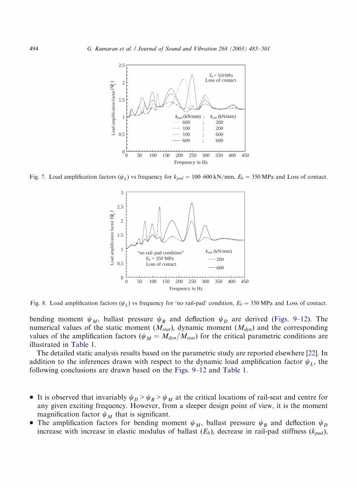
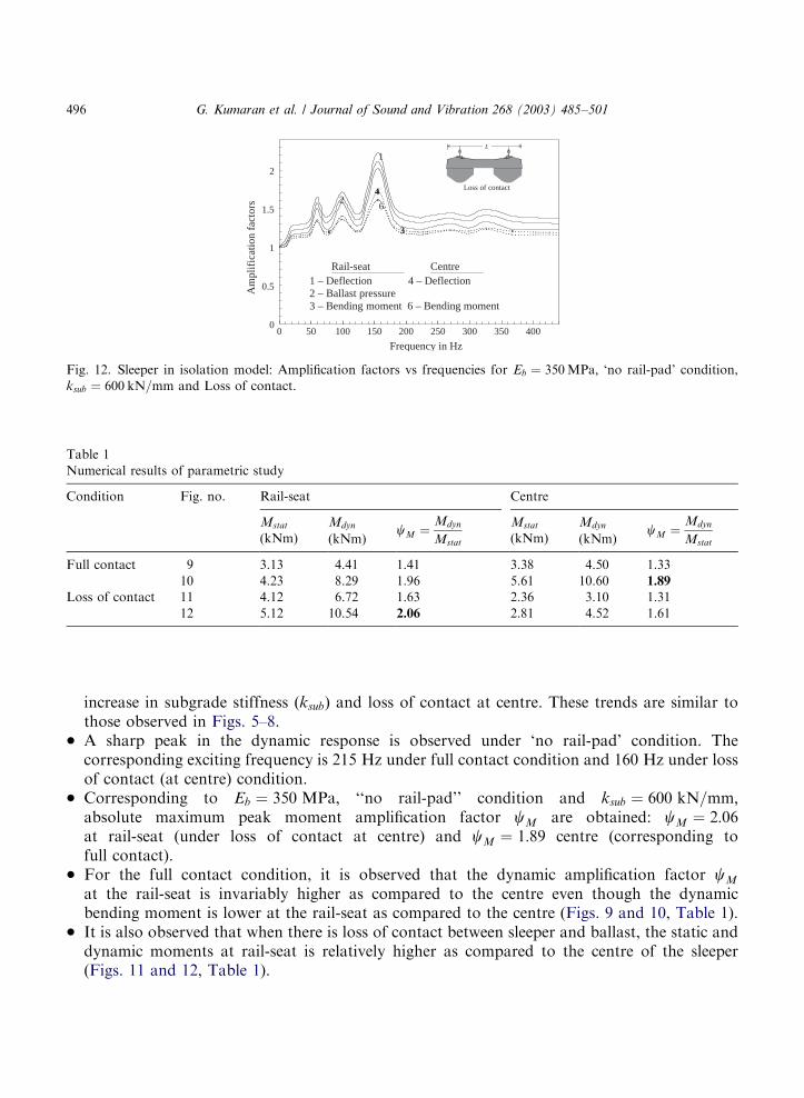
bending moment cM ; ballast pressure cB and deflection cD are derived (Figs. 9–12). Thenumerical values of the static moment ðMstatÞ; dynamic moment ðMdynÞ and the correspondingvalues of the amplification factors ðcM ¼ Mdyn=MstatÞ for the critical parametric conditions areillustrated in Table 1.The detailed static analysis results based on the parametric study are reported elsewhere [22]. In
addition to the inferences drawn with respect to the dynamic load amplification factor cL; thefollowing conclusions are drawn based on the Figs. 9–12 and Table 1.
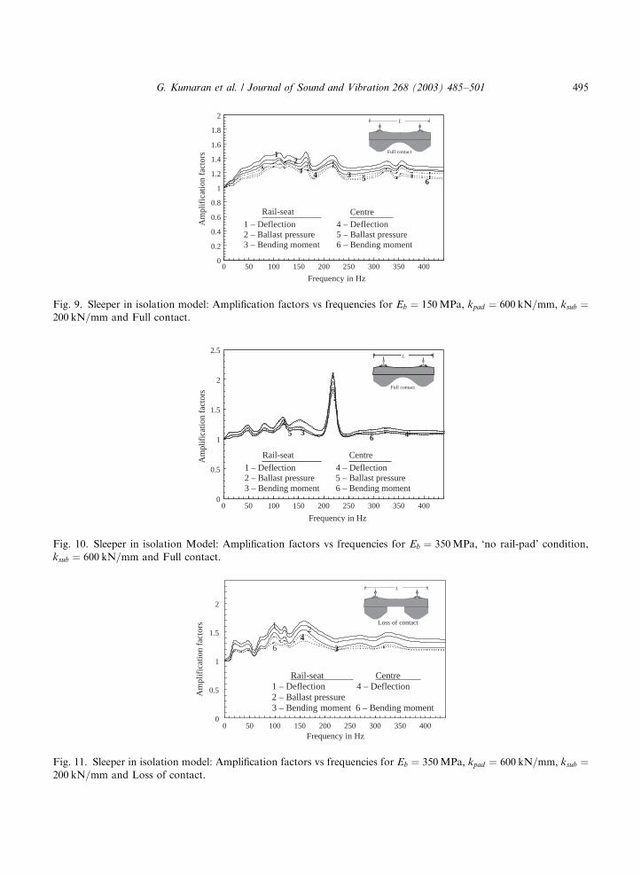
* It is observed that invariably cD > cB > cM at the critical locations of rail-seat and centre forany given exciting frequency. However, from a sleeper design point of view, it is the momentmagnification factor cM that is significant.
* The amplification factors for bending moment cM ; ballast pressure cB and deflection cD
increase with increase in elastic modulus of ballast ðEbÞ; decrease in rail-pad stiffness ðkpadÞ;
ARTICLE IN PRESS
0
0.5
1
1.5
2
2.5
0 50 100 150 200 250 300 350 400 450
Loa
d am
plif
icat
ion
fact
or
600 ; 200 100 ; 200 100 ; 600600 ; 600
Eb = 350 MPa
kpad (kN/mm) ; ksub (kN/mm)(
L)
ψ
Frequency in Hz
Loss of contact
Fig. 7. Load amplification factors (cL) vs frequency for kpad ¼ 100–600 kN=mm; Eb ¼ 350MPa and Loss of contact.
0
0.5
1
1.5
2
2.5
3
0 50 100 150 200 250 300 350 400 450
Frequency in Hz
Loa
d am
plif
icat
ion
fact
or
200
600
ksub (kN/mm) “no rail-pad condition” Eb = 350 MPa
Loss of contact
( ψL)
Fig. 8. Load amplification factors (cL) vs frequency for ‘no rail-pad’ condition, Eb ¼ 350MPa and Loss of contact.
G. Kumaran et al. / Journal of Sound and Vibration 268 (2003) 485–501494
ARTICLE IN PRESS
0
0.2
0.4
0.6
0.8
1
1.2
1.4
1.6
1.8
2
0 50 100 150 200 250 300 350 400
Frequency in Hz
Am
plif
icat
ion
fact
ors 1
3
2
546
Rail-seat Centre
1 – Deflection 4 – Deflection2 – Ballast pressure 5 – Ballast pressure3 – Bending moment 6 – Bending moment
Full contact
L
Fig. 9. Sleeper in isolation model: Amplification factors vs frequencies for Eb ¼ 150MPa; kpad ¼ 600 kN=mm; ksub ¼200 kN=mm and Full contact.
0
0.5
1
1.5
2
2.5
0 50 100 150 200 250 300 350 400
Frequency in Hz
Am
plif
icat
ion
fact
ors
1
32
5 46
Rail-seat Centre
1 – Deflection 4 – Deflection2 – Ballast pressure 5 – Ballast pressure3 – Bending moment 6 – Bending moment
L
Full contact
Fig. 10. Sleeper in isolation Model: Amplification factors vs frequencies for Eb ¼ 350MPa; ‘no rail-pad’ condition,
ksub ¼ 600 kN=mm and Full contact.
0
0.5
1
1.5
2
0 50 100 150 200 250 300 350 400Frequency in Hz
Am
plif
icat
ion
fact
ors 1
34
6
Rail-seat Centre1 – Deflection 4 – Deflection2 – Ballast pressure3 – Bending moment 6 – Bending moment
2
L
Loss of contact
Fig. 11. Sleeper in isolation model: Amplification factors vs frequencies for Eb ¼ 350MPa; kpad ¼ 600 kN=mm; ksub ¼200 kN=mm and Loss of contact.
G. Kumaran et al. / Journal of Sound and Vibration 268 (2003) 485–501 495
increase in subgrade stiffness ðksubÞ and loss of contact at centre. These trends are similar tothose observed in Figs. 5–8.
* A sharp peak in the dynamic response is observed under ‘no rail-pad’ condition. Thecorresponding exciting frequency is 215 Hz under full contact condition and 160 Hz under lossof contact (at centre) condition.
* Corresponding to Eb ¼ 350 MPa; ‘‘no rail-pad’’ condition and ksub ¼ 600 kN=mm;absolute maximum peak moment amplification factor cM are obtained: cM ¼ 2:06at rail-seat (under loss of contact at centre) and cM ¼ 1:89 centre (corresponding tofull contact).
* For the full contact condition, it is observed that the dynamic amplification factor cM
at the rail-seat is invariably higher as compared to the centre even though the dynamicbending moment is lower at the rail-seat as compared to the centre (Figs. 9 and 10, Table 1).
* It is also observed that when there is loss of contact between sleeper and ballast, the static anddynamic moments at rail-seat is relatively higher as compared to the centre of the sleeper(Figs. 11 and 12, Table 1).
ARTICLE IN PRESS
0
0.5
1
1.5
2
0 50 100 150 200 250 300 350 400
Frequency in Hz
Am
plif
icat
ion
fact
ors
1
3
4
6
Rail-seat Centre1 – Deflection 4 – Deflection2 – Ballast pressure3 – Bending moment 6 – Bending moment
L
Loss of contact
2
Fig. 12. Sleeper in isolation model: Amplification factors vs frequencies for Eb ¼ 350MPa; ‘no rail-pad’ condition,
ksub ¼ 600 kN=mm and Loss of contact.
Table 1
Numerical results of parametric study
Condition Fig. no. Rail-seat Centre
Mstat
(kNm)
Mdyn
(kNm)cM ¼
Mdyn
Mstat
Mstat
(kNm)
Mdyn
(kNm)cM ¼
Mdyn
Mstat
Full contact 9 3.13 4.41 1.41 3.38 4.50 1.33
10 4.23 8.29 1.96 5.61 10.60 1.89
Loss of contact 11 4.12 6.72 1.63 2.36 3.10 1.31
12 5.12 10.54 2.06 2.81 4.52 1.61
G. Kumaran et al. / Journal of Sound and Vibration 268 (2003) 485–501496
5. Conclusions
A rigorous mathematical model, including the vehicle (with 17 degrees of freedom) and trackstructure is investigated, considering vehicle suspension system, speed, wheel and rail irregularitiesand elastic properties of the rail-pad and ballast–subgrade. The common imperfections, due torailjoints, wheel flatness and track unevenness, have been considered in the dynamic input to thevehicle model. The damping characteristics of the track and the railway vehicle have also beenconsidered. The effect of the semi-infinite medium of subsoil is considered by imposing silentboundary conditions at the base of the horizontal ballast of the finite model. The elastic propertiesof the equivalent Winkler springs are derived based on the shear wave velocity of the medium. Thedynamic interactive analysis is carried out between the vehicle and track in the time domain usingMSC/NASTRAN finite element software. The results of the interactive analysis give responses inthe form of reaction time histories at the rail-seat locations during the passage of vehicle.Comparison with the results of static finite element analysis yields values of dynamic loadamplification factors under different vehicle–track parametric condition.The rail-seat load histories obtained from the interactive model are fed into the sleeper in
isolation 3-D model to obtain the detailed dynamic behaviour of the railtrack sleeper. Aparametric study is carried out to assess the influence of different track parameters on thedynamic behaviour of the railtrack sleepers. The dynamic amplification factors for deflection,ballast pressure and bending moments have been evaluated at the critical sections (rail-seat andcentre) for various exciting frequencies under different vehicle–track parametric conditions. Theamplification factors for bending moment are of particular relevance in the design of the sleepers.It is observed that the dynamic effect on the bending of railtrack sleepers is generally high at therail-seat and centre locations of the sleeper under ‘full contact’ and ‘loss of contact’ conditionsrespectively. The peak amplification factors under ‘no rail-pad condition’ and when the stiffnessof the track structure is high. Such variations need to be adequately taken into account for thedesign of railtrack sleepers. Based on this study, an equivalent static model may be proposed toform a rational basis for improved design recommendations [22].
Appendix A
The equation of motion for the vehicle model comprising of carbody, bogie units and wheel setsare derived from rigid-body idealization.
Car body: The equation of motion is written for bounce ðzcÞ; pitch ðycÞ and roll ðfcÞ degrees offreedom with respect to transverse horizontal centroidal axis.(a) zc bounce of the car body
mc .zc þ 4cp ’zc � 2cs ’zb1 � 2cs ’zb2 þ 4kpzc � 2kszb1 � 2kszb2 ¼ 0: ðA:1Þ
(b) yc pitch of the car body
Jcy.yc þ 4csl
2c’yc � 2cs ’zb1lc þ 2cs ’zb2lc þ 4ksl
2cyc � 2kszb1lc þ 2kszb2lc ¼ 0: ðA:2Þ
(c) fc roll of the car body
Jc.fc þ 4cs ’zcls þ 4csl
2s’fc � 2cs
’fb1l2s � 2cs
’fb2l2s þ 4kszcls þ 4ksl
2s fc � 2ksfb1l
2s � 2ksfb2l
2s ¼ 0: ðA:3Þ
ARTICLE IN PRESS
G. Kumaran et al. / Journal of Sound and Vibration 268 (2003) 485–501 497
Bogie frames: The equation of motion is written for bounce ðzbÞ; pitch ðybÞ and roll ðfbÞ degreesof freedom with respect to transverse horizontal centroidal axis.(a) zb1 bounce of the first bogie frame
mb .zb1 þ 2cs ’zb1 þ 2cslc ’yc � 2cs ’zc þ 4cp ’zb1 � 2cp ’zw1 � 2cp ’zw2 þ 2kszb1 þ 2kslcyc � 2kszc
þ 4kpzb1 � 2kpzw1 � 2kpzw2 ¼ 0: ðA:4Þ
Similarly for other bogie frame zb2
mb .zb2 þ 2cs ’zb2 þ 2cslc ’yc � 2cs ’zc þ 4cp ’zb2 � 2cp ’zw3 � 2cp ’zw4 þ 2kszb2 þ 2kslcyc � 2kszc
þ 4kpzb2 � 2kpzw3 � 2kpzw4 ¼ 0: ðA:5Þ
(b) yb1 pitch of the first bogie frame
Jby.yb1 þ 4csl
2b’yb1 � 2cp ’zw1lb þ 2cp ’zw2lb þ 4ksl
2byb1 � 2kpzw1lb þ 2kpzw2lb ¼ 0: ðA:6Þ
Similarly for other bogie frame yb2
Jby.yb2 þ 4csl
2b’yb2 � 2cp ’zw3lb þ 2cp ’zw4lb þ 4ksl
2byb2 � 2kpzw3lb þ 2kpzw4lb ¼ 0: ðA:7Þ
(c) fb1 roll of the first bogie frame
Jb.fb1 þ 2csls ’fb1ls þ 4cplp ’fb1lp þ 2kslsfb1ls þ 4kplpfb1lp ¼ 0: ðA:8Þ
Similarly for other bogie frame fb2
Jb.fb2 þ 2csls ’fb2ls þ 4cplp ’fb2lp þ 2kslsfb2ls þ 4kplpfb2lp ¼ 0: ðA:9Þ
Wheel sets: The equation of motion is written for bounce ðzwÞ; pitch ðywÞ and roll ðfwÞ degrees offreedom with respect to transverse horizontal centroidal axis.(a) zw1 bounce of the first wheel sets
mw .zw1 þ 2cp ’zw1 � 2cp ’zb1 þ 2cplb ’yb1 þ 2kpzw1 � 2kpzb1 þ 2kplbyb1 þ 2kwzw1 ¼ RðtÞ1: ðA:10Þ
Similarly for other wheel sets zw2; zw3; zw4
mw .zw2 þ 2cp ’zw2 � 2cp ’zb1 þ 2cplb ’yb1 þ 2kpzw2 � 2kpzb1 þ 2kplbyb1 þ 2kwzw2 ¼ RðtÞ2; ðA:11Þ
mw .zw3 þ 2cp ’zw3 � 2cp ’zb2 þ 2cplb ’yb2 þ 2kpzw3 � 2kpzb2 þ 2kplbyb2 þ 2kwzw3 ¼ RðtÞ3; ðA:12Þ
mw .zw4 þ 2cp ’zw4 � 2cp ’zb2 þ 2cplb ’yb2 þ 2kpzw4 � 2kpzb2 þ 2kplbyb2 þ 2kwzw4 ¼ RðtÞ4: ðA:13Þ
(b) fw1 roll of the first wheel sets
Jwx.fw1 � 2cplg ’fw1lp � 2cplb ’fb1lp þ 2kwfw1l
2g � 2kplgfw1lp � 2kplbfb1lp ¼ RðtÞ5: ðA:14Þ
Similarly for other wheel sets fw2; fw3; fw4
Jwx.fw2 � 2cplg ’fw2lp � 2cplb ’fb1lp þ 2kwfw2l
2g � 2kplgfw2lp � 2kplbfb1lp ¼ RðtÞ6; ðA:15Þ
Jwx.fw3 � 2cplg ’fw3lp � 2cplb ’fb2lp þ 2kwfw3l
2g � 2kplgfw3lp � 2kplbfb2lp ¼ RðtÞ7; ðA:16Þ
Jwx.fw4 � 2cplg ’fw4lp � 2cplb ’fb2lp þ 2kwfw4l
2g � 2kplgfw4lp � 2kplbfb2lp ¼ RðtÞ8: ðA:17Þ
The equations of motions of the vehicle can also be written in matrix notations
m.yþ c’yþ ky ¼ WðtÞ: ðA:18Þ
ARTICLE IN PRESS
G. Kumaran et al. / Journal of Sound and Vibration 268 (2003) 485–501498
The above equation of motion for the entire vehicle model can be written in terms of the sub-matrices as
m ¼ diag½mc mb1 mb2 mw1 mw2 mw3 mw4 Ic Ib1 Ib2 Jc Jb1 Jb1 Jw1 Jw2 Jw3 Jw4;
where m is the mass matrix written in diagonal form,.yT is the acceleration vector,
.yT ¼ f .zc .zb1 .zb2 .zw1 .zw2 .zw3 .zw4.yc
.yb1.yb2
.fc.fb1
.fb2.fw1
.fw2.fw3
.fw4 g;
½c1 and ½c2 are the sub-matrices of the damping matrix
½c1 ¼
4cs �2cs �2cs 0 0 0 0 0 0 0
�2cs 2cs þ 2cp 0 �2cp �2cp 0 0 2cslc 0 0
�2cs 0 2cs þ 2cp 0 0 �2cp �2cp �2cslc 0 0
0 �2cp 0 2cp 0 0 0 0 2cplb 0
0 �2cp 0 0 2cp 0 0 0 �2cplb 0
0 0 �2cp 0 0 2cp 0 0 0 2cplb
0 0 �2cp 0 0 0 2cp 0 0 �2cplb
0 2cslc �2cslc 0 0 0 0 2csl2c 0 0
0 0 0 2cplb �2cplb 0 0 0 2cpl2b 0
0 0 0 0 0 2cplb �2cplb 0 0 2cpl2b
266666666666666666664
377777777777777777775
;
½c2 ¼
4csl2c1 �2csl
2c1 �2csl
2c1 0 0 0 0
�2csl2c1
2csl2c1
þ4cpl2b10 �2cplb1lg �2cplb1lg 0 0
�2csl2c1 0
2csl2c1
þ2cpl2b10 0 �2cplb1lg �2cplb1lg
0 �2cpl2b1 0 2cplb1lg 0 0 0
0 �2cpl2b1 0 0 2cplb1lg 0 0
0 0 �2cpl2b1 0 0 2cplb1lg 0
0 0 �2cpl2b1 0 0 0 2cplb1lg
2666666666666666664
3777777777777777775
;
f’y1gT and f’y2g
T are the velocity vectors,
f’y1gT ¼f ’zc ’zb1 ’zb2 ’zw1 ’zw2 ’zw3 ’zw4
’yc’yb1
’yb2 g;
f’y2gT ¼f ’fc
’fb1’fb1
’fw1’fw2
’fw3’fw4 g;
ARTICLE IN PRESS
G. Kumaran et al. / Journal of Sound and Vibration 268 (2003) 485–501 499
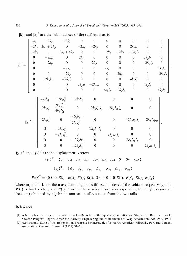
½k1 and ½k2 are the sub-matrices of the stiffness matrix
½k1 ¼
4ks �2ks �2ks 0 0 0 0 0 0 0
�2ks 2ks þ 2kp 0 �2kp �2kp 0 0 2kslc 0 0
�2ks 0 2ks þ 4kp 0 0 �2kp �2kp �2kslc 0 0
0 �2kp 0 2kp 0 0 0 0 2kplb 0
0 �2kp 0 0 2kp 0 0 0 �2kplb 0
0 0 �2kp 0 0 2kp 0 0 0 2kplb
0 0 �2kp 0 0 0 2kp 0 0 �2kplb
0 2kslc �2kslc 0 0 0 0 4ksl2c 0 0
0 0 0 2kplb �2kplb 0 0 0 4kpl2b 0
0 0 0 0 0 2kplb �2kplb 0 0 4kpl2b
266666666666666666664
377777777777777777775
;
½k2 ¼
4ksl2c1 �2ksl
2c1 �2ksl
2c1 0 0 0 0
�2ksl2c1
2ksl2c1þ
4kpl2b10 �2kplb1lg �2kplb1lg 0 0
�2ksl2c1 0
4ksl2c1þ
2kpl2b10 0 �2kplb1lg �2kplb1lg
0 �2kpl2b1 0 2kplb1lg 0 0 0
0 �2kpl2b1 0 0 2kplb1lg 0 0
0 0 �2kpl2b1 0 0 2kplb1lg 0
0 0 �2kpl2b1 0 0 0 2kplb1lg
2666666666666666664
3777777777777777775
;
fy1gT and fy2g
T are the displacement vectors
fy1gT ¼ f zc zb1 zb2 zw1 zw2 zw3 zw4 yc yb1 yb2 g;
fy2gT ¼ ffc fb1 fb1 fw1 fw2 fw3 fw4 g;
WðtÞT ¼ f0 0 0 RðtÞ1 RðtÞ2 RðtÞ3 RðtÞ4 0 0 0 0 0 0 RðtÞ5 RðtÞ6 RðtÞ7 RðtÞ8g;
where m; c and k are the mass, damping and stiffness matrices of the vehicle, respectively, andWðtÞ is load vector, and RðtÞj denotes the reactive force (corresponding to the jth degree offreedom) obtained by algebraic summation of reactions from the two rails.
References
[1] A.N. Talbot, Stresses in Railroad Track—Reports of the Special Committee on Stresses in Railroad Track,
Seventh Progress Report, American Railway Engineering and Maintenance of Way Association, AREMA, 1934.
[2] A.N. Hanna, State of the art report on prestressed concrete ties for North American railroads, Portland Cement
Association Research Journal 5 (1979) 31–61.
ARTICLE IN PRESS
G. Kumaran et al. / Journal of Sound and Vibration 268 (2003) 485–501500
[3] H.P.J. Taylor, The prestressed concrete railway sleepers—50 years of pretensioned, prestressed concrete, The
Structural Engineer 71 (1993) 281–289.
[4] G.C. Agarwal, P.G. Agwekar, Use of high strength concrete for prestressed concrete sleepers in India, Indian
Concrete Journal 6 (1996) 683–686.
[5] Standard Specification for Pretensioned Concrete Sleepers, RDSO Third Revision, Indian Railways, India, 1996.
[6] S.L. Grassie, S.J. Cox, The dynamic response of railway track with flexible sleepers to high frequency vertical
excitation, Proceedings of the Institution of Mechanical Engineers 198-D (1983) 117–124.
[7] K.L. Knothe, S.L. Grassie, Railway track and vehicle/track interaction, Journal of Vehicles System Dynamics 22
(1993) 217–262.
[8] J.C.O. Nielsen, Vertical dynamic interaction between train and track—influence of wheel and track imperfections,
Journal of Sound and Vibration 87 (5) (1995) 825–839.
[9] J. Oscarsson, T. Dahlberg, Dynamic train/track interaction—computer models and full scale experiments, Journal
of Vehicle System Dynamics 29 (1998) 73–84.
[10] B. Ripke, K. Knothe, Simulation of high frequency vehicle–track interactions, Journal of Vehicle System
Dynamics Supplement 24 (1995) 72–85.
[11] G. Kumaran, D. Menon, K.K. Nair, Dynamic response of railtrack sleepers to moving train loads, Proceedings of
EURODYN-02, Swets & Zeitlinger, Lisse, 2002, pp. 1185–1190.
[12] K.V. Gangadharan, Analytical and Experimental Studies on Dynamics of Railroad Vehicles, Ph.D. Thesis,
Department of Applied Mechanics, Indian Institute of Technology, Madras, India, 2001.
[13] V. Dukkipati, J.R. Amyot, Computer-Aided Simulation in Railway Dynamics, Marcel Dekker, New York, 1988.
[14] A.G. Kerr, Proceedings of a Symposium on Railroad Track Mechanics and Technology, Pergamon Press,
Princeton, 1985.
[15] K.J. Bathe, E.L. Wilson, Numerical Methods in Finite Element Analysis, Prentice-Hall, Englewood Cliffs, NJ,
1976.
[16] C.S. Desai, A.M. Siriwardane, Numerical models for track support structures, Journal of Geotechnical
Engineering Division, American Society of Chemical Engineers 108 (1982) 461–480.
[17] J. Dinkel, H. Grundmann, Winkler parameters for railway dynamics derived from 3-D half space analysis,
Proceedings of EURODYN-99, 1999, pp. 831–836.
[18] D. Li, T. Ernest, Wheel/track dynamic interaction—track substructure perspective, Journal of Vehicle System
Dynamics 24 (1995) 183–196.
[19] J.P. Wolf, Foundation Vibration Analysis Using Simple Physical Models, Prentice-Hall, Englewood Cliffs, NJ,
1994.
[20] A.K. Chopra, Dynamics of Structures: Theory and Applications to Earthquake Engineering, Prentice-Hall,
Englewood Cliffs, NJ, 2001.
[21] G. Kumaran, D. Menon, K.K. Nair, Estimation of dynamic loading on railtrack sleepers, Proceedings of the 2nd
International Conference on Wind and Structures, Basan, Korea, 21–23 August, 2002, pp. 127–134.
[22] G. Kumaran, Formulation of Improved Design Basis for Prestressed Concrete Railtrack Sleepers, Ph.D. Thesis,
Dept. of Civil Engineering, IIT Madras, 2002.
[23] G. Kumaran, D. Menon, K.K. Nair, Evaluation of dynamic load on railtrack sleepers based on vehicle-track
modeling and analysis, International Journal of Structural Stability and Dynamics 2 (3) (2002) 355–374.
ARTICLE IN PRESS
G. Kumaran et al. / Journal of Sound and Vibration 268 (2003) 485–501 501