Embed Size (px)
Citation preview
Phillip McNelles, Zhao Chang Zeng, Phillip McNelles, Zhao Chang Zeng,
Dynamic Reliability Analysis of Radiation Induced Failure Modes in
FPGA-based Systems
Dynamic Reliability Analysis of Radiation Induced Failure Modes in
FPGA-based Systems
8th International Workshop on the Applications of FPGAs in NPPs
Shanghai, ChinaOctober 13-16, 2015
Phillip McNelles, Zhao Chang Zeng, and Guna Renganathan
Phillip McNelles, Zhao Chang Zeng, and Guna Renganathan

Presentation OutlinePresentation Outline
• Introduction– Digital system reliability modelling
• Dynamic Reliability
2Canadian Nuclear Safety Commission
• Dynamic Reliability– Dynamic Flowgraph Methodology (DFM)
– Background, Theory and DFM Software (Dymonda)
– DFM/Fault Tree Comparison
– FPGA-based Test System
– DFM/Fault Tree Comparison Results
• Conclusions

IntroductionIntroduction
• Modern reliability methods include dynamic (time-dependent) properties
• Designed to model and analyze modern digital instrumentation and control systems
• Potential for more accurate modelling of FPGA-
3Canadian Nuclear Safety Commission
• Potential for more accurate modelling of FPGA-based systems
• Dynamic modelling of test systems and comparisons with Fault Tree results
• Method chosen was the “Dynamic Flowgraph Methodology” (DFM)
Research PurposeResearch Purpose
• Compare traditional and modern safety analysis methods for analysis of FPGA-based I&C systems– Compare similarities/differences
– Evaluate strengths/weaknesses of each method
4Canadian Nuclear Safety Commission
– Evaluate strengths/weaknesses of each method

DFM BackgroundDFM Background
• Dynamic Flowgraph Methodology
• Inductive and Deductive Analysis
• Dynamic (Time Dependence)
• Equivalent of Fault Tree and FMEA in one model
5Canadian Nuclear Safety Commission
• Equivalent of Fault Tree and FMEA in one model
• Probabilities and Uncertainties
• Used in Nuclear and Aerospace Applications
• ASCA Inc. (Applied Science Consulting Firm)
• Dymonda Software
• VTT (Finland) created a separate version

DFM Background (Models)DFM Background (Models)
• Directed Graph Model (Signal Flow Graph)– All DFM models contain nodes, transfer boxes, edges
• Nodes: – Process Variables
6Canadian Nuclear Safety Commission
– Process Variables
• Transfer/Transition Boxes:– Describe relationship/transfer function (Transition Tables)
• Edges– Connect Nodes/Boxes

DFM Background (Rationale)DFM Background (Rationale)
• Time Dependant– Feedback
– Control Loops
• Multi Valued Logic (MVL)
7Canadian Nuclear Safety Commission
• Multi Valued Logic (MVL)
• Complete System Model
• Issues– Computationally intensive (“State Explosion”)
– Need detailed information

DFM TheoryDFM Theory
• Minimal Cut Set (MCS)1,2
– A set of events that cause the top event if they occur (Cut Set)
– A cut set that does not contain other cut sets as a subset (MCS)
8Canadian Nuclear Safety Commission
as a subset (MCS)
(1)
(2)
DFM TheoryDFM Theory
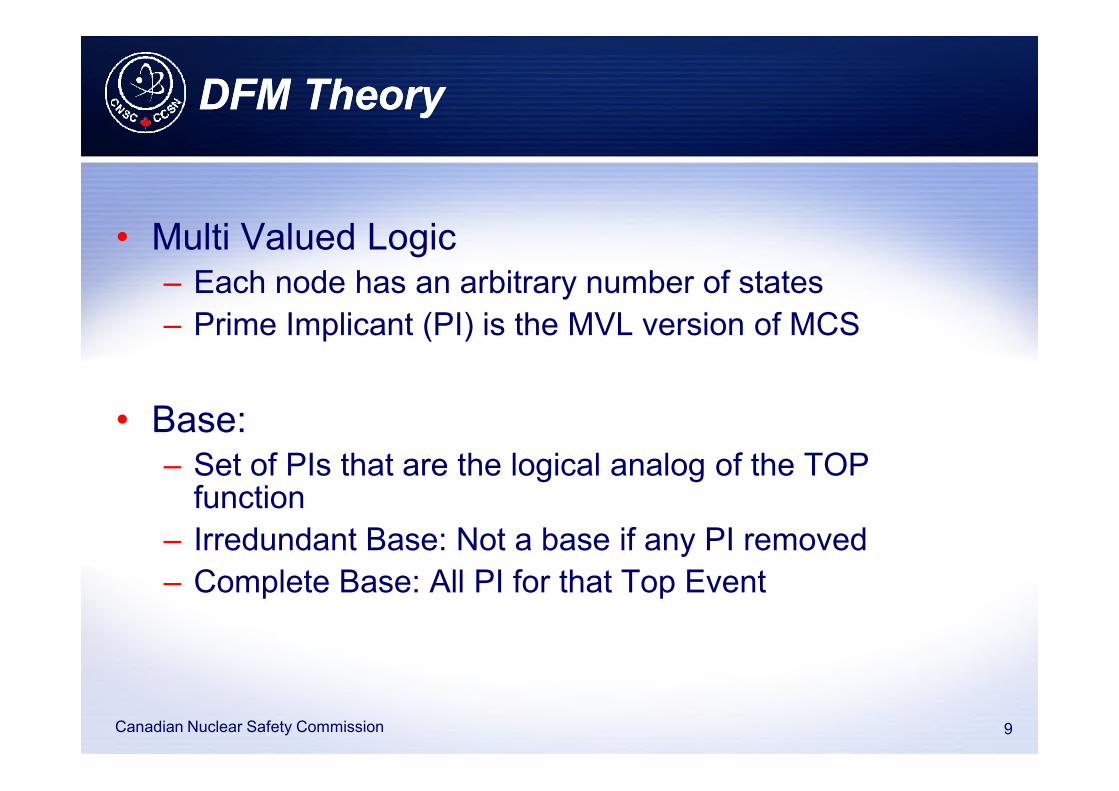
• Multi Valued Logic– Each node has an arbitrary number of states
– Prime Implicant (PI) is the MVL version of MCS
9Canadian Nuclear Safety Commission
• Base:– Set of PIs that are the logical analog of the TOP
function
– Irredundant Base: Not a base if any PI removed
– Complete Base: All PI for that Top Event

DFM TheoryDFM Theory
• Restrictions on DFM Analysis– Physical Consistency Rules
– Variable must take on one state
– Cannot have multiple states (per time step)
– Sum of PI gives Top Event1,2
10Canadian Nuclear Safety Commission
– Sum of PI gives Top Event1,2
(3)
(4)
(5)

DFM Theory and Dymonda (Software)DFM Theory and Dymonda (Software)
• Timed Fault Tree (TFT) Construction
– System backtracks through model from top event
– Order based on model’s logical sequence
11Canadian Nuclear Safety Commission
• Timed Prime Implicant (TPI) Identification
– Software creates “Critical Transition Table”
– Logic reduction operations produce PIs

Dymonda Features (Software)Dymonda Features (Software)
• Dynamic Consistency Rules– Increasing/Decreasing
– Rate Rules
– Sink States
12Canadian Nuclear Safety Commission
• Probabilities and Uncertainties
• Exact Quantification (EQ)– Standard DFM probability is the sum of all PI
– Convert PI to “Mutually Exclusive Implicants” (MEI)

DFM vs Fault Tree ComparisonDFM vs Fault Tree Comparison
• DFM/Dymonda designed to model digital control systems
– FPGA-based systems are digital systems
– Potential for better modeling and analysis
• Little information on comparisons between results from Fault Tree Analysis (FTA) and DFM models2
13Canadian Nuclear Safety Commission
Fault Tree Analysis (FTA) and DFM models2
• More research should be done to compare these methods
• CAFTA software (EPRI) used to create fault trees for comparison

DFM vs Fault Tree ComparisonDFM vs Fault Tree Comparison
• Some Comparisons from US NRC documents
• “…the application of the DFM or Markov/CCMT techniques has been capable of identifying several risk relevant sequences that were not
14Canadian Nuclear Safety Commission
several risk relevant sequences that were not included in conventional PRA models.”3
• “…, the ET/FT approach has been found to overestimate the predicted Top Event frequencies”4

DFM and FTA (Preliminary Comparison)DFM and FTA (Preliminary Comparison)
• Preliminary DFM/FTA Comparisons• Static systems
• Simple dynamic systems (register)
– Preliminary Results
15Canadian Nuclear Safety Commission
– Preliminary Results• Same results for static systems
• Very similar results for simple dynamic systems
• Next phase involved a more complex dynamic system

Test SystemTest System
• Modelling will be performed on a test system
– Reactor Trip Logic developed with a reference to:
• EPRI TR-1093905
16Canadian Nuclear Safety Commission
• Westinghouse AP1000 (Ch. 7)6,7
– Sub-Systems include
• Analog-to-Digital Converter (ADC)
• Sanity Check (SC)
• Trip Parameter Calculation (Overtemperature)
• Comparator (COMP)

Test SystemTest System
• Test System– Single Channel, Single Parameter (Over Temperature)
– Three redundant circuits with voting logic
• Difference from US NRC Research
17Canadian Nuclear Safety Commission
• Difference from US NRC Research– NRC project took a macroscopic approach
• Complete system (Computer, Valve, Pumps, etc)
– This project focused on design of FPGA-based systems• Considered registers, mux, decoders, logic gates, etc.
• Failure modes due to SEE, aging process and human factors
• Common Cause Failures (CCF) not included at this point

Test System Model (Overview)Test System Model (Overview)
18Canadian Nuclear Safety Commission
High Level Block Diagram for FPGA-based Test System

Test System Model (COMP)Test System Model (COMP)
19Canadian Nuclear Safety Commission
FPGA Comparator Flowgraph Model5,6

Test System AnalysisTest System Analysis
• Two Top Events– Spurious Trip
– Missed Trip
20Canadian Nuclear Safety Commission
• Comparison Included Several Factors:– Total Probability
– Number of PI/MCS
– Similarities/Differences between PI/MCS
– Birnbaum Structural Importance (BSI) Measures

Comparison Results (Top Event)Comparison Results (Top Event)
Model Clock
State
CSG DPC MCS #
Missed Trip 1 6.67E-05 1.09E-05 1079
Missed Trip 0 1.27E-08 4.25E-09 9
Spurious
Trip
1 1.35E-06 1.59E-06 663
Spurious 0 2.03E-06 7.10E-07 69
Model SUM/MCSUB EQ PI #
Missed Trip 1.556E-05 1.554E-05 53
Spurious Trip 3.117E-05 3.116E-05 63
21Canadian Nuclear Safety Commission
Spurious
Trip
0 2.03E-06 7.10E-07 69
FTA (CAFTA) Results DFM (Dymonda) Results
Nomenclature:CSG (Cut Set Generator)DPC (Direct Probability Calculator)MCSUB (Minimal Cut Set Upper Bound)EQ (Exact Quantification)
Comparison Results (PI/MCS)Comparison Results (PI/MCS)
Node State Time Step Probability Node State Time Step Probability
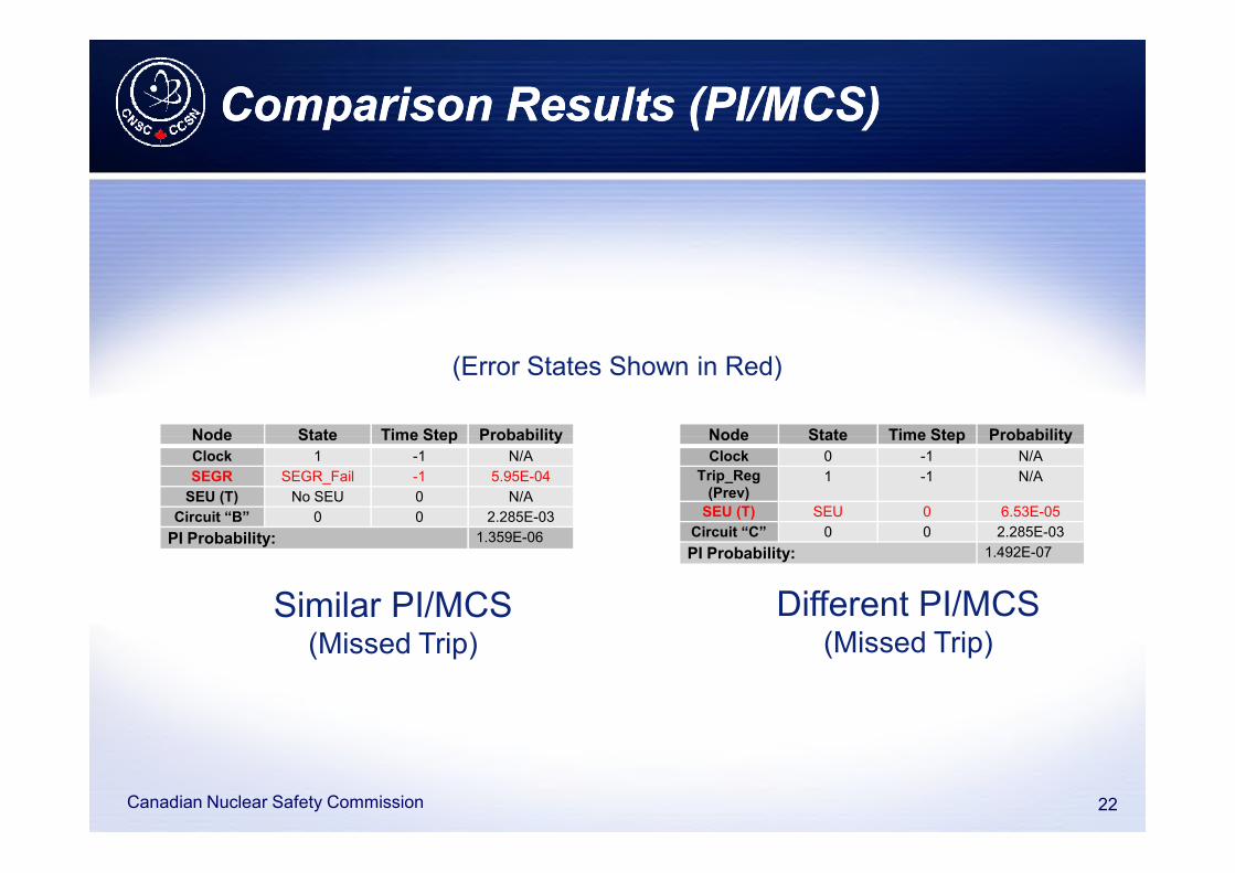
(Error States Shown in Red)
22Canadian Nuclear Safety Commission
Node State Time Step Probability
Clock 1 -1 N/A
SEGR SEGR_Fail -1 5.95E-04
SEU (T) No SEU 0 N/A
Circuit “B” 0 0 2.285E-03
PI Probability: 1.359E-06
Node State Time Step Probability
Clock 0 -1 N/A
Trip_Reg(Prev)
1 -1 N/A
SEU (T) SEU 0 6.53E-05
Circuit “C” 0 0 2.285E-03
PI Probability: 1.492E-07
Different PI/MCS(Missed Trip)
Similar PI/MCS(Missed Trip)

Comparison Results (BSI)Comparison Results (BSI)
Node DFM FTA(Clock 0)
FTA(Clock 1)
SEU (T) 0.981 0.996 0.999
CE (D) 0.825 0.996 0.999
Birnbaum Structural Importance (BSI):
23Canadian Nuclear Safety Commission
CE (D) 0.825 0.996 0.999
SHE (P) 0.698 0.996 0.998
SED (Q)(DFM)
0.667 0.98 0.997
SEGR (FTA)
0.475 0.996 0.998
SEDB (FTA)
0.475 0.996 0.998
Node BSI Comparison
•Compares relative component importance•Number of PI/MCS containing a node/state divided by the total
number of PI/MCS •Does not require probabilities

Potential DifferencesPotential Differences
• Potential reasons for differences between DFM and FTA results:– Initial Conditions
– Time Steps
– Retention
24Canadian Nuclear Safety Commission
– Retention
– Circular Logic
– Truncation

ConclusionConclusion
• DFM is a form of Time-Dependent reliability analysis that can be performed using the Dymonda software
• FMEA data used to inject failures into test system
25Canadian Nuclear Safety Commission
• FTA and DFM analysis performed on test system
• Preliminary Results:
– Similar results for static and simple dynamic systems
– Noticeable differences for large, dynamic systems
– Future work including• Common Cause Failures
• Quantitative Measures (Sensitivity, Importance measures)

ReferencesReferences
[1] ASCA Inc., 2013, Dymonda 7.0 Software Guide, ASCA Inc., Redondo Beach, California.
[2] Chu, T.L. et al, 2009, Modeling a Digital Feedwater Control System Using Traditional Risk Assessment Methods, U.S. Nuclear Regulatory Commission, Washington D.C.
[3] Aldemir, T., Guarro, S., Kirshenbaum, J., and et, al, 2009, A Benchmark Implementation of Two Dynamic Methodologies for the Reliability Modeling of Digital Instrumentation and Control Systems, U.S. Nuclear Regulatory Commission, Washington DC.
[4] Aldemir, T., Miller, D. W., Stovsky, M. P., and et, al, 2006, Current State of Reliability Modeling Methodologies for Digital Systems and Their Acceptance Criteria for Nuclear
26Canadian Nuclear Safety Commission
Modeling Methodologies for Digital Systems and Their Acceptance Criteria for Nuclear Power Plant Assessments, U.S. Nuclear Regulatory Commission, Washington DC.
[5] Electric Power Research Institute, (EPRI),1997, Design Description of a Prototype Implementation of Three Reactor Protection System Channels Using Field-Programmable Gate Arrays, EPRI, Oak Ridge Tennessee.
[6] AP1000 Design Control Document (Revision 15), Chapter 7: Instrumentation and Controls, Westinghouse.
[7] Park, Jin-Ho et al, 1992, Optimization of Dynamic Terms in Core Overtemperature
Delta-T Trip Function, Korea Atomic Eenrgy Research Institute, pp. 236-242..

The EndThe End
• Thank you for your time– Questions?
27Canadian Nuclear Safety Commission
E-mail: [email protected]

Canadian Nuclear Safety Commission
Canadian Nuclear Safety Commission
nuclearsafety.gc.canuclearsafety.gc.canuclearsafety.gc.canuclearsafety.gc.ca
© CNSC Copyright 2013
facebook.com/CanadianNuclearSafetyCommission
youtube.ca/cnscccsn