Embed Size (px)
Citation preview

DYNAMIC PROGRAMMING AND DIRECT ITERATION FOR
THE OPTIMUM DESIGN OF SKELETAL TOWERS
G.C. Howell and W.S. Doyle
University of Cape Town, Rondebosch, South Africa
ABSTRACT
A computer technique is proposed for a simple practical method of auto- matically designing tower structures. Dynamic programming is used to find the optimum geometric configuration of the structural members, while the member sizes are proportioned by direct iteration.
Tower structures are particularly suited to this method of automatic design since the rapidity of the analysis and design depends primarily upon substructuring. Substructuring of towers is comparatively simple because interaction between adjacent substructures can be simulated with reasonable accuracy. Typical examples are presented to illustrate the method.
INTRODUCTION
Dynamic programming has long been recognised as an extremely powerful optimization technique, particularly for problems of a discontinuous nature. High-dimensional problems, however, result in a large amount of computation, but this can be reduced by a successive approximation method.
A 3-dimensional Dynamic Programming Successive Approximation technique is used here to obtain an optimum (least weight) geometrical configuration for the design of tower structures. Concurrently, a simple direct itera- tion procedure is used to select the optimum member sizes from any list of section properties provided.
If the structure were to be designed as a whole, a change of geometric configuration would need a re-analysis. This means that a large amount of computation would be required.
Substructuring has been introduced to reduce the overall problem into smaller stages so that the analysis can be performed more rapidly.
If any sections recommended by the computer are not desirable for practical reasons the re-input of a complete new set of data is unnecessary. Only the list(s) of sections and the data relating to section types need be changed.
101
https://ntrs.nasa.gov/search.jsp?R=19790002286 2018-09-05T21:31:50+00:00Z

Three examples of tower structures are given in this paper:
1. A sample plane-truss tower 2. A comparison of the optimum weight of a triangular tower referred to by
Kuzmanovic, Willems and Thomas (ref. 1) 3. A typical transmission tower used in South Africa
DYNAMIC PROGRAMMNG - BASIC CONCEPTS
The computational effort required to find all the possible solutions for large problems can become unmanageable without the use of Dynamic Programming. This technique bypasses this problem by considering the possible decisions to be made at each stage of the solution.
Dynamic Programming can be described as a technique for methodically selecting an optimum solution of a multi-stage decision problem. This mathematical technique can be used for problems where a sequence of decisions are dependent upon one another and each decision influences the system's response to future decisions. A set of solutions can be categorized so that one may be judged to be better than another in some pre-defined manner.
In a sequence of decisions, the current state of the sequence is assessed as f(x(k-1)) and the succeeding one as f(x(k)). Without considering the whole chain of past and future decisions, except that they contribute to f(x(k-l)), the best decision can be found from:
f(x(k)) = min[t(x(k); x(k-1)) + f(x(k-l))]
where t is the assessment between stages k-l and k and x is a state variable
Dynamic Programming is based on a repeated use of this idea.
A simple network problem posed by Bellman and Dreyfus (refs. 2 & 3) and discussed by Palmer (ref. 9) demonstrates the process excellently. In the course of the solution of this problem, two central ideas are used. The first is the idea of imbedding; this means that the overall optimization problem consists of a number of smaller problems imbedded within the whole, which can be solved independently. In the second idea, an optimum solution can be found from a sequence of decisions by imagining that the final solution is broken up into a series of simpler decisions.
Problems of this type become very tedious when the order of the state variables (x(k)) becomes large. For example, various state variable vectors (denoted x (k)) may be present at any particular stage k of the calculation, which camp f- lcates the matter. For this reason, the dimension (n) of the problem is decreased to a single variable vector by the use of the Dynamic Programming Successive Approximation (DPSA) technique.
102

The geometric design of a tower structure can be degenerated into a series of simple decision processes as prescribed by the DPSA technique by using substructuring.
SURSTRUCTURING
The benefit of substructuring in the design of towers is that the optimum section sizes can be determined rapidly within each substructure. The inter- action between adjacent substructures is comparatively simple and can be simulated with reasonable ease which makes this technique particularly attractive.
The geometry at the interface of each substructure is uniquely defined by the coordinates of the member ends which are 'cut' at the interfaces. Hence, in Figure 1, the coordinates at the right hand side of substructure 1 are defined by x , y ; x1, yl and for substructure 2 by x1, yl; x2, y2 and so on for thg other substructures.
The assumption is made that the forces transferred from one substructure to the next can be calculated from statics. For example, the interaction forces at the interface between substructures 1 and 2 are found by applying equivalent loads and moments at the central point A; i.e., the vertical force P is resolved into a load P force PC
and a moment P x h, while the horizontal is resolved into a load Pl and a moment P ; x (Y4 - Y,).
Each pin-jointed substructure is analysed by the displacement method, which requires the equivalent loads and moments at A to be applied as point loads at the interface nodes (xl, y,) and (-x , y now analysed and designed independently assuming t
). The substructures are hat the lower interface
nodes are constrained. The member sizes are selected by a simple direct iteration procedure.
DIRECT ITERATION
A list of sections is provided so that the actual member sizes required in each substructure can be selected automatically by the direct iteration procedure. The calculated stresses are compared with permissible stresses so that the ratio between them is a minimum. The substructure is reanalysed each time the member sizes are revised until the results from successive iterations are identical.
THE DYNAMIC PROGRAMMING SUCCESSIVE APPROXIMATION (DPSA) TECHNIQUE
The coordinates of the interface nodes in Figure 1 can be changed at any stage and the members designed accordingly by the direct iteration method.
103

Consequently, the weight of each configuration of members in all substructures can be calculated. The optimum solution is then the combination of possible configurations which results in the least weight of the total structure. The dynamic programming technique sets about this calculation in an organized methodical way.
Let us consider a tower similar to that in Figure 1. The interface nodes, which define the configuration of the tower, can be positioned 'in space by a set of three-dimensional coordinate values. Let the structure be symmetrical about the XZ and YZ planes; therefore a node placed in the first o&ant wiil define the shape of the tower at that level. Let the coordinates of the interface node be (x x, y and z coordinates of t iJi
(k), x2(k), x3(k)). This corresponds to the e primary node of substructure 1, where k also
denotes the upper interface level of that substructure and k = 0 represents the ground level. The n-dimensional DPSA method is therefore well suited to structures of this type, where n = 3. For example, at level k = 2 some possible values of the state variables are shown in Table 1. The control variables un(k) shown correspond to the identification number in each set.
The values of u(k) (i.e. u x (k), x (Id, x3(k) at each leve 1 z
(k), u (k), u3(k)) and hence the values of
o+ fi k mus be found so that the overall weight
the s ructure is a minimum.
The DPSA method requires an initial solution to the problem. The average value of the state variables at each interface is a suitable initial solution. To proceed, only one state variable is altered, while the remainder stay at their initial values. In this way a single-dimensional dynamic programming procedure with respect to this variable is carried out. The process is then continued, the new value of the first variable is retained and one of the other state variables is altered. All the variables are processed in this way; the first cycle is complete when all the state variables have been altered. Subsequent cycles follow the same procedure as above. The DPSA method has converged to its optimum solution when no weight difference is recorded between successive cycles. This method is found to converge rapidly to an optimum weight solution. The structure comprises a number of substructures. The geometric configuration between interfaces is regarded as a substructure.
The direct iteration method is used to find the most satisfactory structural design and hence the weight for every geometric configuration of each substructure. A least weight path is followed through all the sub- structures to determine the optimum configuration of the total structure. The explanation of the DPSA method can be simplified by the following elementary example.
Example: Consider a simple 2-dimensional tower which consists of 2 substructures - Figure 2.
Let the state variables x(l) and x(2) vary in three steps on each side of the vertical axis of symmetry and the other state variables i.e. y(k) be kept constant. In addition, let the state variable x(k) at k = 0 be
104

constrained to a single value. The accumulated cost (or weight) of the sub- structures up to level k for each position of x can be denoted by:
Ci(k) where i denotes the position of x(k) on interface k. Let the cost of a single substructure,k be denoted by:
tij (k) where i and j denote the positions of the state variables x(k) for sub- structure k at the upper and lower interfaces respectively.
Figure 3 shows all the possible geometrical configurations within the constraints given.
The costs of each of the 3 configurations in the first substructure, due to the varying values of x(l), are calculated by:
Cl(l) = tll(l) C*(l) = t*1(1) c3(1) = t31(1)
and are shown in Figure 4.
Similarly the values of t..(2) can be obtained for the second sub- structure. The least accumul&$ed weight at point i on interface k can be found from:
Ci(2) = min[tij(2) + Cj(l)] for j = 1 to 3
The optimum configuration of the structure at level 2 is determined by choos- ing the least value of C.(2). The optimum path can then be traced back through the calculations'to find the optimum configuration of the entire structure.
A computer program, which uses the ideas discussed above, has been written to design general tower structures. Three examples included are: a. A simple 3-cell plane-truss tower. b. A 3-legged transmission tower. C. A practical, rectangular plan transmission tower.
Example 1. 3-substructure plane-truss tower The tower shown in Figure 5 supports two loads at the upper level of
-15 kN in the y-direction and -10 kN in the x-direction at nodes 7 and 8 respectively. The possible dimensions at the 4 levels are, in x-direction:
1 2 3 4 5 Base 136 138 230 232 2,4 Level 1 131 193 195 197 139 Level 2 038 039 1,o 131 132 Level 3 095 and in z-direction:
105

1 3 4 5
Base 030
Level 1 138 199 Level 2 39 1
?i 2,1 41 2-z Level 3 : : 1
Each substructure is to be designed using the following sections: 1. Upright member - channel sections. 2. Diagonal member - pipe sections 3. Horizontal member - angle sections.
Results: The final shape is shown in Figure 6.
Structural Design: Substructure Members Size - mm
1 a,d loo x 50 x 6 Channel b,c 38,~ x 2 Pipe e 40 x 40 x 3 Angle
2 f,i loo x 50 x 6 Channel g,h 38,~ x 2 Pipe j 25 x 25 x 3 Angle
3 k,n 76 x 38 x 5,1 Channel R,m 48,5$ x 2 Pipe 0 25 x 25 x 3 Angle
Total weight of structure, 1,461 kN; total computer time, 28,X9 set UNIVAC 1106.
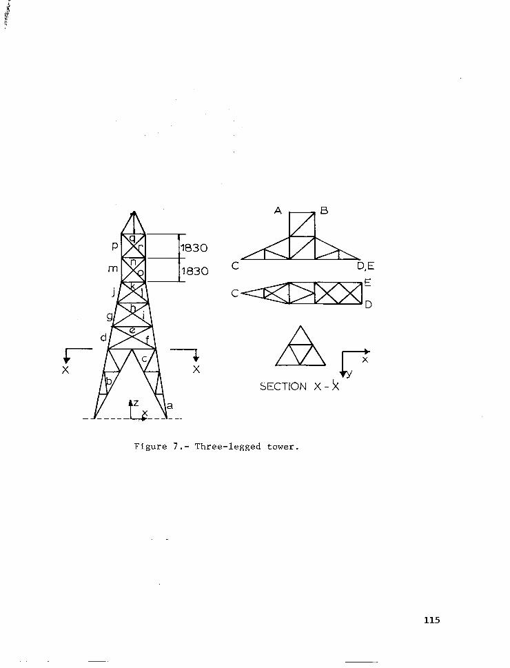
Example 2. A three-legged transmission tower shown in Figure 7 is considered. It contains 56 nodes and 175 members. The loads used correspond to those used by Kuzmanovic et al. (ref. 1).
Load case 1: Basic wind free in transverse direction Position Load kN Direction
A,B 26,7 - z 8,9 -x
C 80,o - z 31,o -x
D,E 15,6 -x 40,o - z
Load case 2: 0,707 Basic wind in the transverse direction 0,707 Basic wind in the longitudinal direction
Position
A,B
C
D,E
Load kN Direction 16,o - z
594 -x 48,0 - z 18,7 -x
994 -x 11,6 +Y 24,o - z
106

Load case 3: No wind Position Load kN
A,B 32,0 c 160,o D,ti - 80,o
Direction -z - z - z
Member Groups: Table 2 shows the member groups used in each substructure.
Angle sizes: Table 3 shows the list of angles which were used to produce a structural design.
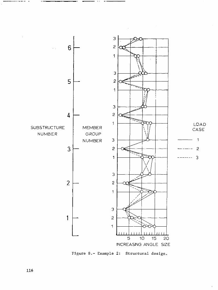
Results: The structural design for each load case is shown in Figure 8. The horizontal axis represents, in ascending order, *the sizes of angle avail- able for the design. The vertical scale represents the member groups within each substructure. Computer times and structure weights are:
Load case
1 2 3
No.of state variable positions at each level Horizontal Vertical
(radial) (elevation) 5 1 5 1 5 1
Weight kN Computer time
UNIVAC 1106
23,256 6 min 27 set 16,786 4 min 12,17 set 17,428 3 min x6,89 set
The optimum weight found by Kuzmanovic et al. (ref. 1) was 23,51 kN. The weights above compare favourably with this value.
Example 3. A practical transmission tower similar to those currently in use in South Africa is considered. It contains 115 nodes and 336 members. The shape of tower is shown in Figure 9. An equivalent set of loads have been calculated from those used in Example 2. Angle sizes used in the design are shown in Table 3.
Member Groups: Table 4 shows the member groups used in each substructure.
Results: The structural design for each load case is shown in Figure 10. Computer times and structural weights are: Load case No-of state variable
positions at each level Weight kN Computer time
1 2
x-dir. y-dir. z-dir. UNIVAC 1106 3 3 1 57,877 46 min 04,252 set 3 3 1 48,544 31 min 15,069 set
CONCLUSION
This method of automatically determining the optimum geometric configura- tion and member sizes substantially reduces the effort involved in the design
107

of tower structures. The dynamic programming successive approximations technique is effective for structures of this type, where substructuring pro- vides the necessary static variables. The displacement method is admirably suited to the analysis of these structures. Direct iteration is the simplest method of selecting the optimum member sizes from any given list of section properties. Three examples have been discussed. In the 15 member plane- truss example considered as 3 substructures, the computational time taken on a UNIVAC 1106 is 28,39 seconds. A waisted tower shape of structure is the optimum geometric solution. Example 2 is a three-legged tower with 175 members and 56 nodes. The computational time with two state variable6 is 6 minutes 27 seconds. The weight compares favourably with that given in reference.11 by Kuzmanovic et al. Example 3 is a practical transmission tower similar to those currently used in South Africa. This structure consists of 336 members and 115 nodes and the computational time required for an optimum feasible solution is 46 minutes per load case.
108
!i i’
Q
1.
2.
3.
4.
REFERENCES
Kuzmanovic, B-0.; Willems, N.; and Thomas, F-M.: Automated Design of Three- Legged Steel Transmission Towers. Computer & Structures, vol. 7,.1977, pp. 171-182.
Bellman, R.E.: Dynamic Programming. Princeton University Press (Princeton, N.J.), 1957.
Bellman, R.E.; and Dreyfus, S-E.: Applied Dynamic Programming. Princeton University Press (Princeton, N.J.), 1962.
Palmer, A.C.: Dynamic Programming and Structural Optimization. Int. Symposium on Computers in Optimization of Structural Design (University of Wales, Swansea), January 1972.
BIBLIOGRAPHY
Larson, R.E.: A Survey of Dynamic Programming Computational Procedures. IEEE Transactions of Automatic Control, vol. AC-12, 1967, pp. 767-774.
Larson, R.E.; and Korsak, A.J.: A Dynamic Programming Successive Approximation Technique With Convergence Proofs. Automatica, vol. 6, 1970, pp. 245-260.
Larson, R.E.: State Increment Dynamic Programming. American Elsevier (New York), 1968.
Packia Raj, P.; and Olani Durrant, S.: Optimum Structural Design by Dynamic Programming. J. Struct. Div. ASCE, vol. 102, no. STY, 1976, pp. 1575-1589.
Palmer, A. C.: Optimum Structure Design by Dynamic Programming. J. Struct. Div. ASCE, vol. 94, no. ST8, 1968, pp. 1887-1906.
Palmer, A. C.; and Sheppard, D.J.: Optimizing the Shape of Pin-Jointed Structures. Proc. of Inst. of Civ. Eng., vol. 47, 1960, pp. 363-376.
Sheppard, D.J.; and Palmer, A.C.: Optimal Design of Transmission Towers by Dynamic Programming. Computers & Structures, vol. 2, 1972, pp. 455-468.
Weaver, W.; and Patton, F.W.: Automated Design of Space Trusses. AISC Engineering Journal, vol. 5, 1968, pp. 26-36.
109

TABLE 1 - A POSSIBLE SET OF STATE AND CONTROL VARIABLE VECTORS
STATE VARIABLES x,(k) IDENTIFICATION n=lto
x1(2) x2(2) x3(2) u(2)
038 097 099 1 0,9 0,75 0,95 2 130 0;8 130 191 0,85 I,05 4’ 132 039 191 5
NO u,(k) 3
Wee 1 2 3 4 5
TABLE 2 - MEMBER GROUPS
Substructures
Main leg members, a Horizontal leg members, b
Diagonal leg members, c Main leg members, d,g,j,m,p Horizontal members, e,h,k,n,q Diagonal members, f,i,ll,o,r
1 2
3
1 1 1 1 2 2 2 2
3 3 3 3
i10

Number
1 25 x 25 x 3 2 30 x 30 x 3 3 40-x 40 x 3 4 45 x 45 x 3 5 45 x 45 x 5 6 50 x 50 x 5 7 60 x 60 x 5 8 60 x 60 x 6
9 70 x 70 x 6 10 80 x 80 x 6
TABLE 3 - AVAILABLE ANGLE SIZES
Size - mm Number
11 80 x 80x 8 12 90 x 90x 8 13 100 x loo x 8 14 100 x 100 x 10
15 120 x 120 x 10 16 120 x 120 x 12
17 150 x 150 x 12 18 150 x 150 x 18
19 200 x 200 x 16
20 200 x 200 x 24
Size - mm
TABLE 4 - MEMBER GROUPS
Type 1 Main leg members, a,f,j 1 Secondary leg members, b,g,k 2
Leg horizontal members, c 3 Diagonal members, d 4 Interface members, e,i,m 5 Leg bracing members, h,R Main arm members, n Secondary arm members, o Bracing, P,q,r,s,t,u Boom members, v,w
Substructures 2 3 4
1 1 2 2
4
3 1 I
2
3,4,5,6,7,8 9,lO
111

b&-Y,)
SUBSTRUC TURE
Figure l.- Tower structure with substructures.
CONSTANT
Figure 2.- Tower structure (example).
112

POSITION
k=2 .- - -- --_--_ I
k=O
I 1 k=l -----------
SYMMETRIC
k=O --_----
Figure 3.- Possible configurations.
POSITtON
1 2 3
Figure 4.- Three cost values.
113

I 15 kN
Figure 5.- Original tower shape.
I 15 kN
LEVi’L 3
LEVEL 2
LEVEL 1
BASE
I- 2400
Figure 6.- Optimum tower shape.
114
P
C D,E
E C
D
+Y
SECTION X - k
Figure 7.- Three-legged tower.
115
4
SUBSTRUCTURE
NUMBER
3
2
1
MEMBER GROUP
NUMBER
7
i
1
.
;
,
‘;
2
1
3
2
1
3
2
1
3
2
1
INCREASING ANGLE SIZE
LOAD CASE
1
de--- 2
------_ 3
Figure 8.- Example 2: Structural design.
116

t . 9300 I
Figure 9.- Typical tower.
117

4
3
SUBSTRUCTURE
NUMBER
2
1
-
MEMBER
GROUP
NUMBER
10
9
a
7
6
5
4
3
2
1
4
3
2
1
4
3
2
1
5
4
3
2
1
LOAD CASE
1
5 10 15 20
INCREASING ANGLE SIZE
Figure lo.- Example 3: Structural design.
118