Embed Size (px)
Citation preview

21
Dynamic Modelling and Vibration Control of a Planar Parallel Manipulator with Structurally
Flexible Linkages
Bongsoo Kang1 and James K. Mills2 Hannam University1,
University of Toronto2 South Korea1
Canada2
1. Introduction
A parallel manipulator provides an alternative design to serial manipulators, and can be found in many applications such as mining machines (Arai et al., 1991). Through the design of active joints such that actuators are fixed to the manipulator base, the mass of moving components of the parallel manipulator is greatly reduced, and high speed and high acceleration performance may be achieved. Parallel manipulators, comprised of closed-loop chains due to multiple linkages of the parallel structure, also provide high mechanical rigidity, but adversely exhibit smaller workspace and associated singularities. Considerable research has focused on kinematic analysis and singularity characterization of these devices (Gosselin & Angeles, 1990, Merlet, 1996). Planar parallel manipulators typically consist of three closed chains and a moving platform. According to the arrangement of their joints in a chain, these mechanisms are classified as PRR, RRR etc. where P denotes a prismatic joint and R denotes a revolute joint respectively. An assembly industry, such as the electronic fabrication, demands high-speed, high acceleration placement manipulators, with corresponding lightweight linkages, hence these linkages deform under high inertia forces leading to unwanted vibrations. Moreover, such multiple flexible linkages of a parallel manipulator propagate their oscillatory motions to the moving platform where a working gripper is located. Therefore, such vibration must be damped quickly to reduce settling time of the manipulator platform position and orientation. A number of approaches to develop the dynamic model of parallel manipulators with structural flexibility have been presented in the literature(Fattah et al., 1995, Toyama et al. 2001), but relatively few works related to vibration reduction of a parallel manipulator have been published. Kozak (Kozak et al., 2004) linearized the dynamic equations of a two-degree-of-freedom parallel manipulator locally, and applied an input shaping technique to reduce residual vibrations through modification of the reference command given to the system. Kang (Kang et al., 2002) modeled a planar parallel manipulator using the assumed modes method, and presented a two-time scale controller for linkage vibration attenuation of the planar parallel manipulator. Since both the input shaping technique and the two-time scale control scheme, applied to parallel manipulators,
Source: Parallel Manipulators, New Developments, Book edited by: Jee-Hwan Ryu, ISBN 978-3-902613-20-2, pp. 498, April 2008, I-Tech Education and Publishing, Vienna, Austria
Ope
n A
cces
s D
atab
ase
ww
w.in
tehw
eb.c
om
www.intechopen.com

Parallel Manipulators, New Developments
406
can only control command inputs to joint actuators of a manipulator, their performance on vibration reduction of flexible linkage are limited. This chapter introduces a methodology for the dynamic analysis of a planar parallel mechanism beginning with the rigid-body model of a planar parallel manipulator. Flexible deformations of each linkage are expressed by the product of time-dependant functions and position-dependant functions, i.e. an assumed modes model. Overall dynamic equations of the motion for a planar parallel manipulator are formulated by Lagrangian equations. Then, an active damping approach using piezoelectric material actuators is presented to damp out oscillation of linkages of a planar parallel manipulator. Also an integrated control scheme is designed to permit the platform of the parallel manipulator to follow a given trajectory while simultaneously damping structural vibration of flexible linkages. Attached directly to the surface of flexible linkages, piezoelectric materials deform under an applied control voltage, producing shear forces, which counteract shear stresses that occur due to deformation of the linkages. Transducers are often developed from either of two types of material: polyvinylidene fluoride (PVDF) or lead zirconium titanate (PZT). PVDF is lightweight and is mainly used as a measurement device for detecting vibration, although the PVDF can also be used as an actuator. PZT has been used as actuators for micro mechanisms and has a higher strain constant than PVDF. In simulations, both the PZT and PVDF piezoelectric actuators are applied to a planar parallel manipulator with flexible linkages and the respective performance of two actuators are compared. The dynamics of the planar parallel platform are selected such that the linkages have considerable flexibility, to better exhibit the effects of the vibration damping control system proposed. Simulation results show that the PZT actuator can give better performance in vibration attenuation than the PVDF layer.
2. Rigid-body analysis of a planar parallel manipulator
2.1 Architecture of a planar parallel manipulator
Fig. 1. Configuration of a PRR type planar parallel manipulator
The architecture of a PRR type parallel mechanism is illustrated in Fig. 1. The underline of the first character of PRR means that the first Prismatic joint is an active joint derived by
PlatformIntermediate link
Slider
Linear guide
www.intechopen.com

Dynamic Modelling and Vibration Control of a Planar Parallel Manipulator with Structurally Flexible Linkages
407
actuators. The moving platform, a regular triangular shape, exhibits translation and rotational motion in a plane. Three intermediate links between the moving platform and sliders play a role to convert the actuating force into movements of the platform. Both ends of the intermediate link are composed of non-actuated revolute joints. The sliders move along the linear guide and their motions can be achieved by a ball-screw mechanism. The proposed planar manipulator is categorized as a PRR type, because a closed-loop chain consists of a prismatic joint and two consecutive revolute joints. In contrast to well-known RPR type parallel manipulators, actuators of the proposed PRR configuration remain stationary that results in low inertia of moving parts. Workspace analysis of a planar parallel manipulator has been addressed (Gosselin et al., 1996, Heerah et al., 2002) and singularity analysis of a planar parallel manipulator has been studied (Gosselin & Angeles, 1990, Merlet, 1996).
2.2 Kinematics
Fig. 2. Coordinate system of rigid-body model We will begin with formulation of the rigid-body model of the proposed planar parallel manipulator, and then include structural flexibility of the linkage in Section 3. Prior to derivation of dynamics of the parallel manipulator, the inverse kinematic solution of the manipulator is formulated to define kinematic relations between active joints, and position and orientation of the platform. Then, based on these kinematic relations, equations of the motion for a parallel manipulator are formulated later. Generalized coordinates for the PRR manipulator are defined, as shown in Fig. 2. The position of the reference X-Y frame is arbitrary.
iA is the origin of the ith linear guide and iB
is the position of the ith slider. iC is the position of the revolute joint of the platform facing
with the ith linkage and P is the position of the platform at its mass center. Three linkages, including associated coordinates, are numbered with a subscript, i, starting from the lower
b1
b2
b3
A1
C1
B1
1ρ
2ρ
3ρ1β
1α
X
Y
A3
A2
C2
C3
B2
B3
e1 e2
e3 P
3α3β
2β
www.intechopen.com

Parallel Manipulators, New Developments
408
right link in a counterclockwise direction. The pose of the moving platform at its mass center can be written with respect to the reference X-Y frame as
PX := [ ]TPP yx φ (1)
The displacement of the sliders from their origin, iA , to Bi, are expressed as
ρ := [ ]1 2 3
Tρ ρ ρ (2)
iβ is defined as the angle at Bi between the X-axis of the fixed frame and the ith intermediate
link and iα is the angle at Ai between the X-axis of the fixed frame and the ith linear guide.
The position and orientation of the ith link at its mass center can also be written as
iX := [ ]Tiii yx β (3)
For each chain, a loop close equation can be written using position vectors defined as
iiiiii CBBACPPA +=+ i=1,2,3 (4)
Fig. 3. shows the diagram of the loop close equation when the first link is considered. The right-hand side of equation (4), the coordinates of Ci, is written as
iiiaici lxx βαρ coscos ++= (5)
iiiaici lyy βαρ sinsin ++= (6)
where aix and
aiy are coordinates of point Ai respectively and l is length of the linkage.
Fig. 3. Schematic diagram of loop close equation
Also, the x and y coordinates of point Ci, i.e., the left-hand side of equations (4), can be formulated using platform coordinates as
φφ sincos cicipci yxxx ′−′+= (7)
φφ cossin cicipci yxyy ′+′+= (8)
cix′ and ciy ′ are x and y coordinates of Ci respectively measured from the mass center of the
platform, P, when φ is zero, as shown in Fig. 4.
P
A1
B1
C1 A1B1
A1P
B1C1PC1
www.intechopen.com

Dynamic Modelling and Vibration Control of a Planar Parallel Manipulator with Structurally Flexible Linkages
409
Fig. 4. Platform coordinates
From equations (5-8), a closed-form solution is calculated as
22iii SlM −±=ρ i=1,2,3 (9)
where:
Mi = iaiciiaici yyxx αα sin)(cos)( −+−
Si = iaiciiaici yyxx αα cos)(sin)( −−−
Since there are two possible solutions for each chain, this manipulator can take on a
maximum of eight configurations for a set of given coordinates of the platform. Note, only if
the argument of the square root in equation (9) becomes zero, dose equation (9) have a
unique solution. If the argument turns out to be negative, there is no solution to satisfy
given kinematic requirements. Compared with the inverse kinematic solution described
above, forward kinematic solutions of a planar parallel manipulator are much more difficult
to solve (Merlet, 1996).
3. Dynamic analysis of flexible linkages
As industry demands high-speed machines, and hence lightweight linkages which deform
under high inertial forces, we must consider structural flexibility of linkages in modeling a
parallel manipulator. A single flexible link has been modeled in (Bellezza et all., 1990) and a
serial type manipulator with both rigid and flexible links has been presented in (Low &
Vidyasagar, 1988). Flexible models of a parallel manipulator have been studied in (Fattah et
al., 1995).
A coordinate system for the flexible model is identical with the rigid-body model shown in
Fig. 2. Only difference is the existence of the lateral deformation, wi(l), at the distal end of the
ith linkage, Ci, due to flexibility of the linkage, as shown in Fig. 5. Out of X-Y plane
deformations are not considered here. This is the subject of another analysis. If length of the
linkage, l, is much longer than thickness of the linkage, the linkage can be treated as an
Euler-Bernoulli beam (Genta, 1993).
(1cx′ ,
1cy′ )
(2cx′ ,
2cy′ )
(3cx′ ,
3cy′ )
P (0,0)
www.intechopen.com

Parallel Manipulators, New Developments
410
Fig. 5. Coordinate system of structurally-flexible model
Coupled with flexible deformations, the kinematic equations (5-6) are hence modified as follows;
iiiiiaici lwlxx ββαρ sin)(coscos −++= (10)
iiiiiaici βlwβlαρyy cos)(sinsin +++= (11)
Since the left-hand side of equation (4) remains valid for a flexible model,
φφ sincos cicipci yxxx ′−′+= (12)
φφ cossin cicipci yxyy ′+′+= (13)
Through Equations (10-13), the inverse kinematic solution of a structurally flexible manipulator is formulated as
222 )( iiii SlwlM −+±=ρ i=1,2,3 (14)
where:
iaiciiaicii αyyαxxM sin)(cos)( −+−=
b1
b3
A1
C1
B1
1ρ
2ρ
3ρ 1β
1α
X
Y
e1 e2
e3 P
A3
A2
C2
C3
B2
B3
w1
2β
3β
2α
3α
w3
www.intechopen.com

Dynamic Modelling and Vibration Control of a Planar Parallel Manipulator with Structurally Flexible Linkages
411
iaiciiaicii αyyαxxS cos)(sin)( −−−=
Comparing with the inverse kinematic solution of the rigid-body model, equation(9), the
linkage deformation is added in the right-hand side of equation (14). In addition, large
linkage deformation may lead to no solution to iρ , i=1,2,3, because the argument of the
square root in equation (14) has a negative value.
Evaluation of the derivative of equations (10-13), with respect to time, gives
))(/)(()()( iiiiiiPP bkllwaekjyix ×++=×++ $$$$$$ βρφ (15)
where i , j are unit vectors along the reference X-Y frame respectively and ie is shown in
Fig. 5. Dot-multiplication of equation (15) by ib leads to
[ ]ixiyiyixiyix
ii
i bebebbba
−⋅= 1ρ$ [ ]TPP yx φ$$$ := PiJ PX$ (16)
Subscripts of a position vector, named as x and y, represent X-directional and Y-directional
components of the corresponding vector respectively. Cross-multiplication of equation (15)
by ib gives
[ ]iyiyixixixiyi bebebbl
β +−= {12
$ llwXJab iPPiii /)(})( $$ −×− (17)
Accelerations of the sliders and the links are given respectively by
[ ] Pixiyiyixiyix
ii
i Xbebebbba
$$$$ −⋅= {1ρ })(222 llwleb iiiii $$$$ ββφ ++⋅− (18)
[ ] Piyiyixixixiyi Xbebebbl
$$$$ +−= {12
β llwabeb iiiiii /)(})()( 2 $$$$$ −×−×− ρφ (19)
Since three linkages in this analysis are assumed to have structural flexibility, the linkage
deforms under high acceleration, as shown in Fig. 5. Flexible deformations can be expressed
by the product of time-dependant functions and position-dependant functions, i.e. an
assumed modes model (Genta, 1993);
∑== r
j
jiji ttxw1
)()(:),( ξψη i=1,2,3 (20)
where:
lx /:=ξ , r :=the number of assumed modes.
Functions η (t) can be considered the generalized coordinates expressing the deformation of
the linkage and functions ( )ξψ are referred to as assumed modes.
Considering boundary conditions of the linkage on Bi and Ci, their behavior is close to a pin
(Bi)-free (Ci) motion. Normalized shape functions, satisfying this boundary condition, are
selected as:
www.intechopen.com
Parallel Manipulators, New Developments
412
)]sinh()sinh(
)sin()[sin(
)sin(2
1:)( ξγγ
γξγγξψ j
j
j
j
j
j += (21)
where:
10 ≤≤ ξ and ljj πγ )25.0(: += j=1,2,…,r
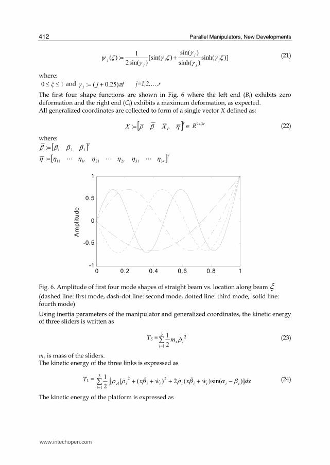
The first four shape functions are shown in Fig. 6 where the left end (Bi) exhibits zero
deformation and the right end (Ci) exhibits a maximum deformation, as expected. All generalized coordinates are collected to form of a single vector X defined as:
[ ]TPXX ηβρ=: rR 39+∈ (22)
where: [ ]T321: ββββ =
[ ]Trrr 331221111: ηηηηηηη AAA=
0 0.2 0.4 0.6 0.8 1-1
-0.5
0
0.5
1
Am
plitu
de
Fig. 6. Amplitude of first four mode shapes of straight beam vs. location along beam ξ
(dashed line: first mode, dash-dot line: second mode, dotted line: third mode, solid line: fourth mode)
Using inertia parameters of the manipulator and generalized coordinates, the kinetic energy of three sliders is written as
TS =∑=3
1
2
2
1
iism ρ$ (23)
ms is mass of the sliders. The kinetic energy of the three links is expressed as
TL = ∑ ∫=−++++3
1
22)]sin()(2)([
2
1
iiiiiiiiiA dxwxwx βαβρβρρ $$$$$$ (24)
The kinetic energy of the platform is expressed as
www.intechopen.com

Dynamic Modelling and Vibration Control of a Planar Parallel Manipulator with Structurally Flexible Linkages
413
TP = 222
2
1)(
2
1 φ$$$ PPPP Iyxm ++ (25)
mp , Ip are mass and mass moment of the platform respectively. Therefore, collecting all kinetic energies, equations (23-25), the total kinetic energy of the system is
T = ∑=3
1
2
2
1
iism ρ$ + ∑ ∫=
−++++3
1
22)]sin()(2)([
2
1
iiiiiiiiiA dxwxwx βαβρβρρ $$$$$
+ 222
2
1)(
2
1 φ$$$ PPPP Iyxm ++ (26)
Since gravitational force is applied along Z-direction, perpendicular to the X-Y plane, potential energy due to gravitational force does not changed at all during any in-plane motions of the manipulator. Considering potential energy due to deformation of the linkage, total potential energy of the system is given as
∑∫=′′= 3
1
2)(i
i dxwEIV (27)
where: Aρ := mass per length of the linkage
E := elastic modulus of the linkage I := area moment of inertia of the linkage Evaluating Lagrangian equations of the first type given by
∑= ∂∂+=∂
−∂−∂∂ m
k i
kki
ii X
ΓλQX
VT
X
T
dt
d
1
)()( $
, i=1,2,…, 9+3r (28)
where: iQ := generalized force
kλ := kth Lagrange multiplier
kΓ := kth constrained equation
the left-hand side of equation (28) is formulated as follows:
ii ρVT
ρT
dt
d
∂−∂−∂
∂ )()(
$=
iiiis ββαmlρmm $$$$ )sin(5.0)( −++ +∑ ∫=−r
j
jAiiij dxψρβαη1
)sin($$
∑ ∫=−−−− r
j
jAiiiijiii dxψρβαβηββαml1
2)cos()cos(5.0 $$$ i=1,2,3 (29)
iiβ
VT
βT
dt
d
∂−∂−∂
∂ )()( $
= ∑ ∫=++− r
j
jAijiiii dxψxρηβmlρβαml1
2 3/)sin(5.0 $$$$$$
+∑ ∫=−r
j
jAiiiij dxψρβαρη1
)cos($$ i=1,2,3 (30)
www.intechopen.com

Parallel Manipulators, New Developments
414
PP X
VT
X
T
dt
d
∂−∂−∂
∂ )()( $
=
⎥⎥⎥⎦
⎤⎢⎢⎢⎣
⎡⎥⎥⎥⎦
⎤⎢⎢⎢⎣
⎡φ$$$$$$
P
P
P
P
P
y
x
I
m
m
00
00
00 (31)
ijij ηVT
ηT
dt
d
∂−∂−∂
∂ )()(
$= dxψρηdxψxρβdxψρρβα jAijjAijAiii ∫ ∫∫ ++− 2
)sin( $$$$$$
- ∫ − iiiijA ρββαdxψρ $$)cos( + dxψEI j
2)(∫ ′′ i=1,2,3 and j=1,2,..,r (32)
m is mass of the linkage. Since the number of generalized coordinates excluding vibration modes is nine, greater than
the number of the degrees-of-freedom of the manipulator, three, six constraint equations
should be considered in equations of the motion. From the geometry of three closed-loop
chains, equation (4), a fundamental constrained equation is given by
0=−−+ iiiiii CBBACPPA i=1,2,3 (33)
Dividing equations (33) into an X-axis’s component and a Y-axis’s component, six constraint
equations are given by
12 −Γ i
:= )cos(sincoscos1
φφβηβαρ +−−−+ ∑= iP
r
jiijiii rxl = 0 (34)
i2Γ := )sin(cossinsin
1
φφβηβαρ +−−++ ∑= iP
r
iiijiii ryl = 0 (35)
where:
cii xr ′=:)cos(φ , cii yr ′=:)sin(φ i=1,2,3
From equation (34) and (35), the right-hand side of equation (28) is
iiiiai
i
k
kkai FF αλαλρλ sincos 212
6
1
++=∂Γ∂+ −=∑ i=1,2,3 (36)
)cossin(1
12
6
1
i
r
j
ijii
i
k
k
k βηβlλβΓλ ∑∑ =−=
−−=∂∂
)sincos(1
2 i
r
j
ijii βηβlλ ∑=−+ i=1,2,3 (37)
=∂∂+∑= P
k
k
kextX
ΓλF6
1 ⎥⎥⎥⎦
⎤⎢⎢⎢⎣
⎡⎥⎥⎥⎦
⎤⎢⎢⎢⎣
⎡−−−
−−−+
6
1
332211 333333
101010
010101
λλB
cscscs
Fext
(38)
where:
ixi es =:3 , iyi ec =:3
Fext is an external force and Fai is an actuating force.
www.intechopen.com

Dynamic Modelling and Vibration Control of a Planar Parallel Manipulator with Structurally Flexible Linkages
415
1211
1
6
1
cossin βλβληΓλ
j
k
k
k +−=∂∂∑= j=1,2,..,r (39)
2423
2
6
1
cossin βλβληΓλ
j
k
k
k +−=∂∂∑= j=1,2,..,r (40)
3635
3
6
1
cossin βλβληΓ
λj
k
k
k +−=∂∂∑= j=1,2,..,r (41)
Putting equations (29-32) and equations (36-41) together, the equations of motion for the
planar parallel manipulator are complete with a total of r×+ 39 equations;
⎥⎥⎥⎥
⎦
⎤
⎢⎢⎢⎢
⎣
⎡
⎥⎥⎥⎥
⎦
⎤
⎢⎢⎢⎢
⎣
⎡+
⎥⎥⎥⎥
⎦
⎤
⎢⎢⎢⎢
⎣
⎡+
⎥⎥⎥⎥
⎦
⎤
⎢⎢⎢⎢
⎣
⎡
⎥⎥⎥⎥
⎦
⎤
⎢⎢⎢⎢
⎣
⎡
ηX
βρ
KV
V
V
ηX
βρ
MMM
M
MMM
MMM
PP
TT
T
000
0000
0000
0000
0
0
000
0
0
4
2
1
442414
33
242212
141211
$$
$$$$$$
=
⎥⎥⎥⎥⎥⎥⎥⎥
⎦
⎤
⎢⎢⎢⎢⎢⎢⎢⎢
⎣
⎡
⎥⎥⎥⎥
⎦
⎤
⎢⎢⎢⎢
⎣
⎡+
⎥⎥⎥⎥
⎦
⎤
⎢⎢⎢⎢
⎣
⎡
ΓΓΓΓ
6
5
4
3
2
1
4
3
2
1
0
0
λλλλλλ
J
J
J
J
F
F
ext
a
(42)
where:
⎥⎥⎥⎦
⎤⎢⎢⎢⎣
⎡+=
100
010
001
)(11 mmM s
33×∈ R
⎥⎥⎥⎦
⎤⎢⎢⎢⎣
⎡=
3
2
1
12
00
00
00
2s
s
sml
M33×∈R
⎥⎥⎥⎥⎦
⎤
⎢⎢⎢⎢⎣
⎡=
∫∫∫∫∫∫ξdψsξdψs
ξdψsξdψs
ξdψsξdψs
mM
r
r
r
313
212
111
14
0000
0000
0000
AAAAAAAAA
rR 33×∈
⎥⎥⎥⎦
⎤⎢⎢⎢⎣
⎡=
100
010
001
3
2
22
mlM
33×∈ R
⎥⎥⎥⎦
⎤⎢⎢⎢⎣
⎡=
P
p
p
I
m
m
M
00
00
00
33
33×∈ R
⎥⎥⎥⎥⎦
⎤
⎢⎢⎢⎢⎣
⎡=
∫∫∫∫∫∫ξdξψξdξψ
ξdξψξdξψξdξψξdξψ
mlM
r
r
r
AAAAAAAAA
1
1
1
24
0000
0000
0000
rR 33×∈
www.intechopen.com

Parallel Manipulators, New Developments
416
⎥⎥⎥⎦
⎤⎢⎢⎢⎣
⎡=
M
M
M
mM
ˆ00
0ˆ0
00ˆ
44
rrR 33 ×∈
⎥⎥⎥⎦
⎤⎢⎢⎢⎣
⎡= ∫∫
ξdψ
ξdψM
r
2
2
1
0
0
ˆ
ABAB
ArrR ×∈
⎥⎥⎥⎦
⎤⎢⎢⎢⎣
⎡=
K
K
K
l
EIK
ˆ00
0ˆ0
00ˆ
3
rrR 33 ×∈⎥⎥⎥⎦
⎤⎢⎢⎢⎣
⎡′′
′′= ∫∫
ξdψ
ξdψK
r
2
2
1
0
0
ˆ
ABAB
A rrR ×∈
⎥⎥⎥⎥⎥⎥⎥
⎦
⎤
⎢⎢⎢⎢⎢⎢⎢
⎣
⎡
+++
−=∑ ∫∑ ∫∑ ∫
=
=
=
r
j
jj
r
j
jj
r
j
jj
ξdψcβηmβmlc
ξdψcβηmβmlc
ξdψcβηmβmlc
V
1
333
2
33
1
222
2
22
1
111
2
11
1
5.0
5.0
5.0
$$$
$$$
$$$
3R∈
⎥⎥⎥⎥⎥⎥⎥
⎦
⎤
⎢⎢⎢⎢⎢⎢⎢
⎣
⎡
=∑ ∫∑ ∫∑ ∫
=
=
=
r
j
jj
r
j
jj
r
j
jj
ξdψcρη
ξdψcρη
ξdψcρη
mV
1
333
1
222
1
111
2
$$
$$
$$3R∈
1 1 1 1
1 1 1
2 2 2 13
4
2 2 2
3 3 3 1
3 3 3
r
r
r
r
c d
c d
c d
V m R
c d
c d
c d
ρ β ψ ξρ β ψ ξρ β ψ ξρ β ψ ξρ β ψ ξρ β ψ ξ
⎡ ⎤∫⎢ ⎥⎢ ⎥⎢ ⎥∫⎢ ⎥∫⎢ ⎥⎢ ⎥= − ∈⎢ ⎥∫⎢ ⎥⎢ ⎥∫⎢ ⎥⎢ ⎥⎢ ⎥∫⎣ ⎦
$$B
$$$$B
$$$$B
$$
where : )sin(: iiis βα −= and )cos(: iiic βα −=
1 13 6
1 2 2
3 3
cos sin 0 0 0 0
0 0 cos sin 0 0
0 0 0 0 cos sin
J R
α α α α α α×Γ
⎡ ⎤⎢ ⎥= ∈⎢ ⎥⎢ ⎥⎣ ⎦
1 13 6
2 2 2
3 3
2 2 0 0 0 0
0 0 2 2 0 0
0 0 0 0 2 2
s c
J s c R
s c
×Γ⎡ ⎤⎢ ⎥= ∈⎢ ⎥⎢ ⎥⎣ ⎦
where: ∑=−−= r
j
ijiii ls1
cossin:2 ηββ and ∑=−= r
j
ijiii lc1
sincos:2 ηββ
www.intechopen.com

Dynamic Modelling and Vibration Control of a Planar Parallel Manipulator with Structurally Flexible Linkages
417
3 63
1 1 2 2 3 3
1 0 1 0 1 0
0 1 0 1 0 1
3 3 3 3 3 3
J R
s c s c s c
×Γ− − −⎡ ⎤⎢ ⎥= − − − ∈⎢ ⎥− − −⎢ ⎥⎣ ⎦
where: ixi es =:3 ,
iyi ec =:3
4. Active vibration control
If the intermediate linkages of the planar parallel manipulator are very stiff, an appropriate
rigid body model based controller, such as a computed torque controller (Craig, 2003), can
yield good trajectory tracking of the manipulator. However, structural flexibility of the
linkages transfers unwanted vibration to the platform, and may even lead to instability of
the whole system. Since control of linear motions of the sliders alone can not result in both
precise tracking of the platform and vibration attenuation of the linkages simultaneously, an
additional active damping method is proposed through the use of smart material. As
discussed, the vibration damping controller proposed here is applied separately to a PVDF
layer and PZT segments, and the performance of each actuator is then compared. Attached
to the surface of the linkage, both of these piezoelectric materials generate shear force under
applied control voltages, opposing shear stresses which arise due to elastic deformation of
the linkages.
The integrated control system for the planar parallel manipulator proposed here consists of
two components. The first component is a proportional and derivative (PD) feedback
control scheme for the rigid body tracking of the platform as given below:
)()()( idididiPi ρρkρρktu $$ −−−−= , i=1,2,3 (43)
where kp and kd are a proportional and a derivative feedback gain respectively. diρ and
diρ$
are desired displacement and velocity of the ith slider respectively. This signal is used as an
input to electrical motors actuating ball-screw mechanisms for sliding motions. In the
following, we introduce the second component of the integrated control system separately,
for each of the piezoelectric materials examined, a PVDF layer and PZT segments, shown
respectively in Fig. 7 and 8.
www.intechopen.com

Parallel Manipulators, New Developments
418
Fig. 7. Intermediate link with PVDF layer
Fig. 8. Intermediate link with PZT actuator
4.1 PVDF actuator control formulation
A PVDF layer can be bonded uniformly on the one side of the linkages of the planar parallel manipulator, as shown in Fig. 7. When a control voltage, vi, is applied to the PVDF layer, the virtual work done by the PVDF layer is expressed as
ij
r
j
jiPVDF )l()t(cvW δηψδ ∑= ′=1
(44)
where c is a constant representing the bending moment per volt (Bailey & Hubbard, 1985)
and l is the link length. ( )'⋅ implies differentiation with respect to x. If the control voltage
applied to the PVDF layer, vi , is formulated as
)t,l(wk)t(v iIi′−= $ i=1,2,3 (45)
the slope velocity of the linkages, )t,l(w′$ , converges to zero, assuming no exogenous
disturbances applied to the manipulator, hence vibration of the linkages is damped out. Since the slope velocity, )t,l(w′$ , is not easily measured or estimated by a conventional
sensor system, an alternative scheme, referred to as the L-type method (Sun & Mills, 1999), is proposed as follows:
)t,l(wk)t(v iIi$−= i=1,2,3 (46)
Instead of the slope velocity, )t,l(w′$ , the linear velocity, )t,l(w$ , is employed in formulation
of the control law. The linear velocity, )t,l(w$ , can be calculated through the integration of
www.intechopen.com

Dynamic Modelling and Vibration Control of a Planar Parallel Manipulator with Structurally Flexible Linkages
419
the linear acceleration measured by an accelerometer installed at the distal end of the linkages, Ci. The shape function, )(j 1=ξψ , and its derivative, )(j 1=′ ξψ , have same trend
of variation at the distal end of the linkages, Ci, in all vibration modes, as shown in Fig. 6 ;
011 ≥=′= )()( jj ξψξψ j=1,2,---,r (47)
Therefore, the control system maintains stability when employing the L-type method to formulate the control voltages, vi .
4.2 PZT actuator control formulation PZT actuators are manufactured in relatively small sizes, hence several PZT segments can be bonded together to a flexible linkage to damp unwanted vibrations. Assuming that only one PZT segment is attached to each intermediate linkage of the planar parallel manipulator, as shown in Fig. 8, the virtual work done by the PZT actuator is expressed as
ij
r
j
jjiPZT )]a()a([)t(cvW δηψψδ 1
1
2∑= ′−′= (48)
1a and 2a denote the positions of the two ends of the PZT actuator measured from Bi along
the intermediate linkage, as shown in Fig. 8. As the PVDF layer is, the PZT actuator is controlled using the L-type method as
)]t,a(w)t,a(w[k)t(v iiIi 12$$ −−= i=1,2,3 (49)
In contrast to the PVDF layer bonded uniformly to the manipulator linkages, the performance of the L-type scheme for the PZT actuator depends on the location of the PZT actuator. In order to achieve stable control performance, the PZT actuator should be placed in a region along the length of the linkage i.e. ],[ 21 aax∈ as discussed in (Sun & Mills, 1999),
where )(xψ j and )(xψ j
′ have the same trend of variation,
01212 ≥′−′− ))a()a())(a()a(( jjjj ψψψψ (50)
As the number of vibration modes increases, it is difficult to satisfy the stability condition, given in equation(50), for higher vibration modes, since the physical length of a PZT actuator is not sufficiently small.
5. Simulation results
Simulations are performed to investigate vibrations of the planar parallel manipulator linkages and damping performance of both piezoelectric actuators used in the manipulator with structurally-flexible linkages. Specifications of the manipulator for simulations are listed in Table 1. The first three modes are considered in the dynamic model, i.e. r=3. A sinusoidal function with smooth acceleration and deceleration is chosen as the desired input trajectory of the platform;
)2
sin(2
tt
ππ
xt
t
xx
f
f
f
f
P −= (51)
www.intechopen.com

Parallel Manipulators, New Developments
420
Considering the target-performance in an electrical assembly process, such as wire bonding
in integrated circuit fabrication, the goal for the platform is designed to move linearly 2 mm
(xf) within 10 msec (tf). Feedback gains of the control system for the slider actuators are listed
in Table 2. The feedback gain for piezoelectric actuators, kI, is selected so that the control
voltage, applied to the PVDF layer, does not exceed 600 Volts. A fourth order Runge-Kutta
method was used to integrate the ordinary differential equations, given by Equation (42) at a
control update rate of 1 msec, using MATLABTM software. Parameters of piezoelectric
materials, currently manufactured, are listed in Table 3. The placement position of the PZT
actuator is adjusted to a1=0.66, a2=0.91, so that the first two vibration modes satisfy the
stability condition given in equation (50).
Results of the PVDF layer are shown in Figures 9-12. Figure 9 shows that the error profile of
the manipulator platform exhibits large oscillation at the initial acceleration, but
continuously decreases due to the damping effect of the PVDF layer applied to the flexible
linkages. The error profile of the platform without either of PVDF or PZT, labeled as “no
damping” in Figure 9, shows typical characteristics of an undamped system. With Figure 10
showing deformation of the linkages on Ci, it reveals that the PVDF layer can damp
structural vibration of the linkages in a gradual way. The first three vibration modes are
illustrated in Figure 11. The first mode has twenty times the amplitude than the second
mode, and one hundred times the amplitude than the third mode. The control output for the
first slider actuator is shown in the upper plot of Figure 12, and control voltage for the first
PVDF layer is shown in the lower plot of Figure 12. The control voltage, applied to the
PVDF layer, decreases as the amplitude of vibration does.
Results of the PZT actuator are shown in Figures 13-17. Comparing Figure 13 with Figure 9,
the PZT actuator exhibits better damping performance than the PVDF layer. The error
profile of the platform, with the PZT actuator activated, enters steady state quickly and does
not exhibit any vibration in steady state. The structural vibrations of the linkages, illustrated
in Figure 14, are completely damped after 60 msec. The first three vibration modes are
shown in Figure 15. The first mode has ten times the amplitudes than the other modes. Since
the PZT actuator has higher strain constant than the PVDF, the PZT actuator can generate
large shear force with relatively small voltage applied. The maximum voltage of the lower
plot of Figure 16 is about 200 Volts, while that of the Figure 12 reaches 600 Volts. Due to the
length of the linkage and the PZT actuator applied to the linkage, only the first two modes
satisfy the stability condition, given by equation (50). However, this has little effect on
damping performance, as shown in Figure 14 since the first two modes play dominant roles
in vibration. If the placement of the PZT actuator change to a1=0.4, a2=0.65, only the first
mode satisfies the stability condition, which leads to divergence of vibration modes, as
shown in Figure 17.
6. Conclusion
In this chapter, the equations of motion for the planar parallel manipulator are formulated
by applying the Lagrangian equation of the first type. Introducing Lagrangian multipliers
simplifies the complexities due to multiple closed loop chains of the parallel mechanism and
the structurally flexible linkages. An active damping approach applied to two different
piezoelectric materials, which are used as actuators to damp unwanted vibrations of flexible
www.intechopen.com

Dynamic Modelling and Vibration Control of a Planar Parallel Manipulator with Structurally Flexible Linkages
421
linkages of a planar parallel manipulator. The proposed control is applied to PVDF layer
and PZT segments. An integrated control system, consisting of a PD feedback controller,
applied to electrical motors for rigid body motion control of the manipulator platform, and a
L-type controller applied to piezoelectric actuators to damp unwanted linkage vibrations, is
developed to permit the manipulator platform to follow a given trajectory while damping
vibration of the manipulator linkages. With an L-type control scheme determining a control
voltage applied, the piezoelectric materials have been shown to provide good damping
performance, and eventually reduce settling time of the platform of the planar parallel
manipulator. Simulation results show that the planar parallel manipulator, with the
lightweight linkages, during rigid body motion, undergoes persistent vibration due to high
acceleration and deceleration. Additionally, the PZT actuator yields better performance in
vibration attenuation than the PVDF layer, but may enter an unstable state if the position of
the PZT actuator on the linkage violates the stability condition for the dominant vibration
modes. In the near future, we will perform vibration experiments with a prototype planar
parallel manipulator based on presented simulation results.
Platform side length
mass 0.1 m 0.2 kg
Slider mass 0.2 kg
Linear guide (Ball-screw)
stroke incline angle
0.4 m 150o, 270 o, 30 o
Link
length density
modulus cross-section
0.2 m 2770 kg/m3
73 GPa 0.025 m(W) * 0.015 m(H)
Table 1. Specification of the planar parallel manipulator
kp 10,000 N/m
kd 500 N-sec/m
kI 4,000 V-sec/m for PVDF 1,500 V-sec/m for PZT
Table 2. Feedback control gains
PVDF PZT
modulus length
thickness width
density d31
2 GPa 0.2 m
0.28 mm 0.025 m
1800 kg/m3 22 * 10-12 m/V
63 GPa 0.05 m
0.75 mm 0.025 m
7600 kg/m3 110 * 10-12 m/V
Table 3. Parameters of piezoelectric materials
www.intechopen.com

Parallel Manipulators, New Developments
422
0 20 40 60 80 100-0.05
0
0.05
0.1
0.15
0.2
Error (mm)
Time (ms)
Fig. 9. Error profile of the platform (dotted: no damping, solid: with PVDF layer)
0 20 40 60 80 100-1
0
1
w1
(m
m)
0 20 40 60 80 100-1
0
1
w2
(m
m)
0 20 40 60 80 100-0.5
0
0.5
w3
(m
m)
Fig. 10. Flexible deformation of each link (dotted: no damping, solid: with PVDF layer)
0 20 40 60 80 100-1
0
1
1s
t M
od
e (
mm
)
0 20 40 60 80 100-0.05
0
0.05
2n
d M
od
e (
mm
)
0 20 40 60 80 100-0.01
0
0.01
3rd
Mo
de
(m
m)
Time (ms) Fig. 11. The first three vibration modes of the first link (dotted: no damping, solid: with PVDF layer)
Time (ms)
www.intechopen.com

Dynamic Modelling and Vibration Control of a Planar Parallel Manipulator with Structurally Flexible Linkages
423
0 20 40 60 80 100-100
-50
0
50
Force (N)
0 20 40 60 80 100-1000
-500
0
500
1000
Input Voltage for PVDF (Volts)
Time (ms)
Fig. 12. Control output for the first link
0 20 40 60 80 100-0.05
0
0.05
0.1
0.15
0.2
Error (mm)
Time (ms)
Fig. 13. Error profile of platform (dotted: no damping, solid: with PZT actuator)
0 20 40 60 80 100-1
0
1
w1
(m
m)
0 20 40 60 80 100-1
0
1
w2
(m
m)
0 20 40 60 80 100-0.5
0
0.5
w3
(m
m)
Fig. 14. Flexible deformation of each link (dotted: no damping, solid: with PZT actuator)
Time (ms)
www.intechopen.com

Parallel Manipulators, New Developments
424
0 20 40 60 80 100-1
0
1
1s
t M
od
e (
mm
)
0 20 40 60 80 100-0.1
0
0.1
2n
d M
od
e (
mm
)
0 20 40 60 80 100-0.05
0
0.05
3rd
Mo
de
(m
m)
Time (ms) Fig. 15. The first three vibration modes of the first link(dotted: no damping, solid: with PZT actuator)
0 20 40 60 80 100-100
-50
0
50
Force (N)
0 20 40 60 80 100-200
-100
0
100
200
Input Voltage for PZT (Volts)
Time (ms) Fig. 16. Control output for the first link
0 20 40 60 80 100-0.5
0
0.5
1s
t M
od
e (
mm
)
0 20 40 60 80 100-0.5
0
0.5
2n
d M
od
e (
mm
)
0 20 40 60 80 100-0.1
0
0.1
3rd
Mo
de
(m
m)
Time (ms)
Fig. 17. The first three vibration modes of the first link with PZT actuator located on inappropriate place
www.intechopen.com

Dynamic Modelling and Vibration Control of a Planar Parallel Manipulator with Structurally Flexible Linkages
425
7. References
Arai, T.; Cleary, K., Homma, K., Adachi, H., & Nakamura, T. (1991), Development of
parallel link manipulator for underground excavation task, Proceedings of
International Symposium on Advanced Robot Technology, pp. 541-548, Tokyo, Japan,
March 1991
Bailey, T. & Hubbard, J. (1985), Distributed piezoelectric-polymer active vibration control of
a cantilever beam, Journal of Guidance, Control and Dynamics, Vol. 8, No. 5, pp. 605-
611, 0731-5090
Bellezza, F.; Lanari, L. & Ulivi, G. (1990), Exact modeling of the flexible slewing link,
Proceedings of IEEE International Conference on Robotics and Automation, pp. 734-739,
0-8186-9061-5, Cincinnati, USA, May 1990, IEEE
Craig, J. J. (2003), Introduction to Robotics, Prentice-Hall, ISBN-10: 0387985069
Fattah, A.; Angeles, J. & Misra, K. A. (1995), Dynamic of a 3-DOF spatial parallel
manipulator with flexible links, Proceedings of IEEE International Conference on
Robotics and Automation, pp. 627-632, 0-7803-1965-6, Nagoya, Japan, May 1995, IEEE
Genta, G. (1993), Vibration of structures and machines, Springer, ISBN-10: 0387985069
Gosselin, C. & Angeles, J. (1990), Singularity analysis of closed-loop kinematic chains, IEEE
Transactions on Robotics and Automation, Vol. 6, No. 3, pp. 281-290, 1552-3098
Gosselin C.; Lemieux, S., & Merlet, J.-P. (1996), A new architecture of planar three- degree-
of-freedom parallel manipulator, Proceedings of IEEE International Conference on
Robotics and Automation, pp. 3738-3743, 0-7803-2988, Minneapolis, USA, April 1996,
IEEE
Heerah, I.; Kang, B., Mills, J. K., & Benhabib, B. (2002), Architecture selection and singularity
analysis of a 3-degree-of-freedom planar parallel manipulator, Proceedings of ASME
2002 Design Engineering Technical Conferences and Computers and Information in
Engineering Conference, pp. 1-6, 791836037, Montreal, Canada, October 2002, ASME
Kang, B.; Yeung, B., and Mills, J. K. (2002), Two-time scale controller design for a high speed
planar parallel manipulator with structural flexibility, Robotica, Vol. 20, No. 5, pp.
519-528, 0263-5747
Kozak, K.; Ebert-Uphoff, I., & Singhose, W. E. (2004), Locally linearized dynamic analysis of
parallel manipulators and application of input shaping to reduce vibrations, ASME
Journal of Mechanical Design, Vol. 126, No. 1, pp. 156-168, 1050-0472
Low, K. H. & Vidyasagar, M. (1988), A Lagrangian formulation of the dynamic model for
flexible manipulator systems, ASME Journal of Dynamic Systems, Measurement, and
Control, Vol. 110, pp. 175-181, 0022-0434
Merlet, J.-P. (1996), Direct kinematics of planar parallel manipulators, Proceedings of IEEE
International Conference on Robotics and Automation, pp. 3744-3749, 0-7803-2988,
Minneapolis, USA, April 1996, IEEE
Sun, D. & Mills, J. K. (1999), PZT actuator placement for structural vibration damping of
high speed manufacturing equipment, Proceedings of the American Control
Conference, pp. 1107-1111, 0780349903, San Diego, USA, June 1999, IEEE
www.intechopen.com

Parallel Manipulators, New Developments
426
Toyama, T.; Shibukawa, T., Hattori, K., Otubo, K., and Tsutsumi, M. (2001), Vibration
analysis of parallel mechanism platform with tilting linear motion actuators,
Journal of the Japan Society of Precision Engineering, Vol. 67, No. 9, pp. 458-1462, 0916-
78X
www.intechopen.com

Parallel Manipulators, New DevelopmentsEdited by Jee-Hwan Ryu
ISBN 978-3-902613-20-2Hard cover, 498 pagesPublisher I-Tech Education and PublishingPublished online 01, April, 2008Published in print edition April, 2008
InTech EuropeUniversity Campus STeP Ri Slavka Krautzeka 83/A 51000 Rijeka, Croatia Phone: +385 (51) 770 447 Fax: +385 (51) 686 166www.intechopen.com
InTech ChinaUnit 405, Office Block, Hotel Equatorial Shanghai No.65, Yan An Road (West), Shanghai, 200040, China
Phone: +86-21-62489820 Fax: +86-21-62489821
Parallel manipulators are characterized as having closed-loop kinematic chains. Compared to serialmanipulators, which have open-ended structure, parallel manipulators have many advantages in terms ofaccuracy, rigidity and ability to manipulate heavy loads. Therefore, they have been getting many attentions inastronomy to flight simulators and especially in machine-tool industries.The aim of this book is to provide anoverview of the state-of-art, to present new ideas, original results and practical experiences in parallelmanipulators. This book mainly introduces advanced kinematic and dynamic analysis methods and cuttingedge control technologies for parallel manipulators. Even though this book only contains several samples ofresearch activities on parallel manipulators, I believe this book can give an idea to the reader about what hasbeen done in the field recently, and what kind of open problems are in this area.
How to referenceIn order to correctly reference this scholarly work, feel free to copy and paste the following:
Bongsoo Kang and James K. Mills (2008). Dynamic Modelling and Vibration Control of a Planar ParallelManipulator with Structurally Flexible Linkages, Parallel Manipulators, New Developments, Jee-Hwan Ryu(Ed.), ISBN: 978-3-902613-20-2, InTech, Available from:http://www.intechopen.com/books/parallel_manipulators_new_developments/dynamic_modelling_and_vibration_control_of_a_planar_parallel_manipulator_with_structurally_flexible_

© 2008 The Author(s). Licensee IntechOpen. This chapter is distributedunder the terms of the Creative Commons Attribution-NonCommercial-ShareAlike-3.0 License, which permits use, distribution and reproduction fornon-commercial purposes, provided the original is properly cited andderivative works building on this content are distributed under the samelicense.


![Applied Mathematical Modelling - …download.xuebalib.com/xuebalib.com.35334.pdf · Applied Mathematical Modelling 40 (2016) ... ALDEP, CORELAP [19], and planar graph technique [16]](https://img.pdfslide.us/doc/110x75/5b8733fc7f8b9a3a608e6659/applied-mathematical-modelling-applied-mathematical-modelling-40-2016-.jpg)