Embed Size (px)
Citation preview
Solutions for Today | Options for Tomorrow
The 6th International Symposium – Supercritical CO2 Power Cycles
March 27-29, 2018, Pittsburgh, Pennsylvania
Dynamic Modeling of Microtube Recuperators in an Indirect Supercritical Carbon Dioxide Recompression Closed Brayton Power Cycle (+ recent PCHE results)Yuan Jianga, Eric A. Liesea, Stephen E. Zitneya,b and Debangsu Bhattacharyyab
a) National Energy Technology Laboratory, Morganton, WV; b) West Virginia University, Morgantown, WV
2
➢Introduction
➢Modeling Approach
• Tools, properties and thermal-hydraulic correlations
• Steady state optimal design
• Dynamic modeling
➢Results and Discussion
• Optimal designs using standard SS316 tubes
• Time constants and dynamic behaviors
• Comparison with other types of exchangers
➢Conclusion
Presentation Overview
3
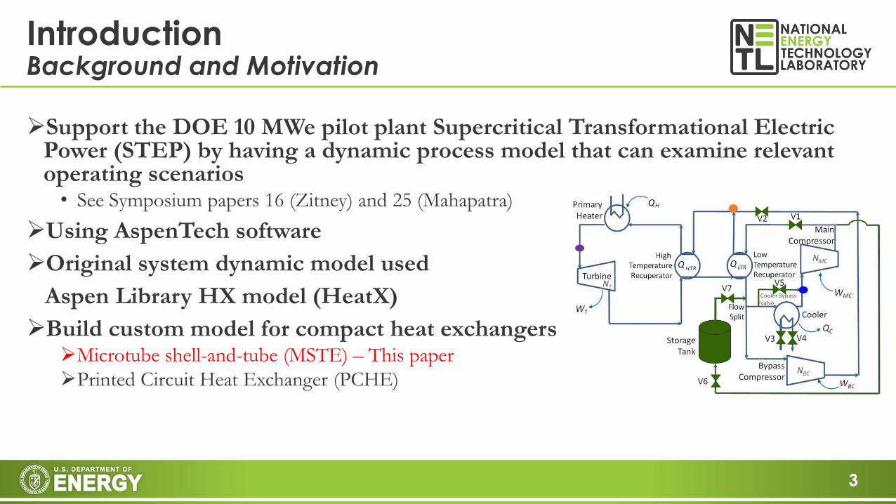
➢Support the DOE 10 MWe pilot plant Supercritical Transformational Electric Power (STEP) by having a dynamic process model that can examine relevant operating scenarios• See Symposium papers 16 (Zitney) and 25 (Mahapatra)
➢Using AspenTech software
➢Original system dynamic model used
Aspen Library HX model (HeatX)
➢Build custom model for compact heat exchangers➢Microtube shell-and-tube (MSTE) – This paper
➢Printed Circuit Heat Exchanger (PCHE)
IntroductionBackground and Motivation
4
IntroductionMicrotube shell-and-tube exchanger
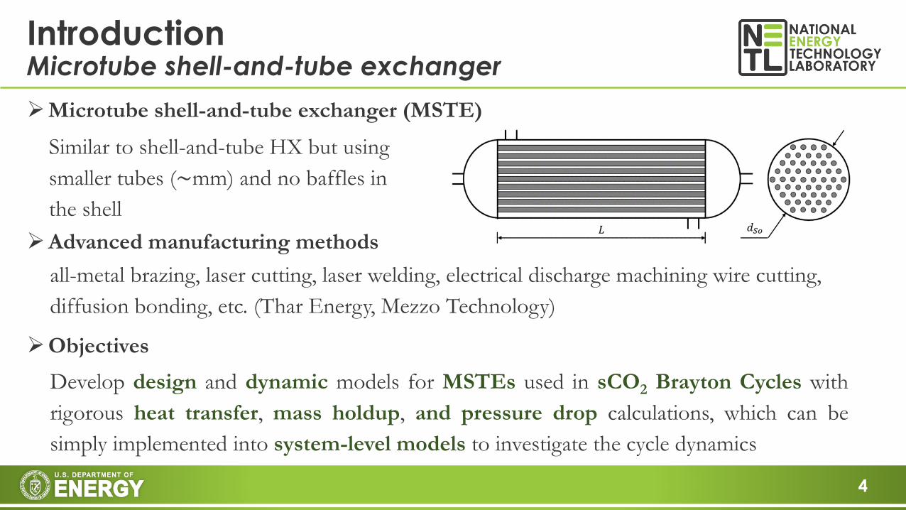
➢Objectives
Develop design and dynamic models for MSTEs used in sCO2 Brayton Cycles with
rigorous heat transfer, mass holdup, and pressure drop calculations, which can be
simply implemented into system-level models to investigate the cycle dynamics
➢Microtube shell-and-tube exchanger (MSTE)
➢Advanced manufacturing methods
Similar to shell-and-tube HX but using
smaller tubes (~mm) and no baffles in
the shell
all-metal brazing, laser cutting, laser welding, electrical discharge machining wire cutting,
diffusion bonding, etc. (Thar Energy, Mezzo Technology)
5
Modeling ApproachTools, properties and thermal-hydraulic correlations
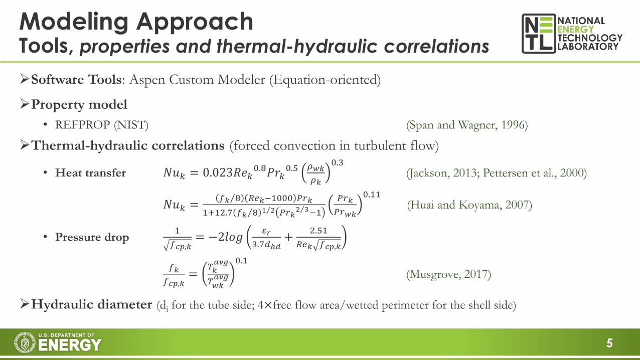
➢Software Tools: Aspen Custom Modeler (Equation-oriented)
➢Property model
• REFPROP (NIST) (Span and Wagner, 1996)
➢Thermal-hydraulic correlations (forced convection in turbulent flow)
• Heat transfer 𝑁𝑢𝑘 = 0.023𝑅𝑒𝑘0.8𝑃𝑟𝑘
0.5 𝜌𝑤𝑘
𝜌𝑘
0.3(Jackson, 2013; Pettersen et al., 2000)
𝑁𝑢𝑘 =Τ𝑓𝑘 8 𝑅𝑒𝑘−1000 𝑃𝑟𝑘
1+12.7 Τ𝑓𝑘 8 Τ1 2 𝑃𝑟𝑘Τ2 3−1
𝑃𝑟𝑘
𝑃𝑟𝑤𝑘
0.11(Huai and Koyama, 2007)
• Pressure drop1
𝑓𝑐𝑝,𝑘= −2𝑙𝑜𝑔
𝜀𝑟
3.7𝑑ℎ𝑑+
2.51
𝑅𝑒𝑘 𝑓𝑐𝑝,𝑘
𝑓𝑘
𝑓𝑐𝑝,𝑘=
𝑇𝑘𝑎𝑣𝑔
𝑇𝑤𝑘𝑎𝑣𝑔
0.1
(Musgrove, 2017)
➢Hydraulic diameter (di for the tube side; 4×free flow area/wetted perimeter for the shell side)
6
Modeling ApproachOptimal designs in Aspen Custom Modeler (Jiang, et al.)
Cold in
Hot in
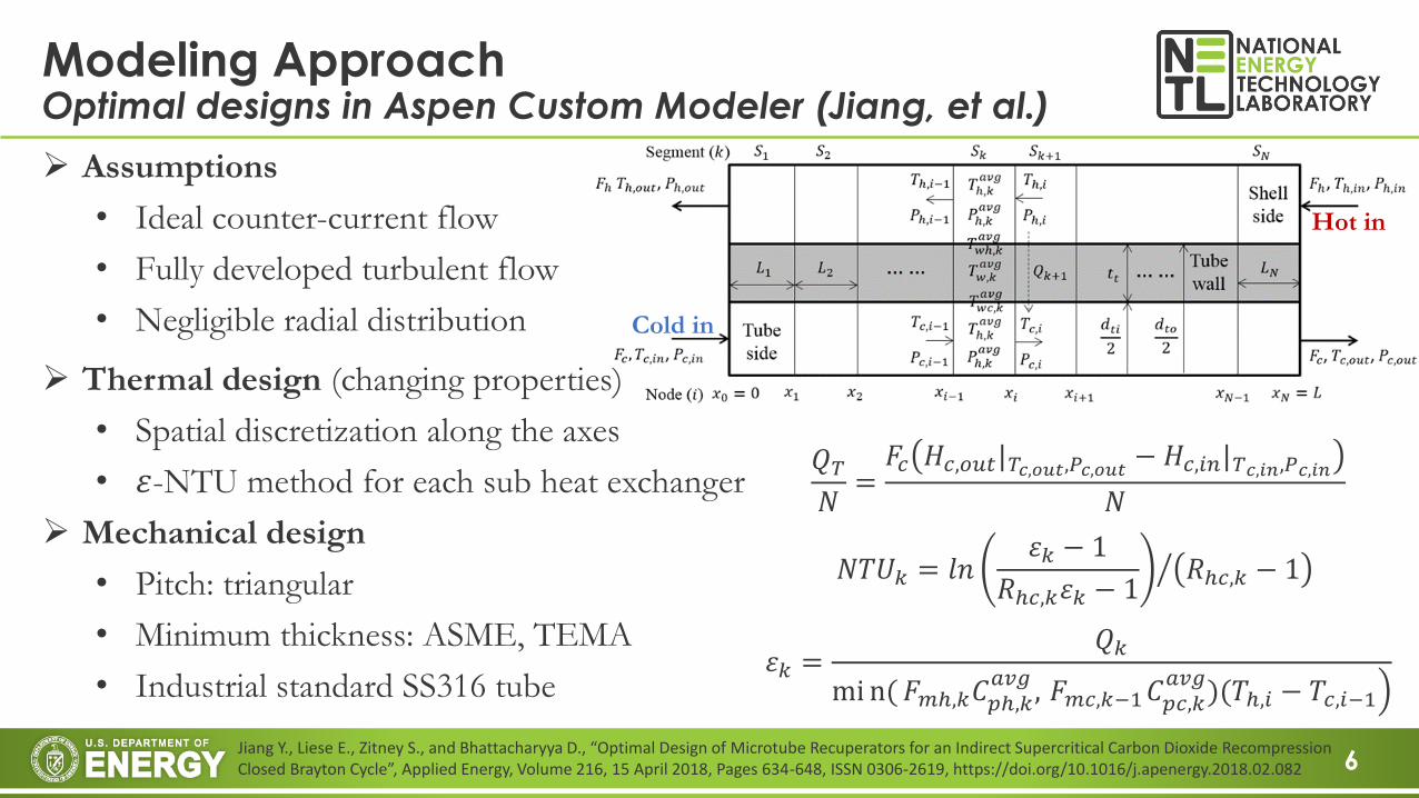
➢ Thermal design (changing properties)
• Spatial discretization along the axes
• 𝜀-NTU method for each sub heat exchanger
➢ Mechanical design
• Pitch: triangular
• Minimum thickness: ASME, TEMA
• Industrial standard SS316 tube
➢ Assumptions
• Ideal counter-current flow
• Fully developed turbulent flow
• Negligible radial distribution
𝑁𝑇𝑈𝑘 = ൗ𝑙𝑛𝜀𝑘 − 1
𝑅ℎ𝑐,𝑘𝜀𝑘 − 1𝑅ℎ𝑐,𝑘 − 1
𝑄𝑇𝑁
=𝐹𝑐 𝐻𝑐,𝑜𝑢𝑡|𝑇𝑐,𝑜𝑢𝑡,𝑃𝑐,𝑜𝑢𝑡 − 𝐻𝑐,𝑖𝑛|𝑇𝑐,𝑖𝑛,𝑃𝑐,𝑖𝑛
𝑁
𝜀𝑘 =𝑄𝑘
ቁmi n(𝐹𝑚ℎ,𝑘𝐶𝑝ℎ,𝑘𝑎𝑣𝑔
, 𝐹𝑚𝑐,𝑘−1𝐶𝑝𝑐,𝑘𝑎𝑣𝑔
)(𝑇ℎ,𝑖 − 𝑇𝑐,𝑖−1
Jiang Y., Liese E., Zitney S., and Bhattacharyya D., “Optimal Design of Microtube Recuperators for an Indirect Supercritical Carbon Dioxide Recompression Closed Brayton Cycle”, Applied Energy, Volume 216, 15 April 2018, Pages 634-648, ISSN 0306-2619, https://doi.org/10.1016/j.apenergy.2018.02.082
7
Modeling ApproachOptimal designs in Aspen Custom Modeler
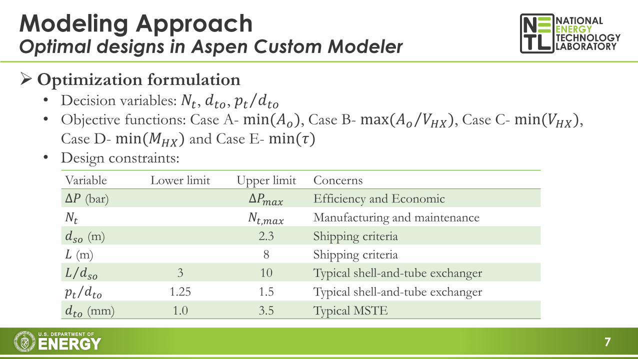
Variable Lower limit Upper limit Concerns
∆𝑃 (bar) ∆𝑃𝑚𝑎𝑥 Efficiency and Economic
𝑁𝑡 𝑁𝑡,𝑚𝑎𝑥 Manufacturing and maintenance
𝑑𝑠𝑜 (m) 2.3 Shipping criteria
𝐿 (m) 8 Shipping criteria
Τ𝐿 𝑑𝑠𝑜 3 10 Typical shell-and-tube exchanger
Τ𝑝𝑡 𝑑𝑡𝑜 1.25 1.5 Typical shell-and-tube exchanger
𝑑𝑡𝑜 (mm) 1.0 3.5 Typical MSTE
➢Optimization formulation• Decision variables: 𝑁𝑡, 𝑑𝑡𝑜, Τ𝑝𝑡 𝑑𝑡𝑜• Objective functions: Case A- min(𝐴𝑜), Case B- max( Τ𝐴𝑜 𝑉𝐻𝑋), Case C- min(𝑉𝐻𝑋),
Case D- min(𝑀𝐻𝑋) and Case E- min(𝜏)• Design constraints:
8
Modeling ApproachDynamic modeling in Aspen Custom Modeler
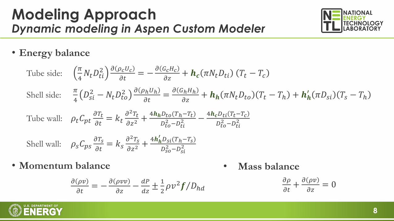
• Energy balance
Tube side:𝜋
4𝑁𝑡𝐷𝑡𝑖
2 𝜕 𝜌𝑐𝑈𝑐
𝜕𝑡= −
𝜕 𝐺𝑐𝐻𝑐
𝜕𝑧+ 𝒉𝒄 𝜋𝑁𝑡𝐷𝑡𝑖 𝑇𝑡 − 𝑇𝑐
Shell side:𝜋
4𝐷𝑠𝑖2 −𝑁𝑡𝐷𝑡𝑜
2 𝜕 𝜌ℎ𝑈ℎ
𝜕𝑡=
𝜕 𝐺ℎ𝐻ℎ
𝜕𝑧+ 𝒉𝒉 𝜋𝑁𝑡𝐷𝑡𝑜 𝑇𝑡 − 𝑇ℎ + 𝒉𝒉
′ 𝜋𝐷𝑠𝑖 𝑇𝑠 − 𝑇ℎ
Tube wall: 𝜌𝑡𝐶𝑝𝑡𝜕𝑇𝑡
𝜕𝑡= 𝑘𝑡
𝜕2𝑇𝑡
𝜕𝑧2+
4𝒉𝒉𝐷𝑡𝑜(𝑇ℎ−𝑇𝑡)
𝐷𝑡𝑜2 −𝐷𝑡𝑖
2 −4𝒉𝒄𝐷𝑡𝑖 𝑇𝑡−𝑇𝑐
𝐷𝑡𝑜2 −𝐷𝑡𝑖
2
Shell wall: 𝜌𝑠𝐶𝑝𝑠𝜕𝑇𝑠
𝜕𝑡= 𝑘𝑠
𝜕2𝑇𝑠
𝜕𝑧2+
4𝒉𝒉′ 𝐷𝑠𝑖(𝑇ℎ−𝑇𝑠)
𝐷𝑠𝑜2 −𝐷𝑠𝑖
2
• Momentum balance
𝜕 𝜌𝑣
𝜕𝑡= −
𝜕 𝜌𝑣𝑣
𝜕𝑧−
𝑑𝑃
𝑑𝑧±
1
2Τ𝜌𝑣2𝒇 𝐷ℎ𝑑
• Mass balance
𝜕𝜌
𝜕𝑡+
𝜕 𝜌𝑣
𝜕𝑧= 0
9
• Introduction
• Modeling Approach
• Tools, properties and thermal-hydraulic correlations
• Steady state optimal design
• Dynamic modeling
• Results and Discussion
• Optimal designs using standard SS316 tubes
• Time constants and dynamic behaviors
• Comparison with other types of exchangers
• Conclusion
Presentation Overview
10
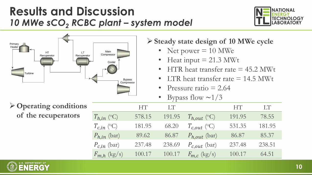
Results and Discussion10 MWe sCO2 RCBC plant – system model
HT LT HT LT
𝑇ℎ,𝑖𝑛 (oC) 578.15 191.95 𝑇ℎ,𝑜𝑢𝑡 (oC) 191.95 78.55
𝑇𝑐,𝑖𝑛 (oC) 181.95 68.20 𝑇𝑐,𝑜𝑢𝑡 (oC) 531.35 181.95
𝑃ℎ,𝑖𝑛 (bar) 89.62 86.87 𝑃ℎ,𝑜𝑢𝑡 (bar) 86.87 85.37
𝑃𝑐,𝑖𝑛 (bar) 237.48 238.69 𝑃𝑐,𝑜𝑢𝑡 (bar) 237.48 238.51
𝐹𝑚,ℎ (kg/s) 100.17 100.17 𝐹𝑚,𝑐 (kg/s) 100.17 64.51
➢Operating conditions
of the recuperators
➢Steady state design of 10 MWe cycle
• Net power = 10 MWe
• Heat input = 21.3 MWt
• HTR heat transfer rate = 45.2 MWt
• LTR heat transfer rate = 14.5 MWt
• Pressure ratio = 2.64
• Bypass flow ~1/3
11
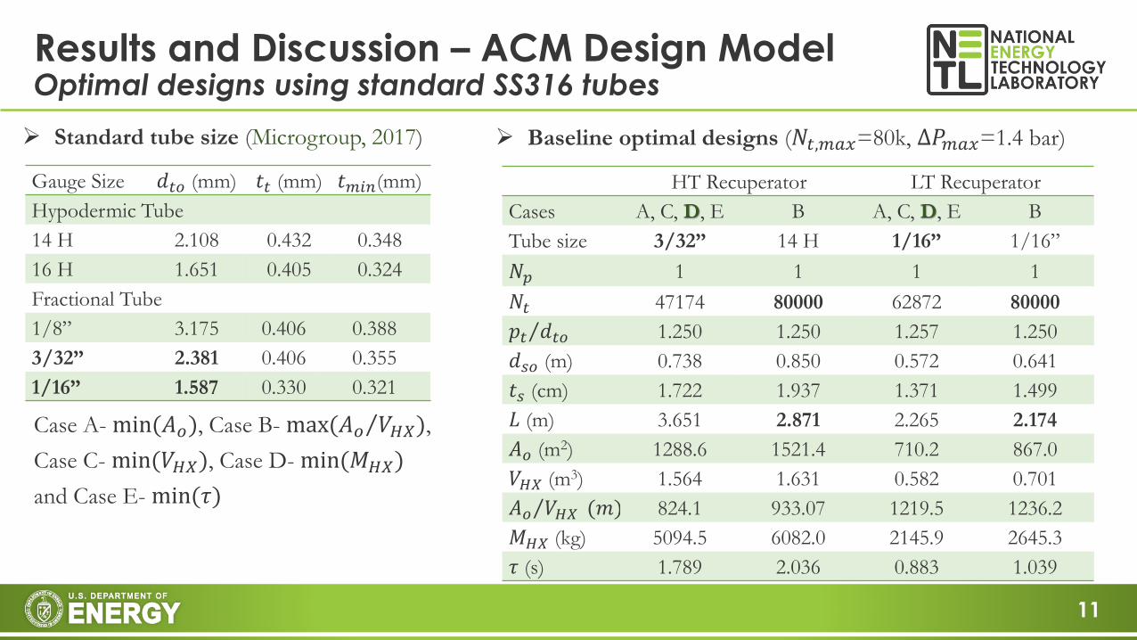
Results and Discussion – ACM Design ModelOptimal designs using standard SS316 tubes
➢ Standard tube size (Microgroup, 2017)
Gauge Size 𝑑𝑡𝑜 (mm) 𝑡𝑡 (mm) 𝑡𝑚𝑖𝑛(mm)
Hypodermic Tube
14 H 2.108 0.432 0.348
16 H 1.651 0.405 0.324
Fractional Tube
1/8” 3.175 0.406 0.388
3/32” 2.381 0.406 0.355
1/16” 1.587 0.330 0.321
HT Recuperator LT Recuperator
Cases A, C, D, E B A, C, D, E B
Tube size 3/32” 14 H 1/16” 1/16”
𝑁𝑝 1 1 1 1
𝑁𝑡 47174 80000 62872 80000
Τ𝑝𝑡 𝑑𝑡𝑜 1.250 1.250 1.257 1.250
𝑑𝑠𝑜 (m) 0.738 0.850 0.572 0.641
𝑡𝑠 (cm) 1.722 1.937 1.371 1.499
𝐿 (m) 3.651 2.871 2.265 2.174
𝐴𝑜 (m2) 1288.6 1521.4 710.2 867.0
𝑉𝐻𝑋 (m3) 1.564 1.631 0.582 0.701
Τ𝐴𝑜 𝑉𝐻𝑋 (𝑚) 824.1 933.07 1219.5 1236.2
𝑀𝐻𝑋 (kg) 5094.5 6082.0 2145.9 2645.3
𝜏 (s) 1.789 2.036 0.883 1.039
➢ Baseline optimal designs (𝑁𝑡,𝑚𝑎𝑥=80k, ∆𝑃𝑚𝑎𝑥=1.4 bar)
Case A- min(𝐴𝑜), Case B- max( Τ𝐴𝑜 𝑉𝐻𝑋),
Case C- min(𝑉𝐻𝑋), Case D- min(𝑀𝐻𝑋)
and Case E- min(𝜏)
12
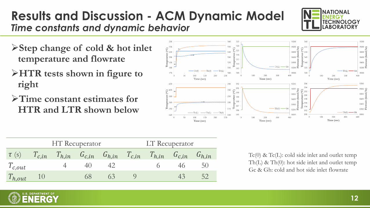
➢Step change of cold & hot inlet temperature and flowrate
➢HTR tests shown in figure to right
➢Time constant estimates for HTR and LTR shown below
Results and Discussion - ACM Dynamic ModelTime constants and dynamic behavior
HT Recuperator LT Recuperator
𝜏 (s) 𝑇𝑐,𝑖𝑛 𝑇ℎ,𝑖𝑛 𝐺𝑐,𝑖𝑛 𝐺ℎ,𝑖𝑛 𝑇𝑐,𝑖𝑛 𝑇ℎ,𝑖𝑛 𝐺𝑐,𝑖𝑛 𝐺ℎ,𝑖𝑛𝑇𝑐,𝑜𝑢𝑡 4 40 42 6 46 50
𝑇ℎ,𝑜𝑢𝑡 10 68 63 9 43 52
Tc(0) & Tc(L): cold side inlet and outlet temp
Th(L) & Th(0): hot side inlet and outlet temp
Gc & Gh: cold and hot side inlet flowrate
13
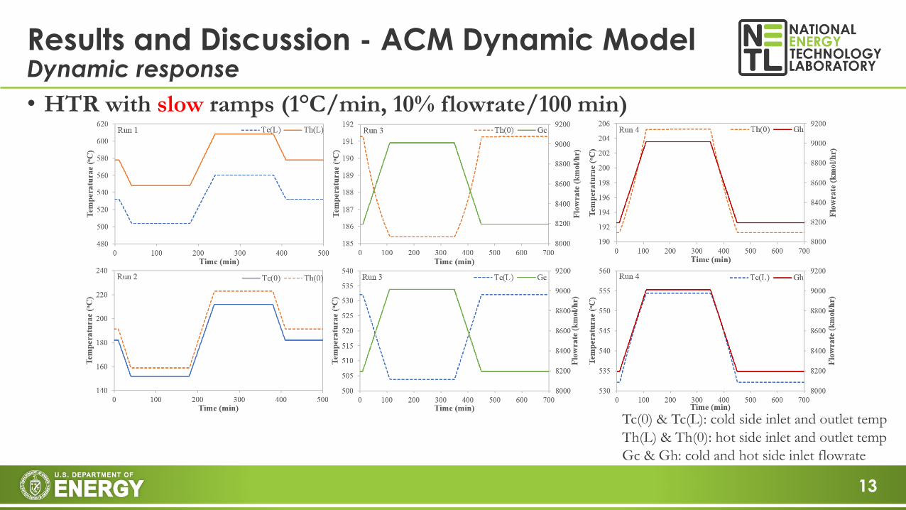
Results and Discussion - ACM Dynamic ModelDynamic response
• HTR with slow ramps (1°C/min, 10% flowrate/100 min)
Tc(0) & Tc(L): cold side inlet and outlet temp
Th(L) & Th(0): hot side inlet and outlet temp
Gc & Gh: cold and hot side inlet flowrate
14
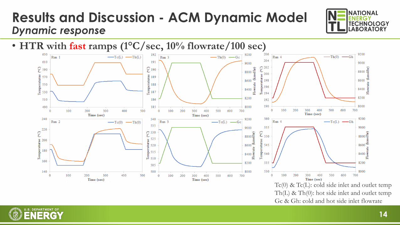
Results and Discussion - ACM Dynamic ModelDynamic response
• HTR with fast ramps (1°C/sec, 10% flowrate/100 sec)
Tc(0) & Tc(L): cold side inlet and outlet temp
Th(L) & Th(0): hot side inlet and outlet temp
Gc & Gh: cold and hot side inlet flowrate
15
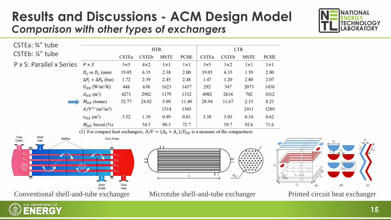
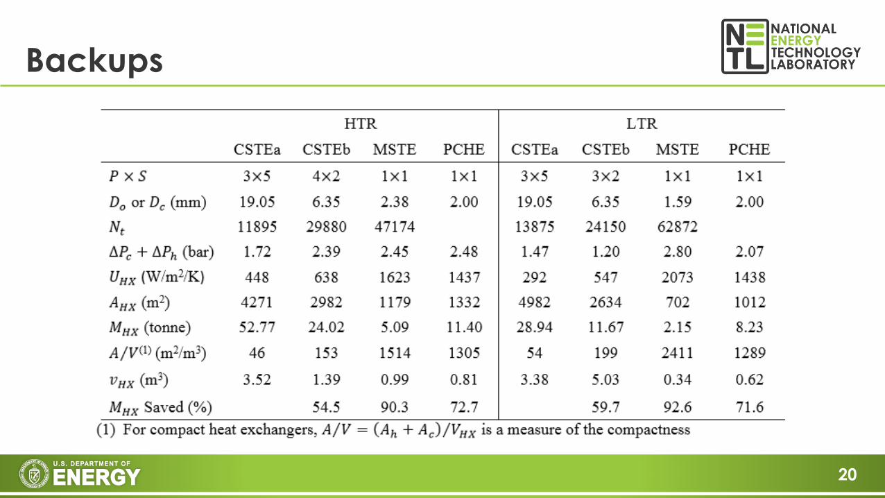
Results and Discussions - ACM Design ModelComparison with other types of exchangers
Conventional shell-and-tube exchanger Microtube shell-and-tube exchanger Printed circuit heat exchanger
CSTEa: ¾” tubeCSTEb: ¼” tube
P x S: Parallel x Series
16
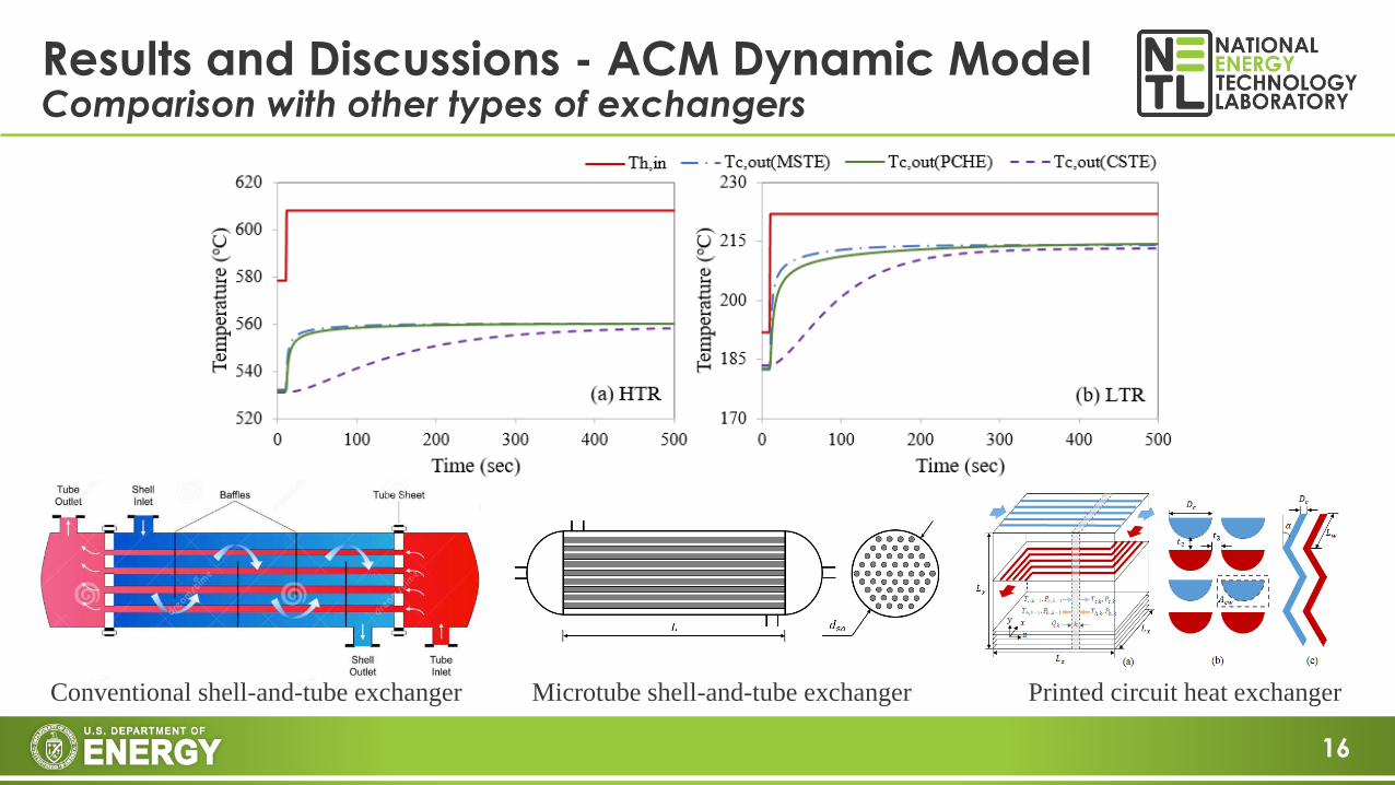
Results and Discussions - ACM Dynamic ModelComparison with other types of exchangers
Conventional shell-and-tube exchanger Microtube shell-and-tube exchanger Printed circuit heat exchanger
17
• Steady-state design and dynamic models were developed in Aspen Custom Modeler (ACM) for microtube shell-and-tube exchangers in a 10MWe indirect sCO2 RCBC plant. The ACM design model sets up the sizing for the dynamic model.
• The Aspen Custom dynamic models have been incorporated into the 10 MW model for the HTR and LTR.
• The microtube shell-and-tube exchangers have relatively fast dynamic behavior because of lower metal mass and higher heat transfer coefficients
Conclusion
18
• This project was supported in part by an appointment to the Science Education Programs at National Energy Technology Laboratory (NETL), administrated by ORAU through the U.S. Department of Energy Oak Ridge Institute for Science and Education (ORISE).
Acknowledgements

19
Thank you!
Comments/Questions?
Disclaimer: This presentation was prepared as an account of work sponsored by an agency of the United States
Government. Neither the United States Government nor any agency thereof, nor any of their employees, makes any
warranty, express or implied, or assumes any legal liability or responsibility for the accuracy, completeness, or usefulness
of any information, apparatus, product, or process disclosed, or represents that its use would not infringe privately owned
rights. Reference herein to any specific commercial product, process, or service by trade name, trademark, manufacturer,
or otherwise does not necessarily constitute or imply its endorsement, recommendation, or favoring by the United States
Government or any agency thereof. The views and opinions of authors expressed herein do not necessarily state or reflect
those of the United States Government or any agency thereof.
20
Backups


![[G] - CENTRIFUGES 8 12* 2 2 2 2 2 4 12 24 24 24 4 Microtube 1,5 / 2 mL Microtube 0,5 mL Microtube 0,2 mL PCR strips 0,2 mL Microhematocrit Capillary Description Microplates Capacity](https://img.pdfslide.us/doc/110x75/5f187988aaf54a03643ad1c8/g-centrifuges-8-12-2-2-2-2-2-4-12-24-24-24-4-microtube-15-2-ml-microtube.jpg)