Embed Size (px)
Citation preview
The 7th Jordanian International Mechanical Engineering Conference (JIMEC’7) 27 - 29 September 2010, Amman – Jordan
DYNAMIC MODELING AND CONTROL OF ELASTIC BEAM FIXED ON A
MOVING CART AND CARRYING LUMPED TIP MASS
Fadi A. Ghaith, [email protected] Department of Mechanical Engineering, King Fahd
University of Petroleum and Minerals, Dhahran, Saudi Arabia.
Mohammad N. Hamdan, [email protected] Department of Mechanical Engineering ,University of
Jordan, Amman, Jordan.
ABSTRACT
In this paper, a Bernoulli – Euler beam fixed on a moving cart and carrying a lumped tip mass is
considered. The equations of motion which describe the global motion as well as the vibrational
motion were derived using the extended Hamilton’s principle. The obtained equations of motion are
analyzed by means of the unconstrained modal analysis. In order to eliminate the need of sensor
placement at the tip of the cantilever beam, as most of the practical control implementations require
that sensors and actuators to be placed in accessible locations, the Linear Quadratic Estimator (LQE)
approach was utilized to estimate the vibrations of any point on the span of the elastic cantilever beam
in the presence of process and measurement noises. For the purpose of suppressing the vibrations at
the tip of the beam, an active optimal controller was designed based on the Linear Quadratic Gaussian
(LQG) method. Numerical simulation results demonstrated the capability of the developed optimal
controller in eliminating the vibrations at the tip of the beam as well as to improve the positioning
accuracy.
Keywords: Unconstrained modal analysis, Linear quadratic estimator, Linear quadratic Gaussian.
1. INTRODUCTION
The beam is considered as one of the fundamental elements of an engineering structure. It finds use in
varied structural applications. Moreover, structures like forklift vehicles or ladder cars that carry heavy
loads, military airplane wings with storage loads on their span and antenna operated in the space can
be modeled as a flexible beam carrying a concentrated mass and being fixed on a moving cart. Due to
the presence of vibration in such systems, it leads to undesirable effects such as structural and
mechanical failures, though vibration suppression has been main requirement for their design and safe
operation. Active control falls among the most feasible techniques for vibration suppression in axially
moving structures, where passive techniques may become ineffective or impractical. On the other side,
unconstrained modal analysis is considered as a powerful tool to generate accurate mode shapes of the
The 7th Jordanian International Mechanical Engineering Conference (JIMEC’7) 27 - 29 September 2010, Amman – Jordan
system, such analysis may provide useful information which may enhance the design of the optimal
controller. Many studies were reported in the literature concerned of the mathematical modeling of
similar systems based on the linear formulation. Exact frequency equation of a uniform cantilever
beam carrying a slender tip mass whose center of gravity didn't coincide with the attachment point has
been developed by [Bhat and Wanger, 1979]. [To, 1982] calculated the natural frequencies and mode
shapes of a mast antenna structure, but he modeled it as a cantilever beam with base excitation and tip
mass because the total mass of the beam-mass system is negligible compared with that to the base.
[Park et al., 1998] obtained the linear equations of motion, frequency equations and exact solutions of
the motion of flexible beam fixed on a moving cart and carrying a lumped tip mass using
unconstrained modal analysis. [Park et al., 2000] considered a Bernoulli-Euler beam fixed on a
moving cart and carrying a concentrated mass attached at an arbitrary position along the beam, and the
linear equations of motion which describe the global motion as well as vibrations motion were
derived. Vibration suppression has been a requirement for the design and operations in many
engineering structures. Due to the development in the area of control systems, active controllers have
been implemented in several vibration suppression applications. [Khulief, 2000] has proposed the
control of a rotating beam mounted on a rigid hub using linear quadratic regulator. [Zimmerman and
Cudeney, 1989], [Yousfi-Koma and Vukovich, 2000], [Mallory and Miller, 2000], [Lee and Eillott,
2001], all have also suggested placing sensors at various locations along the span of the beam for
monitoring and control purposes. [Sinawi and Hamdan, 2003] developed a new approach for
estimating the vibration of any point on the span of a rotating flexible beam mounted on a compliant
hub (plant) in the presence of process and measurements noise based on the Linear Quadratic
Estimator (LQE) technique. At this point one can conclude that an active control law that uses a
consistent dynamic model and utilizes the linear quadratic regulator in absence of process and
measurement noise is not fully addressed, in particular when unconstrained modal analysis is utilized
as the modeling tool. In this paper, the equations of motion of a Bernoulli-Euler cantilever beam
clamped on a moving cart and carrying lumped mass are analyzed by means of the unconstrained
modal analysis, and a unified characteristic equation for calculating the natural frequencies of the
system. The natural frequencies obtained from the unconstrained modal analysis are used to develop
an active modal controller based on Kalman filter estimator and linear quadratic regulator in order to
reduce the end vibration as well as to improve the positioning accuracy.
2. MODEL FORMULATION
The equations of motion of a Bernoulli-Euler cantilever beam clamped on a moving cart and carrying
lumped mass on its tip are derived using the extended Hamilton's principle. It should be recognized
The 7th Jordanian International Mechanical Engineering Conference (JIMEC’7) 27 - 29 September 2010, Amman – Jordan
that the addressed dynamic model is considered to be linear by neglecting the effect of axial
shortening.
2.1 System Description and Assumptions
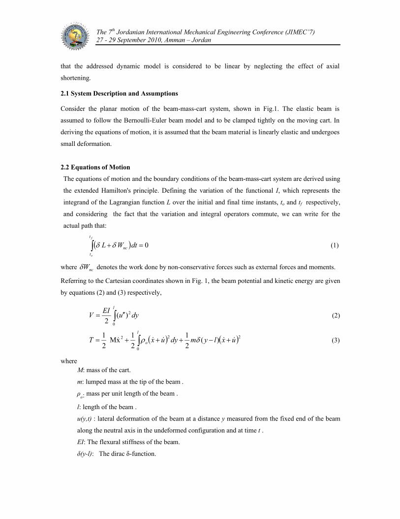
Consider the planar motion of the beam-mass-cart system, shown in Fig.1. The elastic beam is
assumed to follow the Bernoulli-Euler beam model and to be clamped tightly on the moving cart. In
deriving the equations of motion, it is assumed that the beam material is linearly elastic and undergoes
small deformation.
2.2 Equations of Motion
The equations of motion and the boundary conditions of the beam-mass-cart system are derived using
the extended Hamilton's principle. Defining the variation of the functional I, which represents the
integrand of the Lagrangian function L over the initial and final time instants, to and tf respectively,
and considering the fact that the variation and integral operators commute, we can write for the
actual path that:
0 dtWLf
o
t
t
nc (1)
where ncW denotes the work done by non-conservative forces such as external forces and moments.
Referring to the Cartesian coordinates shown in Fig. 1, the beam potential and kinetic energy are given
by equations (2) and (3) respectively,
l
dyuEI
V0
2)(2
(2)
22
0
2 )(2
1
2
1xM
2
1uxlymdyuxT
l
o (3)
whereM: mass of the cart.
m: lumped mass at the tip of the beam .
ρo: mass per unit length of the beam .
l: length of the beam .
u(y,t) : lateral deformation of the beam at a distance y measured from the fixed end of the beam
along the neutral axis in the undeformed configuration and at time t .
EI: The flexural stiffness of the beam.
δ(y-l): The dirac δ-function.
The 7th Jordanian International Mechanical Engineering Conference (JIMEC’7) 27 - 29 September 2010, Amman – Jordan
Fig. 1: Schematic of the beam-mass-cart system.
Substituting equations (2) and (3) into equation (1), noting that VTL , and after some
mathematical manipulations including integration by parts, yields
)()(0
tFdyuxlymxMl
o (4)
0)()( uxlymuEI o (5)
0),(,0),(,0),0(,0),0( tluEItluEItutu (6)
3. MODAL ANALYSIS
In this study, the obtained equations of motion are analyzed utilizing the unconstrained modal analysis
which admits the presence of the external forcing terms. Assuming that the position of the cart x(t) has
a solution of the form:
)()()( tqttx (7)
where α(t) describes the motion of the center of mass . Therefore, the motion of the center of the mass
without perturbation can be expressed as:
)()( tFtMt (8)
where Mtis the total mass of the beam-mass-cart system such bt mmMM and m
brepresents
the mass of the flexible beam such lm ob .
Also, the deflection of the beam u(y,t) is assumed to have the solution of the form
)()(),( tqytyu (9)
Defining )()( yy , and substituting equations (7) and (9) into equation (5), one obtains
0)()()()()()( ttqylymtqyEI o (10)
The 7th Jordanian International Mechanical Engineering Conference (JIMEC’7) 27 - 29 September 2010, Amman – Jordan
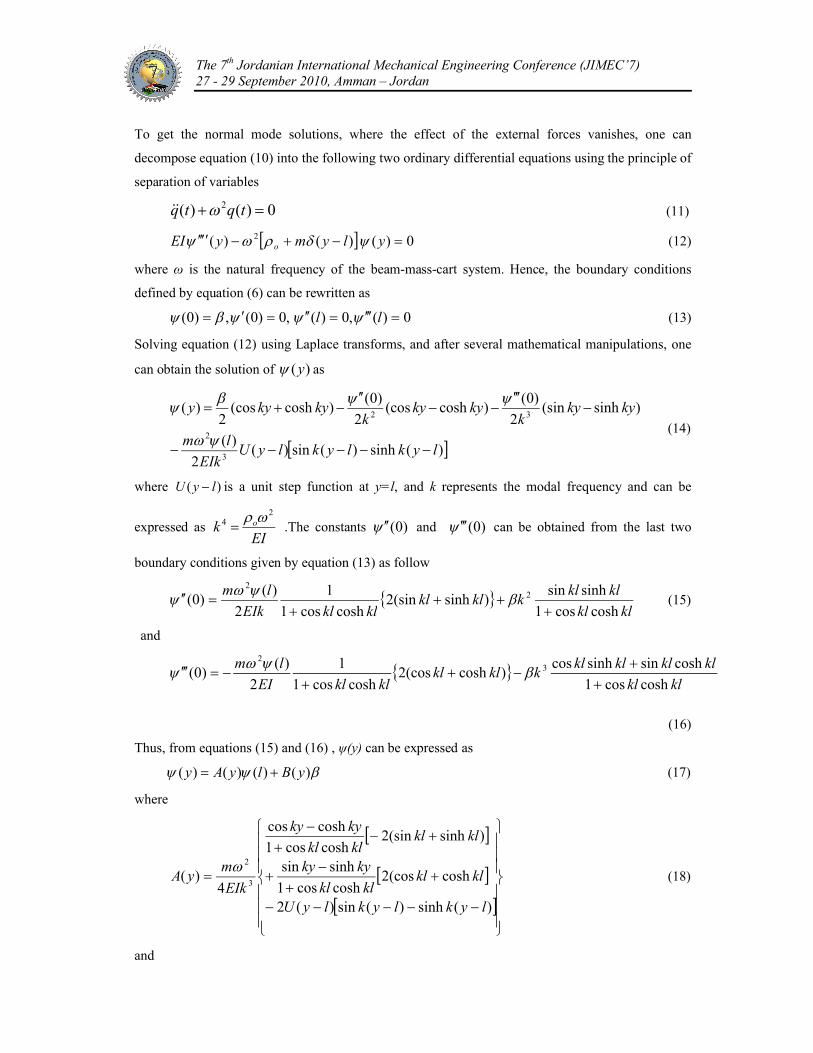
To get the normal mode solutions, where the effect of the external forces vanishes, one can
decompose equation (10) into the following two ordinary differential equations using the principle of
separation of variables
0)()( 2 tqtq (11)
0)()()( 2 ylymyEI o (12)
where ω is the natural frequency of the beam-mass-cart system. Hence, the boundary conditions
defined by equation (6) can be rewritten as
0)(,0)(,0)0(,)0( ll (13)
Solving equation (12) using Laplace transforms, and after several mathematical manipulations, one
can obtain the solution of )(y as
)(sinh)(sin)(2
)(
)sinh(sin2
)0()cosh(cos
2
)0()cosh(cos
2)(
3
2
32
lyklyklyUEIk
lm
kykyk
kykyk
kykyy
(14)
where )( lyU is a unit step function at y=l, and k represents the modal frequency and can be
expressed as EI
k o2
4 .The constants )0( and )0( can be obtained from the last two
boundary conditions given by equation (13) as follow
klkl
klklkklkl
klklEIk
lm
coshcos1
sinhsin)sinh(sin2
coshcos1
1
2
)()0( 2
2
(15)
and
klkl
klklklklkklkl
klklEI
lm
coshcos1
coshsinsinhcos)cosh(cos2
coshcos1
1
2
)()0( 3
2
(16)
Thus, from equations (15) and (16) , ψ(y) can be expressed as
)()()()( yBlyAy (17)
where
)(sinh)(sin)(2
cosh(cos2coshcos1
sinhsin
)sinh(sin2coshcos1
coshcos
4)(
3
2
lyklyklyU
klklklkl
kyky
klklklkl
kyky
EIk
myA
(18)
and
The 7th Jordanian International Mechanical Engineering Conference (JIMEC’7) 27 - 29 September 2010, Amman – Jordan
)sinh(sincoshcos1
coshsinsinhcos
)cosh(coscoshcos1
sinhsincoshcos
2
1)(
kykyklkl
klklkLkL
kykyklkl
klklkyky
yB (19)
Integration of equation (5) with respect to y and substituting equation (4) into the resulting equation
gives
)(),0( tFtuEIxM (20)
When F(t) is assigned to be zero, and among substituting equations (7) , (8) and (11) into equation
(20) yields
)0()0(22
M
EI
M
EI (21)
Utilizing equations (16) and (21), β can be found as
D
lC
1
)( (22)
where
)cosh(cos2coshcos1
1
2klkl
klklM
mC
andklkl
klklklkl
MkD o
coshcos1
sincoscoshsin
Finally, equations (17) and (22) lead to
)()()()(1
)()( lyFlyBD
CyAy
(23)
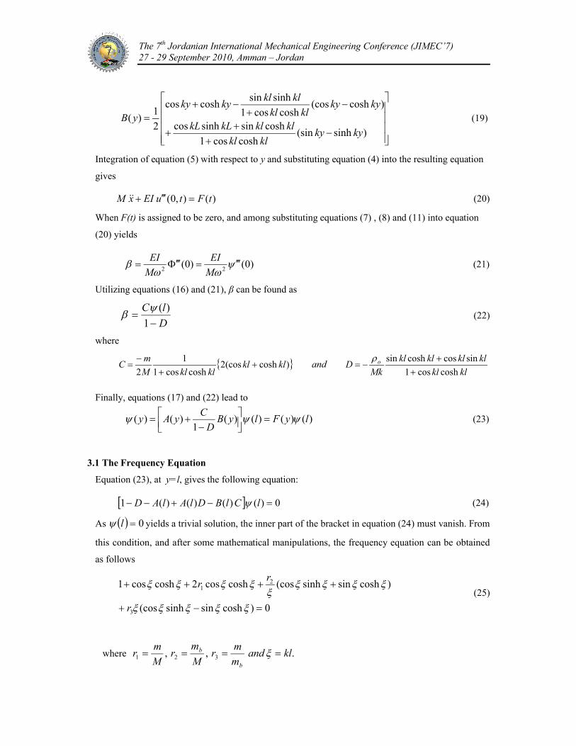
3.1 The Frequency Equation
Equation (23), at y=l, gives the following equation:
0)()()()(1 lClBDlAlAD (24)
As 0l yields a trivial solution, the inner part of the bracket in equation (24) must vanish. From
this condition, and after some mathematical manipulations, the frequency equation can be obtained
as follows
0)coshsinsinh(cos
)coshsinsinh(coscoshcos2coshcos1
3
21
r
rr
(25)
where .,, 321 klandm
mr
M
mr
M
mr
b
b
The 7th Jordanian International Mechanical Engineering Conference (JIMEC’7) 27 - 29 September 2010, Amman – Jordan
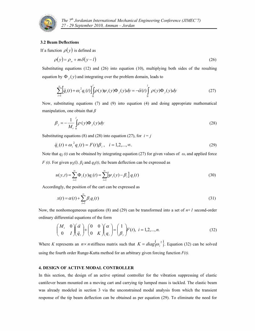
3.2 Beam Deflections
If a function y is defined as
lymy o (26)
Substituting equations (12) and (26) into equation (10), multiplying both sides of the resulting
equation by )( yj and integrating over the problem domain, leads to
dyyytdyyyytqtq j
l
j
l
ii
iii )()()()()()()()(001
2
(27)
Now, substituting equations (7) and (9) into equation (4) and doing appropriate mathematical
manipulation, one obtain that β
l
jt
j dyyyM 0
)()(1 (28)
Substituting equations (8) and (28) into equation (27), for i = j
.,...,2,1,)()()( 2 itFtqtq iiii (29)
Note that qi (t) can be obtained by integrating equation (27) for given values of ωi and applied force
F (t). For given ψi(l), βi and qi(t), the beam deflection can be expressed as
)()()()(),(11
tqytqytyu ii
iiii
i
(30)
Accordingly, the position of the cart can be expressed as
)()()(1
tqttx ii
i
(31)
Now, the nonhomogeneous equations (8) and (29) can be transformed into a set of n+1 second-order
ordinary differential equations of the form
.,...,2,1),(1
0
00
0
0nitF
qKqI
M
iii
t
(32)
Where K represents an nn stiffness matrix such that 2idiagK . Equation (32) can be solved
using the fourth order Runge-Kutta method for an arbitrary given forcing function F(t).
4. DESIGN OF ACTIVE MODAL CONTROLLER
In this section, the design of an active optimal controller for the vibration suppressing of elastic
cantilever beam mounted on a moving cart and carrying tip lumped mass is tackled. The elastic beam
was already modeled in section 3 via the unconstrained modal analysis from which the transient
response of the tip beam deflection can be obtained as per equation (29). To eliminate the need for
The 7th Jordanian International Mechanical Engineering Conference (JIMEC’7) 27 - 29 September 2010, Amman – Jordan
sensor placement on the tip of the cantilever beam since most of the practical control implementations
required that sensors and actuators be placed at certain accessible structural locations, Linear
Quadratic Estimator (LQE) technique is used for estimating the vibration of any point on the span of
the flexible cantilever beam mounted on a moving cart and carrying tip lumped mass and subjected to
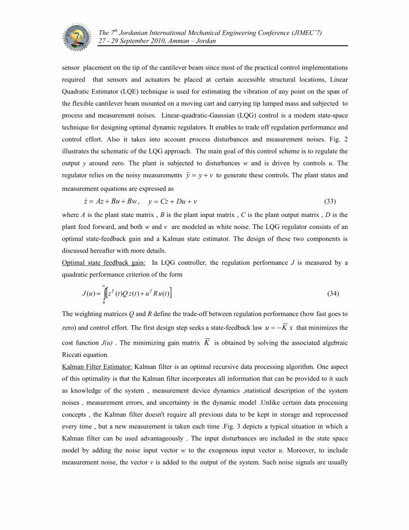
process and measurement noises. Linear-quadratic-Gaussian (LQG) control is a modern state-space
technique for designing optimal dynamic regulators. It enables to trade off regulation performance and
control effort. Also it takes into account process disturbances and measurement noises. Fig. 2
illustrates the schematic of the LQG approach. The main goal of this control scheme is to regulate the
output y around zero. The plant is subjected to disturbances w and is driven by controls u. The
regulator relies on the noisy measurements vyy to generate these controls. The plant states and
measurement equations are expressed as
BwBuAzz , vDuCzy (33)
where A is the plant state matrix , B is the plant input matrix , C is the plant output matrix , D is the
plant feed forward, and both w and v are modeled as white noise. The LQG regulator consists of an
optimal state-feedback gain and a Kalman state estimator. The design of these two components is
discussed hereafter with more details.
Optimal state feedback gain: In LQG controller, the regulation performance J is measured by a
quadratic performance criterion of the form
0
)()()()( tuRutzQtzuJ TT (34)
The weighting matrices Q and R define the trade-off between regulation performance (how fast goes to
zero) and control effort. The first design step seeks a state-feedback law xKu that minimizes the
cost function J(u) . The minimizing gain matrix K is obtained by solving the associated algebraic
Riccati equation.
Kalman Filter Estimator: Kalman filter is an optimal recursive data processing algorithm. One aspect
of this optimality is that the Kalman filter incorporates all information that can be provided to it such
as knowledge of the system , measurement device dynamics ,statistical description of the system
noises , measurement errors, and uncertainty in the dynamic model .Unlike certain data processing
concepts , the Kalman filter doesn't require all previous data to be kept in storage and reprocessed
every time , but a new measurement is taken each time .Fig. 3 depicts a typical situation in which a
Kalman filter can be used advantageously . The input disturbances are included in the state space
model by adding the noise input vector w to the exogenous input vector u. Moreover, to include
measurement noise, the vector v is added to the output of the system. Such noise signals are usually
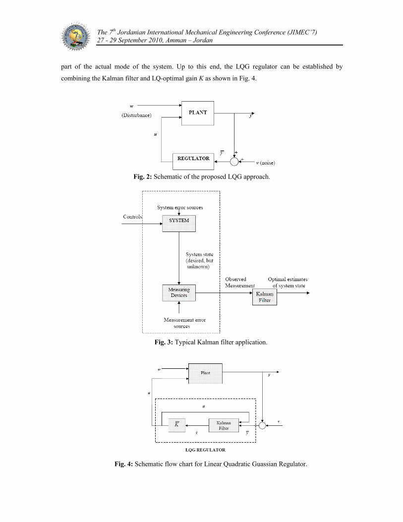
The 7th Jordanian International Mechanical Engineering Conference (JIMEC’7) 27 - 29 September 2010, Amman – Jordan
part of the actual mode of the system. Up to this end, the LQG regulator can be established by
combining the Kalman filter and LQ-optimal gain K as shown in Fig. 4.
Fig. 2: Schematic of the proposed LQG approach.
Fig. 3: Typical Kalman filter application.
Fig. 4: Schematic flow chart for Linear Quadratic Guassian Regulator.
The 7th Jordanian International Mechanical Engineering Conference (JIMEC’7) 27 - 29 September 2010, Amman – Jordan
5. NUMERICAL SIMULATION
The main objective of the current numerical study is to examine both open and closed loop responses
after implementing the developed LQG controller. The beam tip deflection was estimated using
Kalman filter estimator, in the presence of process and measurement noises using Kalman filter
estimator. Numerical values of the system parameters are selected as shown in table 1.
Table 1: System Parameters
ValueParameters
10.0 kgMass of cart, M1.0 mLength of elastic beam, L
0.788 kg/mMass per unit length of elastic beam, ρo
2.07 x 10⁻¹¹
N/m2Young's modulus of elastic beam, E
5.208 x 10⁻¹¹
m4Area moment of inertia of elastic beam, I
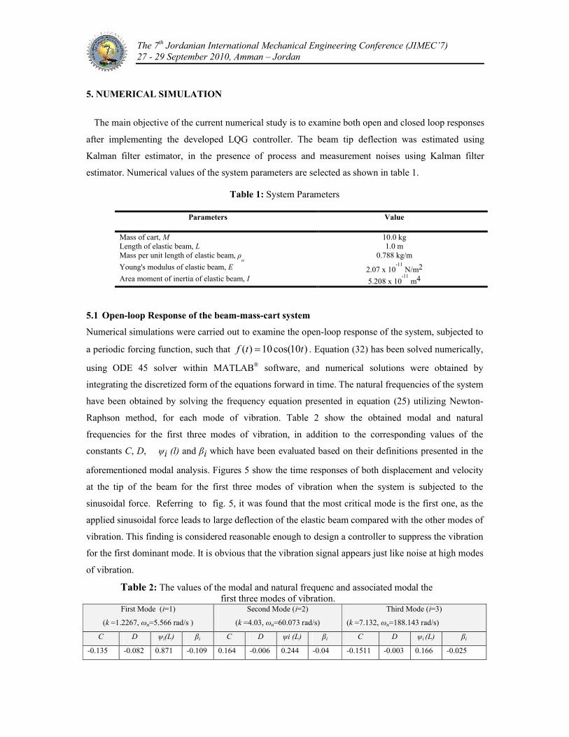
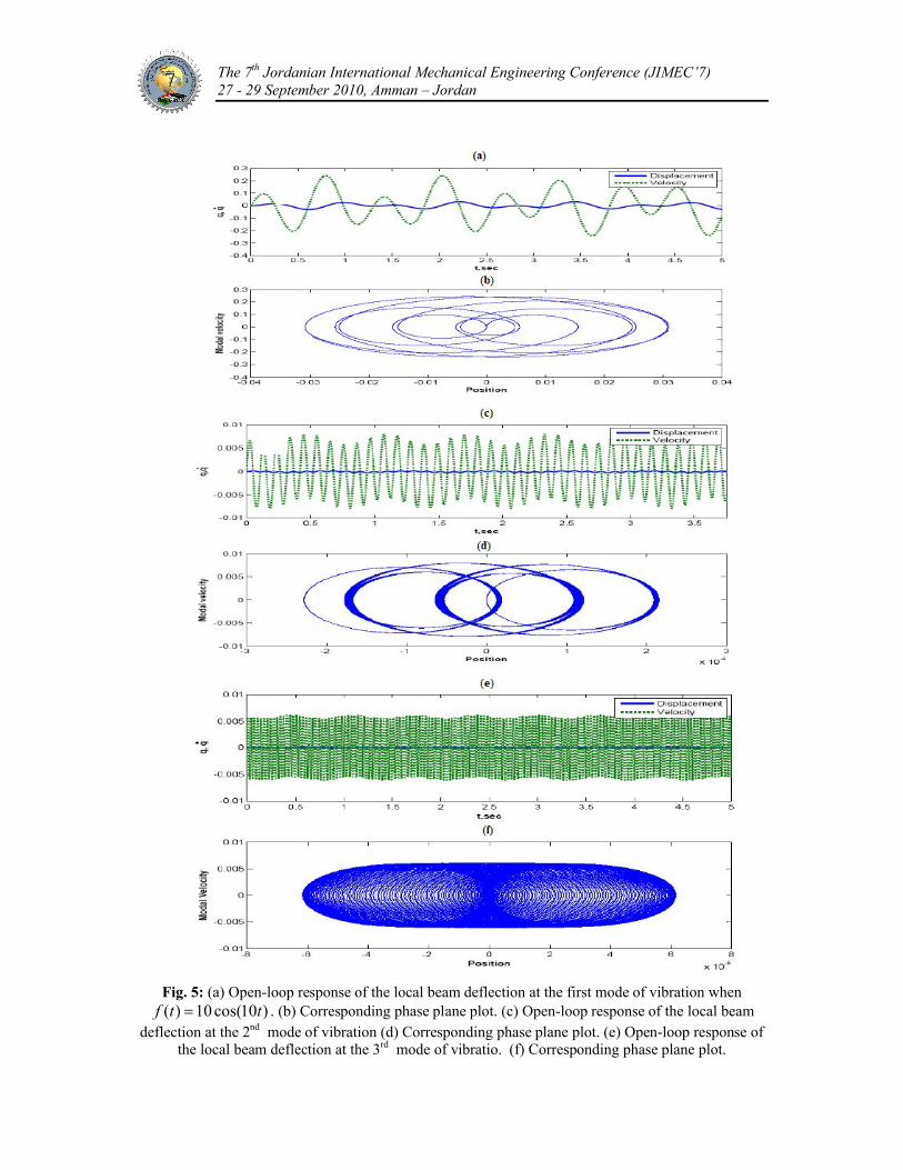
5.1 Open-loop Response of the beam-mass-cart system
Numerical simulations were carried out to examine the open-loop response of the system, subjected to
a periodic forcing function, such that )10cos(10)( ttf . Equation (32) has been solved numerically,
using ODE 45 solver within MATLAB® software, and numerical solutions were obtained by
integrating the discretized form of the equations forward in time. The natural frequencies of the system
have been obtained by solving the frequency equation presented in equation (25) utilizing Newton-
Raphson method, for each mode of vibration. Table 2 show the obtained modal and natural
frequencies for the first three modes of vibration, in addition to the corresponding values of the
constants C, D, ψi (l) and βi which have been evaluated based on their definitions presented in the
aforementioned modal analysis. Figures 5 show the time responses of both displacement and velocity
at the tip of the beam for the first three modes of vibration when the system is subjected to the
sinusoidal force. Referring to fig. 5, it was found that the most critical mode is the first one, as the
applied sinusoidal force leads to large deflection of the elastic beam compared with the other modes of
vibration. This finding is considered reasonable enough to design a controller to suppress the vibration
for the first dominant mode. It is obvious that the vibration signal appears just like noise at high modes
of vibration.
Table 2: The values of the modal and natural frequenc and associated modal thefirst three modes of vibration.
First Mode (i=1)
(k =1.2267, ωn=5.566 rad/s )
Second Mode (i=2)
(k =4.03, ωn=60.073 rad/s)
Third Mode (i=3)
(k =7.132, ωn=188.143 rad/s)
C D ψi(L) βi C D ψi (L) βi C D ψi (L) βi
-0.135 -0.082 0.871 -0.109 0.164 -0.006 0.244 -0.04 -0.1511 -0.003 0.166 -0.025
The 7th Jordanian International Mechanical Engineering Conference (JIMEC’7) 27 - 29 September 2010, Amman – Jordan
Fig. 5: (a) Open-loop response of the local beam deflection at the first mode of vibration when )10cos(10)( ttf . (b) Corresponding phase plane plot. (c) Open-loop response of the local beam
deflection at the 2nd mode of vibration (d) Corresponding phase plane plot. (e) Open-loop response of the local beam deflection at the 3rd mode of vibratio. (f) Corresponding phase plane plot.
The 7th Jordanian International Mechanical Engineering Conference (JIMEC’7) 27 - 29 September 2010, Amman – Jordan
The phase plane plot shows that there is one equilibrium point for the beam-mass-cart system where
there is no excitation force and the expected shape of phase plane plot in that case is a center profile.
On the other hand, the importance of the phase plane plot appears clearly in determining the
qualitative behavior of the dynamic systems such as stability.
5.2 Estimated beam tip deflection in the presence of process and measurement noises using
Kalman filter estimator.
In this part, Kalman filter is used to estimate the beam tip deflection in the presence of process
disturbance w and noise measurements v. In order to illustrate the efficiency of the filtration process,
the excitation force applied to the system is chosen to be similar to the selected force in the open loop
analysis. The process disturbance signal w is selected to be a random force of magnitude of 2 N.
Matlab Simulink model has been developed to represent the Kalman filter estimator in order to predict
the beam tip deflection in the presence of process and noise measurements. Kalman filter matrix was
obtained using a simple Matlab algorithm, while the beam-mass-cart system has been defined in its
state space representation. In order to demonstrate the capability of the proposed filtration scheme, the
estimated beam tip deflection is compared with the corresponding value obtained via the
unconstrained modal analysis. Fig. 6 shows the capability of the proposed estimator in producing
fairly accurate tip deflection. Kalman filter was found as powerful tool to eliminate hysteresis obtained
by process and measurement noises and to purify the output signal.
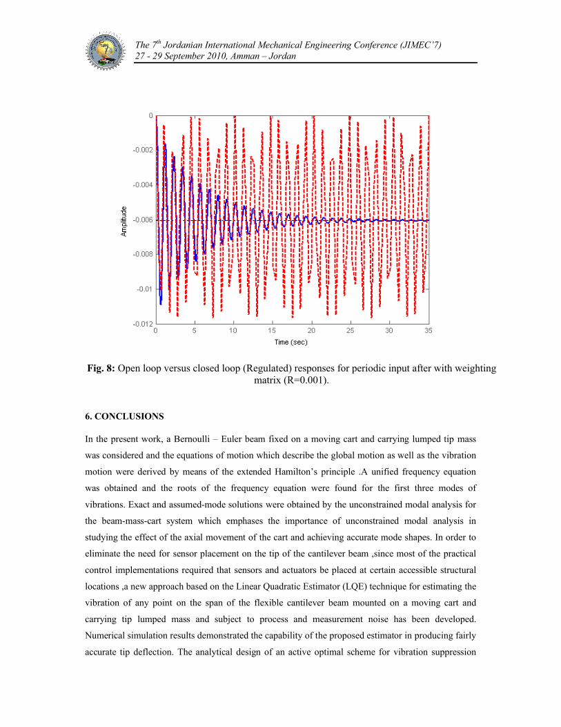
5.3 Closed-loop response using LQG optimal controller
In order to illustrate the regulator performance, both open and closed responses of the deflection at the
tip of the beam subjected to the periodic functions were compared as shown in figures 7 and 8 for
different weighting matrices. Referring to these figures, it was found that the linear quadratic regulator
is considered as efficient tool to eliminate the vibrations and stabilize the system for various inputs. It
is important to recognize that the dynamic matrix of the system shows that the system is conditionally
stable since the roots are pure imaginary while the new eigenvalues for the system after using
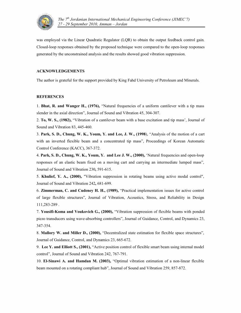
regulator are with negative real parts which assure stability for the system. By examining figures 7 and
8, we can conclude that the time required to achieve the steady state response can be controlled by by
increasing the weight of (Q) matrix and/or decreasing the weight matrix ( R) which has been used in
LQ regulator .Fig. 8 shows a fast closed loop response which was obtained by decreasing the value of
the weighting matrix (R). Generally if application requires fast decay of vibration, weighting matrix
(Q) must be increased while (Q) matrix shall be decreased, and the opposite can be performed if
reduction of the control effort is required.
The 7th Jordanian International Mechanical Engineering Conference (JIMEC’7) 27 - 29 September 2010, Amman – Jordan
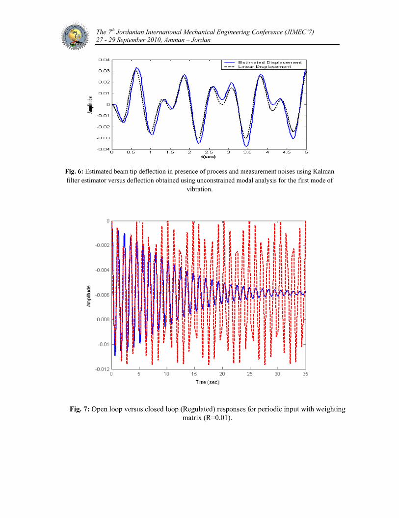
Fig. 6: Estimated beam tip deflection in presence of process and measurement noises using Kalman filter estimator versus deflection obtained using unconstrained modal analysis for the first mode of
vibration.
Fig. 7: Open loop versus closed loop (Regulated) responses for periodic input with weighting matrix (R=0.01).
The 7th Jordanian International Mechanical Engineering Conference (JIMEC’7) 27 - 29 September 2010, Amman – Jordan
Fig. 8: Open loop versus closed loop (Regulated) responses for periodic input after with weighting matrix (R=0.001).
6. CONCLUSIONS
In the present work, a Bernoulli – Euler beam fixed on a moving cart and carrying lumped tip mass
was considered and the equations of motion which describe the global motion as well as the vibration
motion were derived by means of the extended Hamilton’s principle .A unified frequency equation
was obtained and the roots of the frequency equation were found for the first three modes of
vibrations. Exact and assumed-mode solutions were obtained by the unconstrained modal analysis for
the beam-mass-cart system which emphases the importance of unconstrained modal analysis in
studying the effect of the axial movement of the cart and achieving accurate mode shapes. In order to
eliminate the need for sensor placement on the tip of the cantilever beam ,since most of the practical
control implementations required that sensors and actuators be placed at certain accessible structural
locations ,a new approach based on the Linear Quadratic Estimator (LQE) technique for estimating the
vibration of any point on the span of the flexible cantilever beam mounted on a moving cart and
carrying tip lumped mass and subject to process and measurement noise has been developed.
Numerical simulation results demonstrated the capability of the proposed estimator in producing fairly
accurate tip deflection. The analytical design of an active optimal scheme for vibration suppression
The 7th Jordanian International Mechanical Engineering Conference (JIMEC’7) 27 - 29 September 2010, Amman – Jordan
was employed via the Linear Quadratic Regulator (LQR) to obtain the output feedback control gain.
Closed-loop responses obtained by the proposed technique were compared to the open-loop responses
generated by the unconstrained analysis and the results showed good vibration suppression.
ACKNOWLEDGEMENTS
The author is grateful for the support provided by King Fahd University of Petroleum and Minerals.
REFERENCES
1. Bhat, R. and Wanger H., (1976), “Natural frequencies of a uniform cantilever with a tip mass
slender in the axial direction”, Journal of Sound and Vibration 45, 304-307.
2. To, W. S., (1982), “Vibration of a cantilever beam with a base excitation and tip mass’, Journal of
Sound and Vibration 83, 445-460.
3. Park, S. D., Chung, W. K., Youm, Y. and Lee, J. W., (1998), “Analysis of the motion of a cart
with an inverted flexible beam and a concentrated tip mass”, Proceedings of Korean Automatic
Control Conference (KACC), 367-372.
4. Park, S. D., Chung, W. K., Youm, Y. and Lee J. W., (2000), ‘Natural frequencies and open-loop
responses of an elastic beam fixed on a moving cart and carrying an intermediate lumped mass”,
Journal of Sound and Vibration 230, 591-615.
5. Khulief, Y. A., (2000), "Vibration suppression in rotating beams using active modal control",
Journal of Sound and Vibration 242, 681-699.
6. Zimmerman, C. and Cudeney H. H., (1989), “Practical implementation issues for active control
of large flexible structures”, Journal of Vibration, Acoustics, Stress, and Reliability in Design
111,283-289 .
7. Yousifi-Koma and Voukovich G., (2000), “Vibration suppression of flexible beams with ponded
piezo transducers using wave-absorbing controllers”, Journal of Guidance, Control, and Dynamics 23,
347-354.
8. Mallory W. and Miller D., (2000), “Decentralized state estimation for flexible space structures”,
Journal of Guidance, Control, and Dynamics 23, 665-672.
9. Lee Y. and Elliott S., (2001), “Active position control of flexible smart beam using internal model
control”, Journal of Sound and Vibration 242, 767-791.
10. El-Sinawi A. and Hamdan M. (2003), “Optimal vibration estimation of a non-linear flexible
beam mounted on a rotating compliant hub”, Journal of Sound and Vibration 259, 857-872.