Embed Size (px)
Citation preview
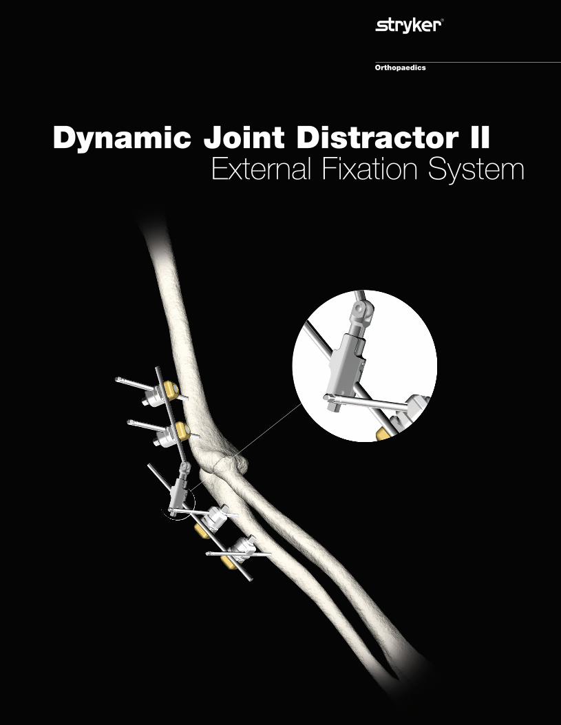
Dynamic Joint Distractor IIExternal Fixation System
051470 8/15/05 9:22 AM Page 1

2
3
2
1
6
Dynamic Joint Distractor II
4 5
B. F. Morrey, M.D.Illustrations by Matthew Morrey, M.S.
1. DJD II Body2. Humeral Guide3. Pin Insertion Guides4. Hoffmann® II Compact™ Instruments5. Hoffmann® II Compact™ Components and Apex® Pins
051470 8/15/05 9:22 AM Page 2

3
Overview
There are two principal goals simultaneouslyachieved with the Dynamic Joint DistractorII (DJD II):1) to allow active or passive motion 2) to protect the articular surfaces and thecollateral ligaments
Design ConceptReliable identification of the axis of rotation and rigid skeletal fixation can be obtained by an articular device which replicates the axisof rotation.
Skeletal fixation on the ulna with the DJD IIallows protection or neutralization of thearticular surface for a variety of clinical cir-cumstances.Motion in flexion/extension is allowed with-out encumbrance particularly in both thearticular surface and the collateral ligaments.
OPTIONS: The DJD II may be used in eithera unilateral or bilateral configuration. Thisallows a great deal of flexibility of use and awider range of indications (Fig. 1).
Features & Benefits• Simplified frame construction
• Integrated hinge designed to replicate the elbow’s natural axis of rotation
• Integrated joint distraction mechanism (1-10mm)
• Unilateral or bilateral frame configurations
• Independent pin placement reduces the potential of neurovascular injury
• Compatible with Hoffmann® II Compact™ couplings
• Simple, user friendly instrumentation
Figure 1
051470 8/15/05 9:22 AM Page 3

4
The Dynamic Joint Distractor II System
• The DJD II body distraction mechanismincludes a graduated scale to allow con-trolled distraction. Its 5mm square headscrew is identical to the 5mm square headscrews of the Hoffmann® II Compact™couplings allowing the use of the samewrench.
HumeralRod
DistractionScrew
UlnarRod
Hinge
Graduated mil-limeter scaleallows precisedistraction
Dynamic Joint Distractor II BodyThe DJD II body has been specificallydesigned to provide strength, reduce bulkiness and weight and simplify use.
• The DJD II body is composed of two 5mmdiameter stainless steel rods linked togetherby a hinge which includes an integrated dis-traction mechanism to distract the elbowjoint.
• The DJD II body’s ulnar and humeral rodsare compatible with the Hoffmann® IICompact™ couplings, allowing snap-clickease of use. The complex anatomy of theelbow makes independent pin placement acrucial advantage in reducing the potentialof neurovascular injury.
• The DJD II body’s cannulated hinge allowsthe positioning of the DJD II body over the3mm Apex® reference pin which has beeninserted into the axis of rotation of theelbow (see operative technique pg. 7).Therefore, the DJD II body hinge isdesigned to replicate the anatomical axis ofrotation and allows natural mobilization ofthe elbow. The removal of the reference pinat the end of the surgery to reduce the riskof elbow joint infection.
• The DJD II body’s distraction mechanismallows distraction up to 10 mm (typically 2-3mm distraction is sufficient to accomplishthe goals of the procedure) without anyadditional components.
051470 8/15/05 9:22 AM Page 4

5
Pin-to-Rod CouplingIndependent pin placement is a key factor to successful elbow surgery where complexanatomy dictates the pin insertion areas. Thepin-to-rod coupling of the Hoffmann® IICompact™ System has been specificallydesigned to provide the freedom of singlepin placement with ease of use.
• Designed to accept 3 & 4mm Apex® pinsand 5mm rods
• Integrated spring loaded snap-fit mechanism allows easy assembly and temporary fixation during adjustment procedures
• Assemble laterally with a “click effect” ofthe pin and/or rod
• Radially serrated tooth design providesexcellent locking and rotational stability
• Top locking provides easy access via a 5mmsquare head
Rod-to-Rod CouplingThe rod-to-rod coupling of the theHoffmann® II Compact™ system connectstwo 5mm rods to each other. Its anti-rota-tional snap-fit mechanism ensures a firmgrip allowing a good locking of the DJD IIbody if necessary. Locking may be used tominimize unwanted elbow joint movementduring the first 24 hours after the surgery(see operative technique).• Designed to accept 5mm rods• Integrated spring loaded snap-fit mecha-
nism allows easy assembly and temporaryfixation during adjustment procedures
• Assembles laterally with a “click effect” ofthe rods
• Radially serrated tooth design providesexcellent locking and rotational stability
• Top locking provides easy access via a 5mmsquare head
051470 8/15/05 9:22 AM Page 5

Clinical cases
6
Case 1: Heterotopic bone formation after neurotrauma causing complete ankylosis of the joint.
Case 2: Post-traumatic stiffness after supracondylar fracture.
Pre-operative X-ray Post-operative Post-operative Frame removal at 6 weeksROM: 60° X-ray frame ROM: 120°
Pre-operative X-ray Post-operative X-ray Post-operative Range of Motionframe (ROM): 135°
Case 3: Fascia lata arthroplasty. Rheumatoid arthritis: right elbow joint ankylosis since 14 years.
Pre-operative X-ray Post-operative Post-operativeX-ray frame
051470 8/15/05 9:22 AM Page 6

7
Operative Technique
Dynamic Joint Distractor – Unilateral Frame
Patient Positioning & AnatomicalRepairThe patient is supine with a sandbag underthe scapula, the arm is draped free with anon-sterile tourniquet and brought acrossthe chest (Fig. 2). The elbow is exposedaccording to the pathology present.Regardless of the exposure or pathology,identifying the essential landmarks forhumeral pin placement in the axis is critical.
On the lateral aspect of the capitellum, atubercle is present at the site of the origin ofthe lateral collateral ligament. This tuberclealso represents the geometric center of curva-ture of the capitellum, which is the site ofthe flexion axis of the elbow, and is the pointthrough which a 3mm Apex® humeral refer-ence pin will pass (Fig. 3). If this anatomicfeature has been altered by pathology, thenthe center of the curvature of the trochlea is identified as the axis of rotation since theulna rotates on the humerus and rotation on the capitellum is a secondary feature.
On the medial aspect of the distal humerus,the axis of rotation lies just anterior and infe-rior to the medial epicondyle. The referencepin is placed in this region, or slightly anteri-or and proximal to this location (Fig. 3). Thisrepresents a safe zone relative to the ulnarnerve. If a medial frame is to be applied, theulnar nerve is identified and protected at thetime of insertion of the 3mm Apex® humeralreference pin.
For all frame applications the 3mm Apex®humeral reference pin is drilled or tapped10-20mm into the distal humerus along theaxis of rotation.
Articular FractureThe articular fracture is approached accord-ing to surgeon preference, the specificpathology, and the treatment goals.
Olecranon fractures are easily exposed andthe fixator readily applied. Fractures involv-ing the coronoid require more extensiveexposures as described on the following page for the release of the stiff elbow.
Distal humeral fractures may be treated byexposure with olecranon osteotomy or a triceps reflection technique. If the fracturefixation device(s) or collateral ligament reattachment precludes the introduction ofa 3mm reference pin, a small Kirschner wireis inserted in a manner to replicate the axis of rotation.
Figure 3
The landmarks on the distal humerus medial and lateral.
“Universal” posterior skin incision
Ulnar n.
Medial epicondyle
Center ofcapitellum/
trochlea
Figure 2
The patient is supine, the arm is brought across the chest.
NOTE:Close proximity to nerve
051470 8/15/05 9:22 AM Page 7

8
The Stiff ElbowIf treating the elbow for stiffness, the previ-ous incision is entered, and an extensile postero-lateral joint release is used.
Typically, the triceps is reflected from the tip of the olecranon. However, in someinstances, such as when elbow flexion is nor-mal, the triceps may be left intact. A com-plete anterior capsular excision is required.The capsule is exposed by releasing the com-mon extensor tendon. If the pathology isextrinsic to the joint, the anterior capsule isexcised but the lateral collateral ligament ispreserved. If the joint is abnormal and is tobe altered, such as with an interpositionarthroplasty, the lateral collateral ligament iselevated as a flap of tissue from its origin atthe lateral condyle. This is tagged and reflect-ed distally, providing an extensive exposure(Fig. 4), but must be repaired and reattachedat closure.
When the pathology involves a joint surfacethat requires an extensive dissection, theidentification and protection of the ulnarnerve is necessary.
Ideally, a single posterior incision is utilized,and a subcutaneous dissection is carried out to the medial aspect of the triceps. Ifa previous Kocher skin incision has beenplaced laterally, ulnar nerve exposure isaccomplished through a supplemental medial incision.
In any event, the ulnar nerve is identified,but is usually not translocated anteriorly. It is important to protect the nerve, first duringthe capsular dissection and later at the timeof the 3mm Apex® humeral reference pinplacement. If ulnar nerve symptoms are pres-ent, then the nerve is decompressed withdefinitive management, according to the dictates of the pathology.
At closure with the 3mm Apex® humeral reference pin in place, 2mm holes are madedistal and proximal to the pin for reattach-ment of the lateral collateral ligament (Fig. 5).
Bunnell sutures or suture anchors are placedthrough the radial (lateral) collateral liga-ment and through the holes drilled throughthe lateral column around the flexion pin.
Figure 5Holes are placed around the axis of rotation, allowing the ligamentto be reattached.
Extensor “sleeve”
Anconeus
Lateralcapsule 3mm Apex® refer-
ence pin
Lateralcollateralligament
Ligament reat-tachment holes
Figure 4An extensile surgical exposure typically involves releasing ofthe lateral collateral ligament.
051470 8/15/05 9:22 AM Page 8

9
1. Axis of rotationDetermine the external landmarks of theaxis of rotation and place the humeral(axis) reference pin guide in line with theaxis of rotation. (Typically, the pointed tipof the humeral axis guide is placed on themedial side with the cannulated pin guideon the lateral side.) (Fig. 6).
2. Reference pin placementThe reference pin acts as a guide duringframe construction.
Insert laterally the 3mm diameter selfdrilling/self tapping Apex® pin throughthe humeral (axis) reference pin guide inthe axis of rotation. For unilateral frameconstruction insert the pin to a depth of
15-20mm. For bilateral frames it is recommended to replace the 3mm Apex®humeral reference pin by a 3mm smoothtransfixing Apex® pin which is insertedacross the distal humerus (see BilateralFrame Option).
N.B.: The 3mm pin is a reference pin and is the essential reference required toaccurately assemble the DJD II frame andto properly insert the humeral and ulnarpins. It will be removed after frame con-struction.
OPTIONS: If ligament repair/reconstruc-tion precludes use of a drill bit, a “stylus”guide may be inserted.
3. Remove the humeral (axis) ref-erence pin guide
4. Placement of the DJD II frameon the reference pin The hollow bored hinge of the DJD II isplaced over the reference pin so that itshinge is exactly in the same axis of rota-tion as the natural axis of rotation of theelbow. Verify that the distraction device isfully compressed before frame construc-tion.
Figure 6
The pointed tip of the humeral axis guide is placed medially under direct vision, allowing accurate orientation of the axis reference pin.
NOTE: Close proximity to nerve
051470 8/15/05 9:22 AM Page 9

10
5. Pin insertionAt this stage, depending on surgeon preference or features of the case, onemay insert either the humeral or theulnar pins.
6. Humeral pin insertions6.1 Insert the proximal pin first. According to
the pin diameter (3mm or 4mm), placethe appropriate pin insertion guide overthe humeral rod so that the pin guideholes allow engagement of the lateralhumerus (Fig. 7)*.
N.B.: The 5mm humeral rod is aligned to the anterior cortex of the humerus(Insert).
*Care should be taken to identify and protectthe radial nerve
6.2 The proximal humeral self drilling/selftapping Apex® 4mm (or 3mm) pin isinserted into the lateral cortex of thehumerus through the pin guide andengaged in the opposite cortex.
N.B.: The second hole of the pin inser-tion guide indicates the minimum distance between 2 pins. However, it isrecommended to increase the distancebetween the pins by placing the pin guidefurther from the first pin as described insteps 6.5 and 7.5.
6.3 The pin guide is then removed.6.4 The proximal pin is fixed to the humeral
rod with a Hoffmann® II Compact™ pin-to-rod coupling. This is then tight-ened using a Hoffmann II Compactwrench (Fig. 8).
N.B.: Hoffmann II Compact pin-to-rodcouplings accept pins of both 3mm and4mm diameter.
Alignment along the anteriorhumeral cortex
Figure 8The proximal pin is fixed to the humeral rod with theHoffmann®II Compact™ pin-to-rod coupling.
Figure 7The fixator is placed over the reference pin and using the pininsertion guide a proximal half pin is placed through the lateraland medial humeral cortices.
Care should be taken to identify and protect the radial nerve.
051470 8/15/05 9:22 AM Page 10

11
6.6 The second 4mm (or 3mm) self drilling/self tapping Apex® pin is now insertedmore distally through the pin guide (Fig. 9).
N.B.: The pins need not necessarily beparallel.
If a different pin insertion angulation isrequired to access a more adequate areaon the humerus, slightly rotate and/orincline the pin guide over the humeralrod until the desired pin insertion areacan be reached. By providing proper pin-rod distance, the system allows anindependent pin placement (Insert).
6.5 Place the pin guide over the humeral rod more distally (closer to the hinge).
Figure 9Using the pin insertion guide a second half pin is placed across the proximal humerus distal to the first.
Rotation over the rod allows precise pin placement
Inclination over the rod allows precise pin placement
051470 8/15/05 9:22 AM Page 11

12
6.7 The pin guide is then removed.
6.8 The distal pin is fixed to the humeral rod with a Hoffmann® II Compact™ pin-to-rod coupling which is then tight-ened using a Hoffmann II Compactwrench.
7. Ulnar pin insertions7.1 According to the pin diameter (3mm or
4mm), place the appropriate pin guideover the ulnar rod to access the lateralaspect of the ulna.
N.B.: 3mm pins are usually preferred asthe ulna diameter is smaller.
7.2 The distal ulnar 3mm (or 4mm) selfdrilling/self tapping Apex® pin is insertedinto the lateral cortex through the pinguide and pierces the medial ulnar cortex(Fig. 10).
7.3 The pin guide is then removed.
7.4 The distal pin is fixed to the ulnar rod with a Hoffmann® II Compact™ pin-to-rod coupling which is then tight-ened using a Hoffmann II Compactwrench.
Figure 11
A second pin is placed proximally using the pin insertion guide.
The distal ulna pin is applied with the use of the pin insertionguide.
Figure 10
051470 8/15/05 9:22 AM Page 12

13
7.5 Place the pin guide over the ulnar rodmore proximally i.e. between the distrac-tion mechanism and the distal pin (Fig. 11).
7.6 The proximal self drilling/self tappingApex pin can now be inserted throughthe pin guide.
N.B.: As with the humerus, the pins donot necessarily need to be parallel. If adifferent pin insertion angle is requiredto access a more adequate pin insertionarea, slightly rotate the pin guide over the ulnar rod until such a pin insertionarea can be reached. By providing properpin-rod distance, the system allows anindependent pin placement (see Fig. 9).
7.7 The pin guide is then removed.
Figure 13
Using a Hoffmann® II Compact™ wrench the elbow joint isdistracted generally 2-3mm.
Apex® axis reference pin removal.
Figure 12
051470 8/15/05 9:22 AM Page 13

Dynamic Joint Distractor II – Bilateral Frame Option
14
7.8 The proximal pin is fixed to the ulnar rodwith a Hoffmann® II Compact™ pin-to-rod coupling which is then tightenedusing a Hoffmann® II Compact™ wrench.
7.9 If the indication requires the use of theproximal ulnar pin in the olecranon, itcan be inserted through the pin guide.Once again, this pin will be once again
attached to the ulnar rod with aHoffmann® II Compact™ pin-to-rod coupling which is then tightened.
Lateral DJD II application
2
3
1
Axis of rotation is replicated through a 3mmsmooth transfixing pin (half pins for separate lat-eral or medial applications are acceptable)
051470 8/15/05 9:22 AM Page 14
15
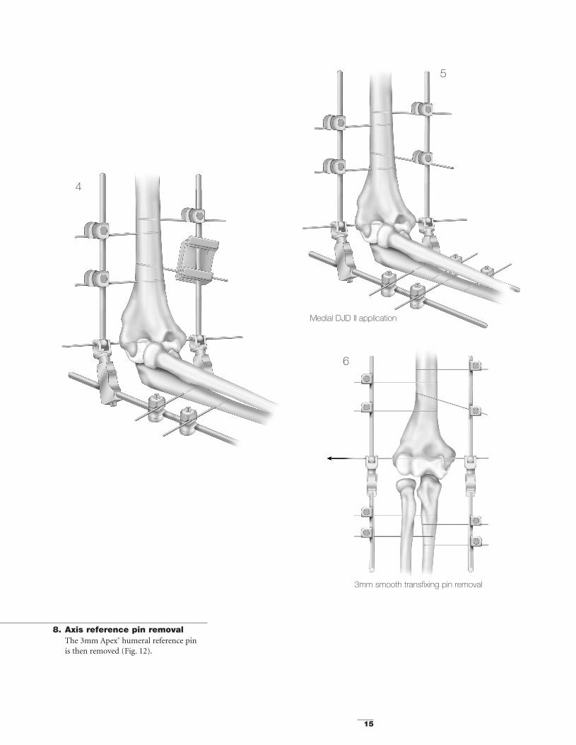
8. Axis reference pin removalThe 3mm Apex® humeral reference pin is then removed (Fig. 12).
3mm smooth transfixing pin removal
Medial DJD II application
4
5
6
051470 8/15/05 9:22 AM Page 15

16
9. DistractionThe ulna is separated from the humerusby turning the distraction screw using aHoffmann® II Compact™ wrench.
Typically 2-3mm of distraction is suffi-cient to accomplish the goals of the pro-cedure (Fig. 13). Skin closure is usuallydeferred until the distraction is applied.
If greater stability of the external fixatoris desired, a second half frame is appliedover a 3mm smooth transfixing pin orover a medial reference half pin on themedial aspect. Independent medial halfpins are then applied on both thehumerus and the ulna as described in steps 6 and 7 (see Fig. 1).
Dynamic Joint Distractor II – Medial Frame Option
Figure 14After identification of the medial intermuscular septum the brachialis and soft tissues are swept from the anterior aspect of the distal humerus.
Figure 15
3mm Apex® reference pin inserted medially
Figure 16
Percutaneous pin placement
Brachialis m.
Ulnar n.Intermuscula
septum
Percutaneouspin placement
Pronator teres m.
051470 8/15/05 9:22 AM Page 16

17
As with the unilateral frame configuration,the 3mm smooth transfixing pin which replicates the axis of rotation of the elbow isremoved at the end of the surgery to reducethe risk of joint infection.
Percutaneous Application
Figure 17Percutaneous application directs the 3mm Apex®
humeral reference pin from the lateral epicondyle towards the medial epicondyle.
Figure 18Once the frame is applied the distraction device may sometimesbe used to help reduce the glenohumeral joint.
051470 8/15/05 9:22 AM Page 17

Dynamic Joint Distractor II Frame Reference Guide
18
1. Unilateral frame (Lateral) 2. Bilateral frame
3. Unilateral frame (Medial)
1. 2. 3.
DJD II body (Cat No 5195-0-010) 1 ea. 2 ea. 1 ea.
Pin-to-rod coupling (Cat No 4940-1-020) 4 ea. 8 ea. 4 ea.
Apex® pins 4 ea. 8 ea. 4 ea.
Component Configuration
Example
Quanti
ty
051470 8/15/05 9:22 AM Page 18

19
Postoperative Management Recommendations
The medial aspect of the triceps is identifiedalong with the ulnar nerve. The nerve is notnecessarily transposed unless appropriate forthe case. The intermuscular septum is identi-fied proximal to the epicondyle and followedanteriorly to the humerus. The soft tissuesare elevated from the distal humerus and the pronator attachment is released from the anterior superior aspect of the medialepicondyle. Elevating the soft tissue sleeveallows exposure of the anterior medial capsule (Fig. 14).
To apply the fixator, place the humeral (axis)reference pin guide in line with the axis ofrotation.
The guide stylus is placed medially and thepointed tip is placed laterally at the axis sitelocated at the lateral tubercle. Insert mediallythe 3mm Apex® humeral reference pin (Fig.15). The application proceeds as with the lateral frame option (see page 7).
However, care must be exercised to observeand protect the ulnar nerve and anteriorneuromuscular bundle at the time of humer-al pin insertion. This is best done by directlyobserving the entrance site of the pins at thehumerus. (Fig. 16).
Post-op Management Time Period
Analgesia Recovery room to 48 hours
Continuous Passive Motion (CPM) Day 1-21 for stiffnessDay 1-42 for fracture
DJD II removal 3 weeks for stiffness6 weeks for fracture
Flexion and extension splints program 12 weeks:21 hr/day during 3 weeks18 hr/day during 3 weeks15 hr/day during 6 weeks
Long-term splints Maintenance at night during 3 months(longer as needed)
051470 8/15/05 9:22 AM Page 19

Components
20
Catalogue DescriptionNumber
DJD II component
5195-0-010 DJD II body
Hoffmann® II couplings
4940-1-010 Hoffmann® II Compact™ rod-to-rod coupling
4940-1-020 Hoffmann® II Compact™ pin-to-rod coupling
Recommended Hoffmann® II Compact™ rod
5049-5-250 Stainless Steel connecting rod 5mm x 250mm
5049-5-525 Carbon connecting rod 5mm x 250mm
Recommended Apex® 3 & 4mm pins
Self drilling/self tapping5038-5-080 Pin diameter 3mm, length 80mm, thread length 20mm
5038-2-110 Pin diameter 3mm, length 110mm, thread length 25mm
5023-2-090 Pin diameter 4mm, length 90mm, thread length 20mm
5023-3-120 Pin diameter 4mm, length 120mm, thread length 30mm
5023-5-150 Pin diameter 4mm, length 150mm, thread length 40mm
Blunt5036-2-080 Pin diameter 3mm, length 80mm, thread length 20mm
5036-2-110 Pin diameter 3mm, length 110mm, thread length 25mm
5027-2-090 Pin diameter 4mm, length 90mm, thread length 20mm
5027-3-120 Pin diameter 4mm, length 120mm, thread length 30mm
5027-4-150 Pin diameter 4mm, length 150mm, thread length 40mm
Smooth transfixing pin (bilateral frame construction)5045-5-200 Smooth transfixing diameter 3mm, length 200mm
051470 8/15/05 9:22 AM Page 20

21
Instruments
Catalogue DescriptionNumber
DJD II specific instruments
5195-1-010 Humeral guide
5195-1-020 3mm pin insertion guide
5195-1-030 4mm pin insertion guide
Hoffmann® II Compact™ standard instruments
4940-9-030 5mm wrench/3 & 4mm pin driver
5150-9-005 5mm spanner wrench
4940-9-010 Stabilization/reduction wrench
4920-9-020 Thumbwheel
Tray
5195-9-100 Storage and sterilization case
051470 8/15/05 9:22 AM Page 21

22
Notes
051470 8/15/05 9:22 AM Page 22

051470 8/15/05 9:22 AM Page 23

The information presented in this brochure is intended to demonstrate the breadth of Stryker product offerings. Alwaysrefer to the package insert, product label and/or user instructions before using any Stryker product. Surgeons must alwaysrely on their own clinical judgment when deciding which treatments and procedures to use with patients. Products may notbe available in all markets. Product availability is subject to the regulatory or medical practices that govern individual mar-kets. Please contact your Stryker representative if you have questions about the availability of Stryker products in your area.
The marks bearing the symbol TM are trademarks of Stryker.The marks bearing the symbol ® are registered trademarks of Stryker.
Literature Number: LDJDS/ST Rev. 2GC/GS 500 06/05
Copyright © 2005 StrykerPrinted in USA
Dynamic Joint Distractor IIExternal Fixation System
Monotube® TRIAXTM
External Fixation SystemUnilateral frame system designed to handle a wide variety of fractures and limb-lengtheningapplications. This simple, color-coded system offers both dynamic and carbon tubes for individualized performance and economy. True simplicity, versatility, and economy.
Hoffmann®II**External Fixation SystemModular frames which allow for true independent pin placement. Completely compatiblewith Original Hoffmann® components, this new system improves flexibility and ease-of-use,while enhancing frame economics through minimal componentry. It’s external fixation with a “snap.”
Hoffmann®II CompactTM
External Fixation SystemDesigned to complement the anatomy of the distal radius by allowing independent movementof its clamps in multiple planes. Standard unilateral or bi-lateral bridging frames for intra-articular fractures and peri-articular non-bridging frames for extra-articular fractures.Fully compatible with the Hoffmann® II system, based on a spring-loaded snap-fit mechanismthat improves flexibility and ease-of-use.
Dynamic Joint Distractor IIThe DJD II is a Dynamic Elbow Joint Distractor. Fully compatible with the Hoffmann® IICompact™ System, it is designed to treat post-traumatic elbow stiffness as well as acute elbowtrauma fractures.
Apex® ****Pin FixationEvery Fixator incorporates the high quality pin-to-bone interface provided by Apex® Pins.The Apex® Pin cuts more sharply with less torque, friction and heat upon insertion improvingpurchase while minimizing the risk of pin tract problems. Available in self-drilling and blunttip designs, only from Stryker!
REFERENCES1. Kenwright J, Richardson JB, Cunningham JL, White SH, Goodship AE, Adams MA, Magnussen PA, Newman JH.
Axial movement and tibial fractures. J Bone Joint Surgery 1991:73b.2. Hart MB, Wu JJ, Chao EYS, Kelly PJ. External skeletal fixation of canine tibial osteotomies. Compression compared
with no compression. J Bone Joint Surgery 1985; 67 A:598.
Hoffmann® II Swiss Patent Application: 01-709/94-3. Other Patents Pending. * Patents: EU 385,929; 374,093; Canada1,193,506; U.S. 5,160,335 and 5,207,676. ** Swiss Patent Application: 02-709/94-3. Other Patents Pending. *** Patents:EU 190,990; U.S. 4,784,125; 5,095,919. **** Patents: EU 230,856; Swiss CH 671,150; U.S. 4,978,350. †Data on file atStryker USA.
325 Corporate DriveMahwah, NJ 07430t: 201 831 5000
www.stryker.com
051470 8/15/05 9:22 AM Page 24