Embed Size (px)
Citation preview
• Dynamic (G2) Model Design
oocumenttit1e: Document
Document number: 24590-WTP-MDD-PR-01-002, Rev 14
Contract number: DE-AC27-01RV14136
Department: Plant Engineering
Author(s): Yueying Deng ~ ~ Checked by: Venkatesha Arakali ~ ~
Issue status: Approved
Approved by: Peter Benson
Approver's position: Flowsheet Integration Manager
Approver's signat~re: - 'i:t\::,.o. A ~ Signature
Approved by:
Approver's position:
Approver's signature:
River Protection Project Waste Treatment Plant 2435 Stevens Center Place Richland, WA 99354 United States of America Tel: 509 371 2000
Marshall Miller
Plan~ineering M,~ Chief~eer
//~~ //~~ 5--3-1e 7 1Signature ~~~Da-t-e~~-
24590-PADC-F00041 Rev 8 (Revised 3/5/2018)
Issued byRPP-WTP PDC
24590-WTP-MDD-PR-01-002, Rev 14 Dynamic (G2) Model Design Document
Page ii
24590-PADC-F00041 Rev 8 (Revised 3/5/2018)
History Sheet
Rev Reason for revision Revised by
14 Updated to reflect the as-built design of the Dynamic (G2)
Flowsheet Version 9.0. Major changes that affect the WTP
equipment configuration, chemical processes, operating
parameters and logic included:
LAW Melter Downtime Effects (24590-WTP-MCR-PENG-17-
0001)
DFLAW Addition to G2 Flowsheet (24590-WTP-MCR-
PENG-17-0014)
Startup Commissioning of the DFLAW for G2 (24590-WTP-
MCR-PENG-17-0015)
Oracle and Matlab Scripts for G2 Version 9.0 (24590-WTP-
MCR-PENG-17-0016)
A complete revision history is provided in Appendix O.
Y Deng
24590-WTP-MDD-PR-01-002, Rev 14 Dynamic (G2) Model Design Document
Page iii
24590-PADC-F00041 Rev 8 (Revised 3/5/2018)
Contents
History Sheet ................................................................................................................................. ii
Executive Summary ................................................................................................................... viii
Acronyms ........................................................................................................................................x
1 Introduction ...........................................................................................................................1
2 Scope .......................................................................................................................................2
2.1 Model Basis ............................................................................................................................................. 2
2.2 G2 Bundle ............................................................................................................................................... 2
2.3 Life Cycle Documents ............................................................................................................................ 4
2.4 Configuration Management .................................................................................................................. 4
3 Model System Description ....................................................................................................5
3.1 Time Steps and Dynamic Material Balance ......................................................................................... 5
3.2 Feed Vector ............................................................................................................................................. 5
3.3 Equipment Initialization ........................................................................................................................ 6
3.4 Component Lists..................................................................................................................................... 7
3.5 Equipment Classes ................................................................................................................................. 7
3.6 Volume Calculations ............................................................................................................................ 13
3.7 Common Operating Rules ................................................................................................................... 13
3.8 System Specific Operating Logic ........................................................................................................ 43
3.9 Workspace Description ...................................................................................................................... 159
4 Model Construction ...........................................................................................................161
4.1 G2 Core ............................................................................................................................................... 161
4.2 Computation Environment ................................................................................................................ 170
4.3 Inputs and Outputs ............................................................................................................................ 170
4.4 G2 Mass Balance Calculator ............................................................................................................. 174
4.5 Oracle Scripts for G2 ......................................................................................................................... 182
4.6 Matlab Scripts for G2 ........................................................................................................................ 203
4.7 Feed Vector Database ........................................................................................................................ 217
4.8 Lineflush Table Database .................................................................................................................. 219
5 Reference ............................................................................................................................220
Appendices
Appendix A Component List .................................................................................................... A-i
Appendix B Chemical Adds ...................................................................................................... B-i
24590-WTP-MDD-PR-01-002, Rev 14 Dynamic (G2) Model Design Document
Page iv
24590-PADC-F00041 Rev 8 (Revised 3/5/2018)
Appendix C Sample Identification and Logic ......................................................................... C-i
Appendix D Component Splits ................................................................................................. D-i
Appendix E Vessel Parameter Table ........................................................................................ E-i
Appendix F Workspace Screenshots ......................................................................................... F-i
Appendix G Dynamic Air Utilization Modeling ..................................................................... G-i
Appendix H Transfer, Sampling, and Time Triggered Line Flushes ................................... H-i
Appendix I Feed Vector Charge Balance ..................................................................................I-i
Appendix J Mass Balance Flowsheet Diagrams and Volume Throughput ........................... J-i
Appendix K Envelope C Reactions .......................................................................................... K-i
Appendix L UFP2 Leaching with Boehmite ............................................................................ L-i
Appendix M UFP1 Leaching with Gibbsite ........................................................................... M-i
Appendix N Totalizer Files ....................................................................................................... N-i
Appendix O History Sheet......................................................................................................... O-i
Appendix P DFLAW Commissioning Logic ............................................................................ P-i
Appendix Q G2 Bundle Model Files ........................................................................................ Q-i
Tables
Table 1 Component Lists and Lengths ......................................................................................... 7
Table 2 Equipment Classes and Associated Component Lists ................................................... 9
Table 3 Transfer Flushes ............................................................................................................. 18
Table 4 Sample Flushes ................................................................................................................ 20
Table 5 Time Flushes .................................................................................................................... 21
Table 6 Solubility Applications ................................................................................................... 27
Table 7 AFA Makeup Compositions ........................................................................................... 28
Table 8 AFA Addition Operating Logic ..................................................................................... 29
Table 9 Maximum Temperatures for HGR Calculations ......................................................... 30
Table 10 Hydrogen Contributing Organics and Constants ........................................................ 31
Table 11 Specific Activities and Decay Heat Rate of Alpha Emitting Radionuclides .............. 32
Table 12 Specific Activities and Decay Heat Rates of Beta/Gamma Emitting
Radionuclides .................................................................................................................. 32
Table 13 Heel Management Operation Specifics ......................................................................... 37
Table 14 G2 Components and Associated pH Charges and pH Affecting Constants a) ........... 38
Table 15 Hanford Tank Waste Semi-volatile Melter Performance Properties ......................... 43
24590-WTP-MDD-PR-01-002, Rev 14 Dynamic (G2) Model Design Document
Page v
24590-PADC-F00041 Rev 8 (Revised 3/5/2018)
Table 16 Elution Cycle Breakthrough Characteristics ............................................................... 75
Table 17 Chemical Reagents for Resin Regeneration ................................................................. 76
Table 18 Ion Exchange Operating Parameters ............................................................................ 77
Table 19 Glass Former Minerals ................................................................................................. 141
Table 20 Makeup of Mineral Glass Formers (1) ......................................................................... 142
Table 21 Names and Bulk Densities of Glass Former Stockpiles ............................................. 145
Table 22 Attributes of the Truck Class ....................................................................................... 146
Table 23 Attributes of the Silo Class ........................................................................................... 146
Table 24 Attribute Values of the Storage Silos .......................................................................... 146
Table 25 Attribute Values of the Weigh Hoppers ...................................................................... 147
Table 26 Attribute Values of the Transporters .......................................................................... 147
Table 27 Attribute Values of the Blending Silos ........................................................................ 148
Table 28 Attribute Values of the LAW/HLW Transporters .................................................... 148
Table 29 Attribute Values of the LAW/HLW Glass Former Mixers ....................................... 148
Table 30 Workspace Description ................................................................................................ 159
Table 31 G2MBC Programming Structures .............................................................................. 179
Table 32 Oracle Script Names and Functionalities ................................................................... 201
Figures
Figure 1 G2 Bundle Software Architecture ................................................................................... 3
Figure 2 DFLAW/WTP Equipment Class Hierarchy ................................................................... 8
Figure 3 UFP2 Double Batching Operation (Part 1) - Disabled Flowsheet Features .............. 52
Figure 4 UFP2 Double Batching Operation (Part 2) - Disabled Flowsheet Features .............. 53
Figure 5 UFP2 Double Batching Operation (Part 3) - Disabled Flowsheet Features .............. 54
Figure 6 Caustic Leach Decisions Logic Diagram (Part 1) ........................................................ 56
Figure 7 Caustic Leach Decisions Logic Diagram (Part 2) ........................................................ 57
Figure 8 Caustic Leach Decisions Logic Diagram (Part 3) ........................................................ 58
Figure 9 Caustic Leach Decisions Logic Diagram (Part 4) ........................................................ 59
Figure 10 Oxidative Leach Decisions Logic Diagram (Part 1) ..................................................... 62
Figure 11 Oxidative Leach Decisions Logic Diagram (Part 2) ..................................................... 63
Figure 12 Oxidative Leach Decisions Logic Diagram (Part 3) ..................................................... 64
Figure 13 Elution Cycle Breakthrough Curves ............................................................................. 75
Figure 14 ILAW Glass Formulation Model (Part 1) .................................................................... 92
Figure 15 ILAW Glass Formulation Model (Part 2) .................................................................... 93
24590-WTP-MDD-PR-01-002, Rev 14 Dynamic (G2) Model Design Document
Page vi
24590-PADC-F00041 Rev 8 (Revised 3/5/2018)
Figure 16 ILAW Glass Formulation Model (Part 3) .................................................................... 94
Figure 17 MFPV Batch Size Determination Logic ........................................................................ 95
Figure 18 IHLW Glass Shell (Part 1) ........................................................................................... 109
Figure 19 IHLW Glass Shell (Part 2) ........................................................................................... 110
Figure 20 IHLW Glass Shell (Part 3) ........................................................................................... 111
Figure 21 IHLW Glass Shell (Part 4) ........................................................................................... 112
Figure 22 IHLW Glass Shell (Part 5) ........................................................................................... 113
Figure 23 IHLW Glass Shell (Part 6) ........................................................................................... 114
Figure 24 IHLW Glass Shell (Part 7) ........................................................................................... 115
Figure 25 IHLW Glass Shell (Part 8) ........................................................................................... 116
Figure 26 IHLW Glass Shell (Part 9) ........................................................................................... 117
Figure 27 IHLW Glass Shell (Part 10) ......................................................................................... 118
Figure 28 IHLW Glass Shell (Part 11) ......................................................................................... 119
Figure 29 IHLW Glass Shell (Part 12) ......................................................................................... 120
Figure 30 IHLW Glass Shell (Part 13) ......................................................................................... 121
Figure 31 IHLW Glass Shell (Part 14) ......................................................................................... 122
Figure 32 IHLW Glass Shell (Part 15) ......................................................................................... 123
Figure 33 IHLW Glass Shell (Part 16) ......................................................................................... 124
Figure 34 IHLW Glass Shell (Part 17) ......................................................................................... 125
Figure 35 IHLW Glass Shell (Part 18) ......................................................................................... 126
Figure 36 IHLW Glass Shell (Part 19) ......................................................................................... 127
Figure 37 Simplified EMF Process Flow Diagram ...................................................................... 158
Figure 38 Major Software Components of the G2 Core ............................................................. 162
Figure 39 Dynamic (G2) Model Module Hierarchy .................................................................... 163
Figure 40 Dynamic (G2) Model Graphic User Interface ............................................................ 169
Figure 41 Example of G2 Run Time Thread Management ........................................................ 170
Figure 42 HMP-MLTR-00001 Attribute Table ........................................................................... 171
Figure 43 G2MBC GUI ................................................................................................................. 176
Figure 44 Mass Balance Diagrams Module GUI ......................................................................... 177
Figure 45 Totalizer Value Extraction Module GUI .................................................................... 178
Figure 46 Oracle Databases for G2 .............................................................................................. 182
Figure 47 Example of LAW Container Volume History Plots ................................................... 204
Figure 48 Example of Evaporator Concentrate History Plots ................................................... 205
Figure 49 Example of Totalizer Files (a 30-day interval data) ................................................... 211
Figure 50 Example of HGR Plots ................................................................................................. 212
24590-WTP-MDD-PR-01-002, Rev 14 Dynamic (G2) Model Design Document
Page vii
24590-PADC-F00041 Rev 8 (Revised 3/5/2018)
Figure 51 Example of Volume and Sodium Molarity Plots ........................................................ 213
Figure 52 Example of Snapshot Composition Data (Partial Display) ....................................... 214
Figure 53 Example of ILAW Glass Property Data (Partial Display) ........................................ 215
Figure 54 Example of ILAW Glass Property Plot (Cs-137) ....................................................... 216
24590-WTP-MDD-PR-01-002, Rev 14 Dynamic (G2) Model Design Document
Page viii
24590-PADC-F00041 Rev 8 (Revised 3/5/2018)
Executive Summary
Hanford cleanup strategies have changed considerably since the release of the Dynamic (G2) Flowsheet
Version 8.0 on August 28, 2013 (CCN 259607). The U.S. Department of Energy (DOE), Office of River
Protection (ORP) has issued a Hanford Tank Waste Retrieval, Treatment, and Disposition Framework
(DOE, 2013) which identified the strategies for optimizing the cleanup mission in accordance with the
current budgetary, schedule, and technical constraints. To reduce near-term risks and to leverage the
experience gained as the Waste Treatment and Immobilization Plant (WTP) facilities are completed, the
framework has proposed a phased approach for completing construction and startup of the WTP. The
phased approach is to immobilize the liquid portion of the tank waste through a Direct Feed Low-Activity
Waste (DFLAW) process prior to completion of the WTP design and construction.
In the meantime, the ORP has directed Bechtel National, Inc. (BNI) to conduct engineering studies that
support the decisions to proceed with engineering, procurement, and construction of the Pretreatment
(PT) Facility. Requirements and expectations for completing these activities were provided in Required
Work to Resolve Technical Issues and Support Conditional Release of Production Engineering,
Procurement and Construction for the Pretreatment Facility (DOE, 2017).
In response to the ORP directives, BNI has re-organized and re-allocated resources for the design and
construction of the DFLAW facility and the redesign of the PT Facility.
On the DFLAW front, the reorganization has included the creation of the Waste Treatment Completion
Company (WTCC) and the forming of the One System organization. A DFLAW flowsheet has been
developed which utilizes the current LAW vitrification facilities combined with a newly designed and
built Effluent Management Facility (EMF).
On the PT redesign front, various technical issue teams have been assembled. Engineering studies have
been conducted, including:
a) Functional Specification and Utilization Evaluation of Select WTP Vessels to Support Development
of an Optimal Vessel Design Concept (24590-WTP-RPT-PE-14-001), which determined that it is
feasible to utilize a single vessel design for high solids bearing vessels in the PT Facility
b) Standardized High Solids Vessel Design (SHSVD) Recommendation (24590-PTF-ES-ENG-14-001),
which determined the optimal SHSV size is approximately 16 ft. in diameter with an approximate
batch volume of 17,000 gal limited by a fluid height to vessel diameter ratio of 1
Currently the Pretreatment Design Optimization Team (T6) is developing a SHSV concept alternative for
evaluation in PTF Standard High Solid Vessel Concept Design Alternative Study (24590-PTF-ES-ENG-
17-001). Major changes in the SHSV concept alternative are documented in the SHSV Concept Design –
G2 Flowsheet Run Results (24590-WTP-MRR-PENG-17-001).
Startup and commissioning studies have been initiated by Plant Engineering and One System as the
DFLAW is moving closer from design to construction, and soon to operation. The need to investigate
regulatory compliance at various process streams and facility exit points has arisen. As a result, the
commissioning modeling features in 24590-WTP-MCR-PENG-17-0015 were implemented in the
Dynamic (G2) Flowsheet Version 9.0.
As the scope of modeling features increases, the Dynamic (G2) Flowsheet is re-designed such that it
divides the Hanford waste treatment mission into three phases:
24590-WTP-MDD-PR-01-002, Rev 14 Dynamic (G2) Model Design Document
Page ix
24590-PADC-F00041 Rev 8 (Revised 3/5/2018)
Phase 1 - DFLAW commissioning
Phase 2 - DFLAW operations
Phase 3 - WTP operations (including PT/HLW/LAW/SLAW)
With a group of selection boxes, G2 will have the options to perform the following runs:
a) Phase 1 only
b) Phase 1 followed by Phase 2
c) Phase 3 only
d) Integrated Phases 1, 2, and 3
However, the G2 Version 9.0 scope of model changes are limited to Phase 1, Phase 2, and the integration
of Phase 1 and Phase 2. Phase 3 and the integration of Phases 1, 2, and 3 will be implemented in the near
future after the PT redesign is approved and the transition logic from DFLAW operations to WTP
operations becomes available. As a result, G2 Version 9.0 is dedicated to DFLAW related studies only.
DISCUSSIONS OF THE G2 VERSION 8.0 MODELING FEATURES RELATED TO THE PT, HLW,
AND SLAW ARE MAINTAINED IN THIS DOCUMENT. THESE MODELING FEATURES WERE
TURNED OFF IN THE MODEL BUT CAN BE REACTIVED WHEN THE PHASE 3 WORKS
RESUME.
Disclaimer
The information contained in this document is a best effort attempt to capture the inputs needed to
accurately simulate the DFLAW/WTP design and operation. The contents are based on a variety of
different sources; some of these sources may not meet the stringent requirements for design input. This
document is not a hierarchical document listed in the Technical Baseline Description, 24590-WTP-RPT-
ENG-01-001. The Technical Baseline Description establishes the current approved set of design basis
documents, design documents, and facility documents that defines the physical and functional
characteristics of the WTP structures, systems, and components (SSC). Therefore, do not reference this
document for input to the DFLAW/WTP design.
24590-WTP-MDD-PR-01-002, Rev 14 Dynamic (G2) Model Design Document
Page x
24590-PADC-F00041 Rev 8 (Revised 3/5/2018)
Acronyms
AFA Antifoaming Agent
BARD Flowsheet Bases, Assumptions, and Requirements Document
BNI Bechtel National, Inc.
BOF Balance of Facilities
CF Conversion Factor
CNP Cesium Nitric Acid Recovery
COM Component Object Model
COTS Commercial of the Shelf Software
CRP Cesium Resin Addition
CRV Concentrate Receipt Vessel
CSV Comma Separated Value File Format
CXP Cesium Ion Exchange Process System
CV Column Volume
DF Decontamination Factor
DFLAW Direct Feed Low-Activity Waste
DIW Demineralized Water
DOE U.S. Department of Energy
DPPG Decomposed Polypropylene Glycol
DPDMS Decomposed Polydimethylsiloxane
EFRT External Flowsheet Review Team
EMF Effluent Management Facility
ETF Effluent Treatment Facility
FEP Waste Feed Evaporation Process
FRP Waste Feed Receipt Process System
G2 Gensym G2 Bundle Version 8.1
G2MBC G2 Mass Balance Calculator
GDO General Data Output
GFR Glass Formers Reagent System
GUI Graphical User Interface
HDH HLW Canister Decontamination Handling System
HEME High Efficiency Mist Eliminator
HEPA High Efficiency Particular Air Filter
HFP HLW Melter Feed Process System
HGR Hydrogen Generation Rate
HLP HLW Lag Storage and Feed Blending Process System
HLW High-Level Waste
HMP HLW Melter Process System
HOP HLW Melter Offgas Treatment Process System
HPAV Hydrogen in Piping and Ancillary Vessels
HPGL Hewlett Parkard Graphic Language
HTWOS Hanford Tank Waste Operation Simulator
ICD Interface Control Document
IHLW Immobilized High-Level Waste
ILAW Immobilized Low-Activity Waste
IS&T Information System and Technology
ISARD Integrated Sampling Analysis Requirements Document
IX Ion Exchange
IXC Ion Exchange Column
24590-WTP-MDD-PR-01-002, Rev 14 Dynamic (G2) Model Design Document
Page xi
24590-PADC-F00041 Rev 8 (Revised 3/5/2018)
JPEG Joint Photographic Experts Group File Format
KB Knowledge Base
LAW Low-Activity Waste
LBL Analytical Laboratory
LCP LAW Concentrate Receipt Process System
LERF Liquid Effluent Retention Facility
LFP LAW Feed Preparation Process System
LMP LAW Melter Process System
LOP LAW Melter Offgas Treatment Process System
LVP LAW Secondary Offgas/Vessel Process System
MCR Model Change Request
MDD Model Design Document
MDI Multiple Document Interface
MRQ Model Run Request
MRR Model Run Report
MFPV Melter Feed Preparation Vessel
MFV Melter Feed Vessel
NAPLs Non-Aqueous Phase Liquids
NPSH Net Positive Suction Head
ODBC Open Database Connectivity
OR Operation Research
ORP Office of River Protection
PCB polychlorinated biphenyl
PDMS Polydimethoylsiloxane
PJM Pulse Jet Mixer
PJV Pulse Jet Ventilation
PNNL Pacific Northwest National Laboratory
PPG Polypropyleneglycol
PT Pretreatment
PVP Pretreatment Vessel Vent Process
PWD Plant Wash and Disposal System
RF Spherical Resorcinol-Formaldehyde Resin
RDP Spent Resin Collection and Dewatering Process System
RFD Reverse Flow Diverter
RLD Radioactive Liquid Waste Disposal System
SBS Submerged Bed Scrubber
SDO Supplemental Data Outputs
SHSV Standard High Solid Vessel
SLAW Supplemental LAW
SP6 TFC System Plan Revision 6 Feed Vector
SpG Specific Gravity
SSC Structure, Systems, and Components
STRN Stream Number
T6 Pretreatment Design Optimization (Team 6)
TCP Treated LAW Concentrate Storage Process System
TFC Tank Farm Contractor
TFCOUP Tank Farm Contractor Operation and Utilization Plan
TLP Treated LAW Evaporation Process System
TOC Total Organic Carbon
TRU Transuranic Wastes
TUA Tank Utilization Assessment
24590-WTP-MDD-PR-01-002, Rev 14 Dynamic (G2) Model Design Document
Page xii
24590-PADC-F00041 Rev 8 (Revised 3/5/2018)
UFP Ultrafiltration Process System
UFP1 Ultrafiltration Feed Preparation Vessel
UFP2 Ultrafiltration Feed Vessel
V&V Verification and Validation
VBA Visual Basic for Application
VSL Vitreous State Laboratory
WESP Wet Electrostatic Precipitator
WT% Weight Percent
WTCC Waste Treatment Completion Company
WTP Hanford Tank Waste Treatment and Immobilization Plant
24590-WTP-MDD-PR-01-002, Rev 14 Dynamic (G2) Model Design Document
Page 1
24590-PADC-F00041 Rev 8 (Revised 3/5/2018)
1 Introduction
The Hanford Tank Waste Treatment and Immobilization Plant (WTP) Statement of Work (Department of
Energy Contract DE-AC27-01RV14136, Section C) requires the contractor to develop and use process
models for flowsheet analyses and pre-operational planning purposes. The Dynamic (G2) Flowsheet is a
discrete-time process model that enables the project to evaluate impacts to throughput from event-driven
activities such as pumping, sampling, storage, recycle, separation, and chemical reactions. The model is
developed by the WTCC Plant Engineering, and is based on the Flowsheet Bases, Assumptions, and
Requirements Document (24590-WTP-RPT-PT-02-005), also known as the BARD. The terminologies of
Dynamic (G2) Flowsheet, Dynamic (G2) Model, and G2 Model are interchangeable in this document.
The foundation of the G2 Model is a dynamic material balance governed by prescribed initial conditions,
boundary conditions, and operating logic. The dynamic material balance is achieved by tracking the
storage and material flows within the plant as time increments. Initial conditions include a feed vector
that represents the waste compositions and delivery sequence of the Tank Farm batches, and volumes and
concentrations of solutions in process equipment before startup. Boundary conditions are physical limits
of the flowsheet design, such as equipment types, piping, volumes, flowrates, efficiencies, and physical
and chemical environments that impact separations, phase equilibriums, and reaction extents. Operating
logic represent the rules and strategies of running the plant.
The Dynamic (G2) Model is developed using the object-oriented programming platform of G2 (Gensym
G2 Bundle Version 8.1). Equipment, unit operations, systems, and their links are represented by objects
graphically and are organized in knowledge base (KB) workspaces. Programming techniques such as
modularization, class hierarchy and inheritance, encapsulation and information hiding, multi-thread and
parallel computing, and process synchronization are utilized. Interprocess connectivity between
Microsoft Access to/from G2, and G2 to Oracle databases, are enabled through Open Database
Connectivity (ODBC) and G2-Oracle bridge products. Animations with layered and vector-based
graphics are programmed for visualization of the plant operation. Graphical user interfaces (GUIs)
including pull-down/pop-up menus, spreadsheet input/output, selection/type-in boxes, and action buttons
are also provided.
The baseline version of the Dynamic (G2) Flowsheet contains input parameters such as vessel volumes,
flowrates, sample hold times, chemical reactions and conversion factors (CFs), decontamination factors
(DFs), feed vector, hot commissioning, hot operation, and ramp-up dates with their associated glass
production rates. The baseline flowsheet can be modified for scenario studies initiated by Model Run
Requests (MRQs). Scenario runs could be as simple as a change to an input parameter described above or
as complicated as reconfiguring an entire unit operation/system.
Model runs can be performed for specific feed vector batches or for the entire feed vector. Under the
WTCC Plant Engineering’s computing environment (24590-WTP-PL-TE-01-008, System Design for
Process Modeling), a typical model run for an entire feed vector with full data collection will take up to
20 hours to complete and more than 10 gigabytes of data could be recorded in the Oracle databases.
Automation tools such as MatLab scripts and Visual C# programs are used to convert the Oracle data to
more easily understandable tables and charts.
24590-WTP-MDD-PR-01-002, Rev 14 Dynamic (G2) Model Design Document
Page 2
24590-PADC-F00041 Rev 8 (Revised 3/5/2018)
2 Scope
Model Change Requests (MCRs) related to the DFLAW flowsheet operations were incorporated in the
Dynamic (G2) Flowsheet Version 9.0 to satisfy DFLAW modeling needs. The MCRs were implemented
based on the Dynamic (G2) Flowsheet Version 8.0 baseline released on August 28, 2013 (CCN 259607).
An immediate need for the Dynamic (G2) Flowsheet Version 9.0 is to support the DOE Deliverable 2.6 -
Tank Utilization Assessment (TUA). Other studies to support include: a) simulant for DFLAW
commissioning studies; b) assessment of the 2016 Pacific Northwest National Laboratory (PNNL) LAW
glass model; c) LAW melter refractor corrosion impacts; and d) EMF evaporator downtime impacts.
The WTCC Plant Engineering Procedure Life Cycle Control of “Level E” Process Models
(24590-WTP-GPP-RAEN-EN-0028) requires that the dynamic flowsheet be summarized in a Model
Design Document (MDD). The purpose of this document is to capture and describe the as-built design of
the G2 model for Version 9.0. The Life Cycle Control of “Level E” Process Models also stipulates that
the model will undergo verification and validation (V&V). The V&V activities and results are
documented in the Dynamic (G2) Flowsheet Version 9.0 Software Life Cycle Document (24590-WTP-
SWLCD-PENG-17-0031).
2.1 Model Basis
The WTCC Plant Engineering has strategically applied the BARD as the basis for the development of
process models, including the Dynamic (G2) Flowsheet and the WTP Operations Research (OR)
Flowsheet. The BARD provides the descriptions of plant layout, physical connections, systems, and unit
operations and their design and operating parameters, governing equations, physical and chemical
environment and reactions, and control logic that serve as the single-source reference for the process
models. The technical contents presented in this MDD are the implementation of the BARD in the
Dynamic (G2) Flowsheet.
2.2 G2 Bundle
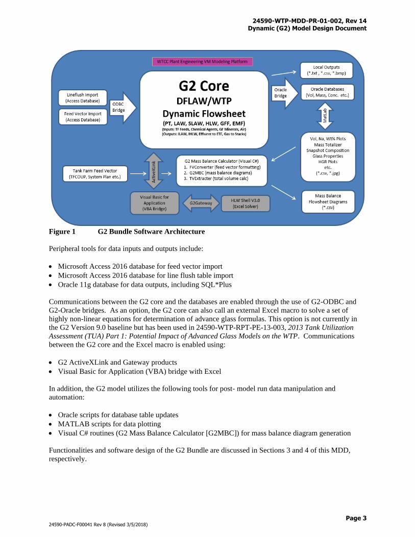
The Dynamic (G2) Model consists of a G2 core and a set of peripheral tools as shown in Figure 1. The
G2 core is developed using the Gensym G2 software development platform as required by the WTP
contract (noted that the Dynamic (G2) Model is not to be confused with the Gensym G2 software
development platform, where the former is the dynamic flowsheet and the latter is the programming tool
used to build the dynamic flowsheet). Details of the contractual and functional requirements are
summarized in the Dynamic (G2) Flowsheet Version 9.0 Life Cycle Document (24590-WTP-SWLCD-
PENG-17-0031). Due to the scale and size of data to and from the G2 core, peripheral tools are
developed to support the G2 core operations, including data inputs and outputs, access to external solver
for numerical solutions, and post- model run data manipulation. For software quality control purpose, the
G2 core and its peripheral tools are also referred to as the G2 Bundle as they are planned, upgraded,
tested, deployed, and managed following the same procedures and guides.
24590-WTP-MDD-PR-01-002, Rev 14 Dynamic (G2) Model Design Document
Page 3
24590-PADC-F00041 Rev 8 (Revised 3/5/2018)
Figure 1 G2 Bundle Software Architecture
Peripheral tools for data inputs and outputs include:
Microsoft Access 2016 database for feed vector import
Microsoft Access 2016 database for line flush table import
Oracle 11g database for data outputs, including SQL*Plus
Communications between the G2 core and the databases are enabled through the use of G2-ODBC and
G2-Oracle bridges. As an option, the G2 core can also call an external Excel macro to solve a set of
highly non-linear equations for determination of advance glass formulas. This option is not currently in
the G2 Version 9.0 baseline but has been used in 24590-WTP-RPT-PE-13-003, 2013 Tank Utilization
Assessment (TUA) Part 1: Potential Impact of Advanced Glass Models on the WTP. Communications
between the G2 core and the Excel macro is enabled using:
G2 ActiveXLink and Gateway products
Visual Basic for Application (VBA) bridge with Excel
In addition, the G2 model utilizes the following tools for post- model run data manipulation and
automation:
Oracle scripts for database table updates
MATLAB scripts for data plotting
Visual C# routines (G2 Mass Balance Calculator [G2MBC]) for mass balance diagram generation
Functionalities and software design of the G2 Bundle are discussed in Sections 3 and 4 of this MDD,
respectively.
24590-WTP-MDD-PR-01-002, Rev 14 Dynamic (G2) Model Design Document
Page 4
24590-PADC-F00041 Rev 8 (Revised 3/5/2018)
2.3 Life Cycle Documents
The upgrade to Dynamic (G2) Model Version 9.0 is governed by the following software quality
procedures and guides:
Life Cycle Control of “Level E” Process Models (24590-WTP-GPP-RAEN-EN-0028)
Run Requests and Change Requests for Process Models (24590-WTP-GPG-PENG-0005)
Naming Conventions for Version Control of Level E Process Models(24590-WTP-GPG-PENG-
00006)
Systems Design for Process Modeling (24590-WTP-PL-TE-01-008)
Life cycle documents that are applicable to the upgrade include:
Software Life Cycle Summary (24590-WTP-SWLCD-PENG-17-0034-01)
Flowsheet Bases, Assumptions, and Requirements (24590-WTP-RPT-PT-02-005)
LAW Melter Downtime Effects (24590-WTP-MCR-PENG-17-0001)
DFLAW Addition to G2 Flowsheet (24590-WTP-MCR-PENG-17-0014)
Startup Commissioning of the DFLAW for G2 (24590-WTP-MCR-PENG-17-0015)
Oracle and Matlab Scripts Upgrade for G2 Version 9.0 (24590-WTP-MCR-PENG-17-0016)
Dynamic (G2) Flowsheet Version 9.0 Life Cycle Document (24590-WTP-SWLCD-PENG-17-0031)
Dynamic (G2) Model Design Document (24590-WTP-MDD-PR-01-002)
Dynamic (G2) Flowsheet (24590-WTP-PSRA-PENG-15-0010)
In addition to simulating the baseline flowsheet, the Dynamic (G2) Model may be used to simulate
alternative DFLAW/WTP designs and operations. Any changes to the DFLAW/WTP baseline model will
be documented in scenario specific Model Run Request (MRQ) and Model Run Report (MRR).
2.4 Configuration Management
The Dynamic (G2) Flowsheet Version 9.0 model files are locked down in the data repository as required
by the Life Cycle Control of “Level E” Process Models (24590-WTP-GPP-RAEN-EN-0028). The model
files are also submitted to the PADC for permanent data records. Refer to Appendix Q for a list of the
baseline model files including their names, dates modified, types, and sizes.
24590-WTP-MDD-PR-01-002, Rev 14 Dynamic (G2) Model Design Document
Page 5
24590-PADC-F00041 Rev 8 (Revised 3/5/2018)
3 Model System Description
3.1 Time Steps and Dynamic Material Balance
The Dynamic (G2) Model performs discrete-time material balance calculations over the DFLAW/WTP
based on prescribed initial conditions, boundary conditions, and operating logic. The time steps are set
small enough to preserve the resolution of plant operations and large enough to avoid an unacceptably
long model run time. A 6-minute time step (i.e., every simulation clock tick represents 1/10 of a
simulated hour) is applied to the entire model except the Glass Former Reagent (GFR) System where a 1-
minute time step (every clock tick represents 1/60 of a simulated hour) is utilized. The 1-minute time step
in the GFR is needed due to the large flowrates and small sizes of the weigh stations and transporters.
Material balance is achieved by tracking the storage, pumping, separation, reaction, and phase change of
chemical components in every unit operation over each time increment. Each unit operation is event
driven as the status of that unit operation changes from time to time. An analyzer logic procedure
controls the actions of each unit operation using pump procedures, reaction procedures, sample
procedures, or other action procedures as appropriate depending on the current status of that unit
operation. The simulation clocks are used to synchronize the actions of all the processes.
3.2 Feed Vector
The Dynamic (G2) Model processes a feed vector that is created by the Tank Farm Contractor (TFC) and
provided by the DOE-ORP. The feed vector consists of a waste quantity file and a leach factor file. The
waste quantity file contains the batch names, proposed delivery dates, envelope types of the batches, and
the quantities of liquid and solid components (in units of kg-moles) of the Hanford Tank Farm wastes.
The leach factor file contains the leach factors for the constituents that will be dissolved during caustic
leach processes. Currently, ten solid constituents, including Al+3, Bi+3, Ca+2, Cr(Total), Fe+3, Na+, PO4-3,
Si+4, U (all isotopes), and SO4-2, can be leached in the Dynamic (G2) Model (Note: leach factors for Al+3
and PO4-3 are not used in the model as the leaching of Al(OH)3 and “soft” PO4
-3 is driven by solubility
correlations. The Al(OH)3 and “soft” PO4-3 solubility correlations are presented in Section 3.7.16).
WTCC Plant Engineering personnel modify the TFC feed vectors to form components specific to the
DFLAW/WTP operations. These components must be added to the feed vector arrays before the feeds
enter the plant (Table I-1). Typically, the components are created in a manner that maintains the feed
vector’s charge balance. Another modification to the TFC feed vector is the following application of
secular equilibrium rules for 137m-Ba and 90-Y (kg-moles):
137m-Ba = 1.526e-7 * 137-Cs (Eq. 1)
90-Y = 2.54e-4 * 90-Sr (Eq. 2)
Appendix I provides further discussions regarding the feed vector operations.
After modifications have been made to the TFC feed vector, it is imported to the G2 model from an
Access database through the ODBC bridge and is saved as part of the MRQ specific KB files. The feed
vectors are updated periodically as a result of DOE-ORP studies intended to optimize the operations at
both the Tank Farm and the WTP, or as the result of other studies. The default in the Dynamic (G2)
Model Version 9.0 is:
24590-WTP-MDD-PR-01-002, Rev 14 Dynamic (G2) Model Design Document
Page 6
24590-PADC-F00041 Rev 8 (Revised 3/5/2018)
1) Tuning #4, Simulant #64mod, and AP-105 Hot Feed for commissioning phase (refer to Appendix P
for details)
2) DFLAW feed with 100% recycle, e.g., no return to the Tank Farms (MMR-50056-8.1-8.3r1-2015-06-
25-at-06-35-09, RPP-40149-Vol2, Rev 3)
3.3 Equipment Initialization
Some equipment must be filled with chemical reagents before they can be utilized. These include: (noted
that PT/HLW/SLAW equipment are inactive in G2 Version 9.0)
1) Ultrafiltration post-isolation valve pipes (UFP-02A-P2, UFP-02B-P2)
2) Cesium Reagent Vessel (CXP-VSL-00005)
3) Cesium Ion Exchange (CXP) Columns (CXP-IXC-00001/2/3/4)
4) Cesium Nitric Acid Recovery (CNP) Evaporator (CNP-EVAP-00001)
5) Cesium Resin Addition (CRP) Vessel (CRP-VSL-00001)
6) Recovered Nitric Acid Vessel (CNP-VSL-00004)
7) Spent Resin Slurry Vessel (RDP-VSL-00002A)
8) LAW Submerged Bed Scrubbers (SBS) (LOP-SCB-00001/2)
9) HLW SBS (HOP-SCB-00001/2)
10) Vessel Vent Caustic Scrubber (PVP-SCB-00002)
11) Silica Storage Silo (GFR-TK-00001)
12) Zinc Oxide Storage Silo (GFR-TK-00002)
13) Titanium Dioxide Storage Silo (GFR-TK-00003)
14) Ferric Oxide Storage Silo (GFR-TK-00004)
15) Zirconium Silicate Sand Storage Silo (GFR-TK-00005)
16) Lithium Carbonate Storage Silo (GFR-TK-00006)
17) Boric Acid Storage Silo (GFR-TK-00007)
18) Aluminum Silicate Storage Silo (GFR-TK-00008)
19) Magnesium Silicate Storage Silo (GFR-TK-00009)
20) Calcium Silicate Storage Silo (GFR-TK-00010)
21) Sucrose Storage Silo (GFR-TK-00011)
22) Sodium Carbonate Storage Silo (GFR-TK-00012)
23) Borax Storage Silo (GFR-TK-00028)
24) Balance of Facilities (BOF)
Initialization of the DFLAW process equipment are discussed in Appendix P.
Reagents for the DFLAW/WTP chemical processes are assumed to be readily available in the BOF before
startup. Reagent types, volumes, and concentrations of the BOF utilized in the G2 model are presented in
Appendix B. Reagent types, volumes, and concentrations added to the equipment listed above during
model initialization are discussed in related sub-sections under Section 3.8.
24590-WTP-MDD-PR-01-002, Rev 14 Dynamic (G2) Model Design Document
Page 7
24590-PADC-F00041 Rev 8 (Revised 3/5/2018)
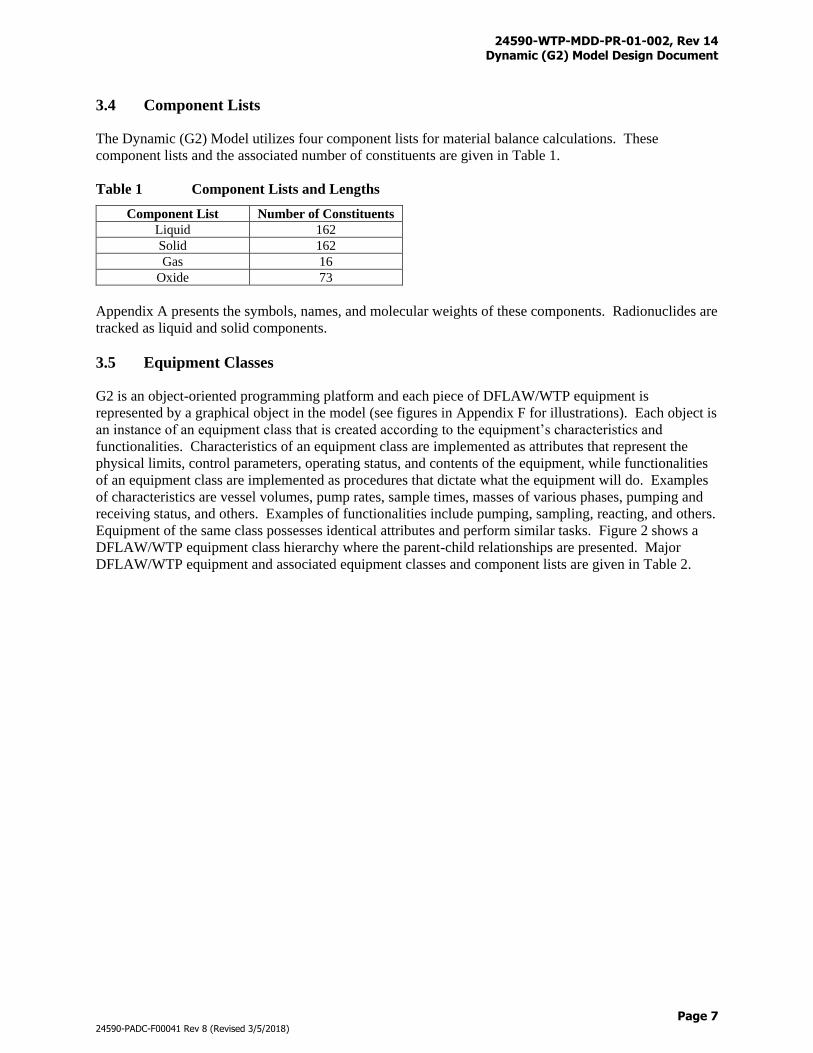
3.4 Component Lists
The Dynamic (G2) Model utilizes four component lists for material balance calculations. These
component lists and the associated number of constituents are given in Table 1.
Table 1 Component Lists and Lengths
Component List Number of Constituents
Liquid 162
Solid 162
Gas 16
Oxide 73
Appendix A presents the symbols, names, and molecular weights of these components. Radionuclides are
tracked as liquid and solid components.
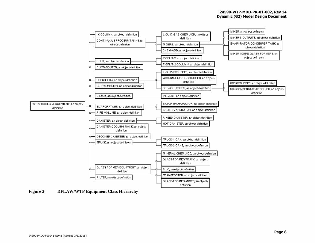
3.5 Equipment Classes
G2 is an object-oriented programming platform and each piece of DFLAW/WTP equipment is
represented by a graphical object in the model (see figures in Appendix F for illustrations). Each object is
an instance of an equipment class that is created according to the equipment’s characteristics and
functionalities. Characteristics of an equipment class are implemented as attributes that represent the
physical limits, control parameters, operating status, and contents of the equipment, while functionalities
of an equipment class are implemented as procedures that dictate what the equipment will do. Examples
of characteristics are vessel volumes, pump rates, sample times, masses of various phases, pumping and
receiving status, and others. Examples of functionalities include pumping, sampling, reacting, and others.
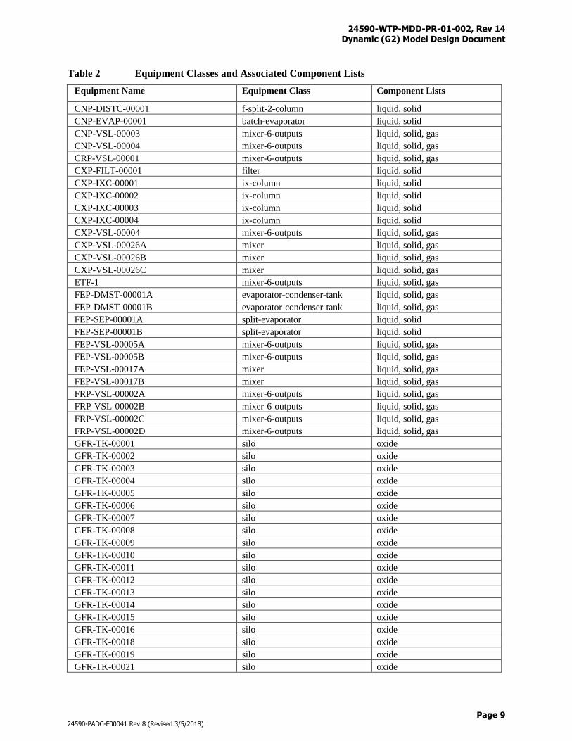
Equipment of the same class possesses identical attributes and perform similar tasks. Figure 2 shows a
DFLAW/WTP equipment class hierarchy where the parent-child relationships are presented. Major
DFLAW/WTP equipment and associated equipment classes and component lists are given in Table 2.
24590-WTP-MDD-PR-01-002, Rev 14 Dynamic (G2) Model Design Document
Page 8
24590-PADC-F00041 Rev 8 (Revised 3/5/2018)
Figure 2 DFLAW/WTP Equipment Class Hierarchy
24590-WTP-MDD-PR-01-002, Rev 14 Dynamic (G2) Model Design Document
Page 9
24590-PADC-F00041 Rev 8 (Revised 3/5/2018)
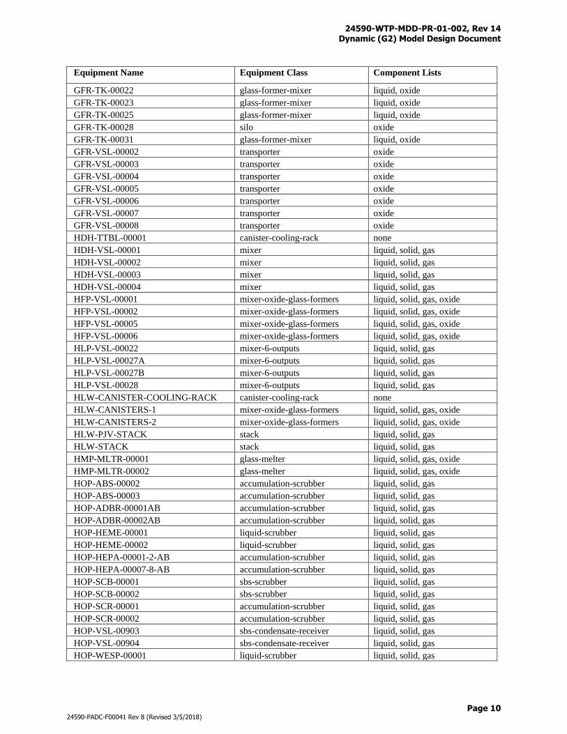
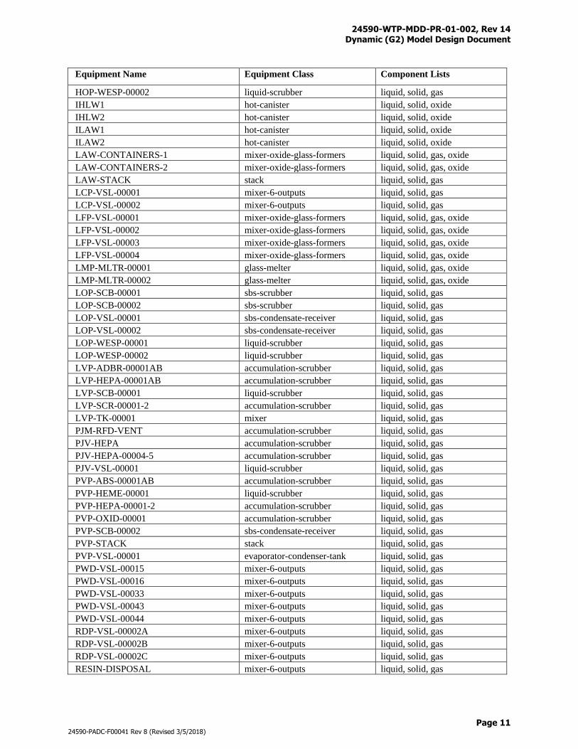
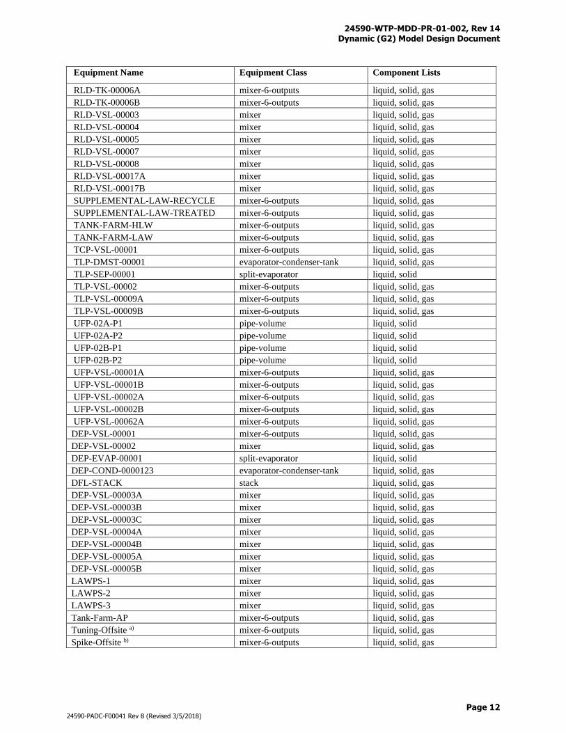
Table 2 Equipment Classes and Associated Component Lists
Equipment Name Equipment Class Component Lists
CNP-DISTC-00001 f-split-2-column liquid, solid
CNP-EVAP-00001 batch-evaporator liquid, solid
CNP-VSL-00003 mixer-6-outputs liquid, solid, gas
CNP-VSL-00004 mixer-6-outputs liquid, solid, gas
CRP-VSL-00001 mixer-6-outputs liquid, solid, gas
CXP-FILT-00001 filter liquid, solid
CXP-IXC-00001 ix-column liquid, solid
CXP-IXC-00002 ix-column liquid, solid
CXP-IXC-00003 ix-column liquid, solid
CXP-IXC-00004 ix-column liquid, solid
CXP-VSL-00004 mixer-6-outputs liquid, solid, gas
CXP-VSL-00026A mixer liquid, solid, gas
CXP-VSL-00026B mixer liquid, solid, gas
CXP-VSL-00026C mixer liquid, solid, gas
ETF-1 mixer-6-outputs liquid, solid, gas
FEP-DMST-00001A evaporator-condenser-tank liquid, solid, gas
FEP-DMST-00001B evaporator-condenser-tank liquid, solid, gas
FEP-SEP-00001A split-evaporator liquid, solid
FEP-SEP-00001B split-evaporator liquid, solid
FEP-VSL-00005A mixer-6-outputs liquid, solid, gas
FEP-VSL-00005B mixer-6-outputs liquid, solid, gas
FEP-VSL-00017A mixer liquid, solid, gas
FEP-VSL-00017B mixer liquid, solid, gas
FRP-VSL-00002A mixer-6-outputs liquid, solid, gas
FRP-VSL-00002B mixer-6-outputs liquid, solid, gas
FRP-VSL-00002C mixer-6-outputs liquid, solid, gas
FRP-VSL-00002D mixer-6-outputs liquid, solid, gas
GFR-TK-00001 silo oxide
GFR-TK-00002 silo oxide
GFR-TK-00003 silo oxide
GFR-TK-00004 silo oxide
GFR-TK-00005 silo oxide
GFR-TK-00006 silo oxide
GFR-TK-00007 silo oxide
GFR-TK-00008 silo oxide
GFR-TK-00009 silo oxide
GFR-TK-00010 silo oxide
GFR-TK-00011 silo oxide
GFR-TK-00012 silo oxide
GFR-TK-00013 silo oxide
GFR-TK-00014 silo oxide
GFR-TK-00015 silo oxide
GFR-TK-00016 silo oxide
GFR-TK-00018 silo oxide
GFR-TK-00019 silo oxide
GFR-TK-00021 silo oxide
24590-WTP-MDD-PR-01-002, Rev 14 Dynamic (G2) Model Design Document
Page 10
24590-PADC-F00041 Rev 8 (Revised 3/5/2018)
Equipment Name Equipment Class Component Lists
GFR-TK-00022 glass-former-mixer liquid, oxide
GFR-TK-00023 glass-former-mixer liquid, oxide
GFR-TK-00025 glass-former-mixer liquid, oxide
GFR-TK-00028 silo oxide
GFR-TK-00031 glass-former-mixer liquid, oxide
GFR-VSL-00002 transporter oxide
GFR-VSL-00003 transporter oxide
GFR-VSL-00004 transporter oxide
GFR-VSL-00005 transporter oxide
GFR-VSL-00006 transporter oxide
GFR-VSL-00007 transporter oxide
GFR-VSL-00008 transporter oxide
HDH-TTBL-00001 canister-cooling-rack none
HDH-VSL-00001 mixer liquid, solid, gas
HDH-VSL-00002 mixer liquid, solid, gas
HDH-VSL-00003 mixer liquid, solid, gas
HDH-VSL-00004 mixer liquid, solid, gas
HFP-VSL-00001 mixer-oxide-glass-formers liquid, solid, gas, oxide
HFP-VSL-00002 mixer-oxide-glass-formers liquid, solid, gas, oxide
HFP-VSL-00005 mixer-oxide-glass-formers liquid, solid, gas, oxide
HFP-VSL-00006 mixer-oxide-glass-formers liquid, solid, gas, oxide
HLP-VSL-00022 mixer-6-outputs liquid, solid, gas
HLP-VSL-00027A mixer-6-outputs liquid, solid, gas
HLP-VSL-00027B mixer-6-outputs liquid, solid, gas
HLP-VSL-00028 mixer-6-outputs liquid, solid, gas
HLW-CANISTER-COOLING-RACK canister-cooling-rack none
HLW-CANISTERS-1 mixer-oxide-glass-formers liquid, solid, gas, oxide
HLW-CANISTERS-2 mixer-oxide-glass-formers liquid, solid, gas, oxide
HLW-PJV-STACK stack liquid, solid, gas
HLW-STACK stack liquid, solid, gas
HMP-MLTR-00001 glass-melter liquid, solid, gas, oxide
HMP-MLTR-00002 glass-melter liquid, solid, gas, oxide
HOP-ABS-00002 accumulation-scrubber liquid, solid, gas
HOP-ABS-00003 accumulation-scrubber liquid, solid, gas
HOP-ADBR-00001AB accumulation-scrubber liquid, solid, gas
HOP-ADBR-00002AB accumulation-scrubber liquid, solid, gas
HOP-HEME-00001 liquid-scrubber liquid, solid, gas
HOP-HEME-00002 liquid-scrubber liquid, solid, gas
HOP-HEPA-00001-2-AB accumulation-scrubber liquid, solid, gas
HOP-HEPA-00007-8-AB accumulation-scrubber liquid, solid, gas
HOP-SCB-00001 sbs-scrubber liquid, solid, gas
HOP-SCB-00002 sbs-scrubber liquid, solid, gas
HOP-SCR-00001 accumulation-scrubber liquid, solid, gas
HOP-SCR-00002 accumulation-scrubber liquid, solid, gas
HOP-VSL-00903 sbs-condensate-receiver liquid, solid, gas
HOP-VSL-00904 sbs-condensate-receiver liquid, solid, gas
HOP-WESP-00001 liquid-scrubber liquid, solid, gas
24590-WTP-MDD-PR-01-002, Rev 14 Dynamic (G2) Model Design Document
Page 11
24590-PADC-F00041 Rev 8 (Revised 3/5/2018)
Equipment Name Equipment Class Component Lists
HOP-WESP-00002 liquid-scrubber liquid, solid, gas
IHLW1 hot-canister liquid, solid, oxide
IHLW2 hot-canister liquid, solid, oxide
ILAW1 hot-canister liquid, solid, oxide
ILAW2 hot-canister liquid, solid, oxide
LAW-CONTAINERS-1 mixer-oxide-glass-formers liquid, solid, gas, oxide
LAW-CONTAINERS-2 mixer-oxide-glass-formers liquid, solid, gas, oxide
LAW-STACK stack liquid, solid, gas
LCP-VSL-00001 mixer-6-outputs liquid, solid, gas
LCP-VSL-00002 mixer-6-outputs liquid, solid, gas
LFP-VSL-00001 mixer-oxide-glass-formers liquid, solid, gas, oxide
LFP-VSL-00002 mixer-oxide-glass-formers liquid, solid, gas, oxide
LFP-VSL-00003 mixer-oxide-glass-formers liquid, solid, gas, oxide
LFP-VSL-00004 mixer-oxide-glass-formers liquid, solid, gas, oxide
LMP-MLTR-00001 glass-melter liquid, solid, gas, oxide
LMP-MLTR-00002 glass-melter liquid, solid, gas, oxide
LOP-SCB-00001 sbs-scrubber liquid, solid, gas
LOP-SCB-00002 sbs-scrubber liquid, solid, gas
LOP-VSL-00001 sbs-condensate-receiver liquid, solid, gas
LOP-VSL-00002 sbs-condensate-receiver liquid, solid, gas
LOP-WESP-00001 liquid-scrubber liquid, solid, gas
LOP-WESP-00002 liquid-scrubber liquid, solid, gas
LVP-ADBR-00001AB accumulation-scrubber liquid, solid, gas
LVP-HEPA-00001AB accumulation-scrubber liquid, solid, gas
LVP-SCB-00001 liquid-scrubber liquid, solid, gas
LVP-SCR-00001-2 accumulation-scrubber liquid, solid, gas
LVP-TK-00001 mixer liquid, solid, gas
PJM-RFD-VENT accumulation-scrubber liquid, solid, gas
PJV-HEPA accumulation-scrubber liquid, solid, gas
PJV-HEPA-00004-5 accumulation-scrubber liquid, solid, gas
PJV-VSL-00001 liquid-scrubber liquid, solid, gas
PVP-ABS-00001AB accumulation-scrubber liquid, solid, gas
PVP-HEME-00001 liquid-scrubber liquid, solid, gas
PVP-HEPA-00001-2 accumulation-scrubber liquid, solid, gas
PVP-OXID-00001 accumulation-scrubber liquid, solid, gas
PVP-SCB-00002 sbs-condensate-receiver liquid, solid, gas
PVP-STACK stack liquid, solid, gas
PVP-VSL-00001 evaporator-condenser-tank liquid, solid, gas
PWD-VSL-00015 mixer-6-outputs liquid, solid, gas
PWD-VSL-00016 mixer-6-outputs liquid, solid, gas
PWD-VSL-00033 mixer-6-outputs liquid, solid, gas
PWD-VSL-00043 mixer-6-outputs liquid, solid, gas
PWD-VSL-00044 mixer-6-outputs liquid, solid, gas
RDP-VSL-00002A mixer-6-outputs liquid, solid, gas
RDP-VSL-00002B mixer-6-outputs liquid, solid, gas
RDP-VSL-00002C mixer-6-outputs liquid, solid, gas
RESIN-DISPOSAL mixer-6-outputs liquid, solid, gas
24590-WTP-MDD-PR-01-002, Rev 14 Dynamic (G2) Model Design Document
Page 12
24590-PADC-F00041 Rev 8 (Revised 3/5/2018)
Equipment Name Equipment Class Component Lists
RLD-TK-00006A mixer-6-outputs liquid, solid, gas
RLD-TK-00006B mixer-6-outputs liquid, solid, gas
RLD-VSL-00003 mixer liquid, solid, gas
RLD-VSL-00004 mixer liquid, solid, gas
RLD-VSL-00005 mixer liquid, solid, gas
RLD-VSL-00007 mixer liquid, solid, gas
RLD-VSL-00008 mixer liquid, solid, gas
RLD-VSL-00017A mixer liquid, solid, gas
RLD-VSL-00017B mixer liquid, solid, gas
SUPPLEMENTAL-LAW-RECYCLE mixer-6-outputs liquid, solid, gas
SUPPLEMENTAL-LAW-TREATED mixer-6-outputs liquid, solid, gas
TANK-FARM-HLW mixer-6-outputs liquid, solid, gas
TANK-FARM-LAW mixer-6-outputs liquid, solid, gas
TCP-VSL-00001 mixer-6-outputs liquid, solid, gas
TLP-DMST-00001 evaporator-condenser-tank liquid, solid, gas
TLP-SEP-00001 split-evaporator liquid, solid
TLP-VSL-00002 mixer-6-outputs liquid, solid, gas
TLP-VSL-00009A mixer-6-outputs liquid, solid, gas
TLP-VSL-00009B mixer-6-outputs liquid, solid, gas
UFP-02A-P1 pipe-volume liquid, solid
UFP-02A-P2 pipe-volume liquid, solid
UFP-02B-P1 pipe-volume liquid, solid
UFP-02B-P2 pipe-volume liquid, solid
UFP-VSL-00001A mixer-6-outputs liquid, solid, gas
UFP-VSL-00001B mixer-6-outputs liquid, solid, gas
UFP-VSL-00002A mixer-6-outputs liquid, solid, gas
UFP-VSL-00002B mixer-6-outputs liquid, solid, gas
UFP-VSL-00062A mixer-6-outputs liquid, solid, gas
DEP-VSL-00001 mixer-6-outputs liquid, solid, gas
DEP-VSL-00002 mixer liquid, solid, gas
DEP-EVAP-00001 split-evaporator liquid, solid
DEP-COND-0000123 evaporator-condenser-tank liquid, solid, gas
DFL-STACK stack liquid, solid, gas
DEP-VSL-00003A mixer liquid, solid, gas
DEP-VSL-00003B mixer liquid, solid, gas
DEP-VSL-00003C mixer liquid, solid, gas
DEP-VSL-00004A mixer liquid, solid, gas
DEP-VSL-00004B mixer liquid, solid, gas
DEP-VSL-00005A mixer liquid, solid, gas
DEP-VSL-00005B mixer liquid, solid, gas
LAWPS-1 mixer liquid, solid, gas
LAWPS-2 mixer liquid, solid, gas
LAWPS-3 mixer liquid, solid, gas
Tank-Farm-AP mixer-6-outputs liquid, solid, gas
Tuning-Offsite a) mixer-6-outputs liquid, solid, gas
Spike-Offsite b) mixer-6-outputs liquid, solid, gas
24590-WTP-MDD-PR-01-002, Rev 14 Dynamic (G2) Model Design Document
Page 13
24590-PADC-F00041 Rev 8 (Revised 3/5/2018)
a) An infinitely large virtual tank that represents an offsite treatment facility for effluents generated during
the tuning material runs. b) An infinitely large virtual tank that represents an offsite treatment facility for effluents generated during
the spike runs.
3.6 Volume Calculations
The volume of material in a unit operation is calculated by analyzing the amount and types of components
in the unit’s component array. In most cases, the total volume involves the partial volumes of liquid and
solid, but in some unit operations it also possesses the contribution from oxides. In equipment where
oxide exists, its volume is added to the solid volume. Gas components exist in the form of mass in some
equipment and do not contribute to the total volume of the equipment.
A liquid’s SpG is calculated by summing the mass of all the dissolved constituents in the volume defined
for the solution, calculating the weight percent, and then estimating the density from a correlation derived
from NaOH and NaNO3 dissolved in water (Equations 3 and 4). Using the liquid SpG, a volume for the
liquid components is obtained.
SpG = 0.00935 X + 0.996 if X > 0 (Eq. 3).
SpG = 1.0 if X 0 (Eq. 4)
Where:
SpG = specific gravity of a solution (dimensionless)
X =
100
)(
)(
iliquid
waterliquidiliquid(dimensionless)
liquid = liquid components in the solution (kg)
i = 0 to 161
This SpG correlation applies to every process equipment that requires the calculation of liquid volume
except the Cesium Evaporator Separator Vessel (CNP-EVAP-00001), where a ternary correlation of
HNO3, NaNO3, and H2O is utilized. Details of the CNP-EVAP-00001 SpG correlation are discussed in
Section 3.8.5.
The solid and oxide components have constant density values. The overall density for solids is
approximated at 3.0 grams per cubic centimeter (g/cm3). The LAW glass density is set at 2.58 g/cm3
while the HLW glass density is set at 2.66 g/cm3. Using the constant densities, the volumes of solids and
oxides are determined.
3.7 Common Operating Rules
There are operating rules/programming conventions that are used repeatedly throughout the model. The
purpose of this section is to document these common operating rules used in the development of the
Dynamic (G2) Model so that recurring discussions are not needed for the unit operations. The most
prevalent operating rules used in the model are specified in the following subsections.
3.7.1 Basic Model Rules
Liquid, solid, oxide, and gas components, in kg-moles, are tracked in the model using component arrays.
Each unit operation (vessel, evaporator, column, scrubber, melter, condenser, etc.) has its own component
24590-WTP-MDD-PR-01-002, Rev 14 Dynamic (G2) Model Design Document
Page 14
24590-PADC-F00041 Rev 8 (Revised 3/5/2018)
arrays which contain the components at that time. When material is transferred out of the unit, the
amount of material to be removed in that time step is calculated using a floating-point data type that has a
16-digit precision. This amount of material is: a) subtracted from component arrays of the unit that is
emptying; and b) added to component arrays of the unit that is filling. This ensures a conservation of
mass within the model.
Feed-lists and output-lists are used for the determination of batch transfers. When an upstream unit is
ready to transfer material out, the unit is placed on its output-list. When a downstream unit is ready to
receive material, it is placed on its feed-list. The upstream analyzer logic procedure constantly scans for
the status of both lists and triggers the upstream unit pump procedure for pumping when it discovers that
both upstream and downstream units are ready. This methodology ensures that unwanted transfers do
not occur. Multiple feed-lists and/or output-lists may exist for vessels having multiple inflow sources
and/or outflow destinations, respectively.
When the unit transfers material, it transfers a fraction of kg-moles from the component arrays based on
the fraction of the unit’s volume that needs to be transferred. The fraction is constrained by the pump rate
of the upstream unit, the remaining volume of the upstream unit that can be pumped, and the remaining
space of the downstream unit that can be filled.
There are exceptions in some vessels where they can be emptied and filled at the same time. There are
also exceptions in some vessels where contingency volumes exist such that the vessel can receive if it
needs to and discharge if the downstream unit becomes available. These exceptions are discussed as
appropriate in detail in Section 3.8.
3.7.2 Batch Operations
Batch operations are the most commonly used vessel operations in the dynamic model. When the
upstream vessel is full or reaches its pre-assigned setpoint, the upstream vessel is placed on its output-list.
When the downstream vessel is empty or reaches its minimum volume, the vessel is placed on its
input-list. The analyzer logic of the upstream vessel confirms that both vessels are ready. If there are no
other conditions or control logic preventing the transfer, the transfer begins and the contents of the
upstream vessel are transferred to the downstream vessel. The transfer volume is calculated for each 6-
minute, or 1-minute as appropriate, time-step by taking the minimum of the following:
1) the volume available to pump from the upstream vessel
2) the volume available to receive in the downstream vessel, and
3) the capacity of the pump
After each time-step transfer, both the upstream and downstream vessel volumes are updated, along with
the vessel component arrays. The volumes of both vessels are checked again and either triggered to
continue transferring or triggered to stop transferring because the volume constraints have been met. The
batch transfer is terminated when the upstream vessel reaches its minimum volume or the downstream
vessel reaches either its setpoint or maximum volume. Refer to Section 3.7.15 for volume definitions.
Transfer lines do not have volumes in the model so that materials out of the upstream vessels equal to
materials into the downstream vessels. However, actual transfer line volumes are used externally when
line flush volumes are calculated. Line flush volumes are provided in Table H-1.
Exceptions exist for the ultrafiltration filter loops where the transfer lines contain volumes, and flushing
efficiencies are applied during power flush operations. Section 3.8.3 provides detailed discussions of the
ultrafiltration filter loops.
24590-WTP-MDD-PR-01-002, Rev 14 Dynamic (G2) Model Design Document
Page 15
24590-PADC-F00041 Rev 8 (Revised 3/5/2018)
3.7.3 Continuous Operations
Continuous operations are used primarily in the melters, offgas systems, and the evaporators, but is also
applied to the UFP-VSL-00002A/B vessels and the “Super Tank” (Note: “Super Tank” is the modeling
simplification that combines the functions of UFP-VSL-00062A/B/C and CXP-VSL-00004). In a
continuous operation, material enters the unit, reactions and/or splits take place, and exits the unit all in
one time-step.
Some operations can be described as semi-continuous operations because they accumulate some of the
material that continuously passes through and eventually empty the gathered material in a batch transfer.
The Cesium Nitric Acid Recovery Evaporator, Submerged Bed Scrubbers, and Caustic Scrubbers are
examples of semi-continuous operations.
3.7.4 Action Modes of Vessels
Most of the process vessels operate in six action modes, “Empty”, “Fill”, “Filling”, “Sampling”,
“Empty-Now”, “Emptying”. Definitions for these action modes are given below:
“Empty” = A vessel is empty or at minimum volume
“Fill” = A vessel is waiting to be filled
“Filling” = A vessel is currently being filled
“Sampling” = A vessel is being sampled
“Empty-Now” = A vessel is waiting to be emptied
“Emptying” = A vessel is currently being emptied
The less common operation modes used in the model are not discussed in this MDD but can be obtained
from the G2 codes. A vessel can only be filled when it is in the “Empty” or “Fill” modes. Only one
source can be pumped into a vessel at a time. Exception exists in some vessels where they can be filled
and emptied at the same time. Exception also exists in some vessels where contingency volume is
utilized (e.g., a vessel can either be filled or discharged when it is in the contingency zone, depending on
the conditions of the upstream or downstream vessels). Contingency volume is discussed in Section
3.7.5. Details of these exceptions are discussed as appropriate in Section 3.8.
3.7.5 Contingency Volume
Some vessels have multiple setpoint controls and contingency volumes. These vessels operate between
the minimum and maximum volumes with two setpoints in between. A contingency vessel can be filled,
and then continue to be filled until the current batch (after being completely transferred in) raises the
volume to or above setpoint #1. The mode of the contingency vessel is then changed to “Continuous”. If
the downstream vessel is not ready to receive a transfer, the contingency vessel continues to be filled until
the volume is at, or above, setpoint #2, then the mode of the contingency vessel is changed to “Empty-
Now”. The contingency volume is set between setpoint #1 and the setpoint #2. The contingency vessel
can be emptied any time when it is in the contingency zone and the downstream vessel is available.
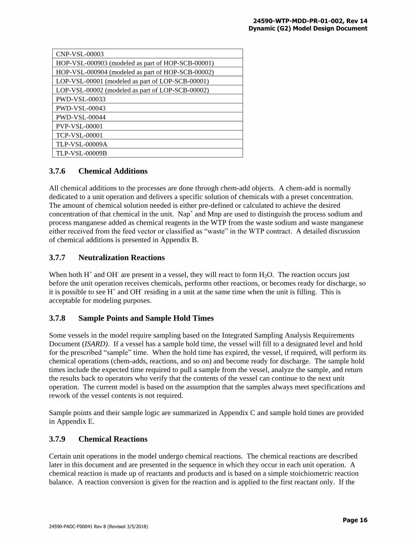
The list below provides the names of contingency vessels which are further discussed in Section 3.8 as
appropriate.
24590-WTP-MDD-PR-01-002, Rev 14 Dynamic (G2) Model Design Document
Page 16
24590-PADC-F00041 Rev 8 (Revised 3/5/2018)
CNP-VSL-00003
HOP-VSL-000903 (modeled as part of HOP-SCB-00001)
HOP-VSL-000904 (modeled as part of HOP-SCB-00002)
LOP-VSL-00001 (modeled as part of LOP-SCB-00001)
LOP-VSL-00002 (modeled as part of LOP-SCB-00002)
PWD-VSL-00033
PWD-VSL-00043
PWD-VSL-00044
PVP-VSL-00001
TCP-VSL-00001
TLP-VSL-00009A
TLP-VSL-00009B
3.7.6 Chemical Additions
All chemical additions to the processes are done through chem-add objects. A chem-add is normally
dedicated to a unit operation and delivers a specific solution of chemicals with a preset concentration.
The amount of chemical solution needed is either pre-defined or calculated to achieve the desired
concentration of that chemical in the unit. Nap+ and Mnp are used to distinguish the process sodium and
process manganese added as chemical reagents in the WTP from the waste sodium and waste manganese
either received from the feed vector or classified as “waste” in the WTP contract. A detailed discussion
of chemical additions is presented in Appendix B.
3.7.7 Neutralization Reactions
When both H+ and OH- are present in a vessel, they will react to form H2O. The reaction occurs just
before the unit operation receives chemicals, performs other reactions, or becomes ready for discharge, so
it is possible to see H+ and OH- residing in a unit at the same time when the unit is filling. This is
acceptable for modeling purposes.
3.7.8 Sample Points and Sample Hold Times
Some vessels in the model require sampling based on the Integrated Sampling Analysis Requirements
Document (ISARD). If a vessel has a sample hold time, the vessel will fill to a designated level and hold
for the prescribed “sample” time. When the hold time has expired, the vessel, if required, will perform its
chemical operations (chem-adds, reactions, and so on) and become ready for discharge. The sample hold
times include the expected time required to pull a sample from the vessel, analyze the sample, and return
the results back to operators who verify that the contents of the vessel can continue to the next unit
operation. The current model is based on the assumption that the samples always meet specifications and
rework of the vessel contents is not required.
Sample points and their sample logic are summarized in Appendix C and sample hold times are provided
in Appendix E.
3.7.9 Chemical Reactions
Certain unit operations in the model undergo chemical reactions. The chemical reactions are described
later in this document and are presented in the sequence in which they occur in each unit operation. A
chemical reaction is made up of reactants and products and is based on a simple stoichiometric reaction
balance. A reaction conversion is given for the reaction and is applied to the first reactant only. If the
24590-WTP-MDD-PR-01-002, Rev 14 Dynamic (G2) Model Design Document
Page 17
24590-PADC-F00041 Rev 8 (Revised 3/5/2018)
reaction cannot reach the desired conversion, then the reaction will continue until all of the limiting
reactant has been used up. The reaction subtracts the reactants used from the component array and adds
the products generated to the component array. If the reactions involve phase changes, reactants and
products are moved to the corresponding liquid/solid/gas/oxide positions in the arrays. Volume is
recalculated after the reactions.
3.7.10 Splits
Splits are used in the model to demonstrate the entrainment of components in certain processes and the
separation of components in other processes. Split factors are based on the decontamination factors (DFs)
of the unit operation, e.g., split to overhead = 1 / DF. Splits are performed in the evaporators, condensers,
melters, and offgas systems using either percent or fractions. The splits are component based and are
applied to the component array of the unit operation. The fraction or percent of that particular component
is subtracted from the component array of the unit operation performing the splits and added to the
component array designated by the split table. The remaining material in the unit operation performing
the split exits out of the other exit stream.
If the unit operation is an accumulation-scrubber (see Table 2 for equipment classes), the material that is
removed using the split is not transferred to another unit operation. Rather, it is added to an accumulating
array where captured material is stored. Components cannot be subtracted from the accumulating array,
only added to it.
The split factors for the unit operations applicable are summarized in Appendix D.
3.7.11 Primary and Secondary Process Waters
Many processes such as line flush, sodium dilution, solid wash, and oxidative wash require the use of
process waters. Process condensate from the Pretreatment Process Condensate Vessel
(RLD-TK-00006A) is the preferred source (primary source) if sufficient volume is available at the time
when it is needed. Process water is the secondary choice and is only used if the primary source is
unavailable or insufficient. The contents of process condensate change constantly as RLD-TK-00006A
receives condensates from the Waste Feed Evaporator Condensate Vessel and the Treated LAW
Evaporator Condensate Vessel where the feeds to the evaporators vary.
3.7.12 Inhibited Water
Inhibited water is used for line flushes before and after wastes are transferred to the WTP from the Tank
Farm. Inhibited water is also used for line flush into a UFP2 vessel after a UFP1 vessel empties its
contents entirely (i.e., reach the heel), for power flushing, and for flushing the lines from UFP2 to HLP-
VSL-00027A/B after solid discharge. Inhibited water is a mixed solution of 0.01M NapOH and 0.011M
NapNO2 (i.e., [Nap+] = 0.021M, [OH-] = 0.01M, and [NO2-] = 0.011M).
3.7.13 Line Flushes
Line flushes are applied to the Dynamic (G2) Flowsheet to mitigate: 1) precipitation of salts, 2) hydrogen
accumulation, and 3) plugging of process lines. The Interface Control Document (ICD) flushes are
conducted using inhibited water and include the lines from the Tank Farm to the HLP-VSL-00022 and
FRP-VSL-00002A/B/C/D vessels as discussed in the following.
24590-WTP-MDD-PR-01-002, Rev 14 Dynamic (G2) Model Design Document
Page 18
24590-PADC-F00041 Rev 8 (Revised 3/5/2018)
Tank Farm to HLP-VSL-00022
Prior to an HLW batch transfer, HLP-VSL-00022 receives 2,500 gallons of inhibited water.
HLP-VSL-00022 receives an additional 2,000 gallons of inhibited water after the Tank Farm batch
transfer is completed and before the vessel is sampled.
At the end of the post-transfer flush, PWD-VSL-00043 and PWD-VSL-00033 will simultaneously receive
2,900 gallons and 100 gallons of inhibited water, respectively. Due to the dynamic nature of the
flowsheet, PWD-VSL-00043 and PWD-VSL-00033 vessels could be in different operating modes when
flushing takes place. The flush water can only be pumped into the Plant Wash and Disposal System
(PWD) vessels when they are in the “empty” or “fill” modes, or otherwise be delayed.
Tank Farm to FRP-VSL-00002A/B/C/D
A LAW batch may fill one, two, or three Waste Feed Receipt Vessels depending on the size of the batch.
The 2,500 gallons of pre-transfer inhibited water will be sent to the first receiving vessel prior to the batch
delivery while the 2,000 gallons of post-transfer inhibited water will be sent to the last receiving vessel
prior to sampling.
At the end of the post-transfer flush, PWD-VSL-00043 and PWD-VSL-00033 will simultaneously receive
2,900 gallons and 100 gallons of inhibited water, respectively. The operating logic for PWD-VSL-00043
and PWD-VSL-00033 is the same as those discussed above.
The HPAV and line plugging flushes are conducted using process condensate (primary source) or process
water (secondly source) for Pretreatment vessels, however only process water can be used for flushes to
the LAW and HLW equipment. These line flush operations can be triggered by: 1) waste transfer, 2)
sampling, and 3) time. Transfer flushes are conducted after a waste batch transfer from the upstream tank
to the downstream tank; sampling flushes are made after a sample is pulled from the vessel; and time
flushes are carried out regularly at the specified time interval. In most cases, an origin of flush is
associated with multiple destinations of flushes as the results of dead legs and piping configurations. The
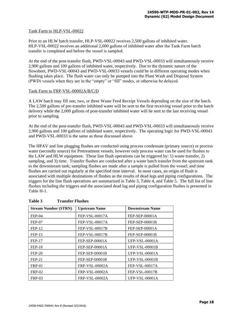
triggers for the line flush operations are summarized in Table 3, Table 4, and Table 5. The full list of line
flushes including the triggers and the associated dead lag and piping configuration flushes is presented in
Table H-1.
Table 3 Transfer Flushes
Stream Number (STRN) Upstream Name Downstream Name
FEP-04 FEP-VSL-00017A FEP-SEP-00001A
FEP-07 FEP-VSL-00017A FEP-SEP-00001B
FEP-12 FEP-VSL-00017B FEP-SEP-00001A
FEP-15 FEP-VSL-00017B FEP-SEP-00001B
FEP-17 FEP-SEP-00001A UFP-VSL-00001A
FEP-18 FEP-SEP-00001A UFP-VSL-00001B
FEP-20 FEP-SEP-00001B UFP-VSL-00001A
FEP-21 FEP-SEP-00001B UFP-VSL-00001B
FRP-01 FRP-VSL-00002A FEP-VSL-00017A
FRP-02 FRP-VSL-00002A FEP-VSL-00017B
FRP-03 FRP-VSL-00002A UFP-VSL-00001A
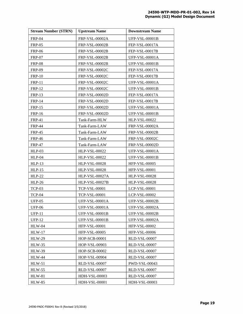
24590-WTP-MDD-PR-01-002, Rev 14 Dynamic (G2) Model Design Document
Page 19
24590-PADC-F00041 Rev 8 (Revised 3/5/2018)
Stream Number (STRN) Upstream Name Downstream Name
FRP-04 FRP-VSL-00002A UFP-VSL-00001B
FRP-05 FRP-VSL-00002B FEP-VSL-00017A
FRP-06 FRP-VSL-00002B FEP-VSL-00017B
FRP-07 FRP-VSL-00002B UFP-VSL-00001A
FRP-08 FRP-VSL-00002B UFP-VSL-00001B
FRP-09 FRP-VSL-00002C FEP-VSL-00017A
FRP-10 FRP-VSL-00002C FEP-VSL-00017B
FRP-11 FRP-VSL-00002C UFP-VSL-00001A
FRP-12 FRP-VSL-00002C UFP-VSL-00001B
FRP-13 FRP-VSL-00002D FEP-VSL-00017A
FRP-14 FRP-VSL-00002D FEP-VSL-00017B
FRP-15 FRP-VSL-00002D UFP-VSL-00001A
FRP-16 FRP-VSL-00002D UFP-VSL-00001B
FRP-41 Tank-Farm-HLW HLP-VSL-00022
FRP-44 Tank-Farm-LAW FRP-VSL-00002A
FRP-45 Tank-Farm-LAW FRP-VSL-00002B
FRP-46 Tank-Farm-LAW FRP-VSL-00002C
FRP-47 Tank-Farm-LAW FRP-VSL-00002D
HLP-03 HLP-VSL-00022 UFP-VSL-00001A
HLP-04 HLP-VSL-00022 UFP-VSL-00001B
HLP-13 HLP-VSL-00028 HFP-VSL-00005
HLP-15 HLP-VSL-00028 HFP-VSL-00001
HLP-22 HLP-VSL-00027A HLP-VSL-00028
HLP-26 HLP-VSL-00027B HLP-VSL-00028
TCP-03 TCP-VSL-00001 LCP-VSL-00001
TCP-04 TCP-VSL-00001 LCP-VSL-00002
UFP-05 UFP-VSL-00001A UFP-VSL-00002B
UFP-06 UFP-VSL-00001A UFP-VSL-00002A
UFP-11 UFP-VSL-00001B UFP-VSL-00002B
UFP-12 UFP-VSL-00001B UFP-VSL-00002A
HLW-04 HFP-VSL-00001 HFP-VSL-00002
HLW-17 HFP-VSL-00005 HFP-VSL-00006
HLW-29 HOP-SCB-00001 RLD-VSL-00007
HLW-35 HOP-VSL-00903 RLD-VSL-00007
HLW-39 HOP-SCB-00002 RLD-VSL-00007
HLW-44 HOP-VSL-00904 RLD-VSL-00007
HLW-51 RLD-VSL-00007 PWD-VSL-00043
HLW-55 RLD-VSL-00007 RLD-VSL-00007
HLW-81 HDH-VSL-00003 RLD-VSL-00007
HLW-85 HDH-VSL-00001 HDH-VSL-00003
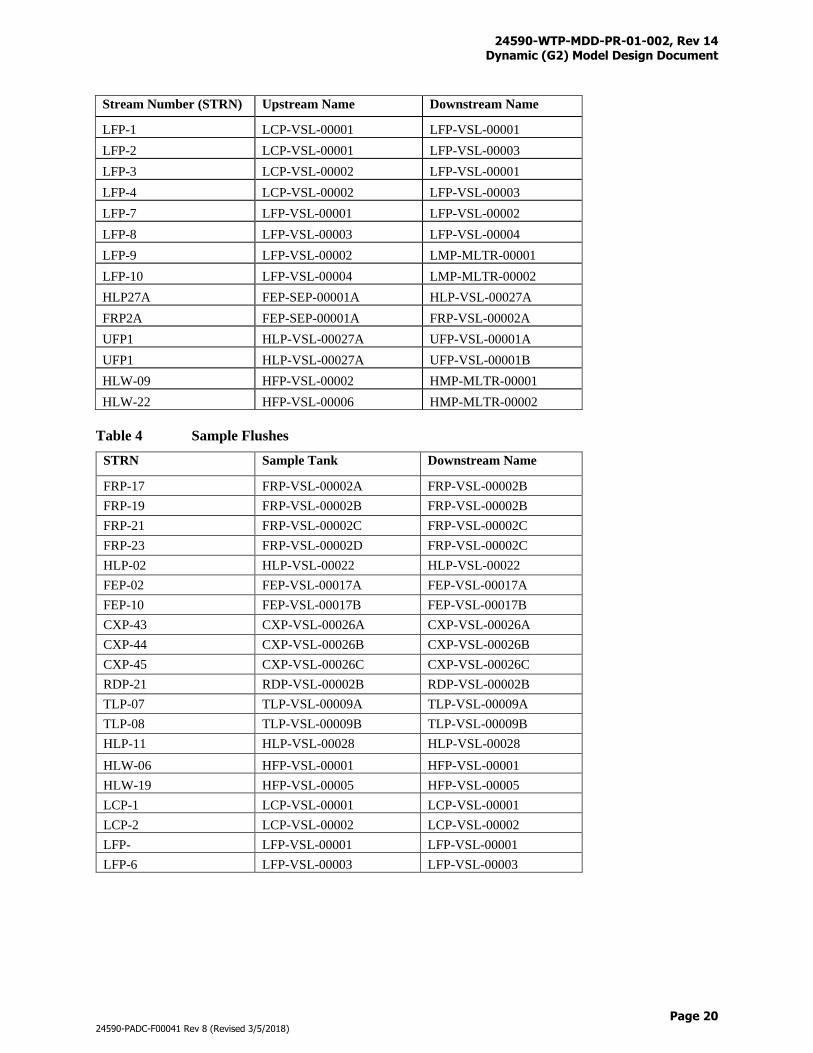
24590-WTP-MDD-PR-01-002, Rev 14 Dynamic (G2) Model Design Document
Page 20
24590-PADC-F00041 Rev 8 (Revised 3/5/2018)
Stream Number (STRN) Upstream Name Downstream Name
LFP-1 LCP-VSL-00001 LFP-VSL-00001
LFP-2 LCP-VSL-00001 LFP-VSL-00003
LFP-3 LCP-VSL-00002 LFP-VSL-00001
LFP-4 LCP-VSL-00002 LFP-VSL-00003
LFP-7 LFP-VSL-00001 LFP-VSL-00002
LFP-8 LFP-VSL-00003 LFP-VSL-00004
LFP-9 LFP-VSL-00002 LMP-MLTR-00001
LFP-10 LFP-VSL-00004 LMP-MLTR-00002
HLP27A FEP-SEP-00001A HLP-VSL-00027A
FRP2A FEP-SEP-00001A FRP-VSL-00002A
UFP1 HLP-VSL-00027A UFP-VSL-00001A
UFP1 HLP-VSL-00027A UFP-VSL-00001B
HLW-09 HFP-VSL-00002 HMP-MLTR-00001
HLW-22 HFP-VSL-00006 HMP-MLTR-00002
Table 4 Sample Flushes
STRN Sample Tank Downstream Name
FRP-17 FRP-VSL-00002A FRP-VSL-00002B
FRP-19 FRP-VSL-00002B FRP-VSL-00002B
FRP-21 FRP-VSL-00002C FRP-VSL-00002C
FRP-23 FRP-VSL-00002D FRP-VSL-00002C
HLP-02 HLP-VSL-00022 HLP-VSL-00022
FEP-02 FEP-VSL-00017A FEP-VSL-00017A
FEP-10 FEP-VSL-00017B FEP-VSL-00017B
CXP-43 CXP-VSL-00026A CXP-VSL-00026A
CXP-44 CXP-VSL-00026B CXP-VSL-00026B
CXP-45 CXP-VSL-00026C CXP-VSL-00026C
RDP-21 RDP-VSL-00002B RDP-VSL-00002B
TLP-07 TLP-VSL-00009A TLP-VSL-00009A
TLP-08 TLP-VSL-00009B TLP-VSL-00009B
HLP-11 HLP-VSL-00028 HLP-VSL-00028
HLW-06 HFP-VSL-00001 HFP-VSL-00001
HLW-19 HFP-VSL-00005 HFP-VSL-00005
LCP-1 LCP-VSL-00001 LCP-VSL-00001
LCP-2 LCP-VSL-00002 LCP-VSL-00002
LFP- LFP-VSL-00001 LFP-VSL-00001
LFP-6 LFP-VSL-00003 LFP-VSL-00003
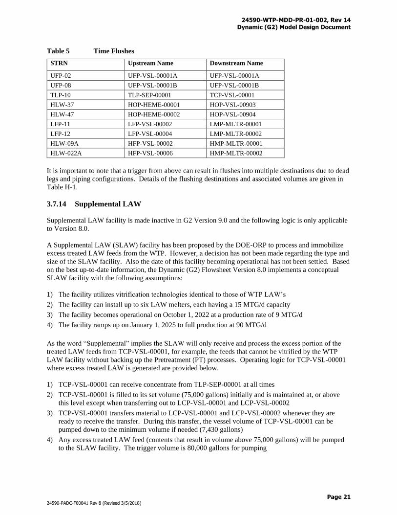
24590-WTP-MDD-PR-01-002, Rev 14 Dynamic (G2) Model Design Document
Page 21
24590-PADC-F00041 Rev 8 (Revised 3/5/2018)
Table 5 Time Flushes
STRN Upstream Name Downstream Name
UFP-02 UFP-VSL-00001A UFP-VSL-00001A
UFP-08 UFP-VSL-00001B UFP-VSL-00001B
TLP-10 TLP-SEP-00001 TCP-VSL-00001
HLW-37 HOP-HEME-00001 HOP-VSL-00903
HLW-47 HOP-HEME-00002 HOP-VSL-00904
LFP-11 LFP-VSL-00002 LMP-MLTR-00001
LFP-12 LFP-VSL-00004 LMP-MLTR-00002
HLW-09A HFP-VSL-00002 HMP-MLTR-00001
HLW-022A HFP-VSL-00006 HMP-MLTR-00002
It is important to note that a trigger from above can result in flushes into multiple destinations due to dead
legs and piping configurations. Details of the flushing destinations and associated volumes are given in
Table H-1.
3.7.14 Supplemental LAW
Supplemental LAW facility is made inactive in G2 Version 9.0 and the following logic is only applicable
to Version 8.0.
A Supplemental LAW (SLAW) facility has been proposed by the DOE-ORP to process and immobilize
excess treated LAW feeds from the WTP. However, a decision has not been made regarding the type and
size of the SLAW facility. Also the date of this facility becoming operational has not been settled. Based
on the best up-to-date information, the Dynamic (G2) Flowsheet Version 8.0 implements a conceptual
SLAW facility with the following assumptions:
1) The facility utilizes vitrification technologies identical to those of WTP LAW’s
2) The facility can install up to six LAW melters, each having a 15 MTG/d capacity
3) The facility becomes operational on October 1, 2022 at a production rate of 9 MTG/d
4) The facility ramps up on January 1, 2025 to full production at 90 MTG/d
As the word “Supplemental” implies the SLAW will only receive and process the excess portion of the
treated LAW feeds from TCP-VSL-00001, for example, the feeds that cannot be vitrified by the WTP
LAW facility without backing up the Pretreatment (PT) processes. Operating logic for TCP-VSL-00001
where excess treated LAW is generated are provided below.
1) TCP-VSL-00001 can receive concentrate from TLP-SEP-00001 at all times
2) TCP-VSL-00001 is filled to its set volume (75,000 gallons) initially and is maintained at, or above
this level except when transferring out to LCP-VSL-00001 and LCP-VSL-00002
3) TCP-VSL-00001 transfers material to LCP-VSL-00001 and LCP-VSL-00002 whenever they are
ready to receive the transfer. During this transfer, the vessel volume of TCP-VSL-00001 can be
pumped down to the minimum volume if needed (7,430 gallons)
4) Any excess treated LAW feed (contents that result in volume above 75,000 gallons) will be pumped
to the SLAW facility. The trigger volume is 80,000 gallons for pumping
24590-WTP-MDD-PR-01-002, Rev 14 Dynamic (G2) Model Design Document
Page 22
24590-PADC-F00041 Rev 8 (Revised 3/5/2018)
Section 3.8.23 provides further details in regard of the conceptual SLAW design.
3.7.15 Vessel Parameters
Vessel parameters, including overflow volume, maximum volume, set volume, and minimum volume,
flowrate, and sample hold time, are listed in Appendix E. Definitions of these vessel parameters are
shown as follows.
1) Overflow volume is the physical limit of a vessel and not modeled in the Dynamic (G2) Flowsheet.
The storage between overflow volume and maximum volume can only be used during off-normal
conditions or under emergency situations
2) Maximum volume is a design volume for normal operations and is equal to the minimum volume plus
the maximum batch volume
3) Set volume is used for the control of pumping operations and situated between the maximum volume
and the minimum volume. A vessel can have an upper set volume, a lower set volume, or both
depending on complexities of the vessel operations. The Dynamic (G2) Flowsheet uses an upper set
point to trigger a discharge and a lower set point to trigger a filling. The storage (headspace) between
the maximum volume and the upper set volume is reserved for unpredictable inflows of other
operations such as line flush and AFA addition. The storage between the lower set volume and the
minimum volume is used to keep the discharge pump running for continuous operations. Multiple set
points can be used for some vessels having more complicated functionalities
4) Minimum (heel) volume is a design volume for normal operations and is determined by the required
net positive suction head (NPSH) of the discharge pump. Vessel contents cannot be pumped to below
this level under normal operations
5) Flowrates is the maximum pump rate of the discharge pump
6) Sample hold time is the time that a vessel must wait before discharging. However, the vessel can still
receive from line flush and AFA operations
3.7.16 Solubility
Significant quantities of oxalate, phosphate, and aluminum are brought in to the WTP for processing.
These solubility-limited constituents exist in the liquid and solid phases in the Tank Farms and are
expected to undergo further phase changes in WTP due to various Pretreatment operations, such as feed
blending, solids concentration, heating, leaching, cooling, solid wash, dilution, pH adjustment, and
evaporation. Phase equilibrium is of paramount importance in determining the fate of these partial
soluble constituents as whether they will be sent to the LAW Facility, Pretreatment recycle streams, or
HLW Facility, which can have major impacts on WTP throughput and waste loading in IHLW.
It is desirable to send more of the solubility-limited constituents to the LAW Facility but the large volume
of wash forward solution required to do this may bog down the CXP system, which in turn extends the
processing duration. Sending wash forward solution at low hydroxide concentration may also cause
aluminum precipitation that clogs ion exchange columns and plugs transfer lines. In contrast, allowing
too much oxalate and phosphate to the Pretreatment recycle streams from wash backward will create a
flywheel effect that reduces the throughput of wastes at ultrafiltration (Note: flywheel effect is the process
phenomenon within the Ultrafiltration Process (UFP) -> Plant Wash and Disposal Process (PWD) ->
Waste Feed Evaporation Process (FEP) -> UFP loop where oxalate and phosphate dissolve in the UFP-
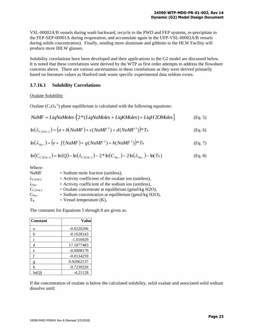
24590-WTP-MDD-PR-01-002, Rev 14 Dynamic (G2) Model Design Document
Page 23
24590-PADC-F00041 Rev 8 (Revised 3/5/2018)
VSL-00002A/B vessels during wash backward, recycle to the PWD and FEP systems, re-precipitate in
the FEP-SEP-00001A during evaporation, and accumulate again in the UFP-VSL-00002A/B vessels
during solids concentration). Finally, sending more aluminate and gibbsite to the HLW Facility will
produce more IHLW glasses.
Solubility correlations have been developed and their applications to the G2 model are discussed below.
It is noted that these correlations were derived by the WTP as first order attempts to address the flowsheet
concerns above. There are various uncertainties in these correlations as they were derived primarily
based on literature values as Hanford tank waste specific experimental data seldom exists.
3.7.16.1 Solubility Correlations
Oxalate Solubility
Oxalate (C2O4-2) phase equilibrium is calculated with the following equations:
OMolesLiqHLiqKMolesLiqNaMolesLiqNaMolesNaMF 2)(*2/ (Eq. 5)
KOC TNaMFdNaMFcNaMFba *)()(ln 32
242 (Eq. 6)
KNa TNaMFhNaMFgNaMFfe *)()(ln 32 (Eq. 7)
)ln(ln2ln*2lnlnln 242242 KNaNaOCOC TCQC (Eq. 8)
Where:
NaMF = Sodium mole fraction (unitless),
C2O4-2 = Activity coefficient of the oxalate ion (unitless),
Na+ = Activity coefficient of the sodium ion (unitless),
CC2O4-2 = Oxalate concentrate at equilibrium (gmol/kg H2O),
CNa+ = Sodium concentration at equilibrium (gmol/kg H2O),
TK = Vessel temperature (K),
The constants for Equations 5 through 8 are given as:
Constant Value
a -0.0220206
b -0.1028143
c -1.016929
d 17.1877483
e -0.0008179
f -0.0134259
g 0.92062137
h -9.7239226
ln(Q) -4.21128
If the concentration of oxalate is below the calculated solubility, solid oxalate and associated solid sodium
dissolve until:
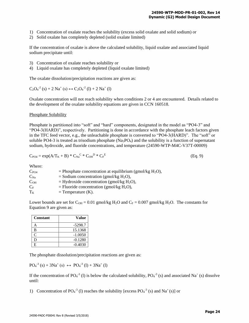
24590-WTP-MDD-PR-01-002, Rev 14 Dynamic (G2) Model Design Document
Page 24
24590-PADC-F00041 Rev 8 (Revised 3/5/2018)
1) Concentration of oxalate reaches the solubility (excess solid oxalate and solid sodium) or
2) Solid oxalate has completely depleted (solid oxalate limited)
If the concentration of oxalate is above the calculated solubility, liquid oxalate and associated liquid
sodium precipitate until:
3) Concentration of oxalate reaches solubility or
4) Liquid oxalate has completely depleted (liquid oxalate limited)
The oxalate dissolution/precipitation reactions are given as:
C2O4-2 (s) + 2 Na+ (s) ↔ C2O4
-2 (l) + 2 Na+ (l)
Oxalate concentration will not reach solubility when conditions 2 or 4 are encountered. Details related to
the development of the oxalate solubility equations are given in CCN 160518.
Phosphate Solubility
Phosphate is partitioned into “soft” and “hard” components, designated in the model as “PO4-3” and
“PO4-3(HARD)”, respectively. Partitioning is done in accordance with the phosphate leach factors given
in the TFC feed vector, e.g., the unleachable phosphate is converted to “PO4-3(HARD)”. The “soft” or
soluble PO4-3 is treated as trisodium phosphate (Na3PO4) and the solubility is a function of supernatant
sodium, hydroxide, and fluoride concentrations, and temperature (24590-WTP-M4C-V37T-00009)
CPO4 = exp(A/TK + B) * CNaC * COH
D * CFE (Eq. 9)
Where:
CPO4 = Phosphate concentration at equilibrium (gmol/kg H2O),
CNa = Sodium concentration (gmol/kg H2O),
COH = Hydroxide concentration (gmol/kg H2O),
CF = Fluoride concentration (gmol/kg H2O),
TK = Temperature (K).
Lower bounds are set for COH = 0.01 gmol/kg H2O and CF = 0.007 gmol/kg H2O. The constants for
Equation 9 are given as:
Constant Value
A -5298.7
B 15.1368
C -1.0050
D -0.1280
E -0.4030
The phosphate dissolution/precipitation reactions are given as:
PO4-3 (s) + 3Na+ (s) ↔ PO4
-3 (l) + 3Na+ (l)
If the concentration of PO4-3 (l) is below the calculated solubility, PO4
-3 (s) and associated Na+ (s) dissolve
until:
1) Concentration of PO4-3 (l) reaches the solubility [excess PO4
-3 (s) and Na+ (s)] or
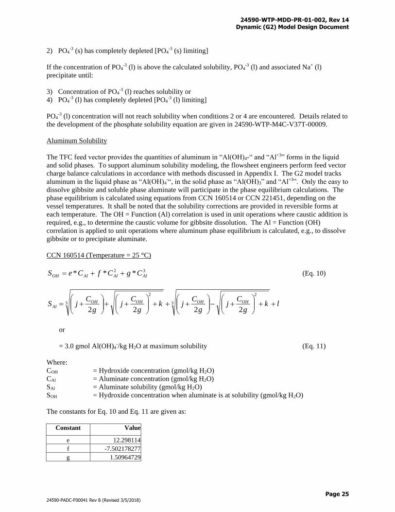
24590-WTP-MDD-PR-01-002, Rev 14 Dynamic (G2) Model Design Document
Page 25
24590-PADC-F00041 Rev 8 (Revised 3/5/2018)
2) PO4-3 (s) has completely depleted [PO4
-3 (s) limiting]
If the concentration of PO4-3 (l) is above the calculated solubility, PO4
-3 (l) and associated Na+ (l)
precipitate until:
3) Concentration of PO4-3 (l) reaches solubility or
4) PO4-3 (l) has completely depleted [PO4
-3 (l) limiting]
PO4-3 (l) concentration will not reach solubility when conditions 2 or 4 are encountered. Details related to
the development of the phosphate solubility equation are given in 24590-WTP-M4C-V37T-00009.
Aluminum Solubility
The TFC feed vector provides the quantities of aluminum in “Al(OH)4-“ and “Al+3” forms in the liquid
and solid phases. To support aluminum solubility modeling, the flowsheet engineers perform feed vector
charge balance calculations in accordance with methods discussed in Appendix I. The G2 model tracks
aluminum in the liquid phase as “Al(OH)4-“, in the solid phase as “Al(OH)3” and “Al+3”. Only the easy to
dissolve gibbsite and soluble phase aluminate will participate in the phase equilibrium calculations. The
phase equilibrium is calculated using equations from CCN 160514 or CCN 221451, depending on the
vessel temperatures. It shall be noted that the solubility corrections are provided in reversible forms at
each temperature. The OH = Function (Al) correlation is used in unit operations where caustic addition is
required, e.g., to determine the caustic volume for gibbsite dissolution. The Al = Function (OH)
correlation is applied to unit operations where aluminum phase equilibrium is calculated, e.g., to dissolve
gibbsite or to precipitate aluminate.
CCN 160514 (Temperature = 25 °C)
32 *** AlAlAlOH CgCfCeS (Eq. 10)
lkg
Cj
g
Cjk
g
Cj
g
CjS OHOHOHOH
Al
3
2
3
2
2222
or
= 3.0 gmol Al(OH)4-/kg H2O at maximum solubility (Eq. 11)
Where:
COH = Hydroxide concentration (gmol/kg H2O)
CAl = Aluminate concentration (gmol/kg H2O)
SAl = Aluminate solubility (gmol/kg H2O)
SOH = Hydroxide concentration when aluminate is at solubility (gmol/kg H2O)
The constants for Eq. 10 and Eq. 11 are given as:
Constant Value
e 12.298114
f -7.502178277
g 1.50964729
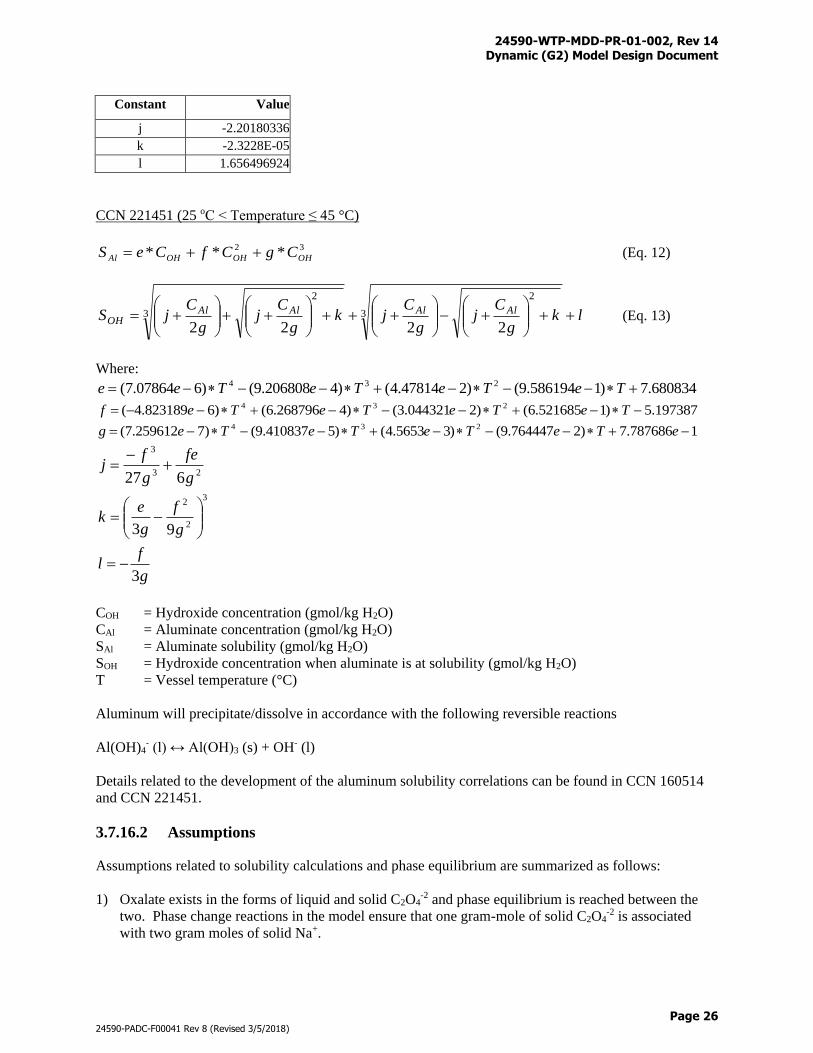
24590-WTP-MDD-PR-01-002, Rev 14 Dynamic (G2) Model Design Document
Page 26
24590-PADC-F00041 Rev 8 (Revised 3/5/2018)
Constant Value
j -2.20180336
k -2.3228E-05
l 1.656496924
CCN 221451 (25 oC < Temperature ≤ 45 °C)
32 *** OHOHOHAl CgCfCeS (Eq. 12)
lkg
Cj
g
Cjk
g
Cj
g
CjS AlAlAlAl
OH
3
2
3
2
2222 (Eq. 13)
Where:
680834.7)1586194.9()247814.4()4206808.9()607864.7( 234 TeTeTeTee
197387.5)1521685.6()2044321.3()4268796.6()6823189.4( 234 TeTeTeTef
1787686.7)2764447.9()35653.4()5410837.9()7259612.7( 234 eTeTeTeTeg
23
3
627 g
fe
g
fj
3
2
2
93
g
f
g
ek
g
fl
3
COH = Hydroxide concentration (gmol/kg H2O)
CAl = Aluminate concentration (gmol/kg H2O)
SAl = Aluminate solubility (gmol/kg H2O)
SOH = Hydroxide concentration when aluminate is at solubility (gmol/kg H2O)
T = Vessel temperature (°C)
Aluminum will precipitate/dissolve in accordance with the following reversible reactions
Al(OH)4- (l) ↔ Al(OH)3 (s) + OH- (l)
Details related to the development of the aluminum solubility correlations can be found in CCN 160514
and CCN 221451.
3.7.16.2 Assumptions
Assumptions related to solubility calculations and phase equilibrium are summarized as follows:
1) Oxalate exists in the forms of liquid and solid C2O4-2 and phase equilibrium is reached between the
two. Phase change reactions in the model ensure that one gram-mole of solid C2O4-2 is associated
with two gram moles of solid Na+.
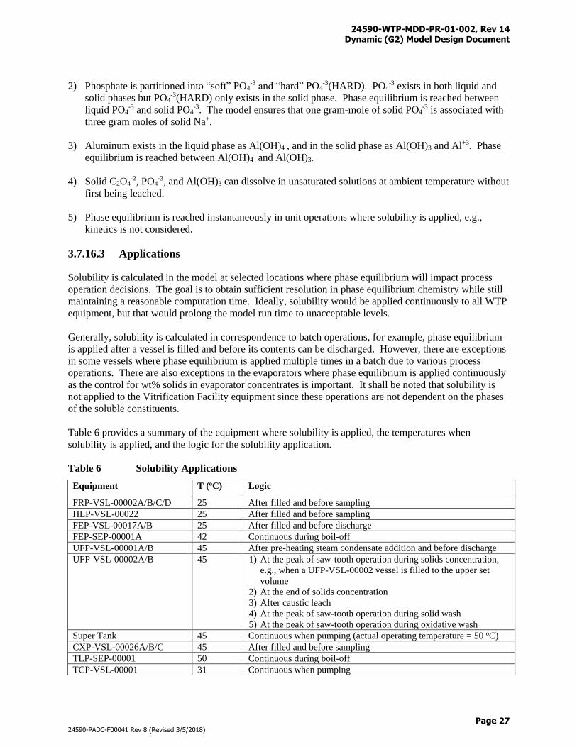
24590-WTP-MDD-PR-01-002, Rev 14 Dynamic (G2) Model Design Document
Page 27
24590-PADC-F00041 Rev 8 (Revised 3/5/2018)
2) Phosphate is partitioned into “soft” PO4-3 and “hard” PO4
-3(HARD). PO4-3 exists in both liquid and
solid phases but PO4-3(HARD) only exists in the solid phase. Phase equilibrium is reached between
liquid PO4-3 and solid PO4
-3. The model ensures that one gram-mole of solid PO4-3 is associated with
three gram moles of solid Na+.
3) Aluminum exists in the liquid phase as Al(OH)4-, and in the solid phase as Al(OH)3 and Al+3. Phase
equilibrium is reached between Al(OH)4- and Al(OH)3.
4) Solid C2O4-2, PO4
-3, and Al(OH)3 can dissolve in unsaturated solutions at ambient temperature without
first being leached.
5) Phase equilibrium is reached instantaneously in unit operations where solubility is applied, e.g.,
kinetics is not considered.
3.7.16.3 Applications
Solubility is calculated in the model at selected locations where phase equilibrium will impact process
operation decisions. The goal is to obtain sufficient resolution in phase equilibrium chemistry while still
maintaining a reasonable computation time. Ideally, solubility would be applied continuously to all WTP
equipment, but that would prolong the model run time to unacceptable levels.
Generally, solubility is calculated in correspondence to batch operations, for example, phase equilibrium
is applied after a vessel is filled and before its contents can be discharged. However, there are exceptions
in some vessels where phase equilibrium is applied multiple times in a batch due to various process
operations. There are also exceptions in the evaporators where phase equilibrium is applied continuously
as the control for wt% solids in evaporator concentrates is important. It shall be noted that solubility is
not applied to the Vitrification Facility equipment since these operations are not dependent on the phases
of the soluble constituents.
Table 6 provides a summary of the equipment where solubility is applied, the temperatures when
solubility is applied, and the logic for the solubility application.
Table 6 Solubility Applications
Equipment T (oC) Logic
FRP-VSL-00002A/B/C/D 25 After filled and before sampling
HLP-VSL-00022 25 After filled and before sampling
FEP-VSL-00017A/B 25 After filled and before discharge
FEP-SEP-00001A 42 Continuous during boil-off
UFP-VSL-00001A/B 45 After pre-heating steam condensate addition and before discharge
UFP-VSL-00002A/B 45 1) At the peak of saw-tooth operation during solids concentration,
e.g., when a UFP-VSL-00002 vessel is filled to the upper set
volume
2) At the end of solids concentration
3) After caustic leach
4) At the peak of saw-tooth operation during solid wash
5) At the peak of saw-tooth operation during oxidative wash
Super Tank 45 Continuous when pumping (actual operating temperature = 50 oC)
CXP-VSL-00026A/B/C 45 After filled and before sampling
TLP-SEP-00001 50 Continuous during boil-off
TCP-VSL-00001 31 Continuous when pumping
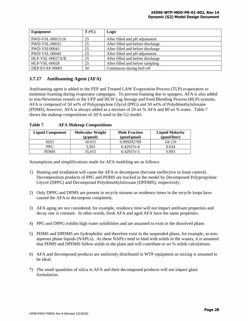
24590-WTP-MDD-PR-01-002, Rev 14 Dynamic (G2) Model Design Document
Page 28
24590-PADC-F00041 Rev 8 (Revised 3/5/2018)
Equipment T (oC) Logic
PWD-VSL-00015/16 25 After filled and pH adjustment
PWD-VSL-00033 25 After filled and before discharge
PWD-VSl-00043 25 After filled and before discharge
PWD-VSL-00044 25 After filled and pH adjustment
HLP-VSL-00027A/B 25 After filled and before discharge
HLP-VSL-00028 25 After filled and before sampling
DEP-EVAP-00001 50 Continuous during boil-off
3.7.17 Antifoaming Agent (AFA)
Antifoaming agent is added to the FEP and Treated LAW Evaporation Process (TLP) evaporators to
minimize foaming during evaporator campaigns. To prevent foaming due to spargers, AFA is also added
to non-Newtonian vessels in the UFP and HLW Lag Storage and Feed Blending Process (HLP) systems.
AFA is composed of 50 wt% of Polypropylene Glycol (PPG) and 50 wt% of Polydimethylsiloxane
(PDMS), however, AFA is always added as a mixture of 20 wt % AFA and 80 wt % water. Table 7
shows the makeup compositions of AFA used in the G2 model.
Table 7 AFA Makeup Compositions
Liquid Component Molecular Weight
(g/gmol)
Mole Fraction
(gmol/gmol)
Liquid Molarity
(gmol/liter)
H2O 18.015 0.999292769 54.119
PPG 3,503 6.42937e-4 0.034
PDMS 35,015 6.42937e-5 0.003
Assumptions and simplifications made for AFA modeling are as follows:
1) Heating and irradiation will cause the AFA to decompose (become ineffective in foam control).
Decomposition products of PPG and PDMS are tracked in the model by Decomposed Polypropylene
Glycol (DPPG) and Decomposed Polydimethylsiloxane (DPDMS), respectively.
2) Only DPPG and DPMS are present in recycle streams as residence times in the recycle loops have
caused the AFA to decompose completely.
3) AFA aging are not considered, for example, residence time will not impact antifoam properties and
decay rate is constant. In other words, fresh AFA and aged AFA have the same properties.
4) PPG and DPPG exhibit high water solubilities and are assumed to exist in the dissolved phase.
5) PDMS and DPDMS are hydrophobic and therefore exist in the suspended phase, for example, as non-
aqueous phase liquids (NAPLs). As these NAPLs tend to bind with solids in the wastes, it is assumed
that PDMS and DPDMS follow solids in the plant and will contribute to wt % solids calculations.
6) AFA and decomposed products are uniformly distributed in WTP equipment as mixing is assumed to
be ideal.
7) The small quantities of silica in AFA and their decomposed products will not impact glass
formulation.
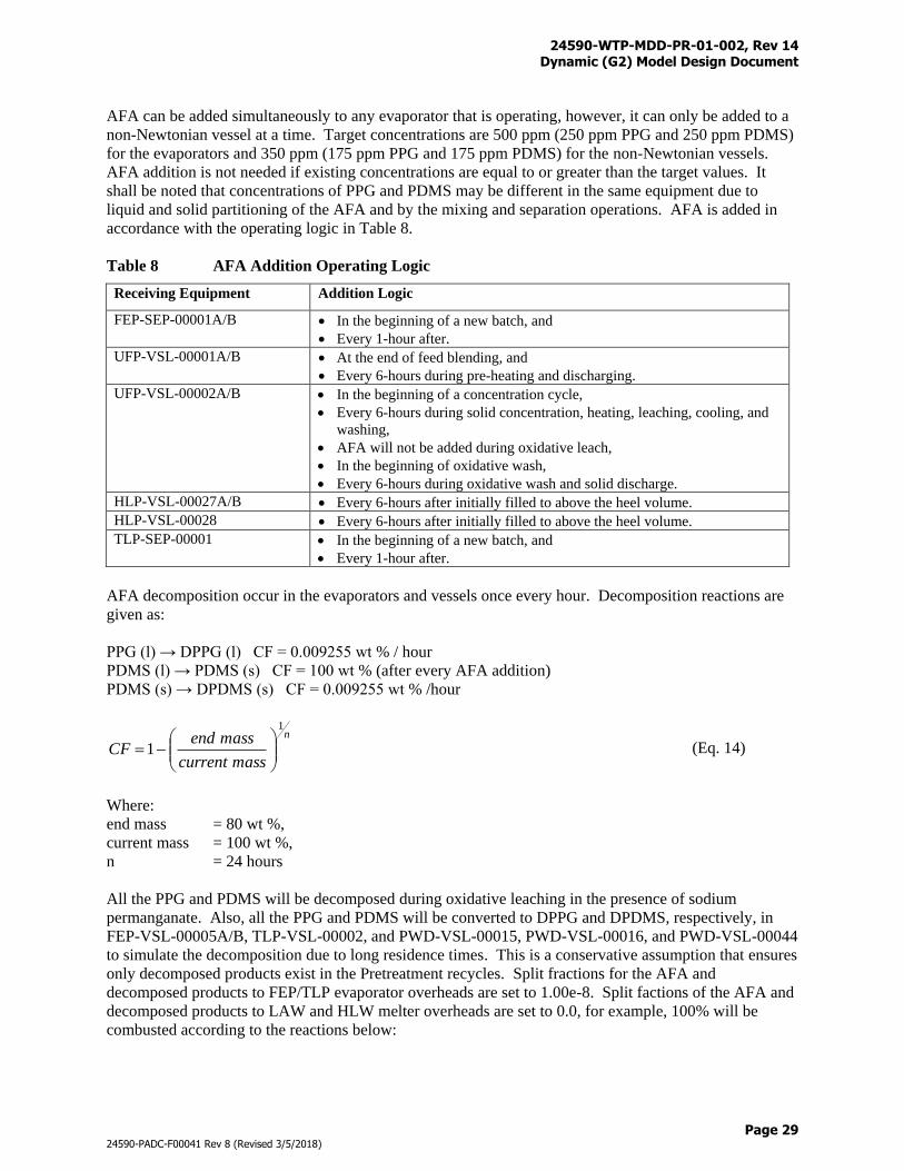
24590-WTP-MDD-PR-01-002, Rev 14 Dynamic (G2) Model Design Document
Page 29
24590-PADC-F00041 Rev 8 (Revised 3/5/2018)
AFA can be added simultaneously to any evaporator that is operating, however, it can only be added to a
non-Newtonian vessel at a time. Target concentrations are 500 ppm (250 ppm PPG and 250 ppm PDMS)
for the evaporators and 350 ppm (175 ppm PPG and 175 ppm PDMS) for the non-Newtonian vessels.
AFA addition is not needed if existing concentrations are equal to or greater than the target values. It
shall be noted that concentrations of PPG and PDMS may be different in the same equipment due to
liquid and solid partitioning of the AFA and by the mixing and separation operations. AFA is added in
accordance with the operating logic in Table 8.
Table 8 AFA Addition Operating Logic
Receiving Equipment Addition Logic
FEP-SEP-00001A/B In the beginning of a new batch, and
Every 1-hour after.
UFP-VSL-00001A/B At the end of feed blending, and
Every 6-hours during pre-heating and discharging.
UFP-VSL-00002A/B In the beginning of a concentration cycle,
Every 6-hours during solid concentration, heating, leaching, cooling, and
washing,
AFA will not be added during oxidative leach,
In the beginning of oxidative wash,
Every 6-hours during oxidative wash and solid discharge.
HLP-VSL-00027A/B Every 6-hours after initially filled to above the heel volume.
HLP-VSL-00028 Every 6-hours after initially filled to above the heel volume.
TLP-SEP-00001 In the beginning of a new batch, and
Every 1-hour after.
AFA decomposition occur in the evaporators and vessels once every hour. Decomposition reactions are
given as:
PPG (l) → DPPG (l) CF = 0.009255 wt % / hour
PDMS (l) → PDMS (s) CF = 100 wt % (after every AFA addition)
PDMS (s) → DPDMS (s) CF = 0.009255 wt % /hour
n
masscurrent
massendCF
1
1
(Eq. 14)
Where:
end mass = 80 wt %,
current mass = 100 wt %,
n = 24 hours
All the PPG and PDMS will be decomposed during oxidative leaching in the presence of sodium
permanganate. Also, all the PPG and PDMS will be converted to DPPG and DPDMS, respectively, in
FEP-VSL-00005A/B, TLP-VSL-00002, and PWD-VSL-00015, PWD-VSL-00016, and PWD-VSL-00044
to simulate the decomposition due to long residence times. This is a conservative assumption that ensures
only decomposed products exist in the Pretreatment recycles. Split fractions for the AFA and
decomposed products to FEP/TLP evaporator overheads are set to 1.00e-8. Split factions of the AFA and
decomposed products to LAW and HLW melter overheads are set to 0.0, for example, 100% will be
combusted according to the reactions below:
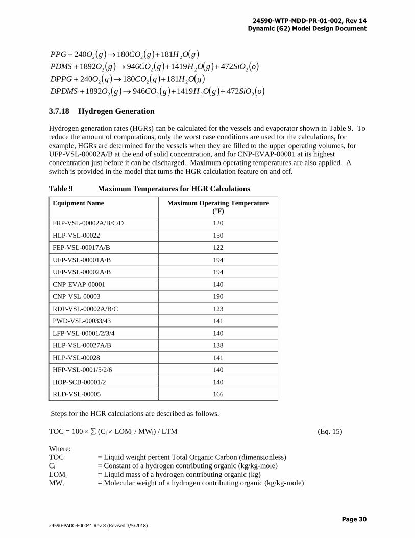
24590-WTP-MDD-PR-01-002, Rev 14 Dynamic (G2) Model Design Document
Page 30
24590-PADC-F00041 Rev 8 (Revised 3/5/2018)
oSiOgOHgCOgODPDMS
gOHgCOgODPPG
oSiOgOHgCOgOPDMS
gOHgCOgOPPG
2222
222
2222
222
47214199461892
181180240
47214199461892
181180240
3.7.18 Hydrogen Generation
Hydrogen generation rates (HGRs) can be calculated for the vessels and evaporator shown in Table 9. To
reduce the amount of computations, only the worst case conditions are used for the calculations, for
example, HGRs are determined for the vessels when they are filled to the upper operating volumes, for
UFP-VSL-00002A/B at the end of solid concentration, and for CNP-EVAP-00001 at its highest
concentration just before it can be discharged. Maximum operating temperatures are also applied. A
switch is provided in the model that turns the HGR calculation feature on and off.
Table 9 Maximum Temperatures for HGR Calculations
Equipment Name Maximum Operating Temperature
(°F)
FRP-VSL-00002A/B/C/D 120
HLP-VSL-00022 150
FEP-VSL-00017A/B 122
UFP-VSL-00001A/B 194
UFP-VSL-00002A/B 194
CNP-EVAP-00001 140
CNP-VSL-00003 190
RDP-VSL-00002A/B/C 123
PWD-VSL-00033/43 141
LFP-VSL-00001/2/3/4 140
HLP-VSL-00027A/B 138
HLP-VSL-00028 141
HFP-VSL-0001/5/2/6 140
HOP-SCB-00001/2 140
RLD-VSL-00005 166
Steps for the HGR calculations are described as follows.
TOC = 100 (Ci LOMi / MWi) / LTM (Eq. 15)
Where:
TOC = Liquid weight percent Total Organic Carbon (dimensionless)
Ci = Constant of a hydrogen contributing organic (kg/kg-mole)
LOMi = Liquid mass of a hydrogen contributing organic (kg)
MWi = Molecular weight of a hydrogen contributing organic (kg/kg-mole)
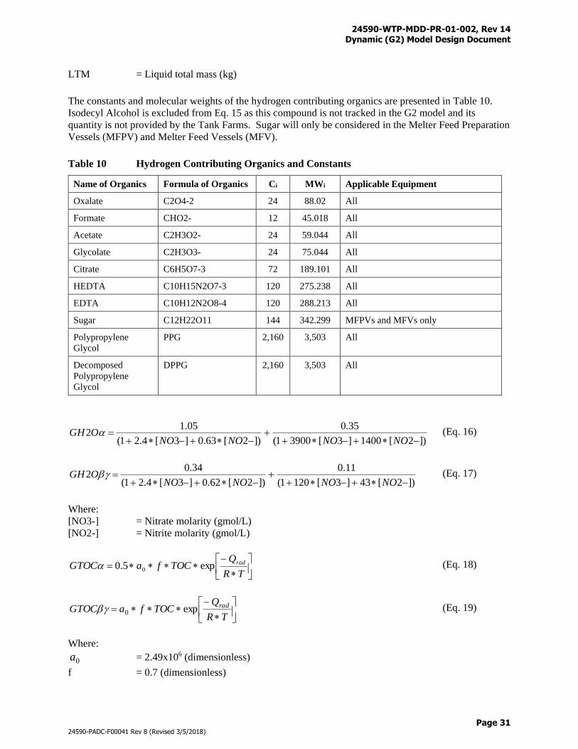
24590-WTP-MDD-PR-01-002, Rev 14 Dynamic (G2) Model Design Document
Page 31
24590-PADC-F00041 Rev 8 (Revised 3/5/2018)
LTM = Liquid total mass (kg)
The constants and molecular weights of the hydrogen contributing organics are presented in Table 10.
Isodecyl Alcohol is excluded from Eq. 15 as this compound is not tracked in the G2 model and its
quantity is not provided by the Tank Farms. Sugar will only be considered in the Melter Feed Preparation
Vessels (MFPV) and Melter Feed Vessels (MFV).
Table 10 Hydrogen Contributing Organics and Constants
Name of Organics Formula of Organics Ci MWi Applicable Equipment
Oxalate C2O4-2 24 88.02 All
Formate CHO2- 12 45.018 All
Acetate C2H3O2- 24 59.044 All
Glycolate C2H3O3- 24 75.044 All
Citrate C6H5O7-3 72 189.101 All
HEDTA C10H15N2O7-3 120 275.238 All
EDTA C10H12N2O8-4 120 288.213 All
Sugar C12H22O11 144 342.299 MFPVs and MFVs only
Polypropylene
Glycol
PPG 2,160 3,503 All
Decomposed
Polypropylene
Glycol
DPPG 2,160 3,503 All
])2[1400]3[39001(
35.0
])2[63.0]3[4.21(
05.12
NONONONOOGH (Eq. 16)
])2[43]3[1201(
11.0
])2[62.0]3[4.21(
34.02
NONONONOOGH (Eq. 17)
Where:
[NO3-] = Nitrate molarity (gmol/L)
[NO2-] = Nitrite molarity (gmol/L)
TR
QTOCfaGTOC radexp5.0 0 (Eq. 18)
TR
QTOCfaGTOC radexp0 (Eq. 19)
Where:
0a = 2.49x10⁶ (dimensionless)
f = 0.7 (dimensionless)
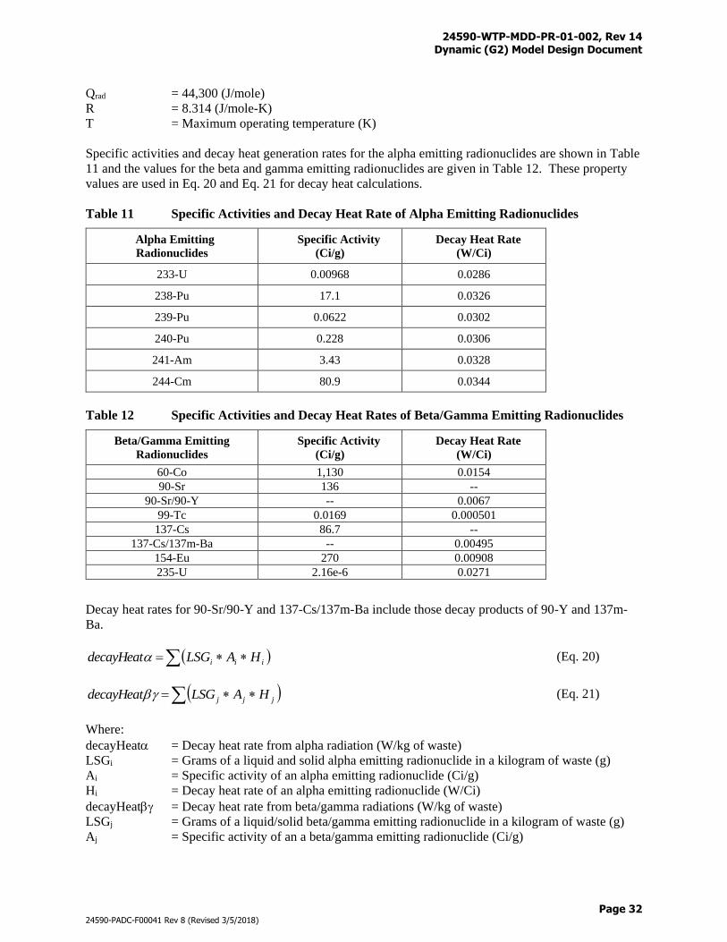
24590-WTP-MDD-PR-01-002, Rev 14 Dynamic (G2) Model Design Document
Page 32
24590-PADC-F00041 Rev 8 (Revised 3/5/2018)
Qrad = 44,300 (J/mole)
R = 8.314 (J/mole-K)
T = Maximum operating temperature (K)
Specific activities and decay heat generation rates for the alpha emitting radionuclides are shown in Table
11 and the values for the beta and gamma emitting radionuclides are given in Table 12. These property
values are used in Eq. 20 and Eq. 21 for decay heat calculations.
Table 11 Specific Activities and Decay Heat Rate of Alpha Emitting Radionuclides
Alpha Emitting
Radionuclides
Specific Activity
(Ci/g)
Decay Heat Rate
(W/Ci)
233-U 0.00968 0.0286
238-Pu 17.1 0.0326
239-Pu 0.0622 0.0302
240-Pu 0.228 0.0306
241-Am 3.43 0.0328
244-Cm 80.9 0.0344
Table 12 Specific Activities and Decay Heat Rates of Beta/Gamma Emitting Radionuclides
Beta/Gamma Emitting
Radionuclides
Specific Activity
(Ci/g)
Decay Heat Rate
(W/Ci)
60-Co 1,130 0.0154
90-Sr 136 --
90-Sr/90-Y -- 0.0067
99-Tc 0.0169 0.000501
137-Cs 86.7 --
137-Cs/137m-Ba -- 0.00495
154-Eu 270 0.00908
235-U 2.16e-6 0.0271
Decay heat rates for 90-Sr/90-Y and 137-Cs/137m-Ba include those decay products of 90-Y and 137m-
Ba.
iii HALSGdecayHeat (Eq. 20)
jjj HALSGdecayHeat (Eq. 21)
Where:
decayHeat = Decay heat rate from alpha radiation (W/kg of waste)
LSGi = Grams of a liquid and solid alpha emitting radionuclide in a kilogram of waste (g)
Ai = Specific activity of an alpha emitting radionuclide (Ci/g)
Hi = Decay heat rate of an alpha emitting radionuclide (W/Ci)
decayHeat = Decay heat rate from beta/gamma radiations (W/kg of waste)
LSGj = Grams of a liquid/solid beta/gamma emitting radionuclide in a kilogram of waste (g)
Aj = Specific activity of an a beta/gamma emitting radionuclide (Ci/g)
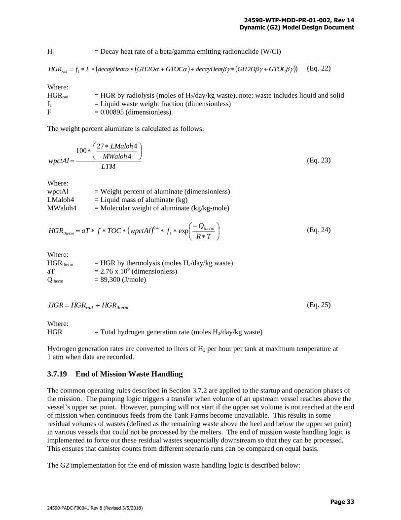
24590-WTP-MDD-PR-01-002, Rev 14 Dynamic (G2) Model Design Document
Page 33
24590-PADC-F00041 Rev 8 (Revised 3/5/2018)
Hj = Decay heat rate of a beta/gamma emitting radionuclide (W/Ci)
GTOCOGHdecayHeatGTOCOGHdecayHeatFfHGRrad 221 (Eq. 22)
Where:
HGRrad = HGR by radiolysis (moles of H2/day/kg waste), note: waste includes liquid and solid
f1 = Liquid waste weight fraction (dimensionless)
F = 0.00895 (dimensionless).
The weight percent aluminate is calculated as follows:
LTM
MWaloh
LMaloh
wpctAl
4
427100
(Eq. 23)
Where:
wpctAl = Weight percent of aluminate (dimensionless)
LMaloh4 = Liquid mass of aluminate (kg)
MWaloh4 = Molecular weight of aluminate (kg/kg-mole)
TR
QfwpctAlTOCfaTHGR therm
therm exp1
4.0 (Eq. 24)
Where:
HGRtherm = HGR by thermolysis (moles H2/day/kg waste)
aT = 2.76 x 10⁹ (dimensionless)
Qtherm = 89,300 (J/mole)
thermrad HGRHGRHGR (Eq. 25)
Where:
HGR = Total hydrogen generation rate (moles H2/day/kg waste)
Hydrogen generation rates are converted to liters of H2 per hour per tank at maximum temperature at
1 atm when data are recorded.
3.7.19 End of Mission Waste Handling
The common operating rules described in Section 3.7.2 are applied to the startup and operation phases of
the mission. The pumping logic triggers a transfer when volume of an upstream vessel reaches above the
vessel’s upper set point. However, pumping will not start if the upper set volume is not reached at the end
of mission when continuous feeds from the Tank Farms become unavailable. This results in some
residual volumes of wastes (defined as the remaining waste above the heel and below the upper set point)
in various vessels that could not be processed by the melters. The end of mission waste handling logic is
implemented to force out these residual wastes sequentially downstream so that they can be processed.
This ensures that canister counts from different scenario runs can be compared on equal basis.
The G2 implementation for the end of mission waste handling logic is described below:
24590-WTP-MDD-PR-01-002, Rev 14 Dynamic (G2) Model Design Document
Page 34
24590-PADC-F00041 Rev 8 (Revised 3/5/2018)
1) The end of mission waste handling logic starts after the last batches of LAW and HLW feeds have
left the Waste Feed Receipt Process (FRP) system and HLP-VSL-00022, respectively
2) WTP line flushes are terminated (because they place waters in already empty vessels)
3) The 24-hour discharge cycle at PVP-SCB-00002 is stopped (because it generates large volume of
recycle)
4) The water flow to PVP-HEME-00001 is discontinued (because it generates large volume of recycle)
5) Wait until the FEP evaporators have processed the original recycles in FEP-VSL-00017A/B, for
example, these vessels are emptied and can be used for new recycles. Note: original recycles are
generated during normal operations and new recycles are generated from residual waste processing
6) Residual wastes are forced out of the HLP-VSL-00022 and FRP vessels until heel volumes are
reached
7) Residual wastes are forced out of UFP-VSL-00001A/B to UFP-VSL-00002A/B where the wastes are
treated according to normal process procedures, such as solids concentration, wash, oxidative leach
and wash, solid discharge, and filter cleaning. UFP2 solid treatments will begin after all the UFP1
residual wastes have been processed and regardless if the solid concentration target (20 wt% solids) is
achieved. Wash water is recycled (new recycles) to PWD
8) Two sub- end of mission processes start simultaneously after the UFP2 vessels are clear of wastes,
one process is to empty the vessels on the path to HLW Melter Process (HMP) and the other is to
clear the vessels on the path to LAW Melter Process (LMP)
9) For the HLW sub-process, wait until HLP-VSL-00028 becomes ready to receive, empty residual
wastes in HLP-VSL-00027A/B
10) Sample and empty residual wastes in HLP-VSL-00028
11) Operate HLW Melter Feed Preparation Vessels as normal regardless if set volume can be achieved
for the last batch
12) Empty HLW MFPVs and MFVs completely, shut down the HMP and HLW Melter Offgas Treatment
Process (HOP) processes. Before HMP and HOP are shut down, new recycles from HOP and HLW
Canister Decontamination Handling (HDH) are routed to PWD through RLD-VSL-00007 according
to normal operation logic
13) For the LAW sub-process, empty the residual wastes from vessels in the following order: Super Tank,
CXP-VSL-00026A/B/C, TCP-VSL-00001, LCP-VSL-00001/2, LFP-VSL-00001/3, and LFP-VSL-
00002/4. Operate the LAW MFPVs as normal regardless if set volume can be achieved for the last
batch
14) Shut down LMP, LAW Melter Offgas Treatment Process (LOP), and LAW Secondary Offgas/Vessel
Process (LVP) processes, and before that new recycles from LOP and LVP are routed to TLP
according to normal operation logic
15) Shut down FEP evaporators and store new recycles in the FEP-VSL-00017A/B vessels to prevent
filling the already emptied UFP vessels. The volumes of new recycles will be recorded
16) Shut down the entire WTP process when both HLW Melter Feed Process (HFP) and LAW Melter
Feed Process (LFP) are clear of wastes
Volumes in the key Pretreatment, LAW Facility, and HLW Facility vessels will be recorded before and
after the end of mission logic is executed. It shall be noted that the end of mission waste handling logic
described above may not represent the actual operations which will be determined by the WTP operations
and maintenance contractor.
24590-WTP-MDD-PR-01-002, Rev 14 Dynamic (G2) Model Design Document
Page 35
24590-PADC-F00041 Rev 8 (Revised 3/5/2018)
3.7.20 Heel Management
NOTICE - THE FOLLOWING HEEL MANAGEMENT OPERATIONS WERE IMPLEMENTED IN
THE DYNAMIC (G2) FLOWSHEET VERSION 7.0 BUT ARE SUSPENDED IN THE DYNAMIC
(G2) FLOWSHEET VERSION 8.0 UPON FINAL RESULTS FROM THE M3 LARGE SCALE
MIXING TESTS.
Heel management operations are performed in selected Pulse Jet Mixer (PJM) vessels to address concerns
of solids accumulation in stationary heels due to inadequate mixing. Two types of heel management
operations can be performed including: a) heel dilution, and b) heel cleanout. Heel dilution is a normal
operation that is performed in Newtonian vessels at regular time intervals, while heel cleanout is an off-
normal operation that is performed in non-Newtonian vessels as needed. For modeling purpose, heel
cleanout is also performed at regular time intervals in G2. Both heel dilution and heel cleanout involve
three steps: a) dilution, b) fluidization, and c) removal. Removal is carried out with a portable pump that
is able to discharge to lower heel levels. The portable pump has a 50 gpm capacity. General rules of the
heel management operations are discussed as follows.
Heel Dilution
1) Continue normal operations until a scheduled date for heel dilution is reached
2) Discharge wastes with the vessel’s fixed pump until the fixed pump heel level is reached
3) Configure jumpers/hoses and install a portable pump in parallel with Steps 1 and 2, preparation time
is not added
4) Continue to discharge wastes until the portable pump heel level is reached
5) Fill vessel to PJM operation level with dilution fluid such as LAW feed from FRP-VSL-
00002A/B/C/D, process condensate, or DI water in priority order
6) Fluidize vessel contents for 1 hour
7) Discharge fluidized contents to portable pump heel level
8) Flush jumpers/hoses with inhibited water
9) Reconfigure jumpers/hoses and uninstall the portable pump, holdup time is not added
Heel Cleanout
1) Continue normal operations until a scheduled date for heel cleanout is reached
2) Discharge wastes with the vessel’s fixed pump until the fixed pump heel level is reached
3) Configure jumpers/hoses and install a portable pump, the preparation process takes 8 hours
4) Continue to discharge wastes until the portable pump heel level is reached
5) Fill vessel to PJM operation level with cleanout fluid, e.g., concentrated solids from upstream
vessel(s) originated from UFP-VSL-00002A/B
6) Fluidize vessel contents for 1 hour
7) Discharge fluidized contents to portable pump heel level
8) Flush jumpers/hoses with inhibited water
9) Reconfigure jumpers/hoses and uninstall the portable pump, the process takes 8 hours
Table 13 provides the specifics for the heel management operations. The logic for triggering the heel
management operations are discussed as appropriate in sub-sections under Section 4.8.
24590-WTP-MDD-PR-01-002, Rev 14 Dynamic (G2) Model Design Document
Page 36
24590-PADC-F00041 Rev 8 (Revised 3/5/2018)
3.7.21 Fate of Mercury
Mercury undergoes complicated transformations in various WTP processes with reduction, oxidation,
vaporization, and condensation reactions (24590-WTP-RPT-PR-01-011). For simplicity, mercury is
tracked as “Hg+2” in liquid and solid. A gaseous state mercury “Hg” is also used for material balance in
the offgas systems. Systems that require special treatments for the fate of mercury modeling include the
LMP, LOP, TLP, HMP, HOP, and PWD. Refer to these system sub-sections under Section 3.8 for
details.
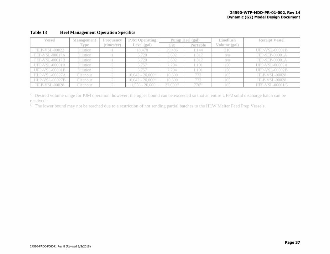
24590-WTP-MDD-PR-01-002, Rev 14 Dynamic (G2) Model Design Document
Page 37
24590-PADC-F00041 Rev 8 (Revised 3/5/2018)
Table 13 Heel Management Operation Specifics
Vessel Management
Type
Frequency
(times/yr)
PJM Operating
Level (gal)
Pump Heel (gal) Lineflush
Volume (gal)
Receipt Vessel
Fix Portable
HLP-VSL-00022 Dilution 1 18,478 29,486 1,144 210 UFP-VSL-00001B
FEP-VSL-00017A Dilution 1 5,720 5,692 1,817 n/a FEP-SEP-00001A
FEP-VSL-00017B Dilution 1 5,720 5,692 1,817 n/a FEP-SEP-00001A
UFP-VSL-00001A Dilution 2 5,757 7,704 1,191 150 UFP-VSL-00002A
UFP-VSL-00001B Dilution 2 5,757 7,704 1,191 150 UFP-VSL-00002B
HLP-VSL-00027A Cleanout 2 10,642 - 20,000a) 10,600 773 165 HLP-VSL-00028
HLP-VSL-00027B Cleanout 2 10,642 - 20,000a) 10,600 773 165 HLP-VSL-00028
HLP-VSL-00028 Cleanout 2 11,556 - 20,000 27,000b) 770b) 165 HFP-VSL-00001/5
a) Desired volume range for PJM operation, however, the upper bound can be exceeded so that an entire UFP2 solid discharge batch can be
received. b) The lower bound may not be reached due to a restriction of not sending partial batches to the HLW Melter Feed Prep Vessels.
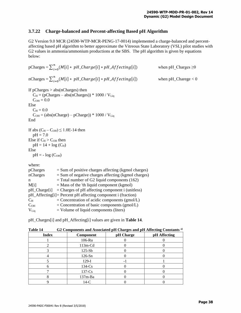
24590-WTP-MDD-PR-01-002, Rev 14 Dynamic (G2) Model Design Document
Page 38
24590-PADC-F00041 Rev 8 (Revised 3/5/2018)
3.7.22 Charge-balanced and Percent-affecting Based pH Algorithm
G2 Version 9.0 MCR (24590-WTP-MCR-PENG-17-0014) implemented a charge-balanced and percent-
affecting based pH algorithm to better approximate the Vitreous State Laboratory (VSL) pilot studies with
G2 values in ammonia/ammonium productions at the SBS. The pH algorithm is given by equations
below:
pCharges =∑ (𝑀[𝑖] ∗ 𝑝𝐻_𝐶ℎ𝑎𝑟𝑔𝑒[𝑖] ∗ 𝑝𝐻_𝐴𝑓𝑓𝑒𝑐𝑡𝑖𝑛𝑔[𝑖])𝑛
𝑖=0 when pH_Charges ≥0
nCharges =∑ (𝑀[𝑖] ∗ 𝑝𝐻_𝐶ℎ𝑎𝑟𝑔𝑒[𝑖] ∗ 𝑝𝐻_𝐴𝑓𝑓𝑒𝑐𝑡𝑖𝑛𝑔[𝑖])𝑛
𝑖=0 when pH_Charege < 0
If pCharges > abs(nCharges) then
CH = (pCharges – abs(nCharges)) * 1000 / VLiq
COH = 0.0
Else
CH = 0.0
COH = (abs(nCharge) – pCharge)) * 1000 / VLiq
End
If abs (CH – COH) ≤ 1.0E-14 then
pH = 7.0
Else if CH > COH then
pH = 14 + log (CH)
Else
pH = - log (COH)
where:
pCharges = Sum of positive charges affecting (kgmol charges)
nCharges = Sum of negative charges affecting (kgmol charges)
n = Total number of G2 liquid components (162)
M[i] = Mass of the ith liquid component (kgmol)
pH_Charge[i] = Charges of pH affecting component i (unitless)
pH_Affecting[i] = Percent pH affecting component i (fraction)
CH = Concentration of acidic components (gmol/L)
COH = Concentration of basic components (gmol/L)
VLiq = Volume of liquid components (liters)
pH_Charges[i] and pH_Affecting[i] values are given in Table 14.
Table 14 G2 Components and Associated pH Charges and pH Affecting Constants a)
Index Component pH Charge pH Affecting
1 106-Ru 0 0
2 113m-Cd 0 0
3 125-Sb 0 0
4 126-Sn 0 0
5 129-I -1 1
6 134-Cs 0 0
7 137-Cs 0 0
8 137m-Ba 0 0
9 14-C 0 0
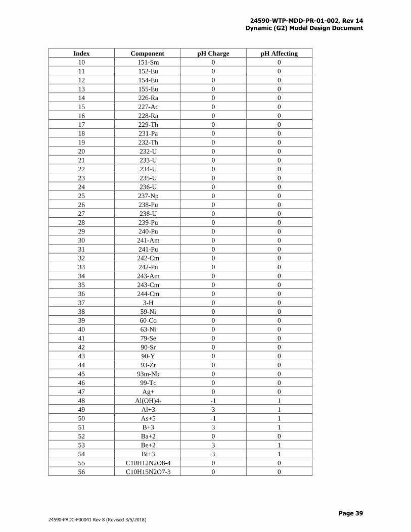
24590-WTP-MDD-PR-01-002, Rev 14 Dynamic (G2) Model Design Document
Page 39
24590-PADC-F00041 Rev 8 (Revised 3/5/2018)
Index Component pH Charge pH Affecting
10 151-Sm 0 0
11 152-Eu 0 0
12 154-Eu 0 0
13 155-Eu 0 0
14 226-Ra 0 0
15 227-Ac 0 0
16 228-Ra 0 0
17 229-Th 0 0
18 231-Pa 0 0
19 232-Th 0 0
20 232-U 0 0
21 233-U 0 0
22 234-U 0 0
23 235-U 0 0
24 236-U 0 0
25 237-Np 0 0
26 238-Pu 0 0
27 238-U 0 0
28 239-Pu 0 0
29 240-Pu 0 0
30 241-Am 0 0
31 241-Pu 0 0
32 242-Cm 0 0
33 242-Pu 0 0
34 243-Am 0 0
35 243-Cm 0 0
36 244-Cm 0 0
37 3-H 0 0
38 59-Ni 0 0
39 60-Co 0 0
40 63-Ni 0 0
41 79-Se 0 0
42 90-Sr 0 0
43 90-Y 0 0
44 93-Zr 0 0
45 93m-Nb 0 0
46 99-Tc 0 0
47 Ag+ 0 0
48 Al(OH)4- -1 1
49 Al+3 3 1
50 As+5 -1 1
51 B+3 3 1
52 Ba+2 0 0
53 Be+2 3 1
54 Bi+3 3 1
55 C10H12N2O8-4 0 0
56 C10H15N2O7-3 0 0
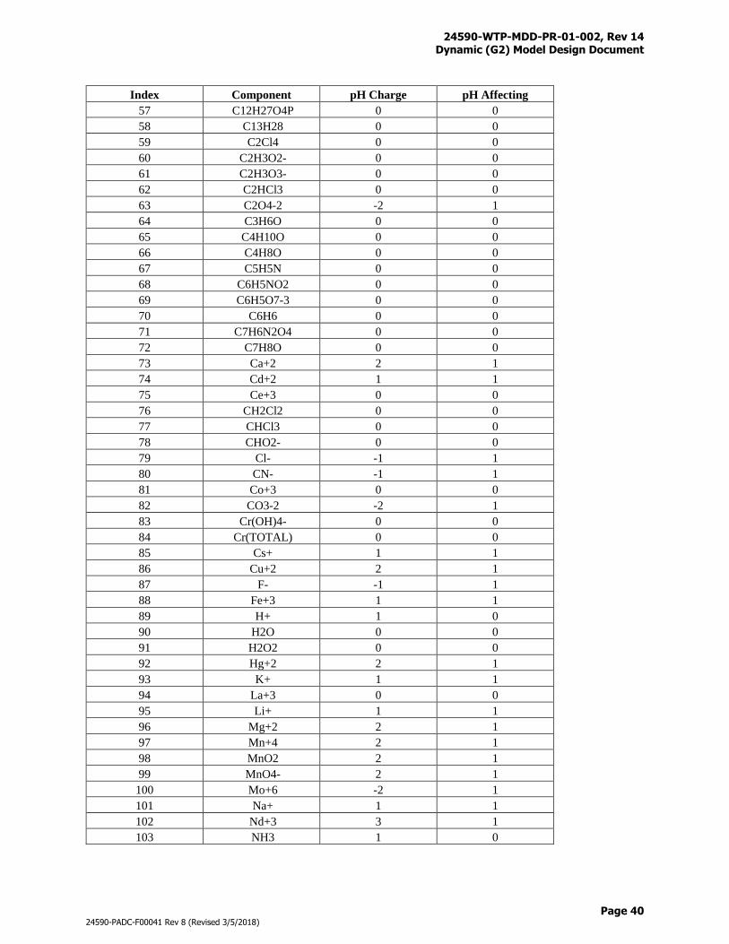
24590-WTP-MDD-PR-01-002, Rev 14 Dynamic (G2) Model Design Document
Page 40
24590-PADC-F00041 Rev 8 (Revised 3/5/2018)
Index Component pH Charge pH Affecting
57 C12H27O4P 0 0
58 C13H28 0 0
59 C2Cl4 0 0
60 C2H3O2- 0 0
61 C2H3O3- 0 0
62 C2HCl3 0 0
63 C2O4-2 -2 1
64 C3H6O 0 0
65 C4H10O 0 0
66 C4H8O 0 0
67 C5H5N 0 0
68 C6H5NO2 0 0
69 C6H5O7-3 0 0
70 C6H6 0 0
71 C7H6N2O4 0 0
72 C7H8O 0 0
73 Ca+2 2 1
74 Cd+2 1 1
75 Ce+3 0 0
76 CH2Cl2 0 0
77 CHCl3 0 0
78 CHO2- 0 0
79 Cl- -1 1
80 CN- -1 1
81 Co+3 0 0
82 CO3-2 -2 1
83 Cr(OH)4- 0 0
84 Cr(TOTAL) 0 0
85 Cs+ 1 1
86 Cu+2 2 1
87 F- -1 1
88 Fe+3 1 1
89 H+ 1 0
90 H2O 0 0
91 H2O2 0 0
92 Hg+2 2 1
93 K+ 1 1
94 La+3 0 0
95 Li+ 1 1
96 Mg+2 2 1
97 Mn+4 2 1
98 MnO2 2 1
99 MnO4- 2 1
100 Mo+6 -2 1
101 Na+ 1 1
102 Nd+3 3 1
103 NH3 1 0
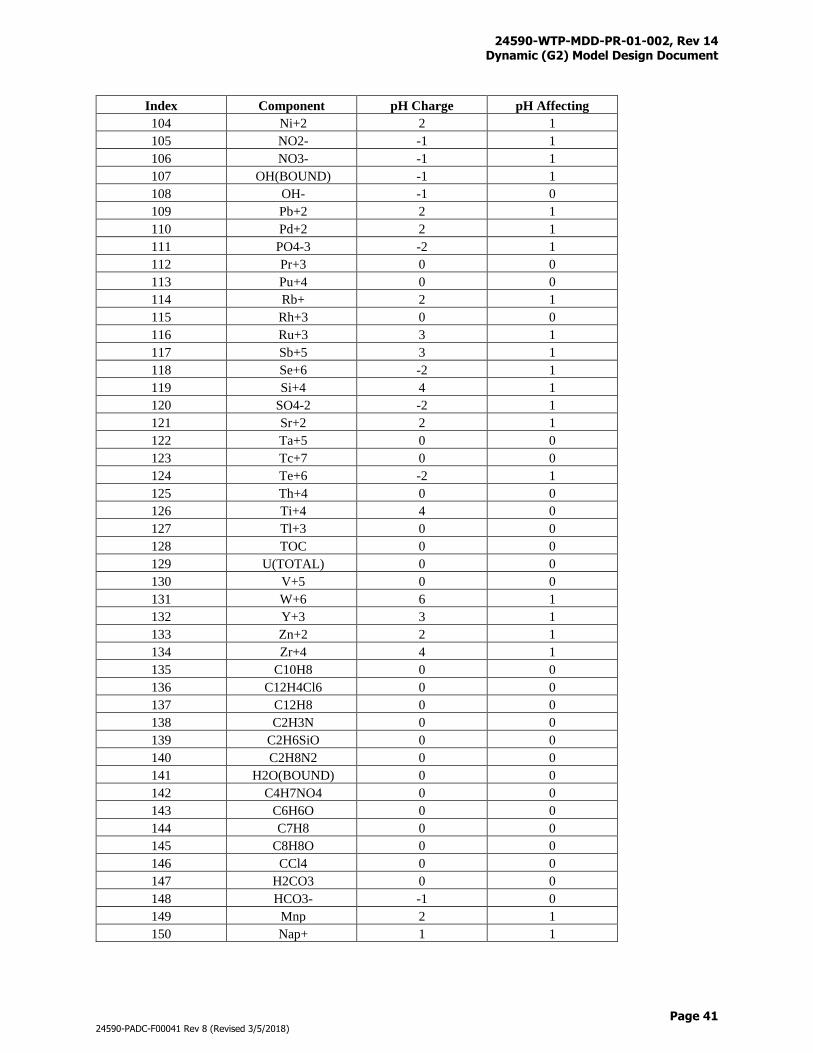
24590-WTP-MDD-PR-01-002, Rev 14 Dynamic (G2) Model Design Document
Page 41
24590-PADC-F00041 Rev 8 (Revised 3/5/2018)
Index Component pH Charge pH Affecting
104 Ni+2 2 1
105 NO2- -1 1
106 NO3- -1 1
107 OH(BOUND) -1 1
108 OH- -1 0
109 Pb+2 2 1
110 Pd+2 2 1
111 PO4-3 -2 1
112 Pr+3 0 0
113 Pu+4 0 0
114 Rb+ 2 1
115 Rh+3 0 0
116 Ru+3 3 1
117 Sb+5 3 1
118 Se+6 -2 1
119 Si+4 4 1
120 SO4-2 -2 1
121 Sr+2 2 1
122 Ta+5 0 0
123 Tc+7 0 0
124 Te+6 -2 1
125 Th+4 0 0
126 Ti+4 4 0
127 Tl+3 0 0
128 TOC 0 0
129 U(TOTAL) 0 0
130 V+5 0 0
131 W+6 6 1
132 Y+3 3 1
133 Zn+2 2 1
134 Zr+4 4 1
135 C10H8 0 0
136 C12H4Cl6 0 0
137 C12H8 0 0
138 C2H3N 0 0
139 C2H6SiO 0 0
140 C2H8N2 0 0
141 H2O(BOUND) 0 0
142 C4H7NO4 0 0
143 C6H6O 0 0
144 C7H8 0 0
145 C8H8O 0 0
146 CCl4 0 0
147 H2CO3 0 0
148 HCO3- -1 0
149 Mnp 2 1
150 Nap+ 1 1
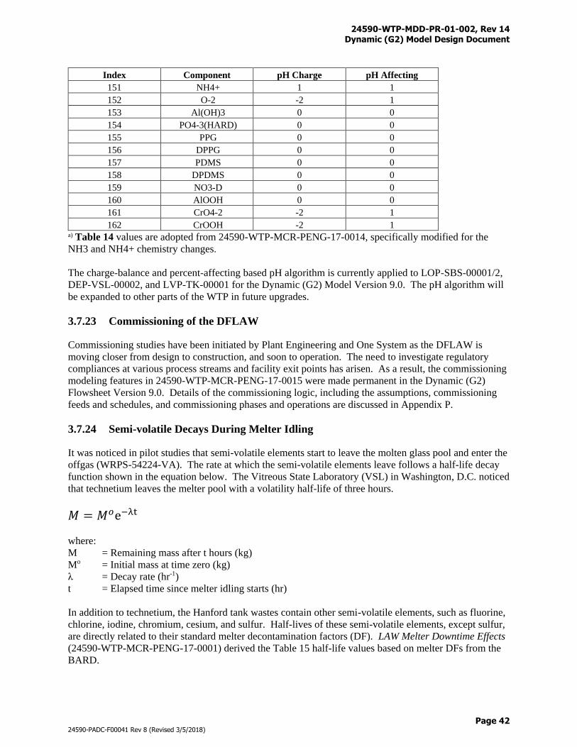
24590-WTP-MDD-PR-01-002, Rev 14 Dynamic (G2) Model Design Document
Page 42
24590-PADC-F00041 Rev 8 (Revised 3/5/2018)
Index Component pH Charge pH Affecting
151 NH4+ 1 1
152 O-2 -2 1
153 Al(OH)3 0 0
154 PO4-3(HARD) 0 0
155 PPG 0 0
156 DPPG 0 0
157 PDMS 0 0
158 DPDMS 0 0
159 NO3-D 0 0
160 AlOOH 0 0
161 CrO4-2 -2 1
162 CrOOH -2 1 a) Table 14 values are adopted from 24590-WTP-MCR-PENG-17-0014, specifically modified for the
NH3 and NH4+ chemistry changes.
The charge-balance and percent-affecting based pH algorithm is currently applied to LOP-SBS-00001/2,
DEP-VSL-00002, and LVP-TK-00001 for the Dynamic (G2) Model Version 9.0. The pH algorithm will
be expanded to other parts of the WTP in future upgrades.
3.7.23 Commissioning of the DFLAW
Commissioning studies have been initiated by Plant Engineering and One System as the DFLAW is
moving closer from design to construction, and soon to operation. The need to investigate regulatory
compliances at various process streams and facility exit points has arisen. As a result, the commissioning
modeling features in 24590-WTP-MCR-PENG-17-0015 were made permanent in the Dynamic (G2)
Flowsheet Version 9.0. Details of the commissioning logic, including the assumptions, commissioning
feeds and schedules, and commissioning phases and operations are discussed in Appendix P.
3.7.24 Semi-volatile Decays During Melter Idling
It was noticed in pilot studies that semi-volatile elements start to leave the molten glass pool and enter the
offgas (WRPS-54224-VA). The rate at which the semi-volatile elements leave follows a half-life decay
function shown in the equation below. The Vitreous State Laboratory (VSL) in Washington, D.C. noticed
that technetium leaves the melter pool with a volatility half-life of three hours.
𝑀 = 𝑀𝑜e−λt
where:
M = Remaining mass after t hours (kg)
Mo = Initial mass at time zero (kg)
λ = Decay rate (hr-1)
t = Elapsed time since melter idling starts (hr)
In addition to technetium, the Hanford tank wastes contain other semi-volatile elements, such as fluorine,
chlorine, iodine, chromium, cesium, and sulfur. Half-lives of these semi-volatile elements, except sulfur,
are directly related to their standard melter decontamination factors (DF). LAW Melter Downtime Effects
(24590-WTP-MCR-PENG-17-0001) derived the Table 15 half-life values based on melter DFs from the
BARD.
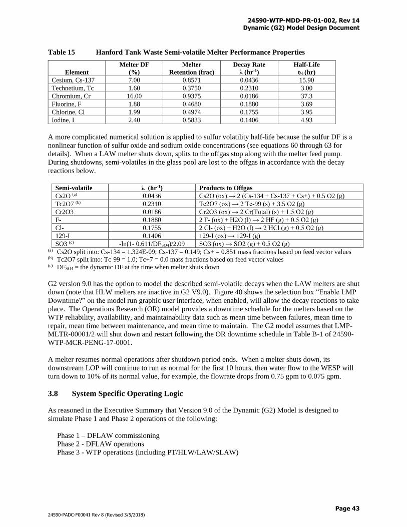
24590-WTP-MDD-PR-01-002, Rev 14 Dynamic (G2) Model Design Document
Page 43
24590-PADC-F00041 Rev 8 (Revised 3/5/2018)
Table 15 Hanford Tank Waste Semi-volatile Melter Performance Properties
Element
Melter DF
(%)
Melter
Retention (frac)
Decay Rate
λ (hr-1)
Half-Life
t½ (hr)
Cesium, Cs-137 7.00 0.8571 0.0436 15.90
Technetium, Tc 1.60 0.3750 0.2310 3.00
Chromium, Cr 16.00 0.9375 0.0186 37.3
Fluorine, F 1.88 0.4680 0.1880 3.69
Chlorine, Cl 1.99 0.4974 0.1755 3.95
Iodine, I 2.40 0.5833 0.1406 4.93
A more complicated numerical solution is applied to sulfur volatility half-life because the sulfur DF is a
nonlinear function of sulfur oxide and sodium oxide concentrations (see equations 60 through 63 for
details). When a LAW melter shuts down, splits to the offgas stop along with the melter feed pump.
During shutdowns, semi-volatiles in the glass pool are lost to the offgas in accordance with the decay
reactions below.
Semi-volatile λ (hr-1) Products to Offgas
Cs2O (a) 0.0436 Cs2O (ox) → 2 (Cs-134 + Cs-137 + Cs+) + 0.5 O2 (g)
Tc2O7 (b) 0.2310 Tc2O7 (ox) → 2 Tc-99 (s) + 3.5 O2 (g)
Cr2O3 0.0186 Cr2O3 (ox) → 2 Cr(Total) (s) + 1.5 O2 (g)
F- 0.1880 2 F- (ox) + H2O (l) → 2 HF (g) + 0.5 O2 (g)
Cl- 0.1755 2 Cl- (ox) + H2O (l) → 2 HCl (g) + 0.5 O2 (g)
129-I 0.1406 129-I (ox) → 129-I (g)
SO3 (c) -ln(1- 0.611/DFSO4)/2.09 SO3 (ox) → SO2 (g) + 0.5 O2 (g) (a) Cs2O split into: Cs-134 = 1.324E-09; Cs-137 = 0.149; Cs+ = 0.851 mass fractions based on feed vector values (b) Tc2O7 split into: Tc-99 = 1.0; Tc+7 = 0.0 mass fractions based on feed vector values (c) DFSO4 = the dynamic DF at the time when melter shuts down
G2 version 9.0 has the option to model the described semi-volatile decays when the LAW melters are shut
down (note that HLW melters are inactive in G2 V9.0). Figure 40 shows the selection box “Enable LMP
Downtime?” on the model run graphic user interface, when enabled, will allow the decay reactions to take
place. The Operations Research (OR) model provides a downtime schedule for the melters based on the
WTP reliability, availability, and maintainability data such as mean time between failures, mean time to
repair, mean time between maintenance, and mean time to maintain. The G2 model assumes that LMP-
MLTR-00001/2 will shut down and restart following the OR downtime schedule in Table B-1 of 24590-
WTP-MCR-PENG-17-0001.
A melter resumes normal operations after shutdown period ends. When a melter shuts down, its
downstream LOP will continue to run as normal for the first 10 hours, then water flow to the WESP will
turn down to 10% of its normal value, for example, the flowrate drops from 0.75 gpm to 0.075 gpm.
3.8 System Specific Operating Logic
As reasoned in the Executive Summary that Version 9.0 of the Dynamic (G2) Model is designed to
simulate Phase 1 and Phase 2 operations of the following:
Phase 1 – DFLAW commissioning
Phase 2 - DFLAW operations
Phase 3 - WTP operations (including PT/HLW/LAW/SLAW)
24590-WTP-MDD-PR-01-002, Rev 14 Dynamic (G2) Model Design Document
Page 44
24590-PADC-F00041 Rev 8 (Revised 3/5/2018)
Systems of the PT, HLW, and SLAW facilities are set inactive for now until an upgrade decision is made
upon DOE-ORP’s approval for the Standard High Solids Vessel (SHSV) design. Operating logic of the
PT/HLW/SLAW systems are kept in this document for information only, for example, they represent the
G2 Version 8.0 logic and are subject to potential changes. For readers who are interested in the potential
design changes, refer to SHSV Concept Design – G2 Flowsheet Run Results (24590-WTP-MRR-PENG-
17-001).
The following sections provide a system-by-system description of the operating logic used in the
Dynamic (G2) Model. Graphical representations of the systems are found in Appendix F and can be used
in conjunction with the reading for a better understanding of the model layout. All reactions provided in
the descriptions occur in the order in which they are presented.
It is noted that Version 8.0 of the Dynamic (G2) Model is configured to perform: a) the baseline UFP2
leaching with gibbsite, or b) the optional UFP2 leaching with boehmite, or c) the optional UFP1 leaching
with gibbsite flowsheet operations. The optional UFP2 leaching with boehmite flowsheet differs from the
baseline flowsheet in how caustic leach reactions are performed, the optional UFP1 leaching flowsheet
differs from the baseline flowsheet primarily in vessels where caustic leach reactions are performed, but
also in feed blending, recycle handling, and solid processes. These three leaching flowsheet options can
be further combined with: d) an infinite SLAW, or e) a single melter SLAW with total capacity up to 90
MTG/d in 15 MTG/d increment, or f) a detailed SLAW with up to six LAW melter trains each having 15
MTG/d capacity. Operating logic and parameters applicable to the optional flowsheets are discussed in
Appendices L and M.
Note: an inactive system in this document means that it has been disabled in G2 Version 9.0, but it is
functional in G2 Version 8.0.
3.8.1 Waste Feed Receipt Process (FRP) System (Inactive)
Vessel Tag # Equipment Description
FRP-VSL-00002A Waste Feed Receipt Vessel
FRP-VSL-00002B Waste Feed Receipt Vessel
FRP-VSL-00002C Waste Feed Receipt Vessel
FRP-VSL-00002D Waste Feed Receipt Vessel
The Waste Feed Receipt Vessels receive batch transfers of LAW feed and associated pre-transfer and
post-transfer line flushes of inhibited water from the Tank Farm. These vessels also receive line flush
water from various operations shown in Table H-1. In general, the transfer lines are flushed after each
use and the flush water goes to not only the pumping and receiving vessels, but also other FRP and FEP
vessels as the result of piping configurations. Headspace, which is defined as the remaining usable
volume after the vessel is filled with slurry wastes, is reserved in each vessel for the line flush water. No
pumps can fill the vessels to above their maximum volumes.
LAW batches from the Tank Farm greater than 1 million gallons are commonly seen. Also, LAW feeds
are generally high in sodium concentration and low in wt % solids. Several rules that control the
acceptance of batches into the plant exist in this system. The rules are narrated as follows:
1) All Tank Farm batches, including LAW and HLW wastes, are limited to solid concentrations less
than or equal to 10 wt% solids
2) At least three of the four Waste Feed Receipt Vessels must be empty before a new LAW batch can be
received. This ensures that FRP is able to receive 1 million gallons of LAW feed, per the WTP
contract requirement
24590-WTP-MDD-PR-01-002, Rev 14 Dynamic (G2) Model Design Document
Page 45
24590-PADC-F00041 Rev 8 (Revised 3/5/2018)
3) Batches must be delivered sequentially, for example, LAW and HLW batches are delivered strictly in
order based on the feed sequence in the feed vector
4) The first LAW batch cannot be received until the model reaches the initial LAW delivery date. The
initial LAW delivery date can be changed based on the desired scenario
5) The first HLW batch cannot be received until the model reaches the initial HLW delivery date. The
initial HLW delivery date can be changed based on the desired scenario
A vessel receives feed until the tank has reached its set volume or the full batch has been received from
the Tank Farm. Separate batches will not mix in the same vessel except for the residual material
remaining in the heel.
Oxalate, phosphate, and aluminum solubility are applied at 25 oC after the transfer is complete. Then the
vessel is sampled and held for the prescribed hold time. When the hold time has expired, the vessel
becomes available to be emptied to UFP. (Disabled flowsheet features pending on M3 results - Besides
normal waste processing, LAW feeds from the FRP vessels are also used for heel dilution operations as
discussed in Section 4.7.20.) It is assumed that vessel contents have cooled down to 25 oC after transfer
from the Tank Farm, held for sampling, and waiting to be discharged. Due to the large size of LAW
batches, some wastes may be stored in the FRP vessels for weeks before they can be processed. Vessels
will be pumped in the order in which they receive waste. Once a Waste Feed Receipt Vessel has reached
its minimum volume, the vessel makes itself available to receive another batch. Once three of the four
Waste Feed Receipt Vessels are empty, another batch is delivered from the Tank Farm.
Figure F-3 provides a graphical illustration of the FRP system where connections with upstream and
downstream systems are shown. Table N-1 provides the totalizer files that are used to track the process
streams and material flows into and out of the FRP.
3.8.2 Waste Feed Evaporation Process (FEP) System (Inactive)
Vessel Tag # Equipment Description
FEP-VSL-00017A Waste Feed Evaporator Feed Vessel
FEP-VSL-00017B Waste Feed Evaporator Feed Vessel
The Waste Feed Evaporator Feed Vessels can receive feeds from the following vessels:
Vessel Tag # Equipment Description
FRP-VSL-00002A Waste Feed Receipt Vessel (heel dilution)
FRP-VSL-00002B Waste Feed Receipt Vessel (heel dilution)
FRP-VSL-00002C Waste Feed Receipt Vessel (heel dilution)
FRP-VSL-00002D Waste Feed Receipt Vessel (heel dilution)
PWD-VSL-00015 Acidic/Alkaline Effluent Vessel
PWD-VSL-00016 Acidic/Alkaline Effluent Vessel
PWD-VSL-00044 Plant Wash Vessel
RDP-VSL-00002B Spent Resin Slurry Vessel
FEP-VSL-00017A and FEP-VSL-00017B operate in an alternating order and receive feeds from one of
the vessels listed above in a first come, first serve fashion. A vessel receives feed until the tank has
reached its set volume which may require multiple transfers from the upstream sources. Headspace is
reserved as the vessel continues to receive line flush water (see Table H-1 for details of various sources of
flushing). Solubility is applied at 25 °C after the vessel is filled. The FEP-VSL-00017A/B vessels are
restricted not to receive wastes with solids concentration greater than 2 wt%. Flags will be raised if the
24590-WTP-MDD-PR-01-002, Rev 14 Dynamic (G2) Model Design Document
Page 46
24590-PADC-F00041 Rev 8 (Revised 3/5/2018)
wt% solids of the upstream wastes exceed the target value. The contents of the vessels are pumped to
FEP-SEP-00001A or FEP-SEP-00001B as appropriate.
(Disabled flowsheet features pending on M3 results - Once a year, a heel dilution is performed in FEP-
VSL-00017A/B to reduce solids concentration in the heel that may have accumulated. Fluids used for
dilution are LAW feeds from FRP-VSL-00002A/B/C/D, process condensate, or DIW in preferred orders.
The FEP-VSL-00017A/B heel dilution is scheduled to separate with other heel dilution operations in
HLP-VSL-00022 and UFP-VSL-00001A/B. The portable pump connects FEP-VSL-00017A/B with
FEP-SEP-00001A. Refer to Section 4.7.20 for further details on general rules of heel dilution and FEP-
VSL-00017A/B specific volume parameters.)
Vessel Tag # Equipment Description
FEP-SEP-00001A Waste Feed Evaporator
FEP-SEP-00001B Waste Feed Evaporator
The Waste Feed Evaporator reboiler and separator vessel are modeled as one unit, for example, their
volumes are combined. Evaporator volume is maintained at a constant level (set-volume) when
operating. Concentrate will initially accumulate then get discharged as the volume rises above the set-
volume. The evaporators receive feeds from FEP-VSL-00017A and FEP-VSL-00017B and associated
line flush water. FEP-SEP-00001A is dedicated for processing recycles while FEP-SEP-00001B is used
for processing the waste feeds through FEP. The FEP-SEP-00001B evaporator train is inactive in the
baseline version of the model owing to the flowsheet design of waste feed bypassing FEP. Processing
rates of the evaporators are limited by a boil-off rate of 30 gallons per minute (gpm), with 2 gpm used for
the evaporator recycle spray resulting in a modeled boil-off rate of 28 gpm. The main purpose of the
evaporator is to reduce volume by concentrating the recycle to a SpG of 1.27 and/or a weight percent
solids of 8.9 %, whichever comes first. Feeds already meeting one or more of these conditions will go
straight through the evaporator without boil-off. The evaporator feed pump and concentrate pump have
maximum capacities at 50 gpm and 34 gpm, respectively. These pump rates are adjusted dynamically at
every time step so that the boil-off rate and the SpG and/or weight percent solids target can be met.
Oxalate and phosphate that come from recycles from the UFP operations tend to precipitate in the
evaporator after boil-off. Solubility is applied continuously at the flash evaporation temperature (42 oC)
which may slightly alter the SpG and/or weight percent solids values of the FEP evaporator bottom
product. Recycle concentrate is routed to a UFP1 vessel in accordance with the current UFP1 operating
conditions as follows:
As soon as a UFP1 vessel finishes its feed blending and pre-heating operations, this vessel becomes a
priority vessel for receiving evaporator bottom products, e.g., it will be used when evaporator starts the
next batch operation regardless of the alternate UFP1 vessel mode.
However, if the evaporator is currently feeding the alternate UFP1 vessel, this batch operation will
continue (e.g., will not stop due to a new UFP1 vessel comes on line) until either: 1) the feeding
FEP17A/B vessel becomes empty, or 2) the receiving alternate UFP1 vessel is full.
Feeding can be switched from the current receiving UFP1 vessel when it gets full to the alternate UFP1
vessel if it still has storage volume available. Evaporator turns idle when both UFP1 vessels are not
available.
To minimize foaming, AFA is added to the evaporator when it starts receiving a new batch from a feed
tank. AFA will be replenished after that in an 1-hour interval to make up losses due to decomposition and
discharge. Target concentrations for PPG and PDMS are discussed in Section 3.7.17.
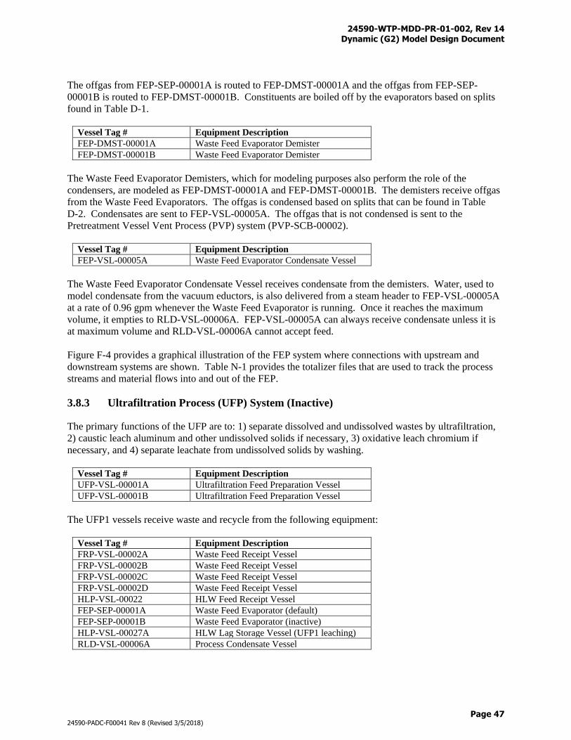
24590-WTP-MDD-PR-01-002, Rev 14 Dynamic (G2) Model Design Document
Page 47
24590-PADC-F00041 Rev 8 (Revised 3/5/2018)
The offgas from FEP-SEP-00001A is routed to FEP-DMST-00001A and the offgas from FEP-SEP-
00001B is routed to FEP-DMST-00001B. Constituents are boiled off by the evaporators based on splits
found in Table D-1.
Vessel Tag # Equipment Description
FEP-DMST-00001A Waste Feed Evaporator Demister
FEP-DMST-00001B Waste Feed Evaporator Demister
The Waste Feed Evaporator Demisters, which for modeling purposes also perform the role of the
condensers, are modeled as FEP-DMST-00001A and FEP-DMST-00001B. The demisters receive offgas
from the Waste Feed Evaporators. The offgas is condensed based on splits that can be found in Table
D-2. Condensates are sent to FEP-VSL-00005A. The offgas that is not condensed is sent to the
Pretreatment Vessel Vent Process (PVP) system (PVP-SCB-00002).
Vessel Tag # Equipment Description
FEP-VSL-00005A Waste Feed Evaporator Condensate Vessel
The Waste Feed Evaporator Condensate Vessel receives condensate from the demisters. Water, used to
model condensate from the vacuum eductors, is also delivered from a steam header to FEP-VSL-00005A
at a rate of 0.96 gpm whenever the Waste Feed Evaporator is running. Once it reaches the maximum
volume, it empties to RLD-VSL-00006A. FEP-VSL-00005A can always receive condensate unless it is
at maximum volume and RLD-VSL-00006A cannot accept feed.
Figure F-4 provides a graphical illustration of the FEP system where connections with upstream and
downstream systems are shown. Table N-1 provides the totalizer files that are used to track the process
streams and material flows into and out of the FEP.
3.8.3 Ultrafiltration Process (UFP) System (Inactive)
The primary functions of the UFP are to: 1) separate dissolved and undissolved wastes by ultrafiltration,
2) caustic leach aluminum and other undissolved solids if necessary, 3) oxidative leach chromium if
necessary, and 4) separate leachate from undissolved solids by washing.
Vessel Tag # Equipment Description
UFP-VSL-00001A Ultrafiltration Feed Preparation Vessel
UFP-VSL-00001B Ultrafiltration Feed Preparation Vessel
The UFP1 vessels receive waste and recycle from the following equipment:
Vessel Tag # Equipment Description
FRP-VSL-00002A Waste Feed Receipt Vessel
FRP-VSL-00002B Waste Feed Receipt Vessel
FRP-VSL-00002C Waste Feed Receipt Vessel
FRP-VSL-00002D Waste Feed Receipt Vessel
HLP-VSL-00022 HLW Feed Receipt Vessel
FEP-SEP-00001A Waste Feed Evaporator (default)
FEP-SEP-00001B Waste Feed Evaporator (inactive)
HLP-VSL-00027A HLW Lag Storage Vessel (UFP1 leaching)
RLD-VSL-00006A Process Condensate Vessel
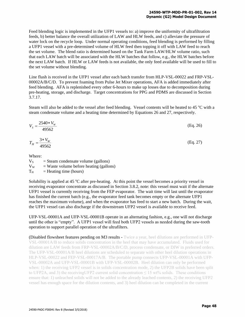
24590-WTP-MDD-PR-01-002, Rev 14 Dynamic (G2) Model Design Document
Page 48
24590-PADC-F00041 Rev 8 (Revised 3/5/2018)
Feed blending logic is implemented in the UFP1 vessels to: a) improve the uniformity of ultrafiltration
feeds, b) better balance the overall utilization of LAW and HLW feeds, and c) alleviate the pressure of
water lock on the recycle loop. Under normal operating conditions, feed blending is performed by filling
a UFP1 vessel with a pre-determined volume of HLW feed then topping it off with LAW feed to reach
the set volume. The blend ratio is determined based on the Tank Farm LAW/HLW volume ratio, such
that each LAW batch will be associated with the HLW batches that follow, e.g., the HLW batches before
the next LAW batch. If HLW or LAW feeds is not available, the only feed available will be used to fill to
the set volume without blending.
Line flush is received in the UFP1 vessel after each batch transfer from HLP-VSL-00022 and FRP-VSL-
00002A/B/C/D. To prevent foaming from Pulse Jet Mixer operations, AFA is added immediately after
feed blending. AFA is replenished every other 6-hours to make up losses due to decomposition during
pre-heating, storage, and discharge. Target concentrations for PPG and PDMS are discussed in Section
3.7.17.
Steam will also be added to the vessel after feed blending. Vessel contents will be heated to 45 oC with a
steam condensate volume and a heating time determined by Equations 26 and 27, respectively.
49562
2540 W
S
VV
(Eq. 26)
49562
3 WH
VT
(Eq. 27)
Where:
VS = Steam condensate volume (gallons)
VW = Waste volume before heating (gallons)
TH = Heating time (hours)
Solubility is applied at 45 oC after pre-heating. At this point the vessel becomes a priority vessel in
receiving evaporator concentrate as discussed in Section 3.8.2, note: this vessel must wait if the alternate
UFP1 vessel is currently receiving from the FEP evaporator. The wait time will last until the evaporator
has finished the current batch (e.g., the evaporator feed tank becomes empty or the alternate UFP1
reaches the maximum volume), and when the evaporator has feed to start a new batch. During the wait,
the UFP1 vessel can also discharge if the downstream UFP2 vessel is available to receive feed.
UFP-VSL-00001A and UFP-VSL-00001B operate in an alternating fashion, e.g., one will not discharge
until the other is “empty”. A UFP1 vessel will feed both UFP2 vessels as needed during the saw-tooth
operation to support parallel operation of the ultrafilters.
(Disabled flowsheet features pending on M3 results - Twice a year, heel dilutions are performed in UFP-
VSL-00001A/B to reduce solids concentration in the heel that may have accumulated. Fluids used for
dilution are LAW feeds from FRP-VSL-00002A/B/C/D, process condensate, or DIW in preferred orders.
The UFP-VSL-00001A/B heel dilutions are scheduled to separate with other heel dilution operations in
HLP-VSL-00022 and FEP-VSL-00017A/B. The portable pump connects UFP-VSL-00001A with UFP-
VSL-00002A and UFP-VSL-00001B with UFP-VSL-00002B. Heel dilution can only be performed
when: 1) the receiving UFP2 vessel is in solids concentration mode, 2) the UFP2B solids have been split
to UFP2A, and 3) the receivingUFP2 current solid concentration ≤ 15 wt% solids. These conditions
ensure that: 1) unleached solids will not be added to the already leached contents, 2) the receiving UFP2
vessel has enough space for the dilution contents, and 3) heel dilution can be completed in the current
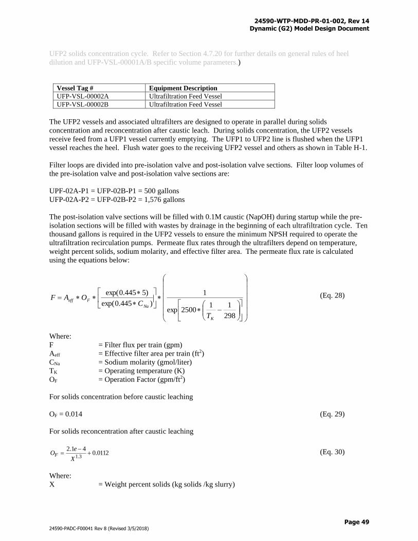
24590-WTP-MDD-PR-01-002, Rev 14 Dynamic (G2) Model Design Document
Page 49
24590-PADC-F00041 Rev 8 (Revised 3/5/2018)
UFP2 solids concentration cycle. Refer to Section 4.7.20 for further details on general rules of heel
dilution and UFP-VSL-00001A/B specific volume parameters.)
Vessel Tag # Equipment Description
UFP-VSL-00002A Ultrafiltration Feed Vessel
UFP-VSL-00002B Ultrafiltration Feed Vessel
The UFP2 vessels and associated ultrafilters are designed to operate in parallel during solids
concentration and reconcentration after caustic leach. During solids concentration, the UFP2 vessels
receive feed from a UFP1 vessel currently emptying. The UFP1 to UFP2 line is flushed when the UFP1
vessel reaches the heel. Flush water goes to the receiving UFP2 vessel and others as shown in Table H-1.
Filter loops are divided into pre-isolation valve and post-isolation valve sections. Filter loop volumes of
the pre-isolation valve and post-isolation valve sections are:
UPF-02A-P1 = UFP-02B-P1 = 500 gallons
UFP-02A-P2 = UFP-02B-P2 = 1,576 gallons
The post-isolation valve sections will be filled with 0.1M caustic (NapOH) during startup while the pre-
isolation sections will be filled with wastes by drainage in the beginning of each ultrafiltration cycle. Ten
thousand gallons is required in the UFP2 vessels to ensure the minimum NPSH required to operate the
ultrafiltration recirculation pumps. Permeate flux rates through the ultrafilters depend on temperature,
weight percent solids, sodium molarity, and effective filter area. The permeate flux rate is calculated
using the equations below:
298
112500exp
1
)445.0exp(
)5445.0exp(
K
Na
Feff
T
COAF (Eq. 28)
Where:
F = Filter flux per train (gpm)
Aeff = Effective filter area per train (ft2)
CNa = Sodium molarity (gmol/liter)
TK = Operating temperature (K)
OF = Operation Factor (gpm/ft2)
For solids concentration before caustic leaching
OF = 0.014 (Eq. 29)
For solids reconcentration after caustic leaching
0112.041.2
3.1
X
eOF (Eq. 30)
Where:
X = Weight percent solids (kg solids /kg slurry)
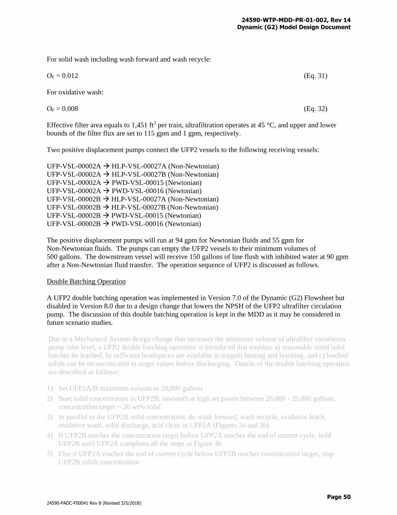
24590-WTP-MDD-PR-01-002, Rev 14 Dynamic (G2) Model Design Document
Page 50
24590-PADC-F00041 Rev 8 (Revised 3/5/2018)
For solid wash including wash forward and wash recycle:
OF = 0.012 (Eq. 31)
For oxidative wash:
OF = 0.008 (Eq. 32)
Effective filter area equals to 1,451 ft2 per train, ultrafiltration operates at 45 °C, and upper and lower
bounds of the filter flux are set to 115 gpm and 1 gpm, respectively.
Two positive displacement pumps connect the UFP2 vessels to the following receiving vessels:
UFP-VSL-00002A HLP-VSL-00027A (Non-Newtonian)
UFP-VSL-00002A HLP-VSL-00027B (Non-Newtonian)
UFP-VSL-00002A PWD-VSL-00015 (Newtonian)
UFP-VSL-00002A PWD-VSL-00016 (Newtonian)
UFP-VSL-00002B HLP-VSL-00027A (Non-Newtonian)
UFP-VSL-00002B HLP-VSL-00027B (Non-Newtonian)
UFP-VSL-00002B PWD-VSL-00015 (Newtonian)
UFP-VSL-00002B PWD-VSL-00016 (Newtonian)
The positive displacement pumps will run at 94 gpm for Newtonian fluids and 55 gpm for
Non-Newtonian fluids. The pumps can empty the UFP2 vessels to their minimum volumes of
500 gallons. The downstream vessel will receive 150 gallons of line flush with inhibited water at 90 gpm
after a Non-Newtonian fluid transfer. The operation sequence of UFP2 is discussed as follows.
Double Batching Operation
A UFP2 double batching operation was implemented in Version 7.0 of the Dynamic (G2) Flowsheet but
disabled in Version 8.0 due to a design change that lowers the NPSH of the UFP2 ultrafilter circulation
pump. The discussion of this double batching operation is kept in the MDD as it may be considered in
future scenario studies.
Due to a Mechanical System design change that increases the minimum volume of ultrafilter circulation
pump inlet level, a UFP2 double batching operation is introduced that enables: a) reasonable sized solid
batches be leached, b) sufficient headspaces are available to support heating and leaching, and c) leached
solids can be reconcentrated to target values before discharging. Details of the double batching operation
are described as follows:
1) Set UFP2A/B maximum volume to 29,900 gallons
2) Start solid concentration in UFP2B, sawtooth at high set points between 26,000 - 25,000 gallons,
concentration target = 20 wt% solid
3) In parallel to the UFP2B solid concentration, do wash forward, wash recycle, oxidative leach,
oxidative wash, solid discharge, acid clean in UFP2A (Figures 3a and 3b)
4) If UFP2B reaches the concentration target before UFP2A reaches the end of current cycle, hold
UFP2B until UFP2A completes all the steps in Figure 3b
5) Else if UFP2A reaches the end of current cycle before UFP2B reaches concentration target, stop
UFP2B solids concentration
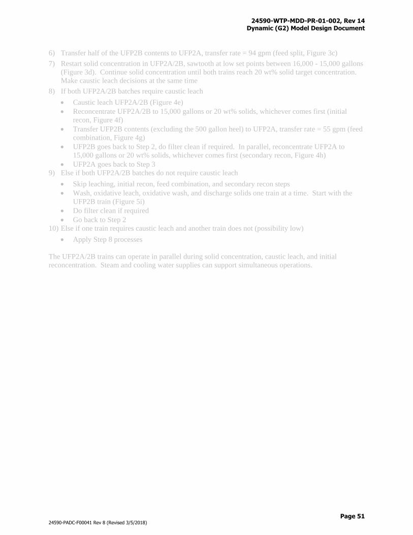
24590-WTP-MDD-PR-01-002, Rev 14 Dynamic (G2) Model Design Document
Page 51
24590-PADC-F00041 Rev 8 (Revised 3/5/2018)
6) Transfer half of the UFP2B contents to UFP2A, transfer rate = 94 gpm (feed split, Figure 3c)
7) Restart solid concentration in UFP2A/2B, sawtooth at low set points between 16,000 - 15,000 gallons
(Figure 3d). Continue solid concentration until both trains reach 20 wt% solid target concentration.
Make caustic leach decisions at the same time
8) If both UFP2A/2B batches require caustic leach
Caustic leach UFP2A/2B (Figure 4e)
Reconcentrate UFP2A/2B to 15,000 gallons or 20 wt% solids, whichever comes first (initial
recon, Figure 4f)
Transfer UFP2B contents (excluding the 500 gallon heel) to UFP2A, transfer rate = 55 gpm (feed
combination, Figure 4g)
UFP2B goes back to Step 2, do filter clean if required. In parallel, reconcentrate UFP2A to
15,000 gallons or 20 wt% solids, whichever comes first (secondary recon, Figure 4h)
UFP2A goes back to Step 3
9) Else if both UFP2A/2B batches do not require caustic leach
Skip leaching, initial recon, feed combination, and secondary recon steps
Wash, oxidative leach, oxidative wash, and discharge solids one train at a time. Start with the
UFP2B train (Figure 5i)
Do filter clean if required
Go back to Step 2
10) Else if one train requires caustic leach and another train does not (possibility low)
Apply Step 8 processes
The UFP2A/2B trains can operate in parallel during solid concentration, caustic leach, and initial
reconcentration. Steam and cooling water supplies can support simultaneous operations.
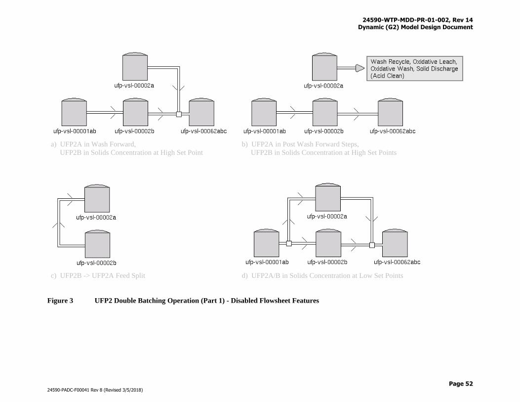
24590-WTP-MDD-PR-01-002, Rev 14 Dynamic (G2) Model Design Document
Page 52
24590-PADC-F00041 Rev 8 (Revised 3/5/2018)
a) UFP2A in Wash Forward,
UFP2B in Solids Concentration at High Set Point
b) UFP2A in Post Wash Forward Steps,
UFP2B in Solids Concentration at High Set Points
c) UFP2B -> UFP2A Feed Split
d) UFP2A/B in Solids Concentration at Low Set Points
Figure 3 UFP2 Double Batching Operation (Part 1) - Disabled Flowsheet Features
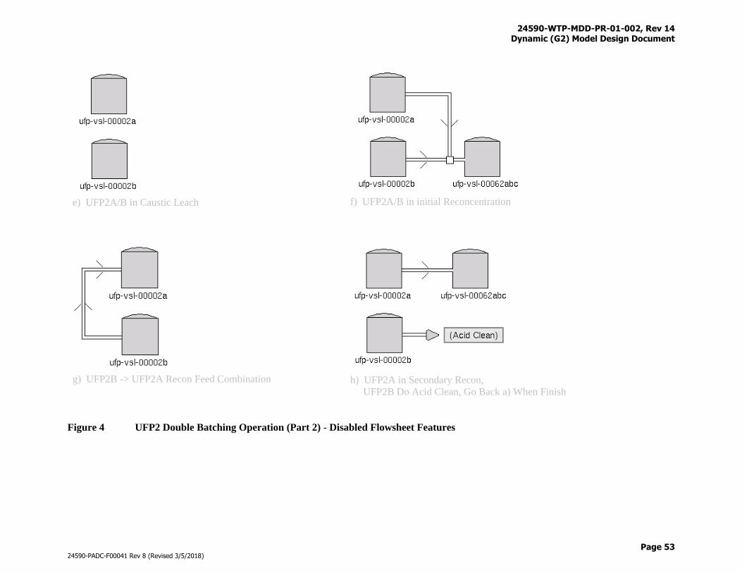
24590-WTP-MDD-PR-01-002, Rev 14 Dynamic (G2) Model Design Document
Page 53
24590-PADC-F00041 Rev 8 (Revised 3/5/2018)
e) UFP2A/B in Caustic Leach
f) UFP2A/B in initial Reconcentration
g) UFP2B -> UFP2A Recon Feed Combination
h) UFP2A in Secondary Recon,
UFP2B Do Acid Clean, Go Back a) When Finish
Figure 4 UFP2 Double Batching Operation (Part 2) - Disabled Flowsheet Features
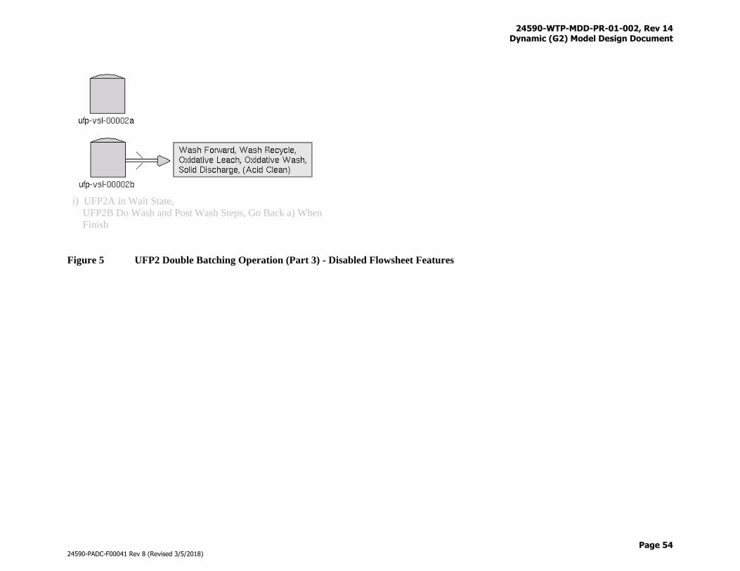
24590-WTP-MDD-PR-01-002, Rev 14 Dynamic (G2) Model Design Document
Page 54
24590-PADC-F00041 Rev 8 (Revised 3/5/2018)
i) UFP2A in Wait State,
UFP2B Do Wash and Post Wash Steps, Go Back a) When
Finish
Figure 5 UFP2 Double Batching Operation (Part 3) - Disabled Flowsheet Features
24590-WTP-MDD-PR-01-002, Rev 14 Dynamic (G2) Model Design Document
Page 55
24590-PADC-F00041 Rev 8 (Revised 3/5/2018)
Solids Concentration
AFA is added immediately after a UFP2 is filled to the set volume with feed from UFP1. Target
concentrations for PPG and PDMS are discussed in Section 3.7.17. Solids concentration begins by
pumping and filling (sawtooths) the UFP2 vessel between the upper set volume (14,500 gallons) and the
lower setpoint (13,500 gallons), the UFP2 vessel is allowed to receive before it reaches the lower setpoint
to ensure an undisrupted ultrafiltration operation. Through the circulation pump, ultrafilter permeate is
routed to the Ultrafiltration Permeate Collection Vessel (UFP-VSL-00062A/B/C) while concentrated
slurry is returned to the UFP2 vessel. The solids concentration process continues until 20 wt % solids has
been reached. Solubility correlations are applied at 45 °C at the peak of the sawtooth during solids
concentration. AFA is replenished every 6-hours to make up losses due to decomposition during the
remaining UFP2 operations except during oxidative leaching.
Caustic Leach
Generally caustic leach can reduce the HLW glass produced as most of the WTP solids are aluminum
limiting. For waste batches that are limited by other Specification 1 species (see bounding condition flags
in Figure 5 for details), caustic leach is unnecessary as it increases processing time and adds sodium to the
waste. A caustic leach decision logic has been developed by flowsheet engineers that determines if a
waste batch is aluminum limiting and consequently if the caustic leach can reduce HLW glass by 10% or
more. Wash factors as well as the subsequent oxidative leach are also considered. Figure 6 through
Figure 9 provide logic diagrams that are implemented in G2 model, where:
EG-Majors is the estimated glass amount expected if the glass limited by major glass constituents
EG-Minors is the estimated glass amount expected if the glass limited by minor glass constituents
EG-Cr is the estimated glass amount expected if the glass is chromium limited
BC-i is the HLW glass oxide limiting value set in G2 as wt fraction units, not wt%
LF values are Tank Farm’s given leach factor values for corresponding element, units in wt-
fraction
PTWF-C2O4 is a wash factor for solid oxalate in Pretreatment
PO4-3(Hard) is the insoluble form of phosphate in the batch, kilo-moles
PO4-3 is the soluble form of phosphate in the batch, kilo-moles
Ppf is an estimated average of the soluble phosphate that will precipitate and report to HLW for
vitrification
OxLF is the oxidative leach factor for chromium
WF-Ox is the estimated wash factor for removing dissolved chromium and other salts from the
batch after oxidative leaching. Presently, three vessel washing are preformed
Details for the development of this caustic leach decisions logic can be found in 24590-WTP-MCR-PET-
09-0048.
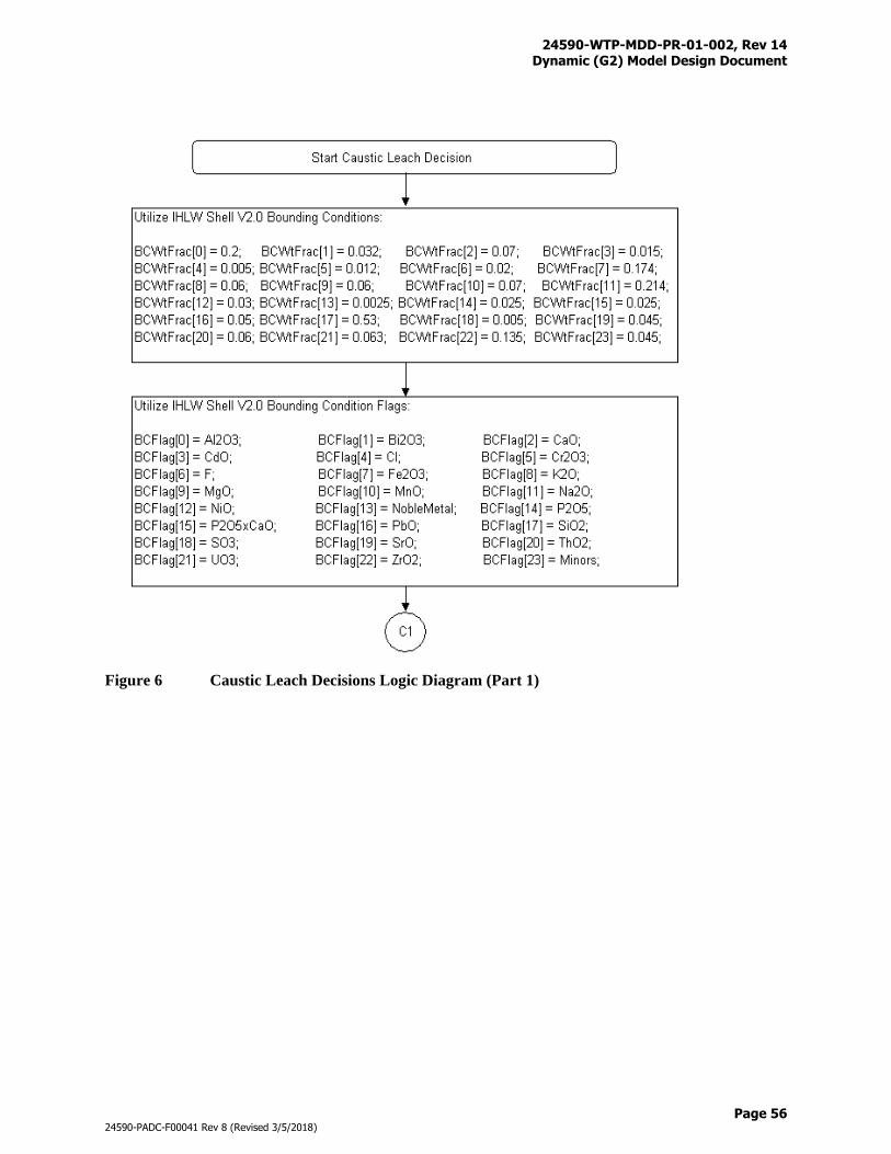
24590-WTP-MDD-PR-01-002, Rev 14 Dynamic (G2) Model Design Document
Page 56
24590-PADC-F00041 Rev 8 (Revised 3/5/2018)
Figure 6 Caustic Leach Decisions Logic Diagram (Part 1)
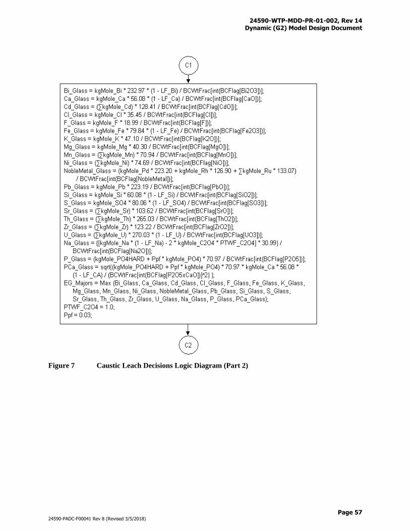
24590-WTP-MDD-PR-01-002, Rev 14 Dynamic (G2) Model Design Document
Page 57
24590-PADC-F00041 Rev 8 (Revised 3/5/2018)
Figure 7 Caustic Leach Decisions Logic Diagram (Part 2)
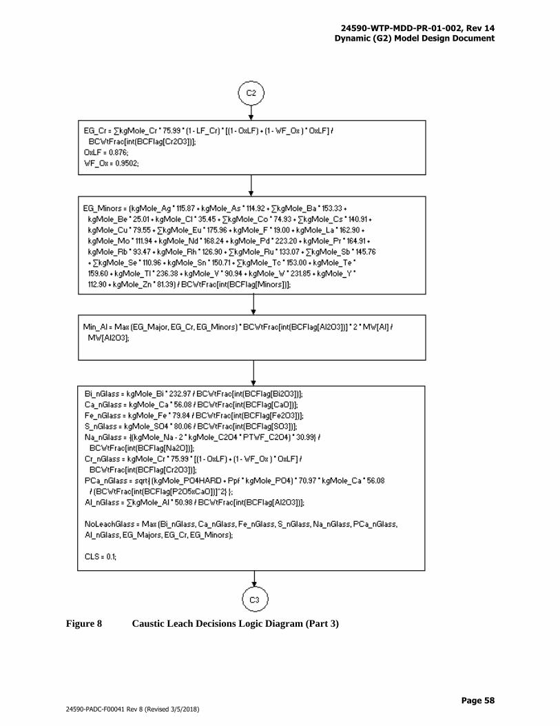
24590-WTP-MDD-PR-01-002, Rev 14 Dynamic (G2) Model Design Document
Page 58
24590-PADC-F00041 Rev 8 (Revised 3/5/2018)
Figure 8 Caustic Leach Decisions Logic Diagram (Part 3)
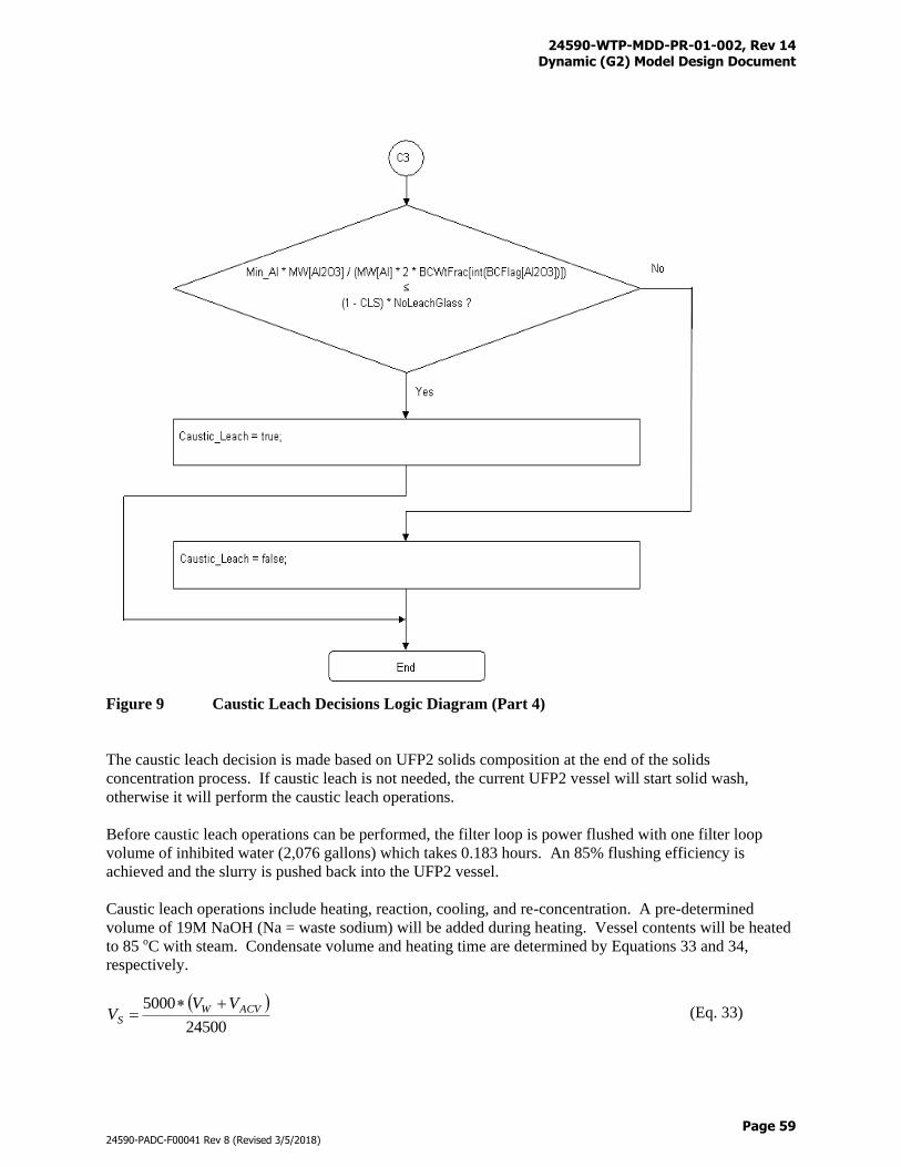
24590-WTP-MDD-PR-01-002, Rev 14 Dynamic (G2) Model Design Document
Page 59
24590-PADC-F00041 Rev 8 (Revised 3/5/2018)
Figure 9 Caustic Leach Decisions Logic Diagram (Part 4)
The caustic leach decision is made based on UFP2 solids composition at the end of the solids
concentration process. If caustic leach is not needed, the current UFP2 vessel will start solid wash,
otherwise it will perform the caustic leach operations.
Before caustic leach operations can be performed, the filter loop is power flushed with one filter loop
volume of inhibited water (2,076 gallons) which takes 0.183 hours. An 85% flushing efficiency is
achieved and the slurry is pushed back into the UFP2 vessel.
Caustic leach operations include heating, reaction, cooling, and re-concentration. A pre-determined
volume of 19M NaOH (Na = waste sodium) will be added during heating. Vessel contents will be heated
to 85 oC with steam. Condensate volume and heating time are determined by Equations 33 and 34,
respectively.
24500
5000 ACVWS
VVV
(Eq. 33)
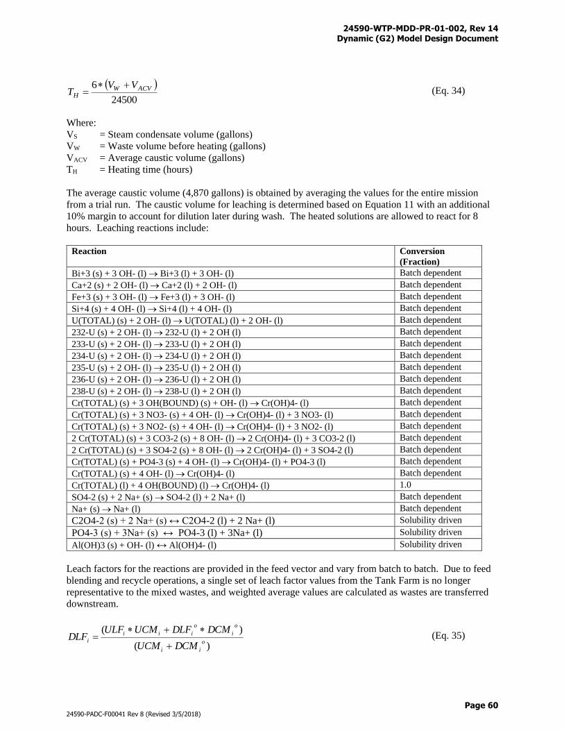
24590-WTP-MDD-PR-01-002, Rev 14 Dynamic (G2) Model Design Document
Page 60
24590-PADC-F00041 Rev 8 (Revised 3/5/2018)
24500
6 ACVWH
VVT
(Eq. 34)
Where:
VS = Steam condensate volume (gallons)
VW = Waste volume before heating (gallons)
VACV = Average caustic volume (gallons)
TH = Heating time (hours)
The average caustic volume (4,870 gallons) is obtained by averaging the values for the entire mission
from a trial run. The caustic volume for leaching is determined based on Equation 11 with an additional
10% margin to account for dilution later during wash. The heated solutions are allowed to react for 8
hours. Leaching reactions include:
Reaction Conversion
(Fraction)
Bi+3 (s) + 3 OH- (l) Bi+3 (l) + 3 OH- (l) Batch dependent
Ca+2 (s) + 2 OH- (l) Ca+2 (l) + 2 OH- (l) Batch dependent
Fe+3 (s) + 3 OH- (l) Fe+3 (l) + 3 OH- (l) Batch dependent
Si+4 (s) + 4 OH- (l) Si+4 (l) + 4 OH- (l) Batch dependent
U(TOTAL) (s) + 2 OH- (l) U(TOTAL) (l) + 2 OH- (l) Batch dependent
232-U (s) + 2 OH- (l) 232-U (l) + 2 OH (l) Batch dependent
233-U (s) + 2 OH- (l) 233-U (l) + 2 OH (l) Batch dependent
234-U (s) + 2 OH- (l) 234-U (l) + 2 OH (l) Batch dependent
235-U (s) + 2 OH- (l) 235-U (l) + 2 OH (l) Batch dependent
236-U (s) + 2 OH- (l) 236-U (l) + 2 OH (l) Batch dependent
238-U (s) + 2 OH- (l) 238-U (l) + 2 OH (l) Batch dependent
Cr(TOTAL) (s) + 3 OH(BOUND) (s) + OH- (l) Cr(OH)4- (l) Batch dependent
Cr(TOTAL) (s) + 3 NO3- (s) + 4 OH- (l) Cr(OH)4- (l) + 3 NO3- (l) Batch dependent
Cr(TOTAL) (s) + 3 NO2- (s) + 4 OH- (l) Cr(OH)4- (l) + 3 NO2- (l) Batch dependent
2 Cr(TOTAL) (s) + 3 CO3-2 (s) + 8 OH- (l) 2 Cr(OH)4- (l) + 3 CO3-2 (l) Batch dependent
2 Cr(TOTAL) (s) + 3 SO4-2 (s) + 8 OH- (l) 2 Cr(OH)4- (l) + 3 SO4-2 (l) Batch dependent
Cr(TOTAL) (s) + PO4-3 (s) + 4 OH- (l) Cr(OH)4- (l) + PO4-3 (l) Batch dependent
Cr(TOTAL) (s) + 4 OH- (l) Cr(OH)4- (l) Batch dependent
Cr(TOTAL) (l) + 4 OH(BOUND) (l) Cr(OH)4- (l) 1.0
SO4-2 (s) + 2 Na+ (s) SO4-2 (l) + 2 Na+ (l) Batch dependent
Na+ (s) Na+ (l) Batch dependent
C2O4-2 (s) + 2 Na+ (s) ↔ C2O4-2 (l) + 2 Na+ (l) Solubility driven
PO4-3 (s) + 3Na+ (s) ↔ PO4-3 (l) + 3Na+ (l) Solubility driven
Al(OH)3 (s) + OH- (l) ↔ Al(OH)4- (l) Solubility driven
Leach factors for the reactions are provided in the feed vector and vary from batch to batch. Due to feed
blending and recycle operations, a single set of leach factor values from the Tank Farm is no longer
representative to the mixed wastes, and weighted average values are calculated as wastes are transferred
downstream.
)(
)(o
ii
o
i
o
iii
iDCMUCM
DCMDLFUCMULFDLF
(Eq. 35)
24590-WTP-MDD-PR-01-002, Rev 14 Dynamic (G2) Model Design Document
Page 61
24590-PADC-F00041 Rev 8 (Revised 3/5/2018)
Where:
DLFi = Updated downstream leach factor for component i (fraction)
ULFi = Upstream leach factor for component i (fraction)
UCMi = Upstream mass for component i (kg-moles)
DLFi° = Initial downstream leach factor for component i (fraction)
DCMi° = Initial downstream mass for component i (kg-moles)
The leach factors are tracked from the Tank Farm to FRP-VSL-00002A/B/C/D, HLP-VSL-00022, UFP-
VSL-00001A/B, and UFP-VSL-00002A/B vessels. It is assumed that solids in the recycle streams have
already been caustic and/or oxidative leached, for example, solids from the PWD and FEP systems will
not contribute to the weighted average leach factor calculation.
Reactions could be reactant limiting, and under such circumstances, the desired reaction extent will not be
achieved. The Cr(Total) dissolution reactions take place in the order listed and stop when the Tank Farm
leach factor has been reached, in other words, some of the listed chromium reactions may not be required.
Gibbsite leaching is handled by the aluminum solubility equation (Eq. 12) at 45 °C. Oxalate and
phosphate solubility correlations are also applied at the end of the reactions to ensure phase equilibrium.
It is noted that the sodium dissolution reaction may not reach its desired leach factor as the G2 model
enforces the sodium oxalate and sodium phosphate bounds in the solid phase. Vessel contents will be
cooled to 45 °C, cooling takes 22 hours. Steam and chill water can be used for simultaneous heating or
cooling both UFP2 trains.
UFP2 vessel contents will be re-concentrated to 20 wt % solids after cooling. Permeate from the re-
concentration operation will be routed to the Supertank (UFP-VSL-00062A). For waste batches with
large leachable solids, the 20 wt % solids re-concentration target may not be reached as the filter loop
circulation pump limits the UFP2 minimum level to 10,000 gallons. (Suspended double batching
operation - Reconcentrated feeds in UFP2B will be transferred to UFP2A for secondary reconcentration.)
Generally oxidative leach can reduce the HLW glass produced if the solids are chromium limiting. For
waste batches that are limited by other Specification 1 species, oxidative leach is unnecessary as it
increases processing time and adds sodium and manganese to the waste via the use of sodium
permanganate. Similar to the caustic leach decisions discussed previously, an oxidative leach decision
logic has been developed by flowsheet engineers that determines if a waste batch is chromium limiting
and consequently if the oxidative leach can reduce HLW glass by 10% or more. Figure 10 through Figure
12 provide logic diagrams that are implemented in the G2 model. Details for the development of this
oxidative leach decisions logic can be found in 24590-WTP-MCR-PET-09-0049.
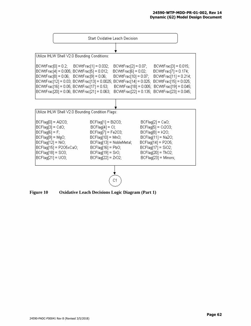
24590-WTP-MDD-PR-01-002, Rev 14 Dynamic (G2) Model Design Document
Page 62
24590-PADC-F00041 Rev 8 (Revised 3/5/2018)
Figure 10 Oxidative Leach Decisions Logic Diagram (Part 1)
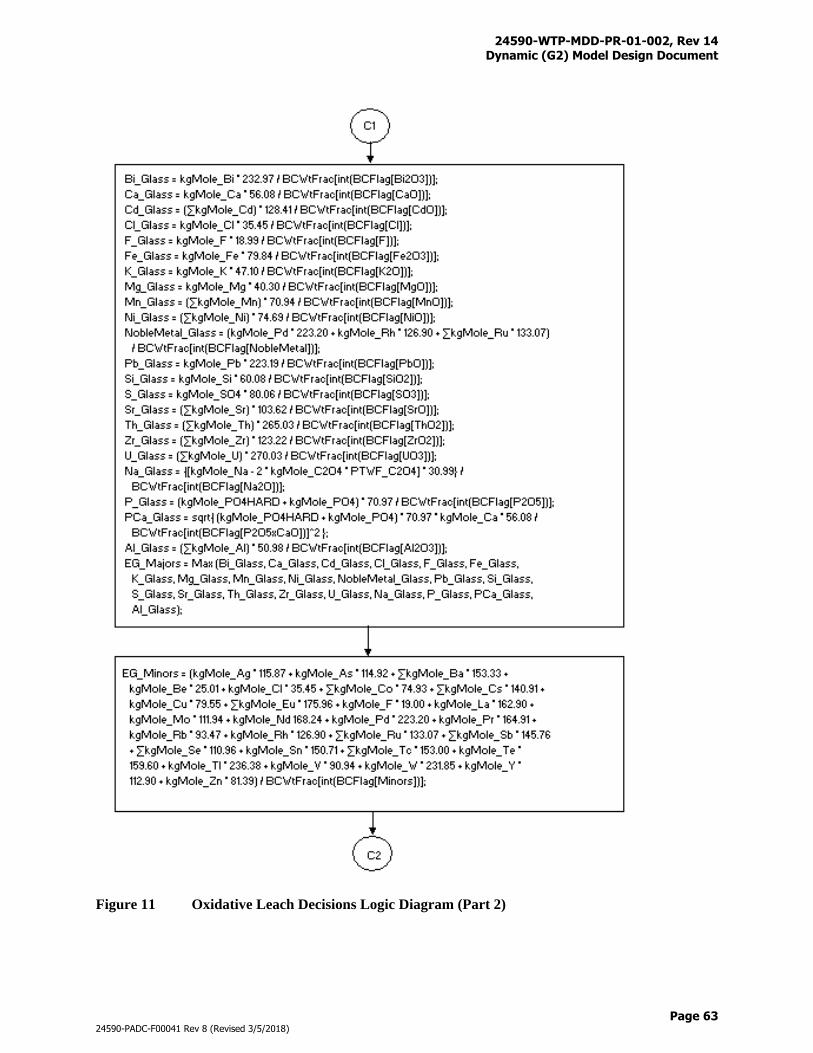
24590-WTP-MDD-PR-01-002, Rev 14 Dynamic (G2) Model Design Document
Page 63
24590-PADC-F00041 Rev 8 (Revised 3/5/2018)
Figure 11 Oxidative Leach Decisions Logic Diagram (Part 2)
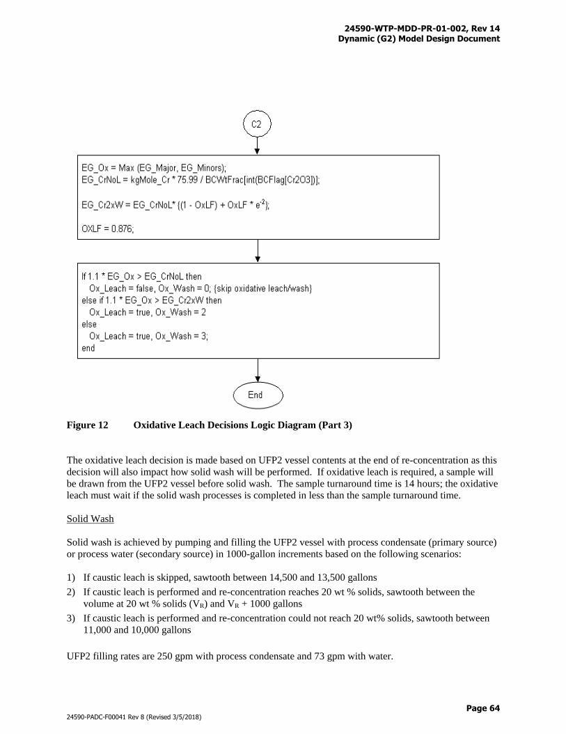
24590-WTP-MDD-PR-01-002, Rev 14 Dynamic (G2) Model Design Document
Page 64
24590-PADC-F00041 Rev 8 (Revised 3/5/2018)
Figure 12 Oxidative Leach Decisions Logic Diagram (Part 3)
The oxidative leach decision is made based on UFP2 vessel contents at the end of re-concentration as this
decision will also impact how solid wash will be performed. If oxidative leach is required, a sample will
be drawn from the UFP2 vessel before solid wash. The sample turnaround time is 14 hours; the oxidative
leach must wait if the solid wash processes is completed in less than the sample turnaround time.
Solid Wash
Solid wash is achieved by pumping and filling the UFP2 vessel with process condensate (primary source)
or process water (secondary source) in 1000-gallon increments based on the following scenarios:
1) If caustic leach is skipped, sawtooth between 14,500 and 13,500 gallons
2) If caustic leach is performed and re-concentration reaches 20 wt % solids, sawtooth between the
volume at 20 wt % solids (VR) and VR + 1000 gallons
3) If caustic leach is performed and re-concentration could not reach 20 wt% solids, sawtooth between
11,000 and 10,000 gallons
UFP2 filling rates are 250 gpm with process condensate and 73 gpm with water.
24590-WTP-MDD-PR-01-002, Rev 14 Dynamic (G2) Model Design Document
Page 65
24590-PADC-F00041 Rev 8 (Revised 3/5/2018)
Solid wash is divided into two stages: 1) wash forward, and 2) wash recycle. Permeate is routed to the
UFP-VSL-00062 vessels during wash forward and to the PWD-VSL-00015/16 vessels during wash
recycle. Wash volumes depend on waste conditions at the end of solids concentration or re-concentration
and if subsequent oxidative leach is required. The minimum volume for wash recycle is 1,000-gallons.
If subsequent oxidative leach is required:
Total wash volume is set to wash until [OH-] reaches 0.25M
Permeate will be fed forward if any of the following are true:
– [Na+] ≥ 3.8M, or
– [Na+] ≥ 0.5 * sodium concentration at end of solids concentration, or
– [PO4-3] ≥ 0.4 * peak phosphate concentration, or
– [C2O4-2] ≥ 0.4 * peak oxalate concentration
Permeate will be recycled until [OH-] ≤ 0.25M
Wash recycle may or may not be needed, depending on the wash forward volume, e.g., skip wash
recycle if wash forward volume equals to total wash volume
If subsequent oxidative leach is not required:
2.8 * V_slurry ≤ total wash volume ≤ V_max
Wash forward if any of the following are true:
– [Na+] ≥ 3.8M, or
– [Na+] ≥ 0.5 * sodium concentration at the end of re-concentration, or
– [PO4-3] ≥ 0.4 * peak phosphate concentration, or
– [C2O4-2] ≥ 0.4 * peak oxalate concentration
Permeate will be recycled until total wash volume has been applied
Skip wash recycle if wash forward volume equals to total wash volume
Where:
V_slurry = Slurry volume at the end of solids concentration (gal)
V_max = Maximum wash volume (gal)
Peak concentrations are defined as the highest dissolved phase oxalate and phosphate concentrations
achieved during wash. It is not necessarily true that peak concentrations occur at the beginning of wash.
In fact, dissolve phase oxalate and phosphate concentrations decline initially, then spike, and finally
recede. This phenomenon occurs for batches with reasonable solid phase oxalate and phosphate at the
beginning of wash, due to dilution and dissolution.
If the current batch is not phosphate limiting,
V_max = least of {(4.5 * V_slurry), (0.25M [OH-])}
otherwise
V_max = least of {(4.5 * V_slurry), (0.25M [OH-]), (0.1 * peak [PO4-3])}
The following method is applied to determine if the current batch will form phosphate limiting IHLW
glass.
24590-WTP-MDD-PR-01-002, Rev 14 Dynamic (G2) Model Design Document
Page 66
24590-PADC-F00041 Rev 8 (Revised 3/5/2018)
EG-P = (PO4-3(HARD) + PO4-3(s) + PO4-3(l)) * 70.97 / FLAG-P2O5 (Eq. 36)
EG-O = MAX (
Fe+3 * 79.84 / MAX(FLAG-FE2O3, 0.1375),
Zr+4 * 123.22 / FLAG-ZrO2,
U(Total) * 270.03 / FLAG-UO3,
Th+4 * 265.03 / FLAG-ThO2,
Ca+2 * 56.08 / FLAG-CaO,
Ni+2 * 74.69 / FLAG-NiO,
Pb+2 * 223.19 / FLAG-PbO2,
Bi+3 * 232.97 / FLAG-Bi2O3,
F- * 18.99 / FLAG-F,
SO4-2 * 80.06 / FLAG-SO3,
(Na+ - (2 * C2O4-2(s) * PTWF-C2O4)) * 30.99 + K+ * 47.09) / FLAG-Na2O,
(AlOH3 + Al+3(s))* 50.98 / FLAG-Al2O3,
(Cr(Total) + Cr+3(l)) * 75.99 / FLAG-Cr2O3,
) (Eq. 37)
Where:
EG-P = The estimated glass produced from phosphate (kg)
EG-O = The estimated glass produced from other wastes in solids (kg)
Individual element quanities (i.e., Fe+3) units are in kg-mole
FLAG-“x” is the HLW glass limiting oxide value set in G2 as wt fraction units
Multiplier values are in kg oxide / kg-mole element
PTWF-C2O4 is a wash factor for solid oxalate in Pretreatment
If EG-P ≥ 1.01 * EG-O and PO4-3 (s) > 0.01 * PO4-3(HARD) (s) then
phosphate limited glass = true
else
phosphate limited glass = false
To ensure phase equilibrium, solubility corrections are applied at 45 °C during wash. It is important to
note that oxalate and phosphate tend to dissolve as wash progresses when aqueous phase sodium is
washed out, but aluminate tends to precipitate as hydroxide concentration also goes down. Section 3.7.16
states that it is desirable to send more of the soluble constituents to the LAW Facility with the goal of
keeping a balance among the WTP mission, IHLW glass production, solids reprecipitation and line
plugging factors.
To prevent aluminum precipitation, 19M NaOH (Na = waste sodium) is added to the UFP2 vessel during
wash until the current aluminate concentration is less than / equal to 8% of its concentration at end of
solids concentration or re-concentration, e.g., 92% of the aluminate has been washed out. The caustic is
added on an as needed basis to keep aluminate unsaturated. Further discussions are provided later in this
section for the sodium dilution and caustic addition operations in UFP-VSL-00062 to prevent solids
precipitation.
Slurries will be concentrated to 20 wt % solids if possible at the end of the wash. For batches not
requiring oxidative leach, skip to solid discharge.
Oxidative Leach
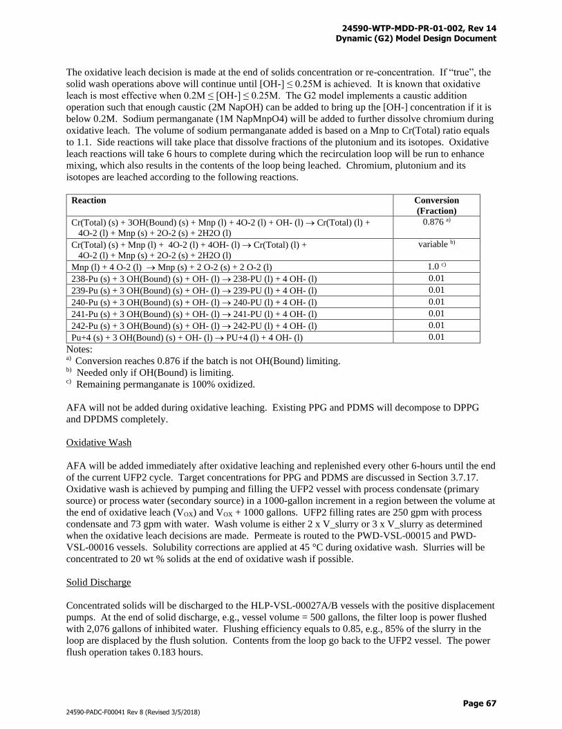
24590-WTP-MDD-PR-01-002, Rev 14 Dynamic (G2) Model Design Document
Page 67
24590-PADC-F00041 Rev 8 (Revised 3/5/2018)
The oxidative leach decision is made at the end of solids concentration or re-concentration. If “true”, the
solid wash operations above will continue until [OH-] ≤ 0.25M is achieved. It is known that oxidative
leach is most effective when 0.2M ≤ [OH-] ≤ 0.25M. The G2 model implements a caustic addition
operation such that enough caustic (2M NapOH) can be added to bring up the [OH-] concentration if it is
below 0.2M. Sodium permanganate (1M NapMnpO4) will be added to further dissolve chromium during
oxidative leach. The volume of sodium permanganate added is based on a Mnp to Cr(Total) ratio equals
to 1.1. Side reactions will take place that dissolve fractions of the plutonium and its isotopes. Oxidative
leach reactions will take 6 hours to complete during which the recirculation loop will be run to enhance
mixing, which also results in the contents of the loop being leached. Chromium, plutonium and its
isotopes are leached according to the following reactions.
Reaction Conversion
(Fraction)
Cr(Total) (s) + 3OH(Bound) (s) + Mnp (l) + 4O-2 (l) + OH- (l) Cr(Total) (l) +
4O-2 (l) + Mnp (s) + 2O-2 (s) + 2H2O (l)
0.876 a)
Cr(Total) (s) + Mnp (l) + 4O-2 (l) + 4OH- (l) Cr(Total) (l) +
4O-2 (l) + Mnp (s) + 2O-2 (s) + 2H2O (l)
variable b)
Mnp (l) + 4 O-2 (l) Mnp (s) + 2 O-2 (s) + 2 O-2 (l) 1.0 c)
238-Pu (s) + 3 OH(Bound) (s) + OH- (l) 238-PU (l) + 4 OH- (l) 0.01
239-Pu (s) + 3 OH(Bound) (s) + OH- (l) 239-PU (l) + 4 OH- (l) 0.01
240-Pu (s) + 3 OH(Bound) (s) + OH- (l) 240-PU (l) + 4 OH- (l) 0.01
241-Pu (s) + 3 OH(Bound) (s) + OH- (l) 241-PU (l) + 4 OH- (l) 0.01
242-Pu (s) + 3 OH(Bound) (s) + OH- (l) 242-PU (l) + 4 OH- (l) 0.01
Pu+4 (s) + 3 OH(Bound) (s) + OH- (l) PU+4 (l) + 4 OH- (l) 0.01
Notes: a) Conversion reaches 0.876 if the batch is not OH(Bound) limiting. b) Needed only if OH(Bound) is limiting. c) Remaining permanganate is 100% oxidized.
AFA will not be added during oxidative leaching. Existing PPG and PDMS will decompose to DPPG
and DPDMS completely.
Oxidative Wash
AFA will be added immediately after oxidative leaching and replenished every other 6-hours until the end
of the current UFP2 cycle. Target concentrations for PPG and PDMS are discussed in Section 3.7.17.
Oxidative wash is achieved by pumping and filling the UFP2 vessel with process condensate (primary
source) or process water (secondary source) in a 1000-gallon increment in a region between the volume at
the end of oxidative leach (VOX) and VOX + 1000 gallons. UFP2 filling rates are 250 gpm with process
condensate and 73 gpm with water. Wash volume is either 2 x V_slurry or 3 x V_slurry as determined
when the oxidative leach decisions are made. Permeate is routed to the PWD-VSL-00015 and PWD-
VSL-00016 vessels. Solubility corrections are applied at 45 °C during oxidative wash. Slurries will be
concentrated to 20 wt % solids at the end of oxidative wash if possible.
Solid Discharge
Concentrated solids will be discharged to the HLP-VSL-00027A/B vessels with the positive displacement
pumps. At the end of solid discharge, e.g., vessel volume = 500 gallons, the filter loop is power flushed
with 2,076 gallons of inhibited water. Flushing efficiency equals to 0.85, e.g., 85% of the slurry in the
loop are displaced by the flush solution. Contents from the loop go back to the UFP2 vessel. The power
flush operation takes 0.183 hours.
24590-WTP-MDD-PR-01-002, Rev 14 Dynamic (G2) Model Design Document
Page 68
24590-PADC-F00041 Rev 8 (Revised 3/5/2018)
Contents of the UFP2 vessel (Non-Newtonian fluids) from the power flush operation will be ejected to
HLP-VSL-00027A/B again by the positive displacement pumps. The transfer line is flushed with 150
gallons of inhibited water at 90 gpm after the displacement pumping. Contents of the filter loop including
the pre-isolation and post-isolation valve sections are drained to PWD-VSL-00033 at 50 gpm.
Acid Clean
Ultrafilters will be acid cleaned after 500 hours of operation i.e., cumulative usage that excludes idle
times, or after every four UFP2 cycles, whichever comes first (note: the filters will continue to be used if
the UFP2 vessel has not finished wash). At the end of solid discharge, e.g., after the first power flush
operation described above, the filter loop will be power flushed with 2,076 gallons of inhibited water a
second time. Flushing efficiency equals to 0.85, e.g., 85% of the slurry in the loop are displaced by the
flush solution. Contents from the loop go back to the UFP2 vessel. The power flush operation takes
0.183 hours.
Contents of the UFP2 vessel (Non-Newtonian Fluids) from the power flush operation will be transferred
to HLP-VSL-00027A/B by the positive displacement pumps. The transfer line is flushed with 150
gallons of inhibited water at 90 gpm after the displacement pumping. Contents of the filter loop including
the pre-isolation and post-isolation valve sections are drained to PWD-VSL-00033 at 50 gpm.
The UFP2 vessel will be filled with 17,076 gallons of 2M nitric acid which will then be circulated in the
loop for 1.5 hours. The acid clean solutions (Newtonian Fluids) will be transferred to PWD-VSL-
00015/16 with the positive displacement pump.
Contents of the filter loop including the pre-isolation and post-isolation valve sections are drained to
PWD-VSL-00033 at 80 gpm. Remaining acidic contents in the UFP2 vessel will be neutralized with 50
gallons of 19M caustic (NapOH) based on the reaction below:
H+ (l) + OH- (l) → H2O (l)
After acid neutralization, the UFP2 vessel will be available to start the next cycle.
Vessel Tag # Equipment Description
UFP-VSL-00062A Ultrafiltration Permeate Collection Vessel -
Supertank combines UFP-VSL-00062A/B/C
and CXP-VSL-00004 operations
The G2 model implements a WTP design modification that mitigates solids precipitation for feeds to the
ion exchange columns (IXC). In this design modification ultrafiltration permeates are routed to the
Permeate Collection Vessels (UFP-VSL-00062A/B/C), then to CXP-VSL-00004. Wash recycle and
oxidative wash permeates are routed directly to PWD-VSL-00015 and PWD-VSL-00016. CXP-VSL-
00004 will discharge to the IXC through a guard file (CXP-FILT-00001).
Permeate exiting CXP-FILT-00001 will be split into two streams, one is fed forward to the IXC while the
other is recycled through a heat exchanger. The stream through the heat exchanger will be split again,
one part goes directly to CXP-VSL-00004 and another part to UFP-VSL-00062A/B/C. The recycle
operation mixes the UFP-VSL-00062A/B/C and CXP-VSL-00004 contents to virtually identical
compositions and same temperature, as a result, a “Supertank” is created in the model to represent this
group-of-four vessels.
24590-WTP-MDD-PR-01-002, Rev 14 Dynamic (G2) Model Design Document
Page 69
24590-PADC-F00041 Rev 8 (Revised 3/5/2018)
The Supertank which combines the working volumes of UFP-VSL-00062A/B/C and CXP-VSL-00004
receives solids concentration, reconcentration, and wash forward permeates and discharges directly to the
guard filter. When the ultrafilter trains are working in parallel, both permeate streams are placed in the
“Super Tank” at the same time. It operates at 50 oC in a continuous mode (although solubilities are
applied at 45 oC due to lack of data for correlation curve fits), meaning that it can receive and discharge at
the same time. The Supertank is named after the UFP-VSL-00062A vessel with the following working
volumes:
Vmin = 11,755 gallons
Vset = 12,000 gallons
Vmax = 78,775 gallons
A headspace (15,000 gallons) is reserved for the sodium dilution and caustic addition operations below
and the ion exchange displacement operations in Section 3.8.4.
Sodium Dilution
The feed to CXP must meet a maximum sodium concentration target. Process condensate (primary
source) or process water (secondary source) will be added for dilution if sodium concentration in the
vessel is greater than 8M. Filling rates are 250 gpm with process condensate and 73 gpm with water.
Volumes for dilution vary from batch to batch depending on conditions of the ultrafilter permeates as well
as the caustic addition operations below. Dilution will continue until [Na+] ≤ 8M or the maximum
volume of the vessel has been reached.
Process condensate or process water will also be added to prevent oxalate and phosphate precipitation.
The volume of water added is determined to ensure that dissolved C2O4-2 and PO4
-3 are unsaturated or at
equilibrium.
Caustic Addition
Aluminate tends to precipitate when OH- concentration is diluted as the result of sodium dilution above.
Provided that the maximum volume of vessel is not reached, enough caustic (19M NaOH, defined as
waste sodium) will be added to prevent the following reaction from taking place:
Al(OH)4-(l) → Al(OH)3 (s) + OH- (l)
This caustic addition may increase the sodium concentration to above the 8M target value.
An iterative approach is taken to continue the sodium dilution and caustic addition operations until
sodium concentration ≤ 8M and C2O4-2, PO4
-3, and Al(OH)4- do not precipitate or the maximum volume of
the vessel is reached. Because the “Super Tank” is modeled as a continuous tank, dilution and caustic
addition are evaluated continuously when it is running.
The Supertank discharges to the ion exchange columns through CXP-FILT-00001 at a fixed flow rate at
30 gpm.
Figure F-5 provides a graphical illustration of the UFP system where connections with upstream and
downstream systems are shown. Table N-1 provides the totalizer files that are used to track the process
streams and material flows into and out of the UFP.
24590-WTP-MDD-PR-01-002, Rev 14 Dynamic (G2) Model Design Document
Page 70
24590-PADC-F00041 Rev 8 (Revised 3/5/2018)
3.8.4 Cesium Removal Using Ion Exchange Process (CXP) System (Inactive)
The purpose of the Cesium Ion Exchange System is to remove cesium (Cs-134, Cs-137, and Cs+) that is
in the solution. Because cesium is soluble, it cannot be removed by ultrafiltration and an ion exchange
(IX) process is used. These elements need to be removed to meet LAW vitrification shielding and glass
product requirements, and are sent to the HLW melter.
Vessel Tag # Equipment Description
CXP-VSL-00004 Cesium Ion Exchange Caustic Rinse Collection Vessel
CXP-FILT-00001 Cesium Ion Exchange Guard Filter
The WTP has implemented design changes that remove CXP-VSL-00001 from the flowsheet, utilize
CXP-VSL-00004 as the cesium ion exchange feed vessel, utilize CXP-VSL-00005 to supply caustic for
IX displacement, add heating and recycling equipment for mixing of ion exchange feeds, and add an in-
line guard filter between CXP-VSL-00004 and the IX columns (see Figure F-8 for illustration). The
Cesium Ion Exchange Caustic Rinse Collection Vessel now receives feeds from UFP-VSL-00062A, UFP-
VSL-00062B, and UFP-VSL-00062C. One main objective of the heating and recycling operations is to
mix permeate from various UFP2 operations such as solids concentration, reconcentration, and wash
forward in the group-of-four vessels. For modeling simplicity, the group-of-four vessels are combined
into a large vessel called “Super Tank”. For details of the “Super Tank” operations, refer to Section
3.8.3.
Feeds to the IX columns from the Super Tank are routed through CXP-FILT-00001. The CXP-FILT-
00001 filter housing has a 117-gallon holding capacity. The filter housing is empty before startup and
after each back flush operation. It is assumed that 100% of the solids from the Super Tank is captured by
CXP-FILT-00001. It is anticipated that filter cakes need to be removed by the back flush operations after
34 UFP2 batches have been processed (here a UFP2 batch is defined as the completion of a solids
concentration cycle by an ultrafiltration train).
During model runs, the current-batch attribute of CXP-FILT-00001 increments after each UFP2 batch is
processed. A filter back flush analyzer logic procedure keeps track of the current-batch value
continuously. When current-batch reaches the target at 34, a back flush operation is triggered. During a
back flush, all the liquid and solid in CXP-FILT-00001 are transferred to PWD-VSL-00016, along with
80 gallons of 0.1M NapOH. The back flush operation takes 0.25 hours. The transfer is made as long as
PWD-VSL-00016 has sufficient storage to receive, regardless if the vessel is currently in receive or
discharge mode. pH adjustment will not be made in PWD-VSL-00016 after a transfer if it receives in
discharge mode due to the use of diluted caustic for back flush.
At the end of a back flush, the back flush clock starts to tick. If 24 hours have elapsed and current-batch
is still at 34 (e.g., UFP2 has not finished the current solids concentration cycle), then a second back flush
will be performed. This 24-hour interval back flush continues until current-batch do not equal to 34
(current-batch is reset to 0 at the end of batch 34).
Vessel Tag # Equipment Description
CXP-IXC-00001 Cesium Ion Exchange Column
CXP-IXC-00002 Cesium Ion Exchange Column
CXP-IXC-00003 Cesium Ion Exchange Column
CXP-IXC-00004 Cesium Ion Exchange Column
The cesium ion exchange columns operate in carousel patterned cycles such that the loading columns are
in “lead”, “lag”, and “polishing” positions while the regenerating column goes through displacement, pre-
24590-WTP-MDD-PR-01-002, Rev 14 Dynamic (G2) Model Design Document
Page 71
24590-PADC-F00041 Rev 8 (Revised 3/5/2018)
elution rinse, elution, post-elution rinse, and regeneration. Once the loading is completed, the lead
column enters regeneration, the lag column becomes the lead, the polishing column becomes the lag, and
the regenerating column becomes the polishing column.
Each column consists of a 600-gallon resin bed and a 480-gallon headspace. The headspace is initially
filled with regeneration solutions (0.5M NapOH). It is assumed that plug flow occurs within the resin bed
region while mixing can occur in the headspace.
Feed from the in-line guard filter is routed through the loading columns in the lead, lag, and polishing
order. The feed pump runs at a fixed flow rate at 30 gpm. In the beginning of each loading cycle, 1,500
gallons, e.g., 2.5 column volumes (cv) of ion exchange effluent will be recycled to the supertank from the
polishing column. After that, treated waste from the polishing column is sent to CXP-VSL-00026A,
CXP-VSL-00026B, and CXP-VSL-00026C. Overall cesium removal efficiency of the loading columns
equals to 99.9766%. For modeling purpose, it is assumed that ion exchange only occurs within the lead
column. Loading volume is determined based on the cesium and potassium concentrations of the feed at
the start of a cycle (Equations 38, 39, and 40).
A = 53604 - 94180 [K+] (Eq. 38)
B = 361837 - 720514 [K+] (Eq. 39)
Vload = -A Ln([Cs+]) - B (Eq. 40)
Where:
A = Constant (gallons)
B = Constant (gallons)
[K+] = Waste feed potassium concentration (gmol/L)
[Cs+] = Waste feed overall cesium concentration (gmol/L)
The loading cycle may terminate before Vload is reached if cumulated radioactivity contributed by 137-Cs
reaches 75,000 curries.
The resin bed is packed with Spherical Resorcinol-Formaldehyde Resin (RF) that is saturated with
process sodium (Nap+) initially and during regeneration. At saturation the column contains 4.63 kg-
moles sodium which is equivalent to 6.8 mmole/g dry H-form resin. Ion exchange takes place where
cesium and potassium ions replace the sodium ion during the loading cycle.
{R}-Nap (absorbed) + 134-Cs (l) → {R}-134-Cs (absorbed) + Nap+ (l)
{R}-Nap (absorbed) + 137-Cs (l) → {R}-137-Cs (absorbed) + Nap+ (l)
{R}-Nap (absorbed) + Cs+ (l) → {R}-Cs (absorbed) + Nap+ (l)
{R}-Nap (absorbed) + K+ (l) → {R}-K (absorbed) + Nap+ (l)
{R}-Nap (absorbed) + 137m-Ba (l) → {R}-137m-Ba (absorbed) + Nap+ (l)
Where:
{R} = RF resin (inert)
For every kg-mole of 134-Cs, 137-Cs, 137m-Ba, Cs+ and K+ captured during ion exchange, 1 kg-mole of
Nap+ is released from the resin surface. The mass balances of the ion exchange within the lead column
are given below:
Start of Loading Cycle
24590-WTP-MDD-PR-01-002, Rev 14 Dynamic (G2) Model Design Document
Page 72
24590-PADC-F00041 Rev 8 (Revised 3/5/2018)
Loading_Nap+ = 4.63 kg-moles/column
Loading_Cs134 = 0.0 kg-moles/column
Loading_Cs137 = 0.0 kg-moles/column
Loading_Cs+ = 0.0 kg-moles/column
Loading_mBa137 = 0.0 kg-moles/column
Loading_K+ = 0.0 kg-moles/column
End of Loading Cycle
Loading_Cs134 = 0.999766 Cs134_Input
Loading_Cs137 = 0.999766 Cs137_Input
Loading_Cs+ = 0.999766 Cs+_Input
Loading_mBa137 = 1.526e-7 Loading_Cs137
Loading_K+ = 100 percent removal until the end of loading cycle or QK (Eq. 47) reaches Loading_Nap+
= 4.63 – Loading_Cs134 – Loading_Cs137 – Loading_Cs+ - Loading_K+
The cesium loadings are determined based on the actual cesium input to the lead column from the
Supertank. The QCs in Eq. 44 is not used as the value is estimated using the concentrations of cesium and
hydroxide at the start of the loading cycle. This guarantees that the target removal efficiency can be
achieved for the entire loading cycle.
Potassium is captured at a 100% removal efficiency until the end of loading cycle or the maximum
loading for K+ is reached whichever comes first. QK is calculated as follows:
a2a1
2
w
a2
w
a2
w
NaHR
K K
1
][OH
K
K
1
][OH
K1
K
1
][OH
K
F (Eq. 41)
a2a1
2
w
a2
w
Na2R
K K
1
][OH
K
K
1
][OH
K1
1F (Eq. 42)
2
2FFF Na2RNaHR
SA
(Eq. 43)
bedbed
loadCs
CsV ρ
V ][Cs ξQ
(Eq. 44)
696.0
WasteNa
K
][Na
][K(1.52)
Q
Q
(Eq. 45)
24590-WTP-MDD-PR-01-002, Rev 14 Dynamic (G2) Model Design Document
Page 73
24590-PADC-F00041 Rev 8 (Revised 3/5/2018)
1Q
Q
QQFQ
Na
K
CstotalSA
Na (Eq. 46)
1000/3.0*2271*)QQQF(Q NaCstotalSAK (Eq. 47)
Where:
Ka1 = 10-10.6 (gmol/L)
Ka2 = 10-13.2 (gmol/L)
Kw = 10-14 (gmol2/L2)
Vload = Calculated using Eq. 40
ξCs = Cesium removal efficiency (0.999766)
FSA = Resin disassociation constant (unitless)
ρbed = 0.3 (kg H-form resin/L wet Na-form resin)
Vbed = 2271 (L)
Qtotal = 6.8 (mmol/g dry H-form resin)
[OH-], [134-Cs], [137-Cs], [Cs+], [K+], and [Na+] are concentrations of feed at the start of a loading
cycle.
At the end of a loading cycle, resins are regenerated following the steps below:
1) Displacement
2) Resin outlet flush #1
3) Pre-elution rinse
4) Elution
5) Resin outlet flush #2
6) Post-elution rinse
7) Resin outlet flush #3
8) Regeneration
9) Regeneration fluid displacement
10) Resin outlet flush #4
The displacement cycle is performed in order to prevent aluminum precipitation during the pre-elution
rinse cycle. During the displacement cycle, 0.1M NapOH that comes from CXP-VSL-00005 is routed
through the column to displace the pore liquids. Three column volumes of fluid are processed through the
column at a rate of 3 CV/hr. The displaced solution is routed to the Supertank. At the end of
displacement, the lead column outlet is flushed the first time with 21 gallons of demineralized water. The
outlet is flushed at 30 gpm flow rate and is routed to the Supertank.
The pre-elution rinse cycle is performed in order to prevent acidic eluant solution from reacting during
elution with caustic waste solution residing in the column. During the pre-elution rinse cycle,
demineralized water from a chem-add is routed to the column to remove the pore liquids. Two CV of
DIW are processed at a rate of 3 CV/hr. The exiting material is routed to PWD-VSL-00015 or PWD-
VSL-00016, depending on their availability. After 2 CV of pre-elution rinse DIW is processed, the
elution cycle starts.
24590-WTP-MDD-PR-01-002, Rev 14 Dynamic (G2) Model Design Document
Page 74
24590-PADC-F00041 Rev 8 (Revised 3/5/2018)
During the elution cycle, 15 CV of 0.45M HNO3 from the Cesium Evaporator Recovered Nitric Acid
Vessel (CNP-VSL-00004) is routed to the column at a rate of 1 CV/hr. Ion exchange takes place where
hydrogen ions replace cesium, potassium, and sodium ions in accordance with the reactions below.
{R}-134-Cs (absorbed) + H+ (l) → {R}-H + 134-Cs (l)
{R}-137-Cs (absorbed) + H+ (l) → {R}-H + 137-Cs (l)
{R}-Cs (absorbed) + H+ (l) → {R}-H + Cs+ (l)
{R}-K (absorbed) + H+ (l) → {R}-H + K+ (l)
{R}-137m-Ba (absorbed) + H+ (l) → {R}-H + 137m-Ba (l)
{R}-Nap (absorbed) + H+ (l) → {R}-H + Nap+
The ion exchange reactions are charge balanced such that for every kg-mole of H+ captured, 1 kg-mole of
134-Cs, 137-Cs, Cs+, 137m-Ba, K+, and Nap+ is released from the resin surface. An instant
neutralization step is added to the elution process, for example, any H+ from the HNO3 source will first
react with the residual OH-, then replace the captured 137-Cs, 134-Cs, Cs+, 137m-Ba, K+, and Nap+ (up
to the resin capacity at 4.63 kg-moles Na+ equivalent per column). H+ ion can only breakthrough when
the neutralization step is completed. The breakthrough of 134-Cs, 137-Cs, Cs+, 137m-Ba, K+ and Nap+
from the regeneration column follow the relationship shown in Figure 13 and Table 16 (24590-WTP-
MCR-PE-13-0030). The 137m-Ba breakthrough is assumed to follow cesium.
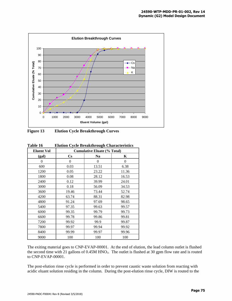
24590-WTP-MDD-PR-01-002, Rev 14 Dynamic (G2) Model Design Document
Page 75
24590-PADC-F00041 Rev 8 (Revised 3/5/2018)
Figure 13 Elution Cycle Breakthrough Curves
Table 16 Elution Cycle Breakthrough Characteristics
Eluent Vol Cumulative Eluate (% Total)
(gal) Cs Na K
0 0 0 0
600 0.03 13.51 6.38
1200 0.05 23.22 11.36
1800 0.08 28.12 16.53
2400 0.12 39.99 24.01
3000 0.18 56.09 34.53
3600 19.46 73.44 52.74
4200 63.74 88.31 82.98
4800 91.24 97.69 98.65
5400 97.35 99.63 99.57
6000 99.35 99.79 99.73
6600 99.78 99.86 99.81
7200 99.92 99.9 99.87
7800 99.97 99.94 99.92
8400 99.99 99.97 99.96
9000 100 100 100
The exiting material goes to CNP-EVAP-00001. At the end of elution, the lead column outlet is flushed
the second time with 21 gallons of 0.45M HNO3. The outlet is flushed at 30 gpm flow rate and is routed
to CNP-EVAP-00001.
The post-elution rinse cycle is performed in order to prevent caustic waste solution from reacting with
acidic eluant solution residing in the column. During the post-elution rinse cycle, DIW is routed to the
Elution Breakthrough Curves
0
10
20
30
40
50
60
70
80
90
100
0 1000 2000 3000 4000 5000 6000 7000 8000 9000
Eluent Volume (gal)
Cu
mu
lati
ve E
luate
(%
To
tal) Cs
Na
K
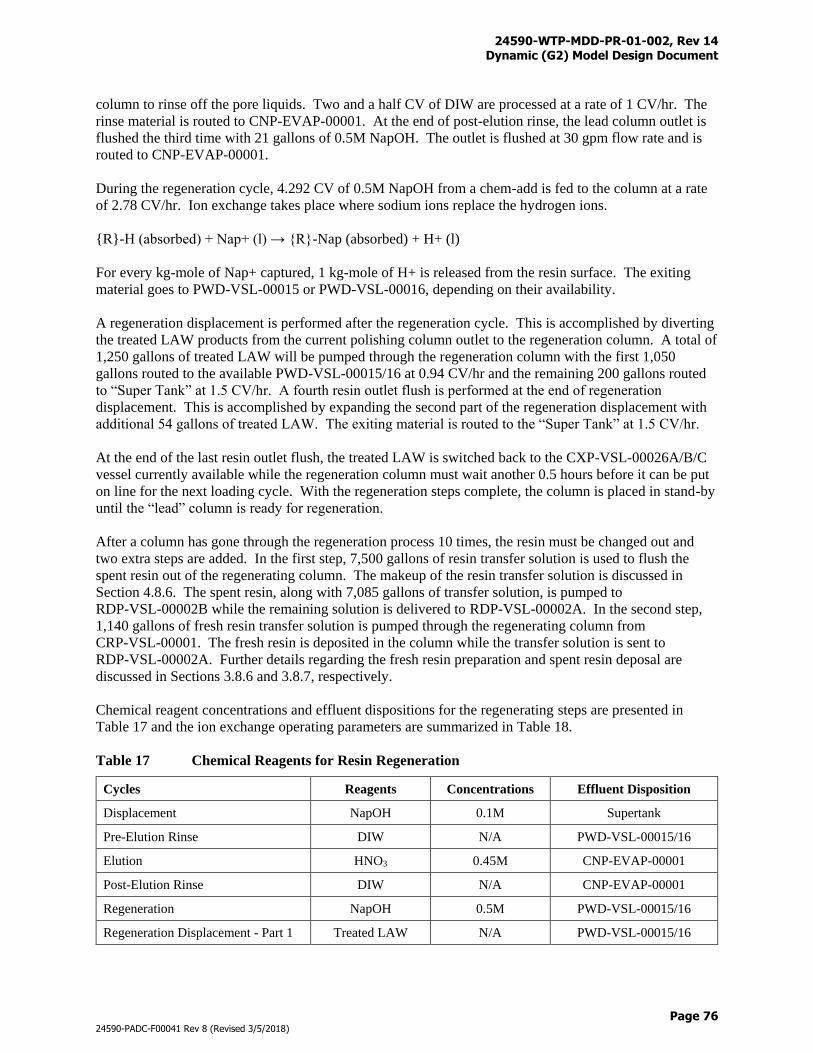
24590-WTP-MDD-PR-01-002, Rev 14 Dynamic (G2) Model Design Document
Page 76
24590-PADC-F00041 Rev 8 (Revised 3/5/2018)
column to rinse off the pore liquids. Two and a half CV of DIW are processed at a rate of 1 CV/hr. The
rinse material is routed to CNP-EVAP-00001. At the end of post-elution rinse, the lead column outlet is
flushed the third time with 21 gallons of 0.5M NapOH. The outlet is flushed at 30 gpm flow rate and is
routed to CNP-EVAP-00001.
During the regeneration cycle, 4.292 CV of 0.5M NapOH from a chem-add is fed to the column at a rate
of 2.78 CV/hr. Ion exchange takes place where sodium ions replace the hydrogen ions.
{R}-H (absorbed) + Nap+ (l) → {R}-Nap (absorbed) + H+ (l)
For every kg-mole of Nap+ captured, 1 kg-mole of H+ is released from the resin surface. The exiting
material goes to PWD-VSL-00015 or PWD-VSL-00016, depending on their availability.
A regeneration displacement is performed after the regeneration cycle. This is accomplished by diverting
the treated LAW products from the current polishing column outlet to the regeneration column. A total of
1,250 gallons of treated LAW will be pumped through the regeneration column with the first 1,050
gallons routed to the available PWD-VSL-00015/16 at 0.94 CV/hr and the remaining 200 gallons routed
to “Super Tank” at 1.5 CV/hr. A fourth resin outlet flush is performed at the end of regeneration
displacement. This is accomplished by expanding the second part of the regeneration displacement with
additional 54 gallons of treated LAW. The exiting material is routed to the “Super Tank” at 1.5 CV/hr.
At the end of the last resin outlet flush, the treated LAW is switched back to the CXP-VSL-00026A/B/C
vessel currently available while the regeneration column must wait another 0.5 hours before it can be put
on line for the next loading cycle. With the regeneration steps complete, the column is placed in stand-by
until the “lead” column is ready for regeneration.
After a column has gone through the regeneration process 10 times, the resin must be changed out and
two extra steps are added. In the first step, 7,500 gallons of resin transfer solution is used to flush the
spent resin out of the regenerating column. The makeup of the resin transfer solution is discussed in
Section 4.8.6. The spent resin, along with 7,085 gallons of transfer solution, is pumped to
RDP-VSL-00002B while the remaining solution is delivered to RDP-VSL-00002A. In the second step,
1,140 gallons of fresh resin transfer solution is pumped through the regenerating column from
CRP-VSL-00001. The fresh resin is deposited in the column while the transfer solution is sent to
RDP-VSL-00002A. Further details regarding the fresh resin preparation and spent resin deposal are
discussed in Sections 3.8.6 and 3.8.7, respectively.
Chemical reagent concentrations and effluent dispositions for the regenerating steps are presented in
Table 17 and the ion exchange operating parameters are summarized in Table 18.
Table 17 Chemical Reagents for Resin Regeneration
Cycles Reagents Concentrations Effluent Disposition
Displacement NapOH 0.1M Supertank
Pre-Elution Rinse DIW N/A PWD-VSL-00015/16
Elution HNO3 0.45M CNP-EVAP-00001
Post-Elution Rinse DIW N/A CNP-EVAP-00001
Regeneration NapOH 0.5M PWD-VSL-00015/16
Regeneration Displacement - Part 1 Treated LAW N/A PWD-VSL-00015/16
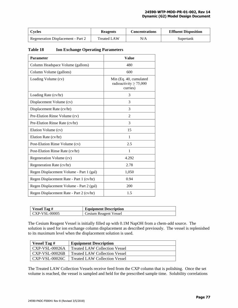
24590-WTP-MDD-PR-01-002, Rev 14 Dynamic (G2) Model Design Document
Page 77
24590-PADC-F00041 Rev 8 (Revised 3/5/2018)
Cycles Reagents Concentrations Effluent Disposition
Regeneration Displacement - Part 2 Treated LAW N/A Supertank
Table 18 Ion Exchange Operating Parameters
Parameter Value
Column Headspace Volume (gallons) 480
Column Volume (gallons) 600
Loading Volume (cv) Min (Eq. 40, cumulated
radioactivity ≥ 75,000
curries)
Loading Rate (cv/hr) 3
Displacement Volume (cv) 3
Displacement Rate (cv/hr) 3
Pre-Elution Rinse Volume (cv) 2
Pre-Elution Rinse Rate (cv/hr) 3
Elution Volume (cv) 15
Elution Rate (cv/hr) 1
Post-Elution Rinse Volume (cv) 2.5
Post-Elution Rinse Rate (cv/hr) 1
Regeneration Volume (cv) 4.292
Regeneration Rate (cv/hr) 2.78
Regen Displacement Volume - Part 1 (gal) 1,050
Regen Displacement Rate - Part 1 (cv/hr) 0.94
Regen Displacement Volume - Part 2 (gal) 200
Regen Displacement Rate - Part 2 (cv/hr) 1.5
Vessel Tag # Equipment Description
CXP-VSL-00005 Cesium Reagent Vessel
The Cesium Reagent Vessel is initially filled up with 0.1M NapOH from a chem-add source. The
solution is used for ion exchange column displacement as described previously. The vessel is replenished
to its maximum level when the displacement solution is used.
Vessel Tag # Equipment Description
CXP-VSL-00026A Treated LAW Collection Vessel
CXP-VSL-00026B Treated LAW Collection Vessel
CXP-VSL-00026C Treated LAW Collection Vessel
The Treated LAW Collection Vessels receive feed from the CXP column that is polishing. Once the set
volume is reached, the vessel is sampled and held for the prescribed sample time. Solubility correlations
24590-WTP-MDD-PR-01-002, Rev 14 Dynamic (G2) Model Design Document
Page 78
24590-PADC-F00041 Rev 8 (Revised 3/5/2018)
are applied at 45 °C before the vessel can be discharged. The Treated LAW Collection Vessels transfer
feed to TLP-SEP-00001 one at a time. Flowrate is set to 34 gpm for feed-only pumping or 30 gpm for
dual pumping. Feed-only pumping is performed when recycles from TLP-VSL-00009A and TLP-VSL-
00009B are not ready for discharging. Dual pumping is performed when both treated LAW feed and
recycle are fed to the TLP evaporator. Details of the dual pumping logic are discussed in Sections 3.8.8
and 3.8.9.
Figures F-8 and F-11 provide graphical illustrations of the CXP system where connections with upstream
and downstream systems are shown. Table N-1 provides the totalizer files that are used to track the
process streams and material flows into and out of the CXP.
3.8.5 Cesium Nitric Acid Recovery Process (CNP) System (Inactive)
Vessel Tag # Equipment Description
CNP-EVAP-00001 Cesium Evaporator Separator Vessel
CNP-DISTC-00001 Cesium Evaporator Nitric Acid Rectifier
CNP-VSL-00003 Cesium Concentrate Storage Vessel
CNP-VSL-00004 Cesium Evaporator Recovered Nitric Acid Vessel
The process steps for the operation of the CNP are presented below:
1) CNP-EVAP-00001 is charged with 2,128 gallons of 5M HNO3 from a chem-add source.
2) Waste from the CXP column elution and post-elution rinse is routed to CNP-EVAP-00001.
3) The rectifier column is modeled based on a material balance typical for a simple distillation tower
(i.e., the column performance is based on the nitric acid recovery efficiency and bottoms
composition). The HNO3 recovery efficiency is applied to the G2 model at 99.5 %. The split of
water in CNP-DISTC-00001 is dependent upon the amount of [H+] and [NO3-] in the column so that
the resulting solution to CNP-VSL-00004 is 0.5M HNO3. Distillate is recycled to PWD-VSL-00015
or PWD-VSL-00016 depending on their availability.
4) CNP-VSL-00004 provides the source of nitric acid for CXP column resin elution. The vessel
receives recycle from the rectifier column and operates between the upper set volume at 7,342 gallons
and the lower set volume at 5,342 gallons. The vessel is filled initially to the lower set volume with
0.45M HNO3 from a chem-add source and is replenished when the volume reaches below the lower
set volume.
5) Once the Z value in Eq. 53 reaches above the 80 % saturation limit, the evaporator makes itself
available to empty (step 6), until then the evaporator continues to collect eluant and rinse solution
(step 2).
6) The contents of the evaporator are discharged to CNP-VSL-00003, then to HLP-VSL-00028 or HLP-
VSL-00027B in priority order depending on the following conditions: a) If HLP-VSL-00028 is in the
beginning of a “fill” cycle, for example the volume is at or slightly above the 27,000-gallon heel, b) If
HLP-VSL-00027B is in “fill” mode, and the volume of HLP-VSL-00027B is greater than 61,800
gallons, and the remaining volume of HLP-VSL-00027B can receive up to 2,615 gallons of CNP
concentrate plus the associated caustic for neutralization. The maximum volume of CNP-VSL-00003
that can be discharged in one batch is 2,615 gallons, which limits the reaction heat generated from the
neutralization. Before discharging, 19M NapOH will be added to the receiving HLW Lag Storage or
Feed Blending Process System (HLP) vessel. The volume of caustic is determined based on an OH-
to H+ ratio = 1.1 to 1, excluding the OH- already in the receiving HLP vessel. Refer to Section
4.8.12 for further details on acid neutralization.
7) The evaporator sets itself to recharge with acid (step 1).
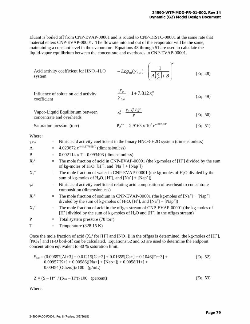
24590-WTP-MDD-PR-01-002, Rev 14 Dynamic (G2) Model Design Document
Page 79
24590-PADC-F00041 Rev 8 (Revised 3/5/2018)
Eluant is boiled off from CNP-EVAP-00001 and is routed to CNP-DISTC-00001 at the same rate that
material enters CNP-EVAP-00001. The flowrate into and out of the evaporator will be the same,
maintaining a constant level in the evaporator. Equations 48 through 51 are used to calculate the
liquid-vapor equilibrium between the concentrate and overheads in CNP-EVAP-00001.
Acid activity coefficient for HNO3-H2O
system
2
10
1)(
BALog
wc
ac
x
xAW
(Eq. 48)
Influence of solute on acid activity
coefficient
n
c
AW
a x812.71
(Eq. 49)
Vapor-Liquid Equilibrium between
concentrate and overheads P
Pxx
satA
acaa
o
(Eq. 50)
Saturation pressure (torr) PAsat = 2.9163 x 10⁸ e-4592.6/T (Eq. 51)
Where:
AW = Nitric acid activity coefficient in the binary HNO3-H2O system (dimensionless)
A = 4.029672 e-444.877899/T (dimensionless)
B = 0.002114 T - 0.093403 (dimensionless)
Xca = The mole fraction of acid in CNP-EVAP-00001 (the kg-moles of [H+] divided by the sum
of kg-moles of H2O, [H+], and [Na+] + [Nap+])
Xcw = The mole fraction of water in CNP-EVAP-00001 (the kg-moles of H2O divided by the
sum of kg-moles of H2O, [H+], and [Na+] + [Nap+])
a = Nitric acid activity coefficient relating acid composition of overhead to concentrate
composition (dimensionless)
Xcn = The mole fraction of sodium in CNP-EVAP-00001 (the kg-moles of [Na+] + [Nap+]
divided by the sum of kg-moles of H2O, [H+], and [Na+] + [Nap+])
Xoa = The mole fraction of acid in the offgas stream of CNP-EVAP-00001 (the kg-moles of
[H+] divided by the sum of kg-moles of H2O and [H+] in the offgas stream)
P = Total system pressure (70 torr)
T = Temperature (328.15 K)
Once the mole fraction of acid (Xoa for [H+] and [NO3
-]) in the offgas is determined, the kg-moles of [H+],
[NO3-] and H2O boil-off can be calculated. Equations 52 and 53 are used to determine the endpoint
concentration equivalent to 80 % saturation limit.
Ssat = (0.00657[Al+3] + 0.01215[Ca+2] + 0.01655[Cs+] + 0.1046[Fe+3] +
0.00957[K+] + 0.00586([Na+] + [Nap+]) + 0.0058[H+] +
0.00454[Others])100 (g/mL)
(Eq. 52)
Z = (S – H°) / (Ssat – H°)100 (percent) (Eq. 53)
Where:
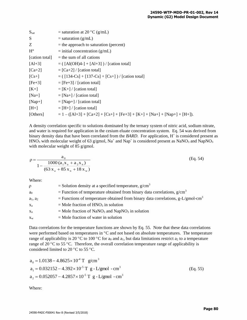
24590-WTP-MDD-PR-01-002, Rev 14 Dynamic (G2) Model Design Document
Page 80
24590-PADC-F00041 Rev 8 (Revised 3/5/2018)
Ssat = saturation at 20 C (g/mL)
S = saturation (g/mL)
Z = the approach to saturation (percent)
H° = initial concentration (g/mL)
[cation total] = the sum of all cations
[Al+3] = ( [Al(OH)4-] + [Al+3] ) / [cation total]
[Ca+2] = [Ca+2] / [cation total]
[Cs+] = ( [134-Cs] + [137-Cs] + [Cs+] ) / [cation total]
[Fe+3] = [Fe+3] / [cation total]
[K+] = [K+] / [cation total]
[Na+] = [Na+] / [cation total]
[Nap+] = [Nap+] / [cation total]
[H+] = [H+] / [cation total]
[Others] = 1 – ([Al+3] + [Ca+2] + [Cs+] + [Fe+3] + [K+] + [Na+] + [Nap+] + [H+]).
A density correlation specific to solutions dominated by the ternary system of nitric acid, sodium nitrate,
and water is required for application in the cesium eluate concentration system. Eq. 54 was derived from
binary density data that have been correlated from the BARD. For application, H+ is considered present as
HNO3 with molecular weight of 63 g/gmol, Na+ and Nap+ is considered present as NaNO3 and NapNO3
with molecular weight of 85 g/gmol.
) x18 x85 x(63
)xax(a 10001
aρ
wna
n2a1
0
(Eq. 54)
Where:
= Solution density at a specified temperature, g/cm3
a0 = Function of temperature obtained from binary data correlations, g/cm3
a1, a2 = Functions of temperature obtained from binary data correlations, g-L/gmol-cm3
xa = Mole fraction of HNO3 in solution
xn = Mole fraction of NaNO3 and NapNO3 in solution
xw = Mole fraction of water in solution
Data correlations for the temperature functions are shown by Eq. 55. Note that these data correlations
were performed based on temperatures in C and not based on absolute temperatures. The temperature
range of applicability is 20 C to 100 C for a0 and a1, but data limitations restrict a2 to a temperature
range of 20 C to 55 C. Therefore, the overall correlation temperature range of applicability is
considered limited to 20 C to 55 C.
35-
2
35-
1
3-4
0
cm-L/gmol-g T 104.28570.052057a
cm-L/gmol-g T 104.3920.032152a
g/cm T 104.86251.0138a
(Eq. 55)
Where:
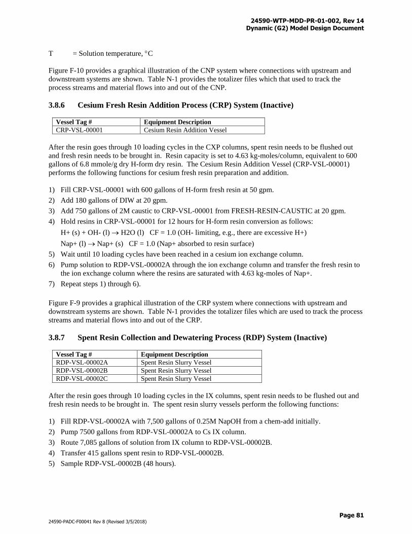
24590-WTP-MDD-PR-01-002, Rev 14 Dynamic (G2) Model Design Document
Page 81
24590-PADC-F00041 Rev 8 (Revised 3/5/2018)
T = Solution temperature, C
Figure F-10 provides a graphical illustration of the CNP system where connections with upstream and
downstream systems are shown. Table N-1 provides the totalizer files which that used to track the
process streams and material flows into and out of the CNP.
3.8.6 Cesium Fresh Resin Addition Process (CRP) System (Inactive)
Vessel Tag # Equipment Description
CRP-VSL-00001 Cesium Resin Addition Vessel
After the resin goes through 10 loading cycles in the CXP columns, spent resin needs to be flushed out
and fresh resin needs to be brought in. Resin capacity is set to 4.63 kg-moles/column, equivalent to 600
gallons of 6.8 mmole/g dry H-form dry resin. The Cesium Resin Addition Vessel (CRP-VSL-00001)
performs the following functions for cesium fresh resin preparation and addition.
1) Fill CRP-VSL-00001 with 600 gallons of H-form fresh resin at 50 gpm.
2) Add 180 gallons of DIW at 20 gpm.
3) Add 750 gallons of 2M caustic to CRP-VSL-00001 from FRESH-RESIN-CAUSTIC at 20 gpm.
4) Hold resins in CRP-VSL-00001 for 12 hours for H-form resin conversion as follows:
H+ (s) + OH- (l) H2O (l) CF = 1.0 (OH- limiting, e.g., there are excessive H+)
Nap+ (l) Nap+ (s) CF = 1.0 (Nap+ absorbed to resin surface)
5) Wait until 10 loading cycles have been reached in a cesium ion exchange column.
6) Pump solution to RDP-VSL-00002A through the ion exchange column and transfer the fresh resin to
the ion exchange column where the resins are saturated with 4.63 kg-moles of Nap+.
7) Repeat steps 1) through 6).
Figure F-9 provides a graphical illustration of the CRP system where connections with upstream and
downstream systems are shown. Table N-1 provides the totalizer files which are used to track the process
streams and material flows into and out of the CRP.
3.8.7 Spent Resin Collection and Dewatering Process (RDP) System (Inactive)
Vessel Tag # Equipment Description
RDP-VSL-00002A Spent Resin Slurry Vessel
RDP-VSL-00002B Spent Resin Slurry Vessel
RDP-VSL-00002C Spent Resin Slurry Vessel
After the resin goes through 10 loading cycles in the IX columns, spent resin needs to be flushed out and
fresh resin needs to be brought in. The spent resin slurry vessels perform the following functions:
1) Fill RDP-VSL-00002A with 7,500 gallons of 0.25M NapOH from a chem-add initially.
2) Pump 7500 gallons from RDP-VSL-00002A to Cs IX column.
3) Route 7,085 gallons of solution from IX column to RDP-VSL-00002B.
4) Transfer 415 gallons spent resin to RDP-VSL-00002B.
5) Sample RDP-VSL-00002B (48 hours).
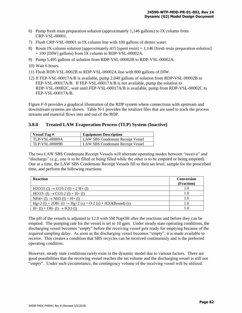
24590-WTP-MDD-PR-01-002, Rev 14 Dynamic (G2) Model Design Document
Page 82
24590-PADC-F00041 Rev 8 (Revised 3/5/2018)
6) Pump fresh resin preparation solution (approximately 1,146 gallons) to IX column from
CRP-VSL-00001.
7) Flush CRP-VSL-00001 to IX column line with 100 gallons of demin water.
8) Route IX column solution (approximately 415 [spent resin] + 1,146 [fresh resin preparation solution]
+ 100 [DIW] gallons) from IX column to RDP-VSL-00002A.
9) Pump 5,495 gallons of solution from RDP-VSL-00002B to RDP-VSL-00002A.
10) Wait 6 hours.
11) Flush RDP-VSL-0002B to RDP-VSL-00002A line with 800 gallons of DIW.
12) If FEP-VSL-00017A/B is available, pump 2,040 gallons of solution from RDP-VSL-00002B to
FEP-VSL-00017A/B. If FEP-VSL-00017A/B is not available, pump the solution to
RDP-VSL-00002C, wait until FEP-VSL-00017A/B is available, pump from RDP-VSL-00002C to
FEP-VSL-00017A/B.
Figure F-9 provides a graphical illustration of the RDP system where connections with upstream and
downstream systems are shown. Table N-1 provides the totalizer files that are used to track the process
streams and material flows into and out of the RDP.
3.8.8 Treated LAW Evaporation Process (TLP) System (Inactive)
Vessel Tag # Equipment Description
TLP-VSL-00009A LAW SBS Condensate Receipt Vessel
TLP-VSL-00009B LAW SBS Condensate Receipt Vessel
The two LAW SBS Condensate Receipt Vessels will alternate operating modes between “receive” and
“discharge” (e.g., one is to be filled or being filled while the other is to be emptied or being emptied).
One at a time, the LAW SBS Condensate Receipt Vessels fill to their set level, sample for the prescribed
time, and perform the following reactions:
Reaction Conversion
(Fraction)
H2CO3 (l) CO3-2 (l) + 2 H+ (l) 1.0
HCO3- (l) CO3-2 (l) + H+ (l) 1.0
NH4+ (l) NH3 (l) + H+ (l) 1.0
Hg+2 (l) + 2OH- (l) → Hg+2 (s) + O-2 (s) + H2O(Bound) (s) 1.0
H+ (l) + OH- (l) H2O (l) 1.0
The pH of the vessels is adjusted to 12.0 with 5M NapOH after the reactions and before they can be
emptied. The pumping rate for the vessel is set to 10 gpm. Under steady state operating conditions, the
discharging vessel becomes “empty” before the receiving vessel gets ready for emptying because of the
required sampling delay. As soon as the discharging vessel becomes “empty”, it is made available to
receive. This creates a condition that SBS recycles can be received continuously and is the preferred
operating condition.
However, steady state conditions rarely exist in the dynamic model due to various factors. There are
good possibilities that the receiving vessel reaches the set volume and the discharging vessel is still not
“empty”. Under such circumstance, the contingency volume of the receiving vessel will be utilized.
24590-WTP-MDD-PR-01-002, Rev 14 Dynamic (G2) Model Design Document
Page 83
24590-PADC-F00041 Rev 8 (Revised 3/5/2018)
In the case that the contingency volume is used up in the receiving vessel and the discharging vessel is
still not “empty” under abnormal operating conditions, the discharging vessel will be switched to
receiving mode and the receiving vessel will be allowed to discharge.
Vessel Tag # Equipment Description
TLP-SEP-00001 Treated LAW Evaporator
The Treated LAW Evaporator is modeled to receive feeds from TLP-VSL-00009A or TLP-VSL-00009B,
and/or CXP-VSL-00026A, CXP-VSL-00026B, CXP-VSL-00026C, defined as “feed-only”, “recycle-
only,” and “dual-pumping”. Feed-only is the operation when TLP-SEP-00001 receives only the treated
LAW feed from CXP-VSL-00026A, CXP-VSL-00026B, or CXP-VSL-00026C. Recycle-only is the
operation when TLP-SEP-00001 is fed with recycle from TLP-VSL-00009A or TLP-VSL-00009B.
Dual-pumping is the operation when TLP-SEP-00001 receives both feed and recycle concurrently. Pump
rates for the three operations are given below:
1) Feed-Only
TLP-VSL-00009A/B = 0 gpm
CXP-VSL-00026A/B/C = 34 gpm
2) Recycle-Only
TLP-VSL-00009A/B = 10 gpm
CXP-VSL-00026A/B/C = 0 gpm
3) Dual-Pumping
TLP-VSL-00009A/B = 10 gpm
CXP-VSL-00026A/B/C = 30 gpm
Dominant operations are feed-only and dual-pumping, while recycle-only can also happen at times when
HLW Facility backs up the UFP processes which stops the treated LAW production.
The target for evaporator concentrate is SpG = 1.33 and/or a wt% solids = 3.4%, whichever comes first.
Oxalate and phosphate tend to precipitate in the evaporator after boil-off. Solubility is applied
continuously at the flash evaporation temperature (50 oC) which may slightly alter the SpG and/or wt%
solids values of the TLP evaporator bottom product. The rate of the evaporator is limited by the boil-off
rate of 30 gpm – 2 gpm for the evaporator recycle spray to give a modeled boil-off rate of 28 gpm.
Evaporator concentrate pump capacity is 34 gpm. The offgas from TLP-SEP-00001 is routed through
TLP-DMST-00001. The splits for the evaporator are shown in Table D-10.
To minimize foaming, AFA is added to the evaporator when it starts receiving a new batch from a feed
tank. AFA will be replenished after that in 1-hour intervals to make up losses due to decomposition and
discharge. Target concentrations for PPG and PDMS are discussed in Section 3.7.17.
Vessel Tag # Equipment Description
TLP-DMST-00001 Treated LAW Evaporator Demister
The Treated LAW Evaporator Demister receives offgas from TLP-SEP-00001. The demister is also
modeled as a condenser. The offgas is condensed based on splits as shown in Table D-11. The
condensate is sent to TLP-VSL-00002. The offgas that was not condensed is sent to PVP-SCB-00002 in
the Pretreatment Vessel Vent System.
24590-WTP-MDD-PR-01-002, Rev 14 Dynamic (G2) Model Design Document
Page 84
24590-PADC-F00041 Rev 8 (Revised 3/5/2018)
Vessel Tag # Equipment Description
TLP-VSL-00002 Treated LAW Evaporator Condensate Vessel
The Treated LAW Evaporator Condensate Vessel receives condensate from the demister,
TLP-DMST-00001. Water, used to model condensate from the vacuum eductors, is also delivered from a
chem-add to TLP-VSL-00002 at a rate of 0.96 gpm whenever TLP-SEP-00001 is operating. As soon as
the vessel reaches its maximum volume, it empties to RLD-VSL-00006A. TLP-VSL-00002 is available
to receive condensate unless it is at maximum volume and RLD-VSL-00006A cannot accept feed.
Figure F-11 provides a graphical illustration of the TLP system where connections with upstream and
downstream systems are shown. Table N-1 provides the totalizer files that are used to track the process
streams and material flows into and out of the TLP.
3.8.9 Treated LAW Concentrate Storage Process (TCP) System (Inactive)
Vessel Tag # Equipment Description
TCP-VSL-00001 Treated LAW Concentrate Storage Vessel
The Treated LAW Concentrate Storage Vessel receives the bottoms from TLP-SEP-00001. The vessel
fills to its set level (75,000 gallons) and then makes itself available to deliver feed to LCP-VSL-00001
and LCP-VSL-00002. The Treated LAW Concentrate Storage Vessel can still receive feed while it is
transferring out to another vessel. If the volume of TCP-VSL-00001 is above 80,000 gallons, then
TLP-SEP-00001 is set to only process SBS condensate from TLP-VSL-00009A and TLP-VSL-00009B
until the volume drops below 80,000 gallons (recycle-only operation as discussed in Section 3.8.8).
A supplemental LAW vessel (SUPPLEMENTAL-LAW-TREATED) is included in the TCP system for
the option of modeling the additional capacity needed to process the treated LAW feed. Details of the
supplemental LAW vessel operating logic are discussed in Section 3.7.14.
Figure F-11 provides a graphical illustration of the TCP system where connections with upstream and
downstream systems are shown. Table N-1 provides the totalizer files that are used to track the process
streams and material flows into and out of the TCP.
3.8.10 Pretreatment Vessel Vent Process (PVP/PJV) Systems (Inactive)
Vessel Tag # Equipment Description
PVP-SCB-00002 Vessel Vent Caustic Scrubber
The Vessel Vent Caustic Scrubber receives offgas from FEP-DMST-00001 and TLP-DMST-00001. Air
from air purge and air bubbler are blended into the offgas to the Vessel Vent Caustic Scrubber. The
scrubber fills to its set volume with 0.01M NapOH that is delivered through a chem-add at a rate of
70 gpm. As the offgas is received in the scrubber, components are collected in the 0.01M NapOH
solution based on splits. The splits of the Vessel Vent Caustic Scrubber are shown in Table D-3. The
remaining gas is routed to PVP-SCB-00002. After 24 hours, the scrubber empties its contents at a rate of
50 gpm to PWD-VSL-00044. After emptying, it receives another batch of 0.01M NapOH and continues
to remove components.
Vessel Tag # Equipment Description
PVP-HEME-00001A PVP High Efficiency Mist Eliminator (HEME)
PVP-HEME-00001B PVP HEME
24590-WTP-MDD-PR-01-002, Rev 14 Dynamic (G2) Model Design Document
Page 85
24590-PADC-F00041 Rev 8 (Revised 3/5/2018)
Vessel Tag # Equipment Description
PVP-HEME-00001C PVP HEME
PVP-HEME-00001 is used to model the combined functions of PVP-HEME-00001A,
PVP-HEME-00001B, and PVP-HEME-00001C (see BARD for details). PVP-HEME-00001 receives
offgas from PVP-SCB-00002. H2O is constantly fed to PVP-HEME-00001 by a chem-add at a rate of
0.133 gpm. Components from the offgas feed are captured in the liquid phase based on splits. The splits
of the PVP HEME are shown in Table D-4. The remaining gas is passed on to the PVP-HEPA. The
liquid from PVP-HEME-00001 is transferred to PVP-VSL-00001.
Vessel Tag # Equipment Description
PVP-VSL-00001 Vessel Vent HEME Drain Collection Vessel
PVP-VSL-00001 constantly receives liquid from PVP-HEME-00001. This collection vessel fills to its set
level and then transfers its contents to PWD-VSL-00044. If PWD-VSL-00044 is not available to receive
material, then PVP-VSL-00001 can continue to fill to its maximum volume until PWD-VSL-00044
becomes available. If PVP-VSL-00001 reaches its maximum volume and still cannot empty, then the
Pretreatment Vessel Vent Process will shut down.
Vessel Tag # Equipment Description
PVP-HEPA High Efficiency Particular Air (HEPA) Filter
The PVP-HEPA receives offgas from PVP-HEME-00001. Liquid and solid components from the offgas
feed are captured at the 100 % level except for polychlorinated biphenyls (PCBs) (C12H4Cl6), which is
captured at the 98 % level, and acetonitrile (C2H3N), which escapes totally to the downstream equipment.
The gas is routed to the PVP-Thermal-Oxidizer.
Vessel Tag # Equipment Description
PVP-Thermal-Oxidizer PVP Thermal Oxidizer
The PVP Thermal Oxidizer receives offgas from PVP High Efficiency Particular Air Filter. Acetonitrile
and PCB are oxidized according to the following reactions. The gases are routed to the
PVP-Carbon-Absorber.
Reaction Conversion
(Fraction)
C2H3N (l) + 3.75 O2 (g) 2 CO2 (g) + 1.5 H2O (g) + NO2 (g) 0.757
C12H4Cl6 (l) + 11.5 O2 (g) + H2O (g) 12 CO2 (g) + 6 HCl (g) 0.95
Vessel Tag # Equipment Description
PVP-ABS-00001A PVP Carbon Absorber
PVP-ABS-00001B PVP Carbon Absorber
PVP-ABS-00001A and PVP-ABS-00001B are modeled as one unit-operation, the PVP Carbon Absorber.
The PVP Carbon Absorber receives offgas from PVP Thermal Oxidizer. Acetonitrile and PCB gases are
also captured at the 90 % level. Remaining gases are routed to the PVP Offgas Stack.
Vessel Tag # Equipment Description
PJV-VSL-00001 PJV Vessel Vent Demister
24590-WTP-MDD-PR-01-002, Rev 14 Dynamic (G2) Model Design Document
Page 86
24590-PADC-F00041 Rev 8 (Revised 3/5/2018)
PJV-VSL-00001 in the Pulse Jet Ventilation (PJV) system is used to model PJV-DMST-00002A,
PJV-DMST-00002B, and PJV-DMST-00002C. PJV-VSL-00001 receives gas from multiple sources of
air as part of the Pulse Jet Mixer (PJM) and Reverse Flow Diverter (RFD). Components from the gas
feed are captured by the demister based on splits. The splits of the PJV Vessel Vent Demister are shown
in Table D-8. Cumulated captures are sent to PWD-VSL-00043 and the remaining gases are routed to the
PJV HEPA.
Vessel Tag # Equipment Description
PJV-HEPA PJV HEPA Filter
The PJV HEPA receives offgas from PJV-VSL-00001. Liquid and solid components from the offgas
feed are captured at the 100 % level. The splits of the PJV HEPA Filter are shown in Table D-9. The gas
is passed out the PVP-Offgas-Stack.
Figure F-6 provides a graphical illustration of the PVP/PJV systems where connections with upstream
and downstream systems are shown. Table N-1 provides the totalizer files that are used to track the
process streams and material flows into and out of the PVP/PJV.
Dynamic air utilization modeling capabilities including the purge air, bubbler air, PJM air, and RFD air
are discussed in Appendix G.
3.8.11 Radioactive Liquid Waste Disposal (RLD) System (Partially Inactive)
Vessel Tag # Equipment Description
RLD-VSL-00017A Alkaline Effluent Vessel
RLD-VSL-00017B Alkaline Effluent Vessel
The Alkaline Effluent Vessels receive fresh resin preparation solution from the Cesium Resin Addition
Vessel (CRP-VSL-00001) and effluent from the Caustic Collection Vessel (LVP-TK-00001). When
RLD-VSL-00017A/B reaches its set level, it will stop receiving feed, sample for a prescribed time, and
then make itself available to empty to RLD-TK-00006B. The vessels are not allowed to collect at the
same time. One of the vessels must fill and begin to sample before the other is allowed to start receiving
feed.
Vessel Tag # Equipment Description
RLD-TK-00006A Process Condensate Vessel
RLD-TK-00006A receives feed from the Waste Feed Evaporator Condensate Vessel (FEP-VSL-00005)
and the Treated LAW Evaporator Condensate Vessel (TLP-VSL-00002). A portion of the process
condensate will be recycled to various Pretreatment systems for washing, dilution, and line flush
operations. Excessive process condensate will be sent to the ETF/LERF through RLD-TK-00006B.
When RLD-TK-00006A reaches above 200,000 gallons (upper set point), the vessel volume will be
pumped down to 110,000 gallons (lower set point) by discharging to RLD-TK-00006B. The inventory
between the heel and lower set point is reserved for the Pretreatment process condensate operations. It is
possible for concurrent transfers from RLD-TK-00006A to RLD-TK-00006B and to the process
condensate header because they are on separate pumping systems. The pump rate to RLD-TK-00006B is
100 gpm and the pump rate to the process condensate header is 250 gpm.
Vessel Tag # Equipment Description
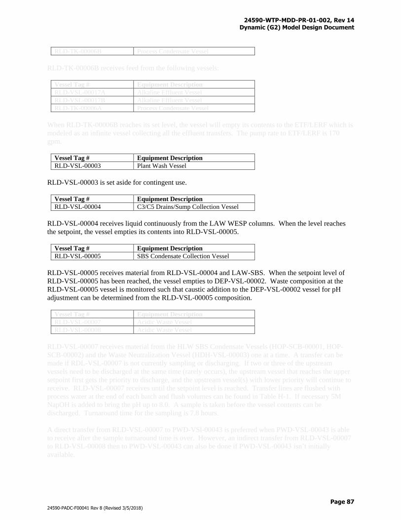
24590-WTP-MDD-PR-01-002, Rev 14 Dynamic (G2) Model Design Document
Page 87
24590-PADC-F00041 Rev 8 (Revised 3/5/2018)
RLD-TK-00006B Process Condensate Vessel
RLD-TK-00006B receives feed from the following vessels:
Vessel Tag # Equipment Description
RLD-VSL-00017A Alkaline Effluent Vessel
RLD-VSL-00017B Alkaline Effluent Vessel
RLD-TK-00006A Process Condensate Vessel
When RLD-TK-00006B reaches its set level, the vessel will empty its contents to the ETF/LERF which is
modeled as an infinite vessel collecting all the effluent transfers. The pump rate to ETF/LERF is 170
gpm.
Vessel Tag # Equipment Description
RLD-VSL-00003 Plant Wash Vessel
RLD-VSL-00003 is set aside for contingent use.
Vessel Tag # Equipment Description
RLD-VSL-00004 C3/C5 Drains/Sump Collection Vessel
RLD-VSL-00004 receives liquid continuously from the LAW WESP columns. When the level reaches
the setpoint, the vessel empties its contents into RLD-VSL-00005.
Vessel Tag # Equipment Description
RLD-VSL-00005 SBS Condensate Collection Vessel
RLD-VSL-00005 receives material from RLD-VSL-00004 and LAW-SBS. When the setpoint level of
RLD-VSL-00005 has been reached, the vessel empties to DEP-VSL-00002. Waste composition at the
RLD-VSL-00005 vessel is monitored such that caustic addition to the DEP-VSL-00002 vessel for pH
adjustment can be determined from the RLD-VSL-00005 composition.
Vessel Tag # Equipment Description
RLD-VSL-00007 Acidic Waste Vessel
RLD-VSL-00008 Acidic Waste Vessel
RLD-VSL-00007 receives material from the HLW SBS Condensate Vessels (HOP-SCB-00001, HOP-
SCB-00002) and the Waste Neutralization Vessel (HDH-VSL-00003) one at a time. A transfer can be
made if RDL-VSL-00007 is not currently sampling or discharging. If two or three of the upstream
vessels need to be discharged at the same time (rarely occurs), the upstream vessel that reaches the upper
setpoint first gets the priority to discharge, and the upstream vessel(s) with lower priority will continue to
receive. RLD-VSL-00007 receives until the setpoint level is reached. Transfer lines are flushed with
process water at the end of each batch and flush volumes can be found in Table H-1. If necessary 5M
NapOH is added to bring the pH up to 8.0. A sample is taken before the vessel contents can be
discharged. Turnaround time for the sampling is 7.8 hours.
A direct transfer from RLD-VSL-00007 to PWD-VSl-00043 is preferred when PWD-VSL-00043 is able
to receive after the sample turnaround time is over. However, an indirect transfer from RLD-VSL-00007
to RLD-VSL-00008 then to PWD-VSL-00043 can also be done if PWD-VSL-00043 isn’t initially
available.
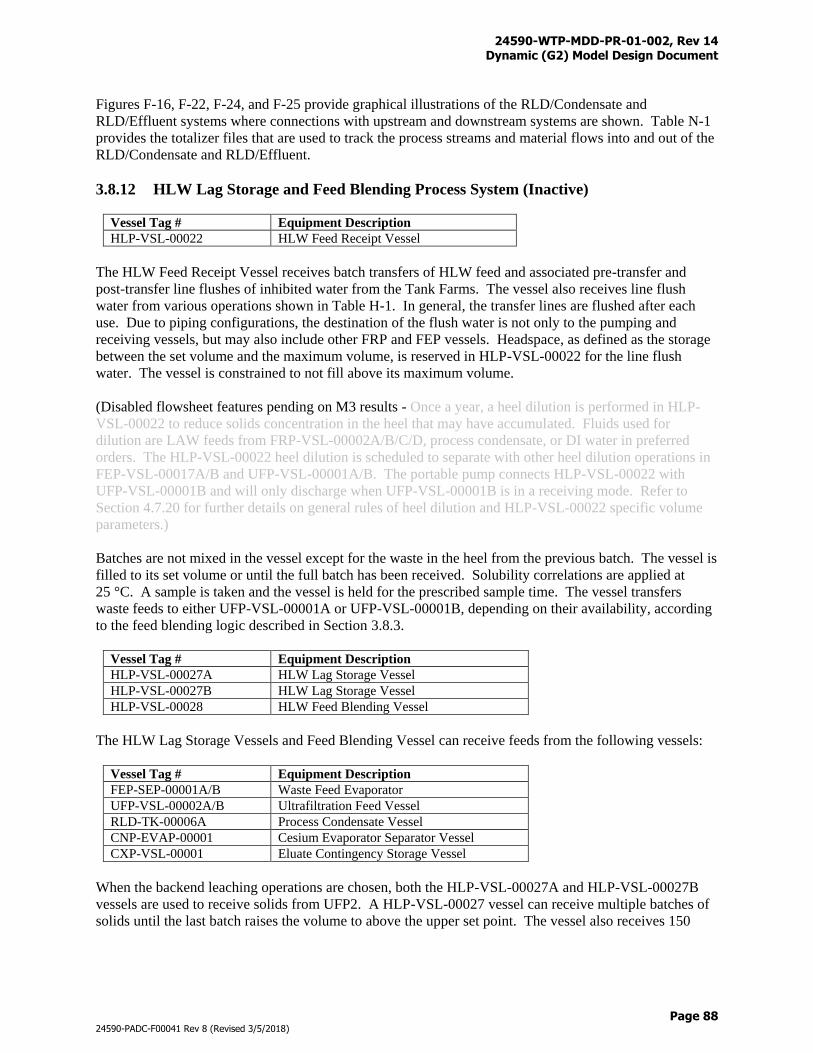
24590-WTP-MDD-PR-01-002, Rev 14 Dynamic (G2) Model Design Document
Page 88
24590-PADC-F00041 Rev 8 (Revised 3/5/2018)
Figures F-16, F-22, F-24, and F-25 provide graphical illustrations of the RLD/Condensate and
RLD/Effluent systems where connections with upstream and downstream systems are shown. Table N-1
provides the totalizer files that are used to track the process streams and material flows into and out of the
RLD/Condensate and RLD/Effluent.
3.8.12 HLW Lag Storage and Feed Blending Process System (Inactive)
Vessel Tag # Equipment Description
HLP-VSL-00022 HLW Feed Receipt Vessel
The HLW Feed Receipt Vessel receives batch transfers of HLW feed and associated pre-transfer and
post-transfer line flushes of inhibited water from the Tank Farms. The vessel also receives line flush
water from various operations shown in Table H-1. In general, the transfer lines are flushed after each
use. Due to piping configurations, the destination of the flush water is not only to the pumping and
receiving vessels, but may also include other FRP and FEP vessels. Headspace, as defined as the storage
between the set volume and the maximum volume, is reserved in HLP-VSL-00022 for the line flush
water. The vessel is constrained to not fill above its maximum volume.
(Disabled flowsheet features pending on M3 results - Once a year, a heel dilution is performed in HLP-
VSL-00022 to reduce solids concentration in the heel that may have accumulated. Fluids used for
dilution are LAW feeds from FRP-VSL-00002A/B/C/D, process condensate, or DI water in preferred
orders. The HLP-VSL-00022 heel dilution is scheduled to separate with other heel dilution operations in
FEP-VSL-00017A/B and UFP-VSL-00001A/B. The portable pump connects HLP-VSL-00022 with
UFP-VSL-00001B and will only discharge when UFP-VSL-00001B is in a receiving mode. Refer to
Section 4.7.20 for further details on general rules of heel dilution and HLP-VSL-00022 specific volume
parameters.)
Batches are not mixed in the vessel except for the waste in the heel from the previous batch. The vessel is
filled to its set volume or until the full batch has been received. Solubility correlations are applied at
25 °C. A sample is taken and the vessel is held for the prescribed sample time. The vessel transfers
waste feeds to either UFP-VSL-00001A or UFP-VSL-00001B, depending on their availability, according
to the feed blending logic described in Section 3.8.3.
Vessel Tag # Equipment Description
HLP-VSL-00027A HLW Lag Storage Vessel
HLP-VSL-00027B HLW Lag Storage Vessel
HLP-VSL-00028 HLW Feed Blending Vessel
The HLW Lag Storage Vessels and Feed Blending Vessel can receive feeds from the following vessels:
Vessel Tag # Equipment Description
FEP-SEP-00001A/B Waste Feed Evaporator
UFP-VSL-00002A/B Ultrafiltration Feed Vessel
RLD-TK-00006A Process Condensate Vessel
CNP-EVAP-00001 Cesium Evaporator Separator Vessel
CXP-VSL-00001 Eluate Contingency Storage Vessel
When the backend leaching operations are chosen, both the HLP-VSL-00027A and HLP-VSL-00027B
vessels are used to receive solids from UFP2. A HLP-VSL-00027 vessel can receive multiple batches of
solids until the last batch raises the volume to above the upper set point. The vessel also receives 150
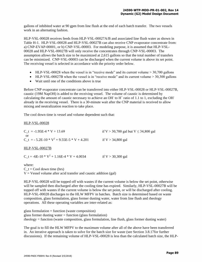
24590-WTP-MDD-PR-01-002, Rev 14 Dynamic (G2) Model Design Document
Page 89
24590-PADC-F00041 Rev 8 (Revised 3/5/2018)
gallons of inhibited water at 90 gpm from line flush at the end of each batch transfer. The two vessels
work in an alternating fashion.
HLP-VSL-00028 receives feeds from HLP-VSL-00027A/B and associated line flush water as shown in
Table H-1. HLP-VSL-00028 and HLP-VSL-00027B can also receive CNP evaporator concentrate from:
a) CNP-EVAP-00001, or b) CNP-VSL-00003. For modeling purpose, it is assumed that HLP-VSL-
00028 and HLP-VSL-00027B will only receive the concentrates through CNP-VSL-00003. The
assumption allows the batch size to be maximized at 2,615 gallons so that the total number of transfers
can be minimized. CNP-VSL-00003 can be discharged when the current volume is above its set point.
The receiving vessel is selected in accordance with the priority order below.
HLP-VSL-00028 when the vessel is in “receive mode” and its current volume > 30,700 gallons
HLP-VSL-00027B when the vessel is in “receive mode” and its current volume > 30,300 gallons
Wait until one of the conditions above is true
Before CNP evaporator concentrate can be transferred into either HLP-VSL-00028 or HLP-VSL-00027B,
caustic (19M NapOH) is added to the receiving vessel. The volume of caustic is determined by
calculating the amount of caustic necessary to achieve an OH- to H+ ratio of 1.1 to 1, excluding the OH-
already in the receiving vessel. There is a 30-minute wait after the CNP material is received to allow
mixing and neutralization reaction to take place.
The cool down time is vessel and volume dependent such that:
HLP-VSL-00028
C_t = -1.95E-4 * V + 13.69 if V > 30,700 gal but V ≤ 34,800 gal
or
C_t = - 5.2E-10 * V2 + 9.55E-5 * V + 4.201 if V > 34,800 gal
HLP-VSL-00027B
C_t = -6E-10 * V2 + 1.16E-4 * V + 4.0034 if V > 30,300 gal
where:
C_t = Cool down time (hrs)
V = Vessel volume after acid transfer and caustic addition (gal)
HLP-VSL-00028 will be topped off with wastes if the current volume is below the set point, otherwise
will be sampled then discharged after the cooling time has expired. Similarly, HLP-VSL-00027B will be
topped off with wastes if the current volume is below the set point, or will be discharged after cooling.
HLP-VSL-00028 discharges to the HLW MFPV in batches. Batch size is determined based on waste
composition, glass formulation, glass former dusting water, water from line flush and rheology
operations. All these operating variables are inter-related as:
glass formulation = function (waste composition)
glass former dusting water = function (glass formulation)
rheology = function (waste composition, glass formulation, line flush, glass former dusting water)
The goal is to fill the HLW MFPV to the maximum volume after all of the above have been transferred
in. An iterative approach is taken to solve for the batch size for waste (see Section 3.8.17for further
discussions). If the remaining volume of HLP-VSL-00028 is less than the calculated batch size, the HLP-
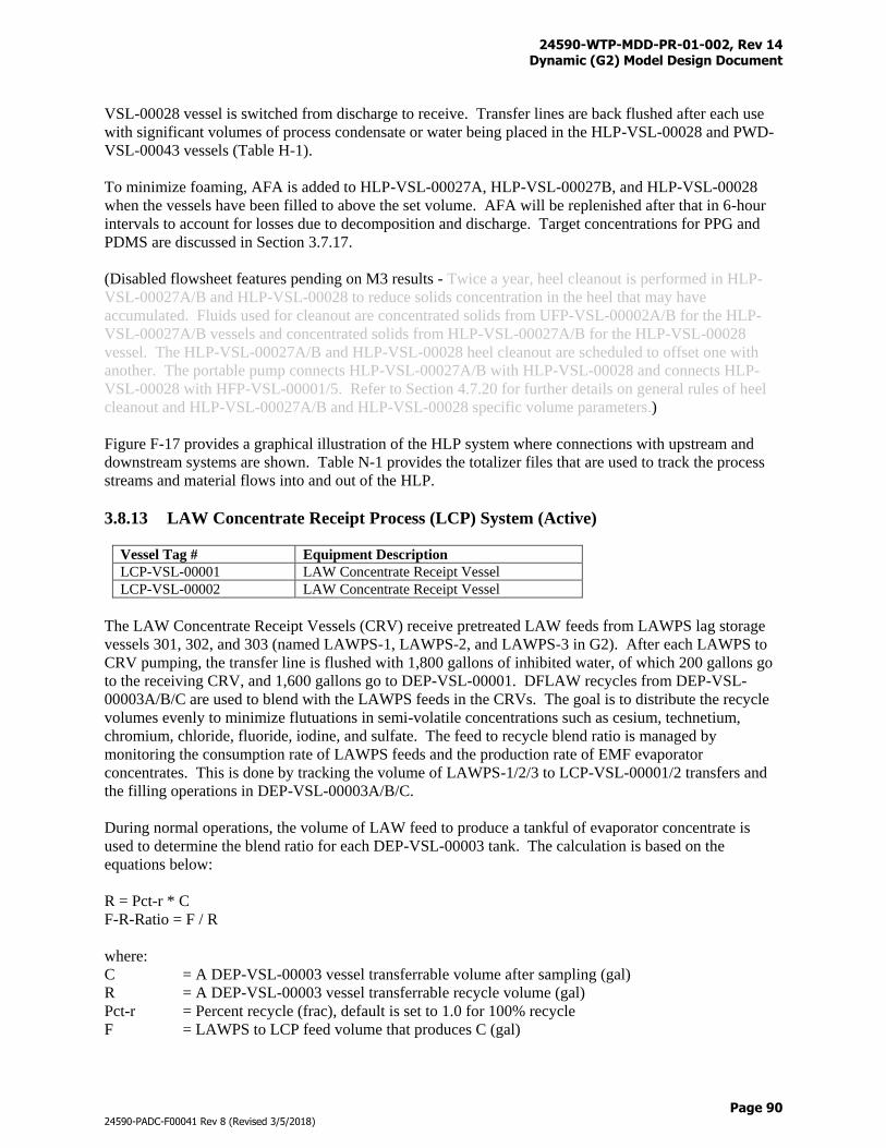
24590-WTP-MDD-PR-01-002, Rev 14 Dynamic (G2) Model Design Document
Page 90
24590-PADC-F00041 Rev 8 (Revised 3/5/2018)
VSL-00028 vessel is switched from discharge to receive. Transfer lines are back flushed after each use
with significant volumes of process condensate or water being placed in the HLP-VSL-00028 and PWD-
VSL-00043 vessels (Table H-1).
To minimize foaming, AFA is added to HLP-VSL-00027A, HLP-VSL-00027B, and HLP-VSL-00028
when the vessels have been filled to above the set volume. AFA will be replenished after that in 6-hour
intervals to account for losses due to decomposition and discharge. Target concentrations for PPG and
PDMS are discussed in Section 3.7.17.
(Disabled flowsheet features pending on M3 results - Twice a year, heel cleanout is performed in HLP-
VSL-00027A/B and HLP-VSL-00028 to reduce solids concentration in the heel that may have
accumulated. Fluids used for cleanout are concentrated solids from UFP-VSL-00002A/B for the HLP-
VSL-00027A/B vessels and concentrated solids from HLP-VSL-00027A/B for the HLP-VSL-00028
vessel. The HLP-VSL-00027A/B and HLP-VSL-00028 heel cleanout are scheduled to offset one with
another. The portable pump connects HLP-VSL-00027A/B with HLP-VSL-00028 and connects HLP-
VSL-00028 with HFP-VSL-00001/5. Refer to Section 4.7.20 for further details on general rules of heel
cleanout and HLP-VSL-00027A/B and HLP-VSL-00028 specific volume parameters.)
Figure F-17 provides a graphical illustration of the HLP system where connections with upstream and
downstream systems are shown. Table N-1 provides the totalizer files that are used to track the process
streams and material flows into and out of the HLP.
3.8.13 LAW Concentrate Receipt Process (LCP) System (Active)
Vessel Tag # Equipment Description
LCP-VSL-00001 LAW Concentrate Receipt Vessel
LCP-VSL-00002 LAW Concentrate Receipt Vessel
The LAW Concentrate Receipt Vessels (CRV) receive pretreated LAW feeds from LAWPS lag storage
vessels 301, 302, and 303 (named LAWPS-1, LAWPS-2, and LAWPS-3 in G2). After each LAWPS to
CRV pumping, the transfer line is flushed with 1,800 gallons of inhibited water, of which 200 gallons go
to the receiving CRV, and 1,600 gallons go to DEP-VSL-00001. DFLAW recycles from DEP-VSL-
00003A/B/C are used to blend with the LAWPS feeds in the CRVs. The goal is to distribute the recycle
volumes evenly to minimize flutuations in semi-volatile concentrations such as cesium, technetium,
chromium, chloride, fluoride, iodine, and sulfate. The feed to recycle blend ratio is managed by
monitoring the consumption rate of LAWPS feeds and the production rate of EMF evaporator
concentrates. This is done by tracking the volume of LAWPS-1/2/3 to LCP-VSL-00001/2 transfers and
the filling operations in DEP-VSL-00003A/B/C.
During normal operations, the volume of LAW feed to produce a tankful of evaporator concentrate is
used to determine the blend ratio for each DEP-VSL-00003 tank. The calculation is based on the
equations below:
R = Pct-r * C
F-R-Ratio = F / R
where:
C = A DEP-VSL-00003 vessel transferrable volume after sampling (gal)
R = A DEP-VSL-00003 vessel transferrable recycle volume (gal)
Pct-r = Percent recycle (frac), default is set to 1.0 for 100% recycle
F = LAWPS to LCP feed volume that produces C (gal)
24590-WTP-MDD-PR-01-002, Rev 14 Dynamic (G2) Model Design Document
Page 91
24590-PADC-F00041 Rev 8 (Revised 3/5/2018)
F-R-Ratio = Feed to recycle volume ratio for LCP feed blending (unitless)
Blending operation is modeled by placing recycle and feed in sequence to the receiving LCP vessel in
accordance with the F-R-Ratio, followed by line flush water.
Confirmation samples are taken at the LCP vessels where glass formulations are determined. Sample
hold time is set to 12 hours. No uncertainties are assumed for the LCP waste compositions.
The LCP-VSL-00001/2 vessels alternate with each other in operation. When a LAW CRV has reached its
maximum level, the vessel samples for a prescribed time, then becomes available to empty to either
LFP-VSL-00001 or LFP-VSL-00003 depending on their availability. Based on the CRV sample
compositions, batch size and glass former recipes will be determined. Batch size determines the number
of transfers that can be made to the LAW MFPVs. Glass former recipes are determined using the
Immobilized Low-Activity Waste (ILAW) glass formulation model shown in Figure 14 through Figure 16
(refer to the BARD for further details). The batch size and glass former recipe decisions ensure that
1) LFP-VSL-00001 or LFP-VSL-00003 will not overflow
2) Rheology water target is met (≥ 36 wt % water)
3) LAW glass quality specifications are met
4) Melter corrosion due to high lithium contents in the feed is prevented
5) Halide, chromium, and phosphate will not hinder melting process
The number of requests for LAW glass former recipes are equal to the number of batches to the LAW
MFPVs. Glass formers can be prepared as soon as recipes exist in the LAW recipe queue given that the
GFR is available. It shall be noted that GFR priorities are given to HLW glass formers, e.g., HLW
recipes will be processed first if requests exist in both LAW recipe queue and HLW recipe queue (refer to
Section 3.8.22 for GFR operatons). Due to the fact that LAW glass former recipies are known for future
LAW CRV to LAW MFPV batches, LAW glass formers can be prepared in parallel to, or even ahead of,
the CRV to MFPV waste transfers.
Transfer lines are flushed with process water after each use and both the CRV and MFPV will receive
some flush water (Table H-1). Partial batch transfer to the MFPV is prohibited, meaning that the CRV
will switch to filling mode if the remaining volume in the vessel is less than a full batch. After the pre-
determined number of batches have been transferred out, the CRV makes itself available to fill.
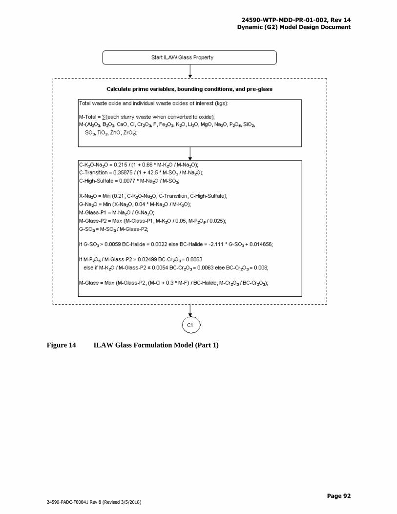
24590-WTP-MDD-PR-01-002, Rev 14 Dynamic (G2) Model Design Document
Page 92
24590-PADC-F00041 Rev 8 (Revised 3/5/2018)
Figure 14 ILAW Glass Formulation Model (Part 1)
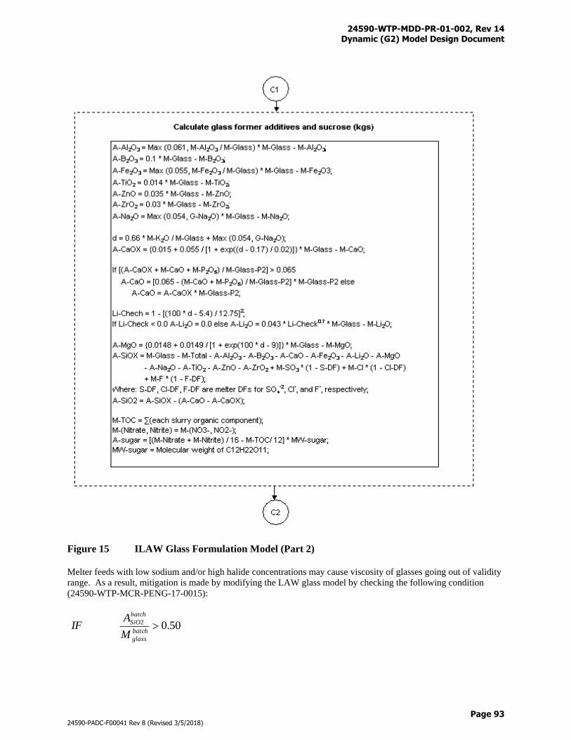
24590-WTP-MDD-PR-01-002, Rev 14 Dynamic (G2) Model Design Document
Page 93
24590-PADC-F00041 Rev 8 (Revised 3/5/2018)
Figure 15 ILAW Glass Formulation Model (Part 2)
Melter feeds with low sodium and/or high halide concentrations may cause viscosity of glasses going out of validity
range. As a result, mitigation is made by modifying the LAW glass model by checking the following condition
(24590-WTP-MCR-PENG-17-0015):
50.02 batch
glass
batch
SiO
M
AIF
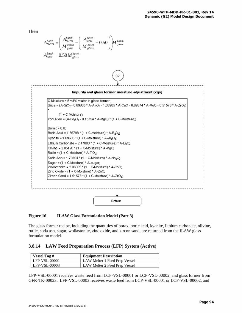
24590-WTP-MDD-PR-01-002, Rev 14 Dynamic (G2) Model Design Document
Page 94
24590-PADC-F00041 Rev 8 (Revised 3/5/2018)
Then
batch
glassbatch
glass
batch
SiO
batch
glass
batch
ONabatch
ONa MM
A
M
AA
50.022
2
batch
glass
batch
SiO MA 50.02
Figure 16 ILAW Glass Formulation Model (Part 3)
The glass former recipe, including the quantities of borax, boric acid, kyanite, lithium carbonate, olivine,
rutile, soda ash, sugar, wollastonite, zinc oxide, and zircon sand, are returned from the ILAW glass
formulation model.
3.8.14 LAW Feed Preparation Process (LFP) System (Active)
Vessel Tag # Equipment Description
LFP-VSL-00001 LAW Melter 1 Feed Prep Vessel
LFP-VSL-00003 LAW Melter 2 Feed Prep Vessel
LFP-VSL-00001 receives waste feed from LCP-VSL-00001 or LCP-VSL-00002, and glass former from
GFR-TK-00023. LFP-VSL-00003 receives waste feed from LCP-VSL-00001 or LCP-VSL-00002, and
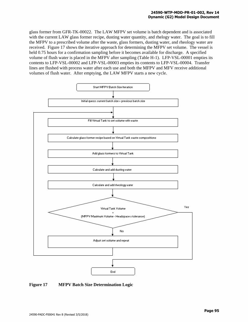
24590-WTP-MDD-PR-01-002, Rev 14 Dynamic (G2) Model Design Document
Page 95
24590-PADC-F00041 Rev 8 (Revised 3/5/2018)
glass former from GFR-TK-00022. The LAW MFPV set volume is batch dependent and is associated
with the current LAW glass former recipe, dusting water quantity, and rhelogy water. The goal is to fill
the MFPV to a prescribed volume after the waste, glass formers, dusting water, and rheology water are
received. Figure 17 shows the iterative approach for determining the MFPV set volume. The vessel is
held 0.75 hours for a confirmation sampling before it becomes available for discharge. A specified
volume of flush water is placed in the MFPV after sampling (Table H-1). LFP-VSL-00001 empties its
contents to LFP-VSL-00002 and LFP-VSL-00003 empties its contents to LFP-VSL-00004. Transfer
lines are flushed with process water after each use and both the MFPV and MFV receive additional
volumes of flush water. After emptying, the LAW MFPV starts a new cycle.
Figure 17 MFPV Batch Size Determination Logic
24590-WTP-MDD-PR-01-002, Rev 14 Dynamic (G2) Model Design Document
Page 96
24590-PADC-F00041 Rev 8 (Revised 3/5/2018)
Vessel Tag # Equipment Description
LFP-VSL-00002 LAW Melter 1 Feed Vessel
LFP-VSL-00004 LAW Melter 2 Feed Vessel
The LAW MFVs receive feed from the corresponding LAW MFPVs. LFP-VSL-00002 transfers material
only to LMP-MLTR-00001 and LFP-VSL-00004 transfers material only to LMP-MLTR-00002. Transfer
rate is variable depending on the contents of the waste. A more diluted feed will have a higher transfer
rate so that the target glass production rate can be maintained. When a LAW MFV reaches its lower
setpoint it becomes available to receive feed again while continuing to empty to its minimum volume.
This prevents the LAW melter from becoming idle. The only time that an LAW MFV will stop pumping
to the melter is when there is no feed available from the LAW MFPV and the LAW MFV is at its
minimum volume.
After the MFV receives a batch transfer from the MFPV and after the MFV completes a batch discharge,
process water is flushed into the MFV and associated melter (Table H-1). Process water is also flushed
into the receiving melter once every 4 hours between the cycles.
Figure F-12 provides a graphical illustration of the LCP/LFP systems where connections with upstream
and downstream systems are shown. Table N-1 provides the totalizer files that are used to track the
process streams and material flows into and out of the LCP/LFP.
3.8.15 LAW Melter Process (LMP) System (Active)
Vessel Tag # Equipment Description
LMP-MLTR-00001 LAW Melter 1
LMP-MLTR-00002 LAW Melter 2
With treated LAW feeds at low waste oxide concentrations from time to time, melter production rate
becomes a concern. Power diverted to boiling extra water may decrease the efficiency of the melters. A
set of equations was derived in Variable LAW Melt Rate (24590-WTP-MCR-PE-13-0024) that calculates
the melter production rate as a function glass forming oxides, solid concentrations, and water
concentrations in the MFV. The MCR also provides equations to determine if the melters have enough
power capability to actually produce glass calculated by the concentration based rate equations. If power
capabilities are exceeded, the MCR provides logic to trim back the production rate. Implementation of
the variable LAW melt rate is presented as follows.
1) After a LAW MFV is filled, calculate melt rate of the vessel contents, M-rate (MTG/day)
016.0*031.010_ 25 XXrateM (Eq. 56)
where x is the oxide concentration (g/L)
2) Calculate maximum melter production rate based on power supply (per melter)
wSw
rwPF
E
fAday
95.3171)1
*14.86_ (Eq. 57)
Where:
F_day = Maximum melter glass production rate (MTG/day)
PA = Power available for heating and to convert feed to glass and off gas (kW)
24590-WTP-MDD-PR-01-002, Rev 14 Dynamic (G2) Model Design Document
Page 97
24590-PADC-F00041 Rev 8 (Revised 3/5/2018)
w = Weight fraction of water in feed (unitless)
rf = Mass ratio of feed solids to glass (unitless)
SE = Specific energy requirement for ILAW (kJ/kg)
Further details can be found in Attachment A of 24590-WTP-MCR-PE-13-0024.
3) Check rate (R) against current operation limits (COL)
R = min (M-rate, F-day, COL) WTP LAW Melters (entire mission)
= min (M-rate, F-day, 9) S-LAW Melter (Oct 1, 2022 to Jan. 1, 2025)
= min (M-rate, F-day, 90) S-LAW Melter (from Jan 1, 2025)
LAW Melters (LMP-MLTR-00001 and LMP-MLTR-00002) are used to transform the LAW into glass.
Liquid and solid wastes, oxide glass formers and impurities, lineflush water, air, and film cooler water
rinse are delivered to the melters. The inflow of waste and glass formers depends on the availability of
feed; however, the inflow of air is continuous once started. The air stream is made up of: 1) air inleakage,
2) bubbler air, 3) purge air, 4) control air, and 5) cooling air, while the water stream represents the film
cooler water rinse. The combined air flowrate and the associated temperature and pressure are shown in
Table B-15. The film cooler water rinse flowrate is shown in the same table. The air provides the source
of oxygen for the melter reactions.
When feed enters the melter, a split is applied to the non-gas components including the liquid and solid
wastes, and oxide glass formers and associated mineral impurities. The liquid split values are applied to
the liquid components that come into the melter while the solid split values are applied to the combined
solids of solid wastes, oxide glass formers, and impurities. The predefined split values are shown in
Table D-12. Exceptions are applied to the following components of which melter reactions or a
combination of melter reactions and splits are more appropriate:
Components Liquid%
to SBS
Solid%
to SBS
Descriptions
129-I 0.000 0.000 129-I (l,s) → 129-I (g) CF = 0.4167, remaining go to glass
3-H 100.000 100.000 Follows water, 100% go to offgas
C12H4Cl6 0.000 0.000 C12H4Cl6 (l,s) + 11.5 O2 (g) + H2O (l) → 12 CO2 (g) + 6 HCl (g) CF =
1.0
C2H3N 0.000 0.000 C2H3N (l,s) + 3.75 O2 (g) → 2 CO2 (g) + 1.5 H2O (g) + NO2 (g) CF =
1.0
C2O4-2 0.000 0.000 C2O4-2 (l,s) → 2 CO2 (g) CF = 1.0
CHO2- 0.000 0.000 CHO2- (l,s) + 0.25 O2 (g) → CO2 (g) + 0.5 H2O (g) CF = 1.0
Cl- 0.000 0.000 2 Cl- (l,s) + 2 Na+ (l,s) + H2O (l) → Na2O (o) + 2 HCl (g) CF = 0.5025,
remaining go to glass
CN- 1.852 1.852 2 CN- (l,s) + 2 O2 (g) → 2 CO2 (g) + N2 (g), CF = 1.0,
partially split to offgas, remaining 100% destroyed
CO3-2 0.000 0.000 CO3-2 (l,s) → CO2 (g) + 0.5 O2 (g) CF = 1.0
F- 0.000 0.000 2 F- (l,s) + 2 Na+ (l,s) + H2O (l) → Na2O (o) + 2 HF (g) CF = 0.5319,
remaining go to glass
H+ 0.000 0.000 H+ (l,s) + OH(BOUND) (l,s) → H2O (g) CF = 1.0
H2CO3 0.000 0.000 H2CO3 (l,s) → CO2 (g) + H2O (g) CF = 1.0
H2O 0.000 0.000 H2O (l,s) → H2O (g) CF = 1.0
H2O2 0.000 0.000 2 H2O2 (l,s) → 2 H2O (g) + O2 (g) CF = 1.0
HCO3- 0.000 0.000 2 HCO3- (l,s) → 2 CO2 (g) + H2O (g) + 0.5 O2 (g) CF = 1.0
24590-WTP-MDD-PR-01-002, Rev 14 Dynamic (G2) Model Design Document
Page 98
24590-PADC-F00041 Rev 8 (Revised 3/5/2018)
Components Liquid%
to SBS
Solid%
to SBS
Descriptions
NH3 0.000 0.000 2 NH3 (l,s) + 3 O2 (g) → NO (g) + NO2 (g) + 3 H2O (g) CF = 1.0
NH4+ 0.000 0.000 2 NH4+ (l,s) + 3.5 O2 (g) → NO (g) + NO2 (g) + 4 H2O (g) CF = 1.0
NO2- 0.000 0.000 See Eq. 59 in the following discussions
NO3- 0.000 0.000 See Eq. 58 in the following discussions
O-2 0.000 0.000 2 O-2 (l,s) → O2 (g) CF = 1.0
OH(BOUND) 0.000 0.000 2 OH(Bound) (l,s) → H2O (g) + 0.5 O2 (g) CF = 1.0
OH- 0.000 0.000 2 OH- (l,s) → H2O (g) + 0.5 O2 (g) CF = 1.0
SO4-2 0.000 0.000 SO4-2 (l,s) → SO2 (g) + O2 (g), CF is dynamically determined,
remaining is oxidized and go to glass
TOC 0.000 0.000 TOC (l,s) + O2 (g) → CO2 (g) CF = 1.0
Nitrate and nitrite decomposition reactions are shown in Eq. 58 and Eq. 59 where the stoichiometric
coefficients are dependent upon the variable multiplier M. These reactions provide the means for
approximating the test data which found the SBS solution to be near neutral (pH = 6.5 to 7.5) due to
variations of ammonia gas production rate.
r11NO3- (l,s) + r12H2O (l) → p11N2 (g) + p12NO (g) + p13NO2 (g) + p14NH3 (g) +
(0.25+p15)O2 (g) Eq. (58)
r21NO2- (l,s) + r22H2O (l) → p21N2 (g) + p22NO (g) + p23NO2 (g) + p24NH3 (g) +
(0.25+p25)O2 (g) Eq. (59)
where the stoichiometric coefficients are given as follows:
r11: 1 r21: 1
r12: 0.03623M r22: 0.03623M
p11: 0.2546-0.0121(M-1) p21: 0.2546-0.0121(M-1)
p12: 0.4239 p22: 0.4239
p13: 0.04277 p23: 0.04277
p14: 0.024154M p24: 0.024154M
p15: 1.01339+0.0181(M-1) p25: 0.5134+0.0181(M-1)
M is a multiplier that can be used to determine the ammonia production rate in the next time step. As the
pH values of the SBSs are very sensitive to the ammonia gas production in the melters, variable M values
are applied based on the current pH value in the SBS. A lookup table is provided as follows:
Current pH M
pH <= 3.0 1.05
3.0 < pH <= 4.0 1.01
4.0 < pH <= 5.0 1.005
5.0 < pH <= 6.0 1.001
6.0 < pH <= 6.5 1.0001
6.5 < pH <= 7.0 1.00001
7.0 < pH <= 7.5 0.99999
7.5 < pH <= 8.0 0.9999
8.0 < pH <= 9.0 0.999
9.0 < pH <= 10.0 0.995
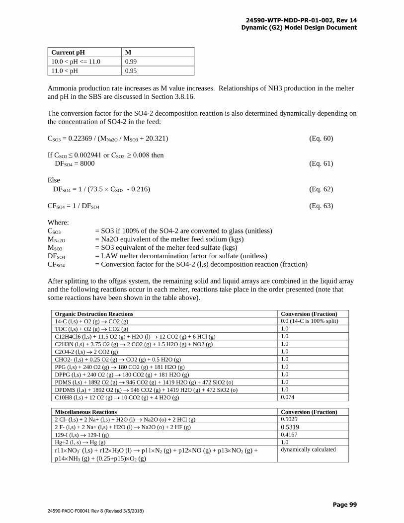
24590-WTP-MDD-PR-01-002, Rev 14 Dynamic (G2) Model Design Document
Page 99
24590-PADC-F00041 Rev 8 (Revised 3/5/2018)
Current pH M
10.0 < pH <= 11.0 0.99
11.0 < pH 0.95
Ammonia production rate increases as M value increases. Relationships of NH3 production in the melter
and pH in the SBS are discussed in Section 3.8.16.
The conversion factor for the SO4-2 decomposition reaction is also determined dynamically depending on
the concentration of SO4-2 in the feed:
CSO3 = 0.22369 / (MNa2O / MSO3 + 20.321) (Eq. 60)
If CSO3 ≤ 0.002941 or CSO3 ≥ 0.008 then
DFSO4 = 8000 (Eq. 61)
Else
DFSO4 = 1 / (73.5 CSO3 - 0.216) (Eq. 62)
CFSO4 = 1 / DFSO4 (Eq. 63)
Where:
CSO3 = SO3 if 100% of the SO4-2 are converted to glass (unitless)
MNa2O = Na2O equivalent of the melter feed sodium (kgs)
MSO3 = SO3 equivalent of the melter feed sulfate (kgs)
DFSO4 = LAW melter decontamination factor for sulfate (unitless)
CFSO4 = Conversion factor for the SO4-2 (l,s) decomposition reaction (fraction)
After splitting to the offgas system, the remaining solid and liquid arrays are combined in the liquid array
and the following reactions occur in each melter, reactions take place in the order presented (note that
some reactions have been shown in the table above).
Organic Destruction Reactions Conversion (Fraction)
14-C (l,s) + O2 (g) CO2 (g) 0.0 (14-C is 100% split)
TOC (l,s) + O2 (g) CO2 (g) 1.0
C12H4Cl6 (l,s) + 11.5 O2 (g) + H2O (l) 12 CO2 (g) + 6 HCl (g) 1.0
C2H3N (l,s) + 3.75 O2 (g) 2 CO2 (g) + 1.5 H2O (g) + NO2 (g) 1.0
C2O4-2 (l,s) 2 CO2 (g) 1.0
CHO2- (l,s) + 0.25 O2 (g) CO2 (g) + 0.5 H2O (g) 1.0
PPG (l,s) + 240 O2 (g) 180 CO2 (g) + 181 H2O (g) 1.0
DPPG (l,s) + 240 O2 (g) 180 CO2 (g) + 181 H2O (g) 1.0
PDMS (l,s) + 1892 O2 (g) 946 CO2 (g) + 1419 H2O (g) + 472 SiO2 (o) 1.0
DPDMS (l,s) + 1892 O2 (g) 946 CO2 (g) + 1419 H2O (g) + 472 SiO2 (o) 1.0
C10H8 (l,s) + 12 O2 (g) 10 CO2 (g) + 4 H2O (g) 0.074
Miscellaneous Reactions Conversion (Fraction)
2 Cl- (l,s) + 2 Na+ (l,s) + H2O (l) Na2O (o) + 2 HCl (g) 0.5025
2 F- (l,s) + 2 Na+ (l,s) + H2O (l) Na2O (o) + 2 HF (g) 0.5319
129-I (l,s) 129-I (g) 0.4167
Hg+2 (l, s) → Hg (g) 1.0
r11NO3- (l,s) + r12H2O (l) → p11N2 (g) + p12NO (g) + p13NO2 (g) +
p14NH3 (g) + (0.25+p15)O2 (g)
dynamically calculated
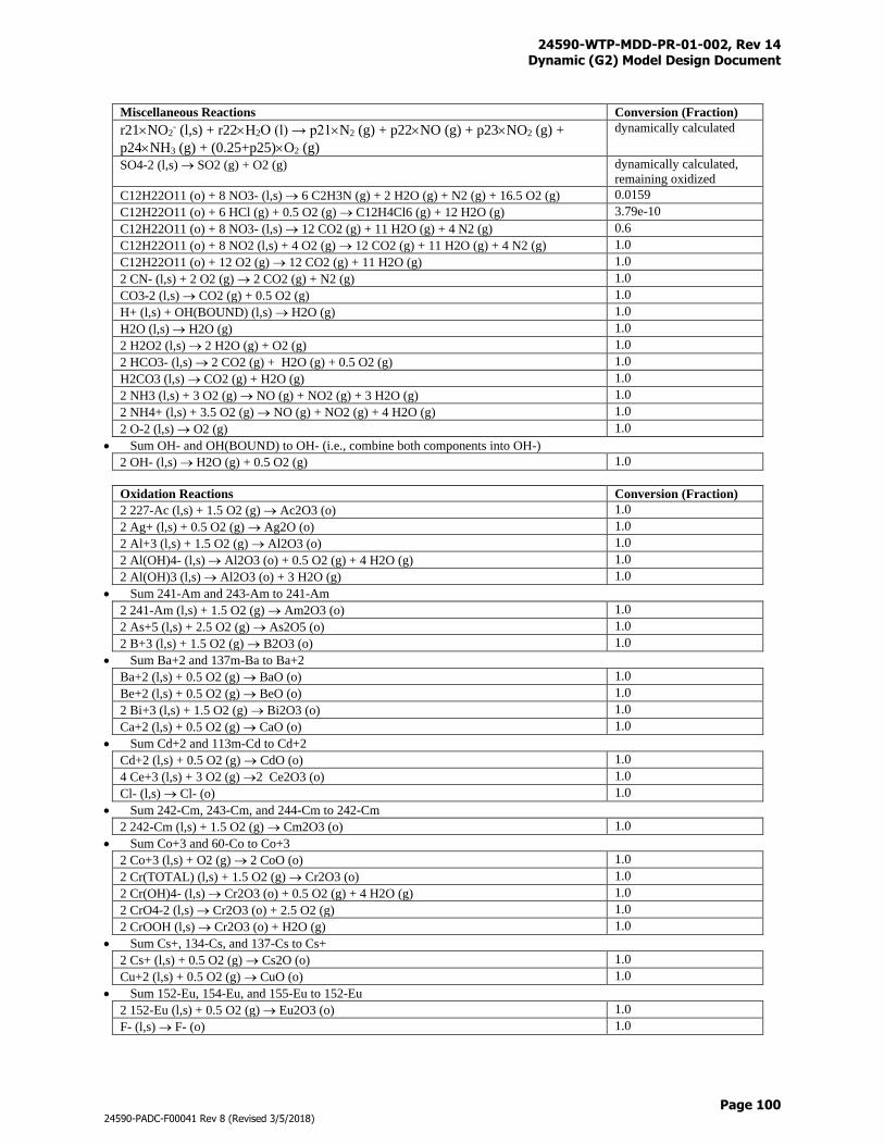
24590-WTP-MDD-PR-01-002, Rev 14 Dynamic (G2) Model Design Document
Page 100
24590-PADC-F00041 Rev 8 (Revised 3/5/2018)
Miscellaneous Reactions Conversion (Fraction)
r21NO2- (l,s) + r22H2O (l) → p21N2 (g) + p22NO (g) + p23NO2 (g) +
p24NH3 (g) + (0.25+p25)O2 (g)
dynamically calculated
SO4-2 (l,s) SO2 (g) + O2 (g) dynamically calculated,
remaining oxidized
C12H22O11 (o) + 8 NO3- (l,s) 6 C2H3N (g) + 2 H2O (g) + N2 (g) + 16.5 O2 (g) 0.0159
C12H22O11 (o) + 6 HCl (g) + 0.5 O2 (g) C12H4Cl6 (g) + 12 H2O (g) 3.79e-10
C12H22O11 (o) + 8 NO3- (l,s) 12 CO2 (g) + 11 H2O (g) + 4 N2 (g) 0.6
C12H22O11 (o) + 8 NO2 (l,s) + 4 O2 (g) 12 CO2 (g) + 11 H2O (g) + 4 N2 (g) 1.0
C12H22O11 (o) + 12 O2 (g) 12 CO2 (g) + 11 H2O (g) 1.0
2 CN- (l,s) + 2 O2 (g) 2 CO2 (g) + N2 (g) 1.0
CO3-2 (l,s) CO2 (g) + 0.5 O2 (g) 1.0
H+ (l,s) + OH(BOUND) (l,s) H2O (g) 1.0
H2O (l,s) H2O (g) 1.0
2 H2O2 (l,s) 2 H2O (g) + O2 (g) 1.0
2 HCO3- (l,s) 2 CO2 (g) + H2O (g) + 0.5 O2 (g) 1.0
H2CO3 (l,s) CO2 (g) + H2O (g) 1.0
2 NH3 (l,s) + 3 O2 (g) NO (g) + NO2 (g) + 3 H2O (g) 1.0
2 NH4+ (l,s) + 3.5 O2 (g) NO (g) + NO2 (g) + 4 H2O (g) 1.0
2 O-2 (l,s) O2 (g) 1.0
Sum OH- and OH(BOUND) to OH- (i.e., combine both components into OH-)
2 OH- (l,s) H2O (g) + 0.5 O2 (g) 1.0
Oxidation Reactions Conversion (Fraction)
2 227-Ac (l,s) + 1.5 O2 (g) Ac2O3 (o) 1.0
2 Ag+ (l,s) + 0.5 O2 (g) Ag2O (o) 1.0
2 Al+3 (l,s) + 1.5 O2 (g) Al2O3 (o) 1.0
2 Al(OH)4- (l,s) Al2O3 (o) + 0.5 O2 (g) + 4 H2O (g) 1.0
2 Al(OH)3 (l,s) Al2O3 (o) + 3 H2O (g) 1.0
Sum 241-Am and 243-Am to 241-Am
2 241-Am (l,s) + 1.5 O2 (g) Am2O3 (o) 1.0
2 As+5 (l,s) + 2.5 O2 (g) As2O5 (o) 1.0
2 B+3 (l,s) + 1.5 O2 (g) B2O3 (o) 1.0
Sum Ba+2 and 137m-Ba to Ba+2
Ba+2 (l,s) + 0.5 O2 (g) BaO (o) 1.0
Be+2 (l,s) + 0.5 O2 (g) BeO (o) 1.0
2 Bi+3 (l,s) + 1.5 O2 (g) Bi2O3 (o) 1.0
Ca+2 (l,s) + 0.5 O2 (g) CaO (o) 1.0
Sum Cd+2 and 113m-Cd to Cd+2
Cd+2 (l,s) + 0.5 O2 (g) CdO (o) 1.0
4 Ce+3 (l,s) + 3 O2 (g) 2 Ce2O3 (o) 1.0
Cl- (l,s) Cl- (o) 1.0
Sum 242-Cm, 243-Cm, and 244-Cm to 242-Cm
2 242-Cm (l,s) + 1.5 O2 (g) Cm2O3 (o) 1.0
Sum Co+3 and 60-Co to Co+3
2 Co+3 (l,s) + O2 (g) 2 CoO (o) 1.0
2 Cr(TOTAL) (l,s) + 1.5 O2 (g) Cr2O3 (o) 1.0
2 Cr(OH)4- (l,s) Cr2O3 (o) + 0.5 O2 (g) + 4 H2O (g) 1.0
2 CrO4-2 (l,s) Cr2O3 (o) + 2.5 O2 (g) 1.0
2 CrOOH (l,s) Cr2O3 (o) + H2O (g) 1.0
Sum Cs+, 134-Cs, and 137-Cs to Cs+
2 Cs+ (l,s) + 0.5 O2 (g) Cs2O (o) 1.0
Cu+2 (l,s) + 0.5 O2 (g) CuO (o) 1.0
Sum 152-Eu, 154-Eu, and 155-Eu to 152-Eu
2 152-Eu (l,s) + 0.5 O2 (g) Eu2O3 (o) 1.0
F- (l,s) F- (o) 1.0
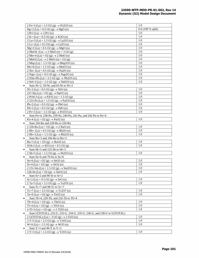
24590-WTP-MDD-PR-01-002, Rev 14 Dynamic (G2) Model Design Document
Page 101
24590-PADC-F00041 Rev 8 (Revised 3/5/2018)
2 Fe+3 (l,s) + 1.5 O2 (g) Fe2O3 (o) 1.0
Hg+2 (l,s) + 0.5 O2 (g) HgO (o) 0.0 (100 % split)
129-I (l,s) 129-I (o) 1.0
2 K+ (l,s) + 0.5 O2 (g) K2O (o) 1.0
2 La+3 (l,s) + 1.5 O2 (g) La2O3 (o) 1.0
2 Li+ (l,s) + 0.5 O2 (g) Li2O (o) 1.0
Mg+2 (l,s) + 0.5 O2 (g) MgO (o) 1.0
2 MnO4- (l,s) 2 MnO (o) + 3 O2 (g) 1.0
2 Mn+4 (l,s) + O2 (g) 2 MnO (o) 1.0
2 MnO2 (l,s) 2 MnO (o) + O2 (g) 1.0
2 Mnp (l,s) + 1.5 O2 (g) Mnp2O3 (o) 1.0
Mo+6 (l,s) + 1.5 O2 (g) MoO3 (o) 1.0
2 Na+ (l,s) + 0.5 O2 (g) Na2O (o) 1.0
2 Nap+ (l,s) + 0.5 O2 (g) Nap2O (o) 1.0
2 93m-Nb (l,s) + 2.5 O2 (g) Nb2O5 (o) 1.0
2 Nd+3 (l,s) + 1.5 O2 (g) Nd2O3 (o) 1.0
Sum Ni+2, 59-Ni, and 63-Ni to Ni+2
Ni+2 (l,s) + 0.5 O2 (g) NiO (o) 1.0
237-Np (l,s) + O2 (g) NpO2 (o) 1.0
2 PO4-3 (l,s) P2O5 (o) + 1.5 O2 (g) 1.0
2 231-Pa (l,s) + 1.5 O2 (g) Pa2O3 (o) 1.0
Pb+2 (l,s) + 0.5 O2 (g) PbO (o) 1.0
Pd+2 (l,s) + 0.5 O2 (g) PdO (o) 1.0
2 Pr+3 (l,s) + 1.5 O2 (g) Pr2O3 (o) 1.0
Sum Pu+4, 238-Pu, 239-Pu, 240-Pu, 241-Pu, and 242-Pu to Pu+4
Pu+4 (l,s) + O2 (g) PuO2 (o) 1.0
Sum 226-Ra and 228-Ra to 226-Ra
2 226-Ra (l,s) + O2 (g) 2 RaO (o) 1.0
2 Rb+ (l,s) + 0.5 O2 (g) Rb2O (o) 1.0
2 Rh+3 (l,s) + 1.5 O2 (g) Rh2O3 (o) 1.0
Sum Ru+3 and 106-Ru to Ru+3
Ru+3 (l,s) + O2 (g) RuO2 (o) 1.0
SO4-2 (l,s) SO3 (o) + 0.5 O2 (g) 1.0
Sum Sb+5 and 125-Sb to Sb+5
2 Sb+5 (l,s) + 1.5 O2 (g) Sb2O3 (o) 1.0
Sum Se+6 and 79-Se to Se+6
Se+6 (l,s) + O2 (g) SeO2 (o) 1.0
Si+4 (l,s) + O2 (g) SiO2 (o) 1.0
2 151-Sm (l,s) + 1.5 O2 (g) Sm2O3 (o) 1.0
126-Sn (l,s) + O2 (g) SnO2 (o) 1.0
Sum Sr+2 and 90-Sr to Sr+2
Sr+2 (l,s) + 0.5 O2 (g) SrO (o) 1.0
2 Ta+5 (l,s) + 2.5 O2 (g) Ta2O5 (o) 1.0
Sum Tc+7 and 99-Tc to Tc+7
Tc+7 (l,s) + 3.5 O2 (g) Tc2O7 (o) 1.0
Te+6 (l,s) + O2 (g) TeO2 (o) 1.0
Sum Th+4, 229-Th, and 232-Th to Th+4
Th+4 (l,s) + O2 (g) ThO2 (o) 1.0
Ti+4 (l,s) + O2 (g) TiO2 (o) 1.0
4 Tl+3 (l,s) + O2 (g) 2 Tl2O (o) 1.0
Sum U(TOTAL), 232-U, 233-U, 234-U, 235-U, 236-U, and 238-U to U(TOTAL)
2 U(TOTAL) (l,s) + 3 O2 (g) 2 UO3 (o) 1.0
2 V+5 (l,s) + 2.5 O2 (g) V2O5 (o) 1.0
W+6 (l,s) + 1.5 O2 (g) WO3 (o) 1.0
Sum Y+3 and 90-Y to Y+3
2 Y+3 (l,s) + 1.5 O2 (g) Y2O3 (o) 1.0
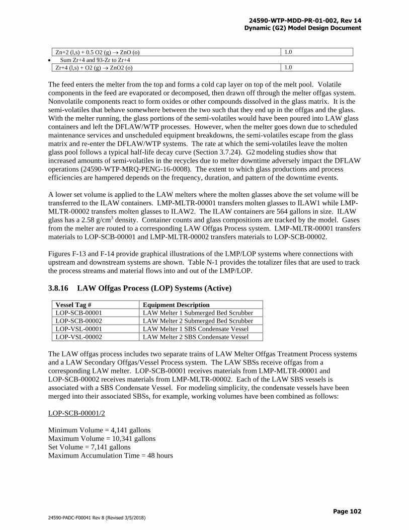
24590-WTP-MDD-PR-01-002, Rev 14 Dynamic (G2) Model Design Document
Page 102
24590-PADC-F00041 Rev 8 (Revised 3/5/2018)
Zn+2 (l,s) + 0.5 O2 (g) ZnO (o) 1.0
Sum Zr+4 and 93-Zr to Zr+4
Zr+4 (l,s) + O2 (g) ZnO2 (o) 1.0
The feed enters the melter from the top and forms a cold cap layer on top of the melt pool. Volatile
components in the feed are evaporated or decomposed, then drawn off through the melter offgas system.
Nonvolatile components react to form oxides or other compounds dissolved in the glass matrix. It is the
semi-volatiles that behave somewhere between the two such that they end up in the offgas and the glass.
With the melter running, the glass portions of the semi-volatiles would have been poured into LAW glass
containers and left the DFLAW/WTP processes. However, when the melter goes down due to scheduled
maintenance services and unscheduled equipment breakdowns, the semi-volatiles escape from the glass
matrix and re-enter the DFLAW/WTP systems. The rate at which the semi-volatiles leave the molten
glass pool follows a typical half-life decay curve (Section 3.7.24). G2 modeling studies show that
increased amounts of semi-volatiles in the recycles due to melter downtime adversely impact the DFLAW
operations (24590-WTP-MRQ-PENG-16-0008). The extent to which glass productions and process
efficiencies are hampered depends on the frequency, duration, and pattern of the downtime events.
A lower set volume is applied to the LAW melters where the molten glasses above the set volume will be
transferred to the ILAW containers. LMP-MLTR-00001 transfers molten glasses to ILAW1 while LMP-
MLTR-00002 transfers molten glasses to ILAW2. The ILAW containers are 564 gallons in size. ILAW
glass has a 2.58 g/cm3 density. Container counts and glass compositions are tracked by the model. Gases
from the melter are routed to a corresponding LAW Offgas Process system. LMP-MLTR-00001 transfers
materials to LOP-SCB-00001 and LMP-MLTR-00002 transfers materials to LOP-SCB-00002.
Figures F-13 and F-14 provide graphical illustrations of the LMP/LOP systems where connections with
upstream and downstream systems are shown. Table N-1 provides the totalizer files that are used to track
the process streams and material flows into and out of the LMP/LOP.
3.8.16 LAW Offgas Process (LOP) Systems (Active)
Vessel Tag # Equipment Description
LOP-SCB-00001 LAW Melter 1 Submerged Bed Scrubber
LOP-SCB-00002 LAW Melter 2 Submerged Bed Scrubber
LOP-VSL-00001 LAW Melter 1 SBS Condensate Vessel
LOP-VSL-00002 LAW Melter 2 SBS Condensate Vessel
The LAW offgas process includes two separate trains of LAW Melter Offgas Treatment Process systems
and a LAW Secondary Offgas/Vessel Process system. The LAW SBSs receive offgas from a
corresponding LAW melter. LOP-SCB-00001 receives materials from LMP-MLTR-00001 and
LOP-SCB-00002 receives materials from LMP-MLTR-00002. Each of the LAW SBS vessels is
associated with a SBS Condensate Vessel. For modeling simplicity, the condensate vessels have been
merged into their associated SBSs, for example, working volumes have been combined as follows:
LOP-SCB-00001/2
Minimum Volume = 4,141 gallons
Maximum Volume = 10,341 gallons
Set Volume = 7,141 gallons
Maximum Accumulation Time = 48 hours
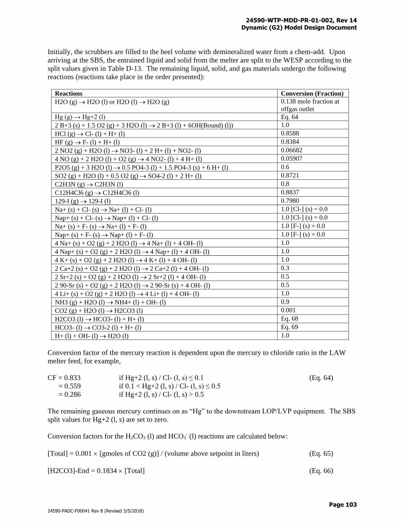
24590-WTP-MDD-PR-01-002, Rev 14 Dynamic (G2) Model Design Document
Page 103
24590-PADC-F00041 Rev 8 (Revised 3/5/2018)
Initially, the scrubbers are filled to the heel volume with demineralized water from a chem-add. Upon
arriving at the SBS, the entrained liquid and solid from the melter are split to the WESP according to the
split values given in Table D-13. The remaining liquid, solid, and gas materials undergo the following
reactions (reactions take place in the order presented):
Reactions Conversion (Fraction)
H2O (g) H2O (l) or H2O (l) H2O (g) 0.138 mole fraction at
offgas outlet
Hg (g) → Hg+2 (l) Eq. 64
2 B+3 (s) + 1.5 O2 (g) + 3 H2O (l) 2 B+3 (l) + 6OH(Bound) (l)) 1.0
HCl (g) Cl- (l) + H+ (l) 0.8588
HF (g) F- (l) + H+ (l) 0.8384
2 NO2 (g) + H2O (l) NO3- (l) + 2 H+ (l) + NO2- (l) 0.06682
4 NO (g) + 2 H2O (l) + O2 (g) 4 NO2- (l) + 4 H+ (l) 0.05907
P2O5 (g) + 3 H2O (l) 0.5 PO4-3 (l) + 1.5 PO4-3 (s) + 6 H+ (l) 0.6
SO2 (g) + H2O (l) + 0.5 O2 (g) SO4-2 (l) + 2 H+ (l) 0.8721
C2H3N (g) C2H3N (l) 0.8
C12H4Cl6 (g) C12H4Cl6 (l) 0.8837
129-I (g) 129-I (l) 0.7980
Na+ (s) + Cl- (s) Na+ (l) + Cl- (l) 1.0 [Cl-] (s) = 0.0
Nap+ (s) + Cl- (s) Nap+ (l) + Cl- (l) 1.0 [Cl-] (s) = 0.0
Na+ (s) + F- (s) Na+ (l) + F- (l) 1.0 [F-] (s) = 0.0
Nap+ (s) + F- (s) Nap+ (l) + F- (l) 1.0 [F-] (s) = 0.0
4 Na+ (s) + O2 (g) + 2 H2O (l) 4 Na+ (l) + 4 OH- (l) 1.0
4 Nap+ (s) + O2 (g) + 2 H2O (l) 4 Nap+ (l) + 4 OH- (l) 1.0
4 K+ (s) + O2 (g) + 2 H2O (l) 4 K+ (l) + 4 OH- (l) 1.0
2 Ca+2 (s) + O2 (g) + 2 H2O (l) 2 Ca+2 (l) + 4 OH- (l) 0.3
2 Sr+2 (s) + O2 (g) + 2 H2O (l) 2 Sr+2 (l) + 4 OH- (l) 0.5
2 90-Sr (s) + O2 (g) + 2 H2O (l) 2 90-Sr (s) + 4 OH- (l) 0.5
4 Li+ (s) + O2 (g) + 2 H2O (l) 4 Li+ (l) + 4 OH- (l) 1.0
NH3 (g) + H2O (l) NH4+ (l) + OH- (l) 0.9
CO2 (g) + H2O (l) H2CO3 (l) 0.001
H2CO3 (l) HCO3- (l) + H+ (l) Eq. 68
HCO3- (l) CO3-2 (l) + H+ (l) Eq. 69
H+ (l) + OH- (l) H2O (l) 1.0
Conversion factor of the mercury reaction is dependent upon the mercury to chloride ratio in the LAW
melter feed, for example,
CF = 0.833 if Hg+2 (l, s) / Cl- (l, s) ≤ 0.1 (Eq. 64)
= 0.559 if 0.1 < Hg+2 (l, s) / Cl- (l, s) ≤ 0.5
= 0.286 if Hg+2 (l, s) / Cl- (l, s) > 0.5
The remaining gaseous mercury continues on as “Hg” to the downstream LOP/LVP equipment. The SBS
split values for Hg+2 (l, s) are set to zero.
Conversion factors for the H2CO3 (l) and HCO3- (l) reactions are calculated below:
[Total] = 0.001 [gmoles of CO2 (g)] / (volume above setpoint in liters) (Eq. 65)
[H2CO3]-End = 0.1834 [Total] (Eq. 66)
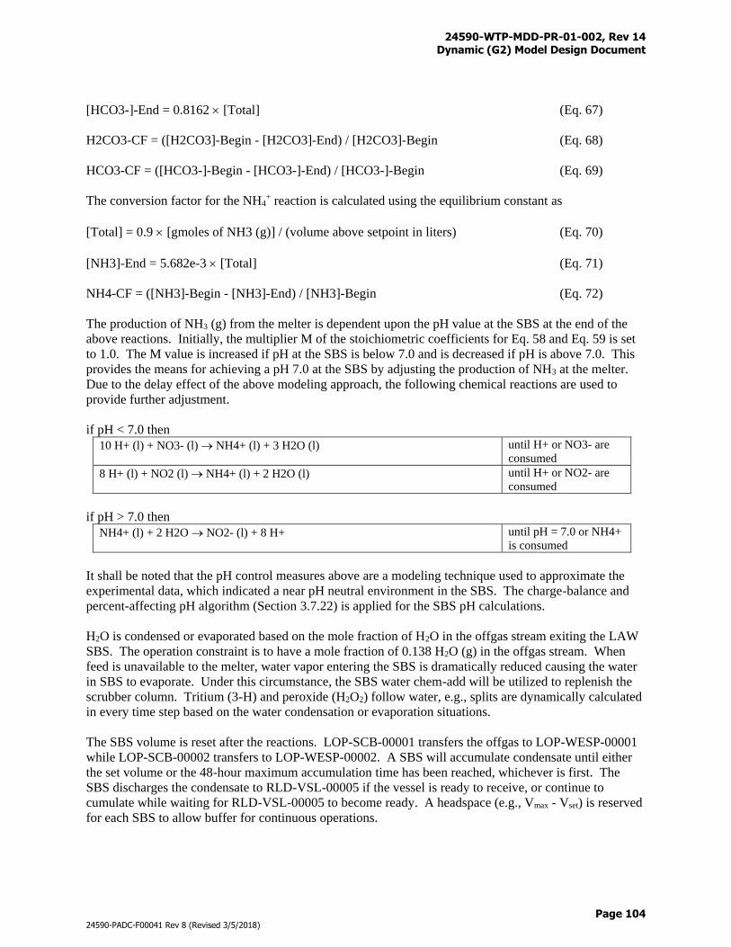
24590-WTP-MDD-PR-01-002, Rev 14 Dynamic (G2) Model Design Document
Page 104
24590-PADC-F00041 Rev 8 (Revised 3/5/2018)
[HCO3-]-End = 0.8162 [Total] (Eq. 67)
H2CO3-CF = ([H2CO3]-Begin - [H2CO3]-End) / [H2CO3]-Begin (Eq. 68)
HCO3-CF = ([HCO3-]-Begin - [HCO3-]-End) / [HCO3-]-Begin (Eq. 69)
The conversion factor for the NH4+ reaction is calculated using the equilibrium constant as
[Total] = 0.9 [gmoles of NH3 (g)] / (volume above setpoint in liters) (Eq. 70)
[NH3]-End = 5.682e-3 [Total] (Eq. 71)
NH4-CF = ([NH3]-Begin - [NH3]-End) / [NH3]-Begin (Eq. 72)
The production of NH3 (g) from the melter is dependent upon the pH value at the SBS at the end of the
above reactions. Initially, the multiplier M of the stoichiometric coefficients for Eq. 58 and Eq. 59 is set
to 1.0. The M value is increased if pH at the SBS is below 7.0 and is decreased if pH is above 7.0. This
provides the means for achieving a pH 7.0 at the SBS by adjusting the production of NH3 at the melter.
Due to the delay effect of the above modeling approach, the following chemical reactions are used to
provide further adjustment.
if pH < 7.0 then
10 H+ (l) + NO3- (l) NH4+ (l) + 3 H2O (l) until H+ or NO3- are
consumed
8 H+ (l) + NO2 (l) NH4+ (l) + 2 H2O (l) until H+ or NO2- are
consumed
if pH > 7.0 then
NH4+ (l) + 2 H2O NO2- (l) + 8 H+ until pH = 7.0 or NH4+
is consumed
It shall be noted that the pH control measures above are a modeling technique used to approximate the
experimental data, which indicated a near pH neutral environment in the SBS. The charge-balance and
percent-affecting pH algorithm (Section 3.7.22) is applied for the SBS pH calculations.
H2O is condensed or evaporated based on the mole fraction of H2O in the offgas stream exiting the LAW
SBS. The operation constraint is to have a mole fraction of 0.138 H2O (g) in the offgas stream. When
feed is unavailable to the melter, water vapor entering the SBS is dramatically reduced causing the water
in SBS to evaporate. Under this circumstance, the SBS water chem-add will be utilized to replenish the
scrubber column. Tritium (3-H) and peroxide (H2O2) follow water, e.g., splits are dynamically calculated
in every time step based on the water condensation or evaporation situations.
The SBS volume is reset after the reactions. LOP-SCB-00001 transfers the offgas to LOP-WESP-00001
while LOP-SCB-00002 transfers to LOP-WESP-00002. A SBS will accumulate condensate until either
the set volume or the 48-hour maximum accumulation time has been reached, whichever is first. The
SBS discharges the condensate to RLD-VSL-00005 if the vessel is ready to receive, or continue to
cumulate while waiting for RLD-VSL-00005 to become ready. A headspace (e.g., Vmax - Vset) is reserved
for each SBS to allow buffer for continuous operations.
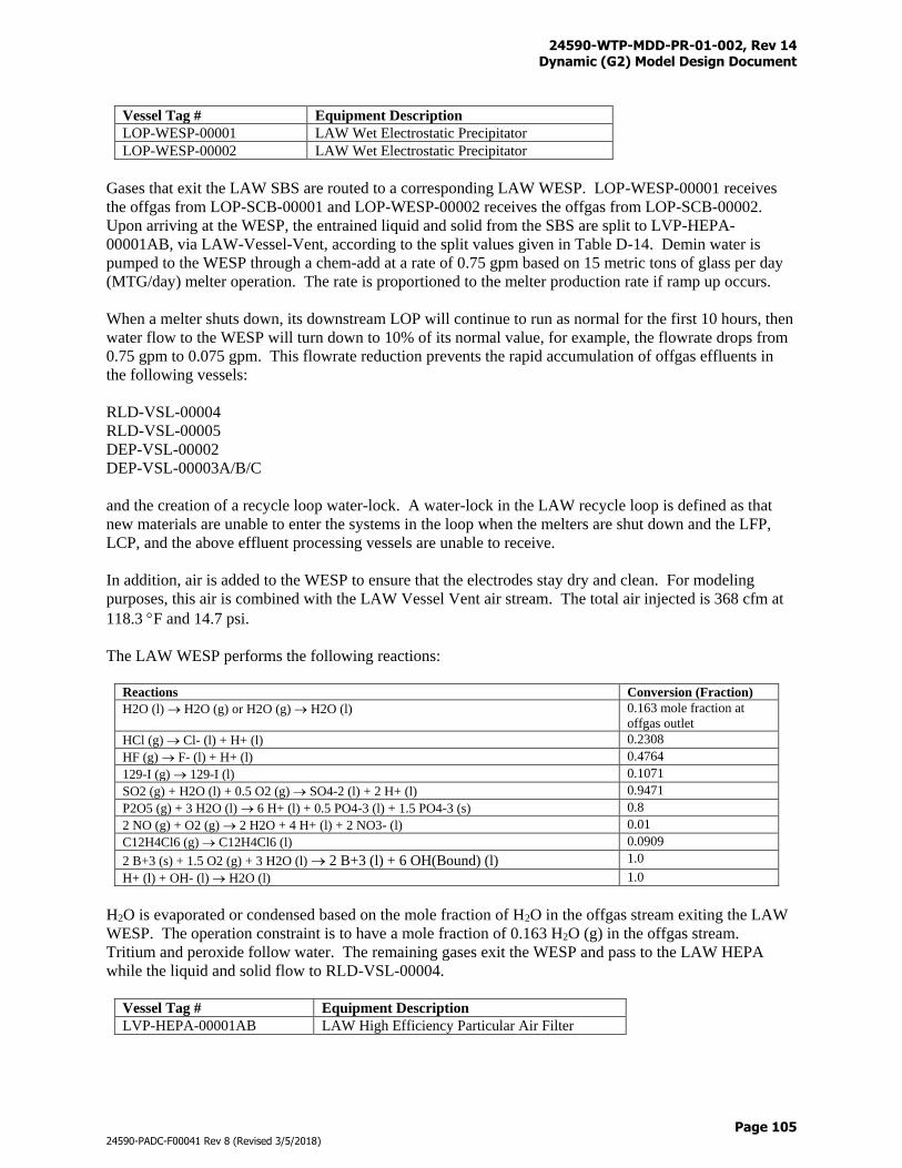
24590-WTP-MDD-PR-01-002, Rev 14 Dynamic (G2) Model Design Document
Page 105
24590-PADC-F00041 Rev 8 (Revised 3/5/2018)
Vessel Tag # Equipment Description
LOP-WESP-00001 LAW Wet Electrostatic Precipitator
LOP-WESP-00002 LAW Wet Electrostatic Precipitator
Gases that exit the LAW SBS are routed to a corresponding LAW WESP. LOP-WESP-00001 receives
the offgas from LOP-SCB-00001 and LOP-WESP-00002 receives the offgas from LOP-SCB-00002.
Upon arriving at the WESP, the entrained liquid and solid from the SBS are split to LVP-HEPA-
00001AB, via LAW-Vessel-Vent, according to the split values given in Table D-14. Demin water is
pumped to the WESP through a chem-add at a rate of 0.75 gpm based on 15 metric tons of glass per day
(MTG/day) melter operation. The rate is proportioned to the melter production rate if ramp up occurs.
When a melter shuts down, its downstream LOP will continue to run as normal for the first 10 hours, then
water flow to the WESP will turn down to 10% of its normal value, for example, the flowrate drops from
0.75 gpm to 0.075 gpm. This flowrate reduction prevents the rapid accumulation of offgas effluents in
the following vessels:
RLD-VSL-00004
RLD-VSL-00005
DEP-VSL-00002
DEP-VSL-00003A/B/C
and the creation of a recycle loop water-lock. A water-lock in the LAW recycle loop is defined as that
new materials are unable to enter the systems in the loop when the melters are shut down and the LFP,
LCP, and the above effluent processing vessels are unable to receive.
In addition, air is added to the WESP to ensure that the electrodes stay dry and clean. For modeling
purposes, this air is combined with the LAW Vessel Vent air stream. The total air injected is 368 cfm at
118.3 F and 14.7 psi.
The LAW WESP performs the following reactions:
Reactions Conversion (Fraction)
H2O (l) H2O (g) or H2O (g) H2O (l) 0.163 mole fraction at
offgas outlet
HCl (g) Cl- (l) + H+ (l) 0.2308
HF (g) F- (l) + H+ (l) 0.4764
129-I (g) 129-I (l) 0.1071
SO2 (g) + H2O (l) + 0.5 O2 (g) SO4-2 (l) + 2 H+ (l) 0.9471
P2O5 (g) + 3 H2O (l) 6 H+ (l) + 0.5 PO4-3 (l) + 1.5 PO4-3 (s) 0.8
2 NO (g) + O2 (g) 2 H2O + 4 H+ (l) + 2 NO3- (l) 0.01
C12H4Cl6 (g) C12H4Cl6 (l) 0.0909
2 B+3 (s) + 1.5 O2 (g) + 3 H2O (l) 2 B+3 (l) + 6 OH(Bound) (l) 1.0
H+ (l) + OH- (l) H2O (l) 1.0
H2O is evaporated or condensed based on the mole fraction of H2O in the offgas stream exiting the LAW
WESP. The operation constraint is to have a mole fraction of 0.163 H2O (g) in the offgas stream.
Tritium and peroxide follow water. The remaining gases exit the WESP and pass to the LAW HEPA
while the liquid and solid flow to RLD-VSL-00004.
Vessel Tag # Equipment Description
LVP-HEPA-00001AB LAW High Efficiency Particular Air Filter
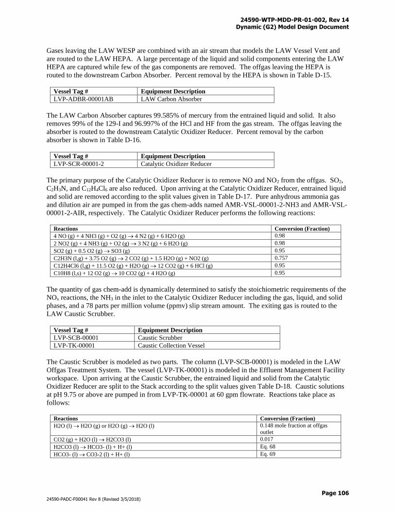
24590-WTP-MDD-PR-01-002, Rev 14 Dynamic (G2) Model Design Document
Page 106
24590-PADC-F00041 Rev 8 (Revised 3/5/2018)
Gases leaving the LAW WESP are combined with an air stream that models the LAW Vessel Vent and
are routed to the LAW HEPA. A large percentage of the liquid and solid components entering the LAW
HEPA are captured while few of the gas components are removed. The offgas leaving the HEPA is
routed to the downstream Carbon Absorber. Percent removal by the HEPA is shown in Table D-15.
Vessel Tag # Equipment Description
LVP-ADBR-00001AB LAW Carbon Absorber
The LAW Carbon Absorber captures 99.585% of mercury from the entrained liquid and solid. It also
removes 99% of the 129-I and 96.997% of the HCl and HF from the gas stream. The offgas leaving the
absorber is routed to the downstream Catalytic Oxidizer Reducer. Percent removal by the carbon
absorber is shown in Table D-16.
Vessel Tag # Equipment Description
LVP-SCR-00001-2 Catalytic Oxidizer Reducer
The primary purpose of the Catalytic Oxidizer Reducer is to remove NO and NO2 from the offgas. SO2,
C2H3N, and C12H4Cl6 are also reduced. Upon arriving at the Catalytic Oxidizer Reducer, entrained liquid
and solid are removed according to the split values given in Table D-17. Pure anhydrous ammonia gas
and dilution air are pumped in from the gas chem-adds named AMR-VSL-00001-2-NH3 and AMR-VSL-
00001-2-AIR, respectively. The Catalytic Oxidizer Reducer performs the following reactions:
Reactions Conversion (Fraction)
4 NO (g) + 4 NH3 (g) + O2 (g) 4 N2 (g) + 6 H2O (g) 0.98
2 NO2 (g) + 4 NH3 (g) + O2 (g) 3 N2 (g) + 6 H2O (g) 0.98
SO2 (g) + 0.5 O2 (g) SO3 (g) 0.95
C2H3N (l,g) + 3.75 O2 (g) 2 CO2 (g) + 1.5 H2O (g) + NO2 (g) 0.757
C12H4Cl6 (l,g) + 11.5 O2 (g) + H2O (g) 12 CO2 (g) + 6 HCl (g) 0.95
C10H8 (l,s) + 12 O2 (g) 10 CO2 (g) + 4 H2O (g) 0.95
The quantity of gas chem-add is dynamically determined to satisfy the stoichiometric requirements of the
NOx reactions, the NH3 in the inlet to the Catalytic Oxidizer Reducer including the gas, liquid, and solid
phases, and a 78 parts per million volume (ppmv) slip stream amount. The exiting gas is routed to the
LAW Caustic Scrubber.
Vessel Tag # Equipment Description
LVP-SCB-00001 Caustic Scrubber
LVP-TK-00001 Caustic Collection Vessel
The Caustic Scrubber is modeled as two parts. The column (LVP-SCB-00001) is modeled in the LAW
Offgas Treatment System. The vessel (LVP-TK-00001) is modeled in the Effluent Management Facility
workspace. Upon arriving at the Caustic Scrubber, the entrained liquid and solid from the Catalytic
Oxidizer Reducer are split to the Stack according to the split values given Table D-18. Caustic solutions
at pH 9.75 or above are pumped in from LVP-TK-00001 at 60 gpm flowrate. Reactions take place as
follows:
Reactions Conversion (Fraction)
H2O (l) H2O (g) or H2O (g) H2O (l) 0.148 mole fraction at offgas
outlet
CO2 (g) + H2O (l) H2CO3 (l) 0.017
H2CO3 (l) HCO3- (l) + H+ (l) Eq. 68
HCO3- (l) CO3-2 (l) + H+ (l) Eq. 69
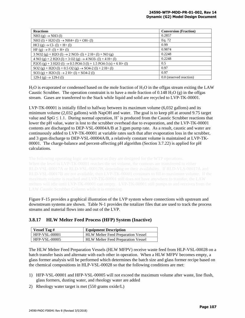
24590-WTP-MDD-PR-01-002, Rev 14 Dynamic (G2) Model Design Document
Page 107
24590-PADC-F00041 Rev 8 (Revised 3/5/2018)
Reactions Conversion (Fraction)
NH3 (g) NH3 (l) 0.2857
NH3 (l) + H2O (l) NH4+ (l) + OH- (l) Eq. 72
HCl (g) Cl- (l) + H+ (l) 0.99
HF (g) F- (l) + H+ (l) 0.9874
3 NO2 (g) + H2O (l) 2 NO3- (l) + 2 H+ (l) + NO (g) 0.2248
4 NO (g) + 2 H2O (l) + 3 O2 (g) 4 NO3- (l) + 4 H+ (l) 0.2248
P2O5 (g) + 3 H2O (l) 0.5 PO4-3 (l) + 1.5 PO4-3 (s) + 6 H+ (l) 0.5
SO2 (g) + H2O (l) + 0.5 O2 (g) SO4-2 (l) + 2 H+ (l) 0.97
SO3 (g) + H2O (l) 2 H+ (l) + SO4-2 (l) 0.97
129-I (g) 129-I (l) 0.0 (reserved reaction)
H2O is evaporated or condensed based on the mole fraction of H2O in the offgas stream exiting the LAW
Caustic Scrubber. The operation constraint is to have a mole fraction of 0.148 H2O (g) in the offgas
stream. Gases are transferred to the Stack while liquid and solid are recycled to LVP-TK-00001.
LVP-TK-00001 is initially filled to halfway between its maximum volume (6,032 gallons) and its
minimum volume (2,032 gallons) with NapOH and water. The goal is to keep pH at around 9.75 target
value and SpG ≤ 1.1. During normal operation, H+ is produced from the Caustic Scrubber reactions that
lower the pH value, water is lost to the scrubber overhead due to evaporation, and the LVP-TK-00001
contents are discharged to DEP-VSL-00004A/B at 3 gpm pump rate. As a result, caustic and water are
continuously added to LVP-TK-00001 at variable rates such that after evaporation loss in the scrubber,
and 3 gpm discharge to DEP-VSL-00004A/B, a relatively constant volume is maintained at LVP-TK-
00001. The charge-balance and percent-affecting pH algorithm (Section 3.7.22) is applied for pH
calculations.
The following operating logic are inactive as they are designed for the WTP operations.
When the level in LVP-TK-00001 reaches the set volume, the contents are transferred to either
RLD-VSL-00017A or RLD-VSL-00017B, depending on their availability. If RLD-VLS-00017A and
RLD-VSL-00017B are not available, then LVP-TK-00001 continues to fill to maximum volume. If the
maximum volume is reached and LVP-TK-00001 still does not have anywhere to transfer, the LAW
melters will idle until LVP-TK-00001 can empty. LVP-TK-00001 still pumps to and receives from the
LAW Caustic Scrubber Column while it is emptying.
Figure F-15 provides a graphical illustration of the LVP system where connections with upstream and
downstream systems are shown. Table N-1 provides the totalizer files that are used to track the process
streams and material flows into and out of the LVP.
3.8.17 HLW Melter Feed Process (HFP) System (Inactive)
Vessel Tag # Equipment Description
HFP-VSL-00001 HLW Melter Feed Preparation Vessel
HFP-VSL-00005 HLW Melter Feed Preparation Vessel
The HLW Melter Feed Preparation Vessels (HLW MFPV) receive waste feed from HLP-VSL-00028 on a
batch transfer basis and alternate with each other in operation. When a HLW MFPV becomes empty, a
glass former analysis will be performed which determines the batch size and glass former recipe based on
the chemical compositions in HLP-VSL-00028 so that the following conditions are met:
1) HFP-VSL-00001 and HFP-VSL-00005 will not exceed the maximum volume after waste, line flush,
glass formers, dusting water, and rheology water are added
2) Rheology water target is met (550 grams oxide/L)
24590-WTP-MDD-PR-01-002, Rev 14 Dynamic (G2) Model Design Document
Page 108
24590-PADC-F00041 Rev 8 (Revised 3/5/2018)
3) HLW glass quality specifications are met
The MFPV batch size is determined using the logic shown in Figure 16. The glass former recipe is
determined using the HLW Glass Shell V2.0 presented in Figures 17 through 35. Details for the
development of this HLW Glass Shell can be found in 24590-WTP-MCR-PET-09-0047 and further in the
BARD. A request is submitted to the HLW recipe queue for the Glass Former Reagent System. Glass
formers can be prepared as soon as a recipe exists in the HLW recipe queue given that the GFR is
available. LAW and HLW recipes compete for the use of GFR as there is only one in the plant (refer to
Section 3.8.22 for GFR operations). HLW recipes have higher priorities than the LAW recipes to prevent
HFP from backing up the ultrafiltration operations.
Glass former preparations can occur simultaneously with a waste batch transfer. When an HLW MFPV
has reached its set volume, it receives a line flush and a pre- determined volume of rheology water. Then
the vessel is held 15 hours for a pre- glass former sampling. The vessel will wait for the glass formers if
they are not already ready. HFP-VSL-00001 receives glass formers from GFR-TK-00031 and HFP-VSL-
00005 receives glass formers from GFR-TK-00025. The MFPV will receive 48 gallons of demister flush
water before the confirmation sample is taken. The vessel is held 25.6 hours for a confirmation sampling
prior to discharge. HFP-VSL-00001 empties its contents to HFP-VSL-00002 and HFP-VSL-00005
empties its contents to HFP-VSL-00006. After emptying, the HLW MFPV starts a new cycle.
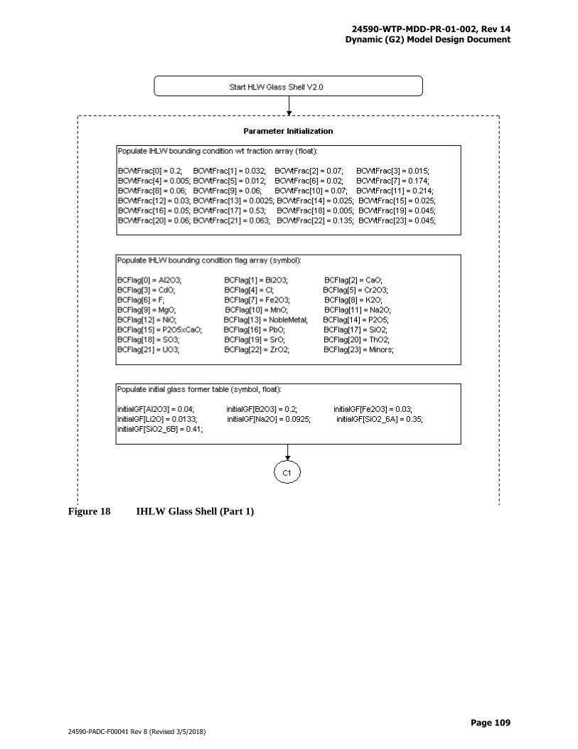
24590-WTP-MDD-PR-01-002, Rev 14 Dynamic (G2) Model Design Document
Page 109
24590-PADC-F00041 Rev 8 (Revised 3/5/2018)
Figure 18 IHLW Glass Shell (Part 1)
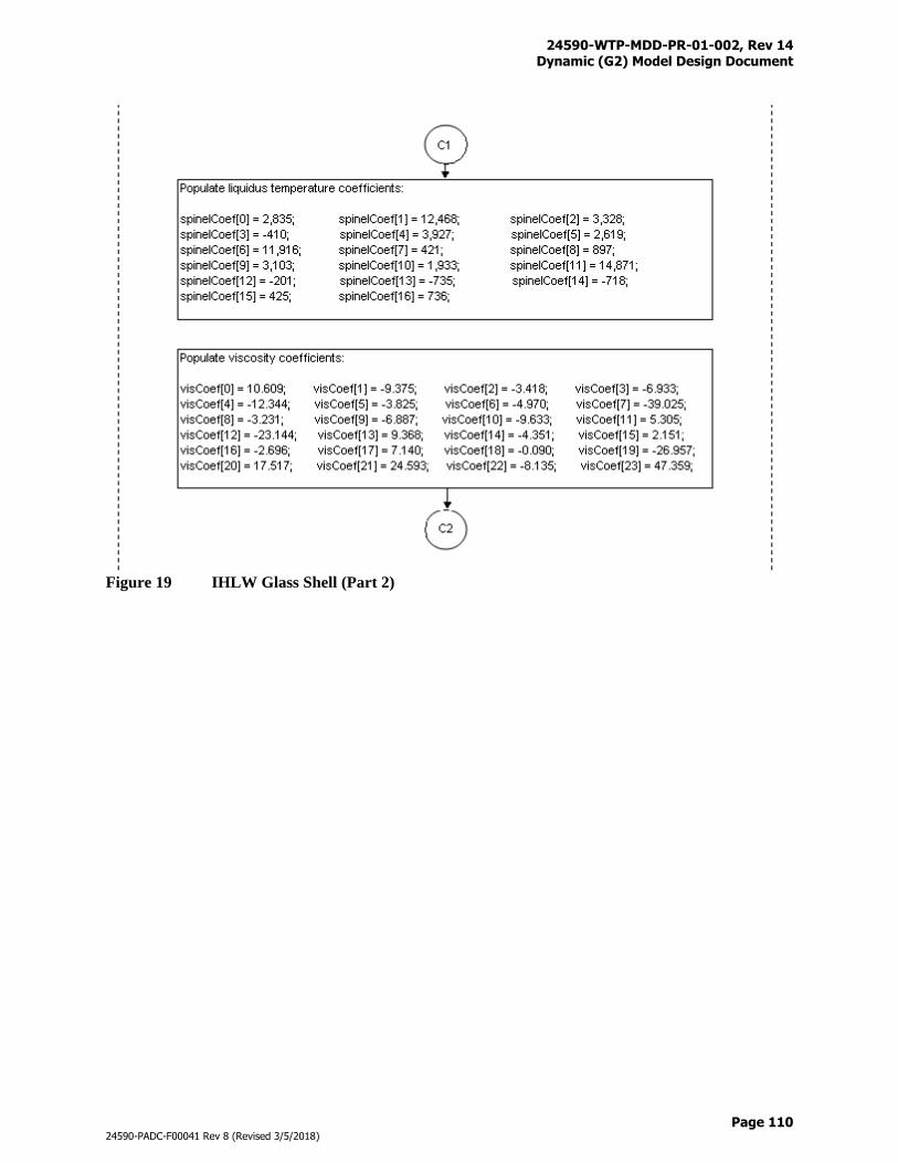
24590-WTP-MDD-PR-01-002, Rev 14 Dynamic (G2) Model Design Document
Page 110
24590-PADC-F00041 Rev 8 (Revised 3/5/2018)
Figure 19 IHLW Glass Shell (Part 2)
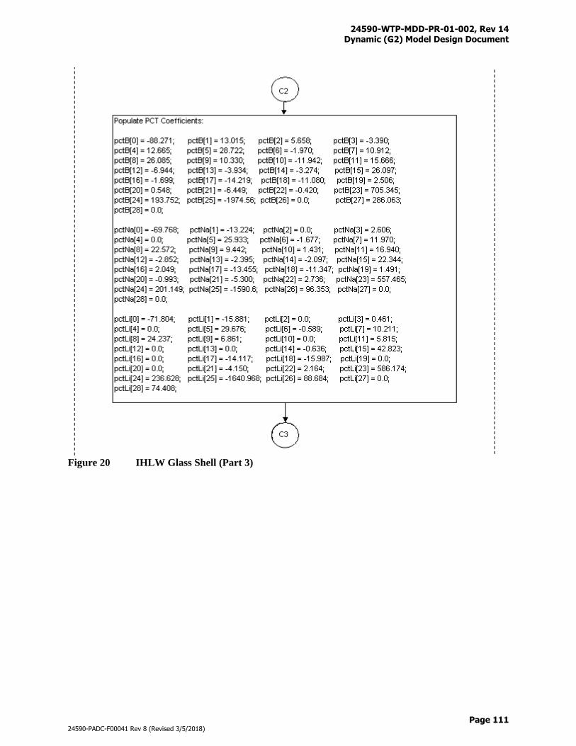
24590-WTP-MDD-PR-01-002, Rev 14 Dynamic (G2) Model Design Document
Page 111
24590-PADC-F00041 Rev 8 (Revised 3/5/2018)
Figure 20 IHLW Glass Shell (Part 3)
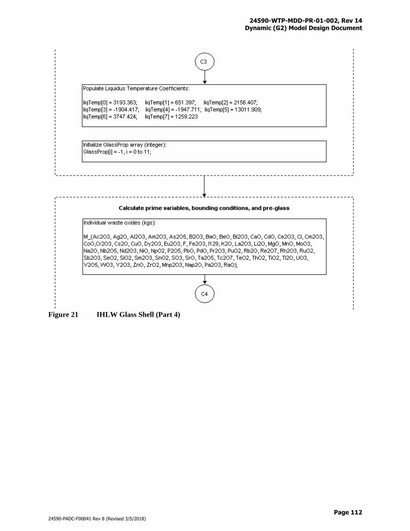
24590-WTP-MDD-PR-01-002, Rev 14 Dynamic (G2) Model Design Document
Page 112
24590-PADC-F00041 Rev 8 (Revised 3/5/2018)
Figure 21 IHLW Glass Shell (Part 4)
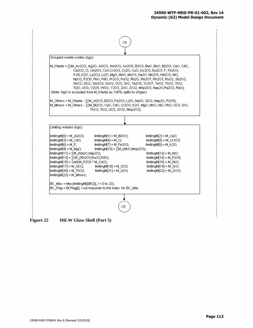
24590-WTP-MDD-PR-01-002, Rev 14 Dynamic (G2) Model Design Document
Page 113
24590-PADC-F00041 Rev 8 (Revised 3/5/2018)
Figure 22 IHLW Glass Shell (Part 5)
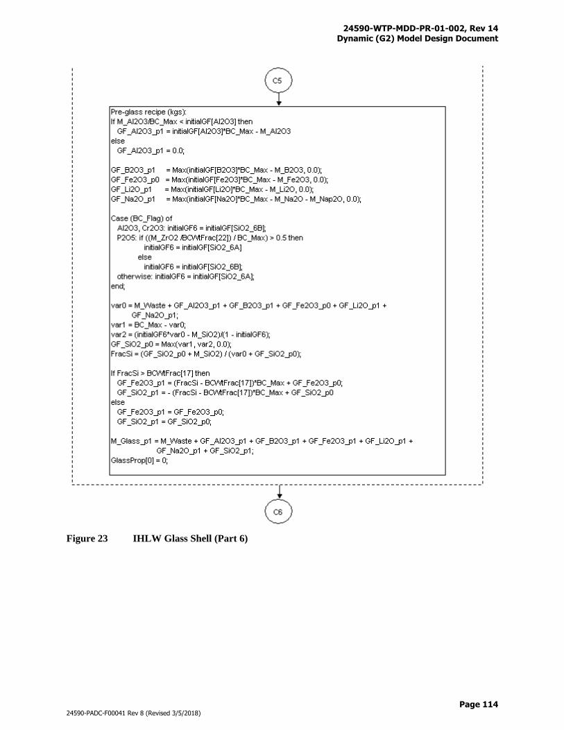
24590-WTP-MDD-PR-01-002, Rev 14 Dynamic (G2) Model Design Document
Page 114
24590-PADC-F00041 Rev 8 (Revised 3/5/2018)
Figure 23 IHLW Glass Shell (Part 6)
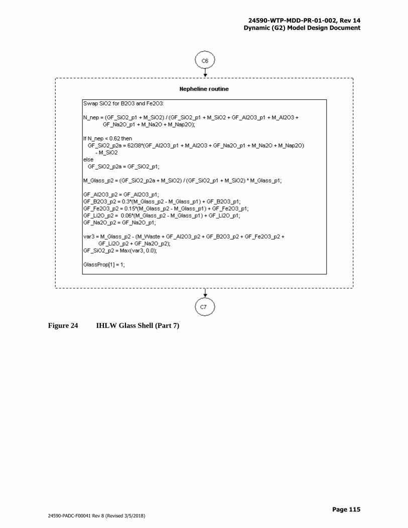
24590-WTP-MDD-PR-01-002, Rev 14 Dynamic (G2) Model Design Document
Page 115
24590-PADC-F00041 Rev 8 (Revised 3/5/2018)
Figure 24 IHLW Glass Shell (Part 7)
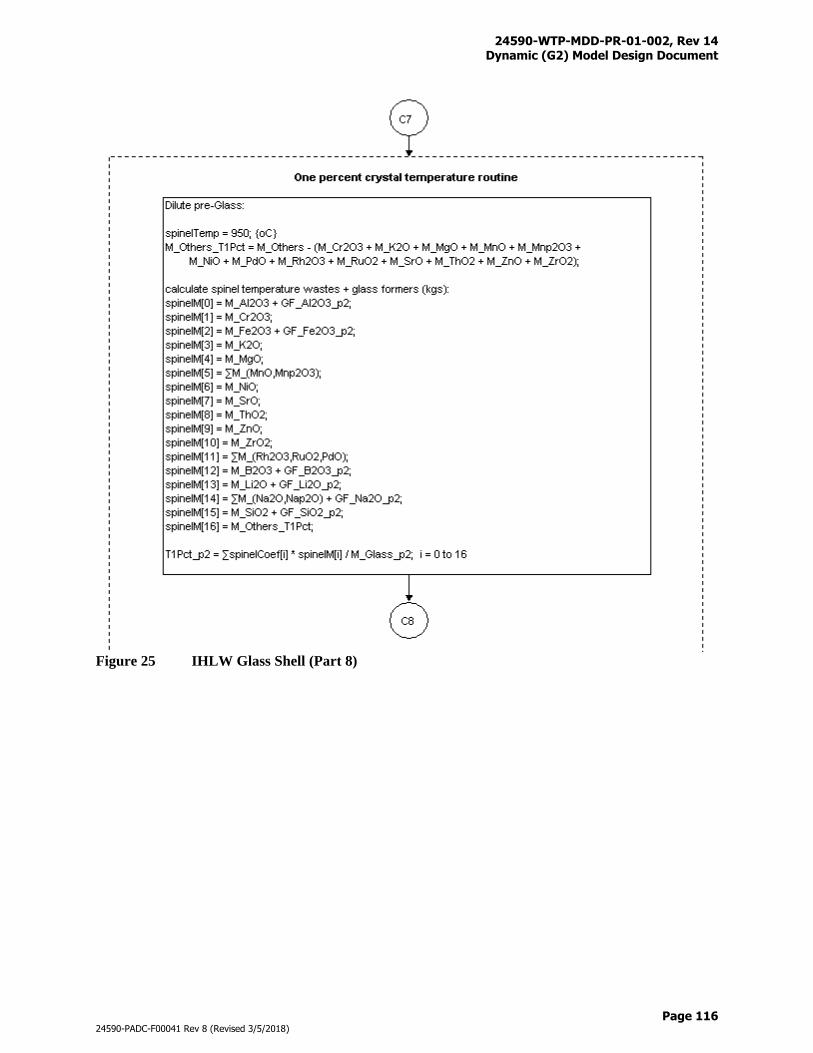
24590-WTP-MDD-PR-01-002, Rev 14 Dynamic (G2) Model Design Document
Page 116
24590-PADC-F00041 Rev 8 (Revised 3/5/2018)
Figure 25 IHLW Glass Shell (Part 8)
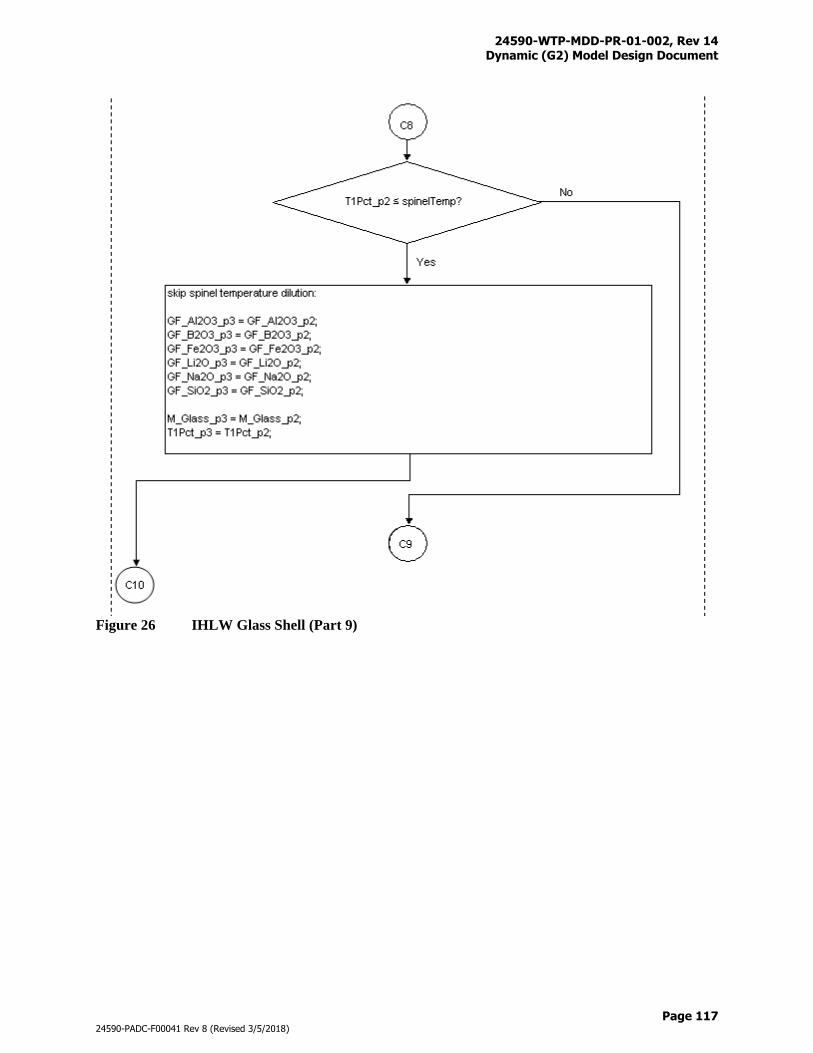
24590-WTP-MDD-PR-01-002, Rev 14 Dynamic (G2) Model Design Document
Page 117
24590-PADC-F00041 Rev 8 (Revised 3/5/2018)
Figure 26 IHLW Glass Shell (Part 9)
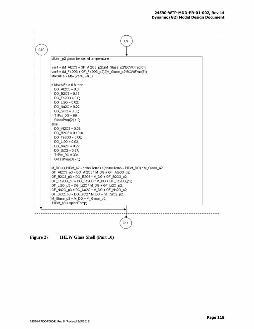
24590-WTP-MDD-PR-01-002, Rev 14 Dynamic (G2) Model Design Document
Page 118
24590-PADC-F00041 Rev 8 (Revised 3/5/2018)
Figure 27 IHLW Glass Shell (Part 10)
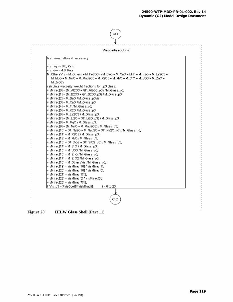
24590-WTP-MDD-PR-01-002, Rev 14 Dynamic (G2) Model Design Document
Page 119
24590-PADC-F00041 Rev 8 (Revised 3/5/2018)
Figure 28 IHLW Glass Shell (Part 11)
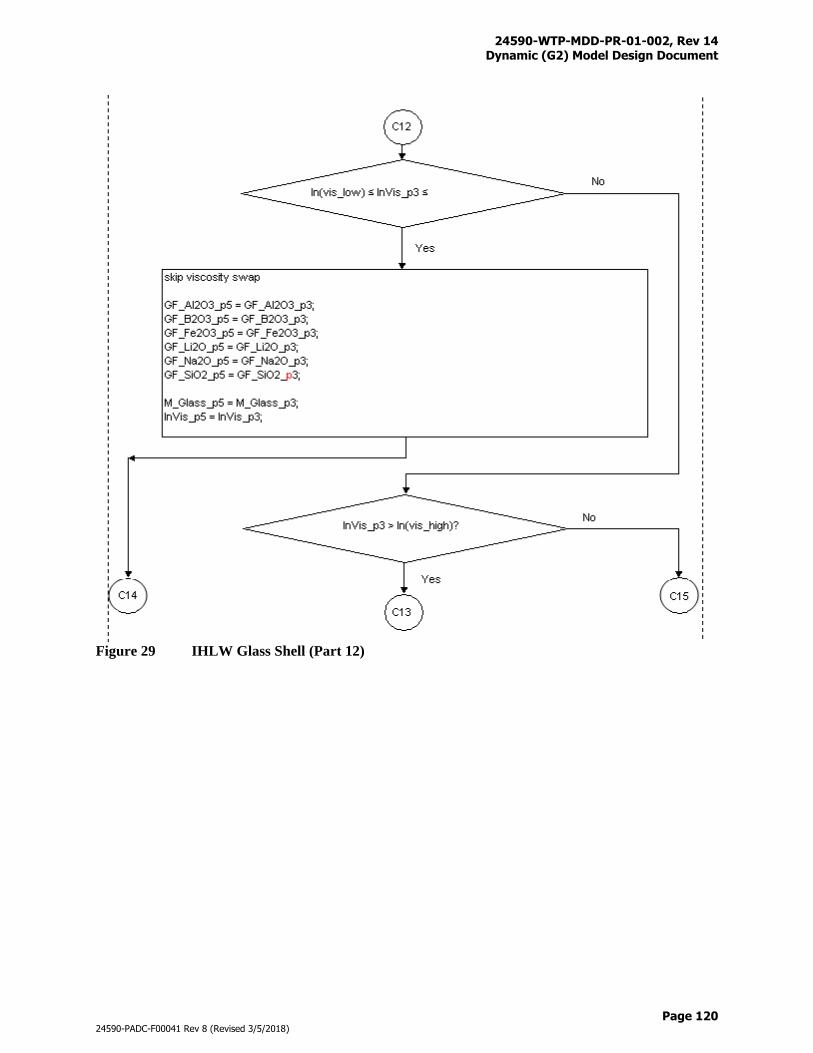
24590-WTP-MDD-PR-01-002, Rev 14 Dynamic (G2) Model Design Document
Page 120
24590-PADC-F00041 Rev 8 (Revised 3/5/2018)
Figure 29 IHLW Glass Shell (Part 12)
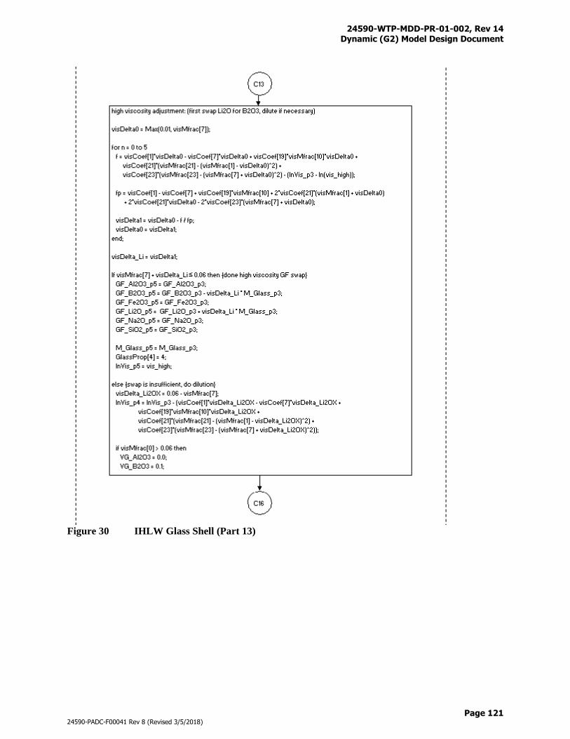
24590-WTP-MDD-PR-01-002, Rev 14 Dynamic (G2) Model Design Document
Page 121
24590-PADC-F00041 Rev 8 (Revised 3/5/2018)
Figure 30 IHLW Glass Shell (Part 13)
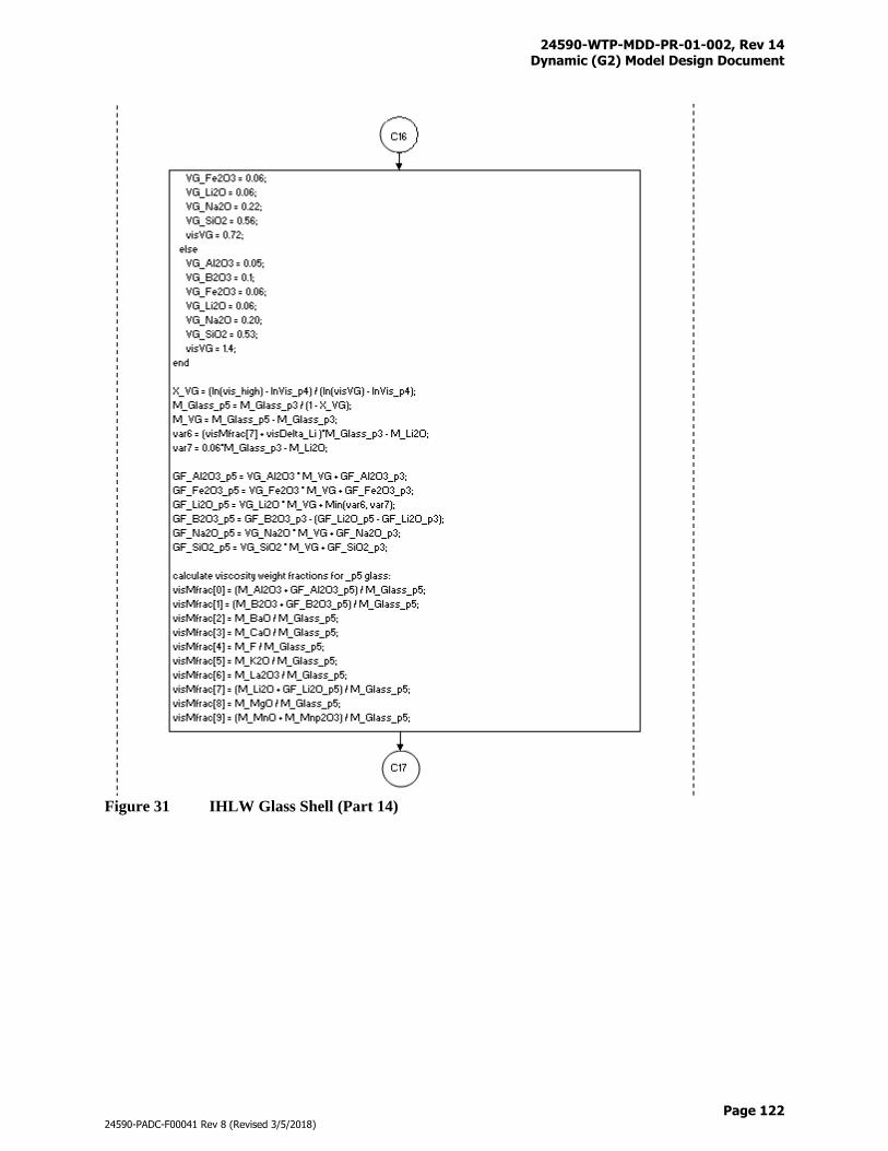
24590-WTP-MDD-PR-01-002, Rev 14 Dynamic (G2) Model Design Document
Page 122
24590-PADC-F00041 Rev 8 (Revised 3/5/2018)
Figure 31 IHLW Glass Shell (Part 14)
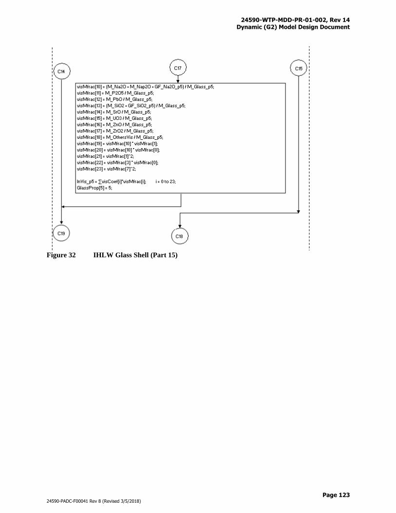
24590-WTP-MDD-PR-01-002, Rev 14 Dynamic (G2) Model Design Document
Page 123
24590-PADC-F00041 Rev 8 (Revised 3/5/2018)
Figure 32 IHLW Glass Shell (Part 15)
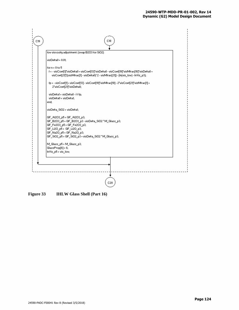
24590-WTP-MDD-PR-01-002, Rev 14 Dynamic (G2) Model Design Document
Page 124
24590-PADC-F00041 Rev 8 (Revised 3/5/2018)
Figure 33 IHLW Glass Shell (Part 16)
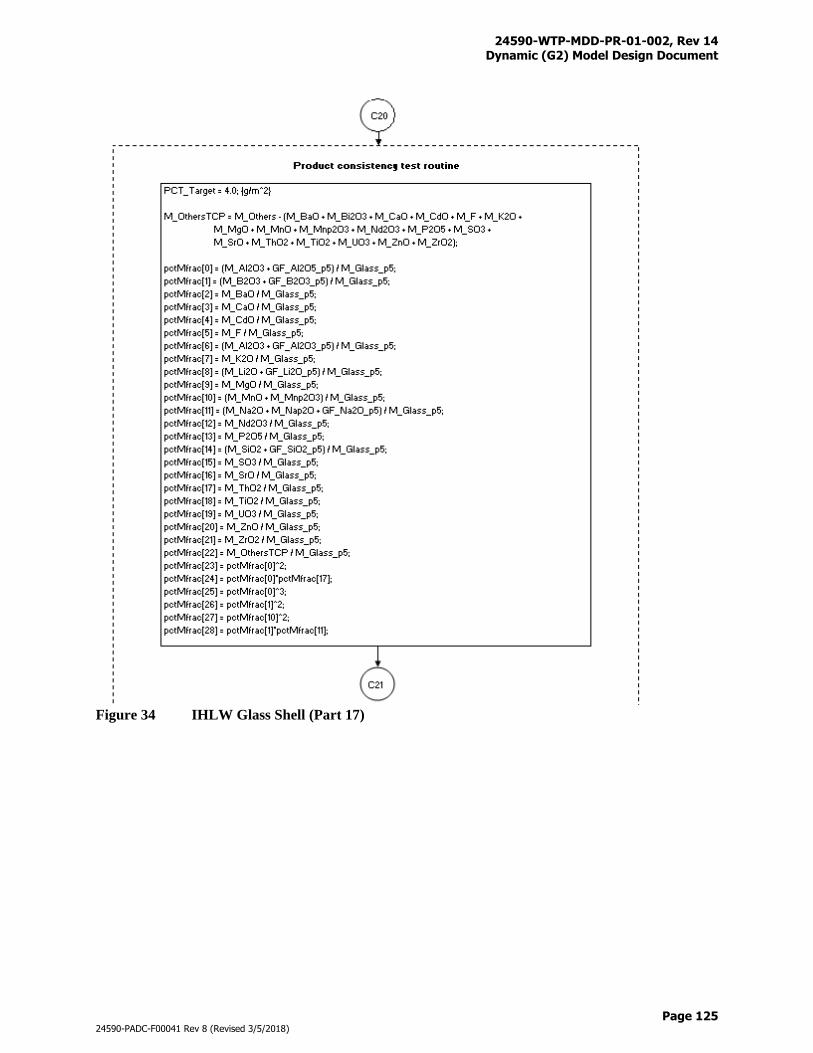
24590-WTP-MDD-PR-01-002, Rev 14 Dynamic (G2) Model Design Document
Page 125
24590-PADC-F00041 Rev 8 (Revised 3/5/2018)
Figure 34 IHLW Glass Shell (Part 17)
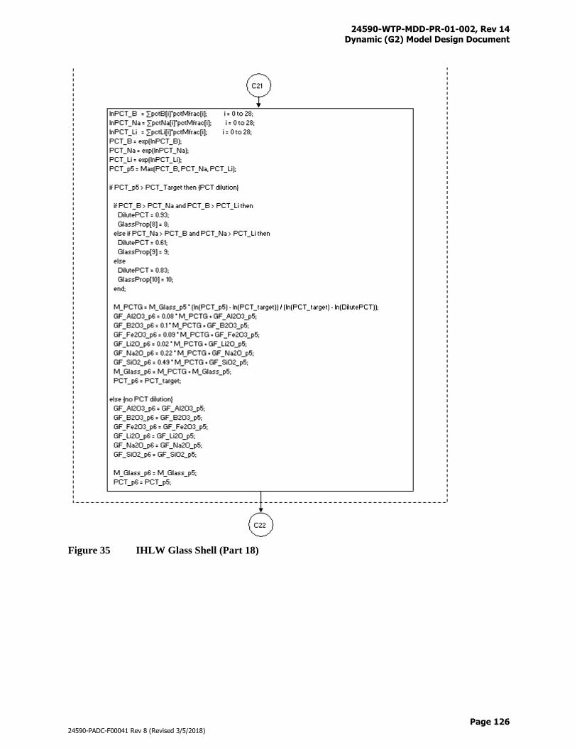
24590-WTP-MDD-PR-01-002, Rev 14 Dynamic (G2) Model Design Document
Page 126
24590-PADC-F00041 Rev 8 (Revised 3/5/2018)
Figure 35 IHLW Glass Shell (Part 18)
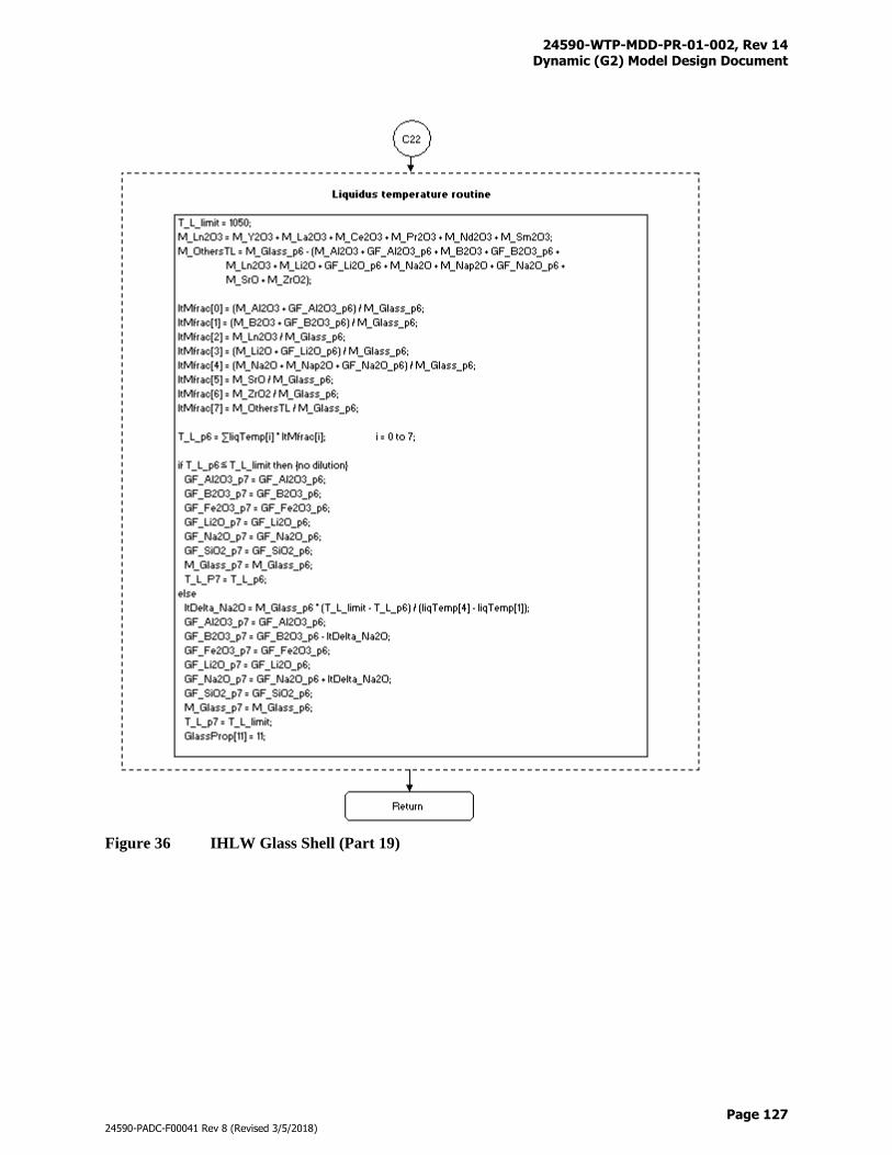
24590-WTP-MDD-PR-01-002, Rev 14 Dynamic (G2) Model Design Document
Page 127
24590-PADC-F00041 Rev 8 (Revised 3/5/2018)
Figure 36 IHLW Glass Shell (Part 19)
24590-WTP-MDD-PR-01-002, Rev 14 Dynamic (G2) Model Design Document
Page 128
24590-PADC-F00041 Rev 8 (Revised 3/5/2018)
The glass former recipe, including the quantities of borax, boric acid, kyanite, lithium carbonate, olivine,
rutile, soda ash, sugar, wollastonite, zinc oxide, and zircon sand, are returned from the Immobilized High-
Level Waste (IHLW) Glass Shell.
Vessel Tag # Equipment Description
HFP-VSL-00002 HLW Melter 1 Feed Vessel
HFP-VSL-00006 HLW Melter 2 Feed Vessel
The HLW MFVs receive feed from the corresponding HLW MFPVs. HFP-VSL-00002 transfers material
only to HMP-MLTR-00001, and HFP-VSL-00006 transfers material only to HMP-MLTR-00002. The
objective of the MFVs is to feed enough waste to the melters to maintain a set target production rate for
MTG/day. Because the composition of the waste batches is variable, the transfer rate required to maintain
the target throughput in the melters is also variable. A more diluted feed will have a higher transfer rate
so that the target melter production rate can be maintained. When an HLW MFV reaches its lower
setpoint it becomes available to receive feed again while continuing to empty to its minimum volume.
This prevents the HLW melter from becoming idle. The only time that an HLW MFV will stop pumping
to the melter is when there is no feed available from the HLW MFPV and the HLW MFV is at its
minimum volume.
The HLW melter feed pumps will be shut down temporarily when the number of canisters on the canister
decontamination system cooling rack reach the 24 capacity limit and/or when RLD-VSL-00007 is filled
but unable to discharge. The melter feed pumps resume as soon as the restricting conditions are relieved.
Figure F-18 provides the graphical illustration of the HFP system where connections with upstream and
downstream systems are shown. Table N-1 provides the totalizer files that are used to track the process
streams and material flows into and out of the HFP.
3.8.18 HLW Melter Process (HMP) System (Inactive)
Vessel Tag # Equipment Description
HMP-MLTR-00001 HLW Melter 1
HMP-MLTR-00002 HLW Melter 2
With higher HLW glass waste loading formulations that lower solids in the melter feed, melter production
rate becomes a concern. Power diverted to boiling extra water may decrease the efficiency of the melters.
A set of equations was derived in Variable HLW Melt Rate (24590-WTP-MCR-PE-13-0023) that
calculates the melter production rate as a function glass forming oxides, solids concentration, and water
concentrations in the MFV. The MCR also provides equations to determine if the melters have enough
power capability to actually produce glass calculated by the concentration based rate equations. If power
capabilities are exceeded, the MCR provides logic to trim back the production rate. Implementation of
the variable HLW melt rate is presented as follows.
1) After a HLW MFV is filled, calculate the desired melter production rate R-desire (MTG/day per
melter)
R-desired = 0.008 * Cox + 1.40 (Eq. 73)
where:
Cox = (kg waste oxide + kg glass former oxide) * 1000 (g / liter slurry).
2) Calculate the power need Pn (kW per melter)
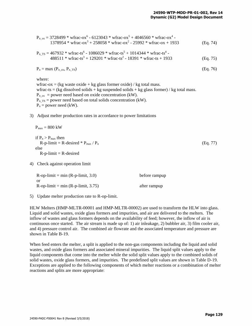
24590-WTP-MDD-PR-01-002, Rev 14 Dynamic (G2) Model Design Document
Page 129
24590-PADC-F00041 Rev 8 (Revised 3/5/2018)
Pn_ox = 3728499 * wfrac-ox6 - 6123043 * wfrac-ox5 + 4046560 * wfrac-ox4 -
1378954 * wfrac-ox3 + 258058 * wfrac-ox2 - 25992 * wfrac-ox + 1933 (Eq. 74)
Pn_TS = 467932 * wfrac-ts6 - 1086029 * wfrac-ts5 + 1014344 * wfrac-ts4 -
488511 * wfrac-ts3 + 129201 * wfrac-ts2 - 18391 * wfrac-ts + 1933 (Eq. 75)
Pn = max (Pn_ox, Pn_TS) (Eq. 76)
where:
wfrac-ox = (kg waste oxide + kg glass former oxide) / kg total mass.
wfrac-ts = (kg dissolved solids + kg suspended solids + kg glass former) / kg total mass.
Pn_ox = power need based on oxide concentration (kW).
Pn_TS = power need based on total solids concentration (kW).
Pn = power need (kW).
3) Adjust melter production rates in accordance to power limitations
Pmax = 800 kW
if Pn > Pmax then
R-p-limit = R-desired * Pmax / Pn (Eq. 77)
else
R-p-limit = R-desired
4) Check against operation limit
R-op-limit = min (R-p-limit, 3.0) before rampup
or
R-op-limit = min (R-p-limit, 3.75) after rampup
5) Update melter production rate to R-op-limit.
HLW Melters (HMP-MLTR-00001 and HMP-MLTR-00002) are used to transform the HLW into glass.
Liquid and solid wastes, oxide glass formers and impurities, and air are delivered to the melters. The
inflow of wastes and glass formers depends on the availability of feed; however, the inflow of air is
continuous once started. The air stream is made up of: 1) air inleakage, 2) bubbler air, 3) film cooler air,
and 4) pressure control air. The combined air flowrate and the associated temperature and pressure are
shown in Table B-19.
When feed enters the melter, a split is applied to the non-gas components including the liquid and solid
wastes, and oxide glass formers and associated mineral impurities. The liquid split values apply to the
liquid components that come into the melter while the solid split values apply to the combined solids of
solid wastes, oxide glass formers, and impurities. The predefined split values are shown in Table D-19.
Exceptions are applied to the following components of which melter reactions or a combination of melter
reactions and splits are more appropriate:
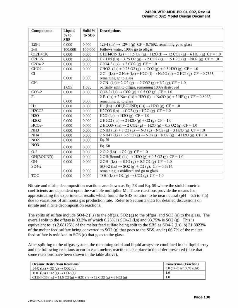
24590-WTP-MDD-PR-01-002, Rev 14 Dynamic (G2) Model Design Document
Page 130
24590-PADC-F00041 Rev 8 (Revised 3/5/2018)
Components Liquid
% to
SBS
Solid%
to SBS
Descriptions
129-I 0.000 0.000 129-I (l,s) → 129-I (g) CF = 0.7692, remaining go to glass
3-H 100.000 100.000 Follows water, 100% go to offgas
C12H4Cl6 0.000 0.000 C12H4Cl6 (l,s) + 11.5 O2 (g) + H2O (l) → 12 CO2 (g) + 6 HCl (g) CF = 1.0
C2H3N 0.000 0.000 C2H3N (l,s) + 3.75 O2 (g) → 2 CO2 (g) + 1.5 H2O (g) + NO2 (g) CF = 1.0
C2O4-2 0.000 0.000 C2O4-2 (l,s) → 2 CO2 (g) CF = 1.0
CHO2- 0.000 0.000 CHO2- (l,s) + 0.25 O2 (g) → CO2 (g) + 0.5 H2O (g) CF = 1.0
Cl-
0.000 0.000
2 Cl- (l,s) + 2 Na+ (l,s) + H2O (l) → Na2O (o) + 2 HCl (g) CF = 0.7353,
remaining go to glass
CN-
1.695 1.695
2 CN- (l,s) + 2 O2 (g) → 2 CO2 (g) + N2 (g), CF = 1.0,
partially split to offgas, remaining 100% destroyed
CO3-2 0.000 0.000 CO3-2 (l,s) → CO2 (g) + 0.5 O2 (g) CF = 1.0
F-
0.000 0.000
2 F- (l,s) + 2 Na+ (l,s) + H2O (l) → Na2O (o) + 2 HF (g) CF = 0.8065,
remaining go to glass
H+ 0.000 0.000 H+ (l,s) + OH(BOUND) (l,s) → H2O (g) CF = 1.0
H2CO3 0.000 0.000 H2CO3 (l,s) → CO2 (g) + H2O (g) CF = 1.0
H2O 0.000 0.000 H2O (l,s) → H2O (g) CF = 1.0
H2O2 0.000 0.000 2 H2O2 (l,s) → 2 H2O (g) + O2 (g) CF = 1.0
HCO3- 0.000 0.000 2 HCO3- (l,s) → 2 CO2 (g) + H2O (g) + 0.5 O2 (g) CF = 1.0
NH3 0.000 0.000 2 NH3 (l,s) + 3 O2 (g) → NO (g) + NO2 (g) + 3 H2O (g) CF = 1.0
NH4+ 0.000 0.000 2 NH4+ (l,s) + 3.5 O2 (g) → NO (g) + NO2 (g) + 4 H2O (g) CF 1.0
NO2- 0.000 0.000 Eq. 59
NO3- 0.000 0.000 Eq. 58
O-2 0.000 0.000 2 O-2 (l,s) → O2 (g) CF = 1.0
OH(BOUND) 0.000 0.000 2 OH(Bound) (l,s) → H2O (g) + 0.5 O2 (g) CF = 1.0
OH- 0.000 0.000 2 OH- (l,s) → H2O (g) + 0.5 O2 (g) CF = 1.0
SO4-2
0.000 0.000
SO4-2 (l,s) → SO2 (g) + O2 (g), CF = 0.5814,
remaining is oxidized and go to glass
TOC 0.000 0.000 TOC (l,s) + O2 (g) → CO2 (g) CF = 1.0
Nitrate and nitrite decomposition reactions are shown as Eq. 58 and Eq. 59 where the stoichiometric
coefficients are dependent upon the variable multiplier M. These reactions provide the means for
approximating the experimental results which found the SBS solution to be near neutral (pH = 6.5 to 7.5)
due to variations of ammonia gas production rate. Refer to Section 3.8.15 for detailed discussions on
nitrate and nitrite decomposition reactions.
The splits of sulfate include SO4-2 (l,s) to the offgas, SO2 (g) to the offgas, and SO3 (o) to the glass. The
overall split to the offgas is 33.3% of which 6.25% is SO4-2 (l,s) and 93.75% is SO2 (g). This is
equivalent to: a) 2.08125% of the melter feed sulfate being split to the SBS as SO4-2 (l,s), b) 31.8823%
of the melter feed sulfate being converted to SO2 (g) that goes to the SBS, and c) 66.7% of the melter
feed sulfate is oxidized to SO3 (o) that goes to the glass.
After splitting to the offgas system, the remaining solid and liquid arrays are combined in the liquid array
and the following reactions occur in each melter, reactions take place in the order presented (note that
some reactions have been shown in the table above).
Organic Destruction Reactions Conversion (Fraction)
14-C (l,s) + O2 (g) CO2 (g) 0.0 (14-C is 100% split)
TOC (l,s) + O2 (g) CO2 (g) 1.0
C12H4Cl6 (l,s) + 11.5 O2 (g) + H2O (l) 12 CO2 (g) + 6 HCl (g) 1.0
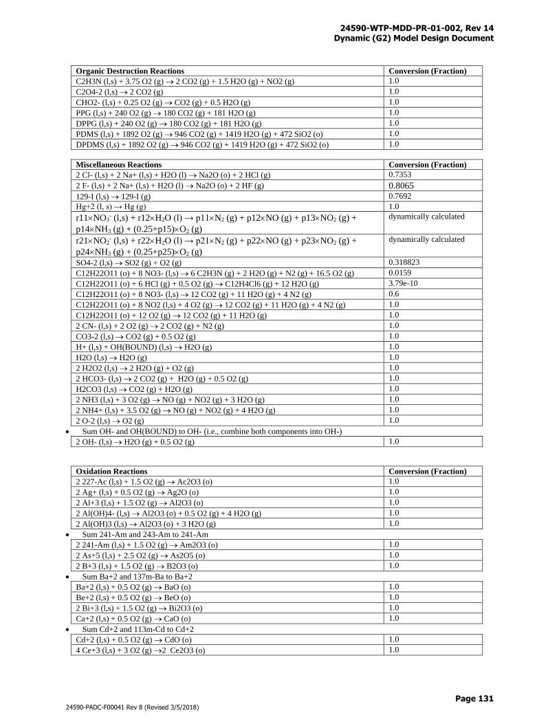
24590-WTP-MDD-PR-01-002, Rev 14 Dynamic (G2) Model Design Document
Page 131
24590-PADC-F00041 Rev 8 (Revised 3/5/2018)
Organic Destruction Reactions Conversion (Fraction)
C2H3N (l,s) + 3.75 O2 (g) 2 CO2 (g) + 1.5 H2O (g) + NO2 (g) 1.0
C2O4-2 (l,s) 2 CO2 (g) 1.0
CHO2- (l,s) + 0.25 O2 (g) CO2 (g) + 0.5 H2O (g) 1.0
PPG (l,s) + 240 O2 (g) 180 CO2 (g) + 181 H2O (g) 1.0
DPPG (l,s) + 240 O2 (g) 180 CO2 (g) + 181 H2O (g) 1.0
PDMS (l,s) + 1892 O2 (g) 946 CO2 (g) + 1419 H2O (g) + 472 SiO2 (o) 1.0
DPDMS (l,s) + 1892 O2 (g) 946 CO2 (g) + 1419 H2O (g) + 472 SiO2 (o) 1.0
Miscellaneous Reactions Conversion (Fraction)
2 Cl- (l,s) + 2 Na+ (l,s) + H2O (l) Na2O (o) + 2 HCl (g) 0.7353
2 F- (l,s) + 2 Na+ (l,s) + H2O (l) Na2O (o) + 2 HF (g) 0.8065
129-I (l,s) 129-I (g) 0.7692
Hg+2 (l, s) → Hg (g) 1.0
r11NO3- (l,s) + r12H2O (l) → p11N2 (g) + p12NO (g) + p13NO2 (g) +
p14NH3 (g) + (0.25+p15)O2 (g)
dynamically calculated
r21NO2- (l,s) + r22H2O (l) → p21N2 (g) + p22NO (g) + p23NO2 (g) +
p24NH3 (g) + (0.25+p25)O2 (g)
dynamically calculated
SO4-2 (l,s) SO2 (g) + O2 (g) 0.318823
C12H22O11 (o) + 8 NO3- (l,s) 6 C2H3N (g) + 2 H2O (g) + N2 (g) + 16.5 O2 (g) 0.0159
C12H22O11 (o) + 6 HCl (g) + 0.5 O2 (g) C12H4Cl6 (g) + 12 H2O (g) 3.79e-10
C12H22O11 (o) + 8 NO3- (l,s) 12 CO2 (g) + 11 H2O (g) + 4 N2 (g) 0.6
C12H22O11 (o) + 8 NO2 (l,s) + 4 O2 (g) 12 CO2 (g) + 11 H2O (g) + 4 N2 (g) 1.0
C12H22O11 (o) + 12 O2 (g) 12 CO2 (g) + 11 H2O (g) 1.0
2 CN- (l,s) + 2 O2 (g) 2 CO2 (g) + N2 (g) 1.0
CO3-2 (l,s) CO2 (g) + 0.5 O2 (g) 1.0
H+ (l,s) + OH(BOUND) (l,s) H2O (g) 1.0
H2O (l,s) H2O (g) 1.0
2 H2O2 (l,s) 2 H2O (g) + O2 (g) 1.0
2 HCO3- (l,s) 2 CO2 (g) + H2O (g) + 0.5 O2 (g) 1.0
H2CO3 (l,s) CO2 (g) + H2O (g) 1.0
2 NH3 (l,s) + 3 O2 (g) NO (g) + NO2 (g) + 3 H2O (g) 1.0
2 NH4+ (l,s) + 3.5 O2 (g) NO (g) + NO2 (g) + 4 H2O (g) 1.0
2 O-2 (l,s) O2 (g) 1.0
Sum OH- and OH(BOUND) to OH- (i.e., combine both components into OH-)
2 OH- (l,s) H2O (g) + 0.5 O2 (g) 1.0
Oxidation Reactions Conversion (Fraction)
2 227-Ac (l,s) + 1.5 O2 (g) Ac2O3 (o) 1.0
2 Ag+ (l,s) + 0.5 O2 (g) Ag2O (o) 1.0
2 Al+3 (l,s) + 1.5 O2 (g) Al2O3 (o) 1.0
2 Al(OH)4- (l,s) Al2O3 (o) + 0.5 O2 (g) + 4 H2O (g) 1.0
2 Al(OH)3 (l,s) Al2O3 (o) + 3 H2O (g) 1.0
Sum 241-Am and 243-Am to 241-Am
2 241-Am (l,s) + 1.5 O2 (g) Am2O3 (o) 1.0
2 As+5 (l,s) + 2.5 O2 (g) As2O5 (o) 1.0
2 B+3 (l,s) + 1.5 O2 (g) B2O3 (o) 1.0
Sum Ba+2 and 137m-Ba to Ba+2
Ba+2 (l,s) + 0.5 O2 (g) BaO (o) 1.0
Be+2 (l,s) + 0.5 O2 (g) BeO (o) 1.0
2 Bi+3 (l,s) + 1.5 O2 (g) Bi2O3 (o) 1.0
Ca+2 (l,s) + 0.5 O2 (g) CaO (o) 1.0
Sum Cd+2 and 113m-Cd to Cd+2
Cd+2 (l,s) + 0.5 O2 (g) CdO (o) 1.0
4 Ce+3 (l,s) + 3 O2 (g) 2 Ce2O3 (o) 1.0
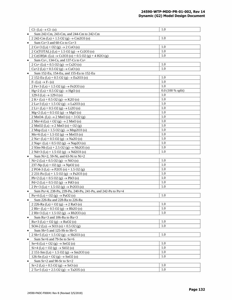
24590-WTP-MDD-PR-01-002, Rev 14 Dynamic (G2) Model Design Document
Page 132
24590-PADC-F00041 Rev 8 (Revised 3/5/2018)
Cl- (l,s) Cl- (o) 1.0
Sum 242-Cm, 243-Cm, and 244-Cm to 242-Cm
2 242-Cm (l,s) + 1.5 O2 (g) Cm2O3 (o) 1.0
Sum Co+3 and 60-Co to Co+3
2 Co+3 (l,s) + O2 (g) 2 CoO (o) 1.0
2 Cr(TOTAL) (l,s) + 1.5 O2 (g) Cr2O3 (o) 1.0
2 Cr(OH)4- (l,s) Cr2O3 (o) + 0.5 O2 (g) + 4 H2O (g) 1.0
Sum Cs+, 134-Cs, and 137-Cs to Cs+
2 Cs+ (l,s) + 0.5 O2 (g) Cs2O (o) 1.0
Cu+2 (l,s) + 0.5 O2 (g) CuO (o) 1.0
Sum 152-Eu, 154-Eu, and 155-Eu to 152-Eu
2 152-Eu (l,s) + 0.5 O2 (g) Eu2O3 (o) 1.0
F- (l,s) F- (o) 1.0
2 Fe+3 (l,s) + 1.5 O2 (g) Fe2O3 (o) 1.0
Hg+2 (l,s) + 0.5 O2 (g) HgO (o) 0.0 (100 % split)
129-I (l,s) 129-I (o) 1.0
2 K+ (l,s) + 0.5 O2 (g) K2O (o) 1.0
2 La+3 (l,s) + 1.5 O2 (g) La2O3 (o) 1.0
2 Li+ (l,s) + 0.5 O2 (g) Li2O (o) 1.0
Mg+2 (l,s) + 0.5 O2 (g) MgO (o) 1.0
2 MnO4- (l,s) 2 MnO (o) + 3 O2 (g) 1.0
2 Mn+4 (l,s) + O2 (g) 2 MnO (o) 1.0
2 MnO2 (l,s) 2 MnO (o) + O2 (g) 1.0
2 Mnp (l,s) + 1.5 O2 (g) Mnp2O3 (o) 1.0
Mo+6 (l,s) + 1.5 O2 (g) MoO3 (o) 1.0
2 Na+ (l,s) + 0.5 O2 (g) Na2O (o) 1.0
2 Nap+ (l,s) + 0.5 O2 (g) Nap2O (o) 1.0
2 93m-Nb (l,s) + 2.5 O2 (g) Nb2O5 (o) 1.0
2 Nd+3 (l,s) + 1.5 O2 (g) Nd2O3 (o) 1.0
Sum Ni+2, 59-Ni, and 63-Ni to Ni+2
Ni+2 (l,s) + 0.5 O2 (g) NiO (o) 1.0
237-Np (l,s) + O2 (g) NpO2 (o) 1.0
2 PO4-3 (l,s) P2O5 (o) + 1.5 O2 (g) 1.0
2 231-Pa (l,s) + 1.5 O2 (g) Pa2O3 (o) 1.0
Pb+2 (l,s) + 0.5 O2 (g) PbO (o) 1.0
Pd+2 (l,s) + 0.5 O2 (g) PdO (o) 1.0
2 Pr+3 (l,s) + 1.5 O2 (g) Pr2O3 (o) 1.0
Sum Pu+4, 238-Pu, 239-Pu, 240-Pu, 241-Pu, and 242-Pu to Pu+4
Pu+4 (l,s) + O2 (g) PuO2 (o) 1.0
Sum 226-Ra and 228-Ra to 226-Ra
2 226-Ra (l,s) + O2 (g) 2 RaO (o) 1.0
2 Rb+ (l,s) + 0.5 O2 (g) Rb2O (o) 1.0
2 Rh+3 (l,s) + 1.5 O2 (g) Rh2O3 (o) 1.0
Sum Ru+3 and 106-Ru to Ru+3
Ru+3 (l,s) + O2 (g) RuO2 (o) 1.0
SO4-2 (l,s) SO3 (o) + 0.5 O2 (g) 1.0
Sum Sb+5 and 125-Sb to Sb+5
2 Sb+5 (l,s) + 1.5 O2 (g) Sb2O3 (o) 1.0
Sum Se+6 and 79-Se to Se+6
Se+6 (l,s) + O2 (g) SeO2 (o) 1.0
Si+4 (l,s) + O2 (g) SiO2 (o) 1.0
2 151-Sm (l,s) + 1.5 O2 (g) Sm2O3 (o) 1.0
126-Sn (l,s) + O2 (g) SnO2 (o) 1.0
Sum Sr+2 and 90-Sr to Sr+2
Sr+2 (l,s) + 0.5 O2 (g) SrO (o) 1.0
2 Ta+5 (l,s) + 2.5 O2 (g) Ta2O5 (o) 1.0
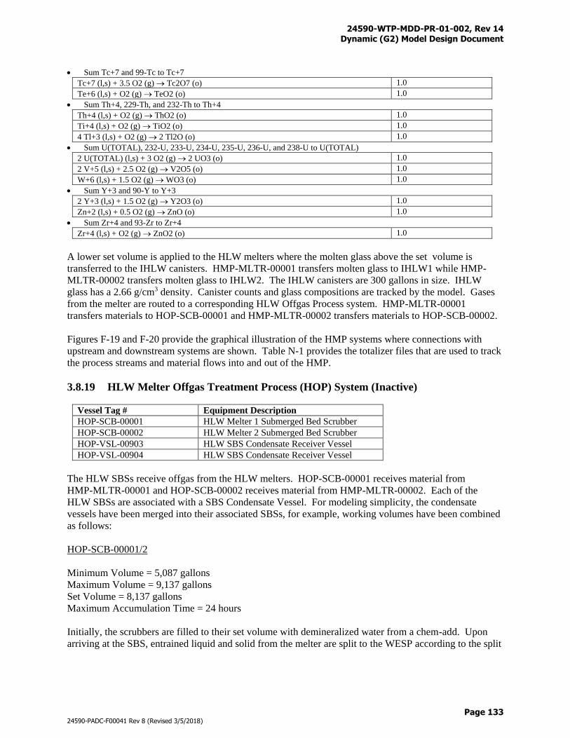
24590-WTP-MDD-PR-01-002, Rev 14 Dynamic (G2) Model Design Document
Page 133
24590-PADC-F00041 Rev 8 (Revised 3/5/2018)
Sum Tc+7 and 99-Tc to Tc+7
Tc+7 (l,s) + 3.5 O2 (g) Tc2O7 (o) 1.0
Te+6 (l,s) + O2 (g) TeO2 (o) 1.0
Sum Th+4, 229-Th, and 232-Th to Th+4
Th+4 (l,s) + O2 (g) ThO2 (o) 1.0
Ti+4 (l,s) + O2 (g) TiO2 (o) 1.0
4 Tl+3 (l,s) + O2 (g) 2 Tl2O (o) 1.0
Sum U(TOTAL), 232-U, 233-U, 234-U, 235-U, 236-U, and 238-U to U(TOTAL)
2 U(TOTAL) (l,s) + 3 O2 (g) 2 UO3 (o) 1.0
2 V+5 (l,s) + 2.5 O2 (g) V2O5 (o) 1.0
W+6 (l,s) + 1.5 O2 (g) WO3 (o) 1.0
Sum Y+3 and 90-Y to Y+3
2 Y+3 (l,s) + 1.5 O2 (g) Y2O3 (o) 1.0
Zn+2 (l,s) + 0.5 O2 (g) ZnO (o) 1.0
Sum Zr+4 and 93-Zr to Zr+4
Zr+4 (l,s) + O2 (g) ZnO2 (o) 1.0
A lower set volume is applied to the HLW melters where the molten glass above the set volume is
transferred to the IHLW canisters. HMP-MLTR-00001 transfers molten glass to IHLW1 while HMP-
MLTR-00002 transfers molten glass to IHLW2. The IHLW canisters are 300 gallons in size. IHLW
glass has a 2.66 g/cm3 density. Canister counts and glass compositions are tracked by the model. Gases
from the melter are routed to a corresponding HLW Offgas Process system. HMP-MLTR-00001
transfers materials to HOP-SCB-00001 and HMP-MLTR-00002 transfers materials to HOP-SCB-00002.
Figures F-19 and F-20 provide the graphical illustration of the HMP systems where connections with
upstream and downstream systems are shown. Table N-1 provides the totalizer files that are used to track
the process streams and material flows into and out of the HMP.
3.8.19 HLW Melter Offgas Treatment Process (HOP) System (Inactive)
Vessel Tag # Equipment Description
HOP-SCB-00001 HLW Melter 1 Submerged Bed Scrubber
HOP-SCB-00002 HLW Melter 2 Submerged Bed Scrubber
HOP-VSL-00903 HLW SBS Condensate Receiver Vessel
HOP-VSL-00904 HLW SBS Condensate Receiver Vessel
The HLW SBSs receive offgas from the HLW melters. HOP-SCB-00001 receives material from
HMP-MLTR-00001 and HOP-SCB-00002 receives material from HMP-MLTR-00002. Each of the
HLW SBSs are associated with a SBS Condensate Vessel. For modeling simplicity, the condensate
vessels have been merged into their associated SBSs, for example, working volumes have been combined
as follows:
HOP-SCB-00001/2
Minimum Volume = 5,087 gallons
Maximum Volume = 9,137 gallons
Set Volume = 8,137 gallons
Maximum Accumulation Time = 24 hours
Initially, the scrubbers are filled to their set volume with demineralized water from a chem-add. Upon
arriving at the SBS, entrained liquid and solid from the melter are split to the WESP according to the split
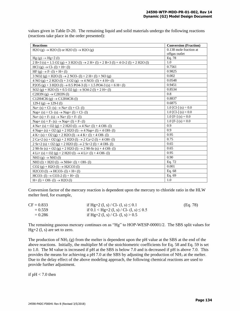
24590-WTP-MDD-PR-01-002, Rev 14 Dynamic (G2) Model Design Document
Page 134
24590-PADC-F00041 Rev 8 (Revised 3/5/2018)
values given in Table D-20. The remaining liquid and solid materials undergo the following reactions
(reactions take place in the order presented):
Reactions Conversion (Fraction)
H2O (g) H2O (l) or H2O (l) H2O (g) 0.138 mole fraction at
offgas outlet
Hg (g) → Hg+2 (l) Eq. 78
2 B+3 (s) + 1.5 O2 (g) + 3 H2O (l) 2 H+ (l) + 2 B+3 (l) + 4 O-2 (l) + 2 H2O (l) 1.0
HCl (g) Cl- (l) + H+ (l) 0.7561
HF (g) F- (l) + H+ (l) 0.9825
3 NO2 (g) + H2O (l) 2 NO3- (l) + 2 H+ (l) + NO (g) 0.002
4 NO (g) + 2 H2O (l) + 3 O2 (g) 4 NO3- (l) + 4 H+ (l) 0.0548
P2O5 (g) + 3 H2O (l) 0.5 PO4-3 (l) + 1.5 PO4-3 (s) + 6 H+ (l) 0.9451
SO2 (g) + H2O (l) + 0.5 O2 (g) SO4-2 (l) + 2 H+ (l) 0.8534
C2H3N (g) C2H3N (l) 0.8
C12H4Cl6 (g) C12H4Cl6 (l) 0.8837
129-I (g) 129-I (l) 0.6875
Na+ (s) + Cl- (s) Na+ (l) + Cl- (l) 1.0 [Cl-] (s) = 0.0
Nap+ (s) + Cl- (s) Nap+ (l) + Cl- (l) 1.0 [Cl-] (s) = 0.0
Na+ (s) + F- (s) Na+ (l) + F- (l) 1.0 [F-] (s) = 0.0
Nap+ (s) + F- (s) Nap+ (l) + F- (l) 1.0 [F-] (s) = 0.0
4 Na+ (s) + O2 (g) + 2 H2O (l) 4 Na+ (l) + 4 OH- (l) 0.9
4 Nap+ (s) + O2 (g) + 2 H2O (l) 4 Nap+ (l) + 4 OH- (l) 0.9
4 K+ (s) + O2 (g) + 2 H2O (l) 4 K+ (l) + 4 OH- (l) 0.95
2 Ca+2 (s) + O2 (g) + 2 H2O (l) 2 Ca+2 (l) + 4 OH- (l) 0.75
2 Sr+2 (s) + O2 (g) + 2 H2O (l) 2 Sr+2 (l) + 4 OH- (l) 0.65
2 90-Sr (s) + O2 (g) + 2 H2O (l) 2 90-Sr (s) + 4 OH- (l) 0.65
4 Li+ (s) + O2 (g) + 2 H2O (l) 4 Li+ (l) + 4 OH- (l) 0.95
NH3 (g) NH3 (l) 0.90
NH3 (l) + H2O (l) NH4+ (l) + OH- (l) Eq. 72
CO2 (g) + H2O (l) H2CO3 (l) 0.001
H2CO3 (l) HCO3- (l) + H+ (l) Eq. 68
HCO3- (l) CO3-2 (l) + H+ (l) Eq. 69
H+ (l) + OH- (l) H2O (l) 1.0
Conversion factor of the mercury reaction is dependent upon the mercury to chloride ratio in the HLW
melter feed, for example,
CF = 0.833 if Hg+2 (l, s) / Cl- (l, s) ≤ 0.1 (Eq. 78)
= 0.559 if 0.1 < Hg+2 (l, s) / Cl- (l, s) ≤ 0.5
= 0.286 if Hg+2 (l, s) / Cl- (l, s) > 0.5
The remaining gaseous mercury continues on as “Hg” to HOP-WESP-00001/2. The SBS split values for
Hg+2 (l, s) are set to zero.
The production of NH3 (g) from the melter is dependent upon the pH value at the SBS at the end of the
above reactions. Initially, the multiplier M of the stoichiometric coefficients for Eq. 58 and Eq. 59 is set
to 1.0. The M value is increased if pH at the SBS is below 7.0 and is decreased if pH is above 7.0. This
provides the means for achieving a pH 7.0 at the SBS by adjusting the production of NH3 at the melter.
Due to the delay effect of the above modeling approach, the following chemical reactions are used to
provide further adjustment.
if pH < 7.0 then
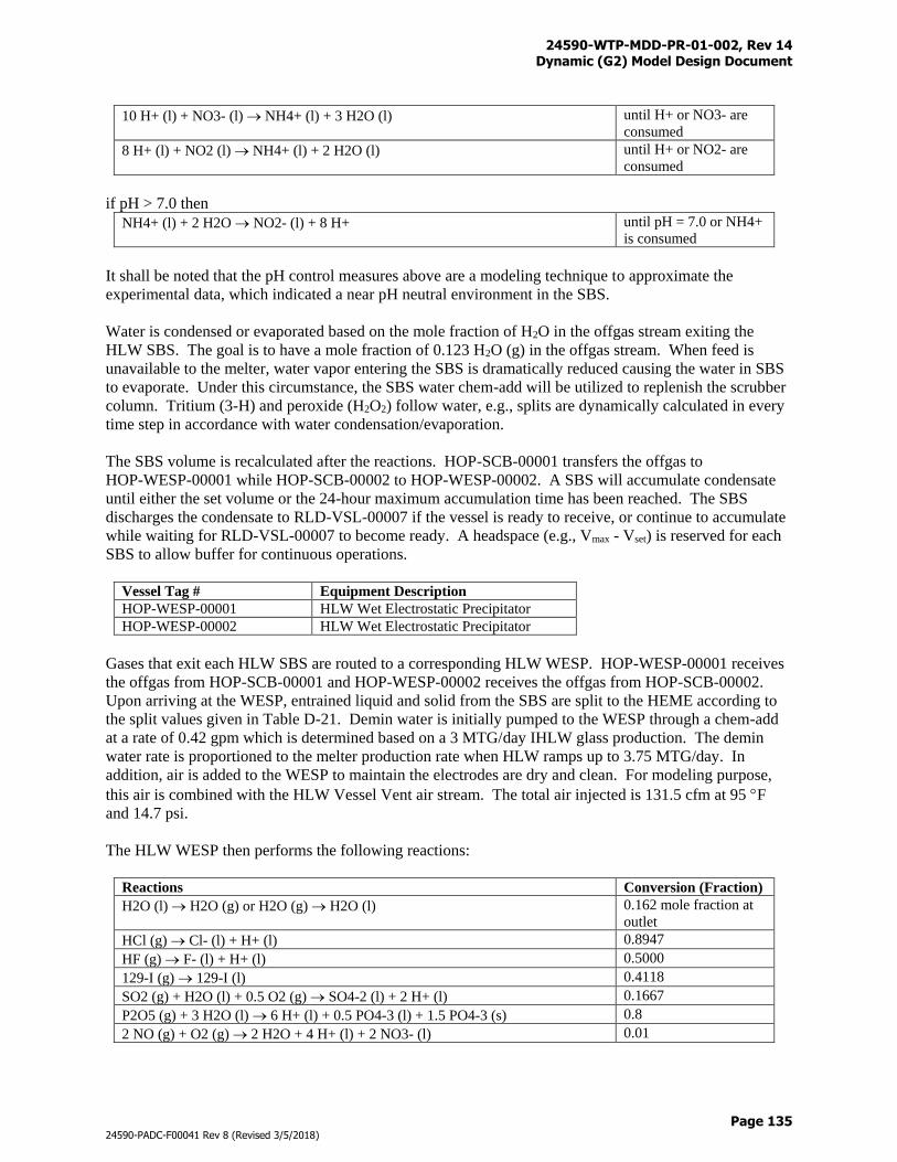
24590-WTP-MDD-PR-01-002, Rev 14 Dynamic (G2) Model Design Document
Page 135
24590-PADC-F00041 Rev 8 (Revised 3/5/2018)
10 H+ (l) + NO3- (l) NH4+ (l) + 3 H2O (l) until H+ or NO3- are
consumed
8 H+ (l) + NO2 (l) NH4+ (l) + 2 H2O (l) until H+ or NO2- are
consumed
if pH > 7.0 then
NH4+ (l) + 2 H2O NO2- (l) + 8 H+ until pH = 7.0 or NH4+
is consumed
It shall be noted that the pH control measures above are a modeling technique to approximate the
experimental data, which indicated a near pH neutral environment in the SBS.
Water is condensed or evaporated based on the mole fraction of H2O in the offgas stream exiting the
HLW SBS. The goal is to have a mole fraction of 0.123 H2O (g) in the offgas stream. When feed is
unavailable to the melter, water vapor entering the SBS is dramatically reduced causing the water in SBS
to evaporate. Under this circumstance, the SBS water chem-add will be utilized to replenish the scrubber
column. Tritium (3-H) and peroxide (H2O2) follow water, e.g., splits are dynamically calculated in every
time step in accordance with water condensation/evaporation.
The SBS volume is recalculated after the reactions. HOP-SCB-00001 transfers the offgas to
HOP-WESP-00001 while HOP-SCB-00002 to HOP-WESP-00002. A SBS will accumulate condensate
until either the set volume or the 24-hour maximum accumulation time has been reached. The SBS
discharges the condensate to RLD-VSL-00007 if the vessel is ready to receive, or continue to accumulate
while waiting for RLD-VSL-00007 to become ready. A headspace (e.g., Vmax - Vset) is reserved for each
SBS to allow buffer for continuous operations.
Vessel Tag # Equipment Description
HOP-WESP-00001 HLW Wet Electrostatic Precipitator
HOP-WESP-00002 HLW Wet Electrostatic Precipitator
Gases that exit each HLW SBS are routed to a corresponding HLW WESP. HOP-WESP-00001 receives
the offgas from HOP-SCB-00001 and HOP-WESP-00002 receives the offgas from HOP-SCB-00002.
Upon arriving at the WESP, entrained liquid and solid from the SBS are split to the HEME according to
the split values given in Table D-21. Demin water is initially pumped to the WESP through a chem-add
at a rate of 0.42 gpm which is determined based on a 3 MTG/day IHLW glass production. The demin
water rate is proportioned to the melter production rate when HLW ramps up to 3.75 MTG/day. In
addition, air is added to the WESP to maintain the electrodes are dry and clean. For modeling purpose,
this air is combined with the HLW Vessel Vent air stream. The total air injected is 131.5 cfm at 95 F
and 14.7 psi.
The HLW WESP then performs the following reactions:
Reactions Conversion (Fraction)
H2O (l) H2O (g) or H2O (g) H2O (l) 0.162 mole fraction at
outlet
HCl (g) Cl- (l) + H+ (l) 0.8947
HF (g) F- (l) + H+ (l) 0.5000
129-I (g) 129-I (l) 0.4118
SO2 (g) + H2O (l) + 0.5 O2 (g) SO4-2 (l) + 2 H+ (l) 0.1667
P2O5 (g) + 3 H2O (l) 6 H+ (l) + 0.5 PO4-3 (l) + 1.5 PO4-3 (s) 0.8
2 NO (g) + O2 (g) 2 H2O + 4 H+ (l) + 2 NO3- (l) 0.01
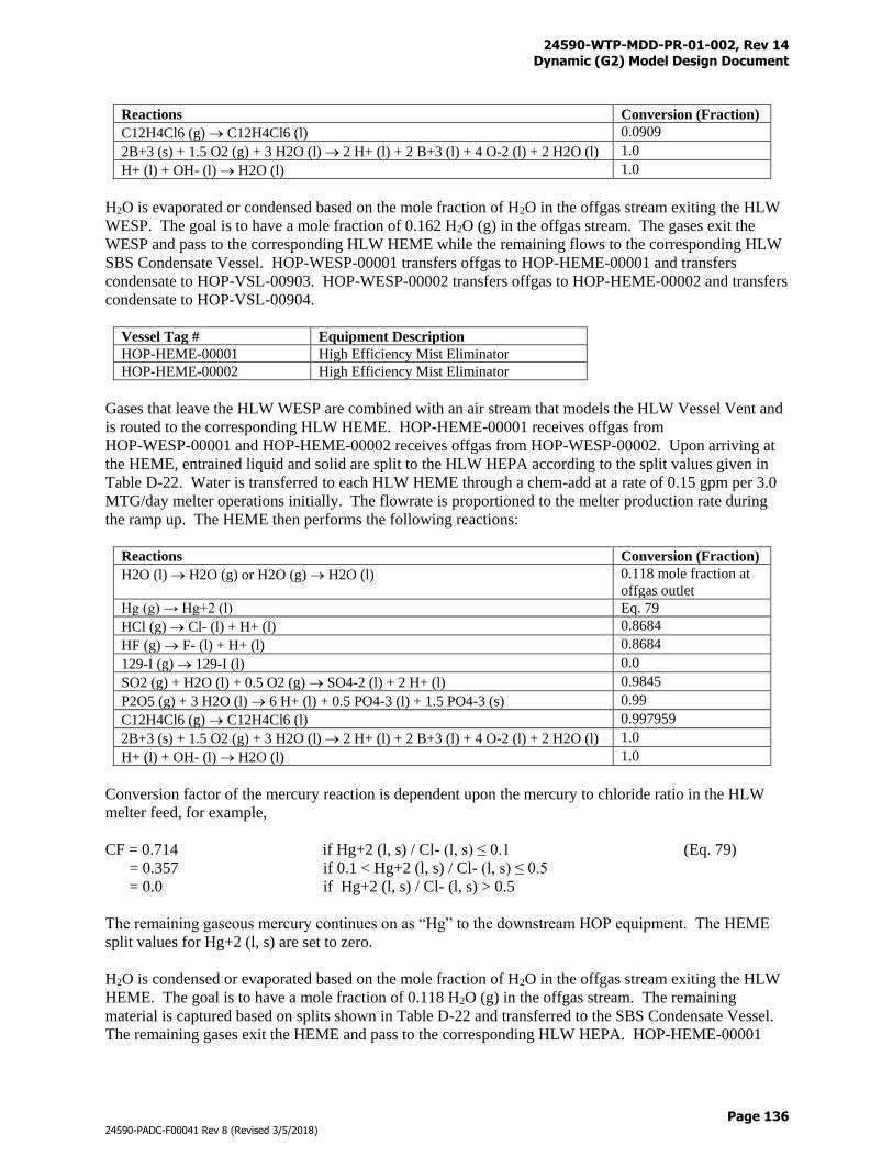
24590-WTP-MDD-PR-01-002, Rev 14 Dynamic (G2) Model Design Document
Page 136
24590-PADC-F00041 Rev 8 (Revised 3/5/2018)
Reactions Conversion (Fraction)
C12H4Cl6 (g) C12H4Cl6 (l) 0.0909
2B+3 (s) + 1.5 O2 (g) + 3 H2O (l) 2 H+ (l) + 2 B+3 (l) + 4 O-2 (l) + 2 H2O (l) 1.0
H+ (l) + OH- (l) H2O (l) 1.0
H2O is evaporated or condensed based on the mole fraction of H2O in the offgas stream exiting the HLW
WESP. The goal is to have a mole fraction of 0.162 H2O (g) in the offgas stream. The gases exit the
WESP and pass to the corresponding HLW HEME while the remaining flows to the corresponding HLW
SBS Condensate Vessel. HOP-WESP-00001 transfers offgas to HOP-HEME-00001 and transfers
condensate to HOP-VSL-00903. HOP-WESP-00002 transfers offgas to HOP-HEME-00002 and transfers
condensate to HOP-VSL-00904.
Vessel Tag # Equipment Description
HOP-HEME-00001 High Efficiency Mist Eliminator
HOP-HEME-00002 High Efficiency Mist Eliminator
Gases that leave the HLW WESP are combined with an air stream that models the HLW Vessel Vent and
is routed to the corresponding HLW HEME. HOP-HEME-00001 receives offgas from
HOP-WESP-00001 and HOP-HEME-00002 receives offgas from HOP-WESP-00002. Upon arriving at
the HEME, entrained liquid and solid are split to the HLW HEPA according to the split values given in
Table D-22. Water is transferred to each HLW HEME through a chem-add at a rate of 0.15 gpm per 3.0
MTG/day melter operations initially. The flowrate is proportioned to the melter production rate during
the ramp up. The HEME then performs the following reactions:
Reactions Conversion (Fraction)
H2O (l) H2O (g) or H2O (g) H2O (l) 0.118 mole fraction at
offgas outlet
Hg (g) → Hg+2 (l) Eq. 79
HCl (g) Cl- (l) + H+ (l) 0.8684
HF (g) F- (l) + H+ (l) 0.8684
129-I (g) 129-I (l) 0.0
SO2 (g) + H2O (l) + 0.5 O2 (g) SO4-2 (l) + 2 H+ (l) 0.9845
P2O5 (g) + 3 H2O (l) 6 H+ (l) + 0.5 PO4-3 (l) + 1.5 PO4-3 (s) 0.99
C12H4Cl6 (g) C12H4Cl6 (l) 0.997959
2B+3 (s) + 1.5 O2 (g) + 3 H2O (l) 2 H+ (l) + 2 B+3 (l) + 4 O-2 (l) + 2 H2O (l) 1.0
H+ (l) + OH- (l) H2O (l) 1.0
Conversion factor of the mercury reaction is dependent upon the mercury to chloride ratio in the HLW
melter feed, for example,
CF = 0.714 if Hg+2 (l, s) / Cl- (l, s) ≤ 0.1 (Eq. 79)
= 0.357 if 0.1 < Hg+2 (l, s) / Cl- (l, s) ≤ 0.5
= 0.0 if Hg+2 (l, s) / Cl- (l, s) > 0.5
The remaining gaseous mercury continues on as “Hg” to the downstream HOP equipment. The HEME
split values for Hg+2 (l, s) are set to zero.
H2O is condensed or evaporated based on the mole fraction of H2O in the offgas stream exiting the HLW
HEME. The goal is to have a mole fraction of 0.118 H2O (g) in the offgas stream. The remaining
material is captured based on splits shown in Table D-22 and transferred to the SBS Condensate Vessel.
The remaining gases exit the HEME and pass to the corresponding HLW HEPA. HOP-HEME-00001
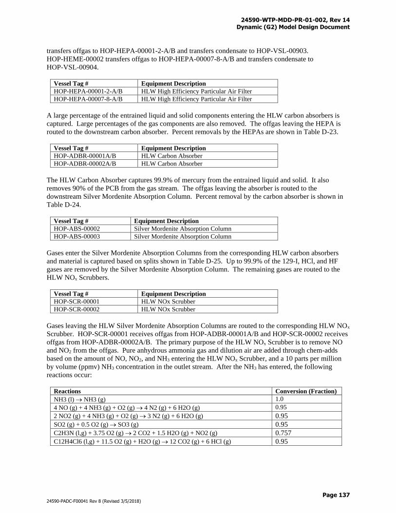
24590-WTP-MDD-PR-01-002, Rev 14 Dynamic (G2) Model Design Document
Page 137
24590-PADC-F00041 Rev 8 (Revised 3/5/2018)
transfers offgas to HOP-HEPA-00001-2-A/B and transfers condensate to HOP-VSL-00903.
HOP-HEME-00002 transfers offgas to HOP-HEPA-00007-8-A/B and transfers condensate to
HOP-VSL-00904.
Vessel Tag # Equipment Description
HOP-HEPA-00001-2-A/B HLW High Efficiency Particular Air Filter
HOP-HEPA-00007-8-A/B HLW High Efficiency Particular Air Filter
A large percentage of the entrained liquid and solid components entering the HLW carbon absorbers is
captured. Large percentages of the gas components are also removed. The offgas leaving the HEPA is
routed to the downstream carbon absorber. Percent removals by the HEPAs are shown in Table D-23.
Vessel Tag # Equipment Description
HOP-ADBR-00001A/B HLW Carbon Absorber
HOP-ADBR-00002A/B HLW Carbon Absorber
The HLW Carbon Absorber captures 99.9% of mercury from the entrained liquid and solid. It also
removes 90% of the PCB from the gas stream. The offgas leaving the absorber is routed to the
downstream Silver Mordenite Absorption Column. Percent removal by the carbon absorber is shown in
Table D-24.
Vessel Tag # Equipment Description
HOP-ABS-00002 Silver Mordenite Absorption Column
HOP-ABS-00003 Silver Mordenite Absorption Column
Gases enter the Silver Mordenite Absorption Columns from the corresponding HLW carbon absorbers
and material is captured based on splits shown in Table D-25. Up to 99.9% of the 129-I, HCl, and HF
gases are removed by the Silver Mordenite Absorption Column. The remaining gases are routed to the
HLW NOx Scrubbers.
Vessel Tag # Equipment Description
HOP-SCR-00001 HLW NOx Scrubber
HOP-SCR-00002 HLW NOx Scrubber
Gases leaving the HLW Silver Mordenite Absorption Columns are routed to the corresponding HLW NOx
Scrubber. HOP-SCR-00001 receives offgas from HOP-ADBR-00001A/B and HOP-SCR-00002 receives
offgas from HOP-ADBR-00002A/B. The primary purpose of the HLW NOx Scrubber is to remove NO
and NO2 from the offgas. Pure anhydrous ammonia gas and dilution air are added through chem-adds
based on the amount of NO, NO2, and NH3 entering the HLW NOx Scrubber, and a 10 parts per million
by volume (ppmv) NH3 concentration in the outlet stream. After the NH3 has entered, the following
reactions occur:
Reactions Conversion (Fraction)
NH3 (l) NH3 (g) 1.0
4 NO (g) + 4 NH3 (g) + O2 (g) 4 N2 (g) + 6 H2O (g) 0.95
2 NO2 (g) + 4 NH3 (g) + O2 (g) 3 N2 (g) + 6 H2O (g) 0.95
SO2 (g) + 0.5 O2 (g) SO3 (g) 0.95
C2H3N (l,g) + 3.75 O2 (g) 2 CO2 + 1.5 H2O (g) + NO2 (g) 0.757
C12H4Cl6 (l,g) + 11.5 O2 (g) + H2O (g) 12 CO2 (g) + 6 HCl (g) 0.95
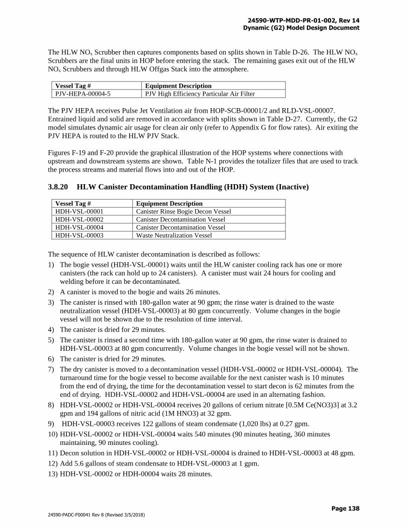
24590-WTP-MDD-PR-01-002, Rev 14 Dynamic (G2) Model Design Document
Page 138
24590-PADC-F00041 Rev 8 (Revised 3/5/2018)
The HLW NOx Scrubber then captures components based on splits shown in Table D-26. The HLW NOx
Scrubbers are the final units in HOP before entering the stack. The remaining gases exit out of the HLW
NOx Scrubbers and through HLW Offgas Stack into the atmosphere.
Vessel Tag # Equipment Description
PJV-HEPA-00004-5 PJV High Efficiency Particular Air Filter
The PJV HEPA receives Pulse Jet Ventilation air from HOP-SCB-00001/2 and RLD-VSL-00007.
Entrained liquid and solid are removed in accordance with splits shown in Table D-27. Currently, the G2
model simulates dynamic air usage for clean air only (refer to Appendix G for flow rates). Air exiting the
PJV HEPA is routed to the HLW PJV Stack.
Figures F-19 and F-20 provide the graphical illustration of the HOP systems where connections with
upstream and downstream systems are shown. Table N-1 provides the totalizer files that are used to track
the process streams and material flows into and out of the HOP.
3.8.20 HLW Canister Decontamination Handling (HDH) System (Inactive)
Vessel Tag # Equipment Description
HDH-VSL-00001 Canister Rinse Bogie Decon Vessel
HDH-VSL-00002 Canister Decontamination Vessel
HDH-VSL-00004 Canister Decontamination Vessel
HDH-VSL-00003 Waste Neutralization Vessel
The sequence of HLW canister decontamination is described as follows:
1) The bogie vessel (HDH-VSL-00001) waits until the HLW canister cooling rack has one or more
canisters (the rack can hold up to 24 canisters). A canister must wait 24 hours for cooling and
welding before it can be decontaminated.
2) A canister is moved to the bogie and waits 26 minutes.
3) The canister is rinsed with 180-gallon water at 90 gpm; the rinse water is drained to the waste
neutralization vessel (HDH-VSL-00003) at 80 gpm concurrently. Volume changes in the bogie
vessel will not be shown due to the resolution of time interval.
4) The canister is dried for 29 minutes.
5) The canister is rinsed a second time with 180-gallon water at 90 gpm, the rinse water is drained to
HDH-VSL-00003 at 80 gpm concurrently. Volume changes in the bogie vessel will not be shown.
6) The canister is dried for 29 minutes.
7) The dry canister is moved to a decontamination vessel (HDH-VSL-00002 or HDH-VSL-00004). The
turnaround time for the bogie vessel to become available for the next canister wash is 10 minutes
from the end of drying, the time for the decontamination vessel to start decon is 62 minutes from the
end of drying. HDH-VSL-00002 and HDH-VSL-00004 are used in an alternating fashion.
8) HDH-VSL-00002 or HDH-VSL-00004 receives 20 gallons of cerium nitrate [0.5M Ce(NO3)3] at 3.2
gpm and 194 gallons of nitric acid (1M HNO3) at 32 gpm.
9) HDH-VSL-00003 receives 122 gallons of steam condensate (1,020 lbs) at 0.27 gpm.
10) HDH-VSL-00002 or HDH-VSL-00004 waits 540 minutes (90 minutes heating, 360 minutes
maintaining, 90 minutes cooling).
11) Decon solution in HDH-VSL-00002 or HDH-VSL-00004 is drained to HDH-VSL-00003 at 48 gpm.
12) Add 5.6 gallons of steam condensate to HDH-VSL-00003 at 1 gpm.
13) HDH-VSL-00002 or HDH-00004 waits 28 minutes.
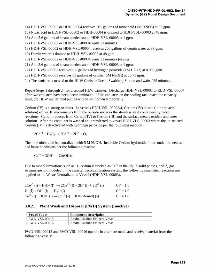
24590-WTP-MDD-PR-01-002, Rev 14 Dynamic (G2) Model Design Document
Page 139
24590-PADC-F00041 Rev 8 (Revised 3/5/2018)
14) HDH-VSL-00002 or HDH-00004 receives 201 gallons of nitric acid (1M HNO3) at 32 gpm.
15) Nitric acid in HDH-VSL-00002 or HDH-00004 is drained to HDH-VSL-00003 at 48 gpm.
16) Add 5.6 gallons of steam condensate to HDH-VSL-00003 at 1 gpm.
17) HDH-VSL-00002 or HDH-VSL-00004 waits 21 minutes.
18) HDH-VSL-00002 or HDH-VSL-00004 receives 200 gallons of demin water at 33 gpm.
19) Demin water is drained to HDH-VSL-00003 at 48 gpm.
20) HDH-VSL-00002 or HDH-VSL-00004 waits 31 minutes (drying).
21) Add 5.6 gallons of steam condensate to HDH-VSL-00003 at 1 gpm.
22) HDH-VSL-00003 receives 0.5 gallons of hydrogen peroxide (1M H2O2) at 0.033 gpm.
23) HDH-VSL-00003 receives 83 gallons of caustic (5M NaOH) at 20.75 gpm.
24) The canister is moved to the HLW Canister Decon Swabbing Station and waits 235 minutes.
Repeat Steps 1 through 24 for a second HLW canister. Discharge HDH-VSL-00003 to RLD-VSL-00007
after two canisters have been decontaminated. If the canisters on the cooling rack reach the capacity
limit, the HLW melter feed pumps will be shut down temporarily.
Cerium (IV) is a strong oxidizer. In vessels HDH-VSL-00002/4, Cerium (IV) nitrate (in nitric acid
solution) etches 10 micrometers from the outside surfaces the stainless steel containers by redox
reactions. Cerium reduces from Cerium(IV) to Cerium (III) and the surface metals oxidize and enter
solution. After the container is washed and transferred to vessel HDH-VLS-00003 where the un-reacted
Cerium (IV) is deactivated with hydrogen peroxide per the following reaction:
2Ce+4 + H2O2 → 2Ce+3 + 2H+ + O2
Then the nitric acid is neutralized with 5 M NaOH. Insoluble Cerium hydroxide forms under the neutral
and basic conditions per the following reaction:
Ce+3 + 3OH- → Ce(OH)3↓
Due to model limitations such as: 1) cerium is tracked as Ce+3 in the liquid/solid phases, and 2) gas
streams are not modeled in the canister decontamination system, the following simplified reactions are
applied to the Waste Neutralization Vessel (HDH-VSL-00003).
2Ce+3 (l) + H2O2 (l) → 2Ce+3 (l) + 2H+ (l) + 2O-2 (l) CF = 1.0
H+ (l) + OH- (l) → H2O (l) CF = 1.0
Ce+3 (l) + 3OH- (l) → Ce+3 (s) + 3OH(Bound) (s) CF = 1.0
3.8.21 Plant Wash and Disposal (PWD) System (Inactive)
Vessel Tag # Equipment Description
PWD-VSL-00015 Acidic/Alkaline Effluent Vessel
PWD-VSL-00016 Acidic/Alkaline Effluent Vessel
PWD-VSL-00015 and PWD-VSL-00016 operate in alternate mode and receive material from the
following vessels:
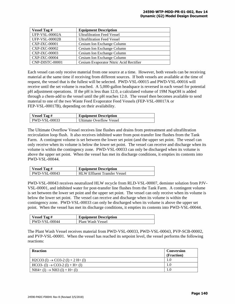
24590-WTP-MDD-PR-01-002, Rev 14 Dynamic (G2) Model Design Document
Page 140
24590-PADC-F00041 Rev 8 (Revised 3/5/2018)
Vessel Tag # Equipment Description
UFP-VSL-00002A Ultrafiltration Feed Vessel
UFP-VSL-00002B Ultrafiltration Feed Vessel
CXP-IXC-00001 Cesium Ion Exchange Column
CXP-IXC-00002 Cesium Ion Exchange Column
CXP-IXC-00003 Cesium Ion Exchange Column
CXP-IXC-00004 Cesium Ion Exchange Column
CNP-DISTC-00001 Cesium Evaporator Nitric Acid Rectifier
Each vessel can only receive material from one source at a time. However, both vessels can be receiving
material at the same time if receiving from different sources. If both vessels are available at the time of
request, the vessel that is the fullest will be selected. PWD-VSL-00015 and PWD-VSL-00016 will
receive until the set volume is reached. A 5,000-gallon headspace is reversed in each vessel for potential
pH adjustment operations. If the pH is less than 12.0, a calculated volume of 19M NapOH is added
through a chem-add to the vessel until the pH reaches 12.0. The vessel then becomes available to send
material to one of the two Waste Feed Evaporator Feed Vessels (FEP-VSL-00017A or
FEP-VSL-00017B), depending on their availability.
Vessel Tag # Equipment Description
PWD-VSL-00033 Ultimate Overflow Vessel
The Ultimate Overflow Vessel receives line flushes and drains from pretreatment and ultrafiltration
recirculation loop flush. It also receives inhibited water from post-transfer line flushes from the Tank
Farm. A contingent volume is set between the lower set point (and the upper set point. The vessel can
only receive when its volume is below the lower set point. The vessel can receive and discharge when its
volume is within the contingency zone. PWD-VSL-00033 can only be discharged when its volume is
above the upper set point. When the vessel has met its discharge conditions, it empties its contents into
PWD-VSL-00044.
Vessel Tag # Equipment Description
PWD-VSL-00043 HLW Effluent Transfer Vessel
PWD-VSL-00043 receives neutralized HLW recycle from RLD-VSL-00007, demister solution from PJV-
VSL-00001, and inhibited water for post-transfer line flushes from the Tank Farm. A contingent volume
is set between the lower set point and the upper set point. The vessel can only receive when its volume is
below the lower set point. The vessel can receive and discharge when its volume is within the
contingency zone. PWD-VSL-00033 can only be discharged when its volume is above the upper set
point. When the vessel has met its discharge conditions, it empties its contents into PWD-VSL-00044.
Vessel Tag # Equipment Description
PWD-VSL-00044 Plant Wash Vessel
The Plant Wash Vessel receives material from PWD-VSL-00033, PWD-VSL-00043, PVP-SCB-00002,
and PVP-VSL-00001. When the vessel has reached its setpoint level, the vessel performs the following
reactions:
Reaction Conversion
(Fraction)
H2CO3 (l) CO3-2 (l) + 2 H+ (l) 1.0
HCO3- (l) CO3-2 (l) + H+ (l) 1.0
NH4+ (l) NH3 (l) + H+ (l) 1.0
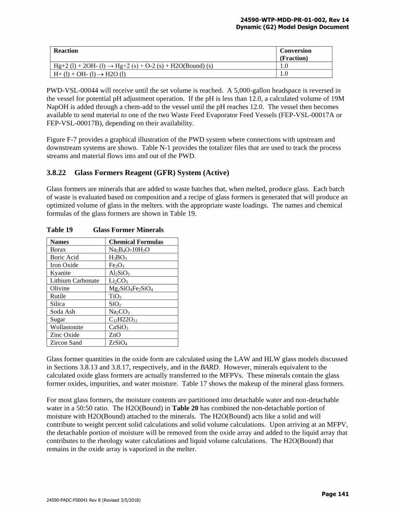
24590-WTP-MDD-PR-01-002, Rev 14 Dynamic (G2) Model Design Document
Page 141
24590-PADC-F00041 Rev 8 (Revised 3/5/2018)
Reaction Conversion
(Fraction)
Hg+2 (l) + 2OH- (l) → Hg+2 (s) + O-2 (s) + H2O(Bound) (s) 1.0
H+ (l) + OH- (l) H2O (l) 1.0
PWD-VSL-00044 will receive until the set volume is reached. A 5,000-gallon headspace is reversed in
the vessel for potential pH adjustment operation. If the pH is less than 12.0, a calculated volume of 19M
NapOH is added through a chem-add to the vessel until the pH reaches 12.0. The vessel then becomes
available to send material to one of the two Waste Feed Evaporator Feed Vessels (FEP-VSL-00017A or
FEP-VSL-00017B), depending on their availability.
Figure F-7 provides a graphical illustration of the PWD system where connections with upstream and
downstream systems are shown. Table N-1 provides the totalizer files that are used to track the process
streams and material flows into and out of the PWD.
3.8.22 Glass Formers Reagent (GFR) System (Active)
Glass formers are minerals that are added to waste batches that, when melted, produce glass. Each batch
of waste is evaluated based on composition and a recipe of glass formers is generated that will produce an
optimized volume of glass in the melters. with the appropriate waste loadings. The names and chemical
formulas of the glass formers are shown in Table 19.
Table 19 Glass Former Minerals
Names Chemical Formulas
Borax Na2B4O710H2O
Boric Acid H3BO3
Iron Oxide Fe2O3
Kyanite Al2SiO5
Lithium Carbonate Li2CO3
Olivine Mg2SiO4Fe2SiO4
Rutile TiO2
Silica SiO2
Soda Ash Na2CO3
Sugar C12H22O11
Wollastonite CaSiO3
Zinc Oxide ZnO
Zircon Sand ZrSiO4
Glass former quantities in the oxide form are calculated using the LAW and HLW glass models discussed
in Sections 3.8.13 and 3.8.17, respectively, and in the BARD. However, minerals equivalent to the
calculated oxide glass formers are actually transferred to the MFPVs. These minerals contain the glass
former oxides, impurities, and water moisture. Table 17 shows the makeup of the mineral glass formers.
For most glass formers, the moisture contents are partitioned into detachable water and non-detachable
water in a 50:50 ratio. The H2O(Bound) in Table 20 has combined the non-detachable portion of
moisture with H2O(Bound) attached to the minerals. The H2O(Bound) acts like a solid and will
contribute to weight percent solid calculations and solid volume calculations. Upon arriving at an MFPV,
the detachable portion of moisture will be removed from the oxide array and added to the liquid array that
contributes to the rheology water calculations and liquid volume calculations. The H2O(Bound) that
remains in the oxide array is vaporized in the melter.
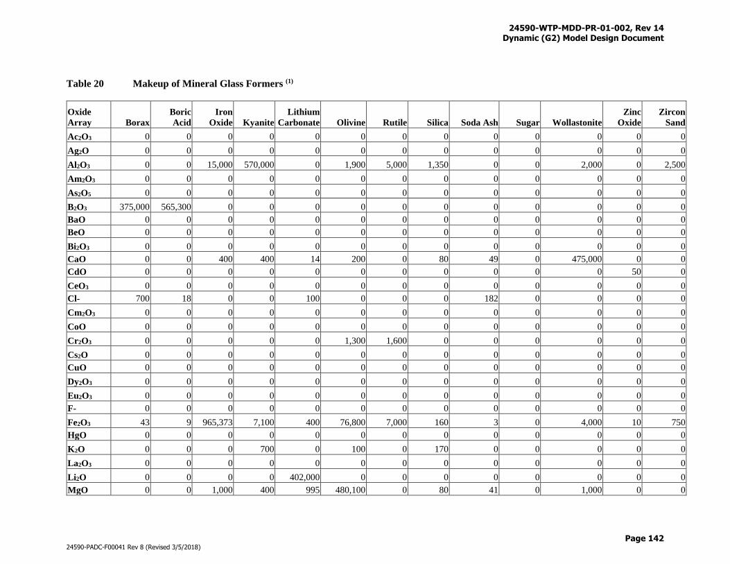
24590-WTP-MDD-PR-01-002, Rev 14 Dynamic (G2) Model Design Document
Page 142
24590-PADC-F00041 Rev 8 (Revised 3/5/2018)
Table 20 Makeup of Mineral Glass Formers (1)
Oxide
Array Borax
Boric
Acid
Iron
Oxide Kyanite
Lithium
Carbonate Olivine Rutile Silica Soda Ash Sugar Wollastonite
Zinc
Oxide
Zircon
Sand
Ac2O3 0 0 0 0 0 0 0 0 0 0 0 0 0
Ag2O 0 0 0 0 0 0 0 0 0 0 0 0 0
Al2O3 0 0 15,000 570,000 0 1,900 5,000 1,350 0 0 2,000 0 2,500
Am2O3 0 0 0 0 0 0 0 0 0 0 0 0 0
As2O5 0 0 0 0 0 0 0 0 0 0 0 0 0
B2O3 375,000 565,300 0 0 0 0 0 0 0 0 0 0 0
BaO 0 0 0 0 0 0 0 0 0 0 0 0 0
BeO 0 0 0 0 0 0 0 0 0 0 0 0 0
Bi2O3 0 0 0 0 0 0 0 0 0 0 0 0 0
CaO 0 0 400 400 14 200 0 80 49 0 475,000 0 0
CdO 0 0 0 0 0 0 0 0 0 0 0 50 0
CeO3 0 0 0 0 0 0 0 0 0 0 0 0 0
Cl- 700 18 0 0 100 0 0 0 182 0 0 0 0
Cm2O3 0 0 0 0 0 0 0 0 0 0 0 0 0
CoO 0 0 0 0 0 0 0 0 0 0 0 0 0
Cr2O3 0 0 0 0 0 1,300 1,600 0 0 0 0 0 0
Cs2O 0 0 0 0 0 0 0 0 0 0 0 0 0
CuO 0 0 0 0 0 0 0 0 0 0 0 0 0
Dy2O3 0 0 0 0 0 0 0 0 0 0 0 0 0
Eu2O3 0 0 0 0 0 0 0 0 0 0 0 0 0
F- 0 0 0 0 0 0 0 0 0 0 0 0 0
Fe2O3 43 9 965,373 7,100 400 76,800 7,000 160 3 0 4,000 10 750
HgO 0 0 0 0 0 0 0 0 0 0 0 0 0
K2O 0 0 0 700 0 100 0 170 0 0 0 0 0
La2O3 0 0 0 0 0 0 0 0 0 0 0 0 0
Li2O 0 0 0 0 402,000 0 0 0 0 0 0 0 0
MgO 0 0 1,000 400 995 480,100 0 80 41 0 1,000 0 0
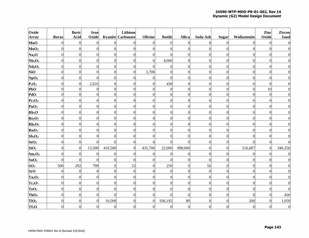
24590-WTP-MDD-PR-01-002, Rev 14 Dynamic (G2) Model Design Document
Page 143
24590-PADC-F00041 Rev 8 (Revised 3/5/2018)
Oxide
Array Borax
Boric
Acid
Iron
Oxide Kyanite
Lithium
Carbonate Olivine Rutile Silica Soda Ash Sugar Wollastonite
Zinc
Oxide
Zircon
Sand
MnO 0 0 0 0 0 0 0 0 0 0 0 0 0
MoO3 0 0 0 0 0 0 0 0 0 0 0 0 0
Na2O 0 0 0 0 0 0 0 0 0 0 0 0 0
Nb2O5 0 0 0 0 0 0 4,000 0 0 0 0 0 0
Nd2O3 0 0 0 0 0 0 0 0 0 0 0 0 0
NiO 0 0 0 0 0 3,700 0 0 0 0 0 0 0
NpO2 0 0 0 0 0 0 0 0 0 0 0 0 0
P2O5 0 0 2,635 0 0 0 458 0 0 0 0 0 0
PbO 0 0 0 0 0 0 0 0 0 0 0 10 0
PdO 0 0 0 0 0 0 0 0 0 0 0 0 0
Pr2O3 0 0 0 0 0 0 0 0 0 0 0 0 0
PuO2 0 0 0 0 0 0 0 0 0 0 0 0 0
Rb2O 0 0 0 0 0 0 0 0 0 0 0 0 0
Re2O7 0 0 0 0 0 0 0 0 0 0 0 0 0
Rh2O3 0 0 0 0 0 0 0 0 0 0 0 0 0
RuO2 0 0 0 0 0 0 0 0 0 0 0 0 0
Sb2O3 0 0 0 0 0 0 0 0 0 0 0 0 0
SeO2 0 0 0 0 0 0 0 0 0 0 0 0 0
SiO2 0 0 13,500 410,500 0 435,700 22,000 998,060 0 0 516,687 0 340,250
Sm2O3 0 0 0 0 0 0 0 0 0 0 0 0 0
SnO2 0 0 0 0 0 0 0 0 0 0 0 0 0
SO3 500 292 799 0 33 0 250 0 56 0 0 0 0
SrO 0 0 0 0 0 0 0 0 0 0 0 0 0
Ta2O5 0 0 0 0 0 0 0 0 0 0 0 0 0
Tc2O7 0 0 0 0 0 0 0 0 0 0 0 0 0
TeO2 0 0 0 0 0 0 0 0 0 0 0 0 0
ThO2 0 0 0 0 0 0 0 0 0 0 0 0 450
TiO2 0 0 0 10,500 0 0 936,192 80 0 0 200 0 1,050
TI2O 0 0 0 0 0 0 0 0 0 0 0 0 0
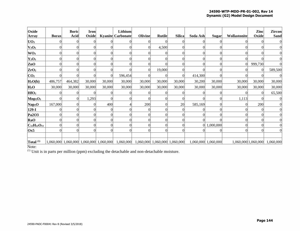
24590-WTP-MDD-PR-01-002, Rev 14 Dynamic (G2) Model Design Document
Page 144
24590-PADC-F00041 Rev 8 (Revised 3/5/2018)
Oxide
Array Borax
Boric
Acid
Iron
Oxide Kyanite
Lithium
Carbonate Olivine Rutile Silica Soda Ash Sugar Wollastonite
Zinc
Oxide
Zircon
Sand
UO3 0 0 0 0 0 0 0 0 0 0 0 0 0
V2O5 0 0 0 0 0 0 4,500 0 0 0 0 0 0
WO3 0 0 0 0 0 0 0 0 0 0 0 0 0
Y2O3 0 0 0 0 0 0 0 0 0 0 0 0 0
ZnO 0 0 0 0 0 0 0 0 0 0 0 999,730 0
ZrO2 0 0 0 0 0 0 19,000 0 0 0 0 0 589,500
CO2 0 0 0 0 596,454 0 0 0 414,300 0 0 0 0
H2O(b) 486,757 464,382 30,000 30,000 30,000 30,000 30,000 30,000 30,200 30,000 30,000 30,000 30,000
H2O 30,000 30,000 30,000 30,000 30,000 30,000 30,000 30,000 30,000 30,000 30,000 30,000 30,000
HfO2 0 0 0 0 0 0 0 0 0 0 0 0 65,500
Mnp2O3 0 0 1,293 0 0 0 0 0 0 0 1,113 0 0
Nap2O 167,000 0 0 400 4 200 0 20 585,169 0 0 200 0
129-I 0 0 0 0 0 0 0 0 0 0 0 0 0
Pa2O3 0 0 0 0 0 0 0 0 0 0 0 0 0
RaO 0 0 0 0 0 0 0 0 0 0 0 0 0
C12H22O11 0 0 0 0 0 0 0 0 0 1,000,000 0 0 0
Ox5 0 0 0 0 0 0 0 0 0 0 0 0 0
Total (1) 1,060,000 1,060,000 1,060,000 1,060,000 1,060,000 1,060,000 1,060,000 1,060,000 1,060,000 1,060,000 1,060,000 1,060,000 1,060,000
Note: (1) Unit is in parts per million (ppm) excluding the detachable and non-detachable moisture.
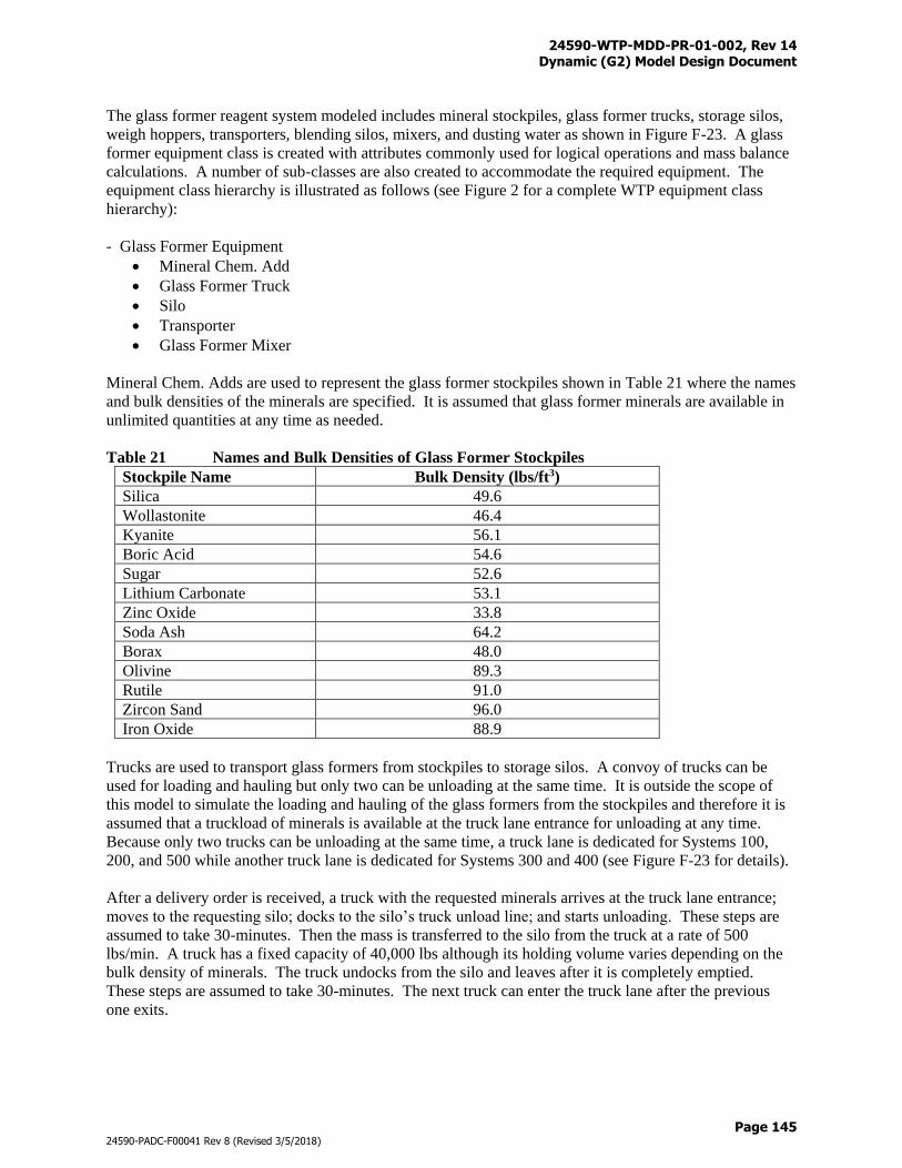
24590-WTP-MDD-PR-01-002, Rev 14 Dynamic (G2) Model Design Document
Page 145
24590-PADC-F00041 Rev 8 (Revised 3/5/2018)
The glass former reagent system modeled includes mineral stockpiles, glass former trucks, storage silos,
weigh hoppers, transporters, blending silos, mixers, and dusting water as shown in Figure F-23. A glass
former equipment class is created with attributes commonly used for logical operations and mass balance
calculations. A number of sub-classes are also created to accommodate the required equipment. The
equipment class hierarchy is illustrated as follows (see Figure 2 for a complete WTP equipment class
hierarchy):
- Glass Former Equipment
Mineral Chem. Add
Glass Former Truck
Silo
Transporter
Glass Former Mixer
Mineral Chem. Adds are used to represent the glass former stockpiles shown in Table 21 where the names
and bulk densities of the minerals are specified. It is assumed that glass former minerals are available in
unlimited quantities at any time as needed.
Table 21 Names and Bulk Densities of Glass Former Stockpiles
Stockpile Name Bulk Density (lbs/ft3)
Silica 49.6
Wollastonite 46.4
Kyanite 56.1
Boric Acid 54.6
Sugar 52.6
Lithium Carbonate 53.1
Zinc Oxide 33.8
Soda Ash 64.2
Borax 48.0
Olivine 89.3
Rutile 91.0
Zircon Sand 96.0
Iron Oxide 88.9
Trucks are used to transport glass formers from stockpiles to storage silos. A convoy of trucks can be
used for loading and hauling but only two can be unloading at the same time. It is outside the scope of
this model to simulate the loading and hauling of the glass formers from the stockpiles and therefore it is
assumed that a truckload of minerals is available at the truck lane entrance for unloading at any time.
Because only two trucks can be unloading at the same time, a truck lane is dedicated for Systems 100,
200, and 500 while another truck lane is dedicated for Systems 300 and 400 (see Figure F-23 for details).
After a delivery order is received, a truck with the requested minerals arrives at the truck lane entrance;
moves to the requesting silo; docks to the silo’s truck unload line; and starts unloading. These steps are
assumed to take 30-minutes. Then the mass is transferred to the silo from the truck at a rate of 500
lbs/min. A truck has a fixed capacity of 40,000 lbs although its holding volume varies depending on the
bulk density of minerals. The truck undocks from the silo and leaves after it is completely emptied.
These steps are assumed to take 30-minutes. The next truck can enter the truck lane after the previous
one exits.
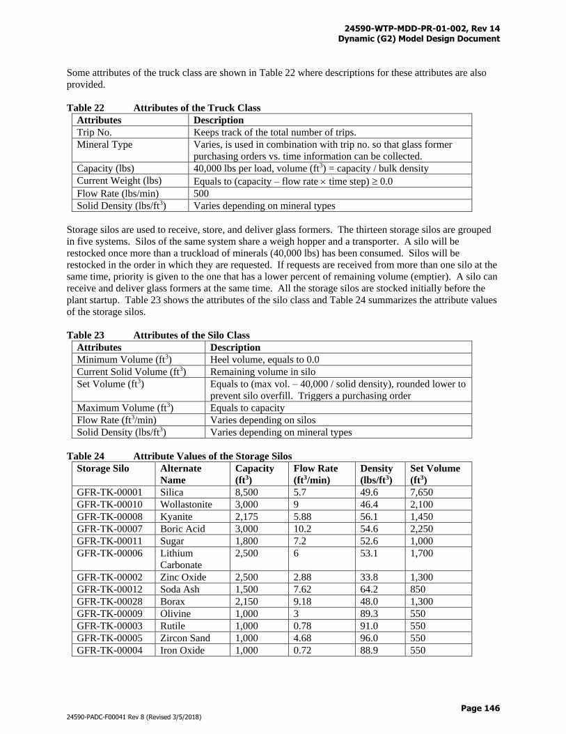
24590-WTP-MDD-PR-01-002, Rev 14 Dynamic (G2) Model Design Document
Page 146
24590-PADC-F00041 Rev 8 (Revised 3/5/2018)
Some attributes of the truck class are shown in Table 22 where descriptions for these attributes are also
provided.
Table 22 Attributes of the Truck Class
Attributes Description
Trip No. Keeps track of the total number of trips.
Mineral Type Varies, is used in combination with trip no. so that glass former
purchasing orders vs. time information can be collected.
Capacity (lbs) 40,000 lbs per load, volume (ft3) = capacity / bulk density
Current Weight (lbs) Equals to (capacity – flow rate time step) 0.0
Flow Rate (lbs/min) 500
Solid Density (lbs/ft3) Varies depending on mineral types
Storage silos are used to receive, store, and deliver glass formers. The thirteen storage silos are grouped
in five systems. Silos of the same system share a weigh hopper and a transporter. A silo will be
restocked once more than a truckload of minerals (40,000 lbs) has been consumed. Silos will be
restocked in the order in which they are requested. If requests are received from more than one silo at the
same time, priority is given to the one that has a lower percent of remaining volume (emptier). A silo can
receive and deliver glass formers at the same time. All the storage silos are stocked initially before the
plant startup. Table 23 shows the attributes of the silo class and Table 24 summarizes the attribute values
of the storage silos.
Table 23 Attributes of the Silo Class
Attributes Description
Minimum Volume (ft3) Heel volume, equals to 0.0
Current Solid Volume (ft3) Remaining volume in silo
Set Volume (ft3) Equals to (max vol. – 40,000 / solid density), rounded lower to
prevent silo overfill. Triggers a purchasing order
Maximum Volume (ft3) Equals to capacity
Flow Rate (ft3/min) Varies depending on silos
Solid Density (lbs/ft3) Varies depending on mineral types
Table 24 Attribute Values of the Storage Silos
Storage Silo Alternate
Name
Capacity
(ft3)
Flow Rate
(ft3/min)
Density
(lbs/ft3)
Set Volume
(ft3)
GFR-TK-00001 Silica 8,500 5.7 49.6 7,650
GFR-TK-00010 Wollastonite 3,000 9 46.4 2,100
GFR-TK-00008 Kyanite 2,175 5.88 56.1 1,450
GFR-TK-00007 Boric Acid 3,000 10.2 54.6 2,250
GFR-TK-00011 Sugar 1,800 7.2 52.6 1,000
GFR-TK-00006 Lithium
Carbonate
2,500 6 53.1 1,700
GFR-TK-00002 Zinc Oxide 2,500 2.88 33.8 1,300
GFR-TK-00012 Soda Ash 1,500 7.62 64.2 850
GFR-TK-00028 Borax 2,150 9.18 48.0 1,300
GFR-TK-00009 Olivine 1,000 3 89.3 550
GFR-TK-00003 Rutile 1,000 0.78 91.0 550
GFR-TK-00005 Zircon Sand 1,000 4.68 96.0 550
GFR-TK-00004 Iron Oxide 1,000 0.72 88.9 550
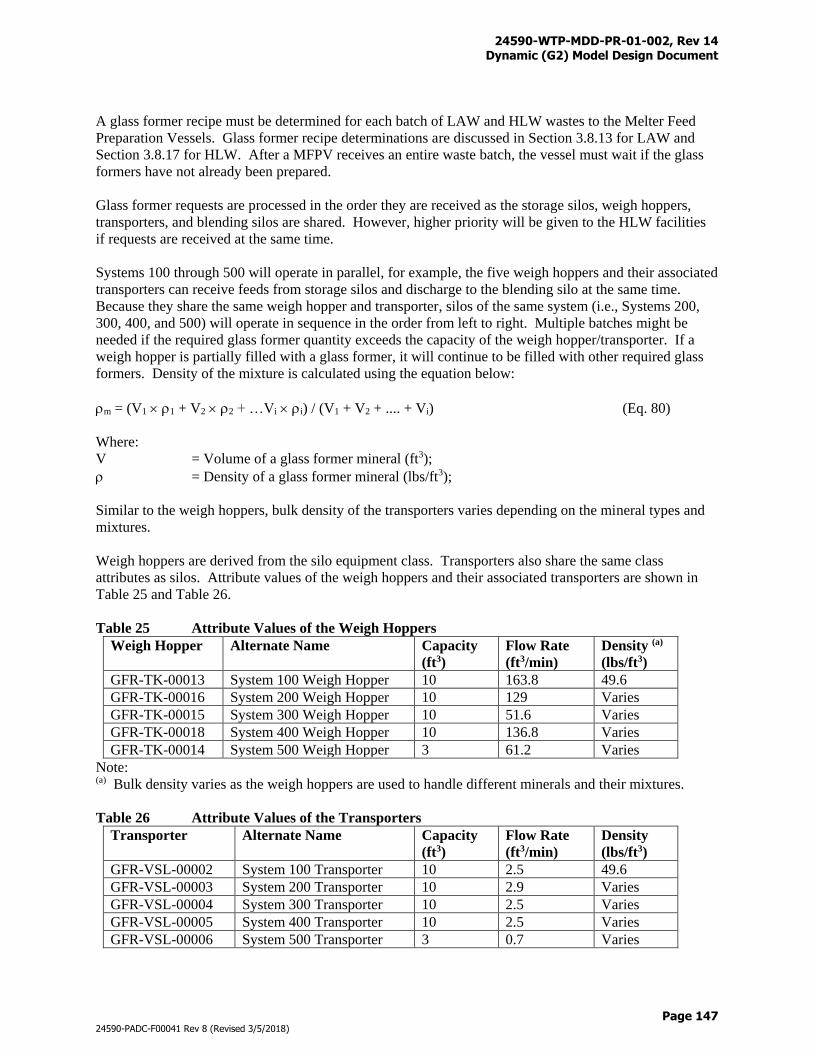
24590-WTP-MDD-PR-01-002, Rev 14 Dynamic (G2) Model Design Document
Page 147
24590-PADC-F00041 Rev 8 (Revised 3/5/2018)
A glass former recipe must be determined for each batch of LAW and HLW wastes to the Melter Feed
Preparation Vessels. Glass former recipe determinations are discussed in Section 3.8.13 for LAW and
Section 3.8.17 for HLW. After a MFPV receives an entire waste batch, the vessel must wait if the glass
formers have not already been prepared.
Glass former requests are processed in the order they are received as the storage silos, weigh hoppers,
transporters, and blending silos are shared. However, higher priority will be given to the HLW facilities
if requests are received at the same time.
Systems 100 through 500 will operate in parallel, for example, the five weigh hoppers and their associated
transporters can receive feeds from storage silos and discharge to the blending silo at the same time.
Because they share the same weigh hopper and transporter, silos of the same system (i.e., Systems 200,
300, 400, and 500) will operate in sequence in the order from left to right. Multiple batches might be
needed if the required glass former quantity exceeds the capacity of the weigh hopper/transporter. If a
weigh hopper is partially filled with a glass former, it will continue to be filled with other required glass
formers. Density of the mixture is calculated using the equation below:
m = (V1 1 + V2 2 + …Vi i) / (V1 + V2 + .... + Vi) (Eq. 80)
Where:
V = Volume of a glass former mineral (ft3);
= Density of a glass former mineral (lbs/ft3);
Similar to the weigh hoppers, bulk density of the transporters varies depending on the mineral types and
mixtures.
Weigh hoppers are derived from the silo equipment class. Transporters also share the same class
attributes as silos. Attribute values of the weigh hoppers and their associated transporters are shown in
Table 25 and Table 26.
Table 25 Attribute Values of the Weigh Hoppers
Weigh Hopper Alternate Name Capacity
(ft3)
Flow Rate
(ft3/min)
Density (a)
(lbs/ft3)
GFR-TK-00013 System 100 Weigh Hopper 10 163.8 49.6
GFR-TK-00016 System 200 Weigh Hopper 10 129 Varies
GFR-TK-00015 System 300 Weigh Hopper 10 51.6 Varies
GFR-TK-00018 System 400 Weigh Hopper 10 136.8 Varies
GFR-TK-00014 System 500 Weigh Hopper 3 61.2 Varies
Note: (a) Bulk density varies as the weigh hoppers are used to handle different minerals and their mixtures.
Table 26 Attribute Values of the Transporters
Transporter Alternate Name Capacity
(ft3)
Flow Rate
(ft3/min)
Density
(lbs/ft3)
GFR-VSL-00002 System 100 Transporter 10 2.5 49.6
GFR-VSL-00003 System 200 Transporter 10 2.9 Varies
GFR-VSL-00004 System 300 Transporter 10 2.5 Varies
GFR-VSL-00005 System 400 Transporter 10 2.5 Varies
GFR-VSL-00006 System 500 Transporter 3 0.7 Varies
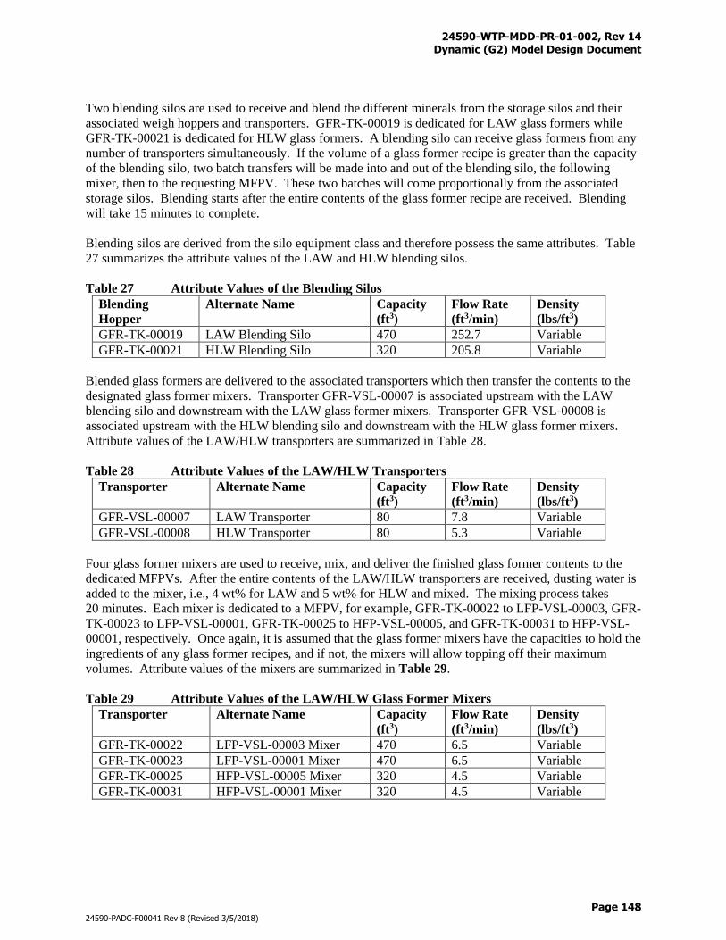
24590-WTP-MDD-PR-01-002, Rev 14 Dynamic (G2) Model Design Document
Page 148
24590-PADC-F00041 Rev 8 (Revised 3/5/2018)
Two blending silos are used to receive and blend the different minerals from the storage silos and their
associated weigh hoppers and transporters. GFR-TK-00019 is dedicated for LAW glass formers while
GFR-TK-00021 is dedicated for HLW glass formers. A blending silo can receive glass formers from any
number of transporters simultaneously. If the volume of a glass former recipe is greater than the capacity
of the blending silo, two batch transfers will be made into and out of the blending silo, the following
mixer, then to the requesting MFPV. These two batches will come proportionally from the associated
storage silos. Blending starts after the entire contents of the glass former recipe are received. Blending
will take 15 minutes to complete.
Blending silos are derived from the silo equipment class and therefore possess the same attributes. Table
27 summarizes the attribute values of the LAW and HLW blending silos.
Table 27 Attribute Values of the Blending Silos
Blending
Hopper
Alternate Name Capacity
(ft3)
Flow Rate
(ft3/min)
Density
(lbs/ft3)
GFR-TK-00019 LAW Blending Silo 470 252.7 Variable
GFR-TK-00021 HLW Blending Silo 320 205.8 Variable
Blended glass formers are delivered to the associated transporters which then transfer the contents to the
designated glass former mixers. Transporter GFR-VSL-00007 is associated upstream with the LAW
blending silo and downstream with the LAW glass former mixers. Transporter GFR-VSL-00008 is
associated upstream with the HLW blending silo and downstream with the HLW glass former mixers.
Attribute values of the LAW/HLW transporters are summarized in Table 28.
Table 28 Attribute Values of the LAW/HLW Transporters
Transporter Alternate Name Capacity
(ft3)
Flow Rate
(ft3/min)
Density
(lbs/ft3)
GFR-VSL-00007 LAW Transporter 80 7.8 Variable
GFR-VSL-00008 HLW Transporter 80 5.3 Variable
Four glass former mixers are used to receive, mix, and deliver the finished glass former contents to the
dedicated MFPVs. After the entire contents of the LAW/HLW transporters are received, dusting water is
added to the mixer, i.e., 4 wt% for LAW and 5 wt% for HLW and mixed. The mixing process takes
20 minutes. Each mixer is dedicated to a MFPV, for example, GFR-TK-00022 to LFP-VSL-00003, GFR-
TK-00023 to LFP-VSL-00001, GFR-TK-00025 to HFP-VSL-00005, and GFR-TK-00031 to HFP-VSL-
00001, respectively. Once again, it is assumed that the glass former mixers have the capacities to hold the
ingredients of any glass former recipes, and if not, the mixers will allow topping off their maximum
volumes. Attribute values of the mixers are summarized in Table 29.
Table 29 Attribute Values of the LAW/HLW Glass Former Mixers
Transporter Alternate Name Capacity
(ft3)
Flow Rate
(ft3/min)
Density
(lbs/ft3)
GFR-TK-00022 LFP-VSL-00003 Mixer 470 6.5 Variable
GFR-TK-00023 LFP-VSL-00001 Mixer 470 6.5 Variable
GFR-TK-00025 HFP-VSL-00005 Mixer 320 4.5 Variable
GFR-TK-00031 HFP-VSL-00001 Mixer 320 4.5 Variable
24590-WTP-MDD-PR-01-002, Rev 14 Dynamic (G2) Model Design Document
Page 149
24590-PADC-F00041 Rev 8 (Revised 3/5/2018)
Figure F-23 provides a graphical illustration of the GFR system where connections with upstream and
downstream systems are shown. Table N-1 provides the totalizer files that are used to track the process
streams and material flows into and out of the GFR.
3.8.23 Supplemental LAW Facility (Inactive)
For purposes of a conceptual design, the WTP excess treated LAW will be processed by a Supplemental
LAW (SLAW) facility, located in the 200 East Area. The SLAW facility is presently assumed to be
another vitrification facility with the same technical design, glass chemistry, melters, and similar feed and
offgas equipment as the WTP LAW vitrification facility.
Nomenclature
Equipment in the SLAW vitrification facility are similar to the existing WTP LAW vitrification facility,
therefore, the same equipment and line designations are used except that a suffix “S-” to the label is added
to indicate supplemental LAW. For example, the first melter in the SLAW vitrification facility becomes
S-LMP-01. Likewise, glass made by the SLAW vitrification facility, etc., is designated with an “S-” (i.e.,
S-ILAW or S-LAW glass).
Equipment
The SLAW vitrification facility receives excess treated LAW from the WTP PT Facility at the junction
presently designated LCP-VSL-00001 (see Section 3.7.14 for details). The schematic and arrangement of
equipment in the SLAW vitrification facility is shown in Figure F-27.
One large 360,000 gal LAW collection vessel (designated S-LCV) receives excess treated LAW feed
from the WTP and feeds the SLAW vitrification facility.
An evaporator and holding vessel at the back-end of the SLAW vitrification facility are used to
concentrate condensate from a submerged bed scrubber (designated S-SBS, size 6xWTP) with a S-SBS
condensate collection vessel (S-CCV-1, size 6xWTP) and a wet electrostatic precipitator (designated S-
WESP, size 6xWTP). No other equipment past the S-WESP are modeled at this time. The resulting
concentrated condensate is recycled to the SLAW vitrification evaporator holding vessel (S-CVV-2) and
the evaporator (designated S-EVAP). The evaporator has a boil-off capacity of 30 gal/min. Evaporator
bottoms are sent to S-LCV and evaporator overheads are sent to LERF/ETF.
There are six LAW type melters (designated S-LMP-01,-02,-03, -04, -05, and -06). With each having 15
metric ton/day glass production capacity. Each melter has its own melter feed preparation vessel
(designated S-LEP-01, -03, -05, -07, -09) and its own feed vessel (designated S-LEP-01, -02, -03, -04, -
05, and -06). Likewise, each melter has its own film cooler (designated S-LMP-MLTR-01, -02, -03, -04,
-05, and -06-AIR/WATER) that delivers its cooled offgas to the submerged bed scrubber (S-SBS). Air
inflows, etc., to the melters, film coolers, etc., are the same be the same with the WTP’s equipment.
Operation
Melter S-LMP-01 will come on line first to try and meet the SLAW vitrification facility’s demand. If the
capacity of Melter S-LMP-01 is not enough, then the next melter, S-LMP-02, will come on line and so
on. However, when the sixth melter’s, S-LMP-06, capacity is exceeded, WTP becomes impacted and
WTP is then not allowed to send anymore treated LAW feed. Glass formers and other balance-of-facility
functions for the SLAW facility are considered to be always available and limitless and have no impact
on the WTP.
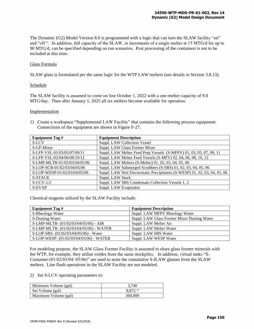
24590-WTP-MDD-PR-01-002, Rev 14 Dynamic (G2) Model Design Document
Page 150
24590-PADC-F00041 Rev 8 (Revised 3/5/2018)
The Dynamic (G2) Model Version 8.0 is programmed with a logic that can turn the SLAW facility “on”
and “off “. In addition, full capacity of the SLAW, in increments of a single melter at 15 MTG/d for up to
90 MTG/d, can be specified depending on run scenarios. Post processing of the containers is not to be
included at this time.
Glass Formula
SLAW glass is formulated per the same logic for the WTP LAW melters (see details in Section 3.8.13).
Schedule
The SLAW facility is assumed to come on line October 1, 2022 with a one-melter capacity of 9.0
MTG/day. Then after January 1, 2025 all six melters become available for operation.
Implementation
1) Create a workspace “Supplemental LAW Facility” that contains the following process equipment.
Connections of the equipment are shown in Figure F-27.
Equipment Tag # Equipment Description
S-LCV Suppl. LAW Collection Vessel
S-GF-Mixer Suppl. LAW Glass Former Mixer
S-LFP-VSL-01/03/05/07/09/11 Suppl. LAW Melter Feed Prep Vessels (S-MFPV) 01, 03, 05, 07, 09, 11
S-LFP-VSL-02/04/06/08/10/12 Suppl. LAW Melter Feed Vessels (S-MFV) 02, 04, 06, 08, 10, 12
S-LMP-MLTR-01/02/03/04/05/06 Suppl. LAW Melters (S-Melter) 01, 02, 03, 04, 05, 06
S-LOP-SCB-01/02/03/04/05/06 Suppl. LAW Submerged Scrubbers (S-SBS) 01, 02, 03, 04, 05, 06
S-LOP-WESP-01/02/03/04/05/06 Suppl. LAW Wet Electrostatic Precipitators (S-WESP) 01, 02, 03, 04, 05, 06
S-STACK Suppl. LAW Stack
S-CCV-1/2 Suppl. LAW SBS Condensate Collection Vessels 1, 2
S-EVAP Suppl. LAW Evaporator
Chemical reagents utilized by the SLAW Facility include:
Equipment Tag # Equipment Description
S-Rheology-Water Suppl. LAW MFPV Rheology Water
S-Dusting-Water Suppl. LAW Glass Former Mixer Dusting Water
S-LMP-MLTR- (01/02/03/04/05/06) - AIR Suppl. LAW Melter Air
S-LMP-MLTR- (01/02/03/04/05/06) - WATER Suppl. LAW Melter Water
S-LOP-SBS- (01/02/03/04/05/06) - Water Suppl. LAW SBS Water
S-LOP-WESP- (01/02/03/04/05/06) - WATER Suppl. LAW WESP Water
For modeling purpose, the SLAW Glass Former Facility is assumed to share glass former minerals with
the WTP, for example, they utilize oxides from the same stockpiles. In addition, virtual tanks “S-
Container-(01/02/03/04/ 05/06)” are used to store the cumulative S-ILAW glasses from the SLAW
melters. Line flush operations in the SLAW Facility are not modeled.
2) Set S-LCV operating parameters to:
Minimum Volume (gal) 3,740
Set Volume (gal) 8,872 a)
Maximum Volume (gal) 360,000
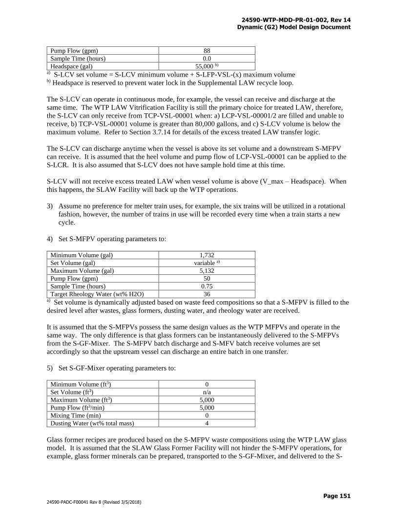
24590-WTP-MDD-PR-01-002, Rev 14 Dynamic (G2) Model Design Document
Page 151
24590-PADC-F00041 Rev 8 (Revised 3/5/2018)
Pump Flow (gpm) 88
Sample Time (hours) 0.0
Headspace (gal) 55,000 b) a) S-LCV set volume = S-LCV minimum volume + S-LFP-VSL-(x) maximum volume b) Headspace is reserved to prevent water lock in the Supplemental LAW recycle loop.
The S-LCV can operate in continuous mode, for example, the vessel can receive and discharge at the
same time. The WTP LAW Vitrification Facility is still the primary choice for treated LAW, therefore,
the S-LCV can only receive from TCP-VSL-00001 when: a) LCP-VSL-00001/2 are filled and unable to
receive, b) TCP-VSL-00001 volume is greater than 80,000 gallons, and c) S-LCV volume is below the
maximum volume. Refer to Section 3.7.14 for details of the excess treated LAW transfer logic.
The S-LCV can discharge anytime when the vessel is above its set volume and a downstream S-MFPV
can receive. It is assumed that the heel volume and pump flow of LCP-VSL-00001 can be applied to the
S-LCR. It is also assumed that S-LCV does not have sample hold time at this time.
S-LCV will not receive excess treated LAW when vessel volume is above (V_max – Headspace). When
this happens, the SLAW Facility will back up the WTP operations.
3) Assume no preference for melter train uses, for example, the six trains will be utilized in a rotational
fashion, however, the number of trains in use will be recorded every time when a train starts a new
cycle.
4) Set S-MFPV operating parameters to:
Minimum Volume (gal) 1,732
Set Volume (gal) variable a)
Maximum Volume (gal) 5,132
Pump Flow (gpm) 50
Sample Time (hours) 0.75
Target Rheology Water (wt% H2O) 36 a) Set volume is dynamically adjusted based on waste feed compositions so that a S-MFPV is filled to the
desired level after wastes, glass formers, dusting water, and rheology water are received.
It is assumed that the S-MFPVs possess the same design values as the WTP MFPVs and operate in the
same way. The only difference is that glass formers can be instantaneously delivered to the S-MFPVs
from the S-GF-Mixer. The S-MFPV batch discharge and S-MFV batch receive volumes are set
accordingly so that the upstream vessel can discharge an entire batch in one transfer.
5) Set S-GF-Mixer operating parameters to:
Minimum Volume (ft3) 0
Set Volume (ft3) n/a
Maximum Volume (ft3) 5,000
Pump Flow (ft3/min) 5,000
Mixing Time (min) 0
Dusting Water (wt% total mass) 4
Glass former recipes are produced based on the S-MFPV waste compositions using the WTP LAW glass
model. It is assumed that the SLAW Glass Former Facility will not hinder the S-MFPV operations, for
example, glass former minerals can be prepared, transported to the S-GF-Mixer, and delivered to the S-
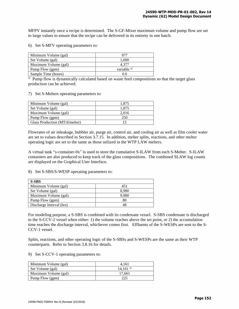
24590-WTP-MDD-PR-01-002, Rev 14 Dynamic (G2) Model Design Document
Page 152
24590-PADC-F00041 Rev 8 (Revised 3/5/2018)
MFPV instantly once a recipe is determined. The S-GF-Mixer maximum volume and pump flow are set
to large values to ensure that the recipe can be delivered in its entirety in one batch.
6) Set S-MFV operating parameters to:
Minimum Volume (gal) 977
Set Volume (gal) 1,000
Maximum Volume (gal) 4,377
Pump Flow (gpm) variable a)
Sample Time (hours) 0.0 a) Pump flow is dynamically calculated based on waste feed compositions so that the target glass
production can be achieved.
7) Set S-Melters operating parameters to:
Minimum Volume (gal) 1,875
Set Volume (gal) 1,875
Maximum Volume (gal) 2,016
Pump Flow (gpm) 250
Glass Production (MT/d/melter) 15
Flowrates of air inleakage, bubbler air, purge air, control air, and cooling air as well as film cooler water
are set to values described in Section 3.7.15. In addition, melter splits, reactions, and other melter
operating logic are set to the same as those utilized in the WTP LAW melters.
A virtual tank “s-container-0x” is used to store the cumulative S-ILAW from each S-Melter. S-ILAW
containers are also produced to keep track of the glass compositions. The combined SLAW log counts
are displayed on the Graphical User Interface.
8) Set S-SBS/S-WESP operating parameters to:
S-SBS
Minimum Volume (gal) 451
Set Volume (gal) 8,980
Maximum Volume (gal) 9,980
Pump Flow (gpm) 80
Discharge Interval (hrs) 48
For modeling purpose, a S-SBS is combined with its condensate vessel. S-SBS condensate is discharged
to the S-CCV-2 vessel when either: 1) the volume reaches above the set point, or 2) the accumulation
time reaches the discharge interval, whichever comes first. Effluents of the S-WESPs are sent to the S-
CCV-1 vessel.
Splits, reactions, and other operating logic of the S-SBSs and S-WESPs are the same as their WTP
counterparts. Refer to Section 3.8.16 for details.
9) Set S-CCV-1 operating parameters to:
Minimum Volume (gal) 4,161
Set Volume (gal) 14,161 a)
Maximum Volume (gal) 17,661
Pump Flow (gpm) 225
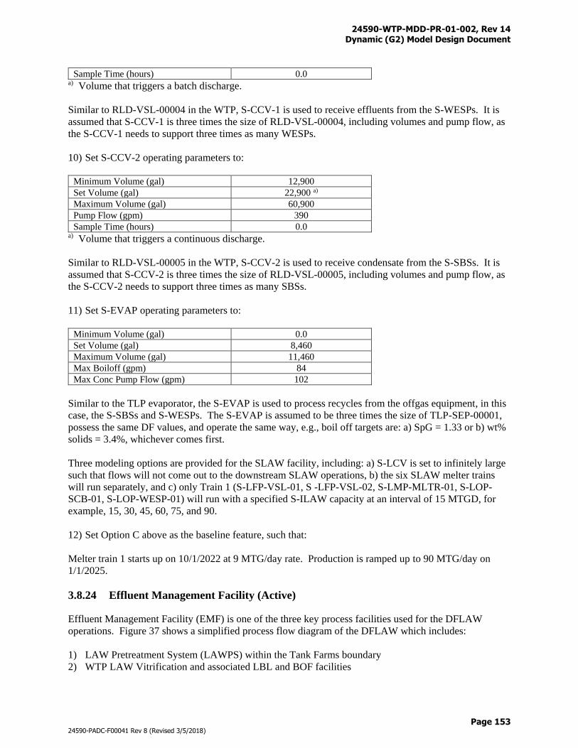
24590-WTP-MDD-PR-01-002, Rev 14 Dynamic (G2) Model Design Document
Page 153
24590-PADC-F00041 Rev 8 (Revised 3/5/2018)
Sample Time (hours) 0.0 a) Volume that triggers a batch discharge.
Similar to RLD-VSL-00004 in the WTP, S-CCV-1 is used to receive effluents from the S-WESPs. It is
assumed that S-CCV-1 is three times the size of RLD-VSL-00004, including volumes and pump flow, as
the S-CCV-1 needs to support three times as many WESPs.
10) Set S-CCV-2 operating parameters to:
Minimum Volume (gal) 12,900
Set Volume (gal) 22,900 a)
Maximum Volume (gal) 60,900
Pump Flow (gpm) 390
Sample Time (hours) 0.0 a) Volume that triggers a continuous discharge.
Similar to RLD-VSL-00005 in the WTP, S-CCV-2 is used to receive condensate from the S-SBSs. It is
assumed that S-CCV-2 is three times the size of RLD-VSL-00005, including volumes and pump flow, as
the S-CCV-2 needs to support three times as many SBSs.
11) Set S-EVAP operating parameters to:
Minimum Volume (gal) 0.0
Set Volume (gal) 8,460
Maximum Volume (gal) 11,460
Max Boiloff (gpm) 84
Max Conc Pump Flow (gpm) 102
Similar to the TLP evaporator, the S-EVAP is used to process recycles from the offgas equipment, in this
case, the S-SBSs and S-WESPs. The S-EVAP is assumed to be three times the size of TLP-SEP-00001,
possess the same DF values, and operate the same way, e.g., boil off targets are: a) SpG = 1.33 or b) wt%
solids = 3.4%, whichever comes first.
Three modeling options are provided for the SLAW facility, including: a) S-LCV is set to infinitely large
such that flows will not come out to the downstream SLAW operations, b) the six SLAW melter trains
will run separately, and c) only Train 1 (S-LFP-VSL-01, S -LFP-VSL-02, S-LMP-MLTR-01, S-LOP-
SCB-01, S-LOP-WESP-01) will run with a specified S-ILAW capacity at an interval of 15 MTGD, for
example, 15, 30, 45, 60, 75, and 90.
12) Set Option C above as the baseline feature, such that:
Melter train 1 starts up on 10/1/2022 at 9 MTG/day rate. Production is ramped up to 90 MTG/day on
1/1/2025.
3.8.24 Effluent Management Facility (Active)
Effluent Management Facility (EMF) is one of the three key process facilities used for the DFLAW
operations. Figure 37 shows a simplified process flow diagram of the DFLAW which includes:
1) LAW Pretreatment System (LAWPS) within the Tank Farms boundary
2) WTP LAW Vitrification and associated LBL and BOF facilities
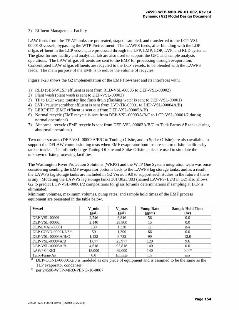
24590-WTP-MDD-PR-01-002, Rev 14 Dynamic (G2) Model Design Document
Page 154
24590-PADC-F00041 Rev 8 (Revised 3/5/2018)
3) Effluent Management Facility
LAW feeds from the TF AP tanks are pretreated, staged, sampled, and transferred to the LCP-VSL-
00001/2 vessels, bypassing the WTP Pretreatment. The LAWPS feeds, after blending with the LOP
offgas effluent in the LCP vessels, are processed through the LFP, LMP, LOP, LVP, and RLD systems.
The glass former facility and analytical lab are also used to support the GFC and sample analysis
operations. The LAW offgas effluents are sent to the EMF for processing through evaporation.
Concentrated LAW offgas effluents are recycled to the LCP vessels, to be blended with the LAWPS
feeds. The main purpose of the EMF is to reduce the volume of recycles.
Figure F-28 shows the G2 implementation of the EMF flowsheet and its interfaces with:
1) RLD (SBS/WESP effluent is sent from RLD-VSL-00005 to DEP-VSL-00002)
2) Plant wash (plant wash is sent to DEP-VSL-00002)
3) TF to LCP waste transfer line flush drain (flushing water is sent to DEP-VSL-00001)
4) LVP (caustic scrubber effluent is sent from LVP-TK-00001 to DEP-VSL-00004A/B)
5) LERF/ETF (EMF effluent is sent out from DEP-VSL-00005A/B)
6) Normal recycle (EMF recycle is sent from DEP-VSL-00003A/B/C to LCP-VSL-00001/2 during
normal operations)
7) Abnormal recycle (EMF recycle is sent from DEP-VSL-00003A/B/C to Tank Farms AP tanks during
abnormal operations)
Two other streams (DEP-VSL-00003A/B/C to Tuning-Offsite, and to Spike-Offsite) are also available to
support the DFLAW commissioning tests when EMF evaporator bottoms are sent to offsite facilities by
tanker trucks. The infinitely large Tuning-Offsite and Spike-Offsite tanks are used to simulate the
unknown offsite processing facilities.
The Washington River Protection Solutions (WRPS) and the WTP One System integration team was once
considering sending the EMF evaporator bottoms back to the LAWPS lag storage tanks, and as a result,
the LAWPS lag storage tanks are included in G2 Version 9.0 to support such studies in the future if there
is any. Modeling the LAWPS lag storage tanks 301/3023/303 (named LAWPS-1/2/3 in G2) also allows
G2 to predict LCP-VSL-00001/2 compositions for glass formula determinations if sampling at LCP is
eliminated.
Minimum volumes, maximum volumes, pump rates, and sample hold times of the EMF process
equipment are presented in the table below.
Vessel V_min
(gal)
V_max
(gal)
Pump Rate
(gpm)
Sample Hold Time
(hr)
DEP-VSL-00001 2,546 8,846 56 0.0
DEP-VSL-00002 2,140 28,800 15 0.0
DEP-EVAP-00001 130 1,330 11 n/a
DEP-COND-00001/2/3 a) 50 1,300 66 0.0
DEP-VSL-00003A/B/C 1,132 8,732 90 12.0
DEP-VSL-00004A/B 1,677 23,977 120 9.6
DEP-VSL-00005A/B 4,618 93,818 140 0.0
LAWPS-1/2/3 18,000 89,000 140 0.0 b)
Tank-Farm-AP 0.0 Infinite n/a n/a a) DEP-COND-00001/2/3 is modeled as one piece of equipment and is assumed to be the same as the
TLP evaporator condenser. b) per 24590-WTP-MRQ-PENG-16-0007.
24590-WTP-MDD-PR-01-002, Rev 14 Dynamic (G2) Model Design Document
Page 155
24590-PADC-F00041 Rev 8 (Revised 3/5/2018)
Vessel Tag # Equipment Description
DEP-VSL-00001 Low Point Drain Vessel
DEP-VSL-00001 receives 1,600 gallons of flush water after each LAWPS to LCP vessel transfer. The
vessel works in a batch mode such that it will be filled to its upper set volume then discharged to DEP-
VSL-00002.
Vessel Tag # Equipment Description
DEP-VSL-00002 Evaporator Feed Vessel
DEP-VSL-00002 works in a continuous mode such that it can receive and discharge at the same time.
The vessel receives acidic SBS/WESP effluents from RLD-VSL-00005, flush water from DEP-VSL-
00001, a 600-gallon plant wash water each day, and caustic for pH adjustment. Reactions take place in
DEP-VSL-00002 where ammonium is converted to ammonia, boric acid is converted to
tetrahydroxyborate, and pH is lifted to ≥ 11. The charge-balance, percent-affecting pH algorithm (Section
3.7.22) is applied for pH calculations.
Convert ammonium to ammonia:
NH4+ (l) + OH- (l) → NH3 (l) + H2O (l) CF = 0.999
Convert boric acid to tetrhydroxyborate:
B+3 (l) + 3 OH(Bound) (l) + OH- (l) → B+3 (l) + 4 OH(Bound) (l) CF = 1.0
The DEP-VSL-00002 pump rate is adjusted batchwise such that the boil-off rate and bottoms SpG
operating conditions of the evaporator can be met (see DEP-EVAP-00001 discussion below for details).
Vessel Tag # Equipment Description
DEP-EVAP-00001 Evaporator Separator Vessel
The EMF evaporator is modeled to receive feeds from DEP-VSL-00002 at a pump rate up to 15 gpm.
Evaporator bottom SpG target is set to one of the three below, whichever reaches first:
{
SpG = 1.2
SpG = when Cl- reaches 2 wt%
SpG = when 137Cs concentration reaches 1.9 x 10⁻⁴ Ci/liter
}
Actual feed rate to the evaporator is limited by the maximum boil-off rate of 11 gpm. Evaporator
concentrate pump capacity is 45 gpm. The offgas from DEP-EVAP-00001 is routed through DEP-
COND-00001/2/3. Splits for the evaporator are shown in Table D-28 (values adopted from the TLP-SEP-
00001 evaporator). 95% of the ammonia entering the evaporator gasifies and splits to DEP-COND-
00001/2/3, however, G2 tracks the gaseous NH3 in the liquid phase (for material balance purpose only).
Naphthalene split is calculated per the equation below (derivation is given in Attachment A1 of 24590-WTP-MCR-
PENG-17-0015):
y = 0.011675x-1.002317
24590-WTP-MDD-PR-01-002, Rev 14 Dynamic (G2) Model Design Document
Page 156
24590-PADC-F00041 Rev 8 (Revised 3/5/2018)
where:
y = efficiency factor, or fraction retained (unitless)
x = evaporator overheads to bottoms ratio (unitless)
This correlation is based on:
Henry’s LAW constant 𝑘𝐻0 = 2.1 mol/l·atm at 298 ºK
Evaporator pressure P = 0.078 atm
Evaporator temperature T = 323 °K
Vessel Tag # Equipment Description
DEP-COND-00001/2/3 Evaporator Condensers
The EMF evaporator condensers receive boil-offs and associated split components from DEP-
EVAP-00001. Offgas is condensed based on splits shown in Table D-29 (values adopted from TLP-
DMST-00001). The overhead split goes to the EMF stack and the condensate split goes to DEP-VSL-
00004A/B. 8.06% of the liquid ammonia in DEP-COND-00001/2/3 is converted to gaseous NH3 that
goes out with the overhead. Remaining liquid NH3 goes out with the condensate.
Naphthalene split is assumed to behave like the SBS, therefore 33% of the C10H8 entering the evaporator
condensers is removed and sent to the effluent stream.
Vessel Tag # Equipment Description
DEP-VSL-00003A Evaporator Concentrate Vessel
DEP-VSL-00003B Evaporator Concentrate Vessel
DEP-VSL-00003C Evaporator Concentrate Vessel
DEP-VSL-00003A/B/C receive concentrates from the EMF evaporator. The vessels operate in a
rotational order such that each vessel will go through the “fill”, “sample”, and “transfer” processes. The
filling of a concentrate vessel is monitored and coordinated with the LAWPS-1/2/3 to LCP-VSL-00001/2
transfer volumes so that the feed to recycle ratio as described in Section 3.8.13 can be determined. The
feed to recycle ratio of the current cycle is used to guide the feed/recycle blending operations of the next
cycle. An evaporator concentrate vessel is sampled once it is filled to the upper set volume. Sample hold
time is set to 12 hours.
Evaporator concentrate can be fully recycled (100%) or partially recycled (x%) and partially returned
(100 – x%), respectively, depending on operation scenarios. Recycle is defined as that EMF concentrate
is sent to the LCP vessels while return is defined as that concentrate is sent to the Tank Farm. Under
normal operating conditions, 100% of the evaporator concentrate is recycled. The Dynamic (G2) Model
Version 9.0 is defaulted to the normal operating scenarios.
Vessel Tag # Equipment Description
DEP-VSL-00004A Overhead Sampling Vessel
DEP-VSL-00004B Overhead Sampling Vessel
The Overhead Sampling Vessels receive evaporator condensate from DEP-COND-00001/2/3 and caustic
scrubber effluent from LVP-TK-00001. Water, used to model condensate from the vacuum eductors, is
also delivered from a chem-add to the DEP-VSL-00004A/B vessels at a rate of 0.96 gpm whenever DEP-
EVAP-00001 is operating. The DEP-VSL-00004A and DEP-VSL-00004B vessels rotate daily in
operations such that one vessel will receive for 24 hours while the other will be sampled then discharged.
24590-WTP-MDD-PR-01-002, Rev 14 Dynamic (G2) Model Design Document
Page 157
24590-PADC-F00041 Rev 8 (Revised 3/5/2018)
Sample hold time is set to 9.6 hours. The emptied DEP-VSL-00004 vessel can be switched to
filling mode when the filled DEP-VSL-00004 vessel starts sampling. This sampling scheme ensures that
one DEP-VSL-00004 is always open to receive. DEP-VSL-00004A/B contents are transferred to a
currently available DEP-VSL-00005A/B vessel.
Vessel Tag # Equipment Description
DEP-VSL-00005A Process Condensate Lag Storage Vessel
DEP-VSL-00005B Process Condensate Lag Storage Vessel
The Process Condensate Lag Storage Vessels receive, stage, and transfer effluents from DEP-VSL-
00004A/B. The two DEP-VSL-00005 vessels work alternately in batch mode. Once a receiving vessel
reaches its upper set volume, the content is discharged to the LERF/ETF facilities. Sampling is not
required for the vessels.
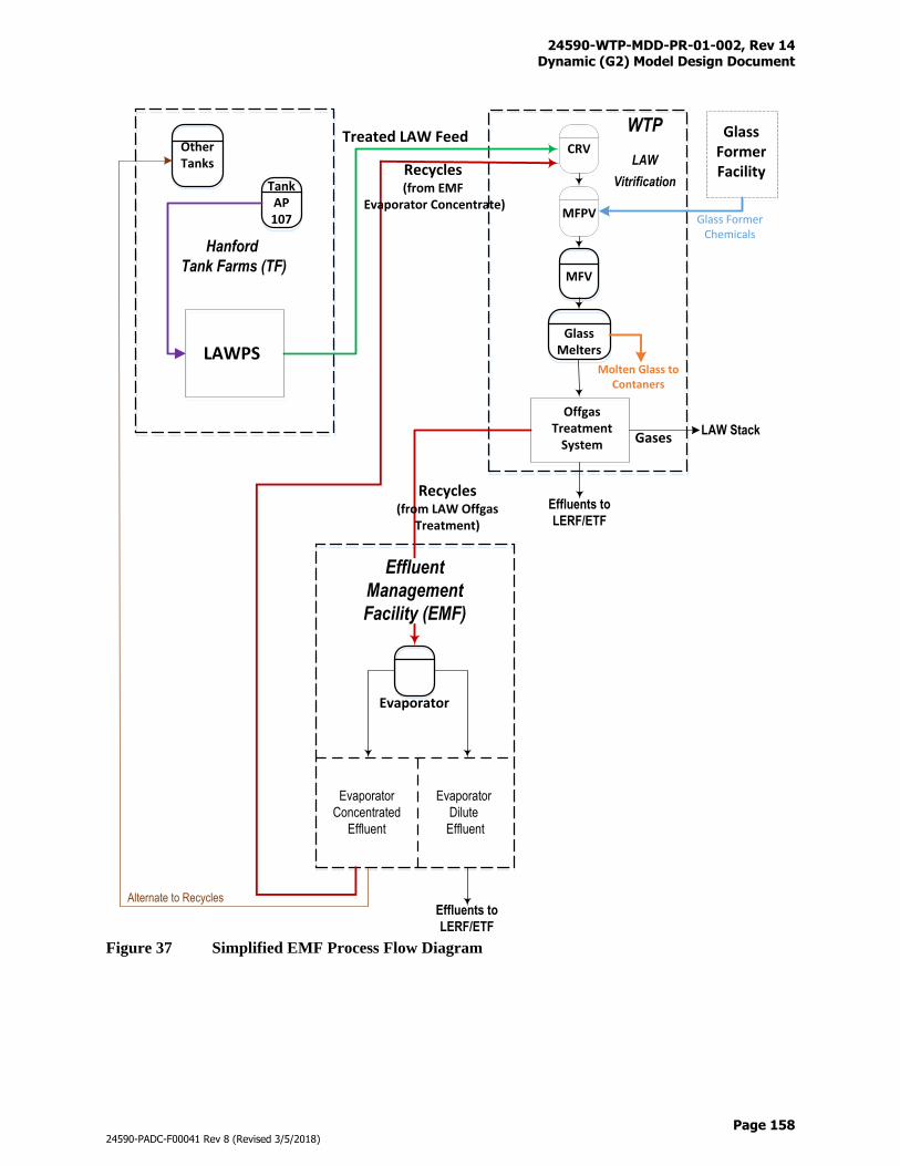
24590-WTP-MDD-PR-01-002, Rev 14 Dynamic (G2) Model Design Document
Page 158
24590-PADC-F00041 Rev 8 (Revised 3/5/2018)
Figure 37 Simplified EMF Process Flow Diagram
CRV
MFPV
MFV
Molten Glass to Contaners
GlassMelters
Other Tanks
Hanford
Tank Farms (TF)
Gases
Effluent
Management
Facility (EMF)
Evaporator
Concentrated
Effluent
Evaporator
Dilute
Effluent
Effluents to
LERF/ETF
LAWPS
TankAP107
Treated LAW Feed
Recycles (from EMF
Evaporator Concentrate)
Offgas Treatment
System
Evaporator
LAW Stack
Effluents to
LERF/ETF
Recycles (from LAW Offgas
Treatment)
WTP
LAW
Vitrification
Alternate to Recycles
Glass Former Facility
Glass Former Chemicals
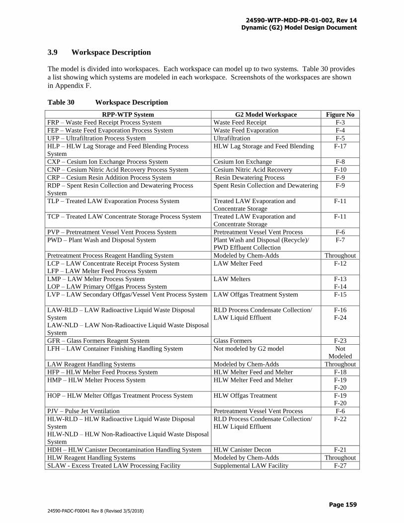
24590-WTP-MDD-PR-01-002, Rev 14 Dynamic (G2) Model Design Document
Page 159
24590-PADC-F00041 Rev 8 (Revised 3/5/2018)
3.9 Workspace Description
The model is divided into workspaces. Each workspace can model up to two systems. Table 30 provides
a list showing which systems are modeled in each workspace. Screenshots of the workspaces are shown
in Appendix F.
Table 30 Workspace Description
RPP-WTP System G2 Model Workspace Figure No
FRP – Waste Feed Receipt Process System Waste Feed Receipt F-3
FEP – Waste Feed Evaporation Process System Waste Feed Evaporation F-4
UFP – Ultrafiltration Process System Ultrafiltration F-5
HLP – HLW Lag Storage and Feed Blending Process
System
HLW Lag Storage and Feed Blending F-17
CXP – Cesium Ion Exchange Process System Cesium Ion Exchange F-8
CNP – Cesium Nitric Acid Recovery Process System Cesium Nitric Acid Recovery F-10
CRP – Cesium Resin Addition Process System Resin Dewatering Process F-9
RDP – Spent Resin Collection and Dewatering Process
System
Spent Resin Collection and Dewatering F-9
TLP – Treated LAW Evaporation Process System Treated LAW Evaporation and
Concentrate Storage
F-11
TCP – Treated LAW Concentrate Storage Process System Treated LAW Evaporation and
Concentrate Storage
F-11
PVP – Pretreatment Vessel Vent Process System Pretreatment Vessel Vent Process F-6
PWD – Plant Wash and Disposal System Plant Wash and Disposal (Recycle)/
PWD Effluent Collection
F-7
Pretreatment Process Reagent Handling System Modeled by Chem-Adds Throughout
LCP – LAW Concentrate Receipt Process System
LFP – LAW Melter Feed Process System
LAW Melter Feed F-12
LMP – LAW Melter Process System
LOP – LAW Primary Offgas Process System
LAW Melters
F-13
F-14
LVP – LAW Secondary Offgas/Vessel Vent Process System LAW Offgas Treatment System F-15
LAW-RLD – LAW Radioactive Liquid Waste Disposal
System
LAW-NLD – LAW Non-Radioactive Liquid Waste Disposal
System
RLD Process Condensate Collection/
LAW Liquid Effluent
F-16
F-24
GFR – Glass Formers Reagent System Glass Formers F-23
LFH – LAW Container Finishing Handling System Not modeled by G2 model Not
Modeled
LAW Reagent Handling Systems Modeled by Chem-Adds Throughout
HFP – HLW Melter Feed Process System HLW Melter Feed and Melter F-18
HMP – HLW Melter Process System HLW Melter Feed and Melter F-19
F-20
HOP – HLW Melter Offgas Treatment Process System HLW Offgas Treatment F-19
F-20
PJV – Pulse Jet Ventilation Pretreatment Vessel Vent Process F-6
HLW-RLD – HLW Radioactive Liquid Waste Disposal
System
HLW-NLD – HLW Non-Radioactive Liquid Waste Disposal
System
RLD Process Condensate Collection/
HLW Liquid Effluent
F-22
HDH – HLW Canister Decontamination Handling System HLW Canister Decon F-21
HLW Reagent Handling Systems Modeled by Chem-Adds Throughout
SLAW - Excess Treated LAW Processing Facility Supplemental LAW Facility F-27
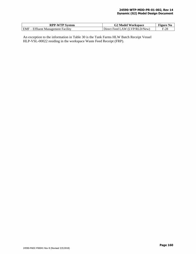
24590-WTP-MDD-PR-01-002, Rev 14 Dynamic (G2) Model Design Document
Page 160
24590-PADC-F00041 Rev 8 (Revised 3/5/2018)
RPP-WTP System G2 Model Workspace Figure No
EMF – Effluent Management Facility Direct Feed LAW (LVP/RLD/New) F-28
An exception to the information in Table 30 is the Tank Farms HLW Batch Receipt Vessel
HLP-VSL-00022 residing in the workspace Waste Feed Receipt (FRP).
24590-WTP-MDD-PR-01-002, Rev 14 Dynamic (G2) Model Design Document
Page 161
24590-PADC-F00041 Rev 8 (Revised 3/5/2018)
4 Model Construction
The Dynamic (G2) Model consists of a G2 core and a set of peripheral tools as shown in Figure 1. The
G2 core is developed using the Gensym G2 software development platform as required by the WTP
contract. Due to the scale and size of data to and from the G2 core, peripheral tools are needed to support
the dynamic flowsheet operations, including data inputs and outputs, access to external solver for
numerical solutions, and post- model run data manipulation.
Peripheral tools for data inputs and outputs include:
Microsoft Access 2016 database for feed vector import
Microsoft Access 2016 database for line flush table import
Oracle 11g database for data outputs, including SQL*Plus
Communications between the G2 core and the databases are enabled through the use of G2-ODBC bridge.
As an option, the G2 core can also call an external Excel macro to solve a set of highly non-linear
equations for determination of advance glass formulas. This option is not currently in the G2 Version 9.0
baseline but has been used in 24590-WTP-RPT-PE-13-003, 2013 Tank Utilization Assessment (TUA)
Part 1: Potential Impact of Advanced Glass Models on the WTP. Communications between the G2 core
and the Excel macro is enabled using:
G2 ActiveXLink and Gateway products
Visual Basic for Application (VBA) bridge with Excel
In addition, the Dynamic (G2) Flowsheet utilizes the following tools for post- model run data
manipulation and automation:
Oracle scripts for Oracle 11g database table updates
MATLAB scripts for data plotting
Visual C# routines (G2 Mass Balance Calculator [G2MBC]) for mass balance diagram generation
Installation and configuration control of the modeling platform are discussed in the System Design for
Process Modeling (24590-WTP-PL-TE-01-008). The following discusses the design and construction of
the G2 core and its peripherals.
4.1 G2 Core
The G2 core is constructed of the Gensym G2 components and the Dynamic (G2) Flowsheet components
as shown in Figure 38. Relationship between the two is revealed from the left to the right as the Gensym
G2 components are used to build the Dynamic (G2) Flowsheet. In other words, the Gensym G2
components are the tools for the development of the G2 model. For reader who are more familiar with
other programming languages, many of the Gensym G2 components in Figure 38 can also be referred to
as system files, or library files in software industry terms.
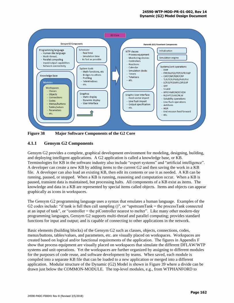
24590-WTP-MDD-PR-01-002, Rev 14 Dynamic (G2) Model Design Document
Page 162
24590-PADC-F00041 Rev 8 (Revised 3/5/2018)
Figure 38 Major Software Components of the G2 Core
4.1.1 Gensym G2 Components
Gensym G2 provides a complete, graphical development environment for modeling, designing, building,
and deploying intelligent applications. A G2 application is called a knowledge base, or KB.
Terminologies for KB in the software industry also include “expert systems” and “artificial intelligence”.
A developer can create a new KB by adding items to the current G2 and then saving the work in a KB
file. A developer can also load an existing KB, then edit its contents or use it as needed. A KB can be
running, paused, or stopped. When a KB is running, reasoning and computation occur. When a KB is
paused, transient data is maintained, but processing halts. All components of a KB exist as items. The
knowledge and data in a KB are represented by special items called objects. Items and objects can appear
graphically as icons in workspaces.
The Gensym G2 programming language uses a syntax that emulates a human language. Examples of the
G2 codes include: “if tank is full then call sampling ()”, or “upstreamTank = the processTank connected
at an input of tank”, or “controller = the piController nearest to melter”. Like many other modern-day
programming languages, Gensym G2 supports multi-thread and parallel computing; provides standard
functions for input and output; and is capable of connecting to other applications in the network.
Basic elements (building blocks) of the Gensym G2 such as classes, objects, connections, codes,
menus/buttons, tables/values, and parameters, etc. are visually placed on workspaces. Workspaces are
created based on logical and/or functional requirements of the application. The figures in Appendix F
show that process equipment are visually placed on workspaces that simulate the different DFLAW/WTP
systems and unit operations. Yet the workspaces are further organized by assigning to different modules
for the purposes of code reuse, and software development by teams. When saved, each module is
compiled into a separate KB file that can be loaded to a new application or merged into a different
application. Modular structure of the Dynamic (G2) Model is shown in Figure 39 where a divide can be
drawn just below the COMMON-MODULE. The top-level modules, e.g., from WTPHANFORD to
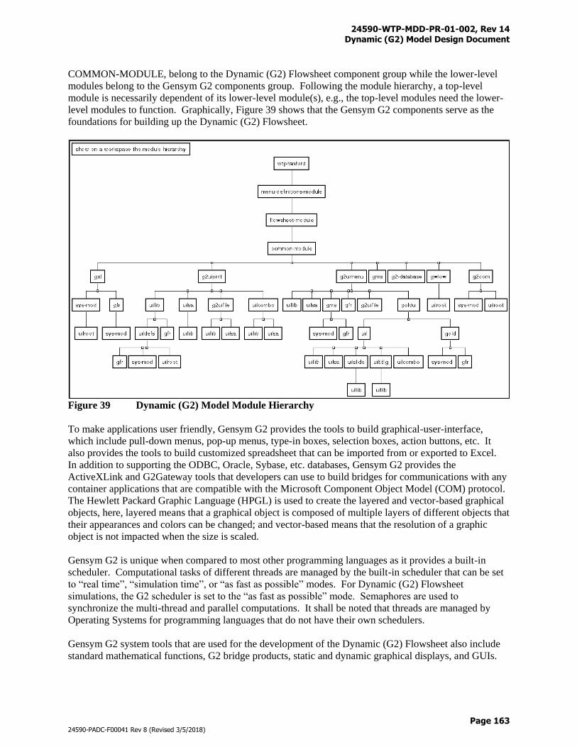
24590-WTP-MDD-PR-01-002, Rev 14 Dynamic (G2) Model Design Document
Page 163
24590-PADC-F00041 Rev 8 (Revised 3/5/2018)
COMMON-MODULE, belong to the Dynamic (G2) Flowsheet component group while the lower-level
modules belong to the Gensym G2 components group. Following the module hierarchy, a top-level
module is necessarily dependent of its lower-level module(s), e.g., the top-level modules need the lower-
level modules to function. Graphically, Figure 39 shows that the Gensym G2 components serve as the
foundations for building up the Dynamic (G2) Flowsheet.
Figure 39 Dynamic (G2) Model Module Hierarchy
To make applications user friendly, Gensym G2 provides the tools to build graphical-user-interface,
which include pull-down menus, pop-up menus, type-in boxes, selection boxes, action buttons, etc. It
also provides the tools to build customized spreadsheet that can be imported from or exported to Excel.
In addition to supporting the ODBC, Oracle, Sybase, etc. databases, Gensym G2 provides the
ActiveXLink and G2Gateway tools that developers can use to build bridges for communications with any
container applications that are compatible with the Microsoft Component Object Model (COM) protocol.
The Hewlett Packard Graphic Language (HPGL) is used to create the layered and vector-based graphical
objects, here, layered means that a graphical object is composed of multiple layers of different objects that
their appearances and colors can be changed; and vector-based means that the resolution of a graphic
object is not impacted when the size is scaled.
Gensym G2 is unique when compared to most other programming languages as it provides a built-in
scheduler. Computational tasks of different threads are managed by the built-in scheduler that can be set
to “real time”, “simulation time”, or “as fast as possible” modes. For Dynamic (G2) Flowsheet
simulations, the G2 scheduler is set to the “as fast as possible” mode. Semaphores are used to
synchronize the multi-thread and parallel computations. It shall be noted that threads are managed by
Operating Systems for programming languages that do not have their own schedulers.
Gensym G2 system tools that are used for the development of the Dynamic (G2) Flowsheet also include
standard mathematical functions, G2 bridge products, static and dynamic graphical displays, and GUIs.
24590-WTP-MDD-PR-01-002, Rev 14 Dynamic (G2) Model Design Document
Page 164
24590-PADC-F00041 Rev 8 (Revised 3/5/2018)
For the full capability of the Gensym G2 development platform, refer to G2 Reference Manual (Gensym
Corporation, 2004)
4.1.2 Dynamic (G2) Flowsheet Components
As mentioned in Section 4.1.1, the Dynamic (G2) Flowsheet components are built upon the Gensym G2
components. The first step in building the Dynamic (G2) Flowsheet is to design classes for process
equipment and process control that can be used to create graphical objects for the flowsheet. Figure 2
presents a complete list of classes for the process equipment that are modeled. The classes are presented
in a hierarchy way where the child, grand child, great-grand child inheritance paths can be traced. The
classes that represent the actual DFLAW/WTP process equipment are designed to be instantiable. Table
2 presents the object names of process equipment that are modeled, the classes that are used to create the
equipment objects, and the component lists that are used for mass balance calculations. Other classes,
including the monitoring device, controller, reaction, calendar, simulation clock, timer, and totalizer, etc.
classes are also designed to meet the modeling needs. With a summary view, the figures in Appendix F
present:
the graphical objects of the instantiable classes (show existence of equipment objects)
the layout of the process equipment and monitoring/controlling devices (show where they belong)
connections (show how equipment are put together into unit operations and systems)
Refer to the Dynamic (G2) Flowsheet Version 9.0 model files (Table Q-1 of Appendix Q) for further
details.
With the process equipment, control, and other supporting classes being designed, the DFLAW/WTP
flowsheet can be built in accordance with the requirements described in Section 3. Facilities and
associated systems where processes are explicitly (visible) modeled include:
PT - FRP/HLP22/FEP/UFP/HLP/CXP/CNP/RDP/CRP/TLP/TCP/PWD/PVP/PJV/RLD
LAW - LCP/LFP/LMP/LOP/LVP/RLD
HLW - HFP/HMP/HOP/HDH/RLD
SLAW - Up to six LCP/LFP/LMP/LOP trains, and an offgas effluent evaporation system
GFF - Systems 100 – 700, and glass former mixers
EMF - DEP vessels, evaporator
BOF - Chemical reagents, process water
Notice that chemical reagent and process water sources from the Balance of Facility are placed in the
systems where they are used.
Facility where processes are implicitly (invisible) modeled includes:
Analytical Laboratory (LBL)
Sampling is modeled at vessels where analytical results are required for process decisions. Although the
LBL is not explicitly modeled, hold times are applied to the sampling vessels to simulate the laboratory
sample turnaround times. In addition, analytical results of the samples are obtained from mass balance
calculations which simulate the laboratory analyses.
24590-WTP-MDD-PR-01-002, Rev 14 Dynamic (G2) Model Design Document
Page 165
24590-PADC-F00041 Rev 8 (Revised 3/5/2018)
Modeling of the offsite facilities are based on assumptions, for example, the following facilities are
assumed to have unlimited treatment/disposal capacities such that they will not hinder the DFLAW/WTP
operations:
Offsite treatment/disposal for commissioning effluent
LERF/ETF for operation effluent
Offsite permanent disposal for ILAW
Offsite permanent disposal for IHLW
Tank Farms for feeds from and returns to
Atmospheric releases from stacks
It is assumed that the media (feeds, effluents, glasses, recycles, and gaseous emissions) meet the quality,
health and safety, and permit requirements. Process equipment, unit operations, and systems in the
modeled facilities are discussed in Section 3.8.
The Dynamic (G2) Flowsheet models the following process operations in the DFLAW/WTP:
Pumping
Sampling
Storage
Reactions
Phase Equilibrium
Separations
Splits
These process operations are modeled based on the dynamic mass balance calculations of various process
equipment which may contain: a) liquid; b) solid; c) oxide; and d) gas, as appropriate, depending on
functions of the equipment. Table 2 presents a list of the modeled equipment and the phases of materials
that are associated with the equipment. Numerical methods for the dynamic mass balance calculations are
based on array additions, subtractions, and multiplications. The arrays for dynamic mass balance
calculations include: a) liquid array; b) solid array; c) oxide array; and d) gas array. Each array contains a
pre-defined number of chemical components (see Appendix A for details).
Pumping
Pumping is the most basic process operation that takes place throughout the plant. When pumping takes
place, mass is transferred from an upstream equipment to a downstream equipment. Depending on
equipment types, the pumping/receiving equipment can have masses in combinations of liquid, solid,
oxide, and gas forms (see Table 2 for the component arrays that are modeled in each DFLAW/WTP
equipment). Numerical methods for calculating the mass transfer are described in the equations below.
∆V = min (VD, VR, VC)
Frac = ∆V / VT
Where:
∆V = Volume to be discharged in a time step (gal)
Frac = Fraction of upstream volume to be discharged (unitless)
VD = Upstream dischargable volume (gal)
VR = Downstream receivable volume (gal)
VC = Pump capacity in a time step (gal)
24590-WTP-MDD-PR-01-002, Rev 14 Dynamic (G2) Model Design Document
Page 166
24590-PADC-F00041 Rev 8 (Revised 3/5/2018)
VT = Current total volume of upstream equipment (gal)
Notice that VT is the combined volumes of liquid, solid, and oxide. It is assumed that vessels are ideally
mixed so the volume fraction of an upstream equipment equals to the mass fraction of the same
equipment. Mass balance of the liquid, solid, and oxide components of the upstream equipment can be
calculated with:
L’up = (1 – Frac) * Lup
S’up = (1 – Frac) * Sup
O’up = (1 – Frac) * Oup
The mass transfer fraction of the gas components (gFrac) is determined based on the flowrate, and
operating pressure and temperature of the process equipment.
G’up = (1 – gFrac) * Gup
Where:
Lup = Liquid array of upstream equipment before pumping (kg-mole)
Sup = Solid array of upstream equipment before pumping (kg-mole)
Oup = Oxide array of upstream equipment before pumping (kg-mole)
Gup = Gas array of upstream equipment before pumping (kg-mole)
L’up = Liquid array of upstream equipment after pumping (kg-mole)
S’up = Solid array of upstream equipment after pumping (kg-mole)
O’up = Oxide array of upstream equipment after pumping (kg-mole)
G’up = Gas array of upstream equipment after pumping (kg-mole)
Mass balance of the liquid, solid, and oxide components of the downstream equipment can be calculated
with:
L’down = Ldown + Frac * Lup
S’down = Sdown + Frac * Sup
O’down = Odown + Frac * Oup
G’down = Gdown + gFrac * Gup
Where:
Ldown = Liquid array of downstream equipment before pumping (kg-mole)
Sdown = Solid array of downstream equipment before pumping (kg-mole)
Odown = Oxide array of downstream equipment before pumping (kg-mole)
Gdown = Gas array of downstream equipment before pumping (kg-mole)
L’down = Liquid array of downstream equipment after pumping (kg-mole)
S’down = Solid array of downstream equipment after pumping (kg-mole)
O’down = Oxide array of downstream equipment after pumping (kg-mole)
G’down = Gas array of downstream equipment after pumping (kg-mole)
Sampling
Through the mass balance calculations for pumping, masses into, out of, and remained in an equipment
are known internally to the Dynamic (G2) Model. At the time of a sampling event, chemical
compositions are extracted from the liquid, solid, oxide, and gas arrays of the equipment for data outputs
and used to make process decisions. Process decisions made include: a) leach vs. no leach decision; b)
caustic addition for pH adjustment and solubility maintenance operations; c) glass formulations, etc.
24590-WTP-MDD-PR-01-002, Rev 14 Dynamic (G2) Model Design Document
Page 167
24590-PADC-F00041 Rev 8 (Revised 3/5/2018)
When applicable, hold times are applied such that the equipment cannot be used to receive and discharge
until laboratory results have become available.
Information available from a sampling event include:
MLi = Liquid array of sample equipment
MSi = Solid array of sample equipment
MOj = Oxide array of sample equipment
VL = Liquid volume
VS = Solid volume
Where:
MLi = Mass of liquid component i (i = 0 to 162) (kg-mole)
MSi = Mass of solid component i (i = 0 to 162) (kg-mole)
MOj = Mass of oxide component j (j = 0 to 73) (kg-mole)
VL = Liquid volume of sample equipment (gal)
VS = Solid volume (solid + oxide) of sample equipment (gal)
Storage
Storage is the remaining mass in the mass balance equation for a process equipment:
Msto = Min - Mout
Where:
Msto = Mass in storage (kg-mole)
Min = Mass into the equipment (kg-mole)
Mout = Mass out of the equipment (kg-mole)
Notice that the mass terms include the liquid, solid, oxide, and gas arrays. Storage of a process equipment
is dynamically tracked, such that: a) it is changing when it is being filled or discharged; or b) it is steady
when filling or pumping do not take place.
Reactions
Chemical reactions, such as those discussed in Section 3.8, are modeled based on the mass balance
principles. Reactants and products are tracked with the liquid, solid, oxide, and gas component arrays.
Reactants are converted to products in accordance with simple stoichiometry. Reaction extents are
governed by either: a) pre-defined, or b) dynamically calculated conversion factors. Reactions involve
phase changes such that reactants and products can exist in the liquid, solid, oxide, and gas phases as
appropriate.
Phase Equilibrium
Phase equilibrium is a special case of chemical reactions where reactant and product are the same material
but exist in different phases. The solubility applications of oxalate, phosphate, and aluminum (Section
3.7.16) are examples of phase equilibrium.
Separations
The separation processes modeled include:
24590-WTP-MDD-PR-01-002, Rev 14 Dynamic (G2) Model Design Document
Page 168
24590-PADC-F00041 Rev 8 (Revised 3/5/2018)
Evaporation
Filtration
Ion exchange
Scrubbing
Evaporators are run based on constraints of the design and control parameters. Design parameters include
evaporator feed pump maximum flowrate, evaporator maximum boil-off rate, and evaporator concentrate
pump maximum flowrate. Control parameters are SpG and wt% solids of the evaporator concentrate. For
the EMF evaporator, the SpG is also correlated to the wt% of Cl and radioactivity of Cs-137 (Section
3.8.24). The maximum boil-off rate is used to determine the quantity of water to be sent to the overhead
from the feed entering the evaporator. The feed rate: a) must not exceed the feed pump maximum
flowrate; and b) is adjusted so that after the evaporation, it meets the SpG and wt% solids constraints.
Filtration operations modeled include the UFP ultrafilters (Section 3.8.3) and the cesium ion exchange
guard filters (Section 3.8.4). For the UFP ultrafilters, slurry is pumped to the filter loop where liquid is
forced through the filters in accordance with calculated flux rates (Eq. 28), while the concentrated slurry
is circulated back to the ultrafiltration feed vessels. For the ion exchange guard filters, 100% of the solids
is captured which then is periodically recycled to the PWD vessels by filter back pulsing operations.
The cesium ion exchange columns remove a pre-defined fractions of dissolved cesium, barium, and
potassium from the feed during the loading cycle. For every kg-mole of 134-Cs, 137-Cs, 137m-Ba, Cs+
and K+ captured during ion exchange, 1 kg-mole of Nap+ is released from the resin surface. The
captured cations are released from the resins later during the elusion cycle.
Scrubbing occurs in the offgas systems where liquid and solid particulates and gas components are
partially or completely captured.
Splits
Split is a G2 terminology for decontamination factor. Splits are defined as the fractions of materials
entering a process equipment to be sent to the overhead or to the bottom, based on modeling convenience.
Splitting is applied to various process equipment (Appendix D).
A simulation engine is constructed, and when running, will advance two simulation clocks and maintain
two calendars. The two simulation clocks are designed to have different resolutions to accomplish
modeling needs due to equipment size and flowrate reasons. The simulation clocks are set to zero in the
beginning of a model run, or called at time zero of a run. Time steps are set to 6-minute for clock 1 and
1-minute for clock 2 (Section 3). The Dynamic (G2) Model also maintains two calendars, a Julian
calendar and an International Fixed calendar (or called Gregorian calendar). The Julian date calendar is
invisible and set valid between 2415080 (3/1/1900) and 2488128 (2/28/2100). The valid date range is set
to cover the entire life of the Hanford projects, such as from the beginning of uranium/plutonium
productions in the 1930s to the end of the cleanups before the year 2100. When a model is running, the
Julian date calendar is converted to the International Fixed calendar which is visible and used for process
controls and data outputs.
Variables, operating parameters, arrays, and attributes of the process equipment objects are
initialized when KB files are loaded to G2 or when a run is restarted. Figure 40 shows the Graphical User
Interface that is used to set:
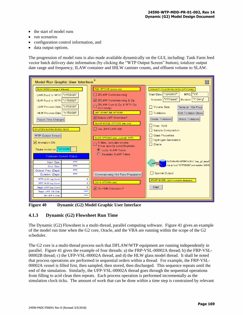
24590-WTP-MDD-PR-01-002, Rev 14 Dynamic (G2) Model Design Document
Page 169
24590-PADC-F00041 Rev 8 (Revised 3/5/2018)
the start of model runs
run scenarios
configuration control information, and
data output options.
The progression of model runs is also made available dynamically on the GUI, including: Tank Farm feed
vector batch delivery date information (by clicking the “WTP Output Screen” button), totalizer output
date range and frequency, ILAW container and IHLW canister counts, and effluent volume to SLAW.
Figure 40 Dynamic (G2) Model Graphic User Interface
4.1.3 Dynamic (G2) Flowsheet Run Time
The Dynamic (G2) Flowsheet is a multi-thread, parallel computing software. Figure 41 gives an example
of the model run time when the G2 core, Oracle, and the VBA are running within the scope of the G2
scheduler.
The G2 core is a multi-thread process such that DFLAW/WTP equipment are running independently in
parallel. Figure 41 gives the example of four threads: a) the FRP-VSL-00002A thread; b) the FRP-VSL-
00002B thread; c) the UFP-VSL-00002A thread, and d) the HLW glass model thread. It shall be noted
that process operations are performed in sequential orders within a thread. For example, the FRP-VSL-
00002A vessel is filled first, then sampled, then stored, then discharged. This sequence repeats until the
end of the simulation. Similarly, the UFP-VSL-00002A thread goes through the sequential operations
from filling to acid clean then repeats. Each process operation is performed incrementally as the
simulation clock ticks. The amount of work that can be done within a time step is constrained by relevant
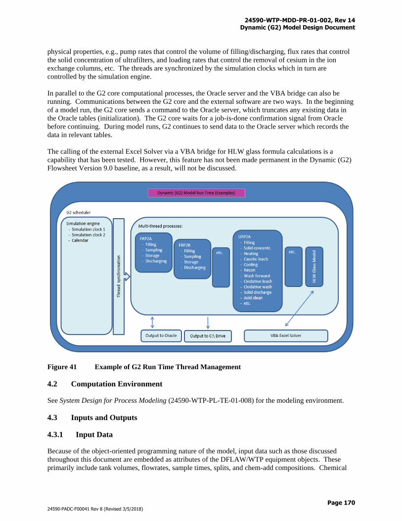
24590-WTP-MDD-PR-01-002, Rev 14 Dynamic (G2) Model Design Document
Page 170
24590-PADC-F00041 Rev 8 (Revised 3/5/2018)
physical properties, e.g., pump rates that control the volume of filling/discharging, flux rates that control
the solid concentration of ultrafilters, and loading rates that control the removal of cesium in the ion
exchange columns, etc. The threads are synchronized by the simulation clocks which in turn are
controlled by the simulation engine.
In parallel to the G2 core computational processes, the Oracle server and the VBA bridge can also be
running. Communications between the G2 core and the external software are two ways. In the beginning
of a model run, the G2 core sends a command to the Oracle server, which truncates any existing data in
the Oracle tables (initialization). The G2 core waits for a job-is-done confirmation signal from Oracle
before continuing. During model runs, G2 continues to send data to the Oracle server which records the
data in relevant tables.
The calling of the external Excel Solver via a VBA bridge for HLW glass formula calculations is a
capability that has been tested. However, this feature has not been made permanent in the Dynamic (G2)
Flowsheet Version 9.0 baseline, as a result, will not be discussed.
Figure 41 Example of G2 Run Time Thread Management
4.2 Computation Environment
See System Design for Process Modeling (24590-WTP-PL-TE-01-008) for the modeling environment.
4.3 Inputs and Outputs
4.3.1 Input Data
Because of the object-oriented programming nature of the model, input data such as those discussed
throughout this document are embedded as attributes of the DFLAW/WTP equipment objects. These
primarily include tank volumes, flowrates, sample times, splits, and chem-add compositions. Chemical
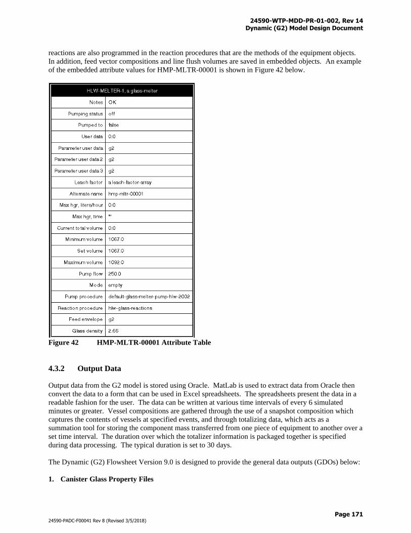
24590-WTP-MDD-PR-01-002, Rev 14 Dynamic (G2) Model Design Document
Page 171
24590-PADC-F00041 Rev 8 (Revised 3/5/2018)
reactions are also programmed in the reaction procedures that are the methods of the equipment objects.
In addition, feed vector compositions and line flush volumes are saved in embedded objects. An example
of the embedded attribute values for HMP-MLTR-00001 is shown in Figure 42 below.
Figure 42 HMP-MLTR-00001 Attribute Table
4.3.2 Output Data
Output data from the G2 model is stored using Oracle. MatLab is used to extract data from Oracle then
convert the data to a form that can be used in Excel spreadsheets. The spreadsheets present the data in a
readable fashion for the user. The data can be written at various time intervals of every 6 simulated
minutes or greater. Vessel compositions are gathered through the use of a snapshot composition which
captures the contents of vessels at specified events, and through totalizing data, which acts as a
summation tool for storing the component mass transferred from one piece of equipment to another over a
set time interval. The duration over which the totalizer information is packaged together is specified
during data processing. The typical duration is set to 30 days.
The Dynamic (G2) Flowsheet Version 9.0 is designed to provide the general data outputs (GDOs) below:
1. Canister Glass Property Files
24590-WTP-MDD-PR-01-002, Rev 14 Dynamic (G2) Model Design Document
Page 172
24590-PADC-F00041 Rev 8 (Revised 3/5/2018)
The canister glass property files are made up of *.csv data files for both ILAW and IHLW canisters
that documents the Simulation Date, Glass Volume (m^3), Glass Mass (kg), Cs-137 (Ci/m^3), Sr-90
(Ci/m^3), Tc-99 (Ci/m^3), transuranic elements (TRU) (nCi/g), and heat loading rate (HLR) (W) of
each canister. Also included in the glass property files are *.jpg files that show the *.csv data over
time for the desired glass type.
2. Evaporator Concentrate Data
The sodium molarity and specific gravity (SpG) vs. time plots for waste feed evaporation process
(FEP), treated LAW evaporation process (TLP), and effluent management facility (EMF) evaporator
bottoms are provided on a yearly basis for the entire model run duration
3. Final Screen Shot
The final screen shot is a screen print *.png of the G2 model user interface at the completion of the
run. The immobilized low-activity waste (ILAW) container counts, immobilized high-level waste
(IHLW) canister counts, and effluent volume to alternate LAW are visible on this image, as is the
simulated model run end date.
4. Hydrogen Generation Rate Data
Hydrogen generation rate (HGR) plots are created on a yearly basis for specific vessels where
hydrogen gas formation was identified to be of concern.
5. LCP Glass Property Data
LCP glass property data provides the waste loadings and glass former additions calculated at LCP-
VSL-00001/2 when the vessels are sampled. The waste loadings in kilograms include: Al2O3, B2O3,
CaO, Cr2O3, Fe2O3, K2O, Li2O, MgO, Na2O, SiO2, TiO2, ZnO, ZrO2, Cs2O, SrO, and Tc2O7.
The glass former additions in kilograms consist of: Al2O3, C12H22O11, B2O3, CaO, Fe2O3, Li2O,
MgO, Na2O, SiO2, TiO2, ZnO, and ZrO2.
6. Flowsheet Mass Balance Diagrams
The flowsheet mass balance diagrams utilize the totalizer data files to create a model run duration
mass balance spreadsheet for all major systems. In addition to an overall spreadsheet, there are
individual spreadsheets and diagrams for: total mass, total volume, radionuclides, Al, Cr, Fe, Na,
C2O4, Cs137, Sr90, I129, Tc99, Hg, H2O, AFA, PO4, Cl, F, SO4, and C10H8.
7. Run Summary Data
The output file “End-Mission-Summaries.csv” includes all of the summary information for the model
run, including: feed vector summary information, key assessment results, annual production
summary, and flowsheet analysis parameters. This file can be compared side by side for various
model runs to see major differences in process data.
8. Snapshot Composition Data
Snapshot composition data was collected at designated points of interests based on the Integrated
Sampling and Analysis Requirements Document (ISARD) and Research and Technology
requirements.
9. Feed Vector File
Contains the feed vector and leach factor files used for the model run. The feed vector and leach
factor data are saved in two Microsoft Access database tables for import to G2.
24590-WTP-MDD-PR-01-002, Rev 14 Dynamic (G2) Model Design Document
Page 173
24590-PADC-F00041 Rev 8 (Revised 3/5/2018)
The feed vector table consists of the planned Tank Farm batch delivery dates, batch type, batch
names, waste component names, and quantities of liquid and solid components in kg-moles. The
leach factor table contains the batch names and the associated leach factors for the solid components
of Al+3, Bi+3, Ca+2, Cr(Total), Fe+3, Na+, PO4-3, Si+4, U (all isotopes), and SO4
-2.
10. Tank Farm Batch Delivery Data
The Tank Farm batch delivery data includes the batch names, delivery date provided by the Tank
Farm, date and time the batches were accepted by the WTP, and the volume, sodium molarity, SpG,
and wt % solids for each batch.
11. Totalizer Data for Process Streams
The totalizer data provides the cumulative mass in kilograms for every process stream in a 30-day
time interval. The process streams are identified by the following convention:
“upstream_downstream.csv”. The data includes the mass in the liquid phase, solid phase, gas phase,
and in the oxide form as appropriate.
12. Volume and Sodium Molarity vs. Time Plots for Process Vessels
The volume and sodium molarity vs. time for the process vessels are provided on a yearly basis for
the model run. The plots were generated using the 30-minute time interval volume history data,
specified above.
13. Volume and Weight Percent Solids vs. Time Plots for Process Vessels
The volume and wt % solids vs. time for the process vessels are provided on a yearly basis for the
model run.
14. Volume History Data for Process Vessels
Volume history data is recorded every 30 minutes within the model and is used to generate the wt %
solids, sodium molarity, and evaporator plots for the model runs.
15. Volume History Plots for LAW and HLW Glass
Cumulative volumes for the model run are provided for the LAW and HLW glasses. These include
the glass volume production, as well as the container and canister counts for the LAW and HLW
melters. Both the plots (*.jpg) and the data used to generate the plots (*.csv).
A model run can provide data from none of the above to all of the above depending on model run
scenarios. In addition to the general data output, supplemental data outputs (SDO) can also be gathered
as needed.
Appendix Q shows the configuration control of the lock down files which contain the source codes of the
Dynamic (G2) Model.
24590-WTP-MDD-PR-01-002, Rev 14 Dynamic (G2) Model Design Document
Page 174
24590-PADC-F00041 Rev 8 (Revised 3/5/2018)
4.4 G2 Mass Balance Calculator
Microsoft Visual Studio 2010 is used for the development of automation tools for the pre- and post- G2
run data manipulation and processing. The Visual C# programming language is selected because of: a) its
Commercial of the Shelf (COTS) nature on the WTP baseline, b) its features for multi-layered graphical
user interface, c) its native functions to interact with Excel spreadsheet, and d) its ability for
modularization. Microsoft Visual Studio 2010 is installed on the WTP virtual machine by the
Information System and Technology (IS&T).
The Visual C# application is named “G2 Mass Balance Calculator” or G2MBC for short. G2MBC
consists of three modules:
1. Feed Vector Conversion – is a pre- G2 run application that is used to:
Convert TFC feed vector format to G2 model format
Perform charge balance operations
2. Mass Balance Diagrams – is a post- G2 run application that is used to:
Extract cumulative mass data from totalizer files
Generate mass balance flowsheet diagrams
3. Totalizer Value Extraction – is a post- G2 run application that is use to:
Extract cumulative volume data from totalizer files
Generate time vs. volume tables
The modules are developed using three Windows forms which are then merged into a Multiple Document
Interface (MDI) named “G2MBC_GUI”. G2MBC_GUI provides a pull-down menu as shown in Figure
43 where each module application can be launched independently. Programming structures of the three
modules are presented in Table 31 where the routine/subroutine names and functionalities are described.
Figure 44 shows a GUI window for interactive inputs with the Mass Balance Diagrams module. For
output file configuration control purpose, current date from the running computer will be automatically
recorded in the output files. Run information such as MRQ and Scenario numbers are also required as
they will be inserted to name strings of the output files. Different flowsheet diagram templates can be
selected due to historical reasons, for example, mass balance flowsheet diagrams can be generated for the
“Leaching in UFP1” and “Leaching in UFP2” flowsheet options. In G2MBC for G2 Version 9.0, only
the “Unified Flowsheet” option, which includes the operations for DFLAW, is made active.
The “Select Types of Flowsheet Diagram” check boxes provide optional inputs for the mass balance
diagrams to be generated. These optional inputs include:
Cumulative Total Mass
Cumulative Total Volume
Cumulative Radioactivity
Aluminum
Chromium
Iron
Sodium
Oxalate
137-Cs
90-Sr
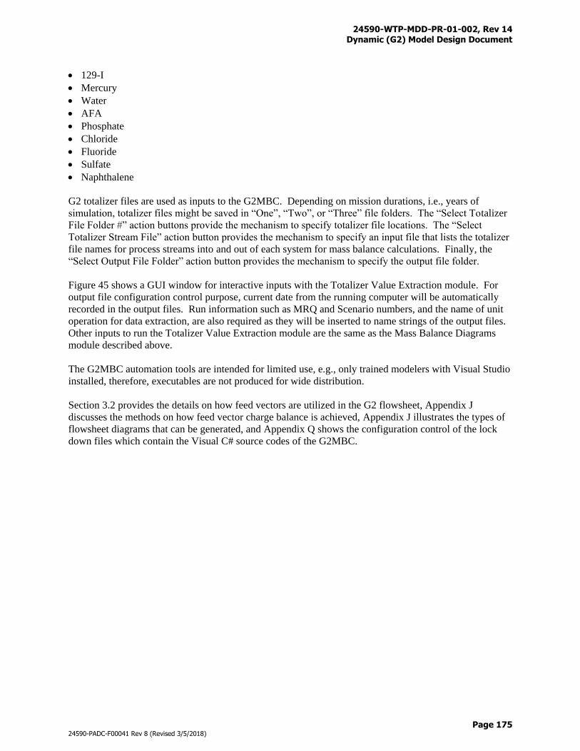
24590-WTP-MDD-PR-01-002, Rev 14 Dynamic (G2) Model Design Document
Page 175
24590-PADC-F00041 Rev 8 (Revised 3/5/2018)
129-I
Mercury
Water
AFA
Phosphate
Chloride
Fluoride
Sulfate
Naphthalene
G2 totalizer files are used as inputs to the G2MBC. Depending on mission durations, i.e., years of
simulation, totalizer files might be saved in “One”, “Two”, or “Three” file folders. The “Select Totalizer
File Folder #” action buttons provide the mechanism to specify totalizer file locations. The “Select
Totalizer Stream File” action button provides the mechanism to specify an input file that lists the totalizer
file names for process streams into and out of each system for mass balance calculations. Finally, the
“Select Output File Folder” action button provides the mechanism to specify the output file folder.
Figure 45 shows a GUI window for interactive inputs with the Totalizer Value Extraction module. For
output file configuration control purpose, current date from the running computer will be automatically
recorded in the output files. Run information such as MRQ and Scenario numbers, and the name of unit
operation for data extraction, are also required as they will be inserted to name strings of the output files.
Other inputs to run the Totalizer Value Extraction module are the same as the Mass Balance Diagrams
module described above.
The G2MBC automation tools are intended for limited use, e.g., only trained modelers with Visual Studio
installed, therefore, executables are not produced for wide distribution.
Section 3.2 provides the details on how feed vectors are utilized in the G2 flowsheet, Appendix J
discusses the methods on how feed vector charge balance is achieved, Appendix J illustrates the types of
flowsheet diagrams that can be generated, and Appendix Q shows the configuration control of the lock
down files which contain the Visual C# source codes of the G2MBC.
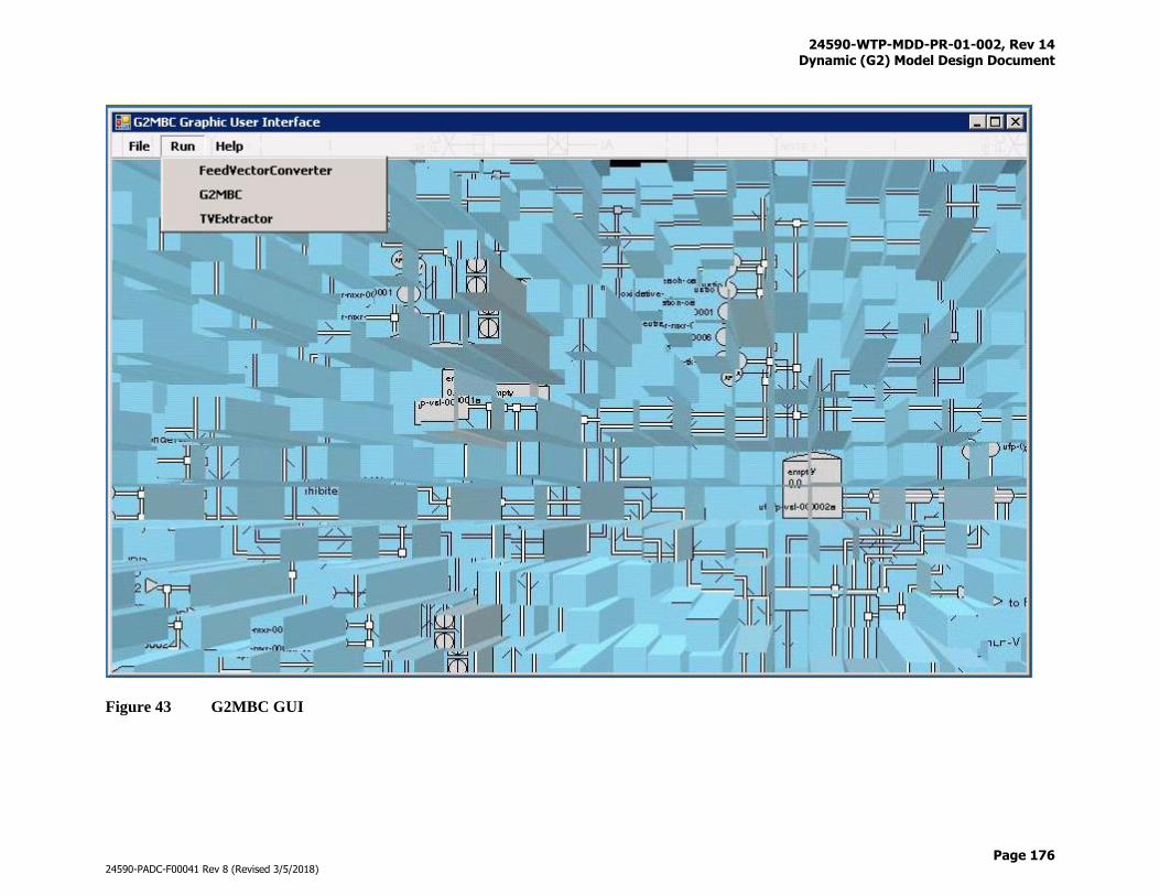
24590-WTP-MDD-PR-01-002, Rev 14 Dynamic (G2) Model Design Document
Page 176
24590-PADC-F00041 Rev 8 (Revised 3/5/2018)
Figure 43 G2MBC GUI
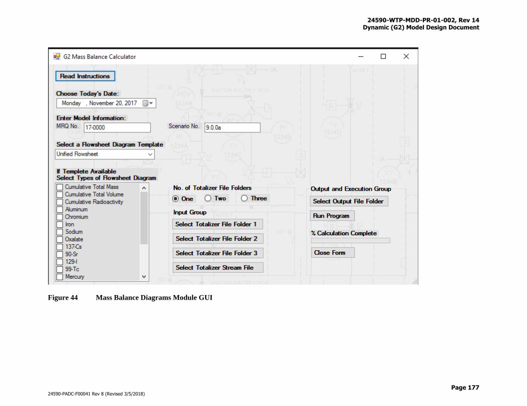
24590-WTP-MDD-PR-01-002, Rev 14 Dynamic (G2) Model Design Document
Page 177
24590-PADC-F00041 Rev 8 (Revised 3/5/2018)
Figure 44 Mass Balance Diagrams Module GUI
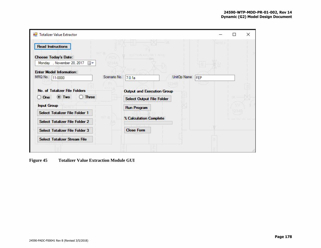
24590-WTP-MDD-PR-01-002, Rev 14 Dynamic (G2) Model Design Document
Page 178
24590-PADC-F00041 Rev 8 (Revised 3/5/2018)
Figure 45 Totalizer Value Extraction Module GUI
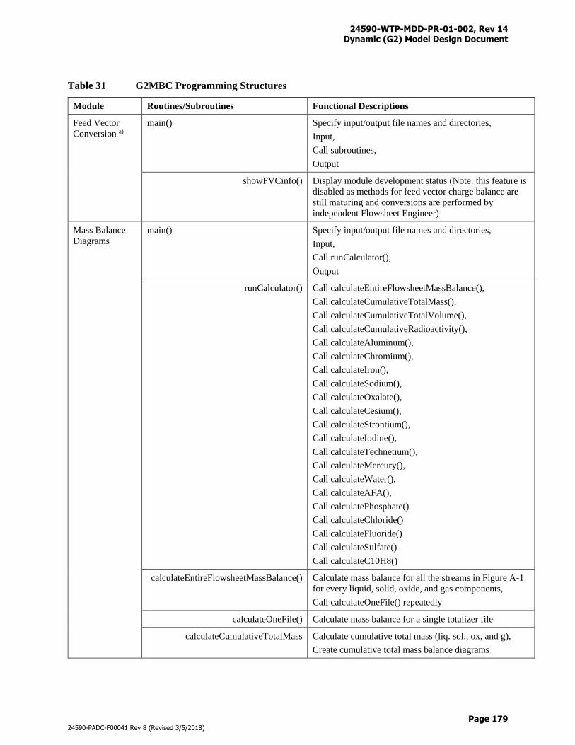
24590-WTP-MDD-PR-01-002, Rev 14 Dynamic (G2) Model Design Document
Page 179
24590-PADC-F00041 Rev 8 (Revised 3/5/2018)
Table 31 G2MBC Programming Structures
Module Routines/Subroutines Functional Descriptions
Feed Vector
Conversion a)
main() Specify input/output file names and directories,
Input,
Call subroutines,
Output
showFVCinfo() Display module development status (Note: this feature is
disabled as methods for feed vector charge balance are
still maturing and conversions are performed by
independent Flowsheet Engineer)
Mass Balance
Diagrams
main() Specify input/output file names and directories,
Input,
Call runCalculator(),
Output
runCalculator() Call calculateEntireFlowsheetMassBalance(),
Call calculateCumulativeTotalMass(),
Call calculateCumulativeTotalVolume(),
Call calculateCumulativeRadioactivity(),
Call calculateAluminum(),
Call calculateChromium(),
Call calculateIron(),
Call calculateSodium(),
Call calculateOxalate(),
Call calculateCesium(),
Call calculateStrontium(),
Call calculateIodine(),
Call calculateTechnetium(),
Call calculateMercury(),
Call calculateWater(),
Call calculateAFA(),
Call calculatePhosphate()
Call calculateChloride()
Call calculateFluoride()
Call calculateSulfate()
Call calculateC10H8()
calculateEntireFlowsheetMassBalance() Calculate mass balance for all the streams in Figure A-1
for every liquid, solid, oxide, and gas components,
Call calculateOneFile() repeatedly
calculateOneFile() Calculate mass balance for a single totalizer file
calculateCumulativeTotalMass Calculate cumulative total mass (liq. sol., ox, and g),
Create cumulative total mass balance diagrams
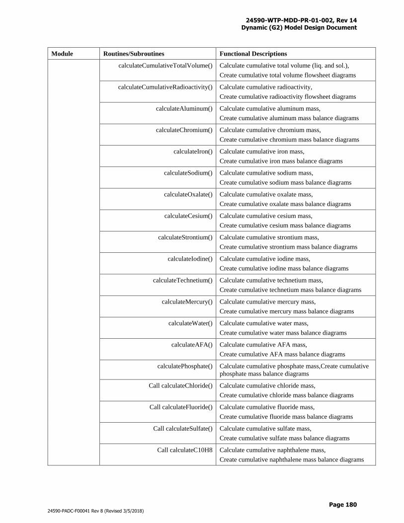
24590-WTP-MDD-PR-01-002, Rev 14 Dynamic (G2) Model Design Document
Page 180
24590-PADC-F00041 Rev 8 (Revised 3/5/2018)
Module Routines/Subroutines Functional Descriptions
calculateCumulativeTotalVolume() Calculate cumulative total volume (liq. and sol.),
Create cumulative total volume flowsheet diagrams
calculateCumulativeRadioactivity() Calculate cumulative radioactivity,
Create cumulative radioactivity flowsheet diagrams
calculateAluminum() Calculate cumulative aluminum mass,
Create cumulative aluminum mass balance diagrams
calculateChromium() Calculate cumulative chromium mass,
Create cumulative chromium mass balance diagrams
calculateIron() Calculate cumulative iron mass,
Create cumulative iron mass balance diagrams
calculateSodium() Calculate cumulative sodium mass,
Create cumulative sodium mass balance diagrams
calculateOxalate() Calculate cumulative oxalate mass,
Create cumulative oxalate mass balance diagrams
calculateCesium() Calculate cumulative cesium mass,
Create cumulative cesium mass balance diagrams
calculateStrontium() Calculate cumulative strontium mass,
Create cumulative strontium mass balance diagrams
calculateIodine() Calculate cumulative iodine mass,
Create cumulative iodine mass balance diagrams
calculateTechnetium() Calculate cumulative technetium mass,
Create cumulative technetium mass balance diagrams
calculateMercury() Calculate cumulative mercury mass,
Create cumulative mercury mass balance diagrams
calculateWater() Calculate cumulative water mass,
Create cumulative water mass balance diagrams
calculateAFA() Calculate cumulative AFA mass,
Create cumulative AFA mass balance diagrams
calculatePhosphate() Calculate cumulative phosphate mass,Create cumulative
phosphate mass balance diagrams
Call calculateChloride() Calculate cumulative chloride mass,
Create cumulative chloride mass balance diagrams
Call calculateFluoride() Calculate cumulative fluoride mass,
Create cumulative fluoride mass balance diagrams
Call calculateSulfate() Calculate cumulative sulfate mass,
Create cumulative sulfate mass balance diagrams
Call calculateC10H8 Calculate cumulative naphthalene mass,
Create cumulative naphthalene mass balance diagrams
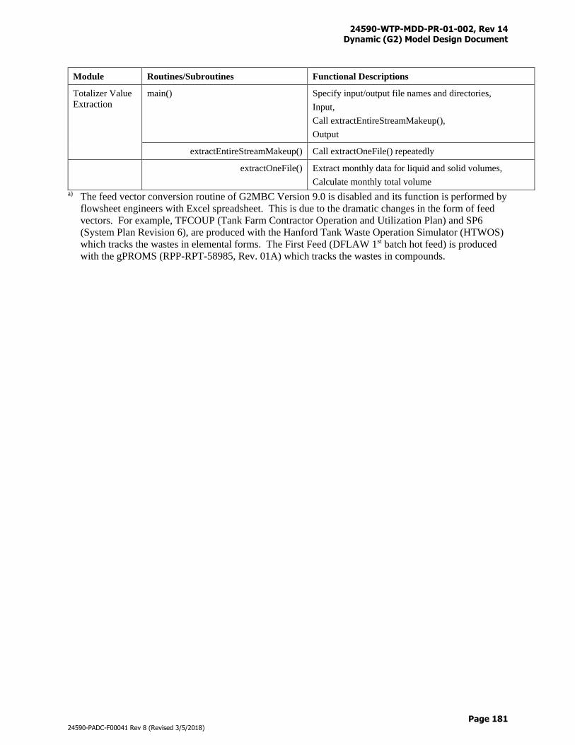
24590-WTP-MDD-PR-01-002, Rev 14 Dynamic (G2) Model Design Document
Page 181
24590-PADC-F00041 Rev 8 (Revised 3/5/2018)
Module Routines/Subroutines Functional Descriptions
Totalizer Value
Extraction
main() Specify input/output file names and directories,
Input,
Call extractEntireStreamMakeup(),
Output
extractEntireStreamMakeup() Call extractOneFile() repeatedly
extractOneFile() Extract monthly data for liquid and solid volumes,
Calculate monthly total volume
a) The feed vector conversion routine of G2MBC Version 9.0 is disabled and its function is performed by
flowsheet engineers with Excel spreadsheet. This is due to the dramatic changes in the form of feed
vectors. For example, TFCOUP (Tank Farm Contractor Operation and Utilization Plan) and SP6
(System Plan Revision 6), are produced with the Hanford Tank Waste Operation Simulator (HTWOS)
which tracks the wastes in elemental forms. The First Feed (DFLAW 1st batch hot feed) is produced
with the gPROMS (RPP-RPT-58985, Rev. 01A) which tracks the wastes in compounds.
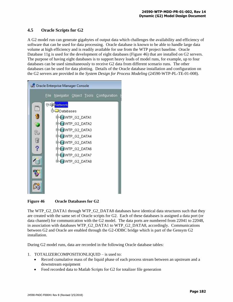
24590-WTP-MDD-PR-01-002, Rev 14 Dynamic (G2) Model Design Document
Page 182
24590-PADC-F00041 Rev 8 (Revised 3/5/2018)
4.5 Oracle Scripts for G2
A G2 model run can generate gigabytes of output data which challenges the availability and efficiency of
software that can be used for data processing. Oracle database is known to be able to handle large data
volume at high efficiency and is readily available for use from the WTP project baseline. Oracle
Database 11g is used for the development of eight databases (Figure 46) that are installed on G2 servers.
The purpose of having eight databases is to support heavy loads of model runs, for example, up to four
databases can be used simultaneously to receive G2 data from different scenario runs. The other
databases can be used for data plotting. Details of the Oracle database installation and configuration on
the G2 servers are provided in the System Design for Process Modeling (24590-WTP-PL-TE-01-008).
Figure 46 Oracle Databases for G2
The WTP_G2_DATA1 through WTP_G2_DATA8 databases have identical data structures such that they
are created with the same set of Oracle scripts for G2. Each of these databases is assigned a data port (or
data channel) for communication with the G2 model. The data ports are numbered from 22041 to 22048,
in association with databases WTP_G2_DATA1 to WTP_G2_DATA8, accordingly. Communications
between G2 and Oracle are enabled through the G2-ODBC bridge which is part of the Gensym G2
installation.
During G2 model runs, data are recorded in the following Oracle database tables:
1. TOTALIZERCOMPOSITIONLIQUID – is used to:
Record cumulative mass of the liquid phase of each process stream between an upstream and a
downstream equipment
Feed recorded data to Matlab Scripts for G2 for totalizer file generation
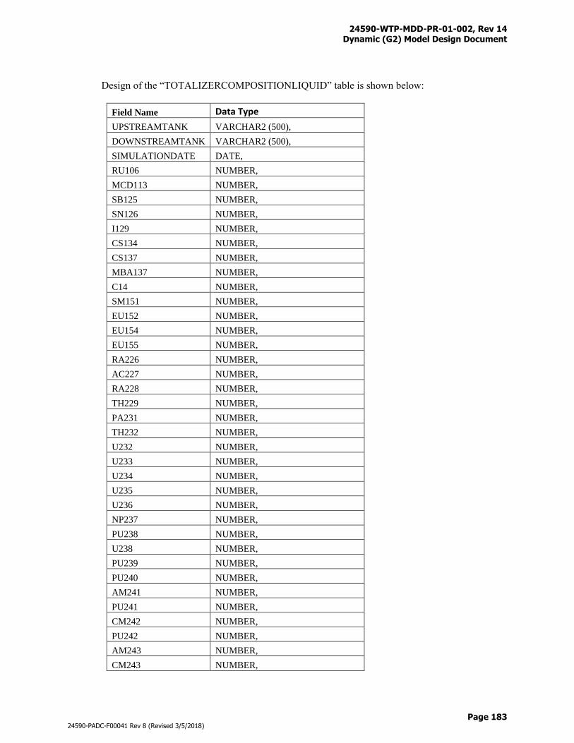
24590-WTP-MDD-PR-01-002, Rev 14 Dynamic (G2) Model Design Document
Page 183
24590-PADC-F00041 Rev 8 (Revised 3/5/2018)
Design of the “TOTALIZERCOMPOSITIONLIQUID” table is shown below:
Field Name Data Type
UPSTREAMTANK VARCHAR2 (500),
DOWNSTREAMTANK VARCHAR2 (500),
SIMULATIONDATE DATE,
RU106 NUMBER,
MCD113 NUMBER,
SB125 NUMBER,
SN126 NUMBER,
I129 NUMBER,
CS134 NUMBER,
CS137 NUMBER,
MBA137 NUMBER,
C14 NUMBER,
SM151 NUMBER,
EU152 NUMBER,
EU154 NUMBER,
EU155 NUMBER,
RA226 NUMBER,
AC227 NUMBER,
RA228 NUMBER,
TH229 NUMBER,
PA231 NUMBER,
TH232 NUMBER,
U232 NUMBER,
U233 NUMBER,
U234 NUMBER,
U235 NUMBER,
U236 NUMBER,
NP237 NUMBER,
PU238 NUMBER,
U238 NUMBER,
PU239 NUMBER,
PU240 NUMBER,
AM241 NUMBER,
PU241 NUMBER,
CM242 NUMBER,
PU242 NUMBER,
AM243 NUMBER,
CM243 NUMBER,
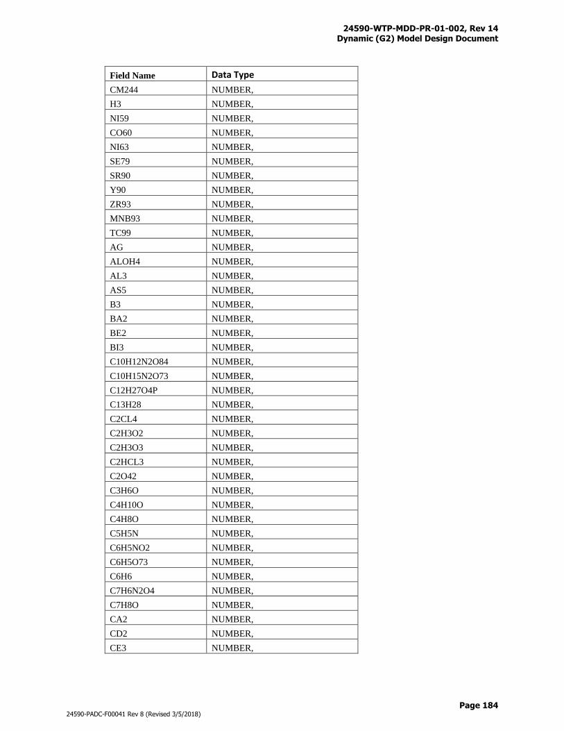
24590-WTP-MDD-PR-01-002, Rev 14 Dynamic (G2) Model Design Document
Page 184
24590-PADC-F00041 Rev 8 (Revised 3/5/2018)
Field Name Data Type
CM244 NUMBER,
H3 NUMBER,
NI59 NUMBER,
CO60 NUMBER,
NI63 NUMBER,
SE79 NUMBER,
SR90 NUMBER,
Y90 NUMBER,
ZR93 NUMBER,
MNB93 NUMBER,
TC99 NUMBER,
AG NUMBER,
ALOH4 NUMBER,
AL3 NUMBER,
AS5 NUMBER,
B3 NUMBER,
BA2 NUMBER,
BE2 NUMBER,
BI3 NUMBER,
C10H12N2O84 NUMBER,
C10H15N2O73 NUMBER,
C12H27O4P NUMBER,
C13H28 NUMBER,
C2CL4 NUMBER,
C2H3O2 NUMBER,
C2H3O3 NUMBER,
C2HCL3 NUMBER,
C2O42 NUMBER,
C3H6O NUMBER,
C4H10O NUMBER,
C4H8O NUMBER,
C5H5N NUMBER,
C6H5NO2 NUMBER,
C6H5O73 NUMBER,
C6H6 NUMBER,
C7H6N2O4 NUMBER,
C7H8O NUMBER,
CA2 NUMBER,
CD2 NUMBER,
CE3 NUMBER,
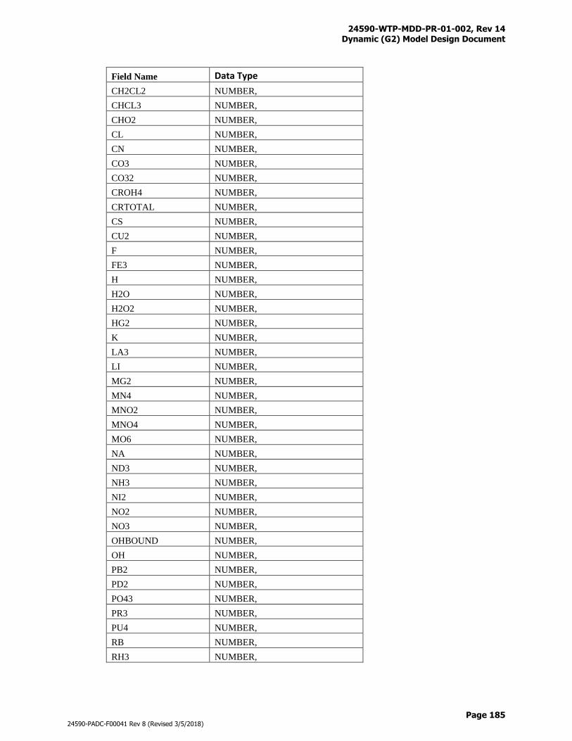
24590-WTP-MDD-PR-01-002, Rev 14 Dynamic (G2) Model Design Document
Page 185
24590-PADC-F00041 Rev 8 (Revised 3/5/2018)
Field Name Data Type
CH2CL2 NUMBER,
CHCL3 NUMBER,
CHO2 NUMBER,
CL NUMBER,
CN NUMBER,
CO3 NUMBER,
CO32 NUMBER,
CROH4 NUMBER,
CRTOTAL NUMBER,
CS NUMBER,
CU2 NUMBER,
F NUMBER,
FE3 NUMBER,
H NUMBER,
H2O NUMBER,
H2O2 NUMBER,
HG2 NUMBER,
K NUMBER,
LA3 NUMBER,
LI NUMBER,
MG2 NUMBER,
MN4 NUMBER,
MNO2 NUMBER,
MNO4 NUMBER,
MO6 NUMBER,
NA NUMBER,
ND3 NUMBER,
NH3 NUMBER,
NI2 NUMBER,
NO2 NUMBER,
NO3 NUMBER,
OHBOUND NUMBER,
OH NUMBER,
PB2 NUMBER,
PD2 NUMBER,
PO43 NUMBER,
PR3 NUMBER,
PU4 NUMBER,
RB NUMBER,
RH3 NUMBER,
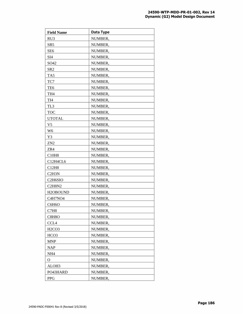
24590-WTP-MDD-PR-01-002, Rev 14 Dynamic (G2) Model Design Document
Page 186
24590-PADC-F00041 Rev 8 (Revised 3/5/2018)
Field Name Data Type
RU3 NUMBER,
SB5 NUMBER,
SE6 NUMBER,
SI4 NUMBER,
SO42 NUMBER,
SR2 NUMBER,
TA5 NUMBER,
TC7 NUMBER,
TE6 NUMBER,
TH4 NUMBER,
TI4 NUMBER,
TL3 NUMBER,
TOC NUMBER,
UTOTAL NUMBER,
V5 NUMBER,
W6 NUMBER,
Y3 NUMBER,
ZN2 NUMBER,
ZR4 NUMBER,
C10H8 NUMBER,
C12H4CL6 NUMBER,
C12H8 NUMBER,
C2H3N NUMBER,
C2H6SIO NUMBER,
C2H8N2 NUMBER,
H2OBOUND NUMBER,
C4H7NO4 NUMBER,
C6H6O NUMBER,
C7H8 NUMBER,
C8H8O NUMBER,
CCL4 NUMBER,
H2CO3 NUMBER,
HCO3 NUMBER,
MNP NUMBER,
NAP NUMBER,
NH4 NUMBER,
O NUMBER,
ALOH3 NUMBER,
PO43HARD NUMBER,
PPG NUMBER,
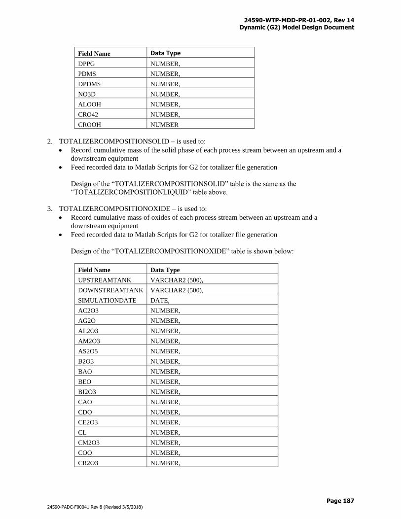
24590-WTP-MDD-PR-01-002, Rev 14 Dynamic (G2) Model Design Document
Page 187
24590-PADC-F00041 Rev 8 (Revised 3/5/2018)
Field Name Data Type
DPPG NUMBER,
PDMS NUMBER,
DPDMS NUMBER,
NO3D NUMBER,
ALOOH NUMBER,
CRO42 NUMBER,
CROOH NUMBER
2. TOTALIZERCOMPOSITIONSOLID – is used to:
Record cumulative mass of the solid phase of each process stream between an upstream and a
downstream equipment
Feed recorded data to Matlab Scripts for G2 for totalizer file generation
Design of the “TOTALIZERCOMPOSITIONSOLID” table is the same as the
“TOTALIZERCOMPOSITIONLIQUID” table above.
3. TOTALIZERCOMPOSITIONOXIDE – is used to:
Record cumulative mass of oxides of each process stream between an upstream and a
downstream equipment
Feed recorded data to Matlab Scripts for G2 for totalizer file generation
Design of the “TOTALIZERCOMPOSITIONOXIDE” table is shown below:
Field Name Data Type
UPSTREAMTANK VARCHAR2 (500),
DOWNSTREAMTANK VARCHAR2 (500),
SIMULATIONDATE DATE,
AC2O3 NUMBER,
AG2O NUMBER,
AL2O3 NUMBER,
AM2O3 NUMBER,
AS2O5 NUMBER,
B2O3 NUMBER,
BAO NUMBER,
BEO NUMBER,
BI2O3 NUMBER,
CAO NUMBER,
CDO NUMBER,
CE2O3 NUMBER,
CL NUMBER,
CM2O3 NUMBER,
COO NUMBER,
CR2O3 NUMBER,
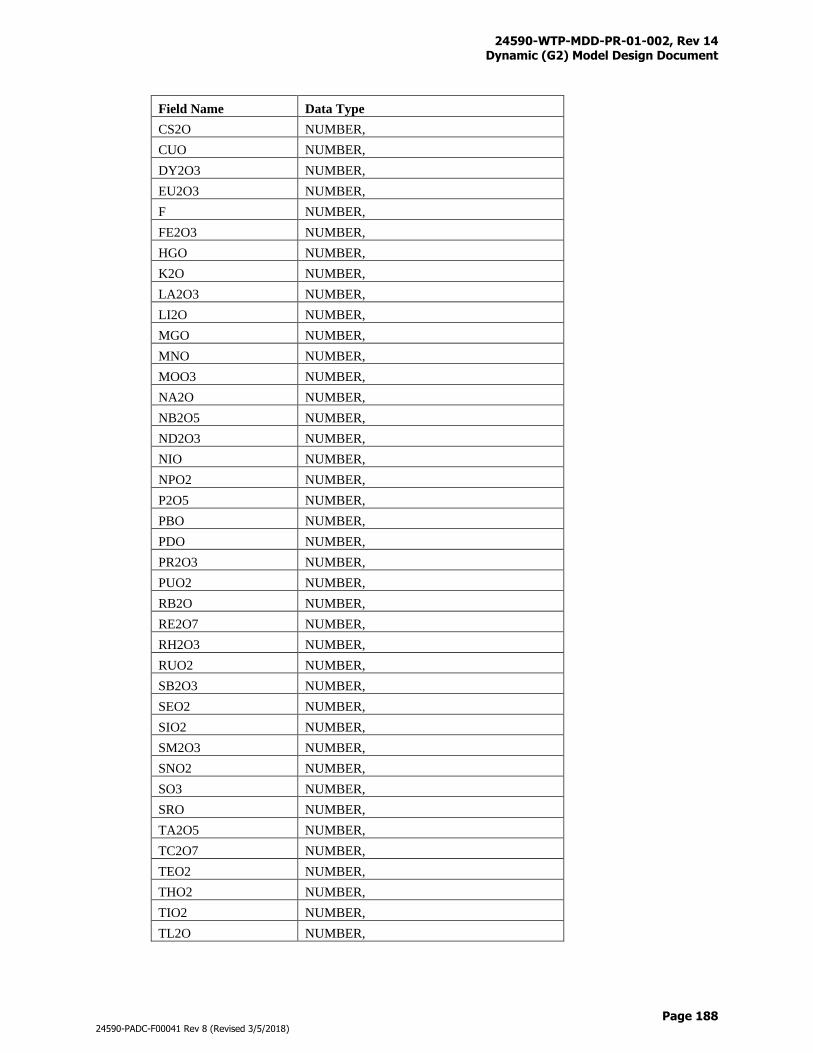
24590-WTP-MDD-PR-01-002, Rev 14 Dynamic (G2) Model Design Document
Page 188
24590-PADC-F00041 Rev 8 (Revised 3/5/2018)
Field Name Data Type
CS2O NUMBER,
CUO NUMBER,
DY2O3 NUMBER,
EU2O3 NUMBER,
F NUMBER,
FE2O3 NUMBER,
HGO NUMBER,
K2O NUMBER,
LA2O3 NUMBER,
LI2O NUMBER,
MGO NUMBER,
MNO NUMBER,
MOO3 NUMBER,
NA2O NUMBER,
NB2O5 NUMBER,
ND2O3 NUMBER,
NIO NUMBER,
NPO2 NUMBER,
P2O5 NUMBER,
PBO NUMBER,
PDO NUMBER,
PR2O3 NUMBER,
PUO2 NUMBER,
RB2O NUMBER,
RE2O7 NUMBER,
RH2O3 NUMBER,
RUO2 NUMBER,
SB2O3 NUMBER,
SEO2 NUMBER,
SIO2 NUMBER,
SM2O3 NUMBER,
SNO2 NUMBER,
SO3 NUMBER,
SRO NUMBER,
TA2O5 NUMBER,
TC2O7 NUMBER,
TEO2 NUMBER,
THO2 NUMBER,
TIO2 NUMBER,
TL2O NUMBER,
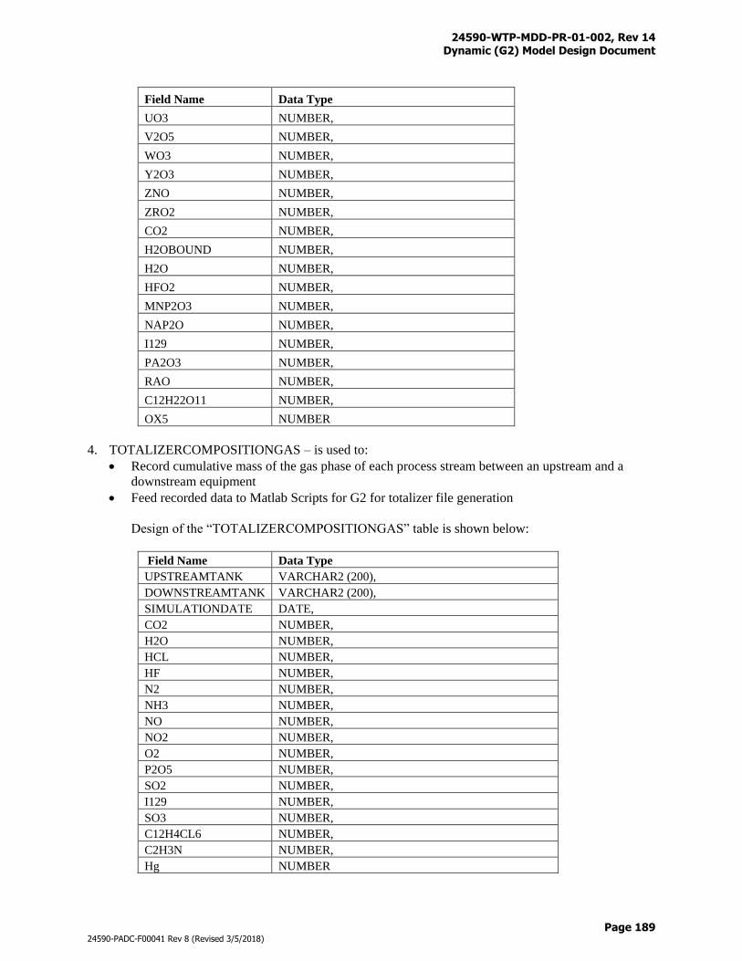
24590-WTP-MDD-PR-01-002, Rev 14 Dynamic (G2) Model Design Document
Page 189
24590-PADC-F00041 Rev 8 (Revised 3/5/2018)
Field Name Data Type
UO3 NUMBER,
V2O5 NUMBER,
WO3 NUMBER,
Y2O3 NUMBER,
ZNO NUMBER,
ZRO2 NUMBER,
CO2 NUMBER,
H2OBOUND NUMBER,
H2O NUMBER,
HFO2 NUMBER,
MNP2O3 NUMBER,
NAP2O NUMBER,
I129 NUMBER,
PA2O3 NUMBER,
RAO NUMBER,
C12H22O11 NUMBER,
OX5 NUMBER
4. TOTALIZERCOMPOSITIONGAS – is used to:
Record cumulative mass of the gas phase of each process stream between an upstream and a
downstream equipment
Feed recorded data to Matlab Scripts for G2 for totalizer file generation
Design of the “TOTALIZERCOMPOSITIONGAS” table is shown below:
Field Name Data Type
UPSTREAMTANK VARCHAR2 (200),
DOWNSTREAMTANK VARCHAR2 (200),
SIMULATIONDATE DATE,
CO2 NUMBER,
H2O NUMBER,
HCL NUMBER,
HF NUMBER,
N2 NUMBER,
NH3 NUMBER,
NO NUMBER,
NO2 NUMBER,
O2 NUMBER,
P2O5 NUMBER,
SO2 NUMBER,
I129 NUMBER,
SO3 NUMBER,
C12H4CL6 NUMBER,
C2H3N NUMBER,
Hg NUMBER
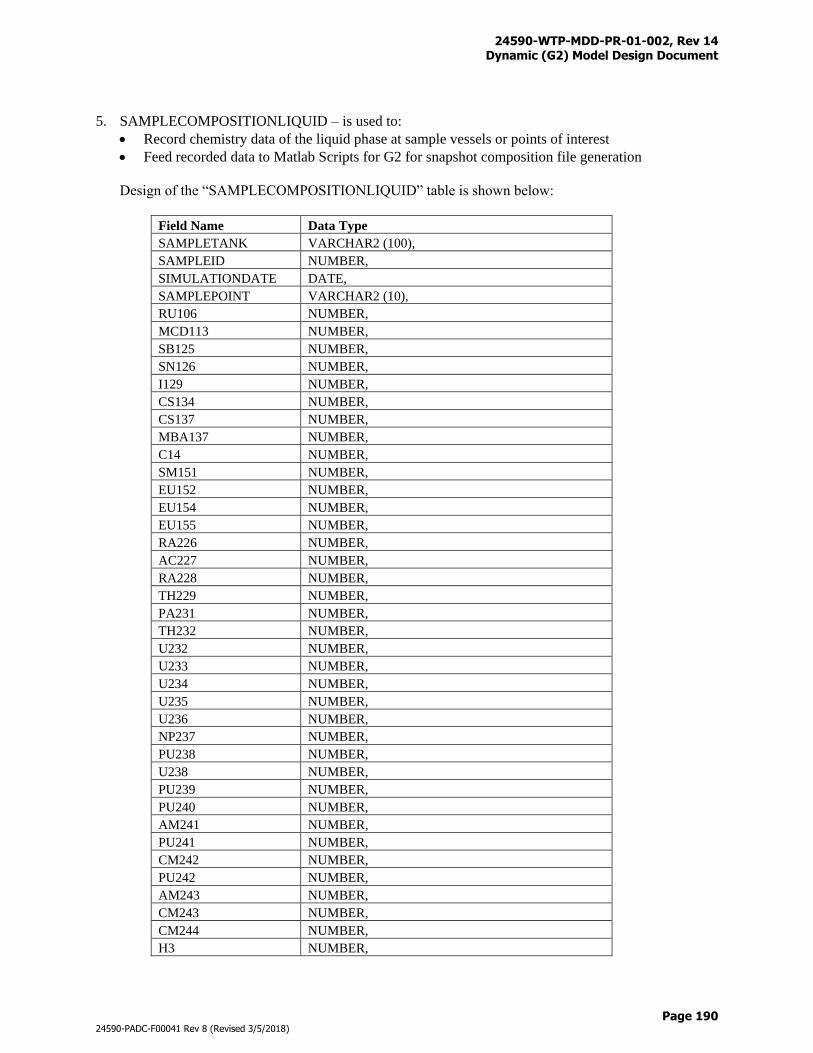
24590-WTP-MDD-PR-01-002, Rev 14 Dynamic (G2) Model Design Document
Page 190
24590-PADC-F00041 Rev 8 (Revised 3/5/2018)
5. SAMPLECOMPOSITIONLIQUID – is used to:
Record chemistry data of the liquid phase at sample vessels or points of interest
Feed recorded data to Matlab Scripts for G2 for snapshot composition file generation
Design of the “SAMPLECOMPOSITIONLIQUID” table is shown below:
Field Name Data Type
SAMPLETANK VARCHAR2 (100),
SAMPLEID NUMBER,
SIMULATIONDATE DATE,
SAMPLEPOINT VARCHAR2 (10),
RU106 NUMBER,
MCD113 NUMBER,
SB125 NUMBER,
SN126 NUMBER,
I129 NUMBER,
CS134 NUMBER,
CS137 NUMBER,
MBA137 NUMBER,
C14 NUMBER,
SM151 NUMBER,
EU152 NUMBER,
EU154 NUMBER,
EU155 NUMBER,
RA226 NUMBER,
AC227 NUMBER,
RA228 NUMBER,
TH229 NUMBER,
PA231 NUMBER,
TH232 NUMBER,
U232 NUMBER,
U233 NUMBER,
U234 NUMBER,
U235 NUMBER,
U236 NUMBER,
NP237 NUMBER,
PU238 NUMBER,
U238 NUMBER,
PU239 NUMBER,
PU240 NUMBER,
AM241 NUMBER,
PU241 NUMBER,
CM242 NUMBER,
PU242 NUMBER,
AM243 NUMBER,
CM243 NUMBER,
CM244 NUMBER,
H3 NUMBER,
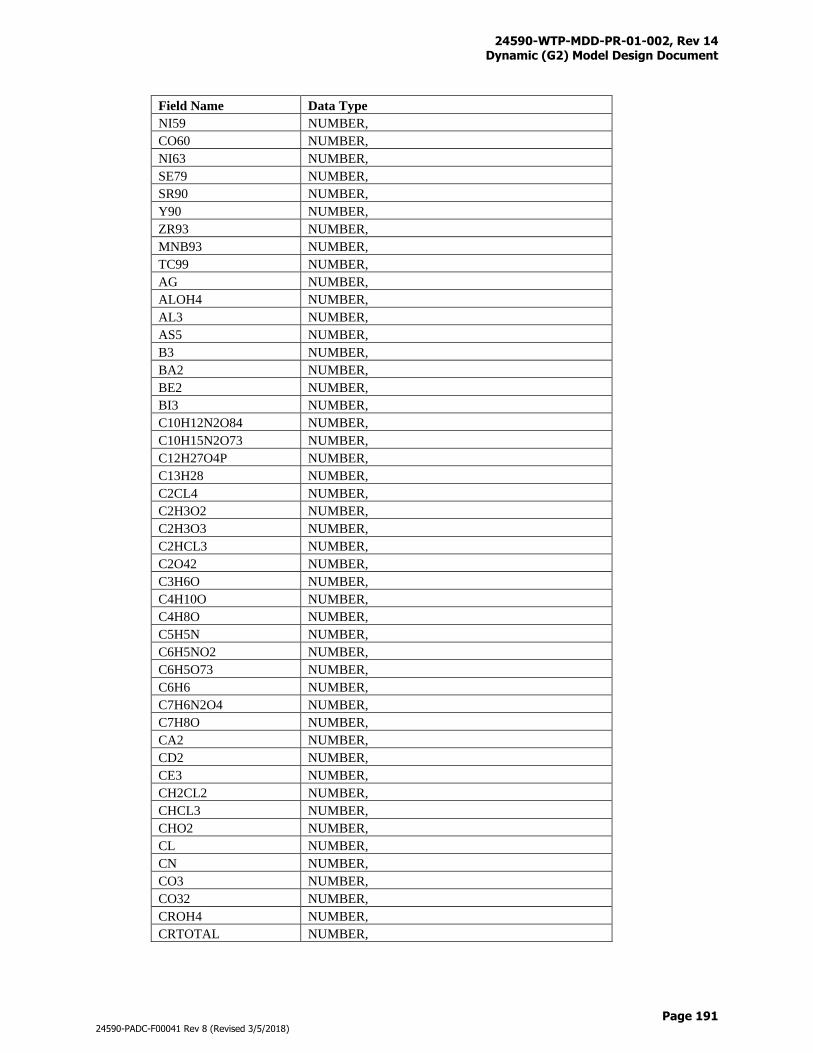
24590-WTP-MDD-PR-01-002, Rev 14 Dynamic (G2) Model Design Document
Page 191
24590-PADC-F00041 Rev 8 (Revised 3/5/2018)
Field Name Data Type
NI59 NUMBER,
CO60 NUMBER,
NI63 NUMBER,
SE79 NUMBER,
SR90 NUMBER,
Y90 NUMBER,
ZR93 NUMBER,
MNB93 NUMBER,
TC99 NUMBER,
AG NUMBER,
ALOH4 NUMBER,
AL3 NUMBER,
AS5 NUMBER,
B3 NUMBER,
BA2 NUMBER,
BE2 NUMBER,
BI3 NUMBER,
C10H12N2O84 NUMBER,
C10H15N2O73 NUMBER,
C12H27O4P NUMBER,
C13H28 NUMBER,
C2CL4 NUMBER,
C2H3O2 NUMBER,
C2H3O3 NUMBER,
C2HCL3 NUMBER,
C2O42 NUMBER,
C3H6O NUMBER,
C4H10O NUMBER,
C4H8O NUMBER,
C5H5N NUMBER,
C6H5NO2 NUMBER,
C6H5O73 NUMBER,
C6H6 NUMBER,
C7H6N2O4 NUMBER,
C7H8O NUMBER,
CA2 NUMBER,
CD2 NUMBER,
CE3 NUMBER,
CH2CL2 NUMBER,
CHCL3 NUMBER,
CHO2 NUMBER,
CL NUMBER,
CN NUMBER,
CO3 NUMBER,
CO32 NUMBER,
CROH4 NUMBER,
CRTOTAL NUMBER,
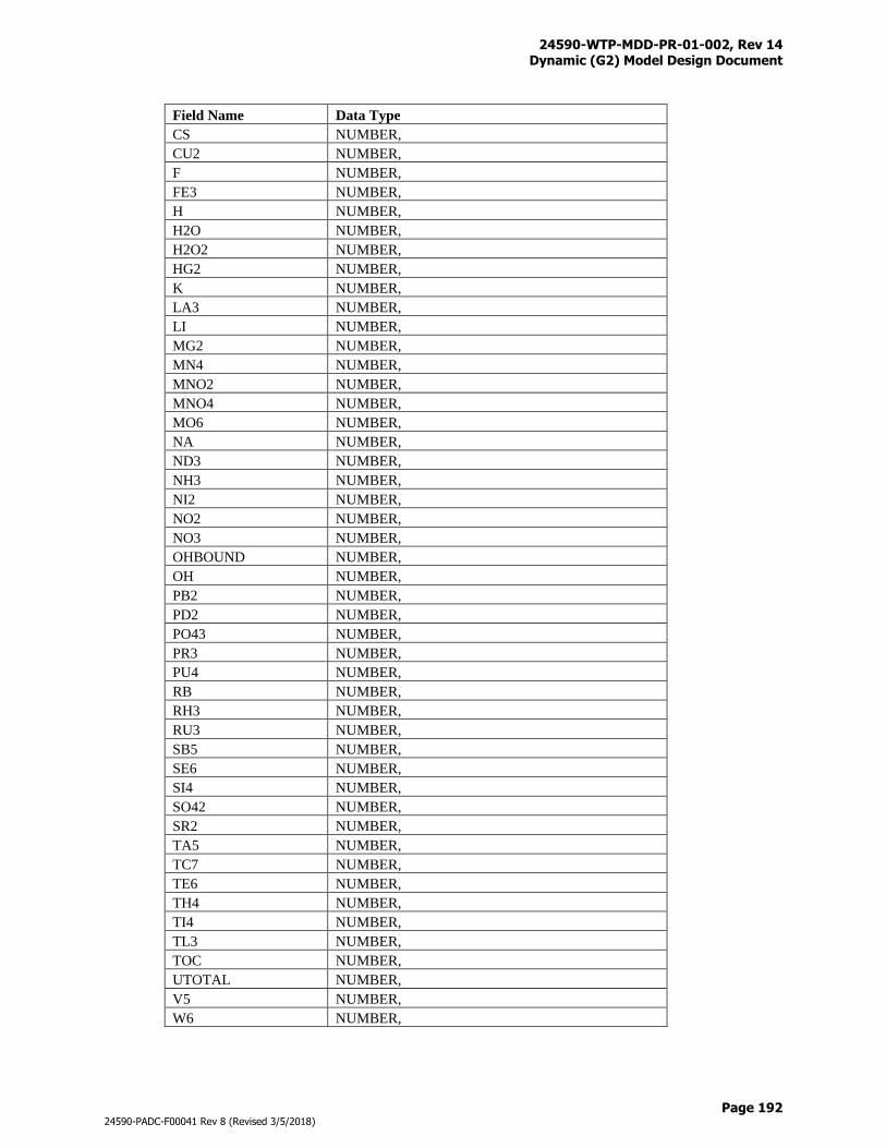
24590-WTP-MDD-PR-01-002, Rev 14 Dynamic (G2) Model Design Document
Page 192
24590-PADC-F00041 Rev 8 (Revised 3/5/2018)
Field Name Data Type
CS NUMBER,
CU2 NUMBER,
F NUMBER,
FE3 NUMBER,
H NUMBER,
H2O NUMBER,
H2O2 NUMBER,
HG2 NUMBER,
K NUMBER,
LA3 NUMBER,
LI NUMBER,
MG2 NUMBER,
MN4 NUMBER,
MNO2 NUMBER,
MNO4 NUMBER,
MO6 NUMBER,
NA NUMBER,
ND3 NUMBER,
NH3 NUMBER,
NI2 NUMBER,
NO2 NUMBER,
NO3 NUMBER,
OHBOUND NUMBER,
OH NUMBER,
PB2 NUMBER,
PD2 NUMBER,
PO43 NUMBER,
PR3 NUMBER,
PU4 NUMBER,
RB NUMBER,
RH3 NUMBER,
RU3 NUMBER,
SB5 NUMBER,
SE6 NUMBER,
SI4 NUMBER,
SO42 NUMBER,
SR2 NUMBER,
TA5 NUMBER,
TC7 NUMBER,
TE6 NUMBER,
TH4 NUMBER,
TI4 NUMBER,
TL3 NUMBER,
TOC NUMBER,
UTOTAL NUMBER,
V5 NUMBER,
W6 NUMBER,
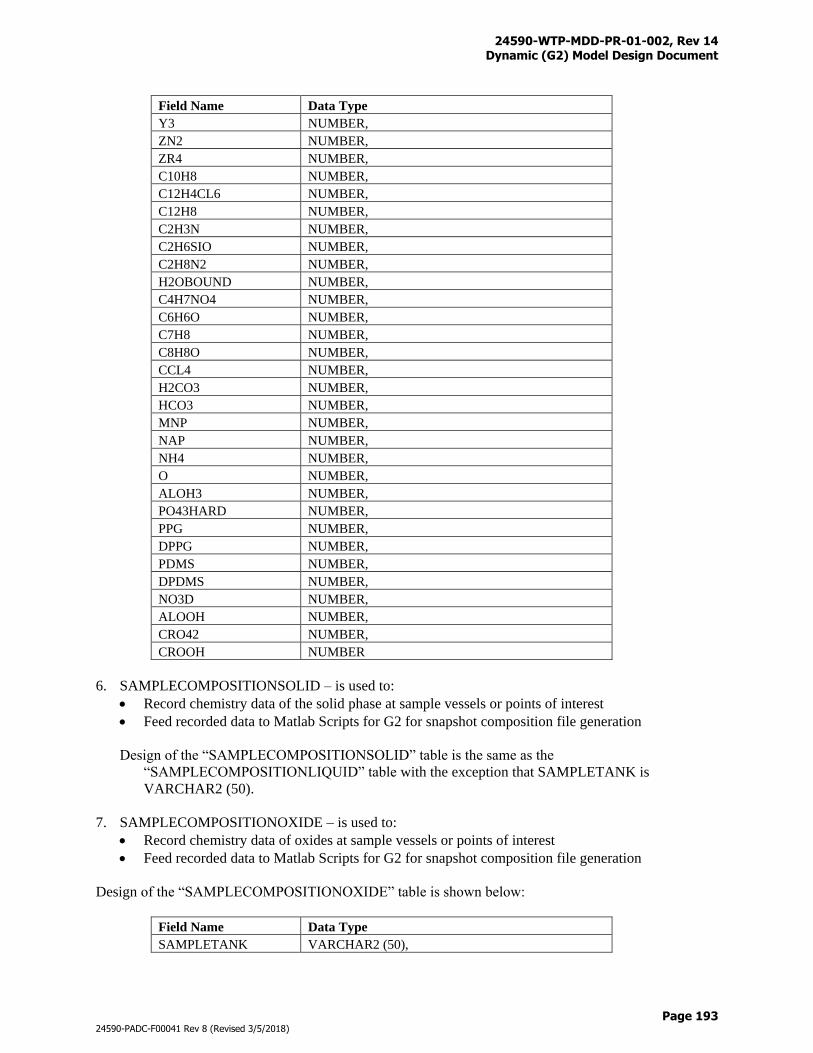
24590-WTP-MDD-PR-01-002, Rev 14 Dynamic (G2) Model Design Document
Page 193
24590-PADC-F00041 Rev 8 (Revised 3/5/2018)
Field Name Data Type
Y3 NUMBER,
ZN2 NUMBER,
ZR4 NUMBER,
C10H8 NUMBER,
C12H4CL6 NUMBER,
C12H8 NUMBER,
C2H3N NUMBER,
C2H6SIO NUMBER,
C2H8N2 NUMBER,
H2OBOUND NUMBER,
C4H7NO4 NUMBER,
C6H6O NUMBER,
C7H8 NUMBER,
C8H8O NUMBER,
CCL4 NUMBER,
H2CO3 NUMBER,
HCO3 NUMBER,
MNP NUMBER,
NAP NUMBER,
NH4 NUMBER,
O NUMBER,
ALOH3 NUMBER,
PO43HARD NUMBER,
PPG NUMBER,
DPPG NUMBER,
PDMS NUMBER,
DPDMS NUMBER,
NO3D NUMBER,
ALOOH NUMBER,
CRO42 NUMBER,
CROOH NUMBER
6. SAMPLECOMPOSITIONSOLID – is used to:
Record chemistry data of the solid phase at sample vessels or points of interest
Feed recorded data to Matlab Scripts for G2 for snapshot composition file generation
Design of the “SAMPLECOMPOSITIONSOLID” table is the same as the
“SAMPLECOMPOSITIONLIQUID” table with the exception that SAMPLETANK is
VARCHAR2 (50).
7. SAMPLECOMPOSITIONOXIDE – is used to:
Record chemistry data of oxides at sample vessels or points of interest
Feed recorded data to Matlab Scripts for G2 for snapshot composition file generation
Design of the “SAMPLECOMPOSITIONOXIDE” table is shown below:
Field Name Data Type
SAMPLETANK VARCHAR2 (50),
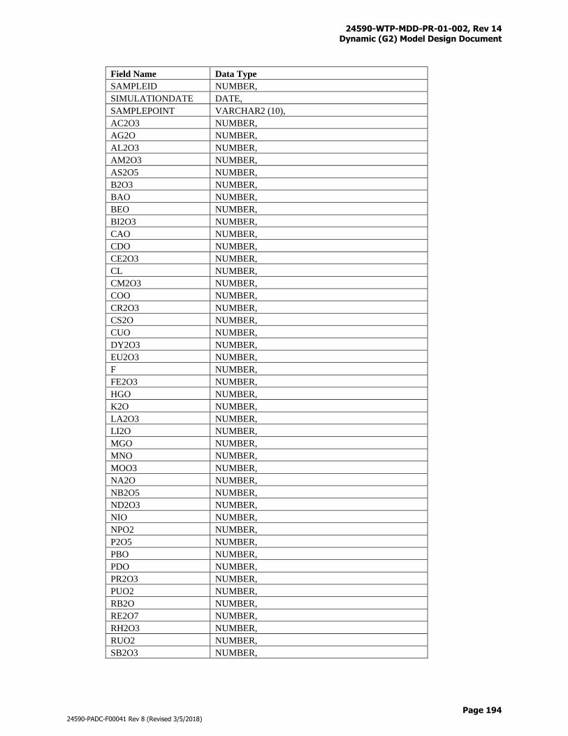
24590-WTP-MDD-PR-01-002, Rev 14 Dynamic (G2) Model Design Document
Page 194
24590-PADC-F00041 Rev 8 (Revised 3/5/2018)
Field Name Data Type
SAMPLEID NUMBER,
SIMULATIONDATE DATE,
SAMPLEPOINT VARCHAR2 (10),
AC2O3 NUMBER,
AG2O NUMBER,
AL2O3 NUMBER,
AM2O3 NUMBER,
AS2O5 NUMBER,
B2O3 NUMBER,
BAO NUMBER,
BEO NUMBER,
BI2O3 NUMBER,
CAO NUMBER,
CDO NUMBER,
CE2O3 NUMBER,
CL NUMBER,
CM2O3 NUMBER,
COO NUMBER,
CR2O3 NUMBER,
CS2O NUMBER,
CUO NUMBER,
DY2O3 NUMBER,
EU2O3 NUMBER,
F NUMBER,
FE2O3 NUMBER,
HGO NUMBER,
K2O NUMBER,
LA2O3 NUMBER,
LI2O NUMBER,
MGO NUMBER,
MNO NUMBER,
MOO3 NUMBER,
NA2O NUMBER,
NB2O5 NUMBER,
ND2O3 NUMBER,
NIO NUMBER,
NPO2 NUMBER,
P2O5 NUMBER,
PBO NUMBER,
PDO NUMBER,
PR2O3 NUMBER,
PUO2 NUMBER,
RB2O NUMBER,
RE2O7 NUMBER,
RH2O3 NUMBER,
RUO2 NUMBER,
SB2O3 NUMBER,
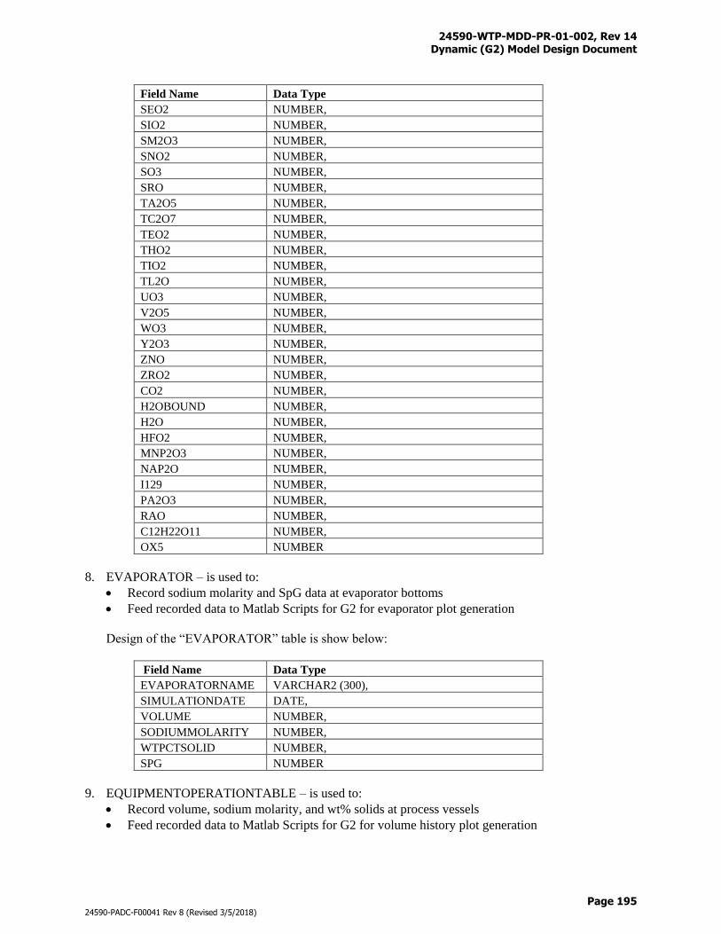
24590-WTP-MDD-PR-01-002, Rev 14 Dynamic (G2) Model Design Document
Page 195
24590-PADC-F00041 Rev 8 (Revised 3/5/2018)
Field Name Data Type
SEO2 NUMBER,
SIO2 NUMBER,
SM2O3 NUMBER,
SNO2 NUMBER,
SO3 NUMBER,
SRO NUMBER,
TA2O5 NUMBER,
TC2O7 NUMBER,
TEO2 NUMBER,
THO2 NUMBER,
TIO2 NUMBER,
TL2O NUMBER,
UO3 NUMBER,
V2O5 NUMBER,
WO3 NUMBER,
Y2O3 NUMBER,
ZNO NUMBER,
ZRO2 NUMBER,
CO2 NUMBER,
H2OBOUND NUMBER,
H2O NUMBER,
HFO2 NUMBER,
MNP2O3 NUMBER,
NAP2O NUMBER,
I129 NUMBER,
PA2O3 NUMBER,
RAO NUMBER,
C12H22O11 NUMBER,
OX5 NUMBER
8. EVAPORATOR – is used to:
Record sodium molarity and SpG data at evaporator bottoms
Feed recorded data to Matlab Scripts for G2 for evaporator plot generation
Design of the “EVAPORATOR” table is show below:
Field Name Data Type
EVAPORATORNAME VARCHAR2 (300),
SIMULATIONDATE DATE,
VOLUME NUMBER,
SODIUMMOLARITY NUMBER,
WTPCTSOLID NUMBER,
SPG NUMBER
9. EQUIPMENTOPERATIONTABLE – is used to:
Record volume, sodium molarity, and wt% solids at process vessels
Feed recorded data to Matlab Scripts for G2 for volume history plot generation
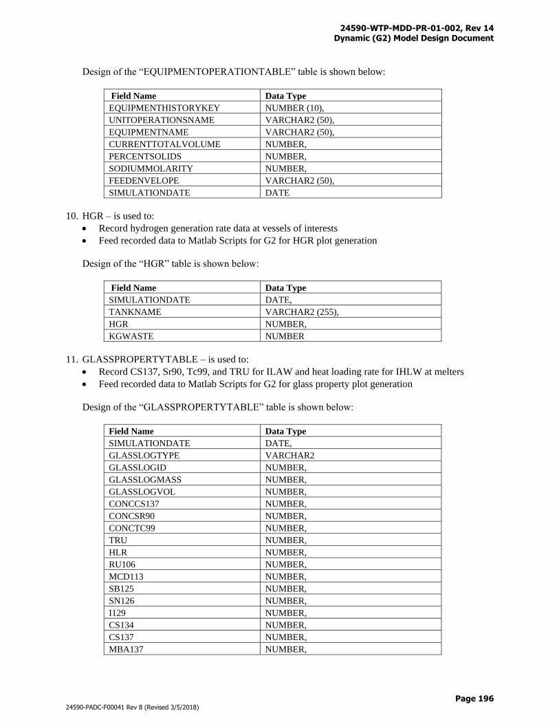
24590-WTP-MDD-PR-01-002, Rev 14 Dynamic (G2) Model Design Document
Page 196
24590-PADC-F00041 Rev 8 (Revised 3/5/2018)
Design of the “EQUIPMENTOPERATIONTABLE” table is shown below:
Field Name Data Type
EQUIPMENTHISTORYKEY NUMBER (10),
UNITOPERATIONSNAME VARCHAR2 (50),
EQUIPMENTNAME VARCHAR2 (50),
CURRENTTOTALVOLUME NUMBER,
PERCENTSOLIDS NUMBER,
SODIUMMOLARITY NUMBER,
FEEDENVELOPE VARCHAR2 (50),
SIMULATIONDATE DATE
10. HGR – is used to:
Record hydrogen generation rate data at vessels of interests
Feed recorded data to Matlab Scripts for G2 for HGR plot generation
Design of the “HGR” table is shown below:
Field Name Data Type
SIMULATIONDATE DATE,
TANKNAME VARCHAR2 (255),
HGR NUMBER,
KGWASTE NUMBER
11. GLASSPROPERTYTABLE – is used to:
Record CS137, Sr90, Tc99, and TRU for ILAW and heat loading rate for IHLW at melters
Feed recorded data to Matlab Scripts for G2 for glass property plot generation
Design of the “GLASSPROPERTYTABLE” table is shown below:
Field Name Data Type
SIMULATIONDATE DATE,
GLASSLOGTYPE VARCHAR2
GLASSLOGID NUMBER,
GLASSLOGMASS NUMBER,
GLASSLOGVOL NUMBER,
CONCCS137 NUMBER,
CONCSR90 NUMBER,
CONCTC99 NUMBER,
TRU NUMBER,
HLR NUMBER,
RU106 NUMBER,
MCD113 NUMBER,
SB125 NUMBER,
SN126 NUMBER,
I129 NUMBER,
CS134 NUMBER,
CS137 NUMBER,
MBA137 NUMBER,
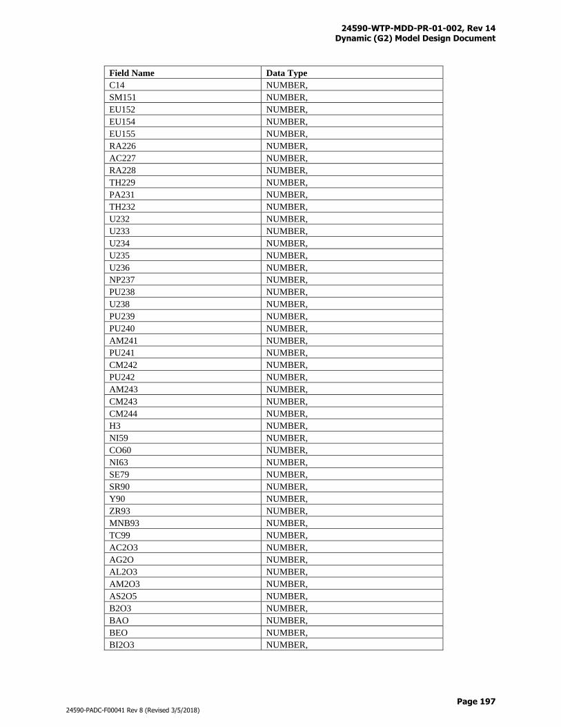
24590-WTP-MDD-PR-01-002, Rev 14 Dynamic (G2) Model Design Document
Page 197
24590-PADC-F00041 Rev 8 (Revised 3/5/2018)
Field Name Data Type
C14 NUMBER,
SM151 NUMBER,
EU152 NUMBER,
EU154 NUMBER,
EU155 NUMBER,
RA226 NUMBER,
AC227 NUMBER,
RA228 NUMBER,
TH229 NUMBER,
PA231 NUMBER,
TH232 NUMBER,
U232 NUMBER,
U233 NUMBER,
U234 NUMBER,
U235 NUMBER,
U236 NUMBER,
NP237 NUMBER,
PU238 NUMBER,
U238 NUMBER,
PU239 NUMBER,
PU240 NUMBER,
AM241 NUMBER,
PU241 NUMBER,
CM242 NUMBER,
PU242 NUMBER,
AM243 NUMBER,
CM243 NUMBER,
CM244 NUMBER,
H3 NUMBER,
NI59 NUMBER,
CO60 NUMBER,
NI63 NUMBER,
SE79 NUMBER,
SR90 NUMBER,
Y90 NUMBER,
ZR93 NUMBER,
MNB93 NUMBER,
TC99 NUMBER,
AC2O3 NUMBER,
AG2O NUMBER,
AL2O3 NUMBER,
AM2O3 NUMBER,
AS2O5 NUMBER,
B2O3 NUMBER,
BAO NUMBER,
BEO NUMBER,
BI2O3 NUMBER,
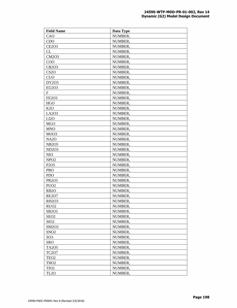
24590-WTP-MDD-PR-01-002, Rev 14 Dynamic (G2) Model Design Document
Page 198
24590-PADC-F00041 Rev 8 (Revised 3/5/2018)
Field Name Data Type
CAO NUMBER,
CDO NUMBER,
CE2O3 NUMBER,
CL NUMBER,
CM2O3 NUMBER,
COO NUMBER,
CR2O3 NUMBER,
CS2O NUMBER,
CUO NUMBER,
DY2O3 NUMBER,
EU2O3 NUMBER,
F NUMBER,
FE2O3 NUMBER,
HGO NUMBER,
K2O NUMBER,
LA2O3 NUMBER,
LI2O NUMBER,
MGO NUMBER,
MNO NUMBER,
MOO3 NUMBER,
NA2O NUMBER,
NB2O5 NUMBER,
ND2O3 NUMBER,
NIO NUMBER,
NPO2 NUMBER,
P2O5 NUMBER,
PBO NUMBER,
PDO NUMBER,
PR2O3 NUMBER,
PUO2 NUMBER,
RB2O NUMBER,
RE2O7 NUMBER,
RH2O3 NUMBER,
RUO2 NUMBER,
SB2O3 NUMBER,
SEO2 NUMBER,
SIO2 NUMBER,
SM2O3 NUMBER,
SNO2 NUMBER,
SO3 NUMBER,
SRO NUMBER,
TA2O5 NUMBER,
TC2O7 NUMBER,
TEO2 NUMBER,
THO2 NUMBER,
TIO2 NUMBER,
TL2O NUMBER,
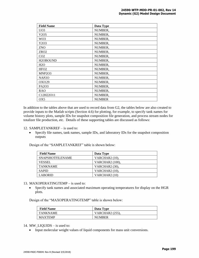
24590-WTP-MDD-PR-01-002, Rev 14 Dynamic (G2) Model Design Document
Page 199
24590-PADC-F00041 Rev 8 (Revised 3/5/2018)
Field Name Data Type
UO3 NUMBER,
V2O5 NUMBER,
WO3 NUMBER,
Y2O3 NUMBER,
ZNO NUMBER,
ZRO2 NUMBER,
CO2 NUMBER,
H2OBOUND NUMBER,
H2O NUMBER,
HFO2 NUMBER,
MNP2O3 NUMBER,
NAP2O NUMBER,
OXI129 NUMBER,
PA2O3 NUMBER,
RAO NUMBER,
C12H22O11 NUMBER,
OX5 NUMBER
In addition to the tables above that are used to record data from G2, the tables below are also created to
provide inputs to the Matlab scripts (Section 4.6) for plotting, for example, to specify tank names for
volume history plots, sample IDs for snapshot composition file generation, and process stream nodes for
totalizer file production, etc. Details of these supporting tables are discussed as follows:
12. SAMPLETANKREF – is used to:
Specify file names, tank names, sample IDs, and laboratory IDs for the snapshot composition
outputs
Design of the “SAMPLETANKREF” table is shown below:
Field Name Data Type
SNAPSHOTFILENAME VARCHAR2 (10),
VESSEL VARCHAR2 (100),
TANKNAME VARCHAR2 (30),
SAPID VARCHAR2 (10),
LABORID VARCHAR2 (10)
13. MAXOPERATINGTEMP – is used to:
Specify tank names and associated maximum operating temperatures for display on the HGR
plots.
Design of the “MAXOPERATINGTEMP” table is shown below:
Field Name Data Type
TANKNAME VARCHAR2 (255),
MAXTEMP NUMBER
14. MW_LIQUIDS – is used to:
Input molecular weight values of liquid components for mass unit conversions.
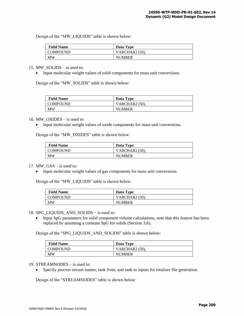
24590-WTP-MDD-PR-01-002, Rev 14 Dynamic (G2) Model Design Document
Page 200
24590-PADC-F00041 Rev 8 (Revised 3/5/2018)
Design of the “MW_LIQUIDS” table is shown below:
Field Name Data Type
COMPOUND VARCHAR2 (50),
MW NUMBER
15. MW_SOLIDS – is used to:
Input molecular weight values of solid components for mass unit conversions.
Design of the “MW_SOLIDS” table is shown below:
Field Name Data Type
COMPOUND VARCHAR2 (50),
MW NUMBER
16. MW_OXIDES – is used to:
Input molecular weight values of oxide components for mass unit conversions.
Design of the “MW_OXIDES” table is shown below:
Field Name Data Type
COMPOUND VARCHAR2 (50),
MW NUMBER
17. MW_GAS – is used to:
Input molecular weight values of gas components for mass unit conversions.
Design of the “MW_LIQUIDS” table is shown below:
Field Name Data Type
COMPOUND VARCHAR2 (50),
MW NUMBER
18. SPG_LIQUIDS_AND_SOLIDS – is used to:
Input SpG parameters for solid component volume calculations, note that this feature has been
replaced by assuming a constant SpG for solids (Section 3.6).
Design of the “SPG_LIQUIDS_AND_SOLIDS” table is shown below:
Field Name Data Type
COMPOUND VARCHAR2 (50),
MW NUMBER
19. STREAMNODES – is used to:
Specify process stream names, tank from, and tank to inputs for totalizer file generation.
Design of the “STREAMNODES” table is shown below:
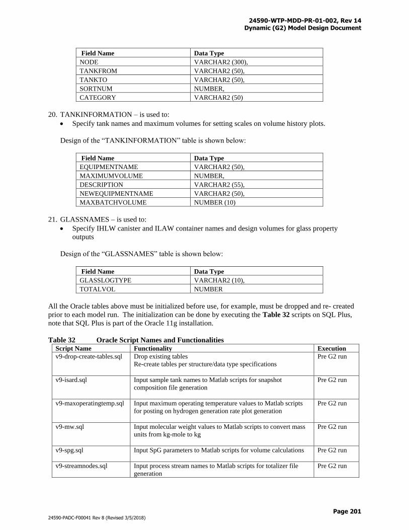
24590-WTP-MDD-PR-01-002, Rev 14 Dynamic (G2) Model Design Document
Page 201
24590-PADC-F00041 Rev 8 (Revised 3/5/2018)
Field Name Data Type
NODE VARCHAR2 (300),
TANKFROM VARCHAR2 (50),
TANKTO VARCHAR2 (50),
SORTNUM NUMBER,
CATEGORY VARCHAR2 (50)
20. TANKINFORMATION – is used to:
Specify tank names and maximum volumes for setting scales on volume history plots.
Design of the “TANKINFORMATION” table is shown below:
Field Name Data Type
EQUIPMENTNAME VARCHAR2 (50),
MAXIMUMVOLUME NUMBER,
DESCRIPTION VARCHAR2 (55),
NEWEQUIPMENTNAME VARCHAR2 (50),
MAXBATCHVOLUME NUMBER (10)
21. GLASSNAMES – is used to:
Specify IHLW canister and ILAW container names and design volumes for glass property
outputs
Design of the “GLASSNAMES” table is shown below:
Field Name Data Type
GLASSLOGTYPE VARCHAR2 (10),
TOTALVOL NUMBER
All the Oracle tables above must be initialized before use, for example, must be dropped and re- created
prior to each model run. The initialization can be done by executing the Table 32 scripts on SQL Plus,
note that SQL Plus is part of the Oracle 11g installation.
Table 32 Oracle Script Names and Functionalities
Script Name Functionality Execution
v9-drop-create-tables.sql Drop existing tables
Re-create tables per structure/data type specifications
Pre G2 run
v9-isard.sql Input sample tank names to Matlab scripts for snapshot
composition file generation
Pre G2 run
v9-maxoperatingtemp.sql Input maximum operating temperature values to Matlab scripts
for posting on hydrogen generation rate plot generation
Pre G2 run
v9-mw.sql Input molecular weight values to Matlab scripts to convert mass
units from kg-mole to kg
Pre G2 run
v9-spg.sql Input SpG parameters to Matlab scripts for volume calculations
Pre G2 run
v9-streamnodes.sql Input process stream names to Matlab scripts for totalizer file
generation
Pre G2 run
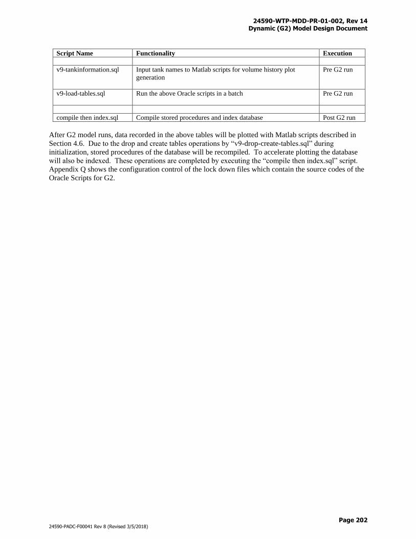
24590-WTP-MDD-PR-01-002, Rev 14 Dynamic (G2) Model Design Document
Page 202
24590-PADC-F00041 Rev 8 (Revised 3/5/2018)
Script Name Functionality Execution
v9-tankinformation.sql Input tank names to Matlab scripts for volume history plot
generation
Pre G2 run
v9-load-tables.sql Run the above Oracle scripts in a batch
Pre G2 run
compile then index.sql Compile stored procedures and index database Post G2 run
After G2 model runs, data recorded in the above tables will be plotted with Matlab scripts described in
Section 4.6. Due to the drop and create tables operations by “v9-drop-create-tables.sql” during
initialization, stored procedures of the database will be recompiled. To accelerate plotting the database
will also be indexed. These operations are completed by executing the “compile then index.sql” script.
Appendix Q shows the configuration control of the lock down files which contain the source codes of the
Oracle Scripts for G2.
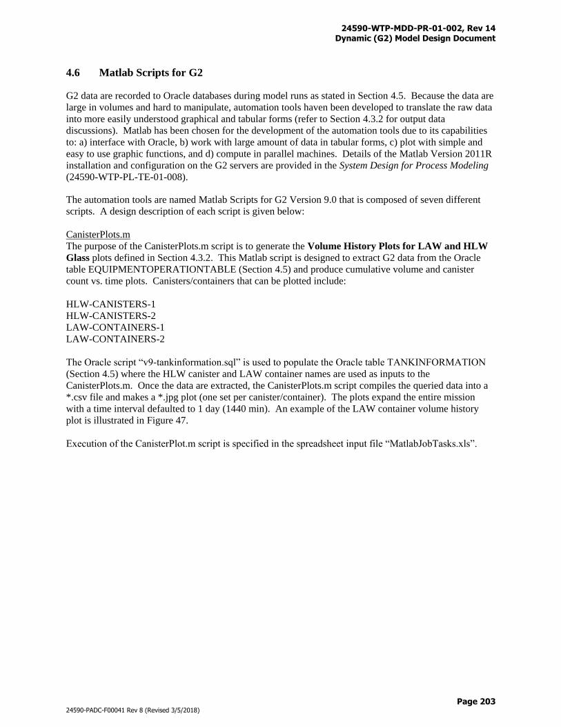
24590-WTP-MDD-PR-01-002, Rev 14 Dynamic (G2) Model Design Document
Page 203
24590-PADC-F00041 Rev 8 (Revised 3/5/2018)
4.6 Matlab Scripts for G2
G2 data are recorded to Oracle databases during model runs as stated in Section 4.5. Because the data are
large in volumes and hard to manipulate, automation tools haven been developed to translate the raw data
into more easily understood graphical and tabular forms (refer to Section 4.3.2 for output data
discussions). Matlab has been chosen for the development of the automation tools due to its capabilities
to: a) interface with Oracle, b) work with large amount of data in tabular forms, c) plot with simple and
easy to use graphic functions, and d) compute in parallel machines. Details of the Matlab Version 2011R
installation and configuration on the G2 servers are provided in the System Design for Process Modeling
(24590-WTP-PL-TE-01-008).
The automation tools are named Matlab Scripts for G2 Version 9.0 that is composed of seven different
scripts. A design description of each script is given below:
CanisterPlots.m
The purpose of the CanisterPlots.m script is to generate the Volume History Plots for LAW and HLW
Glass plots defined in Section 4.3.2. This Matlab script is designed to extract G2 data from the Oracle
table EQUIPMENTOPERATIONTABLE (Section 4.5) and produce cumulative volume and canister
count vs. time plots. Canisters/containers that can be plotted include:
HLW-CANISTERS-1
HLW-CANISTERS-2
LAW-CONTAINERS-1
LAW-CONTAINERS-2
The Oracle script “v9-tankinformation.sql” is used to populate the Oracle table TANKINFORMATION
(Section 4.5) where the HLW canister and LAW container names are used as inputs to the
CanisterPlots.m. Once the data are extracted, the CanisterPlots.m script compiles the queried data into a
*.csv file and makes a *.jpg plot (one set per canister/container). The plots expand the entire mission
with a time interval defaulted to 1 day (1440 min). An example of the LAW container volume history
plot is illustrated in Figure 47.
Execution of the CanisterPlot.m script is specified in the spreadsheet input file “MatlabJobTasks.xls”.
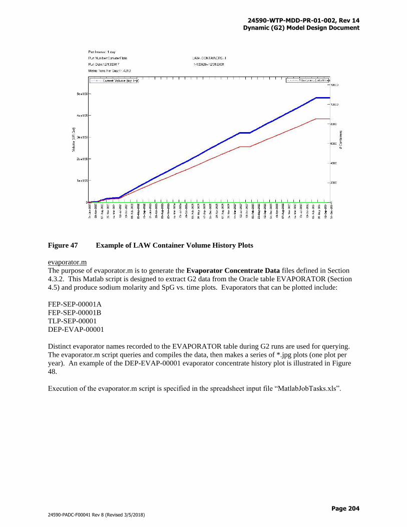
24590-WTP-MDD-PR-01-002, Rev 14 Dynamic (G2) Model Design Document
Page 204
24590-PADC-F00041 Rev 8 (Revised 3/5/2018)
Figure 47 Example of LAW Container Volume History Plots
evaporator.m
The purpose of evaporator.m is to generate the Evaporator Concentrate Data files defined in Section
4.3.2. This Matlab script is designed to extract G2 data from the Oracle table EVAPORATOR (Section
4.5) and produce sodium molarity and SpG vs. time plots. Evaporators that can be plotted include:
FEP-SEP-00001A
FEP-SEP-00001B
TLP-SEP-00001
DEP-EVAP-00001
Distinct evaporator names recorded to the EVAPORATOR table during G2 runs are used for querying.
The evaporator.m script queries and compiles the data, then makes a series of *.jpg plots (one plot per
year). An example of the DEP-EVAP-00001 evaporator concentrate history plot is illustrated in Figure
48.
Execution of the evaporator.m script is specified in the spreadsheet input file “MatlabJobTasks.xls”.
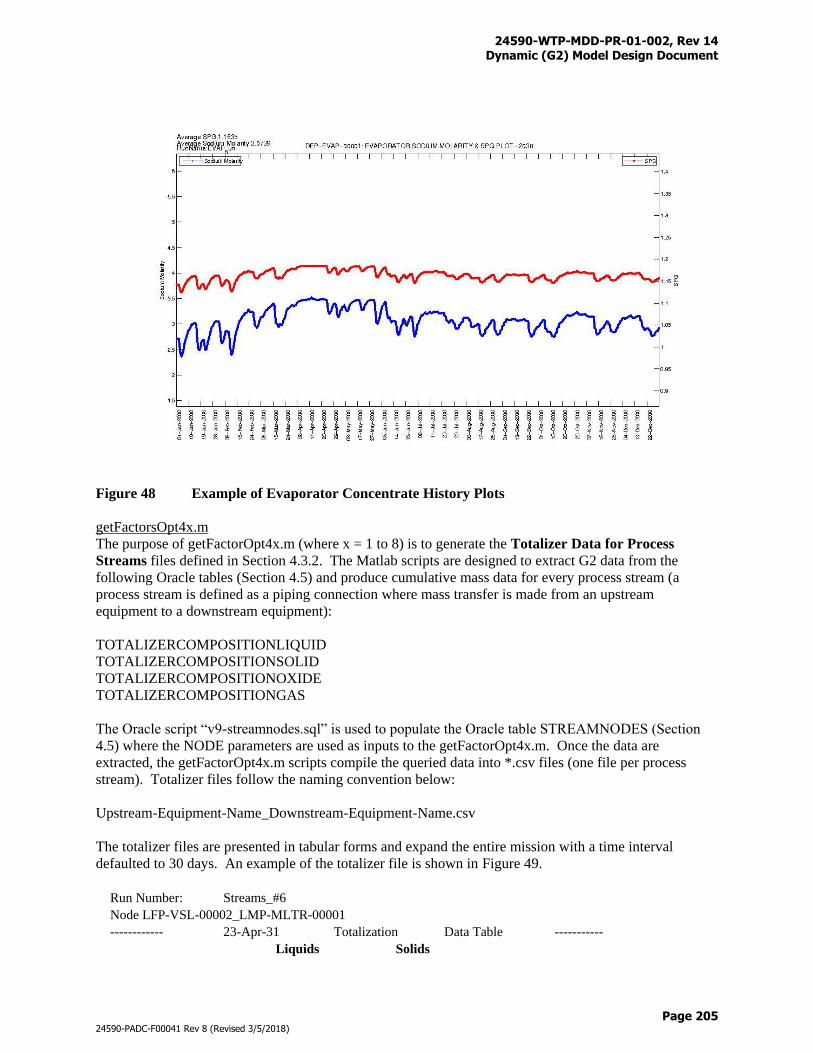
24590-WTP-MDD-PR-01-002, Rev 14 Dynamic (G2) Model Design Document
Page 205
24590-PADC-F00041 Rev 8 (Revised 3/5/2018)
Figure 48 Example of Evaporator Concentrate History Plots
getFactorsOpt4x.m
The purpose of getFactorOpt4x.m (where x = 1 to 8) is to generate the Totalizer Data for Process
Streams files defined in Section 4.3.2. The Matlab scripts are designed to extract G2 data from the
following Oracle tables (Section 4.5) and produce cumulative mass data for every process stream (a
process stream is defined as a piping connection where mass transfer is made from an upstream
equipment to a downstream equipment):
TOTALIZERCOMPOSITIONLIQUID
TOTALIZERCOMPOSITIONSOLID
TOTALIZERCOMPOSITIONOXIDE
TOTALIZERCOMPOSITIONGAS
The Oracle script “v9-streamnodes.sql” is used to populate the Oracle table STREAMNODES (Section
4.5) where the NODE parameters are used as inputs to the getFactorOpt4x.m. Once the data are
extracted, the getFactorOpt4x.m scripts compile the queried data into *.csv files (one file per process
stream). Totalizer files follow the naming convention below:
Upstream-Equipment-Name_Downstream-Equipment-Name.csv
The totalizer files are presented in tabular forms and expand the entire mission with a time interval
defaulted to 30 days. An example of the totalizer file is shown in Figure 49.
Run Number: Streams_#6
Node LFP-VSL-00002_LMP-MLTR-00001
------------ 23-Apr-31 Totalization Data Table -----------
Liquids Solids
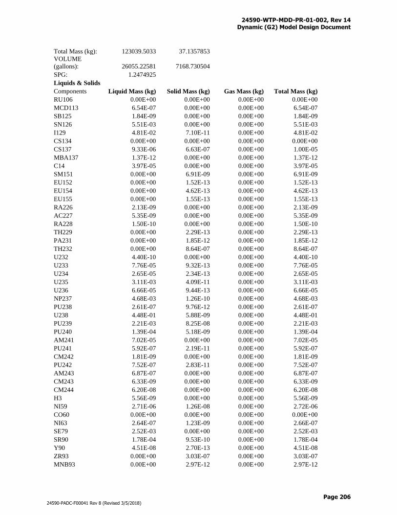
24590-WTP-MDD-PR-01-002, Rev 14 Dynamic (G2) Model Design Document
Page 206
24590-PADC-F00041 Rev 8 (Revised 3/5/2018)
Total Mass (kg): 123039.5033 37.1357853
VOLUME
(gallons): 26055.22581 7168.730504
SPG: 1.2474925
Liquids & Solids
Components Liquid Mass (kg) Solid Mass (kg) Gas Mass (kg) Total Mass (kg)
RU106 0.00E+00 0.00E+00 0.00E+00 0.00E+00
MCD113 6.54E-07 0.00E+00 0.00E+00 6.54E-07
SB125 1.84E-09 0.00E+00 0.00E+00 1.84E-09
SN126 5.51E-03 0.00E+00 0.00E+00 5.51E-03
I129 4.81E-02 7.10E-11 0.00E+00 4.81E-02
CS134 0.00E+00 0.00E+00 0.00E+00 0.00E+00
CS137 9.33E-06 6.63E-07 0.00E+00 1.00E-05
MBA137 1.37E-12 0.00E+00 0.00E+00 1.37E-12
C14 3.97E-05 0.00E+00 0.00E+00 3.97E-05
SM151 0.00E+00 6.91E-09 0.00E+00 6.91E-09
EU152 0.00E+00 1.52E-13 0.00E+00 1.52E-13
EU154 0.00E+00 4.62E-13 0.00E+00 4.62E-13
EU155 0.00E+00 1.55E-13 0.00E+00 1.55E-13
RA226 2.13E-09 0.00E+00 0.00E+00 2.13E-09
AC227 5.35E-09 0.00E+00 0.00E+00 5.35E-09
RA228 1.50E-10 0.00E+00 0.00E+00 1.50E-10
TH229 0.00E+00 2.29E-13 0.00E+00 2.29E-13
PA231 0.00E+00 1.85E-12 0.00E+00 1.85E-12
TH232 0.00E+00 8.64E-07 0.00E+00 8.64E-07
U232 4.40E-10 0.00E+00 0.00E+00 4.40E-10
U233 7.76E-05 9.32E-13 0.00E+00 7.76E-05
U234 2.65E-05 2.34E-13 0.00E+00 2.65E-05
U235 3.11E-03 4.09E-11 0.00E+00 3.11E-03
U236 6.66E-05 9.44E-13 0.00E+00 6.66E-05
NP237 4.68E-03 1.26E-10 0.00E+00 4.68E-03
PU238 2.61E-07 9.76E-12 0.00E+00 2.61E-07
U238 4.48E-01 5.88E-09 0.00E+00 4.48E-01
PU239 2.21E-03 8.25E-08 0.00E+00 2.21E-03
PU240 1.39E-04 5.18E-09 0.00E+00 1.39E-04
AM241 7.02E-05 0.00E+00 0.00E+00 7.02E-05
PU241 5.92E-07 2.19E-11 0.00E+00 5.92E-07
CM242 1.81E-09 0.00E+00 0.00E+00 1.81E-09
PU242 7.52E-07 2.83E-11 0.00E+00 7.52E-07
AM243 6.87E-07 0.00E+00 0.00E+00 6.87E-07
CM243 6.33E-09 0.00E+00 0.00E+00 6.33E-09
CM244 6.20E-08 0.00E+00 0.00E+00 6.20E-08
H3 5.56E-09 0.00E+00 0.00E+00 5.56E-09
NI59 2.71E-06 1.26E-08 0.00E+00 2.72E-06
CO60 0.00E+00 0.00E+00 0.00E+00 0.00E+00
NI63 2.64E-07 1.23E-09 0.00E+00 2.66E-07
SE79 2.52E-03 0.00E+00 0.00E+00 2.52E-03
SR90 1.78E-04 9.53E-10 0.00E+00 1.78E-04
Y90 4.51E-08 2.70E-13 0.00E+00 4.51E-08
ZR93 0.00E+00 3.03E-07 0.00E+00 3.03E-07
MNB93 0.00E+00 2.97E-12 0.00E+00 2.97E-12
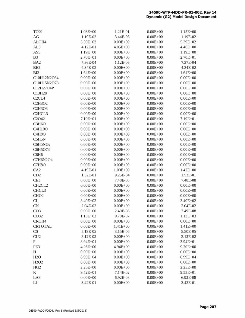
24590-WTP-MDD-PR-01-002, Rev 14 Dynamic (G2) Model Design Document
Page 207
24590-PADC-F00041 Rev 8 (Revised 3/5/2018)
TC99 1.03E+00 1.21E-01 0.00E+00 1.15E+00
AG 1.19E-02 3.44E-06 0.00E+00 1.19E-02
ALOH4 5.39E+02 0.00E+00 0.00E+00 5.39E+02
AL3 4.12E-01 4.05E+00 0.00E+00 4.46E+00
AS5 1.19E+00 0.00E+00 0.00E+00 1.19E+00
B3 2.70E+01 0.00E+00 0.00E+00 2.70E+01
BA2 7.36E-04 1.12E-06 0.00E+00 7.37E-04
BE2 4.34E-02 0.00E+00 0.00E+00 4.34E-02
BI3 1.64E+00 0.00E+00 0.00E+00 1.64E+00
C10H12N2O84 0.00E+00 0.00E+00 0.00E+00 0.00E+00
C10H15N2O73 0.00E+00 0.00E+00 0.00E+00 0.00E+00
C12H27O4P 0.00E+00 0.00E+00 0.00E+00 0.00E+00
C13H28 0.00E+00 0.00E+00 0.00E+00 0.00E+00
C2CL4 0.00E+00 0.00E+00 0.00E+00 0.00E+00
C2H3O2 0.00E+00 0.00E+00 0.00E+00 0.00E+00
C2H3O3 0.00E+00 0.00E+00 0.00E+00 0.00E+00
C2HCL3 0.00E+00 0.00E+00 0.00E+00 0.00E+00
C2O42 7.19E+01 0.00E+00 0.00E+00 7.19E+01
C3H6O 0.00E+00 0.00E+00 0.00E+00 0.00E+00
C4H10O 0.00E+00 0.00E+00 0.00E+00 0.00E+00
C4H8O 0.00E+00 0.00E+00 0.00E+00 0.00E+00
C5H5N 0.00E+00 0.00E+00 0.00E+00 0.00E+00
C6H5NO2 0.00E+00 0.00E+00 0.00E+00 0.00E+00
C6H5O73 0.00E+00 0.00E+00 0.00E+00 0.00E+00
C6H6 0.00E+00 0.00E+00 0.00E+00 0.00E+00
C7H6N2O4 0.00E+00 0.00E+00 0.00E+00 0.00E+00
C7H8O 0.00E+00 0.00E+00 0.00E+00 0.00E+00
CA2 4.19E-01 1.00E+00 0.00E+00 1.42E+00
CD2 1.52E-01 9.25E-04 0.00E+00 1.53E-01
CE3 0.00E+00 7.48E-08 0.00E+00 7.48E-08
CH2CL2 0.00E+00 0.00E+00 0.00E+00 0.00E+00
CHCL3 0.00E+00 0.00E+00 0.00E+00 0.00E+00
CHO2 0.00E+00 0.00E+00 0.00E+00 0.00E+00
CL 3.40E+02 0.00E+00 0.00E+00 3.40E+02
CN 2.04E-02 0.00E+00 0.00E+00 2.04E-02
CO3 0.00E+00 2.49E-08 0.00E+00 2.49E-08
CO32 1.13E+03 9.70E-07 0.00E+00 1.13E+03
CROH4 0.00E+00 0.00E+00 0.00E+00 0.00E+00
CRTOTAL 0.00E+00 1.41E+00 0.00E+00 1.41E+00
CS 5.19E-05 3.15E-06 0.00E+00 5.50E-05
CU2 3.12E-02 0.00E+00 0.00E+00 3.12E-02
F 3.94E+01 0.00E+00 0.00E+00 3.94E+01
FE3 4.26E+00 4.94E+00 0.00E+00 9.20E+00
H 0.00E+00 0.00E+00 0.00E+00 0.00E+00
H2O 8.99E+04 0.00E+00 0.00E+00 8.99E+04
H2O2 0.00E+00 0.00E+00 0.00E+00 0.00E+00
HG2 2.25E+00 0.00E+00 0.00E+00 2.25E+00
K 9.52E+01 7.14E-02 0.00E+00 9.53E+01
LA3 0.00E+00 6.92E-08 0.00E+00 6.92E-08
LI 3.42E-01 0.00E+00 0.00E+00 3.42E-01
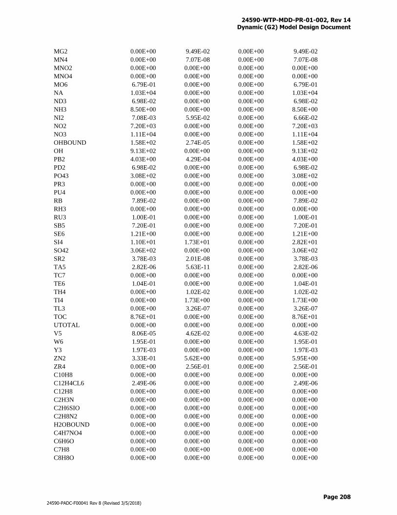
24590-WTP-MDD-PR-01-002, Rev 14 Dynamic (G2) Model Design Document
Page 208
24590-PADC-F00041 Rev 8 (Revised 3/5/2018)
MG2 0.00E+00 9.49E-02 0.00E+00 9.49E-02
MN4 0.00E+00 7.07E-08 0.00E+00 7.07E-08
MNO2 0.00E+00 0.00E+00 0.00E+00 0.00E+00
MNO4 0.00E+00 0.00E+00 0.00E+00 0.00E+00
MO6 6.79E-01 0.00E+00 0.00E+00 6.79E-01
NA 1.03E+04 0.00E+00 0.00E+00 1.03E+04
ND3 6.98E-02 0.00E+00 0.00E+00 6.98E-02
NH3 8.50E+00 0.00E+00 0.00E+00 8.50E+00
NI2 7.08E-03 5.95E-02 0.00E+00 6.66E-02
NO2 7.20E+03 0.00E+00 0.00E+00 7.20E+03
NO3 1.11E+04 0.00E+00 0.00E+00 1.11E+04
OHBOUND 1.58E+02 2.74E-05 0.00E+00 1.58E+02
OH 9.13E+02 0.00E+00 0.00E+00 9.13E+02
PB2 4.03E+00 4.29E-04 0.00E+00 4.03E+00
PD2 6.98E-02 0.00E+00 0.00E+00 6.98E-02
PO43 3.08E+02 0.00E+00 0.00E+00 3.08E+02
PR3 0.00E+00 0.00E+00 0.00E+00 0.00E+00
PU4 0.00E+00 0.00E+00 0.00E+00 0.00E+00
RB 7.89E-02 0.00E+00 0.00E+00 7.89E-02
RH3 0.00E+00 0.00E+00 0.00E+00 0.00E+00
RU3 1.00E-01 0.00E+00 0.00E+00 1.00E-01
SB5 7.20E-01 0.00E+00 0.00E+00 7.20E-01
SE6 1.21E+00 0.00E+00 0.00E+00 1.21E+00
SI4 1.10E+01 1.73E+01 0.00E+00 2.82E+01
SO42 3.06E+02 0.00E+00 0.00E+00 3.06E+02
SR2 3.78E-03 2.01E-08 0.00E+00 3.78E-03
TA5 2.82E-06 5.63E-11 0.00E+00 2.82E-06
TC7 0.00E+00 0.00E+00 0.00E+00 0.00E+00
TE6 1.04E-01 0.00E+00 0.00E+00 1.04E-01
TH4 0.00E+00 1.02E-02 0.00E+00 1.02E-02
TI4 0.00E+00 1.73E+00 0.00E+00 1.73E+00
TL3 0.00E+00 3.26E-07 0.00E+00 3.26E-07
TOC 8.76E+01 0.00E+00 0.00E+00 8.76E+01
UTOTAL 0.00E+00 0.00E+00 0.00E+00 0.00E+00
V5 8.06E-05 4.62E-02 0.00E+00 4.63E-02
W6 1.95E-01 0.00E+00 0.00E+00 1.95E-01
Y3 1.97E-03 0.00E+00 0.00E+00 1.97E-03
ZN2 3.33E-01 5.62E+00 0.00E+00 5.95E+00
ZR4 0.00E+00 2.56E-01 0.00E+00 2.56E-01
C10H8 0.00E+00 0.00E+00 0.00E+00 0.00E+00
C12H4CL6 2.49E-06 0.00E+00 0.00E+00 2.49E-06
C12H8 0.00E+00 0.00E+00 0.00E+00 0.00E+00
C2H3N 0.00E+00 0.00E+00 0.00E+00 0.00E+00
C2H6SIO 0.00E+00 0.00E+00 0.00E+00 0.00E+00
C2H8N2 0.00E+00 0.00E+00 0.00E+00 0.00E+00
H2OBOUND 0.00E+00 0.00E+00 0.00E+00 0.00E+00
C4H7NO4 0.00E+00 0.00E+00 0.00E+00 0.00E+00
C6H6O 0.00E+00 0.00E+00 0.00E+00 0.00E+00
C7H8 0.00E+00 0.00E+00 0.00E+00 0.00E+00
C8H8O 0.00E+00 0.00E+00 0.00E+00 0.00E+00
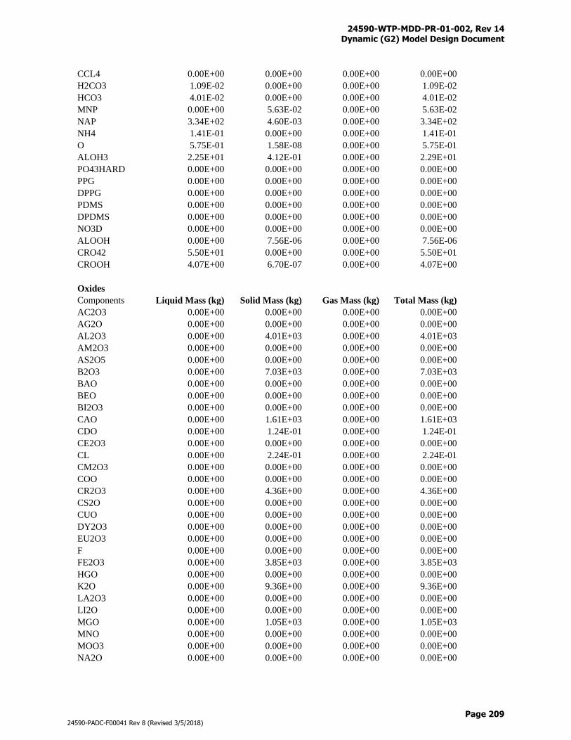
24590-WTP-MDD-PR-01-002, Rev 14 Dynamic (G2) Model Design Document
Page 209
24590-PADC-F00041 Rev 8 (Revised 3/5/2018)
CCL4 0.00E+00 0.00E+00 0.00E+00 0.00E+00
H2CO3 1.09E-02 0.00E+00 0.00E+00 1.09E-02
HCO3 4.01E-02 0.00E+00 0.00E+00 4.01E-02
MNP 0.00E+00 5.63E-02 0.00E+00 5.63E-02
NAP 3.34E+02 4.60E-03 0.00E+00 3.34E+02
NH4 1.41E-01 0.00E+00 0.00E+00 1.41E-01
O 5.75E-01 1.58E-08 0.00E+00 5.75E-01
ALOH3 2.25E+01 4.12E-01 0.00E+00 2.29E+01
PO43HARD 0.00E+00 0.00E+00 0.00E+00 0.00E+00
PPG 0.00E+00 0.00E+00 0.00E+00 0.00E+00
DPPG 0.00E+00 0.00E+00 0.00E+00 0.00E+00
PDMS 0.00E+00 0.00E+00 0.00E+00 0.00E+00
DPDMS 0.00E+00 0.00E+00 0.00E+00 0.00E+00
NO3D 0.00E+00 0.00E+00 0.00E+00 0.00E+00
ALOOH 0.00E+00 7.56E-06 0.00E+00 7.56E-06
CRO42 5.50E+01 0.00E+00 0.00E+00 5.50E+01
CROOH 4.07E+00 6.70E-07 0.00E+00 4.07E+00
Oxides
Components Liquid Mass (kg) Solid Mass (kg) Gas Mass (kg) Total Mass (kg)
AC2O3 0.00E+00 0.00E+00 0.00E+00 0.00E+00
AG2O 0.00E+00 0.00E+00 0.00E+00 0.00E+00
AL2O3 0.00E+00 4.01E+03 0.00E+00 4.01E+03
AM2O3 0.00E+00 0.00E+00 0.00E+00 0.00E+00
AS2O5 0.00E+00 0.00E+00 0.00E+00 0.00E+00
B2O3 0.00E+00 7.03E+03 0.00E+00 7.03E+03
BAO 0.00E+00 0.00E+00 0.00E+00 0.00E+00
BEO 0.00E+00 0.00E+00 0.00E+00 0.00E+00
BI2O3 0.00E+00 0.00E+00 0.00E+00 0.00E+00
CAO 0.00E+00 1.61E+03 0.00E+00 1.61E+03
CDO 0.00E+00 1.24E-01 0.00E+00 1.24E-01
CE2O3 0.00E+00 0.00E+00 0.00E+00 0.00E+00
CL 0.00E+00 2.24E-01 0.00E+00 2.24E-01
CM2O3 0.00E+00 0.00E+00 0.00E+00 0.00E+00
COO 0.00E+00 0.00E+00 0.00E+00 0.00E+00
CR2O3 0.00E+00 4.36E+00 0.00E+00 4.36E+00
CS2O 0.00E+00 0.00E+00 0.00E+00 0.00E+00
CUO 0.00E+00 0.00E+00 0.00E+00 0.00E+00
DY2O3 0.00E+00 0.00E+00 0.00E+00 0.00E+00
EU2O3 0.00E+00 0.00E+00 0.00E+00 0.00E+00
F 0.00E+00 0.00E+00 0.00E+00 0.00E+00
FE2O3 0.00E+00 3.85E+03 0.00E+00 3.85E+03
HGO 0.00E+00 0.00E+00 0.00E+00 0.00E+00
K2O 0.00E+00 9.36E+00 0.00E+00 9.36E+00
LA2O3 0.00E+00 0.00E+00 0.00E+00 0.00E+00
LI2O 0.00E+00 0.00E+00 0.00E+00 0.00E+00
MGO 0.00E+00 1.05E+03 0.00E+00 1.05E+03
MNO 0.00E+00 0.00E+00 0.00E+00 0.00E+00
MOO3 0.00E+00 0.00E+00 0.00E+00 0.00E+00
NA2O 0.00E+00 0.00E+00 0.00E+00 0.00E+00
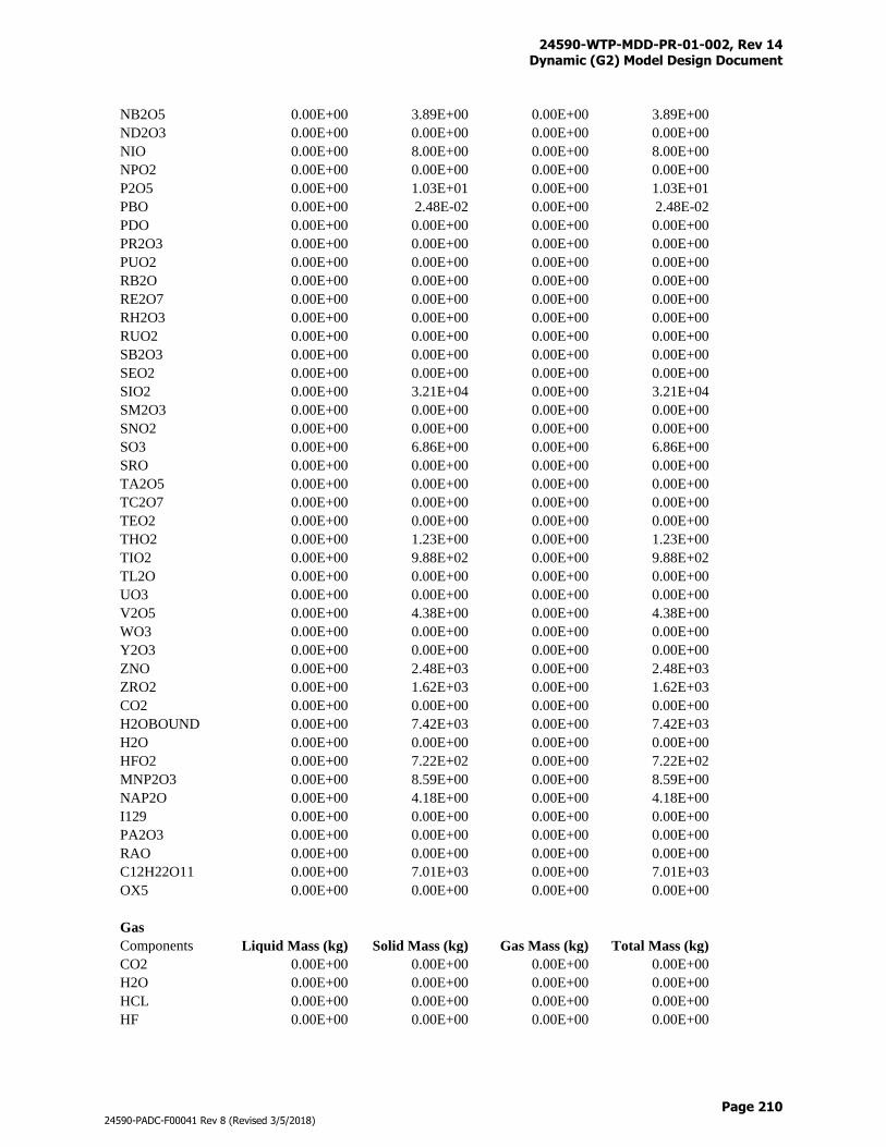
24590-WTP-MDD-PR-01-002, Rev 14 Dynamic (G2) Model Design Document
Page 210
24590-PADC-F00041 Rev 8 (Revised 3/5/2018)
NB2O5 0.00E+00 3.89E+00 0.00E+00 3.89E+00
ND2O3 0.00E+00 0.00E+00 0.00E+00 0.00E+00
NIO 0.00E+00 8.00E+00 0.00E+00 8.00E+00
NPO2 0.00E+00 0.00E+00 0.00E+00 0.00E+00
P2O5 0.00E+00 1.03E+01 0.00E+00 1.03E+01
PBO 0.00E+00 2.48E-02 0.00E+00 2.48E-02
PDO 0.00E+00 0.00E+00 0.00E+00 0.00E+00
PR2O3 0.00E+00 0.00E+00 0.00E+00 0.00E+00
PUO2 0.00E+00 0.00E+00 0.00E+00 0.00E+00
RB2O 0.00E+00 0.00E+00 0.00E+00 0.00E+00
RE2O7 0.00E+00 0.00E+00 0.00E+00 0.00E+00
RH2O3 0.00E+00 0.00E+00 0.00E+00 0.00E+00
RUO2 0.00E+00 0.00E+00 0.00E+00 0.00E+00
SB2O3 0.00E+00 0.00E+00 0.00E+00 0.00E+00
SEO2 0.00E+00 0.00E+00 0.00E+00 0.00E+00
SIO2 0.00E+00 3.21E+04 0.00E+00 3.21E+04
SM2O3 0.00E+00 0.00E+00 0.00E+00 0.00E+00
SNO2 0.00E+00 0.00E+00 0.00E+00 0.00E+00
SO3 0.00E+00 6.86E+00 0.00E+00 6.86E+00
SRO 0.00E+00 0.00E+00 0.00E+00 0.00E+00
TA2O5 0.00E+00 0.00E+00 0.00E+00 0.00E+00
TC2O7 0.00E+00 0.00E+00 0.00E+00 0.00E+00
TEO2 0.00E+00 0.00E+00 0.00E+00 0.00E+00
THO2 0.00E+00 1.23E+00 0.00E+00 1.23E+00
TIO2 0.00E+00 9.88E+02 0.00E+00 9.88E+02
TL2O 0.00E+00 0.00E+00 0.00E+00 0.00E+00
UO3 0.00E+00 0.00E+00 0.00E+00 0.00E+00
V2O5 0.00E+00 4.38E+00 0.00E+00 4.38E+00
WO3 0.00E+00 0.00E+00 0.00E+00 0.00E+00
Y2O3 0.00E+00 0.00E+00 0.00E+00 0.00E+00
ZNO 0.00E+00 2.48E+03 0.00E+00 2.48E+03
ZRO2 0.00E+00 1.62E+03 0.00E+00 1.62E+03
CO2 0.00E+00 0.00E+00 0.00E+00 0.00E+00
H2OBOUND 0.00E+00 7.42E+03 0.00E+00 7.42E+03
H2O 0.00E+00 0.00E+00 0.00E+00 0.00E+00
HFO2 0.00E+00 7.22E+02 0.00E+00 7.22E+02
MNP2O3 0.00E+00 8.59E+00 0.00E+00 8.59E+00
NAP2O 0.00E+00 4.18E+00 0.00E+00 4.18E+00
I129 0.00E+00 0.00E+00 0.00E+00 0.00E+00
PA2O3 0.00E+00 0.00E+00 0.00E+00 0.00E+00
RAO 0.00E+00 0.00E+00 0.00E+00 0.00E+00
C12H22O11 0.00E+00 7.01E+03 0.00E+00 7.01E+03
OX5 0.00E+00 0.00E+00 0.00E+00 0.00E+00
Gas
Components Liquid Mass (kg) Solid Mass (kg) Gas Mass (kg) Total Mass (kg)
CO2 0.00E+00 0.00E+00 0.00E+00 0.00E+00
H2O 0.00E+00 0.00E+00 0.00E+00 0.00E+00
HCL 0.00E+00 0.00E+00 0.00E+00 0.00E+00
HF 0.00E+00 0.00E+00 0.00E+00 0.00E+00
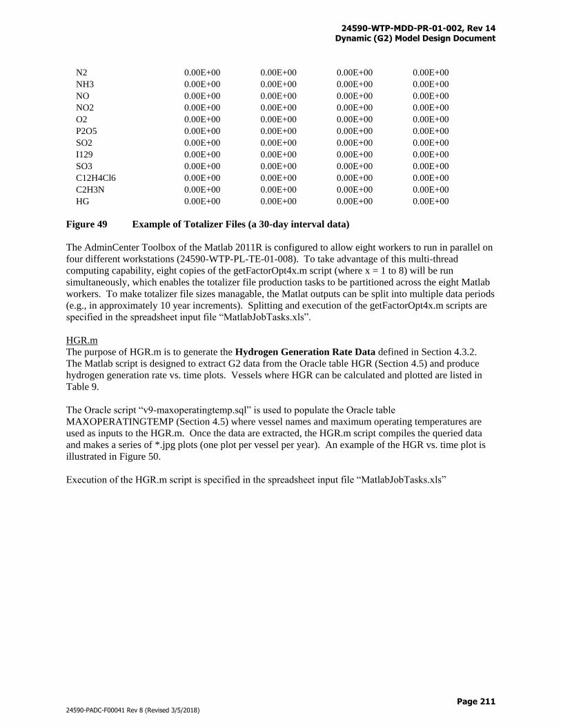
24590-WTP-MDD-PR-01-002, Rev 14 Dynamic (G2) Model Design Document
Page 211
24590-PADC-F00041 Rev 8 (Revised 3/5/2018)
N2 0.00E+00 0.00E+00 0.00E+00 0.00E+00
NH3 0.00E+00 0.00E+00 0.00E+00 0.00E+00
NO 0.00E+00 0.00E+00 0.00E+00 0.00E+00
NO2 0.00E+00 0.00E+00 0.00E+00 0.00E+00
O2 0.00E+00 0.00E+00 0.00E+00 0.00E+00
P2O5 0.00E+00 0.00E+00 0.00E+00 0.00E+00
SO2 0.00E+00 0.00E+00 0.00E+00 0.00E+00
I129 0.00E+00 0.00E+00 0.00E+00 0.00E+00
SO3 0.00E+00 0.00E+00 0.00E+00 0.00E+00
C12H4Cl6 0.00E+00 0.00E+00 0.00E+00 0.00E+00
C2H3N 0.00E+00 0.00E+00 0.00E+00 0.00E+00
HG 0.00E+00 0.00E+00 0.00E+00 0.00E+00
Figure 49 Example of Totalizer Files (a 30-day interval data)
The AdminCenter Toolbox of the Matlab 2011R is configured to allow eight workers to run in parallel on
four different workstations (24590-WTP-PL-TE-01-008). To take advantage of this multi-thread
computing capability, eight copies of the getFactorOpt4x.m script (where x = 1 to 8) will be run
simultaneously, which enables the totalizer file production tasks to be partitioned across the eight Matlab
workers. To make totalizer file sizes managable, the Matlat outputs can be split into multiple data periods
(e.g., in approximately 10 year increments). Splitting and execution of the getFactorOpt4x.m scripts are
specified in the spreadsheet input file “MatlabJobTasks.xls”.
HGR.m
The purpose of HGR.m is to generate the Hydrogen Generation Rate Data defined in Section 4.3.2.
The Matlab script is designed to extract G2 data from the Oracle table HGR (Section 4.5) and produce
hydrogen generation rate vs. time plots. Vessels where HGR can be calculated and plotted are listed in
Table 9.
The Oracle script “v9-maxoperatingtemp.sql” is used to populate the Oracle table
MAXOPERATINGTEMP (Section 4.5) where vessel names and maximum operating temperatures are
used as inputs to the HGR.m. Once the data are extracted, the HGR.m script compiles the queried data
and makes a series of *.jpg plots (one plot per vessel per year). An example of the HGR vs. time plot is
illustrated in Figure 50.
Execution of the HGR.m script is specified in the spreadsheet input file “MatlabJobTasks.xls”
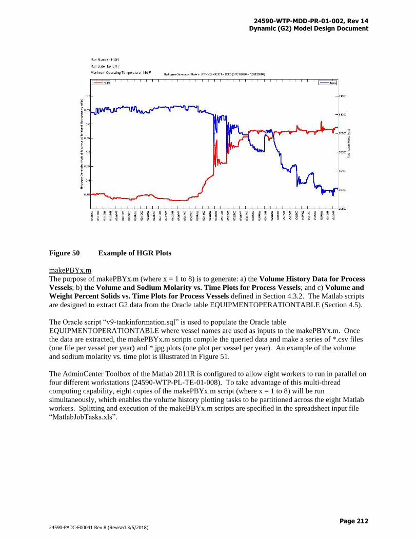
24590-WTP-MDD-PR-01-002, Rev 14 Dynamic (G2) Model Design Document
Page 212
24590-PADC-F00041 Rev 8 (Revised 3/5/2018)
Figure 50 Example of HGR Plots
makePBYx.m
The purpose of makePBYx.m (where x = 1 to 8) is to generate: a) the Volume History Data for Process
Vessels; b) the Volume and Sodium Molarity vs. Time Plots for Process Vessels; and c) Volume and
Weight Percent Solids vs. Time Plots for Process Vessels defined in Section 4.3.2. The Matlab scripts
are designed to extract G2 data from the Oracle table EQUIPMENTOPERATIONTABLE (Section 4.5).
The Oracle script “v9-tankinformation.sql” is used to populate the Oracle table
EQUIPMENTOPERATIONTABLE where vessel names are used as inputs to the makePBYx.m. Once
the data are extracted, the makePBYx.m scripts compile the queried data and make a series of *.csv files
(one file per vessel per year) and *.jpg plots (one plot per vessel per year). An example of the volume
and sodium molarity vs. time plot is illustrated in Figure 51.
The AdminCenter Toolbox of the Matlab 2011R is configured to allow eight workers to run in parallel on
four different workstations (24590-WTP-PL-TE-01-008). To take advantage of this multi-thread
computing capability, eight copies of the makePBYx.m script (where x = 1 to 8) will be run
simultaneously, which enables the volume history plotting tasks to be partitioned across the eight Matlab
workers. Splitting and execution of the makeBBYx.m scripts are specified in the spreadsheet input file
“MatlabJobTasks.xls”.
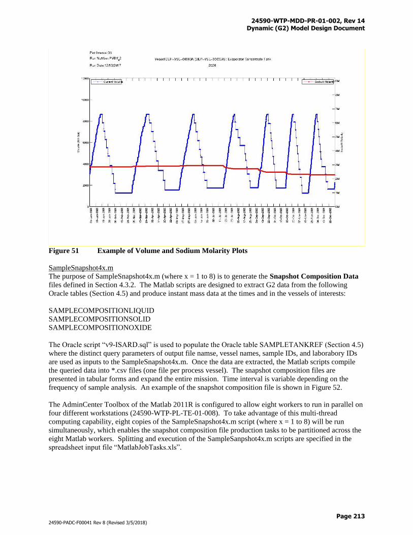
24590-WTP-MDD-PR-01-002, Rev 14 Dynamic (G2) Model Design Document
Page 213
24590-PADC-F00041 Rev 8 (Revised 3/5/2018)
Figure 51 Example of Volume and Sodium Molarity Plots
SampleSnapshot4x.m
The purpose of SampleSnapshot4x.m (where x = 1 to 8) is to generate the Snapshot Composition Data
files defined in Section 4.3.2. The Matlab scripts are designed to extract G2 data from the following
Oracle tables (Section 4.5) and produce instant mass data at the times and in the vessels of interests:
SAMPLECOMPOSITIONLIQUID
SAMPLECOMPOSITIONSOLID
SAMPLECOMPOSITIONOXIDE
The Oracle script “v9-ISARD.sql” is used to populate the Oracle table SAMPLETANKREF (Section 4.5)
where the distinct query parameters of output file namse, vessel names, sample IDs, and laborabory IDs
are used as inputs to the SampleSnapshot4x.m. Once the data are extracted, the Matlab scripts compile
the queried data into *.csv files (one file per process vessel). The snapshot composition files are
presented in tabular forms and expand the entire mission. Time interval is variable depending on the
frequency of sample analysis. An example of the snapshot composition file is shown in Figure 52.
The AdminCenter Toolbox of the Matlab 2011R is configured to allow eight workers to run in parallel on
four different workstations (24590-WTP-PL-TE-01-008). To take advantage of this multi-thread
computing capability, eight copies of the SampleSnapshot4x.m script (where x = 1 to 8) will be run
simultaneously, which enables the snapshot composition file production tasks to be partitioned across the
eight Matlab workers. Splitting and execution of the SampleSanpshot4x.m scripts are specified in the
spreadsheet input file “MatlabJobTasks.xls”.
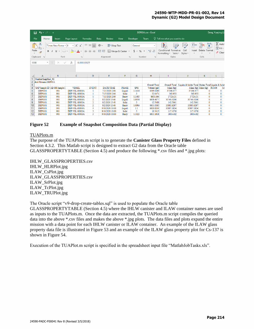
24590-WTP-MDD-PR-01-002, Rev 14 Dynamic (G2) Model Design Document
Page 214
24590-PADC-F00041 Rev 8 (Revised 3/5/2018)
Figure 52 Example of Snapshot Composition Data (Partial Display)
TUAPlots.m
The purpose of the TUAPlots.m script is to generate the Canister Glass Property Files defined in
Section 4.3.2. This Matlab script is designed to extract G2 data from the Oracle table
GLASSPROPERTYTABLE (Section 4.5) and produce the following *.csv files and *.jpg plots:
IHLW_GLASSPROPERTIES.csv
IHLW_HLRPlot.jpg
ILAW_CsPlot.jpg
ILAW_GLASSPROPERTIES.csv
ILAW_SrPlot.jpg
ILAW_TcPlot.jpg
ILAW_TRUPlot.jpg
The Oracle script “v9-drop-create-tables.sql” is used to populate the Oracle table
GLASSPROPERTYTABLE (Section 4.5) where the IHLW canister and ILAW container names are used
as inputs to the TUAPlots.m. Once the data are extracted, the TUAPlots.m script compiles the queried
data into the above *.csv files and makes the above *.jpg plots. The data files and plots expand the entire
mission with a data point for each IHLW canister or ILAW container. An example of the ILAW glass
property data file is illustrated in Figure 53 and an example of the ILAW glass property plot for Cs-137 is
shown in Figure 54.
Execution of the TUAPlot.m script is specified in the spreadsheet input file “MatlabJobTasks.xls”.

24590-WTP-MDD-PR-01-002, Rev 14 Dynamic (G2) Model Design Document
Page 215
24590-PADC-F00041 Rev 8 (Revised 3/5/2018)
Figure 53 Example of ILAW Glass Property Data (Partial Display)
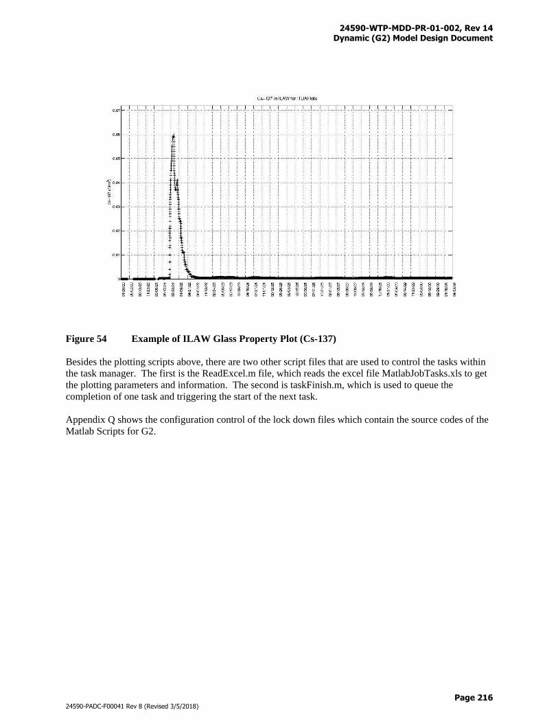
24590-WTP-MDD-PR-01-002, Rev 14 Dynamic (G2) Model Design Document
Page 216
24590-PADC-F00041 Rev 8 (Revised 3/5/2018)
Figure 54 Example of ILAW Glass Property Plot (Cs-137)
Besides the plotting scripts above, there are two other script files that are used to control the tasks within
the task manager. The first is the ReadExcel.m file, which reads the excel file MatlabJobTasks.xls to get
the plotting parameters and information. The second is taskFinish.m, which is used to queue the
completion of one task and triggering the start of the next task.
Appendix Q shows the configuration control of the lock down files which contain the source codes of the
Matlab Scripts for G2.
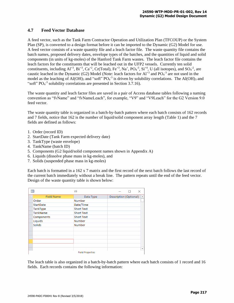
24590-WTP-MDD-PR-01-002, Rev 14 Dynamic (G2) Model Design Document
Page 217
24590-PADC-F00041 Rev 8 (Revised 3/5/2018)
4.7 Feed Vector Database
A feed vector, such as the Tank Farm Contractor Operation and Utilization Plan (TFCOUP) or the System
Plan (SP), is converted to a design format before it can be imported to the Dynamic (G2) Model for use.
A feed vector consists of a waste quantity file and a leach factor file. The waste quantity file contains the
batch names, proposed delivery dates, envelope types of the batches, and the quantities of liquid and solid
components (in units of kg-moles) of the Hanford Tank Farm wastes. The leach factor file contains the
leach factors for the constituents that will be leached out in the UFP2 vessels. Currently ten solid
constituents, including Al+3, Bi+3, Ca+2, Cr(Total), Fe+3, Na+, PO4-3, Si+4, U (all isotopes), and SO4
-2, are
caustic leached in the Dynamic (G2) Model (Note: leach factors for Al+3 and PO4-3 are not used in the
model as the leaching of Al(OH)3 and “soft” PO4-3 is driven by solubility correlations. The Al(OH)3 and
“soft” PO4-3 solubility correlations are presented in Section 3.7.16).
The waste quantity and leach factor files are saved in a pair of Access database tables following a naming
convention as “fvName” and “fvNameLeach”, for example, “V9” and “V9Leach” for the G2 Version 9.0
feed vector.
The waste quantity table is organized in a batch-by-batch pattern where each batch consists of 162 records
and 7 fields, notice that 162 is the number of liquid/solid component array length (Table 1) and the 7
fields are defined as follows:
1. Order (record ID)
2. StartDate (Tank Farm expected delivery date)
3. TankType (waste envelope)
4. TankName (batch ID)
5. Components (G2 liquid/solid component names shown in Appendix A)
6. Liquids (dissolve phase mass in kg-moles), and
7. Solids (suspended phase mass in kg-moles)
Each batch is formatted in a 162 x 7 matrix and the first record of the next batch follows the last record of
the current batch immediately without a break line. The pattern repeats until the end of the feed vector.
Design of the waste quantity table is shown below:
The leach table is also organized in a batch-by-batch pattern where each batch consists of 1 record and 16
fields. Each records contains the following information:
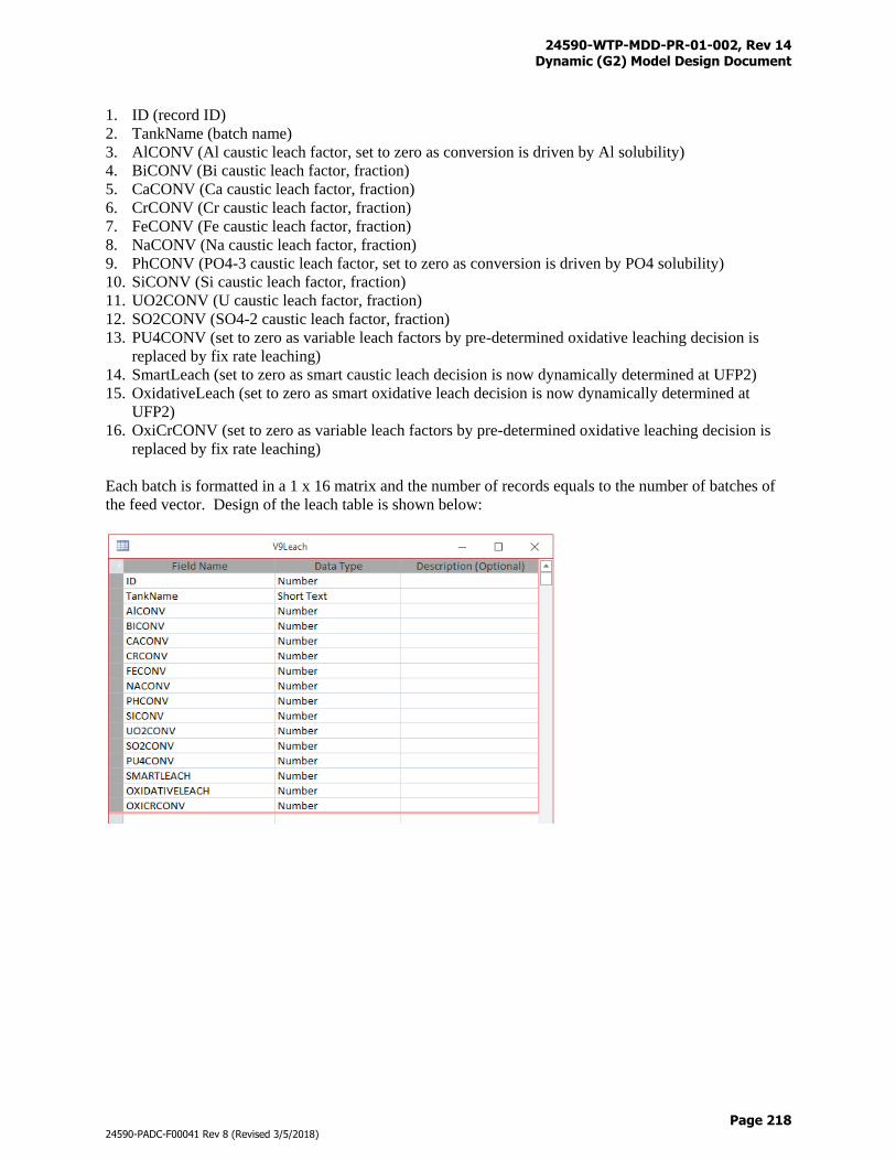
24590-WTP-MDD-PR-01-002, Rev 14 Dynamic (G2) Model Design Document
Page 218
24590-PADC-F00041 Rev 8 (Revised 3/5/2018)
1. ID (record ID)
2. TankName (batch name)
3. AlCONV (Al caustic leach factor, set to zero as conversion is driven by Al solubility)
4. BiCONV (Bi caustic leach factor, fraction)
5. CaCONV (Ca caustic leach factor, fraction)
6. CrCONV (Cr caustic leach factor, fraction)
7. FeCONV (Fe caustic leach factor, fraction)
8. NaCONV (Na caustic leach factor, fraction)
9. PhCONV (PO4-3 caustic leach factor, set to zero as conversion is driven by PO4 solubility)
10. SiCONV (Si caustic leach factor, fraction)
11. UO2CONV (U caustic leach factor, fraction)
12. SO2CONV (SO4-2 caustic leach factor, fraction)
13. PU4CONV (set to zero as variable leach factors by pre-determined oxidative leaching decision is
replaced by fix rate leaching)
14. SmartLeach (set to zero as smart caustic leach decision is now dynamically determined at UFP2)
15. OxidativeLeach (set to zero as smart oxidative leach decision is now dynamically determined at
UFP2)
16. OxiCrCONV (set to zero as variable leach factors by pre-determined oxidative leaching decision is
replaced by fix rate leaching)
Each batch is formatted in a 1 x 16 matrix and the number of records equals to the number of batches of
the feed vector. Design of the leach table is shown below:
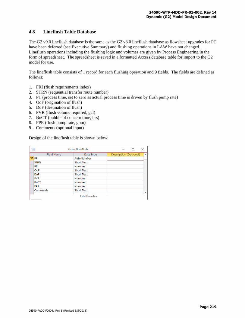
24590-WTP-MDD-PR-01-002, Rev 14 Dynamic (G2) Model Design Document
Page 219
24590-PADC-F00041 Rev 8 (Revised 3/5/2018)
4.8 Lineflush Table Database
The G2 v9.0 lineflush database is the same as the G2 v8.0 lineflush database as flowsheet upgrades for PT
have been deferred (see Executive Summary) and flushing operations in LAW have not changed.
Lineflush operations including the flushing logic and volumes are given by Process Engineering in the
form of spreadsheet. The spreadsheet is saved in a formatted Access database table for import to the G2
model for use.
The lineflush table consists of 1 record for each flushing operation and 9 fields. The fields are defined as
follows:
1. FRI (flush requirements index)
2. STRN (sequential transfer route number)
3. PT (process time, set to zero as actual process time is driven by flush pump rate)
4. OoF (origination of flush)
5. DoF (destination of flush)
6. FVR (flush volume required, gal)
7. BoCT (bubble of concern time, hrs)
8. FPR (flush pump rate, gpm)
9. Comments (optional input)
Design of the lineflush table is shown below:
24590-WTP-MDD-PR-01-002, Rev 14 Dynamic (G2) Model Design Document
Page 220
24590-PADC-F00041 Rev 8 (Revised 3/5/2018)
5 Reference
Project Documents
24590-PTF-ES-ENG-14-001, Rev 0, Standardized High Solids Vessel Design (SHSVD) Recommendation
24590-PTF-ES-ENG-17-001, Rev 0, PT Facility Standard High-Solids Vessel Concept Design
Alternative Study
24590-WTP-GPG-PENG-0005, Rev 3, Run Requests and Change Requests for Process Models
24590-WTP-GPG-PENG-00006, Rev 2, Naming Conventions for Version Control of Level E Process
Models
24590-WTP-GPP-RAEN-EN-0028, Rev 0, Life Cycle Control of “Level E” Process Model
24590-WTP-M4C-V37T-00009, Rev 0, Phosphate Solubility Algorithm
24590-WTP-MCR-PE-13-0023, Rev 0, Variable HLW Melt Rate
24590-WTP-MCR-PE-13-0024, Rev 0, Variable LAW Melt Rate
24590-WTP-MCR-PE-13-0030, Rev 0, Application of Cesium Ion Exchange Elution Curves
24590-WTP-MCR-PET-09-0048, Rev 1, Caustic Leaching Requirements and Optimum Aluminum
Leaching Routine to Use with HLW Glass Shell V2.0
24590-WTP-MCR-PET-09-0049, Rev 1, Oxidative Leaching Smart Logic to Use with HLW Glass Shell
V2.0
24590-WTP-MCR-PENG-17-0001, Rev 0, LAW Melter Downtime Effects
24590-WTP-MCR-PENG-17-0014, Rev 1, DFLAW Addition to G2 Flowsheet
24590-WTP-MCR-PENG-17-0015, Rev 1, Startup Commissioning of the DFLAW for G2
24590-WTP-MCR-PENG-17-0016, Rev 0, Oracle and Matlab Scripts for G2 Version 9.0
24590-WTP-MRQ-PENG-16-0008, Rev 0, Sensitivity Study for Melter Idling Impacts
24590-WTP-MRQ-PENG-16-0012, Rev 0, Evaluate LAW Melter Candidate Start-up Frits, Simulant, and
Spikes
24590-WTP-MRR-PENG-17-001, Rev 0, SHSV Concept Design – G2 Flowsheet Run Results
24590-WTP-PL-PR-04-0001, Rev 3, Integrated Sampling and Analysis Requirements Document (ISARD)
24590-WTP-PL-TE-01-008, Rev 21, System Design for Process Modeling
24590-WTP-PSRA-PENG-15-0010, Rev 2, Dynamic (G2) Flowsheet
24590-WTP-MDD-PR-01-002, Rev 14 Dynamic (G2) Model Design Document
Page 221
24590-PADC-F00041 Rev 8 (Revised 3/5/2018)
24590-WTP-RPT-ENG-01-001, Rev 11, Technical Baseline Description
24590-WTP-RPT-PE-14-001, Rev 0, Functional Specification and Utilization Evaluation of Select WTP
Vessels to Support Development of an Optimal Vessel Design Concept
24590-WTP-RPT-PE-13-003, Rev 0, 2013 Tank Utilization Assessment (TUA) Part 1: Potential Impact
of Advanced Glass Models on the WTP
24590-WTP-RPT-PR-01-011, Rev 0, Mercury Pathway and Treatment Assessment for the WTP
24590-WTP-RPT-PT-02-005, Rev 8, Flowsheet Bases, Assumptions, and Requirements
24590-WTP-SWLCD-PENG-17-0031, Rev 1, Dynamic (G2) Flowsheet Version 9.0 Software Life Cycle
Document
CCN 160514, Gibbsite Solubility Models, Supersedes CCN 137192.
CCN 160518, Sodium Oxalate Solubility Model for the Dynamic Flowsheet Rev 1. Supersedes CCN
15320.
CCN 221451, Conversion of CCN 150372 Aluminum Solubility Equations (3) to a Reversible Form
CCN 259607, Dynamic (G2) Flowsheet Version 8.0
CCN 303984, Dynamic (G2) Flowsheet Version 9.0 Verification and Validation Package
CCN 303985, Dynamic (G2) Flowsheet Version 9.0 Release for Use
Other Documents
DOE 2000, Contract No. DE-AC27-01RV14136, US Department of Energy, Richland, WA, as amended.
DOE 2013, Hanford Tank Waste Retrieval, Treatment, and Disposition Framework, Washington, D.C.
DOE 2017, Contract No. DE-AC27-01RV14136, Required Work to Resolve Technical Issues and Support
Conditional Release of Production Engineering, Procurement and Construction for the Pretreatment
Facility, 17-WTP-0014, Richland, WA
RPP-40149-Vol2, Rev 3, Integrated Waste Feed Delivery Plan Volume 2 – Campaign Sequence
RPP-RPT-58985, Rev 01A, Direct-Feed Low-Activity Waste: First Feed Flowsheet
Vienna, J.D. et al, Glass Property Models and Constraints for Estimating the Glass to Be Produced at
Hanford by Implementing Current Advanced Glass Formulation Efforts, Draft, July 2013
WRPS-54224-VA, Technetium Retention During LAW Vitrification with Recycle Flow-Sheet as
Presented by ES/VSL, Slide 13, Vitreous State Laboratory (VSL), The Cathodic University of America,
Washington, D.C. 2013

24590-WTP-MDD-PR-01-002, Rev 14 Dynamic (G2) Model Design Document
Page A-i
24590-PADC-F00041 Rev 8 (Revised 3/5/2018)
Appendix A
Component List
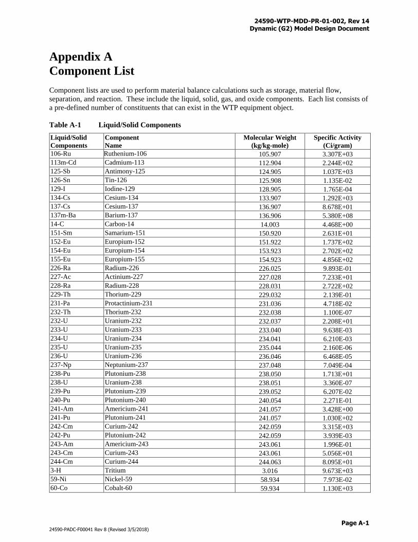
24590-WTP-MDD-PR-01-002, Rev 14 Dynamic (G2) Model Design Document
Page A-1
24590-PADC-F00041 Rev 8 (Revised 3/5/2018)
Appendix A
Component List
Component lists are used to perform material balance calculations such as storage, material flow,
separation, and reaction. These include the liquid, solid, gas, and oxide components. Each list consists of
a pre-defined number of constituents that can exist in the WTP equipment object.
Table A-1 Liquid/Solid Components
Liquid/Solid
Components
Component
Name
Molecular Weight
(kg/kg-mole)
Specific Activity
(Ci/gram)
106-Ru Ruthenium-106 105.907 3.307E+03
113m-Cd Cadmium-113 112.904 2.244E+02
125-Sb Antimony-125 124.905 1.037E+03
126-Sn Tin-126 125.908 1.135E-02
129-I Iodine-129 128.905 1.765E-04
134-Cs Cesium-134 133.907 1.292E+03
137-Cs Cesium-137 136.907 8.678E+01
137m-Ba Barium-137 136.906 5.380E+08
14-C Carbon-14 14.003 4.468E+00
151-Sm Samarium-151 150.920 2.631E+01
152-Eu Europium-152 151.922 1.737E+02
154-Eu Europium-154 153.923 2.702E+02
155-Eu Europium-155 154.923 4.856E+02
226-Ra Radium-226 226.025 9.893E-01
227-Ac Actinium-227 227.028 7.233E+01
228-Ra Radium-228 228.031 2.722E+02
229-Th Thorium-229 229.032 2.139E-01
231-Pa Protactinium-231 231.036 4.718E-02
232-Th Thorium-232 232.038 1.100E-07
232-U Uranium-232 232.037 2.208E+01
233-U Uranium-233 233.040 9.638E-03
234-U Uranium-234 234.041 6.210E-03
235-U Uranium-235 235.044 2.160E-06
236-U Uranium-236 236.046 6.468E-05
237-Np Neptunium-237 237.048 7.049E-04
238-Pu Plutonium-238 238.050 1.713E+01
238-U Uranium-238 238.051 3.360E-07
239-Pu Plutonium-239 239.052 6.207E-02
240-Pu Plutonium-240 240.054 2.271E-01
241-Am Americium-241 241.057 3.428E+00
241-Pu Plutonium-241 241.057 1.030E+02
242-Cm Curium-242 242.059 3.315E+03
242-Pu Plutonium-242 242.059 3.939E-03
243-Am Americium-243 243.061 1.996E-01
243-Cm Curium-243 243.061 5.056E+01
244-Cm Curium-244 244.063 8.095E+01
3-H Tritium 3.016 9.673E+03
59-Ni Nickel-59 58.934 7.973E-02
60-Co Cobalt-60 59.934 1.130E+03
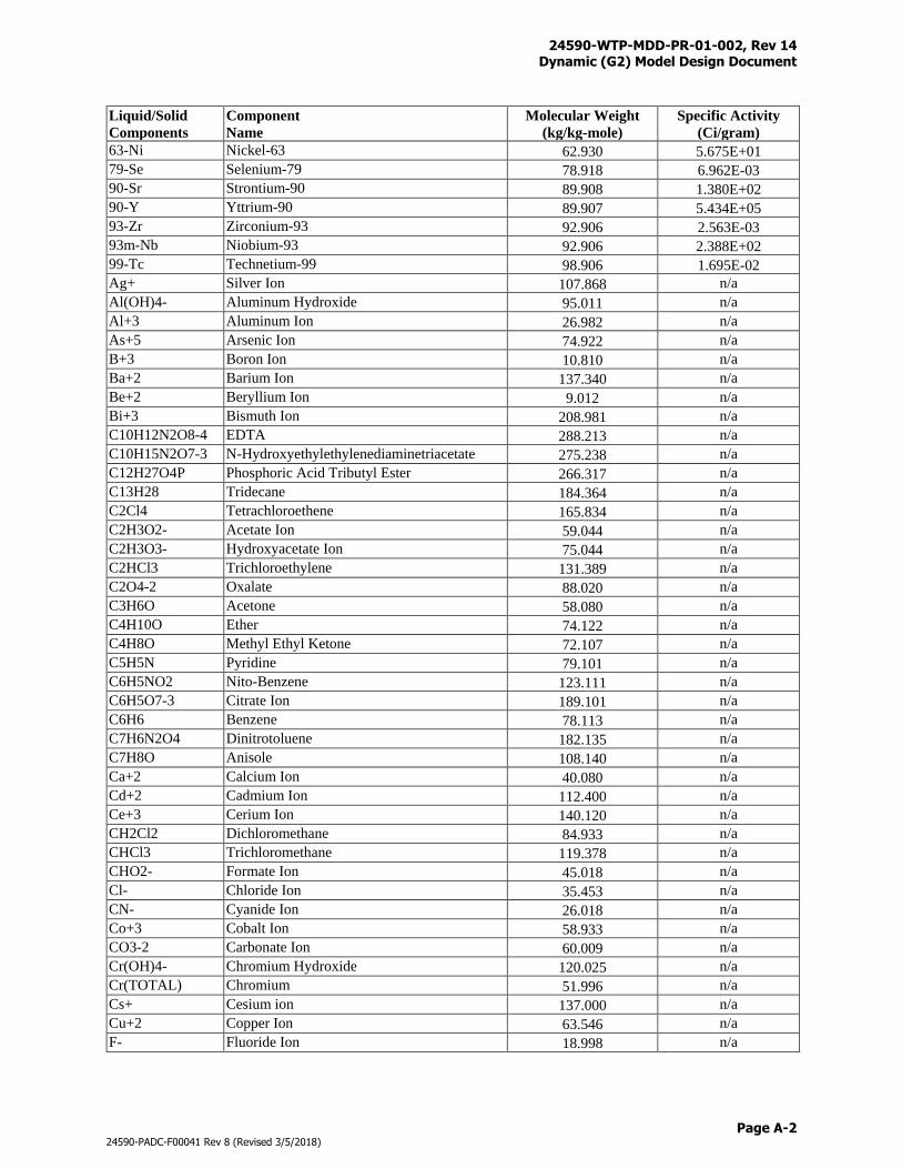
24590-WTP-MDD-PR-01-002, Rev 14 Dynamic (G2) Model Design Document
Page A-2
24590-PADC-F00041 Rev 8 (Revised 3/5/2018)
Liquid/Solid
Components
Component
Name
Molecular Weight
(kg/kg-mole)
Specific Activity
(Ci/gram)
63-Ni Nickel-63 62.930 5.675E+01
79-Se Selenium-79 78.918 6.962E-03
90-Sr Strontium-90 89.908 1.380E+02
90-Y Yttrium-90 89.907 5.434E+05
93-Zr Zirconium-93 92.906 2.563E-03
93m-Nb Niobium-93 92.906 2.388E+02
99-Tc Technetium-99 98.906 1.695E-02
Ag+ Silver Ion 107.868 n/a
Al(OH)4- Aluminum Hydroxide 95.011 n/a
Al+3 Aluminum Ion 26.982 n/a
As+5 Arsenic Ion 74.922 n/a
B+3 Boron Ion 10.810 n/a
Ba+2 Barium Ion 137.340 n/a
Be+2 Beryllium Ion 9.012 n/a
Bi+3 Bismuth Ion 208.981 n/a
C10H12N2O8-4 EDTA 288.213 n/a
C10H15N2O7-3 N-Hydroxyethylethylenediaminetriacetate 275.238 n/a
C12H27O4P Phosphoric Acid Tributyl Ester 266.317 n/a
C13H28 Tridecane 184.364 n/a
C2Cl4 Tetrachloroethene 165.834 n/a
C2H3O2- Acetate Ion 59.044 n/a
C2H3O3- Hydroxyacetate Ion 75.044 n/a
C2HCl3 Trichloroethylene 131.389 n/a
C2O4-2 Oxalate 88.020 n/a
C3H6O Acetone 58.080 n/a
C4H10O Ether 74.122 n/a
C4H8O Methyl Ethyl Ketone 72.107 n/a
C5H5N Pyridine 79.101 n/a
C6H5NO2 Nito-Benzene 123.111 n/a
C6H5O7-3 Citrate Ion 189.101 n/a
C6H6 Benzene 78.113 n/a
C7H6N2O4 Dinitrotoluene 182.135 n/a
C7H8O Anisole 108.140 n/a
Ca+2 Calcium Ion 40.080 n/a
Cd+2 Cadmium Ion 112.400 n/a
Ce+3 Cerium Ion 140.120 n/a
CH2Cl2 Dichloromethane 84.933 n/a
CHCl3 Trichloromethane 119.378 n/a
CHO2- Formate Ion 45.018 n/a
Cl- Chloride Ion 35.453 n/a
CN- Cyanide Ion 26.018 n/a
Co+3 Cobalt Ion 58.933 n/a
CO3-2 Carbonate Ion 60.009 n/a
Cr(OH)4- Chromium Hydroxide 120.025 n/a
Cr(TOTAL) Chromium 51.996 n/a
Cs+ Cesium ion 137.000 n/a
Cu+2 Copper Ion 63.546 n/a
F- Fluoride Ion 18.998 n/a
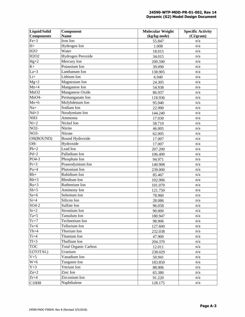
24590-WTP-MDD-PR-01-002, Rev 14 Dynamic (G2) Model Design Document
Page A-3
24590-PADC-F00041 Rev 8 (Revised 3/5/2018)
Liquid/Solid
Components
Component
Name
Molecular Weight
(kg/kg-mole)
Specific Activity
(Ci/gram)
Fe+3 Iron Ion 55.847 n/a
H+ Hydrogen Ion 1.008 n/a
H2O Water 18.015 n/a
H2O2 Hydrogen Peroxide 34.015 n/a
Hg+2 Mercury Ion 200.590 n/a
K+ Potassium Ion 39.090 n/a
La+3 Lanthanum Ion 138.905 n/a
Li+ Lithium Ion 6.940 n/a
Mg+2 Magnesium Ion 24.305 n/a
Mn+4 Manganese Ion 54.938 n/a
MnO2 Manganese Oxide 86.937 n/a
MnO4- Permanganate Ion 118.936 n/a
Mo+6 Molybdenum Ion 95.940 n/a
Na+ Sodium Ion 22.990 n/a
Nd+3 Neodymium Ion 144.240 n/a
NH3 Ammonia 17.030 n/a
Ni+2 Nickel Ion 58.710 n/a
NO2- Nitrite 46.005 n/a
NO3- Nitrate 62.005 n/a
OH(BOUND) Bound Hydroxide 17.007 n/a
OH- Hydroxide 17.007 n/a
Pb+2 Lead Ion 207.200 n/a
Pd+2 Palladium Ion 106.400 n/a
PO4-3 Phosphate Ion 94.971 n/a
Pr+3 Praseodymium Ion 140.908 n/a
Pu+4 Plutonium Ion 239.000 n/a
Rb+ Rubidium Ion 85.467 n/a
Rh+3 Rhodium Ion 102.906 n/a
Ru+3 Ruthenium Ion 101.070 n/a
Sb+5 Antimony Ion 121.750 n/a
Se+6 Selenium Ion 78.960 n/a
Si+4 Silicon Ion 28.086 n/a
SO4-2 Sulfate Ion 96.058 n/a
Sr+2 Strontium Ion 90.000 n/a
Ta+5 Tantalum Ion 180.947 n/a
Tc+7 Technetium Ion 98.906 n/a
Te+6 Tellurium Ion 127.600 n/a
Th+4 Thorium Ion 232.038 n/a
Ti+4 Titanium Ion 47.900 n/a
Tl+3 Thallium Ion 204.370 n/a
TOC Total Organic Carbon 12.011 n/a
U(TOTAL) Uranium 238.029 n/a
V+5 Vanadium Ion 50.941 n/a
W+6 Tungsten Ion 183.850 n/a
Y+3 Yttrium Ion 88.906 n/a
Zn+2 Zinc Ion 65.380 n/a
Zr+4 Zirconium Ion 91.220 n/a
C10H8 Naphthalene 128.175 n/a
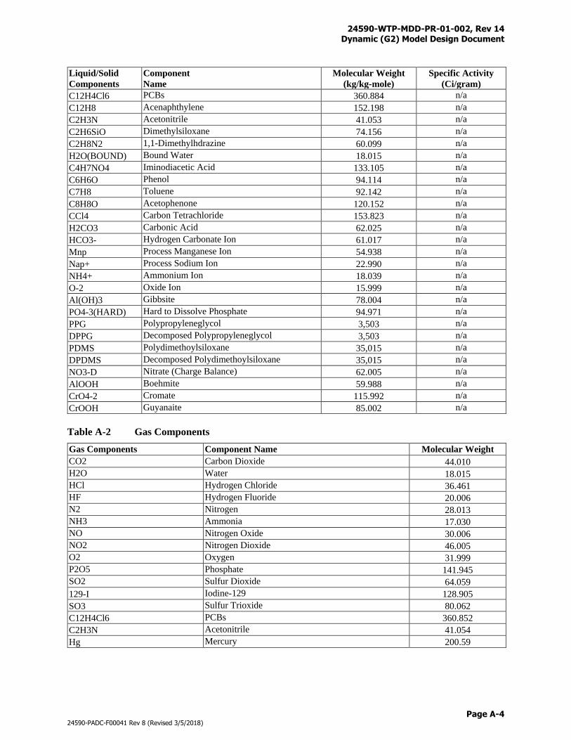
24590-WTP-MDD-PR-01-002, Rev 14 Dynamic (G2) Model Design Document
Page A-4
24590-PADC-F00041 Rev 8 (Revised 3/5/2018)
Liquid/Solid
Components
Component
Name
Molecular Weight
(kg/kg-mole)
Specific Activity
(Ci/gram)
C12H4Cl6 PCBs 360.884 n/a
C12H8 Acenaphthylene 152.198 n/a
C2H3N Acetonitrile 41.053 n/a
C2H6SiO Dimethylsiloxane 74.156 n/a
C2H8N2 1,1-Dimethylhdrazine 60.099 n/a
H2O(BOUND) Bound Water 18.015 n/a
C4H7NO4 Iminodiacetic Acid 133.105 n/a
C6H6O Phenol 94.114 n/a
C7H8 Toluene 92.142 n/a
C8H8O Acetophenone 120.152 n/a
CCl4 Carbon Tetrachloride 153.823 n/a
H2CO3 Carbonic Acid 62.025 n/a
HCO3- Hydrogen Carbonate Ion 61.017 n/a
Mnp Process Manganese Ion 54.938 n/a
Nap+ Process Sodium Ion 22.990 n/a
NH4+ Ammonium Ion 18.039 n/a
O-2 Oxide Ion 15.999 n/a
Al(OH)3 Gibbsite 78.004 n/a
PO4-3(HARD) Hard to Dissolve Phosphate 94.971 n/a
PPG Polypropyleneglycol 3,503 n/a
DPPG Decomposed Polypropyleneglycol 3,503 n/a
PDMS Polydimethoylsiloxane 35,015 n/a
DPDMS Decomposed Polydimethoylsiloxane 35,015 n/a
NO3-D Nitrate (Charge Balance) 62.005 n/a
AlOOH Boehmite 59.988 n/a
CrO4-2 Cromate 115.992 n/a
CrOOH Guyanaite 85.002 n/a
Table A-2 Gas Components
Gas Components Component Name Molecular Weight
CO2 Carbon Dioxide 44.010
H2O Water 18.015
HCl Hydrogen Chloride 36.461
HF Hydrogen Fluoride 20.006
N2 Nitrogen 28.013
NH3 Ammonia 17.030
NO Nitrogen Oxide 30.006
NO2 Nitrogen Dioxide 46.005
O2 Oxygen 31.999
P2O5 Phosphate 141.945
SO2 Sulfur Dioxide 64.059
129-I Iodine-129 128.905
SO3 Sulfur Trioxide 80.062
C12H4Cl6 PCBs 360.852
C2H3N Acetonitrile 41.054
Hg Mercury 200.59
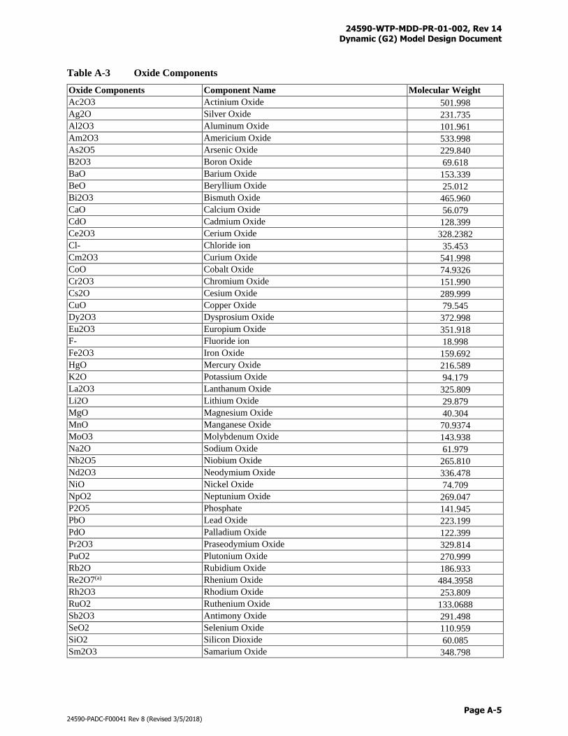
24590-WTP-MDD-PR-01-002, Rev 14 Dynamic (G2) Model Design Document
Page A-5
24590-PADC-F00041 Rev 8 (Revised 3/5/2018)
Table A-3 Oxide Components
Oxide Components Component Name Molecular Weight
Ac2O3 Actinium Oxide 501.998
Ag2O Silver Oxide 231.735
Al2O3 Aluminum Oxide 101.961
Am2O3 Americium Oxide 533.998
As2O5 Arsenic Oxide 229.840
B2O3 Boron Oxide 69.618
BaO Barium Oxide 153.339
BeO Beryllium Oxide 25.012
Bi2O3 Bismuth Oxide 465.960
CaO Calcium Oxide 56.079
CdO Cadmium Oxide 128.399
Ce2O3 Cerium Oxide 328.2382
Cl- Chloride ion 35.453
Cm2O3 Curium Oxide 541.998
CoO Cobalt Oxide 74.9326
Cr2O3 Chromium Oxide 151.990
Cs2O Cesium Oxide 289.999
CuO Copper Oxide 79.545
Dy2O3 Dysprosium Oxide 372.998
Eu2O3 Europium Oxide 351.918
F- Fluoride ion 18.998
Fe2O3 Iron Oxide 159.692
HgO Mercury Oxide 216.589
K2O Potassium Oxide 94.179
La2O3 Lanthanum Oxide 325.809
Li2O Lithium Oxide 29.879
MgO Magnesium Oxide 40.304
MnO Manganese Oxide 70.9374
MoO3 Molybdenum Oxide 143.938
Na2O Sodium Oxide 61.979
Nb2O5 Niobium Oxide 265.810
Nd2O3 Neodymium Oxide 336.478
NiO Nickel Oxide 74.709
NpO2 Neptunium Oxide 269.047
P2O5 Phosphate 141.945
PbO Lead Oxide 223.199
PdO Palladium Oxide 122.399
Pr2O3 Praseodymium Oxide 329.814
PuO2 Plutonium Oxide 270.999
Rb2O Rubidium Oxide 186.933
Re2O7(a) Rhenium Oxide 484.3958
Rh2O3 Rhodium Oxide 253.809
RuO2 Ruthenium Oxide 133.0688
Sb2O3 Antimony Oxide 291.498
SeO2 Selenium Oxide 110.959
SiO2 Silicon Dioxide 60.085
Sm2O3 Samarium Oxide 348.798
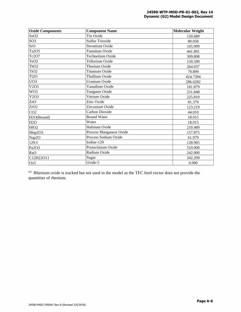
24590-WTP-MDD-PR-01-002, Rev 14 Dynamic (G2) Model Design Document
Page A-6
24590-PADC-F00041 Rev 8 (Revised 3/5/2018)
Oxide Components Component Name Molecular Weight
SnO2 Tin Oxide 150.689
SO3 Sulfur Trioxide 80.058
SrO Strontium Oxide 105.999
Ta2O5 Tantalum Oxide 441.891
Tc2O7 Technetium Oxide 309.808
TeO2 Tellurium Oxide 159.599
ThO2 Thorium Oxide 264.037
TiO2 Titanium Oxide 79.899
Tl2O Thallium Oxide 424.7394
UO3 Uranium Oxide 286.0282
V2O5 Vanadium Oxide 181.879
WO3 Tungsten Oxide 231.848
Y2O3 Yttrium Oxide 225.810
ZnO Zinc Oxide 81.379
ZrO2 Zirconium Oxide 123.219
CO2 Carbon Dioxide 44.010
H2O(Bound) Bound Water 18.015
H2O Water 18.015
HfO2 Hafnium Oxide 210.489
Mnp2O3 Process Manganese Oxide 157.875
Nap2O Process Sodium Oxide 61.979
129-I Iodine-129 128.905
Pa2O3 Protactinium Oxide 510.000
RaO Radium Oxide 242.000
C12H22O11 Sugar 342.299
Ox5 Oxide-5 0.000
(a) Rhenium oxide is tracked but not used in the model as the TFC feed vector does not provide the
quantities of rhenium.
24590-WTP-MDD-PR-01-002, Rev 14 Dynamic (G2) Model Design Document
Page B-i
24590-PADC-F00041 Rev 8 (Revised 3/5/2018)
Appendix B
Chemical Adds
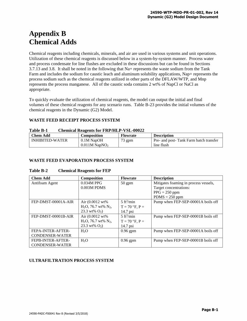
24590-WTP-MDD-PR-01-002, Rev 14 Dynamic (G2) Model Design Document
Page B-1
24590-PADC-F00041 Rev 8 (Revised 3/5/2018)
Appendix B
Chemical Adds
Chemical reagents including chemicals, minerals, and air are used in various systems and unit operations.
Utilization of these chemical reagents is discussed below in a system-by-system manner. Process water
and process condensate for line flushes are excluded in these discussions but can be found in Sections
3.7.13 and 3.8. It shall be noted in the following that Na+ represents the waste sodium from the Tank
Farm and includes the sodium for caustic leach and aluminum solubility applications, Nap+ represents the
process sodium such as the chemical reagents utilized in other parts of the DFLAW/WTP, and Mnp
represents the process manganese. All of the caustic soda contains 2 wt% of NapCl or NaCl as
appropriate.
To quickly evaluate the utilization of chemical reagents, the model can output the initial and final
volumes of these chemical reagents for any scenario runs. Table B-23 provides the initial volumes of the
chemical reagents in the Dynamic (G2) Model.
WASTE FEED RECEIPT PROCESS SYSTEM
Table B-1 Chemical Reagents for FRP/HLP-VSL-00022 Chem Add Composition Flowrate Description
INHIBITED-WATER 0.1M NapOH
0.011M NapNO2
73 gpm Pre- and post- Tank Farm batch transfer
line flush
WASTE FEED EVAPORATION PROCESS SYSTEM
Table B-2 Chemical Reagents for FEP
Chem Add Composition Flowrate Description
Antifoam Agent 0.034M PPG
0.003M PDMS
50 gpm Mitigates foaming in process vessels,
Target concentrations:
PPG = 250 ppm
PDMS = 250 ppm
FEP-DMST-00001A-AIR Air (0.0012 wt%
H2O, 76.7 wt% N2,
23.3 wt% O2)
5 ft3/min
T = 70 F, P =
14.7 psi
Pump when FEP-SEP-00001A boils off
FEP-DMST-00001B-AIR Air (0.0012 wt%
H2O, 76.7 wt% N2,
23.3 wt% O2)
5 ft3/min
T = 70 F, P =
14.7 psi
Pump when FEP-SEP-00001B boils off
FEPA-INTER-AFTER-
CONDENSER-WATER
H2O 0.96 gpm Pump when FEP-SEP-00001A boils off
FEPB-INTER-AFTER-
CONDENSER-WATER
H2O 0.96 gpm Pump when FEP-SEP-00001B boils off
ULTRAFILTRATION PROCESS SYSTEM
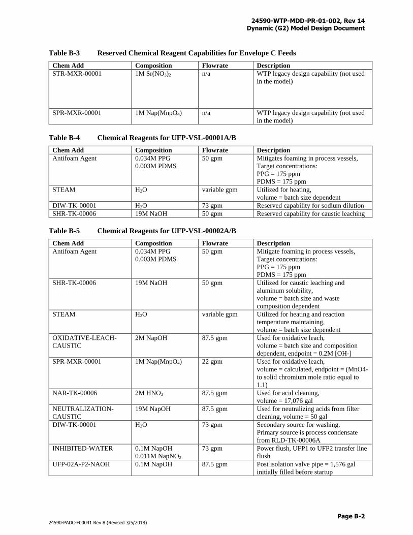
24590-WTP-MDD-PR-01-002, Rev 14 Dynamic (G2) Model Design Document
Page B-2
24590-PADC-F00041 Rev 8 (Revised 3/5/2018)
Table B-3 Reserved Chemical Reagent Capabilities for Envelope C Feeds
Chem Add Composition Flowrate Description
STR-MXR-00001 1M Sr(NO3)2 n/a WTP legacy design capability (not used
in the model)
SPR-MXR-00001 1M Nap(MnpO4) n/a WTP legacy design capability (not used
in the model)
Table B-4 Chemical Reagents for UFP-VSL-00001A/B
Chem Add Composition Flowrate Description
Antifoam Agent 0.034M PPG
0.003M PDMS
50 gpm Mitigates foaming in process vessels,
Target concentrations:
PPG = 175 ppm
PDMS = 175 ppm
STEAM H2O variable gpm Utilized for heating,
volume = batch size dependent
DIW-TK-00001 H2O 73 gpm Reserved capability for sodium dilution
SHR-TK-00006 19M NaOH 50 gpm Reserved capability for caustic leaching
Table B-5 Chemical Reagents for UFP-VSL-00002A/B
Chem Add Composition Flowrate Description
Antifoam Agent 0.034M PPG
0.003M PDMS
50 gpm Mitigate foaming in process vessels,
Target concentrations:
PPG = 175 ppm
PDMS = 175 ppm
SHR-TK-00006 19M NaOH 50 gpm Utilized for caustic leaching and
aluminum solubility,
volume = batch size and waste
composition dependent
STEAM H2O variable gpm Utilized for heating and reaction
temperature maintaining,
volume = batch size dependent
OXIDATIVE-LEACH-
CAUSTIC
2M NapOH 87.5 gpm Used for oxidative leach,
volume = batch size and composition
dependent, endpoint = 0.2M [OH-]
SPR-MXR-00001 1M Nap(MnpO4) 22 gpm Used for oxidative leach,
volume = calculated, endpoint = (MnO4-
to solid chromium mole ratio equal to
1.1)
NAR-TK-00006 2M HNO3 87.5 gpm Used for acid cleaning,
volume = 17,076 gal
NEUTRALIZATION-
CAUSTIC
19M NapOH 87.5 gpm Used for neutralizing acids from filter
cleaning, volume = 50 gal
DIW-TK-00001 H2O 73 gpm Secondary source for washing.
Primary source is process condensate
from RLD-TK-00006A
INHIBITED-WATER 0.1M NapOH
0.011M NapNO2
73 gpm Power flush, UFP1 to UFP2 transfer line
flush
UFP-02A-P2-NAOH 0.1M NapOH 87.5 gpm Post isolation valve pipe = 1,576 gal
initially filled before startup
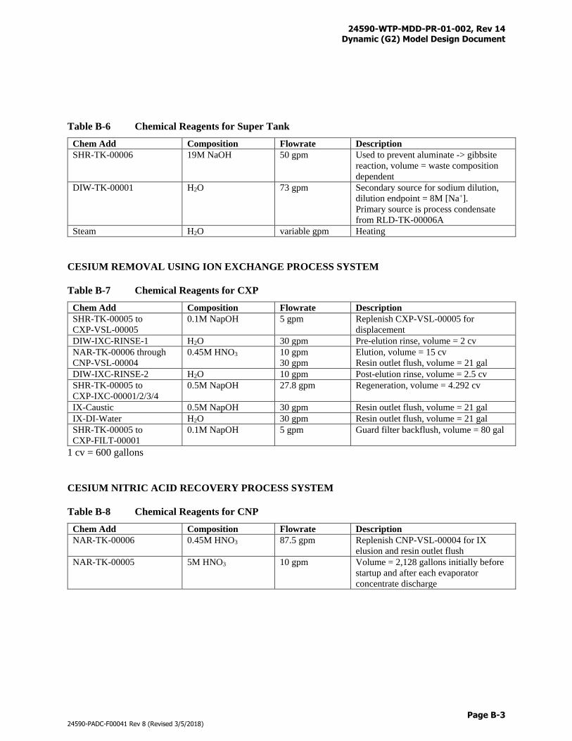
24590-WTP-MDD-PR-01-002, Rev 14 Dynamic (G2) Model Design Document
Page B-3
24590-PADC-F00041 Rev 8 (Revised 3/5/2018)
Table B-6 Chemical Reagents for Super Tank
Chem Add Composition Flowrate Description
SHR-TK-00006 19M NaOH 50 gpm Used to prevent aluminate -> gibbsite
reaction, volume = waste composition
dependent
DIW-TK-00001 H2O 73 gpm Secondary source for sodium dilution,
dilution endpoint = 8M [Na+].
Primary source is process condensate
from RLD-TK-00006A
Steam H2O variable gpm Heating
CESIUM REMOVAL USING ION EXCHANGE PROCESS SYSTEM
Table B-7 Chemical Reagents for CXP
Chem Add Composition Flowrate Description
SHR-TK-00005 to
CXP-VSL-00005
0.1M NapOH 5 gpm Replenish CXP-VSL-00005 for
displacement
DIW-IXC-RINSE-1 H2O 30 gpm Pre-elution rinse, volume = 2 cv
NAR-TK-00006 through
CNP-VSL-00004
0.45M HNO3 10 gpm
30 gpm
Elution, volume = 15 cv
Resin outlet flush, volume = 21 gal
DIW-IXC-RINSE-2 H2O 10 gpm Post-elution rinse, volume = 2.5 cv
SHR-TK-00005 to
CXP-IXC-00001/2/3/4
0.5M NapOH 27.8 gpm Regeneration, volume = 4.292 cv
IX-Caustic 0.5M NapOH 30 gpm Resin outlet flush, volume = 21 gal
IX-DI-Water H2O 30 gpm Resin outlet flush, volume = 21 gal
SHR-TK-00005 to
CXP-FILT-00001
0.1M NapOH 5 gpm Guard filter backflush, volume = 80 gal
1 cv = 600 gallons
CESIUM NITRIC ACID RECOVERY PROCESS SYSTEM
Table B-8 Chemical Reagents for CNP
Chem Add Composition Flowrate Description
NAR-TK-00006 0.45M HNO3 87.5 gpm Replenish CNP-VSL-00004 for IX
elusion and resin outlet flush
NAR-TK-00005 5M HNO3 10 gpm Volume = 2,128 gallons initially before
startup and after each evaporator
concentrate discharge
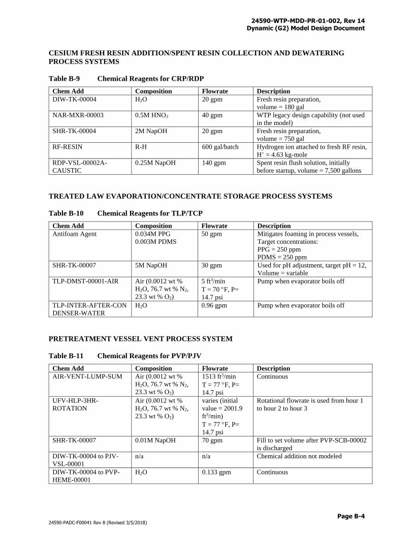
24590-WTP-MDD-PR-01-002, Rev 14 Dynamic (G2) Model Design Document
Page B-4
24590-PADC-F00041 Rev 8 (Revised 3/5/2018)
CESIUM FRESH RESIN ADDITION/SPENT RESIN COLLECTION AND DEWATERING
PROCESS SYSTEMS
Table B-9 Chemical Reagents for CRP/RDP
Chem Add Composition Flowrate Description
DIW-TK-00004 H2O 20 gpm Fresh resin preparation,
volume = 180 gal
NAR-MXR-00003 0.5M HNO3 40 gpm WTP legacy design capability (not used
in the model)
SHR-TK-00004 2M NapOH 20 gpm Fresh resin preparation,
volume = 750 gal
RF-RESIN R-H 600 gal/batch Hydrogen ion attached to fresh RF resin,
H+ = 4.63 kg-mole
RDP-VSL-00002A-
CAUSTIC
0.25M NapOH 140 gpm Spent resin flush solution, initially
before startup, volume = 7,500 gallons
TREATED LAW EVAPORATION/CONCENTRATE STORAGE PROCESS SYSTEMS
Table B-10 Chemical Reagents for TLP/TCP
Chem Add Composition Flowrate Description
Antifoam Agent 0.034M PPG
0.003M PDMS
50 gpm Mitigates foaming in process vessels,
Target concentrations:
PPG = 250 ppm
PDMS = 250 ppm
SHR-TK-00007 5M NapOH 30 gpm Used for pH adjustment, target pH = 12,
Volume = variable
TLP-DMST-00001-AIR Air (0.0012 wt %
H2O, 76.7 wt % N2,
23.3 wt % O2)
5 ft3/min
T = 70 F, P=
14.7 psi
Pump when evaporator boils off
TLP-INTER-AFTER-CON
DENSER-WATER
H2O 0.96 gpm Pump when evaporator boils off
PRETREATMENT VESSEL VENT PROCESS SYSTEM
Table B-11 Chemical Reagents for PVP/PJV
Chem Add Composition Flowrate Description
AIR-VENT-LUMP-SUM Air (0.0012 wt %
H2O, 76.7 wt % N2,
23.3 wt % O2)
1513 ft3/min
T = 77 F, P=
14.7 psi
Continuous
UFV-HLP-3HR-
ROTATION
Air (0.0012 wt %
H2O, 76.7 wt % N2,
23.3 wt % O2)
varies (initial
value = 2001.9
ft3/min)
T = 77 F, P=
14.7 psi
Rotational flowrate is used from hour 1
to hour 2 to hour 3
SHR-TK-00007 0.01M NapOH 70 gpm Fill to set volume after PVP-SCB-00002
is discharged
DIW-TK-00004 to PJV-
VSL-00001
n/a n/a Chemical addition not modeled
DIW-TK-00004 to PVP-
HEME-00001
H2O 0.133 gpm Continuous
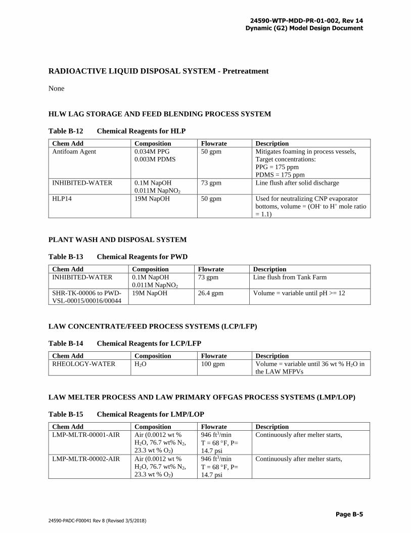
24590-WTP-MDD-PR-01-002, Rev 14 Dynamic (G2) Model Design Document
Page B-5
24590-PADC-F00041 Rev 8 (Revised 3/5/2018)
RADIOACTIVE LIQUID DISPOSAL SYSTEM - Pretreatment
None
HLW LAG STORAGE AND FEED BLENDING PROCESS SYSTEM
Table B-12 Chemical Reagents for HLP
Chem Add Composition Flowrate Description
Antifoam Agent 0.034M PPG
0.003M PDMS
50 gpm Mitigates foaming in process vessels,
Target concentrations:
PPG = 175 ppm
PDMS = 175 ppm
INHIBITED-WATER 0.1M NapOH
0.011M NapNO2
73 gpm Line flush after solid discharge
HLP14 19M NapOH 50 gpm Used for neutralizing CNP evaporator
bottoms, volume = (OH- to H+ mole ratio
= 1.1)
PLANT WASH AND DISPOSAL SYSTEM
Table B-13 Chemical Reagents for PWD
Chem Add Composition Flowrate Description
INHIBITED-WATER 0.1M NapOH
0.011M NapNO2
73 gpm Line flush from Tank Farm
SHR-TK-00006 to PWD-
VSL-00015/00016/00044
19M NapOH 26.4 gpm Volume = variable until pH >= 12
LAW CONCENTRATE/FEED PROCESS SYSTEMS (LCP/LFP)
Table B-14 Chemical Reagents for LCP/LFP
Chem Add Composition Flowrate Description
RHEOLOGY-WATER H2O 100 gpm Volume = variable until 36 wt % H2O in
the LAW MFPVs
LAW MELTER PROCESS AND LAW PRIMARY OFFGAS PROCESS SYSTEMS (LMP/LOP)
Table B-15 Chemical Reagents for LMP/LOP
Chem Add Composition Flowrate Description
LMP-MLTR-00001-AIR
Air (0.0012 wt %
H2O, 76.7 wt% N2,
23.3 wt % O2)
946 ft3/min
T = 68 F, P=
14.7 psi
Continuously after melter starts,
LMP-MLTR-00002-AIR
Air (0.0012 wt %
H2O, 76.7 wt% N2,
23.3 wt % O2)
946 ft3/min
T = 68 F, P=
14.7 psi
Continuously after melter starts,
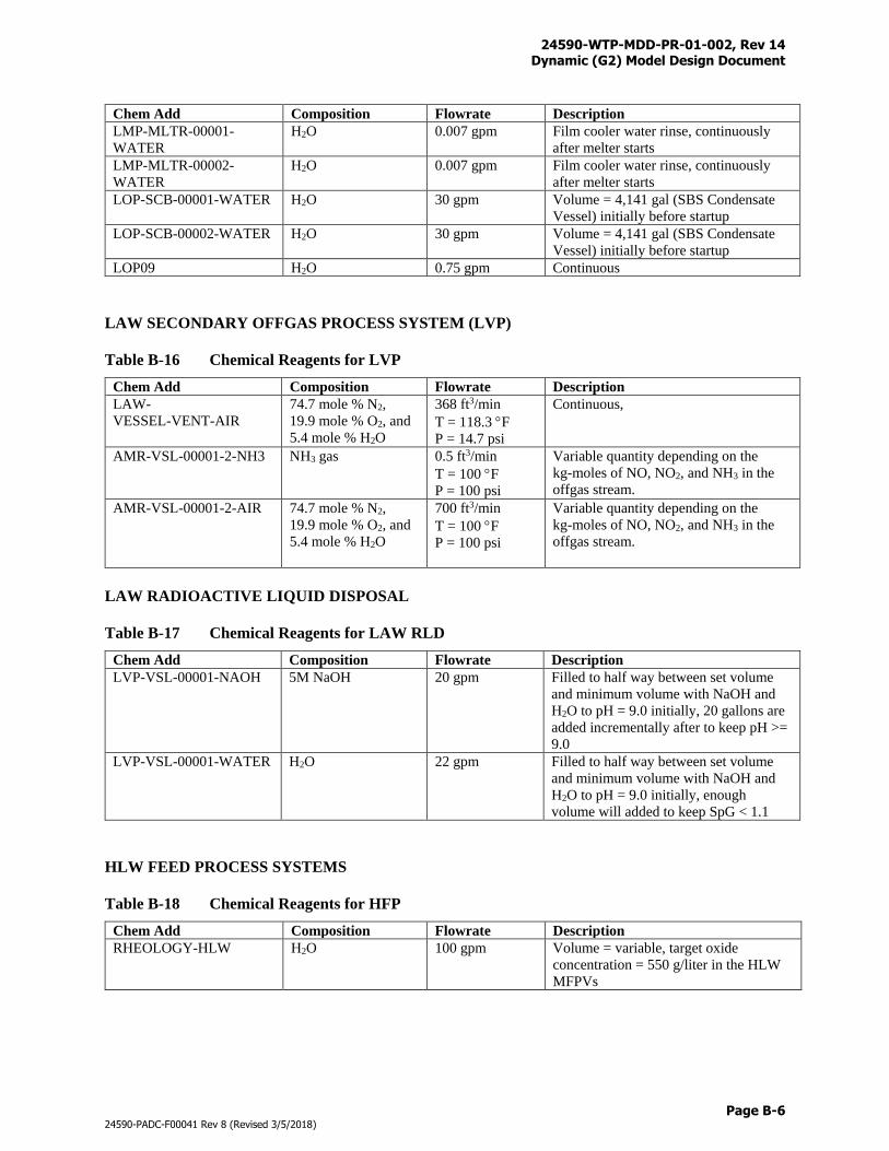
24590-WTP-MDD-PR-01-002, Rev 14 Dynamic (G2) Model Design Document
Page B-6
24590-PADC-F00041 Rev 8 (Revised 3/5/2018)
Chem Add Composition Flowrate Description
LMP-MLTR-00001-
WATER
H2O 0.007 gpm Film cooler water rinse, continuously
after melter starts
LMP-MLTR-00002-
WATER
H2O 0.007 gpm Film cooler water rinse, continuously
after melter starts
LOP-SCB-00001-WATER
H2O 30 gpm Volume = 4,141 gal (SBS Condensate
Vessel) initially before startup
LOP-SCB-00002-WATER H2O 30 gpm Volume = 4,141 gal (SBS Condensate
Vessel) initially before startup
LOP09 H2O 0.75 gpm Continuous
LAW SECONDARY OFFGAS PROCESS SYSTEM (LVP)
Table B-16 Chemical Reagents for LVP
Chem Add Composition Flowrate Description
LAW-
VESSEL-VENT-AIR
74.7 mole % N2,
19.9 mole % O2, and
5.4 mole % H2O
368 ft3/min
T = 118.3 F
P = 14.7 psi
Continuous,
AMR-VSL-00001-2-NH3 NH3 gas 0.5 ft3/min
T = 100 F
P = 100 psi
Variable quantity depending on the
kg-moles of NO, NO2, and NH3 in the
offgas stream.
AMR-VSL-00001-2-AIR 74.7 mole % N2,
19.9 mole % O2, and
5.4 mole % H2O
700 ft3/min
T = 100 F
P = 100 psi
Variable quantity depending on the
kg-moles of NO, NO2, and NH3 in the
offgas stream.
LAW RADIOACTIVE LIQUID DISPOSAL
Table B-17 Chemical Reagents for LAW RLD
Chem Add Composition Flowrate Description
LVP-VSL-00001-NAOH 5M NaOH 20 gpm Filled to half way between set volume
and minimum volume with NaOH and
H2O to pH = 9.0 initially, 20 gallons are
added incrementally after to keep pH >=
9.0
LVP-VSL-00001-WATER H2O 22 gpm Filled to half way between set volume
and minimum volume with NaOH and
H2O to pH = 9.0 initially, enough
volume will added to keep SpG < 1.1
HLW FEED PROCESS SYSTEMS
Table B-18 Chemical Reagents for HFP
Chem Add Composition Flowrate Description
RHEOLOGY-HLW H2O 100 gpm Volume = variable, target oxide
concentration = 550 g/liter in the HLW
MFPVs
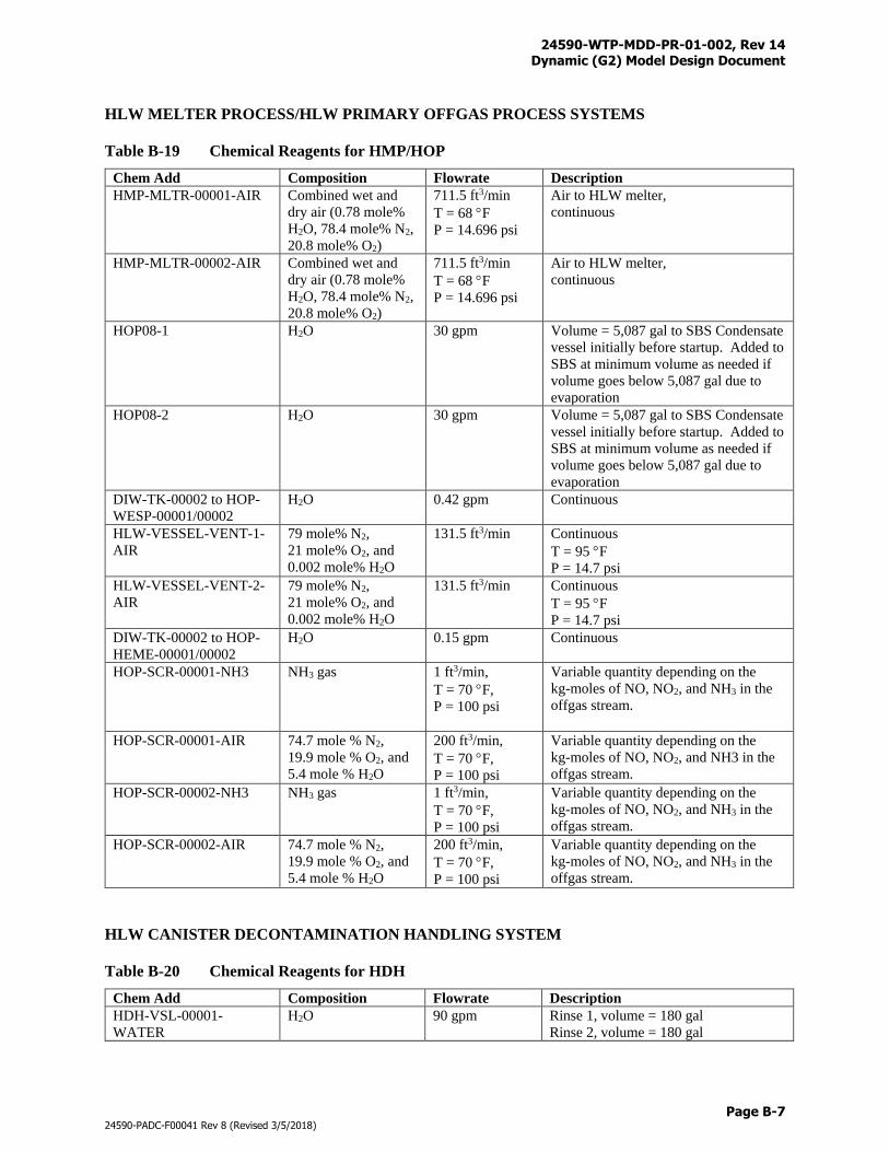
24590-WTP-MDD-PR-01-002, Rev 14 Dynamic (G2) Model Design Document
Page B-7
24590-PADC-F00041 Rev 8 (Revised 3/5/2018)
HLW MELTER PROCESS/HLW PRIMARY OFFGAS PROCESS SYSTEMS
Table B-19 Chemical Reagents for HMP/HOP
Chem Add Composition Flowrate Description
HMP-MLTR-00001-AIR
Combined wet and
dry air (0.78 mole%
H2O, 78.4 mole% N2,
20.8 mole% O2)
711.5 ft3/min
T = 68 F
P = 14.696 psi
Air to HLW melter,
continuous
HMP-MLTR-00002-AIR
Combined wet and
dry air (0.78 mole%
H2O, 78.4 mole% N2,
20.8 mole% O2)
711.5 ft3/min
T = 68 F
P = 14.696 psi
Air to HLW melter,
continuous
HOP08-1 H2O 30 gpm Volume = 5,087 gal to SBS Condensate
vessel initially before startup. Added to
SBS at minimum volume as needed if
volume goes below 5,087 gal due to
evaporation
HOP08-2 H2O 30 gpm Volume = 5,087 gal to SBS Condensate
vessel initially before startup. Added to
SBS at minimum volume as needed if
volume goes below 5,087 gal due to
evaporation
DIW-TK-00002 to HOP-
WESP-00001/00002
H2O 0.42 gpm Continuous
HLW-VESSEL-VENT-1-
AIR
79 mole% N2,
21 mole% O2, and
0.002 mole% H2O
131.5 ft3/min Continuous
T = 95 F
P = 14.7 psi
HLW-VESSEL-VENT-2-
AIR
79 mole% N2,
21 mole% O2, and
0.002 mole% H2O
131.5 ft3/min Continuous
T = 95 F
P = 14.7 psi
DIW-TK-00002 to HOP-
HEME-00001/00002
H2O 0.15 gpm Continuous
HOP-SCR-00001-NH3 NH3 gas 1 ft3/min,
T = 70 F,
P = 100 psi
Variable quantity depending on the
kg-moles of NO, NO2, and NH3 in the
offgas stream.
HOP-SCR-00001-AIR 74.7 mole % N2,
19.9 mole % O2, and
5.4 mole % H2O
200 ft3/min,
T = 70 F,
P = 100 psi
Variable quantity depending on the
kg-moles of NO, NO2, and NH3 in the
offgas stream.
HOP-SCR-00002-NH3 NH3 gas 1 ft3/min,
T = 70 F,
P = 100 psi
Variable quantity depending on the
kg-moles of NO, NO2, and NH3 in the
offgas stream.
HOP-SCR-00002-AIR 74.7 mole % N2,
19.9 mole % O2, and
5.4 mole % H2O
200 ft3/min,
T = 70 F,
P = 100 psi
Variable quantity depending on the
kg-moles of NO, NO2, and NH3 in the
offgas stream.
HLW CANISTER DECONTAMINATION HANDLING SYSTEM
Table B-20 Chemical Reagents for HDH
Chem Add Composition Flowrate Description
HDH-VSL-00001-
WATER
H2O 90 gpm Rinse 1, volume = 180 gal
Rinse 2, volume = 180 gal
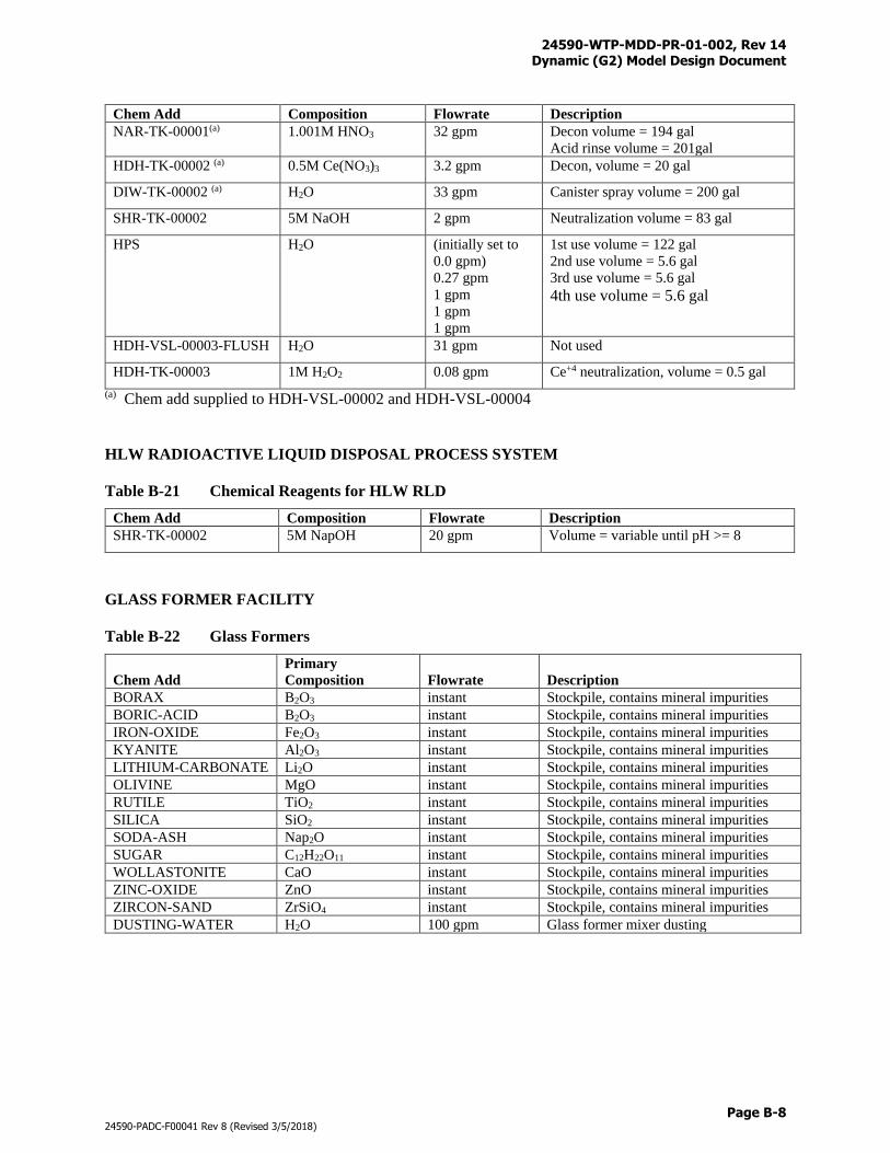
24590-WTP-MDD-PR-01-002, Rev 14 Dynamic (G2) Model Design Document
Page B-8
24590-PADC-F00041 Rev 8 (Revised 3/5/2018)
Chem Add Composition Flowrate Description
NAR-TK-00001(a) 1.001M HNO3 32 gpm Decon volume = 194 gal
Acid rinse volume = 201gal
HDH-TK-00002 (a) 0.5M Ce(NO3)3 3.2 gpm Decon, volume = 20 gal
DIW-TK-00002 (a) H2O 33 gpm Canister spray volume = 200 gal
SHR-TK-00002 5M NaOH 2 gpm Neutralization volume = 83 gal
HPS H2O (initially set to
0.0 gpm)
0.27 gpm
1 gpm
1 gpm
1 gpm
1st use volume = 122 gal
2nd use volume = 5.6 gal
3rd use volume = 5.6 gal
4th use volume = 5.6 gal
HDH-VSL-00003-FLUSH H2O 31 gpm Not used
HDH-TK-00003 1M H2O2 0.08 gpm Ce+4 neutralization, volume = 0.5 gal
(a) Chem add supplied to HDH-VSL-00002 and HDH-VSL-00004
HLW RADIOACTIVE LIQUID DISPOSAL PROCESS SYSTEM
Table B-21 Chemical Reagents for HLW RLD
Chem Add Composition Flowrate Description
SHR-TK-00002 5M NapOH 20 gpm Volume = variable until pH >= 8
GLASS FORMER FACILITY
Table B-22 Glass Formers
Chem Add
Primary
Composition Flowrate Description
BORAX B2O3 instant Stockpile, contains mineral impurities
BORIC-ACID B2O3 instant Stockpile, contains mineral impurities
IRON-OXIDE Fe2O3 instant Stockpile, contains mineral impurities
KYANITE Al2O3 instant Stockpile, contains mineral impurities
LITHIUM-CARBONATE Li2O instant Stockpile, contains mineral impurities
OLIVINE MgO instant Stockpile, contains mineral impurities
RUTILE TiO2 instant Stockpile, contains mineral impurities
SILICA SiO2 instant Stockpile, contains mineral impurities
SODA-ASH Nap2O instant Stockpile, contains mineral impurities
SUGAR C12H22O11 instant Stockpile, contains mineral impurities
WOLLASTONITE CaO instant Stockpile, contains mineral impurities
ZINC-OXIDE ZnO instant Stockpile, contains mineral impurities
ZIRCON-SAND ZrSiO4 instant Stockpile, contains mineral impurities
DUSTING-WATER H2O 100 gpm Glass former mixer dusting
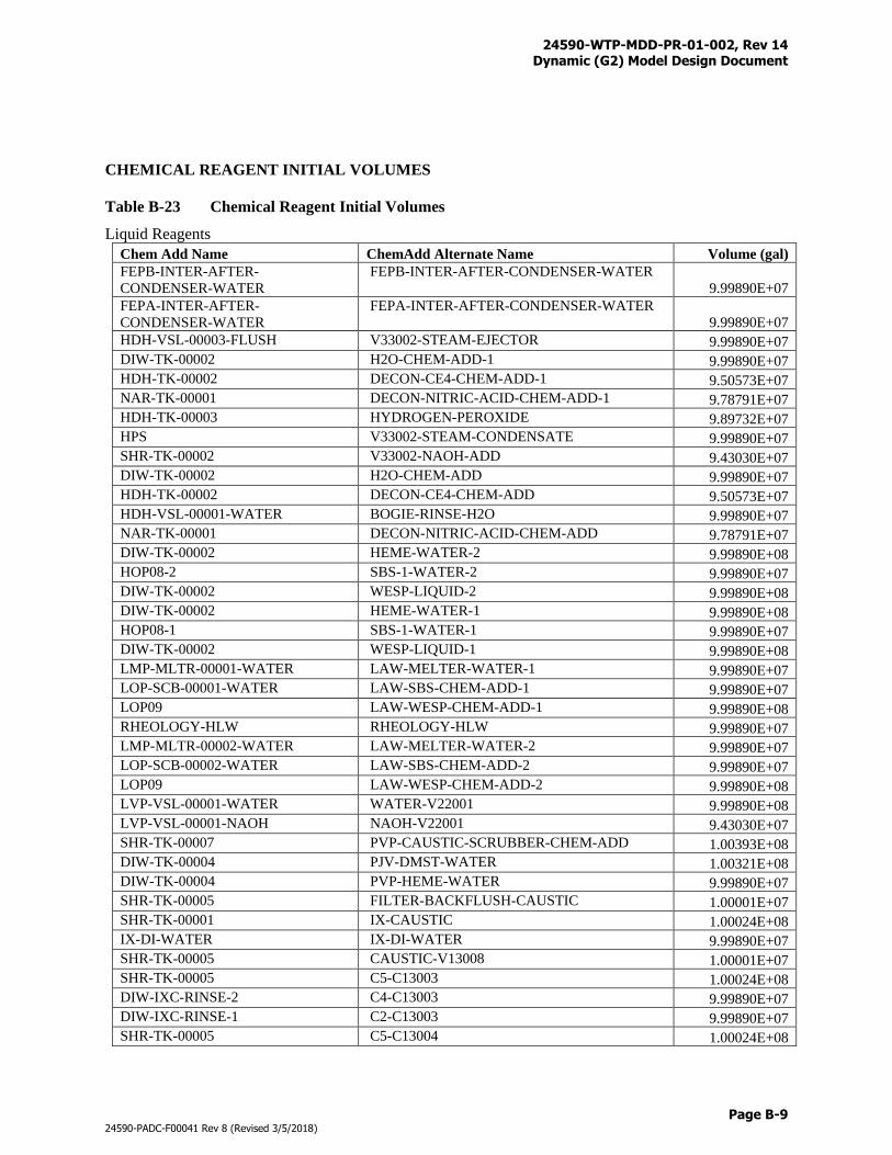
24590-WTP-MDD-PR-01-002, Rev 14 Dynamic (G2) Model Design Document
Page B-9
24590-PADC-F00041 Rev 8 (Revised 3/5/2018)
CHEMICAL REAGENT INITIAL VOLUMES
Table B-23 Chemical Reagent Initial Volumes
Liquid Reagents
Chem Add Name ChemAdd Alternate Name Volume (gal)
FEPB-INTER-AFTER-
CONDENSER-WATER
FEPB-INTER-AFTER-CONDENSER-WATER
9.99890E+07
FEPA-INTER-AFTER-
CONDENSER-WATER
FEPA-INTER-AFTER-CONDENSER-WATER
9.99890E+07
HDH-VSL-00003-FLUSH V33002-STEAM-EJECTOR 9.99890E+07
DIW-TK-00002 H2O-CHEM-ADD-1 9.99890E+07
HDH-TK-00002 DECON-CE4-CHEM-ADD-1 9.50573E+07
NAR-TK-00001 DECON-NITRIC-ACID-CHEM-ADD-1 9.78791E+07
HDH-TK-00003 HYDROGEN-PEROXIDE 9.89732E+07
HPS V33002-STEAM-CONDENSATE 9.99890E+07
SHR-TK-00002 V33002-NAOH-ADD 9.43030E+07
DIW-TK-00002 H2O-CHEM-ADD 9.99890E+07
HDH-TK-00002 DECON-CE4-CHEM-ADD 9.50573E+07
HDH-VSL-00001-WATER BOGIE-RINSE-H2O 9.99890E+07
NAR-TK-00001 DECON-NITRIC-ACID-CHEM-ADD 9.78791E+07
DIW-TK-00002 HEME-WATER-2 9.99890E+08
HOP08-2 SBS-1-WATER-2 9.99890E+07
DIW-TK-00002 WESP-LIQUID-2 9.99890E+08
DIW-TK-00002 HEME-WATER-1 9.99890E+08
HOP08-1 SBS-1-WATER-1 9.99890E+07
DIW-TK-00002 WESP-LIQUID-1 9.99890E+08
LMP-MLTR-00001-WATER LAW-MELTER-WATER-1 9.99890E+07
LOP-SCB-00001-WATER LAW-SBS-CHEM-ADD-1 9.99890E+07
LOP09 LAW-WESP-CHEM-ADD-1 9.99890E+08
RHEOLOGY-HLW RHEOLOGY-HLW 9.99890E+07
LMP-MLTR-00002-WATER LAW-MELTER-WATER-2 9.99890E+07
LOP-SCB-00002-WATER LAW-SBS-CHEM-ADD-2 9.99890E+07
LOP09 LAW-WESP-CHEM-ADD-2 9.99890E+08
LVP-VSL-00001-WATER WATER-V22001 9.99890E+08
LVP-VSL-00001-NAOH NAOH-V22001 9.43030E+07
SHR-TK-00007 PVP-CAUSTIC-SCRUBBER-CHEM-ADD 1.00393E+08
DIW-TK-00004 PJV-DMST-WATER 1.00321E+08
DIW-TK-00004 PVP-HEME-WATER 9.99890E+07
SHR-TK-00005 FILTER-BACKFLUSH-CAUSTIC 1.00001E+07
SHR-TK-00001 IX-CAUSTIC 1.00024E+08
IX-DI-WATER IX-DI-WATER 9.99890E+07
SHR-TK-00005 CAUSTIC-V13008 1.00001E+07
SHR-TK-00005 C5-C13003 1.00024E+08
DIW-IXC-RINSE-2 C4-C13003 9.99890E+07
DIW-IXC-RINSE-1 C2-C13003 9.99890E+07
SHR-TK-00005 C5-C13004 1.00024E+08
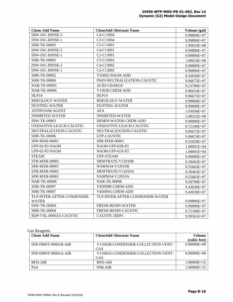
24590-WTP-MDD-PR-01-002, Rev 14 Dynamic (G2) Model Design Document
Page B-10
24590-PADC-F00041 Rev 8 (Revised 3/5/2018)
Chem Add Name ChemAdd Alternate Name Volume (gal)
DIW-IXC-RINSE-2 C4-C13004 9.99890E+07
DIW-IXC-RINSE-1 C2-C13004 9.99890E+07
SHR-TK-00005 C5-C13001 1.00024E+08
DIW-IXC-RINSE-2 C4-C13001 9.99890E+07
DIW-IXC-RINSE-1 C2-C13001 9.99890E+07
SHR-TK-00005 C5-C13002 1.00024E+08
DIW-IXC-RINSE-2 C4-C13002 9.99890E+07
DIW-IXC-RINSE-1 C2-C13002 9.99890E+07
SHR-TK-00002 V35002-NAOH-ADD 9.43030E+07
SHR-TK-00006 PWD-NEUTRALIZATION-CAUSTIC 9.06675E+07
NAR-TK-00005 ACID-CHARGE 9.23799E+07
NAR-TK-00006 V13028-CHEM-ADD 9.90054E+07
HLP14 HLP14 9.06675E+07
RHEOLOGY-WATER RHEOLOGY-WATER 9.99890E+07
DUSTING-WATER DUSTING-WATER 9.99890E+07
ANTIFOAM-AGENT AFA 1.03036E+07
INHIBITED-WATER INHIBITED-WATER 2.08252E+08
DIW-TK-00001 DEMIN-WATER-CHEM-ADD 9.99890E+07
OXIDATIVE-LEACH-CAUSTIC OXIDATIVE-LEACH-CAUSTIC 9.72108E+07
NEUTRALIZATION-CAUSTIC NEUTRALIZATION-CAUSTIC 9.06675E+07
SHR-TK-00006 UFP-CAUSTIC 9.06674E+07
SPR-MXR-00001 SPR-MXR-00001 9.55658E+07
UFP-02-P2-NAOH NAOH-UFP-02B-P2 1.00001E+04
UFP-02-P2-NAOH NAOH-UFP-02A-P2 1.00001E+04
STEAM UFP-STEAM 9.99890E+07
STR-MXR-00001 SRNITRATE-V12010B 9.39463E+07
SPR-MXR-00001 NAMNO4-V12010B 9.55663E+07
STR-MXR-00001 SRNITRATE-V12010A 9.39463E+07
SPR-MXR-00001 NAMNO4-V12010A 9.55663E+07
NAR-TK-00006 NAR-TK-00006 9.59799E+07
SHR-TK-00007 V45009B-CHEM-ADD 9.43030E+07
SHR-TK-00007 V45009A-CHEM-ADD 9.43030E+07
TLP-INTER-AFTER-CONDENSER-
WATER
TLP-INTER-AFTER-CONDENSER-WATER
9.99890E+07
DIW-TK-00004 FRESH-RESIN-WATER 9.99890E+07
SHR-TK-00004 FRESH-RESIN-CAUSTIC 9.72108E+07
RDP-VSL-00002A-CAUSTIC CAUSTIC-RDP1 9.99361E+07
Gas Reagents Chem Add Name ChemAdd Alternate Name Volume
(cubic feet)
FEP-DMST-00001B-AIR V11002B-CONDENSER-COLLECTION-VENT-
GAS
9.99999E+09
FEP-DMST-00001A-AIR V11002A-CONDENSER-COLLECTION-VENT-
GAS
9.99999E+09
RFD-AIR RFD-AIR 1.00000E+15
PSA PJM-AIR 1.00000E+15
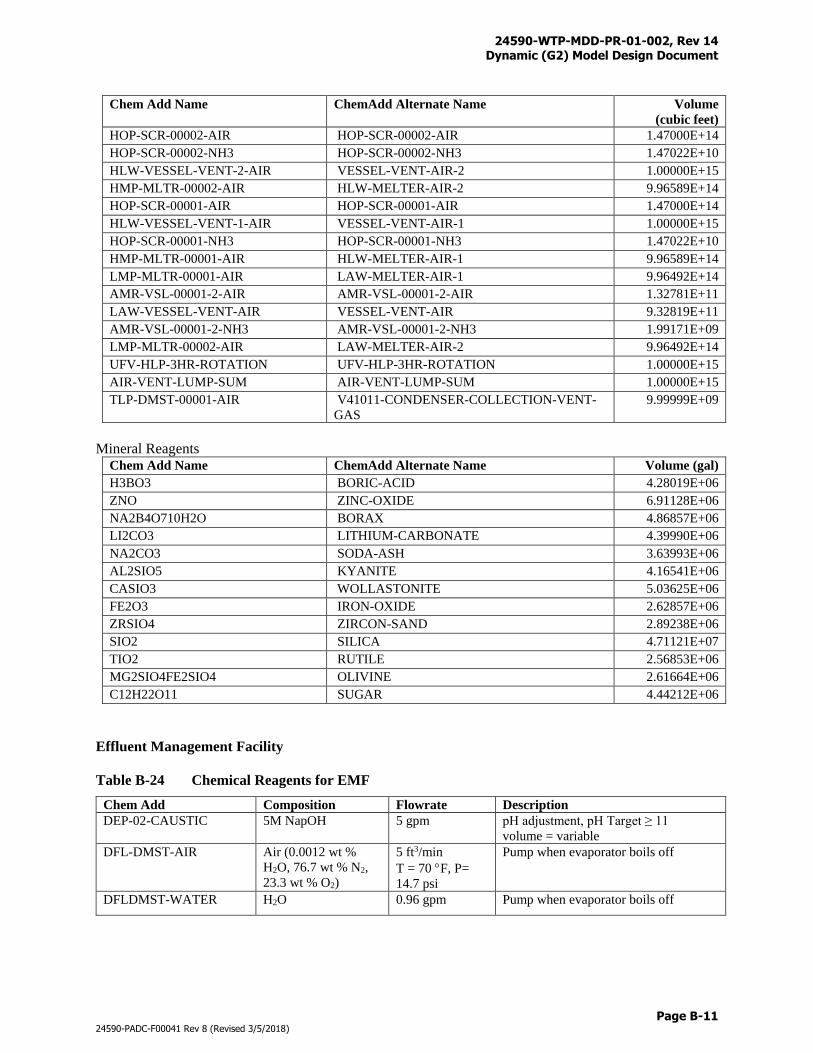
24590-WTP-MDD-PR-01-002, Rev 14 Dynamic (G2) Model Design Document
Page B-11
24590-PADC-F00041 Rev 8 (Revised 3/5/2018)
Chem Add Name ChemAdd Alternate Name Volume
(cubic feet)
HOP-SCR-00002-AIR HOP-SCR-00002-AIR 1.47000E+14
HOP-SCR-00002-NH3 HOP-SCR-00002-NH3 1.47022E+10
HLW-VESSEL-VENT-2-AIR VESSEL-VENT-AIR-2 1.00000E+15
HMP-MLTR-00002-AIR HLW-MELTER-AIR-2 9.96589E+14
HOP-SCR-00001-AIR HOP-SCR-00001-AIR 1.47000E+14
HLW-VESSEL-VENT-1-AIR VESSEL-VENT-AIR-1 1.00000E+15
HOP-SCR-00001-NH3 HOP-SCR-00001-NH3 1.47022E+10
HMP-MLTR-00001-AIR HLW-MELTER-AIR-1 9.96589E+14
LMP-MLTR-00001-AIR LAW-MELTER-AIR-1 9.96492E+14
AMR-VSL-00001-2-AIR AMR-VSL-00001-2-AIR 1.32781E+11
LAW-VESSEL-VENT-AIR VESSEL-VENT-AIR 9.32819E+11
AMR-VSL-00001-2-NH3 AMR-VSL-00001-2-NH3 1.99171E+09
LMP-MLTR-00002-AIR LAW-MELTER-AIR-2 9.96492E+14
UFV-HLP-3HR-ROTATION UFV-HLP-3HR-ROTATION 1.00000E+15
AIR-VENT-LUMP-SUM AIR-VENT-LUMP-SUM 1.00000E+15
TLP-DMST-00001-AIR V41011-CONDENSER-COLLECTION-VENT-
GAS
9.99999E+09
Mineral Reagents Chem Add Name ChemAdd Alternate Name Volume (gal)
H3BO3 BORIC-ACID 4.28019E+06
ZNO ZINC-OXIDE 6.91128E+06
NA2B4O710H2O BORAX 4.86857E+06
LI2CO3 LITHIUM-CARBONATE 4.39990E+06
NA2CO3 SODA-ASH 3.63993E+06
AL2SIO5 KYANITE 4.16541E+06
CASIO3 WOLLASTONITE 5.03625E+06
FE2O3 IRON-OXIDE 2.62857E+06
ZRSIO4 ZIRCON-SAND 2.89238E+06
SIO2 SILICA 4.71121E+07
TIO2 RUTILE 2.56853E+06
MG2SIO4FE2SIO4 OLIVINE 2.61664E+06
C12H22O11 SUGAR 4.44212E+06
Effluent Management Facility
Table B-24 Chemical Reagents for EMF
Chem Add Composition Flowrate Description
DEP-02-CAUSTIC 5M NapOH 5 gpm pH adjustment, pH Target ≥ 11
volume = variable
DFL-DMST-AIR Air (0.0012 wt %
H2O, 76.7 wt % N2,
23.3 wt % O2)
5 ft3/min
T = 70 F, P=
14.7 psi
Pump when evaporator boils off
DFLDMST-WATER H2O 0.96 gpm Pump when evaporator boils off
24590-WTP-MDD-PR-01-002, Rev 14 Dynamic (G2) Model Design Document
Page C-i
24590-PADC-F00041 Rev 8 (Revised 3/5/2018)
Appendix C
Sample Identification and Logic
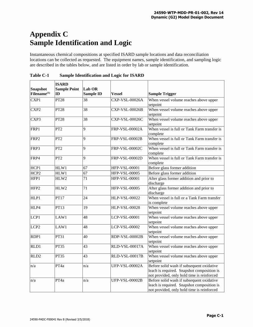
24590-WTP-MDD-PR-01-002, Rev 14 Dynamic (G2) Model Design Document
Page C-1
24590-PADC-F00041 Rev 8 (Revised 3/5/2018)
Appendix C
Sample Identification and Logic
Instantaneous chemical compositions at specified ISARD sample locations and data reconciliation
locations can be collected as requested. The equipment names, sample identification, and sampling logic
are described in the tables below, and are listed in order by lab or sample identification.
Table C-1 Sample Identification and Logic for ISARD
Snapshot
Filename(1)
ISARD
Sample Point
ID
Lab OR
Sample ID Vessel Sample Trigger
CXP1 PT28 38 CXP-VSL-00026A When vessel volume reaches above upper
setpoint
CXP2 PT28 38 CXP-VSL-00026B When vessel volume reaches above upper
setpoint
CXP3 PT28 38 CXP-VSL-00026C When vessel volume reaches above upper
setpoint
FRP1 PT2 9 FRP-VSL-00002A When vessel is full or Tank Farm transfer is
complete
FRP2 PT2 9 FRP-VSL-00002B When vessel is full or Tank Farm transfer is
complete
FRP3 PT2 9 FRP-VSL-00002C When vessel is full or Tank Farm transfer is
complete
FRP4 PT2 9 FRP-VSL-00002D When vessel is full or Tank Farm transfer is
complete
HCP1 HLW1 67 HFP-VSL-00001 Before glass former addition
HCP2 HLW1 67 HFP-VSL-00005 Before glass former addition
HFP1 HLW2 71 HFP-VSL-00001 After glass former addition and prior to
discharge
HFP2 HLW2 71 HFP-VSL-00005 After glass former addition and prior to
discharge
HLP1 PT17 24 HLP-VSL-00022 When vessel is full or a Tank Farm transfer
is complete
HLP4 PT13 19 HLP-VSL-00028 When vessel volume reaches above upper
setpoint
LCP1 LAW1 48 LCP-VSL-00001 When vessel volume reaches above upper
setpoint
LCP2 LAW1 48 LCP-VSL-00002 When vessel volume reaches above upper
setpoint
RDP1 PT31 40 RDP-VSL-00002B When vessel volume reaches above upper
setpoint
RLD1 PT35 43 RLD-VSL-00017A When vessel volume reaches above upper
setpoint
RLD2 PT35 43 RLD-VSL-00017B When vessel volume reaches above upper
setpoint
n/a PT4a n/a UFP-VSL-00002A Before solid wash if subsequent oxidative
leach is required. Snapshot composition is
not provided, only hold time is reinforced
n/a PT4a n/a UFP-VSL-00002B Before solid wash if subsequent oxidative
leach is required. Snapshot composition is
not provided, only hold time is reinforced
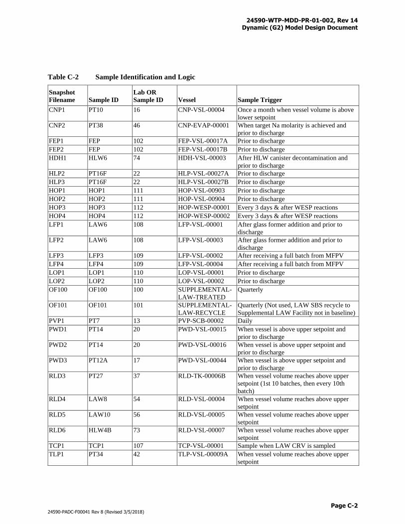
24590-WTP-MDD-PR-01-002, Rev 14 Dynamic (G2) Model Design Document
Page C-2
24590-PADC-F00041 Rev 8 (Revised 3/5/2018)
Table C-2 Sample Identification and Logic
Snapshot
Filename Sample ID
Lab OR
Sample ID Vessel Sample Trigger
CNP1 PT10 16 CNP-VSL-00004 Once a month when vessel volume is above
lower setpoint
CNP2 PT38 46 CNP-EVAP-00001 When target Na molarity is achieved and
prior to discharge
FEP1 FEP 102 FEP-VSL-00017A Prior to discharge
FEP2 FEP 102 FEP-VSL-00017B Prior to discharge
HDH1 HLW6 74 HDH-VSL-00003 After HLW canister decontamination and
prior to discharge
HLP2 PT16F 22 HLP-VSL-00027A Prior to discharge
HLP3 PT16F 22 HLP-VSL-00027B Prior to discharge
HOP1 HOP1 111 HOP-VSL-00903 Prior to discharge
HOP2 HOP2 111 HOP-VSL-00904 Prior to discharge
HOP3 HOP3 112 HOP-WESP-00001 Every 3 days & after WESP reactions
HOP4 HOP4 112 HOP-WESP-00002 Every 3 days & after WESP reactions
LFP1 LAW6 108 LFP-VSL-00001 After glass former addition and prior to
discharge
LFP2 LAW6 108 LFP-VSL-00003 After glass former addition and prior to
discharge
LFP3 LFP3 109 LFP-VSL-00002 After receiving a full batch from MFPV
LFP4 LFP4 109 LFP-VSL-00004 After receiving a full batch from MFPV
LOP1 LOP1 110 LOP-VSL-00001 Prior to discharge
LOP2 LOP2 110 LOP-VSL-00002 Prior to discharge
OF100 OF100 100 SUPPLEMENTAL-
LAW-TREATED
Quarterly
OF101 OF101 101 SUPPLEMENTAL-
LAW-RECYCLE
Quarterly (Not used, LAW SBS recycle to
Supplemental LAW Facility not in baseline)
PVP1 PT7 13 PVP-SCB-00002 Daily
PWD1 PT14 20 PWD-VSL-00015 When vessel is above upper setpoint and
prior to discharge
PWD2 PT14 20 PWD-VSL-00016 When vessel is above upper setpoint and
prior to discharge
PWD3 PT12A 17 PWD-VSL-00044 When vessel is above upper setpoint and
prior to discharge
RLD3 PT27 37 RLD-TK-00006B When vessel volume reaches above upper
setpoint (1st 10 batches, then every 10th
batch)
RLD4 LAW8 54 RLD-VSL-00004 When vessel volume reaches above upper
setpoint
RLD5 LAW10 56 RLD-VSL-00005 When vessel volume reaches above upper
setpoint
RLD6 HLW4B 73 RLD-VSL-00007 When vessel volume reaches above upper
setpoint
TCP1 TCP1 107 TCP-VSL-00001 Sample when LAW CRV is sampled
TLP1 PT34 42 TLP-VSL-00009A When vessel volume reaches above upper
setpoint
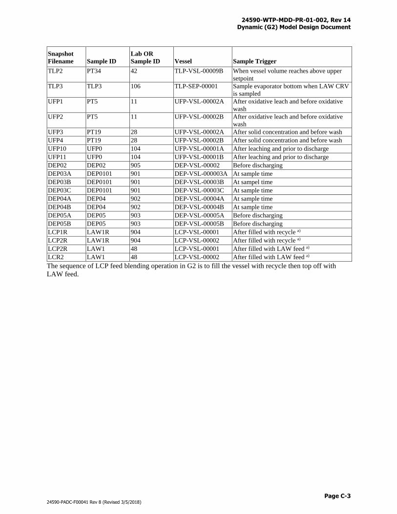
24590-WTP-MDD-PR-01-002, Rev 14 Dynamic (G2) Model Design Document
Page C-3
24590-PADC-F00041 Rev 8 (Revised 3/5/2018)
Snapshot
Filename Sample ID
Lab OR
Sample ID Vessel Sample Trigger
TLP2 PT34 42 TLP-VSL-00009B When vessel volume reaches above upper
setpoint
TLP3 TLP3 106 TLP-SEP-00001 Sample evaporator bottom when LAW CRV
is sampled
UFP1 PT5 11 UFP-VSL-00002A After oxidative leach and before oxidative
wash
UFP2 PT5 11 UFP-VSL-00002B After oxidative leach and before oxidative
wash
UFP3 PT19 28 UFP-VSL-00002A After solid concentration and before wash
UFP4 PT19 28 UFP-VSL-00002B After solid concentration and before wash
UFP10 UFP0 104 UFP-VSL-00001A After leaching and prior to discharge
UFP11 UFP0 104 UFP-VSL-00001B After leaching and prior to discharge
DEP02 DEP02 905 DEP-VSL-00002 Before discharging
DEP03A DEP0101 901 DEP-VSL-000003A At sample time
DEP03B DEP0101 901 DEP-VSL-00003B At sampel time
DEP03C DEP0101 901 DEP-VSL-00003C At sample time
DEP04A DEP04 902 DEP-VSL-00004A At sample time
DEP04B DEP04 902 DEP-VSL-00004B At sample time
DEP05A DEP05 903 DEP-VSL-00005A Before discharging
DEP05B DEP05 903 DEP-VSL-00005B Before discharging
LCP1R LAW1R 904 LCP-VSL-00001 After filled with recycle a)
LCP2R LAW1R 904 LCP-VSL-00002 After filled with recycle a)
LCP2R LAW1 48 LCP-VSL-00001 After filled with LAW feed a)
LCR2 LAW1 48 LCP-VSL-00002 After filled with LAW feed a)
The sequence of LCP feed blending operation in G2 is to fill the vessel with recycle then top off with
LAW feed.
24590-WTP-MDD-PR-01-002, Rev 14 Dynamic (G2) Model Design Document
Page D-i
24590-PADC-F00041 Rev 8 (Revised 3/5/2018)
Appendix D
Component Splits
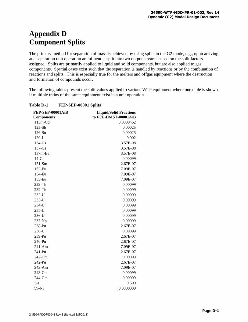
24590-WTP-MDD-PR-01-002, Rev 14 Dynamic (G2) Model Design Document
Page D-1
24590-PADC-F00041 Rev 8 (Revised 3/5/2018)
Appendix D
Component Splits
The primary method for separation of mass is achieved by using splits in the G2 mode, e.g., upon arriving
at a separation unit operation an influent is split into two output streams based on the split factors
assigned. Splits are primarily applied to liquid and solid components, but are also applied to gas
components. Special cases exist such that the separation is handled by reactions or by the combination of
reactions and splits. This is especially true for the melters and offgas equipment where the destruction
and formation of compounds occur.
The following tables present the split values applied to various WTP equipment where one table is shown
if multiple trains of the same equipment exist in a unit operation.
Table D-1 FEP-SEP-00001 Splits
FEP-SEP-00001A/B
Components
Liquid/Solid Fractions
to FEP-DMST-00001A/B
113m-Cd 0.0000452
125-Sb 0.00025
126-Sn 0.00025
129-I 0.002
134-Cs 3.57E-08
137-Cs 3.57E-08
137m-Ba 3.57E-08
14-C 0.00099
151-Sm 2.67E-07
152-Eu 7.09E-07
154-Eu 7.09E-07
155-Eu 7.09E-07
229-Th 0.00099
232-Th 0.00099
232-U 0.00099
233-U 0.00099
234-U 0.00099
235-U 0.00099
236-U 0.00099
237-Np 0.00099
238-Pu 2.67E-07
238-U 0.00099
239-Pu 2.67E-07
240-Pu 2.67E-07
241-Am 7.09E-07
241-Pu 2.67E-07
242-Cm 0.00099
242-Pu 2.67E-07
243-Am 7.09E-07
243-Cm 0.00099
244-Cm 0.00099
3-H 0.599
59-Ni 0.0000339
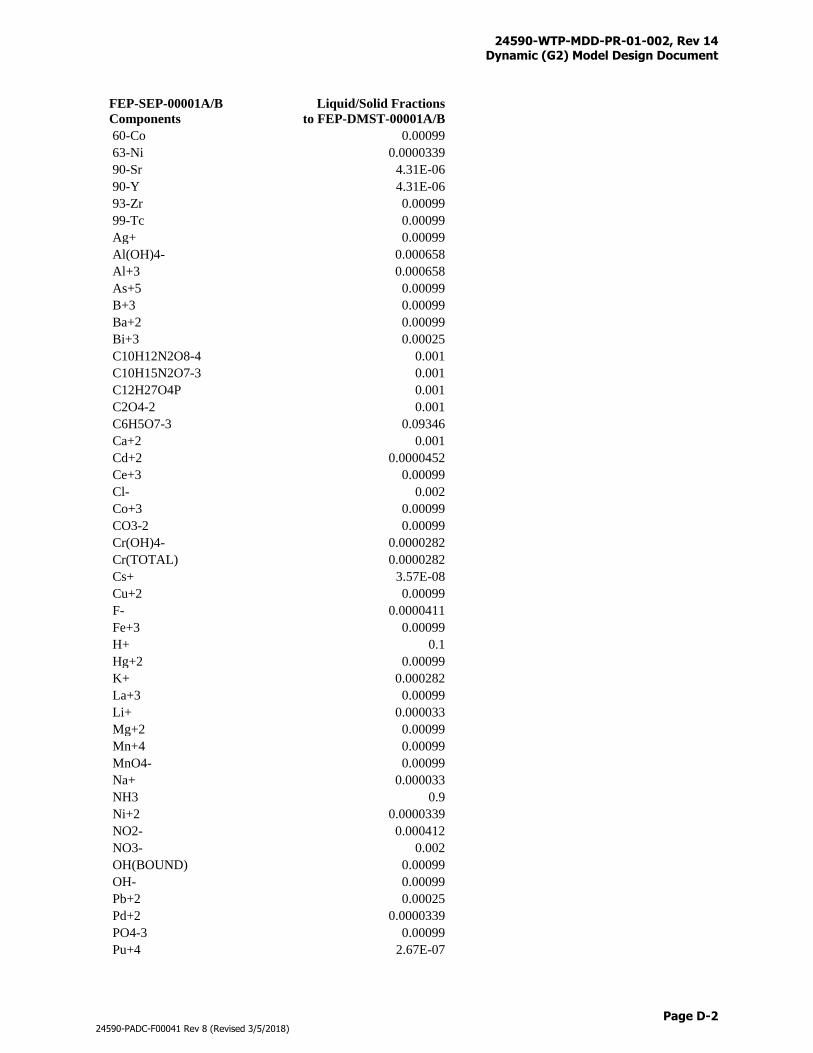
24590-WTP-MDD-PR-01-002, Rev 14 Dynamic (G2) Model Design Document
Page D-2
24590-PADC-F00041 Rev 8 (Revised 3/5/2018)
FEP-SEP-00001A/B
Components
Liquid/Solid Fractions
to FEP-DMST-00001A/B
60-Co 0.00099
63-Ni 0.0000339
90-Sr 4.31E-06
90-Y 4.31E-06
93-Zr 0.00099
99-Tc 0.00099
Ag+ 0.00099
Al(OH)4- 0.000658
Al+3 0.000658
As+5 0.00099
B+3 0.00099
Ba+2 0.00099
Bi+3 0.00025
C10H12N2O8-4 0.001
C10H15N2O7-3 0.001
C12H27O4P 0.001
C2O4-2 0.001
C6H5O7-3 0.09346
Ca+2 0.001
Cd+2 0.0000452
Ce+3 0.00099
Cl- 0.002
Co+3 0.00099
CO3-2 0.00099
Cr(OH)4- 0.0000282
Cr(TOTAL) 0.0000282
Cs+ 3.57E-08
Cu+2 0.00099
F- 0.0000411
Fe+3 0.00099
H+ 0.1
Hg+2 0.00099
K+ 0.000282
La+3 0.00099
Li+ 0.000033
Mg+2 0.00099
Mn+4 0.00099
MnO4- 0.00099
Na+ 0.000033
NH3 0.9
Ni+2 0.0000339
NO2- 0.000412
NO3- 0.002
OH(BOUND) 0.00099
OH- 0.00099
Pb+2 0.00025
Pd+2 0.0000339
PO4-3 0.00099
Pu+4 2.67E-07
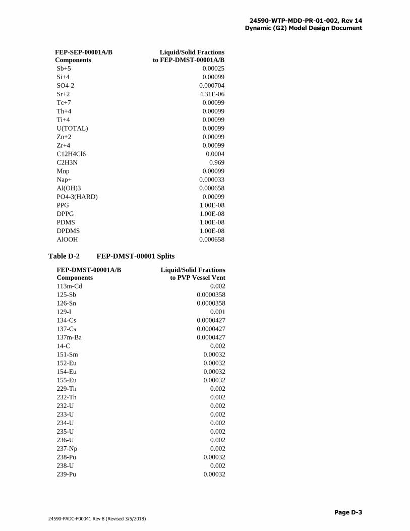
24590-WTP-MDD-PR-01-002, Rev 14 Dynamic (G2) Model Design Document
Page D-3
24590-PADC-F00041 Rev 8 (Revised 3/5/2018)
FEP-SEP-00001A/B
Components
Liquid/Solid Fractions
to FEP-DMST-00001A/B
Sb+5 0.00025
Si+4 0.00099
SO4-2 0.000704
Sr+2 4.31E-06
Tc+7 0.00099
Th+4 0.00099
Ti+4 0.00099
U(TOTAL) 0.00099
Zn+2 0.00099
Zr+4 0.00099
C12H4Cl6 0.0004
C2H3N 0.969
Mnp 0.00099
Nap+ 0.000033
Al(OH)3 0.000658
PO4-3(HARD) 0.00099
PPG 1.00E-08
DPPG 1.00E-08
PDMS 1.00E-08
DPDMS 1.00E-08
AlOOH 0.000658
Table D-2 FEP-DMST-00001 Splits
FEP-DMST-00001A/B
Components
Liquid/Solid Fractions
to PVP Vessel Vent
113m-Cd 0.002
125-Sb 0.0000358
126-Sn 0.0000358
129-I 0.001
134-Cs 0.0000427
137-Cs 0.0000427
137m-Ba 0.0000427
14-C 0.002
151-Sm 0.00032
152-Eu 0.00032
154-Eu 0.00032
155-Eu 0.00032
229-Th 0.002
232-Th 0.002
232-U 0.002
233-U 0.002
234-U 0.002
235-U 0.002
236-U 0.002
237-Np 0.002
238-Pu 0.00032
238-U 0.002
239-Pu 0.00032
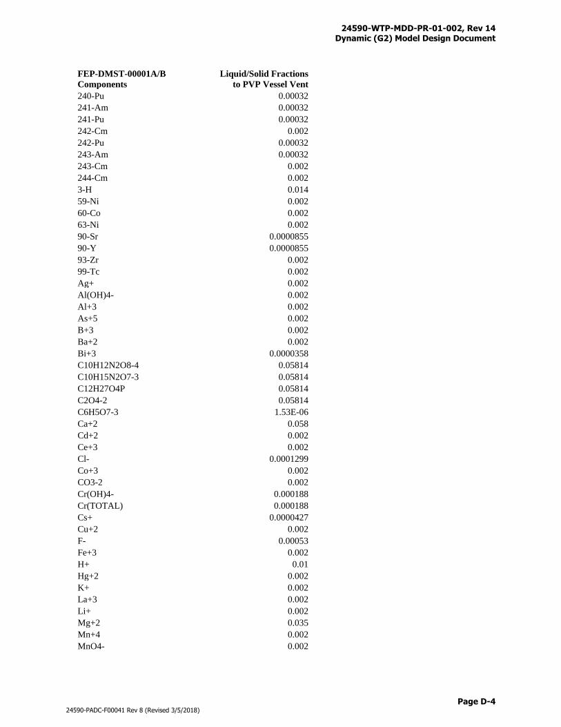
24590-WTP-MDD-PR-01-002, Rev 14 Dynamic (G2) Model Design Document
Page D-4
24590-PADC-F00041 Rev 8 (Revised 3/5/2018)
FEP-DMST-00001A/B
Components
Liquid/Solid Fractions
to PVP Vessel Vent
240-Pu 0.00032
241-Am 0.00032
241-Pu 0.00032
242-Cm 0.002
242-Pu 0.00032
243-Am 0.00032
243-Cm 0.002
244-Cm 0.002
3-H 0.014
59-Ni 0.002
60-Co 0.002
63-Ni 0.002
90-Sr 0.0000855
90-Y 0.0000855
93-Zr 0.002
99-Tc 0.002
Ag+ 0.002
Al(OH)4- 0.002
Al+3 0.002
As+5 0.002
B+3 0.002
Ba+2 0.002
Bi+3 0.0000358
C10H12N2O8-4 0.05814
C10H15N2O7-3 0.05814
C12H27O4P 0.05814
C2O4-2 0.05814
C6H5O7-3 1.53E-06
Ca+2 0.058
Cd+2 0.002
Ce+3 0.002
Cl- 0.0001299
Co+3 0.002
CO3-2 0.002
Cr(OH)4- 0.000188
Cr(TOTAL) 0.000188
Cs+ 0.0000427
Cu+2 0.002
F- 0.00053
Fe+3 0.002
H+ 0.01
Hg+2 0.002
K+ 0.002
La+3 0.002
Li+ 0.002
Mg+2 0.035
Mn+4 0.002
MnO4- 0.002
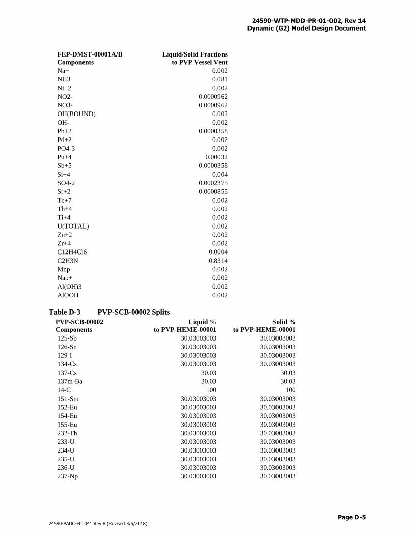
24590-WTP-MDD-PR-01-002, Rev 14 Dynamic (G2) Model Design Document
Page D-5
24590-PADC-F00041 Rev 8 (Revised 3/5/2018)
FEP-DMST-00001A/B
Components
Liquid/Solid Fractions
to PVP Vessel Vent
Na+ 0.002
NH3 0.081
Ni+2 0.002
NO2- 0.0000962
NO3- 0.0000962
OH(BOUND) 0.002
OH- 0.002
Pb+2 0.0000358
Pd+2 0.002
PO4-3 0.002
Pu+4 0.00032
Sb+5 0.0000358
Si+4 0.004
SO4-2 0.0002375
Sr+2 0.0000855
Tc+7 0.002
Th+4 0.002
Ti+4 0.002
U(TOTAL) 0.002
Zn+2 0.002
Zr+4 0.002
C12H4Cl6 0.0004
C2H3N 0.8314
Mnp 0.002
Nap+ 0.002
Al(OH)3 0.002
AlOOH 0.002
Table D-3 PVP-SCB-00002 Splits
PVP-SCB-00002
Components
Liquid %
to PVP-HEME-00001
Solid %
to PVP-HEME-00001
125-Sb 30.03003003 30.03003003
126-Sn 30.03003003 30.03003003
129-I 30.03003003 30.03003003
134-Cs 30.03003003 30.03003003
137-Cs 30.03 30.03
137m-Ba 30.03 30.03
14-C 100 100
151-Sm 30.03003003 30.03003003
152-Eu 30.03003003 30.03003003
154-Eu 30.03003003 30.03003003
155-Eu 30.03003003 30.03003003
232-Th 30.03003003 30.03003003
233-U 30.03003003 30.03003003
234-U 30.03003003 30.03003003
235-U 30.03003003 30.03003003
236-U 30.03003003 30.03003003
237-Np 30.03003003 30.03003003
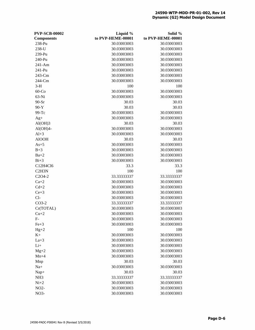
24590-WTP-MDD-PR-01-002, Rev 14 Dynamic (G2) Model Design Document
Page D-6
24590-PADC-F00041 Rev 8 (Revised 3/5/2018)
PVP-SCB-00002
Components
Liquid %
to PVP-HEME-00001
Solid %
to PVP-HEME-00001
238-Pu 30.03003003 30.03003003
238-U 30.03003003 30.03003003
239-Pu 30.03003003 30.03003003
240-Pu 30.03003003 30.03003003
241-Am 30.03003003 30.03003003
241-Pu 30.03003003 30.03003003
243-Cm 30.03003003 30.03003003
244-Cm 30.03003003 30.03003003
3-H 100 100
60-Co 30.03003003 30.03003003
63-Ni 30.03003003 30.03003003
90-Sr 30.03 30.03
90-Y 30.03 30.03
99-Tc 30.03003003 30.03003003
Ag+ 30.03003003 30.03003003
Al(OH)3 30.03 30.03
Al(OH)4- 30.03003003 30.03003003
Al+3 30.03003003 30.03003003
AlOOH 30.03 30.03
As+5 30.03003003 30.03003003
B+3 30.03003003 30.03003003
Ba+2 30.03003003 30.03003003
Bi+3 30.03003003 30.03003003
C12H4Cl6 33.3 33.3
C2H3N 100 100
C2O4-2 33.33333337 33.33333337
Ca+2 30.03003003 30.03003003
Cd+2 30.03003003 30.03003003
Ce+3 30.03003003 30.03003003
Cl- 30.03003003 30.03003003
CO3-2 33.33333337 33.33333337
Cr(TOTAL) 30.03003003 30.03003003
Cu+2 30.03003003 30.03003003
F- 30.03003003 30.03003003
Fe+3 30.03003003 30.03003003
Hg+2 100 100
K+ 30.03003003 30.03003003
La+3 30.03003003 30.03003003
Li+ 30.03003003 30.03003003
Mg+2 30.03003003 30.03003003
Mn+4 30.03003003 30.03003003
Mnp 30.03 30.03
Na+ 30.03003003 30.03003003
Nap+ 30.03 30.03
NH3 33.33333337 33.33333337
Ni+2 30.03003003 30.03003003
NO2- 30.03003003 30.03003003
NO3- 30.03003003 30.03003003
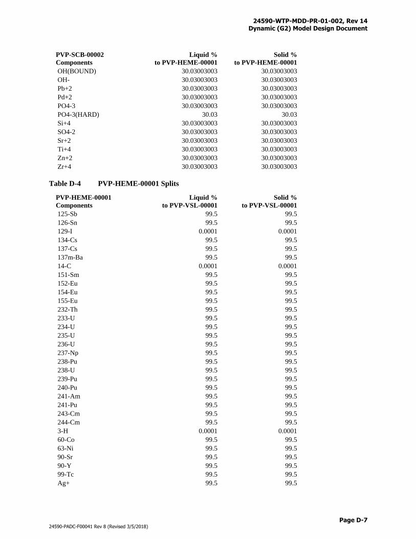
24590-WTP-MDD-PR-01-002, Rev 14 Dynamic (G2) Model Design Document
Page D-7
24590-PADC-F00041 Rev 8 (Revised 3/5/2018)
PVP-SCB-00002
Components
Liquid %
to PVP-HEME-00001
Solid %
to PVP-HEME-00001
OH(BOUND) 30.03003003 30.03003003
OH- 30.03003003 30.03003003
Pb+2 30.03003003 30.03003003
Pd+2 30.03003003 30.03003003
PO4-3 30.03003003 30.03003003
PO4-3(HARD) 30.03 30.03
Si+4 30.03003003 30.03003003
SO4-2 30.03003003 30.03003003
Sr+2 30.03003003 30.03003003
Ti+4 30.03003003 30.03003003
Zn+2 30.03003003 30.03003003
Zr+4 30.03003003 30.03003003
Table D-4 PVP-HEME-00001 Splits
PVP-HEME-00001
Components
Liquid %
to PVP-VSL-00001
Solid %
to PVP-VSL-00001
125-Sb 99.5 99.5
126-Sn 99.5 99.5
129-I 0.0001 0.0001
134-Cs 99.5 99.5
137-Cs 99.5 99.5
137m-Ba 99.5 99.5
14-C 0.0001 0.0001
151-Sm 99.5 99.5
152-Eu 99.5 99.5
154-Eu 99.5 99.5
155-Eu 99.5 99.5
232-Th 99.5 99.5
233-U 99.5 99.5
234-U 99.5 99.5
235-U 99.5 99.5
236-U 99.5 99.5
237-Np 99.5 99.5
238-Pu 99.5 99.5
238-U 99.5 99.5
239-Pu 99.5 99.5
240-Pu 99.5 99.5
241-Am 99.5 99.5
241-Pu 99.5 99.5
243-Cm 99.5 99.5
244-Cm 99.5 99.5
3-H 0.0001 0.0001
60-Co 99.5 99.5
63-Ni 99.5 99.5
90-Sr 99.5 99.5
90-Y 99.5 99.5
99-Tc 99.5 99.5
Ag+ 99.5 99.5
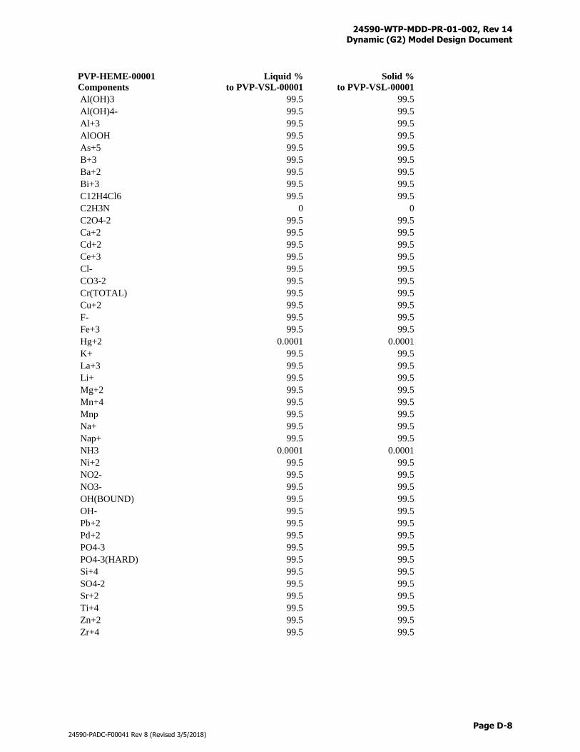
24590-WTP-MDD-PR-01-002, Rev 14 Dynamic (G2) Model Design Document
Page D-8
24590-PADC-F00041 Rev 8 (Revised 3/5/2018)
PVP-HEME-00001
Components
Liquid %
to PVP-VSL-00001
Solid %
to PVP-VSL-00001
Al(OH)3 99.5 99.5
Al(OH)4- 99.5 99.5
Al+3 99.5 99.5
AlOOH 99.5 99.5
As+5 99.5 99.5
B+3 99.5 99.5
Ba+2 99.5 99.5
Bi+3 99.5 99.5
C12H4Cl6 99.5 99.5
C2H3N 0 0
C2O4-2 99.5 99.5
Ca+2 99.5 99.5
Cd+2 99.5 99.5
Ce+3 99.5 99.5
Cl- 99.5 99.5
CO3-2 99.5 99.5
Cr(TOTAL) 99.5 99.5
Cu+2 99.5 99.5
F- 99.5 99.5
Fe+3 99.5 99.5
Hg+2 0.0001 0.0001
K+ 99.5 99.5
La+3 99.5 99.5
Li+ 99.5 99.5
Mg+2 99.5 99.5
Mn+4 99.5 99.5
Mnp 99.5 99.5
Na+ 99.5 99.5
Nap+ 99.5 99.5
NH3 0.0001 0.0001
Ni+2 99.5 99.5
NO2- 99.5 99.5
NO3- 99.5 99.5
OH(BOUND) 99.5 99.5
OH- 99.5 99.5
Pb+2 99.5 99.5
Pd+2 99.5 99.5
PO4-3 99.5 99.5
PO4-3(HARD) 99.5 99.5
Si+4 99.5 99.5
SO4-2 99.5 99.5
Sr+2 99.5 99.5
Ti+4 99.5 99.5
Zn+2 99.5 99.5
Zr+4 99.5 99.5
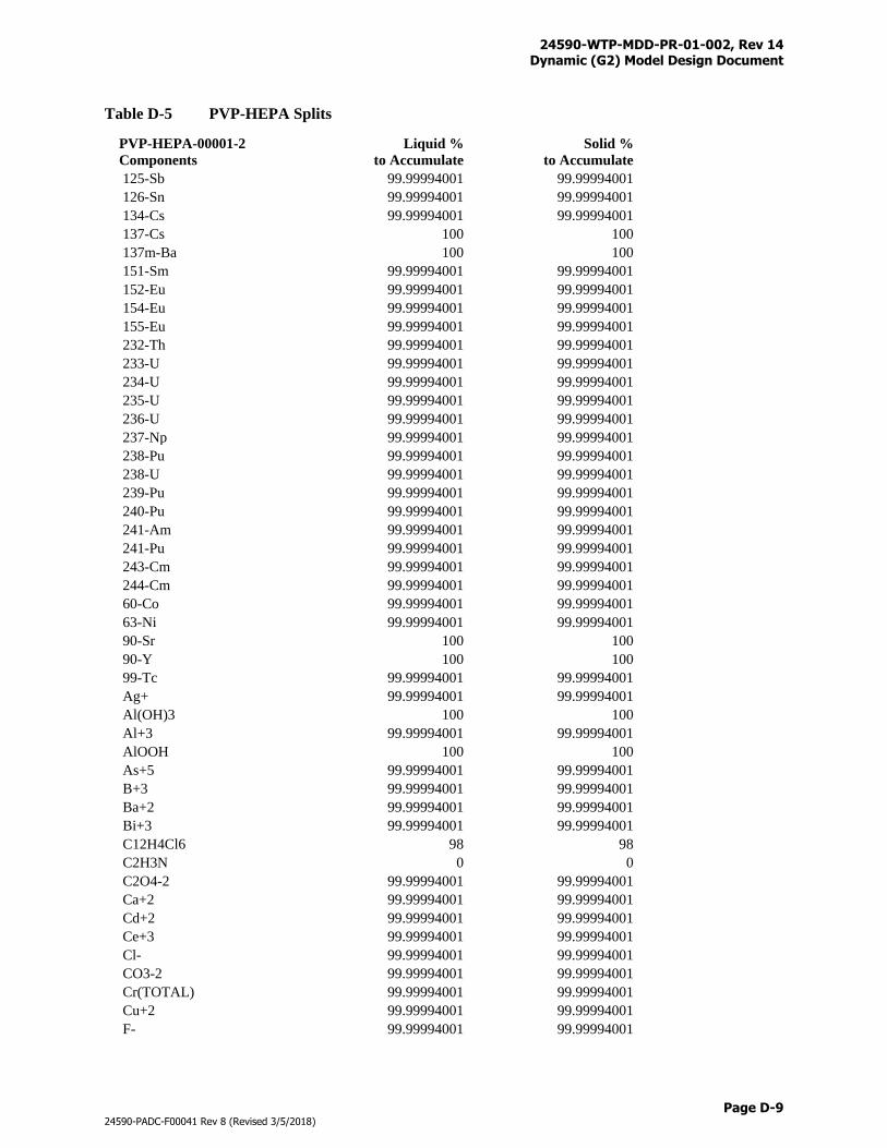
24590-WTP-MDD-PR-01-002, Rev 14 Dynamic (G2) Model Design Document
Page D-9
24590-PADC-F00041 Rev 8 (Revised 3/5/2018)
Table D-5 PVP-HEPA Splits
PVP-HEPA-00001-2
Components
Liquid %
to Accumulate
Solid %
to Accumulate
125-Sb 99.99994001 99.99994001
126-Sn 99.99994001 99.99994001
134-Cs 99.99994001 99.99994001
137-Cs 100 100
137m-Ba 100 100
151-Sm 99.99994001 99.99994001
152-Eu 99.99994001 99.99994001
154-Eu 99.99994001 99.99994001
155-Eu 99.99994001 99.99994001
232-Th 99.99994001 99.99994001
233-U 99.99994001 99.99994001
234-U 99.99994001 99.99994001
235-U 99.99994001 99.99994001
236-U 99.99994001 99.99994001
237-Np 99.99994001 99.99994001
238-Pu 99.99994001 99.99994001
238-U 99.99994001 99.99994001
239-Pu 99.99994001 99.99994001
240-Pu 99.99994001 99.99994001
241-Am 99.99994001 99.99994001
241-Pu 99.99994001 99.99994001
243-Cm 99.99994001 99.99994001
244-Cm 99.99994001 99.99994001
60-Co 99.99994001 99.99994001
63-Ni 99.99994001 99.99994001
90-Sr 100 100
90-Y 100 100
99-Tc 99.99994001 99.99994001
Ag+ 99.99994001 99.99994001
Al(OH)3 100 100
Al+3 99.99994001 99.99994001
AlOOH 100 100
As+5 99.99994001 99.99994001
B+3 99.99994001 99.99994001
Ba+2 99.99994001 99.99994001
Bi+3 99.99994001 99.99994001
C12H4Cl6 98 98
C2H3N 0 0
C2O4-2 99.99994001 99.99994001
Ca+2 99.99994001 99.99994001
Cd+2 99.99994001 99.99994001
Ce+3 99.99994001 99.99994001
Cl- 99.99994001 99.99994001
CO3-2 99.99994001 99.99994001
Cr(TOTAL) 99.99994001 99.99994001
Cu+2 99.99994001 99.99994001
F- 99.99994001 99.99994001
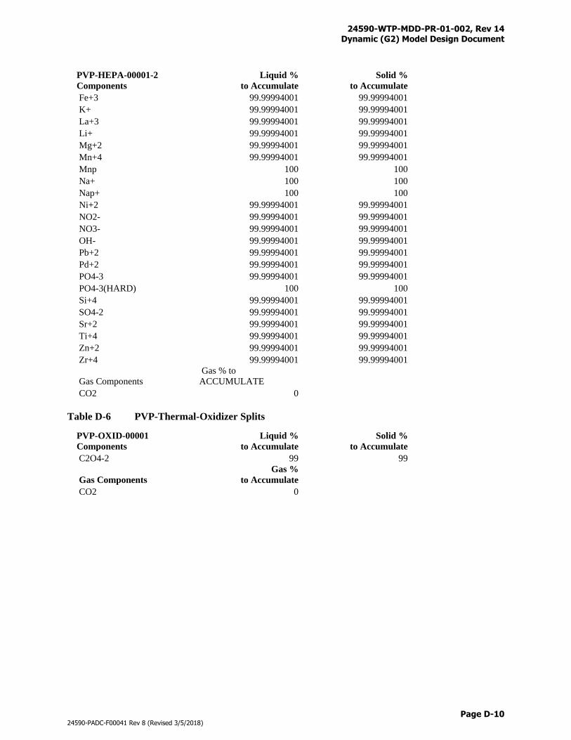
24590-WTP-MDD-PR-01-002, Rev 14 Dynamic (G2) Model Design Document
Page D-10
24590-PADC-F00041 Rev 8 (Revised 3/5/2018)
PVP-HEPA-00001-2
Components
Liquid %
to Accumulate
Solid %
to Accumulate
Fe+3 99.99994001 99.99994001
K+ 99.99994001 99.99994001
La+3 99.99994001 99.99994001
Li+ 99.99994001 99.99994001
Mg+2 99.99994001 99.99994001
Mn+4 99.99994001 99.99994001
Mnp 100 100
Na+ 100 100
Nap+ 100 100
Ni+2 99.99994001 99.99994001
NO2- 99.99994001 99.99994001
NO3- 99.99994001 99.99994001
OH- 99.99994001 99.99994001
Pb+2 99.99994001 99.99994001
Pd+2 99.99994001 99.99994001
PO4-3 99.99994001 99.99994001
PO4-3(HARD) 100 100
Si+4 99.99994001 99.99994001
SO4-2 99.99994001 99.99994001
Sr+2 99.99994001 99.99994001
Ti+4 99.99994001 99.99994001
Zn+2 99.99994001 99.99994001
Zr+4 99.99994001 99.99994001
Gas Components
Gas % to
ACCUMULATE
CO2 0
Table D-6 PVP-Thermal-Oxidizer Splits
PVP-OXID-00001
Components
Liquid %
to Accumulate
Solid %
to Accumulate
C2O4-2 99 99
Gas Components
Gas %
to Accumulate
CO2 0
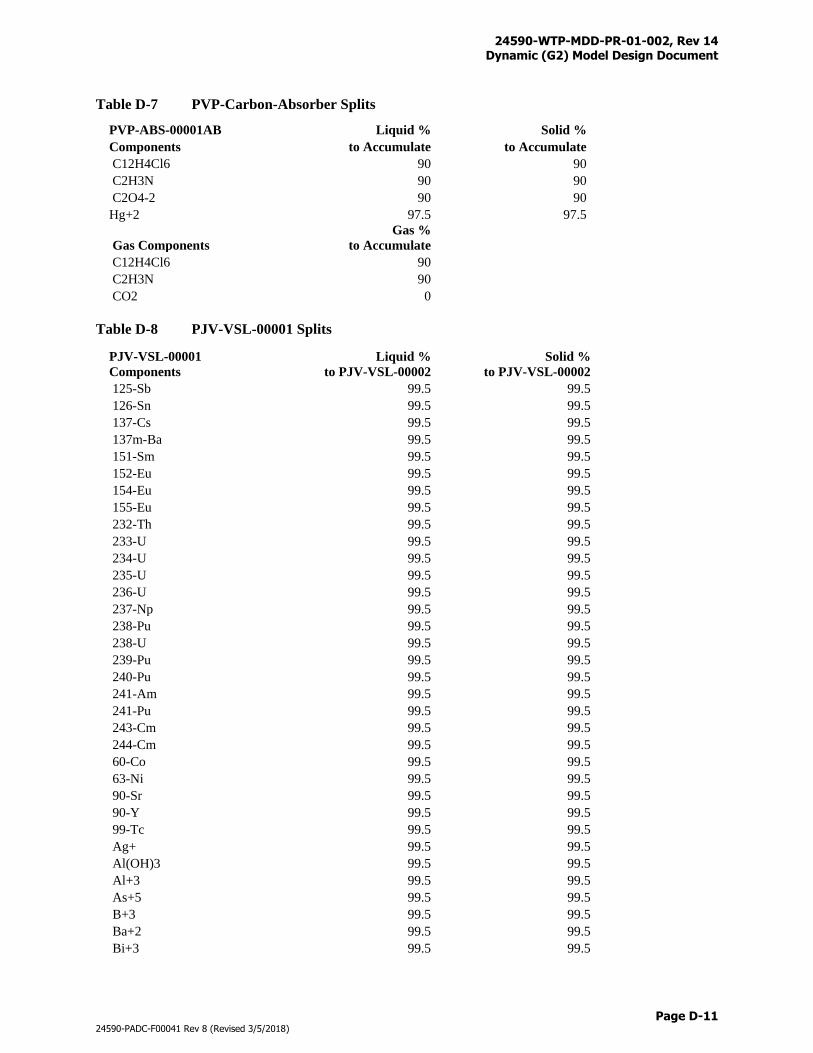
24590-WTP-MDD-PR-01-002, Rev 14 Dynamic (G2) Model Design Document
Page D-11
24590-PADC-F00041 Rev 8 (Revised 3/5/2018)
Table D-7 PVP-Carbon-Absorber Splits
PVP-ABS-00001AB Liquid % Solid %
Components to Accumulate to Accumulate
C12H4Cl6 90 90
C2H3N 90 90
C2O4-2 90 90
Hg+2 97.5 97.5
Gas Components
Gas %
to Accumulate
C12H4Cl6 90
C2H3N 90
CO2 0
Table D-8 PJV-VSL-00001 Splits
PJV-VSL-00001
Components
Liquid %
to PJV-VSL-00002
Solid %
to PJV-VSL-00002
125-Sb 99.5 99.5
126-Sn 99.5 99.5
137-Cs 99.5 99.5
137m-Ba 99.5 99.5
151-Sm 99.5 99.5
152-Eu 99.5 99.5
154-Eu 99.5 99.5
155-Eu 99.5 99.5
232-Th 99.5 99.5
233-U 99.5 99.5
234-U 99.5 99.5
235-U 99.5 99.5
236-U 99.5 99.5
237-Np 99.5 99.5
238-Pu 99.5 99.5
238-U 99.5 99.5
239-Pu 99.5 99.5
240-Pu 99.5 99.5
241-Am 99.5 99.5
241-Pu 99.5 99.5
243-Cm 99.5 99.5
244-Cm 99.5 99.5
60-Co 99.5 99.5
63-Ni 99.5 99.5
90-Sr 99.5 99.5
90-Y 99.5 99.5
99-Tc 99.5 99.5
Ag+ 99.5 99.5
Al(OH)3 99.5 99.5
Al+3 99.5 99.5
As+5 99.5 99.5
B+3 99.5 99.5
Ba+2 99.5 99.5
Bi+3 99.5 99.5
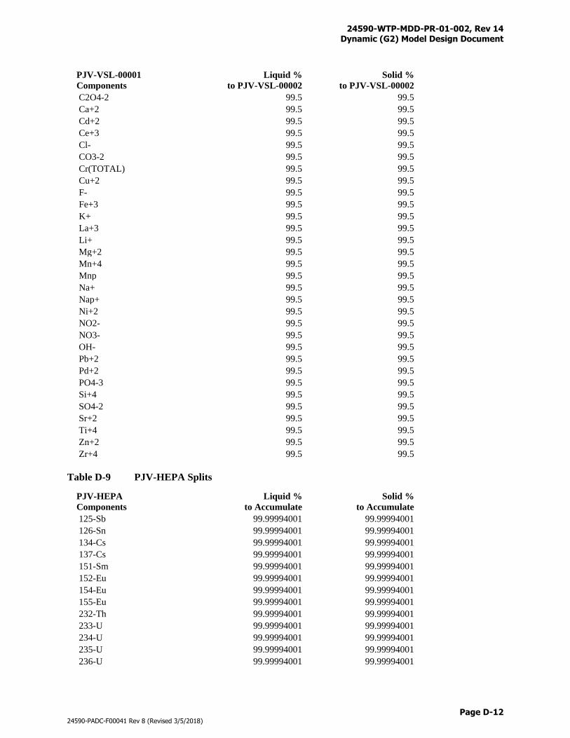
24590-WTP-MDD-PR-01-002, Rev 14 Dynamic (G2) Model Design Document
Page D-12
24590-PADC-F00041 Rev 8 (Revised 3/5/2018)
PJV-VSL-00001
Components
Liquid %
to PJV-VSL-00002
Solid %
to PJV-VSL-00002
C2O4-2 99.5 99.5
Ca+2 99.5 99.5
Cd+2 99.5 99.5
Ce+3 99.5 99.5
Cl- 99.5 99.5
CO3-2 99.5 99.5
Cr(TOTAL) 99.5 99.5
Cu+2 99.5 99.5
F- 99.5 99.5
Fe+3 99.5 99.5
K+ 99.5 99.5
La+3 99.5 99.5
Li+ 99.5 99.5
Mg+2 99.5 99.5
Mn+4 99.5 99.5
Mnp 99.5 99.5
Na+ 99.5 99.5
Nap+ 99.5 99.5
Ni+2 99.5 99.5
NO2- 99.5 99.5
NO3- 99.5 99.5
OH- 99.5 99.5
Pb+2 99.5 99.5
Pd+2 99.5 99.5
PO4-3 99.5 99.5
Si+4 99.5 99.5
SO4-2 99.5 99.5
Sr+2 99.5 99.5
Ti+4 99.5 99.5
Zn+2 99.5 99.5
Zr+4 99.5 99.5
Table D-9 PJV-HEPA Splits
PJV-HEPA
Components
Liquid %
to Accumulate
Solid %
to Accumulate
125-Sb 99.99994001 99.99994001
126-Sn 99.99994001 99.99994001
134-Cs 99.99994001 99.99994001
137-Cs 99.99994001 99.99994001
151-Sm 99.99994001 99.99994001
152-Eu 99.99994001 99.99994001
154-Eu 99.99994001 99.99994001
155-Eu 99.99994001 99.99994001
232-Th 99.99994001 99.99994001
233-U 99.99994001 99.99994001
234-U 99.99994001 99.99994001
235-U 99.99994001 99.99994001
236-U 99.99994001 99.99994001
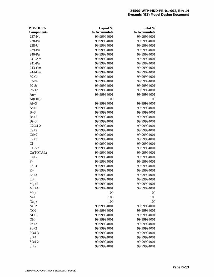
24590-WTP-MDD-PR-01-002, Rev 14 Dynamic (G2) Model Design Document
Page D-13
24590-PADC-F00041 Rev 8 (Revised 3/5/2018)
PJV-HEPA
Components
Liquid %
to Accumulate
Solid %
to Accumulate
237-Np 99.99994001 99.99994001
238-Pu 99.99994001 99.99994001
238-U 99.99994001 99.99994001
239-Pu 99.99994001 99.99994001
240-Pu 99.99994001 99.99994001
241-Am 99.99994001 99.99994001
241-Pu 99.99994001 99.99994001
243-Cm 99.99994001 99.99994001
244-Cm 99.99994001 99.99994001
60-Co 99.99994001 99.99994001
63-Ni 99.99994001 99.99994001
90-Sr 99.99994001 99.99994001
99-Tc 99.99994001 99.99994001
Ag+ 99.99994001 99.99994001
Al(OH)3 100 100
Al+3 99.99994001 99.99994001
As+5 99.99994001 99.99994001
B+3 99.99994001 99.99994001
Ba+2 99.99994001 99.99994001
Bi+3 99.99994001 99.99994001
C2O4-2 99.99994001 99.99994001
Ca+2 99.99994001 99.99994001
Cd+2 99.99994001 99.99994001
Ce+3 99.99994001 99.99994001
Cl- 99.99994001 99.99994001
CO3-2 99.99994001 99.99994001
Cr(TOTAL) 99.99994001 99.99994001
Cu+2 99.99994001 99.99994001
F- 99.99994001 99.99994001
Fe+3 99.99994001 99.99994001
K+ 99.99994001 99.99994001
La+3 99.99994001 99.99994001
Li+ 99.99994001 99.99994001
Mg+2 99.99994001 99.99994001
Mn+4 99.99994001 99.99994001
Mnp 100 100
Na+ 100 100
Nap+ 100 100
Ni+2 99.99994001 99.99994001
NO2- 99.99994001 99.99994001
NO3- 99.99994001 99.99994001
OH- 99.99994001 99.99994001
Pb+2 99.99994001 99.99994001
Pd+2 99.99994001 99.99994001
PO4-3 99.99994001 99.99994001
Si+4 99.99994001 99.99994001
SO4-2 99.99994001 99.99994001
Sr+2 99.99994001 99.99994001
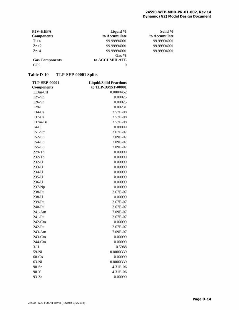
24590-WTP-MDD-PR-01-002, Rev 14 Dynamic (G2) Model Design Document
Page D-14
24590-PADC-F00041 Rev 8 (Revised 3/5/2018)
PJV-HEPA
Components
Liquid %
to Accumulate
Solid %
to Accumulate
Ti+4 99.99994001 99.99994001
Zn+2 99.99994001 99.99994001
Zr+4 99.99994001 99.99994001
Gas Components
Gas %
to ACCUMULATE
CO2 0
Table D-10 TLP-SEP-00001 Splits
TLP-SEP-00001
Components
Liquid/Solid Fractions
to TLP-DMST-00001
113m-Cd 0.0000452
125-Sb 0.00025
126-Sn 0.00025
129-I 0.00231
134-Cs 3.57E-08
137-Cs 3.57E-08
137m-Ba 3.57E-08
14-C 0.00099
151-Sm 2.67E-07
152-Eu 7.09E-07
154-Eu 7.09E-07
155-Eu 7.09E-07
229-Th 0.00099
232-Th 0.00099
232-U 0.00099
233-U 0.00099
234-U 0.00099
235-U 0.00099
236-U 0.00099
237-Np 0.00099
238-Pu 2.67E-07
238-U 0.00099
239-Pu 2.67E-07
240-Pu 2.67E-07
241-Am 7.09E-07
241-Pu 2.67E-07
242-Cm 0.00099
242-Pu 2.67E-07
243-Am 7.09E-07
243-Cm 0.00099
244-Cm 0.00099
3-H 0.5988
59-Ni 0.0000339
60-Co 0.00099
63-Ni 0.0000339
90-Sr 4.31E-06
90-Y 4.31E-06
93-Zr 0.00099
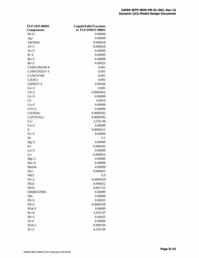
24590-WTP-MDD-PR-01-002, Rev 14 Dynamic (G2) Model Design Document
Page D-15
24590-PADC-F00041 Rev 8 (Revised 3/5/2018)
TLP-SEP-00001
Components
Liquid/Solid Fractions
to TLP-DMST-00001
99-Tc 0.00099
Ag+ 0.00099
Al(OH)4- 0.000658
Al+3 0.000658
As+5 0.00099
B+3 0.00099
Ba+2 0.00099
Bi+3 0.00025
C10H12N2O8-4 0.001
C10H15N2O7-3 0.001
C12H27O4P 0.001
C2O4-2 0.001
C6H5O7-3 0.09346
Ca+2 0.001
Cd+2 0.0000452
Ce+3 0.00099
Cl- 0.0019
Co+3 0.00099
CO3-2 0.00099
Cr(OH)4- 0.0000282
Cr(TOTAL) 0.0000282
Cs+ 3.57E-08
Cu+2 0.00099
F- 0.0000411
Fe+3 0.00099
H+ 0.1
Hg+2 0.00099
K+ 0.000282
La+3 0.00099
Li+ 0.000033
Mg+2 0.00099
Mn+4 0.00099
MnO4- 0.00099
Na+ 0.000033
NH3 0.9
Ni+2 0.0000339
NO2- 0.000412
NO3- 0.001733
OH(BOUND) 0.00099
OH- 0.00099
Pb+2 0.00025
Pd+2 0.0000339
PO4-3 0.00099
Pu+4 2.67E-07
Sb+5 0.00025
Si+4 0.00099
SO4-2 0.000704
Sr+2 4.31E-06
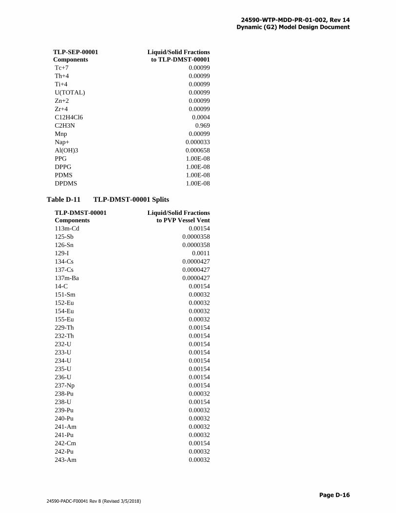
24590-WTP-MDD-PR-01-002, Rev 14 Dynamic (G2) Model Design Document
Page D-16
24590-PADC-F00041 Rev 8 (Revised 3/5/2018)
TLP-SEP-00001
Components
Liquid/Solid Fractions
to TLP-DMST-00001
Tc+7 0.00099
Th+4 0.00099
Ti+4 0.00099
U(TOTAL) 0.00099
Zn+2 0.00099
Zr+4 0.00099
C12H4Cl6 0.0004
C2H3N 0.969
Mnp 0.00099
Nap+ 0.000033
Al(OH)3 0.000658
PPG 1.00E-08
DPPG 1.00E-08
PDMS 1.00E-08
DPDMS 1.00E-08
Table D-11 TLP-DMST-00001 Splits
TLP-DMST-00001
Components
Liquid/Solid Fractions
to PVP Vessel Vent
113m-Cd 0.00154
125-Sb 0.0000358
126-Sn 0.0000358
129-I 0.0011
134-Cs 0.0000427
137-Cs 0.0000427
137m-Ba 0.0000427
14-C 0.00154
151-Sm 0.00032
152-Eu 0.00032
154-Eu 0.00032
155-Eu 0.00032
229-Th 0.00154
232-Th 0.00154
232-U 0.00154
233-U 0.00154
234-U 0.00154
235-U 0.00154
236-U 0.00154
237-Np 0.00154
238-Pu 0.00032
238-U 0.00154
239-Pu 0.00032
240-Pu 0.00032
241-Am 0.00032
241-Pu 0.00032
242-Cm 0.00154
242-Pu 0.00032
243-Am 0.00032
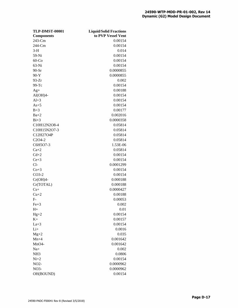
24590-WTP-MDD-PR-01-002, Rev 14 Dynamic (G2) Model Design Document
Page D-17
24590-PADC-F00041 Rev 8 (Revised 3/5/2018)
TLP-DMST-00001
Components
Liquid/Solid Fractions
to PVP Vessel Vent
243-Cm 0.00154
244-Cm 0.00154
3-H 0.014
59-Ni 0.00154
60-Co 0.00154
63-Ni 0.00154
90-Sr 0.0000855
90-Y 0.0000855
93-Zr 0.002
99-Tc 0.00154
Ag+ 0.00188
Al(OH)4- 0.00154
Al+3 0.00154
As+5 0.00154
B+3 0.00177
Ba+2 0.002016
Bi+3 0.0000358
C10H12N2O8-4 0.05814
C10H15N2O7-3 0.05814
C12H27O4P 0.05814
C2O4-2 0.05814
C6H5O7-3 1.53E-06
Ca+2 0.05814
Cd+2 0.00154
Ce+3 0.00154
Cl- 0.0001299
Co+3 0.00154
CO3-2 0.00154
Cr(OH)4- 0.000188
Cr(TOTAL) 0.000188
Cs+ 0.0000427
Cu+2 0.00188
F- 0.00053
Fe+3 0.002
H+ 0.01
Hg+2 0.00154
K+ 0.00157
La+3 0.00154
Li+ 0.0016
Mg+2 0.035
Mn+4 0.001642
MnO4- 0.001642
Na+ 0.002
NH3 0.0806
Ni+2 0.00154
NO2- 0.0000962
NO3- 0.0000962
OH(BOUND) 0.00154
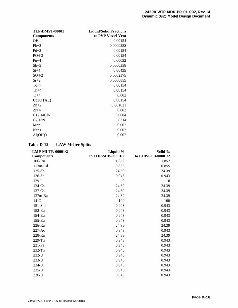
24590-WTP-MDD-PR-01-002, Rev 14 Dynamic (G2) Model Design Document
Page D-18
24590-PADC-F00041 Rev 8 (Revised 3/5/2018)
TLP-DMST-00001
Components
Liquid/Solid Fractions
to PVP Vessel Vent
OH- 0.00154
Pb+2 0.0000358
Pd+2 0.00154
PO4-3 0.00154
Pu+4 0.00032
Sb+5 0.0000358
Si+4 0.00435
SO4-2 0.0002375
Sr+2 0.0000855
Tc+7 0.00154
Th+4 0.00154
Ti+4 0.002
U(TOTAL) 0.00154
Zn+2 0.001621
Zr+4 0.002
C12H4Cl6 0.0004
C2H3N 0.8314
Mnp 0.002
Nap+ 0.002
Al(OH)3 0.002
Table D-12 LAW Melter Splits
LMP-MLTR-00001/2
Components
Liquid %
to LOP-SCB-00001/2
Solid %
to LOP-SCB-00001/2
106-Ru 1.852 1.852
113m-Cd 0.855 0.855
125-Sb 24.39 24.39
126-Sn 0.943 0.943
129-I 0 0
134-Cs 24.39 24.39
137-Cs 24.39 24.39
137m-Ba 24.39 24.39
14-C 100 100
151-Sm 0.943 0.943
152-Eu 0.943 0.943
154-Eu 0.943 0.943
155-Eu 0.943 0.943
226-Ra 24.39 24.39
227-Ac 0.943 0.943
228-Ra 24.39 24.39
229-Th 0.943 0.943
231-Pa 0.943 0.943
232-Th 0.943 0.943
232-U 0.943 0.943
233-U 0.943 0.943
234-U 0.943 0.943
235-U 0.943 0.943
236-U 0.943 0.943
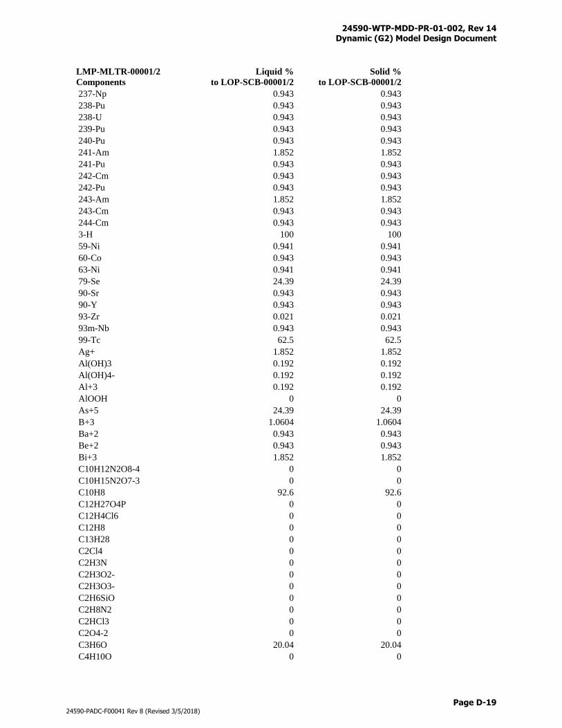
24590-WTP-MDD-PR-01-002, Rev 14 Dynamic (G2) Model Design Document
Page D-19
24590-PADC-F00041 Rev 8 (Revised 3/5/2018)
LMP-MLTR-00001/2
Components
Liquid %
to LOP-SCB-00001/2
Solid %
to LOP-SCB-00001/2
237-Np 0.943 0.943
238-Pu 0.943 0.943
238-U 0.943 0.943
239-Pu 0.943 0.943
240-Pu 0.943 0.943
241-Am 1.852 1.852
241-Pu 0.943 0.943
242-Cm 0.943 0.943
242-Pu 0.943 0.943
243-Am 1.852 1.852
243-Cm 0.943 0.943
244-Cm 0.943 0.943
3-H 100 100
59-Ni 0.941 0.941
60-Co 0.943 0.943
63-Ni 0.941 0.941
79-Se 24.39 24.39
90-Sr 0.943 0.943
90-Y 0.943 0.943
93-Zr 0.021 0.021
93m-Nb 0.943 0.943
99-Tc 62.5 62.5
Ag+ 1.852 1.852
Al(OH)3 0.192 0.192
Al(OH)4- 0.192 0.192
Al+3 0.192 0.192
AlOOH 0 0
As+5 24.39 24.39
B+3 1.0604 1.0604
Ba+2 0.943 0.943
Be+2 0.943 0.943
Bi+3 1.852 1.852
C10H12N2O8-4 0 0
C10H15N2O7-3 0 0
C10H8 92.6 92.6
C12H27O4P 0 0
C12H4Cl6 0 0
C12H8 0 0
C13H28 0 0
C2Cl4 0 0
C2H3N 0 0
C2H3O2- 0 0
C2H3O3- 0 0
C2H6SiO 0 0
C2H8N2 0 0
C2HCl3 0 0
C2O4-2 0 0
C3H6O 20.04 20.04
C4H10O 0 0
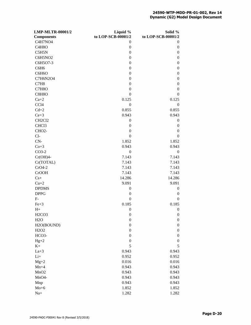
24590-WTP-MDD-PR-01-002, Rev 14 Dynamic (G2) Model Design Document
Page D-20
24590-PADC-F00041 Rev 8 (Revised 3/5/2018)
LMP-MLTR-00001/2
Components
Liquid %
to LOP-SCB-00001/2
Solid %
to LOP-SCB-00001/2
C4H7NO4 0 0
C4H8O 0 0
C5H5N 0 0
C6H5NO2 0 0
C6H5O7-3 0 0
C6H6 0 0
C6H6O 0 0
C7H6N2O4 0 0
C7H8 0 0
C7H8O 0 0
C8H8O 0 0
Ca+2 0.125 0.125
CCl4 0 0
Cd+2 0.855 0.855
Ce+3 0.943 0.943
CH2Cl2 0 0
CHCl3 0 0
CHO2- 0 0
Cl- 0 0
CN- 1.852 1.852
Co+3 0.943 0.943
CO3-2 0 0
Cr(OH)4- 7.143 7.143
Cr(TOTAL) 7.143 7.143
CrO4-2 7.143 7.143
CrOOH 7.143 7.143
Cs+ 14.286 14.286
Cu+2 9.091 9.091
DPDMS 0 0
DPPG 0 0
F- 0 0
Fe+3 0.185 0.185
H+ 0 0
H2CO3 0 0
H2O 0 0
H2O(BOUND) 0 0
H2O2 0 0
HCO3- 0 0
Hg+2 0 0
K+ 5 5
La+3 0.943 0.943
Li+ 0.952 0.952
Mg+2 0.016 0.016
Mn+4 0.943 0.943
MnO2 0.943 0.943
MnO4- 0.943 0.943
Mnp 0.943 0.943
Mo+6 1.852 1.852
Na+ 1.282 1.282
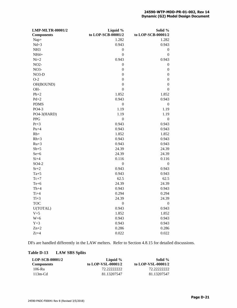
24590-WTP-MDD-PR-01-002, Rev 14 Dynamic (G2) Model Design Document
Page D-21
24590-PADC-F00041 Rev 8 (Revised 3/5/2018)
LMP-MLTR-00001/2
Components
Liquid %
to LOP-SCB-00001/2
Solid %
to LOP-SCB-00001/2
Nap+ 1.282 1.282
Nd+3 0.943 0.943
NH3 0 0
NH4+ 0 0
Ni+2 0.943 0.943
NO2- 0 0
NO3- 0 0
NO3-D 0 0
O-2 0 0
OH(BOUND) 0 0
OH- 0 0
Pb+2 1.852 1.852
Pd+2 0.943 0.943
PDMS 0 0
PO4-3 1.19 1.19
PO4-3(HARD) 1.19 1.19
PPG 0 0
Pr+3 0.943 0.943
Pu+4 0.943 0.943
Rb+ 1.852 1.852
Rh+3 0.943 0.943
Ru+3 0.943 0.943
Sb+5 24.39 24.39
Se+6 24.39 24.39
Si+4 0.116 0.116
SO4-2 0 0
Sr+2 0.943 0.943
Ta+5 0.943 0.943
Tc+7 62.5 62.5
Te+6 24.39 24.39
Th+4 0.943 0.943
Ti+4 0.294 0.294
Tl+3 24.39 24.39
TOC 0 0
U(TOTAL) 0.943 0.943
V+5 1.852 1.852
W+6 0.943 0.943
Y+3 0.943 0.943
Zn+2 0.286 0.286
Zr+4 0.022 0.022
DFs are handled differently in the LAW melters. Refer to Section 4.8.15 for detailed discussions.
Table D-13 LAW SBS Splits
LOP-SCB-00001/2
Components
Liquid %
to LOP-VSL-00001/2
Solid %
to LOP-VSL-00001/2
106-Ru 72.22222222 72.22222222
113m-Cd 81.13207547 81.13207547
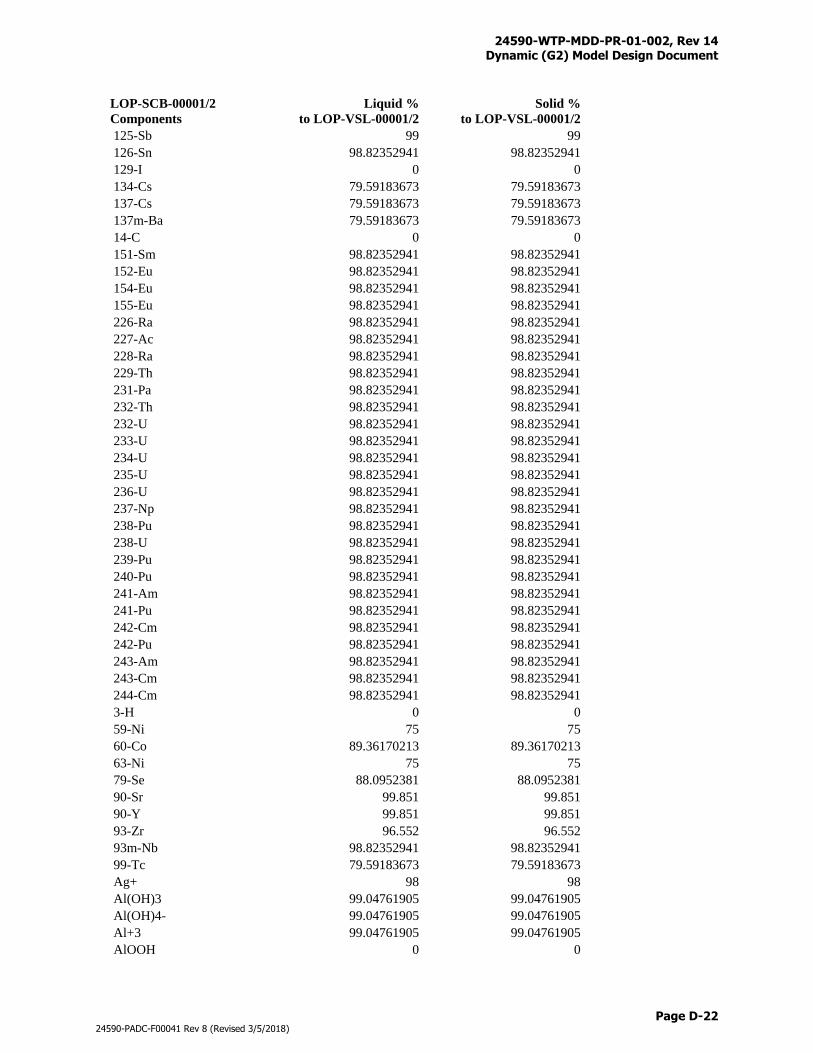
24590-WTP-MDD-PR-01-002, Rev 14 Dynamic (G2) Model Design Document
Page D-22
24590-PADC-F00041 Rev 8 (Revised 3/5/2018)
LOP-SCB-00001/2
Components
Liquid %
to LOP-VSL-00001/2
Solid %
to LOP-VSL-00001/2
125-Sb 99 99
126-Sn 98.82352941 98.82352941
129-I 0 0
134-Cs 79.59183673 79.59183673
137-Cs 79.59183673 79.59183673
137m-Ba 79.59183673 79.59183673
14-C 0 0
151-Sm 98.82352941 98.82352941
152-Eu 98.82352941 98.82352941
154-Eu 98.82352941 98.82352941
155-Eu 98.82352941 98.82352941
226-Ra 98.82352941 98.82352941
227-Ac 98.82352941 98.82352941
228-Ra 98.82352941 98.82352941
229-Th 98.82352941 98.82352941
231-Pa 98.82352941 98.82352941
232-Th 98.82352941 98.82352941
232-U 98.82352941 98.82352941
233-U 98.82352941 98.82352941
234-U 98.82352941 98.82352941
235-U 98.82352941 98.82352941
236-U 98.82352941 98.82352941
237-Np 98.82352941 98.82352941
238-Pu 98.82352941 98.82352941
238-U 98.82352941 98.82352941
239-Pu 98.82352941 98.82352941
240-Pu 98.82352941 98.82352941
241-Am 98.82352941 98.82352941
241-Pu 98.82352941 98.82352941
242-Cm 98.82352941 98.82352941
242-Pu 98.82352941 98.82352941
243-Am 98.82352941 98.82352941
243-Cm 98.82352941 98.82352941
244-Cm 98.82352941 98.82352941
3-H 0 0
59-Ni 75 75
60-Co 89.36170213 89.36170213
63-Ni 75 75
79-Se 88.0952381 88.0952381
90-Sr 99.851 99.851
90-Y 99.851 99.851
93-Zr 96.552 96.552
93m-Nb 98.82352941 98.82352941
99-Tc 79.59183673 79.59183673
Ag+ 98 98
Al(OH)3 99.04761905 99.04761905
Al(OH)4- 99.04761905 99.04761905
Al+3 99.04761905 99.04761905
AlOOH 0 0
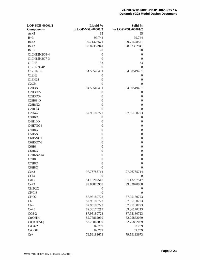
24590-WTP-MDD-PR-01-002, Rev 14 Dynamic (G2) Model Design Document
Page D-23
24590-PADC-F00041 Rev 8 (Revised 3/5/2018)
LOP-SCB-00001/2
Components
Liquid %
to LOP-VSL-00001/2
Solid %
to LOP-VSL-00001/2
As+5 95 95
B+3 99.744 99.744
Ba+2 99.71428571 99.71428571
Be+2 98.82352941 98.82352941
Bi+3 98 98
C10H12N2O8-4 0 0
C10H15N2O7-3 0 0
C10H8 33 33
C12H27O4P 0 0
C12H4Cl6 94.50549451 94.50549451
C12H8 0 0
C13H28 0 0
C2Cl4 0 0
C2H3N 94.50549451 94.50549451
C2H3O2- 0 0
C2H3O3- 0 0
C2H6SiO 0 0
C2H8N2 0 0
C2HCl3 0 0
C2O4-2 87.95180723 87.95180723
C3H6O 0 0
C4H10O 0 0
C4H7NO4 0 0
C4H8O 0 0
C5H5N 0 0
C6H5NO2 0 0
C6H5O7-3 0 0
C6H6 0 0
C6H6O 0 0
C7H6N2O4 0 0
C7H8 0 0
C7H8O 0 0
C8H8O 0 0
Ca+2 97.76785714 97.76785714
CCl4 0 0
Cd+2 81.13207547 81.13207547
Ce+3 99.83870968 99.83870968
CH2Cl2 0 0
CHCl3 0 0
CHO2- 87.95180723 87.95180723
Cl- 87.95180723 87.95180723
CN- 87.95180723 87.95180723
Co+3 89.36170213 89.36170213
CO3-2 87.95180723 87.95180723
Cr(OH)4- 82.75862069 82.75862069
Cr(TOTAL) 82.75862069 82.75862069
CrO4-2 82.759 82.759
CrOOH 82.759 82.759
Cs+ 79.59183673 79.59183673
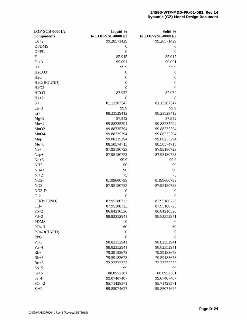
24590-WTP-MDD-PR-01-002, Rev 14 Dynamic (G2) Model Design Document
Page D-24
24590-PADC-F00041 Rev 8 (Revised 3/5/2018)
LOP-SCB-00001/2
Components
Liquid %
to LOP-VSL-00001/2
Solid %
to LOP-VSL-00001/2
Cu+2 99.28571429 99.28571429
DPDMS 0 0
DPPG 0 0
F- 85.915 85.915
Fe+3 99.091 99.091
H+ 99.9 99.9
H2CO3 0 0
H2O 0 0
H2O(BOUND) 0 0
H2O2 0 0
HCO3- 87.952 87.952
Hg+2 0 0
K+ 81.13207547 81.13207547
La+3 99.9 99.9
Li+ 88.23529412 88.23529412
Mg+2 87.342 87.342
Mn+4 99.88235294 99.88235294
MnO2 99.88235294 99.88235294
MnO4- 99.88235294 99.88235294
Mnp 99.88235294 99.88235294
Mo+6 88.50574713 88.50574713
Na+ 87.95180723 87.95180723
Nap+ 87.95180723 87.95180723
Nd+3 99.9 99.9
NH3 90 90
NH4+ 90 90
Ni+2 75 75
NO2- 0.199600798 0.199600798
NO3- 87.95180723 87.95180723
NO3-D 0 0
O-2 0 0
OH(BOUND) 87.95180723 87.95180723
OH- 87.95180723 87.95180723
Pb+2 86.84210526 86.84210526
Pd+2 98.82352941 98.82352941
PDMS 0 0
PO4-3 60 60
PO4-3(HARD) 0 0
PPG 0 0
Pr+3 98.82352941 98.82352941
Pu+4 98.82352941 98.82352941
Rb+ 79.59183673 79.59183673
Rh+3 79.59183673 79.59183673
Ru+3 72.22222222 72.22222222
Sb+5 99 99
Se+6 88.0952381 88.0952381
Si+4 99.07407407 99.07407407
SO4-2 85.71428571 85.71428571
Sr+2 99.85074627 99.85074627
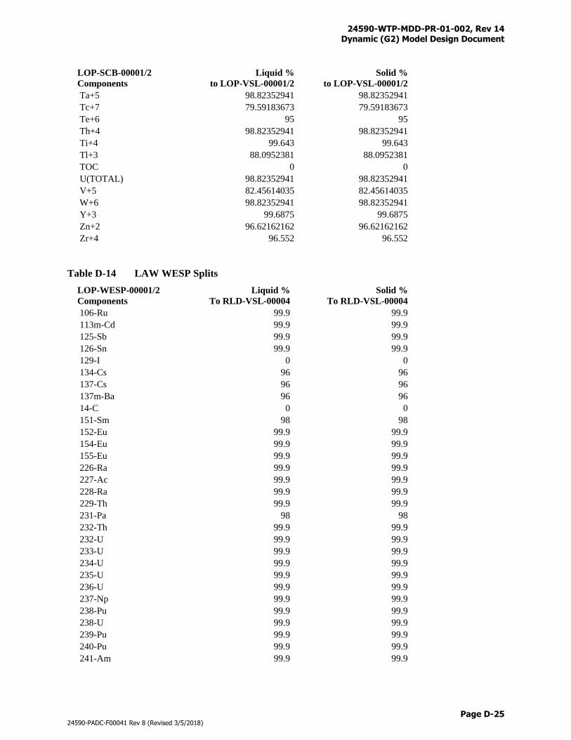
24590-WTP-MDD-PR-01-002, Rev 14 Dynamic (G2) Model Design Document
Page D-25
24590-PADC-F00041 Rev 8 (Revised 3/5/2018)
LOP-SCB-00001/2
Components
Liquid %
to LOP-VSL-00001/2
Solid %
to LOP-VSL-00001/2
Ta+5 98.82352941 98.82352941
Tc+7 79.59183673 79.59183673
Te+6 95 95
Th+4 98.82352941 98.82352941
Ti+4 99.643 99.643
Tl+3 88.0952381 88.0952381
TOC 0 0
U(TOTAL) 98.82352941 98.82352941
V+5 82.45614035 82.45614035
W+6 98.82352941 98.82352941
Y+3 99.6875 99.6875
Zn+2 96.62162162 96.62162162
Zr+4 96.552 96.552
Table D-14 LAW WESP Splits
LOP-WESP-00001/2
Components
Liquid %
To RLD-VSL-00004
Solid %
To RLD-VSL-00004
106-Ru 99.9 99.9
113m-Cd 99.9 99.9
125-Sb 99.9 99.9
126-Sn 99.9 99.9
129-I 0 0
134-Cs 96 96
137-Cs 96 96
137m-Ba 96 96
14-C 0 0
151-Sm 98 98
152-Eu 99.9 99.9
154-Eu 99.9 99.9
155-Eu 99.9 99.9
226-Ra 99.9 99.9
227-Ac 99.9 99.9
228-Ra 99.9 99.9
229-Th 99.9 99.9
231-Pa 98 98
232-Th 99.9 99.9
232-U 99.9 99.9
233-U 99.9 99.9
234-U 99.9 99.9
235-U 99.9 99.9
236-U 99.9 99.9
237-Np 99.9 99.9
238-Pu 99.9 99.9
238-U 99.9 99.9
239-Pu 99.9 99.9
240-Pu 99.9 99.9
241-Am 99.9 99.9
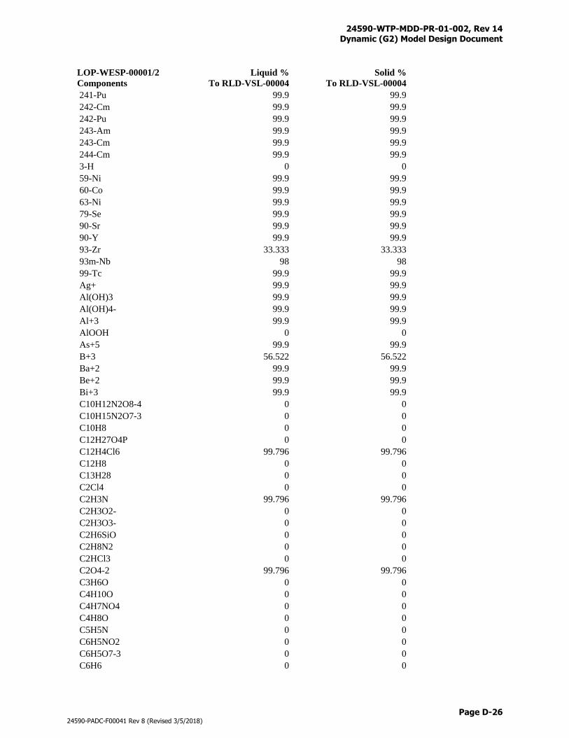
24590-WTP-MDD-PR-01-002, Rev 14 Dynamic (G2) Model Design Document
Page D-26
24590-PADC-F00041 Rev 8 (Revised 3/5/2018)
LOP-WESP-00001/2
Components
Liquid %
To RLD-VSL-00004
Solid %
To RLD-VSL-00004
241-Pu 99.9 99.9
242-Cm 99.9 99.9
242-Pu 99.9 99.9
243-Am 99.9 99.9
243-Cm 99.9 99.9
244-Cm 99.9 99.9
3-H 0 0
59-Ni 99.9 99.9
60-Co 99.9 99.9
63-Ni 99.9 99.9
79-Se 99.9 99.9
90-Sr 99.9 99.9
90-Y 99.9 99.9
93-Zr 33.333 33.333
93m-Nb 98 98
99-Tc 99.9 99.9
Ag+ 99.9 99.9
Al(OH)3 99.9 99.9
Al(OH)4- 99.9 99.9
Al+3 99.9 99.9
AlOOH 0 0
As+5 99.9 99.9
B+3 56.522 56.522
Ba+2 99.9 99.9
Be+2 99.9 99.9
Bi+3 99.9 99.9
C10H12N2O8-4 0 0
C10H15N2O7-3 0 0
C10H8 0 0
C12H27O4P 0 0
C12H4Cl6 99.796 99.796
C12H8 0 0
C13H28 0 0
C2Cl4 0 0
C2H3N 99.796 99.796
C2H3O2- 0 0
C2H3O3- 0 0
C2H6SiO 0 0
C2H8N2 0 0
C2HCl3 0 0
C2O4-2 99.796 99.796
C3H6O 0 0
C4H10O 0 0
C4H7NO4 0 0
C4H8O 0 0
C5H5N 0 0
C6H5NO2 0 0
C6H5O7-3 0 0
C6H6 0 0
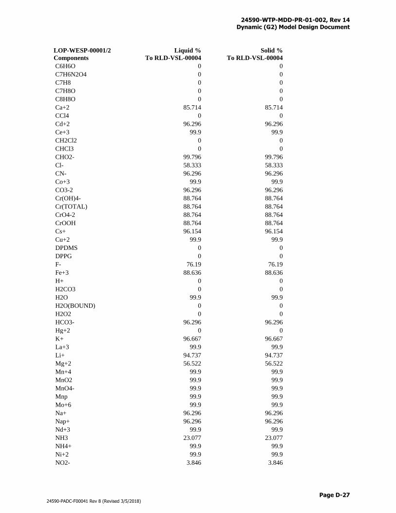
24590-WTP-MDD-PR-01-002, Rev 14 Dynamic (G2) Model Design Document
Page D-27
24590-PADC-F00041 Rev 8 (Revised 3/5/2018)
LOP-WESP-00001/2
Components
Liquid %
To RLD-VSL-00004
Solid %
To RLD-VSL-00004
C6H6O 0 0
C7H6N2O4 0 0
C7H8 0 0
C7H8O 0 0
C8H8O 0 0
Ca+2 85.714 85.714
CCl4 0 0
Cd+2 96.296 96.296
Ce+3 99.9 99.9
CH2Cl2 0 0
CHCl3 0 0
CHO2- 99.796 99.796
Cl- 58.333 58.333
CN- 96.296 96.296
Co+3 99.9 99.9
CO3-2 96.296 96.296
Cr(OH)4- 88.764 88.764
Cr(TOTAL) 88.764 88.764
CrO4-2 88.764 88.764
CrOOH 88.764 88.764
Cs+ 96.154 96.154
Cu+2 99.9 99.9
DPDMS 0 0
DPPG 0 0
F- 76.19 76.19
Fe+3 88.636 88.636
H+ 0 0
H2CO3 0 0
H2O 99.9 99.9
H2O(BOUND) 0 0
H2O2 0 0
HCO3- 96.296 96.296
Hg+2 0 0
K+ 96.667 96.667
La+3 99.9 99.9
Li+ 94.737 94.737
Mg+2 56.522 56.522
Mn+4 99.9 99.9
MnO2 99.9 99.9
MnO4- 99.9 99.9
Mnp 99.9 99.9
Mo+6 99.9 99.9
Na+ 96.296 96.296
Nap+ 96.296 96.296
Nd+3 99.9 99.9
NH3 23.077 23.077
NH4+ 99.9 99.9
Ni+2 99.9 99.9
NO2- 3.846 3.846
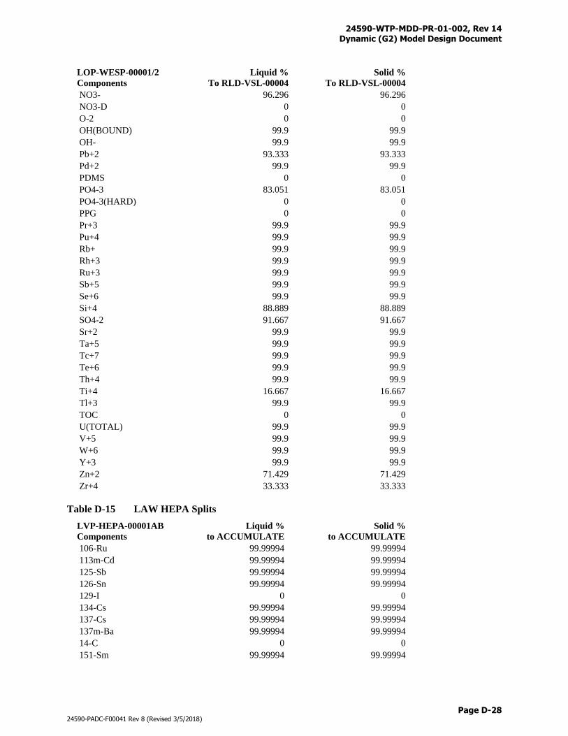
24590-WTP-MDD-PR-01-002, Rev 14 Dynamic (G2) Model Design Document
Page D-28
24590-PADC-F00041 Rev 8 (Revised 3/5/2018)
LOP-WESP-00001/2
Components
Liquid %
To RLD-VSL-00004
Solid %
To RLD-VSL-00004
NO3- 96.296 96.296
NO3-D 0 0
O-2 0 0
OH(BOUND) 99.9 99.9
OH- 99.9 99.9
Pb+2 93.333 93.333
Pd+2 99.9 99.9
PDMS 0 0
PO4-3 83.051 83.051
PO4-3(HARD) 0 0
PPG 0 0
Pr+3 99.9 99.9
Pu+4 99.9 99.9
Rb+ 99.9 99.9
Rh+3 99.9 99.9
Ru+3 99.9 99.9
Sb+5 99.9 99.9
Se+6 99.9 99.9
Si+4 88.889 88.889
SO4-2 91.667 91.667
Sr+2 99.9 99.9
Ta+5 99.9 99.9
Tc+7 99.9 99.9
Te+6 99.9 99.9
Th+4 99.9 99.9
Ti+4 16.667 16.667
Tl+3 99.9 99.9
TOC 0 0
U(TOTAL) 99.9 99.9
V+5 99.9 99.9
W+6 99.9 99.9
Y+3 99.9 99.9
Zn+2 71.429 71.429
Zr+4 33.333 33.333
Table D-15 LAW HEPA Splits
LVP-HEPA-00001AB
Components
Liquid %
to ACCUMULATE
Solid %
to ACCUMULATE
106-Ru 99.99994 99.99994
113m-Cd 99.99994 99.99994
125-Sb 99.99994 99.99994
126-Sn 99.99994 99.99994
129-I 0 0
134-Cs 99.99994 99.99994
137-Cs 99.99994 99.99994
137m-Ba 99.99994 99.99994
14-C 0 0
151-Sm 99.99994 99.99994
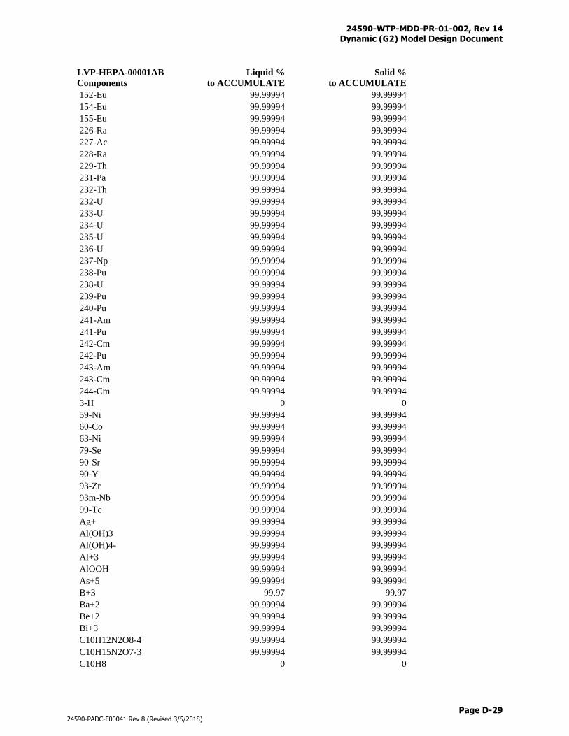
24590-WTP-MDD-PR-01-002, Rev 14 Dynamic (G2) Model Design Document
Page D-29
24590-PADC-F00041 Rev 8 (Revised 3/5/2018)
LVP-HEPA-00001AB
Components
Liquid %
to ACCUMULATE
Solid %
to ACCUMULATE
152-Eu 99.99994 99.99994
154-Eu 99.99994 99.99994
155-Eu 99.99994 99.99994
226-Ra 99.99994 99.99994
227-Ac 99.99994 99.99994
228-Ra 99.99994 99.99994
229-Th 99.99994 99.99994
231-Pa 99.99994 99.99994
232-Th 99.99994 99.99994
232-U 99.99994 99.99994
233-U 99.99994 99.99994
234-U 99.99994 99.99994
235-U 99.99994 99.99994
236-U 99.99994 99.99994
237-Np 99.99994 99.99994
238-Pu 99.99994 99.99994
238-U 99.99994 99.99994
239-Pu 99.99994 99.99994
240-Pu 99.99994 99.99994
241-Am 99.99994 99.99994
241-Pu 99.99994 99.99994
242-Cm 99.99994 99.99994
242-Pu 99.99994 99.99994
243-Am 99.99994 99.99994
243-Cm 99.99994 99.99994
244-Cm 99.99994 99.99994
3-H 0 0
59-Ni 99.99994 99.99994
60-Co 99.99994 99.99994
63-Ni 99.99994 99.99994
79-Se 99.99994 99.99994
90-Sr 99.99994 99.99994
90-Y 99.99994 99.99994
93-Zr 99.99994 99.99994
93m-Nb 99.99994 99.99994
99-Tc 99.99994 99.99994
Ag+ 99.99994 99.99994
Al(OH)3 99.99994 99.99994
Al(OH)4- 99.99994 99.99994
Al+3 99.99994 99.99994
AlOOH 99.99994 99.99994
As+5 99.99994 99.99994
B+3 99.97 99.97
Ba+2 99.99994 99.99994
Be+2 99.99994 99.99994
Bi+3 99.99994 99.99994
C10H12N2O8-4 99.99994 99.99994
C10H15N2O7-3 99.99994 99.99994
C10H8 0 0
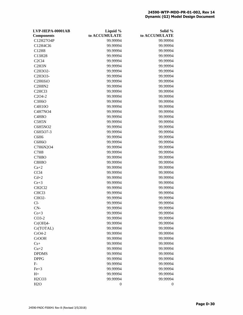
24590-WTP-MDD-PR-01-002, Rev 14 Dynamic (G2) Model Design Document
Page D-30
24590-PADC-F00041 Rev 8 (Revised 3/5/2018)
LVP-HEPA-00001AB
Components
Liquid %
to ACCUMULATE
Solid %
to ACCUMULATE
C12H27O4P 99.99994 99.99994
C12H4Cl6 99.99994 99.99994
C12H8 99.99994 99.99994
C13H28 99.99994 99.99994
C2Cl4 99.99994 99.99994
C2H3N 99.99994 99.99994
C2H3O2- 99.99994 99.99994
C2H3O3- 99.99994 99.99994
C2H6SiO 99.99994 99.99994
C2H8N2 99.99994 99.99994
C2HCl3 99.99994 99.99994
C2O4-2 99.99994 99.99994
C3H6O 99.99994 99.99994
C4H10O 99.99994 99.99994
C4H7NO4 99.99994 99.99994
C4H8O 99.99994 99.99994
C5H5N 99.99994 99.99994
C6H5NO2 99.99994 99.99994
C6H5O7-3 99.99994 99.99994
C6H6 99.99994 99.99994
C6H6O 99.99994 99.99994
C7H6N2O4 99.99994 99.99994
C7H8 99.99994 99.99994
C7H8O 99.99994 99.99994
C8H8O 99.99994 99.99994
Ca+2 99.99994 99.99994
CCl4 99.99994 99.99994
Cd+2 99.99994 99.99994
Ce+3 99.99994 99.99994
CH2Cl2 99.99994 99.99994
CHCl3 99.99994 99.99994
CHO2- 99.99994 99.99994
Cl- 99.99994 99.99994
CN- 99.99994 99.99994
Co+3 99.99994 99.99994
CO3-2 99.99994 99.99994
Cr(OH)4- 99.99994 99.99994
Cr(TOTAL) 99.99994 99.99994
CrO4-2 99.99994 99.99994
CrOOH 99.99994 99.99994
Cs+ 99.99994 99.99994
Cu+2 99.99994 99.99994
DPDMS 99.99994 99.99994
DPPG 99.99994 99.99994
F- 99.99994 99.99994
Fe+3 99.99994 99.99994
H+ 99.99994 99.99994
H2CO3 99.99994 99.99994
H2O 0 0
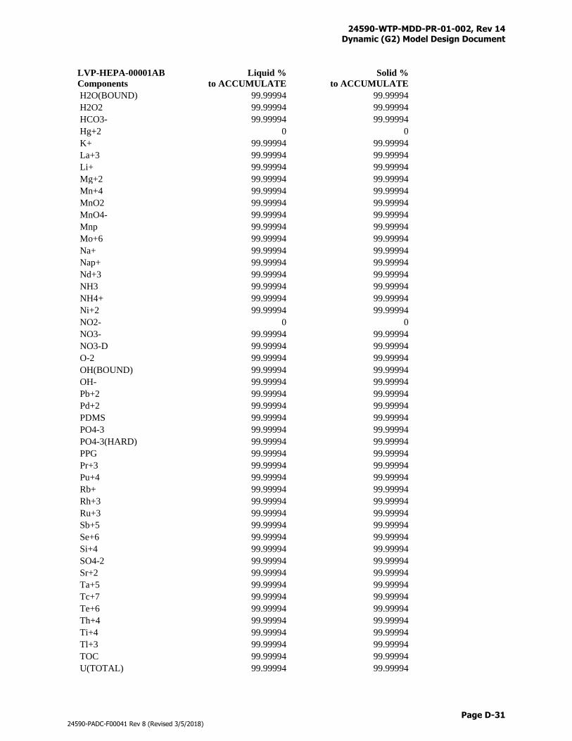
24590-WTP-MDD-PR-01-002, Rev 14 Dynamic (G2) Model Design Document
Page D-31
24590-PADC-F00041 Rev 8 (Revised 3/5/2018)
LVP-HEPA-00001AB
Components
Liquid %
to ACCUMULATE
Solid %
to ACCUMULATE
H2O(BOUND) 99.99994 99.99994
H2O2 99.99994 99.99994
HCO3- 99.99994 99.99994
Hg+2 0 0
K+ 99.99994 99.99994
La+3 99.99994 99.99994
Li+ 99.99994 99.99994
Mg+2 99.99994 99.99994
Mn+4 99.99994 99.99994
MnO2 99.99994 99.99994
MnO4- 99.99994 99.99994
Mnp 99.99994 99.99994
Mo+6 99.99994 99.99994
Na+ 99.99994 99.99994
Nap+ 99.99994 99.99994
Nd+3 99.99994 99.99994
NH3 99.99994 99.99994
NH4+ 99.99994 99.99994
Ni+2 99.99994 99.99994
NO2- 0 0
NO3- 99.99994 99.99994
NO3-D 99.99994 99.99994
O-2 99.99994 99.99994
OH(BOUND) 99.99994 99.99994
OH- 99.99994 99.99994
Pb+2 99.99994 99.99994
Pd+2 99.99994 99.99994
PDMS 99.99994 99.99994
PO4-3 99.99994 99.99994
PO4-3(HARD) 99.99994 99.99994
PPG 99.99994 99.99994
Pr+3 99.99994 99.99994
Pu+4 99.99994 99.99994
Rb+ 99.99994 99.99994
Rh+3 99.99994 99.99994
Ru+3 99.99994 99.99994
Sb+5 99.99994 99.99994
Se+6 99.99994 99.99994
Si+4 99.99994 99.99994
SO4-2 99.99994 99.99994
Sr+2 99.99994 99.99994
Ta+5 99.99994 99.99994
Tc+7 99.99994 99.99994
Te+6 99.99994 99.99994
Th+4 99.99994 99.99994
Ti+4 99.99994 99.99994
Tl+3 99.99994 99.99994
TOC 99.99994 99.99994
U(TOTAL) 99.99994 99.99994

24590-WTP-MDD-PR-01-002, Rev 14 Dynamic (G2) Model Design Document
Page D-32
24590-PADC-F00041 Rev 8 (Revised 3/5/2018)
LVP-HEPA-00001AB
Components
Liquid %
to ACCUMULATE
Solid %
to ACCUMULATE
V+5 99.99994 99.99994
W+6 99.99994 99.99994
Y+3 99.99994 99.99994
Zn+2 99.99994 99.99994
Zr+4 99.99994 99.99994
Gas Components
Gas %
to ACCUMULATE
129-I 0
C12H4Cl6 99.99994
C2H3N 99.99994
CO2 0
H2O 0
HCl 69.512
HF 26.471
Hg 99.99994
N2 0
NH3 99.99994
NO 0
NO2 0
O2 0
P2O5 99.99994
SO2 90
SO3 99.99994
Table D-16 LAW Carbon Absorber Splits
LVP-ADBR-00001A/B
Components
Liquid %
to ACCUMULATE
Solid %
to ACCUMULATE
106-Ru 0 0
113m-Cd 0 0
125-Sb 0 0
126-Sn 0 0
129-I 0 0
134-Cs 0 0
137-Cs 0 0
137m-Ba 0 0
14-C 0 0
151-Sm 0 0
152-Eu 0 0
154-Eu 0 0
155-Eu 0 0
226-Ra 0 0
227-Ac 0 0
228-Ra 0 0
229-Th 0 0
231-Pa 0 0
232-Th 0 0
232-U 0 0
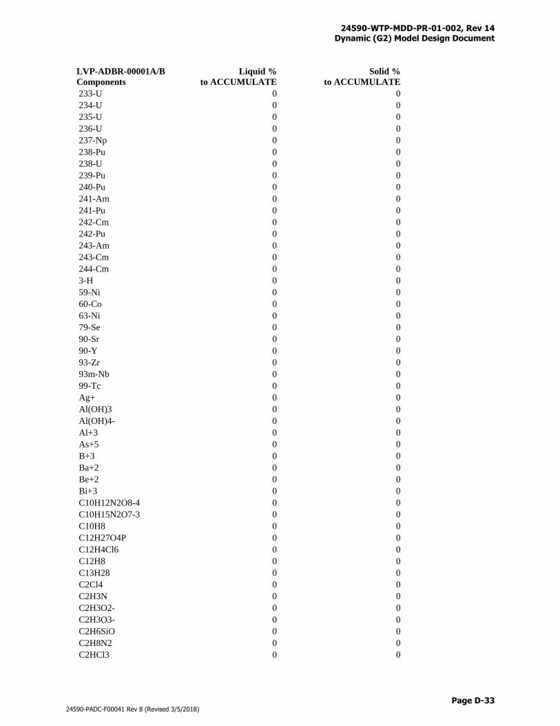
24590-WTP-MDD-PR-01-002, Rev 14 Dynamic (G2) Model Design Document
Page D-33
24590-PADC-F00041 Rev 8 (Revised 3/5/2018)
LVP-ADBR-00001A/B
Components
Liquid %
to ACCUMULATE
Solid %
to ACCUMULATE
233-U 0 0
234-U 0 0
235-U 0 0
236-U 0 0
237-Np 0 0
238-Pu 0 0
238-U 0 0
239-Pu 0 0
240-Pu 0 0
241-Am 0 0
241-Pu 0 0
242-Cm 0 0
242-Pu 0 0
243-Am 0 0
243-Cm 0 0
244-Cm 0 0
3-H 0 0
59-Ni 0 0
60-Co 0 0
63-Ni 0 0
79-Se 0 0
90-Sr 0 0
90-Y 0 0
93-Zr 0 0
93m-Nb 0 0
99-Tc 0 0
Ag+ 0 0
Al(OH)3 0 0
Al(OH)4- 0 0
Al+3 0 0
As+5 0 0
B+3 0 0
Ba+2 0 0
Be+2 0 0
Bi+3 0 0
C10H12N2O8-4 0 0
C10H15N2O7-3 0 0
C10H8 0 0
C12H27O4P 0 0
C12H4Cl6 0 0
C12H8 0 0
C13H28 0 0
C2Cl4 0 0
C2H3N 0 0
C2H3O2- 0 0
C2H3O3- 0 0
C2H6SiO 0 0
C2H8N2 0 0
C2HCl3 0 0
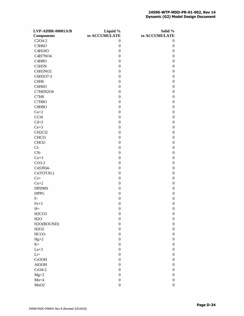
24590-WTP-MDD-PR-01-002, Rev 14 Dynamic (G2) Model Design Document
Page D-34
24590-PADC-F00041 Rev 8 (Revised 3/5/2018)
LVP-ADBR-00001A/B
Components
Liquid %
to ACCUMULATE
Solid %
to ACCUMULATE
C2O4-2 0 0
C3H6O 0 0
C4H10O 0 0
C4H7NO4 0 0
C4H8O 0 0
C5H5N 0 0
C6H5NO2 0 0
C6H5O7-3 0 0
C6H6 0 0
C6H6O 0 0
C7H6N2O4 0 0
C7H8 0 0
C7H8O 0 0
C8H8O 0 0
Ca+2 0 0
CCl4 0 0
Cd+2 0 0
Ce+3 0 0
CH2Cl2 0 0
CHCl3 0 0
CHO2- 0 0
Cl- 0 0
CN- 0 0
Co+3 0 0
CO3-2 0 0
Cr(OH)4- 0 0
Cr(TOTAL) 0 0
Cs+ 0 0
Cu+2 0 0
DPDMS 0 0
DPPG 0 0
F- 0 0
Fe+3 0 0
H+ 0 0
H2CO3 0 0
H2O 0 0
H2O(BOUND) 0 0
H2O2 0 0
HCO3- 0 0
Hg+2 0 0
K+ 0 0
La+3 0 0
Li+ 0 0
CrOOH 0 0
AlOOH 0 0
CrO4-2 0 0
Mg+2 0 0
Mn+4 0 0
MnO2 0 0
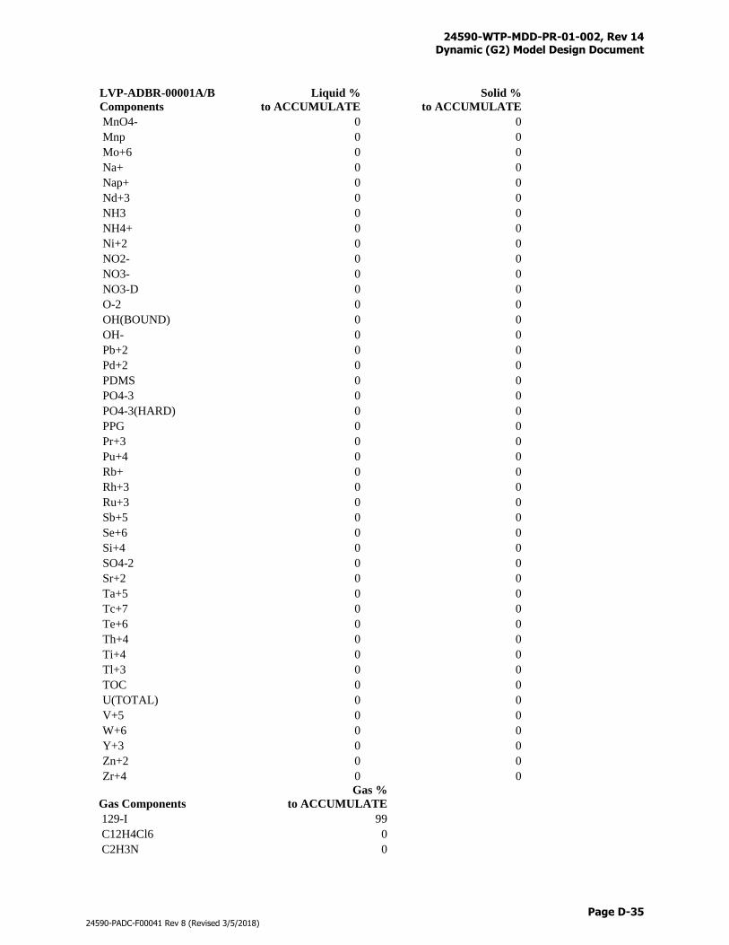
24590-WTP-MDD-PR-01-002, Rev 14 Dynamic (G2) Model Design Document
Page D-35
24590-PADC-F00041 Rev 8 (Revised 3/5/2018)
LVP-ADBR-00001A/B
Components
Liquid %
to ACCUMULATE
Solid %
to ACCUMULATE
MnO4- 0 0
Mnp 0 0
Mo+6 0 0
Na+ 0 0
Nap+ 0 0
Nd+3 0 0
NH3 0 0
NH4+ 0 0
Ni+2 0 0
NO2- 0 0
NO3- 0 0
NO3-D 0 0
O-2 0 0
OH(BOUND) 0 0
OH- 0 0
Pb+2 0 0
Pd+2 0 0
PDMS 0 0
PO4-3 0 0
PO4-3(HARD) 0 0
PPG 0 0
Pr+3 0 0
Pu+4 0 0
Rb+ 0 0
Rh+3 0 0
Ru+3 0 0
Sb+5 0 0
Se+6 0 0
Si+4 0 0
SO4-2 0 0
Sr+2 0 0
Ta+5 0 0
Tc+7 0 0
Te+6 0 0
Th+4 0 0
Ti+4 0 0
Tl+3 0 0
TOC 0 0
U(TOTAL) 0 0
V+5 0 0
W+6 0 0
Y+3 0 0
Zn+2 0 0
Zr+4 0 0
Gas Components
Gas %
to ACCUMULATE
129-I 99
C12H4Cl6 0
C2H3N 0
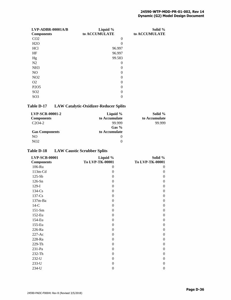
24590-WTP-MDD-PR-01-002, Rev 14 Dynamic (G2) Model Design Document
Page D-36
24590-PADC-F00041 Rev 8 (Revised 3/5/2018)
LVP-ADBR-00001A/B
Components
Liquid %
to ACCUMULATE
Solid %
to ACCUMULATE
CO2 0
H2O 0
HCl 96.997
HF 96.997
Hg 99.583
N2 0
NH3 0
NO 0
NO2 0
O2 0
P2O5 0
SO2 0
SO3 0
Table D-17 LAW Catalytic-Oxidizer-Reducer Splits
LVP-SCR-00001-2
Components
Liquid %
to Accumulate
Solid %
to Accumulate
C2O4-2 99.999 99.999
Gas Components
Gas %
to Accumulate
NO 0
NO2 0
Table D-18 LAW Caustic Scrubber Splits
LVP-SCB-00001
Components
Liquid %
To LVP-TK-00001
Solid %
To LVP-TK-00001
106-Ru 0 0
113m-Cd 0 0
125-Sb 0 0
126-Sn 0 0
129-I 0 0
134-Cs 0 0
137-Cs 0 0
137m-Ba 0 0
14-C 0 0
151-Sm 0 0
152-Eu 0 0
154-Eu 0 0
155-Eu 0 0
226-Ra 0 0
227-Ac 0 0
228-Ra 0 0
229-Th 0 0
231-Pa 0 0
232-Th 0 0
232-U 0 0
233-U 0 0
234-U 0 0
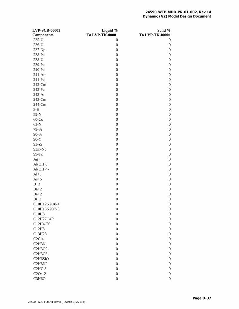
24590-WTP-MDD-PR-01-002, Rev 14 Dynamic (G2) Model Design Document
Page D-37
24590-PADC-F00041 Rev 8 (Revised 3/5/2018)
LVP-SCB-00001
Components
Liquid %
To LVP-TK-00001
Solid %
To LVP-TK-00001
235-U 0 0
236-U 0 0
237-Np 0 0
238-Pu 0 0
238-U 0 0
239-Pu 0 0
240-Pu 0 0
241-Am 0 0
241-Pu 0 0
242-Cm 0 0
242-Pu 0 0
243-Am 0 0
243-Cm 0 0
244-Cm 0 0
3-H 0 0
59-Ni 0 0
60-Co 0 0
63-Ni 0 0
79-Se 0 0
90-Sr 0 0
90-Y 0 0
93-Zr 0 0
93m-Nb 0 0
99-Tc 0 0
Ag+ 0 0
Al(OH)3 0 0
Al(OH)4- 0 0
Al+3 0 0
As+5 0 0
B+3 0 0
Ba+2 0 0
Be+2 0 0
Bi+3 0 0
C10H12N2O8-4 0 0
C10H15N2O7-3 0 0
C10H8 0 0
C12H27O4P 0 0
C12H4Cl6 0 0
C12H8 0 0
C13H28 0 0
C2Cl4 0 0
C2H3N 0 0
C2H3O2- 0 0
C2H3O3- 0 0
C2H6SiO 0 0
C2H8N2 0 0
C2HCl3 0 0
C2O4-2 0 0
C3H6O 0 0
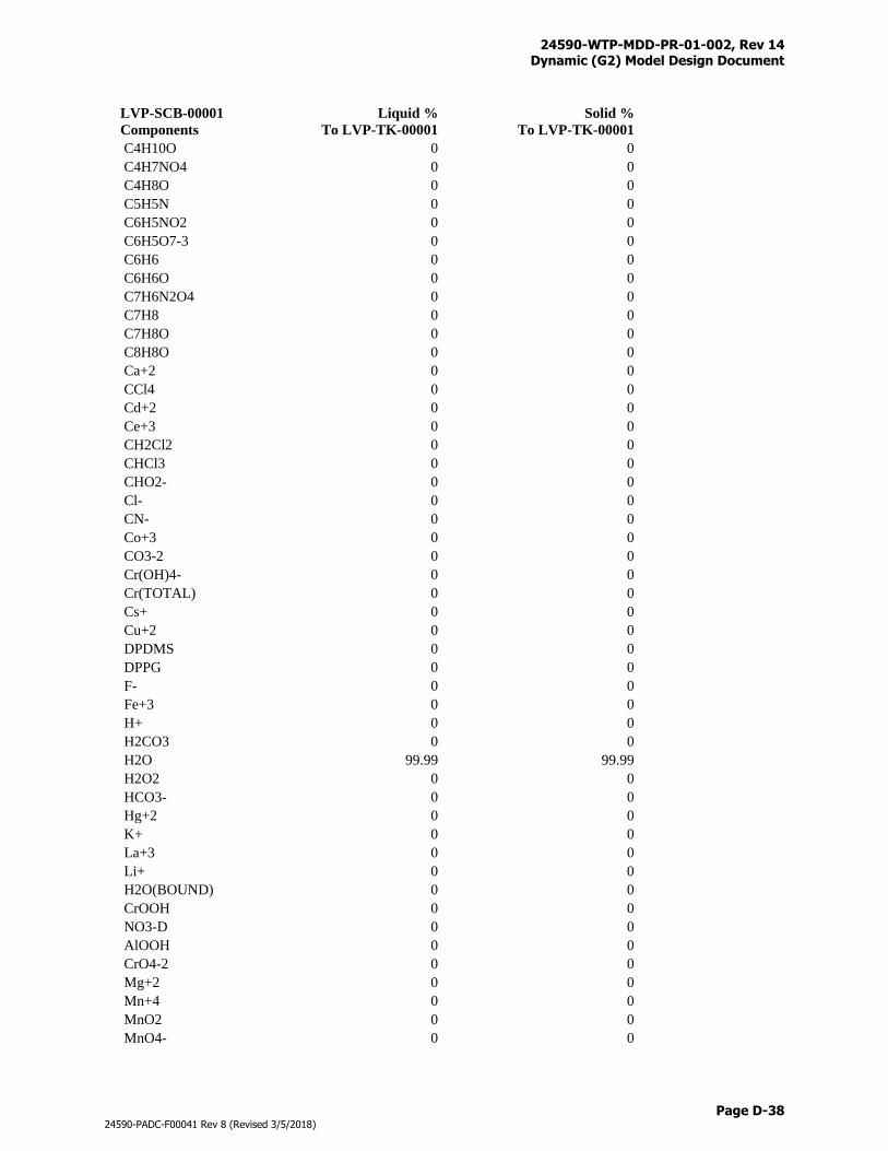
24590-WTP-MDD-PR-01-002, Rev 14 Dynamic (G2) Model Design Document
Page D-38
24590-PADC-F00041 Rev 8 (Revised 3/5/2018)
LVP-SCB-00001
Components
Liquid %
To LVP-TK-00001
Solid %
To LVP-TK-00001
C4H10O 0 0
C4H7NO4 0 0
C4H8O 0 0
C5H5N 0 0
C6H5NO2 0 0
C6H5O7-3 0 0
C6H6 0 0
C6H6O 0 0
C7H6N2O4 0 0
C7H8 0 0
C7H8O 0 0
C8H8O 0 0
Ca+2 0 0
CCl4 0 0
Cd+2 0 0
Ce+3 0 0
CH2Cl2 0 0
CHCl3 0 0
CHO2- 0 0
Cl- 0 0
CN- 0 0
Co+3 0 0
CO3-2 0 0
Cr(OH)4- 0 0
Cr(TOTAL) 0 0
Cs+ 0 0
Cu+2 0 0
DPDMS 0 0
DPPG 0 0
F- 0 0
Fe+3 0 0
H+ 0 0
H2CO3 0 0
H2O 99.99 99.99
H2O2 0 0
HCO3- 0 0
Hg+2 0 0
K+ 0 0
La+3 0 0
Li+ 0 0
H2O(BOUND) 0 0
CrOOH 0 0
NO3-D 0 0
AlOOH 0 0
CrO4-2 0 0
Mg+2 0 0
Mn+4 0 0
MnO2 0 0
MnO4- 0 0
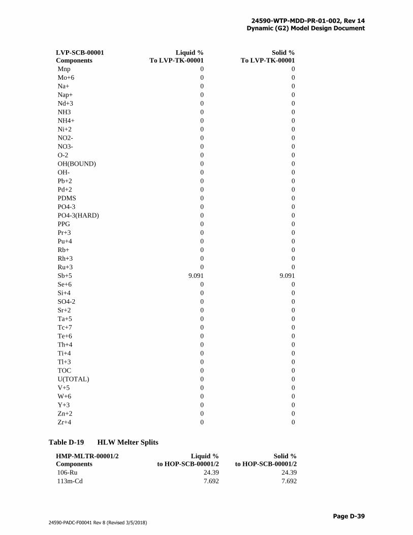
24590-WTP-MDD-PR-01-002, Rev 14 Dynamic (G2) Model Design Document
Page D-39
24590-PADC-F00041 Rev 8 (Revised 3/5/2018)
LVP-SCB-00001
Components
Liquid %
To LVP-TK-00001
Solid %
To LVP-TK-00001
Mnp 0 0
Mo+6 0 0
Na+ 0 0
Nap+ 0 0
Nd+3 0 0
NH3 0 0
NH4+ 0 0
Ni+2 0 0
NO2- 0 0
NO3- 0 0
O-2 0 0
OH(BOUND) 0 0
OH- 0 0
Pb+2 0 0
Pd+2 0 0
PDMS 0 0
PO4-3 0 0
PO4-3(HARD) 0 0
PPG 0 0
Pr+3 0 0
Pu+4 0 0
Rb+ 0 0
Rh+3 0 0
Ru+3 0 0
Sb+5 9.091 9.091
Se+6 0 0
Si+4 0 0
SO4-2 0 0
Sr+2 0 0
Ta+5 0 0
Tc+7 0 0
Te+6 0 0
Th+4 0 0
Ti+4 0 0
Tl+3 0 0
TOC 0 0
U(TOTAL) 0 0
V+5 0 0
W+6 0 0
Y+3 0 0
Zn+2 0 0
Zr+4 0 0
Table D-19 HLW Melter Splits
HMP-MLTR-00001/2
Components
Liquid %
to HOP-SCB-00001/2
Solid %
to HOP-SCB-00001/2
106-Ru 24.39 24.39
113m-Cd 7.692 7.692
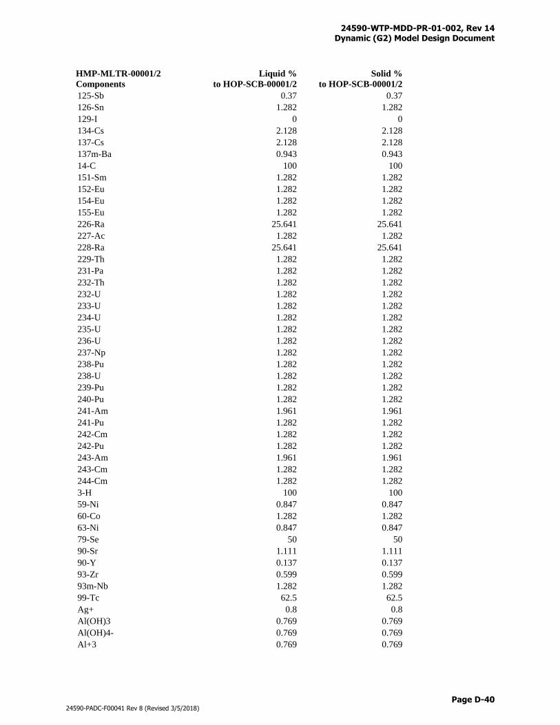
24590-WTP-MDD-PR-01-002, Rev 14 Dynamic (G2) Model Design Document
Page D-40
24590-PADC-F00041 Rev 8 (Revised 3/5/2018)
HMP-MLTR-00001/2
Components
Liquid %
to HOP-SCB-00001/2
Solid %
to HOP-SCB-00001/2
125-Sb 0.37 0.37
126-Sn 1.282 1.282
129-I 0 0
134-Cs 2.128 2.128
137-Cs 2.128 2.128
137m-Ba 0.943 0.943
14-C 100 100
151-Sm 1.282 1.282
152-Eu 1.282 1.282
154-Eu 1.282 1.282
155-Eu 1.282 1.282
226-Ra 25.641 25.641
227-Ac 1.282 1.282
228-Ra 25.641 25.641
229-Th 1.282 1.282
231-Pa 1.282 1.282
232-Th 1.282 1.282
232-U 1.282 1.282
233-U 1.282 1.282
234-U 1.282 1.282
235-U 1.282 1.282
236-U 1.282 1.282
237-Np 1.282 1.282
238-Pu 1.282 1.282
238-U 1.282 1.282
239-Pu 1.282 1.282
240-Pu 1.282 1.282
241-Am 1.961 1.961
241-Pu 1.282 1.282
242-Cm 1.282 1.282
242-Pu 1.282 1.282
243-Am 1.961 1.961
243-Cm 1.282 1.282
244-Cm 1.282 1.282
3-H 100 100
59-Ni 0.847 0.847
60-Co 1.282 1.282
63-Ni 0.847 0.847
79-Se 50 50
90-Sr 1.111 1.111
90-Y 0.137 0.137
93-Zr 0.599 0.599
93m-Nb 1.282 1.282
99-Tc 62.5 62.5
Ag+ 0.8 0.8
Al(OH)3 0.769 0.769
Al(OH)4- 0.769 0.769
Al+3 0.769 0.769
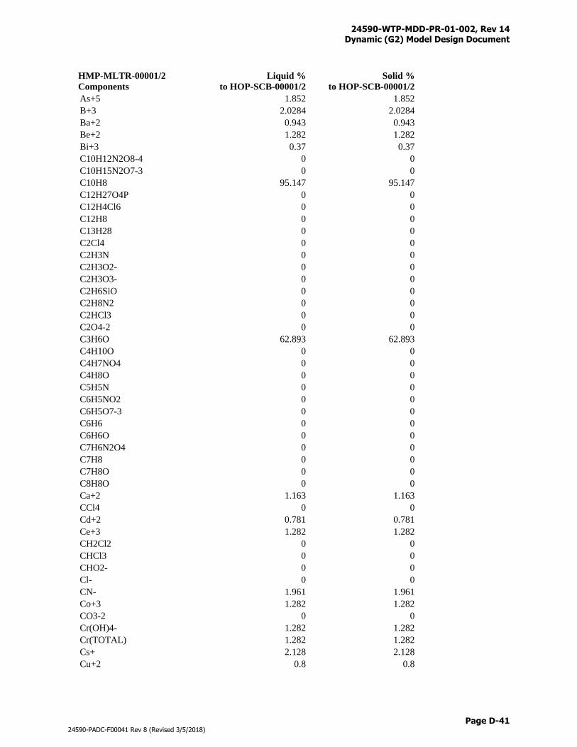
24590-WTP-MDD-PR-01-002, Rev 14 Dynamic (G2) Model Design Document
Page D-41
24590-PADC-F00041 Rev 8 (Revised 3/5/2018)
HMP-MLTR-00001/2
Components
Liquid %
to HOP-SCB-00001/2
Solid %
to HOP-SCB-00001/2
As+5 1.852 1.852
B+3 2.0284 2.0284
Ba+2 0.943 0.943
Be+2 1.282 1.282
Bi+3 0.37 0.37
C10H12N2O8-4 0 0
C10H15N2O7-3 0 0
C10H8 95.147 95.147
C12H27O4P 0 0
C12H4Cl6 0 0
C12H8 0 0
C13H28 0 0
C2Cl4 0 0
C2H3N 0 0
C2H3O2- 0 0
C2H3O3- 0 0
C2H6SiO 0 0
C2H8N2 0 0
C2HCl3 0 0
C2O4-2 0 0
C3H6O 62.893 62.893
C4H10O 0 0
C4H7NO4 0 0
C4H8O 0 0
C5H5N 0 0
C6H5NO2 0 0
C6H5O7-3 0 0
C6H6 0 0
C6H6O 0 0
C7H6N2O4 0 0
C7H8 0 0
C7H8O 0 0
C8H8O 0 0
Ca+2 1.163 1.163
CCl4 0 0
Cd+2 0.781 0.781
Ce+3 1.282 1.282
CH2Cl2 0 0
CHCl3 0 0
CHO2- 0 0
Cl- 0 0
CN- 1.961 1.961
Co+3 1.282 1.282
CO3-2 0 0
Cr(OH)4- 1.282 1.282
Cr(TOTAL) 1.282 1.282
Cs+ 2.128 2.128
Cu+2 0.8 0.8
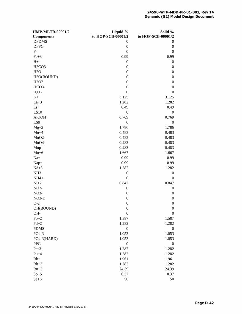
24590-WTP-MDD-PR-01-002, Rev 14 Dynamic (G2) Model Design Document
Page D-42
24590-PADC-F00041 Rev 8 (Revised 3/5/2018)
HMP-MLTR-00001/2
Components
Liquid %
to HOP-SCB-00001/2
Solid %
to HOP-SCB-00001/2
DPDMS 0 0
DPPG 0 0
F- 0 0
Fe+3 0.99 0.99
H+ 0 0
H2CO3 0 0
H2O 0 0
H2O(BOUND) 0 0
H2O2 0 0
HCO3- 0 0
Hg+2 0 0
K+ 3.125 3.125
La+3 1.282 1.282
Li+ 0.49 0.49
LS10 0 0
AlOOH 0.769 0.769
LS9 0 0
Mg+2 1.786 1.786
Mn+4 0.483 0.483
MnO2 0.483 0.483
MnO4- 0.483 0.483
Mnp 0.483 0.483
Mo+6 1.667 1.667
Na+ 0.99 0.99
Nap+ 0.99 0.99
Nd+3 1.282 1.282
NH3 0 0
NH4+ 0 0
Ni+2 0.847 0.847
NO2- 0 0
NO3- 0 0
NO3-D 0 0
O-2 0 0
OH(BOUND) 0 0
OH- 0 0
Pb+2 1.587 1.587
Pd+2 1.282 1.282
PDMS 0 0
PO4-3 1.053 1.053
PO4-3(HARD) 1.053 1.053
PPG 0 0
Pr+3 1.282 1.282
Pu+4 1.282 1.282
Rb+ 1.961 1.961
Rh+3 1.282 1.282
Ru+3 24.39 24.39
Sb+5 0.37 0.37
Se+6 50 50
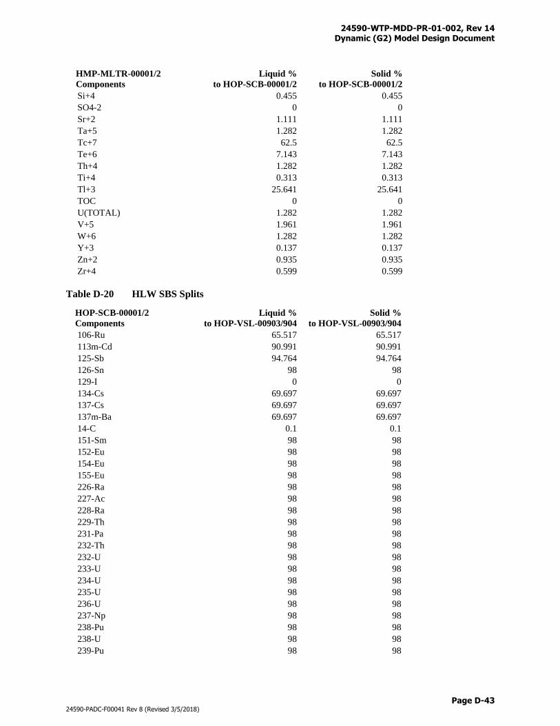
24590-WTP-MDD-PR-01-002, Rev 14 Dynamic (G2) Model Design Document
Page D-43
24590-PADC-F00041 Rev 8 (Revised 3/5/2018)
HMP-MLTR-00001/2
Components
Liquid %
to HOP-SCB-00001/2
Solid %
to HOP-SCB-00001/2
Si+4 0.455 0.455
SO4-2 0 0
Sr+2 1.111 1.111
Ta+5 1.282 1.282
Tc+7 62.5 62.5
Te+6 7.143 7.143
Th+4 1.282 1.282
Ti+4 0.313 0.313
Tl+3 25.641 25.641
TOC 0 0
U(TOTAL) 1.282 1.282
V+5 1.961 1.961
W+6 1.282 1.282
Y+3 0.137 0.137
Zn+2 0.935 0.935
Zr+4 0.599 0.599
Table D-20 HLW SBS Splits
HOP-SCB-00001/2
Components
Liquid %
to HOP-VSL-00903/904
Solid %
to HOP-VSL-00903/904
106-Ru 65.517 65.517
113m-Cd 90.991 90.991
125-Sb 94.764 94.764
126-Sn 98 98
129-I 0 0
134-Cs 69.697 69.697
137-Cs 69.697 69.697
137m-Ba 69.697 69.697
14-C 0.1 0.1
151-Sm 98 98
152-Eu 98 98
154-Eu 98 98
155-Eu 98 98
226-Ra 98 98
227-Ac 98 98
228-Ra 98 98
229-Th 98 98
231-Pa 98 98
232-Th 98 98
232-U 98 98
233-U 98 98
234-U 98 98
235-U 98 98
236-U 98 98
237-Np 98 98
238-Pu 98 98
238-U 98 98
239-Pu 98 98
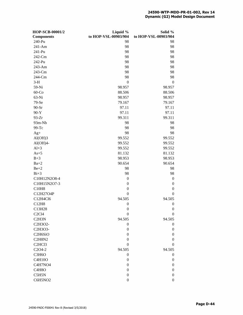
24590-WTP-MDD-PR-01-002, Rev 14 Dynamic (G2) Model Design Document
Page D-44
24590-PADC-F00041 Rev 8 (Revised 3/5/2018)
HOP-SCB-00001/2
Components
Liquid %
to HOP-VSL-00903/904
Solid %
to HOP-VSL-00903/904
240-Pu 98 98
241-Am 98 98
241-Pu 98 98
242-Cm 98 98
242-Pu 98 98
243-Am 98 98
243-Cm 98 98
244-Cm 98 98
3-H 0 0
59-Ni 98.957 98.957
60-Co 88.506 88.506
63-Ni 98.957 98.957
79-Se 79.167 79.167
90-Sr 97.11 97.11
90-Y 97.11 97.11
93-Zr 99.311 99.311
93m-Nb 98 98
99-Tc 98 98
Ag+ 98 98
Al(OH)3 99.552 99.552
Al(OH)4- 99.552 99.552
Al+3 99.552 99.552
As+5 81.132 81.132
B+3 98.953 98.953
Ba+2 90.654 90.654
Be+2 98 98
Bi+3 98 98
C10H12N2O8-4 0 0
C10H15N2O7-3 0 0
C10H8 0 0
C12H27O4P 0 0
C12H4Cl6 94.505 94.505
C12H8 0 0
C13H28 0 0
C2Cl4 0 0
C2H3N 94.505 94.505
C2H3O2- 0 0
C2H3O3- 0 0
C2H6SiO 0 0
C2H8N2 0 0
C2HCl3 0 0
C2O4-2 94.505 94.505
C3H6O 0 0
C4H10O 0 0
C4H7NO4 0 0
C4H8O 0 0
C5H5N 0 0
C6H5NO2 0 0
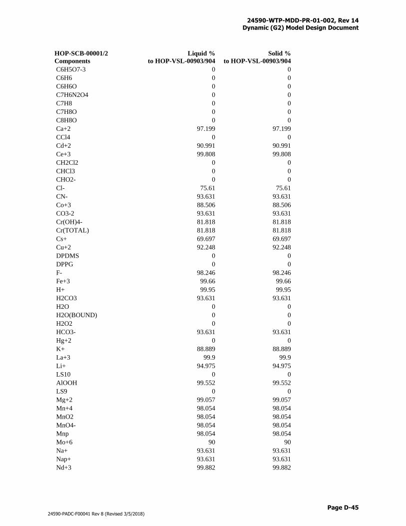
24590-WTP-MDD-PR-01-002, Rev 14 Dynamic (G2) Model Design Document
Page D-45
24590-PADC-F00041 Rev 8 (Revised 3/5/2018)
HOP-SCB-00001/2
Components
Liquid %
to HOP-VSL-00903/904
Solid %
to HOP-VSL-00903/904
C6H5O7-3 0 0
C6H6 0 0
C6H6O 0 0
C7H6N2O4 0 0
C7H8 0 0
C7H8O 0 0
C8H8O 0 0
Ca+2 97.199 97.199
CCl4 0 0
Cd+2 90.991 90.991
Ce+3 99.808 99.808
CH2Cl2 0 0
CHCl3 0 0
CHO2- 0 0
Cl- 75.61 75.61
CN- 93.631 93.631
Co+3 88.506 88.506
CO3-2 93.631 93.631
Cr(OH)4- 81.818 81.818
Cr(TOTAL) 81.818 81.818
Cs+ 69.697 69.697
Cu+2 92.248 92.248
DPDMS 0 0
DPPG 0 0
F- 98.246 98.246
Fe+3 99.66 99.66
H+ 99.95 99.95
H2CO3 93.631 93.631
H2O 0 0
H2O(BOUND) 0 0
H2O2 0 0
HCO3- 93.631 93.631
Hg+2 0 0
K+ 88.889 88.889
La+3 99.9 99.9
Li+ 94.975 94.975
LS10 0 0
AlOOH 99.552 99.552
LS9 0 0
Mg+2 99.057 99.057
Mn+4 98.054 98.054
MnO2 98.054 98.054
MnO4- 98.054 98.054
Mnp 98.054 98.054
Mo+6 90 90
Na+ 93.631 93.631
Nap+ 93.631 93.631
Nd+3 99.882 99.882
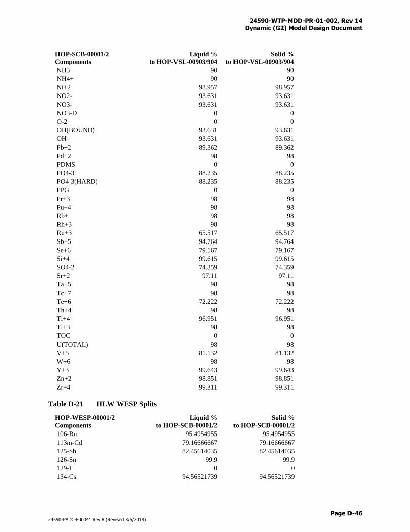
24590-WTP-MDD-PR-01-002, Rev 14 Dynamic (G2) Model Design Document
Page D-46
24590-PADC-F00041 Rev 8 (Revised 3/5/2018)
HOP-SCB-00001/2
Components
Liquid %
to HOP-VSL-00903/904
Solid %
to HOP-VSL-00903/904
NH3 90 90
NH4+ 90 90
Ni+2 98.957 98.957
NO2- 93.631 93.631
NO3- 93.631 93.631
NO3-D 0 0
O-2 0 0
OH(BOUND) 93.631 93.631
OH- 93.631 93.631
Pb+2 89.362 89.362
Pd+2 98 98
PDMS 0 0
PO4-3 88.235 88.235
PO4-3(HARD) 88.235 88.235
PPG 0 0
Pr+3 98 98
Pu+4 98 98
Rb+ 98 98
Rh+3 98 98
Ru+3 65.517 65.517
Sb+5 94.764 94.764
Se+6 79.167 79.167
Si+4 99.615 99.615
SO4-2 74.359 74.359
Sr+2 97.11 97.11
Ta+5 98 98
Tc+7 98 98
Te+6 72.222 72.222
Th+4 98 98
Ti+4 96.951 96.951
Tl+3 98 98
TOC 0 0
U(TOTAL) 98 98
V+5 81.132 81.132
W+6 98 98
Y+3 99.643 99.643
Zn+2 98.851 98.851
Zr+4 99.311 99.311
Table D-21 HLW WESP Splits
HOP-WESP-00001/2
Components
Liquid %
to HOP-SCB-00001/2
Solid %
to HOP-SCB-00001/2
106-Ru 95.4954955 95.4954955
113m-Cd 79.16666667 79.16666667
125-Sb 82.45614035 82.45614035
126-Sn 99.9 99.9
129-I 0 0
134-Cs 94.56521739 94.56521739
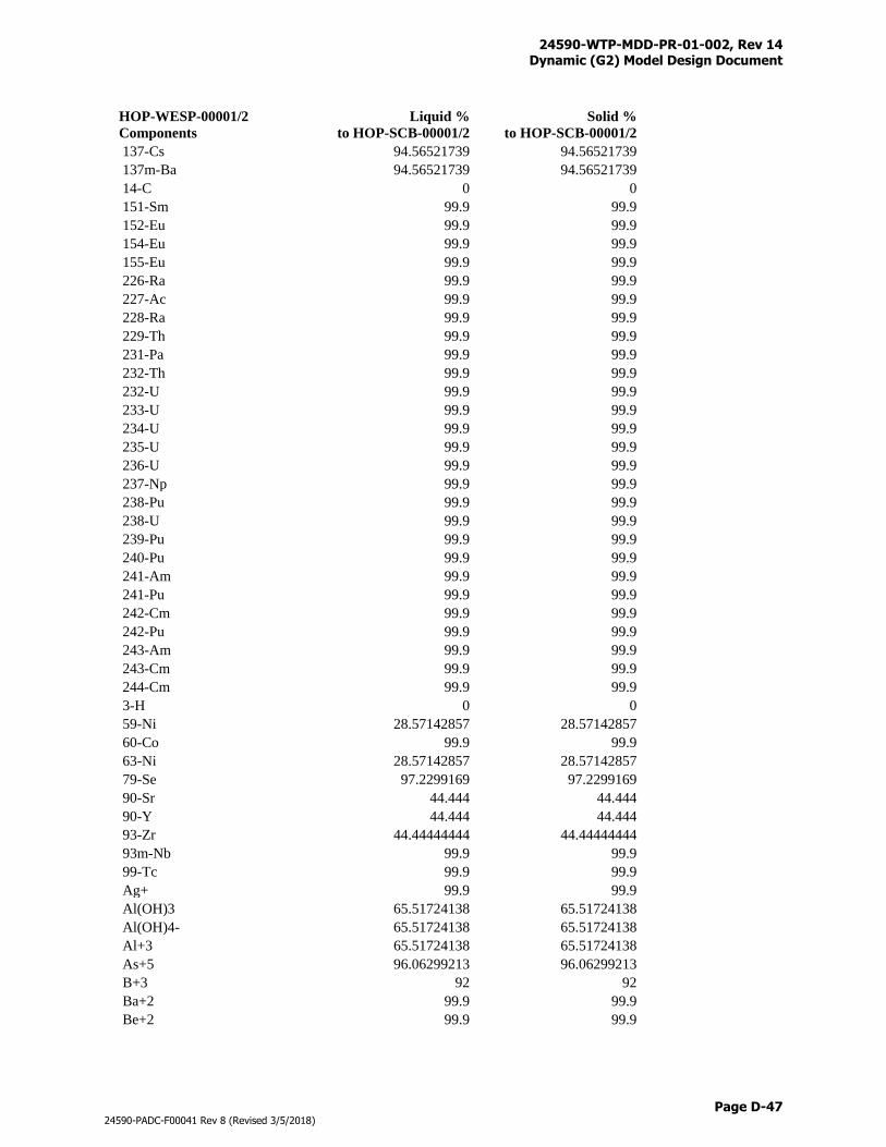
24590-WTP-MDD-PR-01-002, Rev 14 Dynamic (G2) Model Design Document
Page D-47
24590-PADC-F00041 Rev 8 (Revised 3/5/2018)
HOP-WESP-00001/2
Components
Liquid %
to HOP-SCB-00001/2
Solid %
to HOP-SCB-00001/2
137-Cs 94.56521739 94.56521739
137m-Ba 94.56521739 94.56521739
14-C 0 0
151-Sm 99.9 99.9
152-Eu 99.9 99.9
154-Eu 99.9 99.9
155-Eu 99.9 99.9
226-Ra 99.9 99.9
227-Ac 99.9 99.9
228-Ra 99.9 99.9
229-Th 99.9 99.9
231-Pa 99.9 99.9
232-Th 99.9 99.9
232-U 99.9 99.9
233-U 99.9 99.9
234-U 99.9 99.9
235-U 99.9 99.9
236-U 99.9 99.9
237-Np 99.9 99.9
238-Pu 99.9 99.9
238-U 99.9 99.9
239-Pu 99.9 99.9
240-Pu 99.9 99.9
241-Am 99.9 99.9
241-Pu 99.9 99.9
242-Cm 99.9 99.9
242-Pu 99.9 99.9
243-Am 99.9 99.9
243-Cm 99.9 99.9
244-Cm 99.9 99.9
3-H 0 0
59-Ni 28.57142857 28.57142857
60-Co 99.9 99.9
63-Ni 28.57142857 28.57142857
79-Se 97.2299169 97.2299169
90-Sr 44.444 44.444
90-Y 44.444 44.444
93-Zr 44.44444444 44.44444444
93m-Nb 99.9 99.9
99-Tc 99.9 99.9
Ag+ 99.9 99.9
Al(OH)3 65.51724138 65.51724138
Al(OH)4- 65.51724138 65.51724138
Al+3 65.51724138 65.51724138
As+5 96.06299213 96.06299213
B+3 92 92
Ba+2 99.9 99.9
Be+2 99.9 99.9
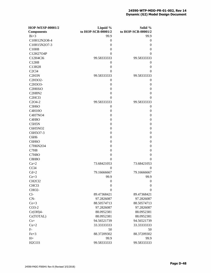
24590-WTP-MDD-PR-01-002, Rev 14 Dynamic (G2) Model Design Document
Page D-48
24590-PADC-F00041 Rev 8 (Revised 3/5/2018)
HOP-WESP-00001/2
Components
Liquid %
to HOP-SCB-00001/2
Solid %
to HOP-SCB-00001/2
Bi+3 99.9 99.9
C10H12N2O8-4 0 0
C10H15N2O7-3 0 0
C10H8 0 0
C12H27O4P 0 0
C12H4Cl6 99.58333333 99.58333333
C12H8 0 0
C13H28 0 0
C2Cl4 0 0
C2H3N 99.58333333 99.58333333
C2H3O2- 0 0
C2H3O3- 0 0
C2H6SiO 0 0
C2H8N2 0 0
C2HCl3 0 0
C2O4-2 99.58333333 99.58333333
C3H6O 0 0
C4H10O 0 0
C4H7NO4 0 0
C4H8O 0 0
C5H5N 0 0
C6H5NO2 0 0
C6H5O7-3 0 0
C6H6 0 0
C6H6O 0 0
C7H6N2O4 0 0
C7H8 0 0
C7H8O 0 0
C8H8O 0 0
Ca+2 73.68421053 73.68421053
CCl4 0 0
Cd+2 79.16666667 79.16666667
Ce+3 99.9 99.9
CH2Cl2 0 0
CHCl3 0 0
CHO2- 0 0
Cl- 89.47368421 89.47368421
CN- 97.2826087 97.2826087
Co+3 88.50574713 88.50574713
CO3-2 97.2826087 97.2826087
Cr(OH)4- 88.0952381 88.0952381
Cr(TOTAL) 88.0952381 88.0952381
Cs+ 94.56521739 94.56521739
Cu+2 33.33333333 33.33333333
F- 50 50
Fe+3 88.37209302 88.37209302
H+ 99.9 99.9
H2CO3 99.58333333 99.58333333
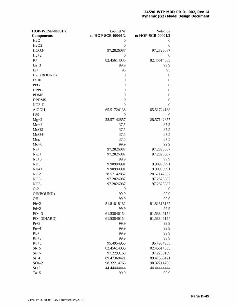
24590-WTP-MDD-PR-01-002, Rev 14 Dynamic (G2) Model Design Document
Page D-49
24590-PADC-F00041 Rev 8 (Revised 3/5/2018)
HOP-WESP-00001/2
Components
Liquid %
to HOP-SCB-00001/2
Solid %
to HOP-SCB-00001/2
H2O 0 0
H2O2 0 0
HCO3- 97.2826087 97.2826087
Hg+2 0 0
K+ 82.45614035 82.45614035
La+3 99.9 99.9
Li+ 95 95
H2O(BOUND) 0 0
LS10 0 0
PPG 0 0
DPPG 0 0
PDMS 0 0
DPDMS 0 0
NO3-D 0 0
AlOOH 65.51724138 65.51724138
LS9 0 0
Mg+2 28.57142857 28.57142857
Mn+4 37.5 37.5
MnO2 37.5 37.5
MnO4- 37.5 37.5
Mnp 37.5 37.5
Mo+6 99.9 99.9
Na+ 97.2826087 97.2826087
Nap+ 97.2826087 97.2826087
Nd+3 99.9 99.9
NH3 9.90990991 9.90990991
NH4+ 9.90990991 9.90990991
Ni+2 28.57142857 28.57142857
NO2- 97.2826087 97.2826087
NO3- 97.2826087 97.2826087
O-2 0 0
OH(BOUND) 99.9 99.9
OH- 99.9 99.9
Pb+2 81.81818182 81.81818182
Pd+2 99.9 99.9
PO4-3 61.53846154 61.53846154
PO4-3(HARD) 61.53846154 61.53846154
Pr+3 99.9 99.9
Pu+4 99.9 99.9
Rb+ 99.9 99.9
Rh+3 99.9 99.9
Ru+3 95.4954955 95.4954955
Sb+5 82.45614035 82.45614035
Se+6 97.2299169 97.2299169
Si+4 89.47368421 89.47368421
SO4-2 98.32214765 98.32214765
Sr+2 44.44444444 44.44444444
Ta+5 99.9 99.9
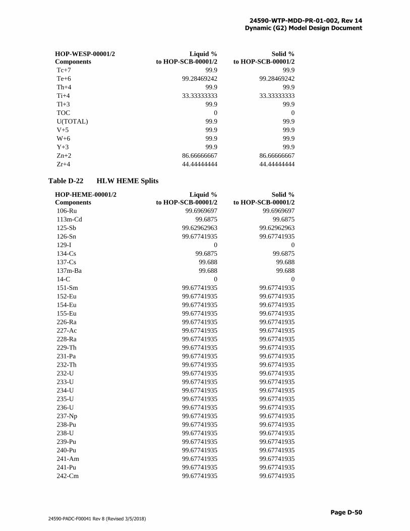
24590-WTP-MDD-PR-01-002, Rev 14 Dynamic (G2) Model Design Document
Page D-50
24590-PADC-F00041 Rev 8 (Revised 3/5/2018)
HOP-WESP-00001/2
Components
Liquid %
to HOP-SCB-00001/2
Solid %
to HOP-SCB-00001/2
Tc+7 99.9 99.9
Te+6 99.28469242 99.28469242
Th+4 99.9 99.9
Ti+4 33.33333333 33.33333333
Tl+3 99.9 99.9
TOC 0 0
U(TOTAL) 99.9 99.9
V+5 99.9 99.9
W+6 99.9 99.9
Y+3 99.9 99.9
Zn+2 86.66666667 86.66666667
Zr+4 44.44444444 44.44444444
Table D-22 HLW HEME Splits
HOP-HEME-00001/2
Components
Liquid %
to HOP-SCB-00001/2
Solid %
to HOP-SCB-00001/2
106-Ru 99.6969697 99.6969697
113m-Cd 99.6875 99.6875
125-Sb 99.62962963 99.62962963
126-Sn 99.67741935 99.67741935
129-I 0 0
134-Cs 99.6875 99.6875
137-Cs 99.688 99.688
137m-Ba 99.688 99.688
14-C 0 0
151-Sm 99.67741935 99.67741935
152-Eu 99.67741935 99.67741935
154-Eu 99.67741935 99.67741935
155-Eu 99.67741935 99.67741935
226-Ra 99.67741935 99.67741935
227-Ac 99.67741935 99.67741935
228-Ra 99.67741935 99.67741935
229-Th 99.67741935 99.67741935
231-Pa 99.67741935 99.67741935
232-Th 99.67741935 99.67741935
232-U 99.67741935 99.67741935
233-U 99.67741935 99.67741935
234-U 99.67741935 99.67741935
235-U 99.67741935 99.67741935
236-U 99.67741935 99.67741935
237-Np 99.67741935 99.67741935
238-Pu 99.67741935 99.67741935
238-U 99.67741935 99.67741935
239-Pu 99.67741935 99.67741935
240-Pu 99.67741935 99.67741935
241-Am 99.67741935 99.67741935
241-Pu 99.67741935 99.67741935
242-Cm 99.67741935 99.67741935
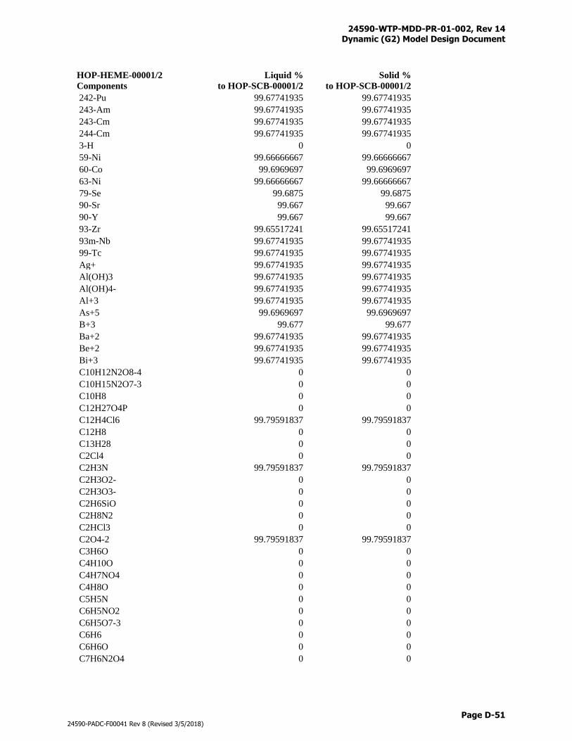
24590-WTP-MDD-PR-01-002, Rev 14 Dynamic (G2) Model Design Document
Page D-51
24590-PADC-F00041 Rev 8 (Revised 3/5/2018)
HOP-HEME-00001/2
Components
Liquid %
to HOP-SCB-00001/2
Solid %
to HOP-SCB-00001/2
242-Pu 99.67741935 99.67741935
243-Am 99.67741935 99.67741935
243-Cm 99.67741935 99.67741935
244-Cm 99.67741935 99.67741935
3-H 0 0
59-Ni 99.66666667 99.66666667
60-Co 99.6969697 99.6969697
63-Ni 99.66666667 99.66666667
79-Se 99.6875 99.6875
90-Sr 99.667 99.667
90-Y 99.667 99.667
93-Zr 99.65517241 99.65517241
93m-Nb 99.67741935 99.67741935
99-Tc 99.67741935 99.67741935
Ag+ 99.67741935 99.67741935
Al(OH)3 99.67741935 99.67741935
Al(OH)4- 99.67741935 99.67741935
Al+3 99.67741935 99.67741935
As+5 99.6969697 99.6969697
B+3 99.677 99.677
Ba+2 99.67741935 99.67741935
Be+2 99.67741935 99.67741935
Bi+3 99.67741935 99.67741935
C10H12N2O8-4 0 0
C10H15N2O7-3 0 0
C10H8 0 0
C12H27O4P 0 0
C12H4Cl6 99.79591837 99.79591837
C12H8 0 0
C13H28 0 0
C2Cl4 0 0
C2H3N 99.79591837 99.79591837
C2H3O2- 0 0
C2H3O3- 0 0
C2H6SiO 0 0
C2H8N2 0 0
C2HCl3 0 0
C2O4-2 99.79591837 99.79591837
C3H6O 0 0
C4H10O 0 0
C4H7NO4 0 0
C4H8O 0 0
C5H5N 0 0
C6H5NO2 0 0
C6H5O7-3 0 0
C6H6 0 0
C6H6O 0 0
C7H6N2O4 0 0
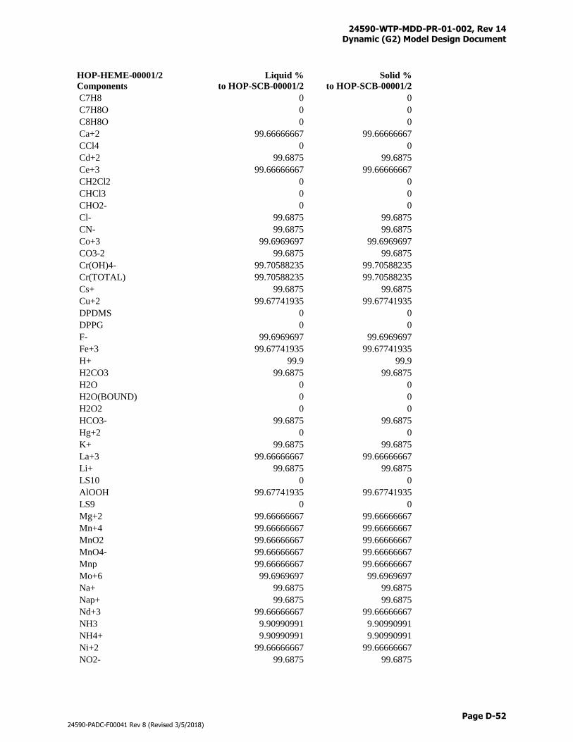
24590-WTP-MDD-PR-01-002, Rev 14 Dynamic (G2) Model Design Document
Page D-52
24590-PADC-F00041 Rev 8 (Revised 3/5/2018)
HOP-HEME-00001/2
Components
Liquid %
to HOP-SCB-00001/2
Solid %
to HOP-SCB-00001/2
C7H8 0 0
C7H8O 0 0
C8H8O 0 0
Ca+2 99.66666667 99.66666667
CCl4 0 0
Cd+2 99.6875 99.6875
Ce+3 99.66666667 99.66666667
CH2Cl2 0 0
CHCl3 0 0
CHO2- 0 0
Cl- 99.6875 99.6875
CN- 99.6875 99.6875
Co+3 99.6969697 99.6969697
CO3-2 99.6875 99.6875
Cr(OH)4- 99.70588235 99.70588235
Cr(TOTAL) 99.70588235 99.70588235
Cs+ 99.6875 99.6875
Cu+2 99.67741935 99.67741935
DPDMS 0 0
DPPG 0 0
F- 99.6969697 99.6969697
Fe+3 99.67741935 99.67741935
H+ 99.9 99.9
H2CO3 99.6875 99.6875
H2O 0 0
H2O(BOUND) 0 0
H2O2 0 0
HCO3- 99.6875 99.6875
Hg+2 0 0
K+ 99.6875 99.6875
La+3 99.66666667 99.66666667
Li+ 99.6875 99.6875
LS10 0 0
AlOOH 99.67741935 99.67741935
LS9 0 0
Mg+2 99.66666667 99.66666667
Mn+4 99.66666667 99.66666667
MnO2 99.66666667 99.66666667
MnO4- 99.66666667 99.66666667
Mnp 99.66666667 99.66666667
Mo+6 99.6969697 99.6969697
Na+ 99.6875 99.6875
Nap+ 99.6875 99.6875
Nd+3 99.66666667 99.66666667
NH3 9.90990991 9.90990991
NH4+ 9.90990991 9.90990991
Ni+2 99.66666667 99.66666667
NO2- 99.6875 99.6875
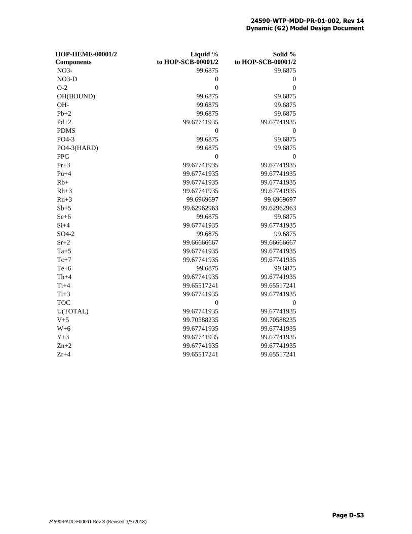
24590-WTP-MDD-PR-01-002, Rev 14 Dynamic (G2) Model Design Document
Page D-53
24590-PADC-F00041 Rev 8 (Revised 3/5/2018)
HOP-HEME-00001/2
Components
Liquid %
to HOP-SCB-00001/2
Solid %
to HOP-SCB-00001/2
NO3- 99.6875 99.6875
NO3-D 0 0
O-2 0 0
OH(BOUND) 99.6875 99.6875
OH- 99.6875 99.6875
Pb+2 99.6875 99.6875
Pd+2 99.67741935 99.67741935
PDMS 0 0
PO4-3 99.6875 99.6875
PO4-3(HARD) 99.6875 99.6875
PPG 0 0
Pr+3 99.67741935 99.67741935
Pu+4 99.67741935 99.67741935
Rb+ 99.67741935 99.67741935
Rh+3 99.67741935 99.67741935
Ru+3 99.6969697 99.6969697
Sb+5 99.62962963 99.62962963
Se+6 99.6875 99.6875
Si+4 99.67741935 99.67741935
SO4-2 99.6875 99.6875
Sr+2 99.66666667 99.66666667
Ta+5 99.67741935 99.67741935
Tc+7 99.67741935 99.67741935
Te+6 99.6875 99.6875
Th+4 99.67741935 99.67741935
Ti+4 99.65517241 99.65517241
Tl+3 99.67741935 99.67741935
TOC 0 0
U(TOTAL) 99.67741935 99.67741935
V+5 99.70588235 99.70588235
W+6 99.67741935 99.67741935
Y+3 99.67741935 99.67741935
Zn+2 99.67741935 99.67741935
Zr+4 99.65517241 99.65517241
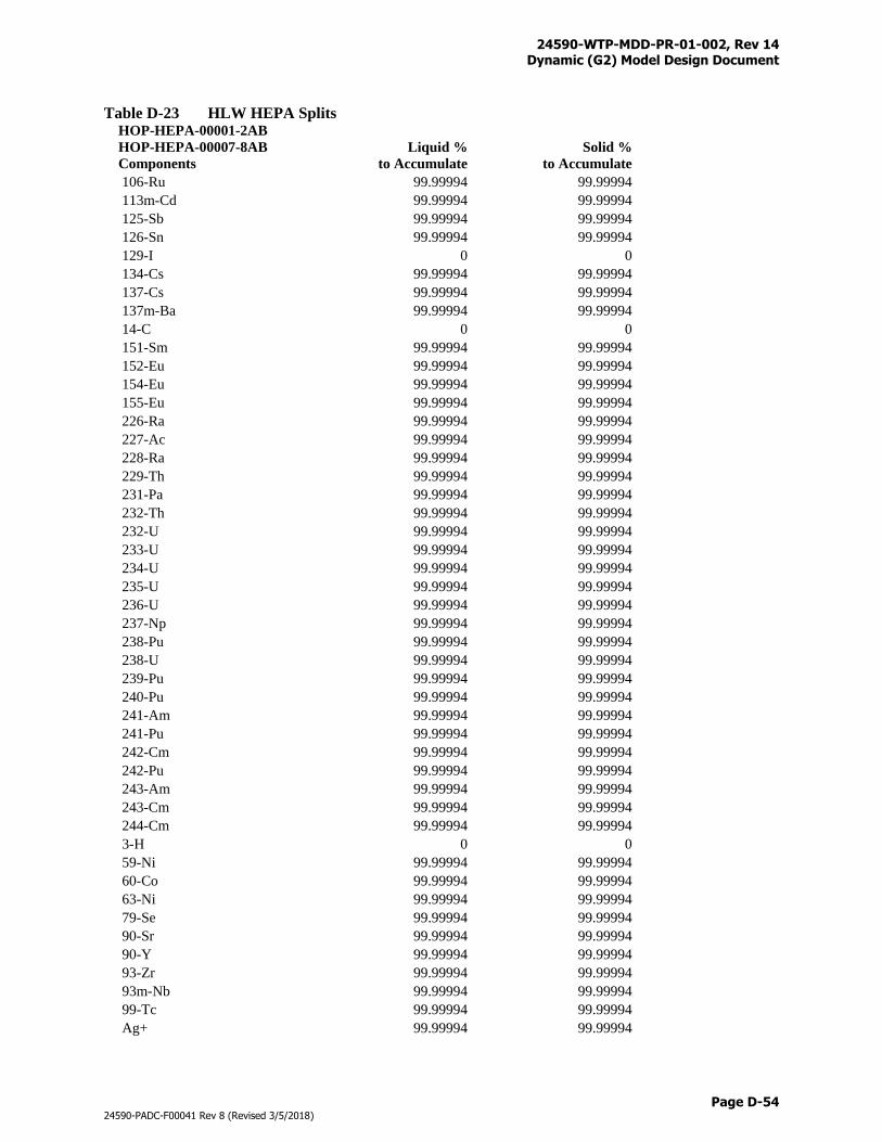
24590-WTP-MDD-PR-01-002, Rev 14 Dynamic (G2) Model Design Document
Page D-54
24590-PADC-F00041 Rev 8 (Revised 3/5/2018)
Table D-23 HLW HEPA Splits HOP-HEPA-00001-2AB
HOP-HEPA-00007-8AB
Components
Liquid %
to Accumulate
Solid %
to Accumulate
106-Ru 99.99994 99.99994
113m-Cd 99.99994 99.99994
125-Sb 99.99994 99.99994
126-Sn 99.99994 99.99994
129-I 0 0
134-Cs 99.99994 99.99994
137-Cs 99.99994 99.99994
137m-Ba 99.99994 99.99994
14-C 0 0
151-Sm 99.99994 99.99994
152-Eu 99.99994 99.99994
154-Eu 99.99994 99.99994
155-Eu 99.99994 99.99994
226-Ra 99.99994 99.99994
227-Ac 99.99994 99.99994
228-Ra 99.99994 99.99994
229-Th 99.99994 99.99994
231-Pa 99.99994 99.99994
232-Th 99.99994 99.99994
232-U 99.99994 99.99994
233-U 99.99994 99.99994
234-U 99.99994 99.99994
235-U 99.99994 99.99994
236-U 99.99994 99.99994
237-Np 99.99994 99.99994
238-Pu 99.99994 99.99994
238-U 99.99994 99.99994
239-Pu 99.99994 99.99994
240-Pu 99.99994 99.99994
241-Am 99.99994 99.99994
241-Pu 99.99994 99.99994
242-Cm 99.99994 99.99994
242-Pu 99.99994 99.99994
243-Am 99.99994 99.99994
243-Cm 99.99994 99.99994
244-Cm 99.99994 99.99994
3-H 0 0
59-Ni 99.99994 99.99994
60-Co 99.99994 99.99994
63-Ni 99.99994 99.99994
79-Se 99.99994 99.99994
90-Sr 99.99994 99.99994
90-Y 99.99994 99.99994
93-Zr 99.99994 99.99994
93m-Nb 99.99994 99.99994
99-Tc 99.99994 99.99994
Ag+ 99.99994 99.99994
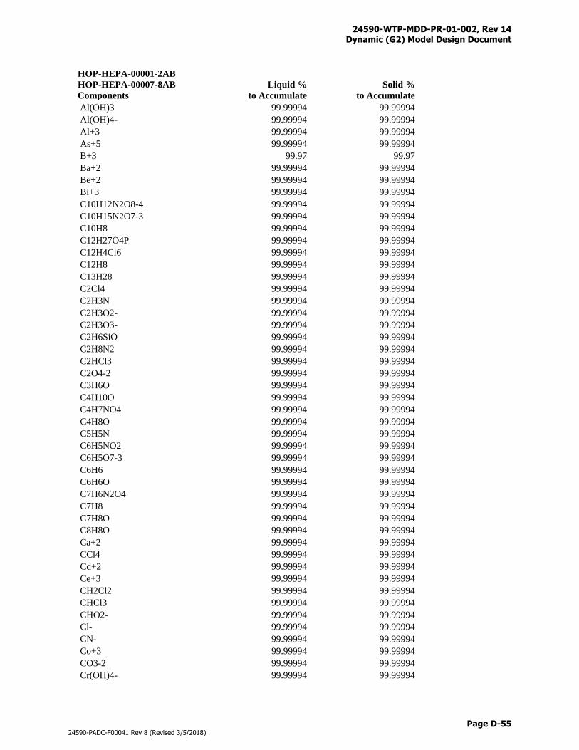
24590-WTP-MDD-PR-01-002, Rev 14 Dynamic (G2) Model Design Document
Page D-55
24590-PADC-F00041 Rev 8 (Revised 3/5/2018)
HOP-HEPA-00001-2AB
HOP-HEPA-00007-8AB
Components
Liquid %
to Accumulate
Solid %
to Accumulate
Al(OH)3 99.99994 99.99994
Al(OH)4- 99.99994 99.99994
Al+3 99.99994 99.99994
As+5 99.99994 99.99994
B+3 99.97 99.97
Ba+2 99.99994 99.99994
Be+2 99.99994 99.99994
Bi+3 99.99994 99.99994
C10H12N2O8-4 99.99994 99.99994
C10H15N2O7-3 99.99994 99.99994
C10H8 99.99994 99.99994
C12H27O4P 99.99994 99.99994
C12H4Cl6 99.99994 99.99994
C12H8 99.99994 99.99994
C13H28 99.99994 99.99994
C2Cl4 99.99994 99.99994
C2H3N 99.99994 99.99994
C2H3O2- 99.99994 99.99994
C2H3O3- 99.99994 99.99994
C2H6SiO 99.99994 99.99994
C2H8N2 99.99994 99.99994
C2HCl3 99.99994 99.99994
C2O4-2 99.99994 99.99994
C3H6O 99.99994 99.99994
C4H10O 99.99994 99.99994
C4H7NO4 99.99994 99.99994
C4H8O 99.99994 99.99994
C5H5N 99.99994 99.99994
C6H5NO2 99.99994 99.99994
C6H5O7-3 99.99994 99.99994
C6H6 99.99994 99.99994
C6H6O 99.99994 99.99994
C7H6N2O4 99.99994 99.99994
C7H8 99.99994 99.99994
C7H8O 99.99994 99.99994
C8H8O 99.99994 99.99994
Ca+2 99.99994 99.99994
CCl4 99.99994 99.99994
Cd+2 99.99994 99.99994
Ce+3 99.99994 99.99994
CH2Cl2 99.99994 99.99994
CHCl3 99.99994 99.99994
CHO2- 99.99994 99.99994
Cl- 99.99994 99.99994
CN- 99.99994 99.99994
Co+3 99.99994 99.99994
CO3-2 99.99994 99.99994
Cr(OH)4- 99.99994 99.99994
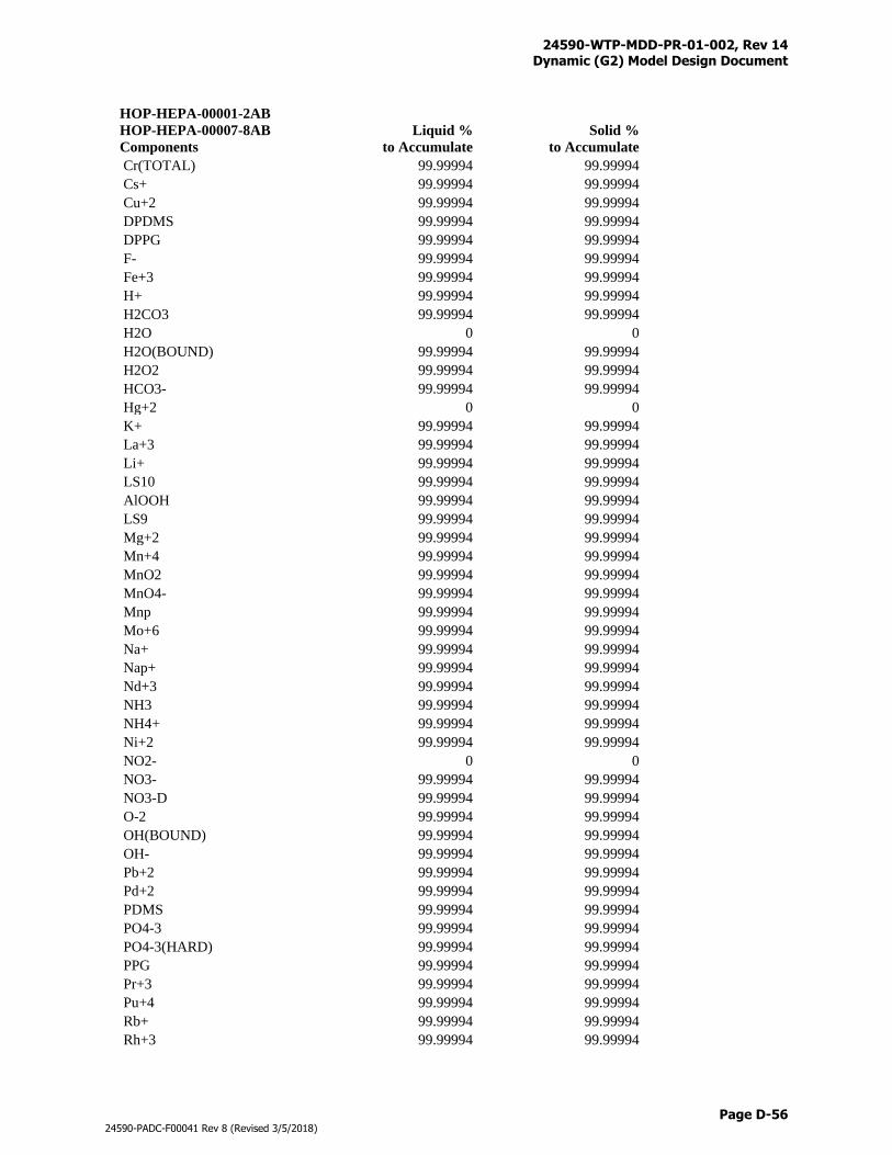
24590-WTP-MDD-PR-01-002, Rev 14 Dynamic (G2) Model Design Document
Page D-56
24590-PADC-F00041 Rev 8 (Revised 3/5/2018)
HOP-HEPA-00001-2AB
HOP-HEPA-00007-8AB
Components
Liquid %
to Accumulate
Solid %
to Accumulate
Cr(TOTAL) 99.99994 99.99994
Cs+ 99.99994 99.99994
Cu+2 99.99994 99.99994
DPDMS 99.99994 99.99994
DPPG 99.99994 99.99994
F- 99.99994 99.99994
Fe+3 99.99994 99.99994
H+ 99.99994 99.99994
H2CO3 99.99994 99.99994
H2O 0 0
H2O(BOUND) 99.99994 99.99994
H2O2 99.99994 99.99994
HCO3- 99.99994 99.99994
Hg+2 0 0
K+ 99.99994 99.99994
La+3 99.99994 99.99994
Li+ 99.99994 99.99994
LS10 99.99994 99.99994
AlOOH 99.99994 99.99994
LS9 99.99994 99.99994
Mg+2 99.99994 99.99994
Mn+4 99.99994 99.99994
MnO2 99.99994 99.99994
MnO4- 99.99994 99.99994
Mnp 99.99994 99.99994
Mo+6 99.99994 99.99994
Na+ 99.99994 99.99994
Nap+ 99.99994 99.99994
Nd+3 99.99994 99.99994
NH3 99.99994 99.99994
NH4+ 99.99994 99.99994
Ni+2 99.99994 99.99994
NO2- 0 0
NO3- 99.99994 99.99994
NO3-D 99.99994 99.99994
O-2 99.99994 99.99994
OH(BOUND) 99.99994 99.99994
OH- 99.99994 99.99994
Pb+2 99.99994 99.99994
Pd+2 99.99994 99.99994
PDMS 99.99994 99.99994
PO4-3 99.99994 99.99994
PO4-3(HARD) 99.99994 99.99994
PPG 99.99994 99.99994
Pr+3 99.99994 99.99994
Pu+4 99.99994 99.99994
Rb+ 99.99994 99.99994
Rh+3 99.99994 99.99994
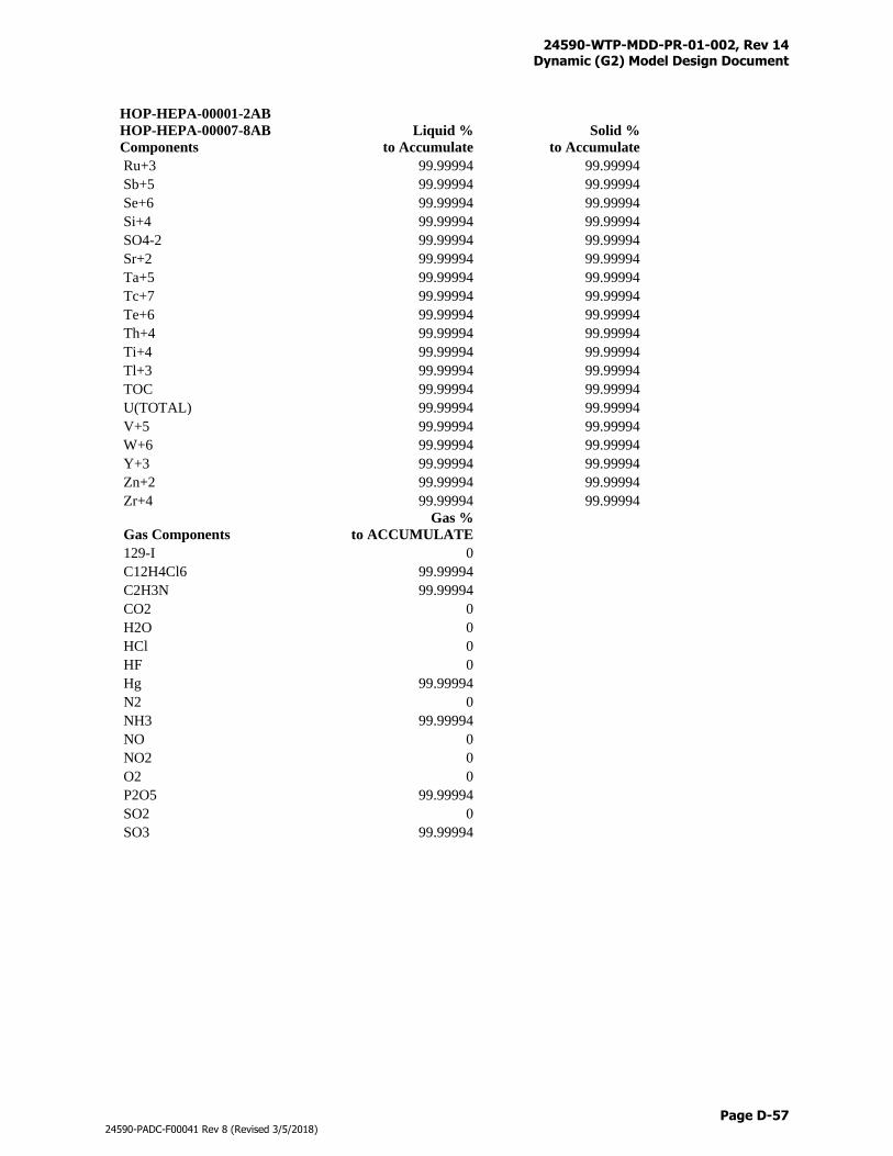
24590-WTP-MDD-PR-01-002, Rev 14 Dynamic (G2) Model Design Document
Page D-57
24590-PADC-F00041 Rev 8 (Revised 3/5/2018)
HOP-HEPA-00001-2AB
HOP-HEPA-00007-8AB
Components
Liquid %
to Accumulate
Solid %
to Accumulate
Ru+3 99.99994 99.99994
Sb+5 99.99994 99.99994
Se+6 99.99994 99.99994
Si+4 99.99994 99.99994
SO4-2 99.99994 99.99994
Sr+2 99.99994 99.99994
Ta+5 99.99994 99.99994
Tc+7 99.99994 99.99994
Te+6 99.99994 99.99994
Th+4 99.99994 99.99994
Ti+4 99.99994 99.99994
Tl+3 99.99994 99.99994
TOC 99.99994 99.99994
U(TOTAL) 99.99994 99.99994
V+5 99.99994 99.99994
W+6 99.99994 99.99994
Y+3 99.99994 99.99994
Zn+2 99.99994 99.99994
Zr+4 99.99994 99.99994
Gas Components
Gas %
to ACCUMULATE
129-I 0
C12H4Cl6 99.99994
C2H3N 99.99994
CO2 0
H2O 0
HCl 0
HF 0
Hg 99.99994
N2 0
NH3 99.99994
NO 0
NO2 0
O2 0
P2O5 99.99994
SO2 0
SO3 99.99994
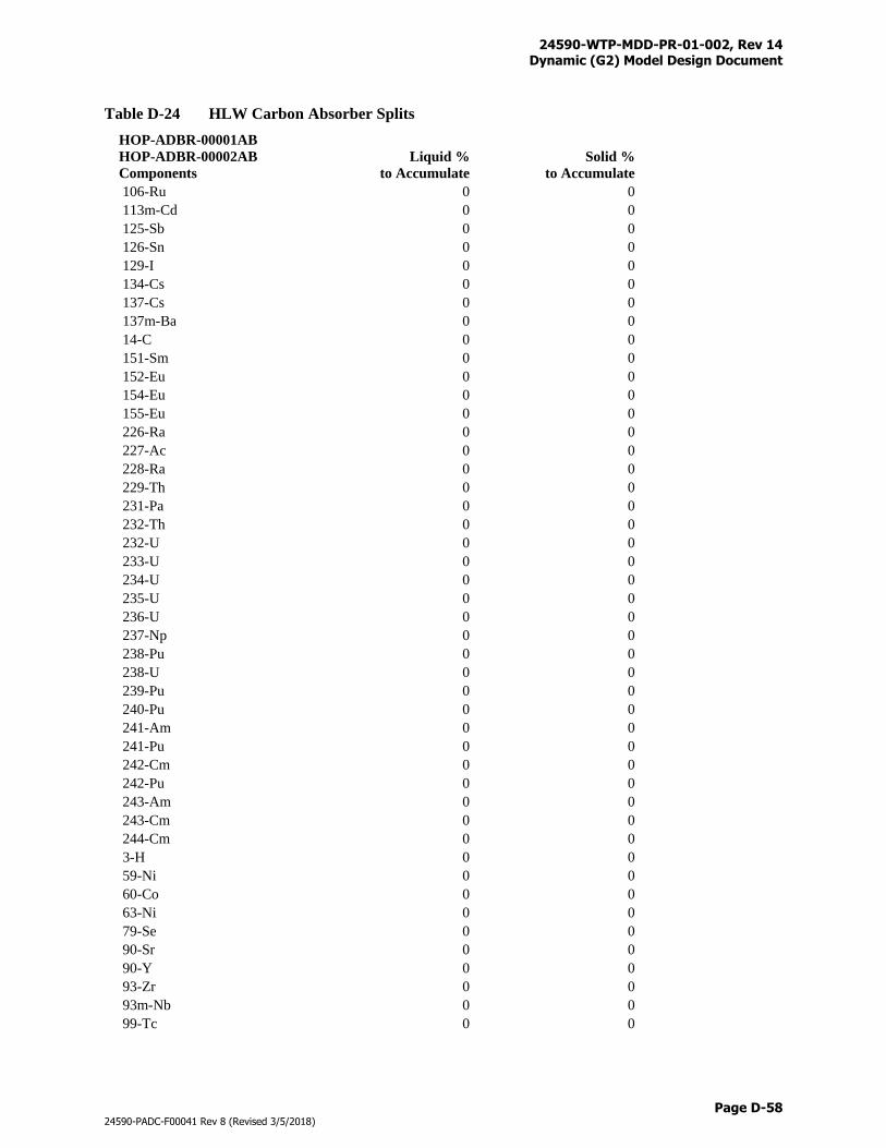
24590-WTP-MDD-PR-01-002, Rev 14 Dynamic (G2) Model Design Document
Page D-58
24590-PADC-F00041 Rev 8 (Revised 3/5/2018)
Table D-24 HLW Carbon Absorber Splits
HOP-ADBR-00001AB
HOP-ADBR-00002AB
Components
Liquid %
to Accumulate
Solid %
to Accumulate
106-Ru 0 0
113m-Cd 0 0
125-Sb 0 0
126-Sn 0 0
129-I 0 0
134-Cs 0 0
137-Cs 0 0
137m-Ba 0 0
14-C 0 0
151-Sm 0 0
152-Eu 0 0
154-Eu 0 0
155-Eu 0 0
226-Ra 0 0
227-Ac 0 0
228-Ra 0 0
229-Th 0 0
231-Pa 0 0
232-Th 0 0
232-U 0 0
233-U 0 0
234-U 0 0
235-U 0 0
236-U 0 0
237-Np 0 0
238-Pu 0 0
238-U 0 0
239-Pu 0 0
240-Pu 0 0
241-Am 0 0
241-Pu 0 0
242-Cm 0 0
242-Pu 0 0
243-Am 0 0
243-Cm 0 0
244-Cm 0 0
3-H 0 0
59-Ni 0 0
60-Co 0 0
63-Ni 0 0
79-Se 0 0
90-Sr 0 0
90-Y 0 0
93-Zr 0 0
93m-Nb 0 0
99-Tc 0 0
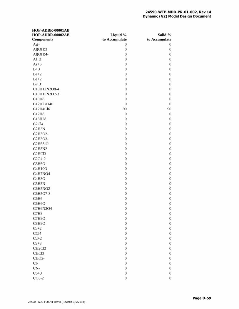
24590-WTP-MDD-PR-01-002, Rev 14 Dynamic (G2) Model Design Document
Page D-59
24590-PADC-F00041 Rev 8 (Revised 3/5/2018)
HOP-ADBR-00001AB
HOP-ADBR-00002AB
Components
Liquid %
to Accumulate
Solid %
to Accumulate
Ag+ 0 0
Al(OH)3 0 0
Al(OH)4- 0 0
Al+3 0 0
As+5 0 0
B+3 0 0
Ba+2 0 0
Be+2 0 0
Bi+3 0 0
C10H12N2O8-4 0 0
C10H15N2O7-3 0 0
C10H8 0 0
C12H27O4P 0 0
C12H4Cl6 90 90
C12H8 0 0
C13H28 0 0
C2Cl4 0 0
C2H3N 0 0
C2H3O2- 0 0
C2H3O3- 0 0
C2H6SiO 0 0
C2H8N2 0 0
C2HCl3 0 0
C2O4-2 0 0
C3H6O 0 0
C4H10O 0 0
C4H7NO4 0 0
C4H8O 0 0
C5H5N 0 0
C6H5NO2 0 0
C6H5O7-3 0 0
C6H6 0 0
C6H6O 0 0
C7H6N2O4 0 0
C7H8 0 0
C7H8O 0 0
C8H8O 0 0
Ca+2 0 0
CCl4 0 0
Cd+2 0 0
Ce+3 0 0
CH2Cl2 0 0
CHCl3 0 0
CHO2- 0 0
Cl- 0 0
CN- 0 0
Co+3 0 0
CO3-2 0 0
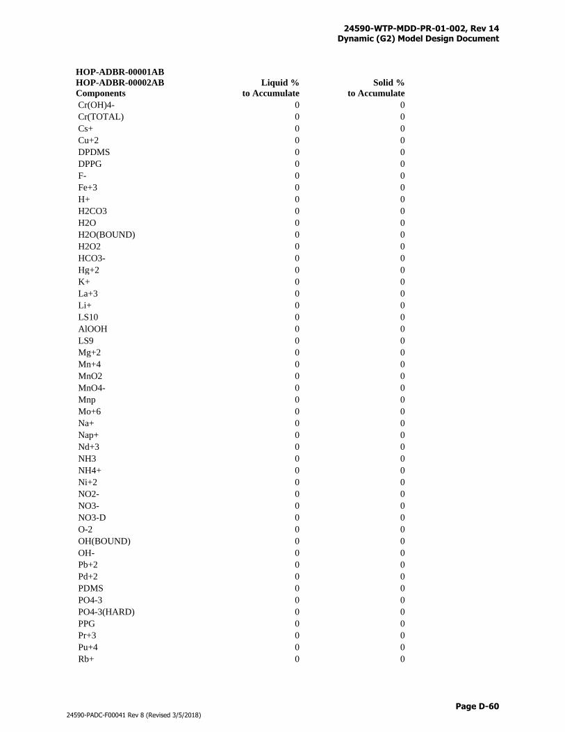
24590-WTP-MDD-PR-01-002, Rev 14 Dynamic (G2) Model Design Document
Page D-60
24590-PADC-F00041 Rev 8 (Revised 3/5/2018)
HOP-ADBR-00001AB
HOP-ADBR-00002AB
Components
Liquid %
to Accumulate
Solid %
to Accumulate
Cr(OH)4- 0 0
Cr(TOTAL) 0 0
Cs+ 0 0
Cu+2 0 0
DPDMS 0 0
DPPG 0 0
F- 0 0
Fe+3 0 0
H+ 0 0
H2CO3 0 0
H2O 0 0
H2O(BOUND) 0 0
H2O2 0 0
HCO3- 0 0
Hg+2 0 0
K+ 0 0
La+3 0 0
Li+ 0 0
LS10 0 0
AlOOH 0 0
LS9 0 0
Mg+2 0 0
Mn+4 0 0
MnO2 0 0
MnO4- 0 0
Mnp 0 0
Mo+6 0 0
Na+ 0 0
Nap+ 0 0
Nd+3 0 0
NH3 0 0
NH4+ 0 0
Ni+2 0 0
NO2- 0 0
NO3- 0 0
NO3-D 0 0
O-2 0 0
OH(BOUND) 0 0
OH- 0 0
Pb+2 0 0
Pd+2 0 0
PDMS 0 0
PO4-3 0 0
PO4-3(HARD) 0 0
PPG 0 0
Pr+3 0 0
Pu+4 0 0
Rb+ 0 0
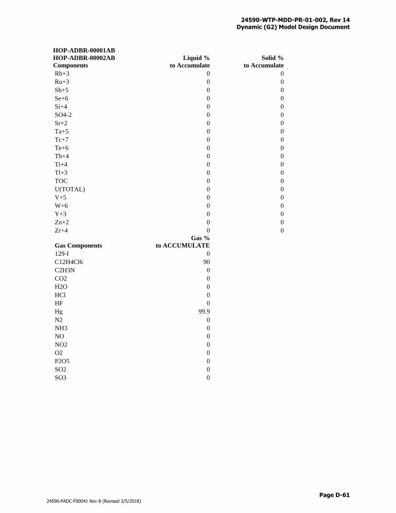
24590-WTP-MDD-PR-01-002, Rev 14 Dynamic (G2) Model Design Document
Page D-61
24590-PADC-F00041 Rev 8 (Revised 3/5/2018)
HOP-ADBR-00001AB
HOP-ADBR-00002AB
Components
Liquid %
to Accumulate
Solid %
to Accumulate
Rh+3 0 0
Ru+3 0 0
Sb+5 0 0
Se+6 0 0
Si+4 0 0
SO4-2 0 0
Sr+2 0 0
Ta+5 0 0
Tc+7 0 0
Te+6 0 0
Th+4 0 0
Ti+4 0 0
Tl+3 0 0
TOC 0 0
U(TOTAL) 0 0
V+5 0 0
W+6 0 0
Y+3 0 0
Zn+2 0 0
Zr+4 0 0
Gas Components
Gas %
to ACCUMULATE
129-I 0
C12H4Cl6 90
C2H3N 0
CO2 0
H2O 0
HCl 0
HF 0
Hg 99.9
N2 0
NH3 0
NO 0
NO2 0
O2 0
P2O5 0
SO2 0
SO3 0
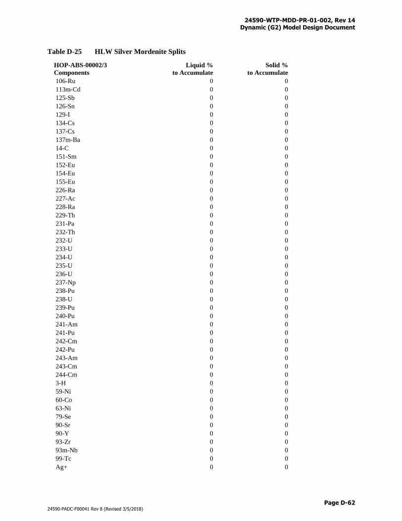
24590-WTP-MDD-PR-01-002, Rev 14 Dynamic (G2) Model Design Document
Page D-62
24590-PADC-F00041 Rev 8 (Revised 3/5/2018)
Table D-25 HLW Silver Mordenite Splits
HOP-ABS-00002/3
Components
Liquid %
to Accumulate
Solid %
to Accumulate
106-Ru 0 0
113m-Cd 0 0
125-Sb 0 0
126-Sn 0 0
129-I 0 0
134-Cs 0 0
137-Cs 0 0
137m-Ba 0 0
14-C 0 0
151-Sm 0 0
152-Eu 0 0
154-Eu 0 0
155-Eu 0 0
226-Ra 0 0
227-Ac 0 0
228-Ra 0 0
229-Th 0 0
231-Pa 0 0
232-Th 0 0
232-U 0 0
233-U 0 0
234-U 0 0
235-U 0 0
236-U 0 0
237-Np 0 0
238-Pu 0 0
238-U 0 0
239-Pu 0 0
240-Pu 0 0
241-Am 0 0
241-Pu 0 0
242-Cm 0 0
242-Pu 0 0
243-Am 0 0
243-Cm 0 0
244-Cm 0 0
3-H 0 0
59-Ni 0 0
60-Co 0 0
63-Ni 0 0
79-Se 0 0
90-Sr 0 0
90-Y 0 0
93-Zr 0 0
93m-Nb 0 0
99-Tc 0 0
Ag+ 0 0
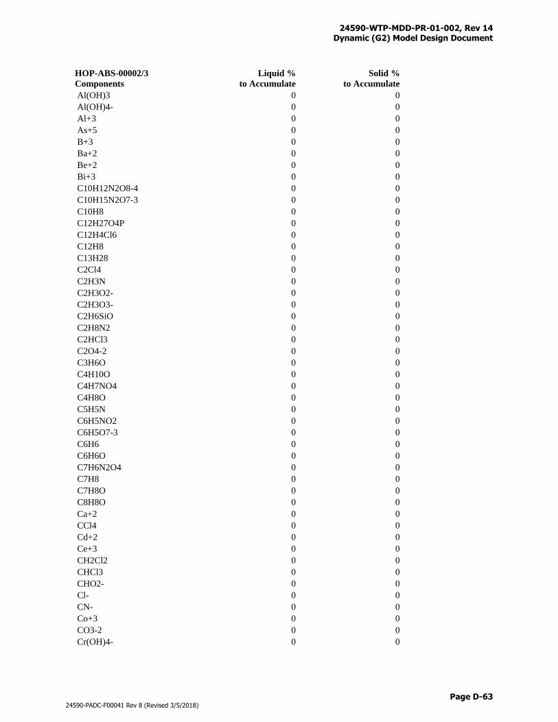
24590-WTP-MDD-PR-01-002, Rev 14 Dynamic (G2) Model Design Document
Page D-63
24590-PADC-F00041 Rev 8 (Revised 3/5/2018)
HOP-ABS-00002/3
Components
Liquid %
to Accumulate
Solid %
to Accumulate
Al(OH)3 0 0
Al(OH)4- 0 0
Al+3 0 0
As+5 0 0
B+3 0 0
Ba+2 0 0
Be+2 0 0
Bi+3 0 0
C10H12N2O8-4 0 0
C10H15N2O7-3 0 0
C10H8 0 0
C12H27O4P 0 0
C12H4Cl6 0 0
C12H8 0 0
C13H28 0 0
C2Cl4 0 0
C2H3N 0 0
C2H3O2- 0 0
C2H3O3- 0 0
C2H6SiO 0 0
C2H8N2 0 0
C2HCl3 0 0
C2O4-2 0 0
C3H6O 0 0
C4H10O 0 0
C4H7NO4 0 0
C4H8O 0 0
C5H5N 0 0
C6H5NO2 0 0
C6H5O7-3 0 0
C6H6 0 0
C6H6O 0 0
C7H6N2O4 0 0
C7H8 0 0
C7H8O 0 0
C8H8O 0 0
Ca+2 0 0
CCl4 0 0
Cd+2 0 0
Ce+3 0 0
CH2Cl2 0 0
CHCl3 0 0
CHO2- 0 0
Cl- 0 0
CN- 0 0
Co+3 0 0
CO3-2 0 0
Cr(OH)4- 0 0
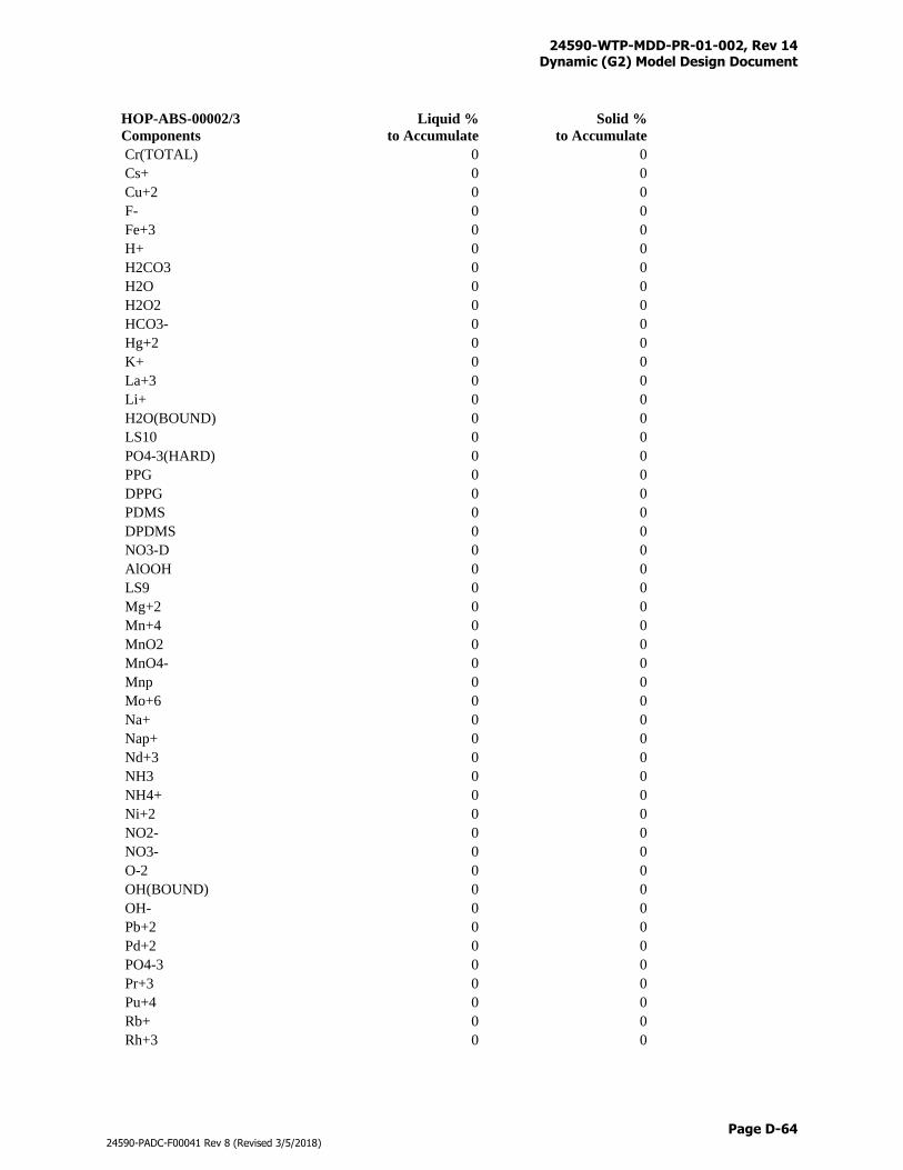
24590-WTP-MDD-PR-01-002, Rev 14 Dynamic (G2) Model Design Document
Page D-64
24590-PADC-F00041 Rev 8 (Revised 3/5/2018)
HOP-ABS-00002/3
Components
Liquid %
to Accumulate
Solid %
to Accumulate
Cr(TOTAL) 0 0
Cs+ 0 0
Cu+2 0 0
F- 0 0
Fe+3 0 0
H+ 0 0
H2CO3 0 0
H2O 0 0
H2O2 0 0
HCO3- 0 0
Hg+2 0 0
K+ 0 0
La+3 0 0
Li+ 0 0
H2O(BOUND) 0 0
LS10 0 0
PO4-3(HARD) 0 0
PPG 0 0
DPPG 0 0
PDMS 0 0
DPDMS 0 0
NO3-D 0 0
AlOOH 0 0
LS9 0 0
Mg+2 0 0
Mn+4 0 0
MnO2 0 0
MnO4- 0 0
Mnp 0 0
Mo+6 0 0
Na+ 0 0
Nap+ 0 0
Nd+3 0 0
NH3 0 0
NH4+ 0 0
Ni+2 0 0
NO2- 0 0
NO3- 0 0
O-2 0 0
OH(BOUND) 0 0
OH- 0 0
Pb+2 0 0
Pd+2 0 0
PO4-3 0 0
Pr+3 0 0
Pu+4 0 0
Rb+ 0 0
Rh+3 0 0
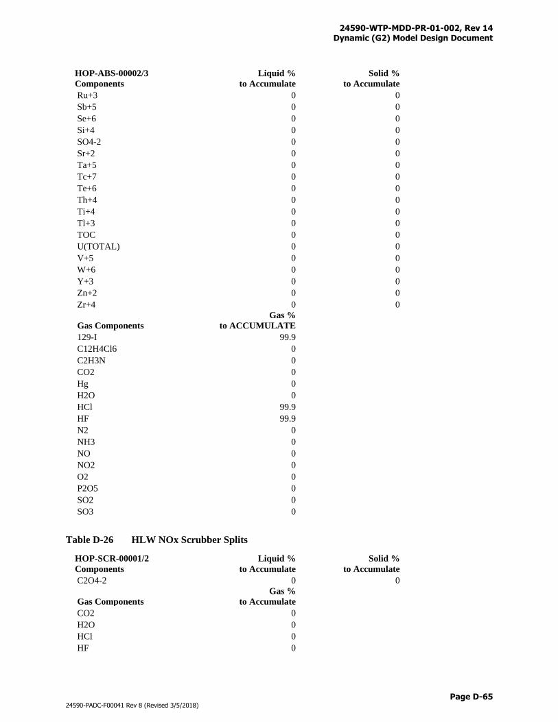
24590-WTP-MDD-PR-01-002, Rev 14 Dynamic (G2) Model Design Document
Page D-65
24590-PADC-F00041 Rev 8 (Revised 3/5/2018)
HOP-ABS-00002/3
Components
Liquid %
to Accumulate
Solid %
to Accumulate
Ru+3 0 0
Sb+5 0 0
Se+6 0 0
Si+4 0 0
SO4-2 0 0
Sr+2 0 0
Ta+5 0 0
Tc+7 0 0
Te+6 0 0
Th+4 0 0
Ti+4 0 0
Tl+3 0 0
TOC 0 0
U(TOTAL) 0 0
V+5 0 0
W+6 0 0
Y+3 0 0
Zn+2 0 0
Zr+4 0 0
Gas Components
Gas %
to ACCUMULATE
129-I 99.9
C12H4Cl6 0
C2H3N 0
CO2 0
Hg 0
H2O 0
HCl 99.9
HF 99.9
N2 0
NH3 0
NO 0
NO2 0
O2 0
P2O5 0
SO2 0
SO3 0
Table D-26 HLW NOx Scrubber Splits
HOP-SCR-00001/2
Components
Liquid %
to Accumulate
Solid %
to Accumulate
C2O4-2 0 0
Gas Components
Gas %
to Accumulate
CO2 0
H2O 0
HCl 0
HF 0
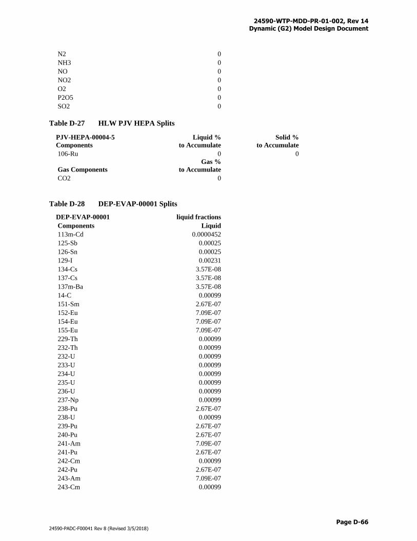
24590-WTP-MDD-PR-01-002, Rev 14 Dynamic (G2) Model Design Document
Page D-66
24590-PADC-F00041 Rev 8 (Revised 3/5/2018)
N2 0
NH3 0
NO 0
NO2 0
O2 0
P2O5 0
SO2 0
Table D-27 HLW PJV HEPA Splits
PJV-HEPA-00004-5
Components
Liquid %
to Accumulate
Solid %
to Accumulate
106-Ru 0 0
Gas Components
Gas %
to Accumulate
CO2 0
Table D-28 DEP-EVAP-00001 Splits
DEP-EVAP-00001 liquid fractions
Components Liquid
113m-Cd 0.0000452
125-Sb 0.00025
126-Sn 0.00025
129-I 0.00231
134-Cs 3.57E-08
137-Cs 3.57E-08
137m-Ba 3.57E-08
14-C 0.00099
151-Sm 2.67E-07
152-Eu 7.09E-07
154-Eu 7.09E-07
155-Eu 7.09E-07
229-Th 0.00099
232-Th 0.00099
232-U 0.00099
233-U 0.00099
234-U 0.00099
235-U 0.00099
236-U 0.00099
237-Np 0.00099
238-Pu 2.67E-07
238-U 0.00099
239-Pu 2.67E-07
240-Pu 2.67E-07
241-Am 7.09E-07
241-Pu 2.67E-07
242-Cm 0.00099
242-Pu 2.67E-07
243-Am 7.09E-07
243-Cm 0.00099
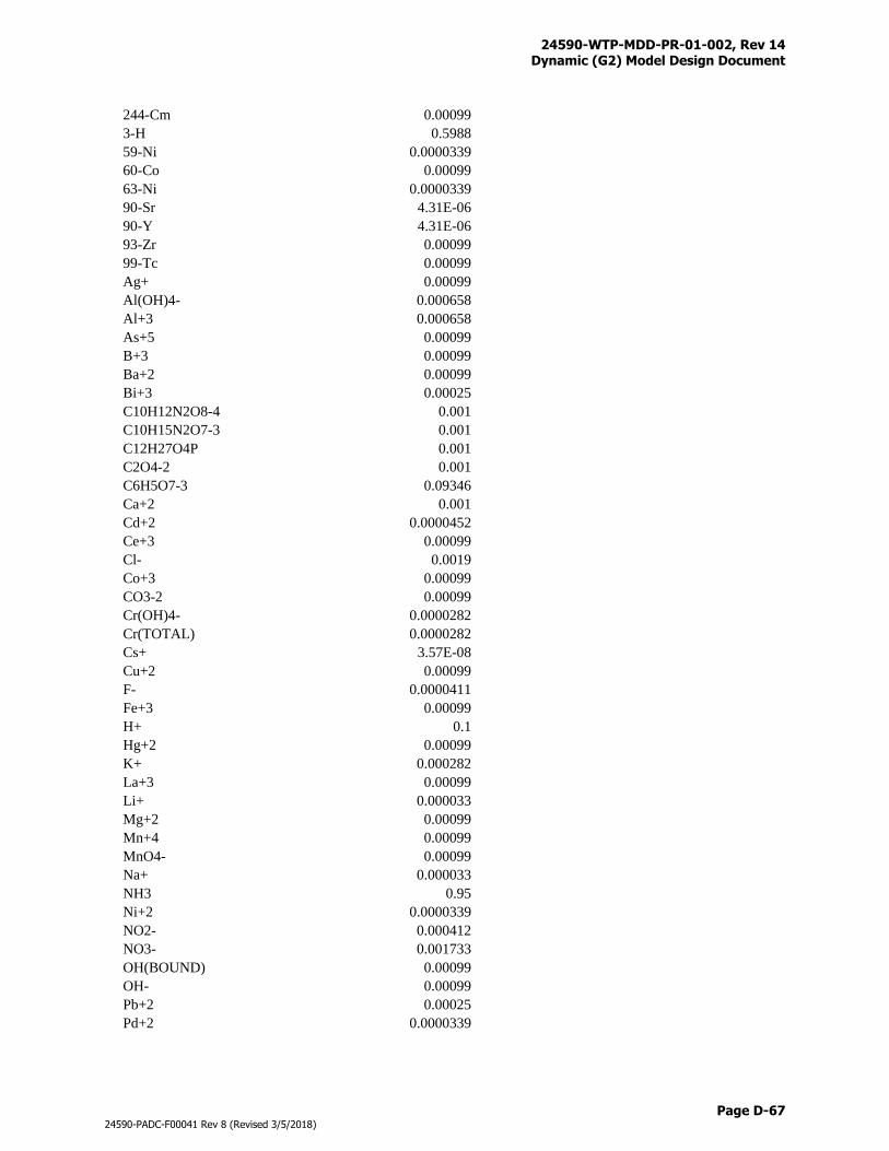
24590-WTP-MDD-PR-01-002, Rev 14 Dynamic (G2) Model Design Document
Page D-67
24590-PADC-F00041 Rev 8 (Revised 3/5/2018)
244-Cm 0.00099
3-H 0.5988
59-Ni 0.0000339
60-Co 0.00099
63-Ni 0.0000339
90-Sr 4.31E-06
90-Y 4.31E-06
93-Zr 0.00099
99-Tc 0.00099
Ag+ 0.00099
Al(OH)4- 0.000658
Al+3 0.000658
As+5 0.00099
B+3 0.00099
Ba+2 0.00099
Bi+3 0.00025
C10H12N2O8-4 0.001
C10H15N2O7-3 0.001
C12H27O4P 0.001
C2O4-2 0.001
C6H5O7-3 0.09346
Ca+2 0.001
Cd+2 0.0000452
Ce+3 0.00099
Cl- 0.0019
Co+3 0.00099
CO3-2 0.00099
Cr(OH)4- 0.0000282
Cr(TOTAL) 0.0000282
Cs+ 3.57E-08
Cu+2 0.00099
F- 0.0000411
Fe+3 0.00099
H+ 0.1
Hg+2 0.00099
K+ 0.000282
La+3 0.00099
Li+ 0.000033
Mg+2 0.00099
Mn+4 0.00099
MnO4- 0.00099
Na+ 0.000033
NH3 0.95
Ni+2 0.0000339
NO2- 0.000412
NO3- 0.001733
OH(BOUND) 0.00099
OH- 0.00099
Pb+2 0.00025
Pd+2 0.0000339
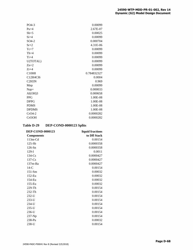
24590-WTP-MDD-PR-01-002, Rev 14 Dynamic (G2) Model Design Document
Page D-68
24590-PADC-F00041 Rev 8 (Revised 3/5/2018)
PO4-3 0.00099
Pu+4 2.67E-07
Sb+5 0.00025
Si+4 0.00099
SO4-2 0.000704
Sr+2 4.31E-06
Tc+7 0.00099
Th+4 0.00099
Ti+4 0.00099
U(TOTAL) 0.00099
Zn+2 0.00099
Zr+4 0.00099
C10H8 0.784832327
C12H4Cl6 0.0004
C2H3N 0.969
Mnp 0.00099
Nap+ 0.000033
Al(OH)3 0.000658
PPG 1.00E-08
DPPG 1.00E-08
PDMS 1.00E-08
DPDMS 1.00E-08
CrO4-2 0.0000282
CrOOH 0.0000282
Table D-29 DEP-COND-0000123 Splits
DEP-COND-0000123 liquid fractions
Components to Dfl Stack
113m-Cd 0.00154
125-Sb 0.0000358
126-Sn 0.0000358
129-I 0.0011
134-Cs 0.0000427
137-Cs 0.0000427
137m-Ba 0.0000427
14-C 0.00154
151-Sm 0.00032
152-Eu 0.00032
154-Eu 0.00032
155-Eu 0.00032
229-Th 0.00154
232-Th 0.00154
232-U 0.00154
233-U 0.00154
234-U 0.00154
235-U 0.00154
236-U 0.00154
237-Np 0.00154
238-Pu 0.00032
238-U 0.00154
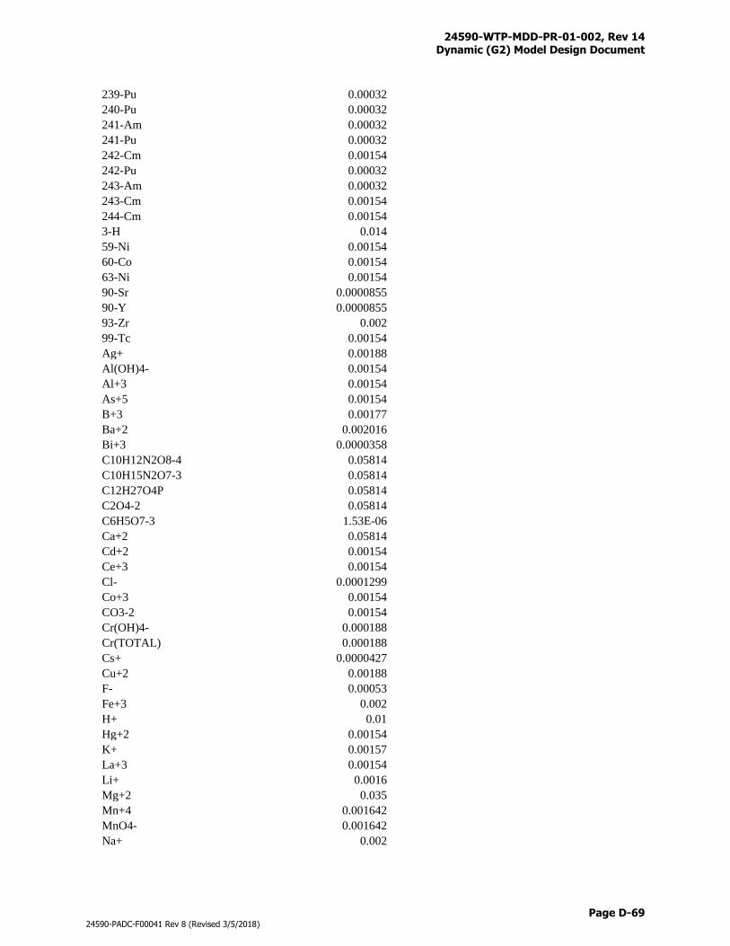
24590-WTP-MDD-PR-01-002, Rev 14 Dynamic (G2) Model Design Document
Page D-69
24590-PADC-F00041 Rev 8 (Revised 3/5/2018)
239-Pu 0.00032
240-Pu 0.00032
241-Am 0.00032
241-Pu 0.00032
242-Cm 0.00154
242-Pu 0.00032
243-Am 0.00032
243-Cm 0.00154
244-Cm 0.00154
3-H 0.014
59-Ni 0.00154
60-Co 0.00154
63-Ni 0.00154
90-Sr 0.0000855
90-Y 0.0000855
93-Zr 0.002
99-Tc 0.00154
Ag+ 0.00188
Al(OH)4- 0.00154
Al+3 0.00154
As+5 0.00154
B+3 0.00177
Ba+2 0.002016
Bi+3 0.0000358
C10H12N2O8-4 0.05814
C10H15N2O7-3 0.05814
C12H27O4P 0.05814
C2O4-2 0.05814
C6H5O7-3 1.53E-06
Ca+2 0.05814
Cd+2 0.00154
Ce+3 0.00154
Cl- 0.0001299
Co+3 0.00154
CO3-2 0.00154
Cr(OH)4- 0.000188
Cr(TOTAL) 0.000188
Cs+ 0.0000427
Cu+2 0.00188
F- 0.00053
Fe+3 0.002
H+ 0.01
Hg+2 0.00154
K+ 0.00157
La+3 0.00154
Li+ 0.0016
Mg+2 0.035
Mn+4 0.001642
MnO4- 0.001642
Na+ 0.002
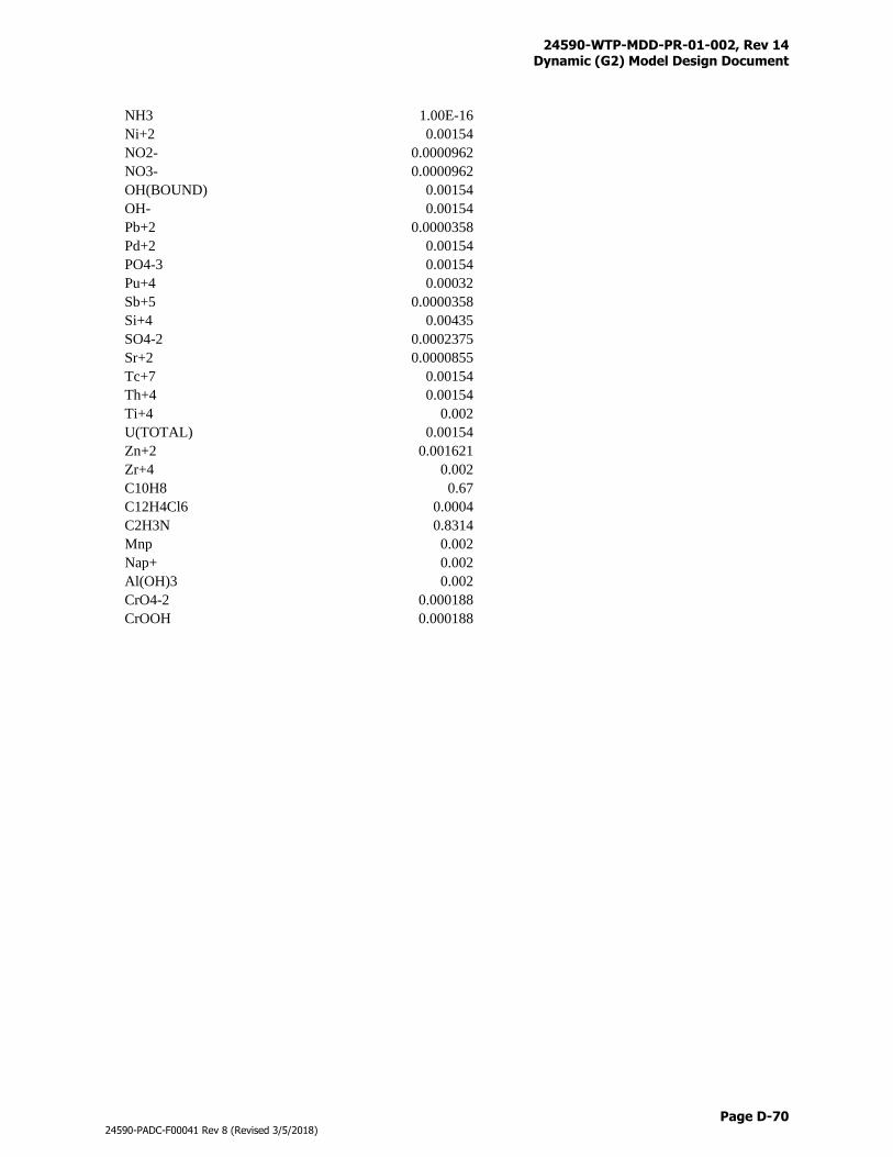
24590-WTP-MDD-PR-01-002, Rev 14 Dynamic (G2) Model Design Document
Page D-70
24590-PADC-F00041 Rev 8 (Revised 3/5/2018)
NH3 1.00E-16
Ni+2 0.00154
NO2- 0.0000962
NO3- 0.0000962
OH(BOUND) 0.00154
OH- 0.00154
Pb+2 0.0000358
Pd+2 0.00154
PO4-3 0.00154
Pu+4 0.00032
Sb+5 0.0000358
Si+4 0.00435
SO4-2 0.0002375
Sr+2 0.0000855
Tc+7 0.00154
Th+4 0.00154
Ti+4 0.002
U(TOTAL) 0.00154
Zn+2 0.001621
Zr+4 0.002
C10H8 0.67
C12H4Cl6 0.0004
C2H3N 0.8314
Mnp 0.002
Nap+ 0.002
Al(OH)3 0.002
CrO4-2 0.000188
CrOOH 0.000188
24590-WTP-MDD-PR-01-002, Rev 14 Dynamic (G2) Model Design Document
Page E-i
24590-PADC-F00041 Rev 8 (Revised 3/5/2018)
Appendix E
Vessel Parameter Table
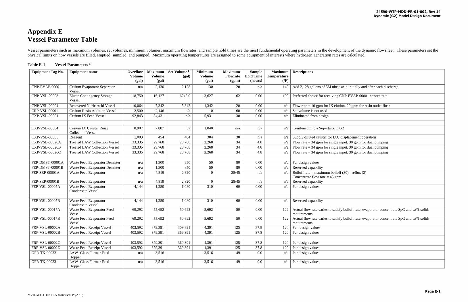
24590-WTP-MDD-PR-01-002, Rev 14 Dynamic (G2) Model Design Document
Page E-1
24590-PADC-F00041 Rev 8 (Revised 3/5/2018)
Appendix E
Vessel Parameter Table
Vessel parameters such as maximum volumes, set volumes, minimum volumes, maximum flowrates, and sample hold times are the most fundamental operating parameters in the development of the dynamic flowsheet. These parameters set the
physical limits on how vessels are filled, emptied, sampled, and pumped. Maximum operating temperatures are assigned to some equipment of interests where hydrogen generation rates are calculated.
Table E-1 Vessel Parameters a)
Equipment Tag No. Equipment name Overflow
Volume
(gal)
Maximum
Volume
(gal)
Set Volume b)
(gal)
Minimum
Volume
(gal)
Maximum
Flowrate
(gpm)
Sample
Hold Time
(hours)
Maximum
Temperature
(oF)
Descriptions
CNP-EVAP-00001 Cesium Evaporator Separator
Vessel
n/a 2,130 2,128 130 20 n/a 140 Add 2,128 gallons of 5M nitric acid initially and after each discharge
CNP-VSL-00003 Eluate Contingency Storage
Vessel
18,750 16,127 6242.0
3,627 62 0.00 190 Preferred choice for receiving CNP-EVAP-00001 concentrate
CNP-VSL-00004 Recovered Nitric Acid Vessel 10,064 7,342 5,342 1,342 20 0.00 n/a Flow rate = 10 gpm for IX elution, 20 gpm for resin outlet flush
CRP-VSL-00001 Cesium Resin Addition Vessel 2,500 2,146 n/a 0 60 0.00 n/a Set volume is not used
CXP-VSL-00001 Cesium IX Feed Vessel 92,843 84,431 n/a 5,931 30 0.00 n/a Eliminated from design
CXP-VSL-00004 Cesium IX Caustic Rinse
Collection Vessel
8,907 7,807 n/a 1,840 n/a n/a n/a Combined into a Supertank in G2
CXP-VSL-00005 Reagent 1,003 454 404 304 30 n/a n/a Supply diluted caustic for IXC displacement operation
CXP-VSL-00026A Treated LAW Collection Vessel 33,335 29,768 28,768 2,268 34 4.8 n/a Flow rate = 34 gpm for single input, 30 gpm for dual pumping
CXP-VSL-00026B Treated LAW Collection Vessel 33,335 29,768 28,768 2,268 34 4.8 n/a Flow rate = 34 gpm for single input, 30 gpm for dual pumping
CXP-VSL-00026C Treated LAW Collection Vessel 33,335 29,768 28,768 2,268 34 4.8 n/a Flow rate = 34 gpm for single input, 30 gpm for dual pumping
FEP-DMST-00001A Waste Feed Evaporator Demister n/a 1,300 850 50 80 0.00 n/a Per design values
FEP-DMST-00001B Waste Feed Evaporator Demister n/a 1,300 850 50 80 0.00 n/a Reserved capability
FEP-SEP-00001A Waste Feed Evaporator n/a 4,819 2,820 0 28/45 n/a n/a Boiloff rate = maximum boiloff (30) - reflux (2)
Concentrate flow rate = 45 gpm
FEP-SEP-00001B Waste Feed Evaporator n/a 4,819 2,820 0 28/45 n/a n/a Reserved capability
FEP-VSL-00005A Waste Feed Evaporator
Condensate Vessel
4,144 1,280 1,080 310 60 0.00 n/a Per design values
FEP-VSL-00005B Waste Feed Evaporator
Condensate Vessel
4,144 1,280 1,080 310 60 0.00 n/a Reserved capability
FEP-VSL-00017A Waste Feed Evaporator Feed
Vessel
69,292 55,692 50,692 5,692 50 0.00 122 Actual flow rate varies to satisfy boiloff rate, evaporator concentrate SpG and wt% solids
requirements
FEP-VSL-00017B Waste Feed Evaporator Feed
Vessel
69,292 55,692 50,692 5,692 50 0.00 122 Actual flow rate varies to satisfy boiloff rate, evaporator concentrate SpG and wt% solids
requirements
FRP-VSL-00002A Waste Feed Receipt Vessel 403,592 379,391 309,391 4,391 125 37.8 120 Per design values
FRP-VSL-00002B Waste Feed Receipt Vessel 403,592 379,391 369,391 4,391 125 37.8 120 Per design values
FRP-VSL-00002C Waste Feed Receipt Vessel 403,592 379,391 369,391 4,391 125 37.8 120 Per design values
FRP-VSL-00002D Waste Feed Receipt Vessel 403,592 379,391 369,391 4,391 125 37.8 120 Per design values
GFR-TK-00022 LAW Glass Former Feed
Hopper
n/a 3,516 3,516 49 0.0 n/a Per design values
GFR-TK-00023 LAW Glass Former Feed
Hopper n/a 3,516 3,516 49 0.0 n/a Per design values
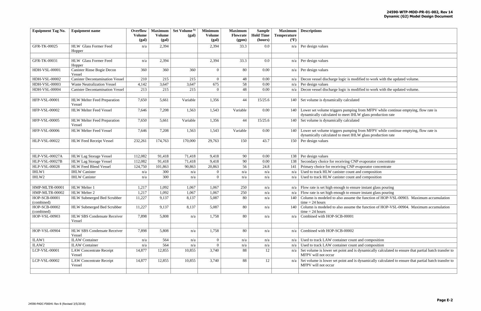
24590-WTP-MDD-PR-01-002, Rev 14 Dynamic (G2) Model Design Document
Page E-2
24590-PADC-F00041 Rev 8 (Revised 3/5/2018)
Equipment Tag No. Equipment name Overflow
Volume
(gal)
Maximum
Volume
(gal)
Set Volume b)
(gal)
Minimum
Volume
(gal)
Maximum
Flowrate
(gpm)
Sample
Hold Time
(hours)
Maximum
Temperature
(oF)
Descriptions
GFR-TK-00025 HLW Glass Former Feed
Hopper n/a 2,394 2,394 33.3 0.0 n/a Per design values
GFR-TK-00031 HLW Glass Former Feed
Hopper n/a 2,394 2,394 33.3 0.0 n/a Per design values
HDH-VSL-00001 Canister Rinse Bogie Decon
Vessel
360 360 360 0 80 0.00 n/a Per design values
HDH-VSL-00002 Canister Decontamination Vessel 210 215 215 0 48 0.00 n/a Decon vessel discharge logic is modified to work with the updated volume.
HDH-VSL-00003 Waste Neutralization Vessel 4,142 3,647 3,647 675 58 0.00 n/a Per design values
HDH-VSL-00004 Canister Decontamination Vessel 213 215 215 0 48 0.00 n/a Decon vessel discharge logic is modified to work with the updated volume.
HFP-VSL-00001 HLW Melter Feed Preparation
Vessel
7,650 5,661 Variable 1,356 44 15/25.6 140 Set volume is dynamically calculated
HFP-VSL-00002 HLW Melter Feed Vessel 7,646 7,208 1,563 1,543 Variable 0.00 140 Lower set volume triggers pumping from MFPV while continue emptying, flow rate is
dynamically calculated to meet IHLW glass production rate
HFP-VSL-00005 HLW Melter Feed Preparation
Vessel
7,650 5,661 Variable 1,356 44 15/25.6 140 Set volume is dynamically calculated
HFP-VSL-00006 HLW Melter Feed Vessel 7,646 7,208 1,563 1,543 Variable 0.00 140 Lower set volume triggers pumping from MFPV while continue emptying, flow rate is
dynamically calculated to meet IHLW glass production rate
HLP-VSL-00022 HLW Feed Receipt Vessel 232,261 174,763 170,000 29,763 150 43.7 150 Per design values
HLP-VSL-00027A HLW Lag Storage Vessel 112,082 91,418 71,418 9,418 90 0.00 138 Per design values
HLP-VSL-00027B HLW Lag Storage Vessel 112,082 91,418 71,418 9,418 90 0.00 138 Secondary choice for receiving CNP evaporator concentrate
HLP-VSL-00028 HLW Feed Blend Vessel 124,750 101,863 90,863 20,863 56 24.8 141 Primary choice for receiving CNP evaporator concentrate
IHLW1 IHLW Canister n/a 300 n/a 0 n/a n/a n/a Used to track HLW canister count and composition
IHLW2 IHLW Canister n/a 300 n/a 0 n/a n/a n/a Used to track HLW canister count and composition
HMP-MLTR-00001 HLW Melter 1 1,217 1,092 1,067 1,067 250 n/a n/a Flow rate is set high enough to ensure instant glass pouring
HMP-MLTR-00002 HLW Melter 2 1,217 1,092 1,067 1,067 250 n/a n/a Flow rate is set high enough to ensure instant glass pouring
HOP-SCB-00001
(combined)
HLW Submerged Bed Scrubber 11,227 9,137 8,137 5,087 80 n/a 140 Column is modeled to also assume the function of HOP-VSL-00903. Maximum accumulation
time = 24 hours
HOP-SCB-00002
(combined)
HLW Submerged Bed Scrubber 11,227 9,137 8,137 5,087 80 n/a 140 Column is modeled to also assume the function of HOP-VSL-00904. Maximum accumulation
time = 24 hours
HOP-VSL-00903 HLW SBS Condensate Receiver
Vessel
7,898 5,808 n/a 1,758 80 n/a n/a Combined with HOP-SCB-00001
HOP-VSL-00904 HLW SBS Condensate Receiver
Vessel
7,898 5,808 n/a 1,758 80 n/a n/a Combined with HOP-SCB-00002
ILAW1 ILAW Container n/a 564 n/a 0 n/a n/a n/a Used to track LAW container count and composition
ILAW2 ILAW Container n/a 564 n/a 0 n/a n/a n/a Used to track LAW container count and composition
LCP-VSL-00001 LAW Concentrate Receipt
Vessel
14,877 12,855 10,855 3,740 88 12 n/a Set volume is lower set point and is dynamically calculated to ensure that partial batch transfer to
MFPV will not occur
LCP-VSL-00002 LAW Concentrate Receipt
Vessel
14,877 12,855 10,855 3,740 88 12 n/a Set volume is lower set point and is dynamically calculated to ensure that partial batch transfer to
MFPV will not occur
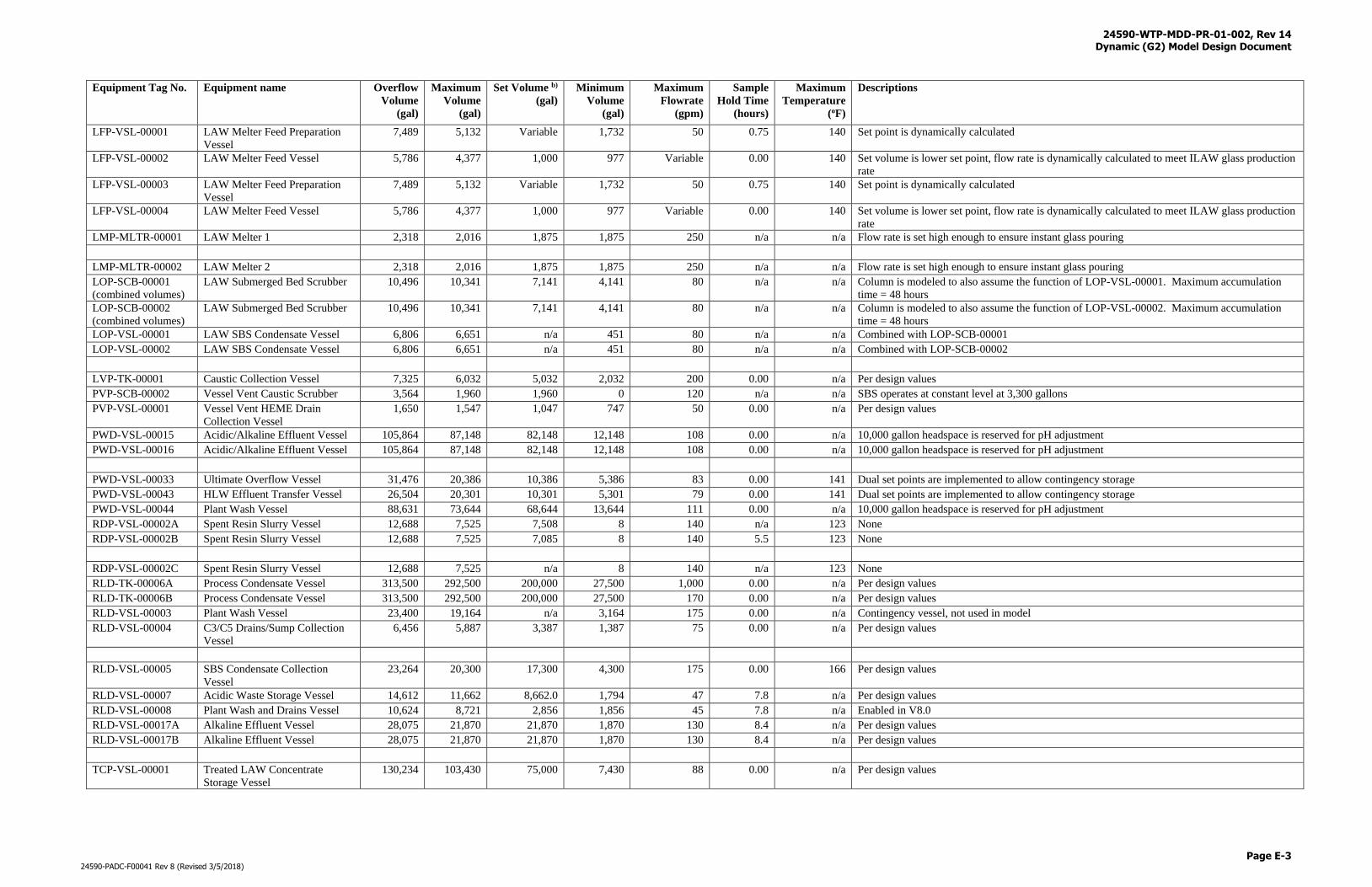
24590-WTP-MDD-PR-01-002, Rev 14 Dynamic (G2) Model Design Document
Page E-3
24590-PADC-F00041 Rev 8 (Revised 3/5/2018)
Equipment Tag No. Equipment name Overflow
Volume
(gal)
Maximum
Volume
(gal)
Set Volume b)
(gal)
Minimum
Volume
(gal)
Maximum
Flowrate
(gpm)
Sample
Hold Time
(hours)
Maximum
Temperature
(oF)
Descriptions
LFP-VSL-00001 LAW Melter Feed Preparation
Vessel
7,489 5,132 Variable 1,732 50 0.75 140 Set point is dynamically calculated
LFP-VSL-00002 LAW Melter Feed Vessel 5,786 4,377 1,000 977 Variable 0.00 140 Set volume is lower set point, flow rate is dynamically calculated to meet ILAW glass production
rate
LFP-VSL-00003 LAW Melter Feed Preparation
Vessel
7,489 5,132 Variable 1,732 50 0.75 140 Set point is dynamically calculated
LFP-VSL-00004 LAW Melter Feed Vessel 5,786 4,377 1,000 977 Variable 0.00 140 Set volume is lower set point, flow rate is dynamically calculated to meet ILAW glass production
rate
LMP-MLTR-00001 LAW Melter 1 2,318 2,016 1,875 1,875 250 n/a n/a Flow rate is set high enough to ensure instant glass pouring
LMP-MLTR-00002 LAW Melter 2 2,318 2,016 1,875 1,875 250 n/a n/a Flow rate is set high enough to ensure instant glass pouring
LOP-SCB-00001
(combined volumes)
LAW Submerged Bed Scrubber 10,496 10,341 7,141 4,141 80 n/a n/a Column is modeled to also assume the function of LOP-VSL-00001. Maximum accumulation
time = 48 hours
LOP-SCB-00002
(combined volumes)
LAW Submerged Bed Scrubber 10,496 10,341 7,141 4,141 80 n/a n/a Column is modeled to also assume the function of LOP-VSL-00002. Maximum accumulation
time = 48 hours
LOP-VSL-00001 LAW SBS Condensate Vessel 6,806 6,651 n/a 451 80 n/a n/a Combined with LOP-SCB-00001
LOP-VSL-00002 LAW SBS Condensate Vessel 6,806 6,651 n/a 451 80 n/a n/a Combined with LOP-SCB-00002
LVP-TK-00001 Caustic Collection Vessel 7,325 6,032 5,032 2,032 200 0.00 n/a Per design values
PVP-SCB-00002 Vessel Vent Caustic Scrubber 3,564 1,960 1,960 0 120 n/a n/a SBS operates at constant level at 3,300 gallons
PVP-VSL-00001 Vessel Vent HEME Drain
Collection Vessel
1,650 1,547 1,047 747 50 0.00 n/a Per design values
PWD-VSL-00015 Acidic/Alkaline Effluent Vessel 105,864 87,148 82,148 12,148 108 0.00 n/a 10,000 gallon headspace is reserved for pH adjustment
PWD-VSL-00016 Acidic/Alkaline Effluent Vessel 105,864 87,148 82,148 12,148 108 0.00 n/a 10,000 gallon headspace is reserved for pH adjustment
PWD-VSL-00033 Ultimate Overflow Vessel 31,476 20,386 10,386 5,386 83 0.00 141 Dual set points are implemented to allow contingency storage
PWD-VSL-00043 HLW Effluent Transfer Vessel 26,504 20,301 10,301 5,301 79 0.00 141 Dual set points are implemented to allow contingency storage
PWD-VSL-00044 Plant Wash Vessel 88,631 73,644 68,644 13,644 111 0.00 n/a 10,000 gallon headspace is reserved for pH adjustment
RDP-VSL-00002A Spent Resin Slurry Vessel 12,688 7,525 7,508 8 140 n/a 123 None
RDP-VSL-00002B Spent Resin Slurry Vessel 12,688 7,525 7,085 8 140 5.5 123 None
RDP-VSL-00002C Spent Resin Slurry Vessel 12,688 7,525 n/a 8 140 n/a 123 None
RLD-TK-00006A Process Condensate Vessel 313,500 292,500 200,000 27,500 1,000 0.00 n/a Per design values
RLD-TK-00006B Process Condensate Vessel 313,500 292,500 200,000 27,500 170 0.00 n/a Per design values
RLD-VSL-00003 Plant Wash Vessel 23,400 19,164 n/a 3,164 175 0.00 n/a Contingency vessel, not used in model
RLD-VSL-00004 C3/C5 Drains/Sump Collection
Vessel
6,456 5,887 3,387 1,387 75 0.00 n/a Per design values
RLD-VSL-00005 SBS Condensate Collection
Vessel
23,264 20,300 17,300 4,300 175 0.00 166 Per design values
RLD-VSL-00007 Acidic Waste Storage Vessel 14,612 11,662 8,662.0 1,794 47 7.8 n/a Per design values
RLD-VSL-00008 Plant Wash and Drains Vessel 10,624 8,721 2,856 1,856 45 7.8 n/a Enabled in V8.0
RLD-VSL-00017A Alkaline Effluent Vessel 28,075 21,870 21,870 1,870 130 8.4 n/a Per design values
RLD-VSL-00017B Alkaline Effluent Vessel 28,075 21,870 21,870 1,870 130 8.4 n/a Per design values
TCP-VSL-00001 Treated LAW Concentrate
Storage Vessel
130,234 103,430 75,000 7,430 88 0.00 n/a Per design values
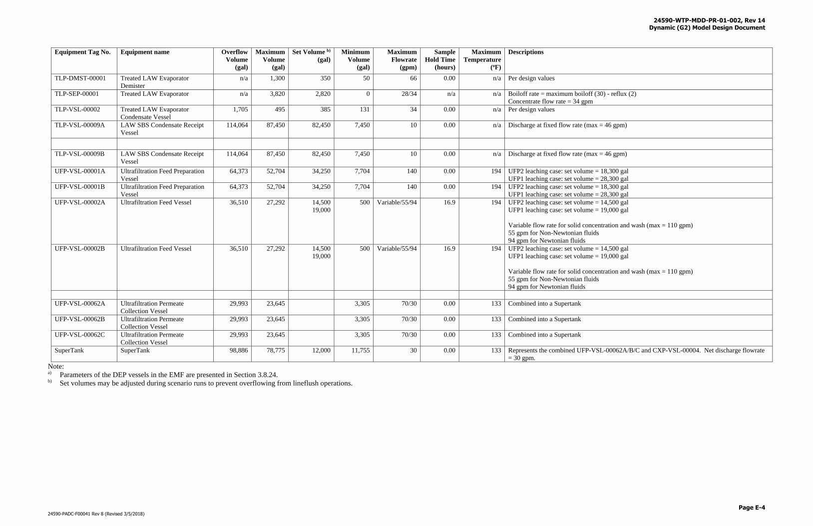
24590-WTP-MDD-PR-01-002, Rev 14 Dynamic (G2) Model Design Document
Page E-4
24590-PADC-F00041 Rev 8 (Revised 3/5/2018)
Equipment Tag No. Equipment name Overflow
Volume
(gal)
Maximum
Volume
(gal)
Set Volume b)
(gal)
Minimum
Volume
(gal)
Maximum
Flowrate
(gpm)
Sample
Hold Time
(hours)
Maximum
Temperature
(oF)
Descriptions
TLP-DMST-00001 Treated LAW Evaporator
Demister
n/a 1,300 350 50 66 0.00 n/a Per design values
TLP-SEP-00001 Treated LAW Evaporator n/a 3,820 2,820 0 28/34 n/a n/a Boiloff rate = maximum boiloff (30) - reflux (2)
Concentrate flow rate = 34 gpm
TLP-VSL-00002 Treated LAW Evaporator
Condensate Vessel
1,705 495 385 131 34 0.00 n/a Per design values
TLP-VSL-00009A LAW SBS Condensate Receipt
Vessel
114,064 87,450 82,450 7,450 10 0.00 n/a Discharge at fixed flow rate (max = 46 gpm)
TLP-VSL-00009B LAW SBS Condensate Receipt
Vessel
114,064 87,450 82,450 7,450 10 0.00 n/a Discharge at fixed flow rate (max = 46 gpm)
UFP-VSL-00001A Ultrafiltration Feed Preparation
Vessel
64,373 52,704 34,250 7,704 140 0.00 194 UFP2 leaching case: set volume = 18,300 gal
UFP1 leaching case: set volume = 28,300 gal
UFP-VSL-00001B Ultrafiltration Feed Preparation
Vessel
64,373 52,704 34,250 7,704 140 0.00 194 UFP2 leaching case: set volume = 18,300 gal
UFP1 leaching case: set volume = 28,300 gal
UFP-VSL-00002A Ultrafiltration Feed Vessel 36,510 27,292 14,500
19,000
500 Variable/55/94 16.9 194 UFP2 leaching case: set volume = 14,500 gal
UFP1 leaching case: set volume = 19,000 gal
Variable flow rate for solid concentration and wash (max = 110 gpm)
55 gpm for Non-Newtonian fluids
94 gpm for Newtonian fluids
UFP-VSL-00002B Ultrafiltration Feed Vessel 36,510 27,292 14,500
19,000
500 Variable/55/94 16.9 194 UFP2 leaching case: set volume = 14,500 gal
UFP1 leaching case: set volume = 19,000 gal
Variable flow rate for solid concentration and wash (max = 110 gpm)
55 gpm for Non-Newtonian fluids
94 gpm for Newtonian fluids
UFP-VSL-00062A Ultrafiltration Permeate
Collection Vessel
29,993 23,645 3,305 70/30 0.00 133 Combined into a Supertank
UFP-VSL-00062B Ultrafiltration Permeate
Collection Vessel
29,993 23,645 3,305 70/30 0.00 133 Combined into a Supertank
UFP-VSL-00062C Ultrafiltration Permeate
Collection Vessel
29,993 23,645 3,305 70/30 0.00 133 Combined into a Supertank
SuperTank SuperTank 98,886 78,775 12,000 11,755 30 0.00 133 Represents the combined UFP-VSL-00062A/B/C and CXP-VSL-00004. Net discharge flowrate
= 30 gpm.
Note: a) Parameters of the DEP vessels in the EMF are presented in Section 3.8.24. b) Set volumes may be adjusted during scenario runs to prevent overflowing from lineflush operations.
24590-WTP-MDD-PR-01-002, Rev 14 Dynamic (G2) Model Design Document
Page F-i
24590-PADC-F00041 Rev 8 (Revised 3/5/2018)
Appendix F
Workspace Screenshots
24590-WTP-MDD-PR-01-002, Rev 14 Dynamic (G2) Model Design Document
Page F-1
24590-PADC-F00041 Rev 8 (Revised 3/5/2018)
Appendix F
Workspace Screenshots
The WTP process systems are organized graphically in workspaces within which unit operations, chemical reagent sources, and their connections
are shown. Also shown on the workspaces are the names of the unit operations and the directions of material flow for the process streams.
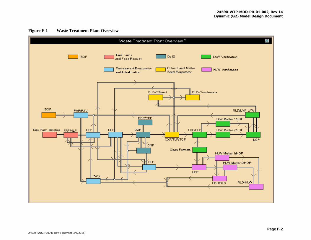
24590-WTP-MDD-PR-01-002, Rev 14 Dynamic (G2) Model Design Document
Page F-2
24590-PADC-F00041 Rev 8 (Revised 3/5/2018)
Figure F-1 Waste Treatment Plant Overview
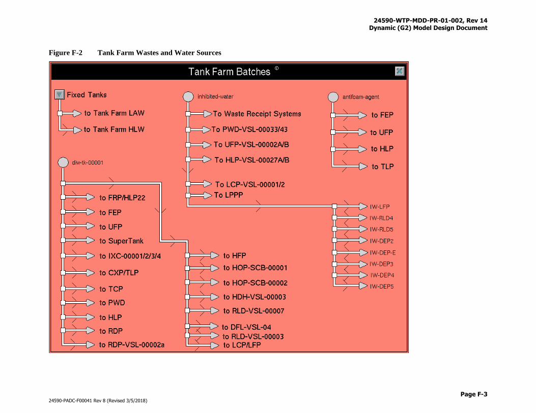
24590-WTP-MDD-PR-01-002, Rev 14 Dynamic (G2) Model Design Document
Page F-3
24590-PADC-F00041 Rev 8 (Revised 3/5/2018)
Figure F-2 Tank Farm Wastes and Water Sources
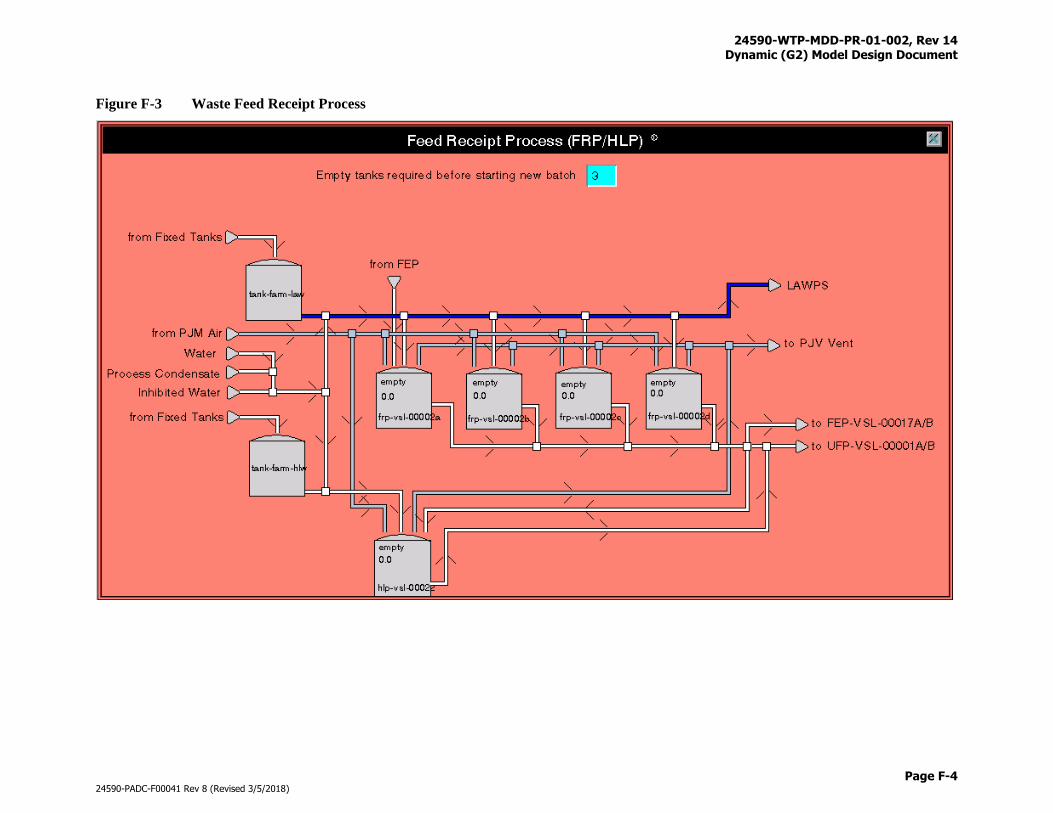
24590-WTP-MDD-PR-01-002, Rev 14 Dynamic (G2) Model Design Document
Page F-4
24590-PADC-F00041 Rev 8 (Revised 3/5/2018)
Figure F-3 Waste Feed Receipt Process
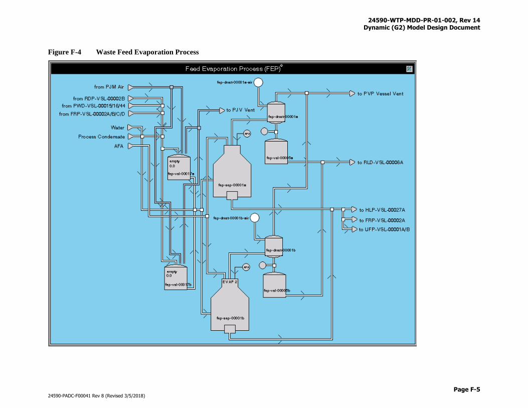
24590-WTP-MDD-PR-01-002, Rev 14 Dynamic (G2) Model Design Document
Page F-5
24590-PADC-F00041 Rev 8 (Revised 3/5/2018)
Figure F-4 Waste Feed Evaporation Process
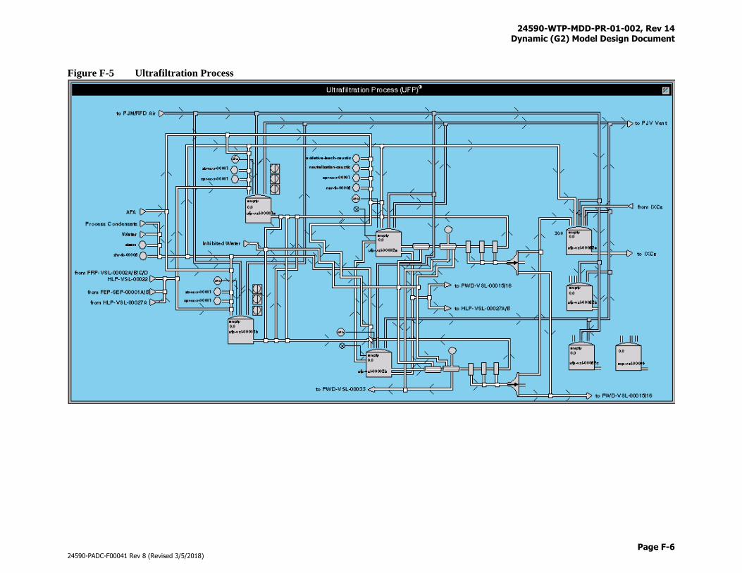
24590-WTP-MDD-PR-01-002, Rev 14 Dynamic (G2) Model Design Document
Page F-6
24590-PADC-F00041 Rev 8 (Revised 3/5/2018)
Figure F-5 Ultrafiltration Process
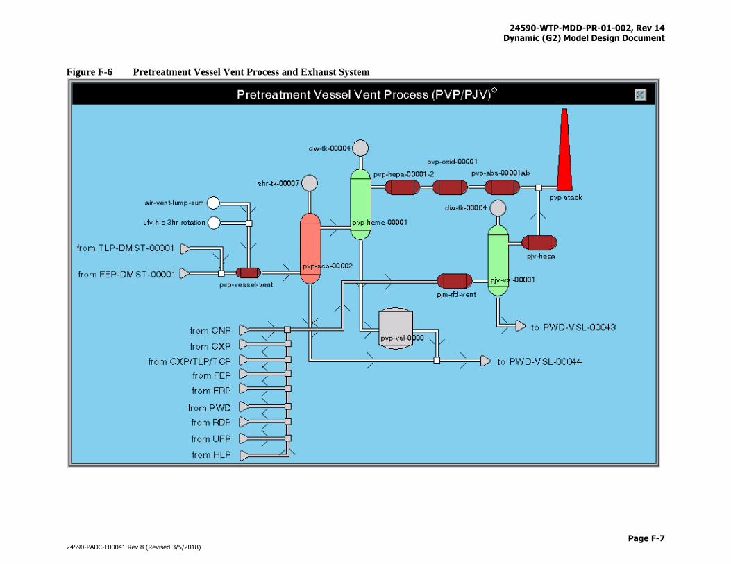
24590-WTP-MDD-PR-01-002, Rev 14 Dynamic (G2) Model Design Document
Page F-7
24590-PADC-F00041 Rev 8 (Revised 3/5/2018)
Figure F-6 Pretreatment Vessel Vent Process and Exhaust System
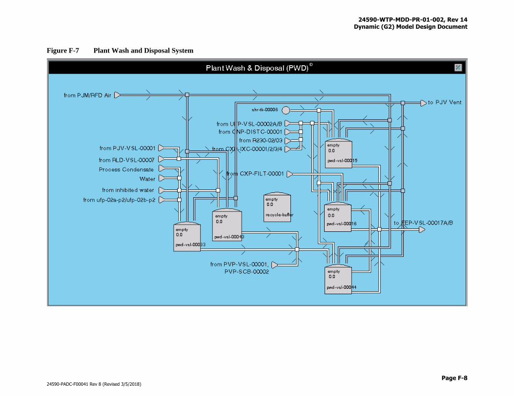
24590-WTP-MDD-PR-01-002, Rev 14 Dynamic (G2) Model Design Document
Page F-8
24590-PADC-F00041 Rev 8 (Revised 3/5/2018)
Figure F-7 Plant Wash and Disposal System
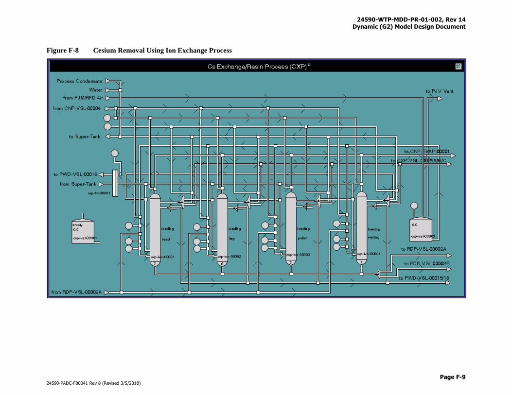
24590-WTP-MDD-PR-01-002, Rev 14 Dynamic (G2) Model Design Document
Page F-9
24590-PADC-F00041 Rev 8 (Revised 3/5/2018)
Figure F-8 Cesium Removal Using Ion Exchange Process
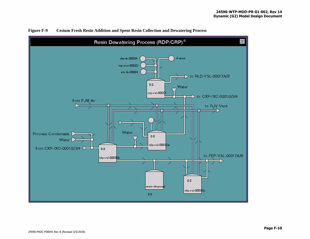
24590-WTP-MDD-PR-01-002, Rev 14 Dynamic (G2) Model Design Document
Page F-10
24590-PADC-F00041 Rev 8 (Revised 3/5/2018)
Figure F-9 Cesium Fresh Resin Addition and Spent Resin Collection and Dewatering Process
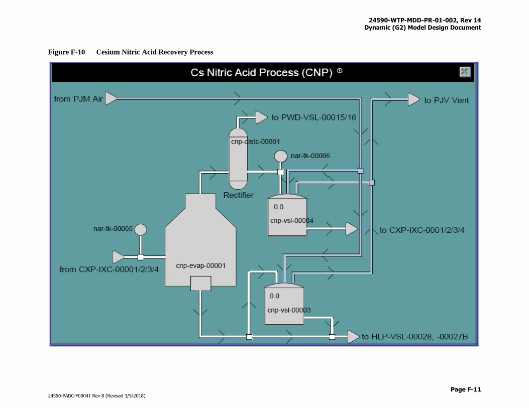
24590-WTP-MDD-PR-01-002, Rev 14 Dynamic (G2) Model Design Document
Page F-11
24590-PADC-F00041 Rev 8 (Revised 3/5/2018)
Figure F-10 Cesium Nitric Acid Recovery Process
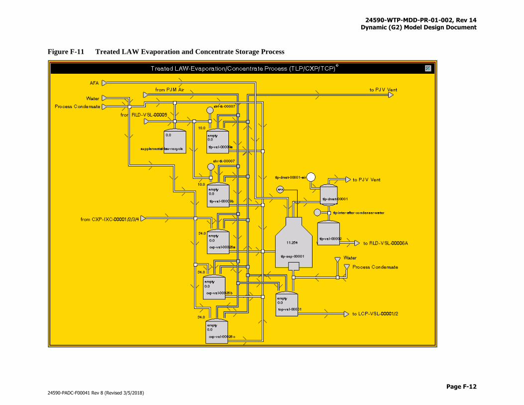
24590-WTP-MDD-PR-01-002, Rev 14 Dynamic (G2) Model Design Document
Page F-12
24590-PADC-F00041 Rev 8 (Revised 3/5/2018)
Figure F-11 Treated LAW Evaporation and Concentrate Storage Process
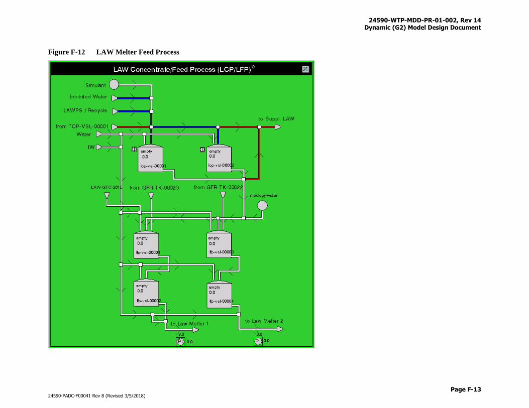
24590-WTP-MDD-PR-01-002, Rev 14 Dynamic (G2) Model Design Document
Page F-13
24590-PADC-F00041 Rev 8 (Revised 3/5/2018)
Figure F-12 LAW Melter Feed Process
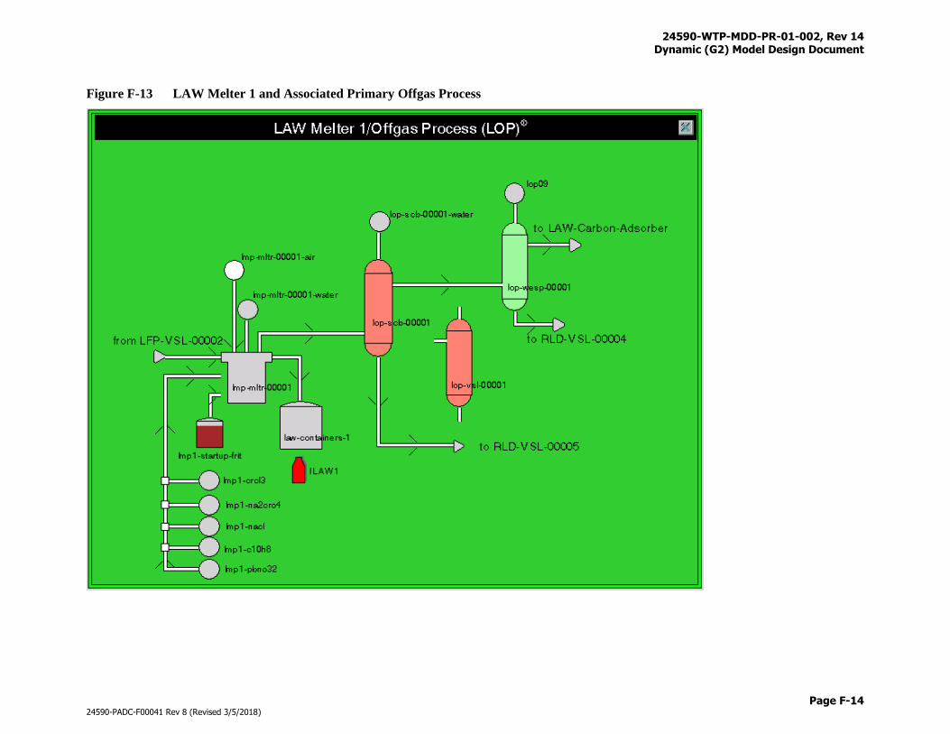
24590-WTP-MDD-PR-01-002, Rev 14 Dynamic (G2) Model Design Document
Page F-14
24590-PADC-F00041 Rev 8 (Revised 3/5/2018)
Figure F-13 LAW Melter 1 and Associated Primary Offgas Process
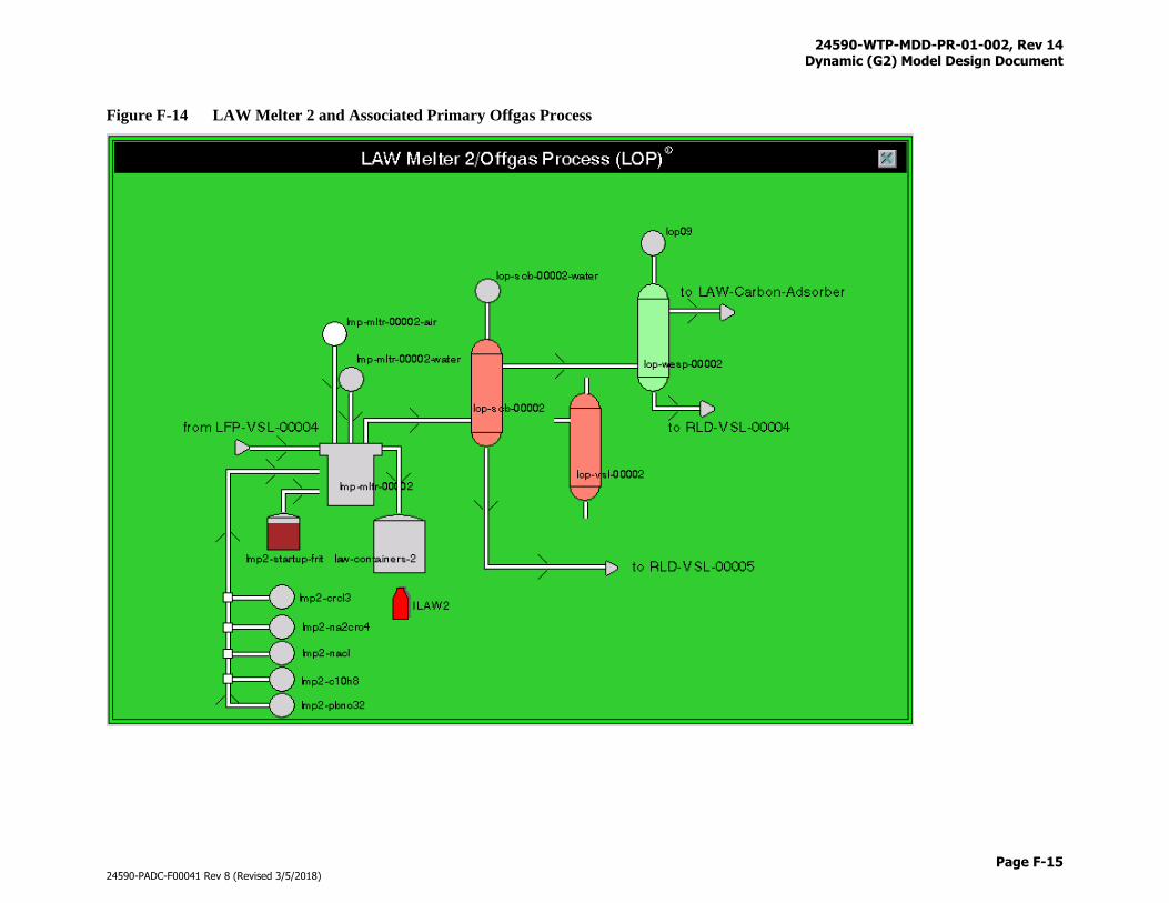
24590-WTP-MDD-PR-01-002, Rev 14 Dynamic (G2) Model Design Document
Page F-15
24590-PADC-F00041 Rev 8 (Revised 3/5/2018)
Figure F-14 LAW Melter 2 and Associated Primary Offgas Process
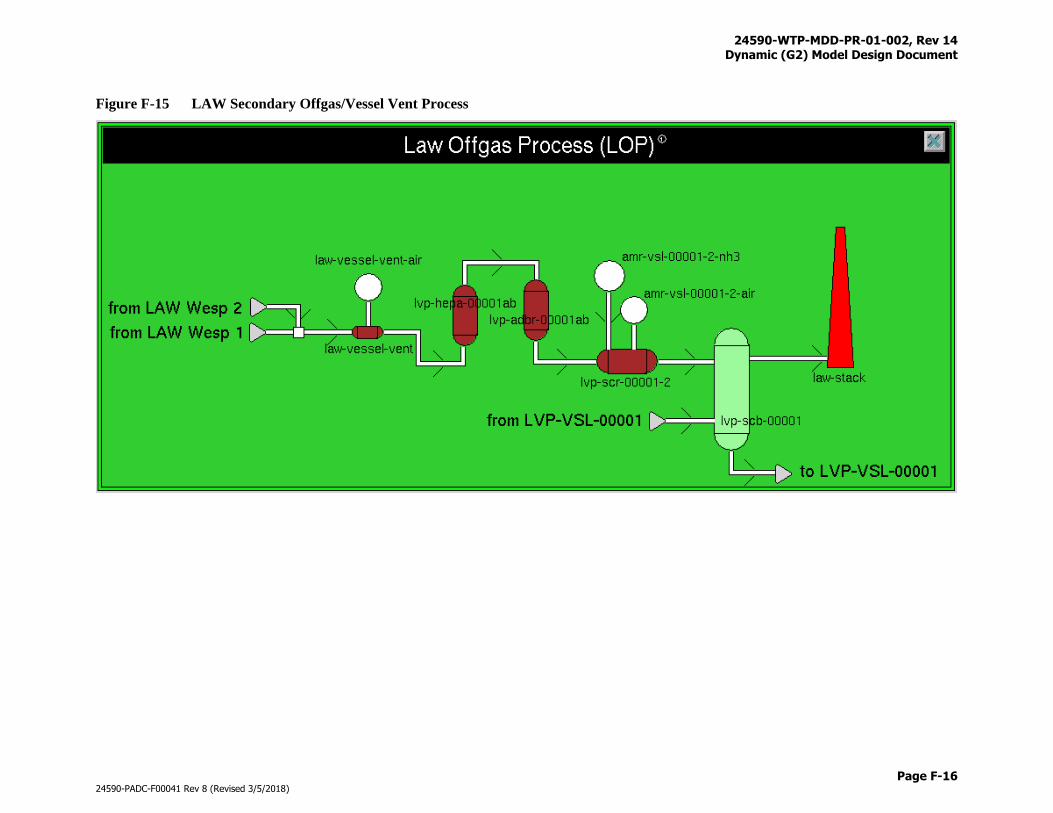
24590-WTP-MDD-PR-01-002, Rev 14 Dynamic (G2) Model Design Document
Page F-16
24590-PADC-F00041 Rev 8 (Revised 3/5/2018)
Figure F-15 LAW Secondary Offgas/Vessel Vent Process
24590-WTP-MDD-PR-01-002, Rev 14 Dynamic (G2) Model Design Document
Page F-17
24590-PADC-F00041 Rev 8 (Revised 3/5/2018)
Figure F-16 LAW Radioactive Liquid Waste Disposal
LVP-TK-00001, RLD-VSL-00003, RLD-VSL-00004, and RLD-VSL-00005 have been moved to the DFLAW workspace (see Figure F-28)
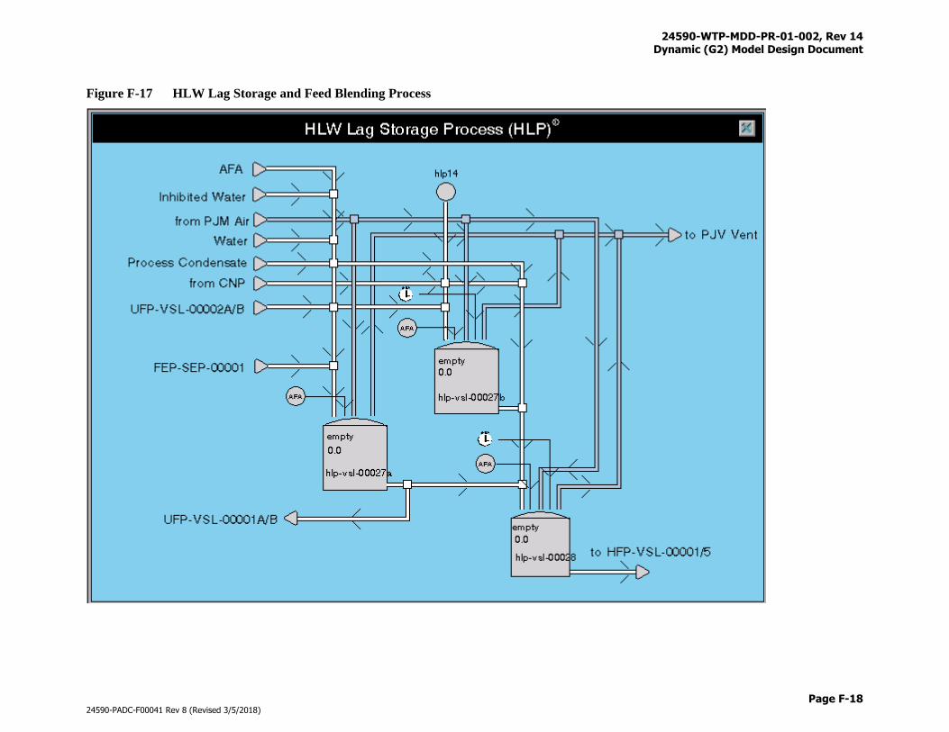
24590-WTP-MDD-PR-01-002, Rev 14 Dynamic (G2) Model Design Document
Page F-18
24590-PADC-F00041 Rev 8 (Revised 3/5/2018)
Figure F-17 HLW Lag Storage and Feed Blending Process
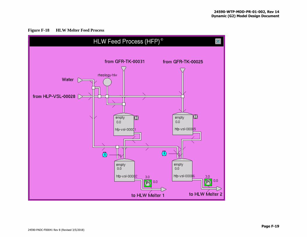
24590-WTP-MDD-PR-01-002, Rev 14 Dynamic (G2) Model Design Document
Page F-19
24590-PADC-F00041 Rev 8 (Revised 3/5/2018)
Figure F-18 HLW Melter Feed Process
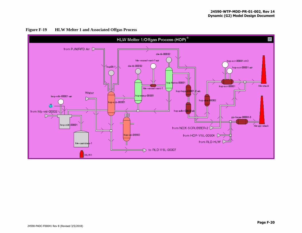
24590-WTP-MDD-PR-01-002, Rev 14 Dynamic (G2) Model Design Document
Page F-20
24590-PADC-F00041 Rev 8 (Revised 3/5/2018)
Figure F-19 HLW Melter 1 and Associated Offgas Process
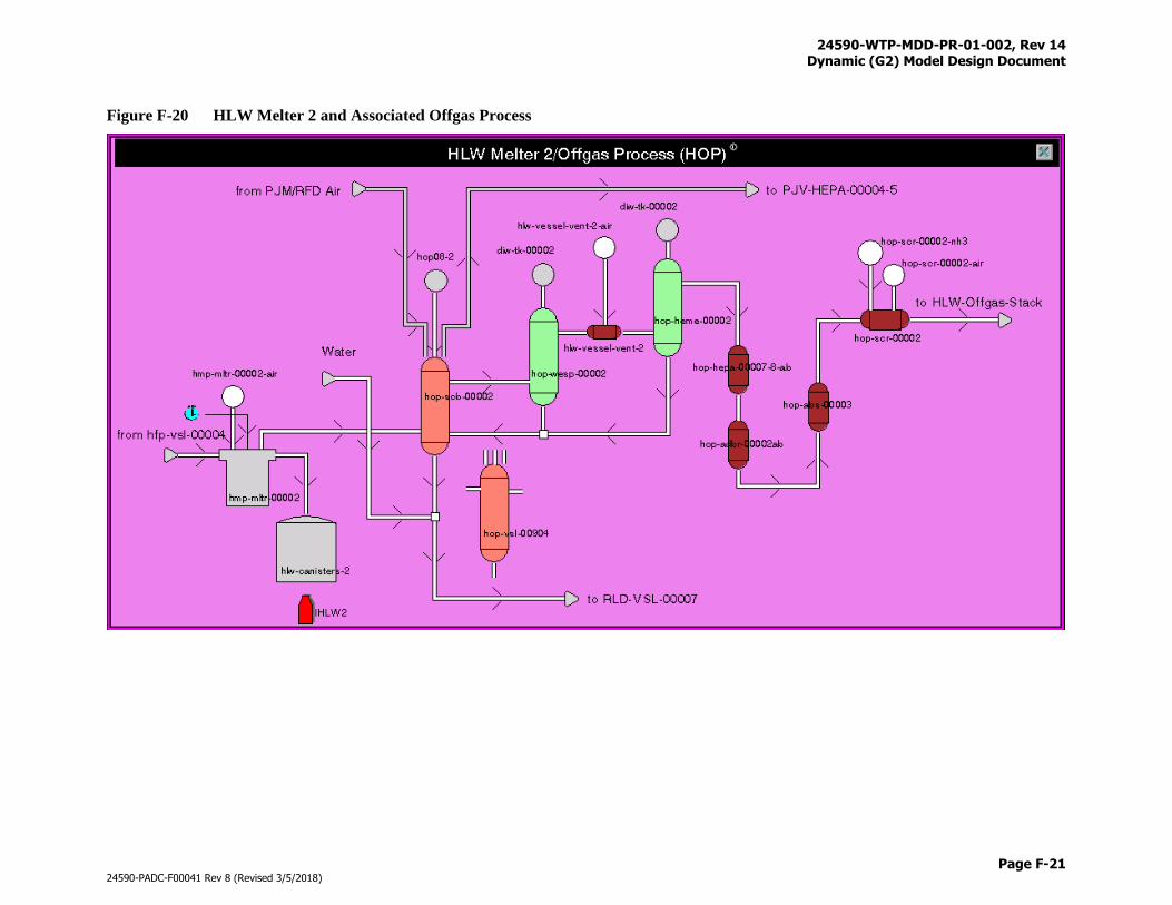
24590-WTP-MDD-PR-01-002, Rev 14 Dynamic (G2) Model Design Document
Page F-21
24590-PADC-F00041 Rev 8 (Revised 3/5/2018)
Figure F-20 HLW Melter 2 and Associated Offgas Process
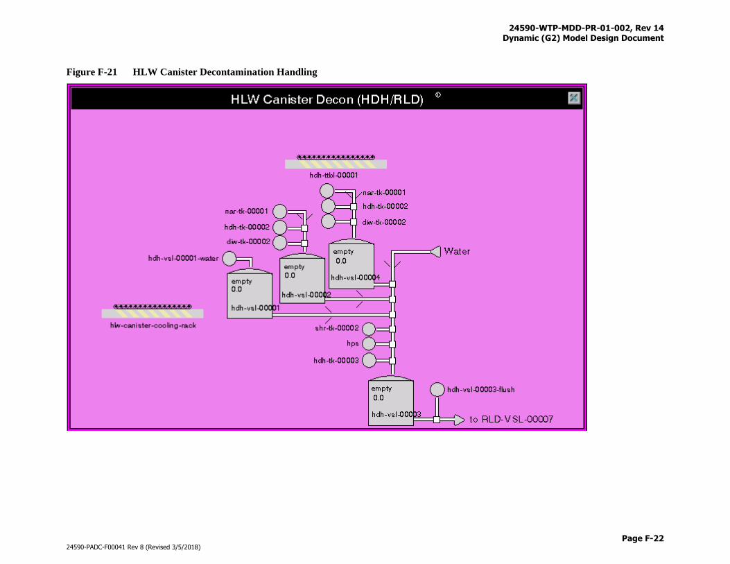
24590-WTP-MDD-PR-01-002, Rev 14 Dynamic (G2) Model Design Document
Page F-22
24590-PADC-F00041 Rev 8 (Revised 3/5/2018)
Figure F-21 HLW Canister Decontamination Handling
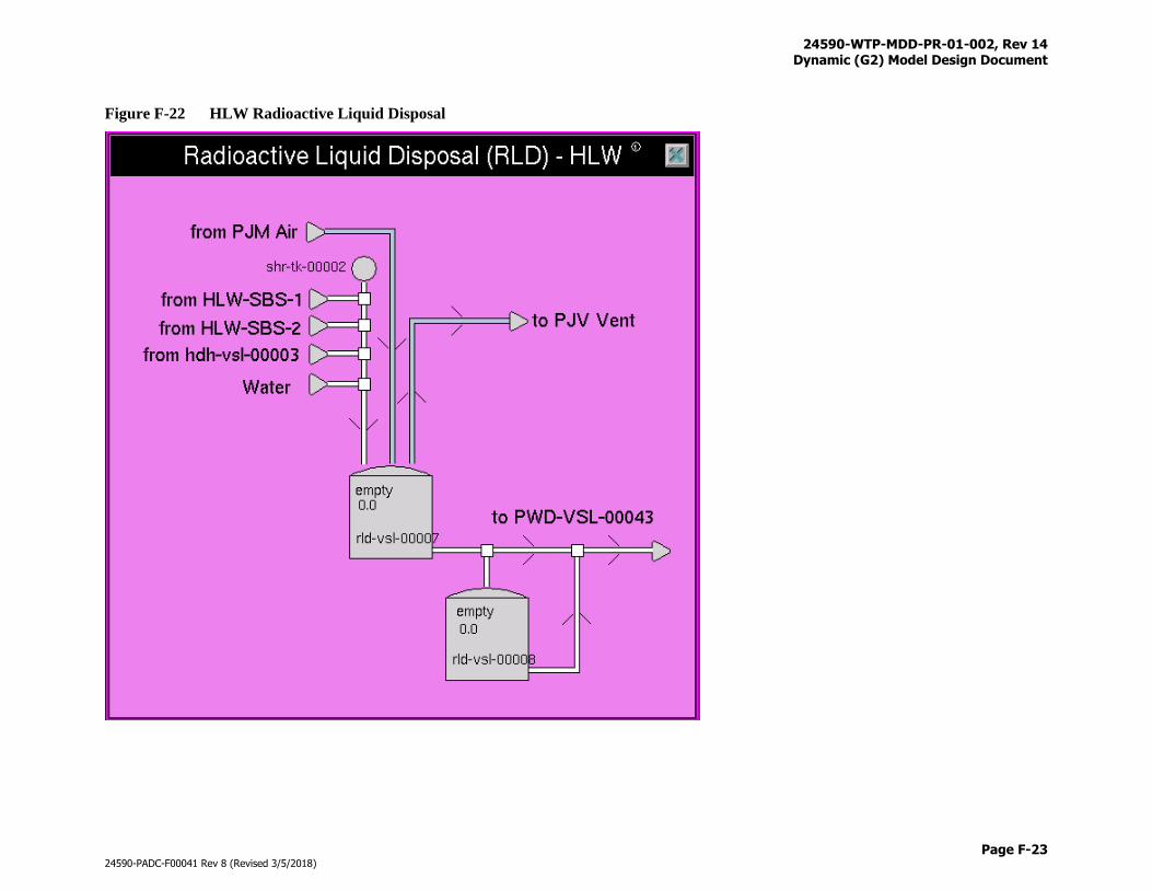
24590-WTP-MDD-PR-01-002, Rev 14 Dynamic (G2) Model Design Document
Page F-23
24590-PADC-F00041 Rev 8 (Revised 3/5/2018)
Figure F-22 HLW Radioactive Liquid Disposal
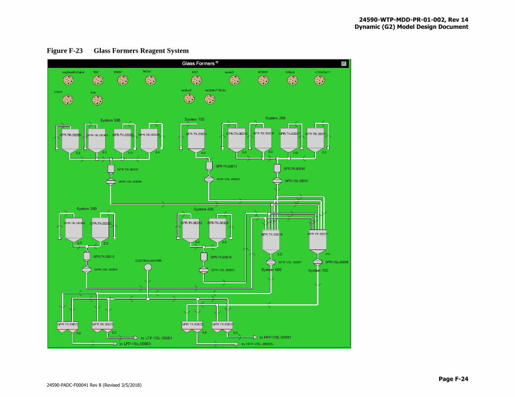
24590-WTP-MDD-PR-01-002, Rev 14 Dynamic (G2) Model Design Document
Page F-24
24590-PADC-F00041 Rev 8 (Revised 3/5/2018)
Figure F-23 Glass Formers Reagent System
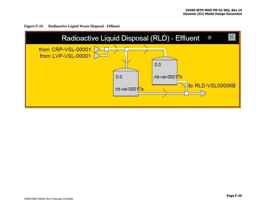
24590-WTP-MDD-PR-01-002, Rev 14 Dynamic (G2) Model Design Document
Page F-25
24590-PADC-F00041 Rev 8 (Revised 3/5/2018)
Figure F-24 Radioactive Liquid Waste Disposal - Effluent
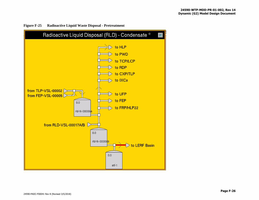
24590-WTP-MDD-PR-01-002, Rev 14 Dynamic (G2) Model Design Document
Page F-26
24590-PADC-F00041 Rev 8 (Revised 3/5/2018)
Figure F-25 Radioactive Liquid Waste Disposal - Pretreatment
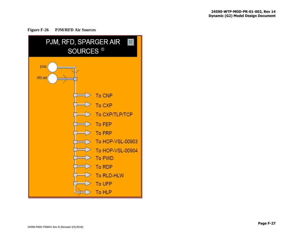
24590-WTP-MDD-PR-01-002, Rev 14 Dynamic (G2) Model Design Document
Page F-27
24590-PADC-F00041 Rev 8 (Revised 3/5/2018)
Figure F-26 PJM/RFD Air Sources
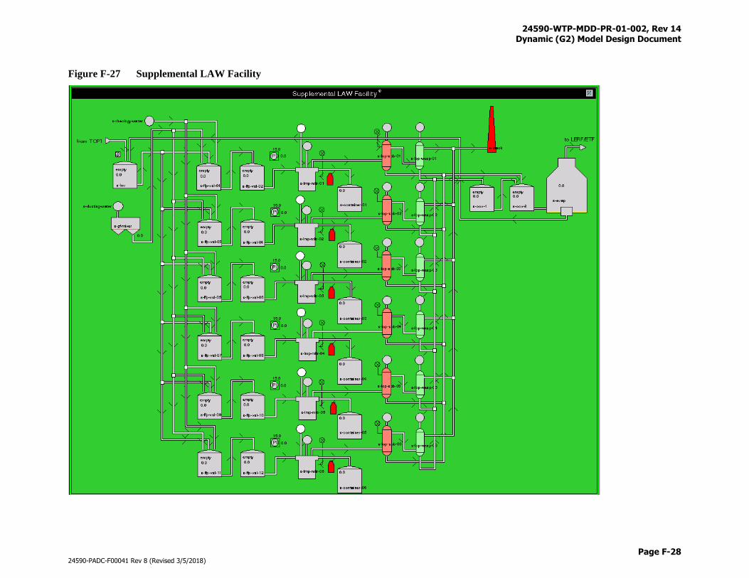
24590-WTP-MDD-PR-01-002, Rev 14 Dynamic (G2) Model Design Document
Page F-28
24590-PADC-F00041 Rev 8 (Revised 3/5/2018)
Figure F-27 Supplemental LAW Facility
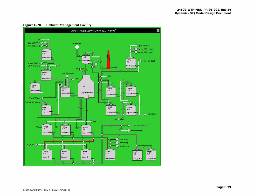
24590-WTP-MDD-PR-01-002, Rev 14 Dynamic (G2) Model Design Document
Page F-29
24590-PADC-F00041 Rev 8 (Revised 3/5/2018)
Figure F-28 Effluent Management Facility
24590-WTP-MDD-PR-01-002, Rev 14 Dynamic (G2) Model Design Document
Page G-i
24590-PADC-F00041 Rev 8 (Revised 3/5/2018)
Appendix G
Dynamic Air Utilization Modeling
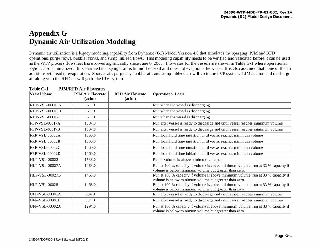
24590-WTP-MDD-PR-01-002, Rev 14 Dynamic (G2) Model Design Document
Page G-1
24590-PADC-F00041 Rev 8 (Revised 3/5/2018)
Appendix G
Dynamic Air Utilization Modeling
Dynamic air utilization is a legacy modeling capability from Dynamic (G2) Model Version 4.0 that simulates the sparging, PJM and RFD
operations, purge flows, bubbler flows, and sump inbleed flows. This modeling capability needs to be verified and validated before it can be used
as the WTP process flowsheet has evolved significantly since June 8, 2005. Flowrates for the vessels are shown in Table G-1 where operational
logic is also summarized. It is assumed that sparger air is humidified so that it does not evaporate the waste. It is also assumed that none of the air
additions will lead to evaporation. Sparger air, purge air, bubbler air, and sump inbleed air will go to the PVP system. PJM suction and discharge
air along with the RFD air will go to the PJV system.
Table G-1 PJM/RFD Air Flowrates Vessel Name PJM Air Flowrate
(acfm)
RFD Air Flowrate
(acfm)
Operational Logic
RDP-VSL-00002A 570.0 Run when the vessel is discharging
RDP-VSL-00002B 570.0 Run when the vessel is discharging
RDP-VSL-00002C 570.0 Run when the vessel is discharging
FEP-VSL-00017A 1007.0 Run after vessel is ready to discharge and until vessel reaches minimum volume
FEP-VSL-00017B 1007.0 Run after vessel is ready to discharge and until vessel reaches minimum volume
FRP-VSL-00002A 1660.0 Run from hold time initiation until vessel reaches minimum volume
FRP-VSL-00002B 1660.0 Run from hold time initiation until vessel reaches minimum volume
FRP-VSL-00002C 1660.0 Run from hold time initiation until vessel reaches minimum volume
FRP-VSL-00002D 1660.0 Run from hold time initiation until vessel reaches minimum volume
HLP-VSL-00022 1536.0 Run if volume is above minimum volume
HLP-VSL-00027A 1463.0 Run at 100 % capacity if volume is above minimum volume, run at 33 % capacity if
volume is below minimum volume but greater than zero.
HLP-VSL-00027B 1463.0 Run at 100 % capacity if volume is above minimum volume, run at 33 % capacity if
volume is below minimum volume but greater than zero.
HLP-VSL-00028 1463.0 Run at 100 % capacity if volume is above minimum volume, run at 33 % capacity if
volume is below minimum volume but greater than zero.
UFP-VSL-00001A 884.0 Run after vessel is ready to discharge and until vessel reaches minimum volume
UFP-VSL-00001B 884.0 Run after vessel is ready to discharge and until vessel reaches minimum volume
UFP-VSL-00002A 1294.0 Run at 100 % capacity if volume is above minimum volume, run at 33 % capacity if
volume is below minimum volume but greater than zero.
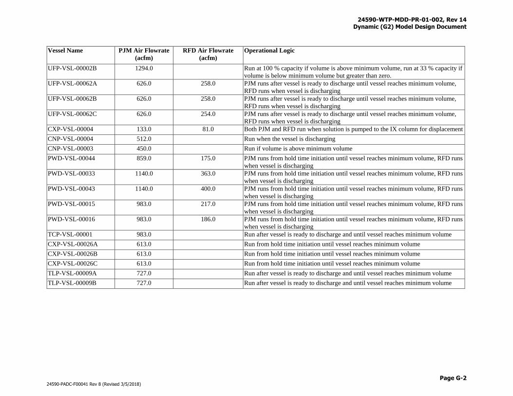
24590-WTP-MDD-PR-01-002, Rev 14 Dynamic (G2) Model Design Document
Page G-2
24590-PADC-F00041 Rev 8 (Revised 3/5/2018)
Vessel Name PJM Air Flowrate
(acfm)
RFD Air Flowrate
(acfm)
Operational Logic
UFP-VSL-00002B 1294.0 Run at 100 % capacity if volume is above minimum volume, run at 33 % capacity if
volume is below minimum volume but greater than zero.
UFP-VSL-00062A 626.0 258.0 PJM runs after vessel is ready to discharge until vessel reaches minimum volume,
RFD runs when vessel is discharging
UFP-VSL-00062B 626.0 258.0 PJM runs after vessel is ready to discharge until vessel reaches minimum volume,
RFD runs when vessel is discharging
UFP-VSL-00062C 626.0 254.0 PJM runs after vessel is ready to discharge until vessel reaches minimum volume,
RFD runs when vessel is discharging
CXP-VSL-00004 133.0 81.0 Both PJM and RFD run when solution is pumped to the IX column for displacement
CNP-VSL-00004 512.0 Run when the vessel is discharging
CNP-VSL-00003 450.0 Run if volume is above minimum volume
PWD-VSL-00044 859.0 175.0 PJM runs from hold time initiation until vessel reaches minimum volume, RFD runs
when vessel is discharging
PWD-VSL-00033 1140.0 363.0 PJM runs from hold time initiation until vessel reaches minimum volume, RFD runs
when vessel is discharging
PWD-VSL-00043 1140.0 400.0 PJM runs from hold time initiation until vessel reaches minimum volume, RFD runs
when vessel is discharging
PWD-VSL-00015 983.0 217.0 PJM runs from hold time initiation until vessel reaches minimum volume, RFD runs
when vessel is discharging
PWD-VSL-00016 983.0 186.0 PJM runs from hold time initiation until vessel reaches minimum volume, RFD runs
when vessel is discharging
TCP-VSL-00001 983.0 Run after vessel is ready to discharge and until vessel reaches minimum volume
CXP-VSL-00026A 613.0 Run from hold time initiation until vessel reaches minimum volume
CXP-VSL-00026B 613.0 Run from hold time initiation until vessel reaches minimum volume
CXP-VSL-00026C 613.0 Run from hold time initiation until vessel reaches minimum volume
TLP-VSL-00009A 727.0 Run after vessel is ready to discharge and until vessel reaches minimum volume
TLP-VSL-00009B 727.0 Run after vessel is ready to discharge and until vessel reaches minimum volume
24590-WTP-MDD-PR-01-002, Rev 14 Dynamic (G2) Model Design Document
Page H-i
24590-PADC-F00041 Rev 8 (Revised 3/5/2018)
Appendix H
Transfer, Sampling, and Time Triggered Line Flushes
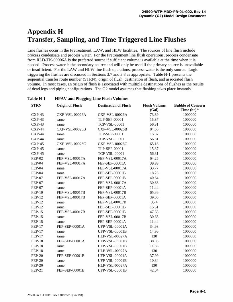
24590-WTP-MDD-PR-01-002, Rev 14 Dynamic (G2) Model Design Document
Page H-1
24590-PADC-F00041 Rev 8 (Revised 3/5/2018)
Appendix H
Transfer, Sampling, and Time Triggered Line Flushes
Line flushes occur in the Pretreatment, LAW, and HLW facilities. The sources of line flush include
process condensate and process water. For the Pretreatment line flush operations, process condensate
from RLD-TK-00006A is the preferred source if sufficient volume is available at the time when it is
needed. Process water is the secondary source and will only be used if the primary source is unavailable
or insufficient. For the LAW and HLW line flush operations, process water is the only source. Logic
triggering the flushes are discussed in Sections 3.7 and 3.8 as appropriate. Table H-1 presents the
sequential transfer route number (STRN), origin of flush, destination of flush, and associated flush
volume. In most cases, an origin of flush is associated with multiple destinations of flushes as the results
of dead legs and piping configurations. The G2 model assumes that flushing takes place instantly.
Table H-1 HPAV and Plugging Line Flush Volumes
STRN Origin of Flush Destination of Flush Flush Volume
(Gal)
Bubble of Concern
Time (hr) a
CXP-43 CXP-VSL-00026A CXP-VSL-00026A 73.89 1000000
CXP-43 same TLP-SEP-00001 15.37 1000000
CXP-43 same TCP-VSL-00001 56.31 1000000
CXP-44 CXP-VSL-00026B CXP-VSL-00026B 84.66 1000000
CXP-44 same TLP-SEP-00001 15.37 1000000
CXP-44 same TCP-VSL-00001 56.31 1000000
CXP-45 CXP-VSL-00026C CXP-VSL-00026C 65.18 1000000
CXP-45 same TLP-SEP-00001 15.37 1000000
CXP-45 same TCP-VSL-00001 56.31 1000000
FEP-02 FEP-VSL-00017A FEP-VSL-00017A 64.25 1000000
FEP-04 FEP-VSL-00017A FEP-SEP-00001A 39.99 1000000
FEP-04 same FEP-VSL-00017A 33.77 1000000
FEP-04 same FEP-SEP-00001B 18.23 1000000
FEP-07 FEP-VSL-00017A FEP-SEP-00001B 40.64 1000000
FEP-07 same FEP-VSL-00017A 30.63 1000000
FEP-07 same FEP-SEP-00001A 11.44 1000000
FEP-10 FEP-VSL-00017B FEP-VSL-00017B 65.36 1000000
FEP-12 FEP-VSL-00017B FEP-SEP-00001A 39.06 1000000
FEP-12 same FEP-VSL-00017B 35.4 1000000
FEP-12 same FEP-SEP-00001B 15.51 1000000
FEP-15 FEP-VSL-00017B FEP-SEP-00001B 47.68 1000000
FEP-15 same FEP-VSL-00017B 30.63 1000000
FEP-15 same FEP-SEP-00001A 11.44 1000000
FEP-17 FEP-SEP-00001A UFP-VSL-00001A 34.93 1000000
FEP-17 same UFP-VSL-00001B 14.96 1000000
FEP-17 same HLP-VSL-00027A 130 1000000
FEP-18 FEP-SEP-00001A UFP-VSL-00001B 38.85 1000000
FEP-18 same UFP-VSL-00001B 11.83 1000000
FEP-18 same HLP-VSL-00027A 130 1000000
FEP-20 FEP-SEP-00001B UFP-VSL-00001A 37.99 1000000
FEP-20 same UFP-VSL-00001B 10.84 1000000
FEP-20 same HLP-VSL-00027A 130 1000000
FEP-21 FEP-SEP-00001B UFP-VSL-00001B 42.04 1000000
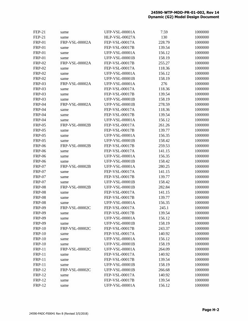
24590-WTP-MDD-PR-01-002, Rev 14 Dynamic (G2) Model Design Document
Page H-2
24590-PADC-F00041 Rev 8 (Revised 3/5/2018)
FEP-21 same UFP-VSL-00001A 7.59 1000000
FEP-21 same HLP-VSL-00027A 130 1000000
FRP-01 FRP-VSL-00002A FEP-VSL-00017A 228.79 1000000
FRP-01 same FEP-VSL-00017B 139.54 1000000
FRP-01 same UFP-VSL-00001A 156.12 1000000
FRP-01 same UFP-VSL-00001B 158.19 1000000
FRP-02 FRP-VSL-00002A FEP-VSL-00017B 255.27 1000000
FRP-02 same FEP-VSL-00017A 118.36 1000000
FRP-02 same UFP-VSL-00001A 156.12 1000000
FRP-02 same UFP-VSL-00001B 158.19 1000000
FRP-03 FRP-VSL-00002A UFP-VSL-00001A 276 1000000
FRP-03 same FEP-VSL-00017A 118.36 1000000
FRP-03 same FEP-VSL-00017B 139.54 1000000
FRP-03 same UFP-VSL-00001B 158.19 1000000
FRP-04 FRP-VSL-00002A UFP-VSL-00001B 278.59 1000000
FRP-04 same FEP-VSL-00017A 118.36 1000000
FRP-04 same FEP-VSL-00017B 139.54 1000000
FRP-04 same UFP-VSL-00001A 156.12 1000000
FRP-05 FRP-VSL-00002B FEP-VSL-00017A 261.26 1000000
FRP-05 same FEP-VSL-00017B 139.77 1000000
FRP-05 same UFP-VSL-00001A 156.35 1000000
FRP-05 same UFP-VSL-00001B 158.42 1000000
FRP-06 FRP-VSL-00002B FEP-VSL-00017B 259.53 1000000
FRP-06 same FEP-VSL-00017A 141.15 1000000
FRP-06 same UFP-VSL-00001A 156.35 1000000
FRP-06 same UFP-VSL-00001B 158.42 1000000
FRP-07 FRP-VSL-00002B UFP-VSL-00001A 280.25 1000000
FRP-07 same FEP-VSL-00017A 141.15 1000000
FRP-07 same FEP-VSL-00017B 139.77 1000000
FRP-07 same UFP-VSL-00001B 158.42 1000000
FRP-08 FRP-VSL-00002B UFP-VSL-00001B 282.84 1000000
FRP-08 same FEP-VSL-00017A 141.15 1000000
FRP-08 same FEP-VSL-00017B 139.77 1000000
FRP-08 same UFP-VSL-00001A 156.35 1000000
FRP-09 FRP-VSL-00002C FEP-VSL-00017A 245.1 1000000
FRP-09 same FEP-VSL-00017B 139.54 1000000
FRP-09 same UFP-VSL-00001A 156.12 1000000
FRP-09 same UFP-VSL-00001B 158.19 1000000
FRP-10 FRP-VSL-00002C FEP-VSL-00017B 243.37 1000000
FRP-10 same FEP-VSL-00017A 140.92 1000000
FRP-10 same UFP-VSL-00001A 156.12 1000000
FRP-10 same UFP-VSL-00001B 158.19 1000000
FRP-11 FRP-VSL-00002C UFP-VSL-00001A 264.09 1000000
FRP-11 same FEP-VSL-00017A 140.92 1000000
FRP-11 same FEP-VSL-00017B 139.54 1000000
FRP-11 same UFP-VSL-00001B 158.19 1000000
FRP-12 FRP-VSL-00002C UFP-VSL-00001B 266.68 1000000
FRP-12 same FEP-VSL-00017A 140.92 1000000
FRP-12 same FEP-VSL-00017B 139.54 1000000
FRP-12 same UFP-VSL-00001A 156.12 1000000
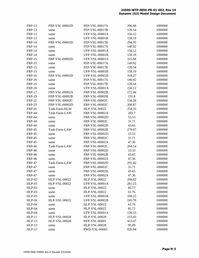
24590-WTP-MDD-PR-01-002, Rev 14 Dynamic (G2) Model Design Document
Page H-3
24590-PADC-F00041 Rev 8 (Revised 3/5/2018)
FRP-13 FRP-VSL-00002D FEP-VSL-00017A 296.68 1000000
FRP-13 same FEP-VSL-00017B 139.54 1000000
FRP-13 same UFP-VSL-00001A 156.12 1000000
FRP-13 same UFP-VSL-00001B 158.19 1000000
FRP-14 FRP-VSL-00002D FEP-VSL-00017B 294.95 1000000
FRP-14 same FEP-VSL-00017A 140.92 1000000
FRP-14 same UFP-VSL-00001A 156.12 1000000
FRP-14 same UFP-VSL-00001B 158.19 1000000
FRP-15 FRP-VSL-00002D UFP-VSL-00001A 315.68 1000000
FRP-15 same FEP-VSL-00017A 140.92 1000000
FRP-15 same FEP-VSL-00017B 139.54 1000000
FRP-15 same UFP-VSL-00001B 158.19 1000000
FRP-16 FRP-VSL-00002D UFP-VSL-00001B 318.27 1000000
FRP-16 same FEP-VSL-00017A 140.92 1000000
FRP-16 same FEP-VSL-00017B 139.54 1000000
FRP-16 same UFP-VSL-00001A 156.12 1000000
FRP-17 FRP-VSL-00002A FRP-VSL-00002B 172.66 1000000
FRP-19 FRP-VSL-00002B FRP-VSL-00002B 155.8 1000000
FRP-21 FRP-VSL-00002C FRP-VSL-00002C 158.28 1000000
FRP-23 FRP-VSL-00002D FRP-VSL-00002C 208.87 1000000
FRP-41 Tank-Farm-HLW HLP-VSL-00022 254.33 1000000
FRP-44 Tank-Farm-LAW FRP-VSL-00002A 283.7 1000000
FRP-44 same FRP-VSL-00002D 53.53 1000000
FRP-44 same FRP-VSL-00002C 31.71 1000000
FRP-44 same FRP-VSL-00002B 43.65 1000000
FRP-45 Tank-Farm-LAW FRP-VSL-00002B 279.07 1000000
FRP-45 same FRP-VSL-00002D 53.53 1000000
FRP-45 same FRP-VSL-00002C 31.71 1000000
FRP-45 same FRP-VSL-00002A 47.36 1000000
FRP-46 Tank-Farm-LAW FRP-VSL-00002C 264.14 1000000
FRP-46 same FRP-VSL-00002D 53.53 1000000
FRP-46 same FRP-VSL-00002B 43.65 1000000
FRP-46 same FRP-VSL-00002A 47.36 1000000
FRP-47 Tank-Farm-LAW FRP-VSL-00002D 291.42 1000000
FRP-47 same FRP-VSL-00002C 31.71 1000000
FRP-47 same FRP-VSL-00002B 43.65 1000000
FRP-47 same FRP-VSL-00002A 47.36 1000000
HLP-02 HLP-VSL-00022 HLP-VSL-00022 294.82 1000000
HLP-03 HLP-VSL-00022 UFP-VSL-00001A 261.15 1000000
HLP-03 same HLP-VSL-00022 85.77 1000000
HLP-03 same HLP-VSL-00022 61.76 1000000
HLP-03 same UFP-VSL-00001B 108.25 1000000
HLP-04 HLP-VSL-00022 UFP-VSL-00001B 245.78 1000000
HLP-04 same HLP-VSL-00022 61.76 1000000
HLP-04 same HLP-VSL-00022 85.72 1000000
HLP-04 same UFP-VSL-00001A 120.55 1000000
HLP-11 HLP-VSL-00028 HLP-VSL-00028 153.43 1000000
HLP-13 HLP-VSL-00028 HFP-VSL-00005 413.47 1000000
HLP-13 same HLP-VSL-00028 95.09 1000000
HLP-13 same PWD-VSL-00043 826.94 1000000
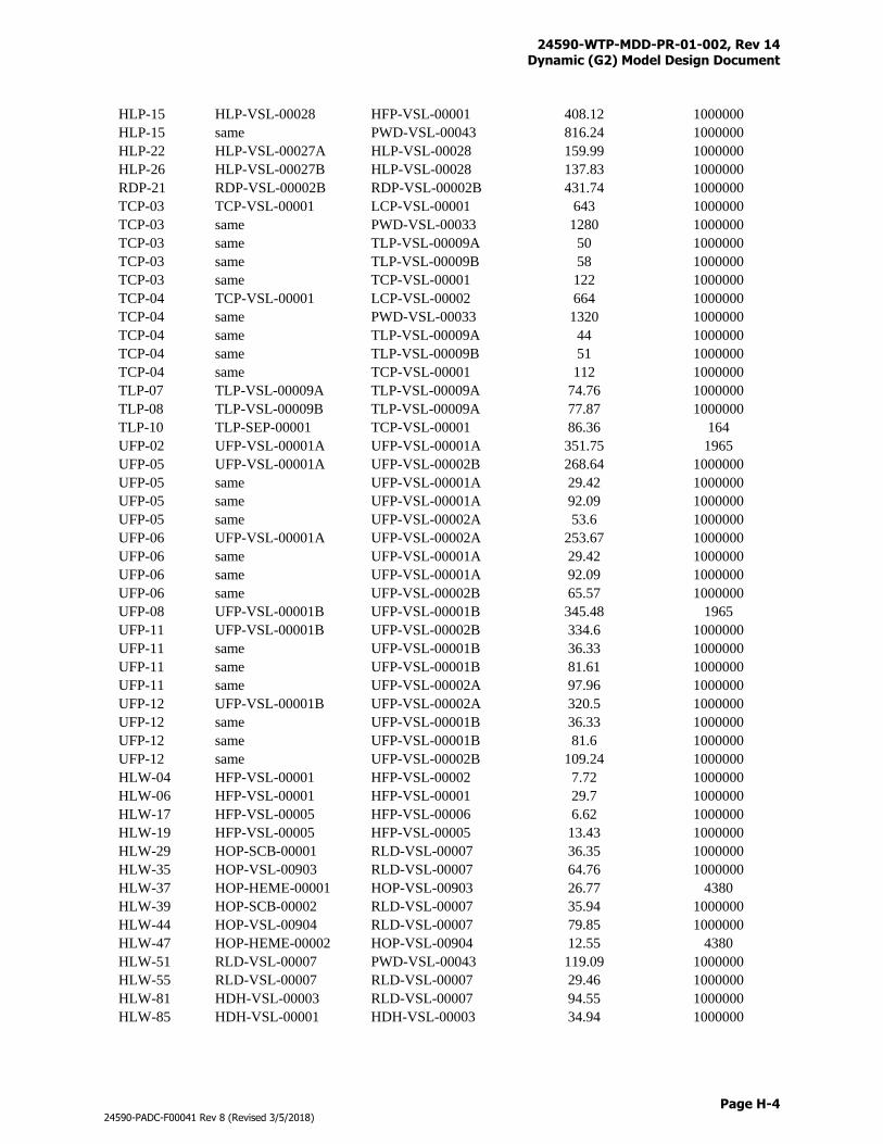
24590-WTP-MDD-PR-01-002, Rev 14 Dynamic (G2) Model Design Document
Page H-4
24590-PADC-F00041 Rev 8 (Revised 3/5/2018)
HLP-15 HLP-VSL-00028 HFP-VSL-00001 408.12 1000000
HLP-15 same PWD-VSL-00043 816.24 1000000
HLP-22 HLP-VSL-00027A HLP-VSL-00028 159.99 1000000
HLP-26 HLP-VSL-00027B HLP-VSL-00028 137.83 1000000
RDP-21 RDP-VSL-00002B RDP-VSL-00002B 431.74 1000000
TCP-03 TCP-VSL-00001 LCP-VSL-00001 643 1000000
TCP-03 same PWD-VSL-00033 1280 1000000
TCP-03 same TLP-VSL-00009A 50 1000000
TCP-03 same TLP-VSL-00009B 58 1000000
TCP-03 same TCP-VSL-00001 122 1000000
TCP-04 TCP-VSL-00001 LCP-VSL-00002 664 1000000
TCP-04 same PWD-VSL-00033 1320 1000000
TCP-04 same TLP-VSL-00009A 44 1000000
TCP-04 same TLP-VSL-00009B 51 1000000
TCP-04 same TCP-VSL-00001 112 1000000
TLP-07 TLP-VSL-00009A TLP-VSL-00009A 74.76 1000000
TLP-08 TLP-VSL-00009B TLP-VSL-00009A 77.87 1000000
TLP-10 TLP-SEP-00001 TCP-VSL-00001 86.36 164
UFP-02 UFP-VSL-00001A UFP-VSL-00001A 351.75 1965
UFP-05 UFP-VSL-00001A UFP-VSL-00002B 268.64 1000000
UFP-05 same UFP-VSL-00001A 29.42 1000000
UFP-05 same UFP-VSL-00001A 92.09 1000000
UFP-05 same UFP-VSL-00002A 53.6 1000000
UFP-06 UFP-VSL-00001A UFP-VSL-00002A 253.67 1000000
UFP-06 same UFP-VSL-00001A 29.42 1000000
UFP-06 same UFP-VSL-00001A 92.09 1000000
UFP-06 same UFP-VSL-00002B 65.57 1000000
UFP-08 UFP-VSL-00001B UFP-VSL-00001B 345.48 1965
UFP-11 UFP-VSL-00001B UFP-VSL-00002B 334.6 1000000
UFP-11 same UFP-VSL-00001B 36.33 1000000
UFP-11 same UFP-VSL-00001B 81.61 1000000
UFP-11 same UFP-VSL-00002A 97.96 1000000
UFP-12 UFP-VSL-00001B UFP-VSL-00002A 320.5 1000000
UFP-12 same UFP-VSL-00001B 36.33 1000000
UFP-12 same UFP-VSL-00001B 81.6 1000000
UFP-12 same UFP-VSL-00002B 109.24 1000000
HLW-04 HFP-VSL-00001 HFP-VSL-00002 7.72 1000000
HLW-06 HFP-VSL-00001 HFP-VSL-00001 29.7 1000000
HLW-17 HFP-VSL-00005 HFP-VSL-00006 6.62 1000000
HLW-19 HFP-VSL-00005 HFP-VSL-00005 13.43 1000000
HLW-29 HOP-SCB-00001 RLD-VSL-00007 36.35 1000000
HLW-35 HOP-VSL-00903 RLD-VSL-00007 64.76 1000000
HLW-37 HOP-HEME-00001 HOP-VSL-00903 26.77 4380
HLW-39 HOP-SCB-00002 RLD-VSL-00007 35.94 1000000
HLW-44 HOP-VSL-00904 RLD-VSL-00007 79.85 1000000
HLW-47 HOP-HEME-00002 HOP-VSL-00904 12.55 4380
HLW-51 RLD-VSL-00007 PWD-VSL-00043 119.09 1000000
HLW-55 RLD-VSL-00007 RLD-VSL-00007 29.46 1000000
HLW-81 HDH-VSL-00003 RLD-VSL-00007 94.55 1000000
HLW-85 HDH-VSL-00001 HDH-VSL-00003 34.94 1000000
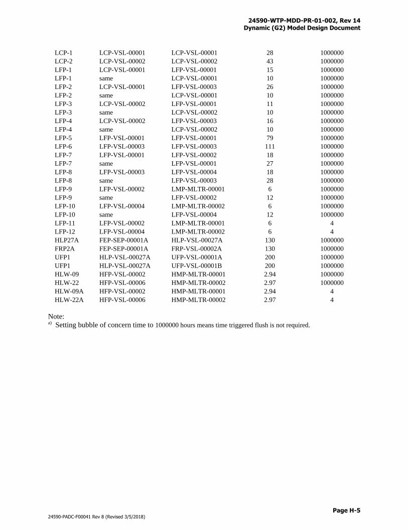
24590-WTP-MDD-PR-01-002, Rev 14 Dynamic (G2) Model Design Document
Page H-5
24590-PADC-F00041 Rev 8 (Revised 3/5/2018)
LCP-1 LCP-VSL-00001 LCP-VSL-00001 28 1000000
LCP-2 LCP-VSL-00002 LCP-VSL-00002 43 1000000
LFP-1 LCP-VSL-00001 LFP-VSL-00001 15 1000000
LFP-1 same LCP-VSL-00001 10 1000000
LFP-2 LCP-VSL-00001 LFP-VSL-00003 26 1000000
LFP-2 same LCP-VSL-00001 10 1000000
LFP-3 LCP-VSL-00002 LFP-VSL-00001 11 1000000
LFP-3 same LCP-VSL-00002 10 1000000
LFP-4 LCP-VSL-00002 LFP-VSL-00003 16 1000000
LFP-4 same LCP-VSL-00002 10 1000000
LFP-5 LFP-VSL-00001 LFP-VSL-00001 79 1000000
LFP-6 LFP-VSL-00003 LFP-VSL-00003 111 1000000
LFP-7 LFP-VSL-00001 LFP-VSL-00002 18 1000000
LFP-7 same LFP-VSL-00001 27 1000000
LFP-8 LFP-VSL-00003 LFP-VSL-00004 18 1000000
LFP-8 same LFP-VSL-00003 28 1000000
LFP-9 LFP-VSL-00002 LMP-MLTR-00001 6 1000000
LFP-9 same LFP-VSL-00002 12 1000000
LFP-10 LFP-VSL-00004 LMP-MLTR-00002 6 1000000
LFP-10 same LFP-VSL-00004 12 1000000
LFP-11 LFP-VSL-00002 LMP-MLTR-00001 6 4
LFP-12 LFP-VSL-00004 LMP-MLTR-00002 6 4
HLP27A FEP-SEP-00001A HLP-VSL-00027A 130 1000000
FRP2A FEP-SEP-00001A FRP-VSL-00002A 130 1000000
UFP1 HLP-VSL-00027A UFP-VSL-00001A 200 1000000
UFP1 HLP-VSL-00027A UFP-VSL-00001B 200 1000000
HLW-09 HFP-VSL-00002 HMP-MLTR-00001 2.94 1000000
HLW-22 HFP-VSL-00006 HMP-MLTR-00002 2.97 1000000
HLW-09A HFP-VSL-00002 HMP-MLTR-00001 2.94 4
HLW-22A HFP-VSL-00006 HMP-MLTR-00002 2.97 4
Note: a) Setting bubble of concern time to 1000000 hours means time triggered flush is not required.

24590-WTP-MDD-PR-01-002, Rev 14 Dynamic (G2) Model Design Document
Page I-i
24590-PADC-F00041 Rev 8 (Revised 3/5/2018)
Appendix I
Feed Vector Charge Balance
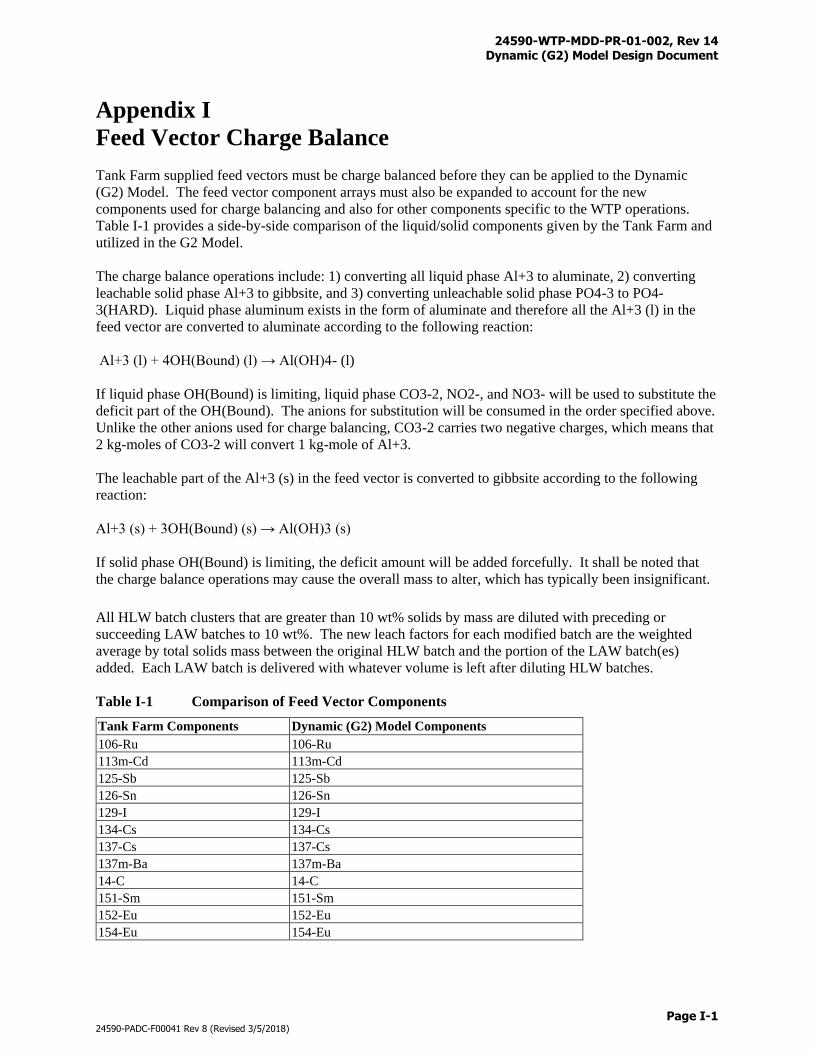
24590-WTP-MDD-PR-01-002, Rev 14 Dynamic (G2) Model Design Document
Page I-1
24590-PADC-F00041 Rev 8 (Revised 3/5/2018)
Appendix I
Feed Vector Charge Balance
Tank Farm supplied feed vectors must be charge balanced before they can be applied to the Dynamic
(G2) Model. The feed vector component arrays must also be expanded to account for the new
components used for charge balancing and also for other components specific to the WTP operations.
Table I-1 provides a side-by-side comparison of the liquid/solid components given by the Tank Farm and
utilized in the G2 Model.
The charge balance operations include: 1) converting all liquid phase Al+3 to aluminate, 2) converting
leachable solid phase Al+3 to gibbsite, and 3) converting unleachable solid phase PO4-3 to PO4-
3(HARD). Liquid phase aluminum exists in the form of aluminate and therefore all the Al+3 (l) in the
feed vector are converted to aluminate according to the following reaction:
Al+3 (l) + 4OH(Bound) (l) → Al(OH)4- (l)
If liquid phase OH(Bound) is limiting, liquid phase CO3-2, NO2-, and NO3- will be used to substitute the
deficit part of the OH(Bound). The anions for substitution will be consumed in the order specified above.
Unlike the other anions used for charge balancing, CO3-2 carries two negative charges, which means that
2 kg-moles of CO3-2 will convert 1 kg-mole of Al+3.
The leachable part of the Al+3 (s) in the feed vector is converted to gibbsite according to the following
reaction:
Al+3 (s) + 3OH(Bound) (s) → Al(OH)3 (s)
If solid phase OH(Bound) is limiting, the deficit amount will be added forcefully. It shall be noted that
the charge balance operations may cause the overall mass to alter, which has typically been insignificant.
All HLW batch clusters that are greater than 10 wt% solids by mass are diluted with preceding or
succeeding LAW batches to 10 wt%. The new leach factors for each modified batch are the weighted
average by total solids mass between the original HLW batch and the portion of the LAW batch(es)
added. Each LAW batch is delivered with whatever volume is left after diluting HLW batches.
Table I-1 Comparison of Feed Vector Components
Tank Farm Components Dynamic (G2) Model Components
106-Ru 106-Ru
113m-Cd 113m-Cd
125-Sb 125-Sb
126-Sn 126-Sn
129-I 129-I
134-Cs 134-Cs
137-Cs 137-Cs
137m-Ba 137m-Ba
14-C 14-C
151-Sm 151-Sm
152-Eu 152-Eu
154-Eu 154-Eu
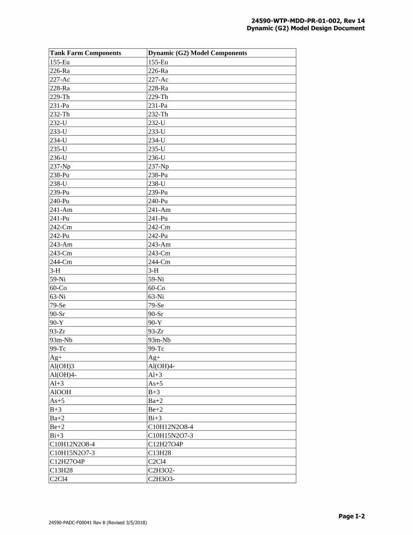
24590-WTP-MDD-PR-01-002, Rev 14 Dynamic (G2) Model Design Document
Page I-2
24590-PADC-F00041 Rev 8 (Revised 3/5/2018)
Tank Farm Components Dynamic (G2) Model Components
155-Eu 155-Eu
226-Ra 226-Ra
227-Ac 227-Ac
228-Ra 228-Ra
229-Th 229-Th
231-Pa 231-Pa
232-Th 232-Th
232-U 232-U
233-U 233-U
234-U 234-U
235-U 235-U
236-U 236-U
237-Np 237-Np
238-Pu 238-Pu
238-U 238-U
239-Pu 239-Pu
240-Pu 240-Pu
241-Am 241-Am
241-Pu 241-Pu
242-Cm 242-Cm
242-Pu 242-Pu
243-Am 243-Am
243-Cm 243-Cm
244-Cm 244-Cm
3-H 3-H
59-Ni 59-Ni
60-Co 60-Co
63-Ni 63-Ni
79-Se 79-Se
90-Sr 90-Sr
90-Y 90-Y
93-Zr 93-Zr
93m-Nb 93m-Nb
99-Tc 99-Tc
Ag+ Ag+
Al(OH)3 Al(OH)4-
Al(OH)4- Al+3
Al+3 As+5
AlOOH B+3
As+5 Ba+2
B+3 Be+2
Ba+2 Bi+3
Be+2 C10H12N2O8-4
Bi+3 C10H15N2O7-3
C10H12N2O8-4 C12H27O4P
C10H15N2O7-3 C13H28
C12H27O4P C2Cl4
C13H28 C2H3O2-
C2Cl4 C2H3O3-
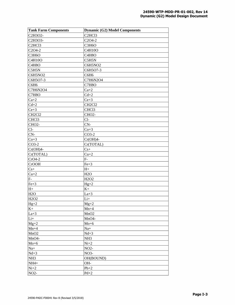
24590-WTP-MDD-PR-01-002, Rev 14 Dynamic (G2) Model Design Document
Page I-3
24590-PADC-F00041 Rev 8 (Revised 3/5/2018)
Tank Farm Components Dynamic (G2) Model Components
C2H3O2- C2HCl3
C2H3O3- C2O4-2
C2HCl3 C3H6O
C2O4-2 C4H10O
C3H6O C4H8O
C4H10O C5H5N
C4H8O C6H5NO2
C5H5N C6H5O7-3
C6H5NO2 C6H6
C6H5O7-3 C7H6N2O4
C6H6 C7H8O
C7H6N2O4 Ca+2
C7H8O Cd+2
Ca+2 Ce+3
Cd+2 CH2Cl2
Ce+3 CHCl3
CH2Cl2 CHO2-
CHCl3 Cl-
CHO2- CN-
Cl- Co+3
CN- CO3-2
Co+3 Cr(OH)4-
CO3-2 Cr(TOTAL)
Cr(OH)4- Cs+
Cr(TOTAL) Cu+2
CrO4-2 F-
CrOOH Fe+3
Cs+ H+
Cu+2 H2O
F- H2O2
Fe+3 Hg+2
H+ K+
H2O La+3
H2O2 Li+
Hg+2 Mg+2
K+ Mn+4
La+3 MnO2
Li+ MnO4-
Mg+2 Mo+6
Mn+4 Na+
MnO2 Nd+3
MnO4- NH3
Mo+6 Ni+2
Na+ NO2-
Nd+3 NO3-
NH3 OH(BOUND)
NH4+ OH-
Ni+2 Pb+2
NO2- Pd+2
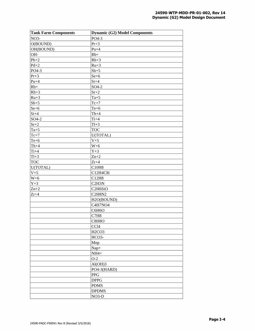
24590-WTP-MDD-PR-01-002, Rev 14 Dynamic (G2) Model Design Document
Page I-4
24590-PADC-F00041 Rev 8 (Revised 3/5/2018)
Tank Farm Components Dynamic (G2) Model Components
NO3- PO4-3
O(BOUND) Pr+3
OH(BOUND) Pu+4
OH- Rb+
Pb+2 Rh+3
Pd+2 Ru+3
PO4-3 Sb+5
Pr+3 Se+6
Pu+4 Si+4
Rb+ SO4-2
Rh+3 Sr+2
Ru+3 Ta+5
Sb+5 Tc+7
Se+6 Te+6
Si+4 Th+4
SO4-2 Ti+4
Sr+2 Tl+3
Ta+5 TOC
Tc+7 U(TOTAL)
Te+6 V+5
Th+4 W+6
Ti+4 Y+3
Tl+3 Zn+2
TOC Zr+4
U(TOTAL) C10H8
V+5 C12H4Cl6
W+6 C12H8
Y+3 C2H3N
Zn+2 C2H6SiO
Zr+4 C2H8N2
H2O(BOUND)
C4H7NO4
C6H6O
C7H8
C8H8O
CCl4
H2CO3
HCO3-
Mnp
Nap+
NH4+
O-2
Al(OH)3
PO4-3(HARD)
PPG
DPPG
PDMS
DPDMS
NO3-D
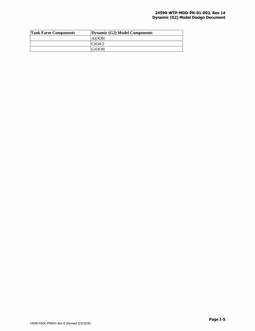
24590-WTP-MDD-PR-01-002, Rev 14 Dynamic (G2) Model Design Document
Page I-5
24590-PADC-F00041 Rev 8 (Revised 3/5/2018)
Tank Farm Components Dynamic (G2) Model Components
AlOOH
CrO4-2
CrOOH
24590-WTP-MDD-PR-01-002, Rev 14 Dynamic (G2) Model Design Document
Page J-i
24590-PADC-F00041 Rev 8 (Revised 3/5/2018)
Appendix J
Mass Balance Flowsheet Diagrams and Volume Throughput
24590-WTP-MDD-PR-01-002, Rev 14 Dynamic (G2) Model Design Document
Page J-1
24590-PADC-F00041 Rev 8 (Revised 3/5/2018)
Appendix J
Mass Balance Flowsheet Diagrams and Volume Throughput
Simplified mass balance flowsheet diagrams are generated with the G2MBC routine (Figure 43) to
support flowsheet developments and model validations. These diagrams present the cumulative masses
over the mission for process streams on the systems level. The diagrams are presented in six Excel
spreadsheets, namely: PT-1, PT-2, LAW, HLW, SLAW, and EMF as shown in Figures J-1 through J-6.
Types of mass balance and flowsheet diagrams include:
Aluminum
Oxalate
Naphthalene
Chloride
Chromium
Cesium 137
Total mass
Total volume
Floride
Iron
Water
Mercury
Iodine 129
Sodium
Phosphate
Radioactivity
Sulfate
Strontium 90
Technetium 99
Mass balance of each system is calculated based on the equation below
∑ 𝐿𝑀𝑠𝑡𝑜[𝑖]
𝑙
= ∑ 𝐶𝑀𝑖𝑛[𝑖]
𝑚
− ∑ 𝐶𝑀𝑜𝑢𝑡[𝑖]
𝑛
Where:
LMsto[i] = Leftover mass of component i in storage in the system at the end of mission (kg)
CMin[i] = Cumulative mass of component i into the system over the mission (kg)
CMout[i] = Cumulative mass of component i out of the system over the mission (kg)
l = Number of process equipment in the system (unitless)
m = Number of process streams into the system (unitless)
n = Number of Process streams out of the system (unitless)
CMin[i] and CMout[i] are extracted from the G2 totalizer data and are posted numerically in the diagrams
in liquid (L), solid (S), and total (T). Gas (G) and oxide (OX) masses are also posted when systems are
relevent. LMsto[i] is not posted but can be calculated using the mass balance equation above.
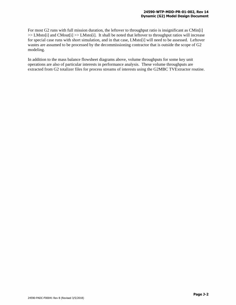
24590-WTP-MDD-PR-01-002, Rev 14 Dynamic (G2) Model Design Document
Page J-2
24590-PADC-F00041 Rev 8 (Revised 3/5/2018)
For most G2 runs with full mission duration, the leftover to throughput ratio is insignificant as CMin[i]
>> LMsto[i] and CMout[i] >> LMsto[i]. It shall be noted that leftover to throughput ratios will increase
for special case runs with short simulation, and in that case, LMsto[i] will need to be assessed. Leftover
wastes are assumed to be processed by the decommissioning contractor that is outside the scope of G2
modeling.
In addition to the mass balance flowsheet diagrams above, volume throughputs for some key unit
operations are also of particular interests in performance analysis. These volume throughputs are
extracted from G2 totalizer files for process streams of interests using the G2MBC TVExtractor routine.

24590-WTP-MDD-PR-01-002, Rev 14 Dynamic (G2) Model Design Document
Page J-3
24590-PADC-F00041 Rev 8 (3/5/2018)
Figure J-1 Mass Balance Flowsheet Diagram (PT-1)
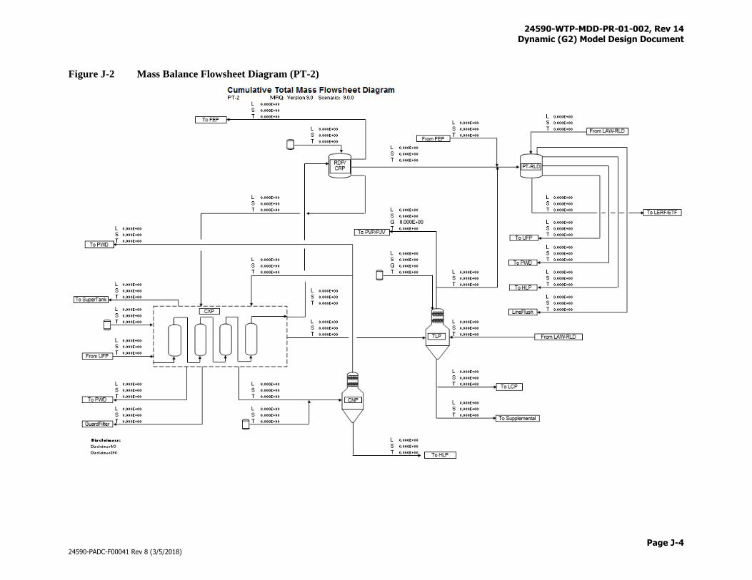
24590-WTP-MDD-PR-01-002, Rev 14 Dynamic (G2) Model Design Document
Page J-4
24590-PADC-F00041 Rev 8 (3/5/2018)
Figure J-2 Mass Balance Flowsheet Diagram (PT-2)
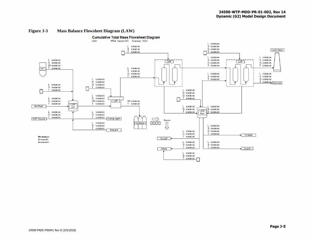
24590-WTP-MDD-PR-01-002, Rev 14 Dynamic (G2) Model Design Document
Page J-5
24590-PADC-F00041 Rev 8 (3/5/2018)
Figure J-3 Mass Balance Flowsheet Diagram (LAW)
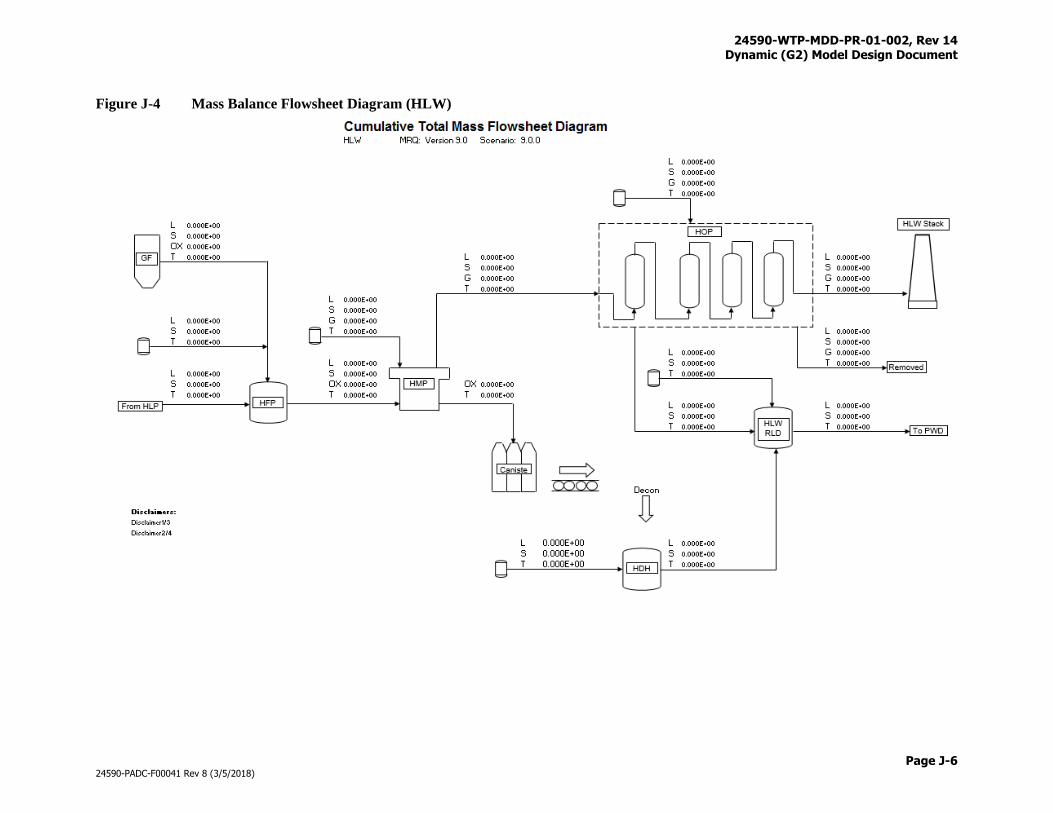
24590-WTP-MDD-PR-01-002, Rev 14 Dynamic (G2) Model Design Document
Page J-6
24590-PADC-F00041 Rev 8 (3/5/2018)
Figure J-4 Mass Balance Flowsheet Diagram (HLW)
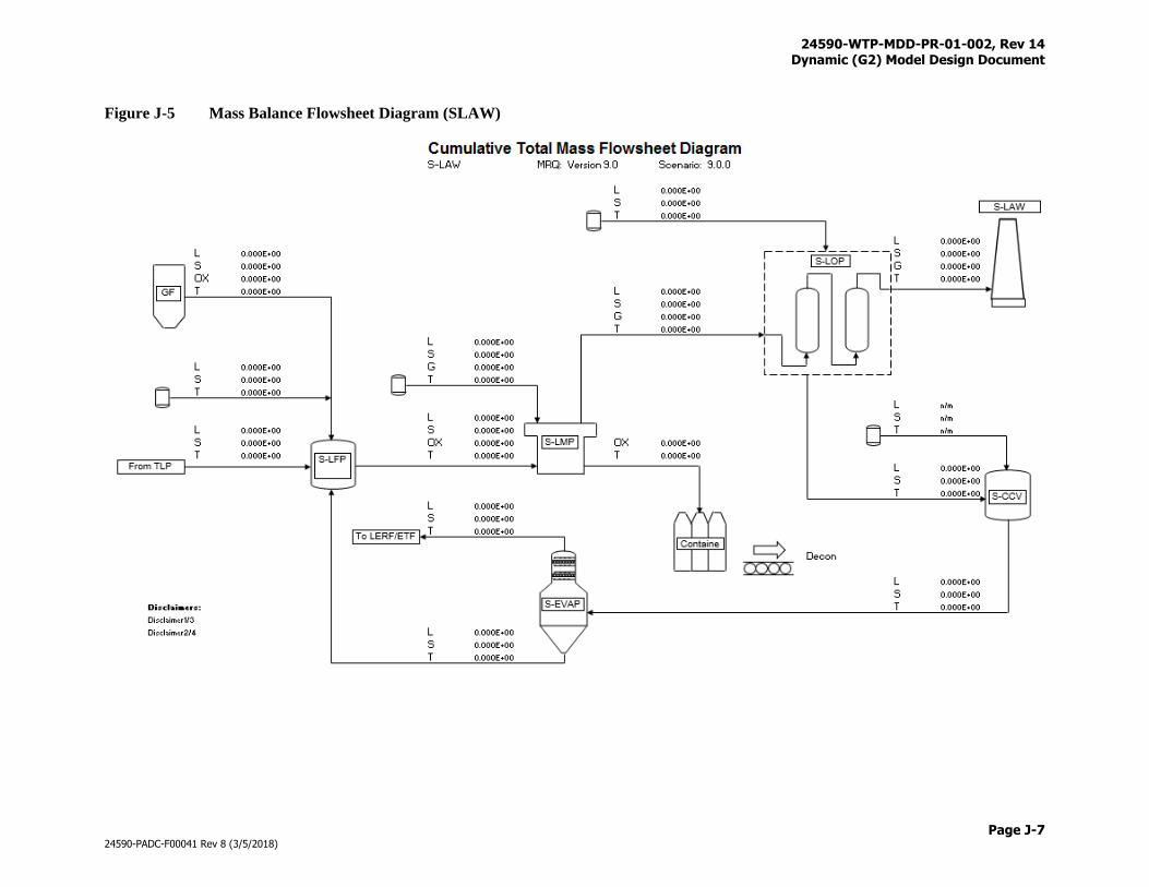
24590-WTP-MDD-PR-01-002, Rev 14 Dynamic (G2) Model Design Document
Page J-7
24590-PADC-F00041 Rev 8 (3/5/2018)
Figure J-5 Mass Balance Flowsheet Diagram (SLAW)
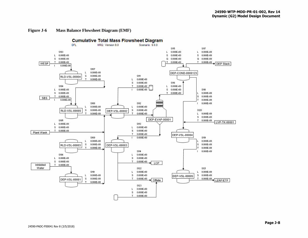
24590-WTP-MDD-PR-01-002, Rev 14 Dynamic (G2) Model Design Document
Page J-8
24590-PADC-F00041 Rev 8 (3/5/2018)
Figure J-6 Mass Balance Flowsheet Diagram (EMF)
24590-WTP-MDD-PR-01-002, Rev 14 Dynamic (G2) Model Design Document
Page K-i
24590-PADC-F00041 Rev 8 (3/5/2018)
Appendix K
Envelope C Reactions
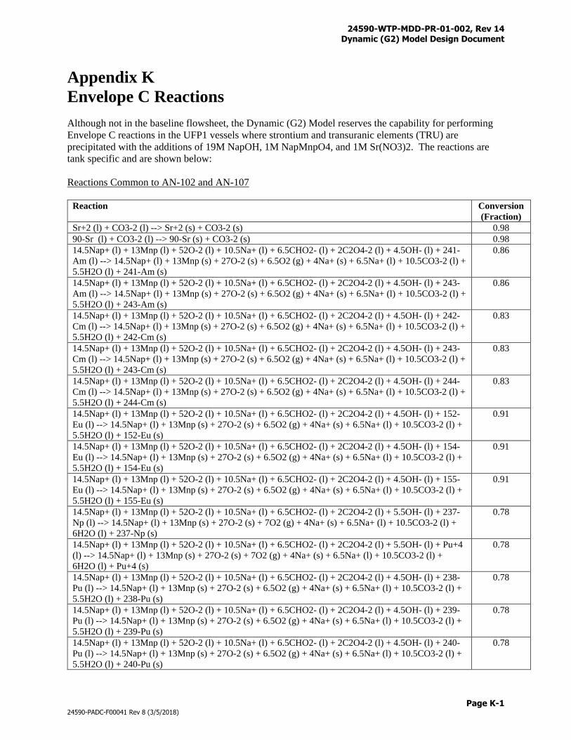
24590-WTP-MDD-PR-01-002, Rev 14 Dynamic (G2) Model Design Document
Page K-1
24590-PADC-F00041 Rev 8 (3/5/2018)
Appendix K
Envelope C Reactions
Although not in the baseline flowsheet, the Dynamic (G2) Model reserves the capability for performing
Envelope C reactions in the UFP1 vessels where strontium and transuranic elements (TRU) are
precipitated with the additions of 19M NapOH, 1M NapMnpO4, and 1M Sr(NO3)2. The reactions are
tank specific and are shown below:
Reactions Common to AN-102 and AN-107
Reaction
Conversion
(Fraction)
Sr+2 (l) + CO3-2 (l) --> Sr+2 (s) + CO3-2 (s) 0.98
90-Sr (l) + CO3-2 (l) --> 90-Sr (s) + CO3-2 (s) 0.98
14.5Nap+ (l) + 13Mnp (l) + 52O-2 (l) + 10.5Na+ (l) + 6.5CHO2- (l) + 2C2O4-2 (l) + 4.5OH- (l) + 241-
Am (l) --> 14.5Nap+ (l) + 13Mnp (s) + 27O-2 (s) + 6.5O2 (g) + 4Na+ (s) + 6.5Na+ (l) + 10.5CO3-2 (l) +
5.5H2O (l) + 241-Am (s)
0.86
14.5Nap+ (l) + 13Mnp (l) + 52O-2 (l) + 10.5Na+ (l) + 6.5CHO2- (l) + 2C2O4-2 (l) + 4.5OH- (l) + 243-
Am (l) --> 14.5Nap+ (l) + 13Mnp (s) + 27O-2 (s) + 6.5O2 (g) + 4Na+ (s) + 6.5Na+ (l) + 10.5CO3-2 (l) +
5.5H2O (l) + 243-Am (s)
0.86
14.5Nap+ (l) + 13Mnp (l) + 52O-2 (l) + 10.5Na+ (l) + 6.5CHO2- (l) + 2C2O4-2 (l) + 4.5OH- (l) + 242-
Cm (l) --> 14.5Nap+ (l) + 13Mnp (s) + 27O-2 (s) + 6.5O2 (g) + 4Na+ (s) + 6.5Na+ (l) + 10.5CO3-2 (l) +
5.5H2O (l) + 242-Cm (s)
0.83
14.5Nap+ (l) + 13Mnp (l) + 52O-2 (l) + 10.5Na+ (l) + 6.5CHO2- (l) + 2C2O4-2 (l) + 4.5OH- (l) + 243-
Cm (l) --> 14.5Nap+ (l) + 13Mnp (s) + 27O-2 (s) + 6.5O2 (g) + 4Na+ (s) + 6.5Na+ (l) + 10.5CO3-2 (l) +
5.5H2O (l) + 243-Cm (s)
0.83
14.5Nap+ (l) + 13Mnp (l) + 52O-2 (l) + 10.5Na+ (l) + 6.5CHO2- (l) + 2C2O4-2 (l) + 4.5OH- (l) + 244-
Cm (l) --> 14.5Nap+ (l) + 13Mnp (s) + 27O-2 (s) + 6.5O2 (g) + 4Na+ (s) + 6.5Na+ (l) + 10.5CO3-2 (l) +
5.5H2O (l) + 244-Cm (s)
0.83
14.5Nap+ (l) + 13Mnp (l) + 52O-2 (l) + 10.5Na+ (l) + 6.5CHO2- (l) + 2C2O4-2 (l) + 4.5OH- (l) + 152-
Eu (l) --> 14.5Nap+ (l) + 13Mnp (s) + 27O-2 (s) + 6.5O2 (g) + 4Na+ (s) + 6.5Na+ (l) + 10.5CO3-2 (l) +
5.5H2O (l) + 152-Eu (s)
0.91
14.5Nap+ (l) + 13Mnp (l) + 52O-2 (l) + 10.5Na+ (l) + 6.5CHO2- (l) + 2C2O4-2 (l) + 4.5OH- (l) + 154-
Eu (l) --> 14.5Nap+ (l) + 13Mnp (s) + 27O-2 (s) + 6.5O2 (g) + 4Na+ (s) + 6.5Na+ (l) + 10.5CO3-2 (l) +
5.5H2O (l) + 154-Eu (s)
0.91
14.5Nap+ (l) + 13Mnp (l) + 52O-2 (l) + 10.5Na+ (l) + 6.5CHO2- (l) + 2C2O4-2 (l) + 4.5OH- (l) + 155-
Eu (l) --> 14.5Nap+ (l) + 13Mnp (s) + 27O-2 (s) + 6.5O2 (g) + 4Na+ (s) + 6.5Na+ (l) + 10.5CO3-2 (l) +
5.5H2O (l) + 155-Eu (s)
0.91
14.5Nap+ (l) + 13Mnp (l) + 52O-2 (l) + 10.5Na+ (l) + 6.5CHO2- (l) + 2C2O4-2 (l) + 5.5OH- (l) + 237-
Np (l) --> 14.5Nap+ (l) + 13Mnp (s) + 27O-2 (s) + 7O2 (g) + 4Na+ (s) + 6.5Na+ (l) + 10.5CO3-2 (l) +
6H2O (l) + 237-Np (s)
0.78
14.5Nap+ (l) + 13Mnp (l) + 52O-2 (l) + 10.5Na+ (l) + 6.5CHO2- (l) + 2C2O4-2 (l) + 5.5OH- (l) + Pu+4
(l) --> 14.5Nap+ (l) + 13Mnp (s) + 27O-2 (s) + 7O2 (g) + 4Na+ (s) + 6.5Na+ (l) + 10.5CO3-2 (l) +
6H2O (l) + Pu+4 (s)
0.78
14.5Nap+ (l) + 13Mnp (l) + 52O-2 (l) + 10.5Na+ (l) + 6.5CHO2- (l) + 2C2O4-2 (l) + 4.5OH- (l) + 238-
Pu (l) --> 14.5Nap+ (l) + 13Mnp (s) + 27O-2 (s) + 6.5O2 (g) + 4Na+ (s) + 6.5Na+ (l) + 10.5CO3-2 (l) +
5.5H2O (l) + 238-Pu (s)
0.78
14.5Nap+ (l) + 13Mnp (l) + 52O-2 (l) + 10.5Na+ (l) + 6.5CHO2- (l) + 2C2O4-2 (l) + 4.5OH- (l) + 239-
Pu (l) --> 14.5Nap+ (l) + 13Mnp (s) + 27O-2 (s) + 6.5O2 (g) + 4Na+ (s) + 6.5Na+ (l) + 10.5CO3-2 (l) +
5.5H2O (l) + 239-Pu (s)
0.78
14.5Nap+ (l) + 13Mnp (l) + 52O-2 (l) + 10.5Na+ (l) + 6.5CHO2- (l) + 2C2O4-2 (l) + 4.5OH- (l) + 240-
Pu (l) --> 14.5Nap+ (l) + 13Mnp (s) + 27O-2 (s) + 6.5O2 (g) + 4Na+ (s) + 6.5Na+ (l) + 10.5CO3-2 (l) +
5.5H2O (l) + 240-Pu (s)
0.78
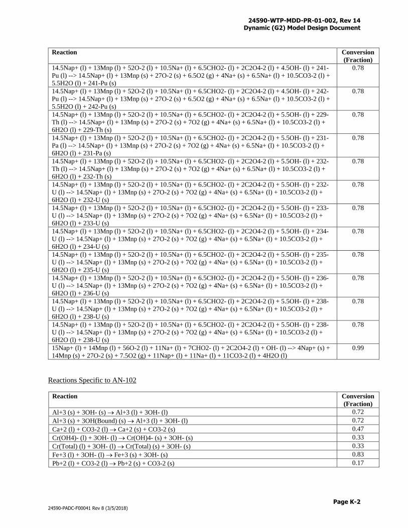
24590-WTP-MDD-PR-01-002, Rev 14 Dynamic (G2) Model Design Document
Page K-2
24590-PADC-F00041 Rev 8 (3/5/2018)
Reaction
Conversion
(Fraction)
14.5Nap+ (l) + 13Mnp (l) + 52O-2 (l) + 10.5Na+ (l) + 6.5CHO2- (l) + 2C2O4-2 (l) + 4.5OH- (l) + 241-
Pu (l) --> 14.5Nap+ (l) + 13Mnp (s) + 27O-2 (s) + 6.5O2 (g) + 4Na+ (s) + 6.5Na+ (l) + 10.5CO3-2 (l) +
5.5H2O (l) + 241-Pu (s)
0.78
14.5Nap+ (l) + 13Mnp (l) + 52O-2 (l) + 10.5Na+ (l) + 6.5CHO2- (l) + 2C2O4-2 (l) + 4.5OH- (l) + 242-
Pu (l) --> 14.5Nap+ (l) + 13Mnp (s) + 27O-2 (s) + 6.5O2 (g) + 4Na+ (s) + 6.5Na+ (l) + 10.5CO3-2 (l) +
5.5H2O (l) + 242-Pu (s)
0.78
14.5Nap+ (l) + 13Mnp (l) + 52O-2 (l) + 10.5Na+ (l) + 6.5CHO2- (l) + 2C2O4-2 (l) + 5.5OH- (l) + 229-
Th (l) --> 14.5Nap+ (l) + 13Mnp (s) + 27O-2 (s) + 7O2 (g) + 4Na+ (s) + 6.5Na+ (l) + 10.5CO3-2 (l) +
6H2O (l) + 229-Th (s)
0.78
14.5Nap+ (l) + 13Mnp (l) + 52O-2 (l) + 10.5Na+ (l) + 6.5CHO2- (l) + 2C2O4-2 (l) + 5.5OH- (l) + 231-
Pa (l) --> 14.5Nap+ (l) + 13Mnp (s) + 27O-2 (s) + 7O2 (g) + 4Na+ (s) + 6.5Na+ (l) + 10.5CO3-2 (l) +
6H2O (l) + 231-Pa (s)
0.78
14.5Nap+ (l) + 13Mnp (l) + 52O-2 (l) + 10.5Na+ (l) + 6.5CHO2- (l) + 2C2O4-2 (l) + 5.5OH- (l) + 232-
Th (l) --> 14.5Nap+ (l) + 13Mnp (s) + 27O-2 (s) + 7O2 (g) + 4Na+ (s) + 6.5Na+ (l) + 10.5CO3-2 (l) +
6H2O (l) + 232-Th (s)
0.78
14.5Nap+ (l) + 13Mnp (l) + 52O-2 (l) + 10.5Na+ (l) + 6.5CHO2- (l) + 2C2O4-2 (l) + 5.5OH- (l) + 232-
U (l) --> 14.5Nap+ (l) + 13Mnp (s) + 27O-2 (s) + 7O2 (g) + 4Na+ (s) + 6.5Na+ (l) + 10.5CO3-2 (l) +
6H2O (l) + 232-U (s)
0.78
14.5Nap+ (l) + 13Mnp (l) + 52O-2 (l) + 10.5Na+ (l) + 6.5CHO2- (l) + 2C2O4-2 (l) + 5.5OH- (l) + 233-
U (l) --> 14.5Nap+ (l) + 13Mnp (s) + 27O-2 (s) + 7O2 (g) + 4Na+ (s) + 6.5Na+ (l) + 10.5CO3-2 (l) +
6H2O (l) + 233-U (s)
0.78
14.5Nap+ (l) + 13Mnp (l) + 52O-2 (l) + 10.5Na+ (l) + 6.5CHO2- (l) + 2C2O4-2 (l) + 5.5OH- (l) + 234-
U (l) --> 14.5Nap+ (l) + 13Mnp (s) + 27O-2 (s) + 7O2 (g) + 4Na+ (s) + 6.5Na+ (l) + 10.5CO3-2 (l) +
6H2O (l) + 234-U (s)
0.78
14.5Nap+ (l) + 13Mnp (l) + 52O-2 (l) + 10.5Na+ (l) + 6.5CHO2- (l) + 2C2O4-2 (l) + 5.5OH- (l) + 235-
U (l) --> 14.5Nap+ (l) + 13Mnp (s) + 27O-2 (s) + 7O2 (g) + 4Na+ (s) + 6.5Na+ (l) + 10.5CO3-2 (l) +
6H2O (l) + 235-U (s)
0.78
14.5Nap+ (l) + 13Mnp (l) + 52O-2 (l) + 10.5Na+ (l) + 6.5CHO2- (l) + 2C2O4-2 (l) + 5.5OH- (l) + 236-
U (l) --> 14.5Nap+ (l) + 13Mnp (s) + 27O-2 (s) + 7O2 (g) + 4Na+ (s) + 6.5Na+ (l) + 10.5CO3-2 (l) +
6H2O (l) + 236-U (s)
0.78
14.5Nap+ (l) + 13Mnp (l) + 52O-2 (l) + 10.5Na+ (l) + 6.5CHO2- (l) + 2C2O4-2 (l) + 5.5OH- (l) + 238-
U (l) --> 14.5Nap+ (l) + 13Mnp (s) + 27O-2 (s) + 7O2 (g) + 4Na+ (s) + 6.5Na+ (l) + 10.5CO3-2 (l) +
6H2O (l) + 238-U (s)
0.78
14.5Nap+ (l) + 13Mnp (l) + 52O-2 (l) + 10.5Na+ (l) + 6.5CHO2- (l) + 2C2O4-2 (l) + 5.5OH- (l) + 238-
U (l) --> 14.5Nap+ (l) + 13Mnp (s) + 27O-2 (s) + 7O2 (g) + 4Na+ (s) + 6.5Na+ (l) + 10.5CO3-2 (l) +
6H2O (l) + 238-U (s)
0.78
15Nap+ (l) + 14Mnp (l) + 56O-2 (l) + 11Na+ (l) + 7CHO2- (l) + 2C2O4-2 (l) + OH- (l) --> 4Nap+ (s) +
14Mnp (s) + 27O-2 (s) + 7.5O2 (g) + 11Nap+ (l) + 11Na+ (l) + 11CO3-2 (l) + 4H2O (l)
0.99
Reactions Specific to AN-102
Reaction Conversion
(Fraction)
Al+3 (s) + 3OH- (s) Al+3 (l) + 3OH- (l) 0.72
Al+3 (s) + 3OH(Bound) (s) Al+3 (l) + 3OH- (l) 0.72
Ca+2 (l) + CO3-2 (l) Ca+2 (s) + CO3-2 (s) 0.47
Cr(OH4)- (l) + 3OH- (l) Cr(OH)4- (s) + 3OH- (s) 0.33
Cr(Total) (l) + 3OH- (l) Cr(Total) (s) + 3OH- (s) 0.33
Fe+3 (l) + 3OH- (l) Fe+3 (s) + 3OH- (s) 0.83
Pb+2 (l) + CO3-2 (l) Pb+2 (s) + CO3-2 (s) 0.17
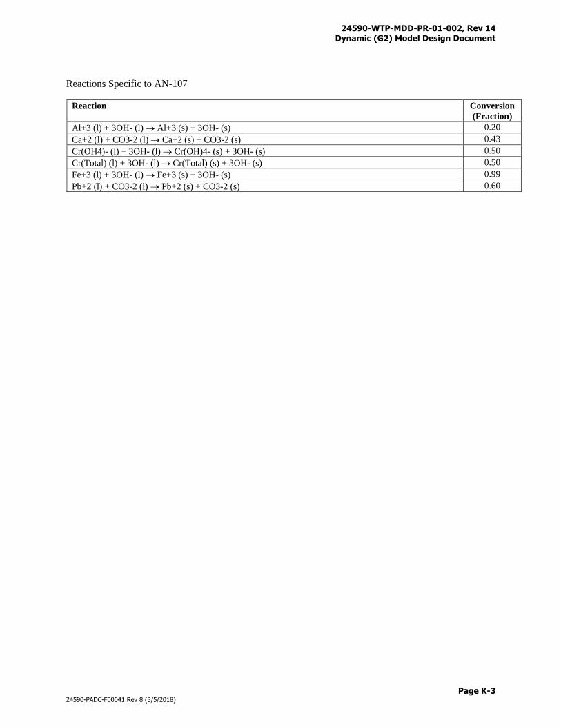
24590-WTP-MDD-PR-01-002, Rev 14 Dynamic (G2) Model Design Document
Page K-3
24590-PADC-F00041 Rev 8 (3/5/2018)
Reactions Specific to AN-107
Reaction Conversion
(Fraction)
Al+3 (l) + 3OH- (l) Al+3 (s) + 3OH- (s) 0.20
Ca+2 (l) + CO3-2 (l) Ca+2 (s) + CO3-2 (s) 0.43
Cr(OH4)- (l) + 3OH- (l) Cr(OH)4- (s) + 3OH- (s) 0.50
Cr(Total) (l) + 3OH- (l) Cr(Total) (s) + 3OH- (s) 0.50
Fe+3 (l) + 3OH- (l) Fe+3 (s) + 3OH- (s) 0.99
Pb+2 (l) + CO3-2 (l) Pb+2 (s) + CO3-2 (s) 0.60

24590-WTP-MDD-PR-01-002, Rev 14 Dynamic (G2) Model Design Document
Page L-i
24590-PADC-F00041 Rev 8 (3/5/2018)
Appendix L
UFP2 Leaching with Boehmite
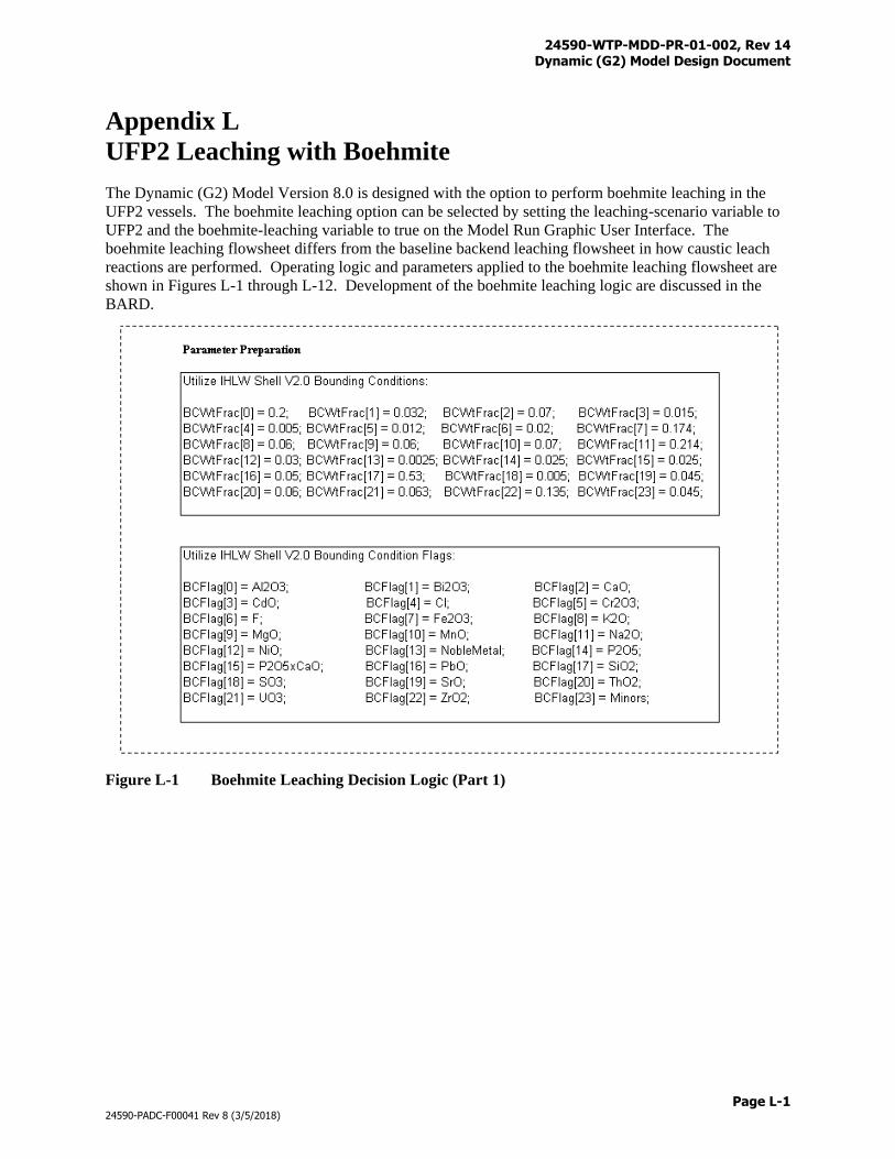
24590-WTP-MDD-PR-01-002, Rev 14 Dynamic (G2) Model Design Document
Page L-1
24590-PADC-F00041 Rev 8 (3/5/2018)
Appendix L
UFP2 Leaching with Boehmite
The Dynamic (G2) Model Version 8.0 is designed with the option to perform boehmite leaching in the
UFP2 vessels. The boehmite leaching option can be selected by setting the leaching-scenario variable to
UFP2 and the boehmite-leaching variable to true on the Model Run Graphic User Interface. The
boehmite leaching flowsheet differs from the baseline backend leaching flowsheet in how caustic leach
reactions are performed. Operating logic and parameters applied to the boehmite leaching flowsheet are
shown in Figures L-1 through L-12. Development of the boehmite leaching logic are discussed in the
BARD.
Figure L-1 Boehmite Leaching Decision Logic (Part 1)
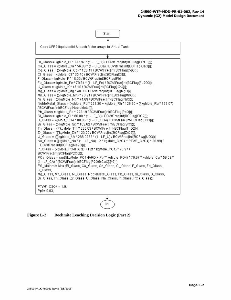
24590-WTP-MDD-PR-01-002, Rev 14 Dynamic (G2) Model Design Document
Page L-2
24590-PADC-F00041 Rev 8 (3/5/2018)
Figure L-2 Boehmite Leaching Decision Logic (Part 2)
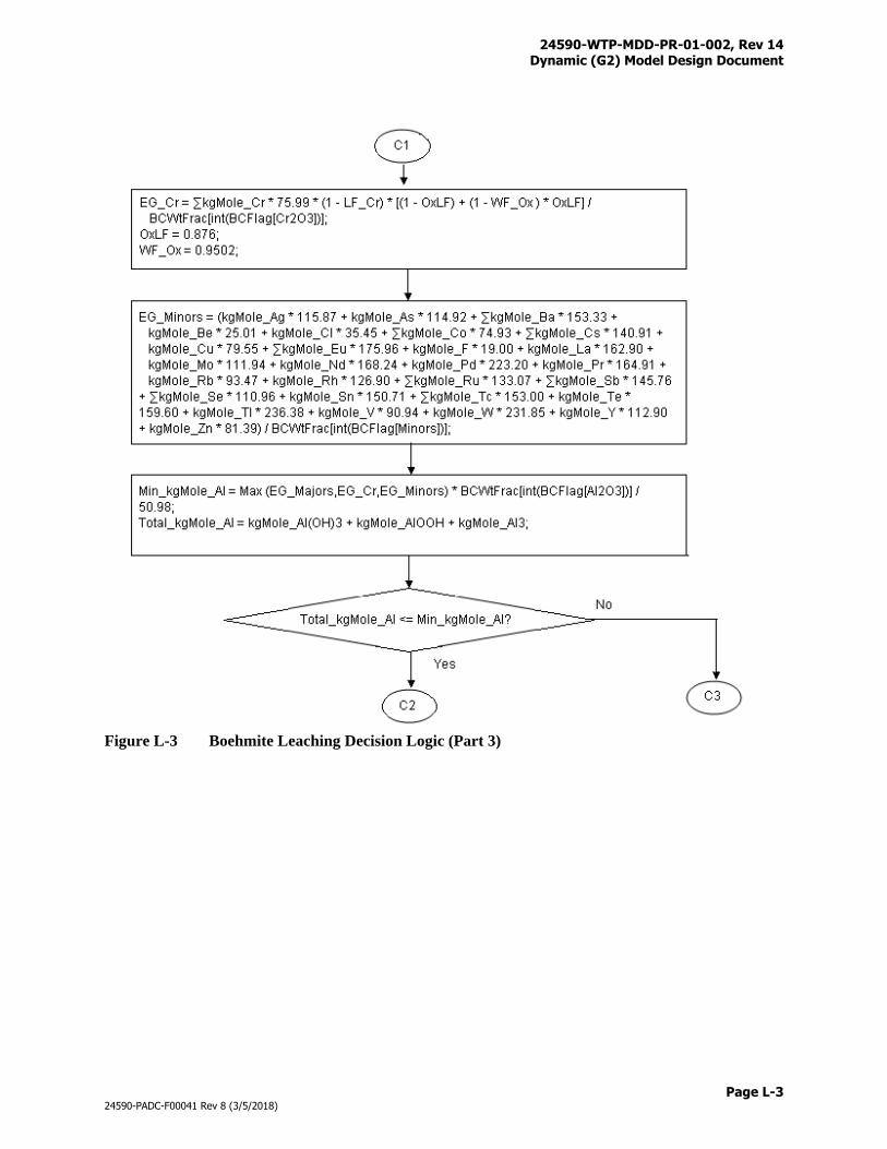
24590-WTP-MDD-PR-01-002, Rev 14 Dynamic (G2) Model Design Document
Page L-3
24590-PADC-F00041 Rev 8 (3/5/2018)
Figure L-3 Boehmite Leaching Decision Logic (Part 3)
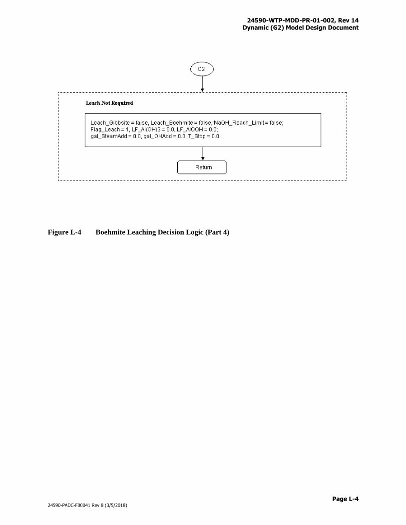
24590-WTP-MDD-PR-01-002, Rev 14 Dynamic (G2) Model Design Document
Page L-4
24590-PADC-F00041 Rev 8 (3/5/2018)
Figure L-4 Boehmite Leaching Decision Logic (Part 4)
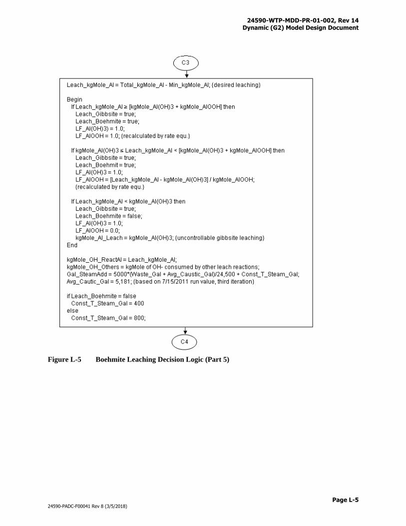
24590-WTP-MDD-PR-01-002, Rev 14 Dynamic (G2) Model Design Document
Page L-5
24590-PADC-F00041 Rev 8 (3/5/2018)
Figure L-5 Boehmite Leaching Decision Logic (Part 5)
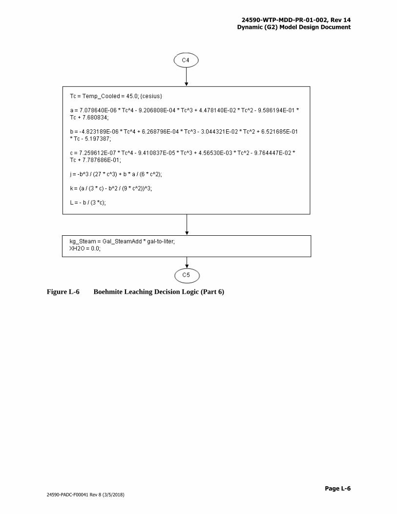
24590-WTP-MDD-PR-01-002, Rev 14 Dynamic (G2) Model Design Document
Page L-6
24590-PADC-F00041 Rev 8 (3/5/2018)
Figure L-6 Boehmite Leaching Decision Logic (Part 6)
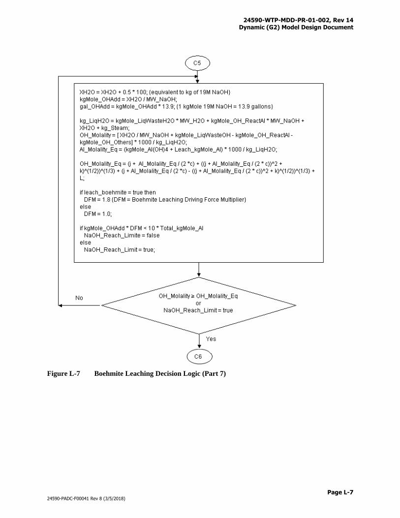
24590-WTP-MDD-PR-01-002, Rev 14 Dynamic (G2) Model Design Document
Page L-7
24590-PADC-F00041 Rev 8 (3/5/2018)
Figure L-7 Boehmite Leaching Decision Logic (Part 7)
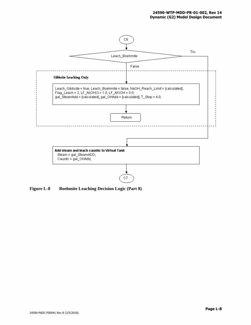
24590-WTP-MDD-PR-01-002, Rev 14 Dynamic (G2) Model Design Document
Page L-8
24590-PADC-F00041 Rev 8 (3/5/2018)
Figure L-8 Boehmite Leaching Decision Logic (Part 8)
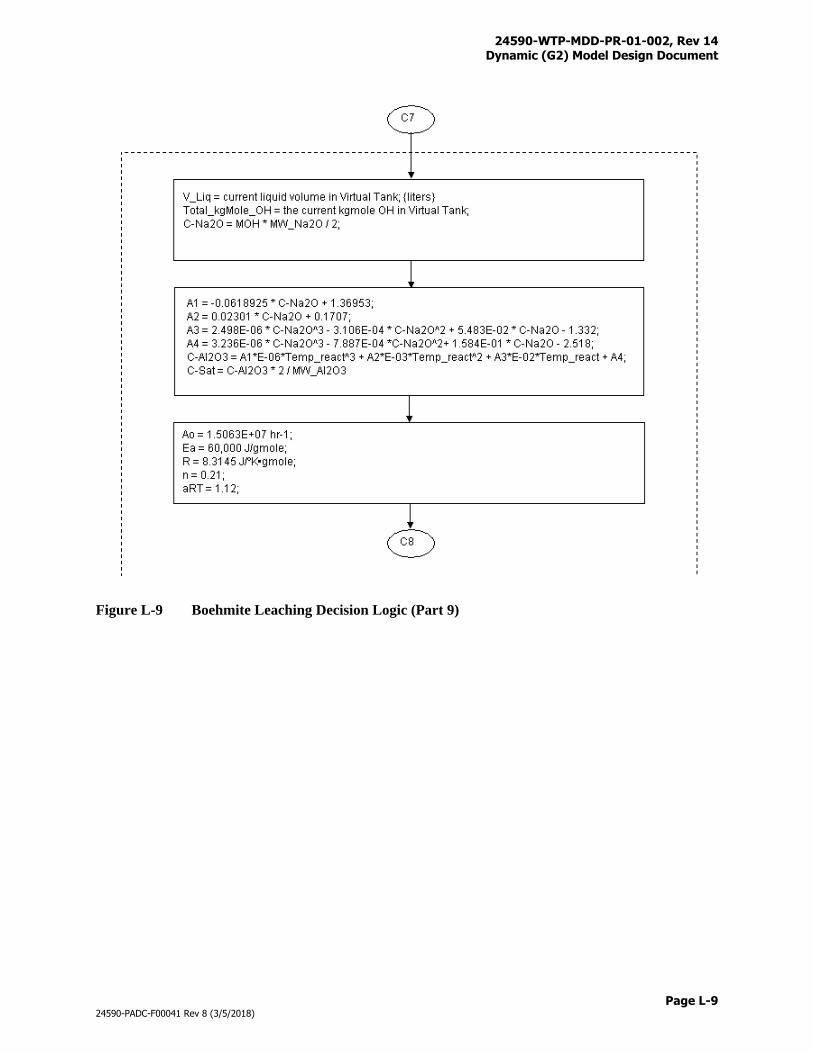
24590-WTP-MDD-PR-01-002, Rev 14 Dynamic (G2) Model Design Document
Page L-9
24590-PADC-F00041 Rev 8 (3/5/2018)
Figure L-9 Boehmite Leaching Decision Logic (Part 9)
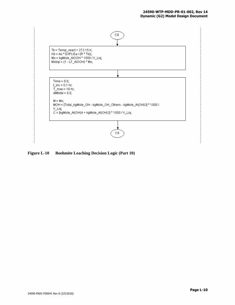
24590-WTP-MDD-PR-01-002, Rev 14 Dynamic (G2) Model Design Document
Page L-10
24590-PADC-F00041 Rev 8 (3/5/2018)
Figure L-10 Boehmite Leaching Decision Logic (Part 10)
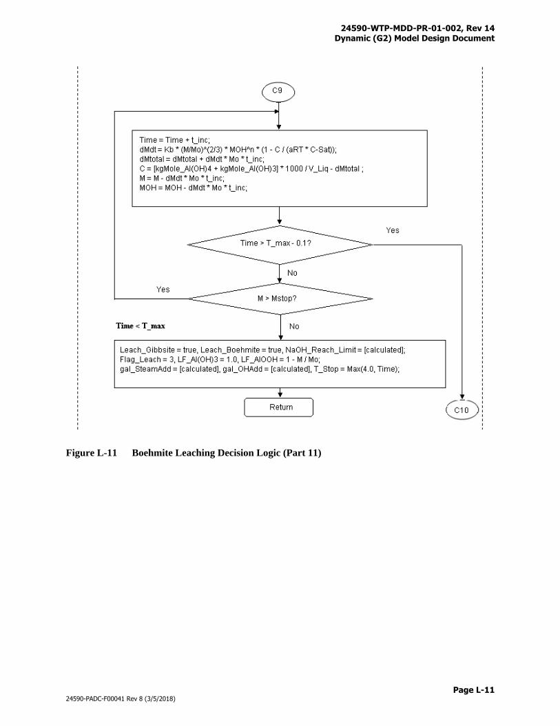
24590-WTP-MDD-PR-01-002, Rev 14 Dynamic (G2) Model Design Document
Page L-11
24590-PADC-F00041 Rev 8 (3/5/2018)
Figure L-11 Boehmite Leaching Decision Logic (Part 11)
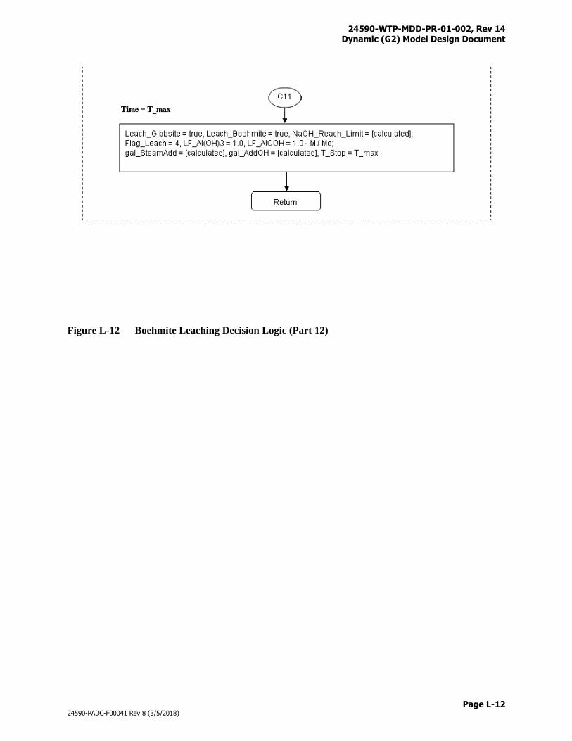
24590-WTP-MDD-PR-01-002, Rev 14 Dynamic (G2) Model Design Document
Page L-12
24590-PADC-F00041 Rev 8 (3/5/2018)
Figure L-12 Boehmite Leaching Decision Logic (Part 12)

24590-WTP-MDD-PR-01-002, Rev 14 Dynamic (G2) Model Design Document
Page M-i
24590-PADC-F00041 Rev 8 (3/5/2018)
Appendix M
UFP1 Leaching with Gibbsite
24590-WTP-MDD-PR-01-002, Rev 14 Dynamic (G2) Model Design Document
Page M-1
24590-PADC-F00041 Rev 8 (3/5/2018)
Appendix M
UFP1 Leaching with Gibbsite
The Dynamic (G2) Model Version 8.0 is designed with the option to perform caustic leach in the UFP1
vessels (upfront leaching) which can be selected by setting the leaching-scenario variable to UFP1 on the
Model Run Graphic User Interface. The upfront leaching flowsheet differs from the baseline backend
leaching flowsheet primary in where caustic leach reactions are performed, but also in feed blending,
recycle handling, and solid processes. Operating logic and parameters applied to the upfront leaching
flowsheet are described as follows:
Recycle Handling
When the frontend leaching operations are chosen, HLP-VSL-00027A is configured to only receive,
store, and transfer FEP evaporator concentrates. A contingent volume is set between the lower set point
and the upper set point. The vessel can be discharged when its volume is above the lower set point. The
vessel can receive and discharge when its volume is within the contingency zone. HLP-VSL-00027A can
only be discharged when its volume is above the upper set point. The recycle concentrate in this vessel is
used for the feed blending operations described below in this Appendix.
Feed Blending
Feed blending logic are implemented in the UFP1 vessels to: a) improve the uniformity of ultrafiltration
feeds, b) better balance the overall utilization of LAW and HLW feeds, and c) alleviate the pressure of
water lock on the recycle loop. Normal feed blending is performed by filling a UFP1 vessel with a pre-
determined volume of HLW feed then topping it off with recycled concentrate or LAW feed. Other feed
blendings include those described below:
1) When a UFP1 vessel becomes “empty”, it will receive feeds from upstream sources in the following
order: a) HLW feed from HLP-VSL-00022, b) recycle concentrate from HLP-VSL-00027A, or c)
LAW feed from FRP-VSL-00002A/B/C/D. It will use the next priority feed if the higher priority feed
is not available at the time of request.
2) When HLW feed is delivered to the UFP1 vessel, the mass of gibbsite will be determined. The
transfer will stop if 25 kg-moles of Al(OH)3 has been accumulated in the vessel which will then be
topped off to its set volume with recycle concentrate or LAW feed. The set volume of the UFP1
vessel is 28,300 gallons.
3) The UFP1 vessel will be filled with HLW feed to its set volume if the 25 kg-moles of Al(OH)3 goal
is not reached. When this happens, topping off the vessel with recycle concentrate or LAW feed is
not required.
4) If the UFP1 vessel reaches the 25 kg-mole Al(OH)3 goal before it fills to the set volume and no
recycle concentrate and LAW feed are available at the time, the UFP1 vessel will be set to perform
the caustic leach operations.
5) To achieve a better balance for the use of LAW and HLW feeds, a LAW batch will be sent through
the UFP system without blending in the beginning of each UFP2 cycle. The LAW feed will be
transferred to the available UFP1 vessel to its set volume.
6) To alleviate the pressure of water lock on the recycle loop, an upper set volume is placed in HLP-
VSL-00027A at 84,584 gallons, when reached will trigger a discharge, e.g., the next available UFP1
vessel will receive a full batch of recycle concentrate.
24590-WTP-MDD-PR-01-002, Rev 14 Dynamic (G2) Model Design Document
Page M-2
24590-PADC-F00041 Rev 8 (3/5/2018)
Line flush is received in the UFP1 vessel after each batch transfer from HLP-VSL-00022, HLP-VSL-
00027A, or FRP-VSL-00002A/B/C/D. Caustic leach decisions will be made based on the waste
compositions in the vessel.
Caustic Leach
Generally caustic leach can reduce the HLW glass produced as most of the WTP solids are aluminum
limiting. For waste batches that are limited by other Specification 1 species, caustic leach is unnecessary
as it increases processing time and add sodium to the plant. A caustic leach decision logic has been
developed by the flowsheet engineers that determines if a waste batch is aluminum limiting and
consequently if the caustic leach can reduce HLW glass by 10% or more. Wash factors as well as the
subsequent oxidative leach have also been considered. Figures 5 through 8 in Section 4.8.3 provide a
logic diagram that determines if caustic leach is required for the waste batch. The following actions could
take place depending on the caustic leach decisions:
1) The feed will be heated, caustic leached, and cooled, or
2) The feed will be adjusted for sodium concentration by dilution and hydroxide concentration by
caustic addition.
Caustic leach operations include heating, reaction, and cooling. A pre-determined volume of 19M NaOH
(Na = waste sodium) will also be added during heating. Vessel contents will be heated to 85 oC with a
steam condensate volume and a heating time determined by Equations L-1 and L-2, respectively.
VS = 9,000 * (VW + VACV) / 39,000 (Eq. L-1)
TH = 9 * (VW + VACV) / 39,000 (Eq. L-2)
Where:
VS = Steam condensate volume (gallons)
VW = Waste volume before heating (gallons)
VACV = Average caustic volume (gallons)
TH = Heating time (hours)
The average caustic volume (2,133 gallons) is obtained by averaging the values for the entire mission
from a trial run. The caustic volume for leaching is determined based on Equation 13 with an additional
10% margin to account for dilution later during wash. The heated solutions are allowed to react for 8
hours during which an additional 400 gallons of steam condensate is added to maintain temperature.
Leaching reactions are the same as those discussed in the backend leaching flowsheet in Section 4.8.3.
Cooling takes 2 hours. Steam and chill water supply can support parallel heating and parallel cooling
operations in the two UFP1 vessels.
For waste batches not requiring caustic leach, water will be added if necessary to lower sodium
concentration to 6M. Caustic (19M) will also be added if necessary to keep hydroxide concentration to
above 0.5M. Vessel contents will be heated to 45 oC with a steam condensate volume and a heating time
determined by Equations 26 and 27, respectively. Solubility is applied at 45 oC after pre-heating.
Solid Processes
24590-WTP-MDD-PR-01-002, Rev 14 Dynamic (G2) Model Design Document
Page M-3
24590-PADC-F00041 Rev 8 (3/5/2018)
Set volumes of the UFP2 vessels are placed at 19,000 gallons, e.g., solid concentratin is achieved in an
1000-gallon increment between 18,000 – 19,000 gallons. Solid concentration stops when the 20 wt%
target value is reached. Solid wash, oxidative leach, and oxidative wash processes are the same as those
backend leaching flowsheet, but treated solids can only be discharged to HLP-VSL-00027B.
24590-WTP-MDD-PR-01-002, Rev 14 Dynamic (G2) Model Design Document
Page N-i
24590-PADC-F00041 Rev 8 (3/5/2018)
Appendix N
Totalizer Files
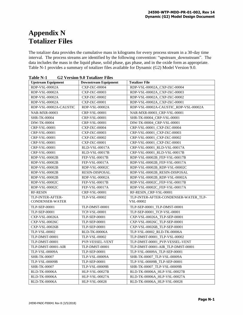
24590-WTP-MDD-PR-01-002, Rev 14 Dynamic (G2) Model Design Document
Page N-1
24590-PADC-F00041 Rev 8 (3/5/2018)
Appendix N
Totalizer Files
The totalizer data provides the cumulative mass in kilograms for every process stream in a 30-day time
interval. The process streams are identified by the following convention: “upstream_downstream”. The
data includes the mass in the liquid phase, solid phase, gas phase, and in the oxide form as appropriate.
Table N-1 provides a summary of totalizer files available for Dynamic (G2) Model Version 9.0.
Table N-1 G2 Version 9.0 Totalizer Files Upstream Equipment Downstream Equipment Totalizer File
RDP-VSL-00002A CXP-IXC-00004 RDP-VSL-00002A_CXP-IXC-00004
RDP-VSL-00002A CXP-IXC-00003 RDP-VSL-00002A_CXP-IXC-00003
RDP-VSL-00002A CXP-IXC-00002 RDP-VSL-00002A_CXP-IXC-00002
RDP-VSL-00002A CXP-IXC-00001 RDP-VSL-00002A_CXP-IXC-00001
RDP-VSL-00002A-CAUSTIC RDP-VSL-00002A RDP-VSL-00002A-CAUSTIC_RDP-VSL-00002A
NAR-MXR-00003 CRP-VSL-00001 NAR-MXR-00003_CRP-VSL-00001
SHR-TK-00004 CRP-VSL-00001 SHR-TK-00004_CRP-VSL-00001
DIW-TK-00004 CRP-VSL-00001 DIW-TK-00004_CRP-VSL-00001
CRP-VSL-00001 CXP-IXC-00004 CRP-VSL-00001_CXP-IXC-00004
CRP-VSL-00001 CXP-IXC-00003 CRP-VSL-00001_CXP-IXC-00003
CRP-VSL-00001 CXP-IXC-00002 CRP-VSL-00001_CXP-IXC-00002
CRP-VSL-00001 CXP-IXC-00001 CRP-VSL-00001_CXP-IXC-00001
CRP-VSL-00001 RLD-VSL-00017A CRP-VSL-00001_RLD-VSL-00017A
CRP-VSL-00001 RLD-VSL-00017B CRP-VSL-00001_RLD-VSL-00017B
RDP-VSL-00002B FEP-VSL-00017B RDP-VSL-00002B_FEP-VSL-00017B
RDP-VSL-00002B FEP-VSL-00017A RDP-VSL-00002B_FEP-VSL-00017A
RDP-VSL-00002B RDP-VSL-00002C RDP-VSL-00002B_RDP-VSL-00002C
RDP-VSL-00002B RESIN-DISPOSAL RDP-VSL-00002B_RESIN-DISPOSAL
RDP-VSL-00002B RDP-VSL-00002A RDP-VSL-00002B_RDP-VSL-00002A
RDP-VSL-00002C FEP-VSL-00017B RDP-VSL-00002C_FEP-VSL-00017B
RDP-VSL-00002C FEP-VSL-00017A RDP-VSL-00002C_FEP-VSL-00017A
RF-RESIN CRP-VSL-00001 RF-RESIN_CRP-VSL-00001
TLP-INTER-AFTER-
CONDENSER-WATER
TLP-VSL-00002 TLP-INTER-AFTER-CONDENSER-WATER_TLP-
VSL-00002
TLP-SEP-00001 TLP-DMST-00001 TLP-SEP-00001_TLP-DMST-00001
TLP-SEP-00001 TCP-VSL-00001 TLP-SEP-00001_TCP-VSL-00001
CXP-VSL-00026A TLP-SEP-00001 CXP-VSL-00026A_TLP-SEP-00001
CXP-VSL-00026C TLP-SEP-00001 CXP-VSL-00026C_TLP-SEP-00001
CXP-VSL-00026B TLP-SEP-00001 CXP-VSL-00026B_TLP-SEP-00001
TLP-VSL-00002 RLD-TK-00006A TLP-VSL-00002_RLD-TK-00006A
TLP-DMST-00001 TLP-VSL-00002 TLP-DMST-00001_TLP-VSL-00002
TLP-DMST-00001 PVP-VESSEL-VENT TLP-DMST-00001_PVP-VESSEL-VENT
TLP-DMST-00001-AIR TLP-DMST-00001 TLP-DMST-00001-AIR_TLP-DMST-00001
TLP-VSL-00009A TLP-SEP-00001 TLP-VSL-00009A_TLP-SEP-00001
SHR-TK-00007 TLP-VSL-00009A SHR-TK-00007_TLP-VSL-00009A
TLP-VSL-00009B TLP-SEP-00001 TLP-VSL-00009B_TLP-SEP-00001
SHR-TK-00007 TLP-VSL-00009B SHR-TK-00007_TLP-VSL-00009B
RLD-TK-00006A HLP-VSL-00027B RLD-TK-00006A_HLP-VSL-00027B
RLD-TK-00006A HLP-VSL-00027A RLD-TK-00006A_HLP-VSL-00027A
RLD-TK-00006A HLP-VSL-00028 RLD-TK-00006A_HLP-VSL-00028
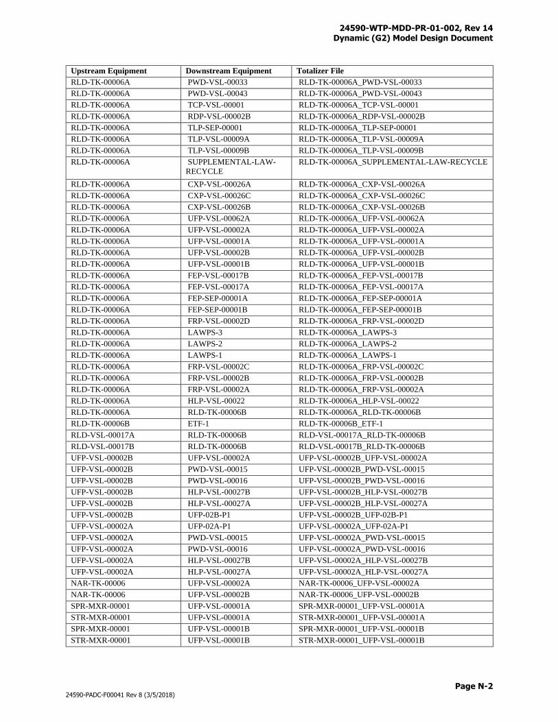
24590-WTP-MDD-PR-01-002, Rev 14 Dynamic (G2) Model Design Document
Page N-2
24590-PADC-F00041 Rev 8 (3/5/2018)
Upstream Equipment Downstream Equipment Totalizer File
RLD-TK-00006A PWD-VSL-00033 RLD-TK-00006A_PWD-VSL-00033
RLD-TK-00006A PWD-VSL-00043 RLD-TK-00006A_PWD-VSL-00043
RLD-TK-00006A TCP-VSL-00001 RLD-TK-00006A_TCP-VSL-00001
RLD-TK-00006A RDP-VSL-00002B RLD-TK-00006A_RDP-VSL-00002B
RLD-TK-00006A TLP-SEP-00001 RLD-TK-00006A_TLP-SEP-00001
RLD-TK-00006A TLP-VSL-00009A RLD-TK-00006A_TLP-VSL-00009A
RLD-TK-00006A TLP-VSL-00009B RLD-TK-00006A_TLP-VSL-00009B
RLD-TK-00006A SUPPLEMENTAL-LAW-
RECYCLE
RLD-TK-00006A_SUPPLEMENTAL-LAW-RECYCLE
RLD-TK-00006A CXP-VSL-00026A RLD-TK-00006A_CXP-VSL-00026A
RLD-TK-00006A CXP-VSL-00026C RLD-TK-00006A_CXP-VSL-00026C
RLD-TK-00006A CXP-VSL-00026B RLD-TK-00006A_CXP-VSL-00026B
RLD-TK-00006A UFP-VSL-00062A RLD-TK-00006A_UFP-VSL-00062A
RLD-TK-00006A UFP-VSL-00002A RLD-TK-00006A_UFP-VSL-00002A
RLD-TK-00006A UFP-VSL-00001A RLD-TK-00006A_UFP-VSL-00001A
RLD-TK-00006A UFP-VSL-00002B RLD-TK-00006A_UFP-VSL-00002B
RLD-TK-00006A UFP-VSL-00001B RLD-TK-00006A_UFP-VSL-00001B
RLD-TK-00006A FEP-VSL-00017B RLD-TK-00006A_FEP-VSL-00017B
RLD-TK-00006A FEP-VSL-00017A RLD-TK-00006A_FEP-VSL-00017A
RLD-TK-00006A FEP-SEP-00001A RLD-TK-00006A_FEP-SEP-00001A
RLD-TK-00006A FEP-SEP-00001B RLD-TK-00006A_FEP-SEP-00001B
RLD-TK-00006A FRP-VSL-00002D RLD-TK-00006A_FRP-VSL-00002D
RLD-TK-00006A LAWPS-3 RLD-TK-00006A_LAWPS-3
RLD-TK-00006A LAWPS-2 RLD-TK-00006A_LAWPS-2
RLD-TK-00006A LAWPS-1 RLD-TK-00006A_LAWPS-1
RLD-TK-00006A FRP-VSL-00002C RLD-TK-00006A_FRP-VSL-00002C
RLD-TK-00006A FRP-VSL-00002B RLD-TK-00006A_FRP-VSL-00002B
RLD-TK-00006A FRP-VSL-00002A RLD-TK-00006A_FRP-VSL-00002A
RLD-TK-00006A HLP-VSL-00022 RLD-TK-00006A_HLP-VSL-00022
RLD-TK-00006A RLD-TK-00006B RLD-TK-00006A_RLD-TK-00006B
RLD-TK-00006B ETF-1 RLD-TK-00006B_ETF-1
RLD-VSL-00017A RLD-TK-00006B RLD-VSL-00017A_RLD-TK-00006B
RLD-VSL-00017B RLD-TK-00006B RLD-VSL-00017B_RLD-TK-00006B
UFP-VSL-00002B UFP-VSL-00002A UFP-VSL-00002B_UFP-VSL-00002A
UFP-VSL-00002B PWD-VSL-00015 UFP-VSL-00002B_PWD-VSL-00015
UFP-VSL-00002B PWD-VSL-00016 UFP-VSL-00002B_PWD-VSL-00016
UFP-VSL-00002B HLP-VSL-00027B UFP-VSL-00002B_HLP-VSL-00027B
UFP-VSL-00002B HLP-VSL-00027A UFP-VSL-00002B_HLP-VSL-00027A
UFP-VSL-00002B UFP-02B-P1 UFP-VSL-00002B_UFP-02B-P1
UFP-VSL-00002A UFP-02A-P1 UFP-VSL-00002A_UFP-02A-P1
UFP-VSL-00002A PWD-VSL-00015 UFP-VSL-00002A_PWD-VSL-00015
UFP-VSL-00002A PWD-VSL-00016 UFP-VSL-00002A_PWD-VSL-00016
UFP-VSL-00002A HLP-VSL-00027B UFP-VSL-00002A_HLP-VSL-00027B
UFP-VSL-00002A HLP-VSL-00027A UFP-VSL-00002A_HLP-VSL-00027A
NAR-TK-00006 UFP-VSL-00002A NAR-TK-00006_UFP-VSL-00002A
NAR-TK-00006 UFP-VSL-00002B NAR-TK-00006_UFP-VSL-00002B
SPR-MXR-00001 UFP-VSL-00001A SPR-MXR-00001_UFP-VSL-00001A
STR-MXR-00001 UFP-VSL-00001A STR-MXR-00001_UFP-VSL-00001A
SPR-MXR-00001 UFP-VSL-00001B SPR-MXR-00001_UFP-VSL-00001B
STR-MXR-00001 UFP-VSL-00001B STR-MXR-00001_UFP-VSL-00001B
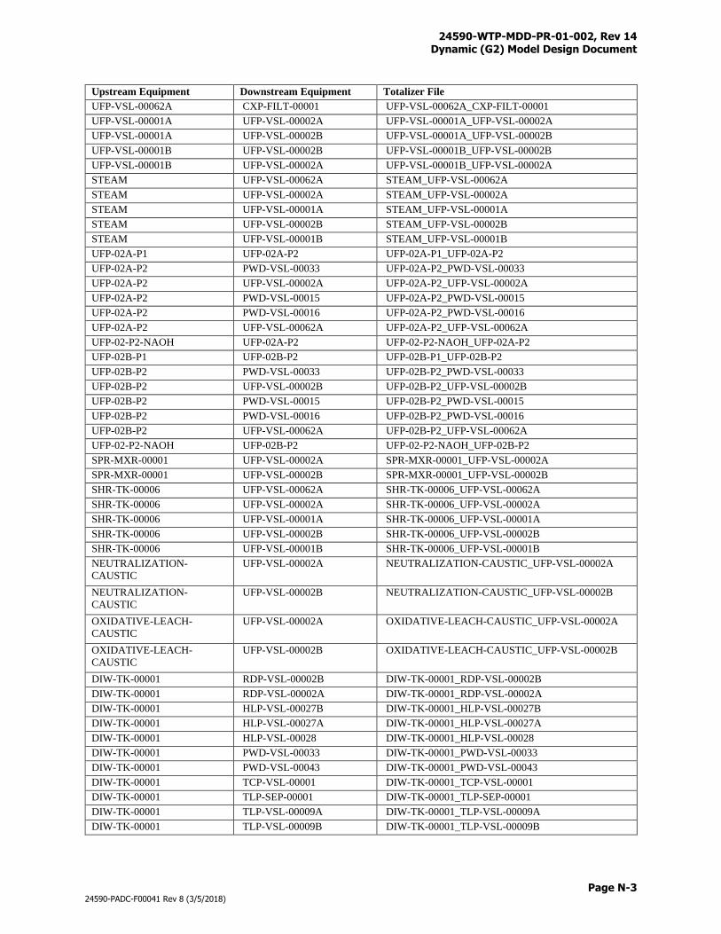
24590-WTP-MDD-PR-01-002, Rev 14 Dynamic (G2) Model Design Document
Page N-3
24590-PADC-F00041 Rev 8 (3/5/2018)
Upstream Equipment Downstream Equipment Totalizer File
UFP-VSL-00062A CXP-FILT-00001 UFP-VSL-00062A_CXP-FILT-00001
UFP-VSL-00001A UFP-VSL-00002A UFP-VSL-00001A_UFP-VSL-00002A
UFP-VSL-00001A UFP-VSL-00002B UFP-VSL-00001A_UFP-VSL-00002B
UFP-VSL-00001B UFP-VSL-00002B UFP-VSL-00001B_UFP-VSL-00002B
UFP-VSL-00001B UFP-VSL-00002A UFP-VSL-00001B_UFP-VSL-00002A
STEAM UFP-VSL-00062A STEAM_UFP-VSL-00062A
STEAM UFP-VSL-00002A STEAM_UFP-VSL-00002A
STEAM UFP-VSL-00001A STEAM_UFP-VSL-00001A
STEAM UFP-VSL-00002B STEAM_UFP-VSL-00002B
STEAM UFP-VSL-00001B STEAM_UFP-VSL-00001B
UFP-02A-P1 UFP-02A-P2 UFP-02A-P1_UFP-02A-P2
UFP-02A-P2 PWD-VSL-00033 UFP-02A-P2_PWD-VSL-00033
UFP-02A-P2 UFP-VSL-00002A UFP-02A-P2_UFP-VSL-00002A
UFP-02A-P2 PWD-VSL-00015 UFP-02A-P2_PWD-VSL-00015
UFP-02A-P2 PWD-VSL-00016 UFP-02A-P2_PWD-VSL-00016
UFP-02A-P2 UFP-VSL-00062A UFP-02A-P2_UFP-VSL-00062A
UFP-02-P2-NAOH UFP-02A-P2 UFP-02-P2-NAOH_UFP-02A-P2
UFP-02B-P1 UFP-02B-P2 UFP-02B-P1_UFP-02B-P2
UFP-02B-P2 PWD-VSL-00033 UFP-02B-P2_PWD-VSL-00033
UFP-02B-P2 UFP-VSL-00002B UFP-02B-P2_UFP-VSL-00002B
UFP-02B-P2 PWD-VSL-00015 UFP-02B-P2_PWD-VSL-00015
UFP-02B-P2 PWD-VSL-00016 UFP-02B-P2_PWD-VSL-00016
UFP-02B-P2 UFP-VSL-00062A UFP-02B-P2_UFP-VSL-00062A
UFP-02-P2-NAOH UFP-02B-P2 UFP-02-P2-NAOH_UFP-02B-P2
SPR-MXR-00001 UFP-VSL-00002A SPR-MXR-00001_UFP-VSL-00002A
SPR-MXR-00001 UFP-VSL-00002B SPR-MXR-00001_UFP-VSL-00002B
SHR-TK-00006 UFP-VSL-00062A SHR-TK-00006_UFP-VSL-00062A
SHR-TK-00006 UFP-VSL-00002A SHR-TK-00006_UFP-VSL-00002A
SHR-TK-00006 UFP-VSL-00001A SHR-TK-00006_UFP-VSL-00001A
SHR-TK-00006 UFP-VSL-00002B SHR-TK-00006_UFP-VSL-00002B
SHR-TK-00006 UFP-VSL-00001B SHR-TK-00006_UFP-VSL-00001B
NEUTRALIZATION-
CAUSTIC
UFP-VSL-00002A NEUTRALIZATION-CAUSTIC_UFP-VSL-00002A
NEUTRALIZATION-
CAUSTIC
UFP-VSL-00002B NEUTRALIZATION-CAUSTIC_UFP-VSL-00002B
OXIDATIVE-LEACH-
CAUSTIC
UFP-VSL-00002A OXIDATIVE-LEACH-CAUSTIC_UFP-VSL-00002A
OXIDATIVE-LEACH-
CAUSTIC
UFP-VSL-00002B OXIDATIVE-LEACH-CAUSTIC_UFP-VSL-00002B
DIW-TK-00001 RDP-VSL-00002B DIW-TK-00001_RDP-VSL-00002B
DIW-TK-00001 RDP-VSL-00002A DIW-TK-00001_RDP-VSL-00002A
DIW-TK-00001 HLP-VSL-00027B DIW-TK-00001_HLP-VSL-00027B
DIW-TK-00001 HLP-VSL-00027A DIW-TK-00001_HLP-VSL-00027A
DIW-TK-00001 HLP-VSL-00028 DIW-TK-00001_HLP-VSL-00028
DIW-TK-00001 PWD-VSL-00033 DIW-TK-00001_PWD-VSL-00033
DIW-TK-00001 PWD-VSL-00043 DIW-TK-00001_PWD-VSL-00043
DIW-TK-00001 TCP-VSL-00001 DIW-TK-00001_TCP-VSL-00001
DIW-TK-00001 TLP-SEP-00001 DIW-TK-00001_TLP-SEP-00001
DIW-TK-00001 TLP-VSL-00009A DIW-TK-00001_TLP-VSL-00009A
DIW-TK-00001 TLP-VSL-00009B DIW-TK-00001_TLP-VSL-00009B
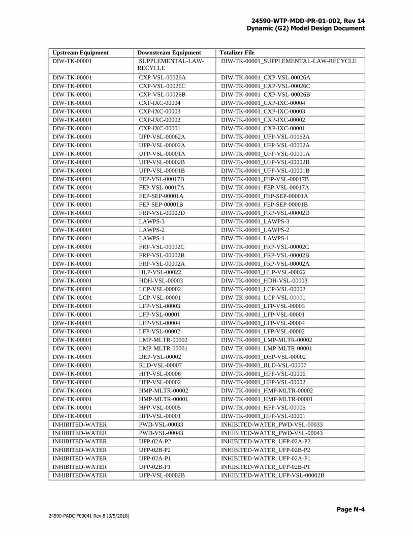
24590-WTP-MDD-PR-01-002, Rev 14 Dynamic (G2) Model Design Document
Page N-4
24590-PADC-F00041 Rev 8 (3/5/2018)
Upstream Equipment Downstream Equipment Totalizer File
DIW-TK-00001 SUPPLEMENTAL-LAW-
RECYCLE
DIW-TK-00001_SUPPLEMENTAL-LAW-RECYCLE
DIW-TK-00001 CXP-VSL-00026A DIW-TK-00001_CXP-VSL-00026A
DIW-TK-00001 CXP-VSL-00026C DIW-TK-00001_CXP-VSL-00026C
DIW-TK-00001 CXP-VSL-00026B DIW-TK-00001_CXP-VSL-00026B
DIW-TK-00001 CXP-IXC-00004 DIW-TK-00001_CXP-IXC-00004
DIW-TK-00001 CXP-IXC-00003 DIW-TK-00001_CXP-IXC-00003
DIW-TK-00001 CXP-IXC-00002 DIW-TK-00001_CXP-IXC-00002
DIW-TK-00001 CXP-IXC-00001 DIW-TK-00001_CXP-IXC-00001
DIW-TK-00001 UFP-VSL-00062A DIW-TK-00001_UFP-VSL-00062A
DIW-TK-00001 UFP-VSL-00002A DIW-TK-00001_UFP-VSL-00002A
DIW-TK-00001 UFP-VSL-00001A DIW-TK-00001_UFP-VSL-00001A
DIW-TK-00001 UFP-VSL-00002B DIW-TK-00001_UFP-VSL-00002B
DIW-TK-00001 UFP-VSL-00001B DIW-TK-00001_UFP-VSL-00001B
DIW-TK-00001 FEP-VSL-00017B DIW-TK-00001_FEP-VSL-00017B
DIW-TK-00001 FEP-VSL-00017A DIW-TK-00001_FEP-VSL-00017A
DIW-TK-00001 FEP-SEP-00001A DIW-TK-00001_FEP-SEP-00001A
DIW-TK-00001 FEP-SEP-00001B DIW-TK-00001_FEP-SEP-00001B
DIW-TK-00001 FRP-VSL-00002D DIW-TK-00001_FRP-VSL-00002D
DIW-TK-00001 LAWPS-3 DIW-TK-00001_LAWPS-3
DIW-TK-00001 LAWPS-2 DIW-TK-00001_LAWPS-2
DIW-TK-00001 LAWPS-1 DIW-TK-00001_LAWPS-1
DIW-TK-00001 FRP-VSL-00002C DIW-TK-00001_FRP-VSL-00002C
DIW-TK-00001 FRP-VSL-00002B DIW-TK-00001_FRP-VSL-00002B
DIW-TK-00001 FRP-VSL-00002A DIW-TK-00001_FRP-VSL-00002A
DIW-TK-00001 HLP-VSL-00022 DIW-TK-00001_HLP-VSL-00022
DIW-TK-00001 HDH-VSL-00003 DIW-TK-00001_HDH-VSL-00003
DIW-TK-00001 LCP-VSL-00002 DIW-TK-00001_LCP-VSL-00002
DIW-TK-00001 LCP-VSL-00001 DIW-TK-00001_LCP-VSL-00001
DIW-TK-00001 LFP-VSL-00003 DIW-TK-00001_LFP-VSL-00003
DIW-TK-00001 LFP-VSL-00001 DIW-TK-00001_LFP-VSL-00001
DIW-TK-00001 LFP-VSL-00004 DIW-TK-00001_LFP-VSL-00004
DIW-TK-00001 LFP-VSL-00002 DIW-TK-00001_LFP-VSL-00002
DIW-TK-00001 LMP-MLTR-00002 DIW-TK-00001_LMP-MLTR-00002
DIW-TK-00001 LMP-MLTR-00001 DIW-TK-00001_LMP-MLTR-00001
DIW-TK-00001 DEP-VSL-00002 DIW-TK-00001_DEP-VSL-00002
DIW-TK-00001 RLD-VSL-00007 DIW-TK-00001_RLD-VSL-00007
DIW-TK-00001 HFP-VSL-00006 DIW-TK-00001_HFP-VSL-00006
DIW-TK-00001 HFP-VSL-00002 DIW-TK-00001_HFP-VSL-00002
DIW-TK-00001 HMP-MLTR-00002 DIW-TK-00001_HMP-MLTR-00002
DIW-TK-00001 HMP-MLTR-00001 DIW-TK-00001_HMP-MLTR-00001
DIW-TK-00001 HFP-VSL-00005 DIW-TK-00001_HFP-VSL-00005
DIW-TK-00001 HFP-VSL-00001 DIW-TK-00001_HFP-VSL-00001
INHIBITED-WATER PWD-VSL-00033 INHIBITED-WATER_PWD-VSL-00033
INHIBITED-WATER PWD-VSL-00043 INHIBITED-WATER_PWD-VSL-00043
INHIBITED-WATER UFP-02A-P2 INHIBITED-WATER_UFP-02A-P2
INHIBITED-WATER UFP-02B-P2 INHIBITED-WATER_UFP-02B-P2
INHIBITED-WATER UFP-02A-P1 INHIBITED-WATER_UFP-02A-P1
INHIBITED-WATER UFP-02B-P1 INHIBITED-WATER_UFP-02B-P1
INHIBITED-WATER UFP-VSL-00002B INHIBITED-WATER_UFP-VSL-00002B
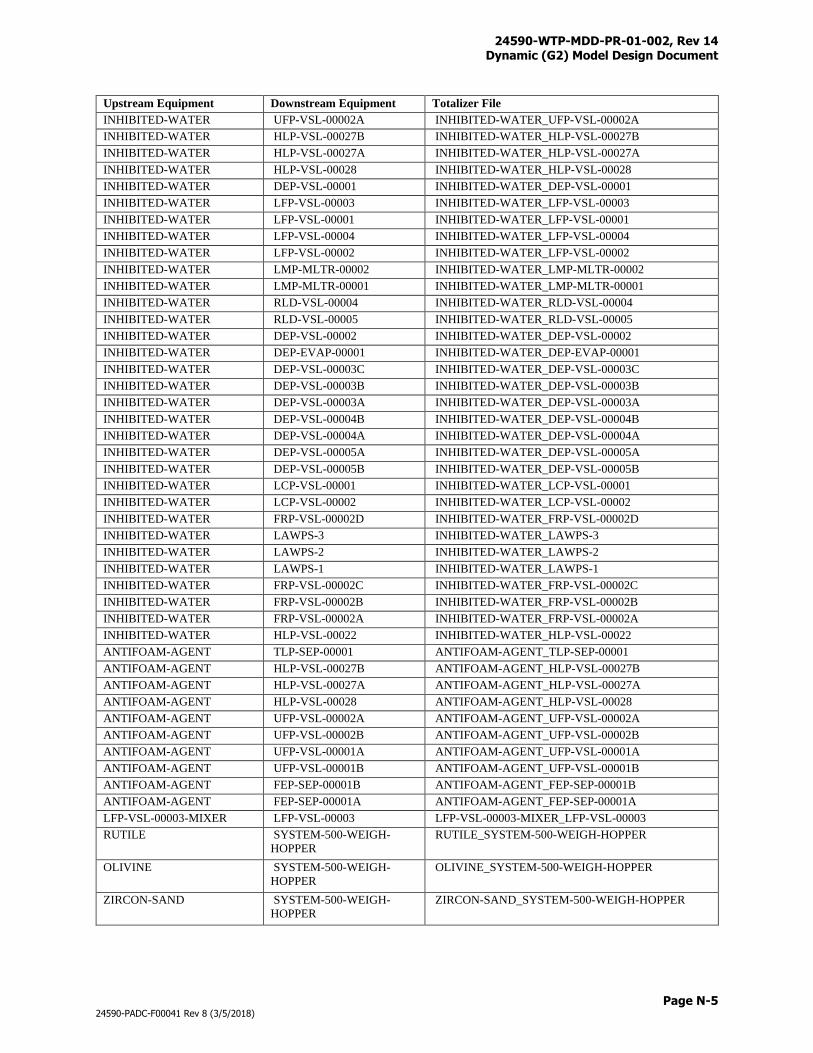
24590-WTP-MDD-PR-01-002, Rev 14 Dynamic (G2) Model Design Document
Page N-5
24590-PADC-F00041 Rev 8 (3/5/2018)
Upstream Equipment Downstream Equipment Totalizer File
INHIBITED-WATER UFP-VSL-00002A INHIBITED-WATER_UFP-VSL-00002A
INHIBITED-WATER HLP-VSL-00027B INHIBITED-WATER_HLP-VSL-00027B
INHIBITED-WATER HLP-VSL-00027A INHIBITED-WATER_HLP-VSL-00027A
INHIBITED-WATER HLP-VSL-00028 INHIBITED-WATER_HLP-VSL-00028
INHIBITED-WATER DEP-VSL-00001 INHIBITED-WATER_DEP-VSL-00001
INHIBITED-WATER LFP-VSL-00003 INHIBITED-WATER_LFP-VSL-00003
INHIBITED-WATER LFP-VSL-00001 INHIBITED-WATER_LFP-VSL-00001
INHIBITED-WATER LFP-VSL-00004 INHIBITED-WATER_LFP-VSL-00004
INHIBITED-WATER LFP-VSL-00002 INHIBITED-WATER_LFP-VSL-00002
INHIBITED-WATER LMP-MLTR-00002 INHIBITED-WATER_LMP-MLTR-00002
INHIBITED-WATER LMP-MLTR-00001 INHIBITED-WATER_LMP-MLTR-00001
INHIBITED-WATER RLD-VSL-00004 INHIBITED-WATER_RLD-VSL-00004
INHIBITED-WATER RLD-VSL-00005 INHIBITED-WATER_RLD-VSL-00005
INHIBITED-WATER DEP-VSL-00002 INHIBITED-WATER_DEP-VSL-00002
INHIBITED-WATER DEP-EVAP-00001 INHIBITED-WATER_DEP-EVAP-00001
INHIBITED-WATER DEP-VSL-00003C INHIBITED-WATER_DEP-VSL-00003C
INHIBITED-WATER DEP-VSL-00003B INHIBITED-WATER_DEP-VSL-00003B
INHIBITED-WATER DEP-VSL-00003A INHIBITED-WATER_DEP-VSL-00003A
INHIBITED-WATER DEP-VSL-00004B INHIBITED-WATER_DEP-VSL-00004B
INHIBITED-WATER DEP-VSL-00004A INHIBITED-WATER_DEP-VSL-00004A
INHIBITED-WATER DEP-VSL-00005A INHIBITED-WATER_DEP-VSL-00005A
INHIBITED-WATER DEP-VSL-00005B INHIBITED-WATER_DEP-VSL-00005B
INHIBITED-WATER LCP-VSL-00001 INHIBITED-WATER_LCP-VSL-00001
INHIBITED-WATER LCP-VSL-00002 INHIBITED-WATER_LCP-VSL-00002
INHIBITED-WATER FRP-VSL-00002D INHIBITED-WATER_FRP-VSL-00002D
INHIBITED-WATER LAWPS-3 INHIBITED-WATER_LAWPS-3
INHIBITED-WATER LAWPS-2 INHIBITED-WATER_LAWPS-2
INHIBITED-WATER LAWPS-1 INHIBITED-WATER_LAWPS-1
INHIBITED-WATER FRP-VSL-00002C INHIBITED-WATER_FRP-VSL-00002C
INHIBITED-WATER FRP-VSL-00002B INHIBITED-WATER_FRP-VSL-00002B
INHIBITED-WATER FRP-VSL-00002A INHIBITED-WATER_FRP-VSL-00002A
INHIBITED-WATER HLP-VSL-00022 INHIBITED-WATER_HLP-VSL-00022
ANTIFOAM-AGENT TLP-SEP-00001 ANTIFOAM-AGENT_TLP-SEP-00001
ANTIFOAM-AGENT HLP-VSL-00027B ANTIFOAM-AGENT_HLP-VSL-00027B
ANTIFOAM-AGENT HLP-VSL-00027A ANTIFOAM-AGENT_HLP-VSL-00027A
ANTIFOAM-AGENT HLP-VSL-00028 ANTIFOAM-AGENT_HLP-VSL-00028
ANTIFOAM-AGENT UFP-VSL-00002A ANTIFOAM-AGENT_UFP-VSL-00002A
ANTIFOAM-AGENT UFP-VSL-00002B ANTIFOAM-AGENT_UFP-VSL-00002B
ANTIFOAM-AGENT UFP-VSL-00001A ANTIFOAM-AGENT_UFP-VSL-00001A
ANTIFOAM-AGENT UFP-VSL-00001B ANTIFOAM-AGENT_UFP-VSL-00001B
ANTIFOAM-AGENT FEP-SEP-00001B ANTIFOAM-AGENT_FEP-SEP-00001B
ANTIFOAM-AGENT FEP-SEP-00001A ANTIFOAM-AGENT_FEP-SEP-00001A
LFP-VSL-00003-MIXER LFP-VSL-00003 LFP-VSL-00003-MIXER_LFP-VSL-00003
RUTILE SYSTEM-500-WEIGH-
HOPPER
RUTILE_SYSTEM-500-WEIGH-HOPPER
OLIVINE SYSTEM-500-WEIGH-
HOPPER
OLIVINE_SYSTEM-500-WEIGH-HOPPER
ZIRCON-SAND SYSTEM-500-WEIGH-
HOPPER
ZIRCON-SAND_SYSTEM-500-WEIGH-HOPPER
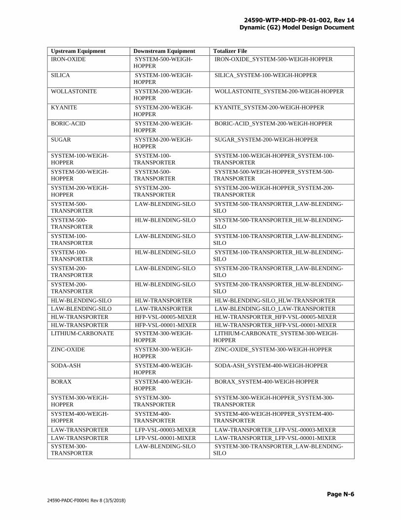
24590-WTP-MDD-PR-01-002, Rev 14 Dynamic (G2) Model Design Document
Page N-6
24590-PADC-F00041 Rev 8 (3/5/2018)
Upstream Equipment Downstream Equipment Totalizer File
IRON-OXIDE SYSTEM-500-WEIGH-
HOPPER
IRON-OXIDE_SYSTEM-500-WEIGH-HOPPER
SILICA SYSTEM-100-WEIGH-
HOPPER
SILICA_SYSTEM-100-WEIGH-HOPPER
WOLLASTONITE SYSTEM-200-WEIGH-
HOPPER
WOLLASTONITE_SYSTEM-200-WEIGH-HOPPER
KYANITE SYSTEM-200-WEIGH-
HOPPER
KYANITE_SYSTEM-200-WEIGH-HOPPER
BORIC-ACID SYSTEM-200-WEIGH-
HOPPER
BORIC-ACID_SYSTEM-200-WEIGH-HOPPER
SUGAR SYSTEM-200-WEIGH-
HOPPER
SUGAR_SYSTEM-200-WEIGH-HOPPER
SYSTEM-100-WEIGH-
HOPPER
SYSTEM-100-
TRANSPORTER
SYSTEM-100-WEIGH-HOPPER_SYSTEM-100-
TRANSPORTER
SYSTEM-500-WEIGH-
HOPPER
SYSTEM-500-
TRANSPORTER
SYSTEM-500-WEIGH-HOPPER_SYSTEM-500-
TRANSPORTER
SYSTEM-200-WEIGH-
HOPPER
SYSTEM-200-
TRANSPORTER
SYSTEM-200-WEIGH-HOPPER_SYSTEM-200-
TRANSPORTER
SYSTEM-500-
TRANSPORTER
LAW-BLENDING-SILO SYSTEM-500-TRANSPORTER_LAW-BLENDING-
SILO
SYSTEM-500-
TRANSPORTER
HLW-BLENDING-SILO SYSTEM-500-TRANSPORTER_HLW-BLENDING-
SILO
SYSTEM-100-
TRANSPORTER
LAW-BLENDING-SILO SYSTEM-100-TRANSPORTER_LAW-BLENDING-
SILO
SYSTEM-100-
TRANSPORTER
HLW-BLENDING-SILO SYSTEM-100-TRANSPORTER_HLW-BLENDING-
SILO
SYSTEM-200-
TRANSPORTER
LAW-BLENDING-SILO SYSTEM-200-TRANSPORTER_LAW-BLENDING-
SILO
SYSTEM-200-
TRANSPORTER
HLW-BLENDING-SILO SYSTEM-200-TRANSPORTER_HLW-BLENDING-
SILO
HLW-BLENDING-SILO HLW-TRANSPORTER HLW-BLENDING-SILO_HLW-TRANSPORTER
LAW-BLENDING-SILO LAW-TRANSPORTER LAW-BLENDING-SILO_LAW-TRANSPORTER
HLW-TRANSPORTER HFP-VSL-00005-MIXER HLW-TRANSPORTER_HFP-VSL-00005-MIXER
HLW-TRANSPORTER HFP-VSL-00001-MIXER HLW-TRANSPORTER_HFP-VSL-00001-MIXER
LITHIUM-CARBONATE SYSTEM-300-WEIGH-
HOPPER
LITHIUM-CARBONATE_SYSTEM-300-WEIGH-
HOPPER
ZINC-OXIDE SYSTEM-300-WEIGH-
HOPPER
ZINC-OXIDE_SYSTEM-300-WEIGH-HOPPER
SODA-ASH SYSTEM-400-WEIGH-
HOPPER
SODA-ASH_SYSTEM-400-WEIGH-HOPPER
BORAX SYSTEM-400-WEIGH-
HOPPER
BORAX_SYSTEM-400-WEIGH-HOPPER
SYSTEM-300-WEIGH-
HOPPER
SYSTEM-300-
TRANSPORTER
SYSTEM-300-WEIGH-HOPPER_SYSTEM-300-
TRANSPORTER
SYSTEM-400-WEIGH-
HOPPER
SYSTEM-400-
TRANSPORTER
SYSTEM-400-WEIGH-HOPPER_SYSTEM-400-
TRANSPORTER
LAW-TRANSPORTER LFP-VSL-00003-MIXER LAW-TRANSPORTER_LFP-VSL-00003-MIXER
LAW-TRANSPORTER LFP-VSL-00001-MIXER LAW-TRANSPORTER_LFP-VSL-00001-MIXER
SYSTEM-300-
TRANSPORTER
LAW-BLENDING-SILO SYSTEM-300-TRANSPORTER_LAW-BLENDING-
SILO
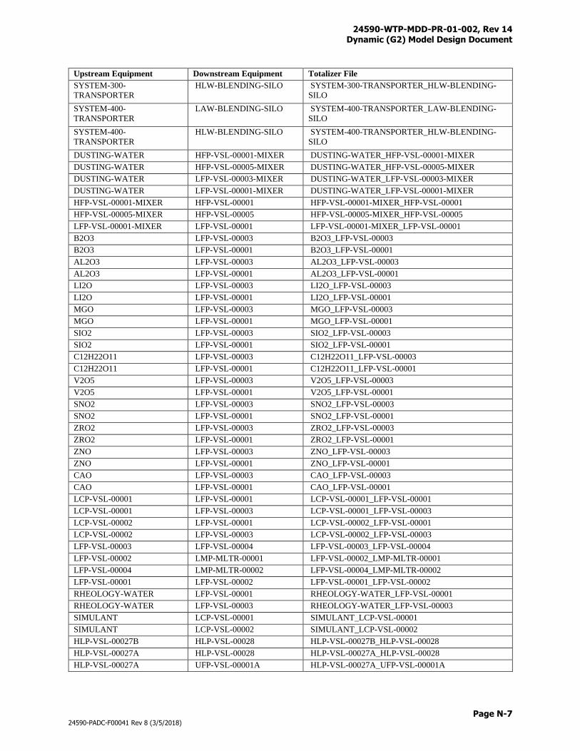
24590-WTP-MDD-PR-01-002, Rev 14 Dynamic (G2) Model Design Document
Page N-7
24590-PADC-F00041 Rev 8 (3/5/2018)
Upstream Equipment Downstream Equipment Totalizer File
SYSTEM-300-
TRANSPORTER
HLW-BLENDING-SILO SYSTEM-300-TRANSPORTER_HLW-BLENDING-
SILO
SYSTEM-400-
TRANSPORTER
LAW-BLENDING-SILO SYSTEM-400-TRANSPORTER_LAW-BLENDING-
SILO
SYSTEM-400-
TRANSPORTER
HLW-BLENDING-SILO SYSTEM-400-TRANSPORTER_HLW-BLENDING-
SILO
DUSTING-WATER HFP-VSL-00001-MIXER DUSTING-WATER_HFP-VSL-00001-MIXER
DUSTING-WATER HFP-VSL-00005-MIXER DUSTING-WATER_HFP-VSL-00005-MIXER
DUSTING-WATER LFP-VSL-00003-MIXER DUSTING-WATER_LFP-VSL-00003-MIXER
DUSTING-WATER LFP-VSL-00001-MIXER DUSTING-WATER_LFP-VSL-00001-MIXER
HFP-VSL-00001-MIXER HFP-VSL-00001 HFP-VSL-00001-MIXER_HFP-VSL-00001
HFP-VSL-00005-MIXER HFP-VSL-00005 HFP-VSL-00005-MIXER_HFP-VSL-00005
LFP-VSL-00001-MIXER LFP-VSL-00001 LFP-VSL-00001-MIXER_LFP-VSL-00001
B2O3 LFP-VSL-00003 B2O3_LFP-VSL-00003
B2O3 LFP-VSL-00001 B2O3_LFP-VSL-00001
AL2O3 LFP-VSL-00003 AL2O3_LFP-VSL-00003
AL2O3 LFP-VSL-00001 AL2O3_LFP-VSL-00001
LI2O LFP-VSL-00003 LI2O_LFP-VSL-00003
LI2O LFP-VSL-00001 LI2O_LFP-VSL-00001
MGO LFP-VSL-00003 MGO_LFP-VSL-00003
MGO LFP-VSL-00001 MGO_LFP-VSL-00001
SIO2 LFP-VSL-00003 SIO2_LFP-VSL-00003
SIO2 LFP-VSL-00001 SIO2_LFP-VSL-00001
C12H22O11 LFP-VSL-00003 C12H22O11_LFP-VSL-00003
C12H22O11 LFP-VSL-00001 C12H22O11_LFP-VSL-00001
V2O5 LFP-VSL-00003 V2O5_LFP-VSL-00003
V2O5 LFP-VSL-00001 V2O5_LFP-VSL-00001
SNO2 LFP-VSL-00003 SNO2_LFP-VSL-00003
SNO2 LFP-VSL-00001 SNO2_LFP-VSL-00001
ZRO2 LFP-VSL-00003 ZRO2_LFP-VSL-00003
ZRO2 LFP-VSL-00001 ZRO2_LFP-VSL-00001
ZNO LFP-VSL-00003 ZNO_LFP-VSL-00003
ZNO LFP-VSL-00001 ZNO_LFP-VSL-00001
CAO LFP-VSL-00003 CAO_LFP-VSL-00003
CAO LFP-VSL-00001 CAO_LFP-VSL-00001
LCP-VSL-00001 LFP-VSL-00001 LCP-VSL-00001_LFP-VSL-00001
LCP-VSL-00001 LFP-VSL-00003 LCP-VSL-00001_LFP-VSL-00003
LCP-VSL-00002 LFP-VSL-00001 LCP-VSL-00002_LFP-VSL-00001
LCP-VSL-00002 LFP-VSL-00003 LCP-VSL-00002_LFP-VSL-00003
LFP-VSL-00003 LFP-VSL-00004 LFP-VSL-00003_LFP-VSL-00004
LFP-VSL-00002 LMP-MLTR-00001 LFP-VSL-00002_LMP-MLTR-00001
LFP-VSL-00004 LMP-MLTR-00002 LFP-VSL-00004_LMP-MLTR-00002
LFP-VSL-00001 LFP-VSL-00002 LFP-VSL-00001_LFP-VSL-00002
RHEOLOGY-WATER LFP-VSL-00001 RHEOLOGY-WATER_LFP-VSL-00001
RHEOLOGY-WATER LFP-VSL-00003 RHEOLOGY-WATER_LFP-VSL-00003
SIMULANT LCP-VSL-00001 SIMULANT_LCP-VSL-00001
SIMULANT LCP-VSL-00002 SIMULANT_LCP-VSL-00002
HLP-VSL-00027B HLP-VSL-00028 HLP-VSL-00027B_HLP-VSL-00028
HLP-VSL-00027A HLP-VSL-00028 HLP-VSL-00027A_HLP-VSL-00028
HLP-VSL-00027A UFP-VSL-00001A HLP-VSL-00027A_UFP-VSL-00001A
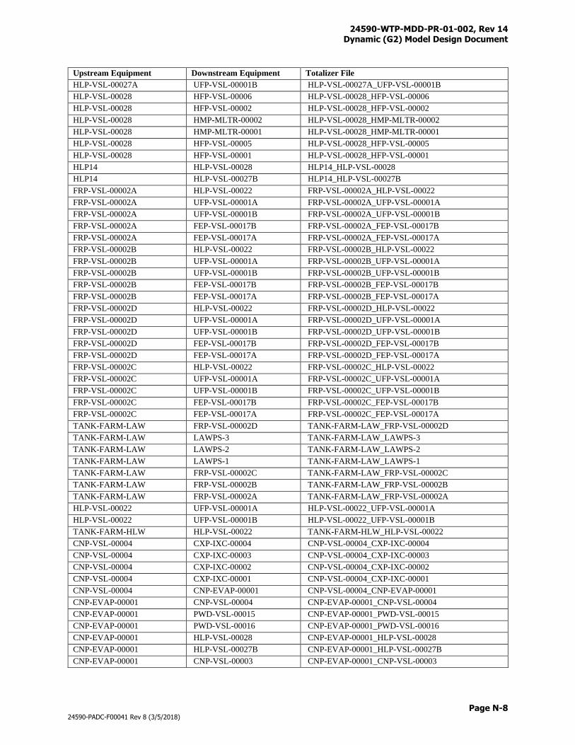
24590-WTP-MDD-PR-01-002, Rev 14 Dynamic (G2) Model Design Document
Page N-8
24590-PADC-F00041 Rev 8 (3/5/2018)
Upstream Equipment Downstream Equipment Totalizer File
HLP-VSL-00027A UFP-VSL-00001B HLP-VSL-00027A_UFP-VSL-00001B
HLP-VSL-00028 HFP-VSL-00006 HLP-VSL-00028_HFP-VSL-00006
HLP-VSL-00028 HFP-VSL-00002 HLP-VSL-00028_HFP-VSL-00002
HLP-VSL-00028 HMP-MLTR-00002 HLP-VSL-00028_HMP-MLTR-00002
HLP-VSL-00028 HMP-MLTR-00001 HLP-VSL-00028_HMP-MLTR-00001
HLP-VSL-00028 HFP-VSL-00005 HLP-VSL-00028_HFP-VSL-00005
HLP-VSL-00028 HFP-VSL-00001 HLP-VSL-00028_HFP-VSL-00001
HLP14 HLP-VSL-00028 HLP14_HLP-VSL-00028
HLP14 HLP-VSL-00027B HLP14_HLP-VSL-00027B
FRP-VSL-00002A HLP-VSL-00022 FRP-VSL-00002A_HLP-VSL-00022
FRP-VSL-00002A UFP-VSL-00001A FRP-VSL-00002A_UFP-VSL-00001A
FRP-VSL-00002A UFP-VSL-00001B FRP-VSL-00002A_UFP-VSL-00001B
FRP-VSL-00002A FEP-VSL-00017B FRP-VSL-00002A_FEP-VSL-00017B
FRP-VSL-00002A FEP-VSL-00017A FRP-VSL-00002A_FEP-VSL-00017A
FRP-VSL-00002B HLP-VSL-00022 FRP-VSL-00002B_HLP-VSL-00022
FRP-VSL-00002B UFP-VSL-00001A FRP-VSL-00002B_UFP-VSL-00001A
FRP-VSL-00002B UFP-VSL-00001B FRP-VSL-00002B_UFP-VSL-00001B
FRP-VSL-00002B FEP-VSL-00017B FRP-VSL-00002B_FEP-VSL-00017B
FRP-VSL-00002B FEP-VSL-00017A FRP-VSL-00002B_FEP-VSL-00017A
FRP-VSL-00002D HLP-VSL-00022 FRP-VSL-00002D_HLP-VSL-00022
FRP-VSL-00002D UFP-VSL-00001A FRP-VSL-00002D_UFP-VSL-00001A
FRP-VSL-00002D UFP-VSL-00001B FRP-VSL-00002D_UFP-VSL-00001B
FRP-VSL-00002D FEP-VSL-00017B FRP-VSL-00002D_FEP-VSL-00017B
FRP-VSL-00002D FEP-VSL-00017A FRP-VSL-00002D_FEP-VSL-00017A
FRP-VSL-00002C HLP-VSL-00022 FRP-VSL-00002C_HLP-VSL-00022
FRP-VSL-00002C UFP-VSL-00001A FRP-VSL-00002C_UFP-VSL-00001A
FRP-VSL-00002C UFP-VSL-00001B FRP-VSL-00002C_UFP-VSL-00001B
FRP-VSL-00002C FEP-VSL-00017B FRP-VSL-00002C_FEP-VSL-00017B
FRP-VSL-00002C FEP-VSL-00017A FRP-VSL-00002C_FEP-VSL-00017A
TANK-FARM-LAW FRP-VSL-00002D TANK-FARM-LAW_FRP-VSL-00002D
TANK-FARM-LAW LAWPS-3 TANK-FARM-LAW_LAWPS-3
TANK-FARM-LAW LAWPS-2 TANK-FARM-LAW_LAWPS-2
TANK-FARM-LAW LAWPS-1 TANK-FARM-LAW_LAWPS-1
TANK-FARM-LAW FRP-VSL-00002C TANK-FARM-LAW_FRP-VSL-00002C
TANK-FARM-LAW FRP-VSL-00002B TANK-FARM-LAW_FRP-VSL-00002B
TANK-FARM-LAW FRP-VSL-00002A TANK-FARM-LAW_FRP-VSL-00002A
HLP-VSL-00022 UFP-VSL-00001A HLP-VSL-00022_UFP-VSL-00001A
HLP-VSL-00022 UFP-VSL-00001B HLP-VSL-00022_UFP-VSL-00001B
TANK-FARM-HLW HLP-VSL-00022 TANK-FARM-HLW_HLP-VSL-00022
CNP-VSL-00004 CXP-IXC-00004 CNP-VSL-00004_CXP-IXC-00004
CNP-VSL-00004 CXP-IXC-00003 CNP-VSL-00004_CXP-IXC-00003
CNP-VSL-00004 CXP-IXC-00002 CNP-VSL-00004_CXP-IXC-00002
CNP-VSL-00004 CXP-IXC-00001 CNP-VSL-00004_CXP-IXC-00001
CNP-VSL-00004 CNP-EVAP-00001 CNP-VSL-00004_CNP-EVAP-00001
CNP-EVAP-00001 CNP-VSL-00004 CNP-EVAP-00001_CNP-VSL-00004
CNP-EVAP-00001 PWD-VSL-00015 CNP-EVAP-00001_PWD-VSL-00015
CNP-EVAP-00001 PWD-VSL-00016 CNP-EVAP-00001_PWD-VSL-00016
CNP-EVAP-00001 HLP-VSL-00028 CNP-EVAP-00001_HLP-VSL-00028
CNP-EVAP-00001 HLP-VSL-00027B CNP-EVAP-00001_HLP-VSL-00027B
CNP-EVAP-00001 CNP-VSL-00003 CNP-EVAP-00001_CNP-VSL-00003

24590-WTP-MDD-PR-01-002, Rev 14 Dynamic (G2) Model Design Document
Page N-9
24590-PADC-F00041 Rev 8 (3/5/2018)
Upstream Equipment Downstream Equipment Totalizer File
NAR-TK-00006 CNP-VSL-00004 NAR-TK-00006_CNP-VSL-00004
CNP-VSL-00003 HLP-VSL-00028 CNP-VSL-00003_HLP-VSL-00028
CNP-VSL-00003 HLP-VSL-00027B CNP-VSL-00003_HLP-VSL-00027B
NAR-TK-00005 CNP-EVAP-00001 NAR-TK-00005_CNP-EVAP-00001
PWD-VSL-00015 FEP-VSL-00017B PWD-VSL-00015_FEP-VSL-00017B
PWD-VSL-00015 FEP-VSL-00017A PWD-VSL-00015_FEP-VSL-00017A
PWD-VSL-00016 FEP-VSL-00017B PWD-VSL-00016_FEP-VSL-00017B
PWD-VSL-00016 FEP-VSL-00017A PWD-VSL-00016_FEP-VSL-00017A
PWD-VSL-00044 PWD-VSL-00016 PWD-VSL-00044_PWD-VSL-00016
PWD-VSL-00044 FEP-VSL-00017B PWD-VSL-00044_FEP-VSL-00017B
PWD-VSL-00044 FEP-VSL-00017A PWD-VSL-00044_FEP-VSL-00017A
PWD-VSL-00043 PWD-VSL-00044 PWD-VSL-00043_PWD-VSL-00044
PWD-VSL-00033 PWD-VSL-00044 PWD-VSL-00033_PWD-VSL-00044
SHR-TK-00006 PWD-VSL-00015 SHR-TK-00006_PWD-VSL-00015
SHR-TK-00006 PWD-VSL-00016 SHR-TK-00006_PWD-VSL-00016
SHR-TK-00006 PWD-VSL-00044 SHR-TK-00006_PWD-VSL-00044
RLD-VSL-00008 PWD-VSL-00043 RLD-VSL-00008_PWD-VSL-00043
RLD-VSL-00007 PWD-VSL-00043 RLD-VSL-00007_PWD-VSL-00043
RLD-VSL-00007 RLD-VSL-00008 RLD-VSL-00007_RLD-VSL-00008
RLD-VSL-00007 PJV-HEPA-00004-5 RLD-VSL-00007_PJV-HEPA-00004-5
SHR-TK-00002 RLD-VSL-00007 SHR-TK-00002_RLD-VSL-00007
DIW-IXC-RINSE-1 CXP-IXC-00002 DIW-IXC-RINSE-1_CXP-IXC-00002
DIW-IXC-RINSE-2 CXP-IXC-00002 DIW-IXC-RINSE-2_CXP-IXC-00002
SHR-TK-00005 CXP-IXC-00002 SHR-TK-00005_CXP-IXC-00002
CXP-IXC-00002 CNP-EVAP-00001 CXP-IXC-00002_CNP-EVAP-00001
CXP-IXC-00002 RDP-VSL-00002A CXP-IXC-00002_RDP-VSL-00002A
CXP-IXC-00002 RDP-VSL-00002B CXP-IXC-00002_RDP-VSL-00002B
CXP-IXC-00002 UFP-VSL-00062A CXP-IXC-00002_UFP-VSL-00062A
CXP-IXC-00002 CXP-VSL-00026A CXP-IXC-00002_CXP-VSL-00026A
CXP-IXC-00002 CXP-VSL-00026C CXP-IXC-00002_CXP-VSL-00026C
CXP-IXC-00002 CXP-VSL-00026B CXP-IXC-00002_CXP-VSL-00026B
CXP-IXC-00002 CXP-IXC-00003 CXP-IXC-00002_CXP-IXC-00003
CXP-IXC-00002 PWD-VSL-00015 CXP-IXC-00002_PWD-VSL-00015
CXP-IXC-00002 PWD-VSL-00016 CXP-IXC-00002_PWD-VSL-00016
CXP-IXC-00002 CXP-IXC-00002 CXP-IXC-00002_CXP-IXC-00002
DIW-IXC-RINSE-1 CXP-IXC-00001 DIW-IXC-RINSE-1_CXP-IXC-00001
DIW-IXC-RINSE-2 CXP-IXC-00001 DIW-IXC-RINSE-2_CXP-IXC-00001
SHR-TK-00005 CXP-IXC-00001 SHR-TK-00005_CXP-IXC-00001
CXP-IXC-00001 CNP-EVAP-00001 CXP-IXC-00001_CNP-EVAP-00001
CXP-IXC-00001 RDP-VSL-00002A CXP-IXC-00001_RDP-VSL-00002A
CXP-IXC-00001 RDP-VSL-00002B CXP-IXC-00001_RDP-VSL-00002B
CXP-IXC-00001 UFP-VSL-00062A CXP-IXC-00001_UFP-VSL-00062A
CXP-IXC-00001 CXP-VSL-00026A CXP-IXC-00001_CXP-VSL-00026A
CXP-IXC-00001 CXP-VSL-00026C CXP-IXC-00001_CXP-VSL-00026C
CXP-IXC-00001 CXP-VSL-00026B CXP-IXC-00001_CXP-VSL-00026B
CXP-IXC-00001 CXP-IXC-00002 CXP-IXC-00001_CXP-IXC-00002
CXP-IXC-00001 PWD-VSL-00015 CXP-IXC-00001_PWD-VSL-00015
CXP-IXC-00001 PWD-VSL-00016 CXP-IXC-00001_PWD-VSL-00016
CXP-IXC-00001 CXP-IXC-00001 CXP-IXC-00001_CXP-IXC-00001
DIW-IXC-RINSE-1 CXP-IXC-00004 DIW-IXC-RINSE-1_CXP-IXC-00004
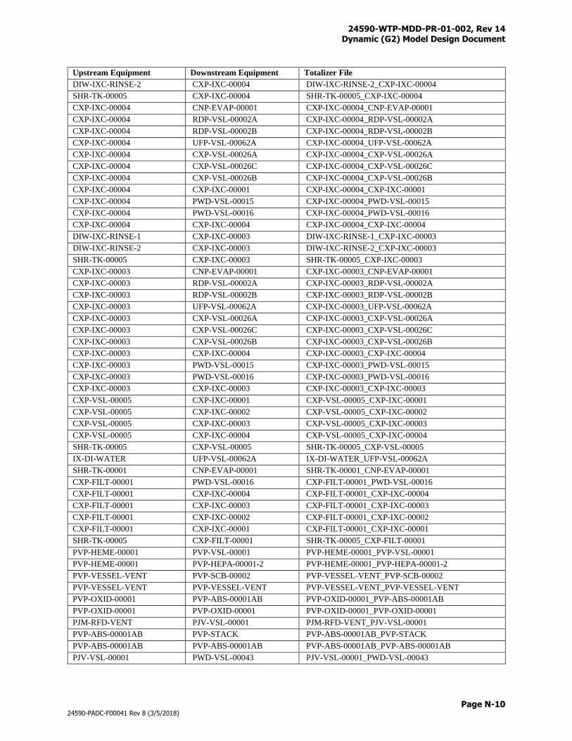
24590-WTP-MDD-PR-01-002, Rev 14 Dynamic (G2) Model Design Document
Page N-10
24590-PADC-F00041 Rev 8 (3/5/2018)
Upstream Equipment Downstream Equipment Totalizer File
DIW-IXC-RINSE-2 CXP-IXC-00004 DIW-IXC-RINSE-2_CXP-IXC-00004
SHR-TK-00005 CXP-IXC-00004 SHR-TK-00005_CXP-IXC-00004
CXP-IXC-00004 CNP-EVAP-00001 CXP-IXC-00004_CNP-EVAP-00001
CXP-IXC-00004 RDP-VSL-00002A CXP-IXC-00004_RDP-VSL-00002A
CXP-IXC-00004 RDP-VSL-00002B CXP-IXC-00004_RDP-VSL-00002B
CXP-IXC-00004 UFP-VSL-00062A CXP-IXC-00004_UFP-VSL-00062A
CXP-IXC-00004 CXP-VSL-00026A CXP-IXC-00004_CXP-VSL-00026A
CXP-IXC-00004 CXP-VSL-00026C CXP-IXC-00004_CXP-VSL-00026C
CXP-IXC-00004 CXP-VSL-00026B CXP-IXC-00004_CXP-VSL-00026B
CXP-IXC-00004 CXP-IXC-00001 CXP-IXC-00004_CXP-IXC-00001
CXP-IXC-00004 PWD-VSL-00015 CXP-IXC-00004_PWD-VSL-00015
CXP-IXC-00004 PWD-VSL-00016 CXP-IXC-00004_PWD-VSL-00016
CXP-IXC-00004 CXP-IXC-00004 CXP-IXC-00004_CXP-IXC-00004
DIW-IXC-RINSE-1 CXP-IXC-00003 DIW-IXC-RINSE-1_CXP-IXC-00003
DIW-IXC-RINSE-2 CXP-IXC-00003 DIW-IXC-RINSE-2_CXP-IXC-00003
SHR-TK-00005 CXP-IXC-00003 SHR-TK-00005_CXP-IXC-00003
CXP-IXC-00003 CNP-EVAP-00001 CXP-IXC-00003_CNP-EVAP-00001
CXP-IXC-00003 RDP-VSL-00002A CXP-IXC-00003_RDP-VSL-00002A
CXP-IXC-00003 RDP-VSL-00002B CXP-IXC-00003_RDP-VSL-00002B
CXP-IXC-00003 UFP-VSL-00062A CXP-IXC-00003_UFP-VSL-00062A
CXP-IXC-00003 CXP-VSL-00026A CXP-IXC-00003_CXP-VSL-00026A
CXP-IXC-00003 CXP-VSL-00026C CXP-IXC-00003_CXP-VSL-00026C
CXP-IXC-00003 CXP-VSL-00026B CXP-IXC-00003_CXP-VSL-00026B
CXP-IXC-00003 CXP-IXC-00004 CXP-IXC-00003_CXP-IXC-00004
CXP-IXC-00003 PWD-VSL-00015 CXP-IXC-00003_PWD-VSL-00015
CXP-IXC-00003 PWD-VSL-00016 CXP-IXC-00003_PWD-VSL-00016
CXP-IXC-00003 CXP-IXC-00003 CXP-IXC-00003_CXP-IXC-00003
CXP-VSL-00005 CXP-IXC-00001 CXP-VSL-00005_CXP-IXC-00001
CXP-VSL-00005 CXP-IXC-00002 CXP-VSL-00005_CXP-IXC-00002
CXP-VSL-00005 CXP-IXC-00003 CXP-VSL-00005_CXP-IXC-00003
CXP-VSL-00005 CXP-IXC-00004 CXP-VSL-00005_CXP-IXC-00004
SHR-TK-00005 CXP-VSL-00005 SHR-TK-00005_CXP-VSL-00005
IX-DI-WATER UFP-VSL-00062A IX-DI-WATER_UFP-VSL-00062A
SHR-TK-00001 CNP-EVAP-00001 SHR-TK-00001_CNP-EVAP-00001
CXP-FILT-00001 PWD-VSL-00016 CXP-FILT-00001_PWD-VSL-00016
CXP-FILT-00001 CXP-IXC-00004 CXP-FILT-00001_CXP-IXC-00004
CXP-FILT-00001 CXP-IXC-00003 CXP-FILT-00001_CXP-IXC-00003
CXP-FILT-00001 CXP-IXC-00002 CXP-FILT-00001_CXP-IXC-00002
CXP-FILT-00001 CXP-IXC-00001 CXP-FILT-00001_CXP-IXC-00001
SHR-TK-00005 CXP-FILT-00001 SHR-TK-00005_CXP-FILT-00001
PVP-HEME-00001 PVP-VSL-00001 PVP-HEME-00001_PVP-VSL-00001
PVP-HEME-00001 PVP-HEPA-00001-2 PVP-HEME-00001_PVP-HEPA-00001-2
PVP-VESSEL-VENT PVP-SCB-00002 PVP-VESSEL-VENT_PVP-SCB-00002
PVP-VESSEL-VENT PVP-VESSEL-VENT PVP-VESSEL-VENT_PVP-VESSEL-VENT
PVP-OXID-00001 PVP-ABS-00001AB PVP-OXID-00001_PVP-ABS-00001AB
PVP-OXID-00001 PVP-OXID-00001 PVP-OXID-00001_PVP-OXID-00001
PJM-RFD-VENT PJV-VSL-00001 PJM-RFD-VENT_PJV-VSL-00001
PVP-ABS-00001AB PVP-STACK PVP-ABS-00001AB_PVP-STACK
PVP-ABS-00001AB PVP-ABS-00001AB PVP-ABS-00001AB_PVP-ABS-00001AB
PJV-VSL-00001 PWD-VSL-00043 PJV-VSL-00001_PWD-VSL-00043
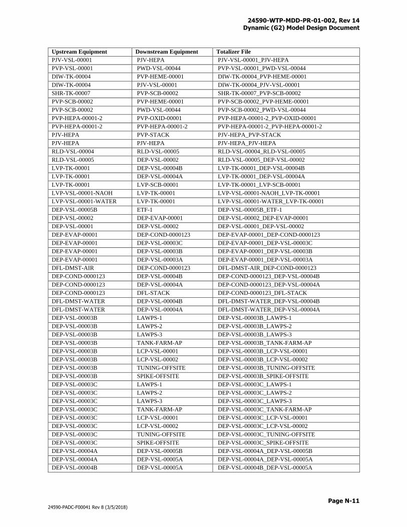
24590-WTP-MDD-PR-01-002, Rev 14 Dynamic (G2) Model Design Document
Page N-11
24590-PADC-F00041 Rev 8 (3/5/2018)
Upstream Equipment Downstream Equipment Totalizer File
PJV-VSL-00001 PJV-HEPA PJV-VSL-00001_PJV-HEPA
PVP-VSL-00001 PWD-VSL-00044 PVP-VSL-00001_PWD-VSL-00044
DIW-TK-00004 PVP-HEME-00001 DIW-TK-00004_PVP-HEME-00001
DIW-TK-00004 PJV-VSL-00001 DIW-TK-00004_PJV-VSL-00001
SHR-TK-00007 PVP-SCB-00002 SHR-TK-00007_PVP-SCB-00002
PVP-SCB-00002 PVP-HEME-00001 PVP-SCB-00002_PVP-HEME-00001
PVP-SCB-00002 PWD-VSL-00044 PVP-SCB-00002_PWD-VSL-00044
PVP-HEPA-00001-2 PVP-OXID-00001 PVP-HEPA-00001-2_PVP-OXID-00001
PVP-HEPA-00001-2 PVP-HEPA-00001-2 PVP-HEPA-00001-2_PVP-HEPA-00001-2
PJV-HEPA PVP-STACK PJV-HEPA_PVP-STACK
PJV-HEPA PJV-HEPA PJV-HEPA_PJV-HEPA
RLD-VSL-00004 RLD-VSL-00005 RLD-VSL-00004_RLD-VSL-00005
RLD-VSL-00005 DEP-VSL-00002 RLD-VSL-00005_DEP-VSL-00002
LVP-TK-00001 DEP-VSL-00004B LVP-TK-00001_DEP-VSL-00004B
LVP-TK-00001 DEP-VSL-00004A LVP-TK-00001_DEP-VSL-00004A
LVP-TK-00001 LVP-SCB-00001 LVP-TK-00001_LVP-SCB-00001
LVP-VSL-00001-NAOH LVP-TK-00001 LVP-VSL-00001-NAOH_LVP-TK-00001
LVP-VSL-00001-WATER LVP-TK-00001 LVP-VSL-00001-WATER_LVP-TK-00001
DEP-VSL-00005B ETF-1 DEP-VSL-00005B_ETF-1
DEP-VSL-00002 DEP-EVAP-00001 DEP-VSL-00002_DEP-EVAP-00001
DEP-VSL-00001 DEP-VSL-00002 DEP-VSL-00001_DEP-VSL-00002
DEP-EVAP-00001 DEP-COND-0000123 DEP-EVAP-00001_DEP-COND-0000123
DEP-EVAP-00001 DEP-VSL-00003C DEP-EVAP-00001_DEP-VSL-00003C
DEP-EVAP-00001 DEP-VSL-00003B DEP-EVAP-00001_DEP-VSL-00003B
DEP-EVAP-00001 DEP-VSL-00003A DEP-EVAP-00001_DEP-VSL-00003A
DFL-DMST-AIR DEP-COND-0000123 DFL-DMST-AIR_DEP-COND-0000123
DEP-COND-0000123 DEP-VSL-00004B DEP-COND-0000123_DEP-VSL-00004B
DEP-COND-0000123 DEP-VSL-00004A DEP-COND-0000123_DEP-VSL-00004A
DEP-COND-0000123 DFL-STACK DEP-COND-0000123_DFL-STACK
DFL-DMST-WATER DEP-VSL-00004B DFL-DMST-WATER_DEP-VSL-00004B
DFL-DMST-WATER DEP-VSL-00004A DFL-DMST-WATER_DEP-VSL-00004A
DEP-VSL-00003B LAWPS-1 DEP-VSL-00003B_LAWPS-1
DEP-VSL-00003B LAWPS-2 DEP-VSL-00003B_LAWPS-2
DEP-VSL-00003B LAWPS-3 DEP-VSL-00003B_LAWPS-3
DEP-VSL-00003B TANK-FARM-AP DEP-VSL-00003B_TANK-FARM-AP
DEP-VSL-00003B LCP-VSL-00001 DEP-VSL-00003B_LCP-VSL-00001
DEP-VSL-00003B LCP-VSL-00002 DEP-VSL-00003B_LCP-VSL-00002
DEP-VSL-00003B TUNING-OFFSITE DEP-VSL-00003B_TUNING-OFFSITE
DEP-VSL-00003B SPIKE-OFFSITE DEP-VSL-00003B_SPIKE-OFFSITE
DEP-VSL-00003C LAWPS-1 DEP-VSL-00003C_LAWPS-1
DEP-VSL-00003C LAWPS-2 DEP-VSL-00003C_LAWPS-2
DEP-VSL-00003C LAWPS-3 DEP-VSL-00003C_LAWPS-3
DEP-VSL-00003C TANK-FARM-AP DEP-VSL-00003C_TANK-FARM-AP
DEP-VSL-00003C LCP-VSL-00001 DEP-VSL-00003C_LCP-VSL-00001
DEP-VSL-00003C LCP-VSL-00002 DEP-VSL-00003C_LCP-VSL-00002
DEP-VSL-00003C TUNING-OFFSITE DEP-VSL-00003C_TUNING-OFFSITE
DEP-VSL-00003C SPIKE-OFFSITE DEP-VSL-00003C_SPIKE-OFFSITE
DEP-VSL-00004A DEP-VSL-00005B DEP-VSL-00004A_DEP-VSL-00005B
DEP-VSL-00004A DEP-VSL-00005A DEP-VSL-00004A_DEP-VSL-00005A
DEP-VSL-00004B DEP-VSL-00005A DEP-VSL-00004B_DEP-VSL-00005A
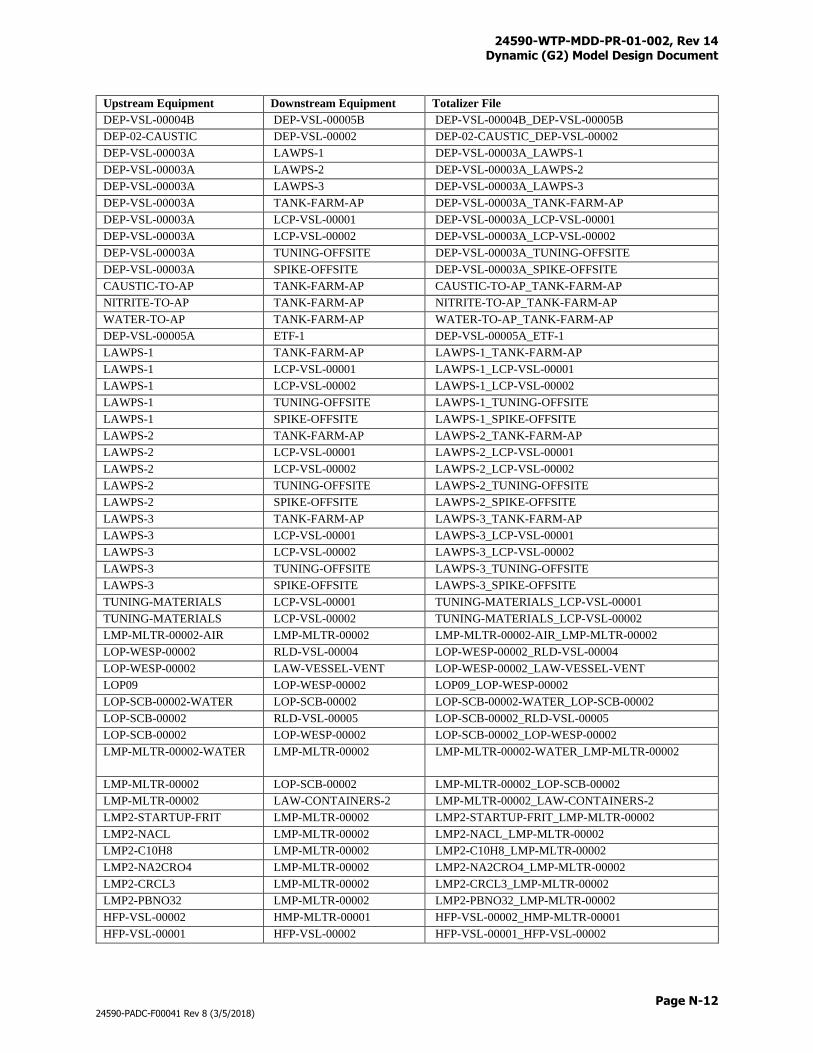
24590-WTP-MDD-PR-01-002, Rev 14 Dynamic (G2) Model Design Document
Page N-12
24590-PADC-F00041 Rev 8 (3/5/2018)
Upstream Equipment Downstream Equipment Totalizer File
DEP-VSL-00004B DEP-VSL-00005B DEP-VSL-00004B_DEP-VSL-00005B
DEP-02-CAUSTIC DEP-VSL-00002 DEP-02-CAUSTIC_DEP-VSL-00002
DEP-VSL-00003A LAWPS-1 DEP-VSL-00003A_LAWPS-1
DEP-VSL-00003A LAWPS-2 DEP-VSL-00003A_LAWPS-2
DEP-VSL-00003A LAWPS-3 DEP-VSL-00003A_LAWPS-3
DEP-VSL-00003A TANK-FARM-AP DEP-VSL-00003A_TANK-FARM-AP
DEP-VSL-00003A LCP-VSL-00001 DEP-VSL-00003A_LCP-VSL-00001
DEP-VSL-00003A LCP-VSL-00002 DEP-VSL-00003A_LCP-VSL-00002
DEP-VSL-00003A TUNING-OFFSITE DEP-VSL-00003A_TUNING-OFFSITE
DEP-VSL-00003A SPIKE-OFFSITE DEP-VSL-00003A_SPIKE-OFFSITE
CAUSTIC-TO-AP TANK-FARM-AP CAUSTIC-TO-AP_TANK-FARM-AP
NITRITE-TO-AP TANK-FARM-AP NITRITE-TO-AP_TANK-FARM-AP
WATER-TO-AP TANK-FARM-AP WATER-TO-AP_TANK-FARM-AP
DEP-VSL-00005A ETF-1 DEP-VSL-00005A_ETF-1
LAWPS-1 TANK-FARM-AP LAWPS-1_TANK-FARM-AP
LAWPS-1 LCP-VSL-00001 LAWPS-1_LCP-VSL-00001
LAWPS-1 LCP-VSL-00002 LAWPS-1_LCP-VSL-00002
LAWPS-1 TUNING-OFFSITE LAWPS-1_TUNING-OFFSITE
LAWPS-1 SPIKE-OFFSITE LAWPS-1_SPIKE-OFFSITE
LAWPS-2 TANK-FARM-AP LAWPS-2_TANK-FARM-AP
LAWPS-2 LCP-VSL-00001 LAWPS-2_LCP-VSL-00001
LAWPS-2 LCP-VSL-00002 LAWPS-2_LCP-VSL-00002
LAWPS-2 TUNING-OFFSITE LAWPS-2_TUNING-OFFSITE
LAWPS-2 SPIKE-OFFSITE LAWPS-2_SPIKE-OFFSITE
LAWPS-3 TANK-FARM-AP LAWPS-3_TANK-FARM-AP
LAWPS-3 LCP-VSL-00001 LAWPS-3_LCP-VSL-00001
LAWPS-3 LCP-VSL-00002 LAWPS-3_LCP-VSL-00002
LAWPS-3 TUNING-OFFSITE LAWPS-3_TUNING-OFFSITE
LAWPS-3 SPIKE-OFFSITE LAWPS-3_SPIKE-OFFSITE
TUNING-MATERIALS LCP-VSL-00001 TUNING-MATERIALS_LCP-VSL-00001
TUNING-MATERIALS LCP-VSL-00002 TUNING-MATERIALS_LCP-VSL-00002
LMP-MLTR-00002-AIR LMP-MLTR-00002 LMP-MLTR-00002-AIR_LMP-MLTR-00002
LOP-WESP-00002 RLD-VSL-00004 LOP-WESP-00002_RLD-VSL-00004
LOP-WESP-00002 LAW-VESSEL-VENT LOP-WESP-00002_LAW-VESSEL-VENT
LOP09 LOP-WESP-00002 LOP09_LOP-WESP-00002
LOP-SCB-00002-WATER LOP-SCB-00002 LOP-SCB-00002-WATER_LOP-SCB-00002
LOP-SCB-00002 RLD-VSL-00005 LOP-SCB-00002_RLD-VSL-00005
LOP-SCB-00002 LOP-WESP-00002 LOP-SCB-00002_LOP-WESP-00002
LMP-MLTR-00002-WATER LMP-MLTR-00002 LMP-MLTR-00002-WATER_LMP-MLTR-00002
LMP-MLTR-00002 LOP-SCB-00002 LMP-MLTR-00002_LOP-SCB-00002
LMP-MLTR-00002 LAW-CONTAINERS-2 LMP-MLTR-00002_LAW-CONTAINERS-2
LMP2-STARTUP-FRIT LMP-MLTR-00002 LMP2-STARTUP-FRIT_LMP-MLTR-00002
LMP2-NACL LMP-MLTR-00002 LMP2-NACL_LMP-MLTR-00002
LMP2-C10H8 LMP-MLTR-00002 LMP2-C10H8_LMP-MLTR-00002
LMP2-NA2CRO4 LMP-MLTR-00002 LMP2-NA2CRO4_LMP-MLTR-00002
LMP2-CRCL3 LMP-MLTR-00002 LMP2-CRCL3_LMP-MLTR-00002
LMP2-PBNO32 LMP-MLTR-00002 LMP2-PBNO32_LMP-MLTR-00002
HFP-VSL-00002 HMP-MLTR-00001 HFP-VSL-00002_HMP-MLTR-00001
HFP-VSL-00001 HFP-VSL-00002 HFP-VSL-00001_HFP-VSL-00002
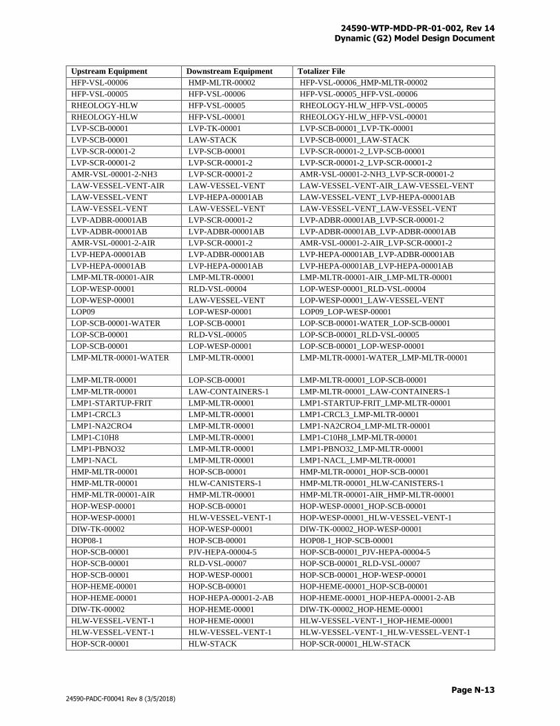
24590-WTP-MDD-PR-01-002, Rev 14 Dynamic (G2) Model Design Document
Page N-13
24590-PADC-F00041 Rev 8 (3/5/2018)
Upstream Equipment Downstream Equipment Totalizer File
HFP-VSL-00006 HMP-MLTR-00002 HFP-VSL-00006_HMP-MLTR-00002
HFP-VSL-00005 HFP-VSL-00006 HFP-VSL-00005_HFP-VSL-00006
RHEOLOGY-HLW HFP-VSL-00005 RHEOLOGY-HLW_HFP-VSL-00005
RHEOLOGY-HLW HFP-VSL-00001 RHEOLOGY-HLW_HFP-VSL-00001
LVP-SCB-00001 LVP-TK-00001 LVP-SCB-00001_LVP-TK-00001
LVP-SCB-00001 LAW-STACK LVP-SCB-00001_LAW-STACK
LVP-SCR-00001-2 LVP-SCB-00001 LVP-SCR-00001-2_LVP-SCB-00001
LVP-SCR-00001-2 LVP-SCR-00001-2 LVP-SCR-00001-2_LVP-SCR-00001-2
AMR-VSL-00001-2-NH3 LVP-SCR-00001-2 AMR-VSL-00001-2-NH3_LVP-SCR-00001-2
LAW-VESSEL-VENT-AIR LAW-VESSEL-VENT LAW-VESSEL-VENT-AIR_LAW-VESSEL-VENT
LAW-VESSEL-VENT LVP-HEPA-00001AB LAW-VESSEL-VENT_LVP-HEPA-00001AB
LAW-VESSEL-VENT LAW-VESSEL-VENT LAW-VESSEL-VENT_LAW-VESSEL-VENT
LVP-ADBR-00001AB LVP-SCR-00001-2 LVP-ADBR-00001AB_LVP-SCR-00001-2
LVP-ADBR-00001AB LVP-ADBR-00001AB LVP-ADBR-00001AB_LVP-ADBR-00001AB
AMR-VSL-00001-2-AIR LVP-SCR-00001-2 AMR-VSL-00001-2-AIR_LVP-SCR-00001-2
LVP-HEPA-00001AB LVP-ADBR-00001AB LVP-HEPA-00001AB_LVP-ADBR-00001AB
LVP-HEPA-00001AB LVP-HEPA-00001AB LVP-HEPA-00001AB_LVP-HEPA-00001AB
LMP-MLTR-00001-AIR LMP-MLTR-00001 LMP-MLTR-00001-AIR_LMP-MLTR-00001
LOP-WESP-00001 RLD-VSL-00004 LOP-WESP-00001_RLD-VSL-00004
LOP-WESP-00001 LAW-VESSEL-VENT LOP-WESP-00001_LAW-VESSEL-VENT
LOP09 LOP-WESP-00001 LOP09_LOP-WESP-00001
LOP-SCB-00001-WATER LOP-SCB-00001 LOP-SCB-00001-WATER_LOP-SCB-00001
LOP-SCB-00001 RLD-VSL-00005 LOP-SCB-00001_RLD-VSL-00005
LOP-SCB-00001 LOP-WESP-00001 LOP-SCB-00001_LOP-WESP-00001
LMP-MLTR-00001-WATER LMP-MLTR-00001 LMP-MLTR-00001-WATER_LMP-MLTR-00001
LMP-MLTR-00001 LOP-SCB-00001 LMP-MLTR-00001_LOP-SCB-00001
LMP-MLTR-00001 LAW-CONTAINERS-1 LMP-MLTR-00001_LAW-CONTAINERS-1
LMP1-STARTUP-FRIT LMP-MLTR-00001 LMP1-STARTUP-FRIT_LMP-MLTR-00001
LMP1-CRCL3 LMP-MLTR-00001 LMP1-CRCL3_LMP-MLTR-00001
LMP1-NA2CRO4 LMP-MLTR-00001 LMP1-NA2CRO4_LMP-MLTR-00001
LMP1-C10H8 LMP-MLTR-00001 LMP1-C10H8_LMP-MLTR-00001
LMP1-PBNO32 LMP-MLTR-00001 LMP1-PBNO32_LMP-MLTR-00001
LMP1-NACL LMP-MLTR-00001 LMP1-NACL_LMP-MLTR-00001
HMP-MLTR-00001 HOP-SCB-00001 HMP-MLTR-00001_HOP-SCB-00001
HMP-MLTR-00001 HLW-CANISTERS-1 HMP-MLTR-00001_HLW-CANISTERS-1
HMP-MLTR-00001-AIR HMP-MLTR-00001 HMP-MLTR-00001-AIR_HMP-MLTR-00001
HOP-WESP-00001 HOP-SCB-00001 HOP-WESP-00001_HOP-SCB-00001
HOP-WESP-00001 HLW-VESSEL-VENT-1 HOP-WESP-00001_HLW-VESSEL-VENT-1
DIW-TK-00002 HOP-WESP-00001 DIW-TK-00002_HOP-WESP-00001
HOP08-1 HOP-SCB-00001 HOP08-1_HOP-SCB-00001
HOP-SCB-00001 PJV-HEPA-00004-5 HOP-SCB-00001_PJV-HEPA-00004-5
HOP-SCB-00001 RLD-VSL-00007 HOP-SCB-00001_RLD-VSL-00007
HOP-SCB-00001 HOP-WESP-00001 HOP-SCB-00001_HOP-WESP-00001
HOP-HEME-00001 HOP-SCB-00001 HOP-HEME-00001_HOP-SCB-00001
HOP-HEME-00001 HOP-HEPA-00001-2-AB HOP-HEME-00001_HOP-HEPA-00001-2-AB
DIW-TK-00002 HOP-HEME-00001 DIW-TK-00002_HOP-HEME-00001
HLW-VESSEL-VENT-1 HOP-HEME-00001 HLW-VESSEL-VENT-1_HOP-HEME-00001
HLW-VESSEL-VENT-1 HLW-VESSEL-VENT-1 HLW-VESSEL-VENT-1_HLW-VESSEL-VENT-1
HOP-SCR-00001 HLW-STACK HOP-SCR-00001_HLW-STACK
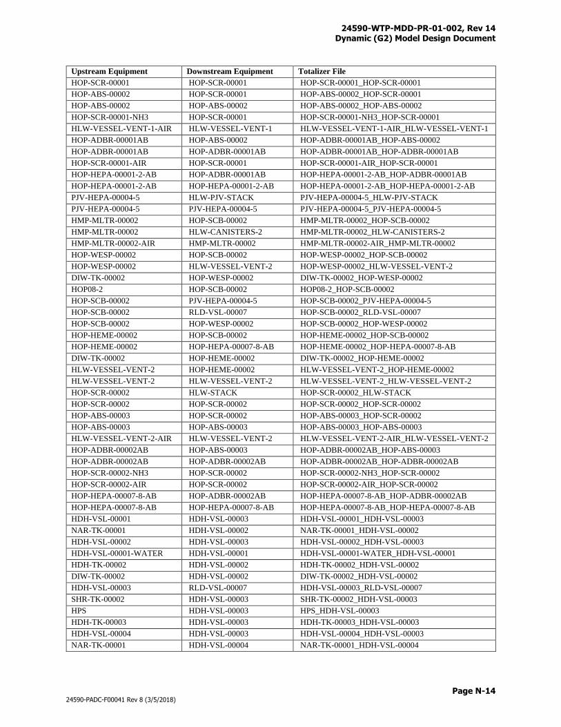
24590-WTP-MDD-PR-01-002, Rev 14 Dynamic (G2) Model Design Document
Page N-14
24590-PADC-F00041 Rev 8 (3/5/2018)
Upstream Equipment Downstream Equipment Totalizer File
HOP-SCR-00001 HOP-SCR-00001 HOP-SCR-00001_HOP-SCR-00001
HOP-ABS-00002 HOP-SCR-00001 HOP-ABS-00002_HOP-SCR-00001
HOP-ABS-00002 HOP-ABS-00002 HOP-ABS-00002_HOP-ABS-00002
HOP-SCR-00001-NH3 HOP-SCR-00001 HOP-SCR-00001-NH3_HOP-SCR-00001
HLW-VESSEL-VENT-1-AIR HLW-VESSEL-VENT-1 HLW-VESSEL-VENT-1-AIR_HLW-VESSEL-VENT-1
HOP-ADBR-00001AB HOP-ABS-00002 HOP-ADBR-00001AB_HOP-ABS-00002
HOP-ADBR-00001AB HOP-ADBR-00001AB HOP-ADBR-00001AB_HOP-ADBR-00001AB
HOP-SCR-00001-AIR HOP-SCR-00001 HOP-SCR-00001-AIR_HOP-SCR-00001
HOP-HEPA-00001-2-AB HOP-ADBR-00001AB HOP-HEPA-00001-2-AB_HOP-ADBR-00001AB
HOP-HEPA-00001-2-AB HOP-HEPA-00001-2-AB HOP-HEPA-00001-2-AB_HOP-HEPA-00001-2-AB
PJV-HEPA-00004-5 HLW-PJV-STACK PJV-HEPA-00004-5_HLW-PJV-STACK
PJV-HEPA-00004-5 PJV-HEPA-00004-5 PJV-HEPA-00004-5_PJV-HEPA-00004-5
HMP-MLTR-00002 HOP-SCB-00002 HMP-MLTR-00002_HOP-SCB-00002
HMP-MLTR-00002 HLW-CANISTERS-2 HMP-MLTR-00002_HLW-CANISTERS-2
HMP-MLTR-00002-AIR HMP-MLTR-00002 HMP-MLTR-00002-AIR_HMP-MLTR-00002
HOP-WESP-00002 HOP-SCB-00002 HOP-WESP-00002_HOP-SCB-00002
HOP-WESP-00002 HLW-VESSEL-VENT-2 HOP-WESP-00002_HLW-VESSEL-VENT-2
DIW-TK-00002 HOP-WESP-00002 DIW-TK-00002_HOP-WESP-00002
HOP08-2 HOP-SCB-00002 HOP08-2_HOP-SCB-00002
HOP-SCB-00002 PJV-HEPA-00004-5 HOP-SCB-00002_PJV-HEPA-00004-5
HOP-SCB-00002 RLD-VSL-00007 HOP-SCB-00002_RLD-VSL-00007
HOP-SCB-00002 HOP-WESP-00002 HOP-SCB-00002_HOP-WESP-00002
HOP-HEME-00002 HOP-SCB-00002 HOP-HEME-00002_HOP-SCB-00002
HOP-HEME-00002 HOP-HEPA-00007-8-AB HOP-HEME-00002_HOP-HEPA-00007-8-AB
DIW-TK-00002 HOP-HEME-00002 DIW-TK-00002_HOP-HEME-00002
HLW-VESSEL-VENT-2 HOP-HEME-00002 HLW-VESSEL-VENT-2_HOP-HEME-00002
HLW-VESSEL-VENT-2 HLW-VESSEL-VENT-2 HLW-VESSEL-VENT-2_HLW-VESSEL-VENT-2
HOP-SCR-00002 HLW-STACK HOP-SCR-00002_HLW-STACK
HOP-SCR-00002 HOP-SCR-00002 HOP-SCR-00002_HOP-SCR-00002
HOP-ABS-00003 HOP-SCR-00002 HOP-ABS-00003_HOP-SCR-00002
HOP-ABS-00003 HOP-ABS-00003 HOP-ABS-00003_HOP-ABS-00003
HLW-VESSEL-VENT-2-AIR HLW-VESSEL-VENT-2 HLW-VESSEL-VENT-2-AIR_HLW-VESSEL-VENT-2
HOP-ADBR-00002AB HOP-ABS-00003 HOP-ADBR-00002AB_HOP-ABS-00003
HOP-ADBR-00002AB HOP-ADBR-00002AB HOP-ADBR-00002AB_HOP-ADBR-00002AB
HOP-SCR-00002-NH3 HOP-SCR-00002 HOP-SCR-00002-NH3_HOP-SCR-00002
HOP-SCR-00002-AIR HOP-SCR-00002 HOP-SCR-00002-AIR_HOP-SCR-00002
HOP-HEPA-00007-8-AB HOP-ADBR-00002AB HOP-HEPA-00007-8-AB_HOP-ADBR-00002AB
HOP-HEPA-00007-8-AB HOP-HEPA-00007-8-AB HOP-HEPA-00007-8-AB_HOP-HEPA-00007-8-AB
HDH-VSL-00001 HDH-VSL-00003 HDH-VSL-00001_HDH-VSL-00003
NAR-TK-00001 HDH-VSL-00002 NAR-TK-00001_HDH-VSL-00002
HDH-VSL-00002 HDH-VSL-00003 HDH-VSL-00002_HDH-VSL-00003
HDH-VSL-00001-WATER HDH-VSL-00001 HDH-VSL-00001-WATER_HDH-VSL-00001
HDH-TK-00002 HDH-VSL-00002 HDH-TK-00002_HDH-VSL-00002
DIW-TK-00002 HDH-VSL-00002 DIW-TK-00002_HDH-VSL-00002
HDH-VSL-00003 RLD-VSL-00007 HDH-VSL-00003_RLD-VSL-00007
SHR-TK-00002 HDH-VSL-00003 SHR-TK-00002_HDH-VSL-00003
HPS HDH-VSL-00003 HPS_HDH-VSL-00003
HDH-TK-00003 HDH-VSL-00003 HDH-TK-00003_HDH-VSL-00003
HDH-VSL-00004 HDH-VSL-00003 HDH-VSL-00004_HDH-VSL-00003
NAR-TK-00001 HDH-VSL-00004 NAR-TK-00001_HDH-VSL-00004
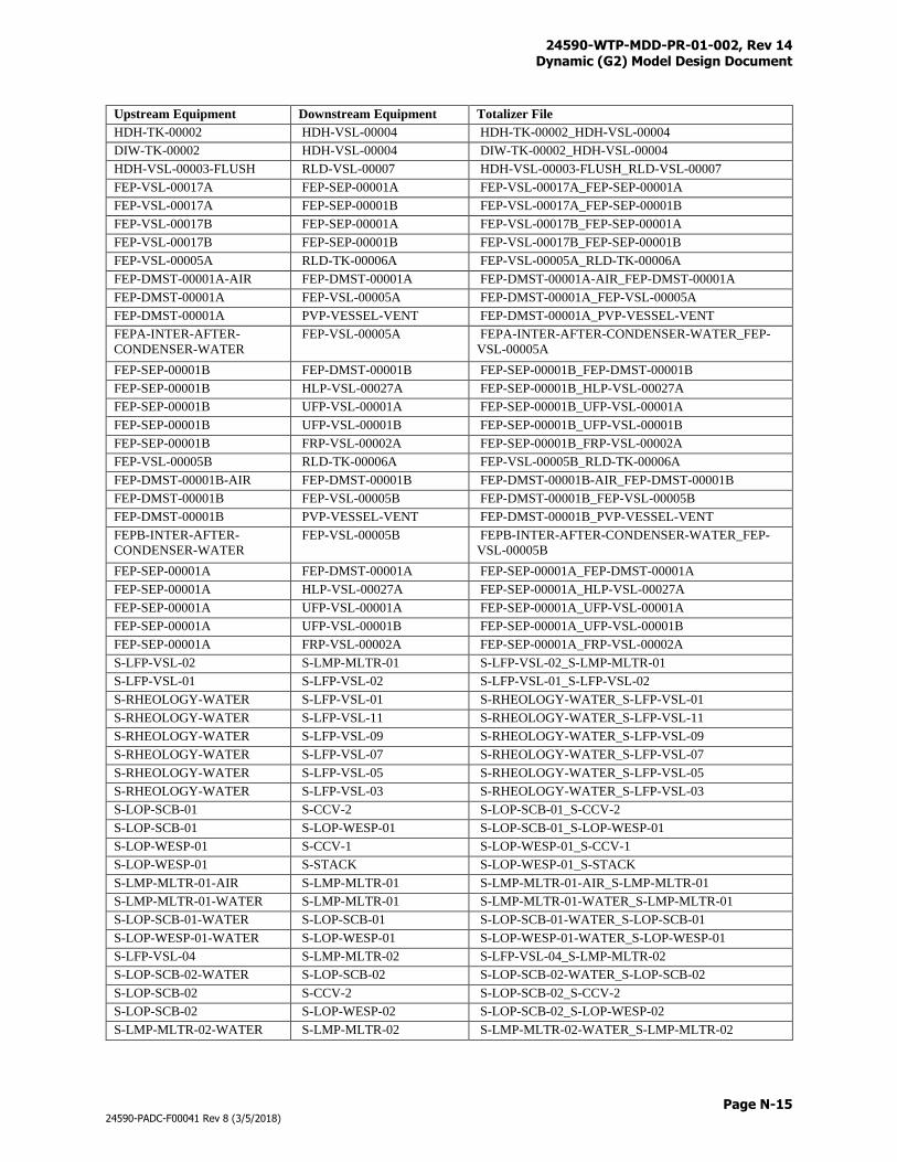
24590-WTP-MDD-PR-01-002, Rev 14 Dynamic (G2) Model Design Document
Page N-15
24590-PADC-F00041 Rev 8 (3/5/2018)
Upstream Equipment Downstream Equipment Totalizer File
HDH-TK-00002 HDH-VSL-00004 HDH-TK-00002_HDH-VSL-00004
DIW-TK-00002 HDH-VSL-00004 DIW-TK-00002_HDH-VSL-00004
HDH-VSL-00003-FLUSH RLD-VSL-00007 HDH-VSL-00003-FLUSH_RLD-VSL-00007
FEP-VSL-00017A FEP-SEP-00001A FEP-VSL-00017A_FEP-SEP-00001A
FEP-VSL-00017A FEP-SEP-00001B FEP-VSL-00017A_FEP-SEP-00001B
FEP-VSL-00017B FEP-SEP-00001A FEP-VSL-00017B_FEP-SEP-00001A
FEP-VSL-00017B FEP-SEP-00001B FEP-VSL-00017B_FEP-SEP-00001B
FEP-VSL-00005A RLD-TK-00006A FEP-VSL-00005A_RLD-TK-00006A
FEP-DMST-00001A-AIR FEP-DMST-00001A FEP-DMST-00001A-AIR_FEP-DMST-00001A
FEP-DMST-00001A FEP-VSL-00005A FEP-DMST-00001A_FEP-VSL-00005A
FEP-DMST-00001A PVP-VESSEL-VENT FEP-DMST-00001A_PVP-VESSEL-VENT
FEPA-INTER-AFTER-
CONDENSER-WATER
FEP-VSL-00005A FEPA-INTER-AFTER-CONDENSER-WATER_FEP-
VSL-00005A
FEP-SEP-00001B FEP-DMST-00001B FEP-SEP-00001B_FEP-DMST-00001B
FEP-SEP-00001B HLP-VSL-00027A FEP-SEP-00001B_HLP-VSL-00027A
FEP-SEP-00001B UFP-VSL-00001A FEP-SEP-00001B_UFP-VSL-00001A
FEP-SEP-00001B UFP-VSL-00001B FEP-SEP-00001B_UFP-VSL-00001B
FEP-SEP-00001B FRP-VSL-00002A FEP-SEP-00001B_FRP-VSL-00002A
FEP-VSL-00005B RLD-TK-00006A FEP-VSL-00005B_RLD-TK-00006A
FEP-DMST-00001B-AIR FEP-DMST-00001B FEP-DMST-00001B-AIR_FEP-DMST-00001B
FEP-DMST-00001B FEP-VSL-00005B FEP-DMST-00001B_FEP-VSL-00005B
FEP-DMST-00001B PVP-VESSEL-VENT FEP-DMST-00001B_PVP-VESSEL-VENT
FEPB-INTER-AFTER-
CONDENSER-WATER
FEP-VSL-00005B FEPB-INTER-AFTER-CONDENSER-WATER_FEP-
VSL-00005B
FEP-SEP-00001A FEP-DMST-00001A FEP-SEP-00001A_FEP-DMST-00001A
FEP-SEP-00001A HLP-VSL-00027A FEP-SEP-00001A_HLP-VSL-00027A
FEP-SEP-00001A UFP-VSL-00001A FEP-SEP-00001A_UFP-VSL-00001A
FEP-SEP-00001A UFP-VSL-00001B FEP-SEP-00001A_UFP-VSL-00001B
FEP-SEP-00001A FRP-VSL-00002A FEP-SEP-00001A_FRP-VSL-00002A
S-LFP-VSL-02 S-LMP-MLTR-01 S-LFP-VSL-02_S-LMP-MLTR-01
S-LFP-VSL-01 S-LFP-VSL-02 S-LFP-VSL-01_S-LFP-VSL-02
S-RHEOLOGY-WATER S-LFP-VSL-01 S-RHEOLOGY-WATER_S-LFP-VSL-01
S-RHEOLOGY-WATER S-LFP-VSL-11 S-RHEOLOGY-WATER_S-LFP-VSL-11
S-RHEOLOGY-WATER S-LFP-VSL-09 S-RHEOLOGY-WATER_S-LFP-VSL-09
S-RHEOLOGY-WATER S-LFP-VSL-07 S-RHEOLOGY-WATER_S-LFP-VSL-07
S-RHEOLOGY-WATER S-LFP-VSL-05 S-RHEOLOGY-WATER_S-LFP-VSL-05
S-RHEOLOGY-WATER S-LFP-VSL-03 S-RHEOLOGY-WATER_S-LFP-VSL-03
S-LOP-SCB-01 S-CCV-2 S-LOP-SCB-01_S-CCV-2
S-LOP-SCB-01 S-LOP-WESP-01 S-LOP-SCB-01_S-LOP-WESP-01
S-LOP-WESP-01 S-CCV-1 S-LOP-WESP-01_S-CCV-1
S-LOP-WESP-01 S-STACK S-LOP-WESP-01_S-STACK
S-LMP-MLTR-01-AIR S-LMP-MLTR-01 S-LMP-MLTR-01-AIR_S-LMP-MLTR-01
S-LMP-MLTR-01-WATER S-LMP-MLTR-01 S-LMP-MLTR-01-WATER_S-LMP-MLTR-01
S-LOP-SCB-01-WATER S-LOP-SCB-01 S-LOP-SCB-01-WATER_S-LOP-SCB-01
S-LOP-WESP-01-WATER S-LOP-WESP-01 S-LOP-WESP-01-WATER_S-LOP-WESP-01
S-LFP-VSL-04 S-LMP-MLTR-02 S-LFP-VSL-04_S-LMP-MLTR-02
S-LOP-SCB-02-WATER S-LOP-SCB-02 S-LOP-SCB-02-WATER_S-LOP-SCB-02
S-LOP-SCB-02 S-CCV-2 S-LOP-SCB-02_S-CCV-2
S-LOP-SCB-02 S-LOP-WESP-02 S-LOP-SCB-02_S-LOP-WESP-02
S-LMP-MLTR-02-WATER S-LMP-MLTR-02 S-LMP-MLTR-02-WATER_S-LMP-MLTR-02
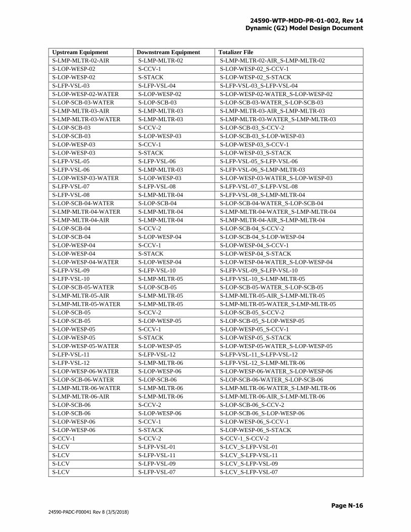
24590-WTP-MDD-PR-01-002, Rev 14 Dynamic (G2) Model Design Document
Page N-16
24590-PADC-F00041 Rev 8 (3/5/2018)
Upstream Equipment Downstream Equipment Totalizer File
S-LMP-MLTR-02-AIR S-LMP-MLTR-02 S-LMP-MLTR-02-AIR_S-LMP-MLTR-02
S-LOP-WESP-02 S-CCV-1 S-LOP-WESP-02_S-CCV-1
S-LOP-WESP-02 S-STACK S-LOP-WESP-02_S-STACK
S-LFP-VSL-03 S-LFP-VSL-04 S-LFP-VSL-03_S-LFP-VSL-04
S-LOP-WESP-02-WATER S-LOP-WESP-02 S-LOP-WESP-02-WATER_S-LOP-WESP-02
S-LOP-SCB-03-WATER S-LOP-SCB-03 S-LOP-SCB-03-WATER_S-LOP-SCB-03
S-LMP-MLTR-03-AIR S-LMP-MLTR-03 S-LMP-MLTR-03-AIR_S-LMP-MLTR-03
S-LMP-MLTR-03-WATER S-LMP-MLTR-03 S-LMP-MLTR-03-WATER_S-LMP-MLTR-03
S-LOP-SCB-03 S-CCV-2 S-LOP-SCB-03_S-CCV-2
S-LOP-SCB-03 S-LOP-WESP-03 S-LOP-SCB-03_S-LOP-WESP-03
S-LOP-WESP-03 S-CCV-1 S-LOP-WESP-03_S-CCV-1
S-LOP-WESP-03 S-STACK S-LOP-WESP-03_S-STACK
S-LFP-VSL-05 S-LFP-VSL-06 S-LFP-VSL-05_S-LFP-VSL-06
S-LFP-VSL-06 S-LMP-MLTR-03 S-LFP-VSL-06_S-LMP-MLTR-03
S-LOP-WESP-03-WATER S-LOP-WESP-03 S-LOP-WESP-03-WATER_S-LOP-WESP-03
S-LFP-VSL-07 S-LFP-VSL-08 S-LFP-VSL-07_S-LFP-VSL-08
S-LFP-VSL-08 S-LMP-MLTR-04 S-LFP-VSL-08_S-LMP-MLTR-04
S-LOP-SCB-04-WATER S-LOP-SCB-04 S-LOP-SCB-04-WATER_S-LOP-SCB-04
S-LMP-MLTR-04-WATER S-LMP-MLTR-04 S-LMP-MLTR-04-WATER_S-LMP-MLTR-04
S-LMP-MLTR-04-AIR S-LMP-MLTR-04 S-LMP-MLTR-04-AIR_S-LMP-MLTR-04
S-LOP-SCB-04 S-CCV-2 S-LOP-SCB-04_S-CCV-2
S-LOP-SCB-04 S-LOP-WESP-04 S-LOP-SCB-04_S-LOP-WESP-04
S-LOP-WESP-04 S-CCV-1 S-LOP-WESP-04_S-CCV-1
S-LOP-WESP-04 S-STACK S-LOP-WESP-04_S-STACK
S-LOP-WESP-04-WATER S-LOP-WESP-04 S-LOP-WESP-04-WATER_S-LOP-WESP-04
S-LFP-VSL-09 S-LFP-VSL-10 S-LFP-VSL-09_S-LFP-VSL-10
S-LFP-VSL-10 S-LMP-MLTR-05 S-LFP-VSL-10_S-LMP-MLTR-05
S-LOP-SCB-05-WATER S-LOP-SCB-05 S-LOP-SCB-05-WATER_S-LOP-SCB-05
S-LMP-MLTR-05-AIR S-LMP-MLTR-05 S-LMP-MLTR-05-AIR_S-LMP-MLTR-05
S-LMP-MLTR-05-WATER S-LMP-MLTR-05 S-LMP-MLTR-05-WATER_S-LMP-MLTR-05
S-LOP-SCB-05 S-CCV-2 S-LOP-SCB-05_S-CCV-2
S-LOP-SCB-05 S-LOP-WESP-05 S-LOP-SCB-05_S-LOP-WESP-05
S-LOP-WESP-05 S-CCV-1 S-LOP-WESP-05_S-CCV-1
S-LOP-WESP-05 S-STACK S-LOP-WESP-05_S-STACK
S-LOP-WESP-05-WATER S-LOP-WESP-05 S-LOP-WESP-05-WATER_S-LOP-WESP-05
S-LFP-VSL-11 S-LFP-VSL-12 S-LFP-VSL-11_S-LFP-VSL-12
S-LFP-VSL-12 S-LMP-MLTR-06 S-LFP-VSL-12_S-LMP-MLTR-06
S-LOP-WESP-06-WATER S-LOP-WESP-06 S-LOP-WESP-06-WATER_S-LOP-WESP-06
S-LOP-SCB-06-WATER S-LOP-SCB-06 S-LOP-SCB-06-WATER_S-LOP-SCB-06
S-LMP-MLTR-06-WATER S-LMP-MLTR-06 S-LMP-MLTR-06-WATER_S-LMP-MLTR-06
S-LMP-MLTR-06-AIR S-LMP-MLTR-06 S-LMP-MLTR-06-AIR_S-LMP-MLTR-06
S-LOP-SCB-06 S-CCV-2 S-LOP-SCB-06_S-CCV-2
S-LOP-SCB-06 S-LOP-WESP-06 S-LOP-SCB-06_S-LOP-WESP-06
S-LOP-WESP-06 S-CCV-1 S-LOP-WESP-06_S-CCV-1
S-LOP-WESP-06 S-STACK S-LOP-WESP-06_S-STACK
S-CCV-1 S-CCV-2 S-CCV-1_S-CCV-2
S-LCV S-LFP-VSL-01 S-LCV_S-LFP-VSL-01
S-LCV S-LFP-VSL-11 S-LCV_S-LFP-VSL-11
S-LCV S-LFP-VSL-09 S-LCV_S-LFP-VSL-09
S-LCV S-LFP-VSL-07 S-LCV_S-LFP-VSL-07
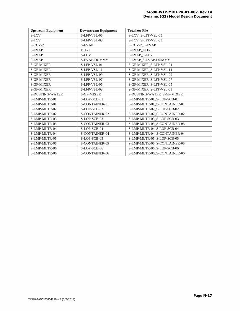
24590-WTP-MDD-PR-01-002, Rev 14 Dynamic (G2) Model Design Document
Page N-17
24590-PADC-F00041 Rev 8 (3/5/2018)
Upstream Equipment Downstream Equipment Totalizer File
S-LCV S-LFP-VSL-05 S-LCV_S-LFP-VSL-05
S-LCV S-LFP-VSL-03 S-LCV_S-LFP-VSL-03
S-CCV-2 S-EVAP S-CCV-2_S-EVAP
S-EVAP ETF-1 S-EVAP_ETF-1
S-EVAP S-LCV S-EVAP_S-LCV
S-EVAP S-EVAP-DUMMY S-EVAP_S-EVAP-DUMMY
S-GF-MIXER S-LFP-VSL-01 S-GF-MIXER_S-LFP-VSL-01
S-GF-MIXER S-LFP-VSL-11 S-GF-MIXER_S-LFP-VSL-11
S-GF-MIXER S-LFP-VSL-09 S-GF-MIXER_S-LFP-VSL-09
S-GF-MIXER S-LFP-VSL-07 S-GF-MIXER_S-LFP-VSL-07
S-GF-MIXER S-LFP-VSL-05 S-GF-MIXER_S-LFP-VSL-05
S-GF-MIXER S-LFP-VSL-03 S-GF-MIXER_S-LFP-VSL-03
S-DUSTING-WATER S-GF-MIXER S-DUSTING-WATER_S-GF-MIXER
S-LMP-MLTR-01 S-LOP-SCB-01 S-LMP-MLTR-01_S-LOP-SCB-01
S-LMP-MLTR-01 S-CONTAINER-01 S-LMP-MLTR-01_S-CONTAINER-01
S-LMP-MLTR-02 S-LOP-SCB-02 S-LMP-MLTR-02_S-LOP-SCB-02
S-LMP-MLTR-02 S-CONTAINER-02 S-LMP-MLTR-02_S-CONTAINER-02
S-LMP-MLTR-03 S-LOP-SCB-03 S-LMP-MLTR-03_S-LOP-SCB-03
S-LMP-MLTR-03 S-CONTAINER-03 S-LMP-MLTR-03_S-CONTAINER-03
S-LMP-MLTR-04 S-LOP-SCB-04 S-LMP-MLTR-04_S-LOP-SCB-04
S-LMP-MLTR-04 S-CONTAINER-04 S-LMP-MLTR-04_S-CONTAINER-04
S-LMP-MLTR-05 S-LOP-SCB-05 S-LMP-MLTR-05_S-LOP-SCB-05
S-LMP-MLTR-05 S-CONTAINER-05 S-LMP-MLTR-05_S-CONTAINER-05
S-LMP-MLTR-06 S-LOP-SCB-06 S-LMP-MLTR-06_S-LOP-SCB-06
S-LMP-MLTR-06 S-CONTAINER-06 S-LMP-MLTR-06_S-CONTAINER-06

24590-WTP-MDD-PR-01-002, Rev 14 Dynamic (G2) Model Design Document
Page O-i
24590-PADC-F00041 Rev 8 (3/5/2018)
Appendix O
History Sheet
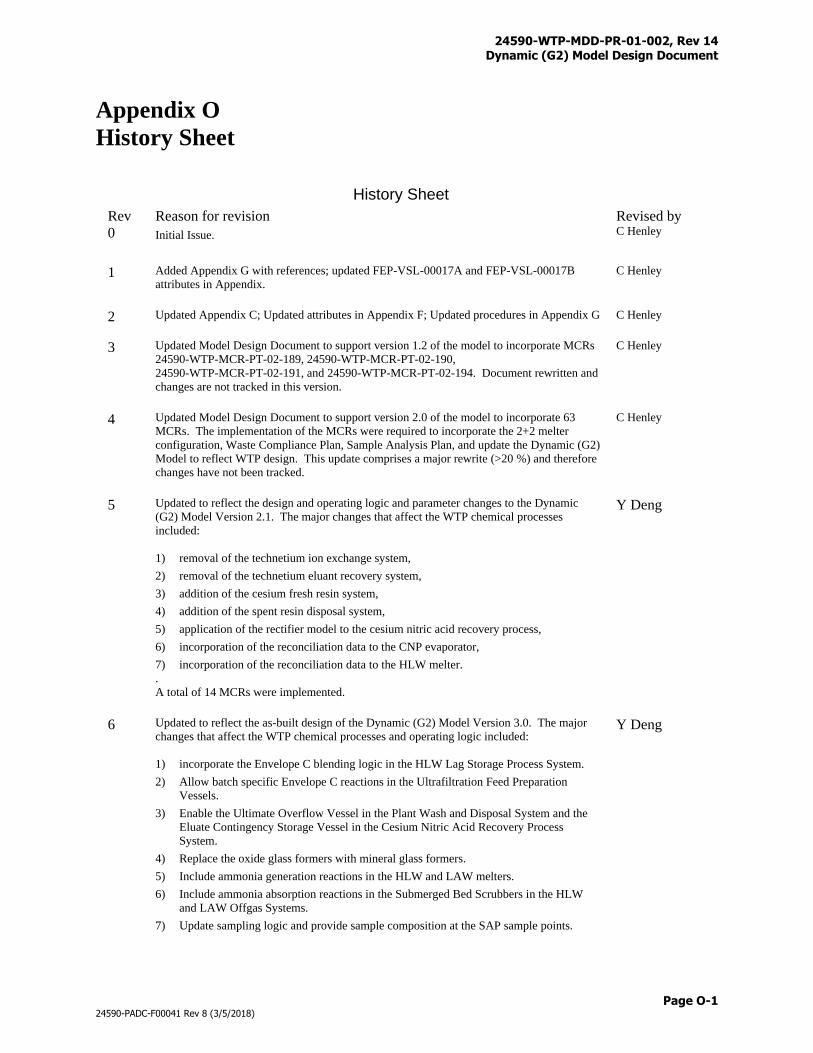
24590-WTP-MDD-PR-01-002, Rev 14 Dynamic (G2) Model Design Document
Page O-1
24590-PADC-F00041 Rev 8 (3/5/2018)
Appendix O
History Sheet
History Sheet
Rev Reason for revision Revised by
0 Initial Issue.
C Henley
1 Added Appendix G with references; updated FEP-VSL-00017A and FEP-VSL-00017B
attributes in Appendix.
C Henley
2 Updated Appendix C; Updated attributes in Appendix F; Updated procedures in Appendix G
C Henley
3 Updated Model Design Document to support version 1.2 of the model to incorporate MCRs
24590-WTP-MCR-PT-02-189, 24590-WTP-MCR-PT-02-190,
24590-WTP-MCR-PT-02-191, and 24590-WTP-MCR-PT-02-194. Document rewritten and
changes are not tracked in this version.
C Henley
4 Updated Model Design Document to support version 2.0 of the model to incorporate 63
MCRs. The implementation of the MCRs were required to incorporate the 2+2 melter
configuration, Waste Compliance Plan, Sample Analysis Plan, and update the Dynamic (G2)
Model to reflect WTP design. This update comprises a major rewrite (>20 %) and therefore
changes have not been tracked.
C Henley
5 Updated to reflect the design and operating logic and parameter changes to the Dynamic
(G2) Model Version 2.1. The major changes that affect the WTP chemical processes
included:
1) removal of the technetium ion exchange system,
2) removal of the technetium eluant recovery system,
3) addition of the cesium fresh resin system,
4) addition of the spent resin disposal system,
5) application of the rectifier model to the cesium nitric acid recovery process,
6) incorporation of the reconciliation data to the CNP evaporator,
7) incorporation of the reconciliation data to the HLW melter.
.
A total of 14 MCRs were implemented.
Y Deng
6 Updated to reflect the as-built design of the Dynamic (G2) Model Version 3.0. The major
changes that affect the WTP chemical processes and operating logic included:
1) incorporate the Envelope C blending logic in the HLW Lag Storage Process System.
2) Allow batch specific Envelope C reactions in the Ultrafiltration Feed Preparation
Vessels.
3) Enable the Ultimate Overflow Vessel in the Plant Wash and Disposal System and the
Eluate Contingency Storage Vessel in the Cesium Nitric Acid Recovery Process
System.
4) Replace the oxide glass formers with mineral glass formers.
5) Include ammonia generation reactions in the HLW and LAW melters.
6) Include ammonia absorption reactions in the Submerged Bed Scrubbers in the HLW
and LAW Offgas Systems.
7) Update sampling logic and provide sample composition at the SAP sample points.
Y Deng
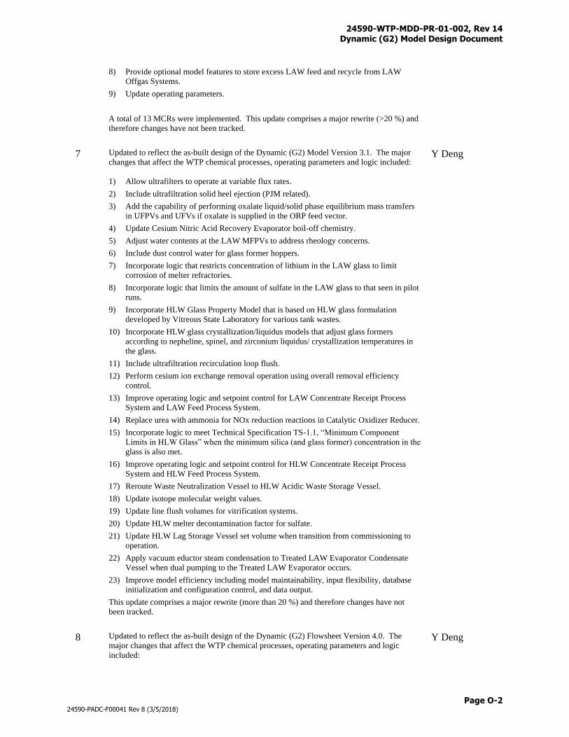
24590-WTP-MDD-PR-01-002, Rev 14 Dynamic (G2) Model Design Document
Page O-2
24590-PADC-F00041 Rev 8 (3/5/2018)
8) Provide optional model features to store excess LAW feed and recycle from LAW
Offgas Systems.
9) Update operating parameters.
A total of 13 MCRs were implemented. This update comprises a major rewrite (>20 %) and
therefore changes have not been tracked.
7 Updated to reflect the as-built design of the Dynamic (G2) Model Version 3.1. The major
changes that affect the WTP chemical processes, operating parameters and logic included:
1) Allow ultrafilters to operate at variable flux rates.
2) Include ultrafiltration solid heel ejection (PJM related).
3) Add the capability of performing oxalate liquid/solid phase equilibrium mass transfers
in UFPVs and UFVs if oxalate is supplied in the ORP feed vector.
4) Update Cesium Nitric Acid Recovery Evaporator boil-off chemistry.
5) Adjust water contents at the LAW MFPVs to address rheology concerns.
6) Include dust control water for glass former hoppers.
7) Incorporate logic that restricts concentration of lithium in the LAW glass to limit
corrosion of melter refractories.
8) Incorporate logic that limits the amount of sulfate in the LAW glass to that seen in pilot
runs.
9) Incorporate HLW Glass Property Model that is based on HLW glass formulation
developed by Vitreous State Laboratory for various tank wastes.
10) Incorporate HLW glass crystallization/liquidus models that adjust glass formers
according to nepheline, spinel, and zirconium liquidus/ crystallization temperatures in
the glass.
11) Include ultrafiltration recirculation loop flush.
12) Perform cesium ion exchange removal operation using overall removal efficiency
control.
13) Improve operating logic and setpoint control for LAW Concentrate Receipt Process
System and LAW Feed Process System.
14) Replace urea with ammonia for NOx reduction reactions in Catalytic Oxidizer Reducer.
15) Incorporate logic to meet Technical Specification TS-1.1, “Minimum Component
Limits in HLW Glass” when the minimum silica (and glass former) concentration in the
glass is also met.
16) Improve operating logic and setpoint control for HLW Concentrate Receipt Process
System and HLW Feed Process System.
17) Reroute Waste Neutralization Vessel to HLW Acidic Waste Storage Vessel.
18) Update isotope molecular weight values.
19) Update line flush volumes for vitrification systems.
20) Update HLW melter decontamination factor for sulfate.
21) Update HLW Lag Storage Vessel set volume when transition from commissioning to
operation.
22) Apply vacuum eductor steam condensation to Treated LAW Evaporator Condensate
Vessel when dual pumping to the Treated LAW Evaporator occurs.
23) Improve model efficiency including model maintainability, input flexibility, database
initialization and configuration control, and data output.
This update comprises a major rewrite (more than 20 %) and therefore changes have not
been tracked.
Y Deng
8 Updated to reflect the as-built design of the Dynamic (G2) Flowsheet Version 4.0. The
major changes that affect the WTP chemical processes, operating parameters and logic
included:
Y Deng
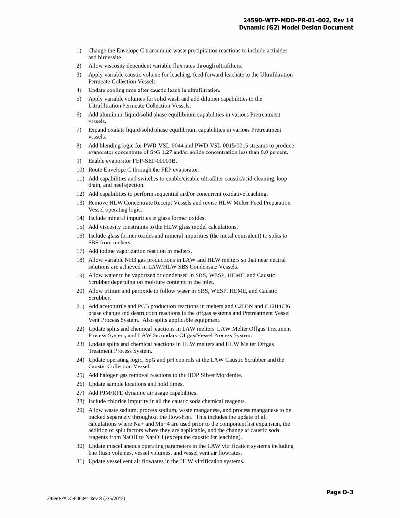
24590-WTP-MDD-PR-01-002, Rev 14 Dynamic (G2) Model Design Document
Page O-3
24590-PADC-F00041 Rev 8 (3/5/2018)
1) Change the Envelope C transuranic waste precipitation reactions to include actinides
and birnessite.
2) Allow viscosity dependent variable flux rates through ultrafilters.
3) Apply variable caustic volume for leaching, feed forward leachate to the Ultrafiltration
Permeate Collection Vessels.
4) Update cooling time after caustic leach in ultrafiltration.
5) Apply variable volumes for solid wash and add dilution capabilities to the
Ultrafiltration Permeate Collection Vessels.
6) Add aluminum liquid/solid phase equilibrium capabilities in various Pretreatment
vessels.
7) Expand oxalate liquid/solid phase equilibrium capabilities in various Pretreatment
vessels.
8) Add blending logic for PWD-VSL-0044 and PWD-VSL-0015/0016 streams to produce
evaporator concentrate of SpG 1.27 and/or solids concentration less than 8.0 percent.
9) Enable evaporator FEP-SEP-00001B.
10) Route Envelope C through the FEP evaporator.
11) Add capabilities and switches to enable/disable ultrafilter caustic/acid cleaning, loop
drain, and heel ejection.
12) Add capabilities to perform sequential and/or concurrent oxidative leaching.
13) Remove HLW Concentrate Receipt Vessels and revise HLW Melter Feed Preparation
Vessel operating logic.
14) Include mineral impurities in glass former oxides.
15) Add viscosity constraints to the HLW glass model calculations.
16) Include glass former oxides and mineral impurities (the metal equivalent) to splits to
SBS from melters.
17) Add iodine vaporization reaction in melters.
18) Allow variable NH3 gas productions in LAW and HLW melters so that near neutral
solutions are achieved in LAW/HLW SBS Condensate Vessels.
19) Allow water to be vaporized or condensed in SBS, WESP, HEME, and Caustic
Scrubber depending on moisture contents in the inlet.
20) Allow tritium and peroxide to follow water in SBS, WESP, HEME, and Caustic
Scrubber.
21) Add acetonitrile and PCB production reactions in melters and C2H3N and C12H4Cl6
phase change and destruction reactions in the offgas systems and Pretreatment Vessel
Vent Process System. Also splits applicable equipment.
22) Update splits and chemical reactions in LAW melters, LAW Melter Offgas Treatment
Process System, and LAW Secondary Offgas/Vessel Process System.
23) Update splits and chemical reactions in HLW melters and HLW Melter Offgas
Treatment Process System.
24) Update operating logic, SpG and pH controls at the LAW Caustic Scrubber and the
Caustic Collection Vessel.
25) Add halogen gas removal reactions to the HOP Silver Mordenite.
26) Update sample locations and hold times.
27) Add PJM/RFD dynamic air usage capabilities.
28) Include chloride impurity in all the caustic soda chemical reagents.
29) Allow waste sodium, process sodium, waste manganese, and process manganese to be
tracked separately throughout the flowsheet. This includes the update of all
calculations where Na+ and Mn+4 are used prior to the component list expansion, the
addition of split factors where they are applicable, and the change of caustic soda
reagents from NaOH to NapOH (except the caustic for leaching).
30) Update miscellaneous operating parameters in the LAW vitrification systems including
line flush volumes, vessel volumes, and vessel vent air flowrates.
31) Update vessel vent air flowrates in the HLW vitrification systems.
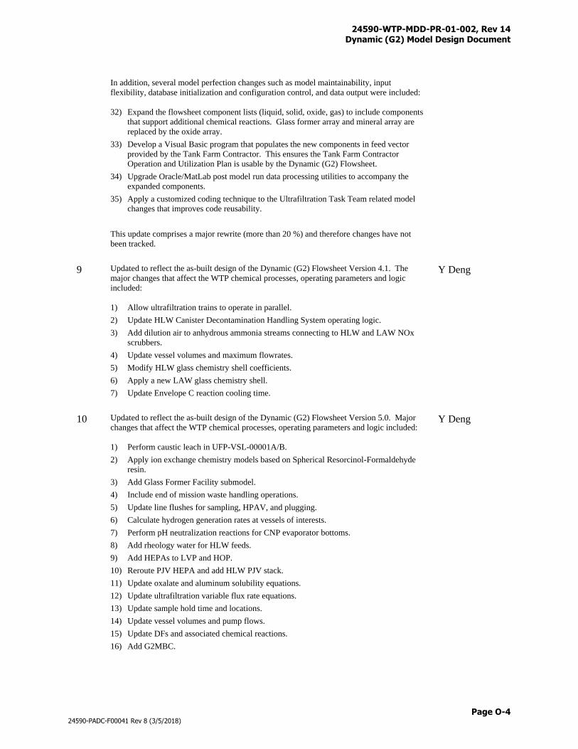
24590-WTP-MDD-PR-01-002, Rev 14 Dynamic (G2) Model Design Document
Page O-4
24590-PADC-F00041 Rev 8 (3/5/2018)
In addition, several model perfection changes such as model maintainability, input
flexibility, database initialization and configuration control, and data output were included:
32) Expand the flowsheet component lists (liquid, solid, oxide, gas) to include components
that support additional chemical reactions. Glass former array and mineral array are
replaced by the oxide array.
33) Develop a Visual Basic program that populates the new components in feed vector
provided by the Tank Farm Contractor. This ensures the Tank Farm Contractor
Operation and Utilization Plan is usable by the Dynamic (G2) Flowsheet.
34) Upgrade Oracle/MatLab post model run data processing utilities to accompany the
expanded components.
35) Apply a customized coding technique to the Ultrafiltration Task Team related model
changes that improves code reusability.
This update comprises a major rewrite (more than 20 %) and therefore changes have not
been tracked.
9 Updated to reflect the as-built design of the Dynamic (G2) Flowsheet Version 4.1. The
major changes that affect the WTP chemical processes, operating parameters and logic
included:
1) Allow ultrafiltration trains to operate in parallel.
2) Update HLW Canister Decontamination Handling System operating logic.
3) Add dilution air to anhydrous ammonia streams connecting to HLW and LAW NOx
scrubbers.
4) Update vessel volumes and maximum flowrates.
5) Modify HLW glass chemistry shell coefficients.
6) Apply a new LAW glass chemistry shell.
7) Update Envelope C reaction cooling time.
Y Deng
10 Updated to reflect the as-built design of the Dynamic (G2) Flowsheet Version 5.0. Major
changes that affect the WTP chemical processes, operating parameters and logic included:
1) Perform caustic leach in UFP-VSL-00001A/B.
2) Apply ion exchange chemistry models based on Spherical Resorcinol-Formaldehyde
resin.
3) Add Glass Former Facility submodel.
4) Include end of mission waste handling operations.
5) Update line flushes for sampling, HPAV, and plugging.
6) Calculate hydrogen generation rates at vessels of interests.
7) Perform pH neutralization reactions for CNP evaporator bottoms.
8) Add rheology water for HLW feeds.
9) Add HEPAs to LVP and HOP.
10) Reroute PJV HEPA and add HLW PJV stack.
11) Update oxalate and aluminum solubility equations.
12) Update ultrafiltration variable flux rate equations.
13) Update sample hold time and locations.
14) Update vessel volumes and pump flows.
15) Update DFs and associated chemical reactions.
16) Add G2MBC.
Y Deng
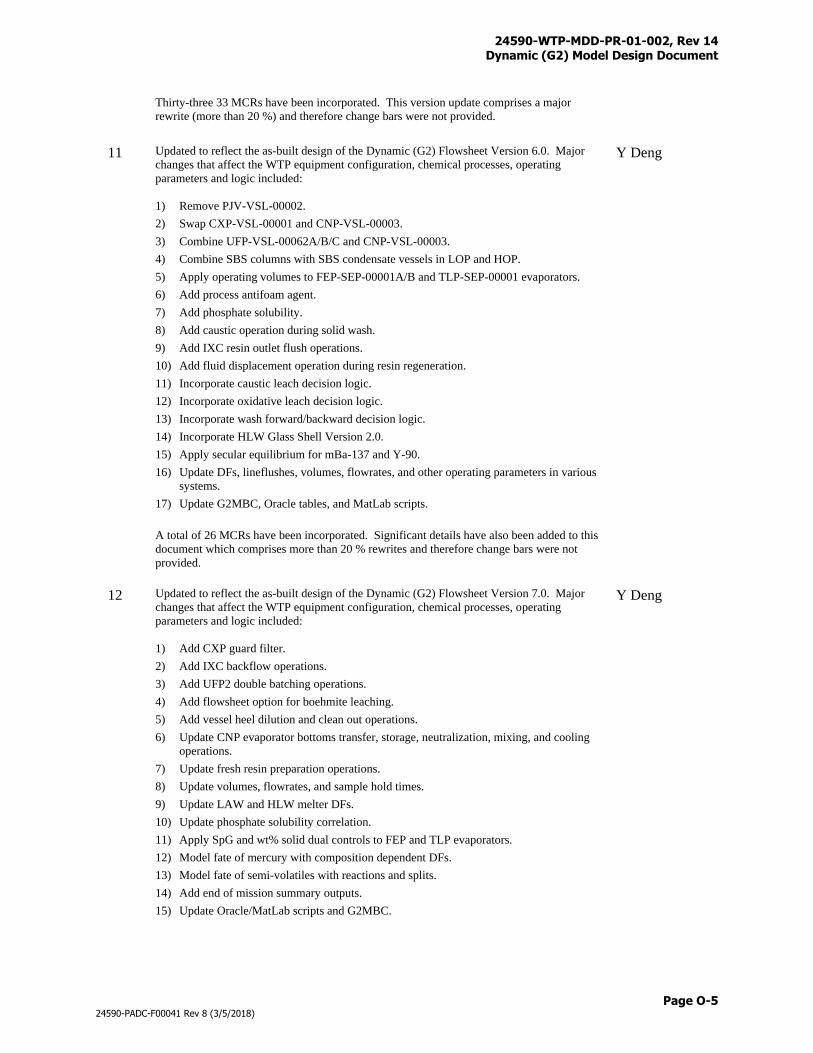
24590-WTP-MDD-PR-01-002, Rev 14 Dynamic (G2) Model Design Document
Page O-5
24590-PADC-F00041 Rev 8 (3/5/2018)
Thirty-three 33 MCRs have been incorporated. This version update comprises a major
rewrite (more than 20 %) and therefore change bars were not provided.
11 Updated to reflect the as-built design of the Dynamic (G2) Flowsheet Version 6.0. Major
changes that affect the WTP equipment configuration, chemical processes, operating
parameters and logic included:
1) Remove PJV-VSL-00002.
2) Swap CXP-VSL-00001 and CNP-VSL-00003.
3) Combine UFP-VSL-00062A/B/C and CNP-VSL-00003.
4) Combine SBS columns with SBS condensate vessels in LOP and HOP.
5) Apply operating volumes to FEP-SEP-00001A/B and TLP-SEP-00001 evaporators.
6) Add process antifoam agent.
7) Add phosphate solubility.
8) Add caustic operation during solid wash.
9) Add IXC resin outlet flush operations.
10) Add fluid displacement operation during resin regeneration.
11) Incorporate caustic leach decision logic.
12) Incorporate oxidative leach decision logic.
13) Incorporate wash forward/backward decision logic.
14) Incorporate HLW Glass Shell Version 2.0.
15) Apply secular equilibrium for mBa-137 and Y-90.
16) Update DFs, lineflushes, volumes, flowrates, and other operating parameters in various
systems.
17) Update G2MBC, Oracle tables, and MatLab scripts.
A total of 26 MCRs have been incorporated. Significant details have also been added to this
document which comprises more than 20 % rewrites and therefore change bars were not
provided.
Y Deng
12 Updated to reflect the as-built design of the Dynamic (G2) Flowsheet Version 7.0. Major
changes that affect the WTP equipment configuration, chemical processes, operating
parameters and logic included:
1) Add CXP guard filter.
2) Add IXC backflow operations.
3) Add UFP2 double batching operations.
4) Add flowsheet option for boehmite leaching.
5) Add vessel heel dilution and clean out operations.
6) Update CNP evaporator bottoms transfer, storage, neutralization, mixing, and cooling
operations.
7) Update fresh resin preparation operations.
8) Update volumes, flowrates, and sample hold times.
9) Update LAW and HLW melter DFs.
10) Update phosphate solubility correlation.
11) Apply SpG and wt% solid dual controls to FEP and TLP evaporators.
12) Model fate of mercury with composition dependent DFs.
13) Model fate of semi-volatiles with reactions and splits.
14) Add end of mission summary outputs.
15) Update Oracle/MatLab scripts and G2MBC.
Y Deng
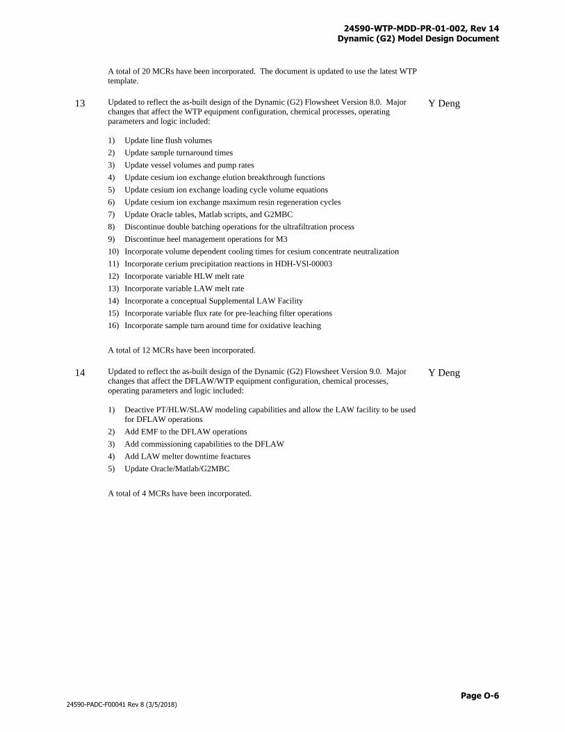
24590-WTP-MDD-PR-01-002, Rev 14 Dynamic (G2) Model Design Document
Page O-6
24590-PADC-F00041 Rev 8 (3/5/2018)
A total of 20 MCRs have been incorporated. The document is updated to use the latest WTP
template.
13 Updated to reflect the as-built design of the Dynamic (G2) Flowsheet Version 8.0. Major
changes that affect the WTP equipment configuration, chemical processes, operating
parameters and logic included:
1) Update line flush volumes
2) Update sample turnaround times
3) Update vessel volumes and pump rates
4) Update cesium ion exchange elution breakthrough functions
5) Update cesium ion exchange loading cycle volume equations
6) Update cesium ion exchange maximum resin regeneration cycles
7) Update Oracle tables, Matlab scripts, and G2MBC
8) Discontinue double batching operations for the ultrafiltration process
9) Discontinue heel management operations for M3
10) Incorporate volume dependent cooling times for cesium concentrate neutralization
11) Incorporate cerium precipitation reactions in HDH-VSl-00003
12) Incorporate variable HLW melt rate
13) Incorporate variable LAW melt rate
14) Incorporate a conceptual Supplemental LAW Facility
15) Incorporate variable flux rate for pre-leaching filter operations
16) Incorporate sample turn around time for oxidative leaching
A total of 12 MCRs have been incorporated.
Y Deng
14 Updated to reflect the as-built design of the Dynamic (G2) Flowsheet Version 9.0. Major
changes that affect the DFLAW/WTP equipment configuration, chemical processes,
operating parameters and logic included:
1) Deactive PT/HLW/SLAW modeling capabilities and allow the LAW facility to be used
for DFLAW operations
2) Add EMF to the DFLAW operations
3) Add commissioning capabilities to the DFLAW
4) Add LAW melter downtime feactures
5) Update Oracle/Matlab/G2MBC
A total of 4 MCRs have been incorporated.
Y Deng

24590-WTP-MDD-PR-01-002, Rev 14 Dynamic (G2) Model Design Document
Page P-i
24590-PADC-F00041 Rev 8 (3/5/2018)
Appendix P
DFLAW Commissioning Logic
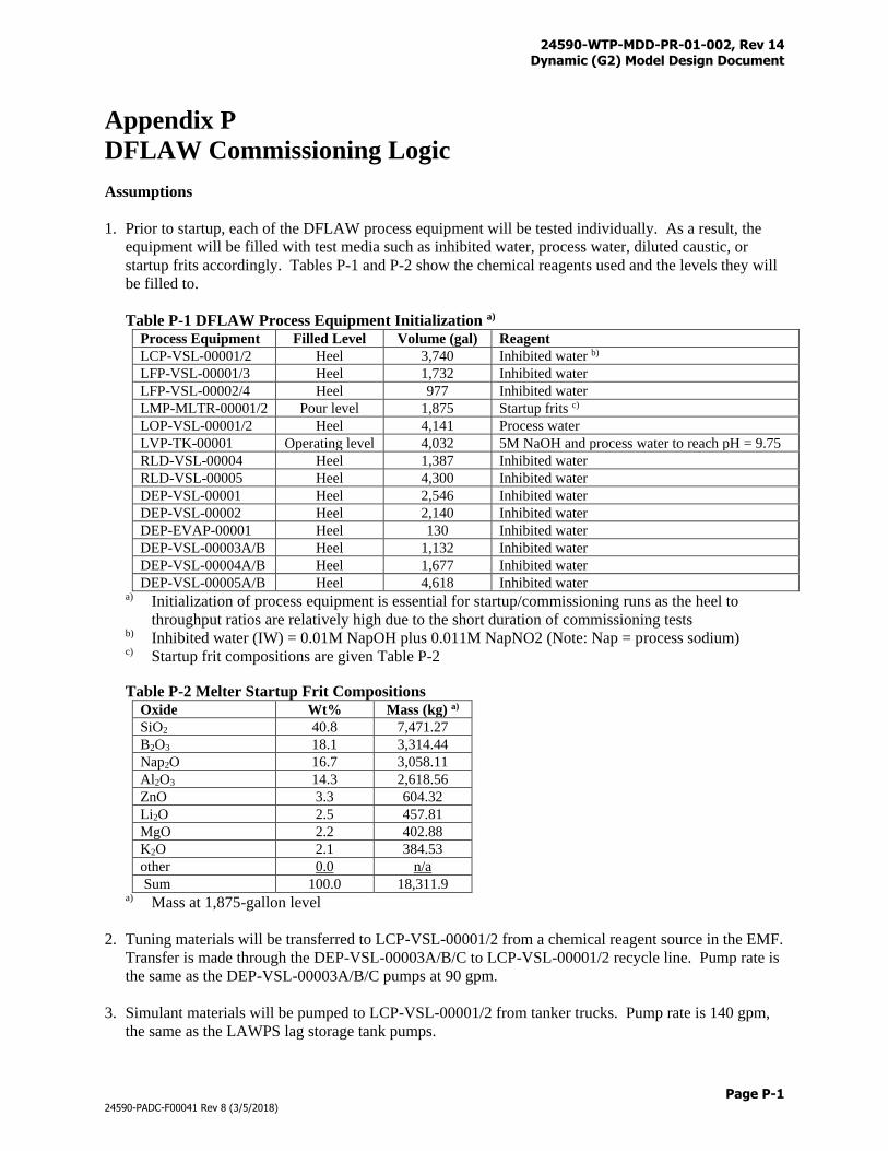
24590-WTP-MDD-PR-01-002, Rev 14 Dynamic (G2) Model Design Document
Page P-1
24590-PADC-F00041 Rev 8 (3/5/2018)
Appendix P
DFLAW Commissioning Logic
Assumptions
1. Prior to startup, each of the DFLAW process equipment will be tested individually. As a result, the
equipment will be filled with test media such as inhibited water, process water, diluted caustic, or
startup frits accordingly. Tables P-1 and P-2 show the chemical reagents used and the levels they will
be filled to.
Table P-1 DFLAW Process Equipment Initialization a) Process Equipment Filled Level Volume (gal) Reagent
LCP-VSL-00001/2 Heel 3,740 Inhibited water b)
LFP-VSL-00001/3 Heel 1,732 Inhibited water
LFP-VSL-00002/4 Heel 977 Inhibited water
LMP-MLTR-00001/2 Pour level 1,875 Startup frits c)
LOP-VSL-00001/2 Heel 4,141 Process water
LVP-TK-00001 Operating level 4,032 5M NaOH and process water to reach pH = 9.75
RLD-VSL-00004 Heel 1,387 Inhibited water
RLD-VSL-00005 Heel 4,300 Inhibited water
DEP-VSL-00001 Heel 2,546 Inhibited water
DEP-VSL-00002 Heel 2,140 Inhibited water
DEP-EVAP-00001 Heel 130 Inhibited water
DEP-VSL-00003A/B Heel 1,132 Inhibited water
DEP-VSL-00004A/B Heel 1,677 Inhibited water
DEP-VSL-00005A/B Heel 4,618 Inhibited water a) Initialization of process equipment is essential for startup/commissioning runs as the heel to
throughput ratios are relatively high due to the short duration of commissioning tests b) Inhibited water (IW) = 0.01M NapOH plus 0.011M NapNO2 (Note: Nap = process sodium) c) Startup frit compositions are given Table P-2
Table P-2 Melter Startup Frit Compositions
Oxide Wt% Mass (kg) a)
SiO2 40.8 7,471.27
B2O3 18.1 3,314.44
Nap2O 16.7 3,058.11
Al2O3 14.3 2,618.56
ZnO 3.3 604.32
Li2O 2.5 457.81
MgO 2.2 402.88
K2O 2.1 384.53
other 0.0 n/a
Sum 100.0 18,311.9 a) Mass at 1,875-gallon level
2. Tuning materials will be transferred to LCP-VSL-00001/2 from a chemical reagent source in the EMF.
Transfer is made through the DEP-VSL-00003A/B/C to LCP-VSL-00001/2 recycle line. Pump rate is
the same as the DEP-VSL-00003A/B/C pumps at 90 gpm.
3. Simulant materials will be pumped to LCP-VSL-00001/2 from tanker trucks. Pump rate is 140 gpm,
the same as the LAWPS lag storage tank pumps.
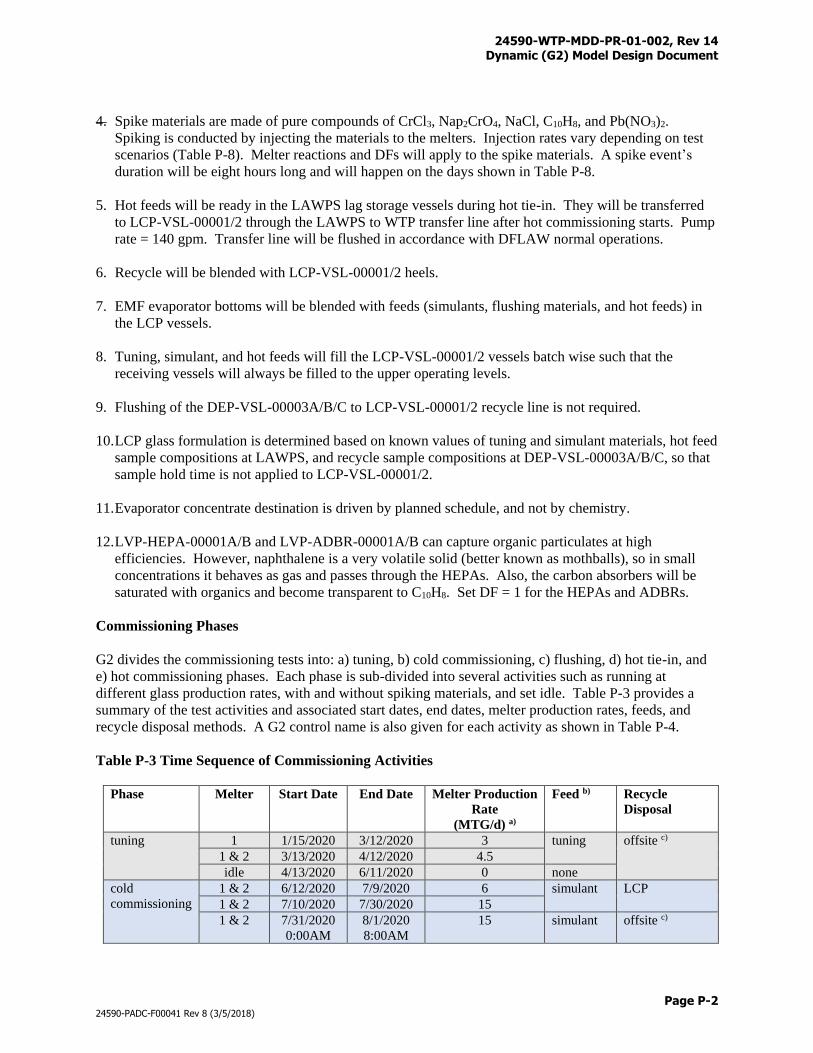
24590-WTP-MDD-PR-01-002, Rev 14 Dynamic (G2) Model Design Document
Page P-2
24590-PADC-F00041 Rev 8 (3/5/2018)
4. Spike materials are made of pure compounds of CrCl3, Nap2CrO4, NaCl, C10H8, and Pb(NO3)2.
Spiking is conducted by injecting the materials to the melters. Injection rates vary depending on test
scenarios (Table P-8). Melter reactions and DFs will apply to the spike materials. A spike event’s
duration will be eight hours long and will happen on the days shown in Table P-8.
5. Hot feeds will be ready in the LAWPS lag storage vessels during hot tie-in. They will be transferred
to LCP-VSL-00001/2 through the LAWPS to WTP transfer line after hot commissioning starts. Pump
rate = 140 gpm. Transfer line will be flushed in accordance with DFLAW normal operations.
6. Recycle will be blended with LCP-VSL-00001/2 heels.
7. EMF evaporator bottoms will be blended with feeds (simulants, flushing materials, and hot feeds) in
the LCP vessels.
8. Tuning, simulant, and hot feeds will fill the LCP-VSL-00001/2 vessels batch wise such that the
receiving vessels will always be filled to the upper operating levels.
9. Flushing of the DEP-VSL-00003A/B/C to LCP-VSL-00001/2 recycle line is not required.
10. LCP glass formulation is determined based on known values of tuning and simulant materials, hot feed
sample compositions at LAWPS, and recycle sample compositions at DEP-VSL-00003A/B/C, so that
sample hold time is not applied to LCP-VSL-00001/2.
11. Evaporator concentrate destination is driven by planned schedule, and not by chemistry.
12. LVP-HEPA-00001A/B and LVP-ADBR-00001A/B can capture organic particulates at high
efficiencies. However, naphthalene is a very volatile solid (better known as mothballs), so in small
concentrations it behaves as gas and passes through the HEPAs. Also, the carbon absorbers will be
saturated with organics and become transparent to C10H8. Set DF = 1 for the HEPAs and ADBRs.
Commissioning Phases
G2 divides the commissioning tests into: a) tuning, b) cold commissioning, c) flushing, d) hot tie-in, and
e) hot commissioning phases. Each phase is sub-divided into several activities such as running at
different glass production rates, with and without spiking materials, and set idle. Table P-3 provides a
summary of the test activities and associated start dates, end dates, melter production rates, feeds, and
recycle disposal methods. A G2 control name is also given for each activity as shown in Table P-4.
Table P-3 Time Sequence of Commissioning Activities
Phase Melter Start Date End Date Melter Production
Rate
(MTG/d) a)
Feed b) Recycle
Disposal
tuning 1 1/15/2020 3/12/2020 3 tuning offsite c)
1 & 2 3/13/2020 4/12/2020 4.5
idle 4/13/2020 6/11/2020 0 none
cold
commissioning
1 & 2 6/12/2020 7/9/2020 6 simulant LCP
1 & 2 7/10/2020 7/30/2020 15
1 & 2 7/31/2020
0:00AM
8/1/2020
8:00AM
15 simulant offsite c)
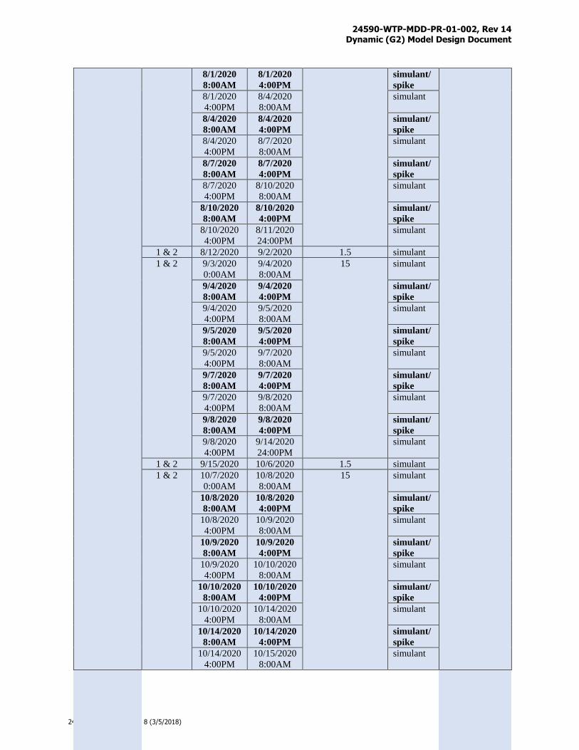
24590-WTP-MDD-PR-01-002, Rev 14 Dynamic (G2) Model Design Document
Page P-3
24590-PADC-F00041 Rev 8 (3/5/2018)
8/1/2020
8:00AM
8/1/2020
4:00PM
simulant/
spike
8/1/2020
4:00PM
8/4/2020
8:00AM
simulant
8/4/2020
8:00AM
8/4/2020
4:00PM
simulant/
spike
8/4/2020
4:00PM
8/7/2020
8:00AM
simulant
8/7/2020
8:00AM
8/7/2020
4:00PM
simulant/
spike
8/7/2020
4:00PM
8/10/2020
8:00AM
simulant
8/10/2020
8:00AM
8/10/2020
4:00PM
simulant/
spike
8/10/2020
4:00PM
8/11/2020
24:00PM
simulant
1 & 2 8/12/2020 9/2/2020 1.5 simulant
1 & 2 9/3/2020
0:00AM
9/4/2020
8:00AM
15 simulant
9/4/2020
8:00AM
9/4/2020
4:00PM
simulant/
spike
9/4/2020
4:00PM
9/5/2020
8:00AM
simulant
9/5/2020
8:00AM
9/5/2020
4:00PM
simulant/
spike
9/5/2020
4:00PM
9/7/2020
8:00AM
simulant
9/7/2020
8:00AM
9/7/2020
4:00PM
simulant/
spike
9/7/2020
4:00PM
9/8/2020
8:00AM
simulant
9/8/2020
8:00AM
9/8/2020
4:00PM
simulant/
spike
9/8/2020
4:00PM
9/14/2020
24:00PM
simulant
1 & 2 9/15/2020 10/6/2020 1.5 simulant
1 & 2 10/7/2020
0:00AM
10/8/2020
8:00AM
15 simulant
10/8/2020
8:00AM
10/8/2020
4:00PM
simulant/
spike
10/8/2020
4:00PM
10/9/2020
8:00AM
simulant
10/9/2020
8:00AM
10/9/2020
4:00PM
simulant/
spike
10/9/2020
4:00PM
10/10/2020
8:00AM
simulant
10/10/2020
8:00AM
10/10/2020
4:00PM
simulant/
spike
10/10/2020
4:00PM
10/14/2020
8:00AM
simulant
10/14/2020
8:00AM
10/14/2020
4:00PM
simulant/
spike
10/14/2020
4:00PM
10/15/2020
8:00AM
simulant
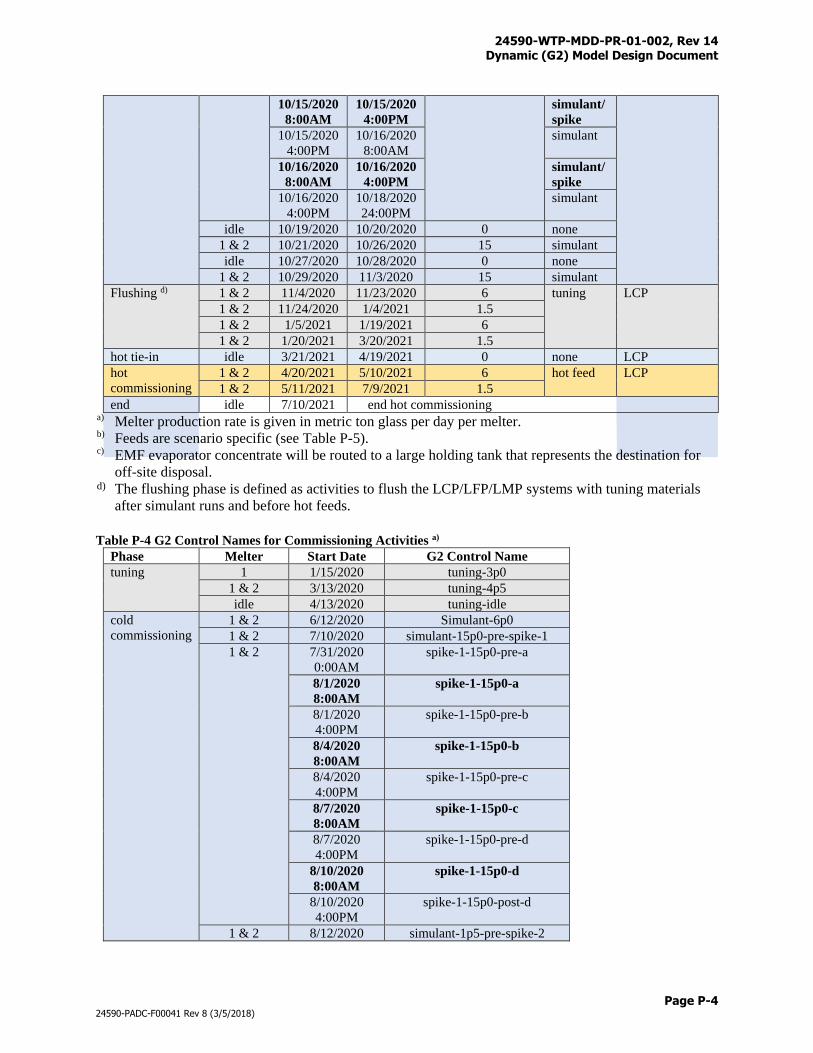
24590-WTP-MDD-PR-01-002, Rev 14 Dynamic (G2) Model Design Document
Page P-4
24590-PADC-F00041 Rev 8 (3/5/2018)
10/15/2020
8:00AM
10/15/2020
4:00PM
simulant/
spike
10/15/2020
4:00PM
10/16/2020
8:00AM
simulant
10/16/2020
8:00AM
10/16/2020
4:00PM
simulant/
spike
10/16/2020
4:00PM
10/18/2020
24:00PM
simulant
idle 10/19/2020 10/20/2020 0 none
1 & 2 10/21/2020 10/26/2020 15 simulant
idle 10/27/2020 10/28/2020 0 none
1 & 2 10/29/2020 11/3/2020 15 simulant
Flushing d) 1 & 2 11/4/2020 11/23/2020 6 tuning LCP
1 & 2 11/24/2020 1/4/2021 1.5
1 & 2 1/5/2021 1/19/2021 6
1 & 2 1/20/2021 3/20/2021 1.5
hot tie-in idle 3/21/2021 4/19/2021 0 none LCP
hot
commissioning
1 & 2 4/20/2021 5/10/2021 6 hot feed LCP
1 & 2 5/11/2021 7/9/2021 1.5
end idle 7/10/2021 end hot commissioning a) Melter production rate is given in metric ton glass per day per melter. b) Feeds are scenario specific (see Table P-5). c) EMF evaporator concentrate will be routed to a large holding tank that represents the destination for
off-site disposal. d) The flushing phase is defined as activities to flush the LCP/LFP/LMP systems with tuning materials
after simulant runs and before hot feeds.
Table P-4 G2 Control Names for Commissioning Activities a)
Phase Melter Start Date G2 Control Name
tuning 1 1/15/2020 tuning-3p0
1 & 2 3/13/2020 tuning-4p5
idle 4/13/2020 tuning-idle
cold
commissioning
1 & 2 6/12/2020 Simulant-6p0
1 & 2 7/10/2020 simulant-15p0-pre-spike-1
1 & 2 7/31/2020
0:00AM
spike-1-15p0-pre-a
8/1/2020
8:00AM
spike-1-15p0-a
8/1/2020
4:00PM
spike-1-15p0-pre-b
8/4/2020
8:00AM
spike-1-15p0-b
8/4/2020
4:00PM
spike-1-15p0-pre-c
8/7/2020
8:00AM
spike-1-15p0-c
8/7/2020
4:00PM
spike-1-15p0-pre-d
8/10/2020
8:00AM
spike-1-15p0-d
8/10/2020
4:00PM
spike-1-15p0-post-d
1 & 2 8/12/2020 simulant-1p5-pre-spike-2
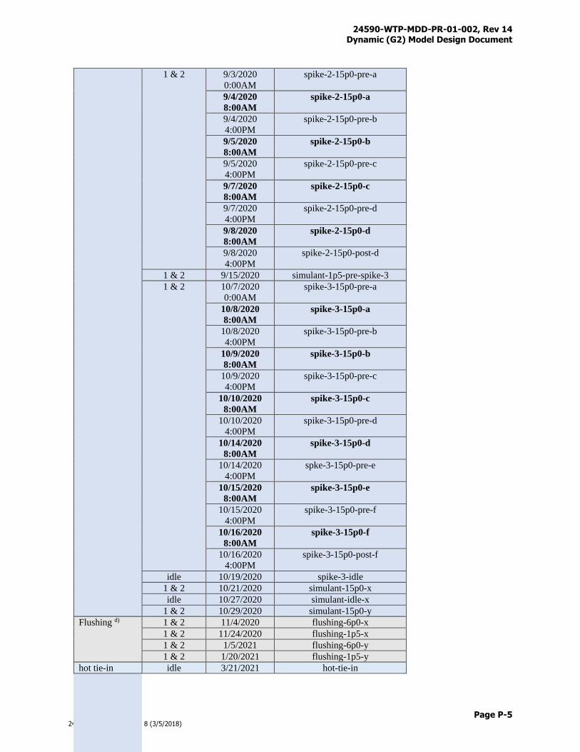
24590-WTP-MDD-PR-01-002, Rev 14 Dynamic (G2) Model Design Document
Page P-5
24590-PADC-F00041 Rev 8 (3/5/2018)
1 & 2 9/3/2020
0:00AM
spike-2-15p0-pre-a
9/4/2020
8:00AM
spike-2-15p0-a
9/4/2020
4:00PM
spike-2-15p0-pre-b
9/5/2020
8:00AM
spike-2-15p0-b
9/5/2020
4:00PM
spike-2-15p0-pre-c
9/7/2020
8:00AM
spike-2-15p0-c
9/7/2020
4:00PM
spike-2-15p0-pre-d
9/8/2020
8:00AM
spike-2-15p0-d
9/8/2020
4:00PM
spike-2-15p0-post-d
1 & 2 9/15/2020 simulant-1p5-pre-spike-3
1 & 2 10/7/2020
0:00AM
spike-3-15p0-pre-a
10/8/2020
8:00AM
spike-3-15p0-a
10/8/2020
4:00PM
spike-3-15p0-pre-b
10/9/2020
8:00AM
spike-3-15p0-b
10/9/2020
4:00PM
spike-3-15p0-pre-c
10/10/2020
8:00AM
spike-3-15p0-c
10/10/2020
4:00PM
spike-3-15p0-pre-d
10/14/2020
8:00AM
spike-3-15p0-d
10/14/2020
4:00PM
spke-3-15p0-pre-e
10/15/2020
8:00AM
spike-3-15p0-e
10/15/2020
4:00PM
spike-3-15p0-pre-f
10/16/2020
8:00AM
spike-3-15p0-f
10/16/2020
4:00PM
spike-3-15p0-post-f
idle 10/19/2020 spike-3-idle
1 & 2 10/21/2020 simulant-15p0-x
idle 10/27/2020 simulant-idle-x
1 & 2 10/29/2020 simulant-15p0-y
Flushing d) 1 & 2 11/4/2020 flushing-6p0-x
1 & 2 11/24/2020 flushing-1p5-x
1 & 2 1/5/2021 flushing-6p0-y
1 & 2 1/20/2021 flushing-1p5-y
hot tie-in idle 3/21/2021 hot-tie-in
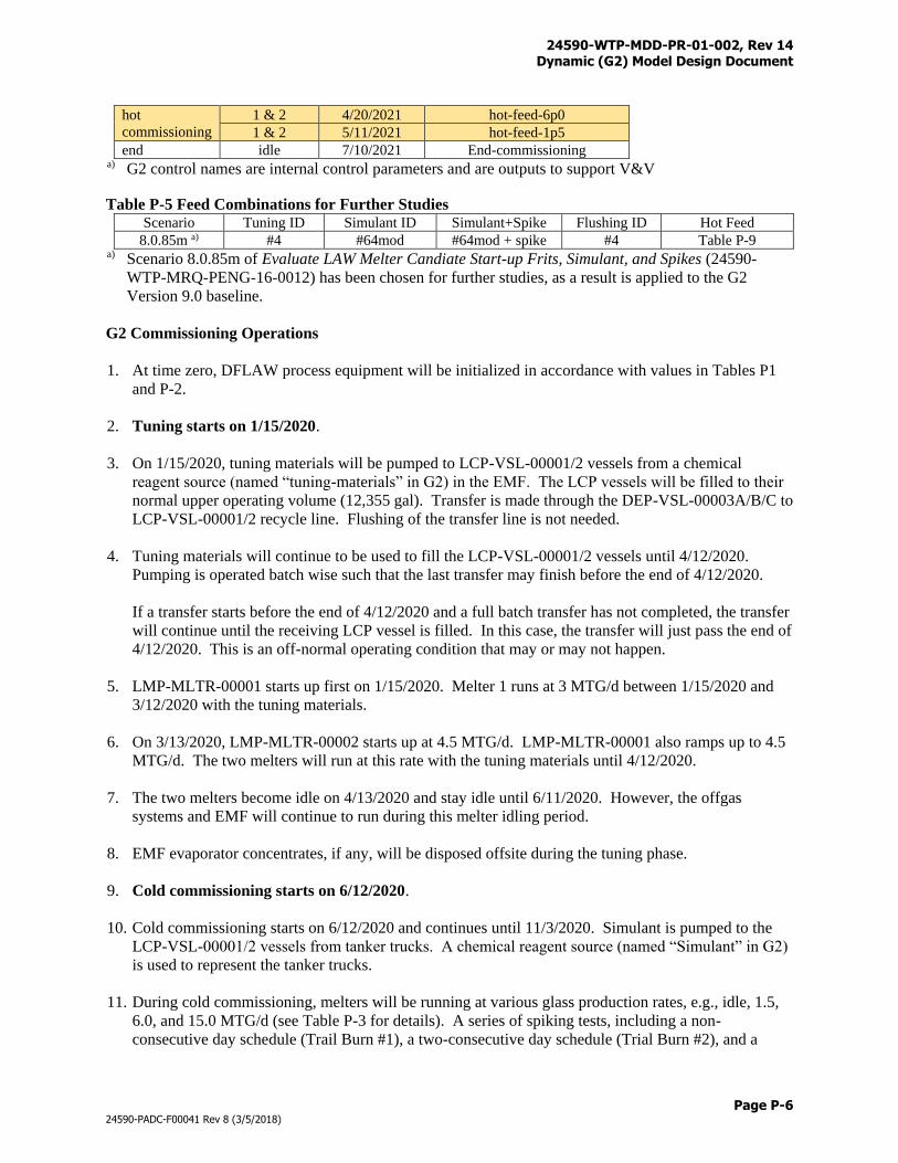
24590-WTP-MDD-PR-01-002, Rev 14 Dynamic (G2) Model Design Document
Page P-6
24590-PADC-F00041 Rev 8 (3/5/2018)
hot
commissioning
1 & 2 4/20/2021 hot-feed-6p0
1 & 2 5/11/2021 hot-feed-1p5
end idle 7/10/2021 End-commissioning a) G2 control names are internal control parameters and are outputs to support V&V
Table P-5 Feed Combinations for Further Studies Scenario Tuning ID Simulant ID Simulant+Spike Flushing ID Hot Feed
8.0.85m a) #4 #64mod #64mod + spike #4 Table P-9 a) Scenario 8.0.85m of Evaluate LAW Melter Candiate Start-up Frits, Simulant, and Spikes (24590-
WTP-MRQ-PENG-16-0012) has been chosen for further studies, as a result is applied to the G2
Version 9.0 baseline.
G2 Commissioning Operations
1. At time zero, DFLAW process equipment will be initialized in accordance with values in Tables P1
and P-2.
2. Tuning starts on 1/15/2020.
3. On 1/15/2020, tuning materials will be pumped to LCP-VSL-00001/2 vessels from a chemical
reagent source (named “tuning-materials” in G2) in the EMF. The LCP vessels will be filled to their
normal upper operating volume (12,355 gal). Transfer is made through the DEP-VSL-00003A/B/C to
LCP-VSL-00001/2 recycle line. Flushing of the transfer line is not needed.
4. Tuning materials will continue to be used to fill the LCP-VSL-00001/2 vessels until 4/12/2020.
Pumping is operated batch wise such that the last transfer may finish before the end of 4/12/2020.
If a transfer starts before the end of 4/12/2020 and a full batch transfer has not completed, the transfer
will continue until the receiving LCP vessel is filled. In this case, the transfer will just pass the end of
4/12/2020. This is an off-normal operating condition that may or may not happen.
5. LMP-MLTR-00001 starts up first on 1/15/2020. Melter 1 runs at 3 MTG/d between 1/15/2020 and
3/12/2020 with the tuning materials.
6. On 3/13/2020, LMP-MLTR-00002 starts up at 4.5 MTG/d. LMP-MLTR-00001 also ramps up to 4.5
MTG/d. The two melters will run at this rate with the tuning materials until 4/12/2020.
7. The two melters become idle on 4/13/2020 and stay idle until 6/11/2020. However, the offgas
systems and EMF will continue to run during this melter idling period.
8. EMF evaporator concentrates, if any, will be disposed offsite during the tuning phase.
9. Cold commissioning starts on 6/12/2020.
10. Cold commissioning starts on 6/12/2020 and continues until 11/3/2020. Simulant is pumped to the
LCP-VSL-00001/2 vessels from tanker trucks. A chemical reagent source (named “Simulant” in G2)
is used to represent the tanker trucks.
11. During cold commissioning, melters will be running at various glass production rates, e.g., idle, 1.5,
6.0, and 15.0 MTG/d (see Table P-3 for details). A series of spiking tests, including a non-
consecutive day schedule (Trail Burn #1), a two-consecutive day schedule (Trial Burn #2), and a
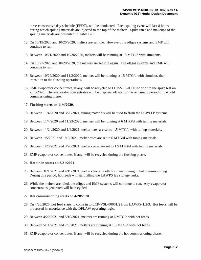
24590-WTP-MDD-PR-01-002, Rev 14 Dynamic (G2) Model Design Document
Page P-7
24590-PADC-F00041 Rev 8 (3/5/2018)
three-consecutive day schedule (EPDT), will be conducted. Each spiking event will last 8 hours
during which spiking materials are injected to the top of the melters. Spike rates and makeups of the
spiking materials are presented in Table P-8.
12. On 10/19/2020 and 10/20/2020, melters are set idle. However, the offgas systems and EMF will
continue to run.
13. Between 10/21/2020 and 10/26/2020, melters will be running at 15 MTG/d with simulants.
14. On 10/27/2020 and 10/28/2020, the melters are set idle again. The offgas systems and EMF will
continue to run.
15. Between 10/29/2020 and 11/3/2020, melters will be running at 15 MTG/d with simulant, then
transition to the flushing operations.
16. EMF evaporator concentrates, if any, will be recycled to LCP-VSL-00001/2 prior to the spike test on
7/31/2020. The evaporator concentrates will be disposed offsite for the remaining period of the cold
commissioning phase.
17. Flushing starts on 11/4/2020.
18. Between 11/4/2020 and 3/20/2021, tuning materials will be used to flush the LCP/LFP systems.
19. Between 11/4/2020 and 11/23/2020, melters will be running at 6 MTG/d with tuning materials.
20. Between 11/24/2020 and 1/4/2021, melter rates are set to 1.5 MTG/d with tuning materials.
21. Between 1/5/2021 and 1/19/2021, melter rates are set to 6 MTG/d with tuning materials.
22. Between 1/20/2021 and 3/20/2021, melters rates are set to 1.5 MTG/d with tuning materials.
23. EMF evaporator concentrates, if any, will be recycled during the flushing phase.
24. Hot tie-in starts on 3/21/2021.
25. Between 3/21/2021 and 4/19/2021, melters become idle for transitioning to hot commissioning.
During this period, hot feeds will start filling the LAWPS lag storage tanks.
26. While the melters are idled, the offgas and EMF systems will continue to run. Any evaporator
concentrates generated will be recycled.
27. Hot commissioning starts on 4/20/2020.
28. On 4/20/2020, hot feed starts to come in to LCP-VSL-00001/2 from LAWPS-1/2/3. Hot feeds will be
processed in accordance with the DFLAW operating logic.
29. Between 4/20/2021 and 5/10/2021, melters are running at 6 MTG/d with hot feeds.
30. Between 5/11/2021 and 7/9/2021, melters are running at 1.5 MTG/d with hot feeds.
31. EMF evaporator concentrates, if any, will be recycled during the hot commissioning phase.
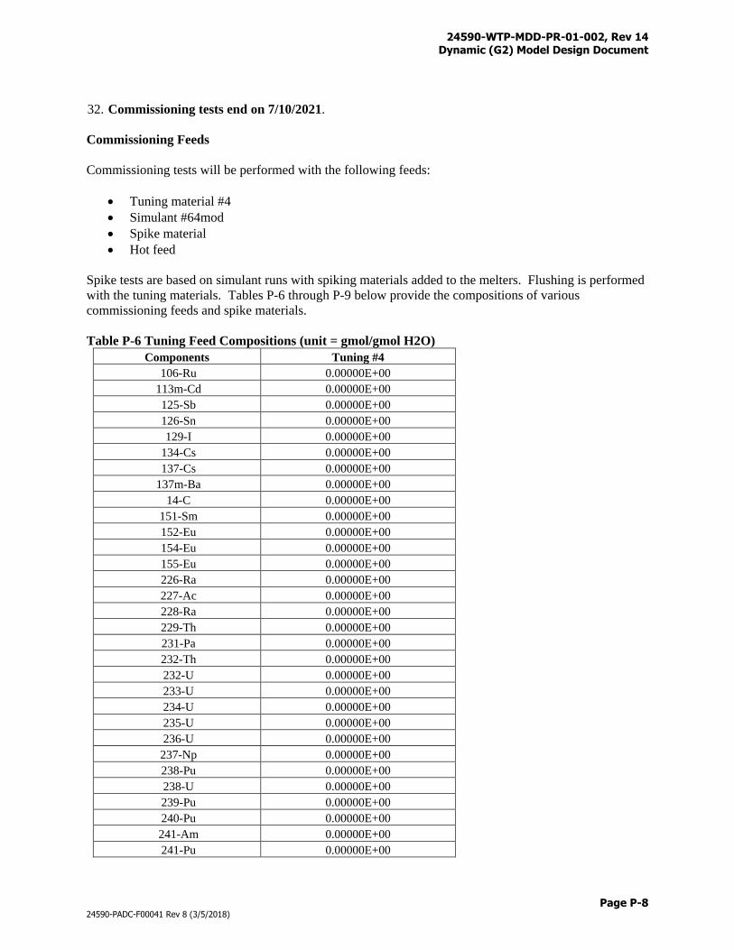
24590-WTP-MDD-PR-01-002, Rev 14 Dynamic (G2) Model Design Document
Page P-8
24590-PADC-F00041 Rev 8 (3/5/2018)
32. Commissioning tests end on 7/10/2021.
Commissioning Feeds
Commissioning tests will be performed with the following feeds:
Tuning material #4
Simulant #64mod
Spike material
Hot feed
Spike tests are based on simulant runs with spiking materials added to the melters. Flushing is performed
with the tuning materials. Tables P-6 through P-9 below provide the compositions of various
commissioning feeds and spike materials.
Table P-6 Tuning Feed Compositions (unit = gmol/gmol H2O)
Components Tuning #4
106-Ru 0.00000E+00
113m-Cd 0.00000E+00
125-Sb 0.00000E+00
126-Sn 0.00000E+00
129-I 0.00000E+00
134-Cs 0.00000E+00
137-Cs 0.00000E+00
137m-Ba 0.00000E+00
14-C 0.00000E+00
151-Sm 0.00000E+00
152-Eu 0.00000E+00
154-Eu 0.00000E+00
155-Eu 0.00000E+00
226-Ra 0.00000E+00
227-Ac 0.00000E+00
228-Ra 0.00000E+00
229-Th 0.00000E+00
231-Pa 0.00000E+00
232-Th 0.00000E+00
232-U 0.00000E+00
233-U 0.00000E+00
234-U 0.00000E+00
235-U 0.00000E+00
236-U 0.00000E+00
237-Np 0.00000E+00
238-Pu 0.00000E+00
238-U 0.00000E+00
239-Pu 0.00000E+00
240-Pu 0.00000E+00
241-Am 0.00000E+00
241-Pu 0.00000E+00
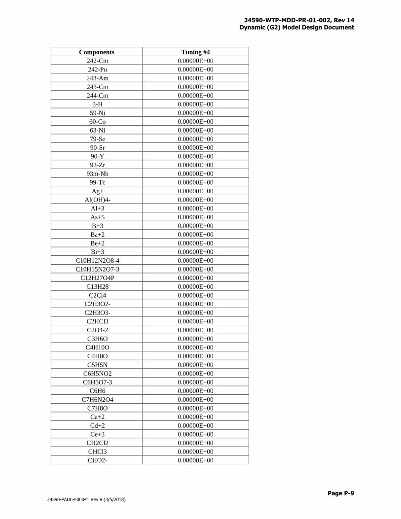
24590-WTP-MDD-PR-01-002, Rev 14 Dynamic (G2) Model Design Document
Page P-9
24590-PADC-F00041 Rev 8 (3/5/2018)
Components Tuning #4
242-Cm 0.00000E+00
242-Pu 0.00000E+00
243-Am 0.00000E+00
243-Cm 0.00000E+00
244-Cm 0.00000E+00
3-H 0.00000E+00
59-Ni 0.00000E+00
60-Co 0.00000E+00
63-Ni 0.00000E+00
79-Se 0.00000E+00
90-Sr 0.00000E+00
90-Y 0.00000E+00
93-Zr 0.00000E+00
93m-Nb 0.00000E+00
99-Tc 0.00000E+00
Ag+ 0.00000E+00
Al(OH)4- 0.00000E+00
Al+3 0.00000E+00
As+5 0.00000E+00
B+3 0.00000E+00
Ba+2 0.00000E+00
Be+2 0.00000E+00
Bi+3 0.00000E+00
C10H12N2O8-4 0.00000E+00
C10H15N2O7-3 0.00000E+00
C12H27O4P 0.00000E+00
C13H28 0.00000E+00
C2Cl4 0.00000E+00
C2H3O2- 0.00000E+00
C2H3O3- 0.00000E+00
C2HCl3 0.00000E+00
C2O4-2 0.00000E+00
C3H6O 0.00000E+00
C4H10O 0.00000E+00
C4H8O 0.00000E+00
C5H5N 0.00000E+00
C6H5NO2 0.00000E+00
C6H5O7-3 0.00000E+00
C6H6 0.00000E+00
C7H6N2O4 0.00000E+00
C7H8O 0.00000E+00
Ca+2 0.00000E+00
Cd+2 0.00000E+00
Ce+3 0.00000E+00
CH2Cl2 0.00000E+00
CHCl3 0.00000E+00
CHO2- 0.00000E+00
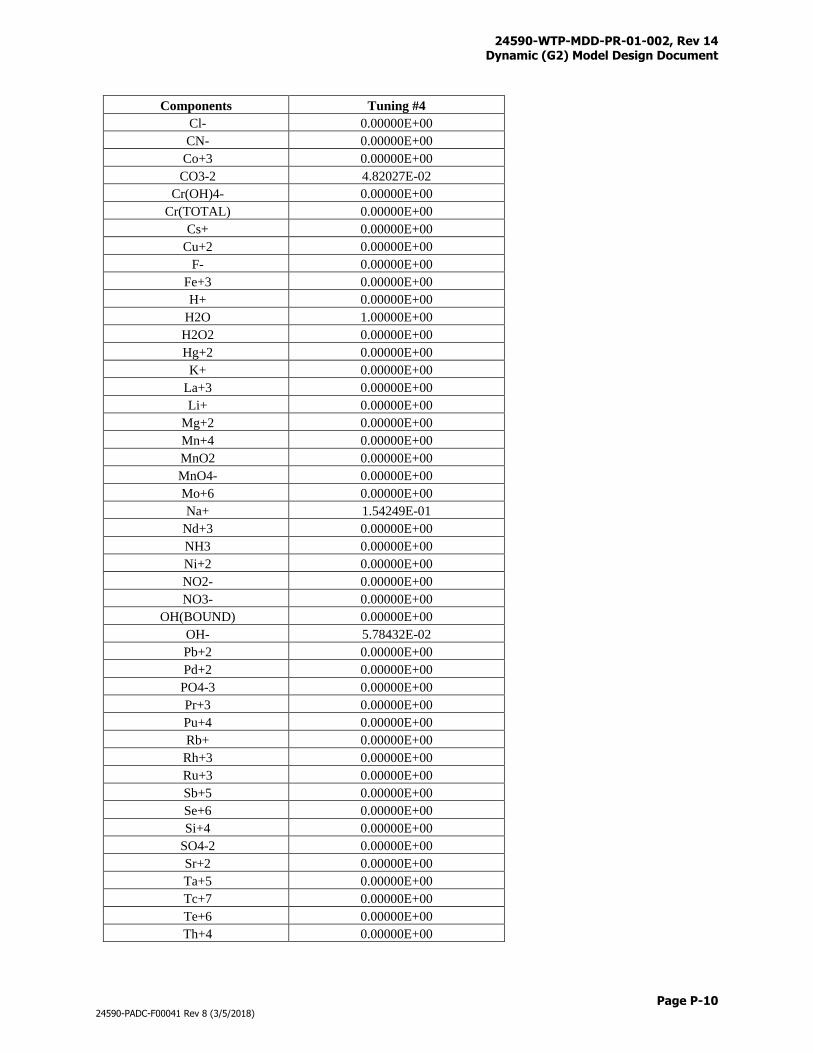
24590-WTP-MDD-PR-01-002, Rev 14 Dynamic (G2) Model Design Document
Page P-10
24590-PADC-F00041 Rev 8 (3/5/2018)
Components Tuning #4
Cl- 0.00000E+00
CN- 0.00000E+00
Co+3 0.00000E+00
CO3-2 4.82027E-02
Cr(OH)4- 0.00000E+00
Cr(TOTAL) 0.00000E+00
Cs+ 0.00000E+00
Cu+2 0.00000E+00
F- 0.00000E+00
Fe+3 0.00000E+00
H+ 0.00000E+00
H2O 1.00000E+00
H2O2 0.00000E+00
Hg+2 0.00000E+00
K+ 0.00000E+00
La+3 0.00000E+00
Li+ 0.00000E+00
Mg+2 0.00000E+00
Mn+4 0.00000E+00
MnO2 0.00000E+00
MnO4- 0.00000E+00
Mo+6 0.00000E+00
Na+ 1.54249E-01
Nd+3 0.00000E+00
NH3 0.00000E+00
Ni+2 0.00000E+00
NO2- 0.00000E+00
NO3- 0.00000E+00
OH(BOUND) 0.00000E+00
OH- 5.78432E-02
Pb+2 0.00000E+00
Pd+2 0.00000E+00
PO4-3 0.00000E+00
Pr+3 0.00000E+00
Pu+4 0.00000E+00
Rb+ 0.00000E+00
Rh+3 0.00000E+00
Ru+3 0.00000E+00
Sb+5 0.00000E+00
Se+6 0.00000E+00
Si+4 0.00000E+00
SO4-2 0.00000E+00
Sr+2 0.00000E+00
Ta+5 0.00000E+00
Tc+7 0.00000E+00
Te+6 0.00000E+00
Th+4 0.00000E+00
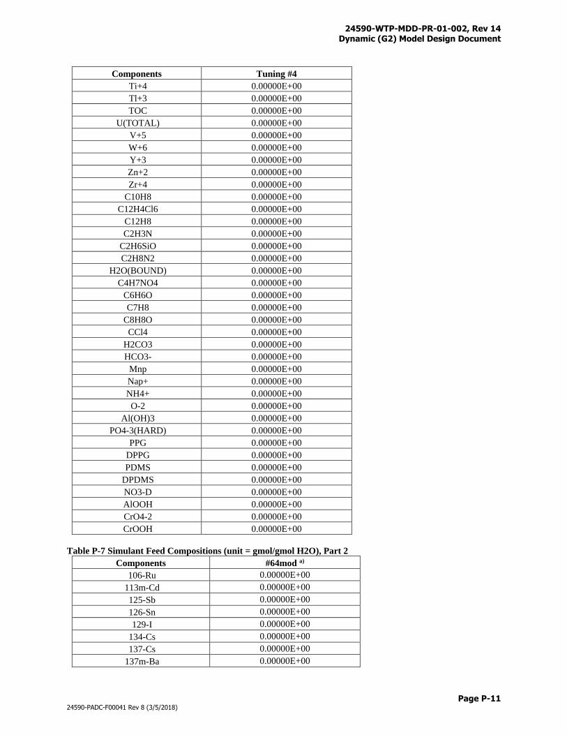
24590-WTP-MDD-PR-01-002, Rev 14 Dynamic (G2) Model Design Document
Page P-11
24590-PADC-F00041 Rev 8 (3/5/2018)
Components Tuning #4
Ti+4 0.00000E+00
Tl+3 0.00000E+00
TOC 0.00000E+00
U(TOTAL) 0.00000E+00
V+5 0.00000E+00
W+6 0.00000E+00
Y+3 0.00000E+00
Zn+2 0.00000E+00
Zr+4 0.00000E+00
C10H8 0.00000E+00
C12H4Cl6 0.00000E+00
C12H8 0.00000E+00
C2H3N 0.00000E+00
C2H6SiO 0.00000E+00
C2H8N2 0.00000E+00
H2O(BOUND) 0.00000E+00
C4H7NO4 0.00000E+00
C6H6O 0.00000E+00
C7H8 0.00000E+00
C8H8O 0.00000E+00
CCl4 0.00000E+00
H2CO3 0.00000E+00
HCO3- 0.00000E+00
Mnp 0.00000E+00
Nap+ 0.00000E+00
NH4+ 0.00000E+00
O-2 0.00000E+00
Al(OH)3 0.00000E+00
PO4-3(HARD) 0.00000E+00
PPG 0.00000E+00
DPPG 0.00000E+00
PDMS 0.00000E+00
DPDMS 0.00000E+00
NO3-D 0.00000E+00
AlOOH 0.00000E+00
CrO4-2 0.00000E+00
CrOOH 0.00000E+00
Table P-7 Simulant Feed Compositions (unit = gmol/gmol H2O), Part 2
Components #64mod a)
106-Ru 0.00000E+00
113m-Cd 0.00000E+00
125-Sb 0.00000E+00
126-Sn 0.00000E+00
129-I 0.00000E+00
134-Cs 0.00000E+00
137-Cs 0.00000E+00
137m-Ba 0.00000E+00

24590-WTP-MDD-PR-01-002, Rev 14 Dynamic (G2) Model Design Document
Page P-12
24590-PADC-F00041 Rev 8 (3/5/2018)
Components #64mod a)
14-C 0.00000E+00
151-Sm 0.00000E+00
152-Eu 0.00000E+00
154-Eu 0.00000E+00
155-Eu 0.00000E+00
226-Ra 0.00000E+00
227-Ac 0.00000E+00
228-Ra 0.00000E+00
229-Th 0.00000E+00
231-Pa 0.00000E+00
232-Th 0.00000E+00
232-U 0.00000E+00
233-U 0.00000E+00
234-U 0.00000E+00
235-U 0.00000E+00
236-U 0.00000E+00
237-Np 0.00000E+00
238-Pu 0.00000E+00
238-U 0.00000E+00
239-Pu 0.00000E+00
240-Pu 0.00000E+00
241-Am 0.00000E+00
241-Pu 0.00000E+00
242-Cm 0.00000E+00
242-Pu 0.00000E+00
243-Am 0.00000E+00
243-Cm 0.00000E+00
244-Cm 0.00000E+00
3-H 0.00000E+00
59-Ni 0.00000E+00
60-Co 0.00000E+00
63-Ni 0.00000E+00
79-Se 0.00000E+00
90-Sr 0.00000E+00
90-Y 0.00000E+00
93-Zr 0.00000E+00
93m-Nb 0.00000E+00
99-Tc 0.00000E+00
Ag+ 0.00000E+00
Al(OH)4- 2.31471E-02
Al+3 0.00000E+00
As+5 0.00000E+00
B+3 0.00000E+00
Ba+2 0.00000E+00
Be+2 0.00000E+00
Bi+3 0.00000E+00
C10H12N2O8-4 0.00000E+00
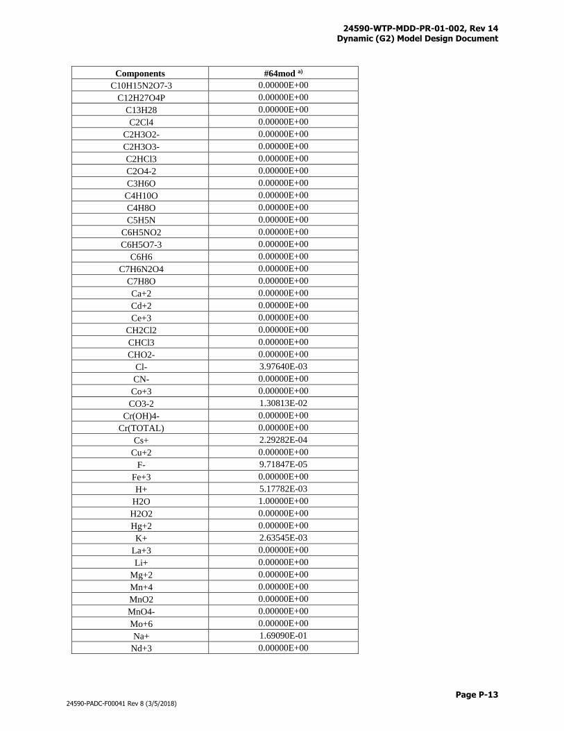
24590-WTP-MDD-PR-01-002, Rev 14 Dynamic (G2) Model Design Document
Page P-13
24590-PADC-F00041 Rev 8 (3/5/2018)
Components #64mod a)
C10H15N2O7-3 0.00000E+00
C12H27O4P 0.00000E+00
C13H28 0.00000E+00
C2Cl4 0.00000E+00
C2H3O2- 0.00000E+00
C2H3O3- 0.00000E+00
C2HCl3 0.00000E+00
C2O4-2 0.00000E+00
C3H6O 0.00000E+00
C4H10O 0.00000E+00
C4H8O 0.00000E+00
C5H5N 0.00000E+00
C6H5NO2 0.00000E+00
C6H5O7-3 0.00000E+00
C6H6 0.00000E+00
C7H6N2O4 0.00000E+00
C7H8O 0.00000E+00
Ca+2 0.00000E+00
Cd+2 0.00000E+00
Ce+3 0.00000E+00
CH2Cl2 0.00000E+00
CHCl3 0.00000E+00
CHO2- 0.00000E+00
Cl- 3.97640E-03
CN- 0.00000E+00
Co+3 0.00000E+00
CO3-2 1.30813E-02
Cr(OH)4- 0.00000E+00
Cr(TOTAL) 0.00000E+00
Cs+ 2.29282E-04
Cu+2 0.00000E+00
F- 9.71847E-05
Fe+3 0.00000E+00
H+ 5.17782E-03
H2O 1.00000E+00
H2O2 0.00000E+00
Hg+2 0.00000E+00
K+ 2.63545E-03
La+3 0.00000E+00
Li+ 0.00000E+00
Mg+2 0.00000E+00
Mn+4 0.00000E+00
MnO2 0.00000E+00
MnO4- 0.00000E+00
Mo+6 0.00000E+00
Na+ 1.69090E-01
Nd+3 0.00000E+00
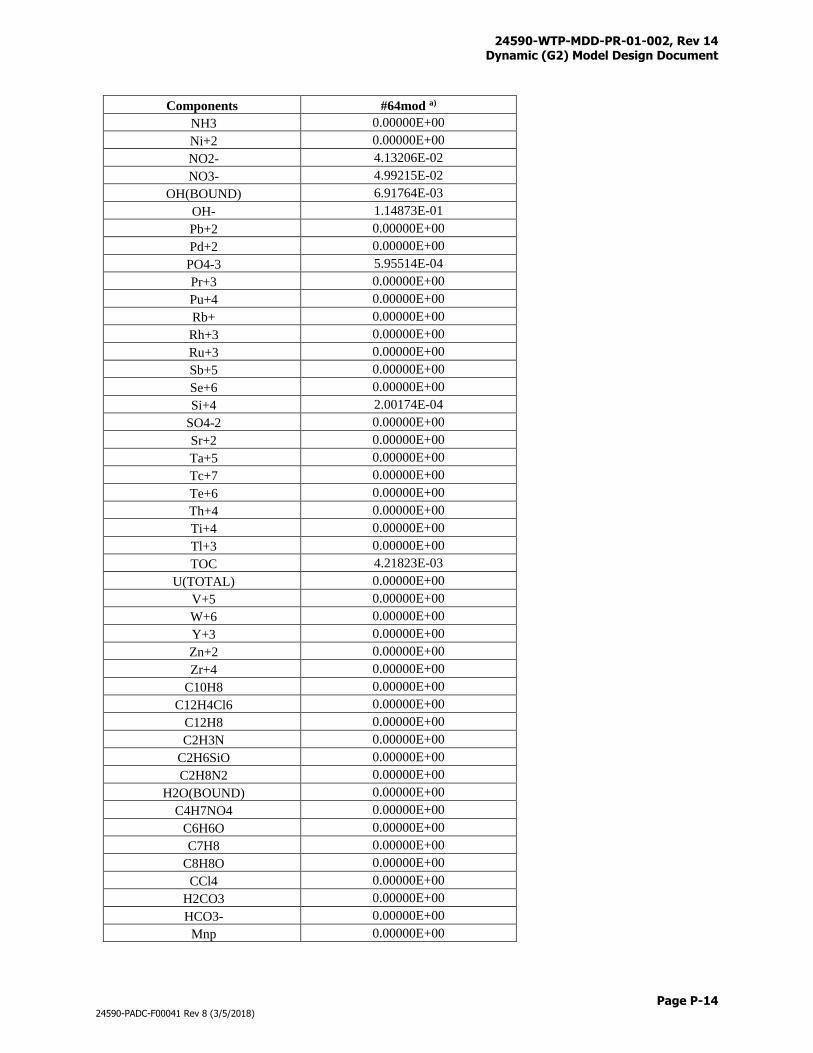
24590-WTP-MDD-PR-01-002, Rev 14 Dynamic (G2) Model Design Document
Page P-14
24590-PADC-F00041 Rev 8 (3/5/2018)
Components #64mod a)
NH3 0.00000E+00
Ni+2 0.00000E+00
NO2- 4.13206E-02
NO3- 4.99215E-02
OH(BOUND) 6.91764E-03
OH- 1.14873E-01
Pb+2 0.00000E+00
Pd+2 0.00000E+00
PO4-3 5.95514E-04
Pr+3 0.00000E+00
Pu+4 0.00000E+00
Rb+ 0.00000E+00
Rh+3 0.00000E+00
Ru+3 0.00000E+00
Sb+5 0.00000E+00
Se+6 0.00000E+00
Si+4 2.00174E-04
SO4-2 0.00000E+00
Sr+2 0.00000E+00
Ta+5 0.00000E+00
Tc+7 0.00000E+00
Te+6 0.00000E+00
Th+4 0.00000E+00
Ti+4 0.00000E+00
Tl+3 0.00000E+00
TOC 4.21823E-03
U(TOTAL) 0.00000E+00
V+5 0.00000E+00
W+6 0.00000E+00
Y+3 0.00000E+00
Zn+2 0.00000E+00
Zr+4 0.00000E+00
C10H8 0.00000E+00
C12H4Cl6 0.00000E+00
C12H8 0.00000E+00
C2H3N 0.00000E+00
C2H6SiO 0.00000E+00
C2H8N2 0.00000E+00
H2O(BOUND) 0.00000E+00
C4H7NO4 0.00000E+00
C6H6O 0.00000E+00
C7H8 0.00000E+00
C8H8O 0.00000E+00
CCl4 0.00000E+00
H2CO3 0.00000E+00
HCO3- 0.00000E+00
Mnp 0.00000E+00
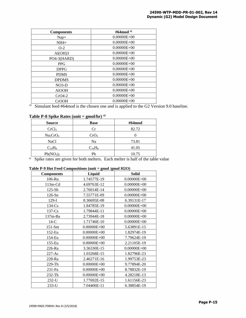
24590-WTP-MDD-PR-01-002, Rev 14 Dynamic (G2) Model Design Document
Page P-15
24590-PADC-F00041 Rev 8 (3/5/2018)
Components #64mod a)
Nap+ 0.00000E+00
NH4+ 0.00000E+00
O-2 0.00000E+00
Al(OH)3 0.00000E+00
PO4-3(HARD) 0.00000E+00
PPG 0.00000E+00
DPPG 0.00000E+00
PDMS 0.00000E+00
DPDMS 0.00000E+00
NO3-D 0.00000E+00
AlOOH 0.00000E+00
CrO4-2 0.00000E+00
CrOOH 0.00000E+00 a) Simulant feed #64mod is the chosen one and is applied to the G2 Version 9.0 baseline.
Table P-8 Spike Rates (unit = gmol/hr) a)
Source Base #64mod
CrCl3 Cr 82.72
Na2CrO4 CrO4 0
NaCl Na 73.81
C10H8 C10H8 41.05
Pb(NO3)2 Pb 10.75 a) Spike rates are given for both melters. Each melter is half of the table value
Table P-9 Hot Feed Compositions (unit = gmol /gmol H2O)
Components Liquid Solid
106-Ru 1.74577E-19 0.00000E+00
113m-Cd 4.69763E-12 0.00000E+00
125-Sb 2.76014E-14 0.00000E+00
126-Sn 7.55771E-09 0.00000E+00
129-I 8.36695E-08 6.39131E-17
134-Cs 1.84785E-19 0.00000E+00
137-Cs 1.79844E-11 0.00000E+00
137m-Ba 2.73944E-18 0.00000E+00
14-C 1.71746E-10 0.00000E+00
151-Sm 0.00000E+00 5.63891E-15
152-Eu 0.00000E+00 1.82974E-19
154-Eu 0.00000E+00 7.79624E-19
155-Eu 0.00000E+00 2.21105E-19
226-Ra 3.36330E-15 0.00000E+00
227-Ac 1.03268E-15 1.82796E-23
228-Ra 2.46271E-16 1.99753E-23
229-Th 0.00000E+00 9.77894E-20
231-Pa 0.00000E+00 8.78832E-19
232-Th 0.00000E+00 4.28218E-13
232-U 1.77692E-15 1.61156E-23
233-U 7.04406E-11 6.38854E-19
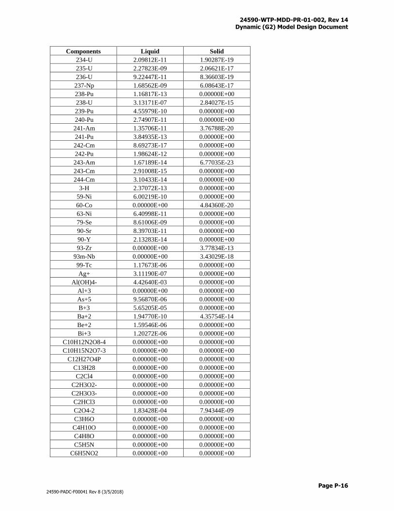
24590-WTP-MDD-PR-01-002, Rev 14 Dynamic (G2) Model Design Document
Page P-16
24590-PADC-F00041 Rev 8 (3/5/2018)
Components Liquid Solid
234-U 2.09812E-11 1.90287E-19
235-U 2.27823E-09 2.06621E-17
236-U 9.22447E-11 8.36603E-19
237-Np 1.68562E-09 6.08643E-17
238-Pu 1.16817E-13 0.00000E+00
238-U 3.13171E-07 2.84027E-15
239-Pu 4.55979E-10 0.00000E+00
240-Pu 2.74907E-11 0.00000E+00
241-Am 1.35706E-11 3.76788E-20
241-Pu 3.84935E-13 0.00000E+00
242-Cm 8.69273E-17 0.00000E+00
242-Pu 1.98624E-12 0.00000E+00
243-Am 1.67189E-14 6.77035E-23
243-Cm 2.91008E-15 0.00000E+00
244-Cm 3.10433E-14 0.00000E+00
3-H 2.37072E-13 0.00000E+00
59-Ni 6.00219E-10 0.00000E+00
60-Co 0.00000E+00 4.84360E-20
63-Ni 6.40998E-11 0.00000E+00
79-Se 8.61006E-09 0.00000E+00
90-Sr 8.39703E-11 0.00000E+00
90-Y 2.13283E-14 0.00000E+00
93-Zr 0.00000E+00 3.77834E-13
93m-Nb 0.00000E+00 3.43029E-18
99-Tc 1.17673E-06 0.00000E+00
Ag+ 3.11190E-07 0.00000E+00
Al(OH)4- 4.42640E-03 0.00000E+00
Al+3 0.00000E+00 0.00000E+00
As+5 9.56870E-06 0.00000E+00
B+3 5.65205E-05 0.00000E+00
Ba+2 1.94770E-10 4.35754E-14
Be+2 1.59546E-06 0.00000E+00
Bi+3 1.20272E-06 0.00000E+00
C10H12N2O8-4 0.00000E+00 0.00000E+00
C10H15N2O7-3 0.00000E+00 0.00000E+00
C12H27O4P 0.00000E+00 0.00000E+00
C13H28 0.00000E+00 0.00000E+00
C2Cl4 0.00000E+00 0.00000E+00
C2H3O2- 0.00000E+00 0.00000E+00
C2H3O3- 0.00000E+00 0.00000E+00
C2HCl3 0.00000E+00 0.00000E+00
C2O4-2 1.83428E-04 7.94344E-09
C3H6O 0.00000E+00 0.00000E+00
C4H10O 0.00000E+00 0.00000E+00
C4H8O 0.00000E+00 0.00000E+00
C5H5N 0.00000E+00 0.00000E+00
C6H5NO2 0.00000E+00 0.00000E+00
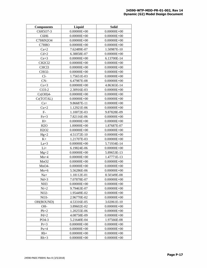
24590-WTP-MDD-PR-01-002, Rev 14 Dynamic (G2) Model Design Document
Page P-17
24590-PADC-F00041 Rev 8 (3/5/2018)
Components Liquid Solid
C6H5O7-3 0.00000E+00 0.00000E+00
C6H6 0.00000E+00 0.00000E+00
C7H6N2O4 0.00000E+00 0.00000E+00
C7H8O 0.00000E+00 0.00000E+00
Ca+2 7.62489E-07 1.50987E-10
Cd+2 6.38858E-07 0.00000E+00
Ce+3 0.00000E+00 6.13700E-14
CH2Cl2 0.00000E+00 0.00000E+00
CHCl3 0.00000E+00 0.00000E+00
CHO2- 0.00000E+00 0.00000E+00
Cl- 1.75651E-03 0.00000E+00
CN- 6.47987E-08 0.00000E+00
Co+3 0.00000E+00 4.86365E-14
CO3-2 2.30916E-03 0.00000E+00
Cr(OH)4- 0.00000E+00 0.00000E+00
Cr(TOTAL) 0.00000E+00 0.00000E+00
Cs+ 9.86687E-11 0.00000E+00
Cu+2 1.12921E-06 0.00000E+00
F- 1.10072E-03 9.87828E-09
Fe+3 7.82116E-06 0.00000E+00
H+ 0.00000E+00 0.00000E+00
H2O 1.00000E+00 1.87687E-07
H2O2 0.00000E+00 0.00000E+00
Hg+2 4.51372E-10 0.00000E+00
K+ 1.21707E-03 0.00000E+00
La+3 0.00000E+00 5.71934E-14
Li+ 6.19824E-06 0.00000E+00
Mg+2 0.00000E+00 5.89653E-13
Mn+4 0.00000E+00 1.47771E-13
MnO2 0.00000E+00 0.00000E+00
MnO4- 0.00000E+00 0.00000E+00
Mo+6 5.56286E-06 0.00000E+00
Na+ 1.18112E-01 8.50349E-08
Nd+3 7.07878E-07 0.00000E+00
NH3 0.00000E+00 0.00000E+00
Ni+2 9.79463E-07 0.00000E+00
NO2- 1.95449E-02 0.00000E+00
NO3- 2.96770E-02 0.00000E+00
OH(BOUND) 4.53316E-05 3.02061E-10
OH- 3.89602E-02 0.00000E+00
Pb+2 1.20255E-06 0.00000E+00
Pd+2 4.08758E-09 0.00000E+00
PO4-3 5.21640E-04 1.97566E-08
Pr+3 0.00000E+00 0.00000E+00
Pu+4 0.00000E+00 0.00000E+00
Rb+ 0.00000E+00 0.00000E+00
Rh+3 0.00000E+00 0.00000E+00
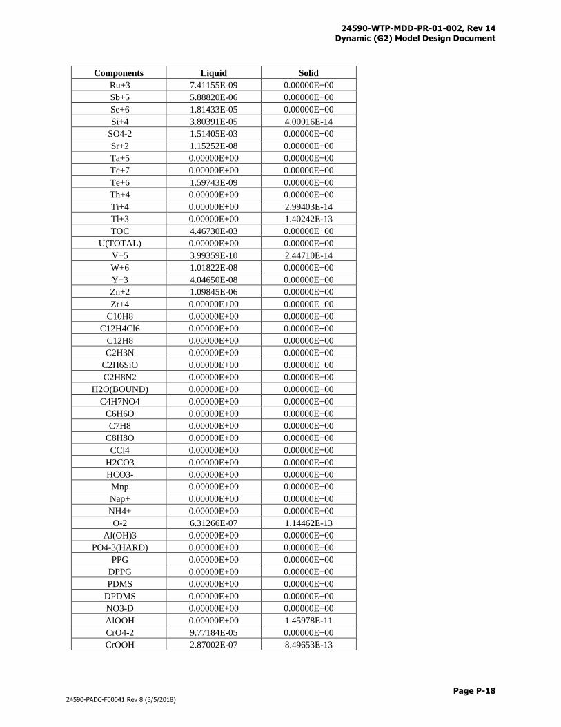
24590-WTP-MDD-PR-01-002, Rev 14 Dynamic (G2) Model Design Document
Page P-18
24590-PADC-F00041 Rev 8 (3/5/2018)
Components Liquid Solid
Ru+3 7.41155E-09 0.00000E+00
Sb+5 5.88820E-06 0.00000E+00
Se+6 1.81433E-05 0.00000E+00
Si+4 3.80391E-05 4.00016E-14
SO4-2 1.51405E-03 0.00000E+00
Sr+2 1.15252E-08 0.00000E+00
Ta+5 0.00000E+00 0.00000E+00
Tc+7 0.00000E+00 0.00000E+00
Te+6 1.59743E-09 0.00000E+00
Th+4 0.00000E+00 0.00000E+00
Ti+4 0.00000E+00 2.99403E-14
Tl+3 0.00000E+00 1.40242E-13
TOC 4.46730E-03 0.00000E+00
U(TOTAL) 0.00000E+00 0.00000E+00
V+5 3.99359E-10 2.44710E-14
W+6 1.01822E-08 0.00000E+00
Y+3 4.04650E-08 0.00000E+00
Zn+2 1.09845E-06 0.00000E+00
Zr+4 0.00000E+00 0.00000E+00
C10H8 0.00000E+00 0.00000E+00
C12H4Cl6 0.00000E+00 0.00000E+00
C12H8 0.00000E+00 0.00000E+00
C2H3N 0.00000E+00 0.00000E+00
C2H6SiO 0.00000E+00 0.00000E+00
C2H8N2 0.00000E+00 0.00000E+00
H2O(BOUND) 0.00000E+00 0.00000E+00
C4H7NO4 0.00000E+00 0.00000E+00
C6H6O 0.00000E+00 0.00000E+00
C7H8 0.00000E+00 0.00000E+00
C8H8O 0.00000E+00 0.00000E+00
CCl4 0.00000E+00 0.00000E+00
H2CO3 0.00000E+00 0.00000E+00
HCO3- 0.00000E+00 0.00000E+00
Mnp 0.00000E+00 0.00000E+00
Nap+ 0.00000E+00 0.00000E+00
NH4+ 0.00000E+00 0.00000E+00
O-2 6.31266E-07 1.14462E-13
Al(OH)3 0.00000E+00 0.00000E+00
PO4-3(HARD) 0.00000E+00 0.00000E+00
PPG 0.00000E+00 0.00000E+00
DPPG 0.00000E+00 0.00000E+00
PDMS 0.00000E+00 0.00000E+00
DPDMS 0.00000E+00 0.00000E+00
NO3-D 0.00000E+00 0.00000E+00
AlOOH 0.00000E+00 1.45978E-11
CrO4-2 9.77184E-05 0.00000E+00
CrOOH 2.87002E-07 8.49653E-13
24590-WTP-MDD-PR-01-002, Rev 14 Dynamic (G2) Model Design Document
Page P-19
24590-PADC-F00041 Rev 8 (3/5/2018)
The size of commissioning hot feed is constrained by: a) hot feed compositions itself; b) commissioning
schedule; and c) melter production rate. The actual commissioning hot feed batch size will be determined
through a trial-and-error approach, for example, prepare a hot feed batch large enough to support
commissioning test to the end, cumulate the hot feed volume during hot commissioning, make batch size
adjustment based on the cumulated hot feed volume from the trial run.
Fate of Naphthalene
Naphthalene is injected to the melters during spike tests. It is an organic compound with the formula
C10H8. Naphthalene is the simplest polycyclic aromatic hydrocarbon, and is a white crystalline solid with
a characteristic odor that is detectable at concentrations as low as 0.08 ppm by mass. Naphthalene has a
density of 1.14 g/cm3, a melting point of 80.26°C and a boiling point of 218°C. Because of its lower
melting and boiling points, much of it will evaporate/sublime and boil away at the cold cap in the melter
without being burned. Consequently, some will pass though the offgas system untreated.
Naphthalene in the LOP/LVP offgas streams shall appear in the gas phase, but in G2 its existence is
tracked in the liquid phase as the G2 liquid/solid component list already tracks C10H8. Naphthalene will
be added to the gas component list in future G2 version releases.
Melter reaction:
C10H8 (l,s) + 12O2 (g) → 10CO2 (g) + 4H2O (g) (Conversion = 7.4%, DF comes from BARD Table 3.2-
2)
Naphthalene Decontamination factors for the rest of the offgas treatment system come from Table C-5 of
document 24590-WTP-RPT-PE-11-010, WTP Feed and Organic Generation Rates and Decontamination
Factors for 2011-2012 Emission Report.
SBS split:
Per 24590-WTP-MCR-PENG-17-0015, 33% of the C10H8 entering the SBS will be captured.
Thermal catalytic oxidizer reaction:
C10H8 (l,s) + 12O2 (g) → 10CO2 (g) + 4H2O (g) (Conversion = 95%)
EMF evaporator split (derivation is discussed in Attachment A1 of 24590-WTP-MCR-PENG-17-0015):
y = 0.011675x-1.002317
where:
y = efficiency factor, or fraction retained (unitless)
x = evaporator overheads to bottoms ratio (unitless)
This correlation is based on:
Henry’s LAW constant 𝑘𝐻0 = 2.1 mol/l·atm at 298 ºK
Evaporator pressure P = 0.078 atm
Evaporator temperature T = 323 °K
Evaporator condenser split:
24590-WTP-MDD-PR-01-002, Rev 14 Dynamic (G2) Model Design Document
Page P-20
24590-PADC-F00041 Rev 8 (3/5/2018)
The EMF evaporator condenser split is thought to behave like the SBS, therefore 33% of the C10H8
entering the condenser will be removed and sent to the effluent stream.
LAW Glass Model Changes
Melter feeds with low sodium and/or high halide concentrations may cause viscosity of glasses going out
of validity range. Modify the LAW glass model for mitigation:
50.02 batch
glass
batch
SiO
M
AIF
Then
batch
glassbatch
glass
batch
SiO
batch
glass
batch
ONabatch
ONa MM
A
M
AA
50.022
2
batch
glass
batch
SiO MA 50.02
Other Model Changes
The current G2 logic enforces a “rotational order” on the LFP trains such that the LFP-VSL-00001 and LFP-VSL-
00003 vessels receive alternately. The “rotational order” operation gives a predictable outcome of the next MFPV
that will receive glass formers, therefore allowing the Glass Former Facility to prepare a formula ahead of time.
The “rotational order” logic is modified to a “rotational plus one-train-only” logic to accommodate the different
startup schedules of trains 1 and 2. The “rotational plus one-train-only” logic allows the two trains to operate in
rotational order when both melters are up, and allows one train to run while the other train is idle.
24590-WTP-MDD-PR-01-002, Rev 14 Dynamic (G2) Model Design Document
Page Q-i
24590-PADC-F00041 Rev 8 (3/5/2018)
Appendix Q
G2 Bundle Model Files
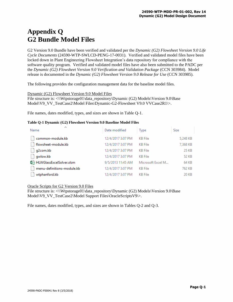
24590-WTP-MDD-PR-01-002, Rev 14 Dynamic (G2) Model Design Document
Page Q-1
24590-PADC-F00041 Rev 8 (3/5/2018)
Appendix Q
G2 Bundle Model Files
G2 Version 9.0 Bundle have been verified and validated per the Dynamic (G2) Flowsheet Version 9.0 Life
Cycle Documents (24590-WTP-SWLCD-PENG-17-0031). Verified and validated model files have been
locked down in Plant Engineering Flowsheet Integration’s data repository for compliance with the
software quality program. Verified and validated model files have also been submitted to the PADC per
the Dynamic (G2) Flowsheet Version 9.0 Verification and Validation Package (CCN 303984). Model
release is documented in the Dynamic (G2) Flowsheet Version 9.0 Release for Use (CCN 303985).
The following provides the configuration management data for the baseline model files.
Dynamic (G2) Flowsheet Version 9.0 Model Files
File structure is: <\\Wtpstorage01\data_repository\Dynamic (G2) Models\Version 9.0\Base
Model\V9_VV_TestCase2\Model Files\Dynamic-G2-Flowsheet V9.0 VVCase2R1\>.
File names, dates modified, types, and sizes are shown in Table Q-1.
Table Q-1 Dynamic (G2) Flowsheet Version 9.0 Baseline Model Files
Oracle Scripts for G2 Version 9.0 Files
File structure is: <\\Wtpstorage01\data_repository\Dynamic (G2) Models\Version 9.0\Base
Model\V9_VV_TestCase2\Model Support Files\OracleScriptsV9\>.
File names, dates modified, types, and sizes are shown in Tables Q-2 and Q-3.

24590-WTP-MDD-PR-01-002, Rev 14 Dynamic (G2) Model Design Document
Page Q-2
24590-PADC-F00041 Rev 8 (3/5/2018)
Table Q-2 Oracle Scripts for G2 Version 9.0 Files (Table Updates)
Table Q-3 Oracle Scripts for G2 Version 9.0 Files (Compilation and Indexing)
Matlab Scripts for G2 Version 9.0 Files
File structure is: <\\Wtpstorage01\data_repository\Dynamic (G2) Models\Version 9.0\Base
Model\V9_VV_TestCase2\Model Support Files\MatlabScriptsV9\>.
File names, dates modified, types, and sizes are shown in Table Q-4.
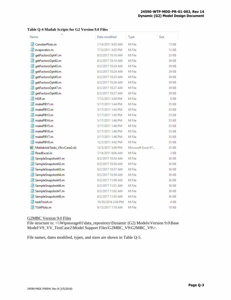
24590-WTP-MDD-PR-01-002, Rev 14 Dynamic (G2) Model Design Document
Page Q-3
24590-PADC-F00041 Rev 8 (3/5/2018)
Table Q-4 Matlab Scripts for G2 Version 9.0 Files
G2MBC Version 9.0 Files
File structure is: <\\Wtpstorage01\data_repository\Dynamic (G2) Models\Version 9.0\Base
Model\V9_VV_TestCase2\Model Support Files\G2MBC_V9\G2MBC_V9\>.
File names, dates modified, types, and sizes are shown in Table Q-5.
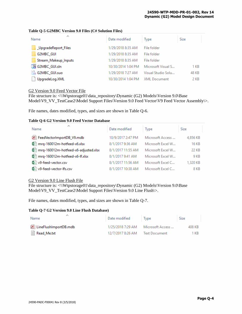
24590-WTP-MDD-PR-01-002, Rev 14 Dynamic (G2) Model Design Document
Page Q-4
24590-PADC-F00041 Rev 8 (3/5/2018)
Table Q-5 G2MBC Version 9.0 Files (C# Solution Files)
G2 Version 9.0 Feed Vector File
File structure is: <\\Wtpstorage01\data_repository\Dynamic (G2) Models\Version 9.0\Base
Model\V9_VV_TestCase2\Model Support Files\Version 9.0 Feed Vector\V9 Feed Vector Assembly\>.
File names, dates modified, types, and sizes are shown in Table Q-6.
Table Q-6 G2 Version 9.0 Feed Vector Database
G2 Version 9.0 Line Flush File
File structure is: <\\Wtpstorage01\data_repository\Dynamic (G2) Models\Version 9.0\Base
Model\V9_VV_TestCase2\Model Support Files\Version 9.0 Line Flush\>.
File names, dates modified, types, and sizes are shown in Table Q-7.
Table Q-7 G2 Version 9.0 Line Flush Database)