Embed Size (px)
Citation preview
Dynamic design optimization of turbine-compressorunit by Ocvirk and Dubois elastohydrodynamic
equations and Craig-Bampton approachDiego Acerbo
HSE at Bonatti S.p.A.Via Nobel, 2 A , 43122 Parma (Italy)
email: [email protected]
Abstract—This paper presents the results obtained analysingthe dynamic behaviour and natural vibration modes of thecomponents of a turbine-compressor unit, connected by toothedcoupling. The study was undertaken with the aim of improvingthe dynamic behaviour of the system, identifying some criticalcharacteristics, mainly linked to problems of misalignment whichlead to elevated vibration levels in some bearings and to therupture of the lubrication film. An accurate 3D parametricvirtual model of the system was used, integrating FEM andMultibody calculation programmes to perform a dynamic anal-ysis of the various components considered as deformable bodies.Information regarding some characteristics significant for thedynamics of the system was obtained in experimental trials,allowing the validation of the numerical models. In particular,the contact of the teeth of the turbine and compressor hubswith the teeth of the coupling bell were simulated, as well asthe hydrodynamic effect of the lubrication in the shaft bearings.The analysis of the results highlighted the need to use modelswith deformable elements, and allowed the determination of thelimiting conditions of misalignment.
Index Terms—3D Flexible modeling, Computational dynamicanalysis, misalignmen, bearings, lubrication film.
I. INTRODUCTION
Management of a modern petrochemical plant, where thesound functioning of the machines installed guarantees thereliability and continuity of production, must include contin-uous monitoring by means of dedicated systems. Checkingfor vibration is essential in verifying the correct functioningof mechanical systems and will evidence possible anomaliesat their incipient stage [1], [2], [3], [4], [5], [6], [7]. Thepresent study examines a steam turbine driving a centrifugecompressor installed in an ethylene refrigeration cycle, partof the thermal cracking unit at the Enichem plant at Priolo(Sicily). Lately, different tools and methodologies have beenemployed to study this typology of machinery [8], [9]. Amultibody model, composed of flexible parts and developedwith the ADAMS programme, was used to simulate thedynamic behaviour of the two rotors, turbine and compressor,linked by a toothed coupling. The model, validated by com-parison with experimental data obtained using the monitoringsystem, was found to be particularly useful in the analysis ofbreakdowns, allowing the simulation of misalignment due to
Copyright © 2017 held by the authors.
jibbing of the coupling. The modeling methodology followedit is similar to that described by Cali et al. [10], [11].
The simplified Reynolds equations proposed by Ocvirk andDubois [12] for short bearings were used to simulate thehydrodynamic reaction of the bearing on the pivot.
II. TURBO-COMPRESSOR UNIT
The P2005A turbo-compressor in the ethylene productionplant of Enichem Priolo is used to compress the mixture ofhydrocarbon gases emitted at the head of the quench column.The machine, constructed by Nuovo Pignone, consists of threemain parts: the steam driven turbine, the centrifuge compressorwhich compresses the gas, and the toothed coupling whichtransmits the torque from the turbine to the compressor. Theaxial turbine, delivers a maximum power of 20835 kW at 4190rpm. The shaft rests on two radial hydrodynamic bearings ofthe Michell type (tilting pad bearings) and a hydrodynamicaxial thrust bearing of the Kingsbury type. The steam andlubrication oil seals are secured by a series of rings cuton the rotor and mounted on the stator with a labyrinthsystem. The six-stages centrifuge compressor of horizontalopen case type, with three intake flanges and one deliveryflange positioned in the lower half-casing, again rests ontwo segmented hydrodynamic bearings and a Kingsbury-typethrust bearing (Tab. I).
The Maag toothed coupling, Zud8 type, in AISI 8740steel, is 976.3 mm in length with a maximum diameter of383 mm. The two bells, internally toothed, rest on the hubsand are connected together by a sleeve collar; two metal O-rings, pressure mounted in circumference slots cut into the
26
teeth of the bell, allow the bell-cylinder system an axial slipof 6 mm. The hubs, toothed externally with 88 teeth, arekeyed on the turbine and compressor shafts; two keys andtwo threaded locking rings prevent, respectively, tangentialand axial movement. The smaller longitudinal dimensionsof the hub teeth compared to those of the bells, combinedwith radial and tangential gap, allow the shafts to becomemisaligned. A gas balancing system, which uses a disk keyedto the shaft, makes it possible to limit the axial thrust andthe vibrations. To prevent excessive vibrations from damagingthe seals, during operation a control system verifies thatradial movement at the bearings never exceeds the allowedtollerances (0.24 ÷ 0.28mm for the compressor bearings and0.3 ÷ 0.358mm for the turbine bearings).
III. NUMERICAL MODEL
The numerical model was developed using: the ADAMscalculation programme to construct the multibody model ofthe turbo-compressor; and the MSC/NASTRAN calculationprogramme which, through modal analysis of the components,was used to generate transfer files simulating the flexiblebehaviour of the parts in the multibody code [13], [14]. Theapproach followed in order to consider the bodies flexiblewas the modal approach developed by Craig and Bampton[15], which allows the number of generalised coordinates tobe reduced to a minimum and offers greater freedom in thedefinition of the constraint conditions at the boundary points.
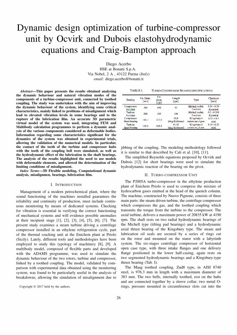
The transfer file contains the stiffness and damping matricesof dimensions (6Nx6N), where N is the number of points usedin modelling the flexible parts; five for the turbine, two forthe coupling and twelve for the compressor. A characteristicaspect of this modelling is the use of kinetic reference systems,KRF (Kinematic Reference Frame), integral with each rigidpart making up the discretized flexible body. In this approach,each substructure of the FEM is represented by a superelementcharacterised by the above stiffness and damping matrices[16].The movements of each substructure are calculated locallywith respect to the corresponding KRF; the overall elasticdeformation of the flexible body is obtained from the set ofsingle movements of the rigid parts into which it is discretized.The definition of the matrix of concentrated mass is obtainedthrough the localisation of a centre of mass for each part,with the inertial properties referring to it. The mass of eachpart is independent of the rest of the system, so that the extra-diagonal terms are eliminated from the mass matrix. On thebasis of the blueprints supplied by MAAG and using digitalphotogrammetry acquisition as described in [17], [18], CAD3D geometries were developed for the following parts: thecompressor shaft; the turbine shaft; the six rotors; the thrustequaliser; the Kingsbury rings of the thrust bearings; all theparts of the diffusors of the keyed stages in the rotor; thethreaded locking rings which axially constrain the rotors anddiffusors; the hubs of the toothed coupling keyed to the statorand the locking rings which constrain them axially (Fig. 1).
The construction of the finite element model required asimplification of these geometries, eliminating some features
Fig. 1. 3D parametric model (top); flexible multibody elements (top).
irrelevant to the dynamic behaviour. The number of hexahedralelements and nodes are reported in Table II.
IV. HYDRODYNAMIC BEARINGS
Particular attention was paid to the modelling of the hy-drodynamic bearings, on which the dynamic stability of thesystem depends.
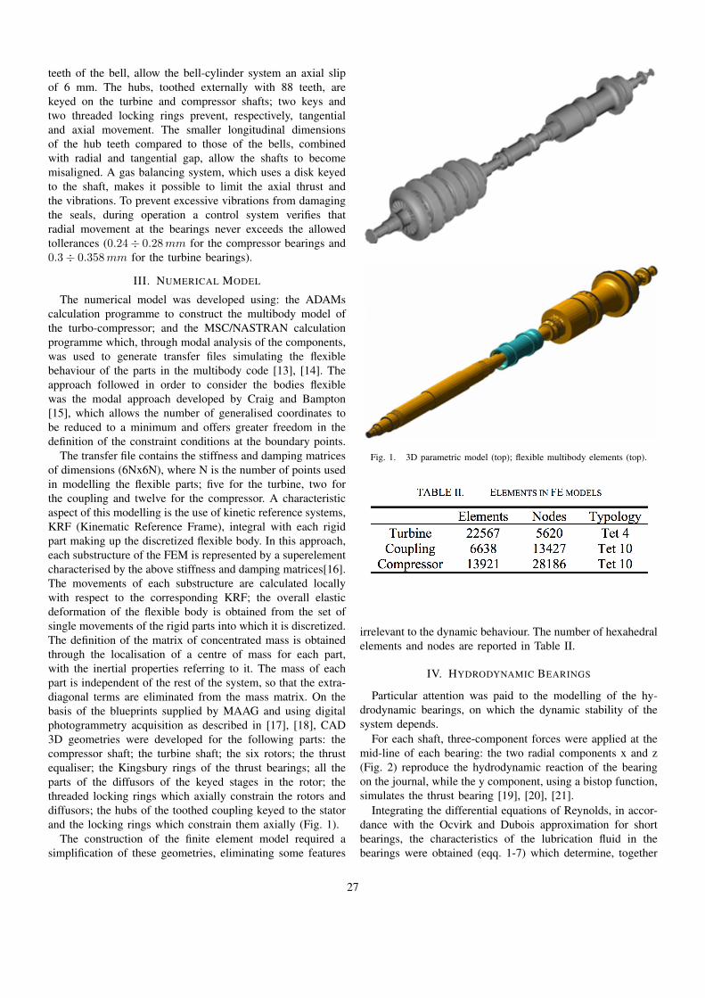
For each shaft, three-component forces were applied at themid-line of each bearing: the two radial components x and z(Fig. 2) reproduce the hydrodynamic reaction of the bearingon the journal, while the y component, using a bistop function,simulates the thrust bearing [19], [20], [21].
Integrating the differential equations of Reynolds, in accor-dance with the Ocvirk and Dubois approximation for shortbearings, the characteristics of the lubrication fluid in thebearings were obtained (eqq. 1-7) which determine, together
27
Fig. 2. Transversal cross-section of the bearing.
with the static component of the load, the elastohydrodynamicreaction of the bearing on the pivot (eq. 8).
kXY =η0 ωb rb b
3 ε0c3
[sin2Φ0
(1 − ε20)2+
+3π ε0 cosΦ0 sinΦ0
4(1 − ε20)52
+2(1 + ε20) cos2Φ0
(1 − ε20)3
] (1)
kXZ =η0 ωb rb b
3
c3
[π(1 + 2ε20) sin2Φ0
4(1 − ε20)52
+
+ε0 (1 + 3ε20) cosΦ0 sinΦ0
(1 − ε20)3+
π cos2Φ0
4(1 − ε20)32
] (2)
kY Z =η0 ωb rb b
3
c3
[− π sin2Φ0
4(1 − ε20)32
+
+ε0 (1 + 3ε20) cosΦ0 sinΦ0
(1 − ε20)3− π (1 + 2ε20) cos2Φ0
4(1 − ε20)52
] (3)
kZZ =η0 ωb rb b
3 ε0c3
[2(1 + ε20)sin2Φ0
(1 − ε20)3+
−3π ε0 cosΦ0 sinΦ0
4(1 − ε20)52
+cos2Φ0
(1 − ε20)2
] (4)
rXX =η0 rb, b
3
c3
[π sin2Φ0
2(1 − ε20)32
+
+4 ε0 cosΦ0 sinΦ0
(1 − ε20)2+π (1 + 2ε20) cos2Φ0
(1 − ε20)52
] (5)
Fig. 3. Bearing site of loading.
rXZ = rZX =η0 rb b
3 ε0c3
[− 4 sin2Φ0
(1 − ε20)2+
+3π ε0 cosΦ0 sinΦ0
2(1 − ε20)52
− cos2Φ0
2(1 − ε20)2
] (6)
rZZ =η0 rb b
3
c3
[π (1 + 2ε20) sin2Φ0
2(1 − ε20)52
+
−4 ε0 cosΦ0 sinΦ0
(1 − ε20)2+
π 2Φ0
2(1 − ε20)32
] (7)
[FX(t)FX(t)
]=
[FX(X0, Z0, 0, 0)
0
]+
−[kXX kXZ
kZX kZZ
] [(X −X0)(Z − Z0)
]−[rXX rXZ
rZX rZZ
] [X
Z)
] (8)
The static components of the load, determined at eachequilibrium configuration (X0, Y0), on varying the velocity,are shown in Fig. 3, while the static reactions of the bearingsare reported in Tab. III.
V. CONTACT BETWEEN THE TEETH
Three-component vector forces were used to model theforces exchanged between the teeth of the hubs and those ofthe bells. Using IMPACT and BISTOP functions, these vectorforces limit the axial, radial and tangential movements of thehubs inside the bells.
The axial movement of the sleeve collar-bells system(±3mm) is limited by the z components of the forces ofcontact between the teeth simulating the behaviour of the two
28
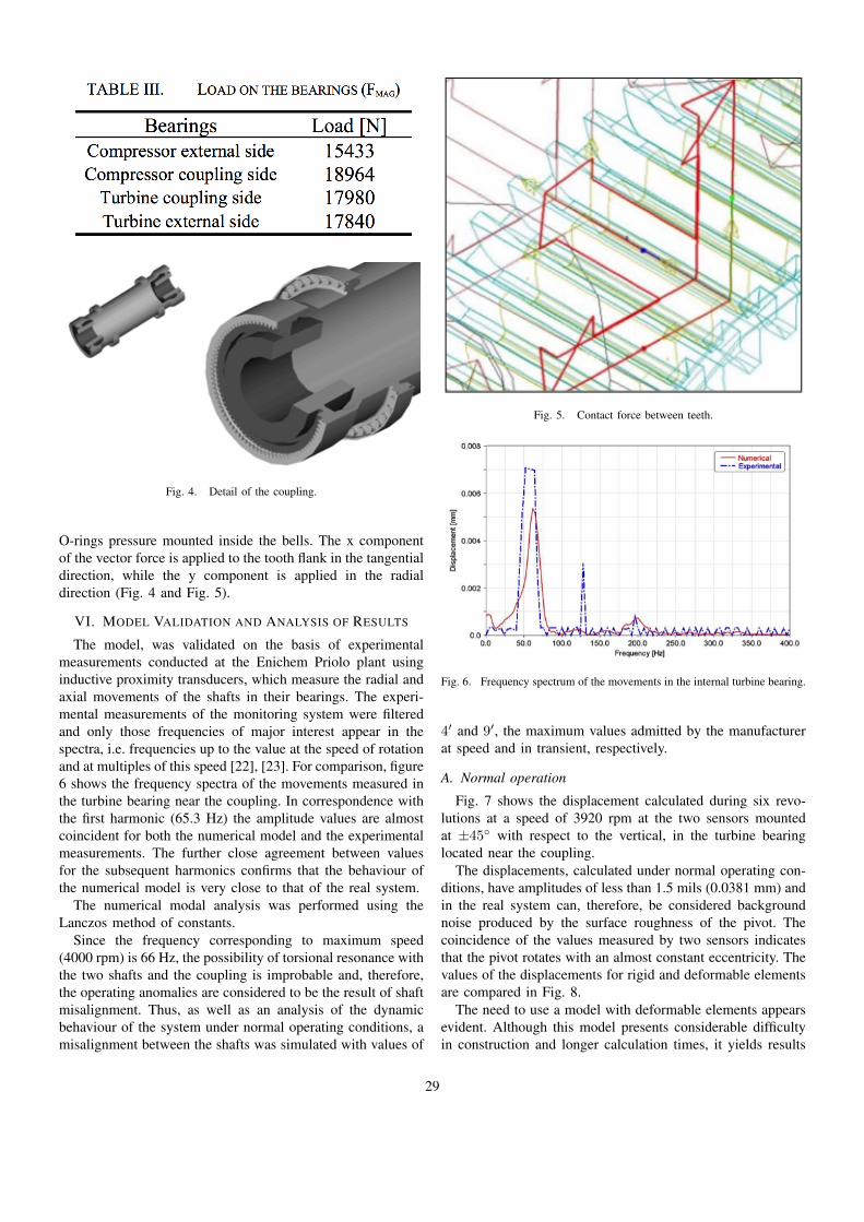
Fig. 4. Detail of the coupling.
O-rings pressure mounted inside the bells. The x componentof the vector force is applied to the tooth flank in the tangentialdirection, while the y component is applied in the radialdirection (Fig. 4 and Fig. 5).
VI. MODEL VALIDATION AND ANALYSIS OF RESULTS
The model, was validated on the basis of experimentalmeasurements conducted at the Enichem Priolo plant usinginductive proximity transducers, which measure the radial andaxial movements of the shafts in their bearings. The experi-mental measurements of the monitoring system were filteredand only those frequencies of major interest appear in thespectra, i.e. frequencies up to the value at the speed of rotationand at multiples of this speed [22], [23]. For comparison, figure6 shows the frequency spectra of the movements measured inthe turbine bearing near the coupling. In correspondence withthe first harmonic (65.3 Hz) the amplitude values are almostcoincident for both the numerical model and the experimentalmeasurements. The further close agreement between valuesfor the subsequent harmonics confirms that the behaviour ofthe numerical model is very close to that of the real system.
The numerical modal analysis was performed using theLanczos method of constants.
Since the frequency corresponding to maximum speed(4000 rpm) is 66 Hz, the possibility of torsional resonance withthe two shafts and the coupling is improbable and, therefore,the operating anomalies are considered to be the result of shaftmisalignment. Thus, as well as an analysis of the dynamicbehaviour of the system under normal operating conditions, amisalignment between the shafts was simulated with values of
Fig. 5. Contact force between teeth.
Fig. 6. Frequency spectrum of the movements in the internal turbine bearing.
4′ and 9′, the maximum values admitted by the manufacturerat speed and in transient, respectively.
A. Normal operation
Fig. 7 shows the displacement calculated during six revo-lutions at a speed of 3920 rpm at the two sensors mountedat ±45◦ with respect to the vertical, in the turbine bearinglocated near the coupling.
The displacements, calculated under normal operating con-ditions, have amplitudes of less than 1.5 mils (0.0381 mm) andin the real system can, therefore, be considered backgroundnoise produced by the surface roughness of the pivot. Thecoincidence of the values measured by two sensors indicatesthat the pivot rotates with an almost constant eccentricity. Thevalues of the displacements for rigid and deformable elementsare compared in Fig. 8.
The need to use a model with deformable elements appearsevident. Although this model presents considerable difficultyin construction and longer calculation times, it yields results
29
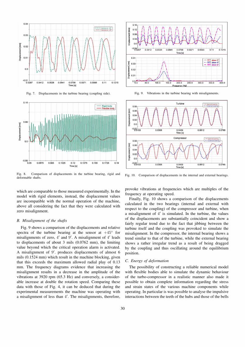
Fig. 7. Displacements in the turbine bearing (coupling side).
Fig. 8. Comparison of displacements in the turbine bearing, rigid anddeformable shafts.
which are comparable to those measured experimentally. In themodel with rigid elements, instead, the displacement valuesare incompatible with the normal operation of the machine,above all considering the fact that they were calculated withzero misalignment.
B. Misalignment of the shafts
Fig. 9 shows a comparison of the displacements and relativespectra of the turbine bearing at the sensor at +45◦ formisalignments of zero, 4′ and 9′. A misalignment of 4′ leadsto displacements of about 3 mils (0.0762 mm), the limitingvalue beyond which the critical operation alarm is activated.A misalignment of 9′. produces displacements of almost 6mils (0.1524 mm) which result in the machine blocking, giventhat this exceeds the maximum allowed radial play of 0.13mm. The frequency diagrams evidence that increasing themisalignment results in a decrease in the amplitude of thevibrations at 3920 rpm (65.3 Hz) and conversely, a consider-able increase at double the rotation speed. Comparing thesedata with those of Fig. 4, it can be deduced that during theexperimental measurements the machine was operating witha misalignment of less than 4′. The misalignments, therefore,
Fig. 9. Vibrations in the turbine bearing with misalignments.
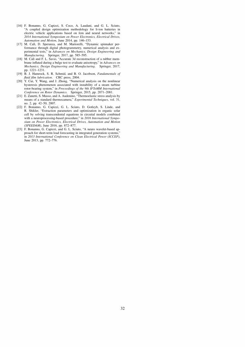
Fig. 10. Comparison of displacements in the internal and external bearings.
provoke vibrations at frequencies which are multiples of thefrequency at operating speed.
Finally, Fig. 10 shows a comparison of the displacementscalculated in the two bearings (internal and external withrespect to the coupling) of the compressor and turbine, whena misalignment of 4′ is simulated. In the turbine, the valuesof the displacements are substantially coincident and show afairly regular trend due to the fact that jibbing between theturbine itself and the coupling was provoked to simulate themisalignment. In the compressor, the internal bearing shows atrend similar to that of the turbine, while the external bearingshows a rather irregular trend as a result of being draggedby the coupling and thus oscillating around the equilibriumposition.
C. Energy of deformation
The possibility of constructing a reliable numerical modelwith flexible bodies able to simulate the dynamic behaviourof the turbo-compressor in a realistic manner also made itpossible to obtain complete information regarding the stressand strain states of the various machine components whileoperating. In particular is was possible to analyse the impulsiveinteractions between the teeth of the hubs and those of the bells
30
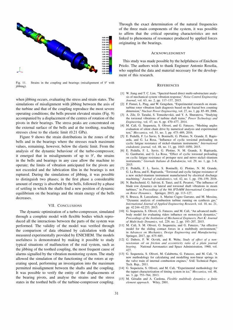
Fig. 11. Strains in the coupling and bearings (misalignment of 9′ withjibbing).
when jibbing occurs, evaluating the stress and strain states. Thesimulations of misalignment with jibbing between the axis ofthe turbine and that of the coupling reproduce the most severeoperating conditions; the bells present elevated strains (Fig. 9)accompanied by a displacement of the centres of rotation of thepivots in their bearings. The stress peaks are concentrated onthe external surface of the bells and at the toothing, reachingstresses close to the elastic limit (0.21 GPa).
Figure 9 shows the strain distributions in the zones of thebells and in the bearings where the stresses reach maximumvalues, remaining, however, below the elastic limit. From theanalysis of the dynamic behaviour of the turbo-compressor,it emerged that in misalignments of up to 9′, the strainsin the bells and bearings in any case allow the machine tooperate; the limits of vibration anticipated for the pivots arenot exceeded and the lubrication film in the bearings is notruptured. During the simulations of jibbing, it was possibleto distinguish two phases; in the first phase a considerableamount of energy is absorbed by the bells, followed by a phaseof settling in which the shafts find a new position of dynamicequilibrium on the bearings and the strain energy of the bellsdecreases.
VII. CONCLUSIONS
The dynamic optimization of a turbo-compressor, simulatedthrough a complete model with flexible bodies which repro-duced all the interactions between the parts of the system wasperformed. The validity of the model was verified throughthe comparison of data obtained by calculation with thatmeasured experimentally provided by ENICHEM. The modelsusefulness is demonstrated by making it possible to studytypical situations of malfunction of the real system, such asthe jibbing of the toothed coupling, the most frequent cause ofalarms signalled by the vibration monitoring system. The studyallowed the simulation of the functioning of the rotors at op-erating speed, performing an investigation into the maximumpermitted misalignment between the shafts and the coupling.It was possible to verify the entity of the displacements ofthe bearing pivots, and analyse the strains and the stressstates in the toothed bells of the turbine-compressor coupling.
Through the exact determination of the natural frequenciesof the three main components of the system, it was possibleto affirm that the critical operating characteristics are notlinked to phenomena of resonance produced by applied forcesoriginating in the bearings.
ACKNOWLEDGMENT
This study was made possible by the helpfulness of EnichemPriolo. The authors wish to thank Engineer Antonio Rosolia,who supplied the data and material necessary for the develop-ment of this research.
REFERENCES
[1] W. Jiang and T. C. Lim, “Spectral-based direct multi-substructure analy-sis of mechanical system vibration response,” Noise Control EngineeringJournal, vol. 63, no. 2, pp. 117–137, 2015.
[2] F. Fumei, L. Ping, and W. Gengshen, “Experimental research on steam-turbine rotor vibration fault diagnosis based on the fractal box countingdimension,” Nuclear Power Engineering, vol. 27, no. 1, pp. 85–89, 2006.
[3] A. Zile, D. Taradai, S. Tomashevskii, and Y. A. Shuranova, “Studyingthe torsional vibrations of turbine shaft trains,” Power Technology andEngineering, vol. 47, no. 6, pp. 470–477, 2014.
[4] M. Calı, G. Sequenzia, S. Oliveri, and G. Fatuzzo, “Meshing anglesevaluation of silent chain drive by numerical analysis and experimentaltest,” Meccanica, vol. 51, no. 3, pp. 475–489, 2016.
[5] E. Pedulla, F. Lo Savio, S. Boninelli, G. Plotino, N. Grande, E. Rapis-arda, and G. La Rosa, “Influence of cyclic torsional preloading oncyclic fatigue resistance of nickel–titanium instruments,” Internationalendodontic journal, vol. 48, no. 11, pp. 1043–1050, 2015.
[6] E. Pedulla, F. L. Savio, G. Plotino, N. M. Grande, S. Rapisarda,G. Gambarini, and G. La Rosa, “Effect of cyclic torsional preloadingon cyclic fatigue resistance of protaper next and mtwo nickel–titaniuminstruments,” Giornale Italiano di Endodonzia, vol. 29, no. 1, pp. 3–8,2015.
[7] E. Pedulla, F. L. Savio, S. Boninelli, G. Plotino, N. M. Grande,G. La Rosa, and E. Rapisarda, “Torsional and cyclic fatigue resistance ofa new nickel-titanium instrument manufactured by electrical dischargemachining,” Journal of endodontics, vol. 42, no. 1, pp. 156–159, 2016.
[8] N. Bachschmid, G. Salvini, E. Tanzi, and E. Pesatori, “The influence ofblade row dynamics on lateral and torsional shaft vibrations in steamturbines,” in Proceedings of the 9th IFToMM International Conferenceon Rotor Dynamics. Springer, 2015, pp. 113–127.
[9] S. Brusca, R. Lanzafame, A. Marino Cugno Garrano, and M. Messina,“Dynamic analysis of combustion turbine running on synthesis gas,”International Journal of Applied Engineering Research, vol. 10, no. 21,pp. 42 244–42 253, 2015.
[10] G. Sequenzia, S. Oliveri, G. Fatuzzo, and M. Calı, “An advanced multi-body model for evaluating riders influence on motorcycle dynamics,”Proceedings of the Institution of Mechanical Engineers, Part K: Journalof Multi-body Dynamics, vol. 229, no. 2, pp. 193–207, 2015.
[11] M. Calı, S. M. Oliveri, G. Sequenzia, and G. Fatuzzo, “An effectivemodel for the sliding contact forces in a multibody environment,”in Advances on Mechanics, Design Engineering and Manufacturing.Springer, 2017, pp. 675–685.
[12] G. Dubois, F. W. Ocvirk, and R. Wehe, Study of effect of a non-newtonian oil on friction and eccentricity ratio of a plain journalbearing. National Aeronautics and Space Administration, 1960, vol.427.
[13] G. Sequenzia, S. Oliveri, M. Calabretta, G. Fatuzzo, and M. Cali, “Anew methodology for calculating and modelling non-linear springs inthe valve train of internal combustion engines,” SAE Technical Paper,Tech. Rep., 2011.
[14] G. Sequenzia, S. Oliveri, and M. Calı, “Experimental methodology forthe tappet characterization of timing system in ice,” Meccanica, vol. 48,no. 3, pp. 753–764, 2013.
[15] M. Geradin and A. Cardona, Flexible multibody dynamics: a finiteelement approach. Wiley, 2001.
31
[16] F. Bonanno, G. Capizzi, S. Coco, A. Laudani, and G. L. Sciuto,“A coupled design optimization methodology for li-ion batteries inelectric vehicle applications based on fem and neural networks,” in2014 International Symposium on Power Electronics, Electrical Drives,Automation and Motion, June 2014, pp. 146–153.
[17] M. Calı, D. Speranza, and M. Martorelli, “Dynamic spinnaker per-formance through digital photogrammetry, numerical analysis and ex-perimental tests,” in Advances on Mechanics, Design Engineering andManufacturing. Springer, 2017, pp. 585–595.
[18] M. Calı and F. L. Savio, “Accurate 3d reconstruction of a rubber mem-brane inflated during a bulge test to evaluate anisotropy,” in Advances onMechanics, Design Engineering and Manufacturing. Springer, 2017,pp. 1221–1231.
[19] B. J. Hamrock, S. R. Schmid, and B. O. Jacobson, Fundamentals offluid film lubrication. CRC press, 2004.
[20] Y. Cui, Y. Wang, and J. Zhong, “Numerical analysis on the nonlinearhysteresis phenomenon associated with instability of a steam turbinerotor-bearing system,” in Proceedings of the 9th IFToMM InternationalConference on Rotor Dynamics. Springer, 2015, pp. 2071–2081.
[21] E. Zanetti, S. Musso, and A. Audenino, “Thermoelastic stress analysis bymeans of a standard thermocamera,” Experimental Techniques, vol. 31,no. 2, pp. 42–50, 2007.
[22] F. Bonanno, G. Capizzi, G. L. Sciuto, D. Gotleyb, S. Linde, andR. Shikler, “Extraction parameters and optimization in organic solarcell by solving transcendental equations in circuital models combinedwith a neuroprocessing-based procedure,” in 2016 International Sympo-sium on Power Electronics, Electrical Drives, Automation and Motion(SPEEDAM), June 2016, pp. 872–877.
[23] F. Bonanno, G. Capizzi, and G. L. Sciuto, “A neuro wavelet-based ap-proach for short-term load forecasting in integrated generation systems,”in 2013 International Conference on Clean Electrical Power (ICCEP),June 2013, pp. 772–776.
32