Embed Size (px)
Citation preview
TECHNICS liJ
JBR
Dynamic Compaction of ■ Metal and Ceramic Powders
National Materials Advisory Board
Commission on Engineering and Technological Systems
National Research Council ~
NATIONAL RESEARCH COUNCIL COMMISSION ON ENGINEERING AND TECHNICAL SYSTEMS
NATIONAL MATERIALS ADVISORY BOARD
The purpose of the National Materials Advisory Board is the advancement of materials science and engineering in the national interest.
CHAIRMAN PAST CHAIRMAN
Dr. Donald J. McPherson Vice President and Director of Technology (Retired) Kaiser Aluminum & Chemical Corporation 300 Lakeside Drive Oakland, CA 94643
Mr. William D. Manly Senior Vice President Cabot Corporation 125 High Street Boston, MA 02110
Members
Dr. Arden L. Bement, Jr. Vice President, Technology Resources Science and Technical Department TRW, Inc. 23555 Euclid Ave. Cleveland, OH 44117
Dr. William J.Burlant Director, Lexington Laboratory The Kendall Co. Lexington, MA 02173
Dr. James C. Burrows Vice President Charles River Associates 200 Clarendon Street John Hancock Tower, 43rd Floor Boston, MA 02116
Dr. Raymond F. Decker Vice President, Research Michigan Technological University Houghton, MI 49931
Mr. Edward J. Dulis President Crucible Research Center Colt Industries P.O. Box 88 Pittsburgh, PA 15230
Dr. Brian R. T. Frost Division Director, Materials Science Argonne National Laboratory 9700 South Cass Avenue Argonne, IL 60439
Dr. Serge Gratch Director of Chemistry Science Lab Engineering & Research Staff Ford Motor Co, P,0, Box 2053 Dearborn, MI 48121
Dr. Nick Holonyak, Jr. Professor Electronic Engineering University of lUinois-Urbana Dept. of Electrical Engineering Urbana.IL 61801
Dr. Paul J. Jorgenson Stanford Research Institute 333 Ravenswood Avenue Menlo Park, CA 94025
Dr. Alan Lawley Professor Metallurgical Engineering Drexel University Department of Materials Engineering Philadelphia, PA 19104
Dr. Raymond F. Mikesell W. E. Miner Professor of Economics University of Oregon Department of Economics Eugene, OR 97403
Dr. David L. Morrison President IIT Research Institute 10 West 35th Street Chicago, IL 60616
Dr. David Okrent Professor of Engineering & Applied Science University of California, Los Angeles 5532 Boelter Hill Los Angeles, CA 90024
Dr, R. Byron Pipes Director, Center for
Composite Materials Department of Mechanical &
Aerospace Engineering University of Delaware Newark, DE 19711
Professor James R. Rice Gordon McKay Professor of
Engineering Sciences and Geophysics Division of Applied Sciences Harvard University Peirce Hall Cambridge, MA 02138
Dr. Brian M. Rushton Vice President, Research & Development Air Products & Chemicals, Inc. P,0. Box 538 AlIentown.PA 18105
Dr. WiUiamP. Slichter Executive Director, Research Materials Science and Engineering Division Bell Laboratories 600 Mountain Avenue Murray Hill, NJ 07974
Dr, William A. Vogely Professor and Head Department of Mineral Economics Pennsylvania State University University Park, PA 16802
Dr, Robert P. Wei Department of Mechanical Engineering
and Mechanics Lehigh University Bethlehem, PA 18015
Dr. Albert R.C. Westwood Director, Martin Marietta Labs Martin Marietta Corporation 1450 South Rolling Road Baltimore, MD 21227
NMAB STAFF
K.M. Zwilsky, Executive Director
1/83
UNCLASSIFIED SECURITY CLASSIFICATION OF THIS PAGE (Whmn Dmm Bntmndi
REPORT DOCUMENTATION PAGE READ INSTRUCTIONS BEFORE COMPLETING FORM
I. REPORT NUMBER
NiyiAB-394
2. COVT ACCESSION NO. 1. RECIPIENT'S CATALOG NUMBER
«. TITLE (and Subtltlm)
Dynamic Cortpaction of Metal and Ceramic Powders
5. TYPE OF REPORT A PERIOD COVERED
Final Report
6. PERFORMING ORG. REPORT NUMBER NMAB-394
a. CONTRACT OR GRANT NUMBER<'«)
MDA-903-82-C-0434
7. AUTHORf«J
Coitmittee on Dynamic Conpaction of Metal and Ceramic Powders
9. PERFORMING ORGANIZATION NAME AND ADDRESS
National Materials Advisory Board National Research Coioncil 2101 Constitution Avenue, N.W., Wash. D.C. 20418
10. PROGRAM ELEMENT. PROJECT, TASK AREA A WORK UNIT NUMBERS
Final Report
II. CONTROLLING OFFICE NAME AND ADDRESS 12. REPORT DATE
March 1983 13. NUMBER OF PAGES
103 14. MONITORING AGENCY NAME ft ADDRESSC// dllUnnl from ControlUna Olllea)
Department of Defense/National Aeronautics and Space Administration
Washington, D.C. 20301
15. SECURITY CLASS, (ol thim rmport)
Unclassified
15a. DECLASSIFI CATION/DOWNGRADING SCHEDULE
16. DISTRIBUTION STATEMENT (ol thit Rmport)
improved for Public Release; Distribution Unlimited.
17. DISTRIBUTION STATEMENT (ot thm mbalrael tiltrmd In Block 30, II dlllorent from Report)
18. SUPPLEMENTARY NOTES
19. KEY WORDS (Contlttuo on rcraraa tido J/naca««ary and Identity by block number)
Dynamic Corpaction Metal and Ceramic Powders Recrystallization and Grain Growth Characterization
Coirputer Coding Applications Shock Wave Phenomena
20. ABSTRACT (Conllrtue an rererme mida H nmceeemy and Identity by black mmtber)
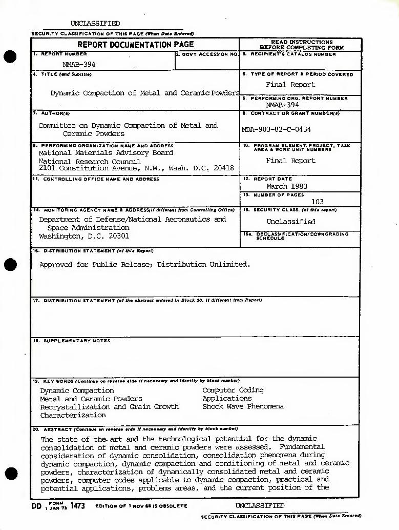
The state of the- art and the technological potential for the dynamic consolidation of metal and ceramic pDwiers were assessed. Fundamental consideration of dynamic consolidation, consolidation phenomena during dynamic ccnpaction, dynamic compaction and conditioning of metal and ceramic powders, characterization of dynamically consolidated metal and ceramic powders, corputer codes applicable to dynamic compaction, practical and potential applications, problems areas, and the current position of the
DD tJA-HT) 1473 COrTlON OF I MOV «S IS OBSOLETE UNCLASSIFIED
SECURITY CLASSIFICATION OF THIS PAGE fWhao Oa(a Entered)
UNCLASSIFIED SECURITY CLASSIFICATION OF THIS PAGEfW>>an Dmtm MnttMl)
United States in dynamic ccnpaction were examined. Based on its conclusions, the conmittee reconmended that a systeitiatic study of the dynamic conpaction process should be conducted; existing techniques should be inproved and new ones developed for monitoring of dynamic events as close to the microscale as possible for tertperatures, shock velocities, pressures and particle motion; data from systematic experiments should be utilized to form data information for modeling codes; coordination among those investigating dynamic corrpaction should be maintained; a sufficiently funded, sustained, coordinated, and concentrated research and developnent effort should be initiated to strengthen the United States position in the dynamic corrpaction field.
UNCLASSIFIED
tCCUNITY CLASSIFICATION OF THIS PAGEf»7i«n Dmim Enffd)
DYNAMIC COMPACTION OF METAL AND CERAMIC POWDERS
Report of the
Committee on Dynamic Compaction of Metal and Ceramic Powders
National Materials Advisory Board Commission on Engineering and Technical Systems
National Research Council
NMAB-394 National Academy Press
Washington, D.C. 198 3
NOTICE: The project that is the subject of this report was approved by the Governing Board of the National Research Council, whose members are drawn from the Councils of the National Academy of Sciences, the National Academy of Engineering, and the Institute of Medicine. The members of the committee responsible for the report were chosen for their special competences and with regard for appropriate balance.
The report has been reviewed by a group other than the authors according to procedures approved by a Report Review Committee consisting of members of the National Academy of Sciences, the National Academy of Engineering, and the Institute of Medicine.
The National Research Council was established by the National Academy of Sciences in 1916 to associate the broad community of science and technology with the Academy's purposes of furthering knowledge and of advising the federal government. The Council operates in accordance with general policies determined by the Academy under the authority of its congressional charter of 1863, which established the Academy as a private, nonprofit, self-governing membership corporation. The Council has become the principal operating agency of both the National Academy of Sciences and the National Academy of Engineering in the conduct of their services to the government, the public, and the scientific and engineering communities. It is administered jointly by both Academies and the Institute of Medicine. The National Academy of Engineering and the Institute of Medicine were established in 1964 and 1970, respectively, under the charter of the National Academy of Sciences.
This study by the National Materials Advisory Board was conducted under Contract No. MDA-903-82-C-0434 with the DOD/NASA.
This report is for sale by the Defense Technical Information Center, Cameron Station, Virginia 22314.
Printed in the United States of America.
il
ABSTRACT
The Committee on Dynamic Compaction of Metal and Ceramic Powders has assessed the state of the art and the technological potential for the dynamic consolidation of metal and ceramic powders. It examined the fundamental consideration of dynamic consolidation, consolidation phenomena during dynamic compaction, dynamic compaction and conditioning of metal and ceramic powders, characterization of dynamically consolidated metal and ceramic powders, computer codes applicable to dynamic compaction, practical and potential applications, problem areas, and the current position of the United States in dynamic compaction.
Based on its conclusions, the committee recomended that a systematic study of the dynamic compaction process should be conducted; existing techniques should be improved and new ones developed to permit the monitoring of the dynamic events as close to the microscale as possible for temperatures, shock velocities, pressures, and particle motion; data and information from the systematic experiments recommended above should be utilized to form data information for the modeling codes; coordination among those investigating dynamic compaction should be maintained; a sufficiently funded, sustained, coordinated, and concentrated research and development effort should be initiated to strengthen the United States position in the dynamic compaction field.
ill
PREFACE
At the request of the Department of Defense, the National Materials Advisory Board of the National Research Council established the Committee on Dynamic Compaction of Metal and Ceramic Powders to critically assess the state of the art and the technological potential for the dynamic consolidation of metal and ceramic powders. Dynamic compaction techniques offer the potential for enhancing self sintering or for greatly reducing densification temperatures of metal and ceramic powders with finer particles, more uniform particle size distributions, and highly metastable microstructures (particularly rapidly solidified materials).
Valuable presentations of data and opinions were made and other assistance was offered by several individuals during the study. The committee therefore wishes to thank the following persons: Roy W. Rice, U.S. Naval Research Laboratory; Charles S. Yust, Oak Ridge National Laboratory; Dennis E. Grady, Sandia Laboratories; James R. Asay, Sandia Laboratories; Marc A. Meyers, New Mexico Institute of Technology; Bernard H. Kear, United Technologies Corporation; Howard H. Lieberman, General Electric Company; Derek Raybould, Institute Cerac, Ecublens, Switzerland; Robert A. Graham, Sandia Laboratories; Gordon A. Bruggeman, U.S. Army Materials and Mechanics Research Center; R. Bruce MacDonald, U.S. Office of Naval Research; Lt. Col. Loren Jacobson, Defense Advanced Research Projects Agency; Col. Joseph D. Morgan, U.S. Air Force Systems Command; Yuki Horie, U.S. Army Research Office; and Richard M. Spriggs, National Materials Advisory Board.
Vonne D. Linse Chairman
COMMITTEE ON
DYNAMIC COMPACTION OF METAL AND CERAMIC POWDERS
Chairman
VONNE D. LINSE, Fabrication and Quality Assurance Section, Battelle Laboratories, Columbus, Ohio
Members
OSWALD R. BERGMANN, Diamond and DETACLAD Explosive Products Division, E.I. duPont de Nemours Company, Coatesville, Pennsylvania
CARL F. CLINE, Materials Science Division, Lawrence Livermore National Laboratories, Livermore, California
JIM D. MOTE, Metallurgy and Materials Science Division, Denver Research Institute, University of Denver, Colorado
HAYNE PALMOUR III, Department of Materials Engineering, North Carolina State University, Raleigh
THOMAS VASILOS, High Temperature Materials Processing, AVCO Croporation, Wilmington, Massachusetts.
MAN F. YAN, Bell Laboratories, Inc., Murray Hill, New Jersey
LIAISON REPRESENTATIVES
j GORDON BRUGGEMAN, Metals Research Division, U.S. Army Materials and t Mechanics Research Center, Watertown, Massachusetts
STEVE H. CARPENTER, Materials Science Division, U.S. Army Research Office, Research Triangle Park, North Carolina
THOMAS K. GLASGOW, Lewis Research Center, NASA, Cleveland, Ohio
JOHN D. MCKINLEY, Center for Materials Sciences, National Bureau of Standards, Washington, D.C.
GERALD L. MOSS, Solid Mechanics Branch, U.S. Army Ballistic Research Laboratory, Aberdeen Proving Ground, Maryland
JEROME PERSH, Office of the Deputy Under Secretary of Defense for Research and Engineering, Washington, D.C.
ROBERT POHANKA, Office of Naval Research, Arlington, Virginia
ROBERT RUH, AFWAL-MLLM, Wright-Patterson Air Force Base, Ohio
EDWARD E. VAN REUTH, Materials Science Division, Defense Advanced Research Projects Agency, Arlington, Virginia
NMAB Staff
RICHARD M. SPRIGGS, Staff Scientist
Vll
CONTENTS
Page
Chapter 1 Summary, Conclusions and Recommendations 1
Summary 1 Conclusions 2 Recommendations 3
Chapter 2 The Point of Departure: A Brief Summary of Traditional Metal and Ceramic Process Methods 5
Chapter 3 Fundamental Considerations 9
Shock Wave Pnenomena 9 Generating Shock Waves in Materials 17 Instrumenting and Monitoring Highly Dynamic Events 22
Chapter 4 Consolidation and Related Phenomena During Dynamic Compaction 29
Materials Responses 29 Describing Elementary Processes in Dynamic
Compaction of Powders 30 Recrystallization and Grain Growth Phenomena
During Dynamic Compaction 34
Chapter 5 Dynamic Compaction and Conditioning of Metal and Ceramic Powders 41
Historical Background 41 Complexity-Specialization 41 Reviews of the State-of-the-Art 41 Characterization of Shock-Induced Changes
in Particulate Materials 42 Dynamic Compaction Routes 42 Modeling of Densification of Shock Conditioned
(or Otherwise Activated) Powders 61 Preconditioning of Powders by Shock Waves 63
IX
Chapter 6 Characterization of Dynamically Consolidated Metal
and Ceramic Powders 71
Chapter 7 Dynamic Compaction Modeling and Computer Codes 77
Chapter 8 Practical and Potential Applications 79
Synthesis and Transformation of Materials 79 Powder Conditioning 79 Powder Forming 79 Rapidly Solidified Materials 81
Chapter 9 Problem Areas 83
Safety 83 Environmental Concerns 84 Economic Considerations 84 Geometries, Shapes, Sizes and Scaling, etc. 84 Cracking 87 Energy Source Consistency , 90
X
FIGURES AND TABLES
Page
Figures
1 Shock wave in a solid body 10
2 Rankine-Hugoniot curve 12
3 Equation of state and shock structures in elastic-plastic solid 14
4 Hugoniot for a powder material 15
5 Comparison of the waste energies in solid vs. porous materials 16
6 Shock waves induced in various materials by normally incident plane detonation waves 18
7 Assembly for explosive compaction of powder 19
8 Arrangement for powder compaction using explosively driven flyer plate 20
9 Flash X-ray photograph of collapsing cylinder during explosive powder compaction 24
10 Statistical distributions in particle coordination 31
11 Computer-derived cross-sections of initial and densified packings of uniform spheres 32
12 Schematic time-temperature-transformation diagram for re crystallization and precipitation processes 37
13 Flash X-ray radiographs showing mechanism of explosive shock treatment of powders 43
14 Dynamic differential calorimetry of explosively shocked Linde A alumina powder 44
15 Line broadening 3 as a function of amount of explosive 45
16 Line breadth B of the (113) X-ray diffractometer peak of AI2O3 before and after explosive shock treatment 46
17 Explosively shocked Linde A powder, TEM X60,000 47
XI
Page
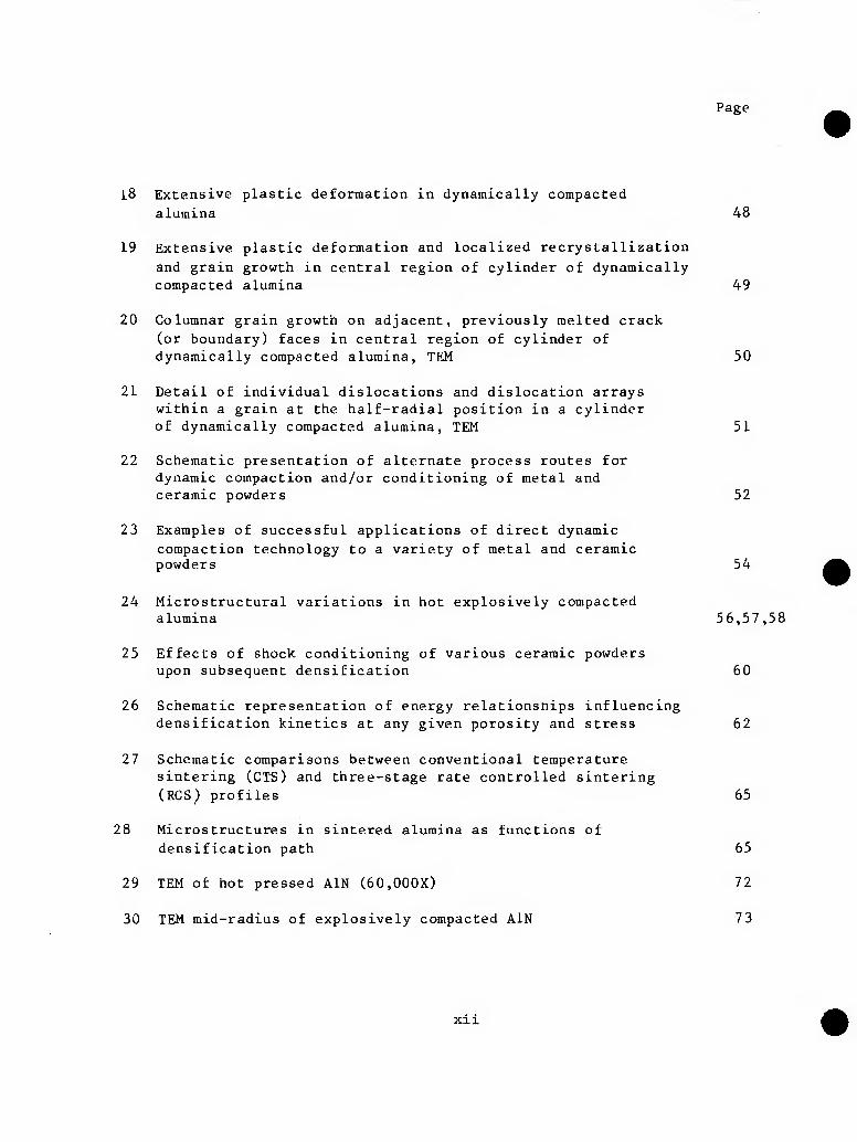
i8 Extensive plastic deformation in dynamically compacted
alumina 48
19 Extensive plastic deformation and localized recrystallization
and grain growth in central region of cylinder of dynamically compacted alumina 49
20 Columnar grain growth on adjacent, previously melted crack (or boundary) faces in central region of cylinder of dynamically compacted alumina, TEM 50
21 Detail of individual dislocations and dislocation arrays within a grain at the half-radial position in a cylinder of dynamically compacted alumina, TEM 51
22 Schematic presentation of alternate process routes for dynamic compaction and/or conditioning of metal and ceramic powders 52
23 Examples of successful applications of direct dynamic compaction technology to a variety of metal and ceramic powders 54
24 Microstructural variations in hot explosively compacted alumina 56,57,58
25 Effects of shock conditioning of various ceramic powders upon subsequent densification 60
26 Schematic representation of energy relationsnips influencing densification kinetics at any given porosity and stress 62
27 Schematic comparisons between conventional temperature sintering (CTS) and three-stage rate controlled sintering (RCS) profiles 65
28 Microstructures in sintered alumina as functions of densification path 65
29 TEM of hot pressed AIN (60,000X) 72
30 TEM mid-radius of explosively compacted AIN 73
xil
Page
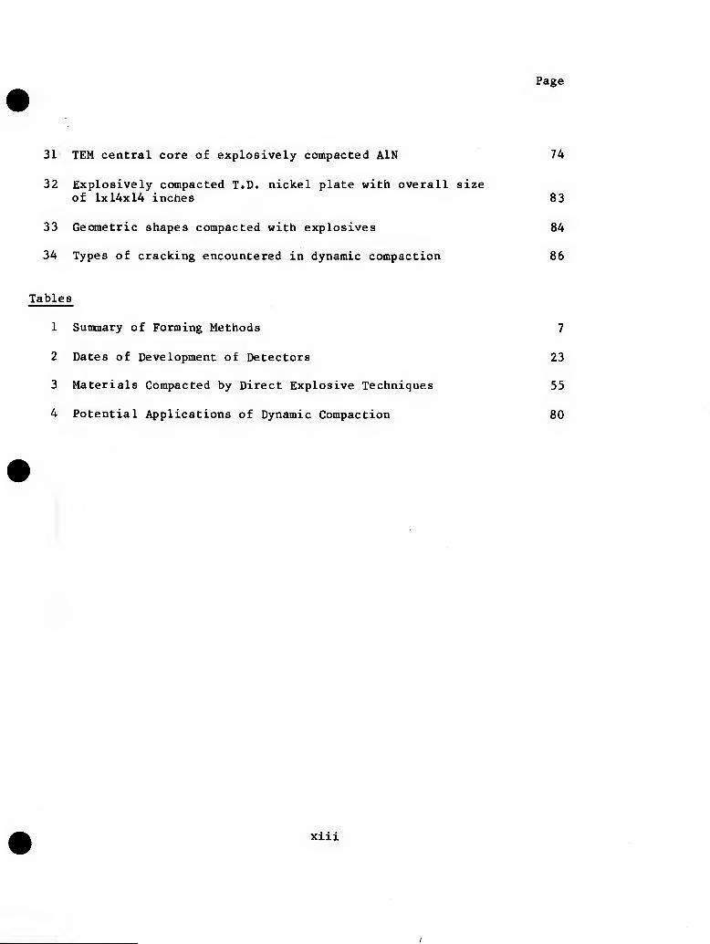
31 TEM central core of explosively compacted AIN 74
32 Explosively compacted T.D. nickel plate with overall size of 1x14x14 inches 83
33 Geometric shapes compacted with explosives 84
34 Types of cracking encountered in dynamic compaction 86
Tables
1 Summary of Forming Methods 7
2 Dates of Development of Detectors 23
3 Materials Compacted by Direct Explosive Techniques 55
4 Potential Applications of Dynamic Compaction 80
xiii
Chapter 1
SUMMARY, CONCLUSIONS, AND RECOMMENDATIONS
SUMMARY
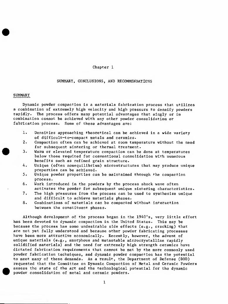
Dynamic powder compaction is a materials fabrication process that utilizes a combination of extremely high velocity and high pressure to densify powders rapidly. The process offers many potential advantages that singly or in combination cannot be achieved with any other powder consolidation or fabrication process. Some of these advantages are:
1. Densities approaching theoretical can be achieved in a wide variety of difficult-to-compact metals and ceramics.
2. Compaction often can be achieved at room temperature without the need for subsequent sintering or thermal treatment.
3. Warm or elevated temperature compaction can be done at temperatures below those required for conventional consolidation with numerous benefits such as refined grain structure.
4. Unique (often nonequillbrium) microstructures that may produce unique properties can be achieved.
5. Unique powder properties can be maintained through the compaction process.
6. Work introduced in the powders by the process shock wave often activates the powder for subsequent unique sintering characteristics.
7. The high pressures from the process can be used to synthesize unique and difficult to achieve materials phases.
8. Combinations of materials can be compacted without interaction between the constituent phases.
Although development of the process began in the 1940's, very little effort has been devoted to dynamic compaction in the United States. This may be because the process has some undesirable side effects (e.g., cracking) that are not yet fully understood and because other powder fabricating processes have been more attractive economically. Recently, however, the advent of unique materials (e.g., amorphous and metastable microcrystalline rapidly solidified materials) and the need for extremely high strength ceramics have dictated fabrication requirements that cannot be met by the more commonly used powder fabrication techniques, and dynamic powder compaction has the potential to meet many of these demands. As a result, the Department of Defense (DOD) requested that the Committee on Dynamic Compaction of Metal and Ceramic Powders assess the state of the art and the technological potential for the dynamic powder consolidation of metal and ceramic powders.
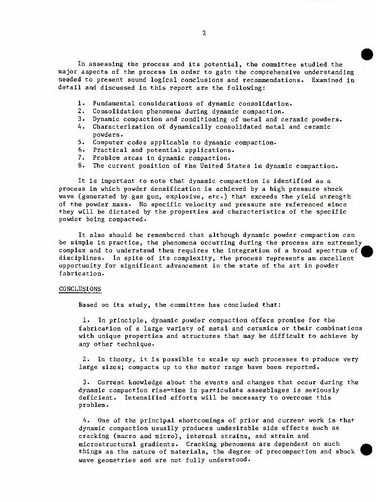
In assessing the process and its potential, the committee studied the major aspects of the process in order to gain the comprehensive understanding needed to present sound logical conclusions and recommendations. Examined in detail and discussed in this report are the following:
1. Fundamental considerations of dynamic consolidation. 2. Consolidation phenomena during dynamic compaction. 3. Dynamic compaction and conditioning of metal and ceramic powders. 4. Characterization of dynamically consolidated metal and ceramic
powders. 5. Computer codes applicable to dynamic compaction. 6. Practical and potential applications. 7. Problem areas in dynamic compaction. 8. The current position of the United States in dynamic compaction.
It is important to note that dynamic compaction is identified as a process in which powder densification is achieved by a high pressure shock wave (generated by gas gun, explosive, etc.) that exceeds the yield strength of the powder mass. No specific velocity and pressure are referenced since they will be dictated by the properties and characteristics of the specific powder being compacted.
It also should be remembered that although dynamic powder compaction can be simple in practice, the phenomena occurring during the process are extremely complex and to understand them requires the integration of a broad spectrum of disciplines. In spite of its complexity, the process represents an excellent opportunity for significant advancement in the state of the art in powder fabrication.
CONCLUSIONS
Based on its study, the committee has concluded that:
1. In principle, dynamic powder compaction offers promise for the fabrication of a large variety of metal and ceramics or their combinations with unique properties and structures that may be difficult to achieve by any other technique.
2. In theory, it is possible to scale up such processes to produce very large sizes; compacts up to the meter range have been reported.
3. Current knowledge about the events and changes that occur during the dynamic compaction rise-time in particulate assemblages is seriously deficient. Intensified efforts will be necessary to overcome this problem.
4. One of the principal shortcomings of prior and current work is that dynamic compaction usually produces undesirable side effects such as cracking (macro and micro), internal strains, and strain and microstructural gradients. Cracking phenomena are dependent on such things as the nature of materials, the degree of precompaction and shock wave geometries and are not fully understood.
5. One of the principal outcomes of dynamic compaction research is likely to be hybrid processing in which the dynamic process is employed to precondition a powder prior to subsequent processing in a more conventional manner.
6. New experimental techniques for instrumenting and monitoring highly dynamic events and the interactions of shock waves with particulate materials are urgently needed. Current methods do not permit the direct observation of dynamic compaction process events in real time and on the microscale level that is desirable.
7. Many of the experiments on dynamically compacted materials have been conducted with little or no attention to the nature and character of the material before, during, or after the process. A significant increase in the level of characterization is vital.
8. The level of effort devoted to dynamic compaction in the United States has been very low and basically uncoordinated. As a result, this country is critically behind others in development of the process.
9. Principal applications of the dynamic process are minimal or lacking.
10. The energy sources used in dynamic compaction in the past have often been unmonitored and inconsistent; therefore, experimental results have been inconsistent and uncorrelatable. This is particularly true with the explosives which have been the major energy source for the process.
RECOMMENDATIONS
Based on its conclusions, the committee recommends that:
1. A systematic study of the dynamic compaction process should be conducted. Model material systems such as rapidly solidified metals, copper, zinc, silicon, aluminum nitride, silicon carbide, magnesium oxide, aluminum oxide, and magnesium aluminate should be used. The original powders should be well characterized with respect to particle size, particle shape, purity, etc., and the goal should be direct dynamic compaction or shock conditioning followed by conventional densification for each system. A systematic correlation should be made between the compaction/shocking conditions and the nature and character of the material after the process in terms of density, microstructure, and system parameters (e.g., shock pressure, attenuation and temperature distributions, as well as shock wave geometry).
2. Existing techniques should be improved and new ones developed to permit the monitoring of the dynamic events as close to the microscale as possible for temperatures, shock velocities, pressures, and particle motion.
3. The data and information from the systematic experiments recommended above should be utilized to form data information for the modeling codes. Due to the complexity of the process, it may be necessary to modify the existing codes or even develop new ones. Codes should be available to handle both the macroscale and microscale aspects of the process, and diagnostic code build-up should be combined with attempts to extrapolate from one material to another.
4. Coordination among those investigating dynamic compaction should be maintained.
5. A sufficiently funded, sustained, coordinated, and concentrated research and development effort should be initiated to strengthen the United States position in the dynamic compaction field.
Chapter 2
THE POINT OF DEPATRURE: A BRIEF SUMMARY OF TRADITIONAL METAL AND CERAMIC PROCESS METHODS
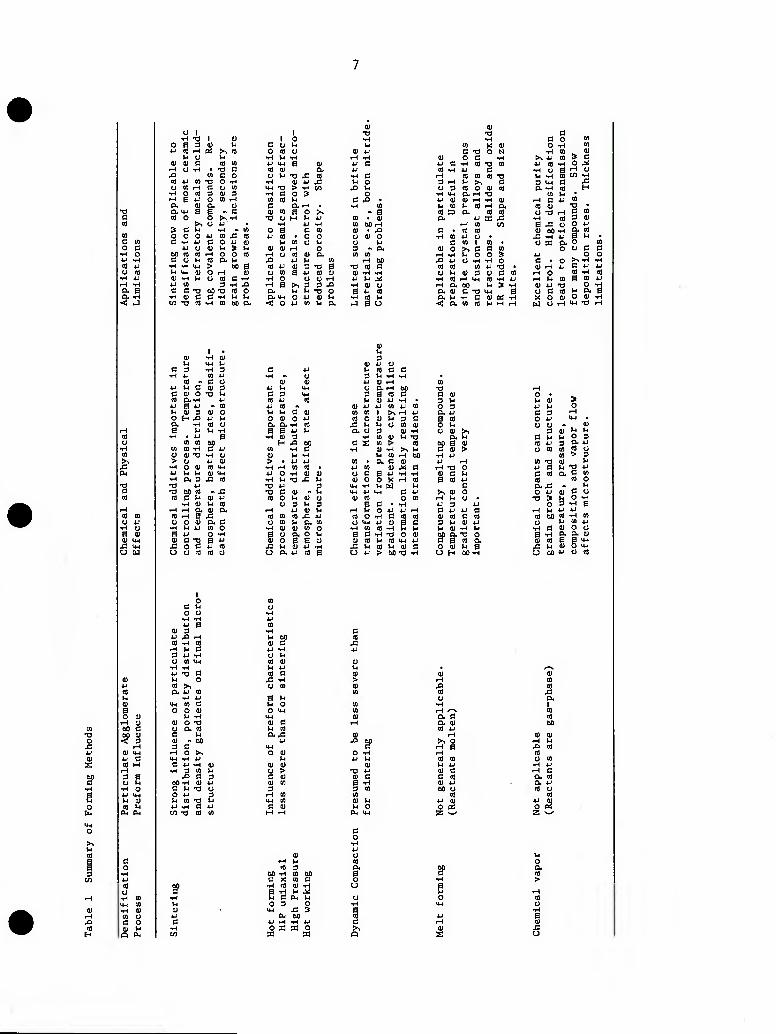
The forming of metals and ceramics traditionally has proceeded by two major process routes: solids or particulate processing, and fluids processing. Fluids processing is characterized by melt forming as well as chemical and physical vapor deposition processing and is not dependent on starting material particle characteristics. Rather, melt and vapor forming temperatures and their control are the dominant parameters. Solids processing, on the other hand, usually is characterized by the consolidation of particulates into preform shape via one of a number of possible intermediate forming methods (e.g., cold pressing, extrusion, slip casting). In general, this is followed by heat treatment at a sufficiently high temperature to cause final densification by the process of sintering. Solids processing is highly dependent on several factors.
1. The nature and characteristics of the powders employed. Particle ■ .] size, shape, surface area, agglomerate structure, impurities, additives,
and their distribution play a major role in affecting cold forming i characteristics, final densification kinetics, and microstructure I development.
2. Forming gradients. These usually are in the form of pressure gradients, occurring during particulate consolidation, that develop
i porosity or density gradients in the cold formed structure. They can result in microstructure discontinuities and shape deformation. An extension of cold forming is the process of hot forming, pressing, or working wherein particulates or particulate preforms are densified under applied pressure at elevated temperatures. Dynamic compaction also may be considered an extension of these basic forming processes and is treated in more detail below.
3. Heat treatment parameters. The variables of time, temperature, and heating rate play a very important role in determining densification kinetics and resulting microstructures. The selection of specific time and temperature criteria often is influenced by original particle and preform characteristics as well as chemical impurity or dopant content.
In effect, the various steps involved in solids processing are virtually dependent on each other in developing final material and process characteristics.
Judicious selection of partlculate characteristics, coupled with suitable processing parameters has led to the development of essentially pore-free, single-phase ceramic compounds with controlled microstructure (e.g., aluminum oxide, magnesium oxide, yttrium oxide, beryllium oxide, barium titanate, lead zirconate titanate, silicon carbide, silicon nitride). For metals, solids processing has been extended to include nickel-cobalt super-base alloys with unique fine-grained microstructures with a high degree of chemical homogeneity.
Table 1 provides a summary of the various applicable forming processes together with dynamic compaction. As a special case of solids processing, dynamic compaction offers the potential for generating fine-grained microstructures at essentially an ultimate level. This coupled with the possiblity of fabricating large forms without the need for large presses and ancillary capital equipment enhances the attraction of explosive compaction in particular.
1 0 (0 o c
■H O
a. a
•H •n 1 (U 0 fi 3 0) l-l JJ « rH « >^ «
U iH (U a C n «
rH 1) •H ■n c .O en C 0 m 4J V) T1 O -H n W3 rH n o in
•H O ffl 3 0) 3 iH H 4-' o tn H a. a) ex u tX «-( Fl B - c n o o >, -rH
3 C ij ^ . m O O O 4J W j: CO C -H 4J C O 4J OJ
4J O d) 1-1 ^ ^
C O Vi to *H -H y-i > *-< Iw (U O TH
dj -H V-i O
a u 00 B
. c w 3 vH .O
c c -o 60 -a n o •H <D C C TH V-I ti en T3 CO -H CO C30 ex
o *-- T3 x: CO 14H ^3 > TH C/l •H C o 3 en CO VJ c ex r-l . (!) CO B o >,
O O CO iH
to 4J O CO
1-1 o -H a ex ex u-i <: o
0) •a
e^ en • o o
en o v^ H o
CO (U (X jj M en 0) 3 -o e a 4-' (u oj
!>^ 3 3 -ea VJ V4 T3 O O 4J (U VJ -H 4J en VJ ex
iH 00 •O CO C
(U -H ^ >J U M •H (1) O a tJ CO T-l CO M •j a U
0) •o c •H fl o CO
w X 0) O •H CO c T) 0 N •H CO Si
(U o C •H >. 4J CO > c 4-i c •H to T3 CO 4-1 CO •H O ^ « •H 4J c •H o 6 iH o TH CO CO CO T3 1-1 •H u CO •rH 3 i-H 1-1 >% C 3 4-( c x: o 3 CO O CU CO cx •H to H
■H U-( P- ^ TJ CO v^ ■U (U OJ rH T-l OJ rH C 4J CO ^ en t-l CO 1-H CL CO OJ T3 • CO ri a (0 to o T3 rH c (0 & 4J ffi ^ 1-1 CO 3 OJ
fH CO en s M o 0 4J C CO CO QJ GO TH a CO
•H CO JJ CJ X •H 4J S 1-1 C CO 1 CO • CJ 31 a o
<U O >^ C c CO 0 u c 1—4 •H u o o 3 4J o ^ 4J CJ •H •H O C ■ o >1 •H
CO CO CO 4J T3 0) f-i 4J c 4J O ^ (U 3 a C CO w O CO •H
•H CO iH U-i CO -H 4J rH h CO a CO M a bO u > TH 0) 4J T3 o a Q) C TJ ■4-1 a O C CO 1-1 & a u •H C 0) ce; ■H X o (U o OJ < a CO (0 t^ M TH M o iH m T3
H (fl c c 3 l-< -H -H
•s
a 0)
o
to - 4-> 1-. 3 c (U o to a -H 4-1 S 4J l-l <U 3 o H ^ a •H n l-l
•H • 4J (0 CO
CO CO •>-( 0) 0) T3
•H O QJ (0 y-i 4J f-j I-i OJ ^
■fl on to * J= CO c u a 4J
•H 01 u CO rH rH ex (U a
CO r-t R j= e> o (U a. c
•H U iJ en o a 4J o TH
OJ C T5 n iJ s: o C 4J to U O CO (0 o
4J CO « V4 M c Oi 0 01 o 4J a O. -H CO a a 4J u
•H o 3 H J2 oo
en •H c eu M •H > JJ *J -rl rH en CO • 4J o ■H 0) 0) •rl VI Tl J= u •o iJ 3 •o C D Vi
CO 0 M OJ o o 3 u 3
r^ 4J 01 iH CO en CO J= 4J o en U & Cfl
•H 0) 01 en o a o ex o u <u o B a ej X h lU 4J •rt o ex tj CO a
o Q,rH ttO T! 3 S CO a C 01 l-l 0) 4J ■H 3 u
01 4-1 4J CO 4J en o 3 CO CO 1 >* rH 4J ex 4J CO o 0) M 3 C S eo
x: u M O CO m 0 U a o 3 OJ •H o 01 >^
*H CO (U u X) a. M 3 X CO > to 00 a 0)
•H 0) •H >. M c 0) > M CO rH 00 ■H u
CD a c 01 U r-i 4J to Q) ^ C rH ■a o o c: a 4J •H ■H 11 c >H QJ o o X iH CO B CO 4J
M-l iH l-l w V4 c U-l 4J ^-^ 3 4J >^ QJ o 0) to O en ,-< U o •
S 3 • •H 4-' 3 u rH t-l o 4J 4J r-4 c 4J 4J C to o -H c to to u CO c CO o l+H 4J cu g c 3 V4 0) 4J
-TH CO CO TH ^ u 01 T4 U B d •H T3 o <u 00 a. -o a 0) CO t-l CO tw 4J 13 a CO (X ^ M CO l-l 01 e: O 0) M B o 4J > bO 13 •H CL) H 00 -H
M 0) 3 4J 1^ o 3 3 rH
0 4J M-l CJ o A <u
3 <u t-l V4
C l-l V-I O 3 CO 4J 3 a 4J o CO CO CO o
CO > 3 to T) OJ l-l 4J e V-I •3 4J c CO a 3 to CB CO o ax: ., u o 4J (U 3 o
t3 0 ^ O
•H •H S
H l-l 4J 4J CO oo CO •H CO o l-l CO 4J
•H 3 (U O O B •H & a OJ 0) CO 0 0 ^
x: VJ a> UH u 0>O 4J O to
01
9> u a
0) B o
00
O c u o o
nH •H 4J a
(U 3 JJ J3 r-i CO -H CO
rH U e3 3 JJ •H u en UH •rl -H JJ T) C3 VJ O CO !>, ex JJ en
■H JJ UH en c O 0 0)
VJ •H 0) o T) o a to c: M 01 . 00 3 0
rH O >-. tJH -rl JJ
e3 JJ •H Oi •H 3 en u
XI c 3 00 -H (U JJ C U T3 O O JJ 3 ;4 CO T3 VH JJ iH t3 JJ e/3 T3 CO en
01 C JJ -H o u CO o; IH JJ CO C3
£ -H
O eo
a 01 01 en
B CO
Xi
o -H 4J l-l
(U Tl 4J
3 •H
CO CO OJ Vi u o
(U <4H
3 o
eu a Q, g)
^§ « a u u 01 a B « 01 u 00 u « tJ 01
f a to 00
0) (U rH IH j:i CO to tl CO
■H JJ rH c ex CO a JJ CO
CO JJ cit n c«( z
J3 to H
00 -rt en 00 a ci X en C o •H to 01 -H u C e3 B- VJ o 0 3 O -H
UH X! 3 a Oj 00 to
JJ M -rl JJ c: O K 33 0 >^
P3 a Q I
Chapter 3
FUNDAMENTAL CONSIDERATIONS
Dynamic compaction is a process in which powder densification is achieved by a high pressure shock wave. In order to understand the phenomena that occur during the process it is first necessary to have a fundamental understanding of the shock wave and its interaction with the material. In the sections that follow, a mathematical description of the shock wave phenomena in condensed materials is developed and related to porous and distended materials similar to powder structures. Also, the methods of generating shock waves in materials along with the current state of the art of instrumentation and monitoring of highly dynamic events is described. It is the intent of this chapter to provide the reader with a summary understanding of these phenomena.
SHOCK WAVE PHENOMENA
The production of shock waves in gases and condensed materials is related to the fact that at high pressures the velocity of sound Increases with increasing pressure. Thus, above some minimum pressure pulse the disturbance steepens until a discontinuity in the state variables is created and a shock wave results.
A mathematical description of the state of the material behind the shock wave, with respect to the state variables ahead of the shock wave, can be obtained by writing the equations for conservation of mass, momentum, and energy, respectively. This yields the well known Rankine-Hugoniot relations (Duvall and Fowles 1963, McQueen et al. 1970, Rice et al. 1958) as outlined below.
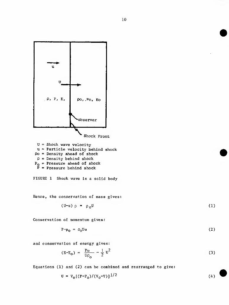
Consider a plane shock front moving through a solid as shown in Figure 1; u equals the particle velocity, p equals the density, T equals the temperature, P equals the pressure, U equals the shock velocity, and E equals the internal energy per unit mass.
The conditions on each side of the shock front are represented in Figure 1, where the subscript o refers to the initial state. If the shock front is moving with a velocity U with respect to laboratory coordinates, the observer sees material entering the shock front with a velocity U and leaving the shock front with a velocity U-u.
10
P, P, E, Po,.Po, Eo
'\ observer
V Shock Front
U = Shock wave velocity u = Particle velocity behind shock
po = Density ahead of shock P = Density behind shock
PQ = Pressure ahead of shock P = Pressure behind shock
FIGURE 1 Shock wave in a solid body
Hence, the conservation of mass gives:
(U-u) p = PQU (1)
Conservation of momentum gives:
P-Po = PoUu (2)
and conservation of energy gives:
Pu (E-EQ) =
Up. 4"^ (3)
Equations (1) and (2) can be combined and rearranged to give;
U = Vo[(P-Po)/(Vo-V)]l/2 (4)
11
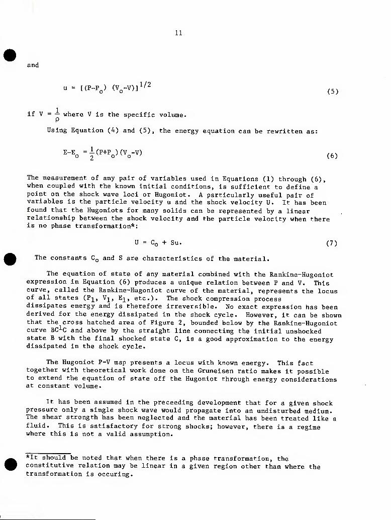
and
u = [(P_p^) (V^-V)]l/2 ^^^
if V = — where V is the specific volume. P
Using Equation (4) and (5), the energy equation can be rewritten as:
E-Eo=|^''''''o)^VV) (6)
The measurement of any pair of variables used in Equations (1) through (6), when coupled with the known initial conditions, is sufficient to define a point on the shock wave loci or Hugoniot. A particularly useful pair of variables is the particle velocity u and the shock velocity U. It has been found that the Hugoniots for many solids can be represented by a linear relationship between the shock velocity and the particle velocity when there is no phase transformation*:
U = Co + Su. (7)
The constants CQ and S are characteristics of the material.
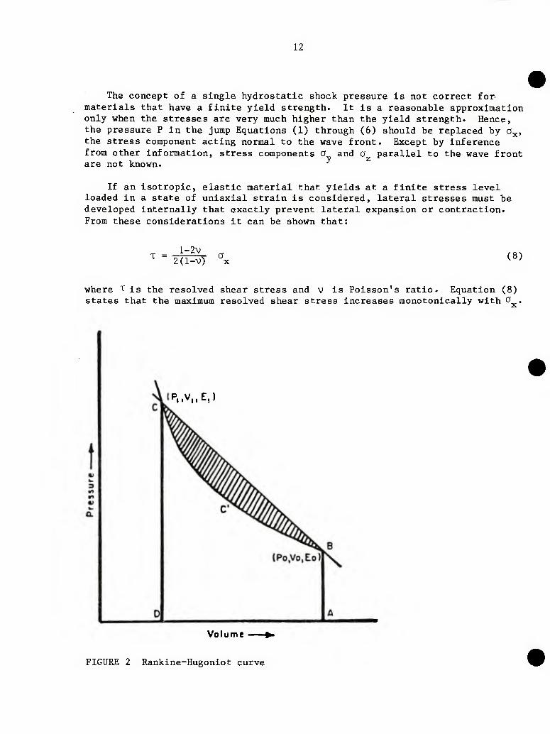
The equation of state of any material combined with the Rankine-Hugoniot expression in Equation (6) produces a unique relation between P and V. This curve, called the Rankine-Hugoniot curve of the material, represents the locus of all states (P]^, Vj^, E^, etc.)* The shock compression process dissipates energy and is therefore irreversible. No exact expression has been derived for the energy dissipated in the shock cycle. However, it can be shown that the cross hatched area of Figure 2, bounded below by the Rankine-Hugoniot curve BC^C and above by the straight line connecting the initial unshocked state B with the final shocked state C, is a good approximation to the energy dissipated in the shock cycle.
The Hugoniot P-V map presents a locus with known energy. This fact together with theoretical work done on the Gruneisen ratio makes it possible to extend the equation of state off the Hugoniot through energy considerations at constant volume.
It has been assumed in the preceeding development that for a given shock pressure only a single shock wave would propagate into an undisturbed medium. The shear strength has been neglected and the material has been treated like a fluid. This is satisfactory for strong shocks; however, there is a regime where this is not a valid assumption.
*It should be noted that when there is a phase transformation, the constitutive relation may be linear in a given region other than where the transformation is occuring.
12
The concept of a single hydrostatic shock pressure is not correct for materials that have a finite yield strength. It is a reasonable approximation only when the stresses are very much higher than the yield strength. Hence, the pressure P in the jump Equations (1) through (6) should be replaced by a the stress component acting normal to the wave front. Except by inference from other information, stress components O and are not known.
x»
O parallel to the wave front
If an isotropic, elastic material that yields at a finite stress level loaded in a state of uniaxial strain is considered, lateral stresses must be developed internally that exactly prevent lateral expansion or contraction. From these considerations it can be shown that:
T = l-2v
2(l-v) X (8)
where T is the resolved shear stress and V is Poisson's ratio. Equation (8) states that the maximum resolved shear stress increases monotonically with o
:P,.V,.E,)
Vo I u m e
FIGURE 2 Rankine-Hugoniot curve
13
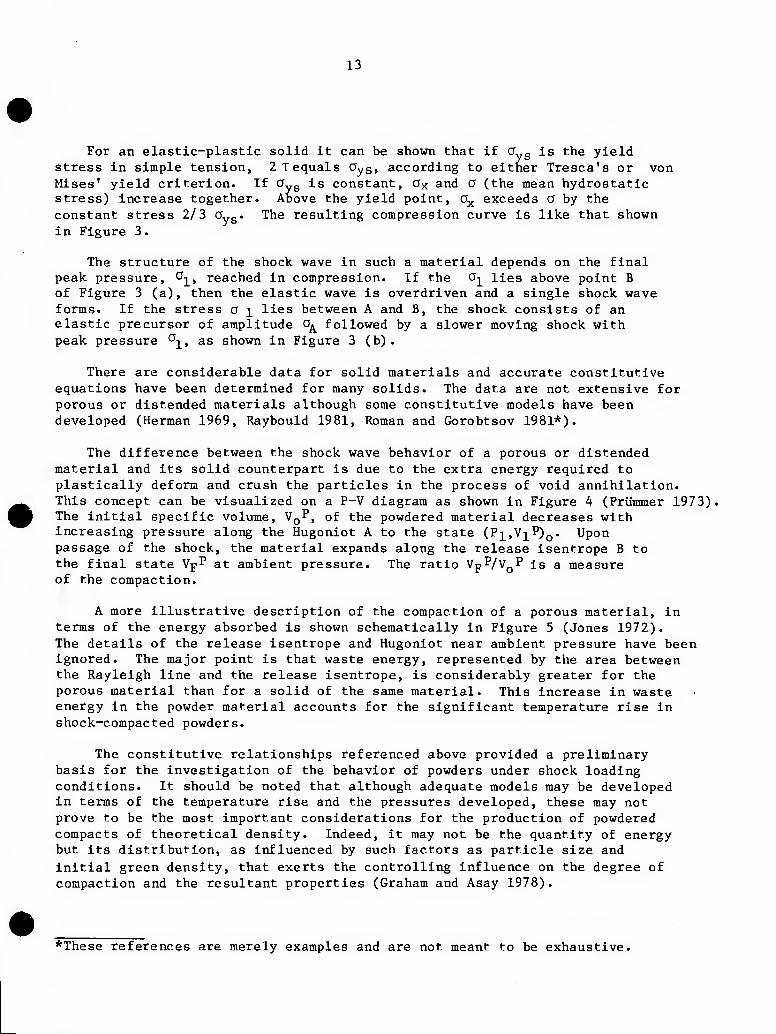
For an elastic-plastic solid it can be shown that if a„g is the yield stress in simple tension, 2Tequals Oys» according to either Tresca's or von Mises' yield criterion. If O g is constant, Ox and O (the mean hydrostatic stress) increase together. Above the yield point, o^ exceeds a by the constant stress 2/3 Oyg. The resulting compression curve is like that shown in Figure 3.
The structure of the shock wave in such a material depends on the final peak pressure, ^■^, reached in compression. If the O-^ lies above point B of Figure 3 (a), then the elastic wave is overdriven and a single shock wave forms. If the stress a \ lies between A and B, the shock consists of an elastic precursor of amplitude 0^ followed by a slower moving shock with peak pressure ^^.f ^^ shown in Figure 3 (b) .
There are considerable data for solid materials and accurate constitutive equations have been determined for many solids. The data are not extensive for porous or distended materials although some constitutive models have been developed (Herman 1969, Raybould 1981, Roman and Gorobtsov 1981*).
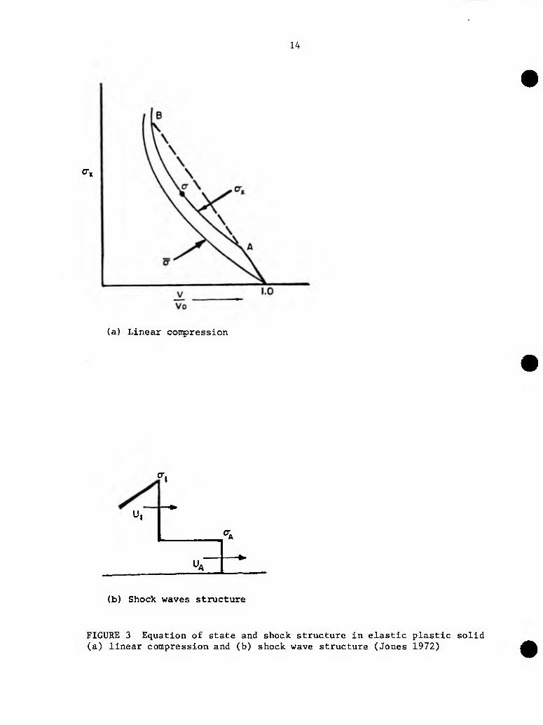
The difference between the shock wave behavior of a porous or distended material and its solid counterpart is due to the extra energy required to plastically deform and crush the particles in the process of void annihilation. This concept can be visualized on a P-V diagram as shown in Figure 4 (Prilmmer 1973). The initial specific volume, VQP, of the powdered material decreases with increasing pressure along the Hugoniot A to the state (PI>VJ^P)Q. Upon passage of the shock, the material expands along the release isentrope B to the final state VpP at ambient pressure. The ratio VJ-P/VQP is a measure of the compaction.
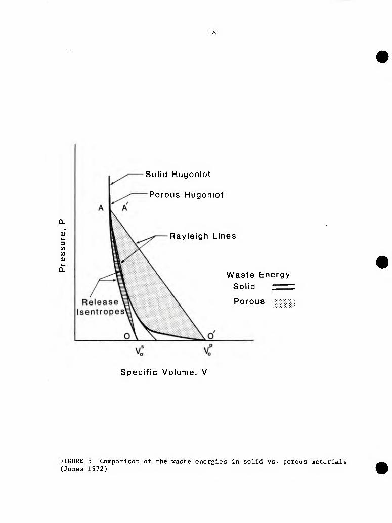
i A more illustrative description of the compaction of a porous material, in terms of the energy absorbed is shown schematically in Figure 5 (Jones 1972). The details of the release isentrope and Hugoniot near ambient pressure have been ignored. The major point is that waste energy, represented by the area between the Rayleigh line and the release isentrope, is considerably greater for the porous material than for a solid of the same material. This increase in waste energy in the powder material accounts for the significant temperature rise in shock-compacted powders.
The constitutive relationships referenced above provided a preliminary basis for the investigation of the behavior of powders under shock loading conditions. It should be noted that although adequate models may be developed in terms of the temperature rise and the pressures developed, these may not prove to be the most important considerations for the production of powdered compacts of theoretical density. Indeed, it may not be the quantity of energy but its distribution, as influenced by such factors as particle size and initial green density, that exerts the controlling influence on the degree of compaction and the resultant properties (Graham and Asay 1978).
*These references are merely examples and are not meant to be exhaustive.
14
(a) Linear compression
U.
U*
OA
(b) Shock waves structure
FIGURE 3 Equation of state and shock structure in elastic plastic solid (a) linear compression and (b) shock wave structure (Jones 1972)
15
OS
a
1 F o
SPECIFIC VOLUME, V
FIGURE 4 Hugoniot for a powder material (Priimmer 1973)
16
CD
w 0
Solid Hugoniot
Porous Hugoniot
Rayleigh Lines
Waste Energy
Solid ^^
Porous
Specific Volume, V
FIGURE 5 Comparison of the waste energies in solid vs. porous materials (Jones 1972)
17
GENERATING SHOCK WAVES IN MATERIALS
Shock waves can be created in materials by the detonation of an explosive in contact with the material or by the impact of a projectile on the material. Some of the various methods of accomplishing this are discussed below.
Direct Contact Explosive
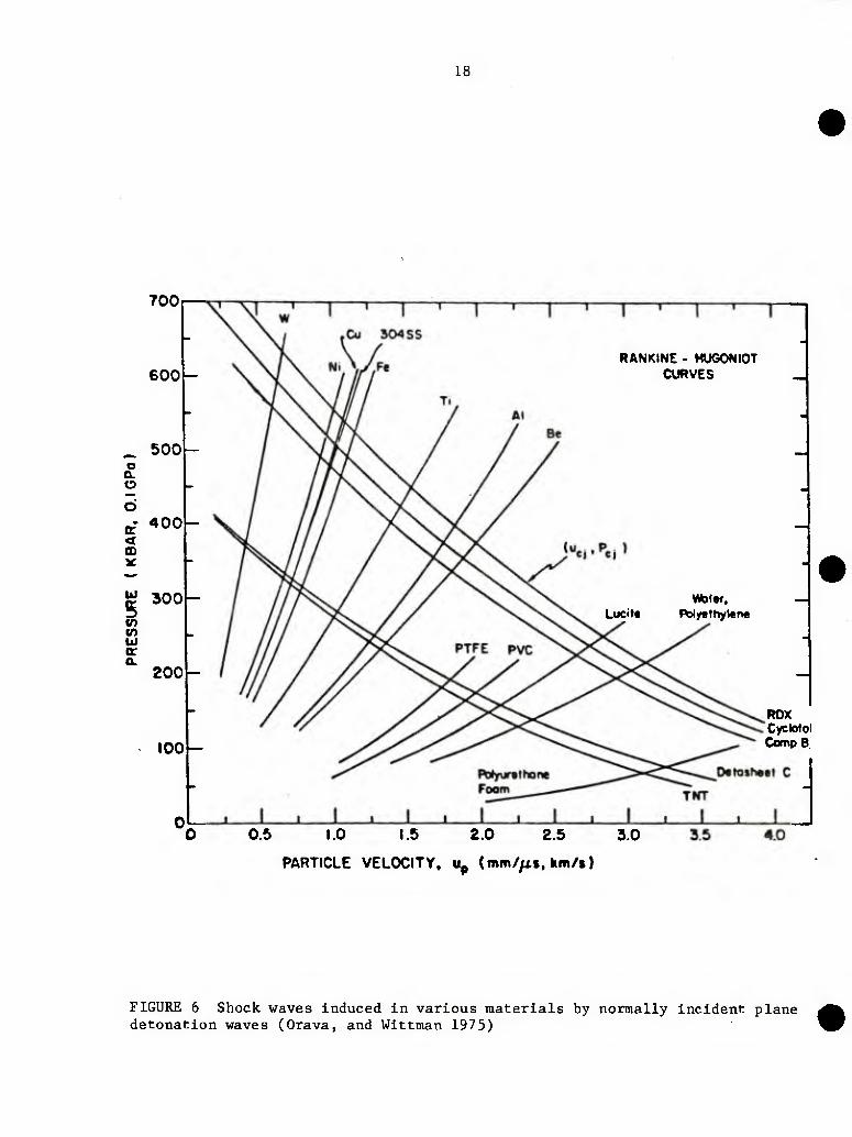
The pressures generated by direct contact explosive operations are a function of the characteristics of the explosive and the material in contact with the explosive. This is Illustrated in Figure 6 where the Hugoniots for a variety of materials are plotted in terms of pressure versus particle velocity and reflection characteristics for several commonly used explosives. The point of intersection of the Hugoniot of the solid with the reflection characteristic of the explosive represents the pressure and particle velocity produced by a contact detonation of normal incidence. The powder usually is encapsulated in a metal container with the explosive being placed in contact with the container. The container therefore modifies the pressure induced in the powder. However, if the Hugoniots and reflection characteristics of the materials (container and powder) involved are known, the pressure generated in the powder can be predicted accurately.
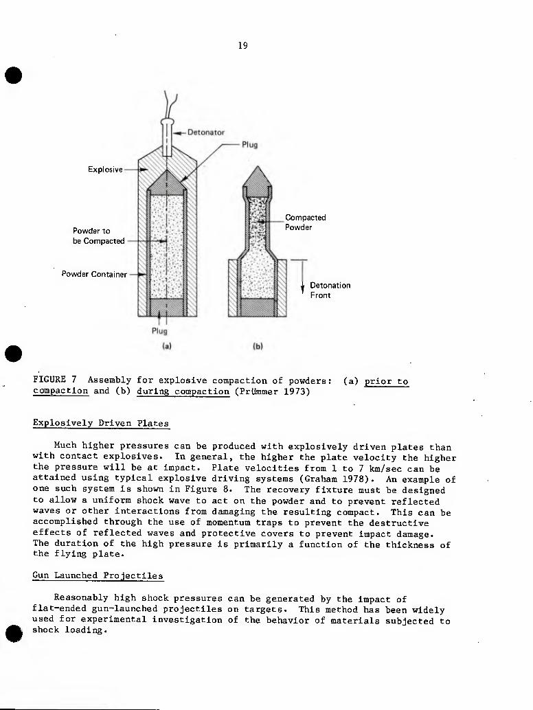
Direct contact explosive compaction usually is employed on either flat plate or cylindrical geometry compacts. In flat plate compacts, the explosive may be positioned on either one or both of the major flat surfaces and detonated either normal to or parallel to the surface. Detonation normal to the surface as opposed to parallel generates considerably higher pressures in the powder. In the cylindrical geometry, the powder is enclosed in a cylindrical metal container surrounded by an explosive, as illustrated in Figure 7 (a), and detonation almost always is parallel to the major axis of the compact. As discussed above, the pressure generated in the powder is a function of the explosive, the container material, and the powder characteristics with the further complication of the velocity of the collapsing tube. This latter factor is a function of the ratio of the explosive mass per unit area to tube mass per unit area. Figure 7 (b) shows the arrangement at some time after detonation during the compaction process.
18
700
600
_ 500 o o. o
CD
UJ
0) kl o: a.
400
300
200
100
RANKINE - HUGONIOT CURVES
Lucits Wycthytene
ROX Cyclotol CompB.
0.5 1.0 1.5 2.0 2.5 3.0
PARTICLE VELOCITY, Up Cmm//i», hm/»)
FIGURE 6 Shock waves induced in various materials by normally incident plane detonation waves (Orava, and Wittman 1975)
19
Explosive
Powder to be Compacted
Powder Container
Compacted Powder
1 Detonation Front
FIGURE 7 Assembly for explosive compaction of powders: compaction and (b) during compaction (Priimmer 1973)
(a) prior to
Explosively Driven Plates
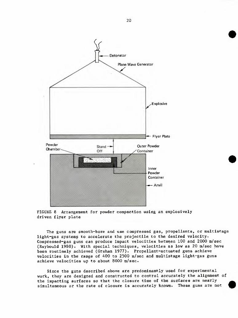
Much higher pressures can be produced with explosively driven plates than with contact explosives. In general, the higher the plate velocity the higher the pressure will be at impact. Plate velocities from 1 to 7 km/sec can be attained using typical explosive driving systems (Graham 1978). An example of one such system is shown in Figure 8. The recovery fixture must be designed to allow a uniform shock wave to act on the powder and to prevent reflected waves or other interactions from damaging the resulting compact. This can be accomplished through the use of momentum traps to prevent the destructive effects of reflected waves and protective covers to prevent impact damage. The duration of the high pressure is primarily a function of the thickness of the flying plate.
Gun Launched Projectiles
Reasonably high shock pressures can be generated by the impact of flat-ended gun-launched projectiles on targets. This method has been widely used for experimental investigation of the behavior of materials subjected to shock loading.
20
Detonator
Plane Wave Generator
Explosive
Flyer Plate
Powder Chamber
Outer Powder
iner
Inner Powder Container
Anvil
FIGURE 8 Arrangement for powder compaction using an explosively driven flyer plate
The guns are smooth-bore and use compressed gas, propellants, or multistage light-gas systems to accelerate the projectile to the desired velocity. Compressed-gas guns can produce impact velocities between 100 and 2000 m/sec (Raybould 1980). With special techniques, velocities as low as 20 m/sec have been routinely achieved (Graham 1977). Propellant-actuated guns achieve velocities in the range of 400 to 2500 m/sec and multistage light-gas guns achieve velocities up to about 8000 m/sec.
Since the guns described above are predominantly used for experimental work, they are designed and constructed to control accurately the alignment of the impacting surfaces so that the closure time of the surfaces are nearly ^^ simultaneous or the rate of closure is accurately known. These guns are not ^^
21
designed for rapid cycling and are therefore not suitable for production work. However, a production machine that launches a projectile using compressed air is under development by Institute CERAC, S.A., of Switzerland (Raybould 1981). The speed range of the projectile is 300 to 1200 m/sec and compaction of the powder occurs by the passage of an intense shock wave through the powder.
Commercial Machines
Several commercial high speed forming machines have been developed that operate on the principle of the sudden release of stored energy (Davies and Austin 1970). The energy is stored in a compressed gas, the sudden expansion of which accelerates a ram. Examples of machines using this principle are those formerly made by Dynapak and U.S. Industries. Other machines use chemically stored energy in the form of a combustible fuel and still others use electrical energy to accelerate the mass directly. An example of a machine using chemically stored energy is the Petro-Forge, which was designed by the Mechanical Engineering Department of England's University of Birmingham. Although these machines were not specifically designed to produce shock waves in materials, some of them have been used for the dynamic compaction of powders. A brief description of the Dynapak, U.S. Industries, and Petro-Forge machines is given below.
The Dynapak machines were produced by the Convair Division of General Dynamics Corporation. Although these machines are no longer manufactured, a number are still in operation. The preferred energy source is dry nitrogen compressed to about 2000 psi. The system is designed such that the high pressure gas holds the piston against a seal, keeping the system in static balance with a large area of the piston exposed to atmospheric pressure. The machine is triggered by a small surge of high pressure gas into the chamber on the atmospheric side of the piston. This admission of gas disturbs the static balance breaking the seal so that the entire external face of the piston is exposed to the high pressure gas. The force exerted by this gas pressure accelerates the piston very rapidly until it strikes the work piece. The design of the machine is such that very little shock is transmitted to the ground. The maximum ram speed of all the machines is about 18 m/sec. The range of maximum energies of the various machines is between 8000 and 225,000 ft-lb; the cycle rate ranges from 20 to 7 cycles per minute.
The U.S. Industries machines are manufactured by its Production Machine Division and use the sudden release of compressed nitrogen to drive opposed rams together. The method of energy release, which is somewhat different than that of the Dynapak machines, will not be described here. These machines are available in three sizes, the maximum energy of the blow being 50,000, 150,000 and 300,000 ft-lb. The maximum closing speed of the platens is about 20 m/sec in each model and a typical cycling rate is 8 per minute.
The Petro-Forge machine works on a principle similar to that of the Dynapak machine with the major exception that the energy is supplied by combustion of a fuel. The pressure thus produced breaks a seal releasing high pressure products of combustion to act over the entire piston area. The piston assembly is thus
22
accelerated rapidly downward. The maximum rating of this machine is 20,000 ft-lbs of work with a maximum impact velocity of 18 m/sec and a cycle time of one per second.
INSTRUMENTING AND MONITORING HIGHLY DYNAMIC EVENTS
As mentioned previously, the measurement of any pair of variables in Equations (1) through (6), when coupled with the known initial conditions, is sufficient to define a point on the shock wave loci or Hugoniot. The most useful representations result from the plotting of P versus u and U versus u. Also, if the equation of state is known, a useful representation in the P versus V plane is obtained. A comprehensive review of the various techniques for measuring wave profiles in shock-loaded solids is given by Graham and Asay (1978). Earlier reviews of methods are given by Fowles (1972), Jones and coworkers (1970), Karnes (1968), McQueen (1964), Doran (1963), Duval and Fowles (1963), and Deal (1962). Because the literature is so extensive, only a brief description of some selected methods will be presented here.
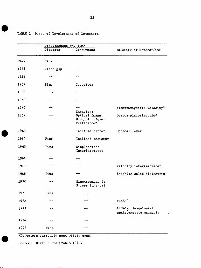
Table 2 presents a history of the most widely used detectors (Davison and Graham 1979). The methods are grouped into two broad categories: those that give a measurement of the displacement as a function of time and those that give a measurement of velocity or stress as a function of time. The displacement versus time devices are further divided into those that produce discrete points (a collection of these would be required to give a series of points on a displacement-time curve) and those that give continous displacement-time measurements. Hence, measurement of shock transit times via back-surface motion and measurement of the free-surface displacement as a function of time permit the determination of the shock velocity, U, and the particle velocity, u, which is approximately the free-surface velocity. The devices used for displacement measurements and stress measurements can be classified as optical, electrical and radiographic. An example of an optical device is a smear or streak camera that can be used to measure both shock and free-surface velocities. An example of an electrical device is a displacement capacitor that can be used to measure free surface velocity.
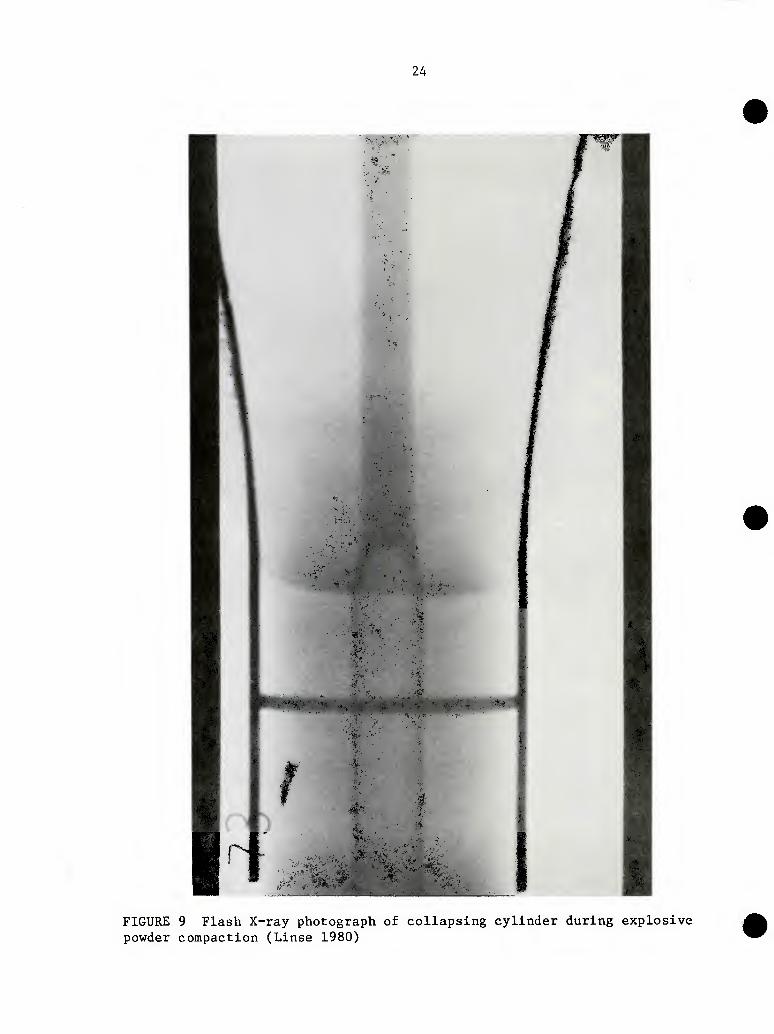
Multiple-flash X-ray photographs at known time intervals can be used to measure directly both shock velocity and density behind a strong shock wave. Flash X-ray techniques also can be used to show a shock profile at some specific time during an event such as that shown in Figure 9. The figure shows a collapsing cylinder during a powder compaction experiment from a starting configuration similar to that shown in Figure 7 (a).
The earliest free-surface displacement measurements were made by setting a large number of electrical contactor pins at carefully measured distances from the surface and recording the shorting times on one or more oscilloscopes. This technique is tedious; however, variations of the method appear from time to time.
23
TABLE 2 Dates of Development of Detectors
Displacement vs. Time Discrete Continuous Velocity or Stress-Time
1945 Pins
1955 Flash gap
1956 —
19 57 Pins
1958 —^
19 59 —
1960 —
1962
1963 —
1964 Pins
1965 Pins
1966 —
1967 —
1968 Pins
1970 —
1971 Pins
1972 —
1973 —
1974 —
1976 Pins
Capacitor
Capacitor Optical image Manganin piezo- resistance^
Inclined mirror
Inclined resistor
Displacement Interferometer
Electromagnetic Stress integral
Electromagnetic velocity^
Quartz piezoelectric^
Optical lever
Velocity interferometer
Sapphire solid dielectric
VISARa
LiNb03 piezoelectric
anxisymmetric magnetic
^Detectors currently most widely used.
Source: Davison and Graham 1979.
24
i
Bfe.
FIGURE 9 Flash X-ray photograph of collapsing cylinder during explosive powder compaction (Linse 1980)
25
The flash-gap uses the principle that gases such as air, argon, or xenon in narrow spaces between a specimen surrounded by plastic blocks are heated to luminescence by successive shock, reverberations in the gas. Subsequent heating of the plastic quickly extinguishes the light. These events can be recorded by a smear camera and hence, knowing the writing speed, the transit time of the shock wave through the specimen can be determined.
The capacitor method uses the specimen as one electrode of a variable condenser wherein the capacitance varies inversely with the spacing. Thus, a circuit is designed such that a voltage varying with capacitor gap is produced and recorded on an oscilloscope.
Optical techniques are based on the fact that the optical reflectivity of the free surface of a solid almost always is considerably reduced during the emergence of a shock wave. Several schemes based on this phenomenon have been used to record data. One such technique uses transparent mirrors silvered on their inside surfaces. The mirror on the specimen-free surface is inclined at a small angle. The assembly is illuminated by an intense light source. The arrival of the shock wave causes an abrupt change in the light intensity. The event is recorded by a streak camera through a viewing slit and gives the velocity of the collision point between the specimen free surface and the inclined mirror. Knowing the collision point velocity and the angle of inclination of the mirror, the free surface velocity can be calculated.
The slant-wire resistor also can be used to record the change in resistance with time as the free surface contacts the wire. The distance versus time curve thus obtained can be differentiated to obtain the free-surface velocity.
Electromagnetic velocity transducers have been used to obtain time-resolved particle velocity measurements in insulators. The method uses a short length of conductor embedded in the material. A voltage is produced that is propor- tional to velocity and an externally applied transverse magnetic field.
Laser interferometry has been used to measure both free-surface displacement and velocity. The technique uses the usual beam-splitting methods and interference fringe analysis.
The original velocity interferometer method required specularly reflecting surfaces. However, if the moving surface is used as a light source for a wide angle Michelson interferometer, a diffusely reflecting surface will do. This resulted in the velocity interferometer system for any reflector (VISAR).
The x-cut quartz transducer uses the linear piezoelectric effect to measure time-resolved stress history up to about 25 kilobars. Materials such as manganese, ytterbium, and carbon are piezoresistive and have been used for time-resolved stress history measurements.
26
Temperature measurements of opaque solids subjected to shock loading have been limited to the surface whereas the internal temperatures of shocked transparent solids have been measured by optical means. Raybould (1980) reports measurement of the average temperature rise in shock powders by means of a thermocouple embedded in the powder.
REFERENCES
Davies, R. and E. R. Austin. 1970. Developments in High Speed Metal Forming. Section 2, 2.1:41-64 and Section 2, 2.5:159-174, Industrial Press.
Davison, L. and R. A. Graham. 1979. Shock Compression of Solids, In Physics Reports 55(4):255-379. North-Holland Publishing Company.
Deal, W. E., Jr. 1962. Dynamic high pressure techniques, In Modern Very High Pressure Techniques, R. H. Wentorf, Jr., Editor. Washington, D.C.: Butterworths.
Doran, G. G. 1962. High Pressure Measurement, pp. 59-86. A. A. Girdini, and E. C. Lloyd, Editors.
Duvall G. E. and G. R. Fowles. 1963. Shock waves. In_ High Pressure Physics and Chemistry, pp. 209-291. Academic Press. R. S. Bradley, Editor.
Fowles, G. R. 1972. Dynamic Compaction of Materials by Intense Impulsive Loading, Air Force Materials Laboratory, Wright-Patterson AFB, Ohio. P. C. Chon and A. K. Hopkins, Editors.
Graham, R. A. and J. R. Asay. 1978. Measurement of wave profiles shock-loaded solids. Ln High Temperatures-High Pressures, 10:355-390.
Graham, R. A. 1977. Second-and third-order piezoelectric stress constants of lithium niobate as determined by the impact-loading technique. Journal of Applied Physics 48:2153-2163.
Graham, R. A. 1977. Techniques for measurements of plane waves of uniaxial strain. Presented at The Workshop on Nonlinear Waves Sponsored by National Science Foundation and the University of Illinois, Chicago Circle.
Hermann, W. 1969. Constitutive equation for the dynamic compaction of ductile porous materials. Journal of Applied Physics: 40(6):2490-2499.
Jones, A. H., C. J. Maiden, and W. M. Isabell. 1970. Mechanical Behavior of Materials Under Pressure, pp. 680-747. Elsevier Publishing Company Ltd., London. H. L. D. Pugh, Editor.
Jones, 0. E. 1972. Metal response under explosive loading, in behavior and
utilization of explosives. In Engineering Design, pp. 125-148.
27
Kafnes, Charles H. 1968. The plate impact configuration for determining mechanical properties of materials at high strain rates. In_ Mechanical Behavior of Materials Under Dynamic Loads. U. S. Lindholm, Editor.
Linse, V. D. 1980. Dynamic compaction of ceramic and metals. Presented at the H. J. Kraner Award Symposium: Innovative Forming Methods in Ceramic and Metals Systems, Lehigh Valley Section of the American Ceramic Society, Bethlehem, Pennsylvania.
McQueen, R. G. 1964. Laboratory techniques for very high pressures and the behavior of metal under dynamic loading. In Metallurgy at High Pressures and High Temperatures, pp. 44-132. K. A. Gschneider, J. F. Hepworth and N. A. Parlee, Editors.
McQueen, R. G., S. P. Marsh, J. W. Taylor, J. N. Fritz, and W. J. Carter. 1970. The equation of state of solids from shock wave studies. In High Velocity Impact Phenomena. Academic Press. Ray Kinslow, Editor.
Orava, R. N. and R. H. Wittman. 197 5. Techniques for the control and application of shock waves. Proceedings of the 5th International Conference on High Energy Rate Fabrication, Denver, Colorado.
Priimmer, Rolf A. 1973. Latest results in the explosive compaction of metal and ceramic powders and their mixtures. Presented at the Fourth International Conference of the Center for High Energy Forming, Vail, Colorado.
Raybould, Derek. 1981. The production of strong parts and non-equilibrium alloys by dynamic compaction. In Shock Waves and High-Strain-Rate Phenomena in Metals. Plenum Press. Mac A. Meyers, and Lawrence E. Muir, Editors.
Rice, M. H., R. G. McQueen, and J. M. Walsh. 1958. Compression of Solids by Strong Shock Waves Solid State Physics, p. 6. Academic Press.
Roman, Gleg V. and V. G. Gorobtsov. 1981. Fundamentals of explosive compaction of powders. Ln Shock Waves and High-Strain-Rate Phenomena in Metals. Plenum Press. Marc A. Meyers and Lawrence E. Muir, Editors.
Roman, 0. V., A. P. Bogdanov, and I. M. Pinkus. 1980. Development of explosive compacting methods in powder metallurgy. Iri^ Explosive Welding and Forming (P. M. Institute, USSR), p. 44. I. Berman, and J. W. Schroeder, Editors.
Roman, 0. V., V. F. Nosterenko, and I. M. Pinkus. 1979. Influence of the powder particle size on the explosive pressing process. Fizika Goreniya i Vzryva 15:102-107.
Chapter 4
CONSOLIDATION AND RELATED PHENOMENA DURING DYNAMIC COMPACTION
MATERIALS RESPONSES
The classical macroscopic approach to dynamic shock wave alteration of a solid is expressed in the Rankine-Hugoniot relationship that includes only one materials parameter, E, an averaged value defined as internal energy per unit mass. In this macroview, the material itself is treated as being homogeneous and possessing continuum properties. In fact, even in solid bodies, the actual processes by which real materials are able to absorb energy are very likely to be discrete, strongly orientation dependent, and quite inhomogeneous. In particulate assemblages, although some statistical averaging takes place, the elementary processes remain locally quite discrete and inhomogeneous.
The externally determined macroscale knowledge of the shock event must be supplemented with very detailed microstructural predictions and/or characterizations of its consequences if a fundamental understanding of the shock-induced compaction process is to be developed, if the process is to be generalized over a wide range of materials choices, or if articles of selected materials are to be produced in reliable, useful forms and shapes. The ultimate goal of the materials scientist therefore must be elucidation of all those elementary, often atomistic processes that might enable a specific particulate assemblage of a given material to respond to the passage of a specific shock wave (i.e., under designated conditions of geometry, temperature, etc.) in ways that will yield a very specific set of altered microstructural features. This important goal is not likely to be achieved easily. On the one hand, the fine spatial scale and highly randomized nature of particulate assemblages and, on the other, the very short duration and extreme severity of the typical shock wave event combine to make direct, real time experimentation in this field both quite difficult and inherently limited in terms of useful resolving power. It seems most likely that the needed understanding may have to be gained more indirectly or obliquely, in part through extensive (and expensive) microstructural (and other) characterizations of materials, both before and after shocking, and in part by computer modeling and/or simulation methods.
Itethematical expressions capable of treating the whole set of materials parameters involved in dynamic compaction events apparently have yet to evolve. However, there are enough parallels with various well documented materials
29
30
responses in more conventional rate regimes that place great emphasis on the importance of such things as orientation-dependent tensor properties, morphology-dependent densification processes, detailed materials characterizations, statistical distribution functions, and computer modeling and simulation techniques to warrant preliminary consideration of the probable nature of the most important materials variables.
DESCRIBING ELEMENTARY PROCESSES IN DYNAMIC COMPACTION OF POWDERS
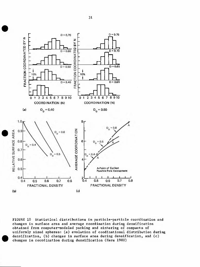
The inherently statistical nature of powders and powder compacts clearly dictates (Palmour et al. 1981) that all the relevant particulate parameters ultimately must be treated as distribution functions (Figure 10).
1. Particle size distribution (not just particle size). 2. Particle shape distribution (not just shape factor). 3. Particle coordination distribution (not just average coordination
number). 4. Orientation vector distrlbution(s) (not just single valued
orientation) including: (a) orientation of stress (or shock wave) vector(s) with respect to
crystallographic orientation vectors within the particle. (b) orientation of stress (or shock wave) vector(s) with respect to
each of the contact points with other particles. (c) location and orientation distributions of other, near-contact
points within the particle assembly.
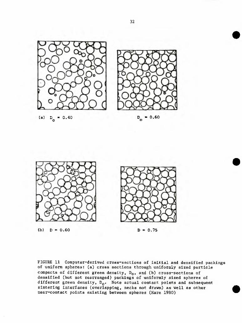
For a given shock wave interacting with a given particle assemblage, the passage of the shock wave(s)—through the mass of particles by means of existing contact points and high probability near-contact points as well (Figure 11)—will be sensitive to the position and orientation distributions described above.
In principle, the materials-dependent consequences of that shock wave passage (e.g., rearrangement, dislocation slip and/or climb, twinning, fracture, communication, melting, jetting) will thereafter be discernable in a before-and-after comparison between the previously characterized initial state and a post-shock characterization of the compacted powder assemblage in the form of similar distribution functions.
The passage of a given shock wave (including multiple arrivals, reflections, departures, etc.) through a given particle or set of particles can be treated with rigor only if all the statistical distributions listed above (and perhaps still others not yet listed) somehow can be measured, defined, and/or estimated.
31
> \- m
I- <
Q CC
O O O z o
o < CC
^_dl] D = 0.70
tbL. >-
D = 0.40 ^
EiHiL 01 23456789 10
COORDINATION (N)
(a) DQ = 0.40
D = 0.75
^^~ ^
_r
D = 0.70
1, ~io% p
D = 0.65
n—1 D = 0.60
-.^ -T_
01 23456789 10
COORDINATION (N)
DQ = 0.60
8r
0.5 0.6 0.7
FRACTIONAL DENSITY
0.8
O I- < ? 6 Q CC
o O O LU
'i 4 CC LU
> < y- A-Point of Earliest
Possible Pore Entrapment
I I _L _L J I 0.4 0.5 0.6 0.7 0.8
FRACTIONAL DENSITY
(b) (c)
FIGURE 10 Statistical distributions in particle-particle coordination and changes in surface area and average coordination during densification obtained from computer-modeled packing and sintering of compacts of uniformly sized spheres: (a) evolution of coodinational distribution during densification, (b) changes in surface area during densification, and (c) changes in coordination during densification (Hare 1980)
32
(a) D = 0.40 o
D = 0.60 o
(b) D = 0.60 0.75
FIGURE 11 Computer-derived cross-sections of initial and densified packings of uniform spheres: (a) cross sections through uniformly sized particle compacts of different green density, DQ, and (b) cross-sections of densified (but not rearranged) packings of uniformly sized spheres of different green density, DQ. Note actual contact points and subsequent sintering interfaces (overlapping, necks not drawn) as well as other near-contact points existing between spheres (Hare 1980)
33
For almost all ceramics, and probatly for most metals, the local concentrations of compressive stress at contact points during dynamic compaction give rise to large hydrostatic restraining forces that permit extensive plastic flow processes to occur locally at strain rates far higher than could be tolerated by that material under normal static loading conditions.
Local temperature gradients and distributions may be extreme, and at least in part, will depend on all the statistical and spatial distributions described above.
The microstructural consequences of the shock wave through such a particle assemblage will depend sensitively on the nature of the material, the scale of the experiment, other imposed conditions, and the basic parameters of the shock, wave itself as well as on the statistical distribution factors. For most materials, the consequences hopefully can be described in terms of a statistically definable distribution of bond types and/or morphological features resulting from all operable flow and fracture mechanisms within a statistically definable spatial distribution.
For the dynamic compaction of powders, this whole ensemble of highly variable conditions, distributions, and other factors constitutes a very formidable set of physical and mathematical obstacles, a set clearly capable of challenging the best theoreticians, modelers, experimenters, and characterizers for years to come. In the rather closely allied, although probably less complex, field of sintering, many such theories and models have been developed for various parts of the whole densification process. In fact, they alone generally have proven to be inadequate for making reliable predictions of actual sintering behavior from first principles (Exner et al. 1973, Exner and Petzow, 1980, Johnson 1973, 1978 and 1980, Palmour et al. 1969). By analogy, and particularly in view of its greater complexity, models and theories for dynamic compaction might well be expected to be similarly inadequate as de facto predictors of exact behavior.
However, any such argument based on direct practical applicability alone is an obviously spurious one. In the committee's view, it certainly does not lead convincingly to the negative position that such theories and models could hardly be worth developing. Rather, the relevant field of sintering has provided many examples of the great value that innovative experimentalists (working sucessfully in complex ceramics, for example) have attributed to enlightenment and guidance they have gained from the available (although admittedly somewhat simplistic) models and theories (Davidge 1973, Kolar 1980, Kolar and Stadler 1978, Palmour and Huckabee 1978, Palmour et al. 1979, Reeve 1966, Spriggs and Dutta 1973, Stuijts 1973).
The emerging field of dynamic compaction of technologically useful particulates obviously needs the early benefit of better theories, more sophisticated models, and more extensive (and much more enlightened) experimentation. Theory, invention, characterization, and reduction to practice are all required, and to be effectively developed in a timely and coordinated way, the field must receive sufficient support to allow all four
34
aspects to develop, and to be sustained interactively and iteratively, in a harmonious and mutually supportive manner.
RECRYSTALLIZATION AND GRAIN GROWTH PHENOMENA DURING DYNAMIC COMPACTION
In contrast to the traditional solids processing methods, in dynamic compaction a high stress is applied for a short period of time and stress relaxation may be achieved during or shortly after compaction by recovery, recrystallization, and growth. Similarly, when metals or ceramics are deformed by more conventional processing methods and heat treated, they also will restore to a stress-free condition by the same mechanisms. In this latter case, however, unless the material is rather well worked, it is likely that stress relaxation will be achieved largely through recovery (dislocation rearrangement and vacancy removal) and secondary grain growth processes. Highly dynamic compaction, however, can lead to a high degree of recrystallization (nucleation and growth process yielding strain-free grains with high angle grain boundaries sweeping through the deformed material). The driving force for both recovery and recrystallization is provided by the high internal energy of the deformed structures, but the energy released by recovery is about ten times smaller than that by recrystallization. Property changes resulting from recovery usually are less significant than those resulting from recrystallization and the energy restored by recovery also is small compared to the high energy input during dynamic compaction. The grain growth process to reduce the interfacial energy becomes operative when recrystallization is completed but it is doubtful that the latter process can be completed within the relatively short time span of dynamic compaction. However, factors other than the driving force, also are applicable to the growth process in recrystallized high-angle grain boundaries. These important factors in dynamic compaction include:
1. Changes in particle characteristics by recrystallization. 2. Effects of stress magnitudes. 3. Effects of deformation modes. 4. Effects of dopants.
Since the stress distribution can be rather heterogeneous within a specimen under compaction, it is conceivable that recrystallization may occur in certain highly strained portions well before densification is completed. Grain boundary migration during recrystallization may lead to the coalescence of several grains and particle coarsening results. Since the driving force for grain boundary motion is rather high and the pore mobility is relatively low at low temperatures, pore entrapment within the coalesced grains can occur. Consequently, recrystallization in a local region of a porous compact can change the powder characteristics and the green microstructure before densification takes place. Another more important change in the powder characteristics during compaction probably results from the frictional force between particles during the stress-imposed particle rearrangement within the compact.
35
It is obvious that the rate of recrystallization depends on the extent of deformation because the driving force due to the high Internal energy Is provided by the deformation process and the nucleatlon and growth processes of the recrystalllzed grain are related to the distribution of dislocation density within the deformed solid. The propensity for recrystallization generally is described by the recrystallization limit (i.e., the minimum temperature below which recrystallization will not occur within a given time). In general, an Increase in strain decreases the recrystallization limit. During dynamic compaction a very high strain can be expected. Therefore, even If the specimen under compaction is maintained at ambient temperature, in-situ recrystallization can occur. Adiabatlc heating during compaction further promotes the recrystallization process.
During recrystallization, the driving force for strain-induced grain boundary migration is due to the difference in the strain energies on both sides of the migrating boundary. Thus, the driving force for boundary migration in a specimen under a hydrostatic stress is Identical to that when the specimen is in an unstressed state. However, some minor difference in the boundary mobility may be expected in a specimen under stress. This is likely due to changes in the solute dlffusivlty, grain boundary structures, and grain boundary energy when a sample is under stress.
The difference in the strain dependences of the nucleatlon rate and the growth rate during recrystallization will be reflected in the resulting microstructure. The nucleatlon rate usually is slow at low strains, but it increases significantly as strain increases. The growth rate, however. Increases rapidly at low strains and becomes constant for strains higher than a certain value. During dynamic compaction, the nucleatlon rate increases rapidly at high strains. Thus, the high-angle, crystallized grain boundaries have to migrate only a short distance before impingement on each other and a fine recrystalllzed microstructure results. However, a heterogeneous strain distribution within a porous compact may be expected. In regions with low strains, the nucleatlon rate may be slow while the growth rate is relatively fast and the grain boundaries may have to migrate a long distance before the Impingement and grain coarsening stops. Consequently, the resulting grain size distribution can be directly related to the heterogeneous strain distribution in a material under compaction.
Recrystallization rates have been found to be dependent on deformation modes. Barto and Ebert (1943) have shown that the recrystallization rate increases as the tensile component of a deformation stress Increases and that the recrystalllzed grain size resulting from tension is significantly larger than that from compression. The tensile component probably increases the dislocation density that provides a greater driving force and a larger number of nucleatlon sites for recrystallization. During dynamic compaction, when the mechanical impedance of the specimen does not match that of the base or substrate, the reflected wave can generate a tensile stress component in a local region of the specimen. Thus, a variation in the resulting microstructure of the specimen may be expected when substrates or bases with different mechanical characteristics are used.
36
A rapid deformation rate has been shown to give rapid multiplication of dislocations and heterogeneous plastic flow. A decrease in the flow stress has been reported at high strain rates. Thus, the high deformation rate during dynamic compaction leads to a greater propensity for recrystallization because of an increased dislocation density. Heterogeneous plastic flow can further increase the variation in the size distribution of the resultant micro structure s.
The rate of recrystallization also has been shown to be strongly dependent on dopant content. In general, a dopant can reduce the recrystallization rate significantly and can increase the minimum strain and temperature required for recrystallization. It has been reported that recrystallization of high purity aluminum (Demmler 1956) and potassium chloride (Yan et al. 1975) can occur at room temperature. However, the solubilities of dopants in both metals and ceramics usually have a strong temperature dependence. When the compaction process is initiated at room temperature, dopants may exist in the form of a supersaturated solid solution or second-phase precipitates, depending on the thermal history of the powder preparation process. Adiabatic heating during compaction may lead to either a further precipitation or particle coalescence on dissolution of the second phase into the matrix, depending on the kinetics as well as the degree of departure from equilibrium at the compaction temperature. It is obvious that the thermodynamic state of dopants during dynamic compaction can have a profound influence on the recrystallization process. Consequently, the recrystallization kinetics and mechanisms may vary significantly depending on the type and amount of dopants as well as the thermal history of the powder and the compaction conditions.
A solute may affect both the nucleation and growth stages during recrystallization. It generally is believed that both the nucleation and growth rates are decreased, but probably at different rates, by a solute. It has been proposed that solutes stabilize dislocation networks or low-angle grain boundaries so that their coalescence to form nuclei for recrystallization is delayed. Solutes also can decrease the overall misorientation across sub-cell walls and, thus, decrease the nucleation rate. A reduction in the stacking-fault energy can be caused by solutes, and this can influence the perfection and size of sub-cells.
There have been several theories of grain growth inhibition by solute drag (e.g., by Cahn, Lucke, and Stuve). These theories essentially assume an interaction potential between an impurity cloud and the migrating grain boundary. An asymmetric solute distribution on both sides of the migrating grain boundary leads to an impurity drag force. When the migration rate of the grain boundary is sufficiently fast, the solute diffusion cannot keep pace with the boundary and a break-away of the solute cloud occurs. This may lead to a change in the controlling mechanism in grain boundary migration kinetics.
Kreye and Hornbogen (1970) have reviewed the recrystallization process in a supersaturated solution. The incubation times for the recrystallization and precipitation processes are analyzed and shown in Figure 12. When the strain is relatively high, tj., the incubation times for recrystallization are much
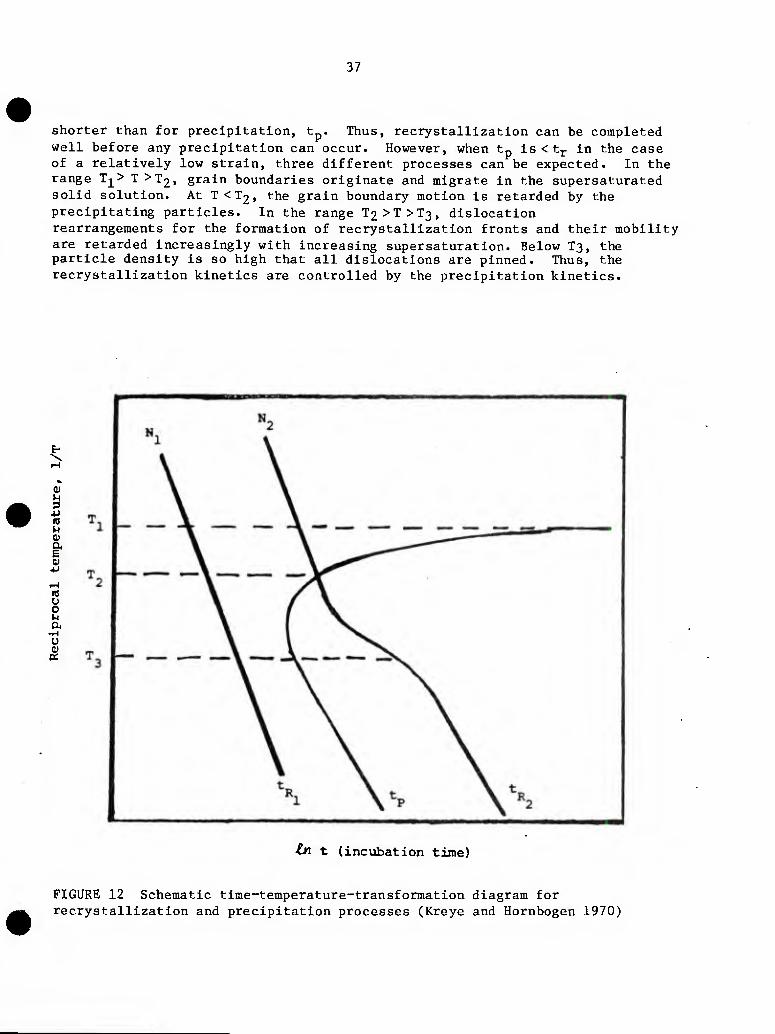
37
shorter than for precipitation, t . Thus, recrystallization can be completed well before any precipitation can occur. However, when tp is < tj- in the case of a relatively low strain, three different processes can be expected. In the range T-|^> T >T2, grain boundaries originate and migrate in the supersaturated solid solution. At T <T2, the grain boundary motion is retarded by the precipitating particles. In the range T2>T>T3, dislocation rearrangements for the formation of recrystallization fronts and their mobility are retarded Increasingly with increasing supersaturation. Below T3, the particle density is so high that all dislocations are pinned. Thus, the recrystallization kinetics are controlled by the precipitation kinetics.
4-1
a; a E 01
u a u 0)
tn t (incubation time)
FIGURE 12 Schematic time-temperature-transformation diagram for recrystallization and precipitation processes (Kreye and Hornbogen 1970)
38
The most important attributes of the second phase affecting recrystallization in two-phase alloys are the particle size, the volume fraction, and the interparticle spacing. Recrystallization can be either accelerated or retarded by the presence of dispersed second-phase particles. In general, acceleration is associated with coarse particles and wide interparticle spacings. It generally is believed that widely spaced, coarse particles create localized strain concentrations at particle-matrix interfaces and enhance the dislocation cell formation for recyrstallization nuclei. However, retardation in recrystallization is usually reported in cases with fine particles and close interparticle spacings. The closely spaced, fine particles lead to a more uniform dislocation distribution with a less pronounced cell structure required to initiate recrystallization.
It is obvious that the characteristics of the powder used for dynamic compaction can affect the particle size and the interparticle spacing. Available techniques in ceramic processing and powder metallurgy can be employed to tailor the powder characteristics so that the desired recrystallization behavior can be achieved during dynamic compaction.
REFERENCES
Barto, R. L. and L. J. Ebert. 1971. Met. Trans. 2:1643.
Davidge, R. W. 1973. In_ Science of Ceramics, Deut. Keram. Gessellschaft, p. 6.
Demmler, A. W. 1956. Met. Soc. 206:958.
Exner, H. E., G. Petzow, and P. Wellner. 1973. Problems in the extension of sintering theories to real systems. Tn Sintering and Related Phenomena, Materials Science Research: 6. Plenum Press. G. C. Kuczynski, Editor.
Hare, T. M. Statistics of early rearrangement by computer simulation, In_ Sintering Processes. Materials Science Research 13:77-93. Plenum Press. G. C. Kuczynski, Editor.
Johnson, D. L. 1973. Interpretation of sintering kinetics data. In_ Sintering and Related Phenomena, Materials Science Research, p. 16. Plenum Press. G. C. Kuczynski, Editor.
39
Johnson, D. L. 197 8. Fundamentals of the sintering of ceramics. In Processing of Crystalline Ceramics, Materials Science Research: 11. Plenum Press. H. Palmour, R. F. Davis, and T. M. Hare, Editors.
Johnson, D. L. 1980. Solid state sintering models. In Sintering Processes, Materials Science Research, p. 13. Plenum Press. G. C. Kuczynski, Editor.
Kolar, D. 1980. On the role of sintering research in ceramic engineering. In Sintering Processes, Materials Science Research, p. 13. Plenum Press. G. C. Kuczynski, Editor.
Kolar, D. and Z. Stadler. 1978. Sintering in multicomponent systems. Proceedings of the International Symposium on Factors in Densification and Sintering of Oxide and Nonoxide Ceramics. Tokyo, Japan. S. Somiya and S. Saito, Editors.
Kreye, H. and E. Hornbogen. 1970. Journal of Materials Science 5:89.
Palmour, H., R. A. Bradley, and D. R. Johnson. 1969. A reconsideration of stress and other factors in the kinetics of densification, jLn Kinetics of Reaction in Ionic Solids, Materials Science Research, p. 4. Plenum Press. T. J. Gray and V. D. Frechette, Editors.
Palmour H. and M. L. Huckabee. 1978. Rate controlled sintering. In Proceedings of the International Symposium on Factors in Densification and Sintering of Oxide and Nonoxide Ceramics, Tokyo Institute of Technology, Tokyo, Japan. S. Somiya and S. Saito, Editors.
Reeve, K. D. 1966. Control of microstructure in single phase oxide ceramics. Journal of the Australian Ceramic Society 2:38-46.
Roman, 0. V., A. P. Bogdanov, and I. M. Pinkus. 1980. Development of explosive compacting methods in powder metallurgy. P. M. Institute (USSR), In Explosive Welding and Forming: 44. I. Bermann and J. W. Schroeder, ASME, Editors.
Roman, 0. V., V. G. Gorobtsov. 1981. Fundamentals of explosive compaction of powders, In^ Shock Waves and High-Strain-Rate Phenomena in Metals, pp. 829-842. Plenum Press. M. A. Meyers and L. E. Muir, Editors.
Spriggs, R. M. and S. K. Dutta. 1973. Mechanisms of sintering during hot pressing and recent technological advances, Ln Sintering and Related Phenomena, Materials Science Research, p. 6. Plenum Press. G. C. Kuczynski, Editor.
Stuijts, A. L. 1973. Sintering theories and industrial practice, In_ Sintering and Related Phenomena, Materials Science Research, p. 6. Plenum Press. G. C. Kuczynski, Editor.
Chapter 5
DYNAMIC COMPACTION AND CONDITIONING OF METAL AND CERAMIC POWDERS
HISTORICAL BACKGROUND
Research on the dynamic compaction of metal and ceramic powders had Its experimental beginnings primarily In the United States in the 1950s and 1960s (Bergmann 1966, Bergmann and Barrington 1966, Carlson et al. 1966, McKenna et al. 1955). Subsequently, research interest in (and/or support of) the dynamic compaction of powders tended to diminish in the United States but spread worldwide, and by 1973 substantial contributions to the scientific and technological literature in this growing field were originating in West Germany and the Soviet Union (Bogdanov et al. 1973, Kuz'min and Staver 1973, Prlimmer 1973, Samsonov et al. 1973) with additional activity in Japan and elsewhere.
COMPLEXITY-SPECIFICATION
From the scientific and technological viewpoints, the overall topic of dynamic compaction of powders is both complex and very multifaceted. Considered in retrospect, it becomes evident that the field has been developed by using the combined interests and talents of a worldwide, distinctly multidisciplinary group of scientists and engineers. Obviously not all of them have shared all common interests or certainly not all to the same degree. It is not surprising, therefore, to find considerable evidence in the literature of discipline-oriented specialization; this is true even of otherwise excellent general reviews that have thoroughly treated certain specific aspects of the overall subject matter. Physicists generally have written for other physicists, metallurgists for other metallurgists, etc., but few have addressed the whole field comprehensively.
REVIEWS OF THE STATE-OF-THE-ART
Experimental methods and engineering parameters for achieving dynamic compaction of powders of many sorts have been discussed by Priimmer (1973), Clyens and Johnson (1977), Roman and coworkers (1980), Roman and Gorobtsov (1981). The fundamental physics of shock-waves and shock-induced deformation processes have been reviewed by Davison and Graham (1979) and Grady (1980). Lin and Nadiv (1979) have reviewed a variety of mechanical and mechanochemical transformations known to occur during comminution processes and have pointed out the similarity between shock-induced phenomena and those that occur in
i 41
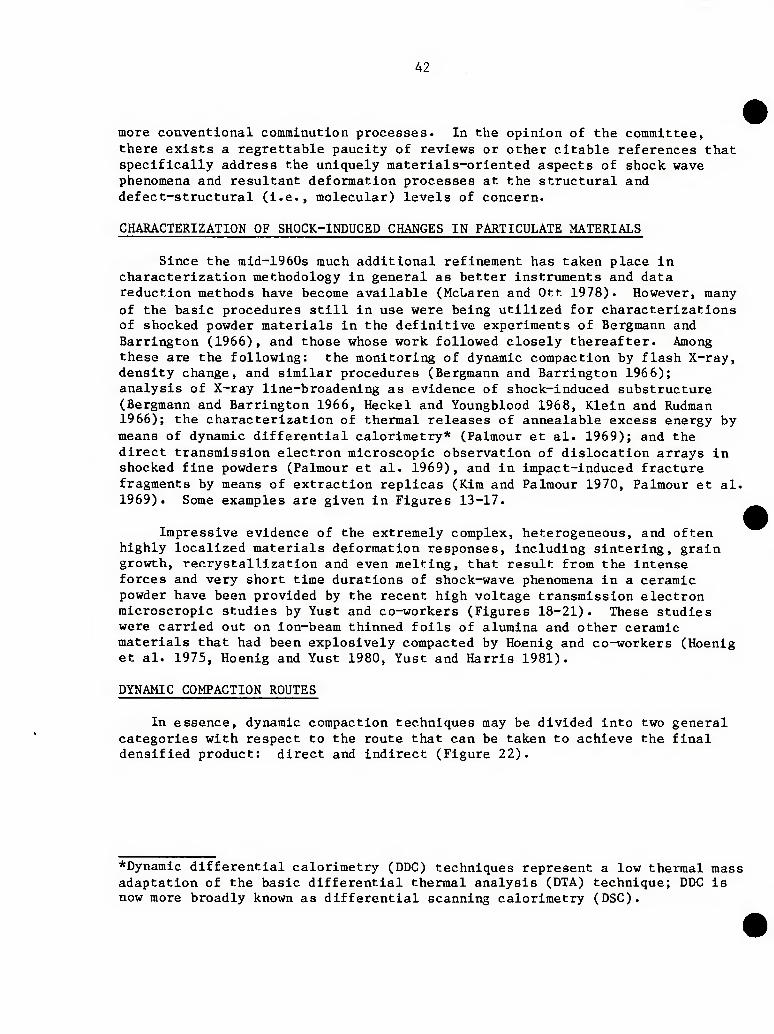
42
more conventional comminution processes. In the opinion of the committee, there exists a regrettable paucity of reviews or other citable references that specifically address the uniquely materials-oriented aspects of shock wave phenomena and resultant deformation processes at the structural and defect-structural (i.e., molecular) levels of concern.
CHARACTERIZATION OF SHOCK-INDUCED CHANGES IN PARTICULATE MATERIALS
Since the mid-1960s much additional refinement has taken place in characterization methodology in general as better instruments and data reduction methods have become available (McLaren and Ott 1978). However, many of the basic procedures still in use were being utilized for characterizations of shocked powder materials in the definitive experiments of Bergmann and Harrington (1966), and those whose work followed closely thereafter. Among these are the following: the monitoring of dynamic compaction by flash X-ray, density change, and similar procedures (Bergmann and Barrington 196 6); analysis of X-ray line-broadening as evidence of shock-induced substructure (Bergmann and Barrington 1966, Heckel and Youngblood 1968, Klein and Rudman 1966); the characterization of thermal releases of annealable excess energy by means of dynamic differential calorimetry* (Palmour et al. 1969); and the direct transmission electron microscopic observation of dislocation arrays in shocked fine powders (Palmour et al. 1969), and in impact-induced fracture fragments by means of extraction replicas (Kim and Palmour 1970, Palmour et al. 1969). Some examples are given in Figures 13-17.
Impressive evidence of the extremely complex, heterogeneous, and often highly localized materials deformation responses, including sintering, grain growth, recrystallization and even melting, that result from the intense forces and very short time durations of shock-wave phenomena in a ceramic powder have been provided by the recent high voltage transmission electron microscropic studies by Yust and co-workers (Figures 18-21). These studies were carried out on ion-beam thinned foils of alumina and other ceramic materials that had been explosively compacted by Hoenig and co-workers (Hoenig et al. 1975, Hoenig and Yust 1980, Yust and Harris 1981).
DYNAMIC COMPACTION ROUTES
In essence, dynamic compaction techniques may be divided into two general categories with respect to the route that can be taken to achieve the final densified product: direct and indirect (Figure 22).
*Dynamic differential calorimetry (DDC) techniques represent a low thermal mass adaptation of the basic differential thermal analysis (DTA) technique; DDC is now more broadly known as differential scanning calorimetry (DSC).
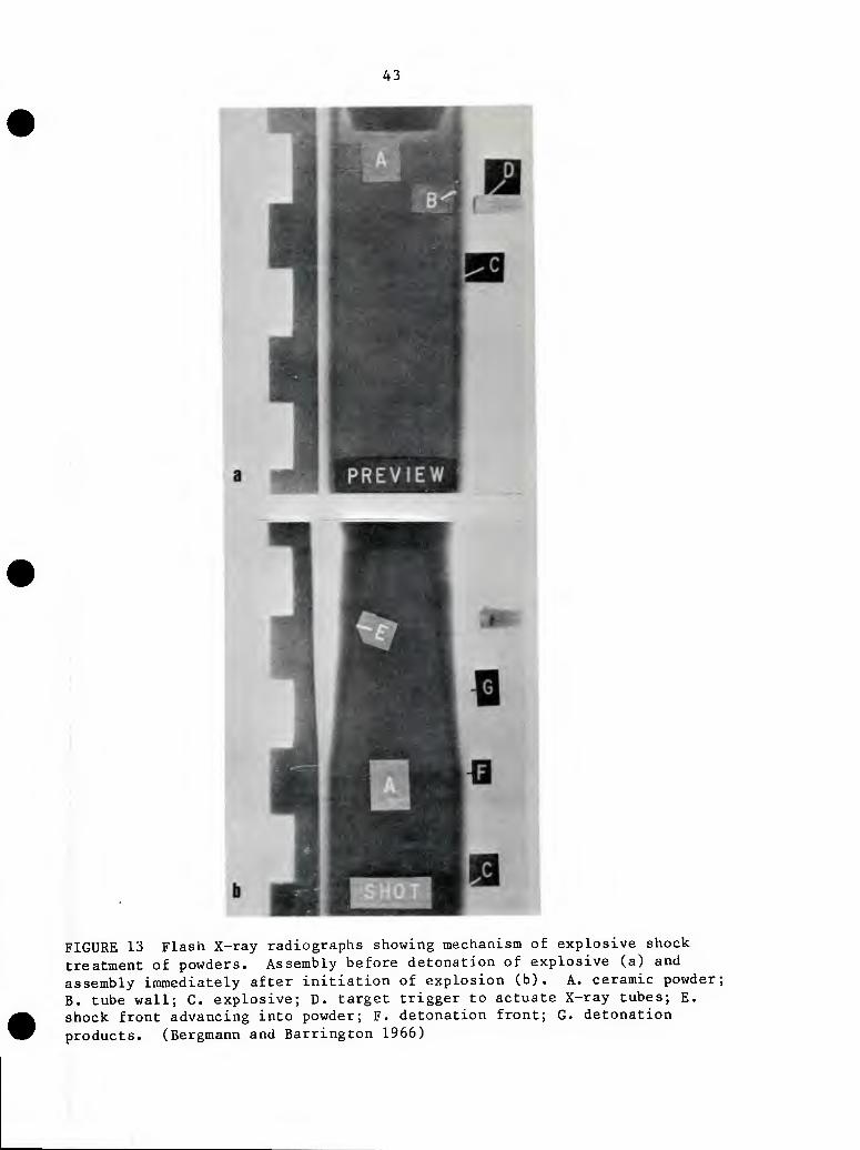
43
FIGURE 13 Flash X-ray radiographs showing mechanism of explosive shock treatment of powders. Assembly before detonation of explosive (a) and assembly immediately after initiation of explosion (b). A. ceramic powder; B. tube wall; C. explosive; D. target trigger to actuate X-ray tubes; E. shock front advancing into powder; F. detonation front; G. detonation products. (Bergmann and Barrington 1966)
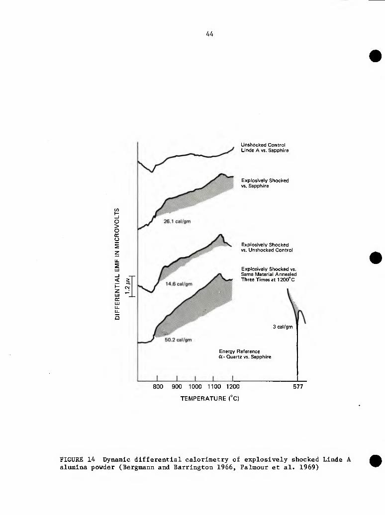
44
w H _l o > o o
< > — 3.
LLI
Unshocked Control Linde A vs. Sapphire
Explosively Shocked vs. Sapphire
Explosively Shocked vs. Unshocked Control
Explosively Shocked vs. Same Material Annealed Three Times at 1200°C
3 cal/gm
Energy Reference Oi- Quartz vs. Sapphire
800 900 1000 1100 1200
TEMPERATURE (°C)
577
FIGURE 14 Dynamic differential calorimetry of explosively shocked Linde A alumina powder (Bergmann and Harrington 1966, Palmour et al. 1969)
45
0.50 r-
0 10 20 30 40 50
GRAMS OF EXPLOSIVE/IN^ OF TUBE SURFACE
FIGURE 15 Line broadening 3 as a function of amount of explosive. Data plotted for diffraction peaks noted in parentheses (hlk.)* Explosive shocking tube diameter = 1-1/8 inch (Bergmann and Harrington 1966)
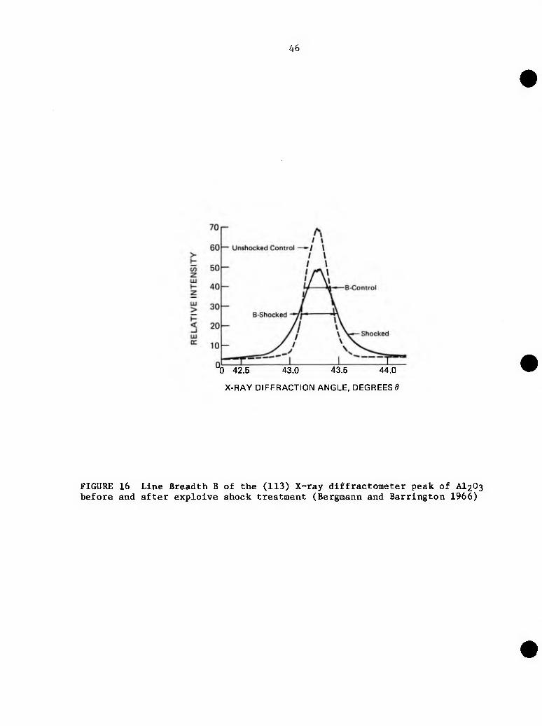
46
"0 42.5 43.0 43.5 44.0
X-RAY DIFFRACTION ANGLE, DEGREES^
FIGURE 16 Line Breadth B of the (113) X-ray diffractometer peak of AI2O3 before and after explolve shock treatment (Bergmann and Barrington 1966)
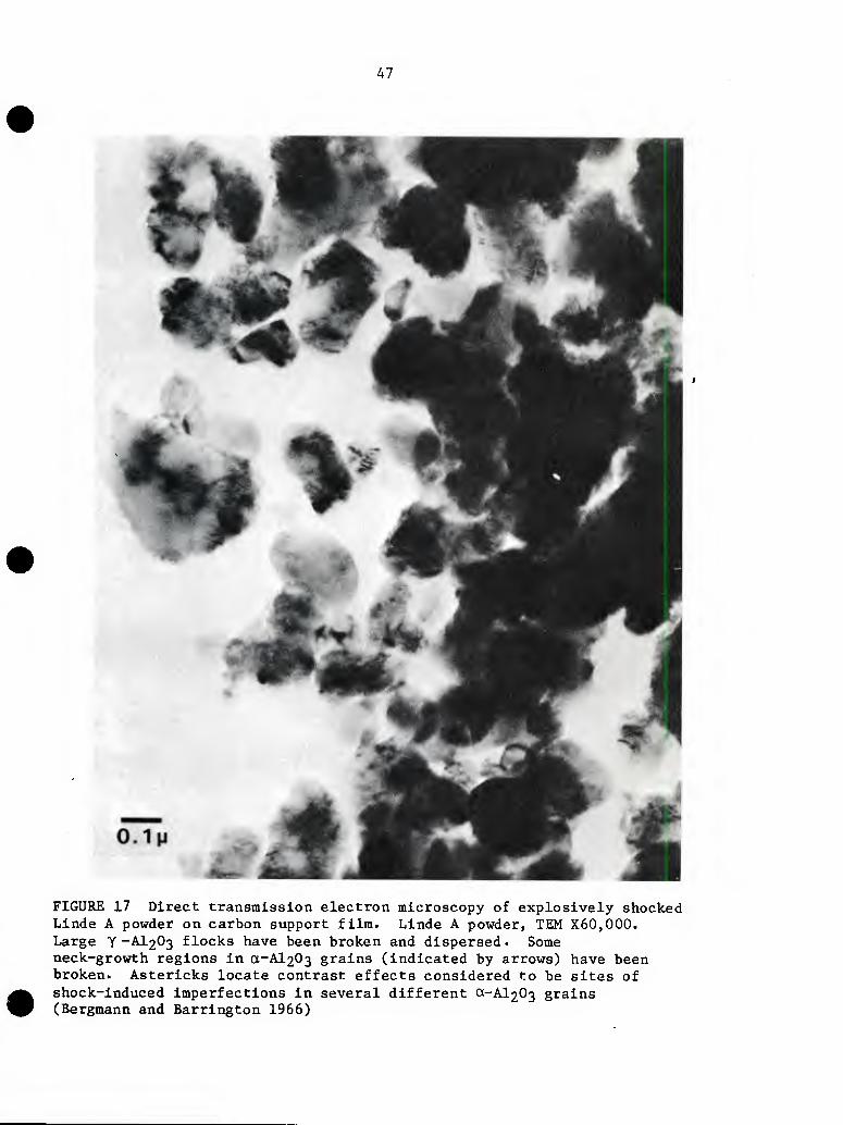
A7
FIGURE 17 Direct transmission electron microscopy of explosively shocked Linde A powder on carbon support film. Linde A powder, TEM X60,000. Large Y -AI2O3 flocks have been broken and dispersed. Some neck-growth regions in a-Al203 grains (indicated by arrows) have been broken. Astericks locate contrast effects considered to be sites of shock-induced imperfections in several different 0(,-Al203 grains (Bergmann and Harrington 1966)

48
FIGURE 18 Extensive plastic deformation In dynamically compacted alumina. Intense tangles of dislocations are visible within the individual grains, whose typical diameters will correspond to those of the starting material. Also note some local evidences of grain boundary sliding (displaced triple points), and cracking (Yust 1980)
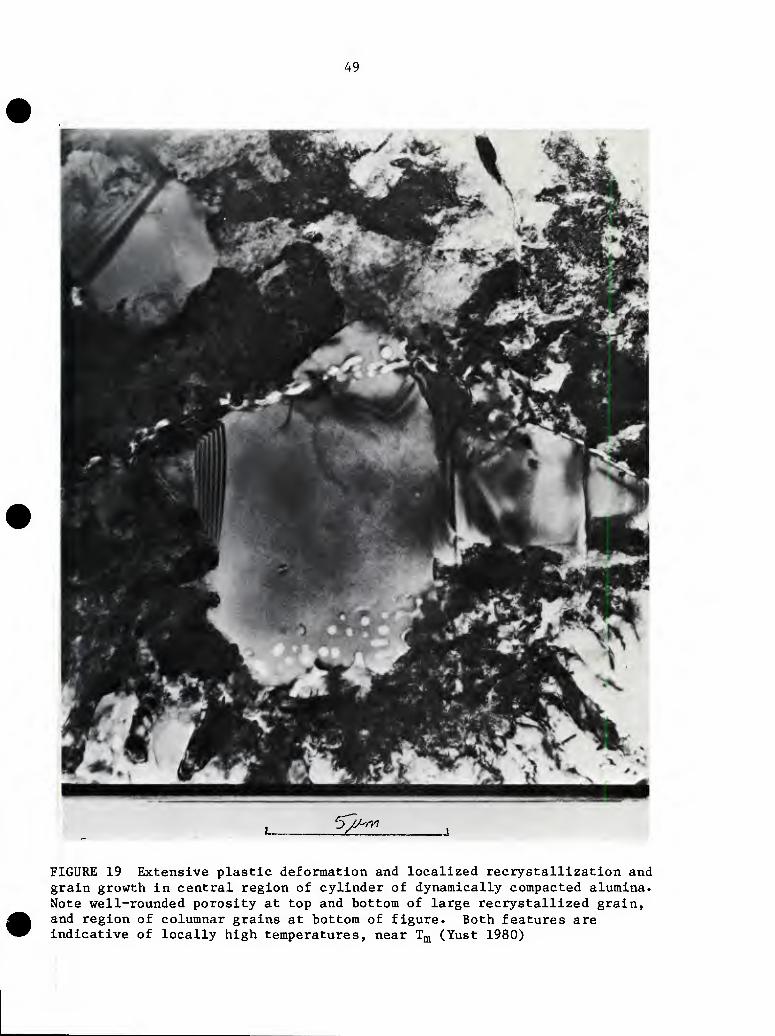
49
'-J/J-rA
FIGURE 19 Extensive plastic deformation and localized recrystallization and grain growth in central region of cylinder of dynamically compacted alumina. Note well-rounded porosity at top and bottom of large recrystallized grain, and region of columnar grains at bottom of figure. Both features are indicative of locally high temperatures, near T^ (Yust 1980)
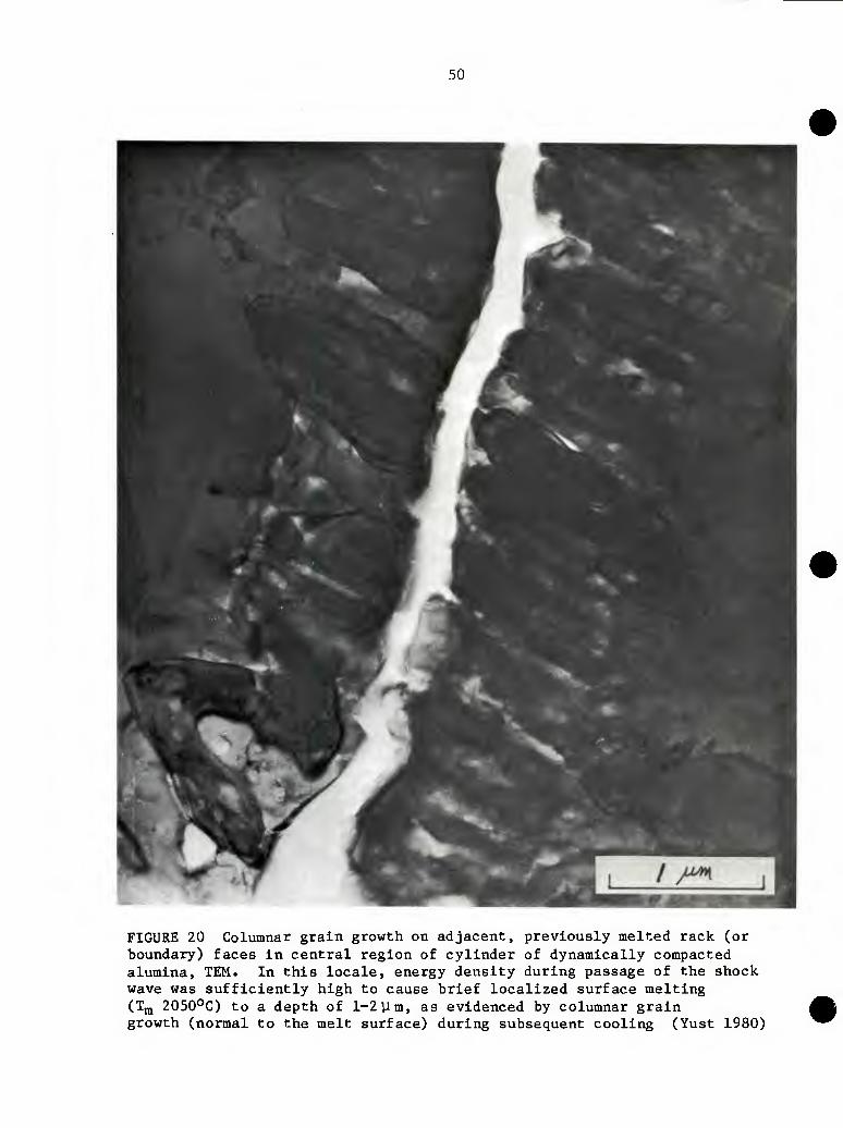
50
FIGURE 20 Columnar grain growth on adjacent, previously melted rack (or boundary) faces in central region of cylinder of dynamically compacted alumina, TEM. In this locale, energy density during passage of the shock wave was sufficiently high to cause brief localized surface melting (TjQ 2050°C) to a depth of 1-2 ym, as evidenced by columnar grain growth (normal to the melt surface) during subsequent cooling (Yust 1980)
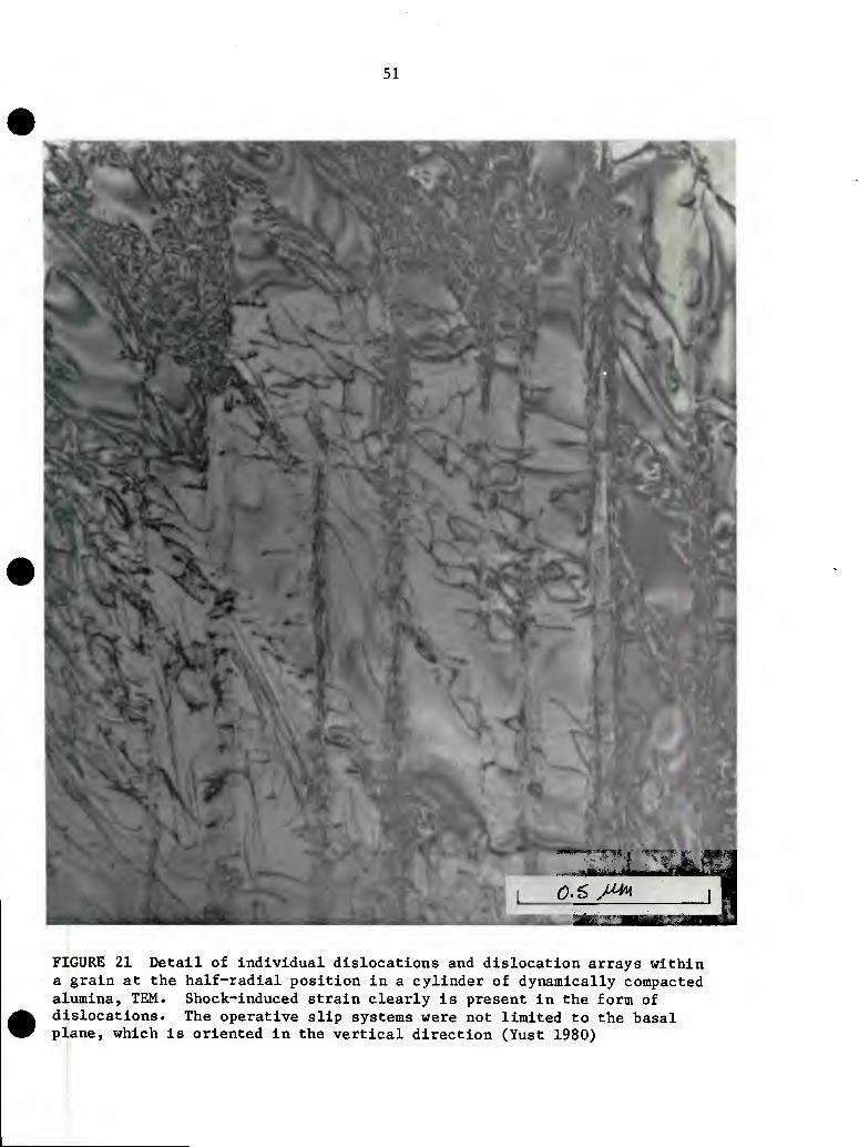
51
<P.S yMt\ J H
FIGURE 21 Detail of individual dislocations and dislocation arrays within a grain at the half-radial position in a cylinder of dynamically compacted alumina, TEM. Shock-induced strain clearly is present in the form of dislocations. The operative slip systems were not limited to the basal plane, which is oriented in the vertical direction (Yust 1980)
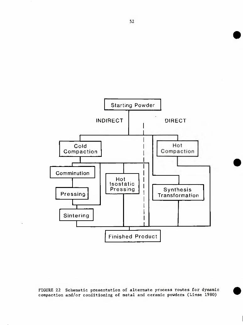
52
Starting Powder
INDIRECT DIRECT
Cold Compaction
J: I
Comminution
Pressing
I I
Hot Isostatic Pressing
Sintering
I
Synthesis Transformation
Finished Product
FIGURE 22 Schematic presentation of alternate process routes for dynamic compaction and/or conditioning of metal and ceramic powders (Linse 1980)
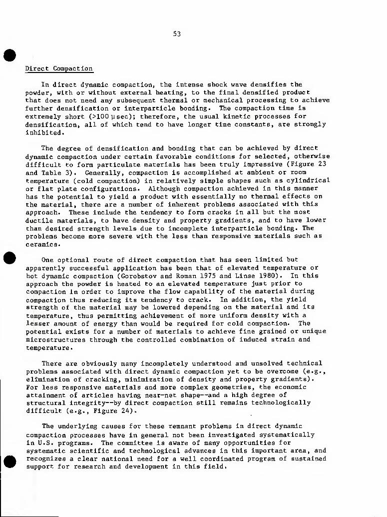
53
Direct Compaction
In direct dynamic compaction, the Intense shock wave densifies the powder, with or without external heating, to the final densified product that does not need any subsequent thermal or mechanical processing to achieve further densifIcation or Interpartlcle bonding. The compaction time Is extremely short (>100ysec); therefore, the usual kinetic processes for densification, all of which tend to have longer time constants, are strongly inhibited.
The degree of densification and bonding that can be achieved by direct dynamic compaction under certain favorable conditions for selected, otherwise difficult to form particulate materials has been truly Impressive (Figure 23 and Table 3). Generally, compaction is accomplished at ambient or room temperature (cold compaction) in relatively simple shapes such as cylindrical or flat plate configurations. Although compaction achieved in this manner has the potential to yield a product with essentially no thermal effects on the material, there are a number of Inherent problems associated with this approach. These include the tendency to form cracks in all but the most ductile materials, to have density and property gradients, and to have lower than desired strength levels due to incomplete interpartlcle bonding. The problems become more severe with the less than responsive materials such as ceramics.
One optional route of direct compaction that has seen limited but apparently successful application has been that of elevated temperature or hot dynamic compaction (Gorobstov and Roman 1975 and Llnse 1980). In this approach the powder is heated to an elevated temperature just prior to compaction in order to Improve the flow capability of the material during compaction thus reducing its tendency to crack. In addition, the yield strength of the material may be lowered depending on the material and its temperature, thus permitting achievement of more uniform density with a lesser amount of energy than would be required for cold compaction. The potential exists for a number of materials to achieve fine grained or unique microstructures through the controlled combination of induced strain and temperature.
There are obviously many incompletely understood and unsolved technical problems associated with direct dynamic compaction yet to be overcome (e.g., elimination of cracking, minimization of density and property gradients). For less responsive materials and more complex geometries, the economic attainment of articles having near-net shape—and a high degree of structural integrity—by direct compaction still remains technologically difficult (e.g., Figure 24).
The underlying causes for these remnant problems in direct dynamic compaction processes have in general not been Investigated systematically in U.S. programs. The committee is aware of many opportunities for systematic scientific and technological advances in this important area, and recognizes a clear national need for a well coordinated program of sustained support for research and development in this field.
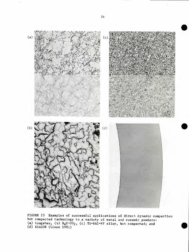
54
(a) (c) t^Wi^^"^'- ^-^^^'^ y-^^" ^^y^-^^*
V'*-
(b)
FIGURE 23 Examples of successful applications of direct dynamic compaction hot compacted technology to a variety of metal and ceramic powders: (a) tungsten, (b) B4C-UO2, (c) Ti-6A1-4V alloy, hot compacted; and (d) SiAlON (Linse 1981)
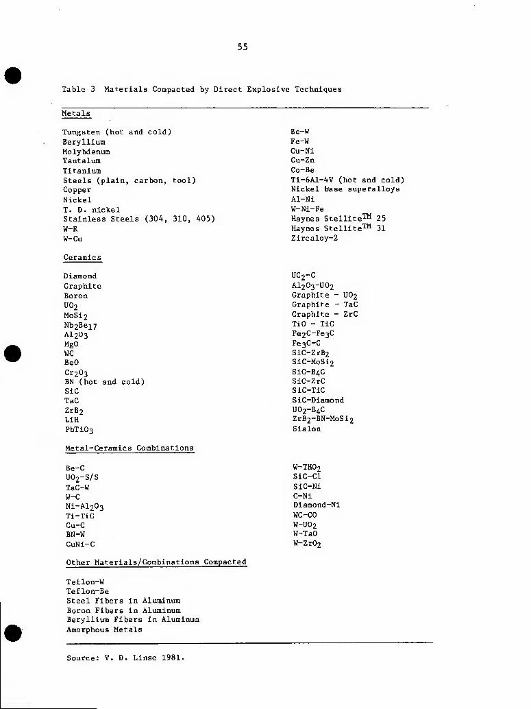
55
Table 3 Materials Compacted by Direct Explosive Techniques
Metals
Tungsten (hot and cold) Beryllium Molybdenum Tantalum Titanium Steels (plain, carbon, tool) Copper Nickel T. D. nickel Stainless Steels (304, 310, 405) W-R W-Cu
Be-W Fe-W Cu-Ni Cu-Zn Co-Be Ti-6A1-4V (hot and cold) Nickel base superalloys Al-Ni W-Ni-Fe Haynes Stellite™ 25 Haynes Stelllte™ 31 Zircaloy-2
Ceramics
Diamond Graphite Boron UO2 M0SI2 Nb2Be;L7 AI2O3 MgO WC BeO Cr203 BN (hot and cold) SiC TaC ZrB2 LiH PbTi03
Metal-Ceramics Combinations
Be-C UO2-S/S TaC-W W-C Ni-Al203 Tl-TiC Cu-C BN-W CuNi-C
Other Materials/Combinations Compacted
Teflon-W Teflon-Be Steel Fibers in Aluminum Boron Fibers in Aluminum Beryllium Fibers in Aluminum Amorphous Metals
UC2-C AI2O3-UO2 Graphite - UO2 Graphite - TaC Graphite - ZrC TiO - TiC Fe2C-Fe3C Fe3C-C SiC-ZrB2 SiC-MoSi2 SiC-Bz,C SiC-ZrC SiC-TiC SiC-Diamond UO2-B4C ZrB2-BN-MoSi2 Sialon
W-THO2 SiC-Cl SiC-Ni C-Ni Diamond-Ni WC-CO W-UO2 W-TaO W-Zr02
Source: V. D. Linse 1981.
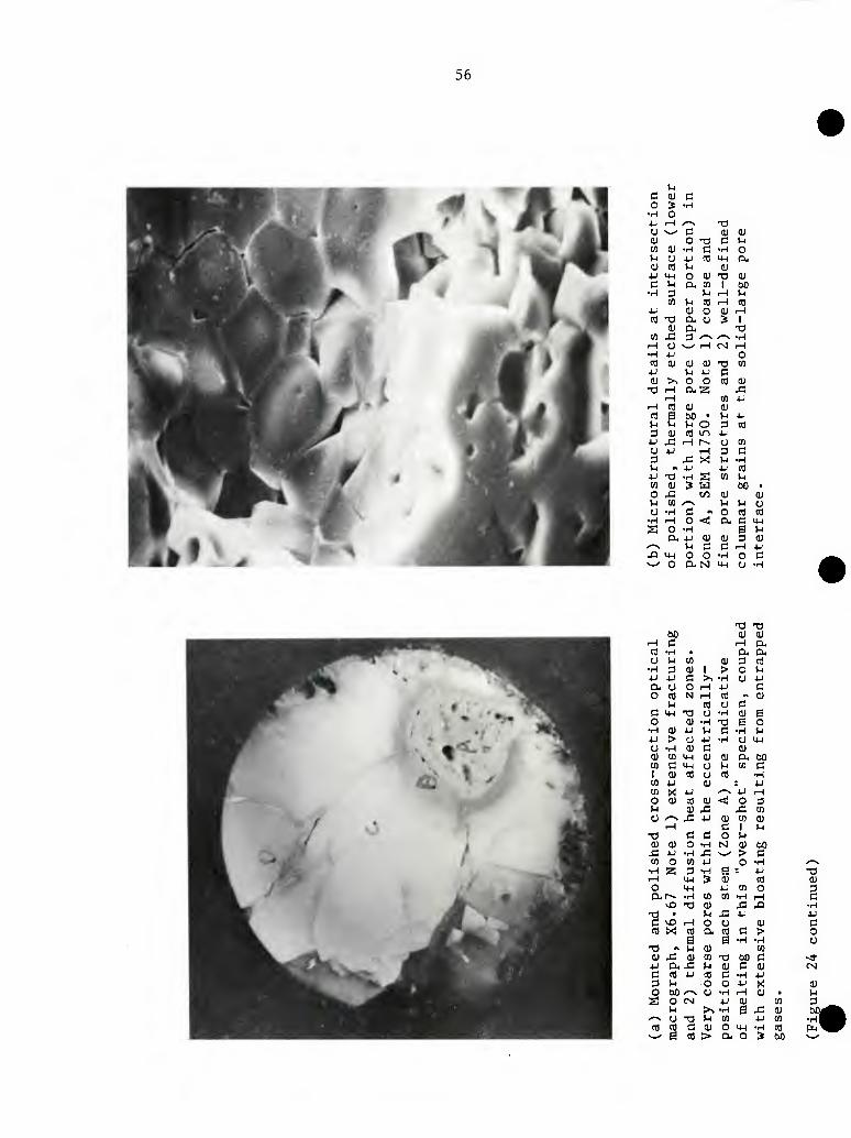
56
u c oj c o S •H
•r^ O 4- J-t *^-N X) o ^-^ (3 eu eu 0) O T3 C u en 0) ■H c ■H o u o 4J CO M-l ex 0) (0 )-l (U 4-' 4-1 o eu XI (U
c s- a- CD 1 60 •H d U ^ l-l
CD P cfl 1—1 CO 4- eu O eu TH
(0 -a a, O S 1 0) ex XI
en j= 3 /^ ^^ •H
.-1 o v_^ 1—1 (N i-H
•H 4-' O Cfl (U 0) 0) X3 en 4-' >-l 4-1 C OJ >, o o CO cu
T3 T-H o-z; X T—1 CD 4-'
--I « QJ eu CO B (50 • u 4J
^ V4 M o 3 CO
3 <U CO LO 4-
4-1 XI TH r^ CJ Cfl
O u iH 3 3 3 j: x: u •H (-1 " ij 4J cfl
4J -O •H s CD M Cfl OJ 3 w 00 • o ^ C/3 (U (U u to ^-s l-l U o O -H C «S O Cfl cfl
•H 1—1 o <C a. 3 4-1
S o •H B (-1
n- JJ <u (U 3 eu /'N M c c r-H 4-1 -Q IM O o •H o c s_/ O (XN 4H CJ •H
XI XI
60 eu eu ^ c iH ex n3 -H • ex a o u CD eu 3 cfl
•H 3 eu 1 > o l-l
4J 4J C >. •H o 4J
tx O 0 iH 4J c O CO N iH CO •\ 0)
l-l CO O 3 C 4-1 T3 O •H eu B o eu •H XI S o
•H 0) 4J U 3 •H u 4J > o 4J •H O 4-1 O -H 0) C CU 0) cn y-l eu (U CX 00 en C C+-I o l-l en 3 1 0) CO o Cfl •H CD 4J (U : 4J CD X 4J .^^ 4J rH
0 eu CO (U <; O 3 1-1 eu x J3 Cfl
O '-v X 4-1 eu Cfl 0) ■H 3 1 l-l
T) C 3 0 u 01 CD o •H tsl Oi 00
J2 4J •H X ^■~^ > c CO O CD 4-1 0 •H ^^
•H Z 3 •H B 4J XI ,—1 M-( S (U cfl eu O 4-1 4J cn 0 3 SX r-~ •H Cfl Cfl •H ^ 3
o X) (U X XI •H
XI • 1-1 JZ 4J 4J
C o ■H o o eu 3 cfl XI CO ex cfl 3 > O
B B •H •H O X) « )-l eu en (U 42 eu CO XI 60 3 <a- 4j CK x; u eu 3 OJ CSJ
e CO 4-1 cfl 3 •H 4J
3 1-1 0 O 4J >< eu O SO ^^ O •H rH eu • M S o cs 4J (U cn 3
VJ >. •H B X cu 60 /-v O X3 Ui Cfl 4^ Cfl •H
CO eg d eu O 4-1 •H CO Pu ^ B CO > cx o » 00 •>.^
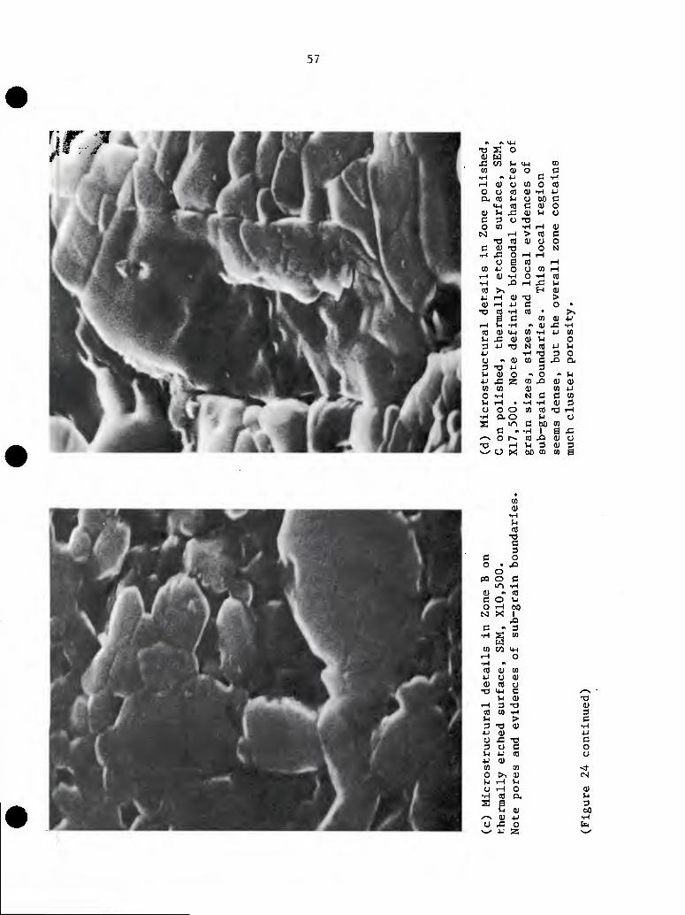
57
nr -p -a S o (U w
J3 en VJ M-I to (n <u o c
•iH - u C •H rH QJ o to o to O O CO 4) 1-1 4-' CX ffl W O 00 C
14-1 CO C a) o 4) ^ x; 0) V4 o C 3 O TS o tn •H iH (U N ^ > to c
T3 CO (U o o C <U T3 o N
■H J= O -H iH o e CO iH
to 4-1 O O CO iH .H 0) •H O •H to •H XI rH x; l-l
CO >, H 0) 4-J rH 0) T3 > 0) ■—1 4J C o • -a tfl •H to • >,
e c to (U t-i r-l VJ ■H CD X •H (fl 0) IM to T-l 4J to tJ J= 01 CU U o 3 iJ -a N CO 4J u 4J •H X) 3 o o » oj to C X a. 3 xl 4J 3 (-1 0) o •> O ^ M 4J X. Z to XI 0) CD CO to (U to 4J O -r^ N d c to U .H . -H •H 0) 3 o o o to CO ■a iH
•H ao VJ o S ir, C bO to
c » -r-l 1 s X /-^ O t^ to XI 0) o XI r-l !-l 3 0) 3 ^ u
undarl
es.
X
g to CO a
c o o • ja
o PQ O c
iri •H 01 « CO C O ^4 O r-\ 60 M X i p « 3
•H S CO W
tn en 4-1 t-( O •H "
Cfl (U CO U O CU 0) CO y
TJ 14-1 (3 /-^ u 0) XI
r-l 3 X) CU CO CO •H 3 u > C 3 -O 0) . •H AJ 01 +J O J= X) c 3 O d o l-l 4.' CO o 4J 0) cn CO <f o >, (U CN U rH M O r-l O CU
•H CO Q, l-l
2 e 3 <U 00
/-^ 0) 4J •r-l O ^ o b
^^ u 3 s-^
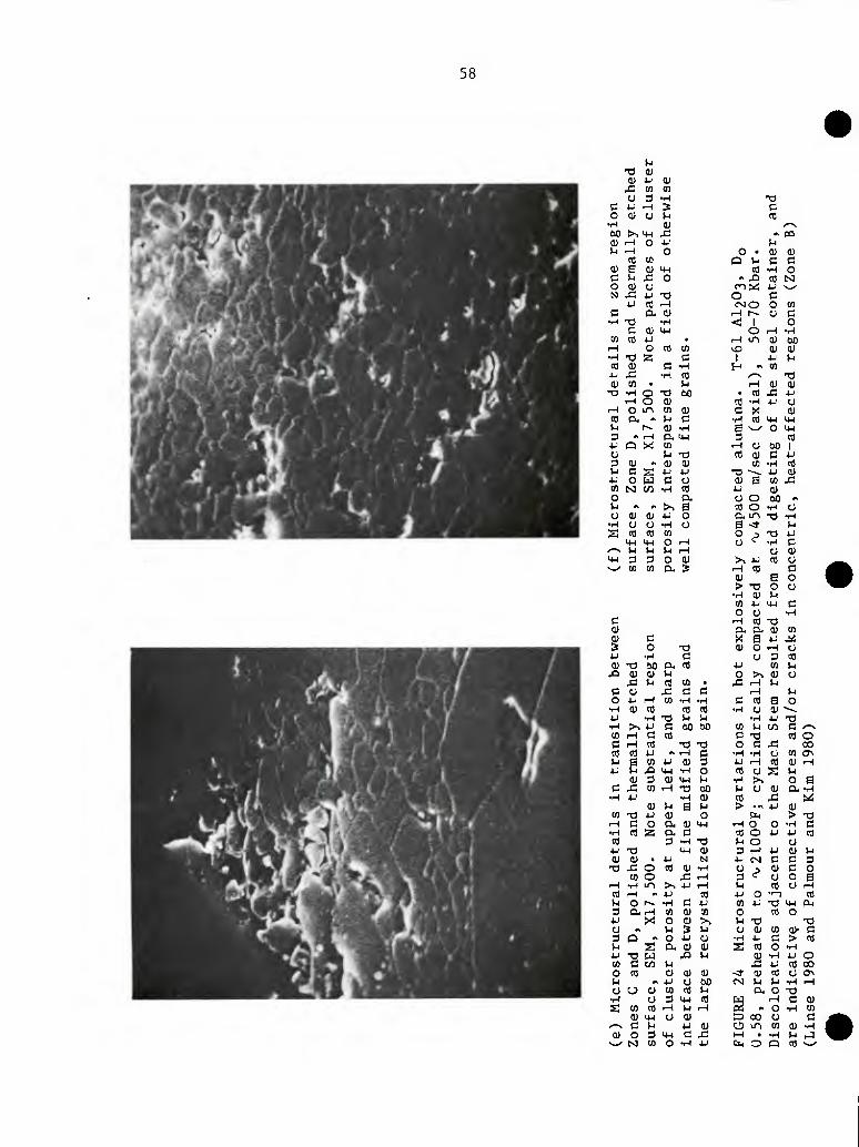
58
T3 0) <u 4-J 0)
x: tn CO o 3 •H T3
c 4- rH 3 C o 0) O M to
•H !U •-N 60 t>>H-( J5 M m (U iH o •M (H U 1—1 o o . 0) 0)
to tn o u d d QJ e d) MH to •H o c u £ o » -Q to N o tu CJ rot^ JJ ^_^ N x: 4J •a O d
4J to rH csiO o to c a- !U rH r-» o d
•H T3 •iH < 1 o C 0) 4H O rH •H
«1 to •u • rH LO <u 60 iH o to tn ^ (U 01 •H T) 3 d 1 JJ U
CO QJ d •H H •> to JJ 4= •iH to ^^ X) 0) tfl • u rH 01 0)
T3 •H O T3 60 • to x: J^ ■H o (U CO -H JJ u
-H O in CO (U d x 0) to a. •s U d ■H to MH MH )-i r~- (U •H E ^ O IJH d •s rH a. iJH 3 to t Q X CO rH U 60 1 u u XI to 0) d u 3 !U «t Q) tu tn •H to l-i C 2^ 4J u T3 ^ JJ 0)
■!-■ o [jj d o tu 0 to x: CO M c« •H to J-' tu O a o o 60 ** l-l ** ^ >^ 0 to o •H u o iV tu 4J o a, m X) •H
•H O o •H o B <t VH
S to to CO ° P T3 JJ 4-1 U-( o rH •H d
^v M VJ u <H O 0) 4-1 3 3 o tu >, JJ CO u ^^ to tn ex 3 <-{ to
tu > 13
•H 0) CD JJ 0 O
e o u
MH
d o o d
•H c T-i CO T3 0) EL O. (U to <u d X 8 iJ ^ s o Xl <u o rH o 4^' ■H d o 3 to (U T3 ao a. to JJ CD u
J3 tu 0) u o >-, i) o J= )-i to to • -C rH U
c o J= d d ^ VJ
o 4J rH tn •H •H d to B o ■rH 0) to to to •H O (U 4J •r^ TJ u h •rH JJ T3 ■H >^ ■U d 60 60 tn u t/3 d ^—N to iH d to d T3 to o c r—l to ■a T) o d x: 00 CO to jj #t rH d •H -H o tn a\ VJ g tn •u <\) 3 JJ r-t to 0) rH JJ ^ XI UH •H o CO O s u
01 3 tu MH (-1 •H >, o Q a ^ CO rH -a 60 u u tu o- •H
•H 4J •H (U to XI i^ (U )H e iH > •" JJ 0)
(0 13 u 0) o fa > X) .H C o (i !U 4H rH O o •H d •H to a Ch d to O JJ JJ to to 3 ■H T3 u o o U -a 4H (U 3 rH JJ 0) u 0} 01 • 4J N J- r-j d d 3
T3 x: o to d) •H ^^
01 d O tn o x: rH o o a
.-H •H LTi >. 4J ^ u to o rH to .—I ^ 4J to JJ o ■r-l CO u o r-~ •H d JJ tn JJ Xf 4H CM 3 CXrH to tu to o to O
■u X! o (U >^ u -a X) o ^ )H 3 u O 0) CD QJ. d 3 Q *^ o JJ o ■H JJ d > to 1-1 S Ch (U OJ S to o •H u T3 w J2 n (U TH JJ o to C Crt u J3 JJ to 00 0 to 01 0) 0) <!• 0) CO o CJ> u M 4J O 60 CSl u ^ •H t-t o u 0) CO to u cu O X)
•H o 3 MH to frT ^ d tu s to to rH >H rH 0^ M o ■H en
0) 4H o tu 3 00 o d •^ c n 4J tu tj in CO OJ ■H 0) o 3 UH d x: M . •H WJ rJ
■—^ N] to o •H JJ fn o Q to
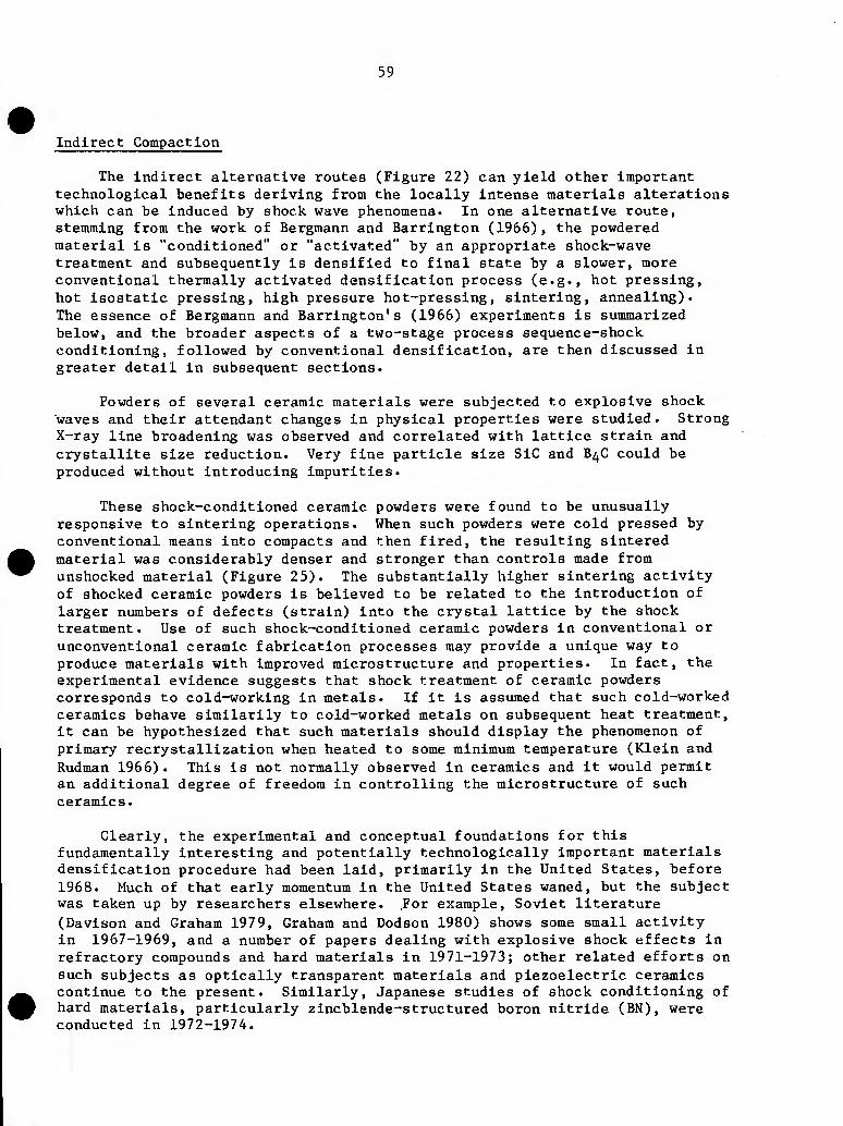
59
Indirect Compaction
The indirect alternative routes (Figure 22) can yield other important technological benefits deriving from the locally intense materials alterations which can be induced by shock wave phenomena. In one alternative route, stemming from the work of Bergmann and Harrington (1966), the powdered material is "conditioned" or "activated" by an appropriate shock-wave treatment and subsequently is densified to final state by a slower, more conventional thermally activated densification process (e.g., hot pressing, hot isostatic pressing, high pressure hot-pressing, sintering, annealing). The essence of Bergmann and Harrington's (1966) experiments is summarized below, and the broader aspects of a two-stage process sequence-shock conditioning, followed by conventional densification, are then discussed in greater detail in subsequent sections.
Powders of several ceramic materials were subjected to explosive shock waves and their attendant changes in physical properties were studied. Strong X-ray line broadening was observed and correlated with lattice strain and crystallite size reduction. Very fine particle size SiC and B4C could be produced without introducing impurities.
These shock-conditioned ceramic powders were found to be unusually responsive to sintering operations. When such powders were cold pressed by conventional means into compacts and then fired, the resulting sintered material was considerably denser and stronger than controls made from unshocked material (Figure 25). The substantially higher sintering activity of shocked ceramic powders is believed to be related to the introduction of larger numbers of defects (strain) into the crystal lattice by the shock treatment. Use of such shock-conditioned ceramic powders in conventional or unconventional ceramic fabrication processes may provide a unique way to produce materials with improved microstructure and properties. In fact, the experimental evidence suggests that shock treatment of ceramic powders corresponds to cold-working in metals. If it is assumed that such cold-worked ceramics behave similarily to cold-worked metals on subsequent heat treatment, it can be hypothesized that such materials should display the phenomenon of primary recrystallization when heated to some minimum temperature (Klein and Rudman 1966). This is not normally observed in ceramics and it would permit an additional degree of freedom in controlling the microstructure of such ceramics.
Clearly, the experimental and conceptual foundations for this fundamentally interesting and potentially technologically important materials densification procedure had been laid, primarily in the United States, before 1968. Much of that early momentum in the United States waned, but the subject was taken up by researchers elsewhere. .For example, Soviet literature (Davison and Graham 197 9, Graham and Dodson 1980) shows some small activity in 1967-1969, and a number of papers dealing with explosive shock effects in refractory compounds and hard materials in 1971-1973; other related efforts on such subjects as optically transparent materials and piezoelectric ceramics continue to the present. Similarly, Japanese studies of shock conditioning of hard materials, particularly zincblende-structured boron nitride (BN), were conducted in 1972-1974.
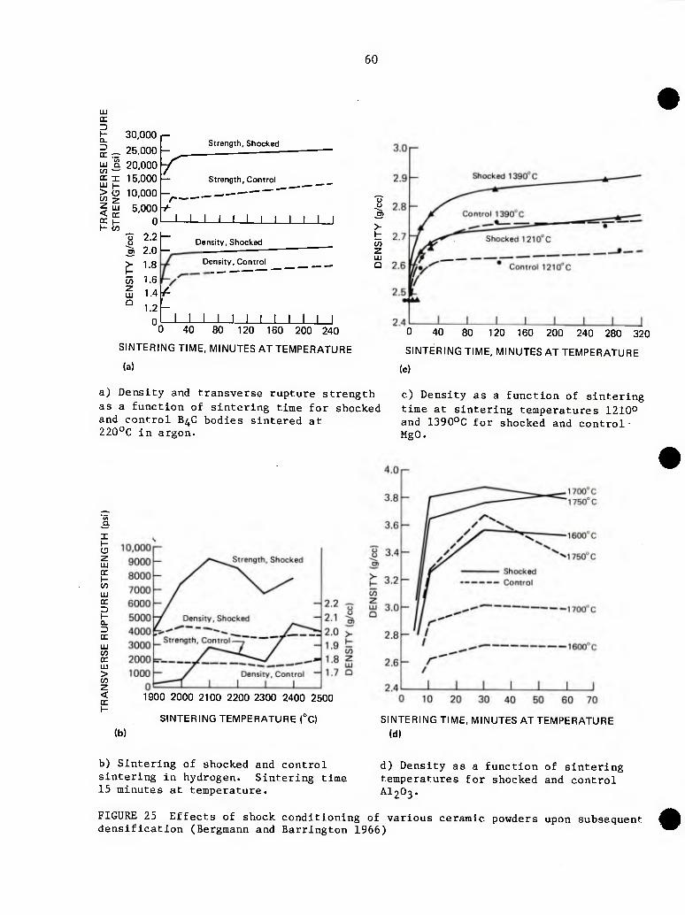
60
cc
I-
D oc LU t/3 CC 1X1 > to z < oc
30,000 p
_ 25,000 -
S 20,000 y I 15,000 -
a 10,000 -.
LU 5,000 oc H 0 CO
-o 2.2 u CT 2.0
> 1.8
w 1.6
Strength, Shocked
/-
J__L
Strength, Control
I I I I I I I
LU Q
V
1.2
0
Density, Shocked
Density, Control
I I I I I I J
C/3 z LU Q
0 40 80 120 160 200 240
SINTERING TIME, MINUTES AT TEMPERATURE
(a)
a) Density and transverse rupture strength as a function of sintering time for shocked and control B^C bodies sintered at 220°C in argon.
0 40 80 120 160 200 240 280 320
SINTERING TIME, MINUTESATTEMPERATURE
(c)
c) Density as a function of sintering time at sintering temperatures 1210° and 1390°C for shocked and control MgO.
a. X
C3 Z
C/3 HI OC
H CL
OC
LU to oc LU > w z < oc 1900 2000 2100 2200 2300 2400 2500
SINTERING TEMPERATURE (°C)
(b) SINTERING TIME, MINUTES AT TEMPERATURE
(d)
b) Sintering of shocked and control sintering in hydrogen. Sintering time 15 minutes at temperature.
d) Density as a function of sintering temperatures for shocked and control AI2O3.
FIGURE 25 Effects of shock conditioning of various ceramic powders upon subsequent denslfIcation (Bergmann and Barrlngton 1966)
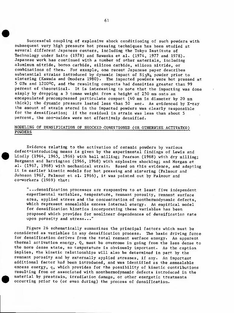
61
Successful coupling of explosive shock conditioning of such powders with subsequent very high pressure hot pressing techniques has been studied at several different Japanese centers, including the Tokyo Institute of Technology under Saito (1978) and Sawaoka et al. (1974, 1977 and 1978). Japanese work has continued with a number of other materials, including aluminum nitride, boron carbide, silicon carbide, silicon nitride, or combinations of them. For example, one recent Japanese paper describes substantial strains introduced by dynamic impact of Si3N4 powder prior to sintering (Kawada and Onodera 1980) . The impacted powders were hot pressed at 5 GPa and 1200OC, and the resulting compacts had densities greater than 99 percent of theoretical. It is interesting to note that the impacting was done simply by dropping a 3 tonne weight from a height of 250 mm onto an encapsulated precompressed particulate compact (40 mm in diameter by 20 mm thick); the dynamic pressure lasted less than 50 sec. As evidenced by X-ray the amount of strain stored in the impacted powders was clearly responsible for the densification; if the residual in strain was less than about 5 percent, the non-oxides were not effectively densified.
MODELING OF DENSIFICATION OF SHOCKED CONDITIONED (OR OTHERWISE ACTIVATED) POWDERS ~~~~~"
Evidence relating to the activation of ceramic powders by various defect-introducing means is given by the experimental findings of Lewis and Lindly (1964, 1965, 1966) with ball milling; Pearson (1968) with dry milling; Bergmann and Harrington (1966, 1968) with explosive shocking; and Morgan et al. (1967, 1968) with mechanical strain. Based on this evidence, and adapting it in earlier kinetic models for hot pressing and sintering (Palmour and Johnson 1967, Palmour et al. 1966), it was pointed out by Palmour and co-workers (1969) that:
"...densification processes are responsive to at least five independent experimental variables, temperature, remnant porosity, remnant surface area, applied stress and the concentration of nonthermodynamic defects, which represent annealable excess internal energy. An empirical model for densification kinetics incorporating these variables has been proposed which provides for nonlinear dependences of densification rate upon porosity and stress..."
Figure 26 schematically summarizes the principal factors which must be considered as variables in any densification process. The basic driving force for densification derives from the total remnant surface energy. An apparent thermal activation energy, Q, must be overcome in going from the less dense to the more dense state, so temperature is obviously important. As the caption implies, the kinetic relationships will also be determined in part by the remnant porosity and by externally applied stresses, if any. An important additional factor had been introduced, and was identified as the annealable excess energy, q, which provides for the possibility of kinetic contributions resulting from or associated with nonthermodynamic defects introduced in the material by prestrain, irradiation damage, or other energetic treatments occurring prior to (or even during) the process of densification.
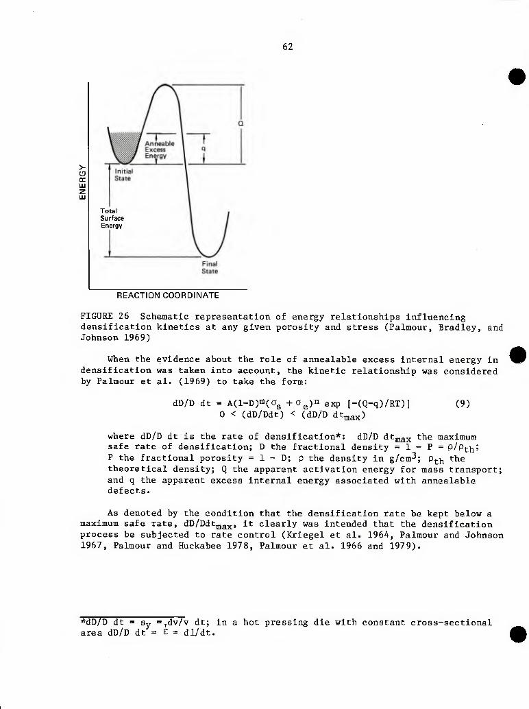
62
Total Surface Energy
REACTION COORDINATE
FIGURE 26 Schematic representation of energy relationships influencing densification kinetics at any given porosity and stress (Palmour, Bradley, and Johnson 1969)
When the evidence about the role of annealable excess internal energy in densification was taken into account, the kinetic relationship was considered by Palmour et al. (1969) to take the form:
dD/D dt = A(l-D)m(ag +0^)11 exp [-(Q-q)/RT)] 0 < (dD/Ddt) < (dD/D dt^3x)
(9)
where dD/D dt is the rate of densification*: dD/D dt^^^ the maximum safe rate of densif ication; D the fractional density = 1 - P = p/p^-j^; P the fractional porosity = 1 - D; p the density in g/cm^; p^|^ the theoretical density; Q the apparent activation energy for mass transport; and q the apparent excess Internal energy associated with annealable defects.
As denoted by the condition that the densification rate be kept below a maximum safe rate, dD/Ddt^^^^^, it clearly was intended that the densif ication process be subjected to rate control (Kriegel et al. 1964, Palmour and Johnson 1967, Palmour and Huckabee 1978, Palmour et al. 1966 and 197 9).
*dD/D dt = Sy =,dv/v dt; in a hot pressing die with constant cross-sectional area dD/D dt = e = dl/dt.
63
Future Prospects—Shock Conditioning and Subsequent DenslfIcation
In considering the present status and future potential of two-stage processing of shock-conditioned powders, it is convenient to treat the two stages separately, at least from the experimentalist's viewpoint. The two steps will, for example, be rather likely to be carried out in separate, often distant facilities and by persons drawn from quite different professional backgrounds such as shock wave physics and/or mechanical engineering and ceramic and/or powder metallurgy processing, sintering, etc.
PRECONDITIONING OF POWDERS BY SHOCK-WAVES
The basic parameters for accomplishing this phase of the two-stage process were well established by Bergmann and Barrington (1966) and their applicability to a number of oxide and non-oxide systems of technological interest were demonstrated (Barrington and Bergmann 1968). The primary goals of the shock-induced preconditioning step are considered to be uniform Introduction of substantial mlcrostrain (up to %5 percent), with or without comminution, in partlculate masses of economic size. Ideally, the shocked powder mass should be either free of cracks and flaws and very uniformly compacted to some intermediate level of density from which state it can be further denslfled directly by sintering or hot pressing, or sufficiently friable to permit comminution and recompaction to assure the attainment of some uniform, substantially flaw-free, high level of green density by conventional process means prior to final denslfication. For most materials, the latter course seems more likely to be successful as a reliable process method.
The uniformity criterion at the powder conditioning stage is an important one for the success of denslfication in the second stage and, for most materials, is considered almost to preclude the effective use of cylindrical geometries for explosive shock preconditioning treatments. Several authors have noted the marked radial gradients (in terms of energy density, temperature, Internal strains, grain size, etc.) that result from explosive compaction in such cylindrical configurations; Greenham and Richard's (1970) carefully documented study is one excellent example (see also Figure 24). Therefore, emphasis in future research and development in this area probably should be placed on the attainment of economic, controlled means for uniform, substantially plane-wave shock treatments of powder masses. Methodologies for both explosive and gas gun generation for plane-wave shock geometries are well known.
I These powder preconditioning goals differ in several significant respects from those that would apply in the case of direct compaction of powders to final density and/or near net shape. For example, it is clearly desirable to strain all individual particles uniformly but it is perhaps not necessary, or even undesirable, to bond them together. Much of the available literature really treats only direct compaction rather than preconditioning per se. Rather different criteria for particle sizing, precompactlon, encapsulation and shock-wave parameters (velocities, pressures, dwell times, etc), are likely to be required if preconditioning of such powders is to be fully optimized and brought under close control.
J
64
Densificatlon of Shock-Conditioned Powders
The basic goals (densificatlon, bonding) of this final step of the two-phase process are not significantly different from those of conventional densifIcatlon processes such as sintering, hot pressing, and hot Isostatlc pressing. To these may be added other auxilliary requirements such as grain growth control and/or preservation of metastable phases. The basic thermally activated transport mechanisms (principally surface, grain boundary and volume diffusion) already are well known, and their respective roles in the various stages of the overall densificatlon process are the continuing subject of vigorous scientific Inquiry and debate (Exner et al. 1973; Exner and Petzow 1973; Johnson 1978, 1980; Coble and Cannon 1978). Though there is abundant evidence that shock-induced prestrain and the high concentrations of resulting crystalline defects have a pronounced beneficial effect on the slnterability of shock-conditioned powders and some attempts have been made to account—at least empirically—for the obvious effect of prestrain on the densifIcatlon kinetics in such systems, there is, at least for ceramics, no sound fundamental treatment at the mechanistic level to account theoretically for the resulting enhancement of densifIcatlon.
Unfortunately, most of the effective demonstrations of enhanced slnterability of shock-conditioned partlculates have been experimentally confounded in one or more senses. Thus, clear attribution of the overall enhancement in slnterability to certain specific phases of the complex densificatlon process will be needed in the first step to Identify the various effects of dynamic shock conditioning in step one on (1) particle comminution and (2) Internal strain per se, and in the second step on (1) green compaction (and its uniformity), (2) particle coordination distributions in the green compact, and (3) thermal responses, including the onset of densificatlon, the onset of pore entrapment, grain growth, etc. To date, most thermal processing of such shocked materials has tended to be of the "brute force" kind involving fast rates, high temperatures, high pressures, etc. Such "power" methods work after a fashion but often mask Important intermediate stage events and seldom yield optimal densities and/or microstructures.
It can be argued that the more intense the shock-conditioned prestrain, the higher the total excess energy per unit volume in the green compact at any given level of green density and, hence, the greater the risk of dissipating that energy needlessly in other thermally activated processes, which might not result in actual densificatlon. Of all known firing procedures, only the rate-controlled process methodology developed at North Carolina State University (Kriegel et al. 1964, Barnes 1967, Palmour 1972, Palmour and Johnson 1967, Palmour and Huckabee 1975 and 1978, Palmour et al. 1966, 1969, 1977 and 1979, Hare and Palmour 1978) provides Inherently for feedback-controlled release of that energy in ways and at rates that can best transform it into maximum utilization toward actual densificatlon. Although rate-controlled densificatlon, known to be very effective in achieving near-optimal densifIcatlon of conventionally processed ceramic materials and in yielding controlled uniform fine microstructure (Figures 27 and 28), was first proposed for hot pressing or sintering of shock-conditioned
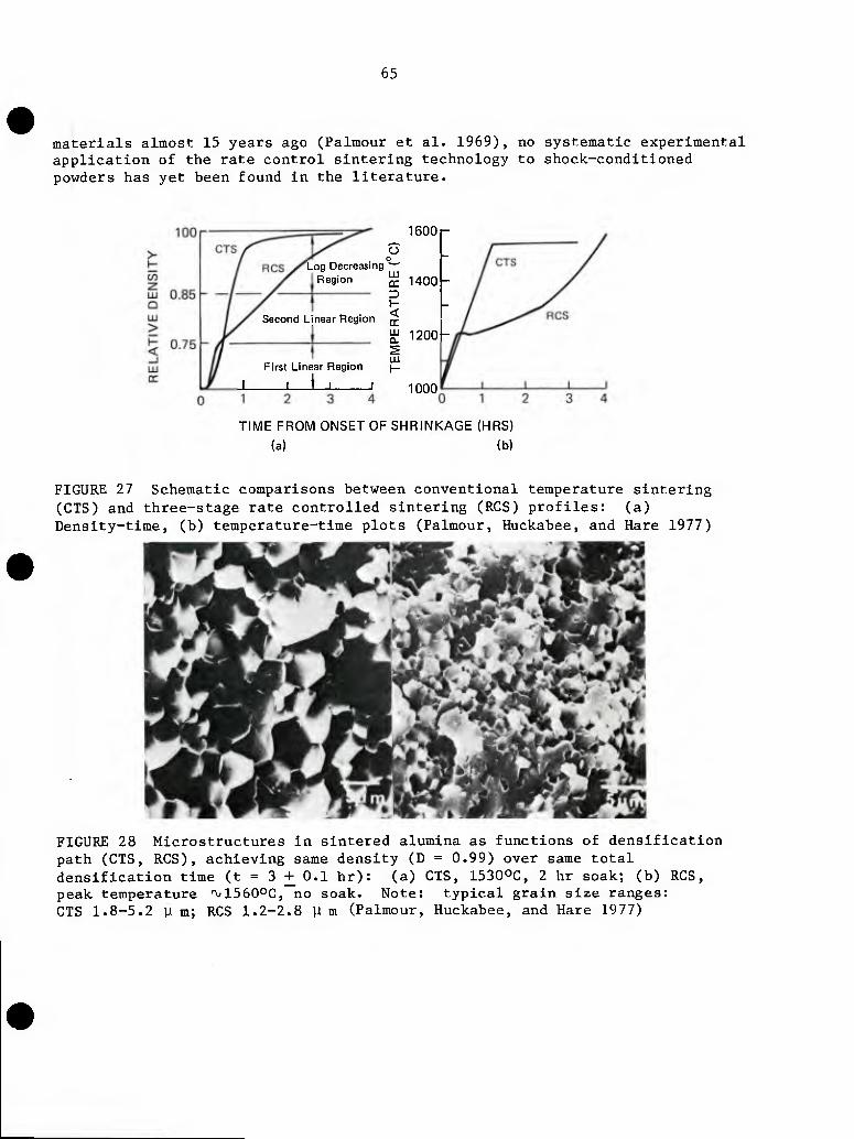
65
materials almost 15 years ago (Palmour et al. 1969), no systematic experimental application of the rate control sintering technology to shock-conditioned powders has yet been found in the literature.
1600r o
, o Log Decreasing
Region ^ 1400-
I- Second Linear Region ^
^ 1200-
First Linear Region )_
J I i_l I 1000
TIME FROM ONSET OF SHRINKAGE (HRS) (a) (b)
FIGURE 27 Schematic comparisons between conventional temperature sintering (CTS) and three-stage rate controlled sintering (RCS) profiles: (a) Density-time, (b) temperature-time plots (Palmour, Huckabee, and Hare 1977)
FIGURE 28 Microstructures in sintered alumina as functions of densification path (CTS, RCS), achieving same density (D = 0.99) over same total densification time (t = 3 + 0.1 hr): (a) CTS, 1530OC, 2 hr soak; (b) RCS, peak temperature ^^ISSOOC, no soak. Note: typical grain size ranges: CTS 1.8-5.2 y m; RCS 1.2-2.8 y m (Palmour, Huckabee, and Hare 1977)
66
REFERENCES
Barnes, L. D. 1967. Rate controlled hot pressing of magnesium aluminate spinel. M. S. thesis, North Carolina State University.
Barrington, J. and 0. R. Bergmann. 1968. Preparation of Brittle Inorganic Polycrystalline Powders by Shock-Wave Techniques, U. S. Patent 3,367,766.
Bergmann, 0. R. 1966. Aluminum-bonded titanium carbide cermets. Bulletin of the American Ceramic Society 45:639.
Bergmann, 0. R. and J. Barrington. 1966. Effect of explosive shock waves on ceramic powders. Journal of the American Ceramic Society 49:502.
Bogdanov, A. R., A. S. Lazarev, 0. V. Roman, and V. Ya Fiers. 1973. Compression of metal powders by flat high explosive charges. Poroskhklovaya Metallurgiya 127:131.
Carlson, R. J., S. W. Procumbka, and C. C. Simons. 1966. Explosive compaction of ceramic materials. Bulletin of the American Ceramic Society 45:266-270.
Clyens, S. and W. Johnson. 1977. The dynamic compaction of powdered materials. Materials Science and Engineering 30:121-139.
Davison, L. and R. A. Graham. 1979. Shock compression of solids. A Review Section of Physics Letters, Physics Reports 55:257-379.
Exner, H. E. , G. Petzow, and P. Wellner. 1973. Problems in the extension of sintering theories to real systems, In_ Sintering and Related Phenomena. Materials Science Research: 6. Plenum Press. G. C. Kuczynski, Editor.
Exner, H. E. and G. Petzow. 1980. A critical evaluation of shrinkage equations in sintering processes, Materials Science Research: 13. Plenum Press. G. C. Kuczynski, Editor.
Grady, D. E. 1980. Review of the phase transformation of brittle solids. Journal of Geophysical Research 85:913-24.
Graham, R. A. and B. W. Dodson. 1980. Sandia National Laboratories, Bibliography on Shock Induced Chemistry, Technological SAND 801642, Contract DE-AC04-DP00789, August, 1980.
Greenham, A. C. and B. P. Richards. 1970 Explosive shocking of alumina powder. Trans. Brit. Ceram. Soc. 69:115.
Gorobstsov, V. G. and 0. V. Roman. 1975. Hot explosive pressing of powders, The International Journal of Powder Metallurgy and Powder Technology 11:1.
67
Hare, T. M. and H. Palmour. 1978. Effect of process optimization on properties of alumina sintered under rate control, In Ceramic Processing Before Firing. John Wiley and Sons. G. Onoda, Jr. and L. L. Hanch, Editors.
Heckel, R. W. and J. L. Youngblood. 1968. X-ray broadening study of explosively shocked MgO and a AI2O3 powders. Journal of the American Ceramic Society 51:398-401.
Hoenig, C. L., A. Holt, M. Finger, and W. Kuhl. 1975. Hydrodynamic modeling and explosive compaction of ceramics. Presented at the 6th International Conference on High Energy Rate Fabrication, Denver, Colorado.
Hoenig, C. L. and C. S. Yust. 1981. Explosive compaction and microstructural analysis of AIN, Amorphous Si3N4, Boron and AI2O3 Ceramics, The American Ceramic Society Bulletin 60:1175-117 8.
Kawada, K. and A. Onodera. 1980. Effect of residual strain on high pressure densification of non-oxide ceramics. Journal of American Ceramic Society 59:1151-1152.
Klein, M. J. and P. S. Rudman. 1966. X-ray broadening in explosively shocked magnesium oxide. Phil. Mag. 15:1199-1206.
Kim, C. H. and H. Palmour. 1970. Microstructural alterations in alumina ceramics associated with ballistic impact events. Technical Report 70-8, Contract No. N00014-68-A-0187.
Kriegel, W. W., H. Palmour, and D. M. Choi. 1964. Preparatiion and mechanical properties of spinel. In Proceedings of British Ceramic Research Association Symposium, London. Academic Press. P. Popper, Editor.
Kuz'min, G. E. and A. M. Staver. 1973. Determination of the flow parameters with shock loading of powdered samples. Gorenlya i vzrya 9:898.
Lewis, D. and M. W. Lindley. 1964. An X-ray line broadening study of the introduction and removal of strain in some refractory oxides. Journal of American Ceramic Society 48:652.
Lewis, D. and M. W. Lindley. 1965. Strain-induced activity in thoria and its relief with temperature. Journal of Nuclear Materials 17:347.
Lewis, D. and M. W. Lindley. 1966. Enhanced activity and characterization of ball-milled alumina. Journal of American Ceramic Society 49:49.
Lin, I. J. and S. Nadiv. 1979. Review of the phase transformation and synthesis of inorganic solids obtained by mechanical treatment (mechano-chemical reactions), Materials Science and Engineering 39:193-209.
Linse, V. D. 1980. Dynamic compaction of ceramics and metals. Presented at the H. J. Kraner Award Symposium: Innovative Forming Methods in Ceramic and Metals Systems, Lehigh Valley Section of the American Ceramic Society, Bethlehem, Pennsylvania.
68
Linse, V. D. 1981. Explosive Compaction at Battelle Columbus Laboratories. Presented at the Materials Research Council meeting, La Jolla, California, July 10, 1981.
McKenna, P. M. 1955. Process for the explosive pressing of powdered composites, U. S. Patent 2,648,125.
Morgan, C. S. 1967. Densification kinetics during nonisothermal sintering of oxides, In_ Proceedings of International Symposium on Special Topics Ceramics, 19:349-361. Alfred University, New York.
Palmour, H., D. R. Johnson, and D. R. Rummler. 1966. General Phenomenological model for stress-augumented sintering. Presented to the Basic Science Division at the 68th Annual Meeting of the American Ceramic Society, Washington, D.C.
Palmour, H. and D. R. Johnson. 1967. Phenomenological model for rate-controlled sintering. In Sintering and Related Phenomena, pp. 779-791. New York: Gordon and Breach, G. C. Kuzynskl, Editor.
Palmour, H., D. R. Johnson, C. H. Kim and C. E. Zimmer. 1969. Fractographic and Thermal Analyses of Shocked Alumina, Technical Report 69-5, Contract No. N00014-68-A-0187.
Palmour, H., R. A. Bradley, and D. R. Johnson. 1969. A reconsideration of stress and other factors in the kinetics of densification, In Kinetics of Reaction in Ionic Solids, Materials Sciences Research: 4. Plenum Press. T. J. Gray and V. D. Frechette, Editors.
Palmour, H. 1972. The role of densification dynamics in hot pressing of spinel and other oxides, Ln U.S. Japan Seminar Reports on Basic Science of Ceramics, Equilibria, and Kinetics in Modern Ceramic Processing, Japanese Organizing Committee.
Palmour, H. and J. L. Huckabee. 1975. Process for Sintering Finely Derived Particulates and Resulting Ceramic Products, U.S. Patent 3,900,542.
Palmour, H., M. L. Huckabee, and T. M. Hare. 1977. Microstructural development during optimized rate controlled sintering. In Ceramic Microstructures 1976. Westview Press. R. M. Fulrath and J. A. Pask, Editor.
Palmour, H. and M. L. Huckabee. 1978. Rate controlled sintering. In Proceedings of the International Symposium on Factors in Densification and Sintering of Oxide and Non-oxide Ceramics, S. Somiya, Editor.
Palmour, H., M. L. Huckabee, and T. M. Hare. 1979. Rate controlled sintering; principles and practice, In^ Sintering New Developments, Materials Science Monographs 4, Elsevier Publishing Corporation.
Pearson, A., J. E. Marhanka, G. McZura, and L. D. Hart. 1968. Dense, abrasion resistant, 99.8% alumina ceramic, Bulletin of the American Ceramic Society 47:654-658.
69
Priimmer, R. A. 1973. Explosive compaction of ceramic and metal powders and composites, Ber. Deut. Keram. Ges. 50:75.
Raybould, D. 1980. The production of strong parts and non-equilibrium alloys by dynamic compaction. Presented at the International Conference on the Metallurgical Effects of High Strain-Rate Deformation and Fabrication, Albuquerque, New Mexico.
Roman, 0. V. and A. P. Bogdanov. 1980. Development of explosive compacting methods in powder metallurgy, In Explosive Welding and Forming: 44 (P. M. Institute, USSR). I. Berman and J. W. Schroeder, Editors.
Roman, 0. V. and V. G. Gorobtsov. 1981. Fundamentals of explosive compaction of powders. In Shock Waves and High-Strain-Rate Phenomena in Metals: 829-842. Plenum Press. M. A. Meyers and L. E. Muir, Editors.
Rossi, R. C. and R. M. Fulrath. 1965. Final state densification in vacuum hot pressing of alumina. Journal of American Ceramic Society 48:550-564.
Rummler, D. R. and H. Palmour. 1968. Vacuum hot pressing of magnesium aluminate spinel. Journal of American Ceramic Society 51:320-326.
Rummler, D. R. 1966. Hot pressing kinetics of magnesium aluminate in vacuum. Master of Science Thesis, North Carolina State University.
Saito, S. 1978. Shock synthesis and very high pressure sintering of high dense form of boron nitride, In_ Proceedings of the International Symposium on Factors in Densification and Sintering of Oxide and Non-oxide Ceramics, Tokyo Institute of Technology, Tokyo, Japan. S. Somiya and S. Saito, Editors.
Samsonov, G. V. 1973. Effect of an explosion on carbides heat melt at high temperatures, Fiz. i Khim. Abardotki Materials 5:108.
Sawaoka, A., T. Soma, and S. Saito. 1974. Structure determination of boron nitride transformed by shock compression, Japan Journal of Applied Physics 13:891-892.
Sawaoka, A., S. Saito, and M. Araki. 1977. New type of boron nitride sintered under very high pressure, Proc. International Conference on High Pressure (AIRAPT VI).
Sawaoka, A., K. Kondo, N. Hashimoto, and S. Saito. 1978. Very high pressure sintering of covalent materials. In Symposium on Factors in Densification and Sintering of Oxide and Non-oxide Ceramics. Tokyo Institute of Technology, Tokyo, Japan. S. Somiya and S. Saito, Editors.
Yust, C. S. and L. A. Harris. 1981. Observation of Dislocations and Twins in Explosively Compacted Alumina, In^ Shock Waves and High-Strain-Rate Phenomena in Metals, 50:881-893. Proceedings of an International Conference, Metallurgical Effects High-Strain-Rate Deformation and Frabrication, June 22-26, 1981, Albuquerque, New Mexico. Plenum Press, M. A. Meyers and L. E. Murr, Editors.
Chapter 6
CHARACTERIZATION OF DYNAMICALLY COMPACTED METAL AND CERAMIC POWDERS
Dynamic compaction mitigates the usual mlcrostructural changes associated with conventional powder processing but it can and frequently does bring about large mlcrostructural changes. Foremost is the gross fracturing on both the macroscale and microscale. The gun work of Morris (1979) and Raybould (1975 and 1980) and the explosive studies of Priimmer and coworkers (Balzerowlak et al. 1971) have demonstrated that the gross fracture can be mitigated. The detailed microscopic features characteristic of materials compacted by dynamic means have not been characterized fully but transmission electron microscope (TEM) studies of dynamically compacted metals and alloys have been published. At Lawrence Livermore National Laboratory cylindrically compacted structures of aluminum nitride (AIN) and alumina (AI2O3) formed at 30 to 40 Kb have been examined using TEM techniques. (Hoenig and Yust 1981). The compacted samples were ion milled to the proper thickness. The edges of the samples were strained to the point that individual dislocations could not be distinguished. In the case of AIN, microcracking was minimized although the sample was fractured on a macroscale along the center axis.
Figures 29 illustrates the TEM structures of hot pressed AIN and Figure 30 points out the high dislocation densities near the edge of an explosively compacted AIN sample. Figure 31 shows the core region of the same explosively compacted AIN and one notes the recrystallized structure with fewer dislocations. The main point is that cylindrically compacted samples frequently have a structure that changes continously with position as one proceeds from the outside to the center.
It is evident that at least four types of characterization are needed to understand the details of dynamic compaction of metal and ceramic powders:
1. Characterization of the starting powder (including chemical, particle and crystallite dimension. X-ray lattice measurements, surface area, density of particles, shape distribution and distributions, etc.).
2. Characterization of the Initial pressed powder contained in the die fixture (including green density, porosity, and texture details).
3. Characterization of the experiment in terms of the pressure-time-
temperature relationship (in real time) of the projectile or explosive on the pressed powders.
4. Characterization of the resulting compact both axially and radially (including density versus position and the grain size data and shape observations based on detailed metallographlc as well as X-ray TEM studies) .
71
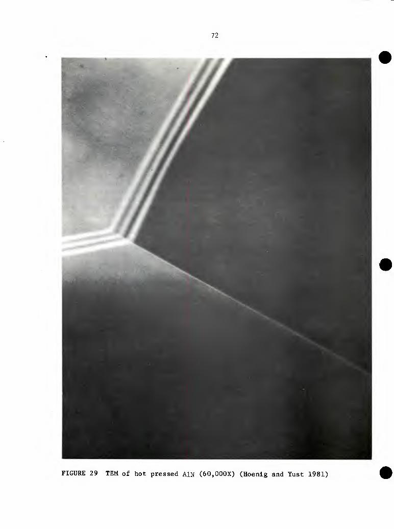
72
FIGURE 29 TEM of hot pressed AlN (60,000X) (Hoenig and Yust 1981)
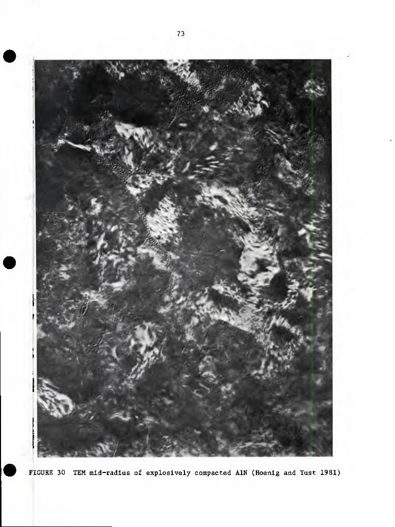
73
FIGURE 30 TEM mid-radius of explosively compacted AIN (Hoenig and Yust 1981)
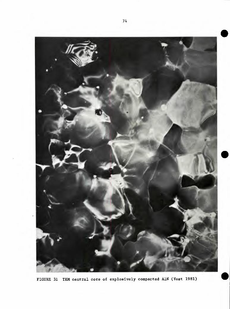
74
FIGURE 31 TEM central core of explosively compacted AIN (Yust 1981)
75
An example of work that characterized the experiment but did not handle the powder Is given In the work of Boade (1968 and 1970). Various Soviet researchers (Derlbas 1977 and Gubareva 1977) did not relate the experiment measurements to the details of the final compaction mlcrostructure.
Dynamic compaction may avoid some undesirable effects of conventional powder processing; however, it clearly produces unique modifications in the material. A study is needed to characterize, in detail, the state of selected materials before and after shock compaction. Detailed studies on the effect of these structures on further thermomechanical processing them should be carried out.
REFERENCES
Balzerowiak, H. P., Fr. Bock-Nussman, and R. PrUmmer. 1971. Uber moglichkeiten zur explosiven verdichtung von pulvern, insbesondere wolfram, nach dem direkt-verfahren [Possible direct methods for explosive compaction of powders, particularly tungsten] High Temperatures-High Pressures 3:517.
Boade, R. R. 1968. Compression of porous copper by shock wave, Journal of Applied Physics 39:5693.
Boade, R. R. 19 70. Principal Hugoniot, second-shock Hugoniot, and release behavior of pressed copper powder. Journal of Applied Physics 41:4542.
Derlbas, A. A. 1977. Explosive compression of steel and copper mixtures, 23 vt. Sib. Otdeleniya Akad Nauk SSSR 3:45.
Gubareva, N. N. 1977. Dependence of copper structure on deformation in explosive loading, Fiz. Gor. 1 Vzr. 13:636.
Hoenig, C. L., and C. S. Yust. 1981. Explosive Compaction and Microstructural Analysis of AIN, Amorphous Si3N4, Boron and AI2O3, Ceramics, Report UCRL-83409, Lawrence Livermore National Laboratory.
Morris, D. G. 1979. A new powder metallurgy method. Journal of Materials Science 14:2523.
Raybould, D. 19 75. The dynamic compaction of aluminum and iron powder. In Proceedings of the 15th International Machine Tool Design and Research Conference. MacMlllan Press Ltd. S. A. Tobias and F. Koenigsberger, Editors.
Raybould D. 1980. Wear-resistant Al-steel mixtures produced by PM technique which avoids sintering. Powder Metallurgy: 37.
Chapter 7
DYNAMIC COMPACTION MODELING AND CODES
Modeling will be an extremely important tool to the understanding and utilization of the dynamic compaction process.
There are a variety of codes available to calculate various one-, two- and three-dimensional problems. The most popular code is called HEMP and it was developed by Wilkins (1969); versions of it are published by other laboratories using different acronyms. The HEMP program solves the equations of continuum mechanics formulated in Lagrange coordinates. The finite-difference operators are centered in space and time to give second-order accuracy. Incremental plasticity theory is followed to describe large plastic deformation with rotation. The von Mises hypothesis is applied in a manner to satisfy implicitly the flow law that requires the plastic-strain-rate vectors to be normal to the yield surface.
Other versions of Lagrange codes include EPIC-3 developed by Johnson at Minneapolis Honeywell. EPIC-3 is a finite element code. Work by Holmquist at Lawrence Livermore National Laboratory on Lagrange finite element programs has proven very successful and 2-D and 3-D versions exist with names of Dyna 2-D and Dyner 3-D. It is claimed that these programs are more efficient and effective than the finite difference codes. The Lagrange codes are considered more accurate and cheaper if the problem does not involve too large a displacement. If massive deformations are involved, a code with Eulerian coordinates is needed, and the code developed by Matsuka and Durret called HULL is in frequent use.
The important point is that there are a large number of codes that require various input parameters such as material strength, thermal softening, and fracture in various modes. The main problem is that there is no satisfactory material description for the dynamic compaction process. For example, one cannot take slow strain rate data such as might be obtained from a triaxial test and reproduce what happens in a dynamic compaction. The material responds in a different way depending on its powder properties (i.e., size, shape, impurities, etc.) and the mechanism by which it densifies (Herman 1969, Hoenig et al. 1977, Holt et al. 1973). AI2O3 in its dynamic compaction tends to approach the hydrostat very quickly, which probably is caused by fracture or a liquid-surface-like bonding due to frictional effects. Metal samples, on the other hand, exhibit significant plastic response and do not need the "melting phenomena" to consolidate. The effect of the breakup of surface films also is not tractable by current codes; in
i 77
78
particular, the effect of this breakup on resultant properties and density is not satisfactorily handled. The technology of dynamic compaction clearly needs appropriate materials models in order to calculate and extrapolate as the computer codes currently exist.
REFERENCES
Hermann, W. 1969. Constitutive equations for the dynamic compaction of ductile porous materials. Journal of Applied Physics 40:2490.
Hoenig, C., A. Holt, M. Finger, and W. Kuhl. 1977. Hydrodynamic modeling and explosive compaction of ceramics, Report UCRL-79345, Lawrence Livermore National Laboratory.
Holt, A. C., M. M. Carroll, and B. M. Butcher. 1973. Application of a new theory for the pressure-induced collapse of pores in ductile materials. Proceedings of RILEM/IUPAC National Symposium, Report-UCRL-75060, Lawrence Livermore National Laboratory.
Wilkins, M. L. 1969. Calculation of elastic-plastic flow. Report UCRL-7322, Rev. I, Lawrence Livermore National Laboratory.
Chapter 8
PRACTICAL AND POTENTIAL APPLICATIONS
Applications of the dynamic compaction process have been minimal primarily because (1) it has not been economically competitive with powder fabrication techniques, (2) full understanding of the process has been lacking, and (3) no sustained, coordinated effort has been put forth to bring the process to a state where it can be employed for practical applications. Discussed below are areas in which some limited application of the process has been found or in which some realistic potential exists for future applications.
SYNTHESIS AND TRANSFORMATION OF MATERIALS
Although a hybrid aspect of dynamic compaction is not discussed in detail in this report, the synthesis and transformation of materials under shock, conditions represent an extremely important area. Practical and commercial applications for the whole area treating the synthesis of diamond and dense boron nitride have been found, and an excellent summary review of this area has been made by Davison and Graham (1979). A detailed and complete study of the state of the art and potential of synthesis and transformation by shock, compression is recommended by the committee.
POWDER CONDITIONING
The committee believes that the two-step hybrid process in which powders are preconditioned by shock treatment and subsequently densified by more conventional processes has excellent potential for the fabrication of ceramic structures that cannot be fabricated using either conventional processing or direct dynamic compaction. The potential to enhance sintering and control grain size is excellent; however, considerable research and development effort will be required to bring this area to fruition.
POWDER FORMING
Powder forming or compaction to a finished powder product has invoked the most interest in the process through the years; however, it has had very little practical application. Raybould (1980) cites the fabrication of wear resistant aluminum-steel components as well as drilling bits with inserts by gun compaction. At present, there are no known practical applications of direct explosive compaction in the United States. There are a number of potential applications for which dynamic compaction would be particularly well suited (Table 4). These applications will not be realized until a sustained
79
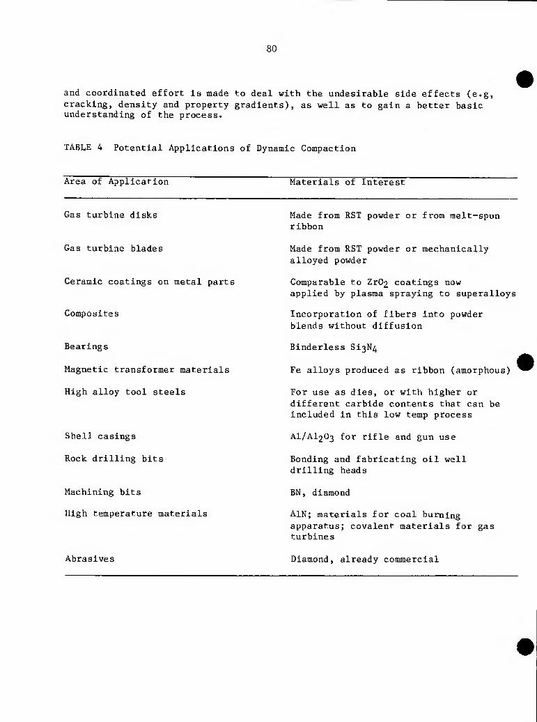
80
and coordinated effort is made to deal with the undesirable side effects (e.g, cracking, density and property gradients), as well as to gain a better basic understanding of the process.
TABLE 4 Potential Applications of Dynamic Compaction
Area of Application Materials of Interest
Gas turbine disks
Gas turbine blades
Ceramic coatings on metal parts
Composites
Bearings
Magnetic transformer materials
High alloy tool steels
Shell casings
Rock drilling bits
Machining bits
High temperature materials
Abrasives
Made from RST powder or from melt-spun ribbon
Made from RST powder or mechanically alloyed powder
Comparable to Zr02 coatings now applied by plasma spraying to superalloys
Incorporation of fibers Into powder blends without diffusion
Blnderless SI3N4
Fe alloys produced as ribbon (amorphous)
For use as dies, or with higher or different carbide contents that can be Included in this low temp process
AI/AI2O3 for rifle and gun use
Bonding and fabricating oil well drilling heads
BN, diamond
AIN; materials for coal burning apparatus; covalent materials for gas turbines
Diamond, already commercial
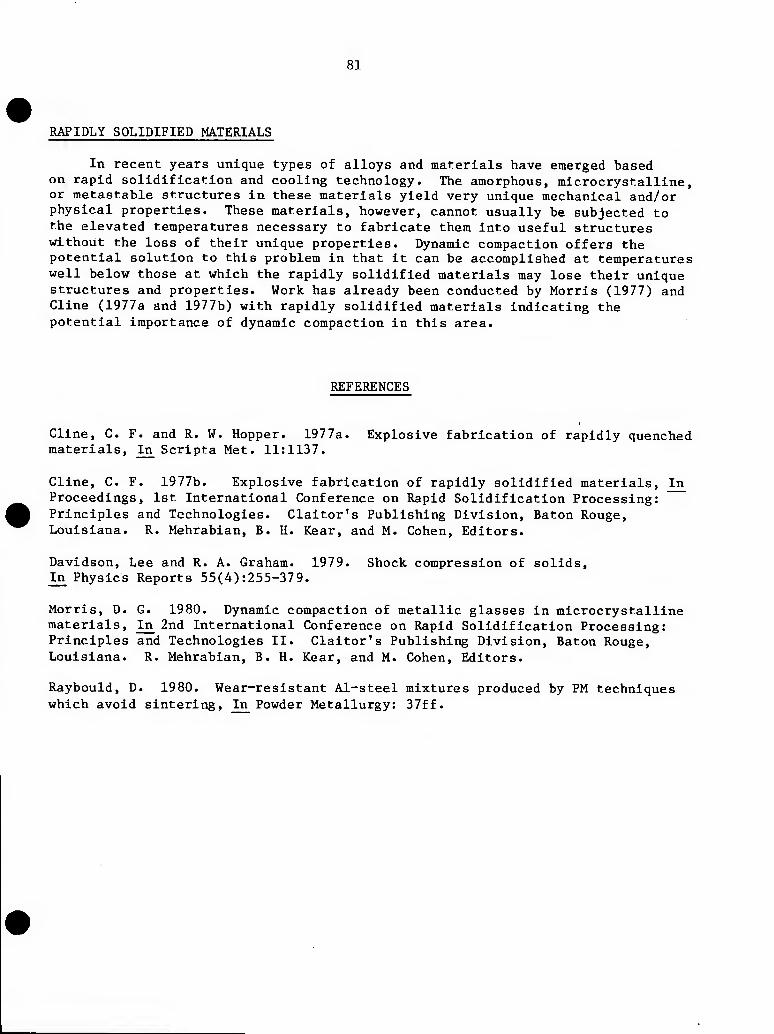
81
RAPIDLY SOLIDIFIED MATERIALS
In recent years unique types of alloys and materials have emerged based on rapid solidification and cooling technology. The amorphous, microcrystalline, or metastable structures in these materials yield very unique mechanical and/or physical properties. These materials, however, cannot usually be subjected to the elevated temperatures necessary to fabricate them into useful structures without the loss of their unique properties. Dynamic compaction offers the potential solution to this problem in that it can be accomplished at temperatures well below those at which the rapidly solidified materials may lose their unique structures and properties. Work has already been conducted by Morris (1977) and Cline (1977a and 1977b) with rapidly solidified materials indicating the potential importance of dynamic compaction in this area.
REFERENCES
Cline, C. F. and R. W. Hopper. 1977a. Explosive fabrication of rapidly quenched materials. In Scripta Met. 11:1137.
Cline, C. F. 1977b. Explosive fabrication of rapidly solidified materials, In Proceedings, 1st International Conference on Rapid Solidification Processing: Principles and Technologies. Claitor's Publishing Division, Baton Rouge, Louisiana. R. Mehrabian, B. H. Kear, and M. Cohen, Editors.
Davidson, Lee and R. A. Graham. 1979. Shock compression of solids. In Physics Reports 55(4):255-379.
Morris, D. G. 1980. Dynamic compaction of metallic glasses in microcrystalline materials, In_ 2nd International Conference on Rapid Solidification Processing: Principles and Technologies II. Claitor's Publishing Division, Baton Rouge, Louisiana. R. Mehrabian, B. H. Kear, and M. Cohen, Editors.
Raybould, D. 1980. Wear-resistant Al-steel mixtures produced by PM techniques which avoid sintering. In Powder Metallurgy: 37ff.
Chapter 9
PROBLEM AREAS
SAFETY
Since the dynamic compaction process is associated with high energy sources, high velocity rates of compaction, and extremely high pressures, there is proper concern about its safety. Although safety must be a prime consideration in utilizing the process, these considerations are neither unreasonably demanding nor limiting to the extent that the use of dynamic compaction procedures would be prevented or become economically unattractive.
Projectile launching guns and high speed forming machines generally can be integrated rather closely with other manufacturing facilities and operations by use of basically standard machine safety procedures.
On the other hand, compaction operations involving explosives require considerably greater safety precautions. These principally involve the need to isolate (often remotely) the compaction operation from all other manufacturing facilities and operations. The procurement, transportation, storage, and handling of the explosives themselves must be done only by well trained and qualified personnel to ensure the safety of the operation. These functions are controlled by existing federal, state, and local laws and regulations.
The site for an explosive compaction operation must be selected and set up so that the blast and debris from the detonating explosive will be contained or not cause any harm to personnel or property. This will most often mean that the site must be remote. Some blast containment chambers and buildings that allow explosive fabrication operations such as compaction to be accomplished close to or actually in other manufacturing facilities have been constructed and are being used (Fling and Linse 1972). These containment structures, however, usually are limited to explosive quantities of approximately 100 pounds or less.
Elevated temperature or hot dynamic compaction with explosives is an operation in which safety cannot be overstressed because of the requirement to place the heated container and material to be densified in extremely close proximity with the explosive. This is accomplished through rapid remote transfer of the heated material into the explosive system and immediate detonation of the explosive. It is a process that should be carried out only by those who are extremely knowledgeable about both explosives and dynamic compaction.
83
84
ENVIRONMENTAL CONCERNS
The most significant environmental concern with respect to dynamic compaction Is noise. The noise level associated with the process generally increases with increasing velocity and/or energy of the operation. In order to reduce the noise level to acceptable levels, it often will be necessary to locate the operation in sound-reducing enclosures or barriers. In the case of explosives, particularly when large quantities are required, remote sites will be required as discussed above.
A second but normally less important environmental concern is the gaseous detonation products of explosives. Although these products contain oxides of carbon and nitrogen, the total quantities generated have a negligible environmental impact.
ECONOMIC CONSIDERATIONS
The economic aspects of dynamic compaction probably have been one of the major deterrents to its commercial acceptance in the United States. In general, dynamic compaction is considerably more expensive than the standard powder consolidation techniques when utilized to fabricate most powder materials and structures. One of the major reasons for this lack of economic competitiveness is associated with the low production rates that thus far have been achieved with dynamic compaction.
The ultimate acceptance of dynamic compaction will be in those applications" in which economic considerations are secondary. This will result when:
1. Large compacts are required that are beyond the size of more standard consolidation capabilities.
2. Unique characteristics or properties in the material resulting from the dynamic compaction process are desired (i.e., fine grain structure, activation for sintering, etc.).
3. Unique characteristics or properties in the starting powder must be retained through the compaction operation (i.e., amorphous structure, fine grain structures, etc.). This is particularly relevant when elevated temperatures cannot be tolerated.
4. Pressures higher than those achievable by standard consolidation techniques are required to compact and densify high strength powdered materials.
GEOMETRIES, SHAPES, SIZES, AND SCALING
Dynamic compaction in general has been limited to the production of components having relatively simple geometries and shapes. These shapes normally include plates (Figure 32) and rods and cylinders (Figure 33) although some slightly more complex components such as the nozzle and hemisphere shown in Figure 33 can be compacted when an internal mandrel having the desired geometry can be employed and subsequently removed after compaction. Explosive compaction is particularly suited for the production of long cyclinders or tubes having large length-to-diameter (L/D) ratios. Machine or gas gun compaction, typically results in the low L/D ratios that are associated with more conventional powder pressing and sintering techniques.
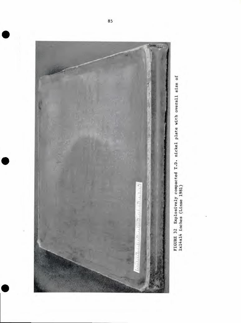
85
86
FIGURE 33 Geometric shapes compacted with explosives: tungsten nozzle (left); T1-6A1-4V cylinder (top); 304 stainless steel hemisphere (right); and Beryllium Rod (bottom) (Linse 1981)
87
In general, dynamically compacted components, particularly those made by explosive compaction, have not been made to near net-shape. Gas gun and/or machine compaction offers the potential for fabricating components to final net shape (Raybould 1980). As with many other aspects of the dynamic compaction process, the real capability to fabricate near-net-shape components has not been investigated to any great extent.
With respect to size, most components fabricated to date are relatively small. For example, most cylindrical samples compacted by explosives are on the order of 1 inch in diameter by 5 to 6 inches long. Titanium and steel alloy cylinders up to 4 inches diameter and 10 inches long have been explosively compacted in the United States (unpublished data on dyanmic compaction from V. D. Linse, Battelle Columbus Laboratories). Compacts in the meter range have been reported but the committee has not been able to verify or substantiate these reports. The largest fully-reported plate or slab compacted by explosives is that shown in Figure 32.
At present compacts made by the gas gun are 2 to 3 inches in diameter and are limited by the size of the guns being used (personal communications from C. F. Cllne, 1981 and D. Raybould, 1981). Guns are available that could produce compacts up to 6 inches in diameter. As was noted earlier in this report, however, these larger guns are predominantly used for elaborately instrumented experimental work, and are not necessarily suited for production type powder compaction.
Almost no information has been reported concerning attempts to scale up the dynamic compaction process to produce larger compacts or to determine size limitations. Before scaling can be seriously addressed, the problems more basic to the process such as cracking, density, property variations, etc., must be more thoroughly understood and solved. As the process is scaled up to produce larger sizes, these problems are expected to become more severe. In addition, the scale ultimately achieveable will be limited to the maximum energy source that can be practically employed. In this case, explosive compaction can be expected to produce much larger products than gas guns and machines. The cost of a gas gun much larger than those presently in existence would be prohibitive.
CRACKING
Crack, formation during the dynamic compaction process is the most serious unresolved technical problem associated with the process. This problem has been observed in almost all dynamically compacted materials with the exception of the very low strength, ductile metals such as pure aluminum and copper. The tendency for crack formation and intensity of cracking increases as the compact approaches theoretical density.
Linse (1981) has identified three basic types of cracking that are encountered in dynamic compaction. These are illustrated in Figure 34 and are described below.
88
Cracks Cracks Cracks
(a) RADIAL (b) TRANSVERSE (c) SPIRAL
FIGURE 34 Types of cracking encountered in dynamic compaction: (a) radial, (b) transverse, (c) spiral
89
In cylindrical compacts, radial cracks are found radiating from the center axis of the compact (Figure 34a). They are a result of excessive compaction energy in the compressive shock wave converging on the central axis. At the central axis, the compressive wave reflects as a tensile wave causing the crack formation. If the compressive wave intensity is sufficient, melting can occur along the central axis, often accompanied by a hole along the axis. The hole is a further indication that the interacting shock is of such intensity that it forms an extremely high pressure region along the central axis that is known as "mach disk" or "mach stem."
Radial cracking most often can be eliminated by reducing the energy and pressure input into the compact to a level such that it dissipates just as it reaches the center axis of the compact. The precise establishment of the energy and pressure levels required to achieve a uniform and fully dense, crack free cylindrical compact is difficult.
Transverse cracking (Figure 34b) occurs in both cylindrical and flat plate compacts. It results from tensile stress and longitudinal movement Induced during compaction. In flat plate compacts, it also can result from lateral movement of the compact. When the tensile stress and movement occur, the compacted powder material does not have sufficient strength or ductility to accommodate the stress and movement. This type of cracking often can be eliminated by providing better edge and end constraints on the powder during compaction.
Spiral cracking (Figure 34c) is the most unique and potentially the most severe, particularly when scale-up is attempted. It occurs in cylindrical compaction and tends to increase in severity as the inherent brittleness of the material being compacted increases. During cylindrical compaction, densification or compaction progresses from the outer surface of the cylinder into the central axis. The outer portion of the compact which densifies first must continue to move inward to accommodate the densification of the inner portion of the compact. If the densifled region does not have the ability to uniformly plastically flow as it moves inward at a high velocity, it forms shear cracks. In order to maintain their orientation to the progressing compaction front, they spiral inward to the center and along the length of the cylinder at a compound angle. The elimination of this type of cracking has not been resolved fully although hot or elevated temperature compaction has successfully eliminated it in a number of high strength metal alloys that are highly susceptable to spiral-shear cracking when cold compacted (V. D. Linse 1981).
90
ENERGY SOURCE CONSISTENCY
Much of the information from past work on explosive compaction has been inconsistent, with little ability to be correlated retrospectively. The committee believes that this is caused primarily by inconsistency of the energy source—the explosive. Most explosives used for dynamic compaction are classified as nonideal explosives. The explosives are complex and are difficult to understand and control from a performance viewpoint. As a result, very few individuals are capable of utilizing these explosives in a manner that yields the desired, consistent, and predictable energy input into the powder compact with the desired, consistent, and predictable results. It is imperative that those working with explosive compaction make every effort to more thoroughly understand and properly use the explosive so as to produce consistent results.
REFERENCES
Fling, R. S. and V. D. Linse. 1982. Design and operation of a blast containment structure, ^Behaviour and Utilization of Explosives in Engineering Design. ASME: New Mexico. L. Davison and J. E. Kremely, Editors.
Linse, V. D. 1981. Explosive compaction at Battelle Columbus. Presented at the Materials Research Council meeting. La Jolla, California.
Raybould, D. 1981. The production of strong parts and non-equilibrium alloys by dynamic compaction. In Shock Waves and High Strain-Rate Phenomena in Metals, Plenum Press. Marc A. Meyers and Lawrence E. Murr, Editors.


![Effect of sintering temperature on microstructure and electrical ... · sintered SrBi 2Ta 2O 9 ceramic was reported [30]. Hydrothermal synthesis of ceramic powders has gained considerable](https://img.pdfslide.us/doc/110x75/5e4c4aff753cfb3ad22691fb/effect-of-sintering-temperature-on-microstructure-and-electrical-sintered-srbi.jpg)