Embed Size (px)
Citation preview
Dynamic Communication across Supply Chain Services
A thesis submitted for the degree of
Doctor of Philosophy
Manish Malhotra M.Eng (I.T)
Student Id: 2011269M
School of Electrical and Computer Engineering
Science, Engineering, and Technology Portfolio,
RMIT University,
Melbourne, Victoria, Australia.
September 21, 2009

Declaration
I certify that except where due acknowledgement has been made, the work is that of the author
alone; the work has not been submitted previously, in whole or in part, to qualify for any other academic award; the content of the thesis is the result of work which has been carried out since
the official commencement date of the approved research program; and, any editorial work, paid
or unpaid, carried out by a third party is acknowledged.
Manish Malhotra School of Electrical and Computer Engineering
RMIT University
September 21, 2009

Acknowledgments
I express my deepest and sincere gratitude to my supervisor Professor Andrew Jennings and
Professor Mohini Singh for their support, invaluable guidance and motivation over the years. Their constant effort to keep me on track is highly appreciated without which this thesis would
not have been possible. They have been excellent mentors and good friends to support me
throughout my thesis.
I am thankful to Professor Zahir Tari for allowing me to work with him for ARC (Australian
Research Council) Linkage grants at the School of Computer Science and IT at RMIT University.
I would like to thank the School of Electrical and Computer Engineering, RMIT University and
Professor Andrew Jennings for providing me an opportunity to conduct research at the School.
Sincere thanks go to my work colleagues and fellow PhD students for their many interesting
discussions and help in making the work environment friendly and enjoyable. In particular,
thanks to the staff of RMIT for their valuable comments.
My gratitude to my parents S.S Malhotra and C.K Malhotra for their many years of hard work
and sacrifices they have made to support me.
Finally, a very special thanks to my daughter Prisha Malhotra and my wife Parul Malhotra for
their love, patience and for always being supportive to me

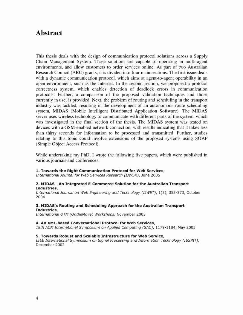
Abstract
This thesis deals with the design of communication protocol solutions across a Supply
Chain Management System. These solutions are capable of operating in multi-agent
environments, and allow customers to order services online. As part of two Australian
Research Council (ARC) grants, it is divided into four main sections. The first issue deals
with a dynamic communication protocol, which aims at agent-to-agent operability in an
open environment, such as the Internet. In the second section, we proposed a protocol
correctness system, which enables detection of deadlock errors in communication
protocols. Further, a comparison of the proposed validation techniques and those
currently in use, is provided. Next, the problem of routing and scheduling in the transport
industry was tackled, resulting in the development of an autonomous route scheduling
system, MIDAS (Mobile Intelligent Distributed Application Software). The MIDAS
server uses wireless technology to communicate with different parts of the system, which
was investigated in the final section of the thesis. The MIDAS system was tested on
devices with a GSM-enabled network connection, with results indicating that it takes less
than thirty seconds for information to be processed and transmitted. Further, studies
relating to this topic could involve extensions of the proposed systems using SOAP
(Simple Object Access Protocol).
While undertaking my PhD, I wrote the following five papers, which were published in
various journals and conferences:
1. Towards the Right Communication Protocol for Web Services, International Journal for Web Services Research (IJWSR), June 2005
2. MIDAS - An Integrated E-Commerce Solution for the Australian Transport Industries, International Journal on Web Engineering and Technology (IJWET), 1(3), 353-373, October 2004
3. MIDAS’s Routing and Scheduling Approach for the Australian Transport Industries, International OTM (OntheMove) Workshops, November 2003
4. An XML-based Conversational Protocol for Web Services, 18th ACM International Symposium on Applied Computing (SAC), 1179-1184, May 2003
5. Towards Robust and Scalable Infrastructure for Web Service, IEEE International Symposium on Signal Processing and Information Technology (ISSPIT), December 2002

Contents:
Chapter 1: Introduction
1.1 Supply chain management system………………………………………...1
1.2 Scope of the project………………………………………...……………….4 1.2.1 E-Procurement…...………………………………………………………………........4
1.2.2 Logistics Exchanges…………………………………………………………...….......6
1.3 Issue-I Designing Communication Protocol………………………………..7
1.3.1 Background…………………………………………………………………………...8
1.3.2 Issues during designing protocols……………………………………………...…….10
1.3.3 Aim of the Project……………………………………………………..…………….11
1.4 Issue-II Protocol Correctness………………………………………..13 1.4.1 Background……………………………………………………………...…………...14
1.4.2 Issues involved during protocol correctness…………………………………………19
1.4.3 Aim of the Project……………………………………………………………………22
1.5 Issue-III Routing and Scheduling…………………………...………23 1.5.1 Background…………………………………………………………………………..23
1.5.2 Issues involved during Routing and Scheduling….…………………………………26
1.5.3 Aim of the Project……………………………………………………………………29
1.6 Issue-IV Wireless……………………………...…………………….31 1.6.1 Background………………………………………………………………………….31
1.6.2 Issues related to Wireless module...........................…………………………………34
1.6.3 Aim of the Project……………………………………………………………………37
Chapter 2: Designing Communication Protocol
2.1 Related works………………………………………………………..40 2.1.1 Agents Frameworks………………………………………………………………….40
2.1.2 Agent Communication Language and FIPA….……………………………………..42
2.1.3 Conversation rules…………………………………………………………………...44
2.1.4 Internet interoperability……………………………………………………………...46
2.1.5 Ontology……………………………………………………………………………..48
2.2.1 State Machines………………………………………………………49 2.2.2 Protocol Correctness…………………………………………………………………56
2.2.3 State Explosion………………………………………………………………………59
2.3.4 Invalid State Machines………………………………………………………………63
2.2.5 Ontological data………………………………………………………………….…..64
2.2.6 Similarity Matching…………………………………………………………………65
2.3 Implementation..……………………… ……………………………72 2.3.1 Buying behavior……………………………………………………………………..72
2.3.2 Vocabulary…………………………………………………………………………...74
2.3.3 Architecture………………………………………………………………………….76
2.3.4 Catalog Negotiation Protocol………………………………………………………..77

2.3.5 Merchant Protocols………………………………………………………………….81
2.3.6 Client Agent………………………………………………………………………....92
2.3.7 Client Parameters…..………………………………………………………………..92
2.3.8 Vocabulary Implementation…………………………………………………….…...93
2.3.9 State Machine Processing…………………………………………………………...94
2.3.10 XML Parsing………………………………………………………………………97
2.4 Testing…………………….…..…………………………………..98 2.4.1 State Machine Correctness…………………………………………………………98
2.4.2 Product Brokering………………………………………………………………….100
2.4.3 Individual Protocol Testing………………………………………………………...104
2.4.4 Merchant Brokering………………………………………………………………..109
Chapter 3: Protocol Validation for CCSMs
3.1 Related works……………………………………………………....113 3.1.1 Exhaustive Exploration Techniques………………………………….….116
3.1.2 Partial Exploration Techniques………………………………………......123
3.2 CCSM……………………………………………………………...130 3.2.1 Complex state machines……………………………………………………………130
3.2.2 Communicating Complex State Machines…………..……………………………..132
3.2.3 Advantages of CCSM Model……………………………………...……………….133
3.2.4 Protocol Errors……………………………………………………………………...135
3.2.5 Protocol Validation…………………………………………...…………………….136
3.3 Implementation…………………………………………………….143 3.3.1 XML specification………………………………………………………………….143
3.3.2 XML Parsing……………………………………………………………………….146
3.3.3 Class Description…………………………………………………………………...149
3.3.4 Analysis………………………………………………..…………………….…..…150
Chapter 4: Routing and Scheduling
4.1 Related works……………………………… ………………….….155
4.1.1 Vehicle Routing Problem…………………… …………………....155 4.1.1.1 Mathematical Formulation………………………………………………………..156
4.1.1.2 Insertion Heuristic………………………………………………………………..158
4.1.1.3 Genetic Algorithm………………………………………………………………..159
4.1.2 Digital Maps………………………………………………………160 4.1.2.1 OpenMap…………………………………………………………………….…161
4.1.2.2 Map Data…………………………………………………………………….…162
4.1.3 SMS……………………………………………………………....162 4.1.3.1 SMS Access…………………………………………………………………….162
4.2.1 MIDAS………………………………………………...………....163 4.2.1.1 MIDAS Functional Overview………………………………………………….164
4.2.1.2 MIDAS Processes………………………………………………………………164
4.2.1.3 MIDAS Technical Architecture……………………………………..…………165
4.2.1.4 MIDAS modules………………………………………………………………..168
4.2.2 MIDAS Server…………………………………………………...168 4.2.2.1 Specification……………………………………………………………………169
4.2.2.2 Design…………………………………………………………………………..172
4.3.1 Implementation…………………………………………………..179 4.3.1.1 Communication………………………………………………………………...179
4.3.1.2 Routing………………………………………………………………………...181
4.3.1.3 Scheduling……………………………………………………………………..186
4.3.2 Testing……………………………………………………………..187 4.3.2.1 Functional Testing…………………………………………………………………187
4.3.2.2 Performance Testing……………………………………………………………….189
Chapter 5: Wireless
5.1 Related Works…………………………………………………….. 193 5.1.1 Identification of stakeholders………………………………………….. .193
5.1.2 Functional Requiremnets……………………………………………....194 5.1.2.1 Requirements for handheld application…………………………………….….194
5.1.2.2 Requirement for handheld conduit………………………………………….….195
5.1.2.3 Requirement for Desktop Application………………………………………....195
5.1.2.4 Requirement for WAP Application……………………………………………195 5.1.3 Non Functional Requirements…………………………………......196 5.1.3.1 Handheld application…………………………………………………………..196
5.1.3.2 Handheld conduit………………………………………………………………196
5.2 System Architecture and Design………………………………...…196 5.2.1 Overall system architecture……………………….…………………………….196
5.2.2 Handheld application design……………………………………………………198
5.2.3 Use Cases ……………………………………………………………………….200
5.2.4 Component Diagram ……………………………………………………………201
5.2.5 Communication protocol and message format …………………………………203
5.2.6 Error Handling Protocol…………………………………………………….......206
5.3 Handheld conduit design……………………………………….…..207 5.3.1 Use Cases …………………………………………………………………………..211
5.3.2 Class Diagram ……………………………………………………………………...212
5.4 Desktop application design………………………………………...212 5.4.1 Use Cases …………………………………………………………………………..213
5.4.2 Class Diagram ……………………………………………………………………...213
5.5 WAP application design…………………………………………....214 5.5.1 Use Cases …………………………………………………………………………..215
5.5.2 Component Diagram ……………………………………………………………….216
5.6 System Implementation ……………………………………………217 5.6.1 C Programming language ………………………………………………………….217 5.6.2 PilRC Programming language ……………………………………………………..217
5.6.3 Java Programming language ……………………………………………………….218
5.6.4 VB Programming language ………………………………………………………..219

5.6.5 PRC-Tools …………………………………………………………………………219
5.6.6 PilRC compiler …………………………………………………………………….219
5.6.7 Palm OS Software Development Kit ………………………………………………219
5.6.8 Conduit Development Kit ………………………………………………………….219
5.6.9 Microsoft Visual .Net with Mobile Internet Framework …………………………..220
5.7 Testing…………………………………………………………...…220 5.7.1 Handheld Application testing ……………………………………………………..220
5.7.2 Handheld conduit testing …………………………………………………………..226
5.7.3 Desktop Application testing ………………………………………………………227
5.7.4 WAP Application testing …………………………………………………………..228
Chapter 6: Conclusion…………………………………………………..230
6.1 Conclusion…………………………………………………………230 6.1.1 Dynamic Communication Protocol…………………………………………….……….230
6.1.2 Protocol Correctness…………………………………………………………………....233
6.1.3 Routing and Scheduling……………………………………………………….……......234 6.1.4 Wireless…………………………………………………………………………………235
6.2 Future Work…………………………………………………….….237 6.2.1 Dynamic Communication Protocol……………………………………………...……...237
6.2.2 Routing and Scheduling……………………………………………………….........….238
6.2.3 Wireless………………………………………………………………………….........239
Chapter 7: References…………………………………………………...240
Appendices Appendix A: Description of implemented Java classes …………………………………...247
Appendix B: Testing – scenario for various types of deadlocks …………………………...251
Appendix C: MIDAS Class Diagrams ……………………………………………….........260
Appendix D: Summary of individual classes in Java – MIDAS …………………………...269
Appendix E: Communications packet data structure …………………………………......273
Appendix F: Class Diagrams ………………………………………………………………274
Appendix G: XML listings…………………………………………………………………277
Appendix H: Sequence and class diagrams related to MIDAS ……………………………283

Figure Index
Chapter1
1.1 Overall Supply chain from raw material to finished products………….2
1.2 Flow of Information and Goods throughout supply chain………………3
1.3 Issues in E-procurement and Logistics Exchanges……………………….7
1.4 A communicating finite state machine……………………………………18
1.5 Two CFSMs communicating through channels………………………….19
1.6 Architecture of MIDAS……………………………………………………..26
1.7 Screen shot of the system operator interface with vehicle locations
in Melbourne metropolitan area…………………………………………..28
1.8 Overview of the software…………………………………………………...33
1.9 Handheld application combo box………………………………………….38
Chapter 2
2.1 Just-In-Time State Machine…………………………………………………….51
2.2 Process P state machine for Reachability Analysis………………....................56
2.3 Process Q state machine for Reachability Analysis……………………………56
2.4 Global State Representation…………………………………………………….57
2.5 Fragment of reachability graph for state machines defined in Fig 2-2............58
2.6 (a) State Diagrams………………………………………………………….63
2.6 (b) State Diagrams………………………………………………………….63
2.6 (c) State Diagrams………………………………………………………….63
2.6 (d) State Diagrams………………………………………………………….63
2.7 (a) Invalid State Machine Example………………………………………64
2.7 (b) Invalid State Machine Example………………………………………64
2.8 Similarity Equation………………………………………………………………67
2.9 Hierarchical Car parts example………………………………….....………….68
2.10 (a) Similarity calculation for two Wine items…………………………...……..79
2.10 (b) Wine catalog fragment ...........................................................80
2.11 Shopfront Protocol State Transition Diagram………………………………...81
2.12 State Transistion Diagram for Haggle Protocol ………………….…………83
2.13 State Transition diagram for English Auction Protocol……………..……...87
2.14 Client Vocabulary implementation of Bid…………………………..…….….94
2.15 XML Messaging Architecture………….……………………….……..………97
2.16 Forward Reachability error in Client state machine…….…………………..99
2.17 Backward reachability error in Client state machine……………..….……100
2.18 Product Brokering Test Display………………………………………..……104
2.19 Shopfront Buy Scenario Test Display………………………………..………105
2.20 Haggle Protocol Test Scenarios………………………………………..…….107
2.21 English Auction Protocol Buy Scenario Display………………………...…..109
2.22 Merchant Brokering………………………………………………………..…111
Chapter 3
3.1 An incorrect communication system…………………………………………...117
3.2 Reachability tree for the communication system of Figure 1…………………118
3.3 An example of balanced protocol………………………………………………119
3.4 The structural partitions for a balanced protocol……………………………..119
3.5 A communication system with two entities……………………………………121
3.6 Tree protocol for process1………………………………………………………122
3.7 Tree protocol for process2………………………………………………………122
3.8 Maximal Progress State Exploration…………………………………………...125
3.9 A two-process protocol for reverse reachability analysis……………………...127
3.10 Simultaneous reachability analysis………………………………………………128
3.11 A sample CSM Agent with two complex states registration & Bidding……...131
3.12 CCSMs M1 and M2 communicating over channels C12 and C21……………..134
3.13 Possible deadlock states Procedure……………………………………………..138
3.14 Deadlock detection algorithm……………………………………………………140
3.15 Backtracking module……………………………………………………………..142
3.16 Top level view of a CCSM………………………………………………………..144
3.17 An internal FSM…………………………………………………………………..144

3.18 DTD for state machine specification……………………………………………..144
3.19 First example of a communication system………………………………………151
3.20 Second example showing establishment/clear procedure in X.25……………...152
3.21 Third example showing alternating bit protocol………………………………..153
Chapter 4
4.1 An example solution to a Vehicle Routing Problem…………………………….156
4.2 Screen shot of Sydney digital map……………………………………………….161
4.3 Overview of OpenMap architecture…………………………………………...161
4.4 Telstra SMS Access Manager - SMPP Access [11]……………………………..163
4.5 Functional Overview of MIDAS…………………………………………………164
4.6 MIDAS Processes…………………………………………………………………165
4.7 MIDAS Technical Architecture………………………………………………….166
4.8 Interaction between MIDAS and MIDAS external entities…………………….173
4.9 Communication packet data structure…………………………………………..179
4.10 Double layer trees…………………………………………………………………181
4.11 Closest points nomination………………………………………………………...182
4.12 Screen shot of the vehicle route from Werribee to Queenscliff and Anglesea...185
4.13 Screen shot of the result of the performance test case………………………….191
4.14 Time trend against the order growth in scheduling…………………….………191
Chapter 5
5.1 Handheld database layout………………………………………………………..199
5.2 Handheld record layouts………………………………………………………….200
5.3 Handheld application use cases…………………………………………………..200
5.4 Palm application code sections…………………………………………………...202
5.5 HotSync components relationship……………………………………………….207
5.6 Overview of the process flow through the components………….………….….208
5.7 Handheld conduit use cases……………………………………………………...211
5.8 Handheld conduit class diagrams……………………………………………….212
5.9 Desktop application use cases…………………………………………………...213
5.10 Desktop application class diagram………………………………………………213
5.11 WAP programming architecture………………………………………………..214
5.12 WAP application use cases……………………………………………………….216
5.13 WAP application component diagram…………………………………………..216
Table Index
Chapter 2
2.1 (a) Describes KQML code fragment…………………………………………..43
2.1 (b) Sibling Similarity Example………………………………………………...67
2.2 Dissimilarity values example………………………………………………………68
2.3 Example Feature Values of Car Parts…………………………………………….69
2.4 Feature Vector example for Tyre T1……………………………………………...69
2.5 Feature Vector example for Tyre T2………………………………………….70
2.6 Similarity calculation for T1 and T2………………………………………………70
2.7 Feature Vector example for Tyre T2……………………………………………...70
2.8 Feature Vector example for Brake B3………………………………………...70
2.9 Similarity calculation for T2 and B3………………………………………………71
2.10 Similarity calculation example for T2 and W2…………………………………...71
2.11 Penfold’s 1996 Kalimna Bin28 Shiraz feature vector……………………………78
2.12 Wynns’s 1993 Hermitage Shiraz feature vector………………………….………78
2.13 FSM Message table for Shopfront Protocol………………………………………82
2.14 FSM Message table for Haggle Protocol………………………………………….84
2.15 FSM Message table for English Auction Protocol………………………………..88
2.16 Client Agent parameters…………………………………………………………...92
2.17 State Machine XML elements……………………………………………………..94
2.18 Client parameters for Product Brokering test………………………………….101
2.19 Keyword Query for Product Brokering test…………………………………….102
2.20 Catalog Items (1) returned from Product Brokering…………………………...102
2.21 Reference Query for Product Brokering………………………………………...103
2.22 Catalog Items (2) returned from Product Brokering…………………………...103
2.23 Shopfront Protocol Test Scenarios……………………………………………….105
2.24 Haggle Protocol Test Scenarios…………………………………………………..106
2.25 English Auction Test Scenarios…………………………………………………..108
2.26 URLs for Merchant Brokering Test……………………………………………..110
2.27 Client parameters for Merchant Brokering Test……………………………….110
2.28 Product Brokering results for Merchant Brokering……………………………110
2.29 Merchant Brokering transaction………………………………………………...111
Chapter 3
3.1 Elements and attributes of an XML state machine……………………………..145
3.2 Java Classes Description………………………………………………………….149
3.3 Comparison of performance with existing algorithms…………………………153
Chapter 5
5.1 XML tags conversion table……………………………………………………….204
5.2 Server error code………………………………………………………………….206
5.3 Records synchronization logic……………………………………………………209
5.4 Difference between standard C and Palm OS C………………………………...218
5.5 Test cases and their actual and final results…………………………….……….221
5.6 Results of validation testing………………………………………………………222
5.7 Results of functionality testing…………………………………………………...226
5.8 Functionality testing results for Desktop application testing………………......227
5.9 Functionality testing results for WAP application testing……………………...228

1
Dynamic Communication across Supply Chain Services
A thesis submitted for the degree of
Doctor of Philosophy
Manish Malhotra M.Eng (I.T)
Student Id: 2011269M
School of Electrical and Computer Engineering
Science, Engineering, and Technology Portfolio,
RMIT University,
Melbourne, Victoria, Australia.
September 21, 2009

2
Declaration
I certify that except where due acknowledgement has been made, the work is that of the author
alone; the work has not been submitted previously, in whole or in part, to qualify for any other academic award; the content of the thesis is the result of work which has been carried out since
the official commencement date of the approved research program; and, any editorial work, paid
or unpaid, carried out by a third party is acknowledged.
Manish Malhotra School of Electrical and Computer Engineering
RMIT University
September 21, 2009

3
Acknowledgments
I express my deepest and sincere gratitude to my supervisor Professor Andrew Jennings and
Professor Mohini Singh for their support, invaluable guidance and motivation over the years. Their constant effort to keep me on track is highly appreciated without which this thesis would
not have been possible. They have been excellent mentors and good friends to support me
throughout my thesis.
I am thankful to Professor Zahir Tari for allowing me to work with him for ARC (Australian
Research Council) Linkage grants at the School of Computer Science and IT at RMIT University.
I would like to thank the School of Electrical and Computer Engineering, RMIT University and
Professor Andrew Jennings for providing me an opportunity to conduct research at the School.
Sincere thanks go to my work colleagues and fellow PhD students for their many interesting
discussions and help in making the work environment friendly and enjoyable. In particular,
thanks to the staff of RMIT for their valuable comments.
My gratitude to my parents S.S Malhotra and C.K Malhotra for their many years of hard work
and sacrifices they have made to support me.
Finally, a very special thanks to my daughter Prisha Malhotra and my wife Parul Malhotra for
their love, patience and for always being supportive to me
4
Abstract
This thesis deals with the design of communication protocol solutions across a Supply
Chain Management System. These solutions are capable of operating in multi-agent
environments, and allow customers to order services online. As part of two Australian
Research Council (ARC) grants, it is divided into four main sections. The first issue deals
with a dynamic communication protocol, which aims at agent-to-agent operability in an
open environment, such as the Internet. In the second section, we proposed a protocol
correctness system, which enables detection of deadlock errors in communication
protocols. Further, a comparison of the proposed validation techniques and those
currently in use, is provided. Next, the problem of routing and scheduling in the transport
industry was tackled, resulting in the development of an autonomous route scheduling
system, MIDAS (Mobile Intelligent Distributed Application Software). The MIDAS
server uses wireless technology to communicate with different parts of the system, which
was investigated in the final section of the thesis. The MIDAS system was tested on
devices with a GSM-enabled network connection, with results indicating that it takes less
than thirty seconds for information to be processed and transmitted. Further, studies
relating to this topic could involve extensions of the proposed systems using SOAP
(Simple Object Access Protocol).
While undertaking my PhD, I wrote the following five papers, which were published in
various journals and conferences:
1. Towards the Right Communication Protocol for Web Services, International Journal for Web Services Research (IJWSR), June 2005
2. MIDAS - An Integrated E-Commerce Solution for the Australian Transport Industries, International Journal on Web Engineering and Technology (IJWET), 1(3), 353-373, October 2004
3. MIDAS’s Routing and Scheduling Approach for the Australian Transport Industries, International OTM (OntheMove) Workshops, November 2003
4. An XML-based Conversational Protocol for Web Services, 18th ACM International Symposium on Applied Computing (SAC), 1179-1184, May 2003
5. Towards Robust and Scalable Infrastructure for Web Service, IEEE International Symposium on Signal Processing and Information Technology (ISSPIT), December 2002
5
Contents:
Chapter 1: Introduction
1.1 Supply chain management system………………………………………...1
1.2 Scope of the project………………………………………...……………….4 1.2.1 E-Procurement…...………………………………………………………………........4
1.2.2 Logistics Exchanges…………………………………………………………...….......6
1.3 Issue-I Designing Communication Protocol………………………………..7
1.3.1 Background…………………………………………………………………………...8
1.3.2 Issues during designing protocols……………………………………………...…….10
1.3.3 Aim of the Project……………………………………………………..…………….11
1.4 Issue-II Protocol Correctness………………………………………..13 1.4.1 Background……………………………………………………………...…………...14
1.4.2 Issues involved during protocol correctness…………………………………………19
1.4.3 Aim of the Project……………………………………………………………………22
1.5 Issue-III Routing and Scheduling…………………………...………23 1.5.1 Background…………………………………………………………………………..23
1.5.2 Issues involved during Routing and Scheduling….…………………………………26
1.5.3 Aim of the Project……………………………………………………………………29
1.6 Issue-IV Wireless……………………………...…………………….31 1.6.1 Background………………………………………………………………………….31
1.6.2 Issues related to Wireless module...........................…………………………………34
1.6.3 Aim of the Project……………………………………………………………………37
Chapter 2: Designing Communication Protocol
2.1 Related works………………………………………………………..40 2.1.1 Agents Frameworks………………………………………………………………….40
2.1.2 Agent Communication Language and FIPA….……………………………………..42
2.1.3 Conversation rules…………………………………………………………………...44
2.1.4 Internet interoperability……………………………………………………………...46
2.1.5 Ontology……………………………………………………………………………..48
2.2.1 State Machines………………………………………………………49 2.2.2 Protocol Correctness…………………………………………………………………56
2.2.3 State Explosion………………………………………………………………………59
2.3.4 Invalid State Machines………………………………………………………………63
2.2.5 Ontological data………………………………………………………………….…..64
2.2.6 Similarity Matching…………………………………………………………………65
2.3 Implementation..……………………… ……………………………72 2.3.1 Buying behavior……………………………………………………………………..72
2.3.2 Vocabulary…………………………………………………………………………...74
2.3.3 Architecture………………………………………………………………………….76
2.3.4 Catalog Negotiation Protocol………………………………………………………..77
6
2.3.5 Merchant Protocols………………………………………………………………….81
2.3.6 Client Agent………………………………………………………………………....92
2.3.7 Client Parameters…..………………………………………………………………..92
2.3.8 Vocabulary Implementation…………………………………………………….…...93
2.3.9 State Machine Processing…………………………………………………………...94
2.3.10 XML Parsing………………………………………………………………………97
2.4 Testing…………………….…..…………………………………..98 2.4.1 State Machine Correctness…………………………………………………………98
2.4.2 Product Brokering………………………………………………………………….100
2.4.3 Individual Protocol Testing………………………………………………………...104
2.4.4 Merchant Brokering………………………………………………………………..109
Chapter 3: Protocol Validation for CCSMs
3.1 Related works……………………………………………………....113 3.1.1 Exhaustive Exploration Techniques………………………………….….116
3.1.2 Partial Exploration Techniques………………………………………......123
3.2 CCSM……………………………………………………………...130 3.2.1 Complex state machines……………………………………………………………130
3.2.2 Communicating Complex State Machines…………..……………………………..132
3.2.3 Advantages of CCSM Model……………………………………...……………….133
3.2.4 Protocol Errors……………………………………………………………………...135
3.2.5 Protocol Validation…………………………………………...…………………….136
3.3 Implementation…………………………………………………….143 3.3.1 XML specification………………………………………………………………….143
3.3.2 XML Parsing……………………………………………………………………….146
3.3.3 Class Description…………………………………………………………………...149
3.3.4 Analysis………………………………………………..…………………….…..…150
Chapter 4: Routing and Scheduling
4.1 Related works……………………………… ………………….….155
4.1.1 Vehicle Routing Problem…………………… …………………....155 4.1.1.1 Mathematical Formulation………………………………………………………..156
4.1.1.2 Insertion Heuristic………………………………………………………………..158
4.1.1.3 Genetic Algorithm………………………………………………………………..159
4.1.2 Digital Maps………………………………………………………160 4.1.2.1 OpenMap…………………………………………………………………….…161
4.1.2.2 Map Data…………………………………………………………………….…162
4.1.3 SMS……………………………………………………………....162 4.1.3.1 SMS Access…………………………………………………………………….162
4.2.1 MIDAS………………………………………………...………....163 4.2.1.1 MIDAS Functional Overview………………………………………………….164
4.2.1.2 MIDAS Processes………………………………………………………………164

7
4.2.1.3 MIDAS Technical Architecture……………………………………..…………165
4.2.1.4 MIDAS modules………………………………………………………………..168
4.2.2 MIDAS Server…………………………………………………...168 4.2.2.1 Specification……………………………………………………………………169
4.2.2.2 Design…………………………………………………………………………..172
4.3.1 Implementation…………………………………………………..179 4.3.1.1 Communication………………………………………………………………...179
4.3.1.2 Routing………………………………………………………………………...181
4.3.1.3 Scheduling……………………………………………………………………..186
4.3.2 Testing……………………………………………………………..187 4.3.2.1 Functional Testing…………………………………………………………………187
4.3.2.2 Performance Testing……………………………………………………………….189
Chapter 5: Wireless
5.1 Related Works…………………………………………………….. 193 5.1.1 Identification of stakeholders………………………………………….. .193
5.1.2 Functional Requiremnets……………………………………………....194 5.1.2.1 Requirements for handheld application…………………………………….….194
5.1.2.2 Requirement for handheld conduit………………………………………….….195
5.1.2.3 Requirement for Desktop Application………………………………………....195
5.1.2.4 Requirement for WAP Application……………………………………………195 5.1.3 Non Functional Requirements…………………………………......196 5.1.3.1 Handheld application…………………………………………………………..196
5.1.3.2 Handheld conduit………………………………………………………………196
5.2 System Architecture and Design………………………………...…196 5.2.1 Overall system architecture……………………….…………………………….196
5.2.2 Handheld application design……………………………………………………198
5.2.3 Use Cases ……………………………………………………………………….200
5.2.4 Component Diagram ……………………………………………………………201
5.2.5 Communication protocol and message format …………………………………203
5.2.6 Error Handling Protocol…………………………………………………….......206
5.3 Handheld conduit design……………………………………….…..207 5.3.1 Use Cases …………………………………………………………………………..211
5.3.2 Class Diagram ……………………………………………………………………...212
5.4 Desktop application design………………………………………...212 5.4.1 Use Cases …………………………………………………………………………..213
5.4.2 Class Diagram ……………………………………………………………………...213
5.5 WAP application design…………………………………………....214 5.5.1 Use Cases …………………………………………………………………………..215
5.5.2 Component Diagram ……………………………………………………………….216
5.6 System Implementation ……………………………………………217 5.6.1 C Programming language ………………………………………………………….217 5.6.2 PilRC Programming language ……………………………………………………..217
5.6.3 Java Programming language ……………………………………………………….218
5.6.4 VB Programming language ………………………………………………………..219
8
5.6.5 PRC-Tools …………………………………………………………………………219
5.6.6 PilRC compiler …………………………………………………………………….219
5.6.7 Palm OS Software Development Kit ………………………………………………219
5.6.8 Conduit Development Kit ………………………………………………………….219
5.6.9 Microsoft Visual .Net with Mobile Internet Framework …………………………..220
5.7 Testing…………………………………………………………...…220 5.7.1 Handheld Application testing ……………………………………………………..220
5.7.2 Handheld conduit testing …………………………………………………………..226
5.7.3 Desktop Application testing ………………………………………………………227
5.7.4 WAP Application testing …………………………………………………………..228
Chapter 6: Conclusion…………………………………………………..230
6.1 Conclusion…………………………………………………………230 6.1.1 Dynamic Communication Protocol…………………………………………….……….230
6.1.2 Protocol Correctness…………………………………………………………………....233
6.1.3 Routing and Scheduling……………………………………………………….……......234 6.1.4 Wireless…………………………………………………………………………………235
6.2 Future Work…………………………………………………….….237 6.2.1 Dynamic Communication Protocol……………………………………………...……...237
6.2.2 Routing and Scheduling……………………………………………………….........….238
6.2.3 Wireless………………………………………………………………………….........239
Chapter 7: References…………………………………………………...240
Appendices Appendix A: Description of implemented Java classes …………………………………...247
Appendix B: Testing – scenario for various types of deadlocks …………………………...251
Appendix C: MIDAS Class Diagrams ……………………………………………….........260
Appendix D: Summary of individual classes in Java – MIDAS …………………………...269
Appendix E: Communications packet data structure …………………………………......273
Appendix F: Class Diagrams ………………………………………………………………274
Appendix G: XML listings…………………………………………………………………277
Appendix H: Sequence and class diagrams related to MIDAS ……………………………283
9
Figure Index
Chapter1
1.1 Overall Supply chain from raw material to finished products………….2
1.2 Flow of Information and Goods throughout supply chain………………3
1.3 Issues in E-procurement and Logistics Exchanges……………………….7
1.4 A communicating finite state machine……………………………………18
1.5 Two CFSMs communicating through channels………………………….19
1.6 Architecture of MIDAS……………………………………………………..26
1.7 Screen shot of the system operator interface with vehicle locations
in Melbourne metropolitan area…………………………………………..28
1.8 Overview of the software…………………………………………………...33
1.9 Handheld application combo box………………………………………….38
Chapter 2
2.1 Just-In-Time State Machine…………………………………………………….51
2.2 Process P state machine for Reachability Analysis………………....................56
2.3 Process Q state machine for Reachability Analysis……………………………56
2.4 Global State Representation…………………………………………………….57
2.5 Fragment of reachability graph for state machines defined in Fig 2-2............58
2.6 (a) State Diagrams………………………………………………………….63
2.6 (b) State Diagrams………………………………………………………….63
2.6 (c) State Diagrams………………………………………………………….63
2.6 (d) State Diagrams………………………………………………………….63
2.7 (a) Invalid State Machine Example………………………………………64
2.7 (b) Invalid State Machine Example………………………………………64
2.8 Similarity Equation………………………………………………………………67
2.9 Hierarchical Car parts example………………………………….....………….68
2.10 (a) Similarity calculation for two Wine items…………………………...……..79
2.10 (b) Wine catalog fragment ...........................................................80
2.11 Shopfront Protocol State Transition Diagram………………………………...81
10
2.12 State Transistion Diagram for Haggle Protocol ………………….…………83
2.13 State Transition diagram for English Auction Protocol……………..……...87
2.14 Client Vocabulary implementation of Bid…………………………..…….….94
2.15 XML Messaging Architecture………….……………………….……..………97
2.16 Forward Reachability error in Client state machine…….…………………..99
2.17 Backward reachability error in Client state machine……………..….……100
2.18 Product Brokering Test Display………………………………………..……104
2.19 Shopfront Buy Scenario Test Display………………………………..………105
2.20 Haggle Protocol Test Scenarios………………………………………..…….107
2.21 English Auction Protocol Buy Scenario Display………………………...…..109
2.22 Merchant Brokering………………………………………………………..…111
Chapter 3
3.1 An incorrect communication system…………………………………………...117
3.2 Reachability tree for the communication system of Figure 1…………………118
3.3 An example of balanced protocol………………………………………………119
3.4 The structural partitions for a balanced protocol……………………………..119
3.5 A communication system with two entities……………………………………121
3.6 Tree protocol for process1………………………………………………………122
3.7 Tree protocol for process2………………………………………………………122
3.8 Maximal Progress State Exploration…………………………………………...125
3.9 A two-process protocol for reverse reachability analysis……………………...127
3.10 Simultaneous reachability analysis………………………………………………128
3.11 A sample CSM Agent with two complex states registration & Bidding……...131
3.12 CCSMs M1 and M2 communicating over channels C12 and C21……………..134
3.13 Possible deadlock states Procedure……………………………………………..138
3.14 Deadlock detection algorithm……………………………………………………140
3.15 Backtracking module……………………………………………………………..142
3.16 Top level view of a CCSM………………………………………………………..144
3.17 An internal FSM…………………………………………………………………..144
11
3.18 DTD for state machine specification……………………………………………..144
3.19 First example of a communication system………………………………………151
3.20 Second example showing establishment/clear procedure in X.25……………...152
3.21 Third example showing alternating bit protocol………………………………..153
Chapter 4
4.1 An example solution to a Vehicle Routing Problem…………………………….156
4.2 Screen shot of Sydney digital map……………………………………………….161
4.3 Overview of OpenMap architecture…………………………………………...161
4.4 Telstra SMS Access Manager - SMPP Access [11]……………………………..163
4.5 Functional Overview of MIDAS…………………………………………………164
4.6 MIDAS Processes…………………………………………………………………165
4.7 MIDAS Technical Architecture………………………………………………….166
4.8 Interaction between MIDAS and MIDAS external entities…………………….173
4.9 Communication packet data structure…………………………………………..179
4.10 Double layer trees…………………………………………………………………181
4.11 Closest points nomination………………………………………………………...182
4.12 Screen shot of the vehicle route from Werribee to Queenscliff and Anglesea...185
4.13 Screen shot of the result of the performance test case………………………….191
4.14 Time trend against the order growth in scheduling…………………….………191
Chapter 5
5.1 Handheld database layout………………………………………………………..199
5.2 Handheld record layouts………………………………………………………….200
5.3 Handheld application use cases…………………………………………………..200
5.4 Palm application code sections…………………………………………………...202
5.5 HotSync components relationship……………………………………………….207
5.6 Overview of the process flow through the components………….………….….208
5.7 Handheld conduit use cases……………………………………………………...211
5.8 Handheld conduit class diagrams……………………………………………….212

12
5.9 Desktop application use cases…………………………………………………...213
5.10 Desktop application class diagram………………………………………………213
5.11 WAP programming architecture………………………………………………..214
5.12 WAP application use cases……………………………………………………….216
5.13 WAP application component diagram…………………………………………..216

13
Table Index
Chapter 2
2.1 (a) Describes KQML code fragment…………………………………………..43
2.1 (b) Sibling Similarity Example………………………………………………...67
2.2 Dissimilarity values example………………………………………………………68
2.3 Example Feature Values of Car Parts…………………………………………….69
2.4 Feature Vector example for Tyre T1……………………………………………...69
2.5 Feature Vector example for Tyre T2………………………………………….70
2.6 Similarity calculation for T1 and T2………………………………………………70
2.7 Feature Vector example for Tyre T2……………………………………………...70
2.8 Feature Vector example for Brake B3………………………………………...70
2.9 Similarity calculation for T2 and B3………………………………………………71
2.10 Similarity calculation example for T2 and W2…………………………………...71
2.11 Penfold’s 1996 Kalimna Bin28 Shiraz feature vector……………………………78
2.12 Wynns’s 1993 Hermitage Shiraz feature vector………………………….………78
2.13 FSM Message table for Shopfront Protocol………………………………………82
2.14 FSM Message table for Haggle Protocol………………………………………….84
2.15 FSM Message table for English Auction Protocol………………………………..88
2.16 Client Agent parameters…………………………………………………………...92
2.17 State Machine XML elements……………………………………………………..94
2.18 Client parameters for Product Brokering test………………………………….101
2.19 Keyword Query for Product Brokering test…………………………………….102
2.20 Catalog Items (1) returned from Product Brokering…………………………...102
2.21 Reference Query for Product Brokering………………………………………...103
2.22 Catalog Items (2) returned from Product Brokering…………………………...103
2.23 Shopfront Protocol Test Scenarios……………………………………………….105
2.24 Haggle Protocol Test Scenarios…………………………………………………..106
2.25 English Auction Test Scenarios…………………………………………………..108

14
2.26 URLs for Merchant Brokering Test……………………………………………..110
2.27 Client parameters for Merchant Brokering Test……………………………….110
2.28 Product Brokering results for Merchant Brokering……………………………110
2.29 Merchant Brokering transaction………………………………………………...111
Chapter 3
3.1 Elements and attributes of an XML state machine……………………………..145
3.2 Java Classes Description………………………………………………………….149
3.3 Comparison of performance with existing algorithms…………………………153
Chapter 5
5.1 XML tags conversion table……………………………………………………….204
5.2 Server error code………………………………………………………………….206
5.3 Records synchronization logic……………………………………………………209
5.4 Difference between standard C and Palm OS C………………………………...218
5.5 Test cases and their actual and final results…………………………….……….221
5.6 Results of validation testing………………………………………………………222
5.7 Results of functionality testing…………………………………………………...226
5.8 Functionality testing results for Desktop application testing………………......227
5.9 Functionality testing results for WAP application testing……………………...228
15
Chapter 1
Introduction
1.1 Supply Chain Management System
A SUPPLY CHAIN is a network of suppliers, manufacturing, assembly,
distribution, and logistics facilities that perform the functions of materials
procurement, the transformation of these materials into intermediate and finished
products, and the distribution of these products to customers. Supply chains arise in
both the manufacturing and service organizations.
SUPPLY CHAIN MANAGEMENT (SCM) is a system approach to managing the
entire flow of information, materials, and services from raw materials suppliers
through factories and warehouses, to the end customer. SCM is different from
SUPPLY MANAGEMENT, which emphasizes only the buyer-supplier relationship.
Supply chain management has emerged as the new key to productivity and
competitiveness of manufacturing and service enterprises. The importance of this
area is shown by a significant spurt in research in the last five years, and also by the
proliferation of supply chain solutions and companies (e.g. i2, Manugistics, etc.).
All major ERP companies are now offering supply chain solutions as a major
extended feature of their ERP packages.
Supply chain management is a major application area for Internet Technologies and
Electronic Commerce (ITEC). In fact, advances in ITEC have contributed to a
growing importance in supply chain management, which has, in turn, contributed to
many advances in ITEC.
SCM has two major phases to it. The first can be loosely termed as the back-end,
and comprises the physical building blocks such as the supply facilities, production
16
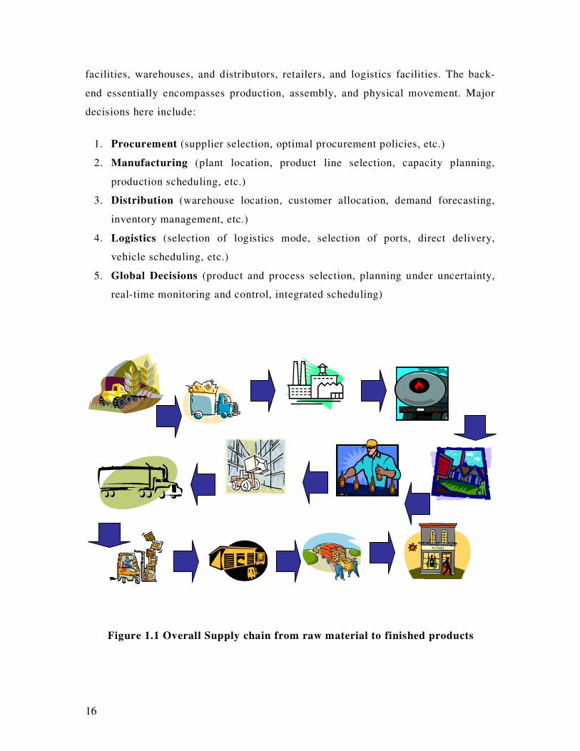
facilities, warehouses, and distributors, retailers, and logistics facilities. The back-
end essentially encompasses production, assembly, and physical movement. Major
decisions here include:
1. Procurement (supplier selection, optimal procurement policies, etc.)
2. Manufacturing (plant location, product line selection, capacity planning,
production scheduling, etc.)
3. Distribution (warehouse location, customer allocation, demand forecasting,
inventory management, etc.)
4. Logistics (selection of logistics mode, selection of ports, direct delivery,
vehicle scheduling, etc.)
5. Global Decisions (product and process selection, planning under uncertainty,
real-time monitoring and control, integrated scheduling)
Figure 1.1 Overall Supply chain from raw material to finished products
17
The second phase is called the front end, where IT and ITEC play a key role. It
involves the processing and use of information to facilitate and optimize back end
operations. Key technologies include:
EDI (for exchange of information across different players in the supply chain),
Electronic payment protocols, Internet auctions (for selecting suppliers, distributors,
demand forecasting) Electronic Business Process Optimization-Logistics,
Continuous tracking of customer orders through the Internet, Internet based shared
services.
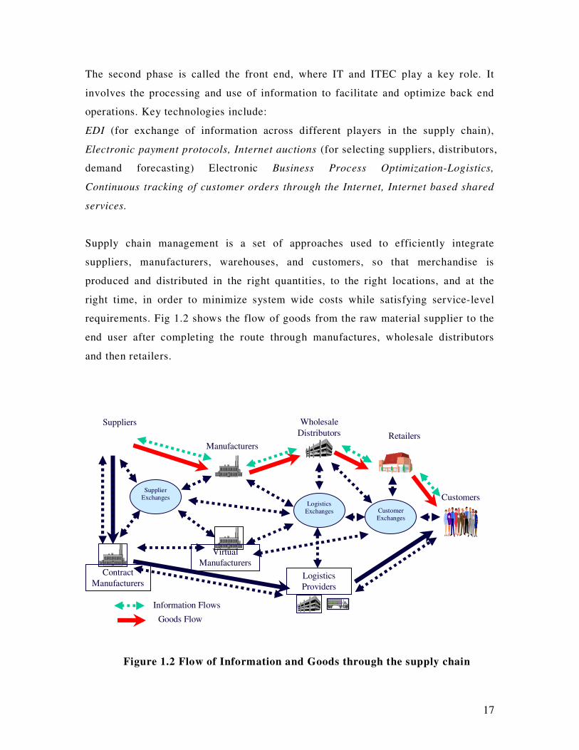
Supply chain management is a set of approaches used to efficiently integrate
suppliers, manufacturers, warehouses, and customers, so that merchandise is
produced and distributed in the right quantities, to the right locations, and at the
right time, in order to minimize system wide costs while satisfying service-level
requirements. Fig 1.2 shows the flow of goods from the raw material supplier to the
end user after completing the route through manufactures, wholesale distributors
and then retailers.
Figure 1.2 Flow of Information and Goods through the supply chain
Manufacturers
Wholesale
Distributors
Suppliers
Customers
Information Flows
Goods Flow
Retailers
Supplier
Exchanges
Customer
Exchanges
Logistics
Exchanges
Contract
Manufacturers Logistics
Providers
Virtual
Manufacturers

18
1.2 Scope of this project
For the scope of this project, we have considered issues in the two most important
sections of SCM: E-Procurement and Logistics Exchanges.
1.2.1 E-Procurement
E-procurement (Electronic Procurement), also known as supply exchange, is the
business-to-business purchase and sale of supplies and services through the Internet,
as well as other information and networking systems, such as electronic data
interchange (EDI) and Enterprise Resource Planning (ERP) - an important part of
many B2B sites. Typically, e-procurement web sites allow qualified and registered
users to look for buyers or sellers of goods and services. Depending on the
approach, buyers or sellers may specify prices or invite bids. Transactions can be
initiated and completed. Ongoing purchases may qualify customers for volume
discounts or special offers.
Companies participating in e-procurement expect to be able to control parts
inventories more effectively, reduce purchasing agent overhead, and improve
manufacturing cycles. E-procurement is expected to be integrated with the trend
toward computerized supply chain management.
E-procurement is the term for electronic procurement or purchasing. It is part of e-
business and is used to designate the optimized, Internet-based acquisition process
of a company. It refers not just to the purchasing process itself, but to electronic
negotiations and the conclusion of contracts with suppliers as well. Because the
purchasing process is simplified by the electronic handling of operative tasks,
strategic tasks can be given a more important role in the process. These new
strategic purchasing tasks include the management of contacts to existing and new
suppliers, as well as the creation of new market structures by actively consolidating
the supply-side.

19
Studies undertaken by [80] indicate that e-procurement contributes benefits to
compliance and spend management initiatives. Some specific advantages of e-
procurement include [81]:
a) Self-Service procurement – enabling self-service at various stages in the
supply chain, such as use of online shopping, and support of plant
maintenance orders.
b) Content management – Ability to import catalog data, or access content from
any source.
c) Centralised contract management – Supports global purchasing, access to
suppliers across geographical entities.
d) Purchasing analytics – Provides extensive reporting capabilities for both
purchasers and managers, resulting in more efficient decisions.
e) Improvement in spend compliance.
Further, the investigation by [80] suggests that e-procurement deployments now
manage more transactions, suppliers, and spend than ever before. Further, it is
delivering measurable improvements in cost, compliance and productivity.
However, supplier enablement, employee adoption, and executive support are the
key challenges.
There are six main types of e-procurement:
o Web-based ERP (Electronic Resource Planning): Creating and approving
purchasing requisitions, placing purchase orders and receiving goods and services by
using a software system based on Internet technology.
o E-MRO (Maintenance, Repair and Operating): The same as web-based ERP
except that the goods and services ordered are non-product related MRO supplies.
o E-sourcing : Identifying new suppliers for a specific category of purchasing
requirements using Internet technology.
o E-tendering : Sending requests for information and prices to suppliers and receiving
the responses of suppliers using Internet technology
20
o E-reverse auctioning : Using Internet technology to buy goods and services from a
number of known or unknown suppliers.
o E-informing : Gathering and distributing purchasing information both to and from
internal and external parties using Internet technology.
Overall, the two main advantages offered by e-procurement include:
a) Furthering the automation of business processes, thereby ensuring that orders
align with those of ERP applications.
b) It is a valuable tool in sourcing new suppliers of goods and services, thus
promoting ‘better value for money’, as competitiveness increases.
1.2.2 Logistics Exchanges
Logistics Exchanges is responsible for various functions, like the selection of Logistics mode,
selection of ports, direct delivery, vehicle scheduling, etc. Advances in communication
technology have made this more efficient. The trend towards wireless technology
increasingly leads us into a new mobile and distributed computing environment.
Wireless technology gives us the capability of accessing information with a nomadic
device, anywhere and at any time.
Although Internet development has been down in recent years, we are still in the
early stages of understanding and uncapping its unlimited potential. The integration
of web services allows our system to be more responsive and automated. MIDAS
(Mobile Intelligent Distributed Application Software) combines these two
technologies to provide an autonomous delivery management system for the
transportation and transport logistics industries.
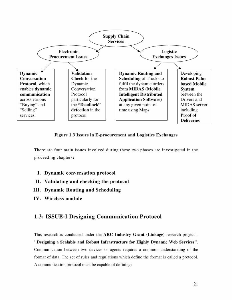
Figure 1.3 shows the architecture of supply chain services and the issues involved in
e-procurement and logistics sections.
21
fs
Figure 1.3 Issues in E-procurement and Logistics Exchanges
There are four main issues involved during these two phases are investigated in the
proceeding chapters:
I. Dynamic conversation protocol
II. Validating and checking the protocol
III. Dynamic Routing and Scheduling
IV. Wireless module
1.3: ISSUE-I Designing Communication Protocol
This research is conducted under the ARC Industry Grant (Linkage) research project -
"Designing a Scalable and Robust Infrastructure for Highly Dynamic Web Services".
Communication between two devices or agents requires a common understanding of the
format of data. The set of rules and regulations which define the format is called a protocol.
A communication protocol must be capable of defining:
Supply Chain
Services
Electronic
Procurement Issues
Logistic
Exchanges Issues
Dynamic
Conversation
Protocol, which
enables dynamic
communication across various
“Buying” and
“Selling”
services.
Validation Check for the
Dynamic
Conversation
Protocol
particularly for
the “Deadlock”
detection in the
protocol
Developing
Robust Palm
based Mobile
System
between the
Drivers and
MIDAS server,
including
Proof of
Deliveries
Dynamic Routing and Scheduling of Trucks to
fulfil the dynamic orders
from MIDAS (Mobile
Intelligent Distributed
Application Software)
at any given point of
time using Maps

22
• Rate of transmission
• Type of transmission (Synchronous or Asynchronous)
• Mode of transmission (Half duplex or full duplex)
• Ability to detect and recover from transmission errors, and for encoding and decoding
data.
1.3.1 Background
Due to the diverse nature of software agents, communication protocols between
agents are not standardized and may offer little interoperability. This often leads to
proprietary interfaces and protocols, but may still provide poor interoperability
between different types of agents. For an information agent operating on the
Internet, its execution environment is not a single controlled framework, but instead,
a large heterogeneous environment where all expected conversations could not be
anticipated. For example, a simple shopping agent may wish to interact with
multiple merchant sites having different protocols to retrieve product information
and purchase goods. An autonomous, long-lived client agent may need to converse
with many sites requiring different conversation protocols for site navigation.
Therefore, operation between information agents on the Internet may be viewed as
the goal.
In these conditions one agent would not care what standard(s) another agent
implemented, provided there was understanding between the agents about what
communication was required. e.g. “I don’t care what your standard is, just tell me
what to speak and I will speak it”. In the Internet commerce environment it is being
used as a replacement for the older technology of EDI. Libraries of XML DTD
documents exist, which are repositories of document definitions that can be used for
sites to exchange data in, typically, an Internet B2B transaction. This provides
“standard” data formats for these transactions.
To provide full operability between information agents on the Internet, we need
agents to not only know the correct data formats to pass, but also the conversation
level protocol involving those messages for any required service. This must also
23
include valid responses, where multiple responses are possible, and the start and end
states of the conversation. Any common aspects between different e-service
providers across an industry may be found at the atomic level of the message, or
document definitions themselves. It is conceivable that industry-wide
interoperability requires a domain of well understood message definitions that can
form any number of interfaces, rather than statically specifying well-known
interfaces, or a work-flow sequence of messages.
This implies that operability between agents, rather than compatibility via any
implemented standard, may be seen as the goal. Agents operating on the Internet
could reasonably be expected to only make use of current Internet standards or
pseudo-standards, in order to provide the most open environment for agents wishing
to interact.
This project proposes a dynamic communication protocol between supply chain
services or their agents. This protocol is implemented using XML and Java, and
provides interoperability across different conversation protocols. An implementation
is tested using applications in a wine selling business domain using three different
protocols. This demonstrates the removal of such protocols from compiled
interfaces, being replaced by one that adapts to changes in messages between
agents.
Communication between entities requires:
• a reliable communication system
• a common understanding of the data being exchanged
• an understanding of the sequence of exchanges, forming a valid communication
protocol
Of these requirements, defining communication protocols may be the most
problematic. While e-services may use well-known transport layer protocols and
implementation languages, communication protocols are application dependant.
Clients wishing to make use of a service must know the message formats and valid
24
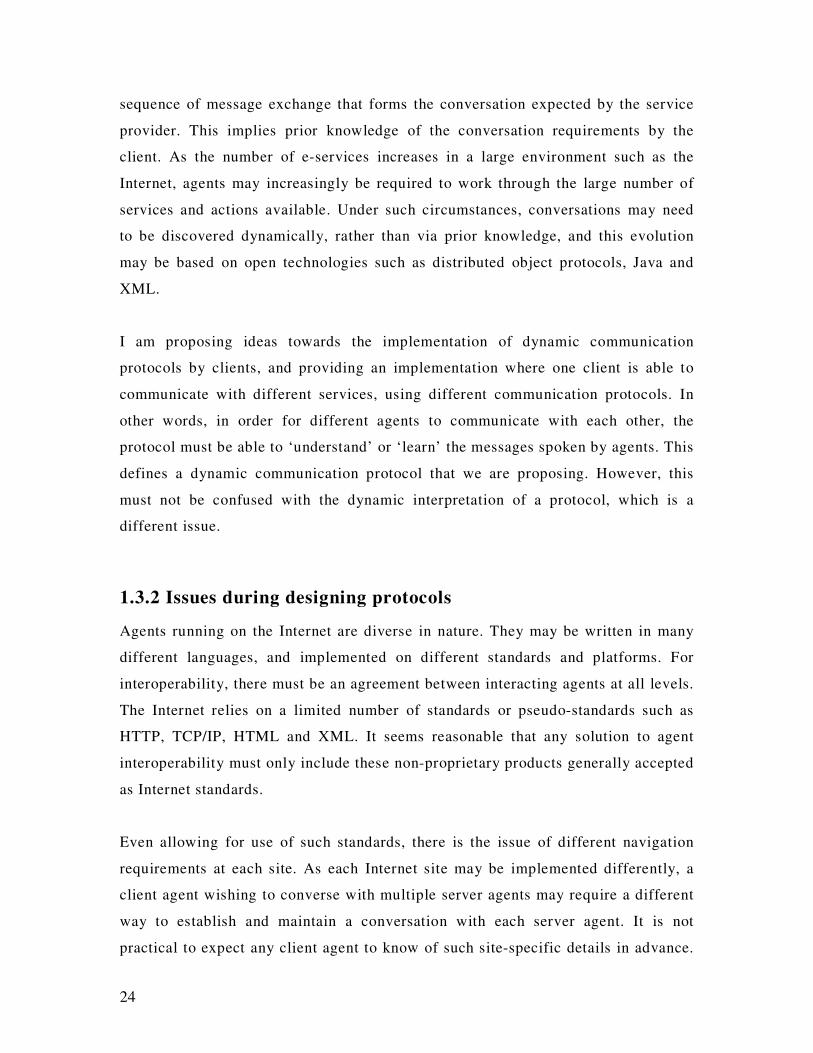
sequence of message exchange that forms the conversation expected by the service
provider. This implies prior knowledge of the conversation requirements by the
client. As the number of e-services increases in a large environment such as the
Internet, agents may increasingly be required to work through the large number of
services and actions available. Under such circumstances, conversations may need
to be discovered dynamically, rather than via prior knowledge, and this evolution
may be based on open technologies such as distributed object protocols, Java and
XML.
I am proposing ideas towards the implementation of dynamic communication
protocols by clients, and providing an implementation where one client is able to
communicate with different services, using different communication protocols. In
other words, in order for different agents to communicate with each other, the
protocol must be able to ‘understand’ or ‘learn’ the messages spoken by agents. This
defines a dynamic communication protocol that we are proposing. However, this
must not be confused with the dynamic interpretation of a protocol, which is a
different issue.
1.3.2 Issues during designing protocols
Agents running on the Internet are diverse in nature. They may be written in many
different languages, and implemented on different standards and platforms. For
interoperability, there must be an agreement between interacting agents at all levels.
The Internet relies on a limited number of standards or pseudo-standards such as
HTTP, TCP/IP, HTML and XML. It seems reasonable that any solution to agent
interoperability must only include these non-proprietary products generally accepted
as Internet standards.
Even allowing for use of such standards, there is the issue of different navigation
requirements at each site. As each Internet site may be implemented differently, a
client agent wishing to converse with multiple server agents may require a different
way to establish and maintain a conversation with each server agent. It is not
practical to expect any client agent to know of such site-specific details in advance.
25
On the Internet, generally, centralized services, or repositories are not available for
discovery. Therefore, the issue remains a site-by-site discovery of such information.
For full interoperability, agents must be able to communicate without
misunderstanding. This implies a certain fundamental level of understanding of
domain-level concepts that may be mapped by individual sites to their internal
representation of relationships of data. In summary, an Internet agent using e-
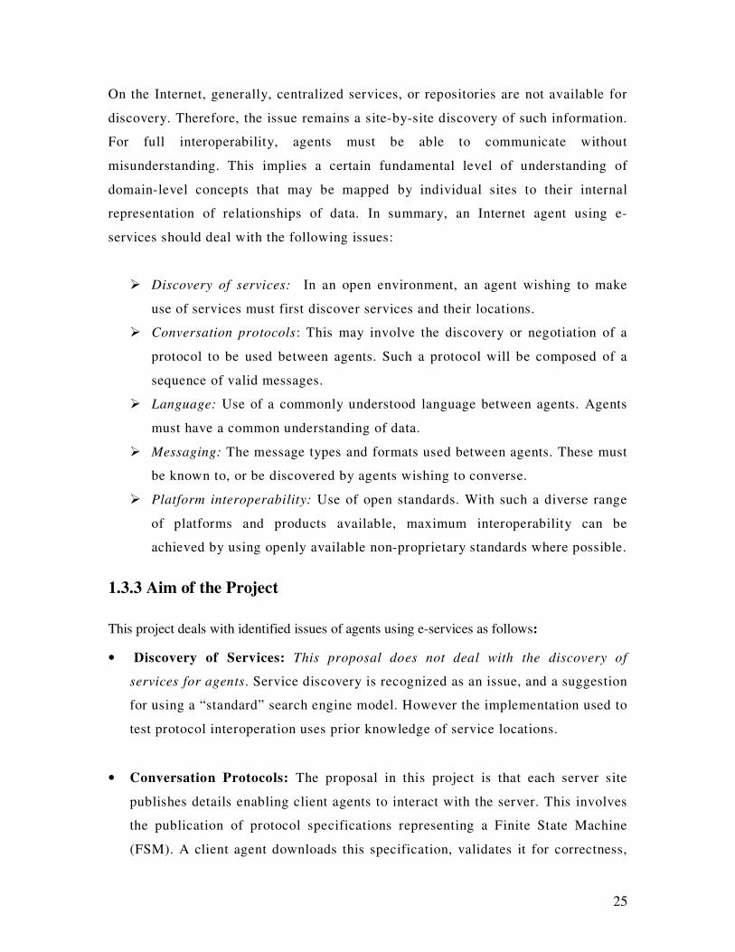
services should deal with the following issues:
� Discovery of services: In an open environment, an agent wishing to make
use of services must first discover services and their locations.
� Conversation protocols: This may involve the discovery or negotiation of a
protocol to be used between agents. Such a protocol will be composed of a
sequence of valid messages.
� Language: Use of a commonly understood language between agents. Agents
must have a common understanding of data.
� Messaging: The message types and formats used between agents. These must
be known to, or be discovered by agents wishing to converse.
� Platform interoperability: Use of open standards. With such a diverse range
of platforms and products available, maximum interoperability can be
achieved by using openly available non-proprietary standards where possible.
1.3.3 Aim of the Project
This project deals with identified issues of agents using e-services as follows:
• Discovery of Services: This proposal does not deal with the discovery of
services for agents. Service discovery is recognized as an issue, and a suggestion
for using a “standard” search engine model. However the implementation used to
test protocol interoperation uses prior knowledge of service locations.
• Conversation Protocols: The proposal in this project is that each server site
publishes details enabling client agents to interact with the server. This involves
the publication of protocol specifications representing a Finite State Machine
(FSM). A client agent downloads this specification, validates it for correctness,
26
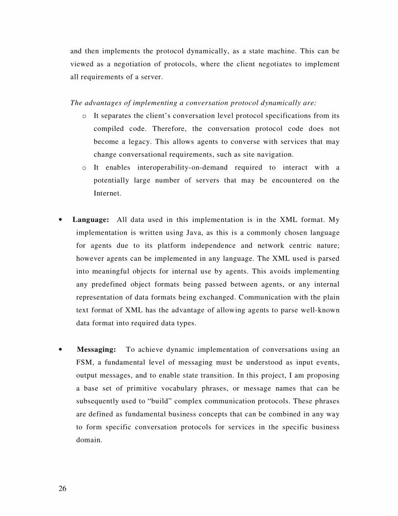
and then implements the protocol dynamically, as a state machine. This can be
viewed as a negotiation of protocols, where the client negotiates to implement
all requirements of a server.
The advantages of implementing a conversation protocol dynamically are:
o It separates the client’s conversation level protocol specifications from its
compiled code. Therefore, the conversation protocol code does not
become a legacy. This allows agents to converse with services that may
change conversational requirements, such as site navigation.
o It enables interoperability-on-demand required to interact with a
potentially large number of servers that may be encountered on the
Internet.
• Language: All data used in this implementation is in the XML format. My
implementation is written using Java, as this is a commonly chosen language
for agents due to its platform independence and network centric nature;
however agents can be implemented in any language. The XML used is parsed
into meaningful objects for internal use by agents. This avoids implementing
any predefined object formats being passed between agents, or any internal
representation of data formats being exchanged. Communication with the plain
text format of XML has the advantage of allowing agents to parse well-known
data format into required data types.
• Messaging: To achieve dynamic implementation of conversations using an
FSM, a fundamental level of messaging must be understood as input events,
output messages, and to enable state transition. In this project, I am proposing
a base set of primitive vocabulary phrases, or message names that can be
subsequently used to “build” complex communication protocols. These phrases
are defined as fundamental business concepts that can be combined in any way
to form specific conversation protocols for services in the specific business
domain.

27
An advantage of providing these message definitions at a fundamental business
level, rather than at an implementation level, is that it allows any
implementation, provided the fundamental business concept is adhered to. This
promotes interoperability as there will be a common understanding of message
types. The limitations are that there may need to be some mapping from these
ontological business concepts to internal representations, and that such
mapping may require a form of similarity matching involved in this mapping.
• Platform Interoperability. Implementation in this project has used only
Internet standards or pseudo-standards to promote independence of platform.
Commonly used communication protocols include TCP for the transport layer
and HTTP for the application layer. With the use of XML for data content, this
has the advantage of allowing any higher level implementation, provided these
standards are used. For example, if standard HTTP client/server requests are
used, any server-side implementation supporting these requests (eg Java
Servlets, CGI, ASP etc) can be used. This is an advantage over requiring any
higher level application protocol (such as SOAP [12], ATP [3], and SCMP
[13]) as these are either proprietary, or still emerging as accepted standards.
1.4 ISSUE II: Protocol Correctness
This research is conducted under the ARC Industry Grant (Linkage) research project -
"Designing a Scalable and Robust Infrastructure for Highly Dynamic Web Services".
All communication, either in the same environment, or in an inter-agent environment,
depends on the protocols used. Protocol design is not sufficient; it is important that they work
well. A lot of techniques are in use, which make it possible to validate the protocol for
correctness. This chapter presents our proposed model of Communicating Complex State
Machines (CCSMs) and defines the concepts related to this model. This chapter also
illustrates the algorithms of our proposed protocol validation technique for deadlock
detection in CCSMs. We are considering the Finite State Machine for the purpose of protocol
validation, so protocol behaviour depends on the behaviour and functioning of the FSM,
28
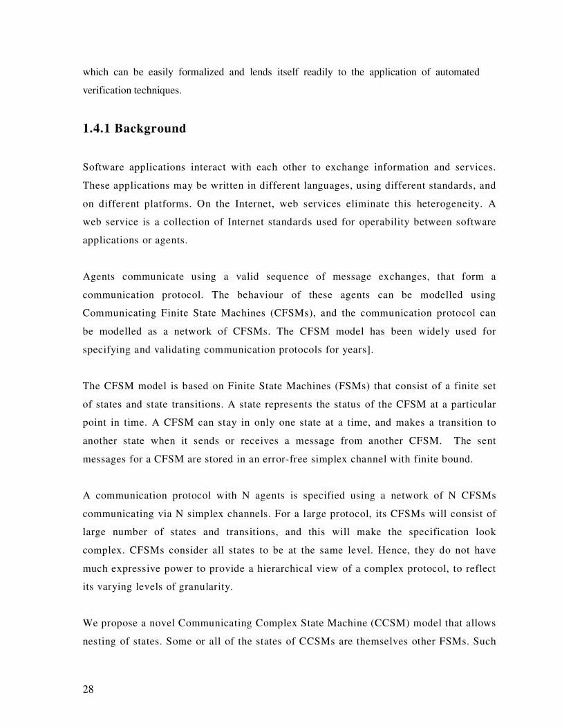
which can be easily formalized and lends itself readily to the application of automated
verification techniques.
1.4.1 Background
Software applications interact with each other to exchange information and services.
These applications may be written in different languages, using different standards, and
on different platforms. On the Internet, web services eliminate this heterogeneity. A
web service is a collection of Internet standards used for operability between software
applications or agents.
Agents communicate using a valid sequence of message exchanges, that form a
communication protocol. The behaviour of these agents can be modelled using
Communicating Finite State Machines (CFSMs), and the communication protocol can
be modelled as a network of CFSMs. The CFSM model has been widely used for
specifying and validating communication protocols for years].
The CFSM model is based on Finite State Machines (FSMs) that consist of a finite set
of states and state transitions. A state represents the status of the CFSM at a particular
point in time. A CFSM can stay in only one state at a time, and makes a transition to
another state when it sends or receives a message from another CFSM. The sent
messages for a CFSM are stored in an error-free simplex channel with finite bound.
A communication protocol with N agents is specified using a network of N CFSMs
communicating via N simplex channels. For a large protocol, its CFSMs will consist of
large number of states and transitions, and this will make the specification look
complex. CFSMs consider all states to be at the same level. Hence, they do not have
much expressive power to provide a hierarchical view of a complex protocol, to reflect
its varying levels of granularity.
We propose a novel Communicating Complex State Machine (CCSM) model that allows
nesting of states. Some or all of the states of CCSMs are themselves other FSMs. Such
29
states are called complex states while others are called simple states. The internal FSM
of a complex state could also be a Complex State Machine (CSM), thereby allowing
multi-level complexity in the protocol. The aim of embedding states within states is to
address the above shortcomings of CFSMs. CCSMs support hierarchy, modularity,
component reuse and a concise presentation of large and complex protocols.
A communication protocol needs to be validated against the existence of logical errors
to provide quality assurance of a communication system. This validation can be done
either during the specification phase before the protocol is executed, or during the
testing phase after the protocol has been executed. To avoid unnecessary
implementation, validation should be done in the protocol specification stage. A correct
protocol satisfies a certain desired set of properties. The absence of deadlock, liveness,
unspecified reception, non-executable transitions and buffer-overflow are examples of
such properties.
Protocol validation can be achieved either by exhaustive exploration or by partial
exploration of the protocol state space. In the former technique, a protocol is validated
by generating all its reachable states and checking each of them for errors. Such a
technique can generally detect all kinds of protocol design errors however it requires
large time and space complexities. Reachability analysis, structural analysis and N-tree
validation are exhaustive exploration techniques. In the latter technique, only partial
state space of the protocol is explored for its validation. Such a technique attempts to
reduce the computational complexity of the validation task; however it generally
validates the protocol against some errors only.
Maximal progress state exploration, reverse reachability analysis, random walk and
simultaneous reachability analysis are partial exploration techniques.
We propose a protocol validation technique that partially explores the protocol state
space for deadlock detection in a network of CCSMs. A deadlock occurs in a protocol
when all the CCSMs are unable to make a move from their current states. This happens
when the current states of all the CCSMs, with only a ‘receiving’ transitions departing
from them, but all the channels are empty. Our proposed algorithm identifies the
30
possible deadlock states in the protocol and then backtracks via their past transitions to
check if they can really cause deadlocks.
Only the states that send no messages and have no choice but to wait for receiving
messages can cause deadlocks. Such states are identified as possible deadlock states.
Backtracking is done to check whether the messages expected by such states were ever
sent by the other CCSMs. If yes, then such states will eventually receive the message
and move to another state. If no, such a state will wait forever and cause a deadlock.
Such states are reported as the deadlock states by our algorithm.
The following section puts light on some of the models for protocol representation.
We describe the CFSM model in detail, which forms the basis of our proposed
model.
Modelling Protocols
This section provides a brief introduction to some of the most common models for
protocol representation. The most general model represents communication protocols as
parallel programs. This model can specify all protocols and most of the properties.
However, one limitation is that the protocol cannot be validated against all kinds of
protocol design errors.
As the name suggests, a CCSM allows uni-directional communication across un-
bounded FIFO (First-In-First-Out) channels between machines in a network. They are
useful in the modelling, verification and synthesis of communication protocols and
distributed systems [79]. A Petri net (PN) is another model used for protocol
representation. It offers a means of modelling complex processes and is generally
categorised into low or high-level PNs. Coloured Petri-nets (CP-nets) are a variation on
PNs, and allow modelling of a system as a combination of a PN and a programming
language. A number of CP-nets combined together in a particular format form a
hierarchical CP-net, which allows the construction of large models.
31
Both CCSMs and CP-nets can be used to model communication protocols. The latter
generally applies to modelling systems in which the key characteristic is concurrency.
The former supports one-to-many synchronous communications with value passing,
hence making it ideal for modelling communication protocols. Although both
techniques offer similar characteristics, in CP-nets, protocols can be analysed more
easily, but some properties cannot be determined. It is a less general model than
parallel programs, and has less expressive power. Further, CCSMs offer a simple
approach to the investigation we are undertaking, whereas hierarchical CP-nets are
better suited to more complex modelling.
The CFSM model represents the protocol including all communicating processes and
interconnecting channels. In this model, a protocol allowing an arbitrary number of
messages in transit cannot be represented. This model makes the analysis of the
protocols easy and complete, as all the properties can be determined. It implies that all
the design errors can be detected by exhaustive exploration techniques. This fact has
led us to choose this model as the base of our proposed model.
The following section introduces the concepts of the CFSM model and shows how it
represents the behaviour of agents and the communication protocols.
CFSM Model
The CFSM model is based on the Finite State Machines (FSMs) that consist of a finite
set of states and state transitions. A state represents the status of the communicating
entity at a particular point in time. A communicating entity can be in only one state at a
time. A CFSM makes a transition to another state when it sends or receives a message
from another CFSM. A CFSM can formally be represented as an FSM ( )TASqC f ,,,, .
where:
• C is the set of states of the communicating entity.
• q is the initial state where Cq ∈ .
• fS is the set of final states where CS f ⊂ .
32
• A is the communicating alphabet which represents the set of valid message
types.
• T is a map of state transitions ( )CAC ×× such that the FSM will move from the
current state to another state when applied with a transition.
A transition relation can be represented by a quadruple as ( )emth ,,, where:
• Ch ∈ is head of the transition i.e. the state where the transition originated.
• Ct ∈ is tail of the transition i.e. the state where the transition terminated.
• Am ∈ is the message that is sent or received.
• e is the ‘sending’ or ‘receiving’ event.
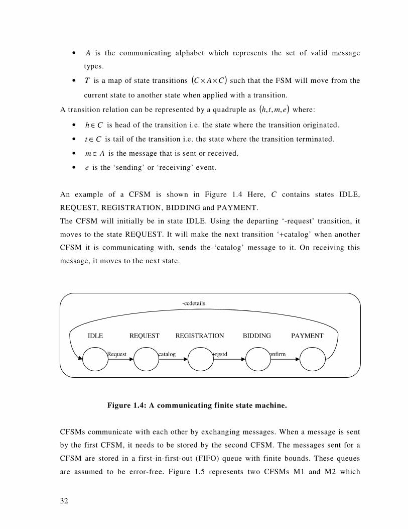
An example of a CFSM is shown in Figure 1.4 Here, C contains states IDLE,
REQUEST, REGISTRATION, BIDDING and PAYMENT.
The CFSM will initially be in state IDLE. Using the departing ‘-request’ transition, it
moves to the state REQUEST. It will make the next transition ‘+catalog’ when another
CFSM it is communicating with, sends the ‘catalog’ message to it. On receiving this
message, it moves to the next state.
Figure 1.4: A communicating finite state machine.
CFSMs communicate with each other by exchanging messages. When a message is sent
by the first CFSM, it needs to be stored by the second CFSM. The messages sent for a
CFSM are stored in a first-in-first-out (FIFO) queue with finite bounds. These queues
are assumed to be error-free. Figure 1.5 represents two CFSMs M1 and M2 which
-ccdetails
-Request +catalog +rgstd -confirm
IDLE REQUEST REGISTRATION BIDDING PAYMENT
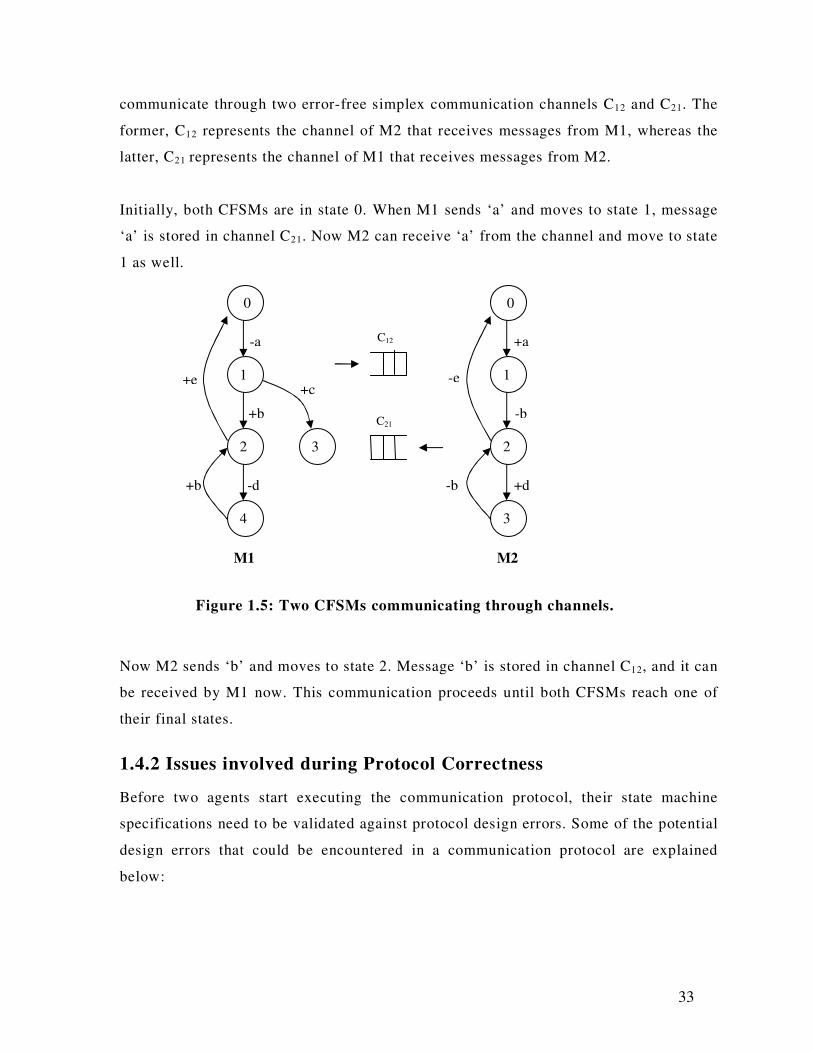
33
communicate through two error-free simplex communication channels C12 and C21. The
former, C12 represents the channel of M2 that receives messages from M1, whereas the
latter, C21 represents the channel of M1 that receives messages from M2.
Initially, both CFSMs are in state 0. When M1 sends ‘a’ and moves to state 1, message
‘a’ is stored in channel C21. Now M2 can receive ‘a’ from the channel and move to state
1 as well.
Figure 1.5: Two CFSMs communicating through channels.
Now M2 sends ‘b’ and moves to state 2. Message ‘b’ is stored in channel C12, and it can
be received by M1 now. This communication proceeds until both CFSMs reach one of
their final states.
1.4.2 Issues involved during Protocol Correctness
Before two agents start executing the communication protocol, their state machine
specifications need to be validated against protocol design errors. Some of the potential
design errors that could be encountered in a communication protocol are explained
below:
0
4
2
1
3
0
1
2
3
-a
+c
-b +d
-b
+a
-d
+b
+e
M1 M2
+b
-e
C12
C21
34
� Deadlock: A deadlock error occurs in a protocol when all entities are unable to
make a move from their current states. This happens when the current states of
all entities only have ‘receiving’ transitions departing from them, but all the
channels are empty. Thus, no state can receive a message and no transitions are
possible from the current state of all entities.
� Unspecified Reception: An unspecified reception error occurs when a state
encounters an input message that it does not have a ‘receiving’ transition for. In
a protocol, when a ‘sending’ transition does not have a corresponding
‘receiving’ transition in the receiving state machine, the current global state is
said to be an unspecified reception global state.
� Buffer Overflow Error: A buffer overflow error occurs when a channel is
already full and a message is sent to it. This only happens when the entities of a
protocol have finite-capacity (bounded) channels.
� Livelock: A livelock error occurs when processes continually exchange the same
messages and do not make any progress towards protocol completion. This
usually happens due to infinite loops in the specification.
� Non-Executable Transitions: Transitions that cannot occur under normal
operating conditions are called non-executable transitions. A non-executable
transition is equivalent to a dead code in a computer program.
For a communication system represented using the CFSM model, if complexity of the
communication protocol increases, the specification gets larger, resulting in a high
number of states. The CFSMs consider all states to be at the same level. Hence, CFSMs
do not have much expressive power to provide a hierarchical view of a complex
protocol to reflect its varying levels of granularity. Also, when a certain sequence of
states and transitions is significant and used again in the state machine, the CFSM
model will just repeat the sequence. This indicates the lack of modularity and
component reuse in this model.
35
We aim to propose a state machine model that will add more expressive power to
CFSMs in order to resolve the above stated issues.
The communication protocol needs to be validated against the existence of logical
errors to provide quality assurance of a communication system. The protocol design
errors, if not detected, could lead to do some harm to the agents executing them.
Exhaustive exploration techniques like reachability analysis require large computational
complexity, and so may not be practical for the validation of a large protocol. Partial
exploration techniques like reverse reachability analysis attempt to reduce
computational complexities while detecting a specific kind of design error. Reverse
reachability analysis for deadlock detection does not divide the validation task into
independent subtasks for each communicating entity. We aim to propose a partial
exploration technique to validate the protocols against deadlocks and provide improved
complexity compared to reachability analysis. We also aim to divide the validation task
into subtasks to further improve efficiency over reverse reachability analysis.
Distributed systems offer an abundance of applications in the current world. With its
various properties, including liveness (progress occurs in a system), boundedness
(occurring in a finite state space) and termination (when every process is idle, and there
is no message in transit) come various problems as well. Communication protocols play
an important role in distributed systems, as the mentioned properties relate to them.
Deadlocks have been chosen in this investigation instead of other properties mentioned
above (liveness, boundedness or termination) because of the amount of interest in this
area. Deadlock detection is a very crucial issue in the operation of distributed systems.
Further, it is also related to other properties and/or problems in distributed systems. The
most common one is that deadlock avoidance algorithms guarantee liveness. Moreover,
according to [77], deadlock detection, which is related to termination detection, is of
fundamental importance.
36
1.4.3 Aim of the Project
We propose a novel Communicating Complex State Machine (CCSM) model that allows
nesting of states. Some or all of the states of CCSMs are themselves other FSMs. Such
states are called complex states, while others are called simple states. The internal FSM
of a complex state could also be a Complex State Machine (CSM), thereby allowing
multi-level complexity in the protocol. The CCSM representation shows the following
advantages over CFSMs:
• It supports hierarchical decomposition of states that allows the state machines to
be viewed at varying levels of granularity.
• It introduces modularity and component reuse by allowing a significant sequence
of states and transitions to be replaced by a complex state.
• It presents a compact and higher level service behaviour of the entities in a
protocol.
• For strict CCSMs, the protocol validation of complex states can be performed in
parallel.
For the purpose of protocol validation, we propose a deadlock detection technique
that partially explores the protocol state space to identify the following types of
deadlocks in CCSMs:
I. Simple deadlocks: Deadlocks occurring when all CCSMs are in one of their simple
states.
II. Complex deadlocks: Deadlocks occurring when all CCSMs are in one of their
complex states.
III. Hybrid deadlocks: Deadlocks occurring when some of the CCSMs are in simple
states while the rest are in complex states.
Our proposed protocol validation technique is implemented and tested on various
protocols and communication systems. The comparison between reachability analysis
and reverse reachability analysis shows the following results:
37
• Like the compared techniques, our validation technique detects both the presence
and absence of deadlock errors in protocols.
• Our validation technique will perform better than reachability analysis in most
cases.
• Our algorithm will perform at least equally well as reverse reachability analysis
in most cases.
• Unlike the compared techniques, our technique divides the validation task into
independent subtasks which can be executed in parallel, to further reduce time
complexity.
1.5 ISSUE III: Routing and Scheduling
This research is conducted under the ARC Industry Grant (Linkage) research project -
"Developing a Mobile Integrated Distributed Broker for On-Line Transport Industry
Applications". In networking terms, routing is a key feature of the Internet because it
enables messages to pass from one computer to another and eventually reach the target
machine. Part of this process involves analysing a routing table to determine the best path.
Routing is a complex process of determining which links and nodes will move the packet to
its final destination. This process is the same in case of vehicle routing; the only difference is
that nodes are considered vehicles, and destination machines are customers. Just as in the
previous case, there is a need to find out the best possible path to serve the customer.
1.5.1 Background
Efficient route scheduling can affect client/customer satisfaction and cut operating
costs in the transport industry. Dynamic scheduling has simplified transport
logistics such as courier services, by providing technology-enhanced, real-time
communication. Service requests from the same area should be served once rather
than multiple times, facilitating a huge saving in travel distance and time. However,
the time constraints of individual delivery in courier services increases through the
38
complexity of route scheduling in terms of providing good services and minimizing
operating costs.
As a contribution to Mobile Intelligent Distributed Application Software (MIDAS),
the intention of this project is to develop an autonomous route scheduling system,
which will enable smoother running of transportation logistics with efficient
operation costs, by combining wireless and Internet technology. This system can
receive orders and requests from mobile devices (Palm) and the Internet, which can
be scheduled and forwarded to the drivers automatically. Autonomous route
scheduling will be the foremost concern of this project, which includes static and
dynamic scheduling to produce an optimal route. Static scheduling is used to deal
with non-emergency orders that can be scheduled overnight, resulting in a better
solution with sufficient computation time. Dynamic scheduling can also be used to
deal with emergency orders that require real-time scheduling within limited time
constraints. This system will also enhance the operator’s functionalities, such as the
facility of driver tracking and locating the nearest vehicle with digital maps.
• Wireless Technology
In recent years, the use of wireless technologies has grown rapidly under research
topics. In the near future, its capacity will evolve significantly under the 3rd-
Generation (3G) network infrastructure for the mobile network. Due to these
advances, the varieties of devices and applications have been gradually pushed into
the commercial market to amalgamate new wireless technology, such as Tablet PC
and Personal Digital Assistants (PDA) with the mobile phone. Richer data formats,
such as personal images, can now be sent across the mobile network. In the not-too-
distant future, we will be able to have face-to-face conversations on a mobile phone
using broad bandwidth. The benefit of new wireless technology has accommodated
mobile computing; an extended distributed computing, an extended distributed
computing concept.
Broad bandwidth can provide an inclusive environment for us to communicate with
remote host systems anywhere, at anytime, with the ability to send more data
39
between mobile devices. In light of these advances, the generic public network and
various devices, can be utilized by the transport industry to provide an efficient
service without a huge investment in a customized approach.
• Internet
Due to the evolution of the Internet, the global network provides an effective
information access channel without the limitation of physical distance. The link
between different systems allows for information sharing. In terms of business, the
Internet acts as an open market, facilitating more business transactions globally than
ever before. Moreover, the Internet allows e-commerce to be more automated.
Compared with the “bricks and mortar” approach, ordering information over the
Internet can be easily saved to the database directly without re-entering. Customers
can receive a direct response in getting any item from an inventory without the
inconvenience that is often created by human delay. All these processes can be done
in just a few seconds through an Internet enabled device. The Internet has
dramatically improved and transformed how business is done. It facilitates
sophisticated and efficient business transactions around the world. The transport
industry, for instance, depends on effective services, such as a seamless
communication channel in medical couriering. Therefore, integration of the Internet
can provide a direct and efficient service for transport company customers without
any operation delays.
• MIDAS
The aim of MIDAS is to provide an autonomous delivery management system for
the transport industry, from client orders to proof of delivery. To accomplish this,
MIDAS utilizes different technologies, including Global Positioning System (GPS),
wireless technology (Short Message Service (SMS)/Wireless Application Protocol
(WAP)) and the Internet. One of the main tasks of MIDAS is route planning. This
will provide both static and dynamic scheduling using wireless communication

40
channels to keep drivers up-to-date with information in real time when they are off-
site. MIDAS also benefits clients of the transport companies, whose orders can be
easily placed and traced anywhere at any time.
MIDAS resides in three components: mobile devices, an Internet server and the
MIDAS server. These will provide different capabilities that are presently lacking in
the existing software of transport companies. In any case, coexistence between
MIDAS with the existing software of these transport companies can also be done
without dramatic integration changes. Figure 1.6 shows an overview of the MIDAS
architecture and its sub-components.
Figure 1.6 MIDAS Architecture.
Figure 1.6 Architecture of MIDAS
1.5.2 Issues involved during Routing and Scheduling
The scheduling requirements of this project can be viewed as a combination of
vehicle navigation and scheduling. These require two searches - local and global,
during scheduling. First, a local path between two points is required in a local
search. Then, an order of multiple service locations has to be arranged, as global, to
Existing software
Customer Driver Salesperson
Storage
Ordering
Scheduling
Mapping
Tracking and
Statistic
Routing
Operator
Internet WAP Palm
Database Management System
SMS
41
match the time constraint of services. Due to the need to manage the complexity of
navigation and scheduling in the project, we need to consider the following points.
� Vehicles or customers can appear at any point on the map. They may not
necessarily be next to or on a road line. Moreover, the system is not scalable
– it cannot examine every single road to determine the starting point for the
vehicle. Thus, we need to figure out how to find the nearest entry point on
the road network in an efficient route, and establish a connection between the
two points.
� Branches appear at intersections between two roads; two different paths
can reach the same destination. It is also not scalable to examine every
branch to obtain the best result. Therefore, recognizing the shortest path
between source and destination requires an efficient algorithm.
� An optimal route of scheduling requires swapping between different
locations to fit into service time constraints. In addition, the larger the
numbers of locations being served, the better the solution. The trade-off
between fast computation performance and a better solution has to be kept in
balance. In order to balance these factors, different algorithms are required
for emergency non-emergency services.
� Two communication channels have to be aligned and achieved in this
project: a communication channel between applications and one between the
system and drivers. Between applications, a standard communication
protocol is required, must be adaptable to both Palm devices and an Internet
server. In the driver communication, a simple messaging system is required.
� The fundamental elements of achieving route scheduling are location and
distance information. Therefore, map data is an essential component to
generate a realistic scheduling system. An Australian map is vital for this
project.
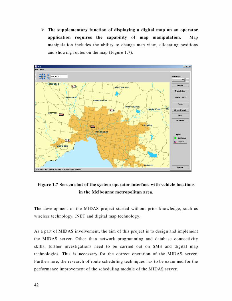
42
� The supplementary function of displaying a digital map on an operator
application requires the capability of map manipulation. Map
manipulation includes the ability to change map view, allocating positions
and showing routes on the map (Figure 1.7).
Figure 1.7 Screen shot of the system operator interface with vehicle locations
in the Melbourne metropolitan area.
The development of the MIDAS project started without prior knowledge, such as
wireless technology, .NET and digital map technology.
As a part of MIDAS involvement, the aim of this project is to design and implement
the MIDAS server. Other than network programming and database connectivity
skills, further investigations need to be carried out on SMS and digital map
technologies. This is necessary for the correct operation of the MIDAS server.
Furthermore, the research of route scheduling techniques has to be examined for the
performance improvement of the scheduling module of the MIDAS server.

43
I.5.3 Aim of the Project
The twin goals of this project are designing and implementing the server-side
components of MIDAS. This will supply a route scheduling solution and
integrate maps to provide an efficient delivery solution in real-time for the
transport industry. The scope of this project will enable handling of the following
scenarios.
• When the MIDAS server receives a valid order from the Internet/PDA, it has to
determine what day the order needs to be delivered by. If an order can be
fulfilled on the next day, it will be stored in the database, ready to be retrieved
for scheduling during the night. Afterwards, the scheduled manifests can be
distributed to the drivers in the morning with a supplementary route map.
Otherwise, the MIDAS system determines and then requests the most
appropriate vehicle that can fulfil the order within the given time frame. The
driver of the vehicle is then contacted through Short Messaging Service (SMS)
to accept the new order and new route. Conversely, a customer must be
immediately informed about an unresolved order through the autonomous
system.
• From the system operator’s perspective, the operator can track all the current
locations of vehicles on the digital map. Furthermore, the closest vehicle can
be indicated with a given location. It is also able to show a route on the map
for different drivers.
SMS messaging originally applies to cellular phones. However, it is increasingly
becoming common to send an SMS message from the Internet to a cellular phone. It
can be seen as a replacement of the primitive pager system, but with more
applications. It can apply to job despatch with instant messaging in the mobile
environment. Using current technology, it is not a problem for software applications
to access the SMS network. However, it is the ease of its usage for customized
applications that still remains in question. In the initial approach, a sophisticated
SMS manager development kit was found for SMS access by using a low level of
communication protocol, which is developed in C. This increases the development

44
practice of SMS functionality of the MIDAS server. Later on, the investigation
process found a much simpler approach, which is supplied by an intermediate
service provider using Java application-programming interface (API). At the same
time, we also proposed a simulation approach by sending SMS messages
through an Internet browser simulation as an alternative for the solution.
The learning of map API is the most basic requirement for digital map
manipulation. The ability of rendering different localities is often used for tracking
and labelling on the map. Moreover, an understanding of the map data structure
enhances the feasibility of mapping development. This project is an Australia based
application, but there is not much sample map data that covers the entire Australian
road network and localities.
In route scheduling development, there are not many papers that provide a complete
and realistic solution for this project. Most of them focus on vehicle routing
algorithms, without specifying the actual distances obtained in real time. Therefore,
additional steps are required.
Firstly, a new data structure must be constructed for routing. Although the map
API can access the map data without any trouble, it is only suitable for map
rendering. Hence, a low level of map data access mechanism is reproduced to
provide a new data type for the new data structure.
Secondly, there is an additional dynamic search that needs to be developed for
routing, according to the realistic map data. Besides the new data structure, the
start of the search also requires the closest point search for entry to the road
network, and then executes the path search. Afterwards, the second dynamic search
can be applied for scheduling with time and load constraints, by using the vehicle
routing algorithm.
45
1.6 ISSUE IV: Wireless Module
This research is conducted under the ARC Industry Grant (Linkage) research project -
"Developing a Mobile Integrated Distributed Broker for On-Line Transport Industry
Applications". In the field of communications, wireless is currently performing a key role.
With advances in technology, the communication field coverage with wireless has also
increased. Wireless technology is based on the IEEE (Institute of Electronics and Electrical
Engineers) 802.11 standard, which is one of the many standards of the IEEE 802 LAN/WAN
standards. The term wireless technology is generally used for mobile IT equipment. It
encompasses cellular telephones, Personal Digital Assistance (PDA’s), and wireless
networking. In our, project we are using wireless because the communication area is quite
large and its main purpose is to send SMS, track the position of trucks, provide the best
possible route, and send information back to drivers.
1.6.1 Background
The improvement in mobile technology and wireless communication has enabled a
new software system to be developed, which enables the transport industry to
perform electronic business transactions, such as sending orders electronically,
checking invoices and automatic proof of delivery. Additionally, it can improve
their services to customers without the limitations outlined above.
A working version of the system has been presented to the industry and research
centre representatives. Useful and encouraging feedbacks were obtained during the
presentations and it is recognized that this system can change the way business
transactions are done, and can introduce a more competitive market. The
performance of the system is very good, taking less than thirty seconds to complete
a business transaction at a cost of less than fifty cents.
46
The goal of the project is to develop a sophisticated software system to deal
with electronic business transactions. It consists of four major components,
namely:
- Handheld Application
- Handheld Conduit
- Desktop Application
- WAP Application
The handheld application will be used by customers and/or marketing staff to place
and/or take orders for transport companies. Upon completing the electronic order
form on the handheld devices, the orders will be sent directly to the target company.
It communicates the order details with the receiving server using a wireless network
connection such as GSM or GPRS. Apart from this capability, customers can also
check their order invoices through the handheld devices, which could help them in
decision-making. This application is targeted to run on Palm Powered™ handheld
devices.
The Handheld conduit is an application module that is attached to the Palm’s
HotSync Manager to perform data synchronization between the handheld device and
either a local or remote desktop computer. Data Synchronization occurs when
information on either desktop computer or handheld device gets updated to ensure
that information is up to date. The HotSync Manager receives the synchronization
request and manages the synchronization process, but it is the conduit application
module that actually performs data synchronization based on the information
provided by the manager.
The synchronization process can be used as a means to backup the handheld data or
transfer data to the handheld device. The data communication and the
communication protocols used between handheld device and conduit application
module are defined by the HotSync Manager.

47
The desktop application is a component that operates in addition to the handheld
application, which should be part of the handheld conduit. It can be used to view
handheld data at a desktop computer.
The WAP application can be used by drivers to communicate with the transport
company while they are on the move. By using this application, drivers can obtain
more information about orders by sending a request to the server that contains the
order booking number. Drivers can also update information about orders to the
transport company such as the status.
Figure 1.8 provides an overview of the overall software system, which system can be divided
into three different layers. The first layer is the system client, which consists of the handheld
application, handheld conduit, desktop application and WAP application, and where users
interact with the system.
Figure 1.8 Overview of the software
The next layer is the web portal. It is responsible for managing the transfer of data between
different devices and multiple MIDAS servers. The web portal will also keep track of
business transactions that have been performed for other purposes such as financial auditing.
…
Handheld
Application
Handheld
Conduit
Desktop
Application
GSM /
GPRS
Web Portal
Midas
Server 1 WAP Module
INTERNET
Midas
Server 2
Midas
Server n

48
The last layer is the MIDAS server that resides on different transport companies. This layer
works in conjunction with the existing system, and manages orders in terms of automatic
manifest scheduling and finding the optimum route.
1.6.2 Issues related to Wireless Module
The software system uses several different technologies, each offering its own
advantages and limitations. Some technologies used, include Palm Powered™
handheld devices, wireless communication network (GSM/GPRS), XML document
data description, mobile phone, and WAP protocol.
Palm Powered™ handheld devices have been selected as a platform on which the
handheld application will be developed. Its selection is based on the device
popularity among other handheld devices in the market, and its ease of use. It is
important for the handheld application to have wireless communication with the
server. This can be achieved using either the GPRS or GSM network. Mobile phones
with WAP capabilities are intended for drivers to communicate with the main office.
For data communication to occur between the client and server, a communication
protocol has been derived to accommodate message exchange. The message format
that is used to communicate information contains XML data documents that
represent the information being communicated. XML is used because of its generic
nature, making it easier to achieve interoperability, and for future expansion.
Another protocol is required to handle a possible processing failure at the server.
This protocol is important since the client needs to know if the transaction is
successful or not. A very important part of the system is the interaction between
users (Customers / Marketing staffs / Drivers) and the server, which is achieved by
using a wireless connection and its related technologies However, there are
problems and limitations that need to be considered since they could affect system
performance. Wireless communication has grown rapidly and many approaches have
been proposed but there are still problems that occur, such as:
49
� Frequent disconnection
It is in the nature of wireless networks for disconnections to occur more easily
and frequently. A connection could be broken when the signal is blocked or
when there is no wireless network coverage in the area, known as black spots.
� Bandwidth
Since the wireless connectivity that is available in Australia is obtained through
mobile phones, the capacity of data transfer depends on the capacity of mobile
phones. A significant improvement in wireless networks is the ability to support
higher bandwidths. Previously, in GSM, (the most common network for mobile
phones) supported only up to 9.6 kbps of data transfer. Currently, wireless
connections can support up to 56 kbps for both GSM and GPRS networks. Even
though the connection bandwidth has improved, optimum performance cannot be
guaranteed because interference is a major drawback in wireless networks.
Therefore, it is necessary to transmit as little data as possible in a short period of
time.
� Security
Transferring information via a wireless network is not the same as a wired network. It
is prone to security breaches since anyone can easily get connected to a wireless
network and hack into it. Data security is very important in electronic business
transactions to protect against malicious attacks.
50
Handheld devices, used as a media to collect and transmit information to the
server via a wireless network connection, also have limitations, despite
improvements in recent years. These limitations include:
� User Interface
The standard screen size of a handheld device is quite small - 160x160 pixels.
This limitation needs to be taken into consideration when developing the user
interface. Information displayed should be as compact as possible, and the
interactions between users and the device should be kept minimal. The types of
user interface components are very limited in handheld devices, and component
behaviour is determined by the application developer.
� Storage capacity
The standard storage of Palm Powered™ handheld devices is 8Mb of RAM,
which means that it would be hard to store large applications or data on the
device. Because of limited storage, the handheld device is designed based on the
concept of managing memory as a chunk, with the largest being 32 kilobytes.
This design would restrict the way in which large applications and data are
stored.
� Energy resource
Handheld devices are usually powered by a rechargeable battery and the lifetime
of the device depends on the battery lifetime. Even when devices are not in use,
they still consume battery power to preserve the data stored in memory.
� Processing power
Because of the limited energy source, handheld devices are not capable of high
powered processing. The common processor speed in the market for handheld
51
devices is 33MHz. This will prevent the system from being used to process
complex operations that require extensive computation. Even though it is
possible, this will drain the battery very quickly.
1.6.3 Aim of the Project
Unique characteristics and limitations of the devices and technologies have been
outlined above. The development of the system needs to take these into
consideration and provide solutions, to ensure that limitations will not affect the
performance and robustness of the system. We will now discuss measures taken to
address these limitations.
• Frequent disconnection
Wireless network communication is the most important part of the system
because without this, the system will not be able to achieve its objectives. To
address this problem, the handheld applications have been designed to
maintain information that needs to be transmitted to the server until
transmission is completed. This information is stored even though the user has
closed the application in the event of connection failure. This approach will
enable the user to resubmit information to the server.
• Bandwidth
The information that needs to be sent to the server is often large and we need to
transmit it as fast as possible. Therefore, it is necessary to reduce the amount of
information being sent. As mentioned at the beginning of this section, the
information being transferred will be transformed into XML document format.
Hence, to reduce the size of data to be transferred, the XML tags are
encoded.
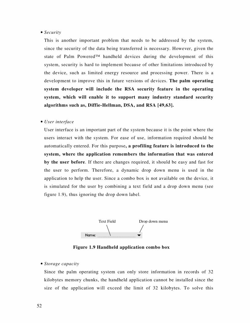
52
• Security
This is another important problem that needs to be addressed by the system,
since the security of the data being transferred is necessary. However, given the
state of Palm Powered™ handheld devices during the development of this
system, security is hard to implement because of other limitations introduced by
the device, such as limited energy resource and processing power. There is a
development to improve this in future versions of devices. The palm operating
system developer will include the RSA security feature in the operating
system, which will enable it to support many industry standard security
algorithms such as, Diffie-Hellman, DSA, and RSA [49,63].
• User interface
User interface is an important part of the system because it is the point where the
users interact with the system. For ease of use, information required should be
automatically entered. For this purpose, a profiling feature is introduced to the
system, where the application remembers the information that was entered
by the user before. If there are changes required, it should be easy and fast for
the user to perform. Therefore, a dynamic drop down menu is used in the
application to help the user. Since a combo box is not available on the device, it
is simulated for the user by combining a text field and a drop down menu (see
figure 1.9), thus ignoring the drop down label.
Figure 1.9 Handheld application combo box
• Storage capacity
Since the palm operating system can only store information in records of 32
kilobytes memory chunks, the handheld application cannot be installed since the
size of the application will exceed the limit of 32 kilobytes. To solve this
Text Field Drop down menu

53
problem, the handheld application code is segmented into multiple sections
that still count as one application. Segmentation occurs at function level,
and functions are grouped based on the operation they perform. An example
of code segmentation where a function called NetInit() is defined to be in section
“comm.”:
#define COMM_SECTION __attribute__ ((section ("comm")))
// function prototype
Err NetInit() COMM_SECTION ;
// function implementation
Err NetInit() {
Err err = 0;
...
return err;
}
The compilation of the application also requires special steps to be performed,
but the steps will not be discussed here.
- 54 -
Chapter 2
Communication Protocol for E-Services
Introduction
The aim of this chapter is to present dynamic protocol interoperability for e-services. The
chapter discusses the following sub-sections:
The formal definition of a State Machine, and description of how client agents that may need
to implement unknown protocols during their lifetime, can dynamically implement these
protocols by loading a state machine definition from a server agent with which it wishes to
communicate. Protocol Correctness deals with the dynamic loading of a state machine in a
“Just-In-Time” manner, which requires that the protocol can be checked for correctness.
Strategies for validating protocol correctness are discussed. State Explosion deals with the
issue of state explosion with protocol validation and commonly used relief strategies. Invalid
State Machines include examples of invalid state machine definitions according to the
proposed validation axioms described in relief strategies. Such an incorrectly defined state
machine must be detected according to protocol correctness strategies. Ontological Data
covers how simple hierarchical ontology and domain specific vocabulary is used to provide
fundamental interoperability between agents operating in the same business domain.
Similarity Matching explains axioms and algorithms, which enable a simple product
brokering negotiation. The proposed approach is implemented to determine the effectiveness
of dynamic conversation interoperability between a client agent and various merchant agents.
Sec 2.1 Related works
Till now a lot of related work has been performed in this area which is as follows:
2.1.1 Agents Framework
In software development, a framework is a defined support structure, in which another
software project can be organized and developed. A framework may include support
programs, code libraries, or a scripting language. There are different proprietary
- 55 -
frameworks that exist, in which agent software can exist and be supported by different type
of host services. These frameworks do not provide interoperability, just physical support, like
mobility and persistence. There are numerous frameworks providing agent-to-host standards
[1], defining how interactivity is possible within agents and the host environment. Interaction
refers to services such as activation, transport and persistence. It is a skeleton upon which
various objects are integrated for a given solution.
There are a few examples of agent frameworks:
• IBM Aglets workbench [2, 3]
This type of Agents frameworks use Java API for creation of mobile agents that can dispatch
to a remote Aglet Framework context for remote execution. These mobile agents pass user
defined messages via synchronous or asynchronous transmission and can locate other agents.
There is one problem with using this framework - it does not provide any coordination
between the agents themselves. To sum up, aglets do not deal with issues like
implementation, coordination, cooperation and coherence [1],
• Voyager [1,4]
Voyager is another tool for creating mobile agents and distributed network applications using
Java features such as serialization, reflection and network services, in which agents pass the
messages for interoperation. It is also good in a mobility point of view but main problem is
related to communication protocols between agents.
• Concordia (Mitsubishi Electric I.T. Centre) [5]
The key features of this framework include platform support such as persistence, security and
mobility. This framework emphasizes the transport mechanism for remotely communicating
agents instead of interoperation between agents. Agents communicate by dynamic invocation
of known method calls. Summing up, Concordia does not provide any methodology to
specify how agents cooperate, coordinate and negotiate to bring about a coherent solution.
• Java Net Agents [6]
Java Net Agents have a similar processing criterion. A fundamental difference is that
knowledge of agent locations and interactions is required, along with their compile time.
- 56 -
• Java Agent Development Framework (JADE)
A FIPA compliant framework, JADE is used to develop agent applications for interoperable
intelligent multi-agent systems. Inter-agent conversations are supported, along with a
distributed agent platform. It also contains a transport mechanism for agent interoperability.
• Workflows and Agent Development Environment (WADE)
An extension of JADE, WADE supports a workflow approach to help manage the complexity
of distribution. The architecture facilitates the administration of a distributed WADE-based
application.
All of the above frameworks use Java agents. Mobility, security and serialization are well
supported due to the centric nature of Java, but interaction with a non-Java agent is not
possible.
2.1.2 Agent Communication Language and FIPA
The Foundation for Intelligent Physical Agents (FIPA) is an IEEE Computer Society
standards organization that promotes agent-based technology and the interoperability of its
standards with other technologies [70]. Its specifications for an ACL encourage the
interoperation of heterogeneous agents.
Communication is not possible anywhere, without a common language, neither in the human
world, nor in computer’s world. Therefore, different type of agents ready for interaction
should have a common understanding of messages in order to interact. The agent
communication language ACL, part of the ARPA Knowledge Sharing Effort [29] consists of
three parts [25]:
1. Vocabulary of domain functions: Here, vocabulary refers to the collection of
known functions which can be used for the interaction purpose between the agents.
For example Bid, Offer and sale etc.
The meaning of the same function can be different for different agents e.g. the
definition of “”Benefit” can be different in the insurance and retail sectors. So
ontologies can be used to map the relationships of data and classes within the
- 57 -
application domain. How a method can be invoked, and by which means, depends on
the ontological context in which it resides.
2. Knowledge Interchange Formalism (KIF): This is an inner layer language which is
used to encode information that is passed between agents. In other words, it provides
knowledge about knowledge using two operators (in particular – the backquote (`)
and comma(,)) and related vocabulary. The following example illustrated in [72]
indicates how these are used.
‘Joe is interested in receiving triples in the salary relation’ is represented as:
(interested joe `(salary, ?x, ?y, ?z))
3. Knowledge Query and Manipulation Language (KQML): KQML is the outer
layer, which allows agents to interact through a sequence of speech acts [25]. A
collection of these speech acts form a complete vocabulary which is understandable
by each agent, thus making communication possible. Each vocabulary word, while
considered individually known as performative and when combined with a list of
arguments forms a language-independent message to another agent.
An example of KQML message transcribed from [25] is as follows:
KQML code fragment
(ask-one
: content (PRICE IBM ? price)
: receiver stock-server
: language LPROLOG
: ontology NYSE-TICKS)
Table 2.1 (a) below describes each of the fields in a statement.
Field Description
Ask-one The performative used to identify the type of message sent to
the receiving agent. This set defines the types of interactions
that can occur between agents supporting KQML.
:content(PRICE IBM ? price) The example format shows a balanced parenthesis format of an
LPROLOG statement querying the price of the IBM stock
- 58 -
price. Both agents must understand the format. For example,
agents that used underlying SQL instead of LYROLOG might
use the following content:
SELECT PRICE FROM STOCK WHERE CODE = “ÏBM
:receiver stock-server A reference to the intended recipient of the KQML message.
:language LPROLOG An identification of the language required for processing of the
content field.
:ontology NYSE-TICKS This statement is used to identify ontology to determine the
context of the required application. An application area may be
described differently by two different ontologies using the same
vocabulary.
Use of such messages will enable KQML – aware agents to interact along with an
understanding of the structure of content as well as the meaning of the request. In this way
agents written in different languages and frameworks can communicate with each other.
2.1.3 Conversation rules
While communication occurs among different agents, having a common communication
language is not enough, there needs to be some pre defined rules and regulations which
specify how communication can be undertaken [7]. These rules and conventions form
communication protocols, which are independent of the language being used.
COOL (COOrdination Language) [7] is a language that defines such communication
conventions in a multi agents system using KQML message exchange. COOL defines
conversation rules, which specify transitions in an FSM (Finite State Machine) model, of a
desired part of conversation. These rules, when aggregated, form classes which detail the
conventions of a communicating protocol. The following code from [7] shows an incomplete
example of LISP- type structure of these conversation rules and conversation classes.
COOL Code fragment(1)
(def-conversation-rule r1
: current-state 2
: received <some KQML message>
- 59 -
: next-state 3
: transmit <some KQML message>)
(def-conversation-class cnv-1
:initiator ? initiator
:respondent ?respondent
:conversation-rules(s0 r1 r2))
COOL Code fragment (2)
(propose
:sender a2
:receiver a1
:content (produce widget 100)
Reply-with r1
: conversation c1)
Agents using these classes effectively use an FSM for all operations like input and output
messages and state transitions, based on the individual conversation rules, whereas multi-
agent systems use COOL for communication purpose.
Conversation protocols are composed of four factors:
1. Finite State Control: This is a set of valid states for all conversations.
2. Input list: A list of used utterances [26,27,28] containing contents of messages.
3. Pushdown List: A list used to verify the responses against previous utterances.
4. Finite Set of Transitions: A collection of valid state transitions.
Agents wishing to communicate with each other do so via an inter-agent mediator. The Java
Interagent for MultiAgent System (JIM) [26, 27] employs conversation protocols to control a
valid conversation. While starting communication an inter-agent mediator of one agent
makes contact with the inter-agent mediator of another. Both inter-agent mediators negotiate
protocols to be used until an agreement is reached.
- 60 -
2.1.4 Internet Interoperability
Previously discussed systems allow interoperability between agents in multi agent systems,
where these systems are executing within a framework of execution for services such as
agent discovery, standardized languages and pre-defined communication protocols.
The Internet is a large heterogeneous environment, with different platforms and no
centralized control of services, nor many data representations and individualistic
communication protocols for services provided. While dealing in an Internet environment, an
agent cannot assume to communicate with only one type of agent, so interoperability
becomes a necessity. We generally use HTTP as an application layer protocol, TCP as the
Transport layer and XML as a data exchange format, but we still need a mechanism for
constructing the meaningful convention of message exchange.
For XML to be used as a standard for data exchange requires the understanding of agents to
parse XML data rather than interpret a language-specific expression. The xCBL (XML
Common Business Library) definitions [8] are a type of library which contains Document
Type Definition (DTD) for XML data exchange between participants in an Internet
environment. Examples of the document types are business terms like “Invoice”, “Price” and
“Tax” which provide interoperability between users in the form of standard data formats, but
there is a need to define the communication protocols.
To form a meaningful business conversation, we need to define that valid sequence of
messages. The valid receipt and dispatch of such typed documents therefore defines an
abstract interface for e-service. The Web Services Conversation Language (WSCL) [9, 10]
provides an XML meta description of the sequence of XML documents that may be used in
document exchange.
Another family of XML based standards is Electronic Business XML, or e-business XML
(ebXML). According to [11], it is sponsored by OASIS and UN/CEFACT, whose mission is
to provide an open, XML-based infrastructure that enables the global use of e-business
- 61 -
information in an interoperable, secure and consistent manner. The architecture allows
concepts and methodologies to be better implemented in e–business solutions.
Another XML-based language, the Web Services Description Language (WSDL) describes
network services as collection of communication endpoints capable of exchanging messages.
On the other hand, the Web Ontology Language (OWL) uses terms, and relationships
between these terms to represent machine interpretable content on the web. Three
sublanguages of OWL exist: OWL Lite, OWL DL and OWL Full, each offering varying
degrees of use and complexity.
For example, the term “Purchase” may be defined as receiving a “PurchaseOrderRQ” and
then sending the “PurchaseOrderAcceptedRS” document and further “Shipping “State.
Abstract interfaces can be defined depending on the different industries. This approach is
intended to provide very loose coupling between protocols and interfaces as a user may
dynamically discover the semantics of the conversation. For example a client can choose
which operation to call first, and to which sequence to progress to, but it is intended that a
conversation definition be defined as an industry standard or agreement between partners.
But in reality, it is static; this does not provide for e-service providers in the same industry
with similar, but different interfaces, to be interoperable.
IBM’s Web Services Flow Language WSFL [11] is an XML-based language to describe the
composition of Web Services. Two types of compositions are considered here. The first one -
Flow Models, are used to determine the structure of a business process. The second type -
Global Model, is used to describe the interaction between partners. Examples of Flow Model
are credit checking, order processing, shipping etc. A simple fragment of XML transcribed
from [11] might be:
<service Provider name =”mySupplier” type =”supplier”>
<locator type =”static” service =”qualitySupply.com/>
</serviceProvider>
By combining these two models, a service user can discover a service interface using well
known document type and required sequencing of web Service usage.
- 62 -
The Simple Object Protocol [12] is designed for the remote procedure calls across the
Internet, where clients pass XML payloads inside HTTP requests, with additional header
information describing method calls to be invoked server side. An application specific server
process, gets data from the XML payload, invokes the request and returns an XML response.
While SOAP provides the means of data transport tunnelled inside a HTTP request, the agent
communication protocol is determined by the required interaction between the traditional
client/server request/response of the underlying objects at either end of the SOAP request.
Similarly, the Simple Commerce Message Protocol (SCMP) [13] is a draft IETF application
protocol which may tunnel requests inside HTTP, and contains a payload of XML data for e-
commerce applications. Services such as data encryption, authentication and reputation are
provided in the protocol specification. It is a requirement that the sending agent create
message payloads in a format acceptable to the receiving agent’s application. The suggested
methods for achieving this are to perform one of the following:
• Have the receiving agent agree to comply with published industry standards.
• Have the receiving agent publish a specification on the services offered, data formats
required, processing rules and other processing behaviour.
• Have the receiving agents implement data according to a specification published by
the sending agent.
• Any combination of the above method.
Currently, these agents must either be written with knowledge of another agent site, or be
trained to interact with it. For example, MySimon.com [14] and MallAgent.com are both
meta search engines and have a database of hundreds of merchant sites. To traverse each site,
the MySimon.com engine, dispatches one agent to each merchant site to produce the final
query results. Each agent dispatched to a merchant site has been specifically trained, by a
human to be able to navigate the site.
2.1.5 Ontology
Ontology consists of relatively generic knowledge that can be reused by different kinds of
applications or tasks. Agent based systems must be able to interoperate without
misunderstanding. There must be a clear understanding of vocabulary terms used. Without
such common understanding, there is a barrier to provide services such as e-commerce [15].
- 63 -
Ontologies are created by domain-experts and Information architects”, [15] to allow agents to
have meaningful communication using domain-specific knowledge.
Due to differing requirements, it is quite difficult to impose a single standard for all. Other
reasons include:
o Even the same industries follow different commercial practices.
o It’s very complex to describe every company’s product and services.
o Placing limitations on business models.
An alternative for this is to develop foundation ontology, which can classifying the basic
concepts for the domain, so it can be used between trading partners. Ontology.Org [16] is an
independent industry and research forum working on the application of ontologies in Internet
commerce. The main aim is related to the problems that impact exchange between e-trading
partners. A common understanding of the basic concepts can be enforced by creation of
XML DTDs (Document Type Definition). However use of XML DTD may be too forgiving
in defining the representation of complex ontology [16] where stronger typing is required, yet
it is a reasonable candidate.
2.2 .1 State Machines
Simply put, a state machine is a system with a set of unique states. According to [68], Finite
State Machines represent a very powerful way of describing and implementing the control
logic for applications. Further, he owes this to a very dense representation, they follow very
simple rules, are easy to verify, and they can be used to generate code. Host special state is its
initial state, but there can be one or more final states. A state machine is useful whenever we
have a program that handles input events and has multiple states depending upon those
events.
An information agent on the Internet may need to interact with many different server agents
during its lifetime. Every merchant agent may provide the same services in its way. The
method of data exchange may be different between a client and the merchant site, and the
conversation protocols involved in exchanging that data. A client agent wishing to interact

- 64 -
with these different agents must be able to determine the message data to be exchanged and
the sequence of messages that determine the conversation protocol between client and server.
Agents interacting via a protocol, send message data in a defined sequence to form the
protocol. Each entity must know what messages are required as input and output and what the
state of processing is between these messages. The behaviour of an entity in this processing is
commonly represented in a state machine. Provided both entities know and adhere to their
respective, validated state machine specifications, the entities can communicate in a valid
manner. The behaviour of each of these processes can be formally modelled as a Labelled
Transition System (LTS). Each LTS of an entity is a state transition diagram containing all
possible reachable states and execution transitions. As described by Cheung and Kramer [17]
a LTS can be described by a four tuples as:
<S, A,∆, Q >
Where:
• S is a set of states in which the entity may exist.
• A is the communicating alphabet of the process. This is the set of input and output
message names that form the valid message types.
• ∆ is a map of state transitions (S x A x S), such that a given state, when applied with a
transition action, will move to another state.
• Q is the initial state for the entity.
Client and server agents’ communication between LTS (or state machines) can be modelled
using these tuples. In the Internet environment, client agents will wish to interact with
different server agents. If the client agent process is to be modelled as an LTS, then this
specification of the LTS must be available to the client agent. [69. It] describes a labelled
transition system as a directed graph with labels on the edges, where states are represented as
vertices, and labelled transition, as the edges with labels. An LTS contains all the states a
component may reach and all the transitions it may perform.
In a distributed environment, each process has proper codes for input and output. As
described by [18] “as protocols evolve to accommodate new requirements, it is cumbersome
if not impossible to upgrade protocol code properly. As a result, protocol often becomes a
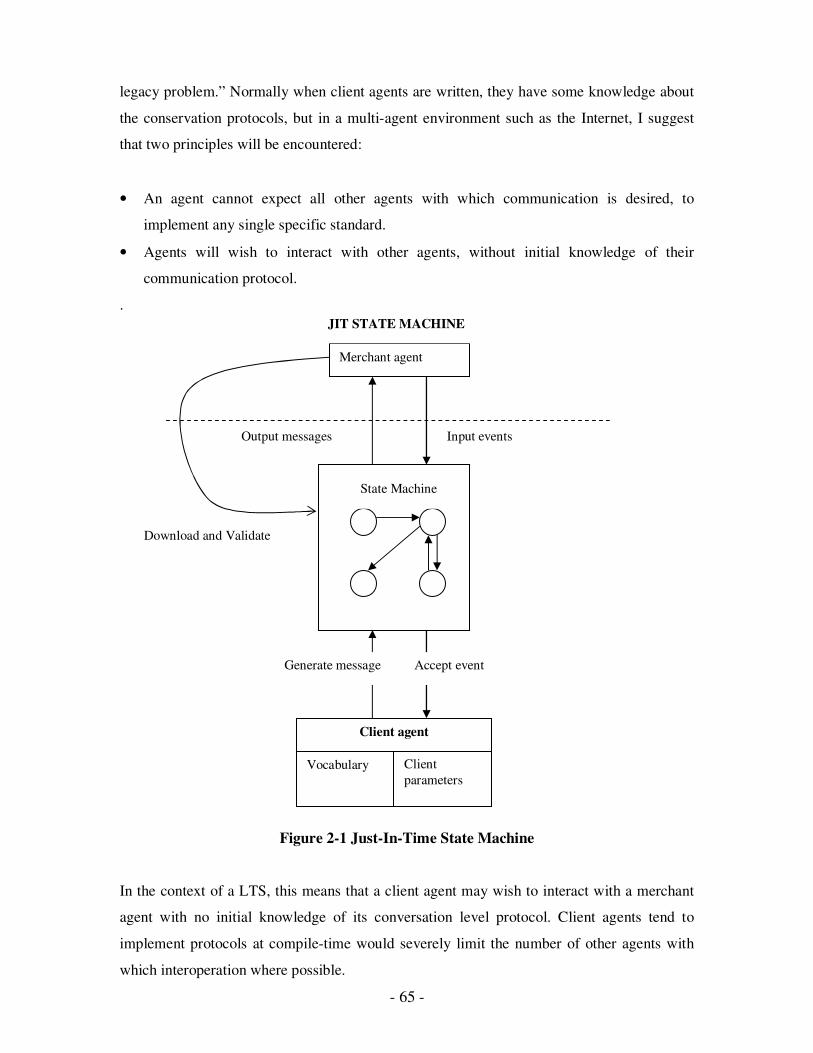
- 65 -
legacy problem.” Normally when client agents are written, they have some knowledge about
the conservation protocols, but in a multi-agent environment such as the Internet, I suggest
that two principles will be encountered:
• An agent cannot expect all other agents with which communication is desired, to
implement any single specific standard.
• Agents will wish to interact with other agents, without initial knowledge of their
communication protocol.
.
Figure 2-1 Just-In-Time State Machine
In the context of a LTS, this means that a client agent may wish to interact with a merchant
agent with no initial knowledge of its conversation level protocol. Client agents tend to
implement protocols at compile-time would severely limit the number of other agents with
which interoperation where possible.
Output messages
Download and Validate
Merchant agent
State Machine
Input events
Accept event Generate message
JIT STATE MACHINE
Client agent
Vocabulary Client
parameters

- 66 -
To solve this problem, I propose that this conversation protocol be implemented by a client
agent dynamically as required. This could be achieved by asking the other agent for a state
machine specification and dynamically implementing the functionality of that state machine.
The client agent could then validate the state machine structure, and dynamically implement
the rules of the state machine to be able to converse with the target merchant agent.
This project only considers the client/server architecture for information agents operating
using only Internet pseudo-standards, but in multi-agent societies, it may be working on a
peer-to-peer basis. The client/server approach is a simpler approach for the initial stage of
dynamically implementing “Just-In-Time” (JIT) conversation level protocols. This is because
a client will only need to learn the required protocol of the server, or multiple servers, as
required. In a true peer-to-peer environment the knowledge of many-to-many relationship of
dynamic protocol implementation is required.
In this context, JIT refers to the compilation technique, which improves runtime performance
by converting code at runtime prior to executing it. Most implementations of Java rely on JIT
compilation for high-speed execution.
Figure 2-1 shows the client downloading a specification, and then using the state machine
to converse with the merchant agent. When a merchant at another site is required, the
client agent can download another state machine specification and repeat the process.
Potentially, the client agent can now converse with any number of merchant agents that
provide a state machine specification for clients. Returning to the formal four tuples
definition of LTS [17], we can analyse the proposal for a JIT State Machine. The following
describes the concept of each tuple, and then a discussion will show some concrete examples.
The four tuples definition is <S, A,∆, Q >
o States <S>
In general, State can be defined as the condition of FSM at a certain time or informally it is
the content of memory. States can be defined as required in the JIT State Machine as
required. A client needs no prior knowledge of the states to be defined. Each state will
require:
- 67 -
• A name eg IDLE, BROWSING, BUYING etc
• A list of valid input events eg Sale, Status
• A list of valid output messages eg Buy, Bid
• Specification of the state(s) to which transition can be made
o Alphabet <A>
In LTS, a vocabulary of known phrases, or message names, used by both ends of a
communicating global FSM is known as alphabets. In this project, we are emphasizing that
the prior knowledge level of agents about each other is. In this case, these primitives
comprise the alphabet, or as I will refer to it, the vocabulary needed to operate with other
agents.
We consider that information agents perform a single specific purpose. For example, one
agent may be created for the purpose of shopping; another agent for the purpose of finding
news articles on specific subjects, another agent may be created for filtering and responding
to email. These agents will need different semantic understanding of the primitives involved
to be pro-active or reactive to their respective tasks. The shopping agent will need to know
the meaning of Buy, Sell, Bid, Offer etc. The newspaper agent will need to know the
meanings of Media, Language, and News Category etc. The email agent will need to know
the meaning of Sender, Receiver, and Copy To, Subject etc. In this case, the first principle is
obeyed since the tasks and responsibilities of each agent are different. Hence, each of them
will have a separate set of standards. However, communication between agents is essential,
thus leading to the second principle.
Each of them needs a common understanding of the messages used for the interaction
purpose in the same domain. The need for vocabulary arises here. In the context of this
project, agents with a small vocabulary will be created to enable interoperation between
agents. It is important to note that whilst it is necessary to have prior knowledge of this
vocabulary (or a subset), it is not necessary to have the knowledge of protocols in advance.
This satisfies the second principle stated earlier, as all agents must interact with each other to
complete their specific tasks.
- 68 -
Vocabulary forms the atomic particles of the conversation level protocol to be dynamically
implemented. While an agent will need to have a semantic understanding of what a primitive
means, it does not need to know how this primitive may need to be combined with other
primitives to form the “unlimited” number of conversation level protocols that may be
specified by all agents encountered.
For example, a shopping agent may know about a primitive called “Bid”. It has a semantic
understanding about what a “Bid” is. It knows that it will vary the value of the Bid until
either a pre-defined bidding criterion has been meeting or a bid has been accepted by a
merchant.
At the lowest vocabulary level, little more needs to be known about what a “Bid” is.
However at the higher protocol level, this “Bid” could be used in a number of different ways.
Depending on the business of a merchant, a “Bid” is a negotiation process over a price
between one merchant and one client, or used in an auction between one merchant and
potentially multiple clients. Even the auction type could be different, employing perhaps
English, Dutch or Calcutta auction type.
o Transition Mapping <∆>
Transition mapping is a process to map or design the possible transitions by a state machine.
A map of state transitions is specified, with each state transition requiring the following
• Current State
• Actions causing the transition (i.e. events)
• Transition State
Some state machines are easier to implement than others. The easiest state machine to
implement is a deterministic state machine. This means that for each state and action
combination, there may only be transition to one other single state. As formally defined by
[17], a state machine is deterministic if, and only if:
∀ s, s’ and s’’ ∈ S,
(s, a, s’) ∈ ∆ ^ (s, a, s’’) ∈ ∆ ⇒ (s’ = s’’)
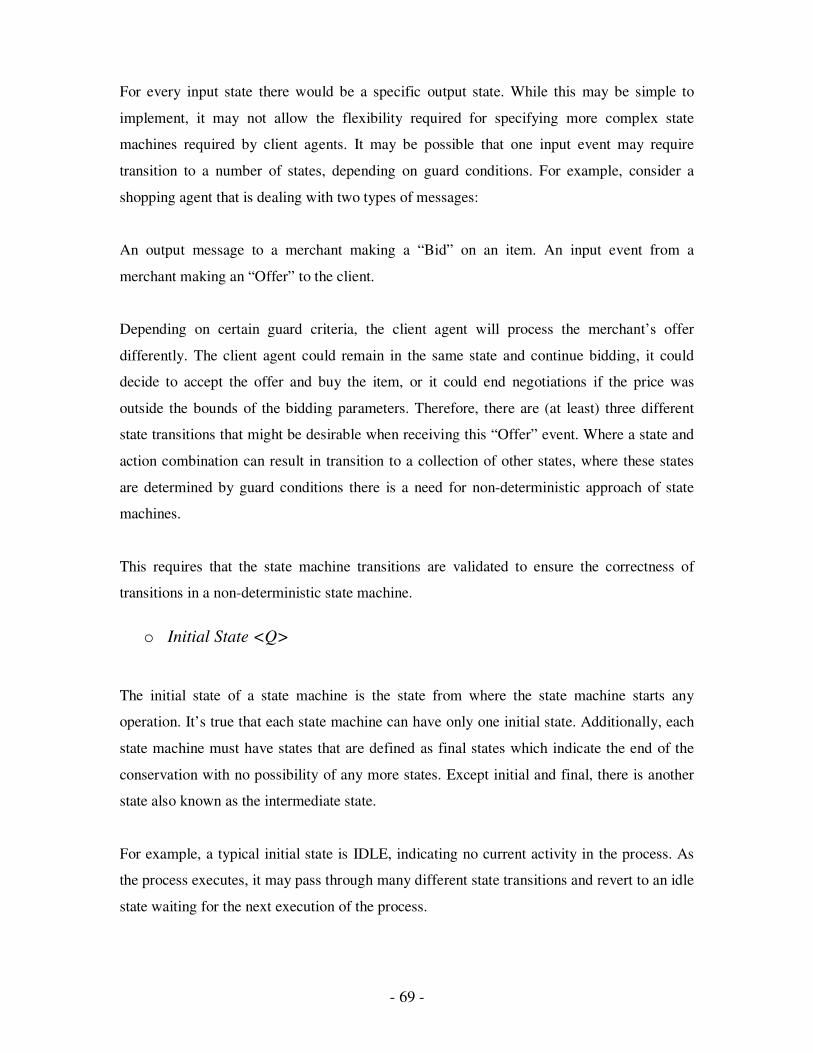
- 69 -
For every input state there would be a specific output state. While this may be simple to
implement, it may not allow the flexibility required for specifying more complex state
machines required by client agents. It may be possible that one input event may require
transition to a number of states, depending on guard conditions. For example, consider a
shopping agent that is dealing with two types of messages:
An output message to a merchant making a “Bid” on an item. An input event from a
merchant making an “Offer” to the client.
Depending on certain guard criteria, the client agent will process the merchant’s offer
differently. The client agent could remain in the same state and continue bidding, it could
decide to accept the offer and buy the item, or it could end negotiations if the price was
outside the bounds of the bidding parameters. Therefore, there are (at least) three different
state transitions that might be desirable when receiving this “Offer” event. Where a state and
action combination can result in transition to a collection of other states, where these states
are determined by guard conditions there is a need for non-deterministic approach of state
machines.
This requires that the state machine transitions are validated to ensure the correctness of
transitions in a non-deterministic state machine.
o Initial State <Q>
The initial state of a state machine is the state from where the state machine starts any
operation. It’s true that each state machine can have only one initial state. Additionally, each
state machine must have states that are defined as final states which indicate the end of the
conservation with no possibility of any more states. Except initial and final, there is another
state also known as the intermediate state.
For example, a typical initial state is IDLE, indicating no current activity in the process. As
the process executes, it may pass through many different state transitions and revert to an idle
state waiting for the next execution of the process.
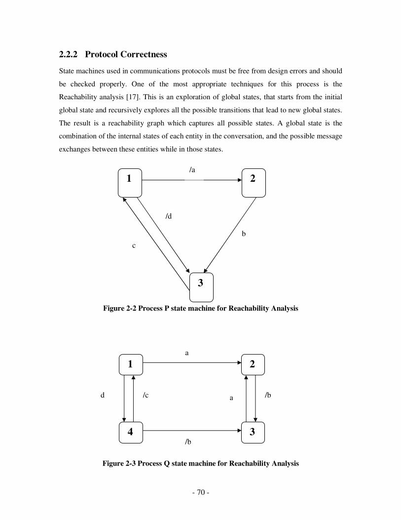
- 70 -
2.2.2 Protocol Correctness
State machines used in communications protocols must be free from design errors and should
be checked properly. One of the most appropriate techniques for this process is the
Reachability analysis [17]. This is an exploration of global states, that starts from the initial
global state and recursively explores all the possible transitions that lead to new global states.
The result is a reachability graph which captures all possible states. A global state is the
combination of the internal states of each entity in the conversation, and the possible message
exchanges between these entities while in those states.
Figure 2-2 Process P state machine for Reachability Analysis
Figure 2-3 Process Q state machine for Reachability Analysis
1
4 3
2
a
a /b
/b
d /c
1 2
3
/a
b
c
/d

- 71 -
Use of reachability analysis attempts to explore the possible global states of a multi-entity
protocol to check for design errors. For example, consider a two-entity communications
protocol with processes P and Q. Each entity has its own state machine, combining to form
the communication protocol. For example, the state transition diagrams in
Figure 2-2 and Figure 2-3, input events are represented by letters (eg ‘b’) and output messages represented
using a slash (eg ‘/d’).
If we represent a global state in this reachability graph as in Figure 2-4:
Figure 2-4 Global State Representation
The potential problems that can be shown by reachability graph are Deadlocks,
Unspecified reception, Livelock and Non-executable transitions.
Deadlocks: A set of processes is deadlocked if each process in the set is waiting for an
event that only another process in the set can cause (including itself). No process in the
protocol will perform a transition to another state.
Unspecified Reception: A node encounters an input message for a state machine process that
does not have specification for that input message.
Livelock: Processes continually exchange the same messages and do not any progress
towards protocol completion. While cycles are allowed in graphs, some mechanism must be
employed to ensure that these cycles are intentional and controlled.
Non-executable transitions: Non executable transitions as the name suggests are dead code,
states or state transitions that cannot be reached.
P state P->Q message
Q->P message Q state
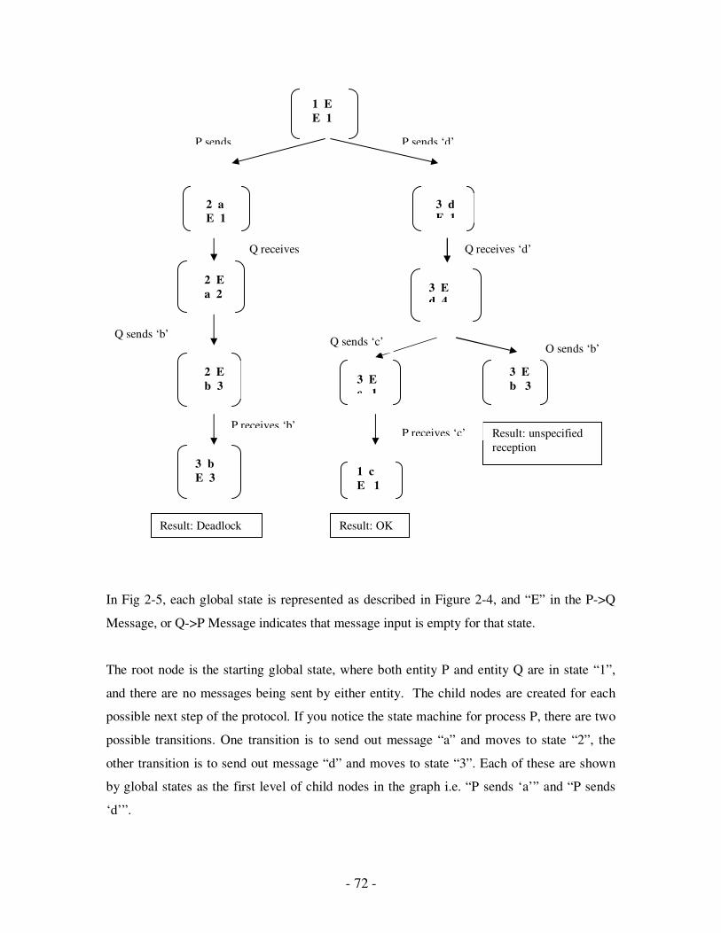
- 72 -
In Fig 2-5, each global state is represented as described in Figure 2-4, and “E” in the P->Q
Message, or Q->P Message indicates that message input is empty for that state.
The root node is the starting global state, where both entity P and entity Q are in state “1”,
and there are no messages being sent by either entity. The child nodes are created for each
possible next step of the protocol. If you notice the state machine for process P, there are two
possible transitions. One transition is to send out message “a” and moves to state “2”, the
other transition is to send out message “d” and moves to state “3”. Each of these are shown
by global states as the first level of child nodes in the graph i.e. “P sends ‘a’” and “P sends
‘d’”.
1 E
E 1
2 a
E 1
2 E
a 2
2 E
b 3
3 b
E 3
3 d E 1
3 E d 4
3 E
c 1
1 c
E 1
3 E
b 3
Result: Deadlock
Result: unspecified
reception
Result: OK
P sends P sends ‘d’
Q receives ‘a’
Q sends ‘b’
P receives ‘b’
Q receives ‘d’
Q sends ‘c’ Q sends ‘b’
P receives ‘c’
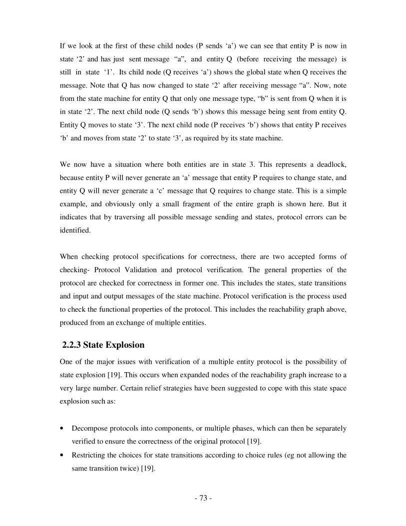
- 73 -
If we look at the first of these child nodes (P sends ‘a’) we can see that entity P is now in
state ‘2’ and has just sent message “a”, and entity Q (before receiving the message) is
still in state ‘1’. Its child node (Q receives ‘a’) shows the global state when Q receives the
message. Note that Q has now changed to state ‘2’ after receiving message “a”. Now, note
from the state machine for entity Q that only one message type, “b” is sent from Q when it is
in state ‘2’. The next child node (Q sends ‘b’) shows this message being sent from entity Q.
Entity Q moves to state ‘3’. The next child node (P receives ‘b’) shows that entity P receives
‘b’ and moves from state ‘2’ to state ‘3’, as required by its state machine.
We now have a situation where both entities are in state 3. This represents a deadlock,
because entity P will never generate an ‘a’ message that entity P requires to change state, and
entity Q will never generate a ‘c’ message that Q requires to change state. This is a simple
example, and obviously only a small fragment of the entire graph is shown here. But it
indicates that by traversing all possible message sending and states, protocol errors can be
identified.
When checking protocol specifications for correctness, there are two accepted forms of
checking- Protocol Validation and protocol verification. The general properties of the
protocol are checked for correctness in former one. This includes the states, state transitions
and input and output messages of the state machine. Protocol verification is the process used
to check the functional properties of the protocol. This includes the reachability graph above,
produced from an exchange of multiple entities.
2.2.3 State Explosion
One of the major issues with verification of a multiple entity protocol is the possibility of
state explosion [19]. This occurs when expanded nodes of the reachability graph increase to a
very large number. Certain relief strategies have been suggested to cope with this state space
explosion such as:
• Decompose protocols into components, or multiple phases, which can then be separately
verified to ensure the correctness of the original protocol [19].
• Restricting the choices for state transitions according to choice rules (eg not allowing the
same transition twice) [19].

- 74 -
• Simplify reachability analysis by restricting the analysis to only two-entity protocols. [27]
This reduces the number of possible global states.
• Implement a depth-first search of the state space using heuristic searches common in
Artificial Intelligence models.
• Acyclic protocol validation, which grows each entity in a protocol to check for design
errors, rather than creating a graph of global states with possible cycles [17]. Errors can
still be detected with a sufficiently sophisticated search.
Testing for protocol correctness may be a complex process. For this project, I am proposing a
client to use a state machine provided to it by a server agent on the Internet. This should
allow us to simplify any checking that should be done by the client, for the following
reasons:
• Clients use the protocol to test and verify it for the server site.
• The client will still wish to validate the client state machine, as a client state machine
with incorrect properties (eg state transition structure) may lead to incorrect processing in
the client agent.
• Stateless servers are generally used on the Internet. We suggest that merchant servers in
an Internet B2C environment would be designed as stateless servers. This is partly a
product of the stateless HTTP application layer protocol used across the Internet and
partly because it is undesirable for such servers to maintain the state of many clients. For
example, the SET (Secure Electronic Transaction) protocol[20] used for payment
authorization, and payment capture, uses a series of tokens produced by the server
process and passed back to the client. This token can be later passes it back to the server
process as a state representation.
These points allow us to simplify the correctness checking to only client-side validation of
the client state machine. Providing message names for state transitions are correct in the
downloaded XML file from the merchant server:
� Deadlocks will not occur because the client is receiving and displaying valid message
names and the server is stateless and therefore will not get deadlocked.
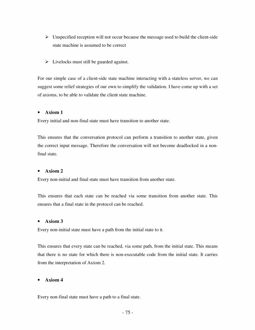
- 75 -
� Unspecified reception will not occur because the message used to build the client-side
state machine is assumed to be correct
� Livelocks must still be guarded against.
For our simple case of a client-side state machine interacting with a stateless server, we can
suggest some relief strategies of our own to simplify the validation. I have come up with a set
of axioms, to be able to validate the client state machine.
• Axiom 1
Every initial and non-final state must have transition to another state.
This ensures that the conversation protocol can perform a transition to another state, given
the correct input message. Therefore the conversation will not become deadlocked in a non-
final state.
• Axiom 2
Every non-initial and final state must have transition from another state.
This ensures that each state can be reached via some transition from another state. This
ensures that a final state in the protocol can be reached.
• Axiom 3
Every non-initial state must have a path from the initial state to it.
This ensures that every state can be reached, via some path, from the initial state. This means
that there is no state for which there is non-executable code from the initial state. It carries
from the interpretation of Axiom 2.
• Axiom 4
Every non-final state must have a path to a final state.

- 76 -
This ensures that once a state is reached that the conversation protocol can successfully
complete upon some sequence of messages.
If we combine Axiom 3 and Axiom 4 it ensures that for every intermediate state:
• The intermediate state is reachable from the initial state
• The final state is reachable from the intermediate state
Therefore, there is a path from initial state to a final state through each intermediate state.
If this is correct, and we have made the initial acceptance that transition message names in
the downloaded file are correct, then we can be satisfied that the client state machine is
validated for use with the merchant server.
Figures 2-6(a), 2-6(b), 2-6(c), 2-6(d) illustrate the various state transitions
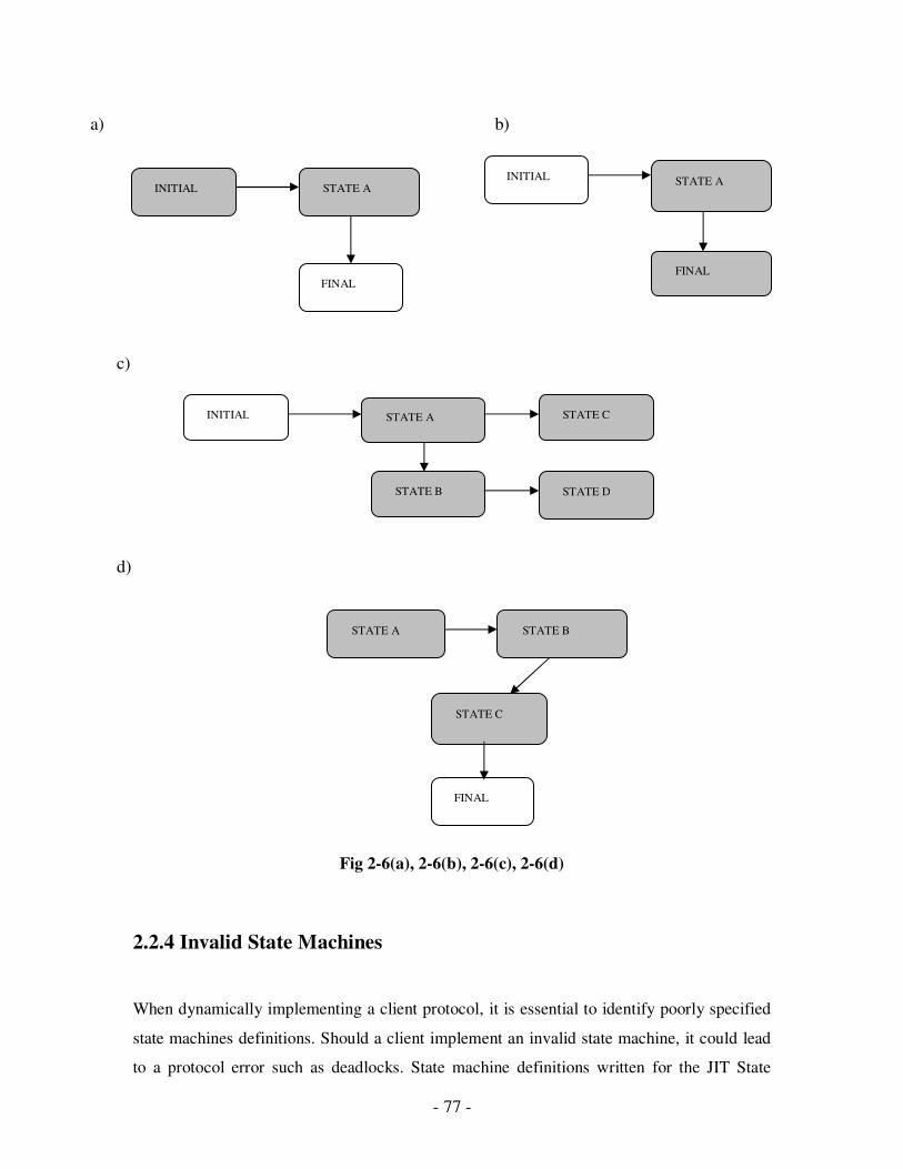
- 77 -
Fig 2-6(a), 2-6(b), 2-6(c), 2-6(d)
2.2.4 Invalid State Machines
When dynamically implementing a client protocol, it is essential to identify poorly specified
state machines definitions. Should a client implement an invalid state machine, it could lead
to a protocol error such as deadlocks. State machine definitions written for the JIT State
INITIAL
FINAL
STATE A INITIAL
FINAL
STATE A
INITIAL
STATE B
STATE A STATE C
STATE D
FINAL
STATE A STATE B
STATE C
a) b)
c)
d)

- 78 -
Machine will be specified using XML. An XML author could easily write an incorrect
specification. The axioms stated in the previous section will identify these poorly specified
state machine definitions. Following are two examples of invalid state machines that will be
detected by the axioms.
The state machine in Figure 2-77(a) is invalid as both STATE A and STATE B cannot reach
a final state. This violates Axiom 1.
The state machine in Figure 2-77(b) is invalid because STATE C cannot be reached from the
initial state. This violates Axiom 3.
Figure 2-7 (a), 2.7(b) Invalid State Machine Examples
2.2.5 Ontological Data
Due to the probability of different data relationships across a business domain, data and their
relationships must have some commonality across the domain if we wish to ensure
interoperability with numerous different agents. In the context of this project, this means that
server agents representing different merchant web sites must have some commonality if they
expect a generic domain-specific client agent to be able to interact with it.
Implementations of industry standards may not be possible. Different companies use different
representations of data and terminology to describe fundamental business concepts.
Adherence to an imposed standard may restrict any individual company’s business model.
However, business in the same domain would expect to understand the fundamental business
principles of their business domain. For example, two Insurance companies will almost
INITIAL
STATE
STATE
FINAL
INITIAL
STATE B
STATE A
FINAL STATE C
a) b)

- 79 -
certainly have different internal data formats, procedures and relationships, but still have an
understanding of the fundamental domain concepts of such things as Premium, Reinsurance,
Claims, and Disability etc. This implies the there needs to be some mapping between
accepted domain ontology of fundamental concepts, and an internal implementation of the
business processes.
2.2.6 Similarity Matching
Because there may be different internal representations of a fundamental domain concept, we
require a method to calculate the similarity of any two different requests. Such a calculation
would be required to calculate the similarity between different requests. A simple example is
a request for a sale item that a merchant does not have. That merchant could compare the
similarity of each of the items it does have, with the original request.
In a simple merchant domain, it raises the question of similarity matching. A domain-specific
client may issue a request of those maps to a similar product or service known to a merchant
server. Therefore, a server agent must have some way to compare the similarity of a request
from a client, to the known internal structure in the server. This could involve a series of
negotiations between the client and server agents, attempting to refine the search for a
requested product or service. In the same way that negotiation can occur regarding protocol
specification during a handshake process, there should be support for the process of offer and
counter offer when requesting products or services.
Similarity matching can be implemented using a tree structure containing nodes with a
feature vector at each node used for similarity comparison, such as calculating the nearest
neighbour problem by [21] or Similarity Indexing using feature vectors by [22].
I will consider similarity matching using a simple acyclic tree and feature vectors containing
domain-specific similarity values. Each feature vector will contain a feature value for each
level of hierarchy. For example a node at depth 3 in a tree, would have a feature vector of
length 3, representing a feature value for itself and its two ancestor nodes. Such values would
be expected to be created by a domain expert.
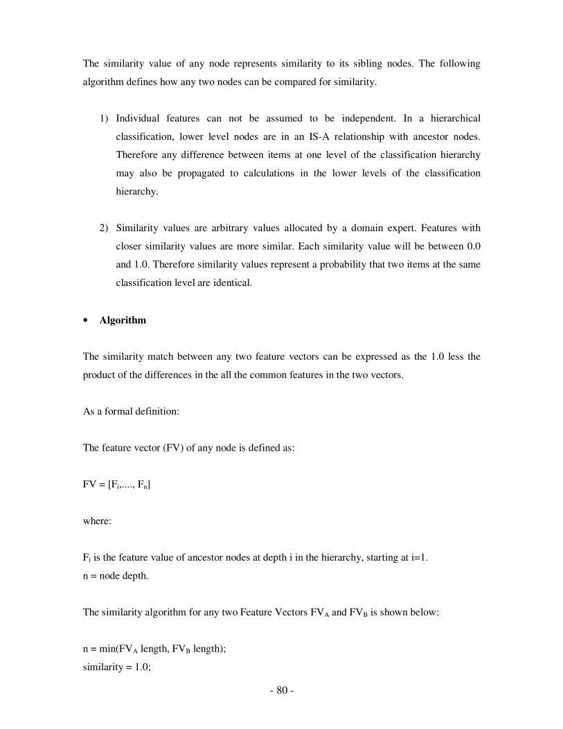
- 80 -
The similarity value of any node represents similarity to its sibling nodes. The following
algorithm defines how any two nodes can be compared for similarity.
1) Individual features can not be assumed to be independent. In a hierarchical
classification, lower level nodes are in an IS-A relationship with ancestor nodes.
Therefore any difference between items at one level of the classification hierarchy
may also be propagated to calculations in the lower levels of the classification
hierarchy.
2) Similarity values are arbitrary values allocated by a domain expert. Features with
closer similarity values are more similar. Each similarity value will be between 0.0
and 1.0. Therefore similarity values represent a probability that two items at the same
classification level are identical.
• Algorithm
The similarity match between any two feature vectors can be expressed as the 1.0 less the
product of the differences in the all the common features in the two vectors.
As a formal definition:
The feature vector (FV) of any node is defined as:
FV = [Fi,...., Fn]
where:
Fi is the feature value of ancestor nodes at depth i in the hierarchy, starting at i=1.
n = node depth.
The similarity algorithm for any two Feature Vectors FVA and FVB is shown below:
n = min(FVA length, FVB length);
similarity = 1.0;

- 81 -
for (i=1;i<=n;i++) {
similarity *= (1.0 – (abs(FVA[i] – FVB[i])));
}
Figure 2.8 Similarity Equation
This algorithm implies that similarity matching can only be applied to the level of speciality
shared by the two nodes in the hierarchy. For example, a node of depth 5 can only be
compared to a node of depth 3, with the first three features in their feature vectors. As the
depth of nodes increases, similarity between nodes becomes more distinct. In other words, a
more precise value is obtained when nodes with high depths are used in the above equation.
This does not necessarily mean that they are less, or more similar, thus resulting in a higher
degree of accuracy for the similarity value.
The above algorithm has been used, instead of a formula, due to its ease of use in the
examples that follow. Further, a different approach, such as a Euclidean measure, or
Minkowski distance was not employed for the same reason.
Following is an example of dissimilarity and similarity calculation, using example feature
vectors for siblings from Table 2-1 (b).
Table 2-1 (b) Sibling similarity example
Part Feature Value
A 1.0
B 0.7
C 0.7
D 0.5
Dissimilarity between any two siblings is simply the difference between their feature values.
This feature may represent quality, price or any other property determined by a domain
expert. The similarity is simply 1.0 minus the dissimilarity.
Therefore, two identical nodes would have a dissimilarity value of 0.0 and a similarity value
of 1.0. In this sense, the differences between the feature values represent a distance function
between the components. So, Table 2-1 (b) would calculate similarities between nodes as the
following simple distance functions shown in Table 2-2.
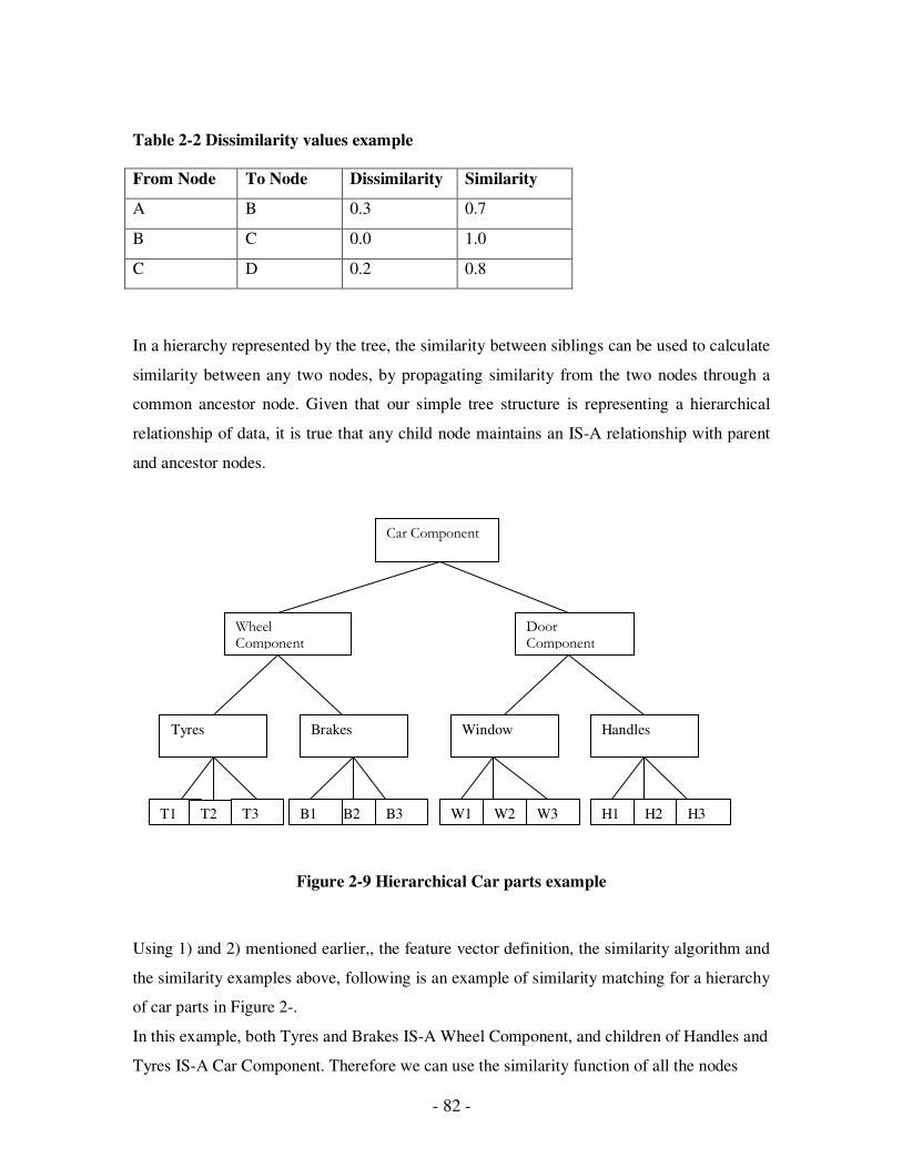
- 82 -
Table 2-2 Dissimilarity values example
From Node To Node Dissimilarity Similarity
A B 0.3 0.7
B C 0.0 1.0
C D 0.2 0.8
In a hierarchy represented by the tree, the similarity between siblings can be used to calculate
similarity between any two nodes, by propagating similarity from the two nodes through a
common ancestor node. Given that our simple tree structure is representing a hierarchical
relationship of data, it is true that any child node maintains an IS-A relationship with parent
and ancestor nodes.
Figure 2-9 Hierarchical Car parts example
Using 1) and 2) mentioned earlier,, the feature vector definition, the similarity algorithm and
the similarity examples above, following is an example of similarity matching for a hierarchy
of car parts in Figure 2-.
In this example, both Tyres and Brakes IS-A Wheel Component, and children of Handles and
Tyres IS-A Car Component. Therefore we can use the similarity function of all the nodes
Car Component
Wheel Component
Door Component
Tyres Brakes Window Handles
T1 T2 T3 B2 B3 B1 W1 W2 W3 H1 H2 H3
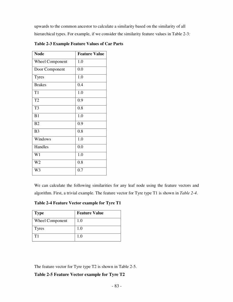
- 83 -
upwards to the common ancestor to calculate a similarity based on the similarity of all
hierarchical types. For example, if we consider the similarity feature values in Table 2-3:
Table 2-3 Example Feature Values of Car Parts
Node Feature Value
Wheel Component 1.0
Door Component 0.0
Tyres 1.0
Brakes 0.4
T1 1.0
T2 0.9
T3 0.8
B1 1.0
B2 0.9
B3 0.8
Windows 1.0
Handles 0.0
W1 1.0
W2 0.8
W3 0.7
We can calculate the following similarities for any leaf node using the feature vectors and
algorithm. First, a trivial example. The feature vector for Tyre type T1 is shown in Table 2-4.
Table 2-4 Feature Vector example for Tyre T1
Type Feature Value
Wheel Component 1.0
Tyres 1.0
T1 1.0
The feature vector for Tyre type T2 is shown in Table 2-5.
Table 2-5 Feature Vector example for Tyre T2

- 84 -
Type Feature Value
Wheel Component 1.0
Tyres 1.0
T1 0.9
Therefore we calculate the similarity as a product of the similarity of off the levels of
hierarchy as in Table 2-6.
Table 2-6 Similarity calculation for T1 and T2
T1 Type Feature
Value
T2 Type Feature
Value
Dissimilarity Similarity
Wheel
Component
1.0 Wheel
Component
1.0 0.0 1.0
Tyres 1.0 Tyres 1.0 0.0 1.0
T1 1.0 T2 0.9 0.1 0.9
And the similarity between T1 and T2 is 1.0 * 1.0 * 0.9 = 0.9
If we wanted to compare nodes that are not siblings, such as a type T2 of Tyre and a type B3
of Brake, the mechanism is the same.
The feature vector for Tyre type T2 is shown in Table 2-7.
Table 2-7 Feature Vector example for Tyre T2
Type Feature Value
Wheel Component 1.0
Tyres 1.0
T2 0.9
The feature vector for Brake type B3 is shown in Table 2-8.
Table 2-8 Feature Vector example for Brake B3
Type Feature Value
Wheel Component 1.0
Brakes 0.4
B3 0.8

- 85 -
We calculate the similarity as a product of the similarity of off the levels of hierarchy as
Table 2-9.
Table 2-9 Similarity calculation for T2 and B3
T2 Type Feature
Value
B3 Type Feature
Value
Dissimilarity Similarity
Wheel
Component
1.0 Wheel
Component
1.0 0.0 1.0
Tyres 1.0 Brakes 0.4 0.6 0.4
T2 0.9 B3 0.8 0.1 0.9
Therefore the similarity is 1.0 * 0.4 * 0.9 = 0.36
In this example, this is a reasonable similarity, given that Tyres and Brakes are closely
related in the operation of a car wheel, but are specifically different items. To determine
whether an item might be an acceptable match based on similarity alone, threshold values
may be employed.
If we traverse ancestor nodes with no similarity, we would expect no similarity between the
two nodes being compared. Consider an example of comparing similarity between a specific
Tyre T2 and a specific Window W2. The resultant similarity is shown in Table 2-10.
Table 2-10 Similarity calculation example for T2 and W2
T2 Type Feature
Value
W2Type Feature
Value
Dissimilarity Similarity
Wheel
Component
1.0 Door
Component
0.0 1.0 0.0
Tyres 1.0 Window 1.0 0.0 1.0
T2 0.9 W2 0.8 0.1 0.9
So, the similarity is 0.0 * 1.0 * 0.9 = 0.0
This example indicates that for there to be any degree of similarity between items, there must
exist somewhere in their ancestry, siblings with a non-zero degree of similarity. In any
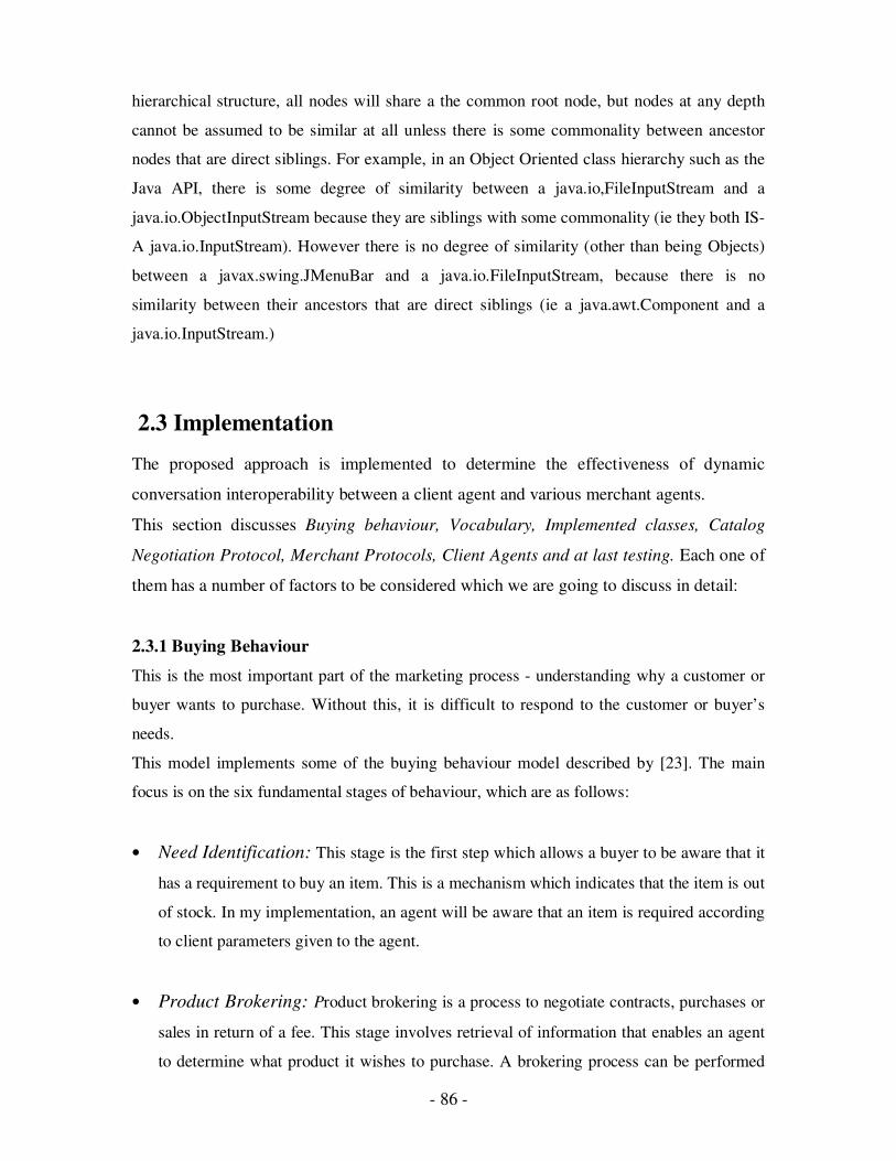
- 86 -
hierarchical structure, all nodes will share a the common root node, but nodes at any depth
cannot be assumed to be similar at all unless there is some commonality between ancestor
nodes that are direct siblings. For example, in an Object Oriented class hierarchy such as the
Java API, there is some degree of similarity between a java.io,FileInputStream and a
java.io.ObjectInputStream because they are siblings with some commonality (ie they both IS-
A java.io.InputStream). However there is no degree of similarity (other than being Objects)
between a javax.swing.JMenuBar and a java.io.FileInputStream, because there is no
similarity between their ancestors that are direct siblings (ie a java.awt.Component and a
java.io.InputStream.)
2.3 Implementation
The proposed approach is implemented to determine the effectiveness of dynamic
conversation interoperability between a client agent and various merchant agents.
This section discusses Buying behaviour, Vocabulary, Implemented classes, Catalog
Negotiation Protocol, Merchant Protocols, Client Agents and at last testing. Each one of
them has a number of factors to be considered which we are going to discuss in detail:
2.3.1 Buying Behaviour
This is the most important part of the marketing process - understanding why a customer or
buyer wants to purchase. Without this, it is difficult to respond to the customer or buyer’s
needs.
This model implements some of the buying behaviour model described by [23]. The main
focus is on the six fundamental stages of behaviour, which are as follows:
• Need Identification: This stage is the first step which allows a buyer to be aware that it
has a requirement to buy an item. This is a mechanism which indicates that the item is out
of stock. In my implementation, an agent will be aware that an item is required according
to client parameters given to the agent.
• Product Brokering: Product brokering is a process to negotiate contracts, purchases or
sales in return of a fee. This stage involves retrieval of information that enables an agent
to determine what product it wishes to purchase. A brokering process can be performed
- 87 -
with a merchant to determine the specifics of a required item. This brokering may involve
multiple requests to a merchant for more detailed information, or perhaps for information
on products similar to a requested item.
My implementation involves a client being able to browse a catalog of merchant
information, and then make further refined queries based on the information received. The
result of product brokering will be a specific item selected from an initial generic keyword
query.
• Merchant Brokering: This stage involves the selection of a merchant from which to
purchase an item. In my prototype implementation, three merchants are used. An agent
uses price to determine the merchant from which to buy. Buying behaviour could
potentially include other buyer-defined criteria such as warranty, delivery time, previous
buying history, merchant reputation etc.
• Negotiation: The process of bargaining that precedes an agreement. This stage
determines how a client agent and merchant determine the price of a requested item. We
use different techniques, depending on the business domain, in which to set a price, such
as fixed price, price negotiation and numerous auction procedures. The types of
negotiations possible are determined by the vocabulary supported by client and merchant
agents.
• Purchase and Delivery: This stage deals with finalizing the purchase and describing
delivery options. In my implementation, purchasing is performed in a way appropriate to
the particular protocol specified by the merchant. I have not implemented any delivery
options information as part of this prototype, as they are not relevant to the dynamic
protocols I am investigating.
• Product Service and Evaluation. This involves a customer evaluating the service
received from the merchant and the satisfaction of the product purchased. In a
sophisticated shopping agent system, a client agent could maintain some buying history
about merchants and products, and then use that as feedback into later invocations of the
Merchant brokering stage of buying. In my implementation, this project is looking at
- 88 -
protocols between agents in a distributed system, and the evaluation and feed back
appropriate to this stage are not relevant in the context of the project.
2.3 .2 Vocabulary
A supply of expressive means or a repertoire of communication is used by agents wishing
to participate in communication in this domain. Each vocabulary term represents a
fundamental concept in the domain. Implementation of each concept is independent of other
vocabulary terms. In the context of a finite state machine, they will represent input events, or
output messages used between state transitions. Finite State Machines will vary from one
merchant server agent to the next. This composition of terms and states is used to form the
communication protocol between agents interoperating in this domain.
The following phrase definitions are defined in terms of the business domain, as fundamental
business concepts. This intention is to demonstrate the possibility of reusable core domain
primitives that may be used in an ontological sense rather than a specific implementation.
• Catalog: A Catalog phrase is a request for a listing of catalog items. A request can be
formed from a simple keyword query such as “Shiraz”, which implies a request for a list
of syntactically matching items. A request can also be formed using a specific reference
item returned from a previous catalog request. This implies a request for a list of similarly
matched items.
• CatalogItems: A CatalogItems phrase is a response to a request for a Catalog. This
request may ask for either a syntax match or a similarity match. Items returned from a
similarity match will be ranked in descending order of similarity to the reference item.
• Bid: in actual terms an offer or proposal of a price. A Bid is a monetary value that a
purchaser is willing to pay for a specific item. The issuer makes a genuine contract of
willingness to pay the specified price. Should the selling agent accept the bid, the buying
agent will be obliged to a transaction at the specified Bid price. When Bid values do not
change in consecutive Bids, it can be assumed that the bidder has reached a final limit on
the Bid value. Depending on the method of bidding currently invoked, the value may
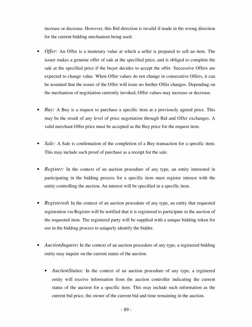
- 89 -
increase or decrease. However, this Bid direction is invalid if made in the wrong direction
for the current bidding mechanism being used.
• Offer: An Offer is a monetary value at which a seller is prepared to sell an item. The
issuer makes a genuine offer of sale at the specified price, and is obliged to complete the
sale at the specified price if the buyer decides to accept the offer. Successive Offers are
expected to change value. When Offer values do not change in consecutive Offers, it can
be assumed that the issuer of the Offer will issue no further Offer changes. Depending on
the mechanism of negotiation currently invoked, Offer values may increase or decrease.
• Buy: A Buy is a request to purchase a specific item at a previously agreed price. This
may be the result of any level of price negotiation through Bid and Offer exchanges. A
valid merchant Offer price must be accepted as the Buy price for the request item.
• Sale: A Sale is confirmation of the completion of a Buy transaction for a specific item.
This may include such proof of purchase as a receipt for the sale.
• Register: In the context of an auction procedure of any type, an entity interested in
participating in the bidding process for a specific item must register interest with the
entity controlling the auction. An interest will be specified in a specific item.
• Registered: In the context of an auction procedure of any type, an entity that requested
registration via Register will be notified that it is registered to participate in the auction of
the requested item. The registered party will be supplied with a unique bidding token for
use in the bidding process to uniquely identify the bidder.
• AuctionInquire: In the context of an auction procedure of any type, a registered bidding
entity may inquire on the current status of the auction.
• AuctionStatus: In the context of an auction procedure of any type, a registered
entity will receive information from the auction controller indicating the current
status of the auction for a specific item. This may include such information as the
current bid price, the owner of the current bid and time remaining in the auction.
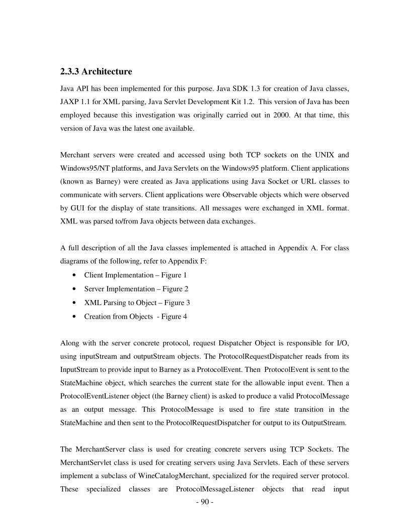
- 90 -
2.3.3 Architecture
Java API has been implemented for this purpose. Java SDK 1.3 for creation of Java classes,
JAXP 1.1 for XML parsing, Java Servlet Development Kit 1.2. This version of Java has been
employed because this investigation was originally carried out in 2000. At that time, this
version of Java was the latest one available.
Merchant servers were created and accessed using both TCP sockets on the UNIX and
Windows95/NT platforms, and Java Servlets on the Windows95 platform. Client applications
(known as Barney) were created as Java applications using Java Socket or URL classes to
communicate with servers. Client applications were Observable objects which were observed
by GUI for the display of state transitions. All messages were exchanged in XML format.
XML was parsed to/from Java objects between data exchanges.
A full description of all the Java classes implemented is attached in Appendix A. For class
diagrams of the following, refer to Appendix F:
• Client Implementation – Figure 1
• Server Implementation – Figure 2
• XML Parsing to Object – Figure 3
• Creation from Objects - Figure 4
Along with the server concrete protocol, request Dispatcher Object is responsible for I/O,
using inputStream and outputStream objects. The ProtocolRequestDispatcher reads from its
InputStream to provide input to Barney as a ProtocolEvent. Then ProtocolEvent is sent to the
StateMachine object, which searches the current state for the allowable input event. Then a
ProtocolEventListener object (the Barney client) is asked to produce a valid ProtocolMessage
as an output message. This ProtocolMessage is used to fire state transition in the
StateMachine and then sent to the ProtocolRequestDispatcher for output to its OutputStream.
The MerchantServer class is used for creating concrete servers using TCP Sockets. The
MerchantServlet class is used for creating servers using Java Servlets. Each of these servers
implement a subclass of WineCatalogMerchant, specialized for the required server protocol.
These specialized classes are ProtocolMessageListener objects that read input

- 91 -
ProtocolMessages from an InputStream, and return a ProtocolEvent to be sent back to the
client. Because servers are stateless, there is no StateMachine object.
XML files are used by servers for ontology hierarchies, wine catalogs and state machine
definitions.
The Builder pattern [24] is used to build any valid ProtocolMessage or ProtocolEvent type
from parsed XML The class diagram for parsing input XML and building ProtocolEvent
objects in the client and ProtocolMessages in the servers is given in Appendix F – Fig. 3.
The SAXDirector is responsible for parsing XML, and sending data to a concrete
DataBuilder object to build an object. Depending on the type of input, either a
ProtocolMessageBuilder or ProtocolEventBuilder object use a ProtocolMessageFactory or
ProtocolEventFactory to instantiate an object and populate it with data received from the
SAXDirector. This allows parsed XML to build any recognized event or message type.
XML data from any known object type can be created by using builder pattern [24]. The
ObjectDirector object knows of one Object that it wants to convert into XML. This will be a
ProtocolMessage or ProtocolEvent object. Using Java reflection, properties from the object
are obtained and used to build XML data. A DataBuilder subclass responsible for
transforming XML accepts the data and writes well-formed XML tag data.
2.3.4 Catalog Negotiation Protocol
Negotiation is essential between interoperable agents. In this context, it refers to the
establishment of a common understanding of a concept or implementation, rather than (for
example) negotiation over a merchant’s price. Previous mention to the JIM [27] protocol,
handshake negotiation between interagents is an example of this. Negotiation between a
client agent and a merchant agent regarding the required Wine item for potential purchase is
implemented. This involves syntactic matching, and similarity matching using similarity
algorithm for a hierarchical ontology. The high level overview of the negotiation is as
follows:
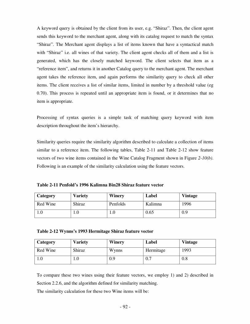
- 92 -
A keyword query is obtained by the client from its user, e.g. “Shiraz”. Then, the client agent
sends this keyword to the merchant agent, along with its catalog request to match the syntax
“Shiraz”. The Merchant agent displays a list of items known that have a syntactical match
with “Shiraz” i.e. all wines of that variety. The client agent checks all of them and a list is
generated, which has the closely matched keyword. The client selects that item as a
“reference item”, and returns it in another Catalog query to the merchant agent. The merchant
agent takes the reference item, and again performs the similarity query to check all other
items. The client receives a list of similar items, limited in number by a threshold value (eg
0.70). This process is repeated until an appropriate item is found, or it determines that no
item is appropriate.
Processing of syntax queries is a simple task of matching query keyword with item
description throughout the item’s hierarchy.
Similarity queries require the similarity algorithm described to calculate a collection of items
similar to a reference item. The following tables, Table 2-11 and Table 2-12 show feature
vectors of two wine items contained in the Wine Catalog Fragment shown in Figure 2-10(b).
Following is an example of the similarity calculation using the feature vectors.
Table 2-11 Penfold’s 1996 Kalimna Bin28 Shiraz feature vector
Category Variety Winery Label Vintage
Red Wine Shiraz Penfolds Kalimna 1996
1.0 1.0 1.0 0.65 0.9
Table 2-12 Wynns’s 1993 Hermitage Shiraz feature vector
Category Variety Winery Label Vintage
Red Wine Shiraz Wynns Hermitage 1993
1.0 1.0 0.9 0.7 0.8
To compare these two wines using their feature vectors, we employ 1) and 2) described in
Section 2.2.6, and the algorithm defined for similarity matching.
The similarity calculation for these two Wine items will be:
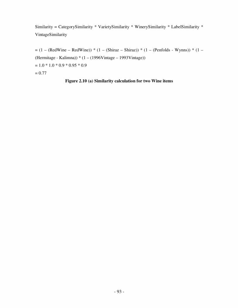
- 93 -
Similarity = CategorySimilarity * VarietySimilarity * WinerySimilarity * LabelSimilarity *
VintageSimilarity
= (1 – (RedWine – RedWine)) * (1 – (Shiraz – Shiraz)) * (1 – (Penfolds - Wynns)) * (1 –
(Hermitage - Kalimna)) * (1 – (1996Vintage – 1993Vintage))
= 1.0 * 1.0 * 0.9 * 0.95 * 0.9
= 0.77
Figure 2.10 (a) Similarity calculation for two Wine items
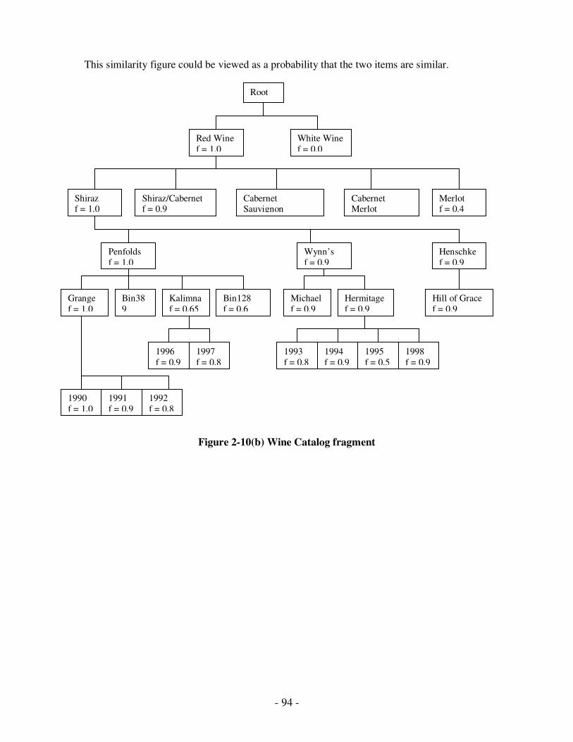
- 94 -
This similarity figure could be viewed as a probability that the two items are similar.
Figure 2-10(b) Wine Catalog fragment
Root
Red Wine
f = 1.0
White Wine
f = 0.0
Shiraz f = 1.0
Shiraz/Cabernet f = 0.9
Cabernet Sauvignon
Cabernet Merlot
Merlot f = 0.4
Penfolds
f = 1.0
Wynn’s
f = 0.9
Henschke
f = 0.9
Grange
f = 1.0
Bin128
f = 0.6
Bin38
9
Kalimna
f = 0.65
Michael
f = 0.9
Hermitage
f = 0.9
Hill of Grace
f = 0.9
1996
f = 0.9
1997
f = 0.8
1993
f = 0.8
1994
f = 0.9
1995
f = 0.5
1998
f = 0.9
1990
f = 1.0
1991
f = 0.9
1992
f = 0.8
- 95 -
2.3.5 Merchant Protocols
We use three different merchant protocols:
� Shopfront protocol
This is a simple protocol use to browse for a specific item when buying it at the merchant’s
advertised price. The State Transition Diagram for this protocol is shown in Figure 2.11. The
FSM message table for this protocol is detailed in
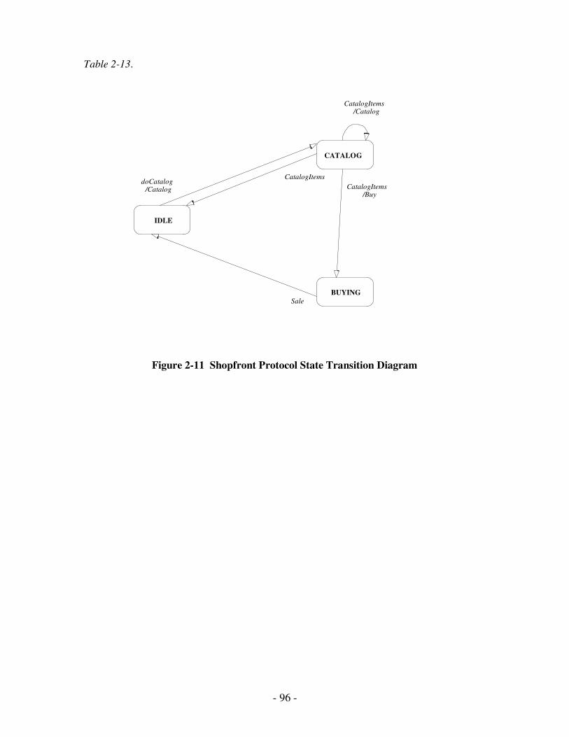
- 96 -
Table 2-13.
Figure 2-11 Shopfront Protocol State Transition Diagram
CATALOG
BUYING
IDLE
/Catalog CatalogItems
/Buy CatalogItems
CatalogItems
/Catalog doCatalog
Sale
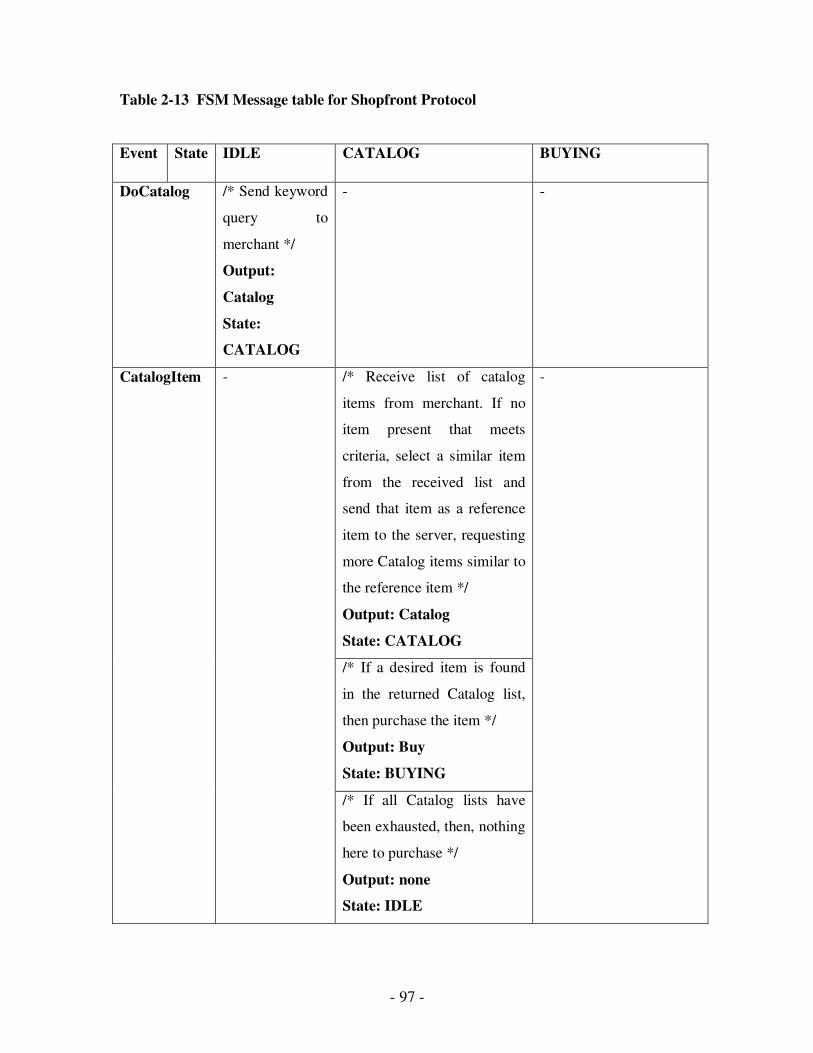
- 97 -
Table 2-13 FSM Message table for Shopfront Protocol
Event State IDLE CATALOG BUYING
DoCatalog /* Send keyword
query to
merchant */
Output:
Catalog
State:
CATALOG
- -
/* Receive list of catalog
items from merchant. If no
item present that meets
criteria, select a similar item
from the received list and
send that item as a reference
item to the server, requesting
more Catalog items similar to
the reference item */
Output: Catalog
State: CATALOG
/* If a desired item is found
in the returned Catalog list,
then purchase the item */
Output: Buy
State: BUYING
CatalogItem -
/* If all Catalog lists have
been exhausted, then, nothing
here to purchase */
Output: none
State: IDLE
-
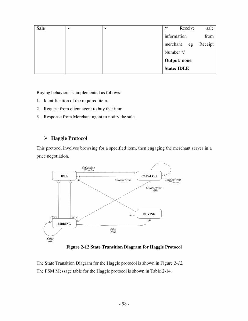
- 98 -
Sale - - /* Receive sale
information from
merchant eg Receipt
Number */
Output: none
State: IDLE
Buying behaviour is implemented as follows:
1. Identification of the required item.
2. Request from client agent to buy that item.
3. Response from Merchant agent to notify the sale.
� Haggle Protocol
This protocol involves browsing for a specified item, then engaging the merchant server in a
price negotiation.
Figure 2-12 State Transition Diagram for Haggle Protocol
The State Transition Diagram for the Haggle protocol is shown in Figure 2-12.
The FSM Message table for the Haggle protocol is shown in Table 2-14.
CATALOG
BIDDING
BUYING
IDLE
/Catalog CatalogItems
Offer Sale
/Bid Offer
/Catalog doCatalog
CatalogItems
/Buy Offer
Sale
/Bid CatalogItems
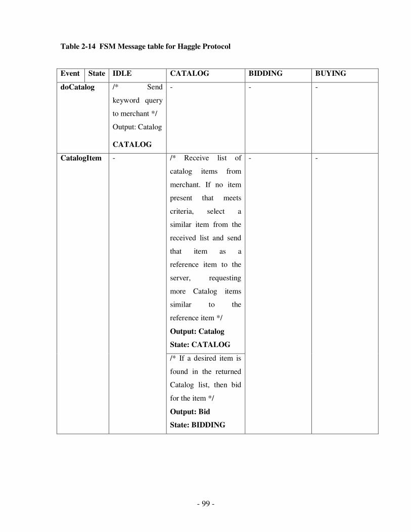
- 99 -
Table 2-14 FSM Message table for Haggle Protocol
Event State IDLE CATALOG BIDDING BUYING
doCatalog /* Send
keyword query
to merchant */
Output: Catalog
CATALOG
- - -
/* Receive list of
catalog items from
merchant. If no item
present that meets
criteria, select a
similar item from the
received list and send
that item as a
reference item to the
server, requesting
more Catalog items
similar to the
reference item */
Output: Catalog
State: CATALOG
CatalogItem -
/* If a desired item is
found in the returned
Catalog list, then bid
for the item */
Output: Bid
State: BIDDING
- -
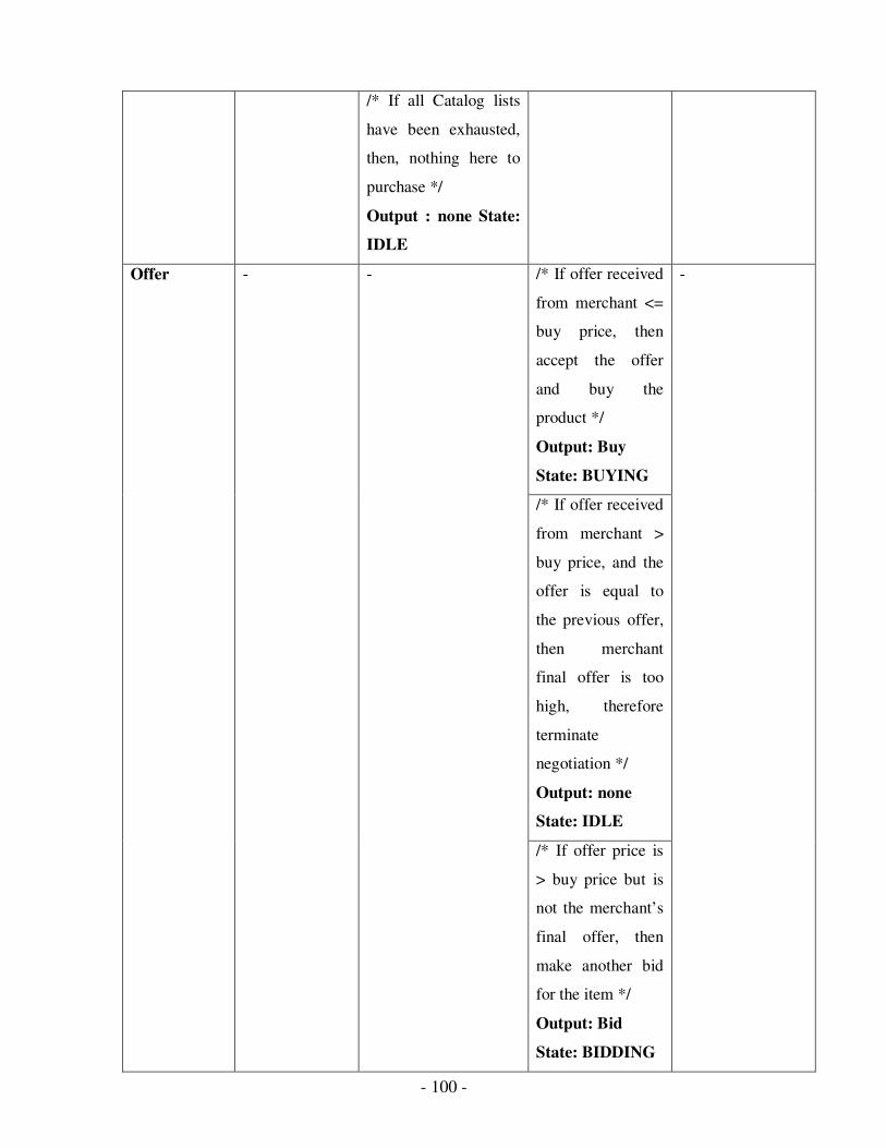
- 100 -
/* If all Catalog lists
have been exhausted,
then, nothing here to
purchase */
Output : none State:
IDLE
/* If offer received
from merchant <=
buy price, then
accept the offer
and buy the
product */
Output: Buy
State: BUYING
/* If offer received
from merchant >
buy price, and the
offer is equal to
the previous offer,
then merchant
final offer is too
high, therefore
terminate
negotiation */
Output: none
State: IDLE
Offer - -
/* If offer price is
> buy price but is
not the merchant’s
final offer, then
make another bid
for the item */
Output: Bid
State: BIDDING
-
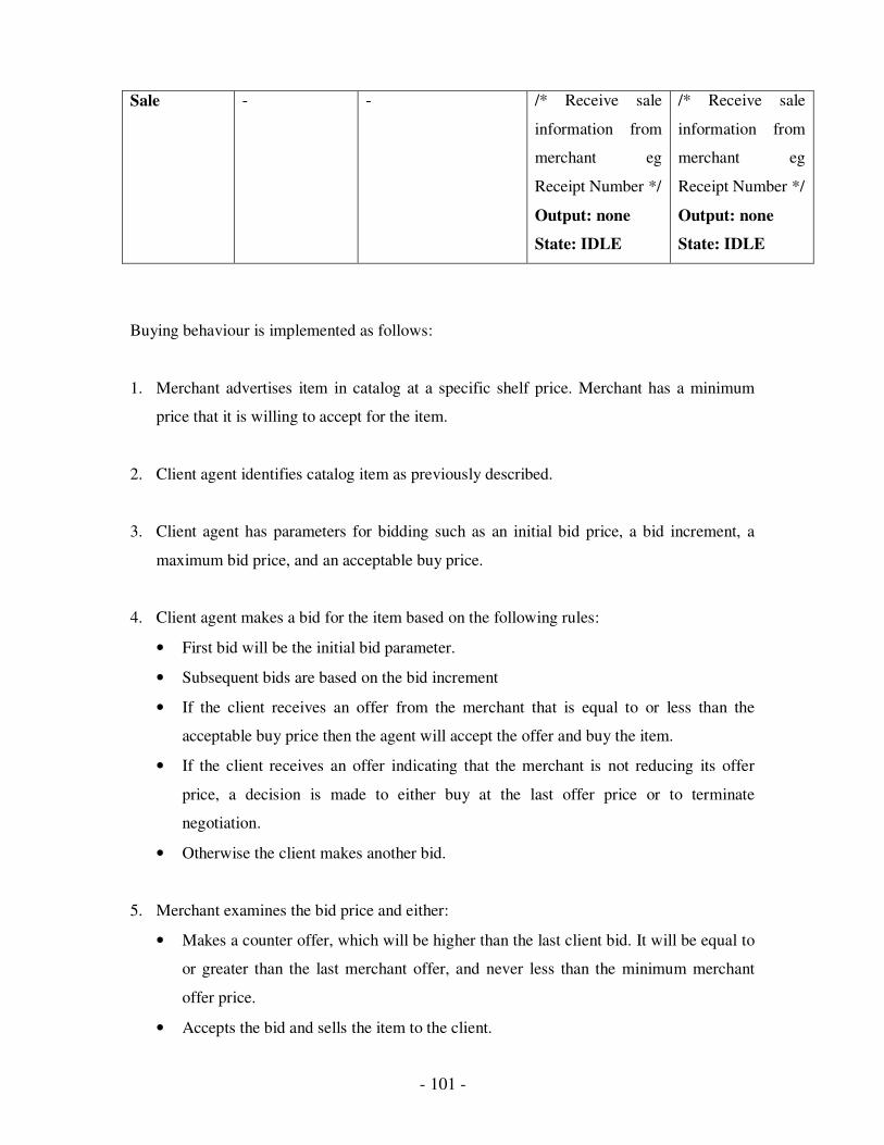
- 101 -
Sale - - /* Receive sale
information from
merchant eg
Receipt Number */
Output: none
State: IDLE
/* Receive sale
information from
merchant eg
Receipt Number */
Output: none
State: IDLE
Buying behaviour is implemented as follows:
1. Merchant advertises item in catalog at a specific shelf price. Merchant has a minimum
price that it is willing to accept for the item.
2. Client agent identifies catalog item as previously described.
3. Client agent has parameters for bidding such as an initial bid price, a bid increment, a
maximum bid price, and an acceptable buy price.
4. Client agent makes a bid for the item based on the following rules:
• First bid will be the initial bid parameter.
• Subsequent bids are based on the bid increment
• If the client receives an offer from the merchant that is equal to or less than the
acceptable buy price then the agent will accept the offer and buy the item.
• If the client receives an offer indicating that the merchant is not reducing its offer
price, a decision is made to either buy at the last offer price or to terminate
negotiation.
• Otherwise the client makes another bid.
5. Merchant examines the bid price and either:
• Makes a counter offer, which will be higher than the last client bid. It will be equal to
or greater than the last merchant offer, and never less than the minimum merchant
offer price.
• Accepts the bid and sells the item to the client.
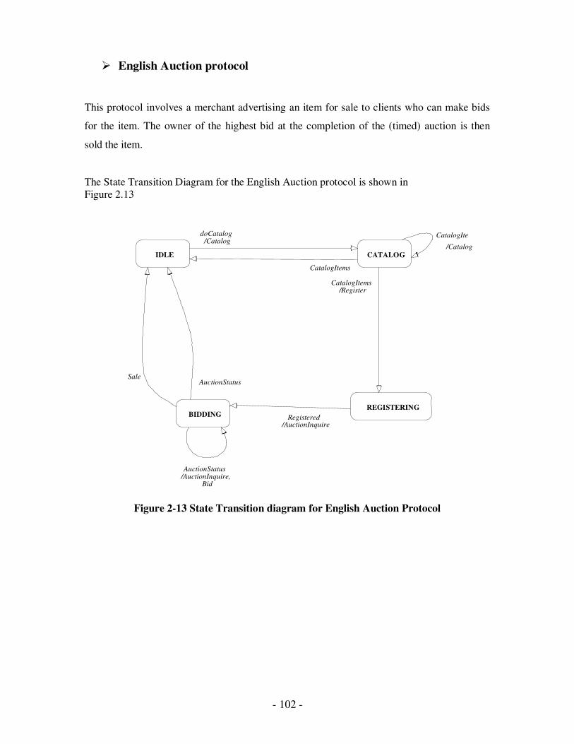
- 102 -
� English Auction protocol
This protocol involves a merchant advertising an item for sale to clients who can make bids
for the item. The owner of the highest bid at the completion of the (timed) auction is then
sold the item.
The State Transition Diagram for the English Auction protocol is shown in
Figure 2.13
Figure 2-13 State Transition diagram for English Auction Protocol
CATALOG
BIDDING REGISTERING
IDLE /Catalog
Bid /AuctionInquire, AuctionStatus
/AuctionInquire Registered
/Register CatalogItems
AuctionStatus
/Catalog doCatalog
CatalogItems
Sale
CatalogIte
ms
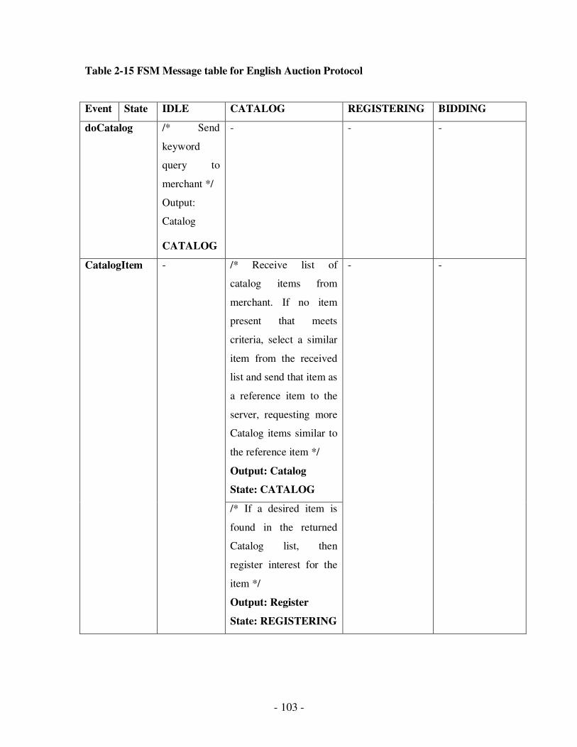
- 103 -
Table 2-15 FSM Message table for English Auction Protocol
Event State IDLE CATALOG REGISTERING BIDDING
doCatalog /* Send
keyword
query to
merchant */
Output:
Catalog
CATALOG
- - -
/* Receive list of
catalog items from
merchant. If no item
present that meets
criteria, select a similar
item from the received
list and send that item as
a reference item to the
server, requesting more
Catalog items similar to
the reference item */
Output: Catalog
State: CATALOG
CatalogItem -
/* If a desired item is
found in the returned
Catalog list, then
register interest for the
item */
Output: Register
State: REGISTERING
- -
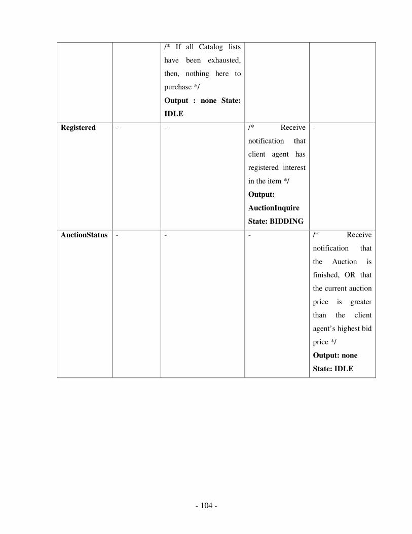
- 104 -
/* If all Catalog lists
have been exhausted,
then, nothing here to
purchase */
Output : none State:
IDLE
Registered - - /* Receive
notification that
client agent has
registered interest
in the item */
Output:
AuctionInquire
State: BIDDING
-
AuctionStatus - - - /* Receive
notification that
the Auction is
finished, OR that
the current auction
price is greater
than the client
agent’s highest bid
price */
Output: none
State: IDLE
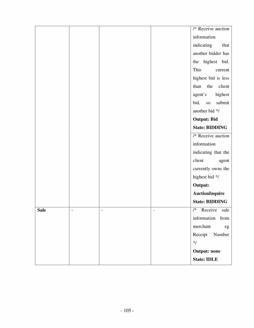
- 105 -
/* Receive auction
information
indicating that
another bidder has
the highest bid.
This current
highest bid is less
than the client
agent’s highest
bid, so submit
another bid */
Output: Bid
State: BIDDING
/* Receive auction
information
indicating that the
client agent
currently owns the
highest bid */
Output:
AuctionInquire
State: BIDDING
Sale - - - /* Receive sale
information from
merchant eg
Receipt Number
*/
Output: none
State: IDLE
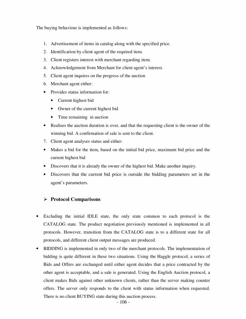
- 106 -
The buying behaviour is implemented as follows:
1. Advertisement of items in catalog along with the specified price.
2. Identification by client agent of the required item.
3. Client registers interest with merchant regarding item.
4. Acknowledgement from Merchant for client agent’s interest.
5. Client agent inquires on the progress of the auction
6. Merchant agent either:
• Provides status information for:
• Current highest bid
• Owner of the current highest bid
• Time remaining in auction
• Realises the auction duration is over, and that the requesting client is the owner of the
winning bid. A confirmation of sale is sent to the client.
7. Client agent analyses status and either:
• Makes a bid for the item, based on the initial bid price, maximum bid price and the
current highest bid
• Discovers that it is already the owner of the highest bid. Make another inquiry.
• Discovers that the current bid price is outside the bidding parameters set in the
agent’s parameters.
� Protocol Comparisons
• Excluding the initial IDLE state, the only state common to each protocol is the
CATALOG state. The product negotiation previously mentioned is implemented in all
protocols. However, transition from the CATALOG state is to a different state for all
protocols, and different client output messages are produced.
• BIDDING is implemented in only two of the merchant protocols. The implementation of
bidding is quite different in these two situations. Using the Haggle protocol, a series of
Bids and Offers are exchanged until either agent decides that a price contracted by the
other agent is acceptable, and a sale is generated. Using the English Auction protocol, a
client makes Bids against other unknown clients, rather than the server making counter
offers. The server only responds to the client with status information when requested.
There is no client BUYING state during this auction process.

- 107 -
• BUYING is implemented in only two of the merchant protocols. Each of these protocols
has a different transition to BUYING. The Shopfront protocol chooses to buy after a
catalog search, and for the Haggle protocol, BUYING is reached after a series of Bid and
Offer exchanges.
• Of the ten vocabulary items available, four are used in the Shopfront protocol, six are
used in the Haggle protocol and eight are used in the English Auction protocol.
These comparisons show that the vocabulary primitives defined earlier can be used
independently to compose different valid protocol definitions. For example, with only a
fundamental understanding of what a Bid is, BIDDING can be implemented in different
ways, or Sale can be implemented in different protocols using different state transitions.
2.3.6 Client agent
A client agent is implemented using Java SDK 1.3 and JAXP 1.1 for XML parsing.
2.3.7 Client parameters
Client agent used the following parameters during product brokering and item purchase.
They are retrieved from a client agent properties file.
Table 2-16 Client Agent parameters
Parameter Example
Value
Description
item Shiraz A simple keyword query to initiate product brokering.
buy.price 230 Maximum price user is willing to pay for an item.
bid.start 180 For bidding protocols, the amount the agent should make
for the first bid.
bid.increment 10 The amount by which successive bids increment.
merchant yallara:28038 URL of merchant(s)
behaviour value Mode used to find a product. Either “value” or “cheapest”.
Explained further in the product brokering.
search.high 1.10 For product brokering, the upper price which the agent
should consider when searching for items. In this example,
the agent should consider items up to 1.1 * 230, or $253.

- 108 -
When some protocols are used, this might be a starting
point for price negotiation, therefore such an item may
subsequently be offered at or below the agent’s maximum
price.
search.low 0.90 The low price bound which the agent should consider when
searching for items. Using search.high and search.low
parameters, the user essentially has a price band for
choosing items.
similarity.thre
shold
0.75 When selecting an item from a similarity match, this is the
lowest acceptable similarity match for a chosen item.
spy true This initiates a GUI Observer on the client agent showing
the input events, the output messages and the state changes.
Samples of this GUI are shown in some of the following
test examples.
2.3.8 Vocabulary Implementation
The client agent has a record of all the vocabulary items previously mentioned.
Implementation of each of these vocabulary items is done independently as either an
expected input event, or an output message from the state machine. Implementation of each
of these vocabulary phrases is done in a fundamental way, so that no vocabulary phrase
implementation needs to know anything about other phrases. For example, a simple
implementation of the fundamental bid operation is listed in Figure 2.18.
private ProtocolMessage doBid() {
Bid bid = new Bid();
bidPrice += bidIncrement;
if (bidPrice > buyPrice)
bidPrice = buyPrice;
bid.setItem(item);
bid.setItemId(itemId);
bid.setPrice(bidPrice);
bid.setQuantity(quantity);
bid.setBidderId(bidderId);
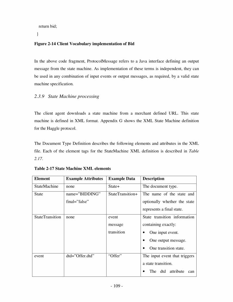
- 109 -
return bid;
}
Figure 2-14 Client Vocabulary implementation of Bid
In the above code fragment, ProtocolMessage refers to a Java interface defining an output
message from the state machine. As implementation of these terms is independent, they can
be used in any combination of input events or output messages, as required, by a valid state
machine specification.
2.3.9 State Machine processing
The client agent downloads a state machine from a merchant defined URL. This state
machine is defined in XML format. Appendix G shows the XML State Machine definition
for the Haggle protocol.
The Document Type Definition describes the following elements and attributes in the XML
file. Each of the element tags for the StateMachine XML definition is described in Table
2.17.
Table 2-17 State Machine XML elements
Element Example Attributes Example Data Description
StateMachine none State+ The document type.
State name=”BIDDING”
final=”false”
StateTransition+ The name of the state and
optionally whether the state
represents a final state.
StateTransition none event
message
transition
State transition information
containing exactly:
• One input event.
• One output message.
• One transition state.
event dtd=”Offer.dtd” “Offer” The input event that triggers
a state transition.
• The dtd attribute can
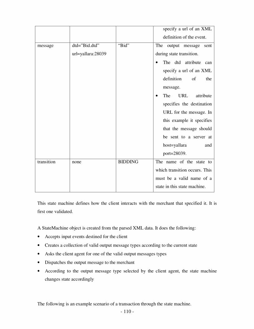
- 110 -
specify a url of an XML
definition of the event.
message dtd=”Bid.dtd”
url=yallara:28039
“Bid” The output message sent
during state transition.
• The dtd attribute can
specify a url of an XML
definition of the
message.
• The URL attribute
specifies the destination
URL for the message. In
this example it specifies
that the message should
be sent to a server at
host=yallara and
port=28039.
transition none BIDDING The name of the state to
which transition occurs. This
must be a valid name of a
state in this state machine.
This state machine defines how the client interacts with the merchant that specified it. It is
first one validated.
A StateMachine object is created from the parsed XML data. It does the following:
• Accepts input events destined for the client
• Creates a collection of valid output message types according to the current state
• Asks the client agent for one of the valid output messages types
• Dispatches the output message to the merchant
• According to the output message type selected by the client agent, the state machine
changes state accordingly
The following is an example scenario of a transaction through the state machine.
- 111 -
The initial state of the state machine is the first state encountered, in this case, IDLE.
As client/server transactions are initiated by the client, the state machine simulates a “Void”
input message to initiate processing. Defined transitions from IDLE are only to CATALOG
state, with the output of a Catalog message to the specified URL. This is the first message
sent by the client agent to the merchant server.
Now in the CATALOG state, the state machine will only expect a CatalogItems input event
from the merchant. This part of the state machine involves the negotiation between the client
and the merchant regarding the selected product. Input events for this negotiation can lead to
any of the three following transitions:
• BIDDING – If a satisfactory item is found for purchase.
• CATALOG – If further catalog item negotiation is to be performed.
• IDLE – If no satisfactory item is found for purchase.
Transitions will depend on the items returned from the initial user-supplied syntax query, and
subsequent reference item queries.
As an example, assume that a suitable item is found in the merchant’s CatalogItems. The
client will return a Bid message via the state machine to the merchant and transition is made
to a BIDDING state.
Now in the BIDDING state, the state machine is expecting either an “Offer” or a “Sale”
event only. If an Offer event is received from the merchant, the state machine will request the
client agent to return a “Buy” or “Bid” message back to the merchant. The agent could also
choose the “Void” message option, indicating that no response is required to the merchant.
This process of Bid and Offers can cycle. It is important to prevent a livelock when cycles of
messages are allowed. The vocabulary definitions of Bid and Offer cater for this in their
specification. When successive Bids or Offers have the same monetary value, it can be
assumed that no further Bids/Offers will be changed, effectively meaning that it is the final
Bid/Offer. Then, the cycle will cease. Eventually, either a “Void” message or a “Buy”
message would be sent to the state machine from the agent.
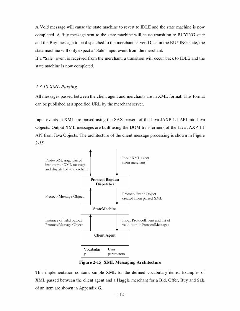
- 112 -
A Void message will cause the state machine to revert to IDLE and the state machine is now
completed. A Buy message sent to the state machine will cause transition to BUYING state
and the Buy message to be dispatched to the merchant server. Once in the BUYING state, the
state machine will only expect a “Sale” input event from the merchant.
If a “Sale” event is received from the merchant, a transition will occur back to IDLE and the
state machine is now completed.
2.3.10 XML Parsing
All messages passed between the client agent and merchants are in XML format. This format
can be published at a specified URL by the merchant server.
Input events in XML are parsed using the SAX parsers of the Java JAXP 1.1 API into Java
Objects. Output XML messages are built using the DOM transformers of the Java JAXP 1.1
API from Java Objects. The architecture of the client message processing is shown in Figure
2-15.
Figure 2-15 XML Messaging Architecture
This implementation contains simple XML for the defined vocabulary items. Examples of
XML passed between the client agent and a Haggle merchant for a Bid, Offer, Buy and Sale
of an item are shown in Appendix G.
Protocol Request Dispatcher
StateMachine
Client Agent
Vocabular
y
User parameters
Input XML event from merchant
ProtocolEvent Object created from parsed XML
Input ProtocolEvent and list of valid output ProtocolMessages
Instance of valid output ProtocolMessage Object
ProtocolMessage Object
ProtocolMessage parsed into output XML message and dispatched to merchant
- 113 -
2.4 Testing
Testing is the last step, and includes the following areas:
� State Machine correctness. This section mainly deals with the correctness of the state
machine. Testing ensures that valid state machine definitions can be successfully
downloaded and validated, and that invalid state machine definitions can be detected by a
client agent and discarded.
� Product Brokering. The common product brokering mechanism involving syntax matches
and similarity matches can successfully broker a product for the client agent. This
exchange is initiated from user parameters given to the client agent.
� Individual protocol testing. These tests are designed to ensure that every state and
transition in any individual state machine definition can be successfully invoked, and
client state machines can successfully traverse from initial state to all final states.
� Merchant Brokering. When a client agent is negotiating with multiple merchant servers,
the client agent must be able to decide between merchant agents based on the product
brokering results from each agent.
2.4.1 State Machine Correctness
Three valid State Machines were defined using XML for the Shopfront, Haggle and
EnglishAuction protocols. All of these client protocols successfully validate.
Each state machine specification is defined as the file StateMachine.xml in the root directory
used for implementation of each merchant server. This file is accessed either via a well-
known TCP port used by each merchant, or via a known URL for access via JAVA Servlets.
Appendix G shows an XML fragment of an invalid state machine specification (1) used to
test the state machine validation process. This state machine is an invalid version of the
Haggle protocol. The transition form IDLE to CATALOG has mistakenly been made to
BUYING instead.

- 114 -
This error means that the CATALOG state cannot be reached from any other state. Forward
reachability analysis of the StateMachine validation will fail during state machine creation
with the error:
State CATALOG not reachable from initial state
Figure 2-16 Forward Reachability error in Client state machine
Figure 2-16 shows this invalid client state machine example.
Similarly, the following fragment of XML defines an invalid state machine for the Haggle
protocol. The transition from BUYING to IDLE has mistakenly been made to BUYING.
This does not provide any path from BUYING to any final state. Backwards reachability will
fail on the BUYING state. Backward reachability analysis of the StateMachine validation
will fail during state machine creation with the error:
State BUYING cannot reach a final state
CATALOG
BIDDING
BUYING
IDLE
/Catalog CatalogItems
Offer Sale
/Bid Offer
/Catalog doCatalog
CatalogItems
/Buy Offer
Sale
/Bid CatalogItems
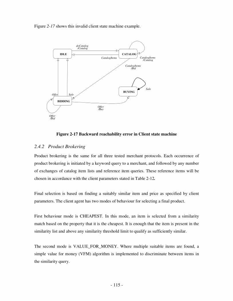
- 115 -
Figure 2-17 shows this invalid client state machine example.
Figure 2-17 Backward reachability error in Client state machine
2.4.2 Product Brokering
Product brokering is the same for all three tested merchant protocols. Each occurrence of
product brokering is initiated by a keyword query to a merchant, and followed by any number
of exchanges of catalog item lists and reference item queries. These reference items will be
chosen in accordance with the client parameters stated in Table 2-12.
Final selection is based on finding a suitably similar item and price as specified by client
parameters. The client agent has two modes of behaviour for selecting a final product.
First behaviour mode is CHEAPEST. In this mode, an item is selected from a similarity
match based on the property that it is the cheapest. It is enough that the item is present in the
similarity list and above any similarity threshold limit to qualify as sufficiently similar.
The second mode is VALUE_FOR_MONEY. Where multiple suitable items are found, a
simple value for money (VFM) algorithm is implemented to discriminate between items in
the similarity query.
CATALOG
BIDDING
BUYING
IDLE
/Catalog CatalogItems
Offer Sale
/Bid Offer
/Catalog doCatalog
CatalogItems
/Buy Offer
Sale
/Bid CatalogItems
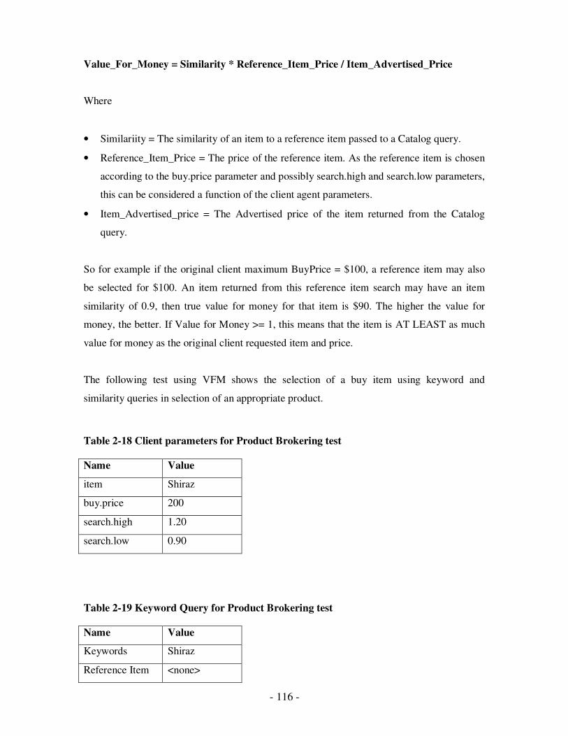
- 116 -
Value_For_Money = Similarity * Reference_Item_Price / Item_Advertised_Price
Where
• Similariity = The similarity of an item to a reference item passed to a Catalog query.
• Reference_Item_Price = The price of the reference item. As the reference item is chosen
according to the buy.price parameter and possibly search.high and search.low parameters,
this can be considered a function of the client agent parameters.
• Item_Advertised_price = The Advertised price of the item returned from the Catalog
query.
So for example if the original client maximum BuyPrice = $100, a reference item may also
be selected for $100. An item returned from this reference item search may have an item
similarity of 0.9, then true value for money for that item is $90. The higher the value for
money, the better. If Value for Money >= 1, this means that the item is AT LEAST as much
value for money as the original client requested item and price.
The following test using VFM shows the selection of a buy item using keyword and
similarity queries in selection of an appropriate product.
Table 2-18 Client parameters for Product Brokering test
Name Value
item Shiraz
buy.price 200
search.high 1.20
search.low 0.90
Table 2-19 Keyword Query for Product Brokering test
Name Value
Keywords Shiraz
Reference Item <none>
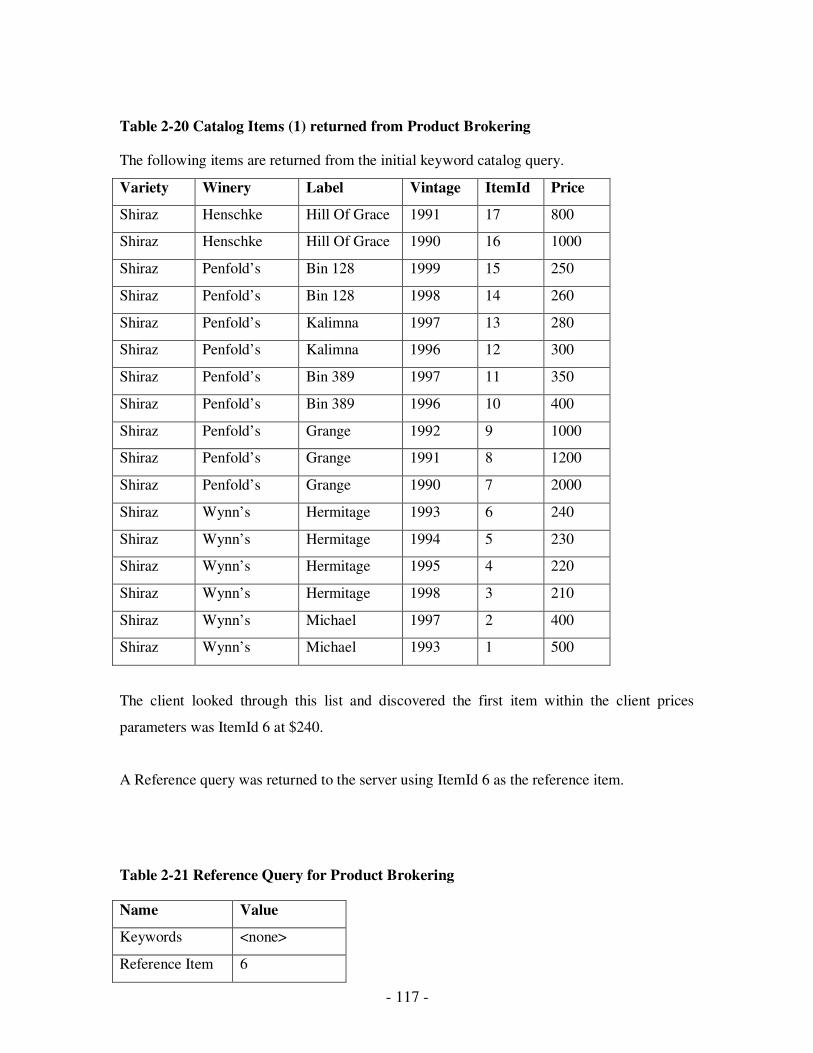
- 117 -
Table 2-20 Catalog Items (1) returned from Product Brokering
The following items are returned from the initial keyword catalog query.
Variety Winery Label Vintage ItemId Price
Shiraz Henschke Hill Of Grace 1991 17 800
Shiraz Henschke Hill Of Grace 1990 16 1000
Shiraz Penfold’s Bin 128 1999 15 250
Shiraz Penfold’s Bin 128 1998 14 260
Shiraz Penfold’s Kalimna 1997 13 280
Shiraz Penfold’s Kalimna 1996 12 300
Shiraz Penfold’s Bin 389 1997 11 350
Shiraz Penfold’s Bin 389 1996 10 400
Shiraz Penfold’s Grange 1992 9 1000
Shiraz Penfold’s Grange 1991 8 1200
Shiraz Penfold’s Grange 1990 7 2000
Shiraz Wynn’s Hermitage 1993 6 240
Shiraz Wynn’s Hermitage 1994 5 230
Shiraz Wynn’s Hermitage 1995 4 220
Shiraz Wynn’s Hermitage 1998 3 210
Shiraz Wynn’s Michael 1997 2 400
Shiraz Wynn’s Michael 1993 1 500
The client looked through this list and discovered the first item within the client prices
parameters was ItemId 6 at $240.
A Reference query was returned to the server using ItemId 6 as the reference item.
Table 2-21 Reference Query for Product Brokering
Name Value
Keywords <none>
Reference Item 6
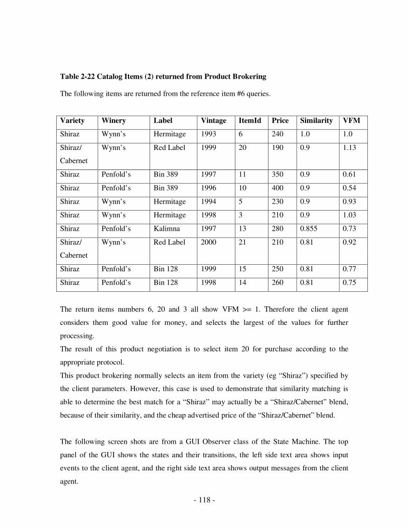
- 118 -
Table 2-22 Catalog Items (2) returned from Product Brokering
The following items are returned from the reference item #6 queries.
Variety Winery Label Vintage ItemId Price Similarity VFM
Shiraz Wynn’s Hermitage 1993 6 240 1.0 1.0
Shiraz/
Cabernet
Wynn’s Red Label 1999 20 190 0.9 1.13
Shiraz Penfold’s Bin 389 1997 11 350 0.9 0.61
Shiraz Penfold’s Bin 389 1996 10 400 0.9 0.54
Shiraz Wynn’s Hermitage 1994 5 230 0.9 0.93
Shiraz Wynn’s Hermitage 1998 3 210 0.9 1.03
Shiraz Penfold’s Kalimna 1997 13 280 0.855 0.73
Shiraz/
Cabernet
Wynn’s Red Label 2000 21 210 0.81 0.92
Shiraz Penfold’s Bin 128 1999 15 250 0.81 0.77
Shiraz Penfold’s Bin 128 1998 14 260 0.81 0.75
The return items numbers 6, 20 and 3 all show VFM >= 1. Therefore the client agent
considers them good value for money, and selects the largest of the values for further
processing.
The result of this product negotiation is to select item 20 for purchase according to the
appropriate protocol.
This product brokering normally selects an item from the variety (eg “Shiraz”) specified by
the client parameters. However, this case is used to demonstrate that similarity matching is
able to determine the best match for a “Shiraz” may actually be a “Shiraz/Cabernet” blend,
because of their similarity, and the cheap advertised price of the “Shiraz/Cabernet” blend.
The following screen shots are from a GUI Observer class of the State Machine. The top
panel of the GUI shows the states and their transitions, the left side text area shows input
events to the client agent, and the right side text area shows output messages from the client
agent.
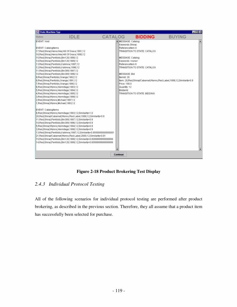
- 119 -
Figure 2-18 Product Brokering Test Display
2.4.3 Individual Protocol Testing
All of the following scenarios for individual protocol testing are performed after product
brokering, as described in the previous section. Therefore, they all assume that a product item
has successfully been selected for purchase.

- 120 -
• Shopfront Protocol scenario
Table 2-23 Shopfront Protocol Test Scenarios
Scenario Description Message sequence and
STATE transition
Client parameters and
result
Successful Buy Agent buys item from
merchant at advertised price.
Send Buy → BUYING
Recv Sale → IDLE
item=Cab/Sauv
buy.price=250
Client decides to buy identical
item at cheaper price of $240
{VFM}
Figure 2-19 Shopfront Buy Scenario Test Display

- 121 -
Haggle Protocol scenarios
Table 2-24 Haggle Protocol Test Scenarios
Scenario Description Message sequence and
STATE transition
Client Parameters and
result
Successful
Bid
Client agent successfully
negotiates a merchant’s
price down. Negotiation
occurs over multiple
Bid/Offer cycles. Client
decides to accept a merchant
offer. Buy message sent to
server and Sale received in
response.
Cycle of: {
Send Bid → BIDDING
Recv Offer → BIDDING}
Then:
Send Buy → BUYING
Recv Sale → IDLE
item=Shiraz
initial.bid=180
bid.increment=10
buy.price=230
search.high=1.2
search.low=0.9
sim.threshold=0.75
Item is purchased after price
negotiation for $225
ReferenceItem=15
BuyItem=14
Successful
Bid
Client agent successfully
negotiates a merchant’s
price down. Negotiation
occurs over multiple
Bid/Offer cycles. Merchant
accepts one of the client’s
Bid prices and immediately
sends a Sale message
Cycle of: {
Send Bid → BIDDING
Recv Offer → BIDDING}
Then:
Recv Sale → IDLE
item=Shiraz
initial.bid=280
buy.price=330
bid.increment=10
search.high = 1.2
search.low = 0.9
sim.threshold=0.75
ReferenceItem=12
BuyItem=3
Item is purchased after
negotiation for $280
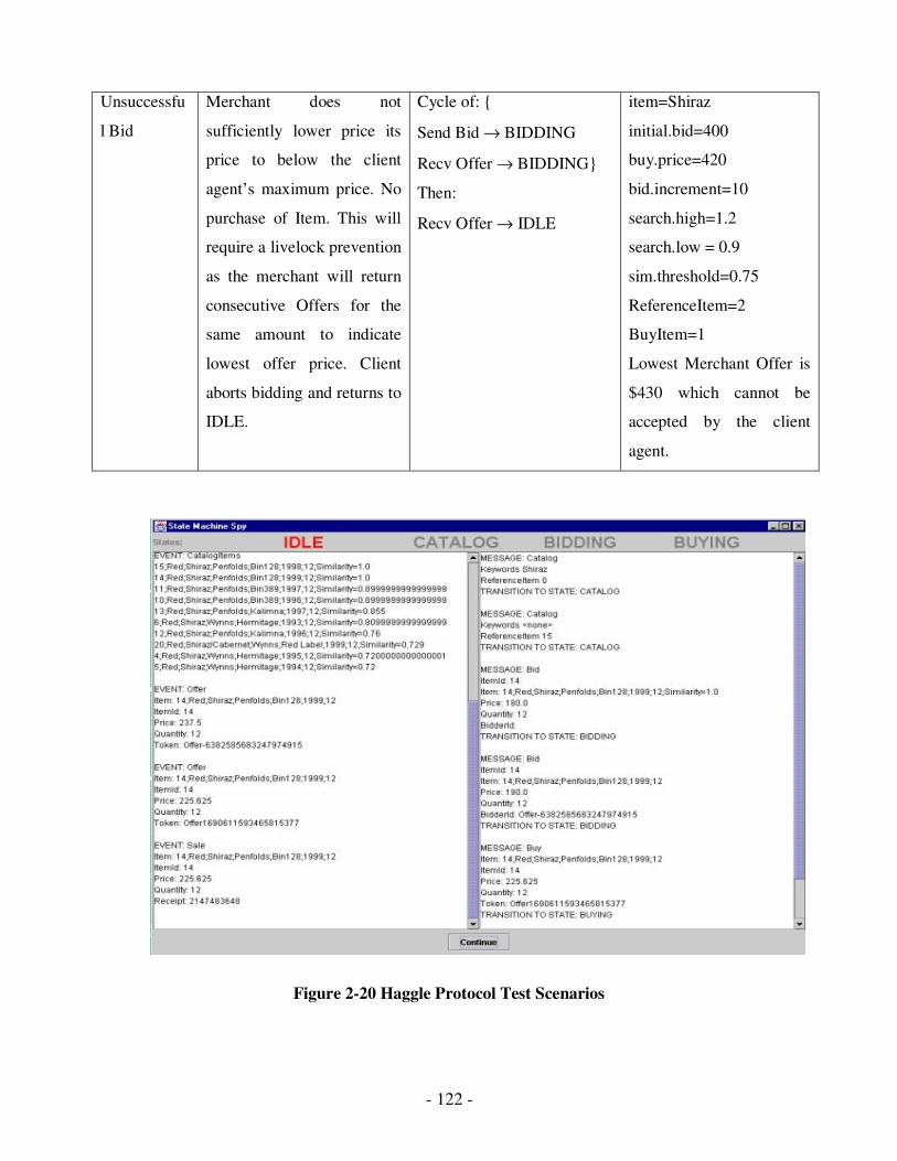
- 122 -
Unsuccessfu
l Bid
Merchant does not
sufficiently lower price its
price to below the client
agent’s maximum price. No
purchase of Item. This will
require a livelock prevention
as the merchant will return
consecutive Offers for the
same amount to indicate
lowest offer price. Client
aborts bidding and returns to
IDLE.
Cycle of: {
Send Bid → BIDDING
Recv Offer → BIDDING}
Then:
Recv Offer → IDLE
item=Shiraz
initial.bid=400
buy.price=420
bid.increment=10
search.high=1.2
search.low = 0.9
sim.threshold=0.75
ReferenceItem=2
BuyItem=1
Lowest Merchant Offer is
$430 which cannot be
accepted by the client
agent.
Figure 2-20 Haggle Protocol Test Scenarios
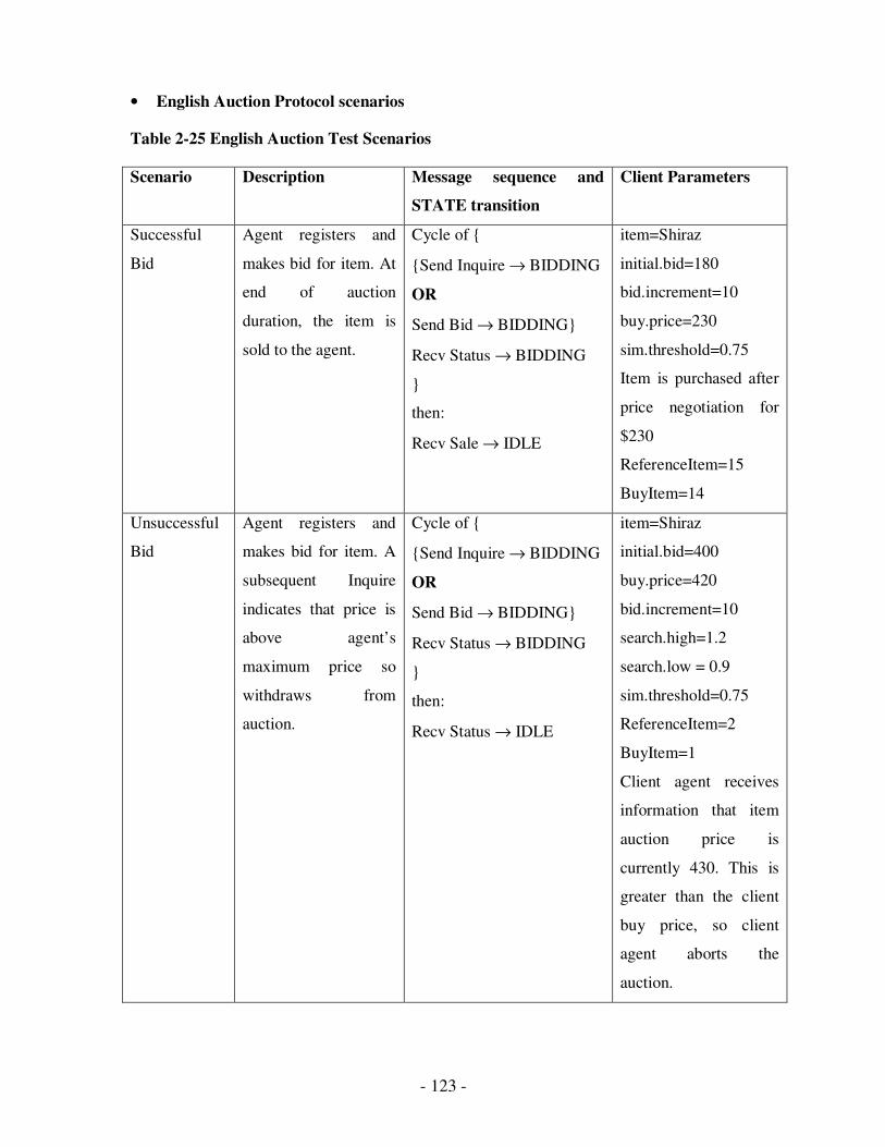
- 123 -
• English Auction Protocol scenarios
Table 2-25 English Auction Test Scenarios
Scenario Description Message sequence and
STATE transition
Client Parameters
Successful
Bid
Agent registers and
makes bid for item. At
end of auction
duration, the item is
sold to the agent.
Cycle of {
{Send Inquire → BIDDING
OR
Send Bid → BIDDING}
Recv Status → BIDDING
}
then:
Recv Sale → IDLE
item=Shiraz
initial.bid=180
bid.increment=10
buy.price=230
sim.threshold=0.75
Item is purchased after
price negotiation for
$230
ReferenceItem=15
BuyItem=14
Unsuccessful
Bid
Agent registers and
makes bid for item. A
subsequent Inquire
indicates that price is
above agent’s
maximum price so
withdraws from
auction.
Cycle of {
{Send Inquire → BIDDING
OR
Send Bid → BIDDING}
Recv Status → BIDDING
}
then:
Recv Status → IDLE
item=Shiraz
initial.bid=400
buy.price=420
bid.increment=10
search.high=1.2
search.low = 0.9
sim.threshold=0.75
ReferenceItem=2
BuyItem=1
Client agent receives
information that item
auction price is
currently 430. This is
greater than the client
buy price, so client
agent aborts the
auction.
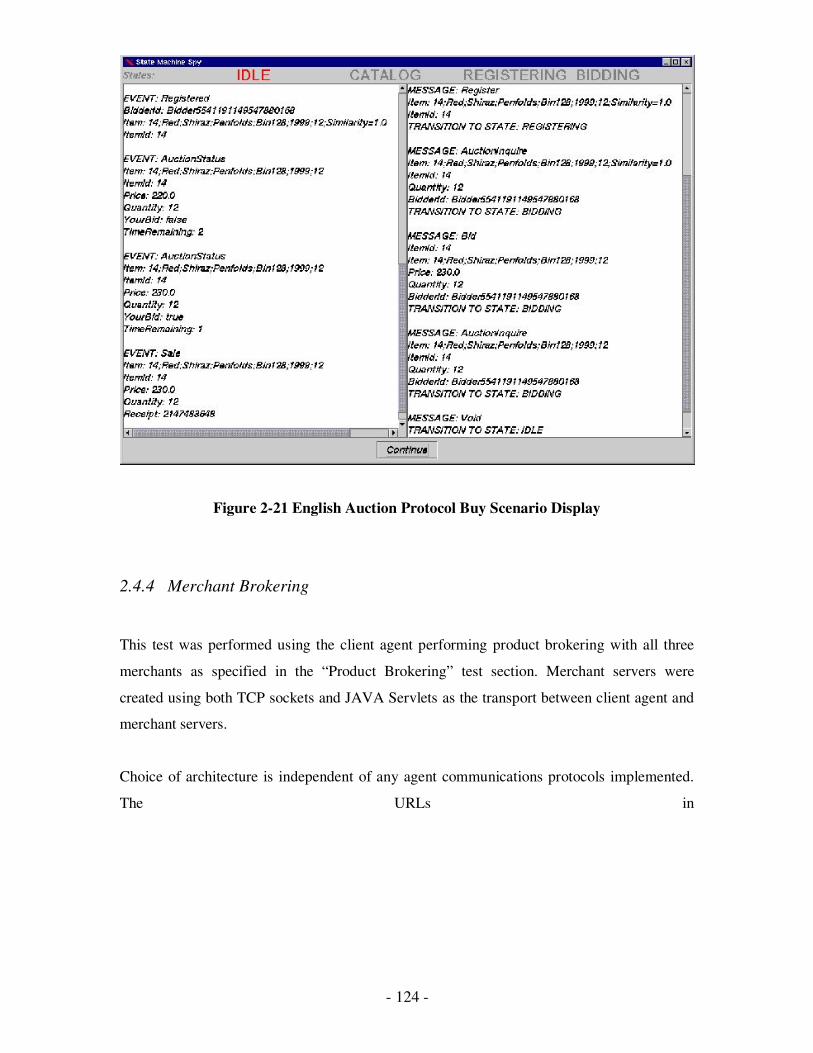
- 124 -
Figure 2-21 English Auction Protocol Buy Scenario Display
2.4.4 Merchant Brokering
This test was performed using the client agent performing product brokering with all three
merchants as specified in the “Product Brokering” test section. Merchant servers were
created using both TCP sockets and JAVA Servlets as the transport between client agent and
merchant servers.
Choice of architecture is independent of any agent communications protocols implemented.
The URLs in

- 125 -
Table were used on UNIX and Windows 95 platforms respectively.
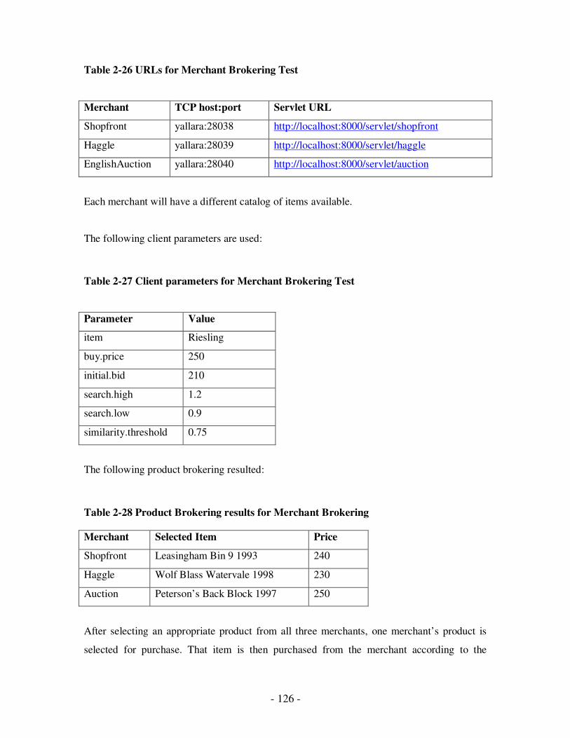
- 126 -
Table 2-26 URLs for Merchant Brokering Test
Merchant TCP host:port Servlet URL
Shopfront yallara:28038 http://localhost:8000/servlet/shopfront
Haggle yallara:28039 http://localhost:8000/servlet/haggle
EnglishAuction yallara:28040 http://localhost:8000/servlet/auction
Each merchant will have a different catalog of items available.
The following client parameters are used:
Table 2-27 Client parameters for Merchant Brokering Test
Parameter Value
item Riesling
buy.price 250
initial.bid 210
search.high 1.2
search.low 0.9
similarity.threshold 0.75
The following product brokering resulted:
Table 2-28 Product Brokering results for Merchant Brokering
Merchant Selected Item Price
Shopfront Leasingham Bin 9 1993 240
Haggle Wolf Blass Watervale 1998 230
Auction Peterson’s Back Block 1997 250
After selecting an appropriate product from all three merchants, one merchant’s product is
selected for purchase. That item is then purchased from the merchant according to the
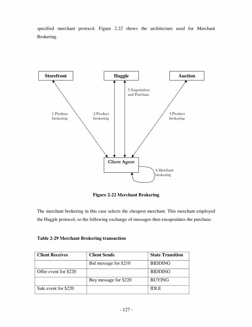
- 127 -
specified merchant protocol. Figure 2.22 shows the architecture used for Merchant
Brokering.
Figure 2-22 Merchant Brokering
The merchant brokering in this case selects the cheapest merchant. This merchant employed
the Haggle protocol, so the following exchange of messages then encapsulates the purchase.
Table 2-29 Merchant Brokering transaction
Client Receives Client Sends State Transition
Bid message for $210 BIDDING
Offer event for $220 BIDDING
Buy message for $220 BUYING
Sale event for $220 IDLE
5.Negotiation and Purchase
4.Merchant brokering
3.Product brokering
2.Product brokering
1.Product brokering
Storefront Haggle Auction
Client Agent

- 128 -
In conclusion, it is well known how important protocols are in communication, and without a
proper and error free protocol, communication is not possible at all. [27] defines a dynamic
conversation protocol is one in which the protocol interactively defines new protocols at
run time using a protocol definition and manipulation language based on a set of reserved
coordination performatives, or specifications. This chapter dealt with such a dynamic
protocol and presented an example in an auction scenario. Further, there indeed is a tight
connection between the agent’s logic and its interactions.
The next chapter deals with the various issues encountered in verifying and correcting
protocols.

- 129 -
Chapter 3: Protocol Correctness
Protocol Validation for CCSMs
Background
This chapter covers the basic concepts behind CCSMs (Communicating Complex State
Machines) and the advantages of CCSM models. Different protocol validation techniques are
used as partial and exhaustive exploration techniques. These techniques partially explore the
protocol state space for deadlock states procedure, the deadlock detection algorithm, and the
backtracking module. Implementation of the proposed algorithm is based on the XML
specification. XML parsing is used to parse information regarding the status and transitions for
XML specification, which are stored in a data structure. This section includes a discussion about
states, transitions, outgoing transitional characteristics, possible deadlock states, incoming
transitional characteristics and desired messages.
A list of classes covers a detailed description of the Java classes. The Analysis section covers the
factors analysed for validation e.g. Complexity and Comparison. The Testing section of simple,
complex and hybrid deadlock scenarios is included in Appendix B.
Sec 3.1 Related Work
According to [73], a network of communicating finite state machines (CFSM) consists of a set of
finite machines which communicate asynchronously with each other over (potentially)
unbounded FIFO channels by sending and receiving typed messages. As with any other model,
errors are a central issue during their design. As mentioned previously, in the case of CFSMs,
these errors include deadlocks, unspecified reception and unbounded communications, just to
name a few.
Various techniques have been developed to overcome these problems, the most common one is
reachability analysis, or perturbation technique. Each state is reached during the exploration of
the state space is analysed for errors after first verifying that it has not been observed in the
- 130 -
validation [74]. A major restriction on the use of reachability analysis is the state explosion
problem. The number of states that require analysis increases to a point where it is impractical to
perform analysis. [19] proposed a new strategy called PROVAT (Protocol Validation Testing),
which was based on the heuristic approach, stating that with PROVAT incorporated, the
validation tool is much more effective than blindly performing the D-search.
Research carried out by [73, 75] discovered that their technique can reduce by at least half, the
number of reachable global states that have to be searched in verifying freedom from deadlocks.
[75] tested the fair reachability technique, which was limited to a network of CFSMs with any
number of machines. Further, the latter was true for CFSMs with bounded communication, which
is the case for most practical communication protocols.
Previous works mentioned above are dated pre-2002. An overview of the recent publications on
this subject, dated post-2002, are presented next.
[84] dealt with verifying reliable web services, which consist of asynchronously communicating
peers. They used finite state machines to specify behaviour of the peers. This behaviour was
modelled similar to that of a CFSM. The “Peer Controller Pattern” was presented, which resolved
various errors occurring in web services, including protocol correctness. This approach showed
an improvement in peer-to-peer operability, which is comparable to agent-to-agent operability.
Inter-agent communication is a key component in operating systems. The idea of conformance is
equally important, and allows for substitution of agents without changes to inter-agent message
exchanges. According to [85], to ensure conformance with other others does not required any
knowledge about other services involved in the interaction. They introduced such a set of edit
operations to ensure conformance and preserve operability.
Advances in technology have seen an exponential growth in web services such as e-commerce, e-
government and data-driven web services. These services are governed by specification tools that
generate the code to carry out various functions. Verification of these codes is a major step in
protocol correctness, since it addresses the actual specification. This verification was extended by
[87] to both inter-agent communication, as well as interaction through a web interface.
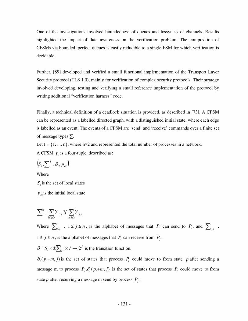
- 131 -
One of the investigations involved boundedness of queues and lossyness of channels. Results
highlighted the impact of data awareness on the verification problem. The composition of
CFSMs via bounded, perfect queues is easily reducible to a single FSM for which verification is
decidable.
Further, [89] developed and verified a small functional implementation of the Transport Layer
Security protocol (TLS 1.0), mainly for verification of complex security protocols. Their strategy
involved developing, testing and verifying a small reference implementation of the protocol by
writing additional “verification harness” code.
Finally, a technical definition of a deadlock situation is provided, as described in [73]. A CFSM
can be represented as a labelled directed graph, with a distinguished initial state, where each edge
is labelled as an event. The events of a CFSM are ‘send’ and ‘receive’ commands over a finite set
of message types ∑.
Let I = {1, ..., n}, where n≥2 and represented the total number of processes in a network.
A CFSM ip is a four-tuple, described as:
( ),,,, oiiii pS δ∑±
Where
iS is the set of local states
oip is the initial local state
∑∑ ∑≤≤
±
≤≤
∑∑=nj
ijinj
ji
1
,
1
, Υ
Where ∑ ji ,, nj ≤≤1 , is the alphabet of messages that iP can send to iP , and ∑ ij,
,
nj ≤≤1 , is the alphabet of messages that iP can receive from jP .
iS
iii IS 2: →×±× ∑δ is the transition function.
),,( jmpi −δ is the set of states that process iP could move to from state p after sending a
message m to process ),,(. jmpP ij +δ is the set of states that process iP could move to from
state p after receiving a message m send by process jP .
- 132 -
We are working on the CFSM model and there is a variety of techniques available for protocol
validation. These techniques are broadly classified into two categories, the first is based on an
exhaustive exploration, and the second is a partial exploration of the protocol state space taken as
the approach for error detection. Both the techniques have relative positive as well as negative
aspects.
3.1.1 Exhaustive Exploration Techniques
All reachable states can be verified and checked for error if a protocol has finite capacity
channels. This section will describe the techniques in which the whole state space of the protocol
is explored for error detection. These techniques can generally detect all kinds of protocol design
errors; however it may require large time and space complexities.
I. Reachability Analysis
Reachability analysis is a technique to verify communication protocols. This technique is capable
of verifying different design errors such as deadlocks, unspecified reception, non-executable
transitions and buffer overflow. These involve a systematic search of the entire state space.
Firstly, it starts from the initial global state and recursively explores all possible transitions that
lead to new global states. This search is terminated when the channels are bounded. Each new
global state is analysed for protocol design errors. For each generated global state, a check is
performed to ensure it has not already been explored. This is done by querying the data structure
that stores the already discovered global states. This data structure also provides a means for
search termination. When the successor states of all the stored states are discovered, the search is
complete.
The result is an exhaustive reachability tree that captures all details. The reachability tree drawn
for an incorrect communication system shown in Figure 3.1. Nodes of the tree indicate the global
states of the system and a ‘0’ in channel content represents an empty channel.
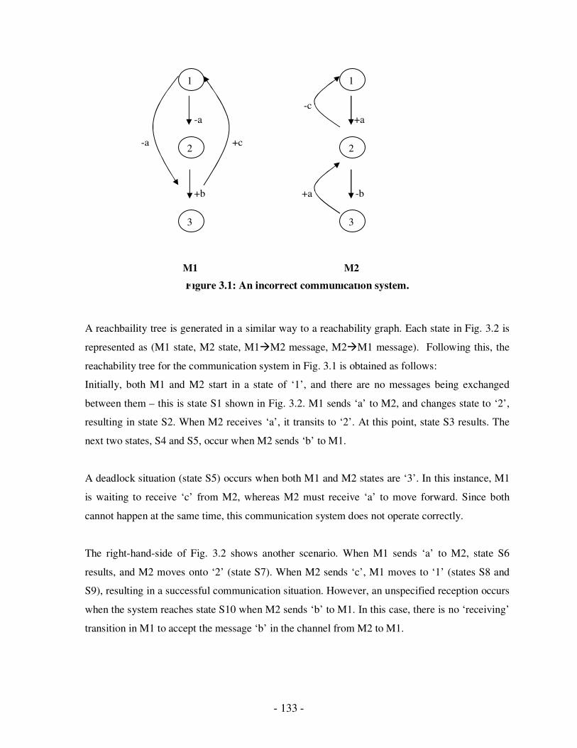
- 133 -
Figure 3.1: An incorrect communication system.
A reachbaility tree is generated in a similar way to a reachability graph. Each state in Fig. 3.2 is
represented as (M1 state, M2 state, M1�M2 message, M2�M1 message). Following this, the
reachability tree for the communication system in Fig. 3.1 is obtained as follows:
Initially, both M1 and M2 start in a state of ‘1’, and there are no messages being exchanged
between them – this is state S1 shown in Fig. 3.2. M1 sends ‘a’ to M2, and changes state to ‘2’,
resulting in state S2. When M2 receives ‘a’, it transits to ‘2’. At this point, state S3 results. The
next two states, S4 and S5, occur when M2 sends ‘b’ to M1.
A deadlock situation (state S5) occurs when both M1 and M2 states are ‘3’. In this instance, M1
is waiting to receive ‘c’ from M2, whereas M2 must receive ‘a’ to move forward. Since both
cannot happen at the same time, this communication system does not operate correctly.
The right-hand-side of Fig. 3.2 shows another scenario. When M1 sends ‘a’ to M2, state S6
results, and M2 moves onto ‘2’ (state S7). When M2 sends ‘c’, M1 moves to ‘1’ (states S8 and
S9), resulting in a successful communication situation. However, an unspecified reception occurs
when the system reaches state S10 when M2 sends ‘b’ to M1. In this case, there is no ‘receiving’
transition in M1 to accept the message ‘b’ in the channel from M2 to M1.
1
2
3
2
3
1
-a
+a
-c
+a
-b
-a
+c
+b
M1 M2
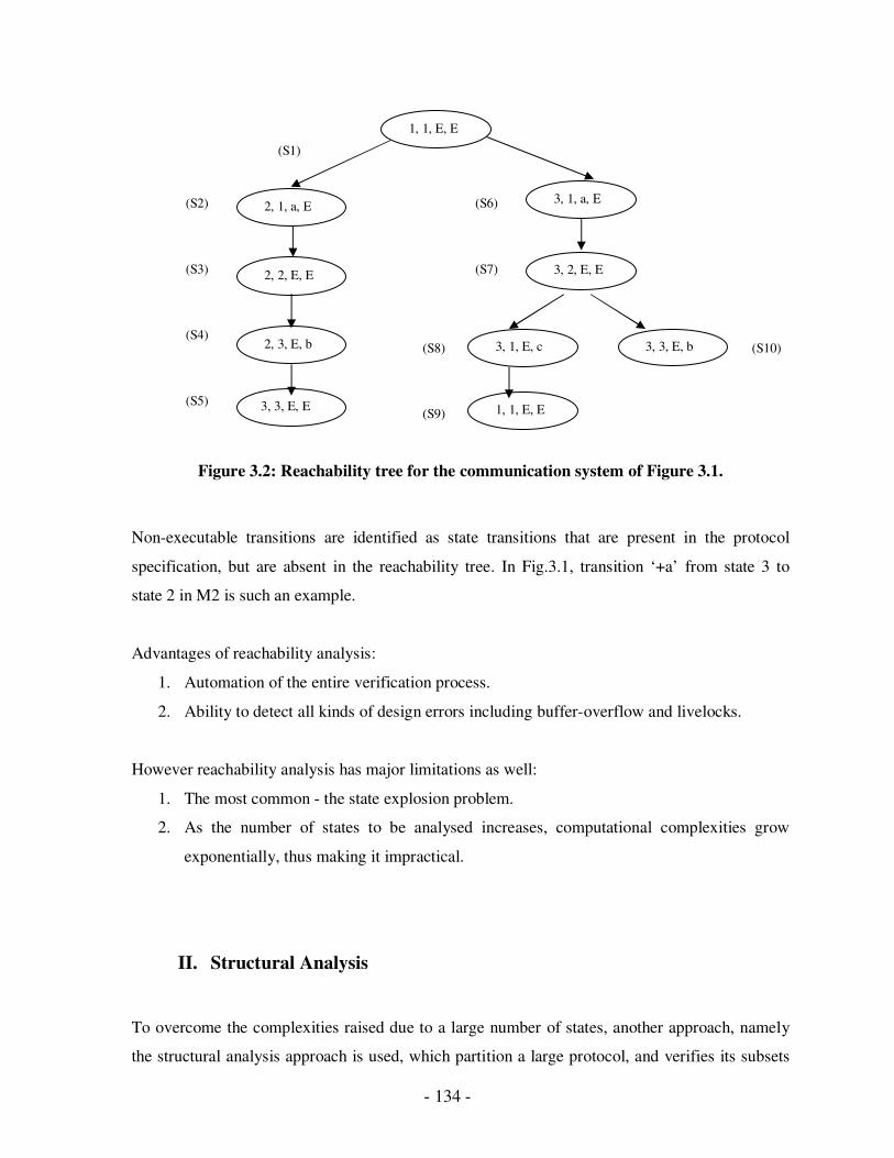
- 134 -
Figure 3.2: Reachability tree for the communication system of Figure 3.1.
Non-executable transitions are identified as state transitions that are present in the protocol
specification, but are absent in the reachability tree. In Fig.3.1, transition ‘+a’ from state 3 to
state 2 in M2 is such an example.
Advantages of reachability analysis:
1. Automation of the entire verification process.
2. Ability to detect all kinds of design errors including buffer-overflow and livelocks.
However reachability analysis has major limitations as well:
1. The most common - the state explosion problem.
2. As the number of states to be analysed increases, computational complexities grow
exponentially, thus making it impractical.
II. Structural Analysis
To overcome the complexities raised due to a large number of states, another approach, namely
the structural analysis approach is used, which partition a large protocol, and verifies its subsets
1, 1, E, E
3, 2, E, E 2, 2, E, E
3, 1, a, E 2, 1, a, E
1, 1, E, E 3, 3, E, E
3, 1, E, c 2, 3, E, b 3, 3, E, b
(S1)
(S9)
(S2)
(S3)
(S4)
(S5)
(S6)
(S7)
(S8) (S10)

- 135 -
to counteract the complexity of analysis. Reachability analysis is performed for each protocol
partition, and the results are combined to infer the correctness of the entire protocol. This analysis
procedure is for balanced protocols, in which the finite state graphs representing the CFSMs, are
isomorphic i.e. have a one-to-one correspondence. An example of such a protocol is shown in
Figure 3.3.
Figure 3.3: An example of a balanced protocol.
During the decomposition approach of structural analysis, the protocol graph is partitioned into
subgraphs. Each of these subgraphs contain one unique header node and zero or more exit nodes.
In a case when there is no exit node in a subgraph, the header node can also serve as an exit node.
These subgraphs in the structural partition can only be connected by the exit node of one, to the
header node of the other. A minimal subgraph consists of a single node. A schematic structural
partition of a protocol in two subgraphs can be shown as in Figure 3.4.
Figure 3.4: The structural partitions for a balanced protocol.
Gi U h
Gj
h
Gi’ U h’
Gj’
h’
M1 M2
+e / +a / -b
+c +c / -d
+e +e
+a +c / +e
/ -a
-e +b
+d +f
5
4 3
2
1 0
+e / +a / -b
+c +c / -d
+e
+e
+a +c / +e / -a
-e +b
+d +f
5
4 3
2
1 0
- 136 -
For M1, let Gi U h denote the union of subgraph Gi with the header node h of its successor
subgraph Gj. Let their corresponding counterparts in M2 be subgraphs Gi’ U h’ and Gj’
respectively. If the processes exchange events while M1 is in Gi U h and M2 is in Gi’ U h’ or
when M1 is in Gj and M2 is in Gj’, then this interaction is referred to as expected interaction
between subgraphs. If the processes exchange events while M1 is in Gi U h or Gj and M2 is in
Gj’ or Gi’ U h’ respectively, this interaction is called cross interaction between subgraphs.
Cross interaction between subgraphs can occur as a result of one process racing ahead of the
other. The purpose of this technique is to partition the protocol such that cross interactions are
eliminated. Let us denote the protocol graph in Figure 3.4 (Gi U Gj and Gi’ U Gj’). If there are
no cross interactions between the subgraphs in Figure 3.1, the reachability tree of the protocol
will be the union of the reachability tree of (Gi U h and Gi’ U h’) and the reachability tree of (Gj
and Gj’) over the global state <h, h’, 0, 0> plus a transition region. The transition region
represents the intermediate states when one process races ahead of the other. So the correctness
of the subgraphs implies the correctness of the protocol. For a protocol subgraph, if there are
deadlocks or unspecified receptions then these errors have to be distinguished as definite or
potential errors. The latter is an error that may vanish as a result of forming larger partitions. This
happens because the current partition is too fine and as a result, there is cross interaction between
graphs. A definite error is not only one for the protocol subgraph, but will become an error for
the entire protocol graph as well.
Advantages:
1. Since an entire protocol is divided into subgraphs, validation of individual graph can be
done independently and simultaneously.
2. This technique also explores all the global states in the state space of a protocol, but
divides this task to smaller subtasks, which can be performed independently and then
combined later.
Disadvantages:
1. Partitioning can require extra computational complexity.
2. It may not always be possible to eliminate cross interactions.
3. This technique is applicable only for balanced protocols.
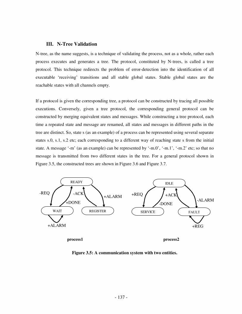
- 137 -
III. N-Tree Validation
N-tree, as the name suggests, is a technique of validating the process, not as a whole, rather each
process executes and generates a tree. The protocol, constituted by N-trees, is called a tree
protocol. This technique redirects the problem of error-detection into the identification of all
executable ‘receiving’ transitions and all stable global states. Stable global states are the
reachable states with all channels empty.
If a protocol is given the corresponding tree, a protocol can be constructed by tracing all possible
executions. Conversely, given a tree protocol, the corresponding general protocol can be
constructed by merging equivalent states and messages. While constructing a tree protocol, each
time a repeated state and message are renamed, all states and messages in different paths in the
tree are distinct. So, state s (as an example) of a process can be represented using several separate
states s.0, s.1, s.2 etc; each corresponding to a different way of reaching state s from the initial
state. A message ‘-m’ (as an example) can be represented by ‘-m.0’, ‘-m.1’, ‘-m.2’ etc; so that no
message is transmitted from two different states in the tree. For a general protocol shown in
Figure 3.5, the constructed trees are shown in Figure 3.6 and Figure 3.7.
Figure 3.5: A communication system with two entities.
+ALARM
ACK
-REQ
+DONE
-ACK
READY
+ALARM
WAIT REGISTER
-ALARM
+REQ
-DONE
+ACK
IDLE
SERVICE FAULT
+REG
process1 process2
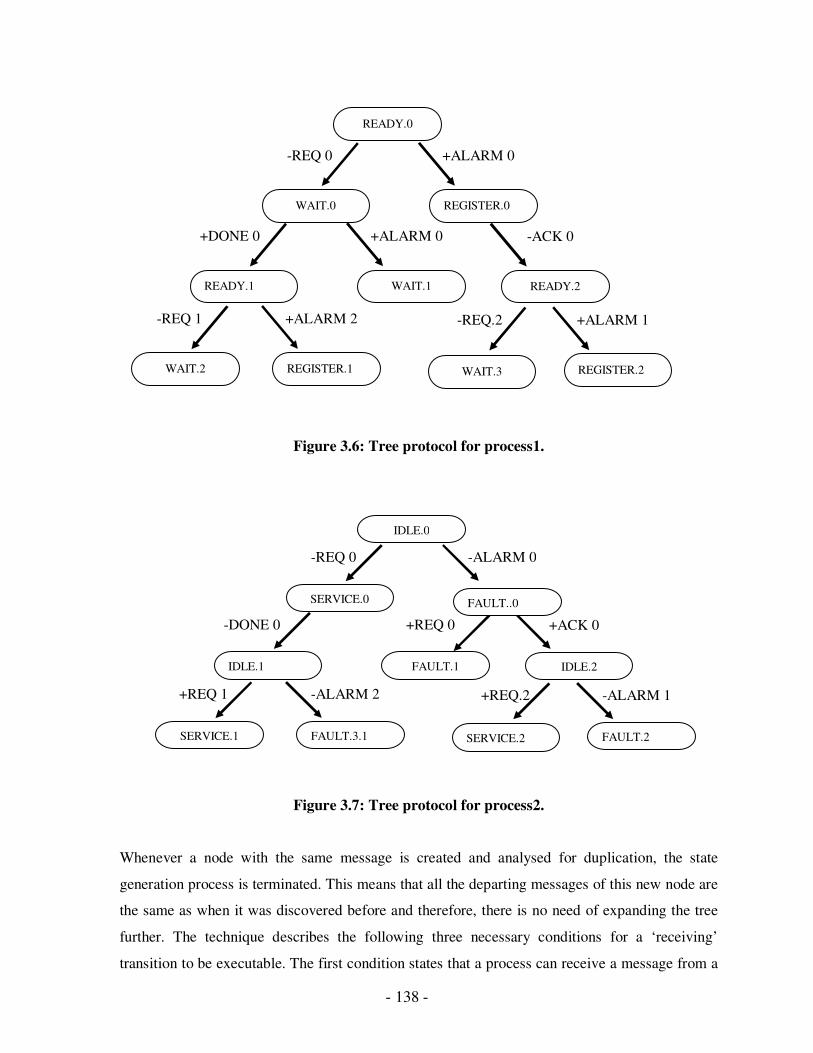
- 138 -
Figure 3.6: Tree protocol for process1.
Figure 3.7: Tree protocol for process2.
Whenever a node with the same message is created and analysed for duplication, the state
generation process is terminated. This means that all the departing messages of this new node are
the same as when it was discovered before and therefore, there is no need of expanding the tree
further. The technique describes the following three necessary conditions for a ‘receiving’
transition to be executable. The first condition states that a process can receive a message from a
-REQ 1
+DONE 0
-REQ 0 +ALARM 0
WAIT.0
READY.0
+ALARM 0
READY.1 WAIT.1
WAIT.2
+ALARM 2
REGISTER.1
-REQ.2
-ACK 0
+ALARM 1
REGISTER.2
REGISTER.0
WAIT.3
READY.2
+REQ 0 +ACK 0
IDLE.2
+REQ 1
-DONE 0
-REQ 0 -ALARM 0
SERVICE.0
IDLE.0
FAULT.1
SERVICE.1
-ALARM 2
FAULT.3.1
+REQ.2 -ALARM 1
FAULT.2
FAULT..0
IDLE.1
SERVICE.2
- 139 -
specific process only after it has received all messages previously sent by the same process. The
second condition assumes that the protocol consists of more than two processes. It states that if
process1 is to receive a message from process2 at state x, and process2 enters state y after having
sent that message, the last two states that process3 must have been reached before process1 has
reached state x and process2 has reached state y must be in predecessor-successor relation.
The third condition says that, in order for process1 to receive a message from process2 at state x,
the last state that process1 must have reached before process2 has sent the message, must be the
predecessor of the state x. Otherwise, process1 must have passed state x by the time the message
has been sent. Then, it is impossible to receive the message at state x for process1.
Advantages:
1. This technique can generate N trees for N-process protocol to divide the problem into
simpler sub-problems that make the whole task easier.
2. The generation of a large global tree is eliminated, thus reducing computational
complexity.
Disadvantages:
1. A limitation of the approach lies in the termination of the tree growth, which is
undecidable.
3.1.2 Partial Exploration Techniques
This section will describe the techniques in which only a partial state space of the protocol is
explored for the error detection. These techniques attempt to reduce complexity, and explore only
part of the global tree, using some criteria. They can generally work more efficiently than the
ones previously presented; however they also have limitations when compared to the exhaustive
search techniques.
- 140 -
I. Maximal Progress State Exploration
The maximal progress state exploration technique divides the task of reachable state generation
for a two-process protocol into two independent subtasks. The reachable state generation is
performed separately for each process. In each subtask, only states reachable by allowing one of
the two processes to make maximal progress, are generated and examined. The main problem
with exhaustive state exploration is the assumption that all reachable states of a protocol will be
generated in a particular order. One needs to consider all possible progress speeds for the two
processes. Also, one state can be generated many times since the same state can be reached by
many different progress speeds for the two processes.
The generated states are analysed against three types of a non-progress state: deadlock,
unspecified reception and channel overflow states. Another is called aprogress state. The
application of this procedure is shown for the two-process protocol in Figure 3.8. The processes
are forced to perform maximal progress as described by the following steps.
1. States are generated for process1 through ‘sending’ transitions and firable ‘receiving’
transitions of process1. This is done as much as possible, until transitions from the
current states are all unfirable ‘receiving’ transitions i.e an empty channel.
.
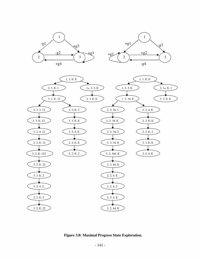
- 141 -
Figure 3.8: Maximal Progress State Exploration.
1
3 2
1
3 2
-g1
-g1
+g4
+g1
+g2
-g4
-g3
+g3
+g3
-g2 +g1
1, 1, E, E
3, 3, E, E 3, 1, E, 12
1R, 3, 3, E 2, 1, E, 1
3, 3, E, E 3, 3, E, 12
3, 2, E, 2 3, 3, 3, 12
2, 2, E, E 2, 2, E, 12
3, 2, 4, E 3, 2, 4, 12
3, 2, 4, 2
3, 3, E, 2
3, 2, E, 22
3, 2, E, 122 3, 2, E, 2
3, 2, E, 22
2, 2, E, 2
1, 1, E, E
2, 2, E, E 1, 2, 34, E
2, 1R, E, 1 1, 3, 3, E
2, 2, E, E 2, 2, 34, E
3, 2, 4, E 2, 2, 34, 1
3, 3, E, E 3, 3, 34, E
3, 2, E, 2 3, 2, 34, 2
3, 2, 4, 2
2, 2, 4, E
3, 2, 44, E
3, 2, 344, E 3, 2, 4, E
3, 2, 44, E
3, 3, 4, E
- 142 -
2. The same procedure is repeated for process2 through its ‘sending’ and firable ‘receiving’
transitions.
3. If all generated states of process1 and process2 are progress states, then the processes
have no non-progress states. Each generated state in Figure 3.8 is a progress state and
hence, the protocol is free from any non-progress states.
The state explorations in the first and second steps of the procedure are independent of each
other. If these two state explorations are executed in parallel, the time complexity requirement is
less than that in exhaustive state exploration techniques. If these are executed sequentially, the
required storage space is less than the exhaustive search techniques.
II. Reverse Reachability analysis
Reverse reachability analysis starts from some undesirable global states that are in the opposite
direction, and generates global states. If at any stage the initial global state can be reached during
this process of reverse reachability analysis, then the undesirable state is called a deadlock state.
Otherwise, the protocol is deadlock-free. It is a type of imaginary process the starts the process
from some suspected global state through a state transition diagram. This diagram is called the
reverse global state transition (RGST) diagram. If the states and the state transitions of the RGST
diagram are included in a path from a possible deadlock state to the initial state, the suspect is a
deadlock state. Also, for each ‘sending’ event in the reverse reachability analysis, there exists a
corresponding ‘receiving’ event that occurred before it.
For the two-process protocol shown in Figure 3.9, the reverse reachability analysis generates <2,
2, 0, 0> as one of the four suspect deadlock states. When this global state is used to generate
reverse paths, one of the four generated paths reaches the initial global state. This path is
presented as: <2, 2, 0, 0> �R <1, 2, 0, c> �R <1, 1, a, c> �R <0, 1, 0, c> �R <0, 0, 0, 0>. This
concludes the presence of deadlock in the protocol due to global state <2, 2, 0, 0>.
Advantages:
1. The reverse reachability analysis generally has a fewer number of global states generated
than the exhaustive search techniques, and therefore, performs better in most cases.

- 143 -
Disadvantages:
1. It can not detect all kinds of errors. Additionally, it also does not have independent
subtasks that can be performed in parallel when compared to other partial exploration
techniques.
Figure 3.9: A two-process protocol for reverse reachability analysis.
III. Random Walk State Exploration
To overcome the limitations of Reverse reachability analysis, Random walk state exploration
can be viewed as a modified form. In this technique, only one random transition from the
current state is analysed, instead of systemically exploring all transitions one by one. This
technique proposes to analyse only a part of whole transitions leading to some potential
errors, which is sufficient to identify the cause of the error.
Advantages:
1. This technique is simpler compared to previous methods.
0
3
2
1 1
0
2
3
C12
C21
-a +c
+d
-b +c
+c
+c -d
-c
+a
+a
+b
+a
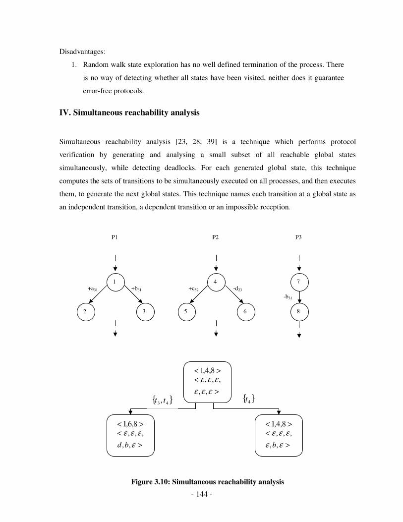
- 144 -
Disadvantages:
1. Random walk state exploration has no well defined termination of the process. There
is no way of detecting whether all states have been visited, neither does it guarantee
error-free protocols.
IV. Simultaneous reachability analysis
Simultaneous reachability analysis [23, 28, 39] is a technique which performs protocol
verification by generating and analysing a small subset of all reachable global states
simultaneously, while detecting deadlocks. For each generated global state, this technique
computes the sets of transitions to be simultaneously executed on all processes, and then executes
them, to generate the next global states. This technique names each transition at a global state as
an independent transition, a dependent transition or an impossible reception.
Figure 3.10: Simultaneous reachability analysis
-b31
-d23 +c32 +b31 +a31
P1
1
2 3
P2
4
5 6
P3
7
8
>< 8,4,1
>
<
εεε
εεε
,,
,,,
>< 8,6,1
>
<
ε
εεε
,,
,,,
bd
>< 8,4,1
>
<
εε
εεε
,,
,,,
b
{ }43 , tt { }4t

- 145 -
If a transition can be executed immediately at a global state, it is known as an independent
transition. A dependent transition is one that cannot be executed immediately. A ‘sending’
transition will be independent if its execution will not cause channel overflow, whereas a
‘receiving’ transition will be independent if its desired message is in the channel. A dependent
‘sending’ transition will cause channel overflow and a dependent ‘receiving’ transition cannot
receive a message as the channel is empty. When a transition is ‘receiving’ and the channel has
another message, the transition is called an impossible reception.
A maximum set of transitions from the union of the set of all dependent transitions, and a set of
all independent transitions form a candidate set of that global state if it includes: at most one of a
dependent transition or an independent transition of that global state from each process, and at
least one independent transition of that global state. For each such candidate set, the
simultaneously executable set is obtained by removing dependent transitions from that candidate
set. In simultaneous reachability analysis of a protocol, a global state generates another global
state if there exists a simultaneously executable set for the former, and the processes execute
simultaneously the transitions in that set. This technique generates a simultaneous reachability
graph in which nodes represent global states and arcs represent simultaneous global state
transition between global states. The application of this technique is shown for the fragment of a
three-process protocol in Figure 3.10 [23].
Advantages:
1. This technique has good concurrency control, thus avoiding unnecessary state space
generation.
Disadvantages:
1. It only analyses the simultaneous behaviour of the processes to detect all the deadlocks
and so, the number of global states explored are less than the exhaustive search
techniques.

- 146 -
3.2 CCSM
Entire communication systems can be viewed as a network of Finite State Machines,
though it is a very effective technique of validating and specifying the protocols but they
do not provide a compact higher level service view of a large and complex protocol.The
Communicating Finite State Machines (CFSM) Model has been widely used for specifying
and validating communication protocols for years. For a large and complex protocol, as the
number of states increases, so does the complexity. This increase in the number of states and
transitions will affect the clarity and presentation of the protocol. Therefore, we need a
technique to overcome this problem. This section details the concepts and terminologies of
the CCSM model, the advantages of this model over the CFSM model and also the types of
protocol design errors that can be encountered in CCSMs. which is based on the UML state
chart diagrams [40, 41, 29].
3.2.1 Complex State Machines
Complex State Machines (CSMs) are finite state machines whose states are themselves other
finite state machines. A network of CFSM consists of a set of finite state machines which
communicate asynchronously with each other. A client agent can download the CFSM
specifications published by the server, and follow that format and sequence in order to
converse. As the complexity of communication protocol increases, the CFSM specification
gets larger and thus consists of huge number of states. To improve the expressiveness of
specifications in such a case, we need a structuring mechanism that allows us to specify
protocols by stepwise refinement.

- 147 -
Figure 3.11: A sample CSM Agent with two complex states REGISTRATION and
BIDDING.
A complex state has other states embedded into it, which are called internal states and the state
machines using those states are known as internal FSM. This complexity gives modularity to the
state machine. Figure 3.11 shows a sample CSM M1 of a bidding agent who has three simple
states (IDLE, REQUEST and PAYMENT) and two complex states (REGISTRATION and
BIDDING). The complex states REGISTRATION and BIDDING are representing internal
FSM's M2 and M3 respectively. CSM M3 also has a complex state ‘s2’, which represents the
internal FSM M4. These complex states can each be viewed as a top-level service in the state
hierarchy, but the internal FSMs corresponding to them will represent the details and
complexities involved in them. Figure 3.11 is an example of a CSM that allows multi-level
complexity
-ccdetails
-request +catalog +rgstd -confirm
M1
-item -price +higher
+deal
-request -details +reject
r1 r2
r3
IDLE REQUEST REGISTRATION BIDDING PAYMENT
s1 s3
s4
s2
-model +unavail +avail
t1 t2
t3
M2 M3
M4
- 148 -
Due to the varying nature of the errors encountered with CSMs, the treatment of these errors also
differs. For instance, deadlocks occur when one state is waiting for a change from the second
state, and vice-versa. On the other hand, livelocks involve FSMs looping among states, without
really doing anything. Therefore, for FSMs with or without complex states, the treatment of
errors is computationally different due to the very nature of these errors.
The equivalent simple finite state machine of a CSM can be called a flattened state machine. The
advantages of our proposed model are discussed after defining CCSMs.
3.2.2 Communicating Complex State Machines
In this model, a protocol is defined as a network of two or more processes, represented as CSMs
that exchange messages over error-free simplex channels. A community of agents
communicating with each other via a protocol can be modelled using Communicating Complex
State Machines (CCSM). A complex state machine can communicate with either complex state
machines or simple states. This implies that the state machines do not necessarily need to reach
their complex states simultaneously.
Formally, a CCSM can be represented as the top-level FSM ( )TASqC f ,,,, where:
• C is the set of states where some states will be complex and other will be simple states.
Each complex state will correspond to an FSM.
• q is the initial state where Cq ∈
• fS is the set of final states where CS f ⊂
• A is the communicating alphabet which represents the set of valid message types.
• T is a map of state transitions ( )CAC ×× such that the CSM will move from the current
state to another state when applied with a transition.
The transition relation can be represented by a quadruple as ( )emth ,,, where:
• Ch ∈ is head of the transition i.e. the state where the transition originated.
• Ct ∈ is tail of the transition i.e. the state where the transition terminated.

- 149 -
• Am ∈ is the message that is sent or received.
• e is the ‘sending’ or ‘receiving’ event.
In the case where t is a complex state, the transition will result in placing the corresponding
FSM within the complex state in its initial state. In the case where h is a complex state, the
transition will only occur if the internal FSM of the complex state has reached one of its final
states. Figure 3.12 shows an example of two CCSMs communicating over channels C12 and C21.
3.2.3 Advantages of CCSM Model
The CCSM Model possesses the following advantages over the CFSM model:
It supports hierarchical decomposition of states by allowing nesting states within states. This
hierarchy allows the state machines to be viewed at different levels of granularity.
1. A significant sequence of states and transitions are replaced by a complex state. If the
state machine wants to use the same sequence again, it can reuse the complex state. In
such cases, the model will use an exponentially less numbers of states and transitions.
It supports modularity.
2. It presents a compact and higher level service behaviour of the entities in a protocol.
Each complex state can represent the part of the protocol involving other services.
Even the channels and alphabets used in the internal FSMs can be different from the
higher level, but they should have specifications of these.
3. For strict CSMs, where a complex state can only talk to another specified complex
state, the protocol validation of the complex states can be performed in parallel, and
the results can be combined for the entire protocol validation.
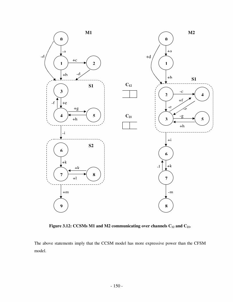
- 150 -
Figure 3.12: CCSMs M1 and M2 communicating over channels C12 and C21.
The above statements imply that the CCSM model has more expressive power than the CFSM
model.
S1
-d
0
1
3
4
6
5
8 7
1
0
2
3
4
5
7
6
8
2
9
-a +a
+c
-e +e
+b -d +b
+d
+h
-e
+f -f
-c
+k
+i
-i
+h
-g
+g
+k +k -l
+l
-m +m
C12
C21
M1 M2
S1
S2
- 151 -
3.2.4 Protocol Errors
The most common errors occurring in communicating FSMs are deadlocks, unspecified
receptions, non-executable transitions and buffer overflows. These errors can occur at the top
level or in the internal FSM level of a CSM. They are classified as follows:
� Simple Protocol Errors
Consider a case when all the CCSMs are in one of their simple states and an error occurs then
it is called simple protocol errors. Figure 3.12 shows an example of two CCSMs
communicating over channels C12 and C21. M1 and M2 starting initially from ‘0’. M1 sends
‘a’ and moves to state 1. M2 receives ‘a’ and moves to state 1 as well. Now, M1 is waiting to
receive ‘b’ or ‘c’ and M2 is also waiting to receive ‘b’ in order to move further. As both the
machines are waiting for each other to send the expected message, global state 1,1 is a
deadlock. As state 1 in both M1 and M2 is a simple state, this is an example of simple
deadlock.
� Complex Protocol Errors
Complex errors occur in the internal FSM’s of CCSMs. Errors occurring when all CCSMs are in
one of their complex states are called complex protocol errors. In Figure 3.12, M1 and M2 are
initially in state 0. M1 send ‘d’ and moves to complex state S1. Since the initial state of S1 is 3,
M1 is now in state 3. M2 receives‘d’ and moves to initial state 2 of complex state S1 as well.
From state 2, M2 sends ‘e’ and moves to state 3 in the internal FSM. M1 receives ‘e’ and moves
to state 4 of internal FSM. M2 sends g and moves to 5 and M1 receives g and moves to state 5.
Now, M2 and M1 are both waiting for message ‘h’ to arrive from each other. As M1 and M2 are
both in their complex states, the global state 1,1 SS or precisely 5,5 is an example of a complex
deadlock.
� Hybrid Protocol Errors
Errors occurring when some of the CCSMs are in simple states while the rest are in complex
states, are called hybrid protocol errors.
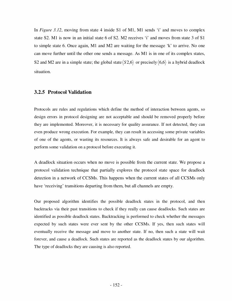
- 152 -
In Figure 3.12, moving from state 4 inside S1 of M1, M1 sends ‘i’ and moves to complex
state S2. M1 is now in an initial state 6 of S2. M2 receives ‘i’ and moves from state 3 of S1
to simple state 6. Once again, M1 and M2 are waiting for the message ‘k’ to arrive. No one
can move further until the other one sends a message. As M1 is in one of its complex states,
S2 and M2 are in a simple state; the global state 6,2S or precisely 6,6 is a hybrid deadlock
situation.
3.2.5 Protocol Validation
Protocols are rules and regulations which define the method of interaction between agents, so
design errors in protocol designing are not acceptable and should be removed properly before
they are implemented. Moreover, it is necessary for quality assurance. If not detected, they can
even produce wrong execution. For example, they can result in accessing some private variables
of one of the agents, or wasting its resources. It is always safe and desirable for an agent to
perform some validation on a protocol before executing it.
A deadlock situation occurs when no move is possible from the current state. We propose a
protocol validation technique that partially explores the protocol state space for deadlock
detection in a network of CCSMs. This happens when the current states of all CCSMs only
have ‘receiving’ transitions departing from them, but all channels are empty.
Our proposed algorithm identifies the possible deadlock states in the protocol, and then
backtracks via their past transitions to check if they really can cause deadlocks. Such states are
identified as possible deadlock states. Backtracking is performed to check whether the messages
expected by such states were ever sent by the other CCSMs. If yes, then such states will
eventually receive the message and move to another state. If no, then such a state will wait
forever, and cause a deadlock. Such states are reported as the deadlock states by our algorithm.
The type of deadlocks they are causing is also reported.

- 153 -
This section presents our algorithm to detect deadlocks for two CCSMs. The algorithm has three
procedures
1. To generate possible deadlock states
2. Detect them for the presence of deadlock
3. Determine the type of deadlock.
• Algorithm
A deadlock occurs when states have all ‘receiving’ departing transitions with empty
channels. The output transitional characteristics are set true for a state if this is the case.
Otherwise its output transitional characteristic is set to false. The Deadlock Detection (DD)
procedure calls the Possible Deadlock States (PDS) procedure to generate all the possible
local deadlock states for each CSM. The DD procedure generates their combination to see if
it can create a deadlock. If yes, then it applies Backtrack procedure to each of them.
These procedures can be applied to protocols dealing with two CCSMs but their channel
capacity is assumed to be one. Although the algorithm can easily be extended for a network
of more than two CCSMs, and channels with more capacity and there are some drawbacks to
this. Firstly, deadlock detection would be looking for all combinations of input transitional
characteristics from the different CCSMs, thus compromising scalability. Memory usage
would also be high due to the amount of processing power required.
Figure 3.13 shows the PDS procedure, which is called once for each CCSM. It generates all
possible local deadlock states by determining the output transitional characteristics of all the
states. This procedure also generates input transitional characteristics of the states, which are
used by the DD procedure to check whether the combination of two local states, one from
each CCSM, can cause a global deadlock state.
Input: S – set of states in the given CCSM as: (name, isFinal, isComplex).
T – set of transitions for all states in the given CCSM as:
(trans_from, event, message, trans_to).
Output: P – set of possible deadlock states in the given CCSM.
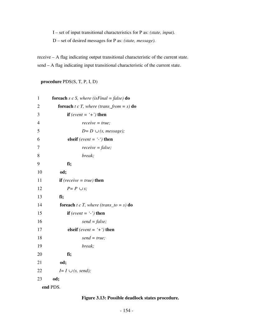
- 154 -
I – set of input transitional characteristics for P as: (state, input).
D – set of desired messages for P as: (state, message).
receive – A flag indicating output transitional characteristic of the current state.
send – A flag indicating input transitional characteristic of the current state.
procedure PDS(S, T, P, I, D)
1 foreach s є S, where (isFinal = false) do
2 foreach t є T, where (trans_from = s) do
3 if (event = ‘+’) then
4 receive = true;
5 D= D ∪ (s, message);
6 elseif (event = ‘-‘) then
7 receive = false;
8 break;
9 fi;
10 od;
11 if (receive = true) then
12 P= P ∪ s;
13 fi;
14 foreach t є T, where (trans_to = s) do
15 if (event = ‘-’) then
16 send = false;
17 elseif (event = ‘+‘) then
18 send = true;
19 break;
20 fi;
21 od;
22 I= I ∪ (s, send);
23 od;
end PDS.
Figure 3.13: Possible deadlock states procedure.
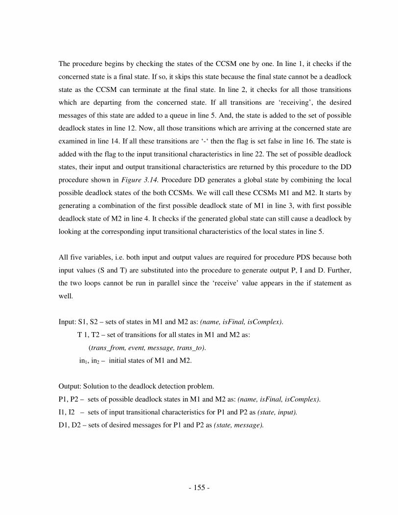
- 155 -
The procedure begins by checking the states of the CCSM one by one. In line 1, it checks if the
concerned state is a final state. If so, it skips this state because the final state cannot be a deadlock
state as the CCSM can terminate at the final state. In line 2, it checks for all those transitions
which are departing from the concerned state. If all transitions are ‘receiving’, the desired
messages of this state are added to a queue in line 5. And, the state is added to the set of possible
deadlock states in line 12. Now, all those transitions which are arriving at the concerned state are
examined in line 14. If all these transitions are ‘-‘ then the flag is set false in line 16. The state is
added with the flag to the input transitional characteristics in line 22. The set of possible deadlock
states, their input and output transitional characteristics are returned by this procedure to the DD
procedure shown in Figure 3.14. Procedure DD generates a global state by combining the local
possible deadlock states of the both CCSMs. We will call these CCSMs M1 and M2. It starts by
generating a combination of the first possible deadlock state of M1 in line 3, with first possible
deadlock state of M2 in line 4. It checks if the generated global state can still cause a deadlock by
looking at the corresponding input transitional characteristics of the local states in line 5.
All five variables, i.e. both input and output values are required for procedure PDS because both
input values (S and T) are substituted into the procedure to generate output P, I and D. Further,
the two loops cannot be run in parallel since the ‘receive’ value appears in the if statement as
well.
Input: S1, S2 – sets of states in M1 and M2 as: (name, isFinal, isComplex).
T 1, T2 – set of transitions for all states in M1 and M2 as:
(trans_from, event, message, trans_to).
in1, in2 – initial states of M1 and M2.
Output: Solution to the deadlock detection problem.
P1, P2 – sets of possible deadlock states in M1 and M2 as: (name, isFinal, isComplex).
I1, I2 – sets of input transitional characteristics for P1 and P2 as (state, input).
D1, D2 – sets of desired messages for P1 and P2 as (state, message).
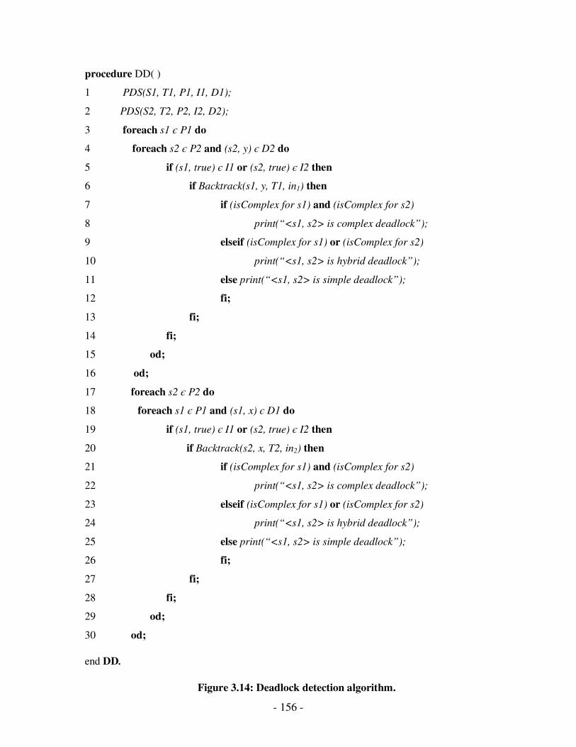
- 156 -
procedure DD( )
1 PDS(S1, T1, P1, I1, D1);
2 PDS(S2, T2, P2, I2, D2);
3 foreach s1 є P1 do
4 foreach s2 є P2 and (s2, y) є D2 do
5 if (s1, true) є I1 or (s2, true) є I2 then
6 if Backtrack(s1, y, T1, in1) then
7 if (isComplex for s1) and (isComplex for s2)
8 print(“<s1, s2> is complex deadlock”);
9 elseif (isComplex for s1) or (isComplex for s2)
10 print(“<s1, s2> is hybrid deadlock”);
11 else print(“<s1, s2> is simple deadlock”);
12 fi;
13 fi;
14 fi;
15 od;
16 od;
17 foreach s2 є P2 do
18 foreach s1 є P1 and (s1, x) є D1 do
19 if (s1, true) є I1 or (s2, true) є I2 then
20 if Backtrack(s2, x, T2, in2) then
21 if (isComplex for s1) and (isComplex for s2)
22 print(“<s1, s2> is complex deadlock”);
23 elseif (isComplex for s1) or (isComplex for s2)
24 print(“<s1, s2> is hybrid deadlock”);
25 else print(“<s1, s2> is simple deadlock”);
26 fi;
27 fi;
28 fi;
29 od;
30 od;
end DD.
Figure 3.14: Deadlock detection algorithm.
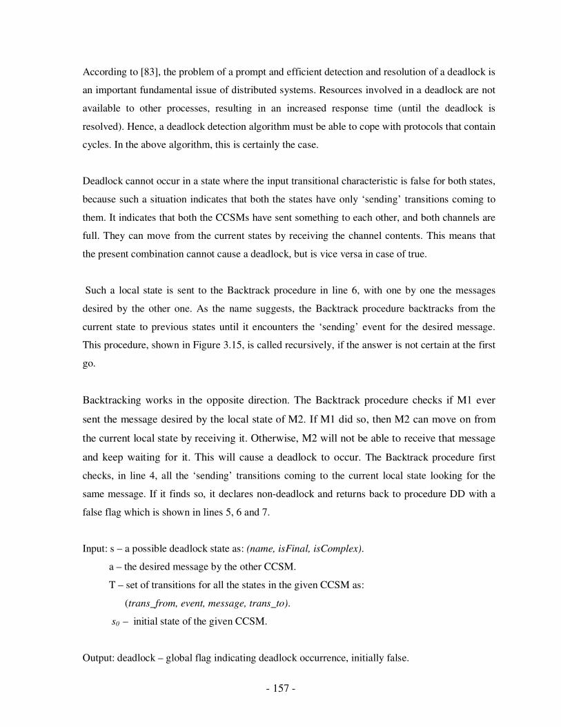
- 157 -
According to [83], the problem of a prompt and efficient detection and resolution of a deadlock is
an important fundamental issue of distributed systems. Resources involved in a deadlock are not
available to other processes, resulting in an increased response time (until the deadlock is
resolved). Hence, a deadlock detection algorithm must be able to cope with protocols that contain
cycles. In the above algorithm, this is certainly the case.
Deadlock cannot occur in a state where the input transitional characteristic is false for both states,
because such a situation indicates that both the states have only ‘sending’ transitions coming to
them. It indicates that both the CCSMs have sent something to each other, and both channels are
full. They can move from the current states by receiving the channel contents. This means that
the present combination cannot cause a deadlock, but is vice versa in case of true.
Such a local state is sent to the Backtrack procedure in line 6, with one by one the messages
desired by the other one. As the name suggests, the Backtrack procedure backtracks from the
current state to previous states until it encounters the ‘sending’ event for the desired message.
This procedure, shown in Figure 3.15, is called recursively, if the answer is not certain at the first
go.
Backtracking works in the opposite direction. The Backtrack procedure checks if M1 ever
sent the message desired by the local state of M2. If M1 did so, then M2 can move on from
the current local state by receiving it. Otherwise, M2 will not be able to receive that message
and keep waiting for it. This will cause a deadlock to occur. The Backtrack procedure first
checks, in line 4, all the ‘sending’ transitions coming to the current local state looking for the
same message. If it finds so, it declares non-deadlock and returns back to procedure DD with a
false flag which is shown in lines 5, 6 and 7.
Input: s – a possible deadlock state as: (name, isFinal, isComplex).
a – the desired message by the other CCSM.
T – set of transitions for all the states in the given CCSM as:
(trans_from, event, message, trans_to).
s0 – initial state of the given CCSM.
Output: deadlock – global flag indicating deadlock occurrence, initially false.
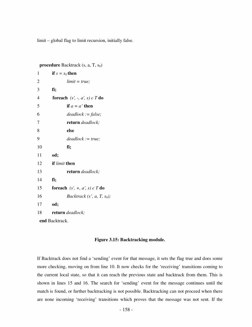
- 158 -
limit – global flag to limit recursion, initially false.
procedure Backtrack (s, a, T, s0)
1 if s = s0 then
2 limit = true;
3 fi;
4 foreach (s', -, a', s) є T do
5 if a = a’ then
6 deadlock := false;
7 return deadlock;
8 else
9 deadlock := true;
10 fi;
11 od;
12 if limit then
13 return deadlock;
14 fi;
15 foreach (s', +, a', s) є T do
16 Backtrack (s’, a, T, s0);
17 od;
18 return deadlock;
end Backtrack.
Figure 3.15: Backtracking module.
If Backtrack does not find a ‘sending’ event for that message, it sets the flag true and does some
more checking, moving on from line 10. It now checks for the ‘receiving’ transitions coming to
the current local state, so that it can reach the previous state and backtrack from them. This is
shown in lines 15 and 16. The search for ‘sending’ event for the message continues until the
match is found, or further backtracking is not possible. Backtracking can not proceed when there
are none incoming ‘receiving’ transitions which proves that the message was not sent. If the
- 159 -
search continues until the initial state is found, then we allow just one more go, by setting the flag
limit to true in lines 1 and 2. This checks the incoming ‘sending’ transitions and returns the
current value of the flag in line 13.
When procedure DD becomes true as the return value from Backtrack in line 6, it checks the
isComplex property of both the local states to see what kind of deadlock the combination is.
When isComplex property is true for both the local states in line 7, the generated global state is
called a complex deadlock state. If isComplex property is true for one and false for the other in
line 9, the global state is called the hybrid deadlock state. When isComplex is false for both the
local states in line 11, the resulting global state is called a simple deadlock state.
After concluding that a global state is or is not a deadlock, procedure DD generates another
global state by combining the first local state of M1 with the second local state of M2 and so on
with all possible deadlock states of M2 as shown in lines 3 and 4. The same process is repeated
from line 17 to 30 for the local states of M2 and they are one by one combined with all the
possible deadlock states of M1. Each time the algorithm checks if the generated combination can
still cause a deadlock by looking at the corresponding input transitional characteristics of the
local states.
3.3 Implementation
This chapter provides the details of the implementation of our proposed algorithm. First, we
describe the XML specification of CCSMs, and then illustrate how the parsing of this
specification is done to store useful information in data structures. We give functionalities of
the classes created in this implementation.
3.3.1 XML Specification
In Communicating Complex State Machines (CCSMs) or Communicating Finite State Machines
(CFSMs), the protocol is defined in the XML format. The Document Type Definition (DTD) of
the state machine specification is shown in Figure 3.16. Figures 3.17 and 3.18 have been shown
for the purpose of illustrating the XML specification.

- 160 -
Figure 3.16: Top level view of a CCSM.
Figure 3.17: An internal FSM.
<?xml version=“1.0”?>
<!DOCTYPE CCSM [
<!ELEMENT CCSM (StateMachine+)>
<!ELEMENT StateMachine (State+)>
<!ATTLIST StateMachine name CDATA #REQUIRED>
<!ELEMENT State (StateTransition+)>
<!ATTLIST State name CDATA #REQUIRED>
<!ATTLIST State final CDATA # REQUIRED>
<!ATTLIST State complex CDATA # REQUIRED>
<!ELEMENT StateTransition (event, message transition)>
<!ELEMENT event (#PCDATA)>
<!ELEMENT message (#PCDATA)>
<!ELEMENT transition (#PCDATA)>
]>
Figure 3.18: DTD for state machine specification
-ccdetails
-request +catalog +rgstd -confirm
M1
IDLE REQUEST REGISTRATION BIDDING PAYMENT
M2 M3
-request -details
+reject
r1 r2
r3
M2
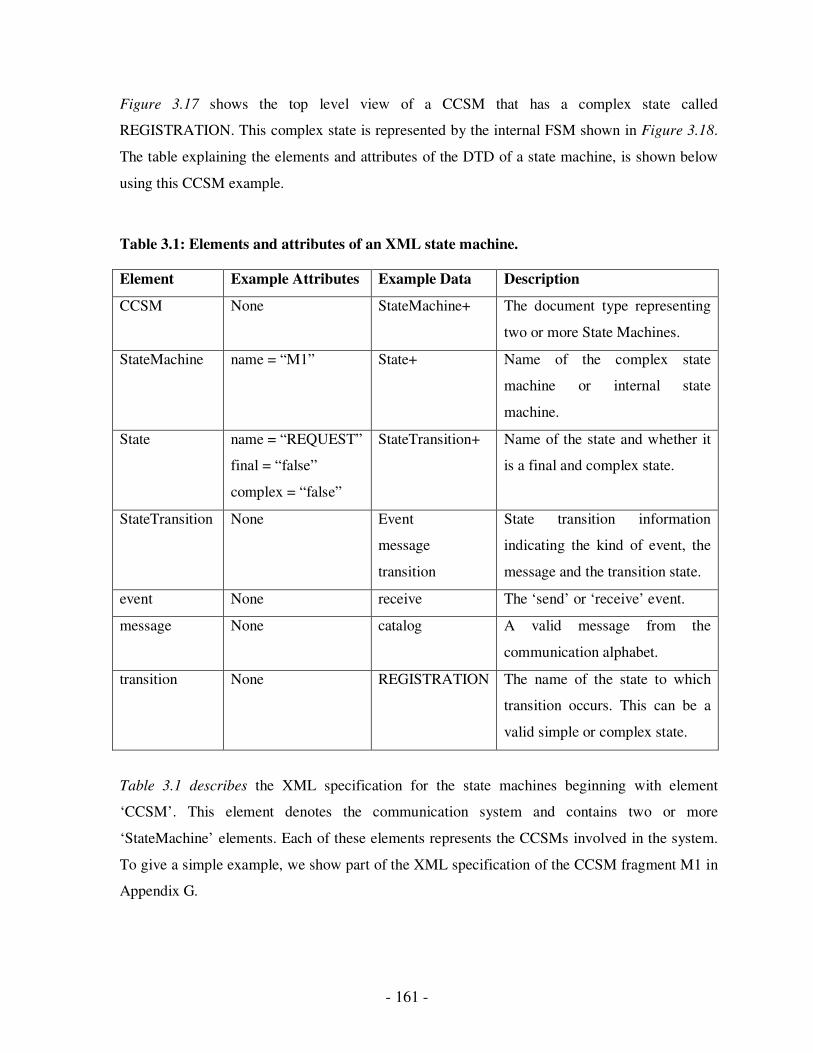
- 161 -
Figure 3.17 shows the top level view of a CCSM that has a complex state called
REGISTRATION. This complex state is represented by the internal FSM shown in Figure 3.18.
The table explaining the elements and attributes of the DTD of a state machine, is shown below
using this CCSM example.
Table 3.1: Elements and attributes of an XML state machine.
Element Example Attributes Example Data Description
CCSM None StateMachine+ The document type representing
two or more State Machines.
StateMachine name = “M1” State+ Name of the complex state
machine or internal state
machine.
State name = “REQUEST”
final = “false”
complex = “false”
StateTransition+ Name of the state and whether it
is a final and complex state.
StateTransition None Event
message
transition
State transition information
indicating the kind of event, the
message and the transition state.
event None receive The ‘send’ or ‘receive’ event.
message None catalog A valid message from the
communication alphabet.
transition None REGISTRATION The name of the state to which
transition occurs. This can be a
valid simple or complex state.
Table 3.1 describes the XML specification for the state machines beginning with element
‘CCSM’. This element denotes the communication system and contains two or more
‘StateMachine’ elements. Each of these elements represents the CCSMs involved in the system.
To give a simple example, we show part of the XML specification of the CCSM fragment M1 in
Appendix G.
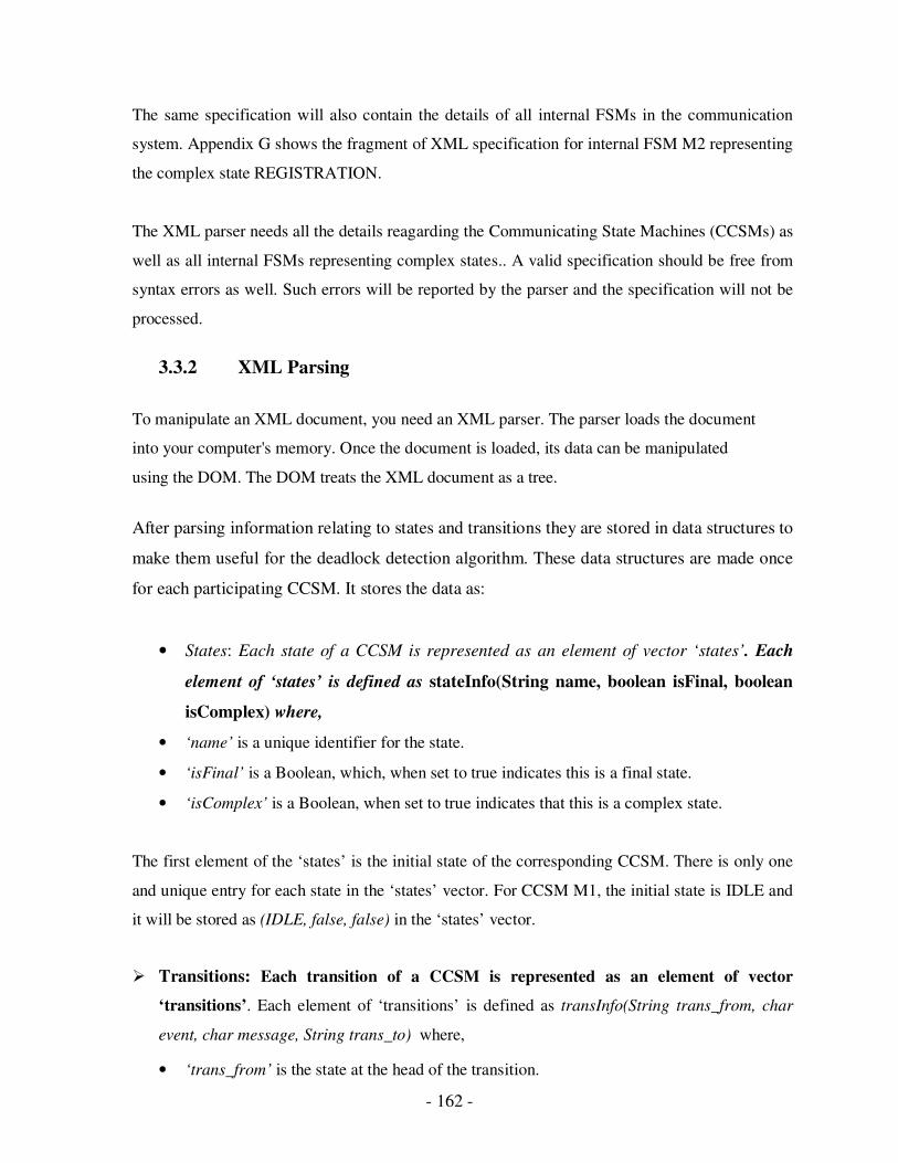
- 162 -
The same specification will also contain the details of all internal FSMs in the communication
system. Appendix G shows the fragment of XML specification for internal FSM M2 representing
the complex state REGISTRATION.
The XML parser needs all the details reagarding the Communicating State Machines (CCSMs) as
well as all internal FSMs representing complex states.. A valid specification should be free from
syntax errors as well. Such errors will be reported by the parser and the specification will not be
processed.
3.3.2 XML Parsing
To manipulate an XML document, you need an XML parser. The parser loads the document
into your computer's memory. Once the document is loaded, its data can be manipulated
using the DOM. The DOM treats the XML document as a tree.
After parsing information relating to states and transitions they are stored in data structures to
make them useful for the deadlock detection algorithm. These data structures are made once
for each participating CCSM. It stores the data as:
• States: Each state of a CCSM is represented as an element of vector ‘states’. Each
element of ‘states’ is defined as stateInfo(String name, boolean isFinal, boolean
isComplex) where,
• ‘name’ is a unique identifier for the state.
• ‘isFinal’ is a Boolean, which, when set to true indicates this is a final state.
• ‘isComplex’ is a Boolean, when set to true indicates that this is a complex state.
The first element of the ‘states’ is the initial state of the corresponding CCSM. There is only one
and unique entry for each state in the ‘states’ vector. For CCSM M1, the initial state is IDLE and
it will be stored as (IDLE, false, false) in the ‘states’ vector.
� Transitions: Each transition of a CCSM is represented as an element of vector
‘transitions’. Each element of ‘transitions’ is defined as transInfo(String trans_from, char
event, char message, String trans_to) where,
• ‘trans_from’ is the state at the head of the transition.

- 163 -
• ‘event’ indicates a receive event when +, and send event when -.
• ‘message’ represents the data sent or received.
• ‘trans_to’ is the state at the tail of the transition.
An example of transition will be (IDLE, send, request, REQUEST) which is the first transition in
the state machine. When parsing a CCSM, transitions coming towards a complex state are
replaced as the transitions coming towards the initial state of the internal FSM representing that
complex state. In the same way, transitions going out of a complex state are replaced as
transitions going out from the final states of internal FSM representing that complex state.
As an example in M1, the transition (REQUEST, receive, catalog, REGISTRATION) will actually
be stored as (REQUEST, receive, catalog, r1), as ‘r1’ is the initial state internal FSM representing
REGISTRATION. The same way transition (REGISTRATION, receive, rgstd, BIDDING) will
actually be stored as (r4, receive, rgstd, s1) where ‘r4’ is the final state of REGISTRATION and
‘s1’ is the initial state of BIDDING.
� Outgoing Transitional Characteristics: These characteristics are derived from the
‘transitions’ vector for each state in ‘states’ vector. These are represented as an array of
booleans ‘output’ which has the same number of elements as in ‘states’. Also the entry
number in ‘output’ corresponds to the entry number in ‘states’. For example, the first
element of ‘output’ tells the outgoing transitional characteristic of the first state in
‘states’.
If all outgoing transitions from the first state of ‘states’ are receiving, the value of the first
element of ‘output’ will be true. If any of the transitions from the first state is sending, the value
of the first element will be false. This checking is performed for all states, and the flags are set to
‘output’ correspondingly. This array is used to generate the possible deadlock states in the
algorithm.
� Possible Deadlock States: A state is called a possible deadlock state if all the
outgoing transitions from it are ‘receiving’. Only such states can globally cause a
deadlock to occur because in case of an empty channel they cannot make a move, as there
is no ‘sending’ transition. If a CCSM is in one of such states, and the channel is empty, it
- 164 -
has to wait until the other CCSM sends a message. It might have to wait forever to
receive it and so, it can cause a deadlock.
The possible deadlock states for a CCSM are derived by looking at the output transitional
characteristics of all the states. For a state in ‘states’ vector, if the corresponding element in
‘output’ array is true then this state is called a possible deadlock state. The possible deadlock
states are stored in a vector ‘pds’, which forms a subset of the ‘states’ vector. So, each state of
‘pds’ is also defined as stateInfo(String name, boolean isFinal, boolean isComplex) as in the
‘states’ vector.
� Incoming Transitional Characteristics: These characteristics are derived from
‘transitions’ vector for each state in ‘pds’ vector. These are represented as an array of
booleans ‘input’, which has same number of elements as in ‘pds’. Also, the entry number
in ‘input’ corresponds to the entry number in ‘pds’. For example, the first element of
‘input’ tells the incoming transitional characteristic of the first possible deadlock state.
This array is used after generating the possible deadlock states in the algorithm to check if it can
be globally responsible for a deadlock. If all incoming transitions to the first state of ‘pds’ are
sending, the value of the first element of ‘input’ will be false. If any of the transitions to the first
state is receiving, the value of the first element will be true. This checking is done for all possible
deadlock states and the flags are set in ‘input’ correspondingly.
� Desired Messages: The expected messages for the possible deadlock states are
stored in a two dimensional array ‘desired’. The first dimension of this array is equal
to the number of elements in the ‘pds’ vector. The row number in the array corresponds
to the element number in the vector. For example, all the elements in the first row of the
array are the messages expected by the first possible deadlock state.
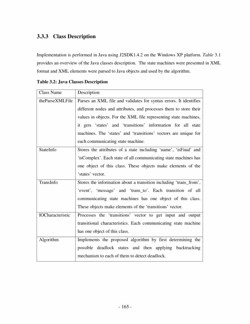
- 165 -
3.3.3 Class Description
Implementation is performed in Java using J2SDK1.4.2 on the Windows XP platform. Table 3.1
provides an overview of the Java classes description. The state machines were presented in XML
format and XML elements were parsed to Java objects and used by the algorithm.
Table 3.2: Java Classes Description
Class Name Description
theParseXMLFile Parses an XML file and validates for syntax errors. It identifies
different nodes and attributes, and processes them to store their
values in objects. For the XML file representing state machines,
it gets ‘states’ and ‘transitions’ information for all state
machines. The ‘states’ and ‘transitions’ vectors are unique for
each communicating state machine.
StateInfo Stores the attributes of a state including ‘name’, ‘isFinal’ and
‘isComplex’. Each state of all communicating state machines has
one object of this class. These objects make elements of the
‘states’ vector.
TransInfo Stores the information about a transition including ‘trans_from’,
‘event’, ‘message’ and ‘trans_to’. Each transition of all
communicating state machines has one object of this class.
These objects make elements of the ‘transitions’ vector.
IOCharacteristic Processes the ‘transitions’ vector to get input and output
transitional characteristics. Each communicating state machine
has one object of this class.
Algorithm Implements the proposed algorithm by first determining the
possible deadlock states and then applying backtracking
mechanism to each of them to detect deadlock.
- 166 -
3.3.4 Analysis
The analysis is done in two parts. Firstly, the complexity of our proposed validation technique is
provided. Then, a performance analysis is done and compared against two well known protocol
validation techniques.
• Complexity
Deadlock detection is a very important step in protocol validation. The proposed algorithm
takes the approach of partial state search technique for detecting deadlocks in a network of
CCSMs. This is important a global state space can grow enormously for a large and complex
protocol, thus limiting the number of generated states, leading to better time and space
complexity.
For time and space complexity of our algorithm, we look at the DD procedure in Figure 3.14.
The complexities will be given in terms of the number of states generated through the algorithm.
Since lines 3 to 16 and 17 to 30 can be performed in parallel, we will only consider one of these
parts for complexity analysis. Before executing these loops, the algorithm generates some
possible deadlock states. In most cases, the number of such states will be much less than the
number of total states in the communication system. For example, in Figures 3.21-3.26, for the
three communication systems total number of states are 9, 16 and 25, whereas the number of
generated possible deadlock states are 3, 2 and 2 only.
Since step1 and step2 can be performed in parallel, if the outer loop of line 3 to 16 of the DD
procedure is executed n times, and the inner loop is executed m times, the time complexity of our
algorithm will be O([m*b]n), where n and m are also the number of possible deadlock states in
two CCSMs, and b is the complexity of the Backtrack procedure. The best case for Backtrack
complexity will be if the message is found at the first try itself. Complexity in this case will be 1.
The worst case will be the generation of all the states in the state machine. The best case
complexity of DD will be O(mn). On average, the complexity can also be represented as
O([m*s]n), where s is the number of states in the state machine with m deadlock states.
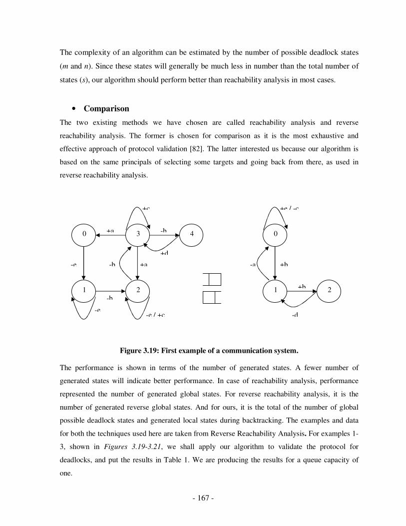
- 167 -
The complexity of an algorithm can be estimated by the number of possible deadlock states
(m and n). Since these states will generally be much less in number than the total number of
states (s), our algorithm should perform better than reachability analysis in most cases.
• Comparison
The two existing methods we have chosen are called reachability analysis and reverse
reachability analysis. The former is chosen for comparison as it is the most exhaustive and
effective approach of protocol validation [82]. The latter interested us because our algorithm is
based on the same principals of selecting some targets and going back from there, as used in
reverse reachability analysis.
Figure 3.19: First example of a communication system.
The performance is shown in terms of the number of generated states. A fewer number of
generated states will indicate better performance. In case of reachability analysis, performance
represented the number of generated global states. For reverse reachability analysis, it is the
number of generated reverse global states. And for ours, it is the total of the number of global
possible deadlock states and generated local states during backtracking. The examples and data
for both the techniques used here are taken from Reverse Reachability Analysis. For examples 1-
3, shown in Figures 3.19-3.21, we shall apply our algorithm to validate the protocol for
deadlocks, and put the results in Table 1. We are producing the results for a queue capacity of
one.
0
2
3
1 2 1
4 0 +a
-b
-e / +c
-b
-e +a
+c
-b
+d
+e / -c
+b -a
+b
-d -e
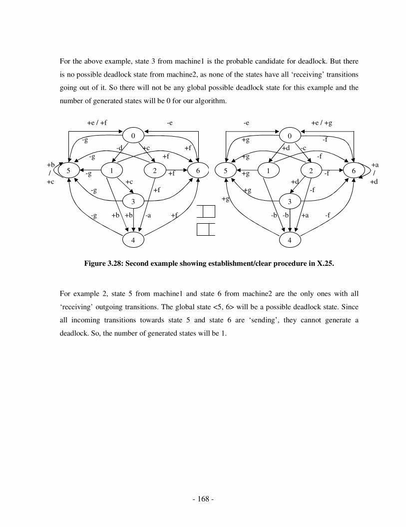
- 168 -
For the above example, state 3 from machine1 is the probable candidate for deadlock. But there
is no possible deadlock state from machine2, as none of the states have all ‘receiving’ transitions
going out of it. So there will not be any global possible deadlock state for this example and the
number of generated states will be 0 for our algorithm.
Figure 3.28: Second example showing establishment/clear procedure in X.25.
For example 2, state 5 from machine1 and state 6 from machine2 are the only ones with all
‘receiving’ outgoing transitions. The global state <5, 6> will be a possible deadlock state. Since
all incoming transitions towards state 5 and state 6 are ‘sending’, they cannot generate a
deadlock. So, the number of generated states will be 1.
+e / +f -e
-g
-d +c +f -g +f
+b
/ -g +f
+c +c -g +f
-g +b +b -a +f
0
5 1 2
3
4
6
-e +e / +g
+g -f
+d -c +g -f
+a
+g -f /
+d +d +g -f
+g
-b -b +a -f
0
5 1 2
3
4
6
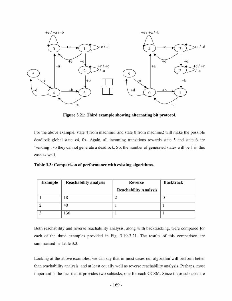
- 169 -
Figure 3.21: Third example showing alternating bit protocol.
For the above example, state 4 from machine1 and state 0 from machine2 will make the possible
deadlock global state <4, 0>. Again, all incoming transitions towards state 5 and state 6 are
‘sending’, so they cannot generate a deadlock. So, the number of generated states will be 1 in this
case as well.
Table 3.3: Comparison of performance with existing algorithms.
Example
Reachability analysis Reverse
Reachability Analysis
Backtrack
1 18 2 0
2 40 1 1
3 136 1 1
Both reachability and reverse reachability analysis, along with backtracking, were compared for
each of the three examples provided in Fig. 3.19-3.21. The results of this comparison are
summarised in Table 3.3.
Looking at the above examples, we can say that in most cases our algorithm will perform better
than reachability analysis, and at least equally well as reverse reachability analysis. Perhaps, most
important is the fact that it provides two subtasks, one for each CCSM. Since these subtasks are
+e / +a / -b
+c +c / -d
+e +e
+a +c / +e / -a
-e +b
+d +b
-c
5
4 3
2
1 0
+e / +a / -b
+c +c / -d
+e +e
+a +c / +e / -a
-e +b
+d +b
-c
5
4 3
2
1 0
- 170 -
independent of each other, and time and storage requirements of each subtask are less than the
total task, they can be performed simultaneously to save time and space. This property of our
algorithm is much different from the above two techniques.
In summary, a protocol is the backbone of a communication medium, and it becomes a more
crucial factor when working in a multi-agent environment. Here, we have discussed the various
techniques and algorithms used to validate protocol correctness and tested the proposed
validation techniques as well. A communication protocol should be validated against the
existence of logical errors to provide the quality assurance of a communication system.
Agents exchange information using a valid sequence that forms a communication protocol. The
behaviour of these agents can be modelled using a Communicating Finite State Machine
(CFSMs). But, CFSMs do not have much expressive power in providing a hierarchical view of a
complex protocol to reflect its differing levels of granularity. To overcome this limitation,
CCSMs are used, which provide the support of nested states.
We tested the operation of proposed validation techniques on various protocols, compared the
results of reachability analysis and reverse reachability analysis techniques. According to the
observations, a proposed validation technique is capable of detecting the presence, as well as the
absence of deadlock errors in the protocols. An algorithm can perform better than reachability
analysis, and almost equally well in many cases, and our algorithm provides one more option to
divide the analysis of possible deadlock states into two independent subtasks, which can be
executed in parallel, to reduce the time complexity of the analysis.
On the basis of these observations, we conclude that this proposed technique can handle protocol
validation and verification efficiently. The use of this protocol in various applications will be
explained in the next sections.
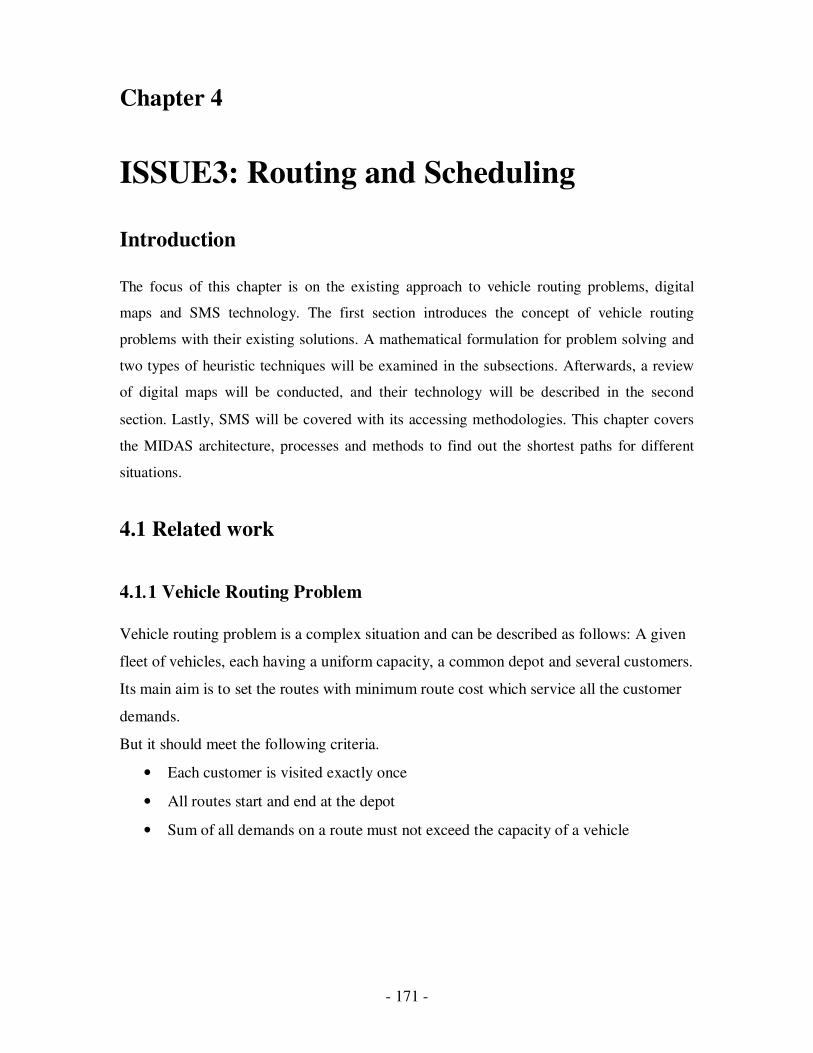
- 171 -
Chapter 4
ISSUE3: Routing and Scheduling
Introduction
The focus of this chapter is on the existing approach to vehicle routing problems, digital
maps and SMS technology. The first section introduces the concept of vehicle routing
problems with their existing solutions. A mathematical formulation for problem solving and
two types of heuristic techniques will be examined in the subsections. Afterwards, a review
of digital maps will be conducted, and their technology will be described in the second
section. Lastly, SMS will be covered with its accessing methodologies. This chapter covers
the MIDAS architecture, processes and methods to find out the shortest paths for different
situations.
4.1 Related work
4.1.1 Vehicle Routing Problem
Vehicle routing problem is a complex situation and can be described as follows: A given
fleet of vehicles, each having a uniform capacity, a common depot and several customers.
Its main aim is to set the routes with minimum route cost which service all the customer
demands.
But it should meet the following criteria.
• Each customer is visited exactly once
• All routes start and end at the depot
• Sum of all demands on a route must not exceed the capacity of a vehicle
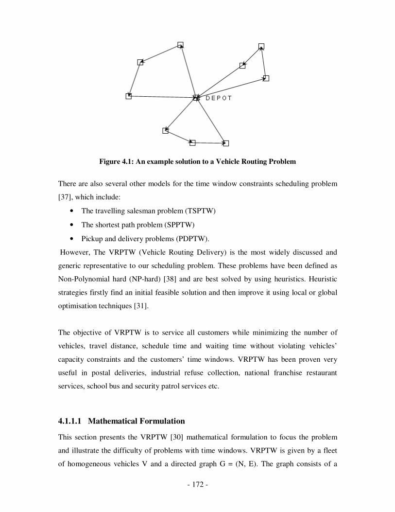
- 172 -
Figure 4.1: An example solution to a Vehicle Routing Problem
There are also several other models for the time window constraints scheduling problem
[37], which include:
• The travelling salesman problem (TSPTW)
• The shortest path problem (SPPTW)
• Pickup and delivery problems (PDPTW).
However, The VRPTW (Vehicle Routing Delivery) is the most widely discussed and
generic representative to our scheduling problem. These problems have been defined as
Non-Polynomial hard (NP-hard) [38] and are best solved by using heuristics. Heuristic
strategies firstly find an initial feasible solution and then improve it using local or global
optimisation techniques [31].
The objective of VRPTW is to service all customers while minimizing the number of
vehicles, travel distance, schedule time and waiting time without violating vehicles’
capacity constraints and the customers’ time windows. VRPTW has been proven very
useful in postal deliveries, industrial refuse collection, national franchise restaurant
services, school bus and security patrol services etc.
4.1.1.1 Mathematical Formulation
This section presents the VRPTW [30] mathematical formulation to focus the problem
and illustrate the difficulty of problems with time windows. VRPTW is given by a fleet
of homogeneous vehicles V and a directed graph G = (N, E). The graph consists of a

- 173 -
finite set of nodes N and a finite set of edges E. Let N = {0, 1, 2… n}, we denote the
central depot as {0} and the customers as {1… n}. The set of edges represents
connections between the depot and the customers, and among customers. Each edge e has
two endnotes i, j and is denoted by e (i, j), we associate a cost ci j and a time ti j , which
may include service time at customer i.
Every customer in the network must be visited only once by one of the vehicles. Each
vehicle has a limited capacity q, and each customer has a varying demand di. Each
customer must also be serviced within a pre-defined time window [ai, bi]. A vehicle must
arrive at the customer before bi. It can arrive before ai but the customer will not be
serviced before time bi. The depot also has a time window [a0, b0]. Vehicles may not
leave the depot before a0 and must be back before or at time b0. There are two types of
decision variables in VRPTW. The decision xi j k (i, j ∈ N; k ∈ V; i≠ j) is 1 if vehicle k
travels from node i to node j, and 0 otherwise. The decision variable si k denotes the time
vehicle k starts service at the customer i.
The following mathematical formulae are given from [1]:
Min ∑ k∈V ∑ i∈N ∑ j∈N ci j xi j k (1)
subject to
∑ k∈V ∑ j∈N xi j k = 1 ∀i ∈ N (2)
∑ i∈N di ∑ j∈N xi j k ≤ q ∀k ∈ V (3)
∑ j∈N x0 j k = 1 ∀k ∈ V (4)
∑ i∈N xi h k - ∑ j∈N xh j k = 0 ∀h ∈ N, ∀k ∈ V (5)
∑ i∈N xi,0, k = 1 ∀k ∈ V (6)
si k + ti j – K(1 – xi j k ) ≤ si k ∀i, j ∈ N, ∀k ∈ V (7)
ai ≤ si k ≤ bi ∀i ∈ N, ∀k ∈ V (8)
xi j k ∈ {0, 1} ∀i, j ∈ N, ∀k ∈ V (9)
The following constraints state that:
(2): each customer is serviced exactly once
- 174 -
(3): no vehicle is loaded with more than its permitted capacity.
(4), (5) and (6): each vehicle leaves the depot, arrives at a customer base, then leaves
again, and finally arrives back at the depot.
(7): a vehicle k cannot arrive at j before sik + tij if it is travelling from i to j. In formula (7)
K is a large scalar.
(8) time windows are observed, and
(9) An integral constraint.
4.1.1.2 Insertion Heuristic
Insertion heuristic is a fast and easy to use technology which provides a set of feasible
routes by repeatedly inserting an as of yet unrouted customer into a partially constructed.
The insertion heuristic was introduced by Solomon [30]. He concluded that the insertion
heuristic has an excellent performance, compared to savings heuristic, nearest neighbour
heuristic and sweep heuristic. The simple implementation of insertion heuristic is easily
adaptable in any development environment without time performance penalization.
Moreover, it can be combined into other techniques for building an initial solution due to
its fast performance.
The concept of insertion heuristic assumes a route R, where C0 is the first customer and
Cm is the last customer with their earliest and latest arrival times. The feasibility of
inserting a customer into route R is checked by inserting the customer between all edges
in the current route, and selecting the edge that has the lowest travel cost. For customer Ci
to be inserted between C0 and C1, the insertion feasibility depends upon checking, by
computation:
(1) The total load,
(2) The total travel time and
(3) The amount of time that the arrival time of t1 is pushed forward.
Insertion is only warranted if none of the constraints is violated. The first two can be
easily obtained by adding the demand of customer i to the previous load and adding two
- 175 -
route distances plus the waiting time and service time to the total time. A change in the
arrival time could affect the arrival time of all the successive customers of C1 in the
current route. Therefore, the insertion feasibility for Ci needs to be computed by
sequentially checking the pushed-forward values of all the successive customers Cj of Ci.
The pushed-forward value for a customer Cj is 0 if the time propagated by the previous
customer Cj, by insertion of Ci into the route, does not affect the arrival time. The
sequential checking for feasibility is continued until the pushed-forward value for a
customer is 0 or a customer is pushed into being tardy. In the worst-case scenario, all
customers are checked for feasibility. The insertion heuristic starts a new route by
selecting an initial customer and then inserting customers into the current route until
either the capacity of the vehicle is exceeded, or it is not feasible to insert another
customer into the current route.
4.1.1.3 Genetic Algorithm
A genetic algorithm is a new search technique used in computing to find the true or
approximate solutions to optimize and search problems. The Genetic Algorithm (GA) is
an adaptive heuristic search method based on population genetics. There are four major
steps to create a new generation of individuals: representation, selection, recombination
and mutation. The GA maintains a population of candidate members over many
generations. The population members are string entities of artificial chromosomes.
Chromosomes are usually fixed length binary or integer strings. A special selection
mechanism will pick up parents to go through crossover and mutation procedures and
produce some children to replace them. A new generation is formed with all the parents
replaced. The termination criterion of a GA is convergence within a tolerable number of
generations.
Berger et al. [31] propose a method based on the hybridisation of a genetic algorithm
with well-known construction heuristics. The initial population is created with the nearest
neighbour heuristic. The fitness values of individuals are based on the number of routes
and the total distance of the corresponding solution. For selection purposes, the authors
use the so-called roulette-wheel scheme.
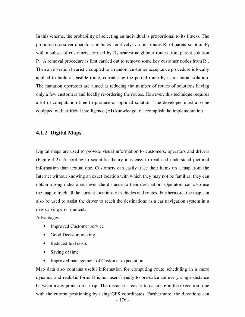
- 176 -
In this scheme, the probability of selecting an individual is proportional to its fitness. The
proposed crossover operator combines iteratively, various routes R1 of parent solution P1
with a subset of customers, formed by R2 nearest-neighbour routes from parent solution
P2. A removal procedure is first carried out to remove some key customer nodes from R1.
Then an insertion heuristic coupled to a random customer acceptance procedure is locally
applied to build a feasible route, considering the partial route R1 as an initial solution.
The mutation operators are aimed at reducing the number of routes of solutions having
only a few customers and locally re-ordering the routes. However, this technique requires
a lot of computation time to produce an optimal solution. The developer must also be
equipped with artificial intelligence (AI) knowledge to accomplish the implementation.
4.1.2 Digital Maps
Digital maps are used to provide visual information to customers, operators and drivers
(Figure 4.2). According to scientific theory it is easy to read and understand pictorial
information than textual one. Customers can easily trace their items on a map from the
Internet without knowing an exact location with which they may not be familiar; they can
obtain a rough idea about even the distance to their destination. Operators can also use
the map to track all the current locations of vehicles and routes. Furthermore, the map can
also be used to assist the driver to reach the destinations as a car navigation system in a
new driving environment.
Advantages:
• Improved Customer service
• Good Decision making
• Reduced fuel costs
• Saving of time
• Improved management of Customer expectation.
Map data also contains useful information for computing route scheduling in a more
dynamic and realistic form. It is not user-friendly to pre-calculate every single distance
between many points on a map. The distance is easier to calculate in the execution time
with the current positioning by using GPS coordinates. Furthermore, the directions can

- 177 -
also be indicated. A digital map aids in the completion of a schedule. It provides an
efficient and high quality service for the transport industry.
Figure 4.2 Screen shot of Sydney digital map.
4.1.2.1 OpenMap
OpenMap has been widely used in different projects, and is used to manipulate and
display maps in this project. Its ease of use and multi-functionality can be utilized to
create a component and display a digital map from different sources to the screen.
Figure 4.3 an overview of OpenMap architecture [5].
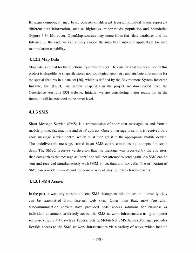
- 178 -
Its main component, map bean, consists of different layers; individual layers represent
different data information, such as highways, minor roads, population and boundaries
(Figure 4.3). Moreover, OpenMap sources may come from flat files, databases and the
Internet. In the end, we can simply embed the map bean into our application for map
manipulation capability.
4.1.2.2 Map Data
Map data is crucial for the functionality of this project. The data file that has been used in this
project is shapefile. A shapefile stores non-topological geometry and attribute information for
the spatial features in a data set [36], which is defined by the Environment System Research
Institute, Inc. (ESRI). All sample shapefiles in the project are downloaded from the
Geoscience Australia [35] website. Initially, we are considering major roads, but in the
future, it will be extended to the street level.
4.1.3 SMS
Short Message Service (SMS) is a transmission of short text messages to and from a
mobile phone, fax machine and or IP address. Once a message is sent, it is received by a
short message service centre, which must then get it to the appropriate mobile device.
The undeliverable message, stored in an SMS centre continues its attempts for seven
days. The SMSC receives verification that the message was received by the end user,
then categorizes the message as "sent" and will not attempt to send again. An SMS can be
sent and received simultaneously with GSM voice, data and fax calls. The utilization of
SMS can provide a simple and convenient way of staying in touch with drivers.
4.1.3.1 SMS Access
In the past, it was only possible to send SMS through mobile phones, but currently, they
can be transmitted from Internet web sites. Other than that, most Australian
telecommunication carriers have provided SMS access solutions for business or
individual customers to directly access the SMS network infrastructure using computer
software (Figure 4.4), such as Telstra. Telstra MobileNet SMS Access Manager provides
flexible access to the SMS network infrastructure via a variety of ways, which include
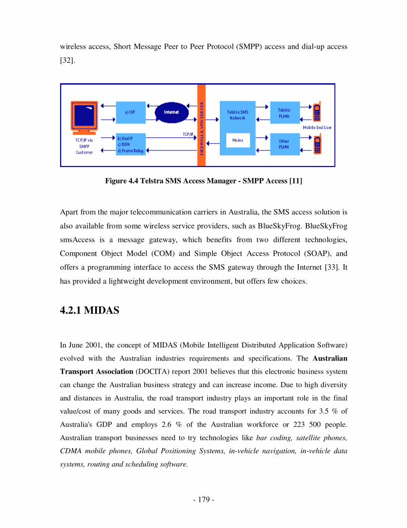
- 179 -
wireless access, Short Message Peer to Peer Protocol (SMPP) access and dial-up access
[32].
Figure 4.4 Telstra SMS Access Manager - SMPP Access [11]
Apart from the major telecommunication carriers in Australia, the SMS access solution is
also available from some wireless service providers, such as BlueSkyFrog. BlueSkyFrog
smsAccess is a message gateway, which benefits from two different technologies,
Component Object Model (COM) and Simple Object Access Protocol (SOAP), and
offers a programming interface to access the SMS gateway through the Internet [33]. It
has provided a lightweight development environment, but offers few choices.
4.2.1 MIDAS
In June 2001, the concept of MIDAS (Mobile Intelligent Distributed Application Software)
evolved with the Australian industries requirements and specifications. The Australian
Transport Association (DOCITA) report 2001 believes that this electronic business system
can change the Australian business strategy and can increase income. Due to high diversity
and distances in Australia, the road transport industry plays an important role in the final
value/cost of many goods and services. The road transport industry accounts for 3.5 % of
Australia's GDP and employs 2.6 % of the Australian workforce or 223 500 people.
Australian transport businesses need to try technologies like bar coding, satellite phones,
CDMA mobile phones, Global Positioning Systems, in-vehicle navigation, in-vehicle data
systems, routing and scheduling software.
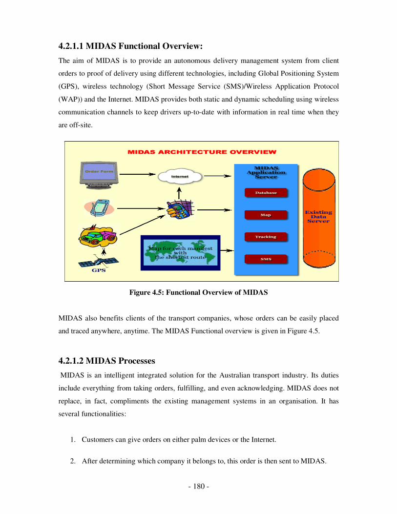
- 180 -
4.2.1.1 MIDAS Functional Overview:
The aim of MIDAS is to provide an autonomous delivery management system from client
orders to proof of delivery using different technologies, including Global Positioning System
(GPS), wireless technology (Short Message Service (SMS)/Wireless Application Protocol
(WAP)) and the Internet. MIDAS provides both static and dynamic scheduling using wireless
communication channels to keep drivers up-to-date with information in real time when they
are off-site.
Figure 4.5: Functional Overview of MIDAS
MIDAS also benefits clients of the transport companies, whose orders can be easily placed
and traced anywhere, anytime. The MIDAS Functional overview is given in Figure 4.5.
4.2.1.2 MIDAS Processes
MIDAS is an intelligent integrated solution for the Australian transport industry. Its duties
include everything from taking orders, fulfilling, and even acknowledging. MIDAS does not
replace, in fact, compliments the existing management systems in an organisation. It has
several functionalities:
1. Customers can give orders on either palm devices or the Internet.
2. After determining which company it belongs to, this order is then sent to MIDAS.
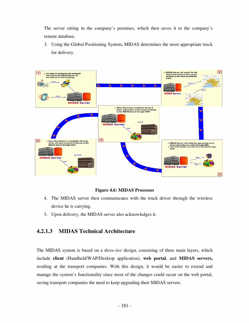
- 181 -
The server sitting in the company’s premises, which then saves it to the company’s
remote database.
3. Using the Global Positioning System, MIDAS determines the most appropriate truck
for delivery.
Figure 4.6: MIDAS Processes
4. The MIDAS server then communicates with the truck driver through the wireless
device he is carrying.
5. Upon delivery, the MIDAS server also acknowledges it.
4.2.1.3 MIDAS Technical Architecture
The MIDAS system is based on a three-tier design, consisting of three main layers, which
include client (Handheld/WAP/Desktop application), web portal, and MIDAS servers,
residing at the transport companies. With this design, it would be easier to extend and
manage the system’s functionality since most of the changes could occur on the web portal,
saving transport companies the need to keep upgrading their MIDAS servers.
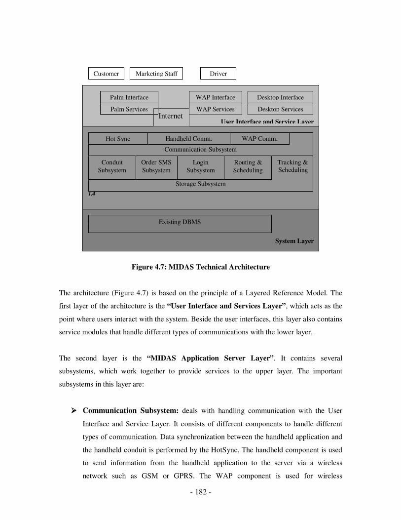
- 182 -
Figure 4.7: MIDAS Technical Architecture
The architecture (Figure 4.7) is based on the principle of a Layered Reference Model. The
first layer of the architecture is the “User Interface and Services Layer”, which acts as the
point where users interact with the system. Beside the user interfaces, this layer also contains
service modules that handle different types of communications with the lower layer.
The second layer is the “MIDAS Application Server Layer”. It contains several
subsystems, which work together to provide services to the upper layer. The important
subsystems in this layer are:
���� Communication Subsystem: deals with handling communication with the User
Interface and Service Layer. It consists of different components to handle different
types of communication. Data synchronization between the handheld application and
the handheld conduit is performed by the HotSync. The handheld component is used
to send information from the handheld application to the server via a wireless
network such as GSM or GPRS. The WAP component is used for wireless
Customer Marketing Staff Driver
User Interface and Service Layer
Palm Interface
Palm Services
WAP Interface
WAP Services
Desktop Interface
Desktop Services
1.1
1.2
1.3
1.4
MIDAS Software System Layer
Tracking &
Scheduling
Storage Subsystem
Communication Subsystem
Hot Sync Handheld Comm. WAP Comm.
Order SMS
Subsystem
Login
Subsystem
Routing &
Scheduling
Conduit
Subsystem
1.4.1.1
System Layer
Existing DBMS
Internet
- 183 -
communication between the WAP application and the server. This subsystem is very
important since it is the core of the whole system.
���� Conduit Subsystem: The prime responsibility of this subsystem is to manage the
correct data synchronization between the handheld device and desktop computer.
During the synchronization, the subsystem also needs to perform data conversion
from handheld data format into desktop data format. The synchronization logic
applied by this subsystem is summarized in table 3.2.
���� Order Subsystem: The subsystem will be part of the MIDAS server, which resides
at the transport companies. It is responsible for handling all requests that are related
to orders, such as accepting new orders, and calculating order invoices.
���� Routing and Scheduling Subsystem: In any transport company satisfaction
between client/customer and operating costs are the most important factors. This
subsystem is responsible of the dynamic routing and scheduling of the daily run sheet
of drivers. Dynamic scheduling has simplified transport logistics such as courier
services, by providing technology-enhanced, real-time communication. Service
requests from the same area should be served once rather than multiple times,
facilitating a huge saving in travel distance and time.
���� Login Subsystem: This subsystem is responsible for maintaining users’ accounts
and handling the authentication of requests from handheld applications and WAP
applications. This module will be part of the web portal.
���� Storage Subsystem: This is responsible for providing a means for storage, such
as connection to existing DBMS and file management. Queries on the database
depend upon this subsystem. By having this subsystem, changes to storage will
not affect any of the other subsystems, thus improving system flexibility.
The last layer of this architecture is the “System Layer”. It represents the existing
company’s system environment, which includes the company’s DBMS and Operating
System.
- 184 -
4.2.1.4 MIDAS modules:
MIDAS consists of three different modules: - Internet module, MIDAS Server Module and
lastly, Wireless module, each have different key responsibilities.
1. Accepting orders, communicating with remote company’s server and transferring data in
XML format are key responsibilities of the Internet module. This module also provides a
generic Internet based transport exchange, which invites many customers from different
companies, log in and give an order. For each of these customers, a personalized profile is
stored.
2. Secondly, the MIDAS Server module accepts the XML based order from the Internet and
Palm, and stores it on the company’s database. Finding the appropriate truck through GPS
and sending the SMS messages to drivers are included in its task list. Routing and Scheduling
is another important part of this module. It provides dynamic routing for each run sheet of a
driver at a run time.
3. Thirdly, the Wireless module, which allows the customer to give an order, which is then
accepted by MIDAS server. This module also accepts proof of delivery and docket transfers.
4.2.2 MIDAS Server
The MIDAS server resides in the company’s remote server and is the heart of the system.
It performs a lot of core tasks, such tracking drivers, trucks and routes, finding the closest
truck with time constraints, sending SMS messages to the drivers, and rescheduling the
manifest. Some of the key functionalities are classified into External and Internal
Functionalities.
External Functionalities: External Functionalities of the MIDAS server include Accepting
order, Checking Balances, Registration Validations, Check booking and Acknowledging
order completion.
Internal Functionalities: Internal Functionalities include Path searching, Scheduling,
Mapping, SMS and Database Connectivity.
- 185 -
4.2.2.1. Specification
This chapter will also specify the objectives, constraints and requirements of the system. It
includes the statements of the functional and non-functional requirements. Performance and
maintainability issues will then be considered. These requirements specify the quantity and
quality of the application.
o Objectives
The main objective of the MIDAS server system is to provide an autonomous dynamic route
scheduling system that enables scheduling of transport industry orders in two manners: static
and dynamic. Furthermore, the sub-goals of MIDAS need to be accomplished as follows:
Order System accepts a new order from any means, either from a palm device or from the
Internet server, and saves it onto a database. The Intelligent system determines the day of
delivery; if it is the same day, then acknowledgement should be sent to the driver. The
Scheduling System produces optimal routes for the order. Finally, the Digital Map system
shows the current position of the truck and the route.
o Constraints
i. An important requirement is to have a device which can tell the current position of all
the vehicles. However, this is not possible and we assume that the GPS data is already
saved in the database.
ii. The meaning of the current position of vehicles on longitude and latitude values have to
be interpreted by maps. Unfortunately, the commercial value of Australian map data costs
over $A28,000 a year. This is quite expensive, so we are using free map data, which
covers major roads and locality names.
iii. Although this project is developed in the Java computer language, the database uses
Microsoft Access as a back end. Therefore, the complete working version requires a
Windows platform. Otherwise, database migration is required.
o Specific Requirements
This section identifies the actual work that needs to be implemented in the system. In order to
develop a system in a manageable way; it must provide much more detail on what to do and
what is needed for the intended system.

- 186 -
� Functional Requirements
The functional requirements state the quantity of the application that needs to be developed.
It specifies the operational functionalities of the system.
I. MIDAS Server External Functional Requirements
a) Accept order: To accept order through palm device or Internet server in XML format
and the output would be in Order number
b) Check balance: To accept an invoice balance, checking the request from a Palm
device or Internet server in XML format, and producing the output will be an invoice
amount.
c) Register validation: Validating a customer of the transport company for the Internet
server by checking the Australian Business Number and customer code in XML
format. The result will be either ‘yes’ or ‘no’.
d) Check booking: checking the booking details by booking number using WAP phone.
The result will be sender and receiver details.
e) Acknowledge order completion: Upon completion, the server must be able to accept
an order completion notification using order number in XML format. The result will
be either true or false.
II. MIDAS Server Internal Functional Requirements
a) Path searching: To find the optimal path between two locations. The input we
provide is two locations and the result is an optimal path.
b) Scheduling: To schedule the existing orders, we provide the vehicle list and order list
as the input and the result is new schedule for the database.
c) Mapping: MIDAS server must be able to access map data from a Shape file and
perform mapping. The resultant is searchable data structure.
d) SMS: Other responsibilities include SMS via Internet or mobile.
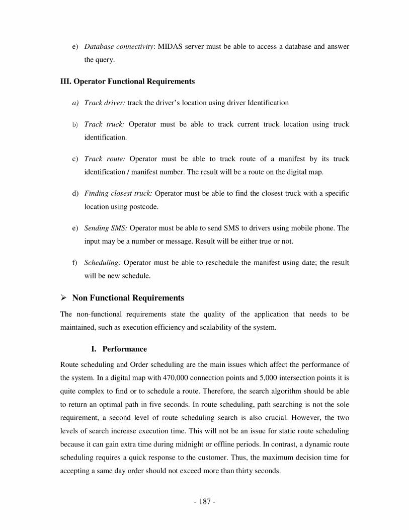
- 187 -
e) Database connectivity: MIDAS server must be able to access a database and answer
the query.
III. Operator Functional Requirements
a) Track driver: track the driver’s location using driver Identification
b) Track truck: Operator must be able to track current truck location using truck
identification.
c) Track route: Operator must be able to track route of a manifest by its truck
identification / manifest number. The result will be a route on the digital map.
d) Finding closest truck: Operator must be able to find the closest truck with a specific
location using postcode.
e) Sending SMS: Operator must be able to send SMS to drivers using mobile phone. The
input may be a number or message. Result will be either true or not.
f) Scheduling: Operator must be able to reschedule the manifest using date; the result
will be new schedule.
� Non Functional Requirements
The non-functional requirements state the quality of the application that needs to be
maintained, such as execution efficiency and scalability of the system.
I. Performance
Route scheduling and Order scheduling are the main issues which affect the performance of
the system. In a digital map with 470,000 connection points and 5,000 intersection points it is
quite complex to find or to schedule a route. Therefore, the search algorithm should be able
to return an optimal path in five seconds. In route scheduling, path searching is not the sole
requirement, a second level of route scheduling search is also crucial. However, the two
levels of search increase execution time. This will not be an issue for static route scheduling
because it can gain extra time during midnight or offline periods. In contrast, a dynamic route
scheduling requires a quick response to the customer. Thus, the maximum decision time for
accepting a same day order should not exceed more than thirty seconds.
- 188 -
II. Maintainability
The MIDAS server is developed to be compatible and cooperate with existing operational
systems that are used by transport companies. Route scheduling is a core component of the
MIDAS server. In terms of adaptability, the MIDAS server should be able to integrate with
any existing system without any major transformation. Thus, it should be easily able to plug
in a new algorithm without components modification. The MIDAS server is a central
communication hub that resides in a transport company. It establishes the communication
channels with the other two components of the MIDAS, Internet server and mobile devices,
for internal systems. Hence, interoperability communication is an elemental requirement for
the cooperation of the MIDAS server and other components.
4.2.2.2 Design
Besides the specifications, design is another major step to ensure a high quality of
applications in software engineering. This chapter illustrates the design of our system from
various diagrams by the Unified Modelling Language (UML), which include use cases,
class diagrams, sequences diagrams and state diagrams. These diagrams identify the
satisfaction of requirements from the design approach from the previous chapter.
Furthermore, these diagrams also describe the system development semantics in Object-
Oriented Language.
a) Use Cases
Figure 4.8 illustrates the interaction between the MIDAS server and MIDAS external entries.
It identifies the system activities and user actions, which needs to be performed by the
MIDAS server from the functional requirements. The necessary components can be identified
to carry out these activities. External entries include the Internet, Palm and WAP devices and
system operators. Activities between the MIDAS server and the Internet/Palm devices
include ordering, balance checking and register validating.
These major activities invoke database connectivity to perform saving or retrieving data
records from the back-end database. Ordering will also invoke route scheduling with routing
and mapping to obtain an appropriate vehicle to fulfil an emergency order and then inform
the vehicle driver through the SMS module.

- 189 -
order
check balance
Internet
register validation
Palm
check booking
order acknowledgement
WAP
routing
route scheduling
mapping
database connectivity
SMS
find closest truck
send SMS
track route
track truck
track driver
schedule
System Operator
<<include>>
<<extend>>
<<include>>
<<include>>
<<include>>
<<include>>
<<include>>
<<include>>
<<include>>
<<extend>>
<<extend>>
<<extend>>
<<include>>
<<extend>>
<<extend>>
Figure 4.8 Interaction between MIDAS and MIDAS external entities.
� The activities between the MIDAS server and WAP devices include booking
checking and order acknowledgement. They will directly invoke database
connectivity to perform checking and acknowledge recording.
� The activities between the MIDAS server and system operators include several
comprehensive tasks; sending SMS, scheduling, finding the closest truck, performing
truck and driver tracking, and route tracking.
All tracking is done using the mapping procedure. The task of finding the closest truck
invokes routing and mapping to accomplish a reality road network based search. The
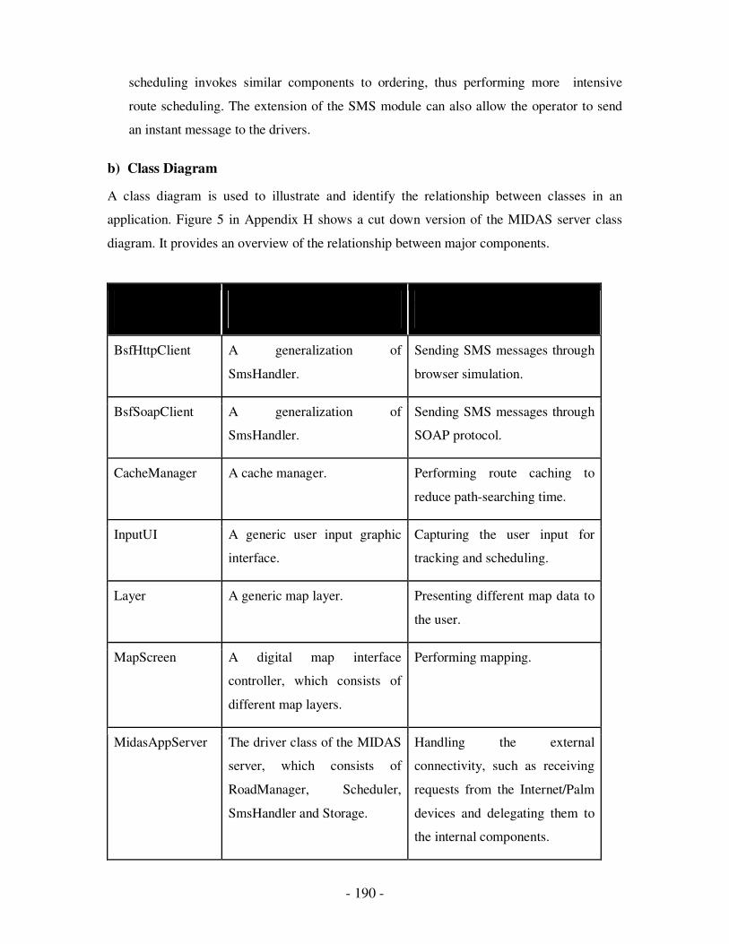
- 190 -
scheduling invokes similar components to ordering, thus performing more intensive
route scheduling. The extension of the SMS module can also allow the operator to send
an instant message to the drivers.
b) Class Diagram
A class diagram is used to illustrate and identify the relationship between classes in an
application. Figure 5 in Appendix H shows a cut down version of the MIDAS server class
diagram. It provides an overview of the relationship between major components.
Class Name Class description Tasks Performed
BsfHttpClient A generalization of
SmsHandler.
Sending SMS messages through
browser simulation.
BsfSoapClient A generalization of
SmsHandler.
Sending SMS messages through
SOAP protocol.
CacheManager A cache manager. Performing route caching to
reduce path-searching time.
InputUI A generic user input graphic
interface.
Capturing the user input for
tracking and scheduling.
Layer A generic map layer. Presenting different map data to
the user.
MapScreen A digital map interface
controller, which consists of
different map layers.
Performing mapping.
MidasAppServer The driver class of the MIDAS
server, which consists of
RoadManager, Scheduler,
SmsHandler and Storage.
Handling the external
connectivity, such as receiving
requests from the Internet/Palm
devices and delegating them to
the internal components.
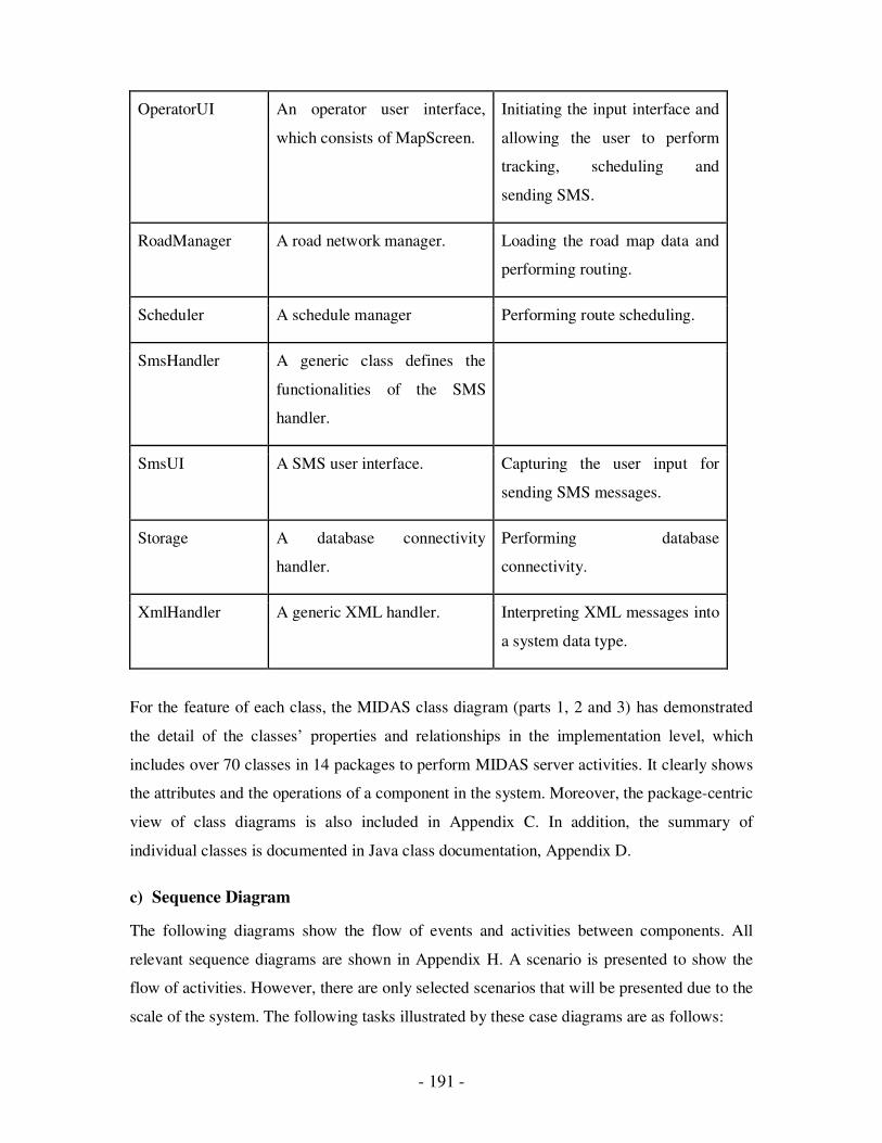
- 191 -
OperatorUI An operator user interface,
which consists of MapScreen.
Initiating the input interface and
allowing the user to perform
tracking, scheduling and
sending SMS.
RoadManager A road network manager. Loading the road map data and
performing routing.
Scheduler A schedule manager Performing route scheduling.
SmsHandler A generic class defines the
functionalities of the SMS
handler.
SmsUI A SMS user interface. Capturing the user input for
sending SMS messages.
Storage A database connectivity
handler.
Performing database
connectivity.
XmlHandler A generic XML handler. Interpreting XML messages into
a system data type.
For the feature of each class, the MIDAS class diagram (parts 1, 2 and 3) has demonstrated
the detail of the classes’ properties and relationships in the implementation level, which
includes over 70 classes in 14 packages to perform MIDAS server activities. It clearly shows
the attributes and the operations of a component in the system. Moreover, the package-centric
view of class diagrams is also included in Appendix C. In addition, the summary of
individual classes is documented in Java class documentation, Appendix D.
c) Sequence Diagram
The following diagrams show the flow of events and activities between components. All
relevant sequence diagrams are shown in Appendix H. A scenario is presented to show the
flow of activities. However, there are only selected scenarios that will be presented due to the
scale of the system. The following tasks illustrated by these case diagrams are as follows:
- 192 -
� Sequence Diagram for Palm ordering
Scenario: A new order is received from a Palm device. The order must be completed on
the same day. An appropriate driver has been tracked and SMS is sent to him. Refer to
Figure 2 in Appendix H.
Sequence:
When a new order is received by the MidassAppServer, the XML encoded message will
be parsed by using the XML parser with the XmlOrderHandler. So, the order
information can be obtained and passed to Storage. During the order saving process, the
Storage has to determine the emergency of the order. If the order must be completed on
the same day, the RecordListener will be informed and a new booking number will be
returned. The RecordListener determines an appropriate truck and notifies the
OperatorUI. Then, the SMS message is sent through the SmsHandler. Also, the booking
number is encoded in XML format and sent back to the sender.
� Sequence Diagram for Retrieving Booking Detail
Scenario: A WAP user retrieves a booking detail through the Internet server. The
booking/order number already exists in the database. Refer to Figure 3 in Appendix H.
Sequence:
When a request is received by the MidassAppServer, the XML encoded message will be
parsed by using the XML parser with the XmlBookingHandler. Therefore, the booking
number can be obtained and used to retrieve the detail of the booking from the Storage.
Then, the booking detail is encoded in XML format and sent back to the sender.
� Sequence Diagram for Route Tracking
Scenario: The system operator inputs a truck number for route tracking. A specific route
is rendered to the screen with the digital map. Refer to Figure 4 in Appendix H.
Sequence:
When the OperatorUI receives the action event from the system operator, an InputUI
will be created and displayed. This allows the user to enter the truck identification.
Then, the entered information is passed onto OpMap, which then retrieves the current
location of the truck and service locations from the Storage. Next, the route is
- 193 -
constructed by RoadManage with the location information. Finally, the truck location,
service locations and route information are added to different map data handlers,
including VehicleDataHandler, CustomerDataHandler and RouteDataHandler, which
handle mapping data during display to the user.
� Sequence Diagram for Truck Tracking
Scenario: The system operator inputs a truck number for truck tracking. Refer to Figure
5 in Appendix H.
Sequence:
When the OperatorUI receives the action event from the system operator, an InputUI
will be created and displayed. It allows the user to enter the truck identification. Then,
the entered information is passed onto the OpMap. The OpMap retrieves the current
location of the truck and its locality from the Storage. Next, the truck location and the
relevant information is added to VehicleDataHandler and LabelDataHandler, which
handle mapping data during display to the user.
� Sequence Diagram for Scheduling
Scenario: The system operator inputs a scheduling date, which is saved to the database.
Refer to Figure 6 in Appendix H.
Sequence:
When the OperatorUI receives the action event from the system operator, an InputUI
will be created and displayed, allowing the user to enter the scheduling date. This is then
passed onto the Scheduler, which retrieves the vehicles and booking information from
the Storage. Finally, this information is forwarded to the Algorithm to perform
scheduling, which also invokes the Road Manager to obtain route information.
At the end of the scheduling, the Algorithm returns the Search Result object that
contains the scheduled routes. The Scheduler saves routes to the database via the
Storage.
- 194 -
d) State Diagrams
The state diagram extends the event and activities occurrences from an external point of view
into an internal point of view of individual components. It illustrates the internal state
changes for further understanding of task performances in each component. In this section, it
will only cover the state diagram of the system’s main component, namely routing and
scheduling.
� Activity Diagram for Routing
This diagram illustrates the activity states during routing in RoadManager component. It
provides a graphical pseud-code description of the path-searching algorithm. Refer to Figure
7 in Appendix H.
• Activity Diagram for Scheduling
This diagram illustrates the activity states during scheduling in the Insertion component.
It provides a graphical pseudo-code description of the Insertion scheduling algorithm. Refer
to Figure 8 in Appendix H.
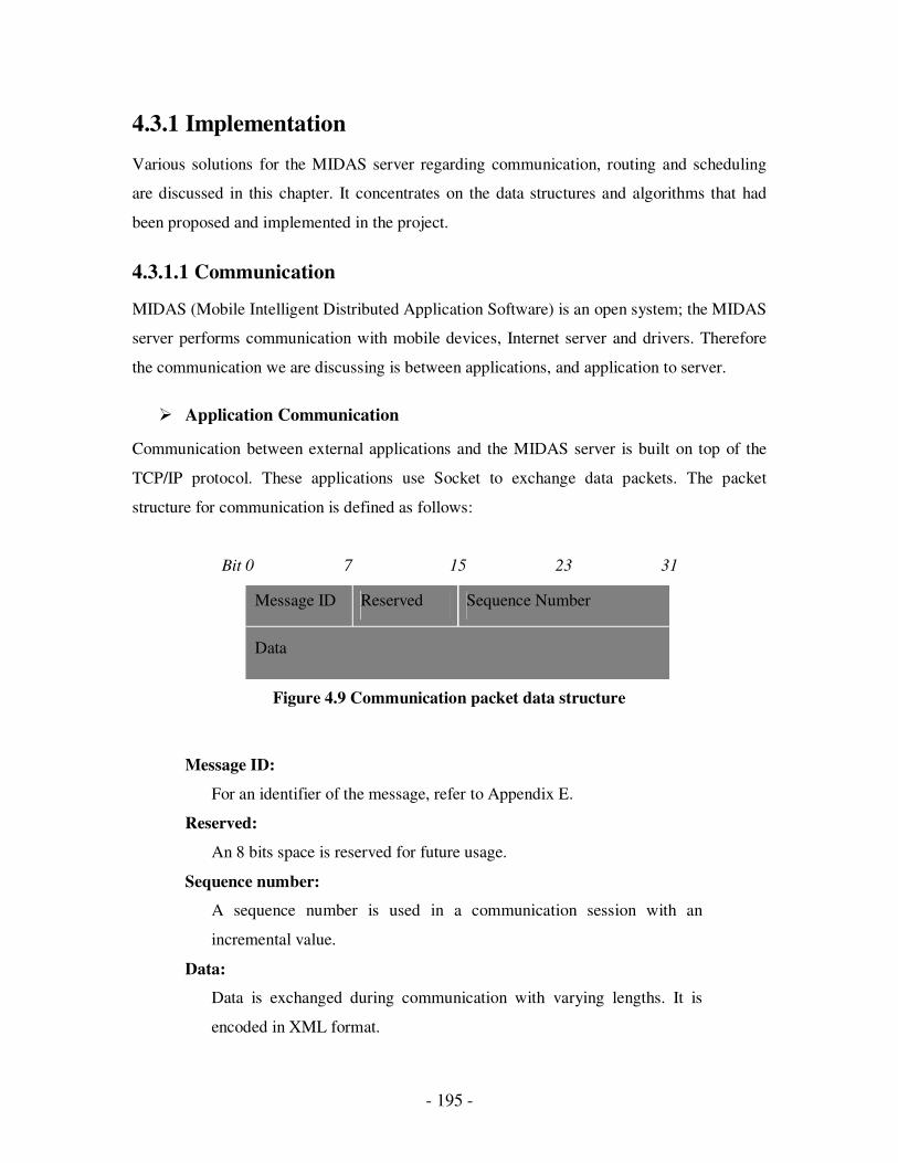
- 195 -
4.3.1 Implementation
Various solutions for the MIDAS server regarding communication, routing and scheduling
are discussed in this chapter. It concentrates on the data structures and algorithms that had
been proposed and implemented in the project.
4.3.1.1 Communication
MIDAS (Mobile Intelligent Distributed Application Software) is an open system; the MIDAS
server performs communication with mobile devices, Internet server and drivers. Therefore
the communication we are discussing is between applications, and application to server.
� Application Communication
Communication between external applications and the MIDAS server is built on top of the
TCP/IP protocol. These applications use Socket to exchange data packets. The packet
structure for communication is defined as follows:
Bit 0 7 15 23 31
Message ID Reserved Sequence Number
Data
Figure 4.9 Communication packet data structure
Message ID:
For an identifier of the message, refer to Appendix E.
Reserved:
An 8 bits space is reserved for future usage.
Sequence number:
A sequence number is used in a communication session with an
incremental value.
Data:
Data is exchanged during communication with varying lengths. It is
encoded in XML format.
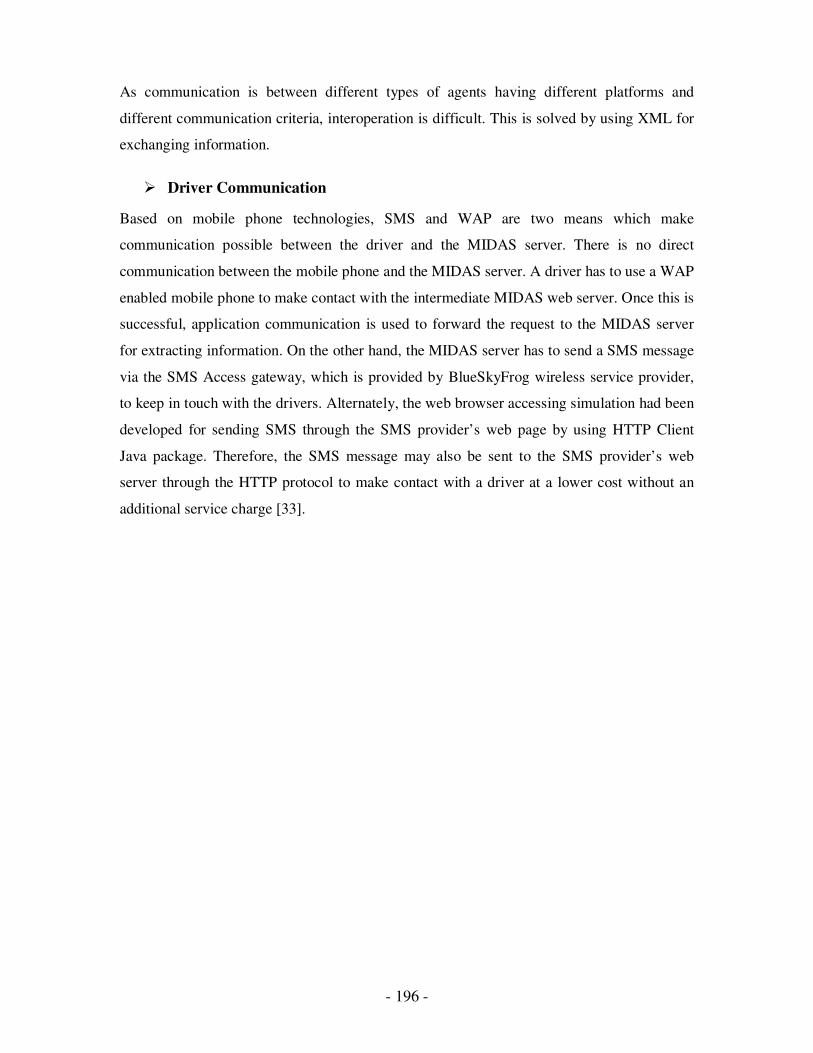
- 196 -
As communication is between different types of agents having different platforms and
different communication criteria, interoperation is difficult. This is solved by using XML for
exchanging information.
� Driver Communication
Based on mobile phone technologies, SMS and WAP are two means which make
communication possible between the driver and the MIDAS server. There is no direct
communication between the mobile phone and the MIDAS server. A driver has to use a WAP
enabled mobile phone to make contact with the intermediate MIDAS web server. Once this is
successful, application communication is used to forward the request to the MIDAS server
for extracting information. On the other hand, the MIDAS server has to send a SMS message
via the SMS Access gateway, which is provided by BlueSkyFrog wireless service provider,
to keep in touch with the drivers. Alternately, the web browser accessing simulation had been
developed for sending SMS through the SMS provider’s web page by using HTTP Client
Java package. Therefore, the SMS message may also be sent to the SMS provider’s web
server through the HTTP protocol to make contact with a driver at a lower cost without an
additional service charge [33].
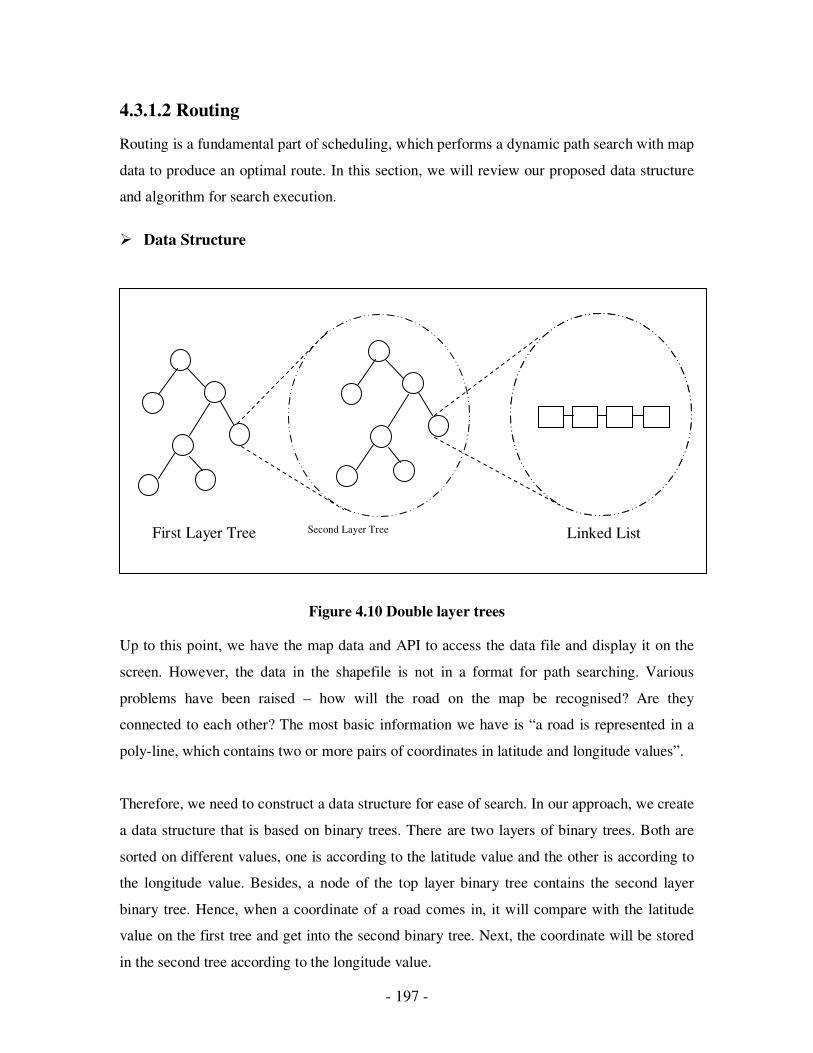
- 197 -
Linked List First Layer Tree Second Layer Tree
4.3.1.2 Routing
Routing is a fundamental part of scheduling, which performs a dynamic path search with map
data to produce an optimal route. In this section, we will review our proposed data structure
and algorithm for search execution.
� Data Structure
Figure 4.10 Double layer trees
Up to this point, we have the map data and API to access the data file and display it on the
screen. However, the data in the shapefile is not in a format for path searching. Various
problems have been raised – how will the road on the map be recognised? Are they
connected to each other? The most basic information we have is “a road is represented in a
poly-line, which contains two or more pairs of coordinates in latitude and longitude values”.
Therefore, we need to construct a data structure for ease of search. In our approach, we create
a data structure that is based on binary trees. There are two layers of binary trees. Both are
sorted on different values, one is according to the latitude value and the other is according to
the longitude value. Besides, a node of the top layer binary tree contains the second layer
binary tree. Hence, when a coordinate of a road comes in, it will compare with the latitude
value on the first tree and get into the second binary tree. Next, the coordinate will be stored
in the second tree according to the longitude value.

- 198 -
� Closest Point
Figure 4.11 Closest points nomination
However, these are the same coordinates that belong to two or more different roads because
of connections or intersections between them. Therefore, the nodes of the second tree allow
duplicate values to be stored for different roads. Therefore, a node of the second tree contains
a linked list and the final storage of the coordinates is the linked list, which will also link to
all the corresponding road information (Figure 4.10). This structure allows us to search an
entry according to two values (latitude and longitude) in log N complexity, where N is the
number of entries.
There are no restricted locations, so vehicles and customers can be anywhere on the map. A
virtual path needs to be established between a specific coordinate and a real road. Other than
that, the nearest road has to be selected for forming a real path based on the road network.
It is not possible to check every point on the road for shortest path testing, especially when
the area of the map is getting bigger. To overcome this, we utilize the characteristic of
- 199 -
coordinates and sort them using the above data structure. Then, we try to find a small range
of nominated coordinates, which are possibly next to the specific location. This approach can
also be used for searching the nearest vehicle with a given point. First of all, four nominated
coordinates can be selected based on four directions of the particular coordinate (a centre
point); the closest point from each of the four directions - North, East, South and West. From
these four points, we can form a rectangular area, which will cover all the points next to the
centre point. As all the points of rectangle are not regular, the rectangle can be very irregular.
The next step is to form a circular area by using the closest point out of all of them. We use
the distance between the closest and the centre point, as a radius to form the circle. As we
know, a circle has the same distance in all directions at any angle from the centre point;
hence, the covered points in this area are more representative for the nomination with shorter
distances. Furthermore, since the points in the area are much less than the whole map, the
number of direct distance comparisons can be reduced significantly; just use those points in
the nominated area for finding the nearest point (Figure 4.11). Hence, time can be saved from
comparing all the points. Unfortunately, the circle may still happen to cover all the points in
the worst case.
� Path Searching
A wise choice in the correct direction, while standing in front of an intersection, can save a
lot of unnecessary traversal for destination reaching. In our approach, we will store all the
nominated paths into a limited buffer list, which is sorted according to the approximate
distance to the destination, in ascending order.
A = an approximated distance
L = the actual path length have found
D = the direct distance from the path to the destination
A = αL + βD
Where α + β = 1, α >= 0, β >=0.
Therefore, the list will be resorted when a new branch is added, where the first path in the list
is always the shortest to the destination.

- 200 -
The algorithm for path searching is as follows:
A new list is started in both the left and right directions. Then, the new nominated paths are
constructed recursively from the extension of the existing shortest path in the list, by adding
its branches before the next intersection appears, and then storing back to the list. If the new
branch is leading away from the destination or the path length is increasing without leading
closer to the destination, it will be pushed down from the head of the list. Repeated execution
of this will gradually lead to the destination with the shortest path at the first element of the
list.
From this approach, we can ensure the path is going in the correct direction and heading to
the destination that will be selected. On the other hand, the limited size of the buffer will
evict the last element from the list when the buffer is full. This will eliminate an unnecessary
search of those branches leading in the opposite direction. In some cases, this also eliminates
the infinity search when there is no path connection between two points. Figure 4.12 is a
sample outcome of path searching from Werribee to Queenscliff and Anglesea.
Begin with the left path and right path of the starting point and store them into the
buffer list, which is sorted by approximate distance to the destination.
While (the list is not empty).
Current path = Get the first path of the list and remove it
If (the current path does not reach the destination) then
If (the path is not end) then
Reproduces the current path to new paths with its branches
and store them back to the list
Else
Ignore the path
End if
Else
Terminates the loop and the path is established.
End if
End while
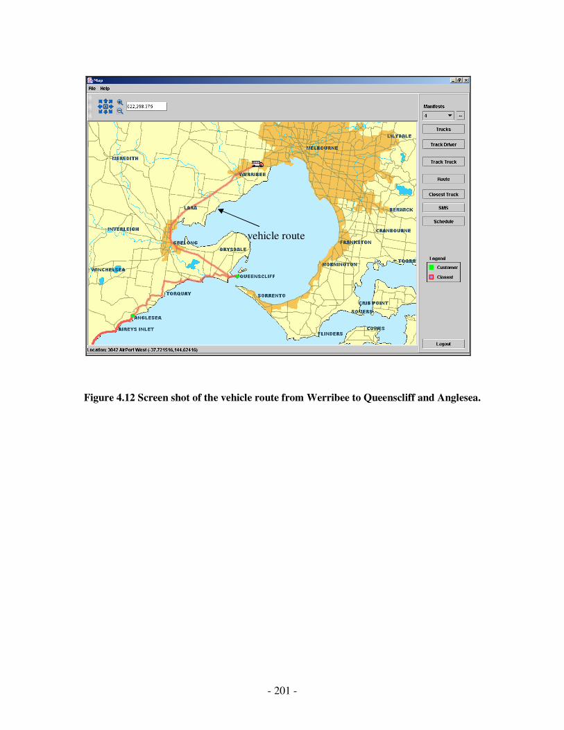
- 201 -
Figure 4.12 Screen shot of the vehicle route from Werribee to Queenscliff and Anglesea.
vehicle route

- 202 -
4.3.1.3 Scheduling
After routing, scheduling is a vital requirement for providing efficiency of transport or
logistics services. Scheduling performs the second level of search with time and load
constraints to produce an optimal route for the whole journey of vehicles.
Vehicle list
Order list
Route list
While (vehicle list and order list are not empty).
Route = get a vehicle route from the vehicle list.
While (the order list is not empty)
Order = get an order from the order list
For (insert the Order.pickup into the route with different position until the
end)
Check the time and load constraints
If (pickup can be done) then
Do the same procedure as pickup with the Order.delivery
For (start from behind the pickup until the end of the route)
Check the time constraints
If (the delivery is successful) then
Add the route to the route list
Remove the order from the order list
End if
End for
End if
End for
Reset the vehicle route to the best route from the route list
If (the route is full) then
Remove the vehicle from the list
Go to get another vehicle route
End if
End while
End while
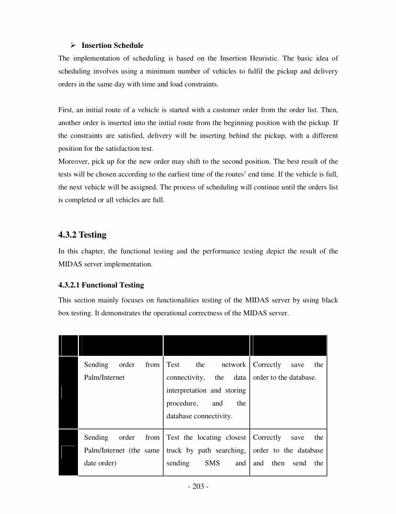
- 203 -
� Insertion Schedule
The implementation of scheduling is based on the Insertion Heuristic. The basic idea of
scheduling involves using a minimum number of vehicles to fulfil the pickup and delivery
orders in the same day with time and load constraints.
First, an initial route of a vehicle is started with a customer order from the order list. Then,
another order is inserted into the initial route from the beginning position with the pickup. If
the constraints are satisfied, delivery will be inserting behind the pickup, with a different
position for the satisfaction test.
Moreover, pick up for the new order may shift to the second position. The best result of the
tests will be chosen according to the earliest time of the routes’ end time. If the vehicle is full,
the next vehicle will be assigned. The process of scheduling will continue until the orders list
is completed or all vehicles are full.
4.3.2 Testing
In this chapter, the functional testing and the performance testing depict the result of the
MIDAS server implementation.
4.3.2.1 Functional Testing
This section mainly focuses on functionalities testing of the MIDAS server by using black
box testing. It demonstrates the operational correctness of the MIDAS server.
Test case Purpose Result
1.
Sending order from
Palm/Internet
Test the network
connectivity, the data
interpretation and storing
procedure, and the
database connectivity.
Correctly save the
order to the database.
2.
Sending order from
Palm/Internet (the same
date order)
Test the locating closest
truck by path searching,
sending SMS and
Correctly save the
order to the database
and then send the
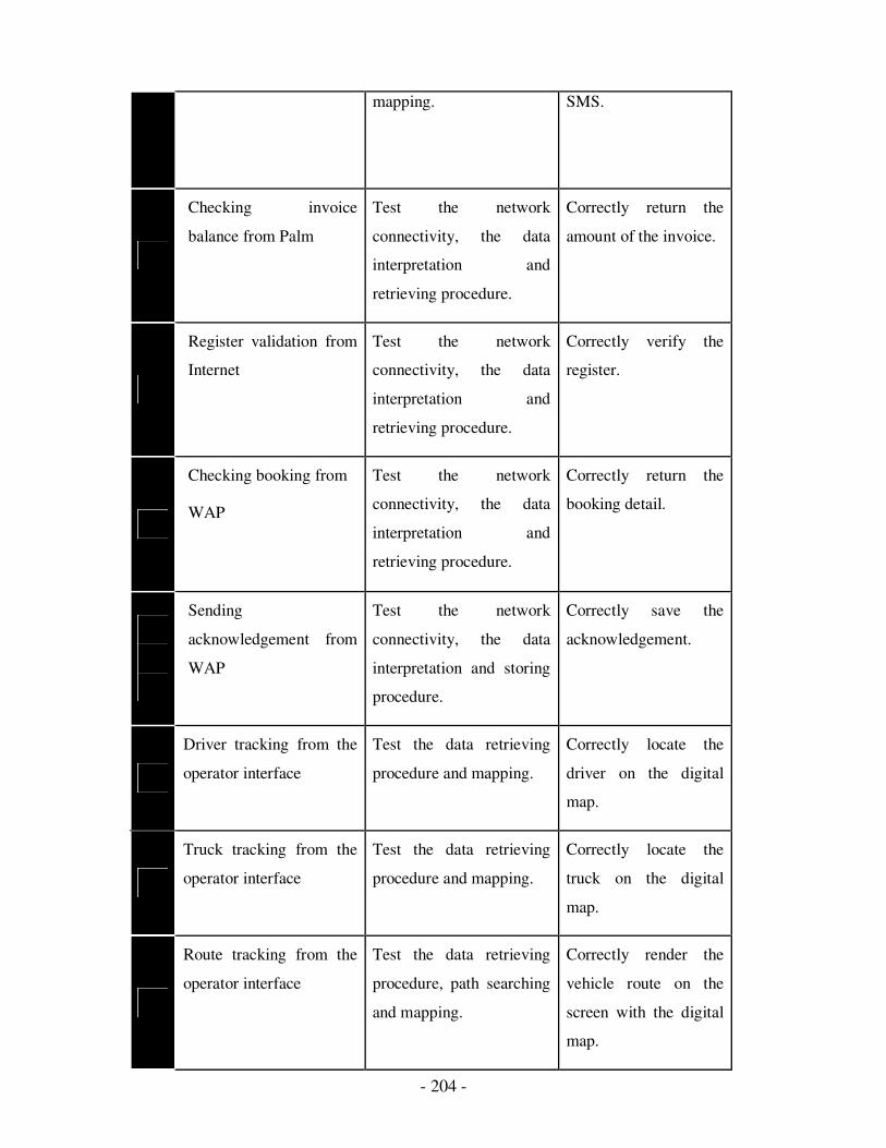
- 204 -
mapping. SMS.
3.
Checking invoice
balance from Palm
Test the network
connectivity, the data
interpretation and
retrieving procedure.
Correctly return the
amount of the invoice.
4.
Register validation from
Internet
Test the network
connectivity, the data
interpretation and
retrieving procedure.
Correctly verify the
register.
5.
Checking booking from
WAP
Test the network
connectivity, the data
interpretation and
retrieving procedure.
Correctly return the
booking detail.
Sending
acknowledgement from
WAP
Test the network
connectivity, the data
interpretation and storing
procedure.
Correctly save the
acknowledgement.
6.
Driver tracking from the
operator interface
Test the data retrieving
procedure and mapping.
Correctly locate the
driver on the digital
map.
7.
Truck tracking from the
operator interface
Test the data retrieving
procedure and mapping.
Correctly locate the
truck on the digital
map.
8.
Route tracking from the
operator interface
Test the data retrieving
procedure, path searching
and mapping.
Correctly render the
vehicle route on the
screen with the digital
map.
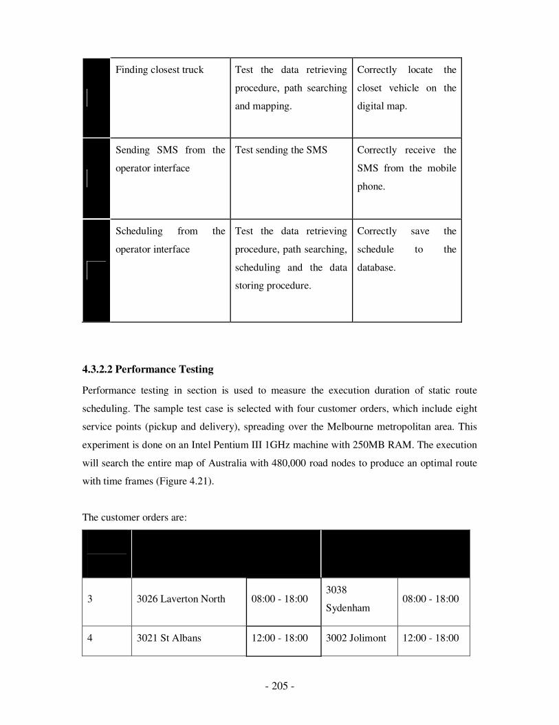
- 205 -
9.
Finding closest truck Test the data retrieving
procedure, path searching
and mapping.
Correctly locate the
closet vehicle on the
digital map.
10.
Sending SMS from the
operator interface
Test sending the SMS Correctly receive the
SMS from the mobile
phone.
11.
Scheduling from the
operator interface
Test the data retrieving
procedure, path searching,
scheduling and the data
storing procedure.
Correctly save the
schedule to the
database.
4.3.2.2 Performance Testing
Performance testing in section is used to measure the execution duration of static route
scheduling. The sample test case is selected with four customer orders, which include eight
service points (pickup and delivery), spreading over the Melbourne metropolitan area. This
experiment is done on an Intel Pentium III 1GHz machine with 250MB RAM. The execution
will search the entire map of Australia with 480,000 road nodes to produce an optimal route
with time frames (Figure 4.21).
The customer orders are:
Booking
No Pickup Delivery
3 3026 Laverton North 08:00 - 18:00 3038
Sydenham 08:00 - 18:00
4 3021 St Albans 12:00 - 18:00 3002 Jolimont 12:00 - 18:00
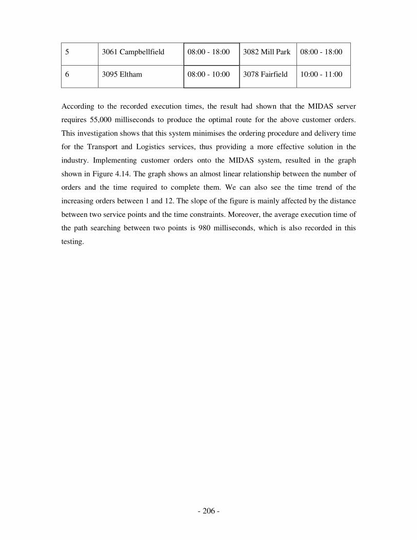
- 206 -
5 3061 Campbellfield 08:00 - 18:00 3082 Mill Park 08:00 - 18:00
6 3095 Eltham 08:00 - 10:00 3078 Fairfield 10:00 - 11:00
According to the recorded execution times, the result had shown that the MIDAS server
requires 55,000 milliseconds to produce the optimal route for the above customer orders.
This investigation shows that this system minimises the ordering procedure and delivery time
for the Transport and Logistics services, thus providing a more effective solution in the
industry. Implementing customer orders onto the MIDAS system, resulted in the graph
shown in Figure 4.14. The graph shows an almost linear relationship between the number of
orders and the time required to complete them. We can also see the time trend of the
increasing orders between 1 and 12. The slope of the figure is mainly affected by the distance
between two service points and the time constraints. Moreover, the average execution time of
the path searching between two points is 980 milliseconds, which is also recorded in this
testing.
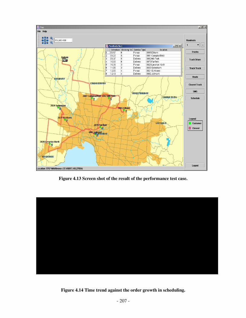
- 207 -
Figure 4.13 Screen shot of the result of the performance test case.
0
20000
40000
60000
80000
100000
120000
140000
160000
180000
200000
1 2 3 4 5 6 7 8 9 10 11 12
Time
Number of Orders
Figure 4.14 Time trend against the order growth in scheduling.
- 208 -
Thus far, the system has completely implemented route scheduling with the assistance of map
data and the Insertion Algorithm to perform a dynamic search.
In this chapter, we discussed communication in Routing and Scheduling. Even the best and
shortest possible path can be identified by using various algorithms and methods. The main
objective of this chapter is to discuss the various strategies to find the best routes and
schedule them according to the requirement to serve the customer as fast as possible.
The aim of this project was to analyze dynamic routing and scheduling in the Transport
Industry, using MIDAS, which the ARC Industry Grant (linkage) has specified. Use of the
Simple Object Access Protocol (SOAP) is a possible extension of the investigation presented
here.
In the next chapter we will see the placing of orders through the wireless devices which
reduce the service time for delivering order to the customer.

- 209 -
Chapter 5
ISSUE 4: Wireless Communication
Introduction:
This section will outline the work that was performed as part of the steps to build the MIDAS
system. The requirements described in this section are not the complete software
requirements for the MIDAS system, but only certain aspects that are relevant to the
discussion in this report. This section covers the stakeholders, system functional requirements
and non-functional requirements.
This chapter provides a detailed description of:
� The MIDAS architecture and design
� Various subsystems: Handheld Application design, Handheld Conduit Design,
Desktop Application Design, WAP Application and Design Implementation and
testing using different languages.
Sec 5.1 Related works
In this chapter we will discuss – how to identify the stakeholders? What are the functional
and non functional requirements?
5.1.1 Identification of stakeholders
A stakeholder is a person who has the interest in a project or in other words who will be
benefited by a project. In our project there are three stakeholders: MIDAS project manager,
the author and the Project supervisor.
� The MIDAS project manager – Once the project is complete, it will provide the
solution for the transport industry in an effective way.
� The author, who willl gain experience in the industry.
210
� The project supervisor – The supervisor is interested in the project because this will
provide an automated system with Internet and wireless communication for the
transport industry.
5.1.2 Functional requirements
This section describes the functional requirements of the MIDAS project. We will
concentrate on the requirements that are relevant to Mobile Computing. A major emphasis of
this project is on the careful design and communication between the client and its providers
via handheld devices and wireless network connection. The requirements are as follows:
5.1.2.1 Requirements for handheld application
� Input from the customer about the requirements and the demand of the product is
important.
� Message type and message number is the prime requirement when sending the
request. This will correctly determine the reply type and sequence number. After all
the required fields have been entered by the user, the application must be able to
generate XML data from the information and construct the request message header.
� The application must be able to retrieve the reply message header and parse the XML
data
� The new order details must be sent to the transport company through the web portal
by the application.
� In case of errors, the application must be capable of maintaining the order details e.g.
In communication or any server error condition.
The application must be able to send an invoice-checking request to the web portal,
which includes the booking number of an order.
� There should be dynamic listings to help the user fill in order details.
� The application must be able to let the user add new sender/receiver information for
faster access.
� The application must be able to maintain user information, which is needed during
communication with the web portal.
� The application must use the Palm database as storage instead of the traditional file.
- 211 -
� Before sending to the web portal, all user input must be validated. Validation is
performed according to the capability of the handheld device.
� The application must be able to detect a server error and parse the error.
5.1.2.2 Requirements for Handheld Conduit
The basic requirement of this module is to perform data synchronization between the
handheld device and a desktop computer. The most important part of this module is the
synchronization logic. The requirements include:
� Module must be able to convert the data structure between handheld device and
desktop correctly.
� The module must be able to determine the type of synchronization and select the
correct action to be performed.
� The module must be able to create a backup file after synchronization, as it is
important in case of failure.
5.1.2.3 Requirements for Desktop Application
The application data at the desktop computer is obtained through synchronization performed
by the handheld conduit. A basic requirement of this application is to display handheld
application data at the desktop computer. The requirements include:
� Application must be able to display synchronized information stored at the handheld
device.
5.1.2.4 Requirements for WAP Application
The requirement for this module is to send proof of delivery from the driver to the web portal
so that the company database will have the latest information regarding all orders.
� Before doing any operation, a user must enter the user name and password, which
must be checked against the appropriate database entry.
� Upon a successful login, drivers must have the ability to send proof of delivery to the
web portal
� Drivers must be able to view order details by providing the booking number.

212
5.1.3 Non-functional requirements
Non functional requirements are not essential to ensure system functionality, nonetheless, it
is desirable to have them.
5.1.3.1 Handheld application
� Handheld application should have the capability to prepare a history for the sent
orders for future use.
� The handheld device user should be able to add new product details into the palm
database.
� The handheld application should maintain a record for the last order sent to reduce
the amount of information to be stored.
5.1.3.2 Handheld Conduit
� The handheld conduit should do an appropriate log in.
� The integrity level should be high as a slight mistake can affect business transactions.
� There should be options for further expansion and growth of functionalities, as well
as users.
� The system must be easy to use without the need of any user manuals to perform
daily functions. Documentation for both users and developers should be kept for
future reference.
5.2 System Architecture and Design
We have discussed the MIDAS architecture in the chapter Routing and Scheduling in detail,
so an overview is provided. The MIDAS system is based on a three-tier design, where the
whole system can be segmented into three main layers, which include client
(Handheld/WAP/Desktop application), web portal, and MIDAS servers, residing at transport
companies. All changes occur on the web portal. Beside system extendibility, the use of the
3-tier approach will also make the management of the system easier; since the system can be
managed from one location, which is the web portal.
5.2.1 Overall system architecture
The architecture of the system is created based on the principle of a Layered Reference
Model – refer to Figure 4.7.
- 213 -
� The first layer of the architecture is the “User Interface and Services Layer”, which
acts as the point where the users interact with the system and communicate with the
lower layers.
� The second layer is the “MIDAS Application Server Layer”. This layer contains
several subsystems, which work together to provide services to the upper layer. The
important subsystems in this layer are:
� Communication Subsystem:
This subsystem is responsible for handling communication with the layer above (“User
Interface and Service Layer). The HotSync component is used to perform data
synchronization between the handheld application and the handheld conduit. The
handheld component is used to send information from the handheld application to the
server via a wireless network such as GSM or GPRS. The WAP component is used for
wireless communication between the WAP application and the server. This subsystem is
very important since it is the core of the system.
� Conduit Subsystem:
This subsystem is responsible for managing the data synchronization between the
handheld device and the desktop computer. This subsystem is responsible for data
synchronization to be performed correctly. During synchronization, the subsystem also
needs to perform data conversion from a handheld data format into a desktop data format.
� Order Subsystem:
This subsystem is responsible for handling all requests that are related to orders, such as
accepting new orders, and calculating order invoices. The subsystem will be part of the
MIDAS server, which resides at the transport companies.
214
� Driver Subsystem:
This subsystem is responsible for handling all requests that come from the drivers to the
server, such as updating proof of delivery and requesting order details. This module will
be part of the web portal.
� Login Subsystem:
This subsystem is responsible for maintaining user accounts and handling the
authentication of requests from handheld applications and WAP applications. This
module will be part of the web portal.
� Storage Subsystem:
This subsystem is responsible for providing a means for storage, such as connection to
existing DBMS and file management. All other subsystems depend on this system to
perform any queries to the database. By having this subsystem, changes to storage will
not affect any of the other subsystems, which improve system flexibility. This subsystem
is part of the MIDAS server, which resides at the transport companies.
The last layer of this architecture is the “System Layer” representing the existing company’s
system environment, which includes the company’s DBMS and Operating System.
5.2.2 Handheld application design
Customers use the handheld application to exchange information with the company servers
using wireless network connection. They are able to perform business transactions from
anywhere and at anytime. The Palm Powered handheld device has been selected as the
platform to implement this feature because it has been the most successful PDA in the
market, and it was developed with user usability and experience in mind. Moreover, it is easy
to deploy, with minimal training required for users. There have been a number of successful
implementations of Palm Powered PDA in the industries, including the transport industry.
It can be used to provide real-time information, access to email and scheduling applications,
and custom applications to take new orders.
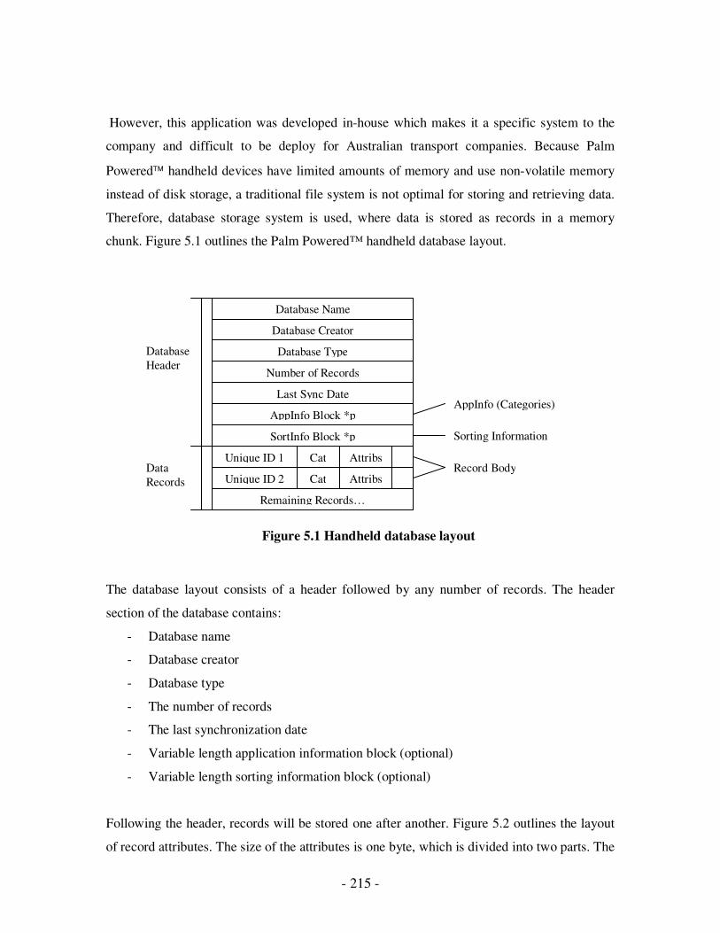
- 215 -
However, this application was developed in-house which makes it a specific system to the
company and difficult to be deploy for Australian transport companies. Because Palm
Powered handheld devices have limited amounts of memory and use non-volatile memory
instead of disk storage, a traditional file system is not optimal for storing and retrieving data.
Therefore, database storage system is used, where data is stored as records in a memory
chunk. Figure 5.1 outlines the Palm Powered™ handheld database layout.
Figure 5.1 Handheld database layout
The database layout consists of a header followed by any number of records. The header
section of the database contains:
- Database name
- Database creator
- Database type
- The number of records
- The last synchronization date
- Variable length application information block (optional)
- Variable length sorting information block (optional)
Following the header, records will be stored one after another. Figure 5.2 outlines the layout
of record attributes. The size of the attributes is one byte, which is divided into two parts. The
Data
Records
Database
Header
Database Name
Database Creator
Database Type
Number of Records
Last Sync Date
AppInfo Block *p
SortInfo Block *p
Unique ID 1 Cat Attribs
Remaining Records…
AppInfo (Categories)
Sorting Information
Record Body Unique ID 2 Cat Attribs
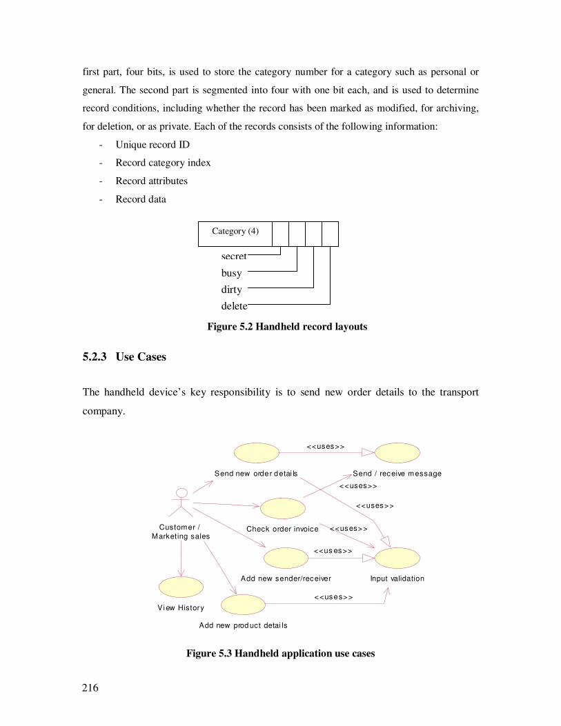
216
first part, four bits, is used to store the category number for a category such as personal or
general. The second part is segmented into four with one bit each, and is used to determine
record conditions, including whether the record has been marked as modified, for archiving,
for deletion, or as private. Each of the records consists of the following information:
- Unique record ID
- Record category index
- Record attributes
- Record data
Figure 5.2 Handheld record layouts
5.2.3 Use Cases
The handheld device’s key responsibility is to send new order details to the transport
company.
Figure 5.3 Handheld application use cases
Send new order detai ls
Add new sender/receiver
View History
Send / receive message
Check order invoice
<<uses>>
<<uses>>
Customer /
Marketing sales
Add new prod uct detai ls
Input validation
<<uses>>
<<us es>>
<<uses>>
<<uses>>
Category (4)
secret
busy
dirty
delete
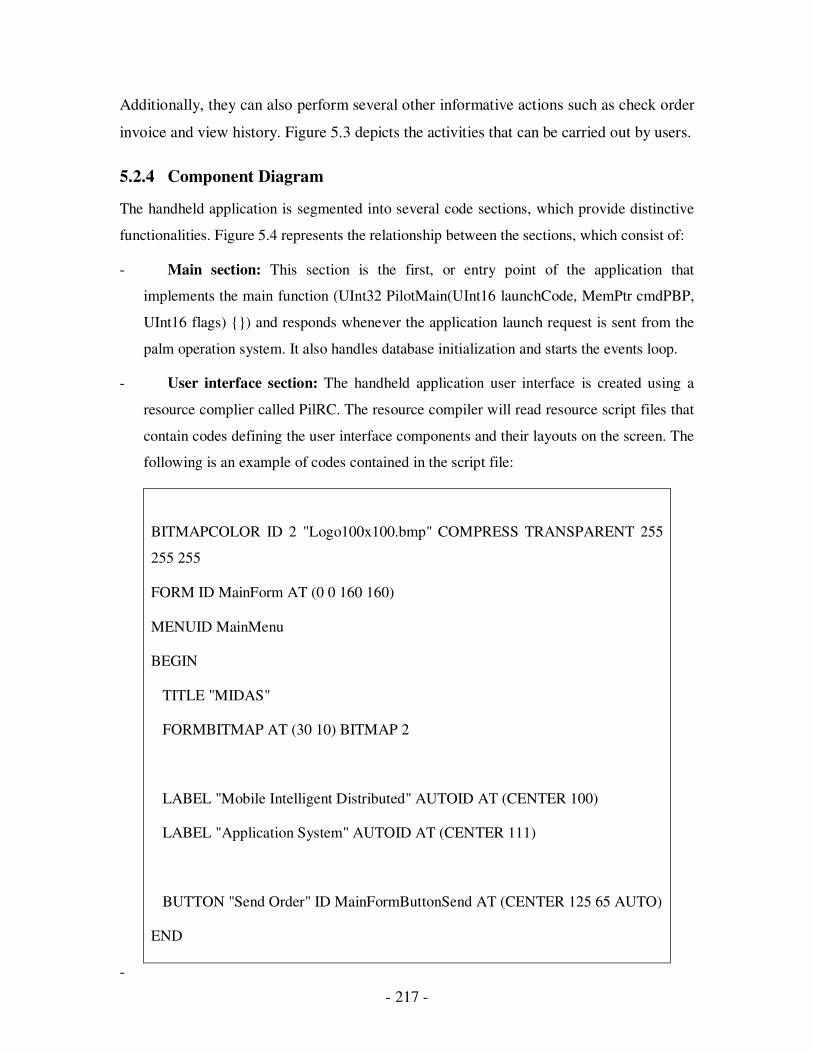
- 217 -
Additionally, they can also perform several other informative actions such as check order
invoice and view history. Figure 5.3 depicts the activities that can be carried out by users.
5.2.4 Component Diagram
The handheld application is segmented into several code sections, which provide distinctive
functionalities. Figure 5.4 represents the relationship between the sections, which consist of:
- Main section: This section is the first, or entry point of the application that
implements the main function (UInt32 PilotMain(UInt16 launchCode, MemPtr cmdPBP,
UInt16 flags) {}) and responds whenever the application launch request is sent from the
palm operation system. It also handles database initialization and starts the events loop.
- User interface section: The handheld application user interface is created using a
resource complier called PilRC. The resource compiler will read resource script files that
contain codes defining the user interface components and their layouts on the screen. The
following is an example of codes contained in the script file:
BITMAPCOLOR ID 2 "Logo100x100.bmp" COMPRESS TRANSPARENT 255
255 255
FORM ID MainForm AT (0 0 160 160)
MENUID MainMenu
BEGIN
TITLE "MIDAS"
FORMBITMAP AT (30 10) BITMAP 2
LABEL "Mobile Intelligent Distributed" AUTOID AT (CENTER 100)
LABEL "Application System" AUTOID AT (CENTER 111)
BUTTON "Send Order" ID MainFormButtonSend AT (CENTER 125 65 AUTO)
END
-
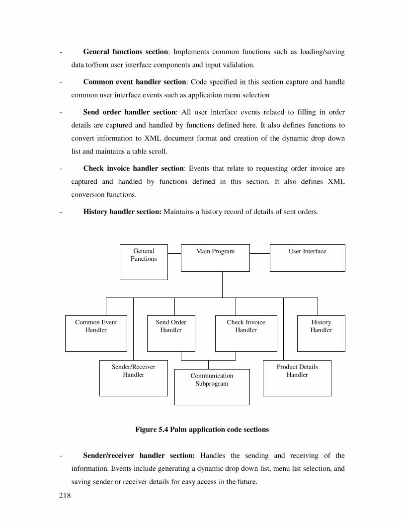
218
- General functions section: Implements common functions such as loading/saving
data to/from user interface components and input validation.
- Common event handler section: Code specified in this section capture and handle
common user interface events such as application menu selection
- Send order handler section: All user interface events related to filling in order
details are captured and handled by functions defined here. It also defines functions to
convert information to XML document format and creation of the dynamic drop down
list and maintains a table scroll.
- Check invoice handler section: Events that relate to requesting order invoice are
captured and handled by functions defined in this section. It also defines XML
conversion functions.
- History handler section: Maintains a history record of details of sent orders.
Figure 5.4 Palm application code sections
- Sender/receiver handler section: Handles the sending and receiving of the
information. Events include generating a dynamic drop down list, menu list selection, and
saving sender or receiver details for easy access in the future.
Main Program
Common Event
Handler
Communication
Subprogram
Sender/Receiver
Handler
General
Functions
Send Order
Handler
Product Details
Handler
User Interface
History
Handler
Check Invoice
Handler

- 219 -
- Product details handler section: Whenever a new product detail must be added or
captured, this section is active.
- Communication section: This section is responsible for managing information
exchange between the handheld application and the server. It provides network functions
such as locating and loading the network library, initializing and activating the socket
connection, and sending and receiving data.
5.2.5 Communication protocol and message format
Communication between the handheld devices and web portal will follow the protocol
defined in this section. The information that is sent between them will be formatted in XML
document format with the following Document Type Definition:
<?xml version=”1.0”?>
<!DOCTYPE order [
<!ELEMENT order (locationcode, sender, receiver,
customercode, password, fleetclass, jobno, usercode,
consignment, senderref, receiverref, servicecode, resroucetype,
criticaltimefield, pickup, delivery, orderdetails+)>
<!ELEMENT locationcode (#PCDATA)>
<!ELEMENT sender (name, address+, postcode, suburb, state)>
<!ELEMENT receiver (name, address+, postcode, suburb, state)>
<!ELEMENT name (#PCDATA)>
<!ELEMENT address (#PCDATA)>
<!ELEMENT postcode (#PCDATA)>
<!ELEMENT suburb (#PCDATA)>
<!ELEMENT state (#PCDATA)>
<!ELEMENT customercode (#PCDATA)>
<!ELEMENT password (#PCDATA)>
<!ELEMENT fleetclass (#PCDATA)>
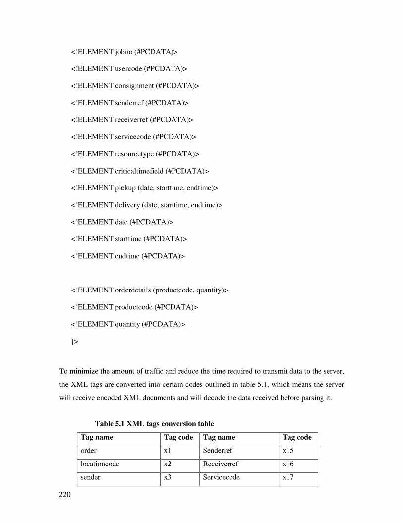
220
<!ELEMENT jobno (#PCDATA)>
<!ELEMENT usercode (#PCDATA)>
<!ELEMENT consignment (#PCDATA)>
<!ELEMENT senderref (#PCDATA)>
<!ELEMENT receiverref (#PCDATA)>
<!ELEMENT servicecode (#PCDATA)>
<!ELEMENT resourcetype (#PCDATA)>
<!ELEMENT criticaltimefield (#PCDATA)>
<!ELEMENT pickup (date, starttime, endtime)>
<!ELEMENT delivery (date, starttime, endtime)>
<!ELEMENT date (#PCDATA)>
<!ELEMENT starttime (#PCDATA)>
<!ELEMENT endtime (#PCDATA)>
<!ELEMENT orderdetails (productcode, quantity)>
<!ELEMENT productcode (#PCDATA)>
<!ELEMENT quantity (#PCDATA)>
]>
To minimize the amount of traffic and reduce the time required to transmit data to the server,
the XML tags are converted into certain codes outlined in table 5.1, which means the server
will receive encoded XML documents and will decode the data received before parsing it.
Table 5.1 XML tags conversion table
Tag name Tag code Tag name Tag code
order x1 Senderref x15
locationcode x2 Receiverref x16
sender x3 Servicecode x17
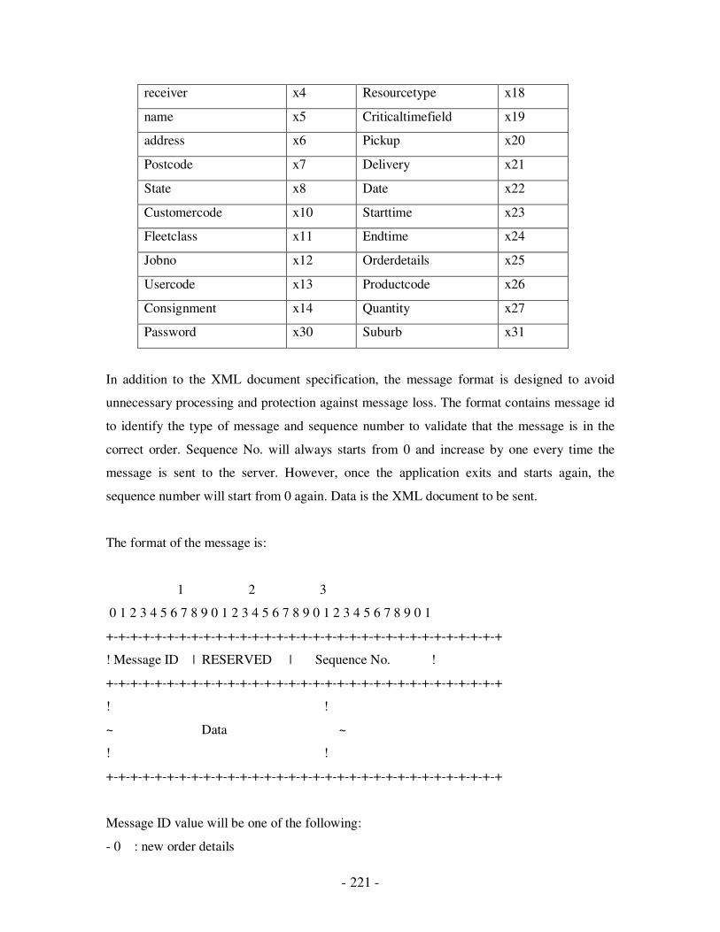
- 221 -
receiver x4 Resourcetype x18
name x5 Criticaltimefield x19
address x6 Pickup x20
Postcode x7 Delivery x21
State x8 Date x22
Customercode x10 Starttime x23
Fleetclass x11 Endtime x24
Jobno x12 Orderdetails x25
Usercode x13 Productcode x26
Consignment x14 Quantity x27
Password x30 Suburb x31
In addition to the XML document specification, the message format is designed to avoid
unnecessary processing and protection against message loss. The format contains message id
to identify the type of message and sequence number to validate that the message is in the
correct order. Sequence No. will always starts from 0 and increase by one every time the
message is sent to the server. However, once the application exits and starts again, the
sequence number will start from 0 again. Data is the XML document to be sent.
The format of the message is:
1 2 3
0 1 2 3 4 5 6 7 8 9 0 1 2 3 4 5 6 7 8 9 0 1 2 3 4 5 6 7 8 9 0 1
+-+-+-+-+-+-+-+-+-+-+-+-+-+-+-+-+-+-+-+-+-+-+-+-+-+-+-+-+-+-+-+-+
! Message ID | RESERVED | Sequence No. !
+-+-+-+-+-+-+-+-+-+-+-+-+-+-+-+-+-+-+-+-+-+-+-+-+-+-+-+-+-+-+-+-+
! !
~ Data ~
! !
+-+-+-+-+-+-+-+-+-+-+-+-+-+-+-+-+-+-+-+-+-+-+-+-+-+-+-+-+-+-+-+-+
Message ID value will be one of the following:
- 0 : new order details

222
- 1 : check invoice balance
- 2 : client registration conformation
- 3 : proof of delivery update
- 10 : synchronization
- 200 : reply
- 250 : Error message
5.2.6 Error handling protocol
Errors are very common in communications. They might be caused either by communication
failure or due to wrong input from users. But for the appropriate functioning of the system, it
should be free from errors. The errors that occur at the client side are easy to handle whereas
the errors occurred at server side need client to be notify about it. In order to accommodate
errors at the server side, an error protocol has been developed. The error message sent from
the server follows the same message format as the communication protocol. Messages from
the server that carry error codes will use message ID 250. The error code contained in the
message will be formatted using an XML tag with the following Document Type Definition:
<?xml version=”1.0”?>
<!DOCTYPE error [
<!ELEMENT error (#PCDATA)>
]>
Table 5.2 Server error code
Error Code Meaning
201 Invalid tag
202 Invalid data format
203 Invalid XML
220 Booking no is not found
222 Invalid customer code
223 Invalid date format
224 Invalid product code
401 Invalid message id
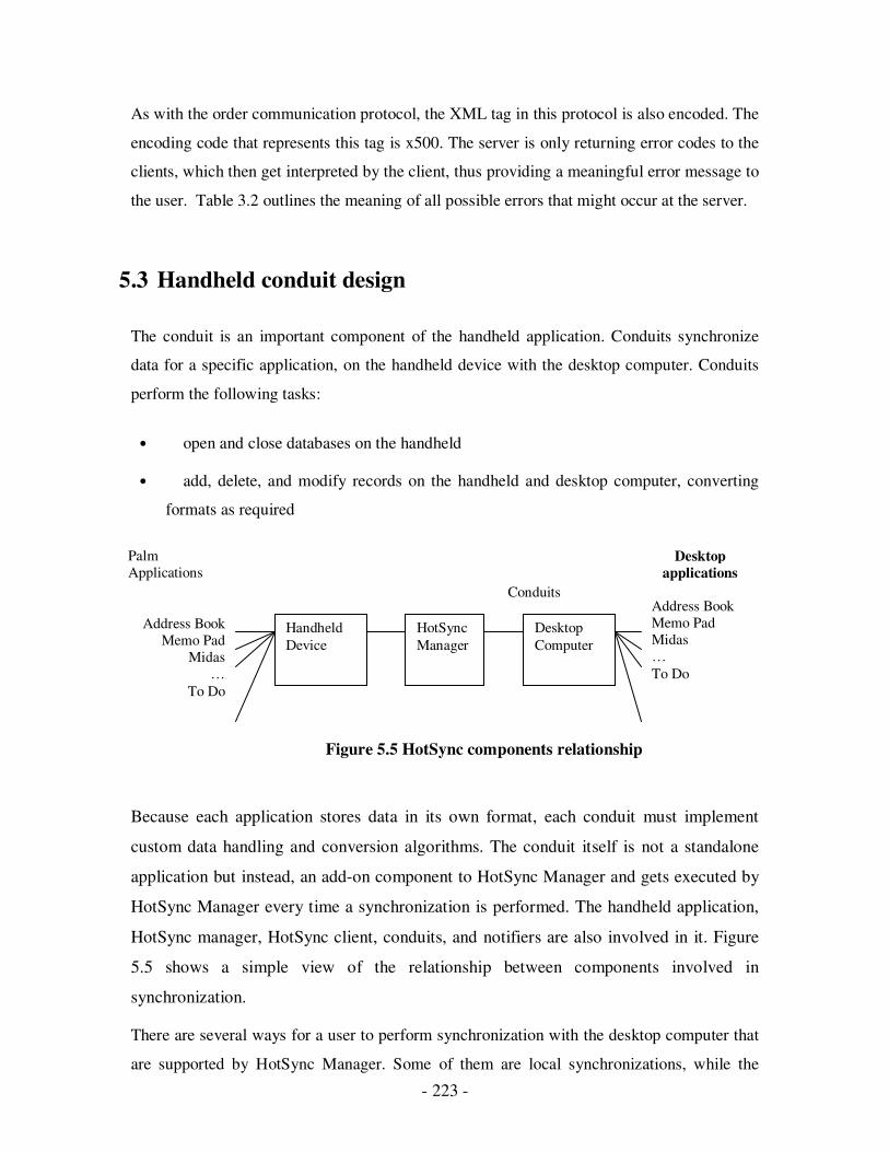
- 223 -
As with the order communication protocol, the XML tag in this protocol is also encoded. The
encoding code that represents this tag is x500. The server is only returning error codes to the
clients, which then get interpreted by the client, thus providing a meaningful error message to
the user. Table 3.2 outlines the meaning of all possible errors that might occur at the server.
5.3 Handheld conduit design
The conduit is an important component of the handheld application. Conduits synchronize
data for a specific application, on the handheld device with the desktop computer. Conduits
perform the following tasks:
• open and close databases on the handheld
• add, delete, and modify records on the handheld and desktop computer, converting
formats as required
Figure 5.5 HotSync components relationship
Because each application stores data in its own format, each conduit must implement
custom data handling and conversion algorithms. The conduit itself is not a standalone
application but instead, an add-on component to HotSync Manager and gets executed by
HotSync Manager every time a synchronization is performed. The handheld application,
HotSync manager, HotSync client, conduits, and notifiers are also involved in it. Figure
5.5 shows a simple view of the relationship between components involved in
synchronization.
There are several ways for a user to perform synchronization with the desktop computer that
are supported by HotSync Manager. Some of them are local synchronizations, while the
Handheld
Device
Desktop
Computer
HotSync
Manager
Conduits
Palm
Applications
Address Book
Memo Pad
Midas
…
To Do
Desktop
applications
Address Book
Memo Pad
Midas
…
To Do
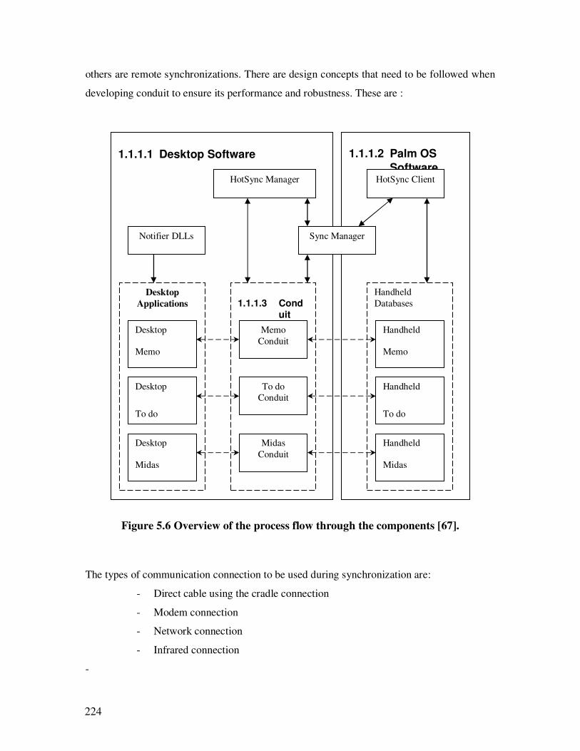
224
others are remote synchronizations. There are design concepts that need to be followed when
developing conduit to ensure its performance and robustness. These are :
Figure 5.6 Overview of the process flow through the components [67].
The types of communication connection to be used during synchronization are:
- Direct cable using the cradle connection
- Modem connection
- Network connection
- Infrared connection
-
1.1.1.1 Desktop Software 1.1.1.2 Palm OS
Software
Handheld
Databases 1.1.1.3 Conduit
Desktop
Applications
Desktop
Memo
Desktop
To do
Desktop
Midas
Memo
Conduit
To do
Conduit
Midas
Conduit
HotSync Manager
Notifier DLLs Sync Manager
HotSync Client
Handheld
Memo
Handheld
To do
Handheld
Midas

- 225 -
- Fast execution: The main goal for the HotSync process is a quick and successful
synchronization. This means that conduits need to be designed for optimal processing
speed and minimal data transfer between the desktop computer and handheld device.
Zero data loss: Conduits must take measures required to prevent data loss under any
circumstances, including loss of connection during a HotSync operation.
-
- Good conflict handling: Mirror image synchronization performed by conduits should be
handled very carefully and free from any conflicts. This is also known as “double
modify”. This is a conflict when the user modifies data at both the desktop computer and
handheld device.
- No user interaction: Users always expect minimum interaction during synchronization,
so conduits need to be developed in that way that is good practice. This is especially
important for users who are performing synchronization remotely.
Data synchronization by conduits, and data integrity, in case of modification situations,
should be performed correctly whenever the user wants to make changes. Status bits (see
figure 5.2) maintained for each record are used in determining which course of action
should be taken. Table 5.3 describes all possible scenarios and related actions that are
required during data synchronization
Table 5.3 Records synchronization logic
Handheld
Record Status
Desktop
Record Status
Action
Add No record Add the handheld record to the desktop
databases.
Archive Delete Archive the handheld record and delete the
record from both the handheld and desktop
databases.
Archive No change Archive the handheld record and delete the
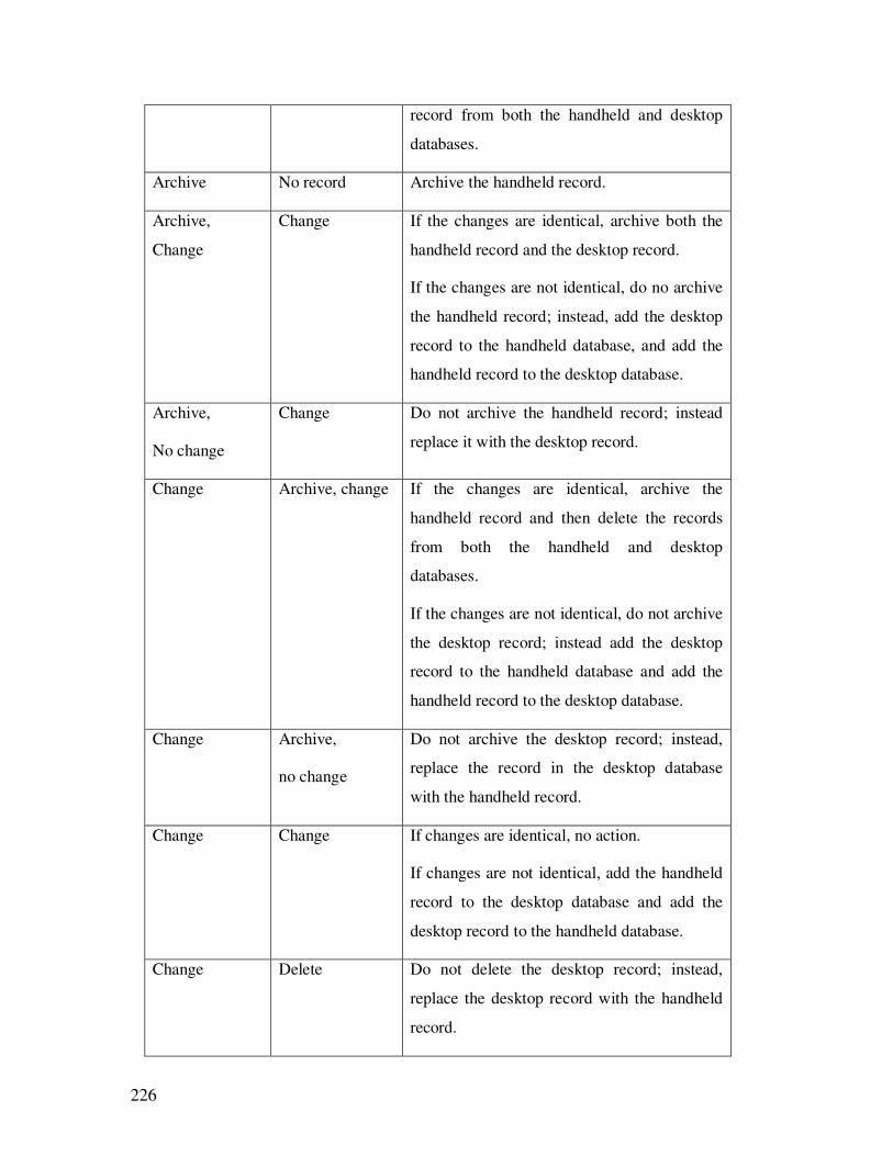
226
record from both the handheld and desktop
databases.
Archive No record Archive the handheld record.
Archive,
Change
Change If the changes are identical, archive both the
handheld record and the desktop record.
If the changes are not identical, do no archive
the handheld record; instead, add the desktop
record to the handheld database, and add the
handheld record to the desktop database.
Archive,
No change
Change Do not archive the handheld record; instead
replace it with the desktop record.
Change Archive, change If the changes are identical, archive the
handheld record and then delete the records
from both the handheld and desktop
databases.
If the changes are not identical, do not archive
the desktop record; instead add the desktop
record to the handheld database and add the
handheld record to the desktop database.
Change Archive,
no change
Do not archive the desktop record; instead,
replace the record in the desktop database
with the handheld record.
Change Change If changes are identical, no action.
If changes are not identical, add the handheld
record to the desktop database and add the
desktop record to the handheld database.
Change Delete Do not delete the desktop record; instead,
replace the desktop record with the handheld
record.
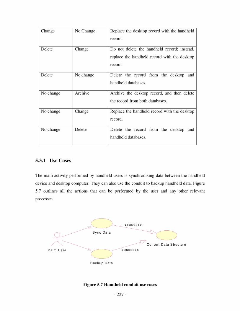
- 227 -
Change No Change Replace the desktop record with the handheld
record.
Delete Change Do not delete the handheld record; instead,
replace the handheld record with the desktop
record
Delete No change Delete the record from the desktop and
handheld databases.
No change Archive Archive the desktop record, and then delete
the record from both databases.
No change Change Replace the handheld record with the desktop
record.
No change Delete Delete the record from the desktop and
handheld databases.
5.3.1 Use Cases
The main activity performed by handheld users is synchronizing data between the handheld
device and desktop computer. They can also use the conduit to backup handheld data. Figure
5.7 outlines all the actions that can be performed by the user and any other relevant
processes.
Figure 5.7 Handheld conduit use cases
Convert Data S tructure
Sy nc Data
P alm Us er
B ac kup Data
<< us es> >
< <uses> >
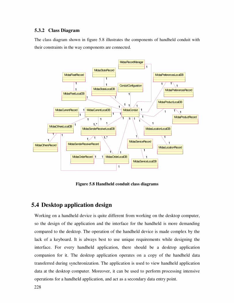
228
5.3.2 Class Diagram
The class diagram shown in figure 5.8 illustrates the components of handheld conduit with
their constraints in the way components are connected.
Figure 5.8 Handheld conduit class diagrams
5.4 Desktop application design
Working on a handheld device is quite different from working on the desktop computer,
so the design of the application and the interface for the handheld is more demanding
compared to the desktop. The operation of the handheld device is made complex by the
lack of a keyboard. It is always best to use unique requirements while designing the
interface. For every handheld application, there should be a desktop application
companion for it. The desktop application operates on a copy of the handheld data
transferred during synchronization. The application is used to view handheld application
data at the desktop computer. Moreover, it can be used to perform processing intensive
operations for a handheld application, and act as a secondary data entry point.
ConduitConfiguration
MidasRecordManager
MidasPreferencesLocalDB
MidasPreferencesRecord
11
MidasProductRecord
MidasLocationRecord
MidasServiceLocalDB
MidasFleetRecord
MidasStateRecord
MidasProductLocalDB
11
MidasLocationLocalDB
1
1
MidasServiceRecord
1
1
MidasFleetLocalDB
1
1 MidasStateLocalDB
1
1
MidasSenderReceiverRecord
MidasCurrentRecord
MidasOrderRecord
MidasCurrentLocalDB
1
1
MidasOrderLocalDB11
MidasOthersLocalDB1
1
1
1
MidasOthersRecord
1
1
1
1
1
1
MidasSenderReceiverLocalDB
1..*
1
1..*
1
1 1 1..*
1
MidasConduit
1
1
1
1
1
1
1
1
1
11
1
11
1
1
1
1
1
1
1
1
1
1
1 11 1
1
11
1
1
1
1
1
1
1
1
1
1
1
111..*
1
11
1
1
1
1
1
1
11
1
1
1
1 11
1
1 11
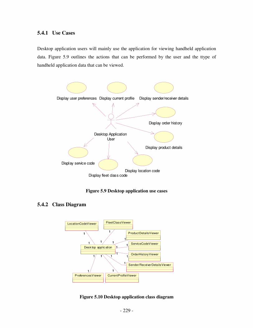
- 229 -
5.4.1 Use Cases
Desktop application users will mainly use the application for viewing handheld application
data. Figure 5.9 outlines the actions that can be performed by the user and the ttype of
handheld application data that can be viewed.
Figure 5.9 Desktop application use cases
5.4.2 Class Diagram
Figure 5.10 Desktop application class diagram
Display user preferences Display current profile Display sender/receiver details
Display order history
Display product details
Display location codeDisplay fleet class code
Desktop Application
User
Display service code
PreferencesViewer CurrentProfileViewer
Sender/ReceiverDeta ilsViewer
OrderHistoryViewer
ServiceCodeViewer
ProductDetailsViewer
FleetClassViewer
Desk top appl ic ation
1
1
1
1
1
1
1
1 11
11
11
1
1
LocationCodeViewer
1
11
1
1
1
11
11
111
1
1
1
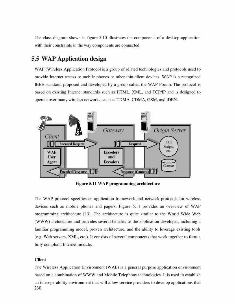
230
The class diagram shown in figure 5.10 illustrates the components of a desktop application
with their constraints in the way components are connected.
5.5 WAP Application design
WAP (Wireless Application Protocol is a group of related technologies and protocols used to
provide Internet access to mobile phones or other thin-client devices. WAP is a recognized
IEEE standard, proposed and developed by a group called the WAP Forum. The protocol is
based on existing Internet standards such as HTML, XML, and TCP/IP and is designed to
operate over many wireless networks, such as TDMA, CDMA, GSM, and iDEN.
Figure 5.11 WAP programming architecture
The WAP protocol specifies an application framework and network protocols for wireless
devices such as mobile phones and pagers. Figure 5.11 provides an overview of WAP
programming architecture [13]. The architecture is quite similar to the World Wide Web
(WWW) architecture and provides several benefits to the application developer, including a
familiar programming model, proven architecture, and the ability to leverage existing tools
(e.g. Web servers, XML, etc.). It consists of several components that work together to form a
fully compliant Internet module.
Client
The Wireless Application Environment (WAE) is a general purpose application environment
based on a combination of WWW and Mobile Telephony technologies. It is used to establish
an interoperability environment that will allow service providers to develop applications that
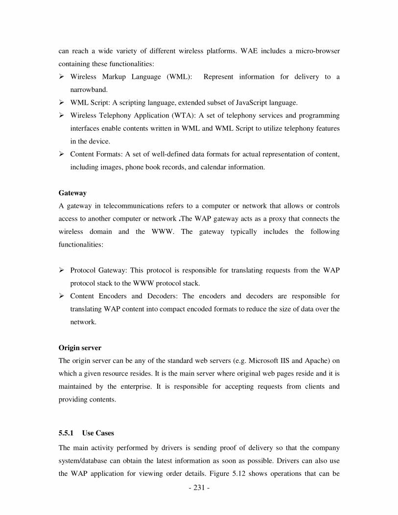
- 231 -
can reach a wide variety of different wireless platforms. WAE includes a micro-browser
containing these functionalities:
� Wireless Markup Language (WML): Represent information for delivery to a
narrowband.
� WML Script: A scripting language, extended subset of JavaScript language.
� Wireless Telephony Application (WTA): A set of telephony services and programming
interfaces enable contents written in WML and WML Script to utilize telephony features
in the device.
� Content Formats: A set of well-defined data formats for actual representation of content,
including images, phone book records, and calendar information.
Gateway
A gateway in telecommunications refers to a computer or network that allows or controls
access to another computer or network .The WAP gateway acts as a proxy that connects the
wireless domain and the WWW. The gateway typically includes the following
functionalities:
� Protocol Gateway: This protocol is responsible for translating requests from the WAP
protocol stack to the WWW protocol stack.
� Content Encoders and Decoders: The encoders and decoders are responsible for
translating WAP content into compact encoded formats to reduce the size of data over the
network.
Origin server
The origin server can be any of the standard web servers (e.g. Microsoft IIS and Apache) on
which a given resource resides. It is the main server where original web pages reside and it is
maintained by the enterprise. It is responsible for accepting requests from clients and
providing contents.
5.5.1 Use Cases
The main activity performed by drivers is sending proof of delivery so that the company
system/database can obtain the latest information as soon as possible. Drivers can also use
the WAP application for viewing order details. Figure 5.12 shows operations that can be
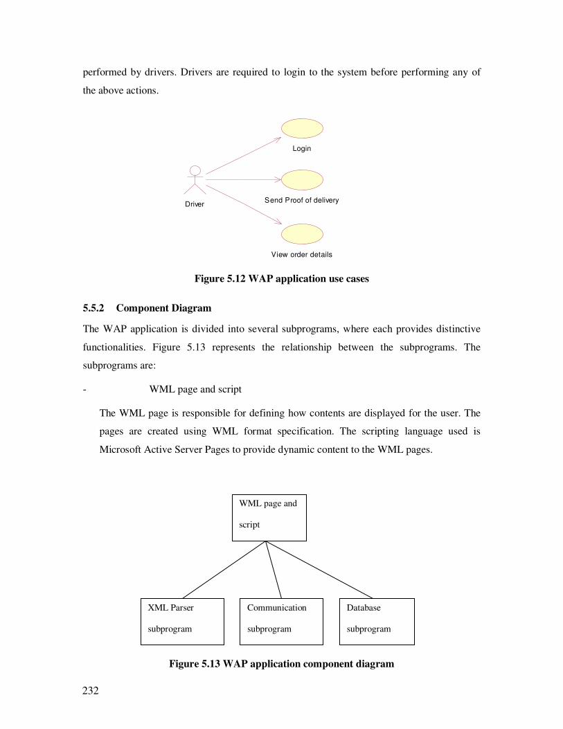
232
performed by drivers. Drivers are required to login to the system before performing any of
the above actions.
Figure 5.12 WAP application use cases
5.5.2 Component Diagram
The WAP application is divided into several subprograms, where each provides distinctive
functionalities. Figure 5.13 represents the relationship between the subprograms. The
subprograms are:
- WML page and script
The WML page is responsible for defining how contents are displayed for the user. The
pages are created using WML format specification. The scripting language used is
Microsoft Active Server Pages to provide dynamic content to the WML pages.
Figure 5.13 WAP application component diagram
Login
Send Proof of deliveryDriver
View order details
WML page and
script
Database
subprogram
Communication
subprogram
XML Parser
subprogram
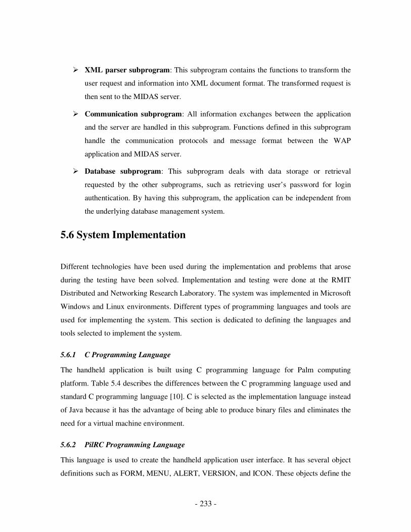
- 233 -
� XML parser subprogram: This subprogram contains the functions to transform the
user request and information into XML document format. The transformed request is
then sent to the MIDAS server.
� Communication subprogram: All information exchanges between the application
and the server are handled in this subprogram. Functions defined in this subprogram
handle the communication protocols and message format between the WAP
application and MIDAS server.
� Database subprogram: This subprogram deals with data storage or retrieval
requested by the other subprograms, such as retrieving user’s password for login
authentication. By having this subprogram, the application can be independent from
the underlying database management system.
5.6 System Implementation
Different technologies have been used during the implementation and problems that arose
during the testing have been solved. Implementation and testing were done at the RMIT
Distributed and Networking Research Laboratory. The system was implemented in Microsoft
Windows and Linux environments. Different types of programming languages and tools are
used for implementing the system. This section is dedicated to defining the languages and
tools selected to implement the system.
5.6.1 C Programming Language
The handheld application is built using C programming language for Palm computing
platform. Table 5.4 describes the differences between the C programming language used and
standard C programming language [10]. C is selected as the implementation language instead
of Java because it has the advantage of being able to produce binary files and eliminates the
need for a virtual machine environment.
5.6.2 PilRC Programming Language
This language is used to create the handheld application user interface. It has several object
definitions such as FORM, MENU, ALERT, VERSION, and ICON. These objects define the
234
actual user interface components and their properties such as id, location, and value. Refer to
page 217 for an example of PilRC codes for creating a user interface.
5.6.3 Java Programming Language
Desktop application and handheld conduit are built using the Java language with the help of
other development kits. Java language is selected as the language to implement the
components because it is platform independent, which enables the application to be executed
in either a Windows, or Mac platform.
Table 5.4 Difference between standard C and Palm OS C
Standard
C functions
Palm OS
functions
Additional Information
strlen StrLen
strcpy StrCopy
strncpy StrNCopy Does not pad with extra null terminators
strcat StrCat
strncat StrNCat Last parameter is the total length of the string
(including null terminator) rather then the number
of characters to copy. Does not pad a null
terminator if source string is empty
strcmp StrCompare
strncmp StrNCompare
itoa StrIToA
strchr StrChr
strstr StrStr
sprintf StrPrintF Limited subset of sprintf, for example, no %f
svprintf StrVPrintF Limited subset of svprintf, for example, no %f
malloc MemPtrNew The use of memory handle is preferred.
free MemPtrFree
memmove MemMove
memset MemSet The last two parameters have been reversed
memcmp MemCmp

- 235 -
5.6.4 VB Programming Language
The WAP application is developed using the VB programming language, which is part of the
Microsoft Visual Studio .Net. VB is selected because it provides ease of use and is the default
language for creating WAP applications in Visual Studio .Net.
5.6.5 PRC-Tools
This tool is used to compile Palm OS C codes into a resource file that can be executed by
Palm OS. This tool contains many utilities that are needed when developing handheld
applications. m68k-palmos-gcc is a compiler for Palm OS C codes. multigen (that reads
definition files) is a utility that generates an assembly language source file and a linker script,
for use in development with multiple code resources (segmented application source code).
The assembly stub file will need to be compiled with the application and the linker script
needs to be added to the link command. build-prc is a post-linker utility that reads resource
and definition files and produces one Palm OS .prc resource data file. By using all the
utilities defined, a handheld application (.prc) is created, which can be installed in the device.
5.6.6 PilRC compiler
This compiler reads in the codes created using the PilRC language and produces a series of
binary resource files that are used when developing Palm Powered™ handheld applications.
These resource files will then be combined with other codes to create the entire application.
5.6.7 Palm OS Software Development Kit
This SDK contains the headers, libraries, and tools for Palm OS platform development that is
necessary when creating handheld applications. It contains functions that help the developer
to create the application such as, network library functions, data and resource functions, and
user interface functions.
5.6.8 Conduit Development Kit
This CDK provides all required APIs for conduit development for Windows and/or Mac
platforms. APIs defined in this development kit contain functions to communicate with the
HotSync Manager and also generic record structure of handheld application data.

236
5.6.9 Microsoft Visual .Net with Mobile Internet Framework
This IDE is used to develop the WAP application component of the system. The development
of this application requires mobile Internet framework extension to be installed, which
contains the definitions of mobile applications.
5.7 Testing
The method of testing is a sort of Black-box testing, where the attention is on the desired
behaviour of the system and not on how the code works. No attention is paid to the
underlying language or program code.
All features of the system have been tested for integrity, including the handheld application,
handheld conduit, desktop application, WAP application, and integration with the rest of the
system and the environment. Access privileges were tested to ensure that only individuals
who are entitled to access particular information are allowed to do so without others being
able to access the same information. The system was tested to ensure that accessibility is
available during the industry operational time. Testing includes the usability of user
interfaces and the correctness of information provided to users. The speed of access to the
various system features was also tested from different access points. The resources used
during testing were a fully functional web portal and MIDAS server, handheld device,
desktop computer, and system modules discussed in this report.
5.7.1 Handheld application testing
Testing on this module is centred on its capability to send new orders, check invoices, history
maintenance, add sender/receiver details, and add product details. Input validation is also
checked during the test period.

- 237 -
Functionality testing:
Table 5.5 Test cases and their actual and final results.
Test case Purpose Expected result Actual result Pass
1. Submit a
new order to
the server
Core of the
business
The server returns a
order number on valid
data, else returns error
As Expected Yes
2. Find the
amount owing
on an order
So that the
customer knows
how much they
owe
On valid input --return
the amount owing on
a order, return error
on invalid input
As Expected Yes
3. Store user
profile on the
client
So that user does
not need to type
redundant
information again
Previous values
should be loaded by
default
As Expected Yes
4. History
maintenance
So that user has
records of orders
that has been sent
from handheld
Sent order should be
added to history list
and it can be retrieved
correctly
As Expected Yes
5. Add
sender/receiver
details
To help user in
filling the order
details.
New sender/receiver
should be added to the
list and can be
retrieved correctly
As Expected Yes
6. Add product
details
So that user can
add new product to
the list of possible
product to be sent
New product details
should be added to the
list and displayed
during product
selection
As Expected Yes

238
Validation testing:
Table 5.6 Results of validation testing
Attributes Test Expected result Actual result Pass
1. Pickup
Date
Accept date in
correct format.
No room for error
(calendar selection
form).
OK Yes
2. Delivery
Date
Accept date in
correct format.
No room for error
(calendar selection
form).
OK Yes
3. Pickup
Start Time
Accept date in
correct format.
No room for error
(time selection
form).
OK Yes
4. Pickup
End Time
Accept date in
correct format.
No room for error
(time selection form)
OK Yes
5. Delivery
Start Time
Accept date in
correct format.
No room for error
(time selection form)
OK Yes
6. Delivery
End Time
Accept date in
correct format.
No room for error
(time selection form)
OK Yes
7. Product
Code
Accept only the
listed product code
No room for error
(drop down list)
OK Yes
8. Sender
Name
Should not be
empty or contain
only white spaces
User enters sender
name
OK Yes

- 239 -
9. Sender
Address
Should not be
empty or contain
only white spaces
User enters sender
address
OK Yes
10. Sender
Suburb
Should not be
empty or contain
only white spaces
User enters sender
suburb
OK Yes
11. Sender
State
Should not be
empty or contain
only white spaces
User enters sender
state
OK Yes
12. Sender
Post Code
Should not be
empty or contain
only white spaces
User enters sender
postcode
OK Yes
13. Sender
Reference
Should not be
empty or contain
only white spaces
User enters sender
reference
OK Yes
14. Receiver
Name
Should not be
empty or contain
only white spaces
User enters receiver
name
OK Yes
15. Receiver
Address
Should not be
empty or contain
only white spaces
User enters receiver
address
OK Yes
16. Receiver
Suburb
Should not be
empty or contain
only white spaces
User enters receiver
suburb
OK Yes
17. Receiver
State
Should not be
empty or contain
only white
User enters receiver
state
OK Yes

240
spaces
18. Receiver
Post Code
Should not be
empty or contain
only white
spaces
User enters receiver
postcode
OK Yes
19. Receiver
Reference
Should not be
empty or contain
only white spaces
User enters receiver
reference
OK Yes
20. Location
Code
Should not be
empty or contain
only white spaces
User enters location
code
OK Yes
21.
Customer
Code
Should not be
empty or contain
only white spaces
User enters customer
code
OK Yes
22. User
Code
Should not be
empty or contain
only white spaces
User enters user
code
OK Yes
23. Fleet
Class
Should not be
empty or contain
only white spaces
User enters fleet
class
OK Yes
24. Service
Code
Should not be
empty or contain
only white spaces
User enters service
code
OK Yes
25. Should not be User enters OK Yes
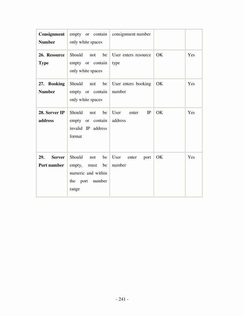
- 241 -
Consignment
Number
empty or contain
only white spaces
consignment number
26. Resource
Type
Should not be
empty or contain
only white spaces
User enters resource
type
OK Yes
27. Booking
Number
Should not be
empty or contain
only white spaces
User enters booking
number
OK Yes
28. Server IP
address
Should not be
empty or contain
invalid IP address
format
User enter IP
address
OK Yes
29. Server
Port number
Should not be
empty, must be
numeric and within
the port number
range
User enter port
number
OK Yes

242
5.7.2 Handheld conduit testing
Testing on this module is centred on its capability to synchronize handheld data with desktop
data.
Functionality Testing:
Table 5.7 results for functionality testing
Test case Purpose Expected result Actual result Pass
1. Synchronization
for the first time
Synchronize
data between
handheld and
desktop
All handheld data
get copy to
desktop
As Expected Yes
2. Synchronization
with the same
desktop
To test if fast
synchronization
works correctly
Modified records
get synchronized
As Expected Yes
3. Synchronization
with different
desktop
To test if slow
synchronization
works correctly
Modified records
get synchronized
As Expected Yes
4. Checking the data
storage
To check if data
is in the correct
state after
synchronization
Data is in correct
state
As Expected Yes

- 243 -
5.7.3 Desktop application testing
Testing on this module is centred on its capability to display handheld data at the desktop
computer.
Functionality Testing:
Table 5.8 Functionality testing results for Desktop application testing
Test case Purpose Expected result Actual result Pass
1. Display user
preferences
Displaying user
preferences
information from
handheld
Display correct
information
As Expected Yes
2. Display
current profile
Displaying user
current profile
information from
handheld
Display correct
information
As Expected Yes
3. Display
sender/receiver
details
Displaying list of
sender/receiver
information from
handheld
Display correct
information
As Expected Yes
4. Display order
history
Displaying list of
order history
information from
handheld
Display correct
information
As Expected Yes
5. Display
product details
Displaying list of
product
information from
handheld
Display correct
information
As Expected Yes
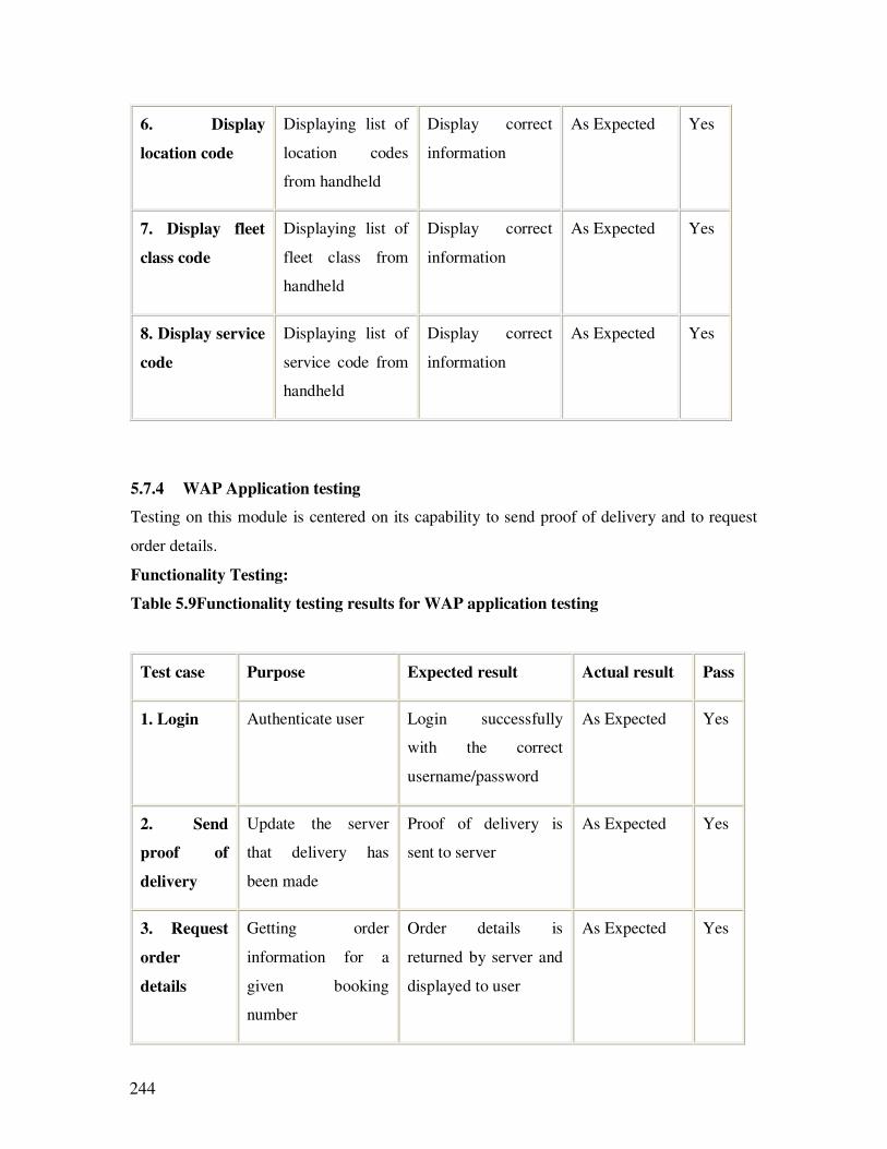
244
6. Display
location code
Displaying list of
location codes
from handheld
Display correct
information
As Expected Yes
7. Display fleet
class code
Displaying list of
fleet class from
handheld
Display correct
information
As Expected Yes
8. Display service
code
Displaying list of
service code from
handheld
Display correct
information
As Expected Yes
5.7.4 WAP Application testing
Testing on this module is centered on its capability to send proof of delivery and to request
order details.
Functionality Testing:
Table 5.9Functionality testing results for WAP application testing
Test case Purpose Expected result Actual result Pass
1. Login Authenticate user Login successfully
with the correct
username/password
As Expected Yes
2. Send
proof of
delivery
Update the server
that delivery has
been made
Proof of delivery is
sent to server
As Expected Yes
3. Request
order
details
Getting order
information for a
given booking
number
Order details is
returned by server and
displayed to user
As Expected Yes

- 245 -
It should be noted that it is difficult to migrate developments to other platforms due to the
system’s architecture dependency. Changes to the code can be done, such as using a
platform-specific separator character when constructing path names. Further, different
problems occur for various dependent bugs. In other words, the errors occurring for a
version-dependent software is different to an operating system.

- 246 -
Chapter 6
Conclusion and Future work
6.1 Conclusion
6.1.1 Dynamic communication Protocol:
For communication between agents, three major considerations are
• a reliable communication system
• a common understanding of the data being exchanged
• an understanding of the sequence of exchanges, forming a valid communication
protocol
In the context of the Internet, agents may be diverse in nature. Therefore, it is not
possible to have prior knowledge of all possible protocols that may be needed for
communication. In this project, I proposed a communication protocol that could be
implemented to operate between agents and services. The language used for the
implementation is XML. This avoids implementing any predefined object formats
being passed between agents, or any internal representation of data formats being
exchanged. This protocol specification is parsed into a state machine and state
machine used messages representing fundamental concepts for the domain. A third
factor that should be taken into consideration is primitive vocabulary phrases, or
messages that can be used to make communication protocols. A common
understanding of phrases promotes interoperability.
[28] presented a framework for trading scenarios, which was based on an extension
of a Java-based version of the Fishmarket trade. The investigation explains the
- 247 -
various operations involved in the auction house, and defines a protocol for the
bidding process. Our investigation, on the other hand, involved a wine merchant.
Further, the interaction between buyers and the market was also modeled on a
communication protocol. A finite state machine was used to model the coordination
and structured conversations in this systems. In our case, a complex communicating
state machine was employed.
Both [26] and [27] proposed an inter-agent (autonomous software agent), JIM, that
promoted communication and coordination among agents composing a multi-agent
system. Our investigation involved a dynamic communication protocol. They also
devised a conversation protocol to handle the coordination aspect. Where [26] used
a hierarchical interaction protocol, SHIP, to support agent interaction, [27]
employed the agent communication language, KQML (Java was used once again due
to its platform independence). Similar to [28], both [26] and [27] also implemented
their protocol in a Fishmarket scenario.
In our investigation of multi-agent systems, a Java-based inter-agent was devised,
which handled both the communication and coordination aspects. The major
difference was that this was part of a bigger picture – the next section dealt with
protocol correctness.
It is important to note that the dynamic implementation of protocols refers to agents
having the ability to communicate with each other through a protocol which can
learn their language, or already has an understanding of that language. Protocol
specifications simply define the rules of the communication; they do not enter the
domain the languages and do not play a part in the ‘understanding’ of
communication between agents. The dynamic interpretation of protocol
specifications is not the intention of this investigation. This study deals with a
protocol having the ability to adapt to changes in messages between agents.
In the testing of a wine merchant’s implementation, we have created three different
protocols, and the requirements for interoperation with clients were published, as a
state machine specification using XML. A client agent can dynamically construct

- 248 -
and communicate with all merchant agents. This can be possible due to common
vocabulary and understanding.
This policy has different advantages as follows:
• Implementation does not require knowledge of conversation details at
compile time, so that interfaces and expected messages do not become a
legacy.
• With common vocabulary knowledge, any number of protocols can be
created at the time of communication with a variety of agents.
• Agents wishing to use services are not restricted to any specific execution
framework.
• E services can change their conversation details at any time without affecting
clients.
There is one limitation also. If a client does not have the knowledge of fundamental
vocabulary, it is not possible to construct, validate and traverse the state machine
required for agent interoperation. However, this is possible for domain specific
clients. In this implementation, client agents are able to interact with any merchant
who understands the terms “Buy”, “Bid” and “Sale” etc. This limitation is a
significant one. A software agent created to perform a specific task may not be able
to interact in a different domain.
In this implementation, all the specified protocols have product brokering to match
the type of product before interaction. It is similar to providing the username and
password to match a user’s identification. Here some similarity matching algorithms
are used to check for similar agents to offer the services to the matched one. In our
example, the wine implementation used feature vectors and a similarity algorithm to
provide the similarity matching of wine products.
In the context of the project I have identified some of the issues involved in aiming
towards agents to agent operability in the open environment such as the Internet.
- 249 -
6.1.2 Protocol Correctness
Software applications interact with each other to exchange information and services.
Agents exchange information using a valid sequence that forms a communication
protocol. The behavior of these agents can be modeled using Communicating Finite
State Machine (CFSMs). But CFSMs do not have much expressive power to provide a
hierarchical view of a complex protocol, thus reflecting its varying level of granularity.
To overcome this limitation, CCSMs are used, which provide support for nested states.
CCSMs support hierarchy, modularity, component reuse and concise presentation of
large and complex protocols. A communication protocol should be validated against the
existence of logical errors, to provide the quality assurance of a communication system.
We have used state and partial exploration techniques for this purpose. We also
compare a few of these validation techniques, the results of which are summarized
below:
� In the deadlock detection algorithm, the number of possible deadlock states will
be much less than the number of total states in the communication system.
� In the deadlock detection procedure, if the number of possible deadlock states
are n and m, for a two-process system, the time complexity of our algorithm will
be O([m*b]n), where b is the complexity of the Backtrack procedure.
� The best case for Backtrack will be when the expected message is found in the
first instance. The Backtrack complexity will then be 1 and the best case
deadlock detection complexity will be O(mn).
� The worst case for Backtrack will be generation of all the states in the state
machine. In this case, deadlock detection complexity can also be represented as
O([m*s]n), where s is the number of states in the state machine, with m deadlock
states. This means that the complexity of the Backtrack procedure is equal to the
number of states in the state machine, which is highly unlikely. This is because
- 250 -
it indicates that all possible states are deadlock states, which means there would
be no message transfer between states, resulting in no communication.
Therefore, regardless of whether the state receives or send messages, it will
always be in a deadlock state.
We tested the operation of proposed validation techniques on various protocols, and
compared the results using reachability analysis and reverse reachability analysis. We
discovered that our technique is able to detect both the presence and the absence of
deadlock errors in the protocols. The algorithm can perform better than reachability
analysis, and almost equally well in many cases. Further, it provides an additional
option - to divide the analysis of possible deadlock states into two independent
subtasks, which can be executed in parallel to reduce the time complexity of the
analysis.
6.1.3 Routing and scheduling
MIDAS provides a complete intelligent solution for truck companies in Australia. It
ensures all their customers a complete, satisfying and intelligent system because of
its portable, secure, flexible, mobile and scalable nature. It not only monitors the
truck movements, it also allows customers to dynamically route and schedule the
driver’s movements depending on the current order. With the power of MIDAS, it is
possible to give orders anywhere at any time, even the checking of account
balances. This software has improved the Australian transport industry as a whole,
through electronic commerce by exchanging information with customers, especially:
� Proof of Delivery documents
� Freight tracking
� Communication with vehicles
� Purchasing and supply
� Meeting regulatory requirements of government, information provision such
as weather reports and traffic congestion.
MIDAS improves customer service, maximizes profitability, increase revenue and
market share by positioning the supply chain to meet forecast demand, intelligently

- 251 -
promising and capturing orders, seamlessly executing and delivering order and
monitoring the entire fulfillment cycle.
6.1.4 Wireless
The implementation of MIDAS has proved to be a positive approach with good
results. Most requirements are fulfilled using these system components. A major
requirement is to exchange information using handheld devices using the wireless
network. A system has been developed, with various factors such as performance,
robustness, scalability and usability. Since MIDAS is a three-tier structure, it is a
scalable system and can handle extensions, if required in the future. The first
version has been released and demonstrated to transport companies and research
center representatives. This version is capable of performing information exchange,
user profiling and error handling using a wireless network. Enhancements on the
first version have been completed after feedback. Now, the system is capable of
performing data synchronization between handheld devices and desktop computers.
But due to these enhancements, the system is much more complex.
Some problems were faced during the implementation of the system:
• Difficulty in managing the table component of the user interface, where the
developer needs to control all aspects of the table, including table scrolling.
• Palm devices do not have a large amount of memory i.e. only 32Kb of
memory. Hence, the entire application cannot be stored at one time and needs
to be compiled into steps.
• Sometimes, due to lack of memory stack, overflow occurs during
implementation and testing.
• Limited number of programming language functions available, such as a
string tokenizer, thus requiring manual tokenizing.
• As the format is not same, there is a need to convert the data format of the
handheld application to a desktop application.
- 252 -
The system has been tested and presented on real devices (Palm m515 running
Palm OS 4.1), with a GSM network connection, and it takes less than 30 seconds
for information to be processed and sent, and replies from the server to be
received. In conclusion, this system is a great achievement in the transport
industry. It does not require a lot of alterations in the current system; it will be a
new enhancement with ease of work, and good productivity. This system has the
ability to do electronic business transactions and service customers.
Conclusion:
The MIDAS server acts as a milestone of the MIDAS project and provides an
autonomous delivery management system. Its functionalities range from taking
client orders to proof of deliveries for the transport industry. Using MIDAS has
increased the effectiveness and efficiency, and has decreased delivery time.
Technology provides various comprehensive solutions like digital maps and SMS to
overcome missing components of the traditional approach. Implementation of route
scheduling, along with the closest point nomination, path searching and insertion
schedule are implemented. MIDAS provides support for mobile device users,
Internet users, vehicle drivers and system operators by interacting with the
autonomous system through network connectivity. We are using digital maps for
Australia, which covers all major roads and suburbs of Victoria. Using these maps,
system operators can track drivers, vehicles and routes.
The MIDAS server communicates in two ways – TCP/IP technology is used for
application communication, whereas SMS is required for drivers to stay in touch.
Route scheduling relies on two searches. The first one is a local search, which
provides the shortest path information between individual points, and the second
one is a global search, which is mainly to schedule time arrangement between
multiple locations. Firstly, a local search is performed using digital maps, and an
insertion algorithm is applied for a global search. This project completely
implements route scheduling using digital map data and the insertion algorithm.
- 253 -
6.2 Future Work
6.2.1 Dynamic communication protocol
In the entire project, we are considering the Internet as the medium, where there
are a variety of agents communicating with each other for services.
Communication is possible only when there is a common understanding of
messages, and both agents can understand messages sent by each other. In this
project we are considering traditional client/server agents. Relationship among
agents could be either peer-to-peer or Client/server.
In a peer-to-peer society, it is difficult to determine which agent would
dynamically implement which protocol. In a collaborative approach, an agent
might publish its own protocol specification, which other agents are able to
implement. This would quickly lead to a complex network of different
communication protocols. TCP sockets and Java Servlets were used to provide
implementation. In an environment of enterprise level e-services, distributed
object architecture between distributed services may be reasonably expected.
Implementation of dynamic conversation protocols, tunneled in an application
layer distributed object protocol such as SOAP [12] may be required to represent
the expected interaction between client and server objects.
In a multi-agent environment, discovery of agents, and services provided by
other agents must be performed. While working in the agent framework, a
repository of agent services is available. Matching of requests and services can
be performed using product brokering and facilitator [25, 42]. Alternatively, a
client may contract the services [43] for tendering that it is seeking. But agents
operating outside the framework such as the Internet, do not have a well defined
method of service discovery. Discovery of agent services requires a yellow
pages look up for services, but on the Internet there is no such repository, so a
search engine can be used as centralized repository system.
- 254 -
Search engines have large databases, which can be viewed as a directory, and
used to list resources according to the keyword entered by the client.
6.2.2 Routing and Scheduling
Currently, digital maps contain information regarding major roads and suburbs,
but with the extension of details provided by the map, the feasibility of MIDAS
server scheduling can be enhanced. This is necessary for courier services. State
or suburb level maps are not sufficient, so street level maps are required. The
performance of the route scheduling is critical in terms of computation time and
a better solution. These factors have mainly affected the performance of the
MIDAS server in case of emergency orders, in which cases, street maps are a
necessity.
Caching is a useful mechanism in reducing the computation delay due to
dynamic routing in real time. In every execution, the route between two points
will be computed, even if they are at the same point. Along with the algorithm
improvement, caching techniques [44] [45] [46] should also be considered.
Hence, the application can cache a redundancy segment of routes, to prevent a
re-computation delay. During path searching, it sits on the top and requires
multiple comparisons of each route at different times, thus producing optimal
results. Moreover, caching can also reduce the rendering time.
While working in a wireless medium which is unguided, security is the prime
concern, so future versions of MIDAS must provide security mechanisms to
shield the application communication in open areas, such as encryption for data,
and digital signature for data integrity and authentication.
- 255 -
6.2.3 Wireless
This project is an enhancement for the transport industry. Different features of
the system provide the enhanced capability to perform the function effectively
and efficiently. Some features are yet to be developed, like security, desktop
application extension, the electronic signature, and the SOAP protocol.
Security: In a multi-agent environment, it is hard to implement security.
Platforms that are currently in use do not support much security, but it must be
mentioned that in future versions of handheld devices, there would be such
features. This means that industry standard data security protection can be added
to the software system.
Desktop Application Extension: The current implementation of the desktop
application that accompanies the handheld application can be extended to
include several other features such as support for input/output devices, acting as
an alternative application for which information can be sent to the server, and
performing data synchronization with the server, which acts as the data entry
point for handheld applications.
Electronic Signature: Handheld devices like Palm Powered have the capability
to capture graffiti from the screen where users enter information directly. This
feature can be used to improve the authenticity feature of the device, and to
make information sent to the server, more secure.
SOAP protocol: SOAP is a lightweight protocol and can be used as an
improvement to the current communication protocols in use. SOAP is based on
the XML document format, which makes it easy to add it to the current protocol.
SOAP uses the same language format and is a better way to improve the
system’s interoperability and extensibility.
- 256 -
Chapter 7
References [1] Deepika Chauhan JAFMAS - A Java-Based Framework for Multi-Agent Systems Development and Implementation. PhD Thesis, ECEDS Department, University of Cincinnati, 1997 [2] The Architecture of Aglets www.javaworld.com/javaworld/jw-04-1997/jw-04-hood.html [3] IBM Aglets Home page www.trl.ibm.co.jp/aglets
[4] http://www.objectspace.com/products/voyager/ ObjectSpace Voyager [5] http://www.concordiaagents.com/documents.html Mitsubishi Electra ITA – Concordia Java Mobile Agent Technology [6] http://www-poleia.lip6.fr/~merlat/JNA.html JavaNetAgents – A Java Platform for mobile agents execution on the Internet [7] Mihai Barbuceanu and Mark S. Fox COOL: A Language for Describing Coordination in Multi-Agent Systems Proceedings of the first International Conference on Multi-Agent Systems 1995 (ICMAS-95) [8] XCBL Index, available at http://www.xcbl.org [9] Arindam Banerji, Claudio Bartolini, Dorothea Beringer, Venkatesh Chopella, Kannan Govindarajan, Alan Karp, Harumi Kuno, Mike Lemon, Gregory Pogossiants, Shamik Sharma and Scott Williams. Web Services Conversation Language (WSCL) 1.0 March 2001. HP Laboratories, http://ww.e-speak.hp.com/media/wscl/_5_16_01.pdf [10] Harumi Kuno, Mike Lemon, Alan Karp and Dorothea Beringer. Conversation and Interfaces equals Business Logic. HP Labs Technical Reports HPL-2001-127 http://www.hpl.hp.com/techreports/2001/HPL-2001-127.html [11] Prof. Dr. Frank Leymann, Distinguished Engineer, IBM Software Group. Web Services Flow Language (WSFL 1.0) May 2001. http://www-4.ibm.com/software/solutions/webservices/pdf/WSFL.pdf

- 257 -
[12] Aaron Skonnard arSOAP: The Simple Object Access Protocol Microsoft Corporation, available a http://www.microsoft.com/mind/0100/soap/soap.asp [13] Tom Arnold, Jason Eaton SCMP (Simple Commerce Messaging Protocol) IETF Draft (work in progress) March 2001 [14] Example of a price comparison website (comparable to auctioning), available at www.mysimon.com [15] Ontology related links, available at www.ontology.org [16] Howard Smith and Kevin Poulter The Role of Shared Ontology in XML-Based Trading Architectures White Paper, Ontology.org available at http://www.ontology.org/main/papers/cacm-agents99.html [17] S.C. Cheung and J. Kramer Compositional Reachability Analysis of Finite-State Distributed Systems with User-Specified Constraints Proceedings of Third ACM Symposium on the Foundations of Software Engineering pp 140-151, 1995 [18] Danny B. Lange and Mitsuru Oshima Seven Good Reasons for Mobile Agents Communications of the A.C.M. March 1999 pp 88-89
[19]F.J. Lin, P.M. Chu and M.T. Liu Protocol Verification Using Reachability Analysis: The State Space Explosion Problem and Relief Strategies Computer Communication Review 17(5) pp 126-135, 1987 [20] Mark S Merkow, Jim Breitharpt and Ken L Wheeler Building SET applications for Secure Transactions, John Wiley & Sons, 1998 [21] Sunil Arya and David M. Mount Algorithms for Fast Vector Quantization Department of Computer Science, University of Maryland, 1993 [22] David A. White and Remesh Jain Similarity Indexing with the SS-tree Visual Computing Laboratory, University of California, San Diego, 1996
[23] Pattie Maes, Robert H. Guttman and Alexandros G. Moukas Agents That Buy and Sell Communications of the A.C.M. March 1999 pp 81-91
[24] Erich Gamma, Richard Helm, Ralph Johnson and John Vlissides
- 258 -
Design Patterns. Elements of Reusable Object-Oriented Software. Addison-Wesly 1st Edition 1995 [25] Tim Finin, Rich Fritzson, Don McKay and Robin McEntire KQML as an Agent Communication Language University of Maryland, Baltimore MD USA & Unisys Corporation Paoli PA USA, 1994 [26] Francisco J. Martin, Enric Plaza and Juan A. Rodriguez-Aguilar An Infrastructure for Agent-Based Systems: an Interagent Approach, International Journal of Intelligent Systems, Vol.15, pp 217-240 (2000) [27] Francisco J. Martin, Enric Plaza, Juan A. Rodriguez-Aguilar and Jordi Sabater JIM - A Java Interagent for Multi-Agent Systems, Proceedings of the AAAI Workshop on Software Tools for Developing Agents (1996). Also available at: http://reference.kfupm.edu.sa/content/j/i/jim_a_java_interagent_for_multi_agent_sy_930705.pdf [28] Juan A. Rodriguez-Aguilar, Fransisco J. Martin, Pablo Noriega, Pere Garcia and Carles Sierra Competitive Scenarios for Heterogeneous Trading Agents, Proceedings of the second international conference on Autonomous Agents, pp 293-300, May 1998 [29] The ARPA Knowledge Sharing Effort, available at : http://www.cs.umbc.edu/kqml/papers/desiderata-acl/section3.4.html [30] Solomon, M. “Algorithms for The Vehicle Routing and Scheduling Problems with Time Window Constrains”, Operations Research, Vol.35, No.2, 1987.
[31] Berger, J., Salois, M. and Begin, R. “A hybrid genetic algorithm for the vehicle routing problem with time windows”, In Proceedings of the 12th Bienneal Conference of the Canadian Society for Computational Studies of Intelligence, pages 114—127, 1998.
[32] Telstra Mobile SMS ACCESS MANAGER Technical Guide. http://www.telstra.com.au/mobilenet/pdf/sms_techguide.pdf
[33] BlueSkyFrog wireless service provider. http://business.blueskyfrog.com
[34] Larsen, J. “Vehicle Routing with Time Windows – Finding optimal solution efficiently”, DORSnyt, Sept 15, 1999.
[35] Geoscience Australia http://www.ga.gov.au
[36] Environment System Research Institute, Inc. “ESRI Shapefile Technical Description”, An ESRI White Paper, July 1998.
- 259 -
[37] Solomon, M. and Desrosiers J.“Time Windows Constrained Routing and Scheduling Problems”, Transportation Science, Vol.22, No.1, 1988.
[38] Savelsbergh, M. “Local Search in Routing Problem With Time Windows”, Annual Operations Research 4, 285-305, 1985.
[39] Michael R. Genesereth and Steven P. Ketchpel Software Agents - Communications of the ACM July 1994 pp 48-53 [40] Trip S. Chowdhry, Kevin Hughes (CommerceNet) eCo System: CommerceNet's Architectural Framework for Internet Commerce CommerceNet Inc, White Paper & Prospectus 1997, available at www.commerce.net [41] Gasser L. Social Conception of Knowledge and Action: DAI Foundation and Open Systems Artificial Intelligence vol 47, pp 107-138 [42] The Fishmarket Project. http://www.iiia.csic.es/Projects/fishmarket [43] Kwang Mong Sim and Raymond Chan A Brokering Protocol for Agent Based E-Commerce IEEE Transactions on Systems, Man and Cybernetics - pp 474-484 December 2000 [44] Castro, M., Adya, A., Liskov B., and Myers, A.C. “HAC: Hybrid Adaptive Caching for Distributed Storage Systems”, Proceedings of the 16th ACM Symposium on Operating Systems Principles, Saint-Malo, France, 5-8 Oct. 1997.
[45] O'Neil, E. J., O'Neil, P. E., and Weikum, G. “The LRU-K page replacement algorithm for database disk buffering”, In ACM SIGMOD Int. Conf. on Management of Data, pages 297-306, Washington, D.C., May 1993.
[46] Robinson, J., and Devarakonda, N. “Data cache management using frequency-based replacement”, In Proceedings of ACM SIGMETRICS Conference on Measurement and Modeling of Computer Systems, pages 134-142, 1990 [47] Forman G.H., and Zahorjan J., The Challenges of Mobile Computing, University of Washington, USA, 1994. [48] Gossett, B., Introduction to Conduit Development, http://www.palmos.com/dev/support/docs/, 2002. [49] Rohdes, N., and McKeehan, J., Ten Common Palm OS Programming Pitfalls, http://palmos.oreilly.com/news/palmosprog_1001.html, 2001. [50] American Freightways, http://www.palm.com/enterprise/studies/study33.html
- 260 -
[51] WAP - Architecture Specification, Version 30-Apr-1998. [52] Alexander Artikis, Jeremy Pitt and Christos Stergiou Agent Communication Transfer Protocol Proceedings of the fourth international conference on Autonomous agents, pp 491-498, 2000 [53] Moses Ma Agents in E-commerce Communications of the A.C.M. March 1999 pp 78-80 [54] Abid, C., A., Zouari, B., A distributed verification approach for modular Petri nets, Proceedings of the 2007 summer computer simulation conference, pp 681-690 (2007) [55] BBN Technologies http://openmap.bbn.com
[56] Environment System Research Institute, Inc. http://www.esri.com
[57] Hoch, F. “Assessing a wireless future”, Trends Report 2001, Oct 1, 2001.
[58] Imielinski T., and Badrinath B.R., Mobile Wireless Computing: Challenges in Data Management, Rutgers University, New Brunswick, NJ, 1994.
[59] Mykland, R., Palm OS Programming from the ground up, Osborne/McGraw- Hill, USA, 2000. [60] Winton, G., Palm OS Network Programming, 1st edition, USA, O’Reilly, 2001. [61] Foster, L. R., Palm OS Programming Bible, 1st edition, USA, IDG Books Worldwide Inc., 2000. [62] Wilson, G., and Ostrem J., Palm OS Programmer’s Companion, http://www.palmos.com/dev/support/docs/, 2002. [63] RSA Security, http://www.rsasecurity.com [64] WAP forum, http://www1.wapforum.org/member/developers/index.htm [65] Simple Object Access Protocol (SOAP) 1.1, http://www.w3.org/TR/SOAP/, 2000 [66] WAP - Wireless Telephony Application Specification, Version 30-Apr-1998.

- 261 -
[67] Gossett, B. (2002) Introduction to Conduit Development, available at http://www.accessdevnet.com/docs/conduits/win/Intro_CondPPPlatform.html#996015 [68] Martin, Robert C. (2008), Engineering Notebook Column, C++ Report, available at http://www.objectmentor.com/resources/articles/umlfsm.pdf [69] Hildebrandt, T. (2004), Labelled transition systems, CCS and the Mobility Workbench, Model-based Design of Distributed and Mobile Systems, available at http://www.itu.dk/courses/IMDD/F2005/Week1/slides1.pdf [70] FIPA website – http://www.fipa.org/ [71] Wikipedia website – http://en.wikipedia.org/wiki/Main_Page [72] KIF information website - http://www.cs.umbc.edu/kse/kif/ [73] Peng, W., Deadlock detection in communicating finite state machines by even reachability analysis, Mobile Networks and Applications 2, pp 251-257, 1997 [74] West, C.H (1989), Protocol Validation in Complex Systems, Symposium Proceedings on architectures and protocols, pp303-312, 1989 [75] M. Gouda and J. Han, Protocol validation by fair progress state exploration, Computer Networks and ISDN System 9, pp353–361, 1985 [76] Peng W., Purushothaman S., Data Flow Analysis of Communicating Finite State Machines, ACM Transactions on Programming Languages and Systems, Vol. 13, No. 3, pp 399-442, 1991 [77] Misra, J., Detecting Termination of Distributed Computations using Markers, Proceedings of the Second Annual ACM Symposium on Principles of Distributed Computing, pp 290-294, 1983 [78] Introduction to Petri Nets, available at: http://neo.dmcs.p.lodz.pl/oom/petri_nets.pdf [79] Gouda, M. G., Chang, C. K., Proving liveness for networks of communicating finite state machines, Transactions on Programming Languages and Systems (TOPLAS), Vol. 8, No. 1, pp.154 – 182, 1986 [80] Aberdeen Group (Dec 2004), The E-procurement Benchmark Report, Less Hype, More results, available at: http://www.oneoncology.com/Company/Design/Docs/Aberdeen-eProReport-CompleteVersion.pdf
[81] E-Procurement with SAP for the Public Sector (2004), available at: http://www.sap.com/canada/industries/publicsector/pdf/BWP_SB_EProcurement_PublicSector.pdf
- 262 -
[82] West, C. H., An Automated Technique of Communications Protocol Validation, IEEE Transactions on Communications, Vol. 26, Issue 8, pp 1271-1275, 1978 [83] Razzaque, M., A., Rashid, M., M., O., Hong, C., S., MC2DR: Multi-cycle Deadlock Detection and Recovery Algorithm for Distributed Systems (2007), available at: http://www2.cs.uh.edu/~openuh/hpcc07/papers/53-Razzaque.pdf [84] Betin-Can, A., Bultan T., Fu X., Design for verification for asynchronously communicating Web Services, Proceedings of the 14th international conference on World Wide Web, pp 750-759 (2005) [85] Baldoni M., Baroglio C., Chopra A.K., Desai N., Patti V., Singh M.P., Choice, interoperability, and conformance in interaction protocols and service choreographies, Proceedings of the 8th International Conference on Autonomous Agents and Multiagent Systems – Vol.2, pp 843-850 (2009) [86] Bultan T., Fu X., Su J., Analyzing Conversations of Web Services, IEEE Internet Computing, Vol.10, no.1, pp 18-25 (2006) [87] Deutsch A., Sui L., Vianu V., Zhou D., Verification of Communicating Data-Driven Web Services, Symposium on Principles of Database Systems (PODS), 2006 [88] Chabbar E., Bouhdadi M., On verification of Communicating Finite State Machines Using Residual Languages, First Asia International Conference on Modelling and Simulation, pp 212-217 (2007) [89] Bhargavan K., Fournet C., Coring R., Zalinescu E., Cryptographically verified implementation for TLS, Proceedings of the 15th ACM conference on Computer and communications security, pp459-468 (2008)
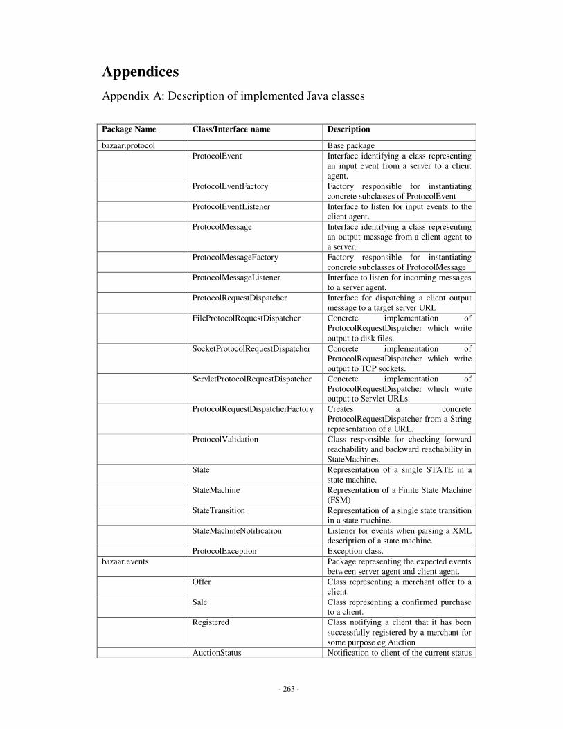
- 263 -
Appendices
Appendix A: Description of implemented Java classes
Package Name Class/Interface name Description
bazaar.protocol Base package
ProtocolEvent Interface identifying a class representing
an input event from a server to a client
agent.
ProtocolEventFactory Factory responsible for instantiating
concrete subclasses of ProtocolEvent
ProtocolEventListener Interface to listen for input events to the
client agent.
ProtocolMessage Interface identifying a class representing
an output message from a client agent to
a server.
ProtocolMessageFactory Factory responsible for instantiating
concrete subclasses of ProtocolMessage
ProtocolMessageListener Interface to listen for incoming messages
to a server agent.
ProtocolRequestDispatcher Interface for dispatching a client output
message to a target server URL
FileProtocolRequestDispatcher Concrete implementation of
ProtocolRequestDispatcher which write
output to disk files.
SocketProtocolRequestDispatcher Concrete implementation of
ProtocolRequestDispatcher which write
output to TCP sockets.
ServletProtocolRequestDispatcher Concrete implementation of
ProtocolRequestDispatcher which write output to Servlet URLs.
ProtocolRequestDispatcherFactory Creates a concrete
ProtocolRequestDispatcher from a String
representation of a URL.
ProtocolValidation Class responsible for checking forward
reachability and backward reachability in
StateMachines.
State Representation of a single STATE in a
state machine.
StateMachine Representation of a Finite State Machine
(FSM)
StateTransition Representation of a single state transition
in a state machine.
StateMachineNotification Listener for events when parsing a XML
description of a state machine.
ProtocolException Exception class.
bazaar.events Package representing the expected events
between server agent and client agent.
Offer Class representing a merchant offer to a
client.
Sale Class representing a confirmed purchase to a client.
Registered Class notifying a client that it has been
successfully registered by a merchant for
some purpose eg Auction
AuctionStatus Notification to client of the current status

- 264 -
of an item being auctioned.
CatalogItems List of items returned to client matching
a previous Catalog query.
VoidEvent Generic event used to initiate the
StateMachine.
bazaar.messages Package representing the expected
messages between client agent and server
agent.
Bid Class representing a client agent’s bid for
an item.
Buy Class representing a client’s purchase of an item.
Catalog Client query of items in merchant
catalog.
Register Client request to register interest with a
merchant.
AuctionInquire Client inquiry on the current status of an
auction item.
VoidMessage Generic message used to end a
StateMachine invocation.
bazaar.parsers Package containing classes and
interfaces responsible for parsing XML
format to Java objects.
StateMachineParser Interface to identify a class as being able
to parse state machine XML.
SAXStateMachineParser Class using SAX to sequentially parse
input XML representing a state machine.
SAXOntologyParser Class using SAX to sequentially parse
input XML representing a hierarchical
ontology for the domain of wine sales.
StateHandler Interface to receive events generated during state machine parsing.
StateParseException Exception class.
bazaar.builder DataDirector Abstract base class for classes
responsible for generating data, as used
in the Builder design pattern.
DataBuilder Abstract base class for classes
responsible for building objects, as in the
Builder design pattern.
ObjectBuilder Default concrete class for object
building.
ObjectDirector Default concrete class for data
generation.
SAXDirector Class responsible for parsing input XML
for tag and attribute data.
CatalogItemsDirector Class for parsing Catalog of items from
server.
ProtocolEventBuilder Class responsible for creating a
recognizable vocabulary phrase as client
input.
ProtocolMessageBuilder Class responsible for creating a recognizable vocabulary phrase as server
input.
XMLItemsBuilder Class for creation of catalog item XML
output from server.
XMLSimpleBuilder Class for creation of XML representing
all other vocabulary phrases. Eg Bid,
Offer, Sale etc.
bazaar.ontology Package containing objects to be used in
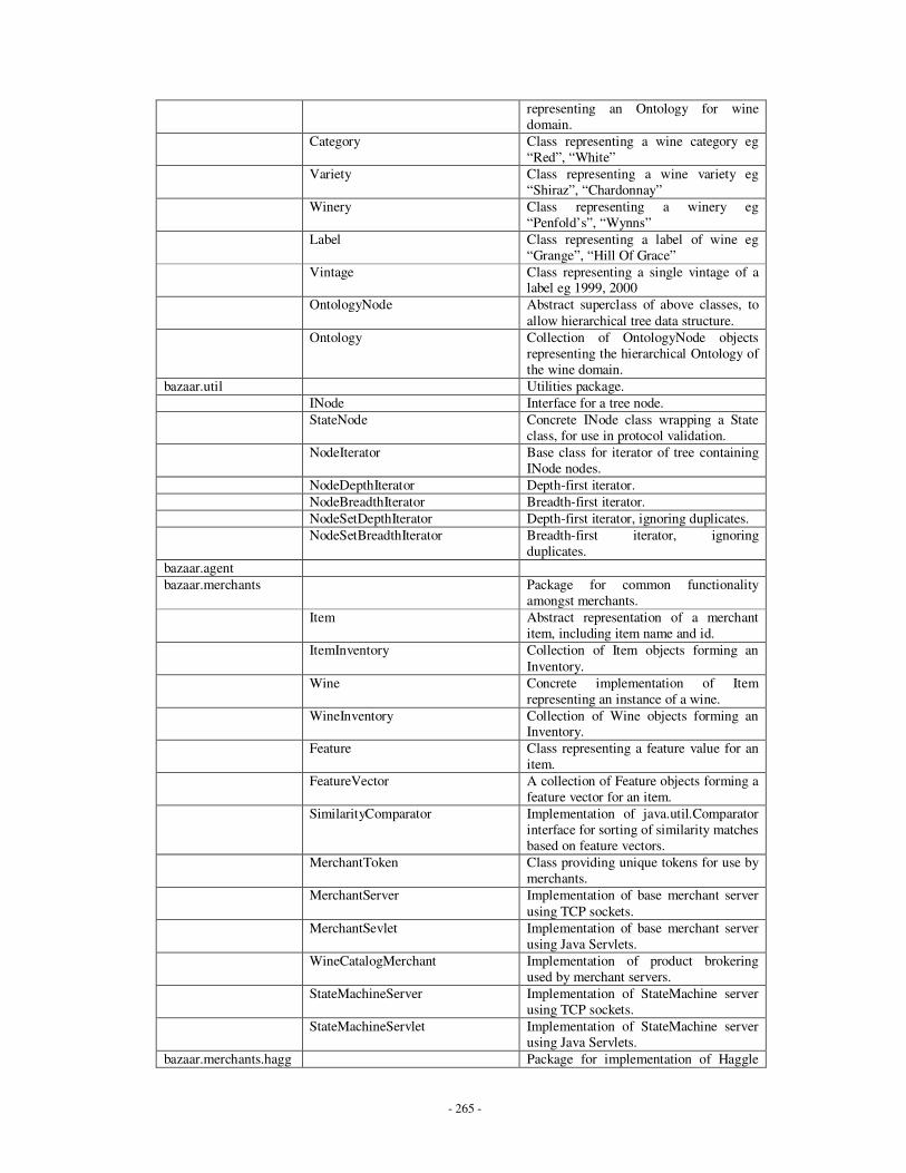
- 265 -
representing an Ontology for wine
domain.
Category Class representing a wine category eg
“Red”, “White”
Variety Class representing a wine variety eg
“Shiraz”, “Chardonnay”
Winery Class representing a winery eg
“Penfold’s”, “Wynns”
Label Class representing a label of wine eg
“Grange”, “Hill Of Grace”
Vintage Class representing a single vintage of a label eg 1999, 2000
OntologyNode Abstract superclass of above classes, to
allow hierarchical tree data structure.
Ontology Collection of OntologyNode objects
representing the hierarchical Ontology of
the wine domain.
bazaar.util Utilities package.
INode Interface for a tree node.
StateNode Concrete INode class wrapping a State
class, for use in protocol validation.
NodeIterator Base class for iterator of tree containing
INode nodes.
NodeDepthIterator Depth-first iterator.
NodeBreadthIterator Breadth-first iterator.
NodeSetDepthIterator Depth-first iterator, ignoring duplicates.
NodeSetBreadthIterator Breadth-first iterator, ignoring
duplicates.
bazaar.agent
bazaar.merchants Package for common functionality
amongst merchants.
Item Abstract representation of a merchant
item, including item name and id.
ItemInventory Collection of Item objects forming an
Inventory.
Wine Concrete implementation of Item
representing an instance of a wine.
WineInventory Collection of Wine objects forming an Inventory.
Feature Class representing a feature value for an
item.
FeatureVector A collection of Feature objects forming a
feature vector for an item.
SimilarityComparator Implementation of java.util.Comparator
interface for sorting of similarity matches
based on feature vectors.
MerchantToken Class providing unique tokens for use by
merchants.
MerchantServer Implementation of base merchant server
using TCP sockets.
MerchantSevlet Implementation of base merchant server
using Java Servlets.
WineCatalogMerchant Implementation of product brokering
used by merchant servers.
StateMachineServer Implementation of StateMachine server
using TCP sockets.
StateMachineServlet Implementation of StateMachine server
using Java Servlets.
bazaar.merchants.hagg Package for implementation of Haggle
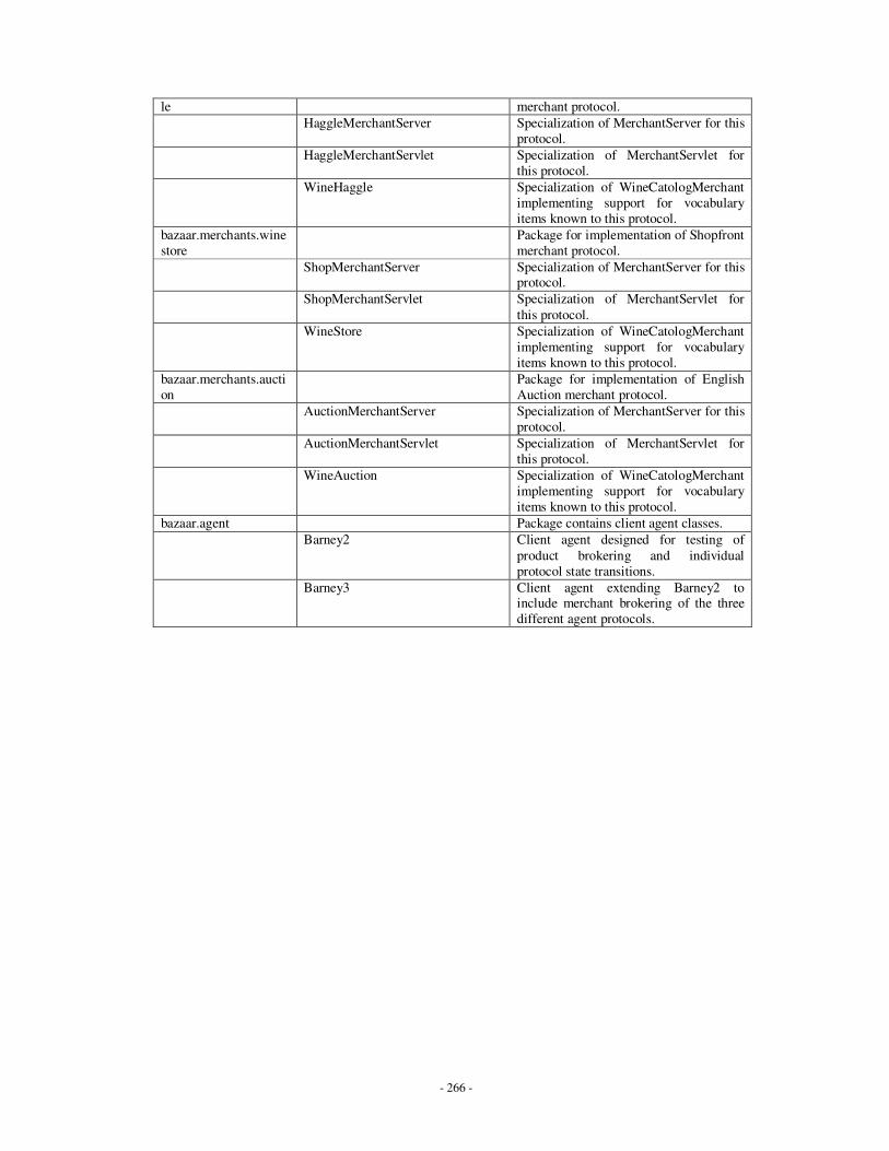
- 266 -
le merchant protocol.
HaggleMerchantServer Specialization of MerchantServer for this
protocol.
HaggleMerchantServlet Specialization of MerchantServlet for
this protocol.
WineHaggle Specialization of WineCatologMerchant
implementing support for vocabulary
items known to this protocol.
bazaar.merchants.wine
store
Package for implementation of Shopfront
merchant protocol.
ShopMerchantServer Specialization of MerchantServer for this protocol.
ShopMerchantServlet Specialization of MerchantServlet for
this protocol.
WineStore Specialization of WineCatologMerchant
implementing support for vocabulary
items known to this protocol.
bazaar.merchants.aucti
on
Package for implementation of English
Auction merchant protocol.
AuctionMerchantServer Specialization of MerchantServer for this
protocol.
AuctionMerchantServlet Specialization of MerchantServlet for
this protocol.
WineAuction Specialization of WineCatologMerchant
implementing support for vocabulary
items known to this protocol.
bazaar.agent Package contains client agent classes.
Barney2 Client agent designed for testing of
product brokering and individual
protocol state transitions.
Barney3 Client agent extending Barney2 to include merchant brokering of the three
different agent protocols.
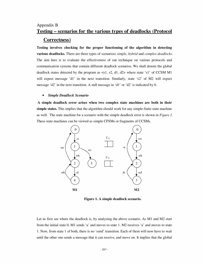
- 267 -
Appendix B
Testing – scenarios for the various types of deadlocks (Protocol
Correctness)
Testing involves checking for the proper functioning of the algorithm in detecting
various deadlocks. There are three types of scenarios: simple, hybrid and complex deadlocks.
The aim here is to evaluate the effectiveness of our technique on various protocols and
communication systems that contain different deadlock scenarios. We shall denote the global
deadlock states detected by the program as <s1, s2, d1, d2> where state ‘s1’ of CCSM M1
will expect message ‘d1’ in the next transition. Similarly, state ‘s2’ of M2 will expect
message ‘d2’ in the next transition. A null message in ‘d1’ or ‘d2’ is indicated by 0.
• Simple Deadlock Scenario
A simple deadlock error arises when two complex state machines are both in their
simple states. This implies that the algorithm should work for any simple finite state machine
as well. The state machine for a scenario with the simple deadlock error is shown in Figure 1.
These state machines can be viewed as simple CFSMs or fragments of CCSMs.
Figure 1. A simple deadlock scenario.
Let us first see where the deadlock is, by analysing the above scenario. As M1 and M2 start
from the initial state 0, M1 sends ‘a’ and moves to state 1. M2 receives ‘a’ and moves to state
1. Now, from state 1 of both, there is no ‘send’ transition. Each of them will now have to wait
until the other one sends a message that it can receive, and move on. It implies that the global
0
4
2
1
3
0
1
2
3
-a
+c
-b +d
+b
+a
-d
+b
+e
M1 M2
+b
-e
C21
C12

- 268 -
state <1, 1> is a simple deadlock. The program output is shown below in Figure 2. The
program starts with determining the output transitional characteristics for all states of M1 and
M2. Only the states with a ‘true’ value are the possible deadlock states. In M1, state 1 and 4
are such states. The program then checks the messages to be desired by these states. For state
1, the expected messages are ‘b’ and ‘c’, whereas for state 4, the expected message is ‘b’.
Now input transitional characteristics are determined for these states. In this case, it is ‘false’
for both the states, as they both have got only ‘sending’ transitions coming towards them.

- 269 -
Figure 2: Program output for the simple deadlock scenario.
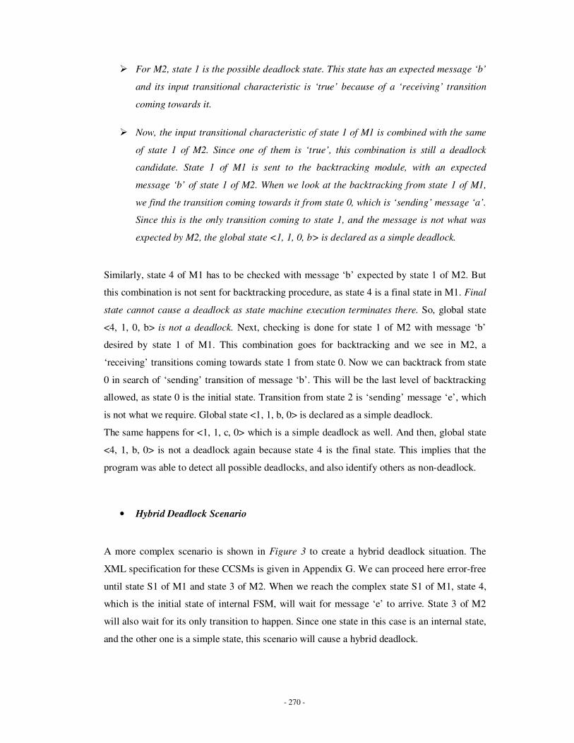
- 270 -
� For M2, state 1 is the possible deadlock state. This state has an expected message ‘b’
and its input transitional characteristic is ‘true’ because of a ‘receiving’ transition
coming towards it.
� Now, the input transitional characteristic of state 1 of M1 is combined with the same
of state 1 of M2. Since one of them is ‘true’, this combination is still a deadlock
candidate. State 1 of M1 is sent to the backtracking module, with an expected
message ‘b’ of state 1 of M2. When we look at the backtracking from state 1 of M1,
we find the transition coming towards it from state 0, which is ‘sending’ message ‘a’.
Since this is the only transition coming to state 1, and the message is not what was
expected by M2, the global state <1, 1, 0, b> is declared as a simple deadlock.
Similarly, state 4 of M1 has to be checked with message ‘b’ expected by state 1 of M2. But
this combination is not sent for backtracking procedure, as state 4 is a final state in M1. Final
state cannot cause a deadlock as state machine execution terminates there. So, global state
<4, 1, 0, b> is not a deadlock. Next, checking is done for state 1 of M2 with message ‘b’
desired by state 1 of M1. This combination goes for backtracking and we see in M2, a
‘receiving’ transitions coming towards state 1 from state 0. Now we can backtrack from state
0 in search of ‘sending’ transition of message ‘b’. This will be the last level of backtracking
allowed, as state 0 is the initial state. Transition from state 2 is ‘sending’ message ‘e’, which
is not what we require. Global state <1, 1, b, 0> is declared as a simple deadlock.
The same happens for <1, 1, c, 0> which is a simple deadlock as well. And then, global state
<4, 1, b, 0> is not a deadlock again because state 4 is the final state. This implies that the
program was able to detect all possible deadlocks, and also identify others as non-deadlock.
• Hybrid Deadlock Scenario
A more complex scenario is shown in Figure 3 to create a hybrid deadlock situation. The
XML specification for these CCSMs is given in Appendix G. We can proceed here error-free
until state S1 of M1 and state 3 of M2. When we reach the complex state S1 of M1, state 4,
which is the initial state of internal FSM, will wait for message ‘e’ to arrive. State 3 of M2
will also wait for its only transition to happen. Since one state in this case is an internal state,
and the other one is a simple state, this scenario will cause a hybrid deadlock.
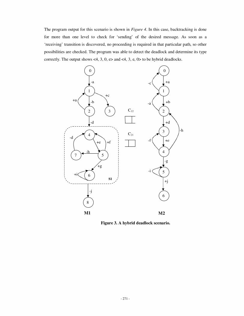
- 271 -
The program output for this scenario is shown in Figure 4. In this case, backtracking is done
for more than one level to check for ‘sending’ of the desired message. As soon as a
‘receiving’ transition is discovered, no proceeding is required in that particular path, so other
possibilities are checked. The program was able to detect the deadlock and determine its type
correctly. The output shows <4, 3, 0, e> and <4, 3, e, 0> to be hybrid deadlocks.
Figure 3. A hybrid deadlock scenario.
0
2
1
3
0
1
2
-a
+c
+d
+b
+a
-d
-b +a
-c
C21
C12
-a
-d
+e +f
-h
+g
S1
4
7
6
5
8
6
-j
+e
-g
+j
4
5
3 -h
-i
-f
M1 M2
+i
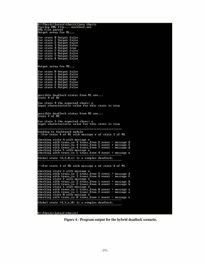
- 272 -
Figure 4 - Program output for the hybrid deadlock scenario.
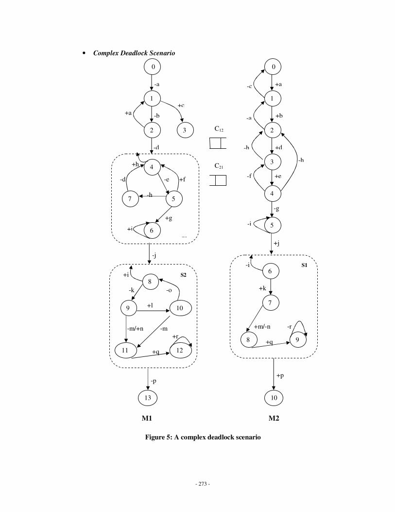
- 273 -
• Complex Deadlock Scenario
Figure 5: A complex deadlock scenario
-i S1
+k
+m/-n -r
+q
0
2
1
3
0
1
2
-a
+c
+d
+b
+a
-d
-b +a
-c
C21
C12
-a
+h
-d -e +f
-h
+g
S1
4
7
6
5
6
-j
+e
-g
+j
4
5
3 -h
-i
-f
M1 M2
+i
9 8
7
+p
10
+i S2
-k -o
+l
-m/+n -m
+r
+q
8
12 11
10 9
13
-p
-h
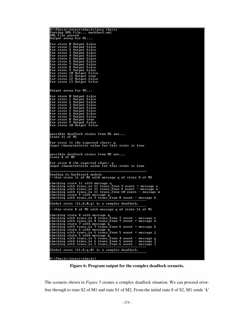
- 274 -
Figure 6: Program output for the complex deadlock scenario.
The scenario shown in Figure 5 creates a complex deadlock situation. We can proceed error-
free through to state S2 of M1 and state S1 of M2. From the initial state 8 of S2, M1 sends ‘k’

- 275 -
and moves to state 9. M2, from the initial state 6 of S1, receives ‘k’ and moves to 7. Now M1
can move to state 11 and M2 can move to state 8. From here, they both expect message ‘q’
from each other and keep waiting for it. Since both these states are internal states, they will
cause a complex deadlock. The program output for this scenario is shown in Figure 6. The
program performs correctly in this scenario as well. The program output shows <11, 8, 0, q>
and <11, 8, q, 0> as complex deadlocks. This implies that the algorithm functions effectively
for all types of deadlocks. Also, when compared to the number of states in each CCSM, our
method explores only a small part of the total state space.

- 276 -
Appendix C: MIDAS Class Diagrams
Figure 1. Package Overview
Figure 2. Package: midas
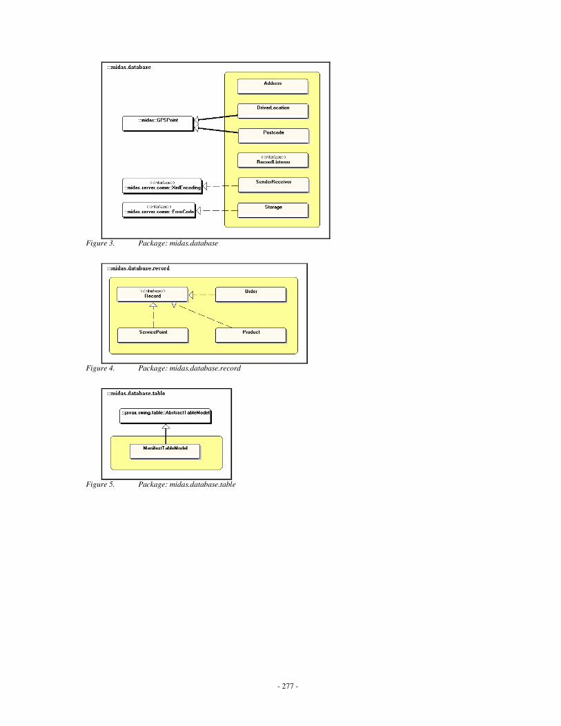
- 277 -
Figure 3. Package: midas.database
Figure 4. Package: midas.database.record
Figure 5. Package: midas.database.table
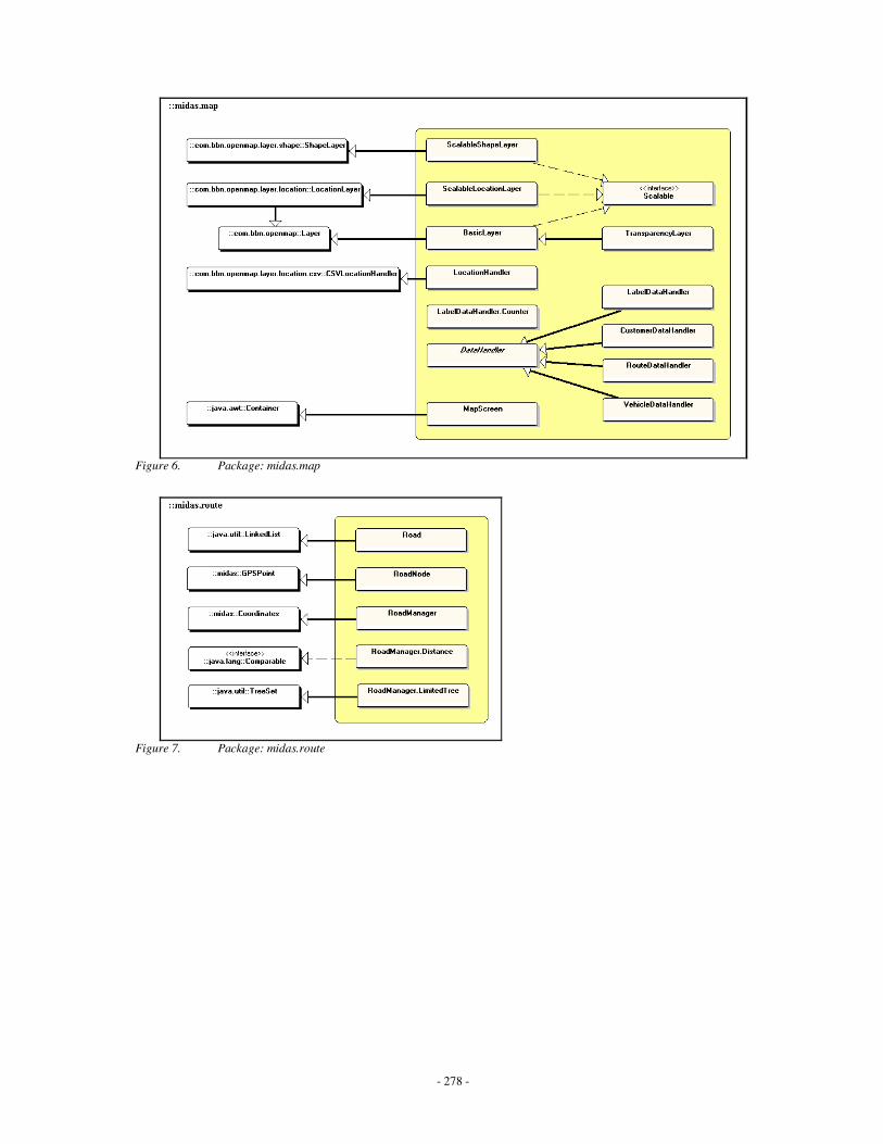
- 278 -
Figure 6. Package: midas.map
Figure 7. Package: midas.route
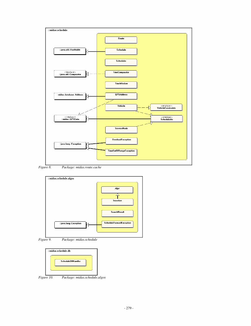
- 279 -
Figure 8. Package: midas.route.cache
Figure 9. Package: midas.schedule
Figure 10. Package: midas.schedule.algos
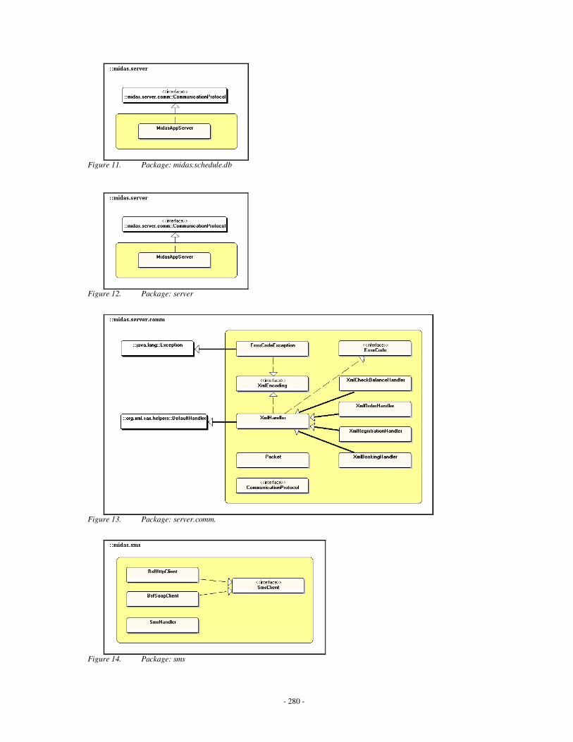
- 280 -
Figure 11. Package: midas.schedule.db
Figure 12. Package: server
Figure 13. Package: server.comm.
Figure 14. Package: sms

- 281 -
Figure 15. Package: ui
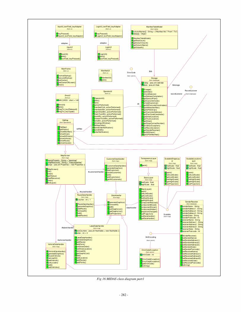
- 282 -
ErrorCode
(from comm)
ErrorCodeException
errorCode : int
ErrorCodeException()
ErrorCodeException()getErrorCode()
toString()
(from comm)
XmlEncoding
(from comm)
SenderReceiver
senderName : String
senderAddress1 : String
senderAddress2 : String
senderAddress3 : String
senderState : StringsenderPostcode : int
receiverName : String
receiverAddress1 : String
receiverAddress2 : String
receiverAddress3 : String
receiverState : String
receiverPostcode : int
SenderReceiver()
setSenderName()
setSenderAddress1()
setSenderAddress2()
setSenderAddress3()setSenderState()
setSenderPostcode()
setReceiverName()
setReceiverAddress1()
setReceiverAddress2()
setReceiverAddress3()
setReceiverState()setReceiverPostcode()
toString()
(from database)
BasicLayer
lowScale : float
highScale : float
Bas icLayer()
paint()setLowScale()
getLowScale()
setHighScale()
getHighScale()
componentRes ized()
componentMoved()
componentShown()componentHidden()
project ionChanged()
setProjec tion()
setDataHandler()
getDataHandler()
(from map)
DataHandler
generateGraphics()
removeAll()
add()setGraphicList()
getGraphicList()
setProjection()
(f rom map)
-dataHandler
Scalable(from map)
ScalableLocationL
ayer
lowScale : float
highScale : float
paint()
setLowScale()
getLowScale()
setHighScale()
getHighScale()
setProjection()
(f rom map)
ScalableShapeLay
er
lowScale : float
highScale : float
paint()
setLowScale()
getLowScale()
setHighScale()
getHighScale()
setProjection()
(from map)
TransparencyLayer
paint()
(from map)
LabelDataHandler
posCounters : java.util.Hashtable = new Hashtable ()
order : int = 0
LabelDataHandler()generateGraphics()
addRoute()
addPoint()
setShowOrder()
setShowLocation()
removeAll()
getGraphicList()add()
addLocation()
addRoutes()
addPoints()
(f rom m ap)
CustomerDataHandler
CustomerDataHandler()
generateGraphics()addCustomer()
locateCustomer()
add()
addCustomers()
getAllCustomers()
(f rom map)
RouteDataHandler
counter : int = 1
RouteDataHandler()
generateGraphics()
addRoute()
removeAll()
add()
addRoutes()
(f rom m ap)
MapScreen
layersProperty : String = "openmap"mapResources : String = "map.properties"
props : java.util.Properties = new Properties ()
MapScreen()init()
clear()
getStatus()
loadResource()
main()
findLayer()
(from map)
#labelsHandler
#customersHandler
#routesHandler
VehicleDataHandler
VehicleDataHandler()
generateGraphics()locateVehicle()
removeAll()
addVehicle()
setLocater()
add()
addVehicles()
(from map)
#vehiclesHandler
InputUI_textField_keyAdapter
keyPressed()
InputUI_textField_keyAdapter()
(from ui)
InputUI
InputUI()
jbInit()
textField_keyPressed()
(from ui )
adaptee
SmsUI
MAX_MSG : short = 140
SmsUI()
jbInit()
msgTxt_keyReleased()
msgTxt_keyTyped()
(from ui )
ManifestUI
ManifestUI()
jbInit()
(from ui )
LoginUI_textField_keyAdapter
keyPressed()
LoginUI_textField_keyAdapter()
(from ui)
LoginUI
LoginUI()
jbInit()
textField_keyPressed()
(from ui )
adaptee
MainFrame
normalStartup()
securedStartup()
setCenter()
setCenterOfScreen()
main()
(from ui )
OpMap
OpMap()
getStatus()
showManifest()
showDriver()
showAllDrivers()
showVehicle()showRoute()
showClosest()
(from OperatorUI)
RecordListener
(f rom d ata base)
ManifestTableModel
columnNames[] : String = {"Manifest No","From","To"}data[][] : Object
ManifestTableModel()
getRowCount()
getColumnCount()
getColumnName()
getValueAt()
(from tabl e)
OperatorUI
OperatorUI()
jbInit()exit()
actionPerformed()
manifestCmb_actionPerformed()
manifestsBtn_actionPerformed()
trackDriverBtn_actionPerformed()
trackTruckBtn_actionPerformed()
routeBtn_actionPerformed()closestTruckBtn_actionPerformed()
smsBtn_actionPerformed()
showInputWindow()
doNewOrder()
sendOrderNotification()
sendSMS()orderNotification()
(from ui )
opMap
Storage
today : java.uti l.Calendar
date : java.uti l.Date
Storage()
addOrder()
checkBalance()
setDeliveryCompletion()
getServicePoint()
getCustomerCode()isValidCustomer()
getAllPostcodeCoordinates()
getAllManifestNos()
getGPS4Driver()
getCustomerAddress()
getPostCodeCoordinate()
getDriverLocation()getTruckLocation()
getDriver()
getDriverContactNumber()
printSQLExcept ion()
setRecordListener()
getSenderReceiver()getAllDrivers()
getGPS4Manifest()
(from database)
recordListener
$db
db
-$storage
Fig 16 MIDAS class diagram part1
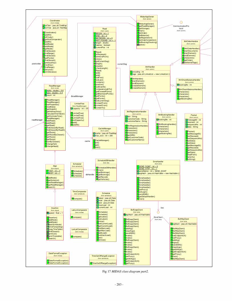
- 283 -
Fig 17 MIDAS class diagram part2.
CommunicationPro
tocol(from comm)
XmlHandler
encoding : int
tags : java.util.LinkedList = new LinkedList ()
XmlHandler()
startElement()
endElement()
createElement()
createElement()
(from comm)
Road
BEGIN : int = 1
END : int = 2
BETWEEN : int = 3
NOT_FOUND : int = - 1
length : double
reverse : boolean
currentPos : int
Road()
isReversed()
isAnEndPoint ()
c lone()
getCurrentSeg()
length()
equals()
checkLength()
Road()
add()
add()
setFi rst ()
setLas t()
contains()
posit ion()
setStartAt()
compareLengthTo()
getForwardPoints()
getBackwardPoints()
getPoints ()
getPoints ()
setCurrentSeg()
convertFrom()
convertFrom()
convertTo()
(f rom rout e)
-currentSeg
SmsHandler
SEND_SOAP : int = 0
SEND_HTTP : int = 1
sendOption : int = SEND_SOAP
argHash : java.util.Hashtable = new Hashtable ()
SmsHandler()
SmsHandler()
SmsHandler()
SmsHandler()
SmsHandler()
setProxy()
setLogin()
sendSMS()
getDefaultHandler()
main()
(f rom sms)
SmsClient(from sms)
-bscBs fSoapCl ient
argHash : java.util.Hashtable
BsfSoapClient()
BsfSoapClient()
BsfSoapClient()
BsfSoapClient()
addArg()
clearArgs()
sendSMS()
invoke()
invoke()
BsfSoapClient()
invoke()
invoke()
BsfSoapClient()
invoke()
invoke()
setEndpointUrl()
setProxy()
getAllArgs()
getEndpointUrl()
getProxy()
(from sms)
BsfHttpClient
argHash : java.util.Hashtable
BsfHttpClient()
BsfHttpClient()
BsfHttpClient()
setEndpointUrl()
setProxy()
addArg()
logout()
sendSMS()
clearArgs()
getAllArgs()
getEndpointUrl()
getProxy()
main()
BsfHttpClient()
(from sms)
Insertion
speed : float = 1
Insertion()
addNode()
addNode()
bestSchdeule()
timeForwarding()
copyTimeTable()
findClosest()
printList()
printTimetable()
search()
(from algos)
Packet
messageID : int
reserved : int
sequenceNo : int
data : String
Packet()
setMessageID()
setReseved()
setSequenceNo()
setData()
setData()
getMessageID()
getReseved()
getSequenceNo()
getData()
readFrom()
writeTo()
toString()
(from comm)
Scheduler
Scheduler()
schedule()
schedule()
(from schedule)
ScheduleDBHandler
ScheduleDBHandler()
main()
getBookings()
getBookings()
getRecord()
getVehicles()
(from db)
-dbHandler
Schedule
latest : java.util.Date
start : java.util.Date
end : java.util.Date
maxLoad : int
currentLoad : int
Schedule()
Schedule()
getLatest()
setLatest()
clone()
setCurrentLoad()
getCurrentLoad()
setMaxLoad()
getMaxLoad()
addLoad()
subtractLoad()
put()
remove()
(from schedule)
TimeComparator
compare()
(from schedu le )
TimeOutOfRangeExcept ion
TimeOutOfRangeException()
(from schedule)
LimitedTree
capaci ty : int = 25
LimitedTree()
LimitedTree()
LimitedTree()
setCapacity()
add()
addAll()
(from RoadManager)
LatLonComparator
compare()
(f rom m idas)
LonLatComparator
compare()
(f rom m idas)
DateFormatException
DateFormatException()
DateFormatException()
(from midas)
Coordinates
latTree : java.util .TreeMap
lonTree : java.uti l.TreeMap
Coordinates()
addAll()
isEmpty()
getSubComparator()
addAll()
addNode()
addNode()
getNode()
findClosest()
findRange()
findClosest()
getPoints()
findClosest()
previousKey()
nextKey()
findRange()
distance()
simDistance()
(f rom midas)
Algo
FAST : int = 0
BEST : int = 1
addNode()
getInstance()
setRoadManager()
getRoadManager()
search()
(from algos)
CacheManager
cache : java.util.TreeMap
max_size : int = 200
CacheManager()
put()
get()
evict()
(f rom cache )
postcodes
XmlBookingHandler
bookingNo : int
XmlBookingHandler()
characters()
characters()
characters()
getBookingNo()
(from comm)
XmlCheckBalanceHandler
bookingNo : int
XmlCheckBalanceHandler()
characters()
characters()
characters()
getBookingNo()
(f rom comm)
XmlRegistrationHandler
abn : String
customerCode : String
customerName : String
XmlRegistrationHandler()
characters()
characters()
characters()
getABN()
getCustomerCode()
getCustomerName()
(from comm)
RoadManager
alpha : double = 0.6
beta : double = 0.4
count : int
RoadManager()
RoadManager()
setProperties()
readData()
getAngleA()
getIntersections()
calculateTimeTaken()
getEstimateTime()
RoadManager()
addRoad()
addRoad()
getRoad()
findClosestByRoad()
findClosestByRoad2()
getRoute()
getRouteByClosest()
getRoute()
getRoute()
sortByClosest()
changeTail()
changeHead()
(from ro ute)
-cache
roadManager
MidasAppServer
MidasAppServer()
getRoadManager()
getStorage()
main()
doOrder()
doBalance()
doRegistration()
doOrderCompletion()
doBook ingChecking()
parse()
(from server)
-$roadManager
XmlOrderHandler
XmlOrderHandler()
startDocument()
startElement()
endElement()
characters()
getOrder()
doInternalTags()
(from comm)
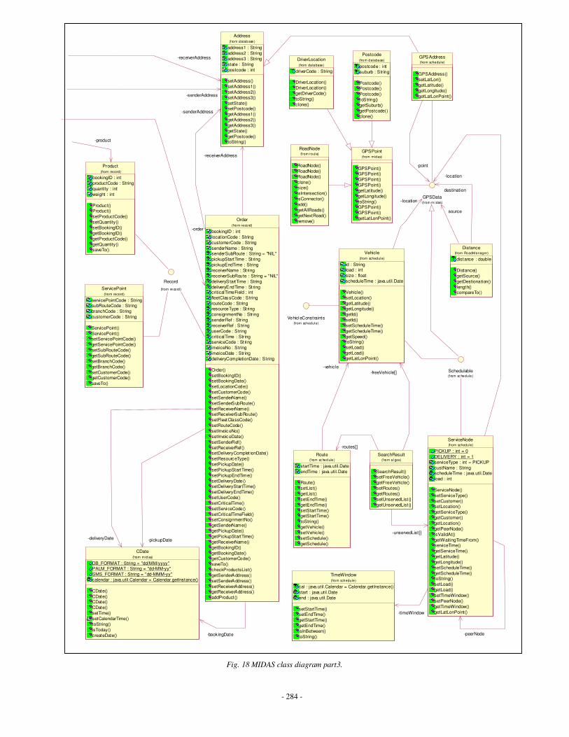
- 284 -
DriverLocation
driverCode : String
DriverLocation()
DriverLocation()
getDriverCode()
toString()
clone()
(from database)
Postcode
postcode : int
suburb : S tring
Postcode()Postcode()
Postcode()
toS tring()
getSuburb()
getPostcode()
clone()
(from database)
Record
(from re cord)ServicePoint
servicePointCode : StringsubRouteCode : String
branchCode : String
customerCode : String
ServicePoint()
ServicePoint()setServicePointCode()
getServicePointCode()
setSubRouteCode()
getSubRouteCode()
setBranchCode()
getBranchCode()
setCustomerCode()getCustomerCode()
saveTo()
(from record)
RoadNode
RoadNode()
RoadNode()
RoadNode()
clone()size()
isIntersection()
isConnector()
add()
getAllRoads()
getNextRoad()
remove()
(f rom rout e)GPSPoint
GPSPoint()GPSPoint()
GPSPoint()
GPSPoint()
getLatitude()
getLongitude()
toString()GPSPoint()
GPSPoint()
getLatLonPoint()
(from midas)
Schedulable(f rom sc hedule )
VehicleConstraints(from schedule)
Product
bookingID : int
productCode : String
quantity : int
weight : int
Product()Product()
setProductCode()
setQuantity()
setBookingID()
getBookingID()
getProductCode()
getQuantity()saveTo()
(from record)
Address
address1 : String
address2 : String
address3 : String
state : String
postcode : int
setAddress()
setAddress1()
setAddress2()
setAddress3()
setState()setPostcode()
getAddress1()
getAddress2()
getAddress3()
getState()
getPostcode()toString()
(f rom datab ase )
-senderAddress
-receiverAddress
-product
Order
bookingID : int
locationCode : String
customerCode : String
senderName : StringsenderSubRoute : String = "NIL"
pickupStartTime : St ring
pickupEndTime : String
receiverName : St ring
receiverSubRoute : String = "NIL"
deliveryS tartTime : String
deliveryEndTime : St ringcriticalTimeField : int
fleetClas sCode : S tring
routeCode : StringresourceType : St ring
consignmentNo : String
senderRef : String
receiverRef : S tring
userCode : String
criticalTime : StringserviceCode : St ring
invoiceNo : String
invoiceDate : String
deliveryCompletionDate : String
Order()
setBookingID()setBookingDate()
setLocationCode()
setCustomerCode()
setSenderName()
setSenderSubRoute()
setReceiverName()setReceiverSubRoute()
setFleetClassCode()
setRouteCode()
setInvoic eNo()
setInvoic eDate()
setSenderRef()
setReceiverRef()setDeliveryComplet ionDate()
setResourc eType()
setPickupDate()
setPickupStartTime()
setPickupEndTime()
setDeliveryDate()setDeliveryStartTime()
setDeliveryEndTime()
setUserCode()
setCriticalTime()
setServiceCode()
setCriticalTimeField()setConsignmentNo()
getSenderName()
getPickupDate()
getPickupStartTime()
getReceiverName()
getBookingID()
getBookingDate()getCustomerCode()
saveTo()
checkProductsList()
getSenderAddress()
setSenderAddress()
setReceiverAddress()getReceiverAddress()
addProduct()
(f ro m reco rd)
-senderAddress
-receiverAddress
-order
CDate
DB_FORMAT : String = "dd/MM/yyyy"PALM_FORMAT : String = "dd-MM-yy"
SMS_FORMAT : String = "dd-MMM-yy"
calendar : java.util.Calendar = Calendar.getInstance()
CDate()
CDate()CDate()
CDate()
setTime()
setCalendarTime()
toString()
isToday()
createDate()
(f rom m id as)
-book ingDate
-pickupDate-deliveryDate
TimeWindow
cal : java.util.Calendar = Calendar.getInstance()
start : java.util.Date
end : java.util.Date
setStartTime()setEndTime()
getStartTime()
getEndTime()
isInBetween()
toString()
(from schedule)
Route
startTime : java.util.Date
endTime : java.util.Date
Route()
setList()
getList()
setEndTime()
getEndTime()
setStartTime()getStartTime()
toString()
getVehicle()
setVehicle()
setSchedule()
getSchedule()
(f rom sc hed ule )
SearchResult
SearchResult()setFreeVehicle()
getFreeVehicle()
setRoutes()
getRoutes()
setUnservedList ()
getUnservedList ()
(f rom al gos)
-routes[]
ServiceNode
PICKUP : int = 0
DELIVERY : int = 1
serviceType : int = PICKUP
custName : StringscheduleTime : java.util.Date
load : int
ServiceNode()
setServiceType()
setCustomer()setLocation()
getServiceType()
getCustomer()
getLocation()
getPeerNode()
isValidAt()
getWaitingTimeFrom()serviceTime()
getServiceTime()
getLatitude()
getLongitude()
setScheduleTime()
getScheduleTime()toString()
setLoad()
getLoad()
setTimeWindow()
setPeerNode()
getTimeWindow()
getLatLonPoint()
(from schedule)
-peerNode
-timeWindow
-unservedList[]
Vehicle
id : Stringload : int
size : float
scheduleTime : java.util.Date
Vehicle()
setLocation()
getLatitude()getLongitude()
getId()
setId()
setScheduleTime()
getScheduleTime()
getSpeed()toString()
setLoad()
getLoad()getLatLonPoint()
(from schedule)
-vehicle
-freeVehicle[]
Distance
distance : double
Distance()
getSource()
getDestionation()
length()compareTo()
(from RoadManager)
GPSAddress
GPSAddress()
setLatLon()
getLatitude()
getLongitude()
getLatLonPoint()
(from schedule)
GPSData(f rom m idas)
-location
-location
source
destination
-point
Fig. 18 MIDAS class diagram part3.
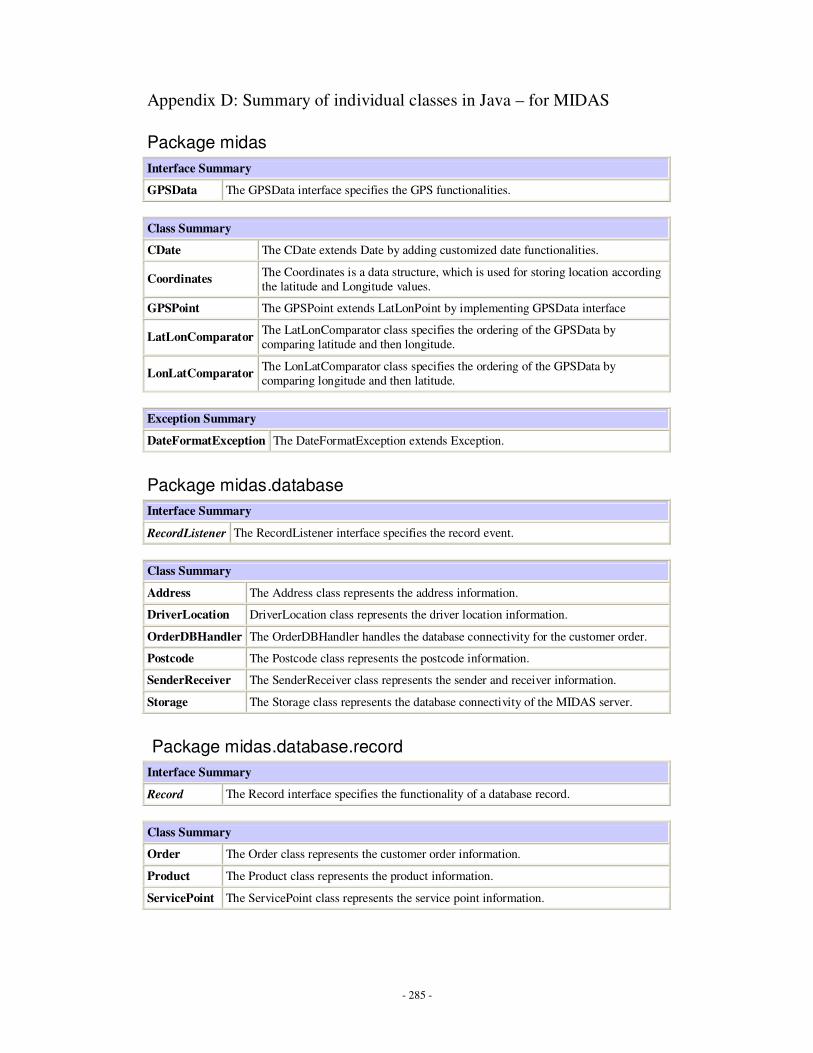
- 285 -
Appendix D: Summary of individual classes in Java – for MIDAS
Package midas
Interface Summary
GPSData The GPSData interface specifies the GPS functionalities.
Class Summary
CDate The CDate extends Date by adding customized date functionalities.
Coordinates The Coordinates is a data structure, which is used for storing location according
the latitude and Longitude values.
GPSPoint The GPSPoint extends LatLonPoint by implementing GPSData interface
LatLonComparator The LatLonComparator class specifies the ordering of the GPSData by
comparing latitude and then longitude.
LonLatComparator The LonLatComparator class specifies the ordering of the GPSData by
comparing longitude and then latitude.
Exception Summary
DateFormatException The DateFormatException extends Exception.
Package midas.database
Interface Summary
RecordListener The RecordListener interface specifies the record event.
Class Summary
Address The Address class represents the address information.
DriverLocation DriverLocation class represents the driver location information.
OrderDBHandler The OrderDBHandler handles the database connectivity for the customer order.
Postcode The Postcode class represents the postcode information.
SenderReceiver The SenderReceiver class represents the sender and receiver information.
Storage The Storage class represents the database connectivity of the MIDAS server.
Package midas.database.record
Interface Summary
Record The Record interface specifies the functionality of a database record.
Class Summary
Order The Order class represents the customer order information.
Product The Product class represents the product information.
ServicePoint The ServicePoint class represents the service point information.
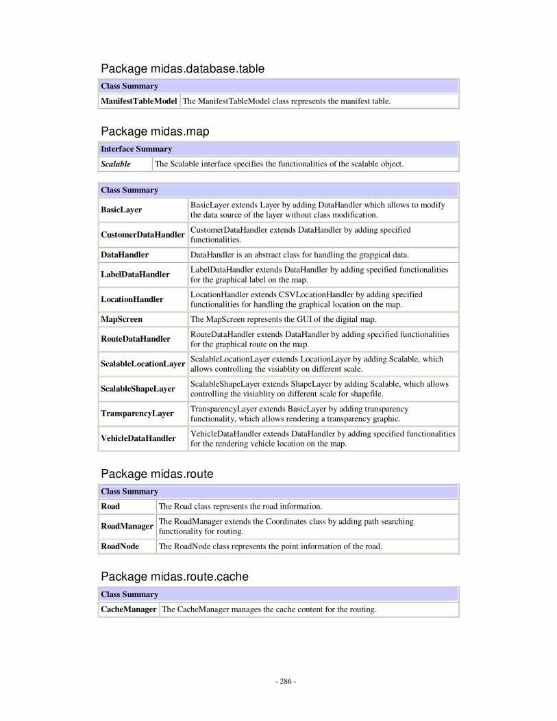
- 286 -
Package midas.database.table
Class Summary
ManifestTableModel The ManifestTableModel class represents the manifest table.
Package midas.map
Interface Summary
Scalable The Scalable interface specifies the functionalities of the scalable object.
Class Summary
BasicLayer BasicLayer extends Layer by adding DataHandler which allows to modify
the data source of the layer without class modification.
CustomerDataHandler CustomerDataHandler extends DataHandler by adding specified
functionalities.
DataHandler DataHandler is an abstract class for handling the grapgical data.
LabelDataHandler LabelDataHandler extends DataHandler by adding specified functionalities
for the graphical label on the map.
LocationHandler LocationHandler extends CSVLocationHandler by adding specified
functionalities for handling the graphical location on the map.
MapScreen The MapScreen represents the GUI of the digital map.
RouteDataHandler RouteDataHandler extends DataHandler by adding specified functionalities
for the graphical route on the map.
ScalableLocationLayer ScalableLocationLayer extends LocationLayer by adding Scalable, which
allows controlling the visiablity on different scale.
ScalableShapeLayer ScalableShapeLayer extends ShapeLayer by adding Scalable, which allows
controlling the visiablity on different scale for shapefile.
TransparencyLayer TransparencyLayer extends BasicLayer by adding transparency
functionality, which allows rendering a transparency graphic.
VehicleDataHandler VehicleDataHandler extends DataHandler by adding specified functionalities
for the rendering vehicle location on the map.
Package midas.route
Class Summary
Road The Road class represents the road information.
RoadManager The RoadManager extends the Coordinates class by adding path searching
functionality for routing.
RoadNode The RoadNode class represents the point information of the road.
Package midas.route.cache
Class Summary
CacheManager The CacheManager manages the cache content for the routing.
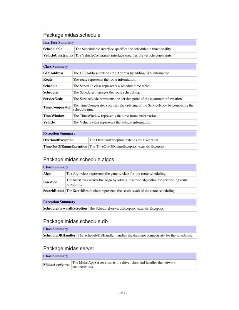
- 287 -
Package midas.schedule
Interface Summary
Schedulable The Schedulable interface specifies the schedulable functionality.
VehicleConstraints The VehicleConstraints interface specifies the vehicle constraints.
Class Summary
GPSAddress The GPSAddress extends the Address by adding GPS infomation.
Route The route represents the route information.
Schedule The Schedule class represents a schedule time table.
Scheduler The Scheduler manages the route scheduling.
ServiceNode The ServiceNode represents the service point of the customer information.
TimeComparator The TimeComparator specifies the ordering of the ServiceNode by comparing the schedule time.
TimeWindow The TimeWindow represents the time frame information.
Vehicle The Vehicle class represents the vehicle information.
Exception Summary
OverloadException The OverloadException extends the Exception.
TimeOutOfRangeException The TimeOutOfRangeException extends Exception.
Package midas.schedule.algos
Class Summary
Algo The Algo cless represents the generic class for the route scheduling.
Insertion The Insertion extends the Algo by adding Insertion algorithm for performing route
scheduling.
SearchResult The SearchResult class represents the seach result of the route scheduling.
Exception Summary
ScheduleForwardException The ScheduleForwardException extends Exception.
Package midas.schedule.db
Class Summary
ScheduleDBHandler The ScheduleDBHandler handles the database connectivity for the scheduling.
Package midas.server
Class Summary
MidasAppServer The MidasAppServer class is the driver class and handles the network
connectivities.
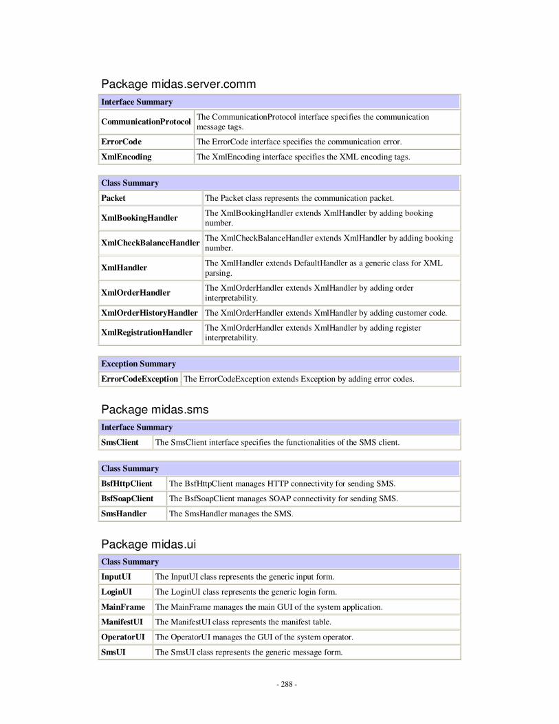
- 288 -
Package midas.server.comm
Interface Summary
CommunicationProtocol The CommunicationProtocol interface specifies the communication
message tags.
ErrorCode The ErrorCode interface specifies the communication error.
XmlEncoding The XmlEncoding interface specifies the XML encoding tags.
Class Summary
Packet The Packet class represents the communication packet.
XmlBookingHandler The XmlBookingHandler extends XmlHandler by adding booking
number.
XmlCheckBalanceHandler The XmlCheckBalanceHandler extends XmlHandler by adding booking
number.
XmlHandler The XmlHandler extends DefaultHandler as a generic class for XML
parsing.
XmlOrderHandler The XmlOrderHandler extends XmlHandler by adding order
interpretability.
XmlOrderHistoryHandler The XmlOrderHandler extends XmlHandler by adding customer code.
XmlRegistrationHandler The XmlOrderHandler extends XmlHandler by adding register
interpretability.
Exception Summary
ErrorCodeException The ErrorCodeException extends Exception by adding error codes.
Package midas.sms
Interface Summary
SmsClient The SmsClient interface specifies the functionalities of the SMS client.
Class Summary
BsfHttpClient The BsfHttpClient manages HTTP connectivity for sending SMS.
BsfSoapClient The BsfSoapClient manages SOAP connectivity for sending SMS.
SmsHandler The SmsHandler manages the SMS.
Package midas.ui
Class Summary
InputUI The InputUI class represents the generic input form.
LoginUI The LoginUI class represents the generic login form.
MainFrame The MainFrame manages the main GUI of the system application.
ManifestUI The ManifestUI class represents the manifest table.
OperatorUI The OperatorUI manages the GUI of the system operator.
SmsUI The SmsUI class represents the generic message form.
- 289 -
Appendix E: Communications packet data structure A communication message consists of message ID, reserved field, sequence number and
data.
Message ID is a positive number in 8 bits size, it must be one of the following pre-defined
value:
− 0 : new order
− 1 : check invoice balance
− 2 : registration validation
− 3 : order completion
− 4 : check booking
− 200 : reply
− 250 : error
Reserved field is 8 bits reserved size for future usage.
Sequence number is a positive number with incremental value during a communication
session.
Data is the exchanged information, which is presented in XML format.

- 290 -
Appendix F: Class diagrams
Client Implementation
Figure 1 – Client Implementation Class diagram
Observable
StateMachine
ProtocolMessage fireEvent(protocolEvent)
changeState(State)
ProtocolEventListener
ProtocolMessage CreateMessage(ProtocolEvent) 11State
1..n1..n
ProtocolEvent11
ProtocolMessageStateTransition
1..n1..n11
11
Barney
11
InputStreamOutputStream
ProtocolRequestDispatcher
sendMessage(ProtocolMessage)
ProtocolEvent receiveEvent()11
11
11
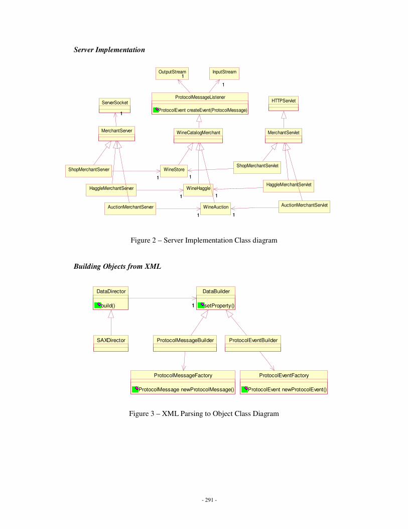
- 291 -
Server Implementation
Figure 2 – Server Implementation Class diagram
Building Objects from XML
Figure 3 – XML Parsing to Object Class Diagram
WineCatalogMerchant
InputStream
ProtocolMessageListener
ProtocolEvent createEvent(ProtocolMessage)
1
OutputStream11
1
ShopMerchantServer
HaggleMerchantServer
AuctionMerchantServer
MerchantServlet
ShopMerchantServletWineStore
11 11
HaggleMerchantServletWineHaggle
11 11
AuctionMerchantServletWineAuction
11 11
HTTPServlet
MerchantServer
ServerSocket
11
SAXDirector
DataDirector
build()
DataBuilder
setProperty()11
ProtocolMessageBuilder
ProtocolMessageFactory
ProtocolMessage newProtocolMessage()
ProtocolEventBuilder
ProtocolEventFactory
ProtocolEvent newProtocolEvent()
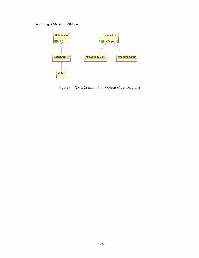
- 292 -
Building XML from Objects
Figure 4 – XML Creation from Objects Class Diagrams
DataDirector
build()
DataBuilder
setProperty()11
XMLSimpleBuilder XMLItemsBuilderObjectDirector
Object11

- 293 -
Appendix G: XML listings
Chapter 2 – State Machine definitions
• Haggle Protocol <?xml version="1.0"?>
<!DOCTYPE StateMachine [
<!ELEMENT StateMachine (State+)>
<!ELEMENT State (StateTransition+)>
<!ATTLIST State name CDATA #REQUIRED>
<!ATTLIST State final CDATA #IMPLIED>
<!ELEMENT StateTransition (event,message,transition)>
<!ELEMENT event (#PCDATA)>
<!ATTLIST event dtd CDATA #IMPLIED>
<!ELEMENT message (#PCDATA)>
<!ATTLIST message url CDATA #IMPLIED>
<!ATTLIST message dtd CDATA #IMPLIED>
<!ELEMENT transition (#PCDATA)>
]>
<StateMachine>
<State name="IDLE" final="true">
<StateTransition>
<event>Void</event>
<message url="yallara:28039" dtd="Catalog.dtd">Catalog</message>
<transition>CATALOG</transition>
</StateTransition>
</State>
<State name="CATALOG">
<StateTransition>
<event dtd="CatalogItems.dtd">CatalogItems</event>
<message>Void</message>
<transition>IDLE</transition>
</StateTransition>
<StateTransition>
<event dtd="CatalogItems.dtd">CatalogItems</event>
<message url="yallara:28039" dtd="Catalog.dtd">Catalog</message>

- 294 -
<transition>CATALOG</transition>
</StateTransition>
<StateTransition>
<event dtd="CatalogItems.dtd">CatalogItems</event>
<message url="yallara:28039" dtd="Bid.dtd">Bid</message>
<transition>BIDDING</transition>
</StateTransition>
</State>
<State name="BIDDING">
<StateTransition>
<event dtd="Offer.dtd">Offer</event>
<message url="yallara:28039" dtd="Buy.dtd">Buy</message>
<transition>BUYING</transition>
</StateTransition>
<StateTransition>
<event dtd="Offer.dtd">Offer</event>
<message url="yallara:28039" dtd="Bid.dtd">Bid</message>
<transition>BIDDING</transition>
</StateTransition>
<StateTransition>
<event dtd="Offer.dtd">Offer</event>
<message>Void</message>
<transition>IDLE</transition>
</StateTransition>
<StateTransition>
<event dtd="Sale.dtd">Sale</event>
<message>Void</message>
<transition>IDLE</transition>
</StateTransition>
</State>
<State name="BUYING">
<StateTransition>
<event dtd="Sale.dtd">Sale</event>
<message>Void</message>
<transition>IDLE</transition>
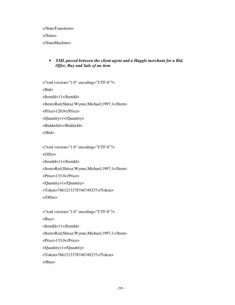
- 295 -
</StateTransition>
</State>
</StateMachine>
• XML passed between the client agent and a Haggle merchant for a Bid,
Offer, Buy and Sale of an item
<?xml version="1.0" encoding="UTF-8"?>
<Bid>
<ItemId>11</ItemId>
<Item>Red;Shiraz;Wynns;Michael;1997;1</Item>
<Price>120.0</Price>
<Quantity>1</Quantity>
<BidderId></BidderId>
</Bid>
<?xml version="1.0" encoding="UTF-8"?>
<Offer>
<ItemId>11</ItemId>
<Item>Red;Shiraz;Wynns;Michael;1997;1</Item>
<Price>133.0</Price>
<Quantity>1</Quantity>
<Token>7661213378746749237</Token>
</Offer>
<?xml version="1.0" encoding="UTF-8"?>
<Buy>
<ItemId>11</ItemId>
<Item>Red;Shiraz;Wynns;Michael;1997;1</Item>
<Price>133.0</Price>
<Quantity>1</Quantity>
<Token>7661213378746749237</Token>
</Buy>
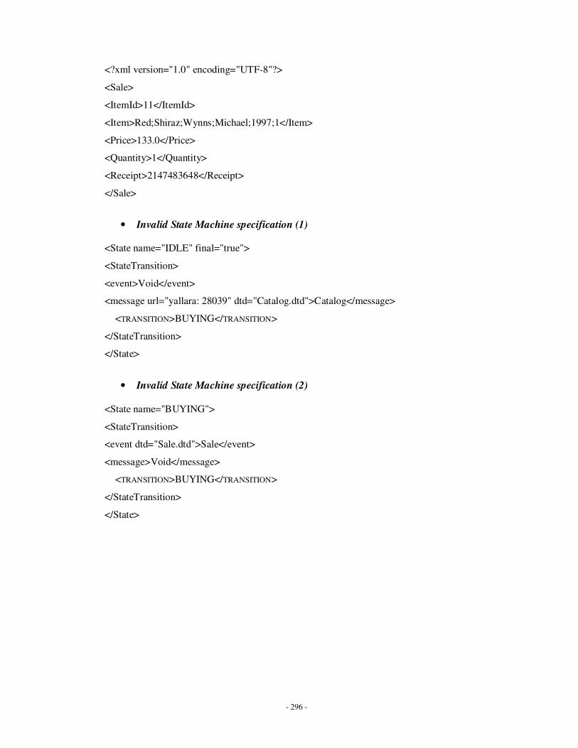
- 296 -
<?xml version="1.0" encoding="UTF-8"?>
<Sale>
<ItemId>11</ItemId>
<Item>Red;Shiraz;Wynns;Michael;1997;1</Item>
<Price>133.0</Price>
<Quantity>1</Quantity>
<Receipt>2147483648</Receipt>
</Sale>
• Invalid State Machine specification (1) <State name="IDLE" final="true">
<StateTransition>
<event>Void</event>
<message url="yallara: 28039" dtd="Catalog.dtd">Catalog</message>
<TRANSITION>BUYING</TRANSITION>
</StateTransition>
</State>
• Invalid State Machine specification (2) <State name="BUYING">
<StateTransition>
<event dtd="Sale.dtd">Sale</event>
<message>Void</message>
<TRANSITION>BUYING</TRANSITION>
</StateTransition>
</State>
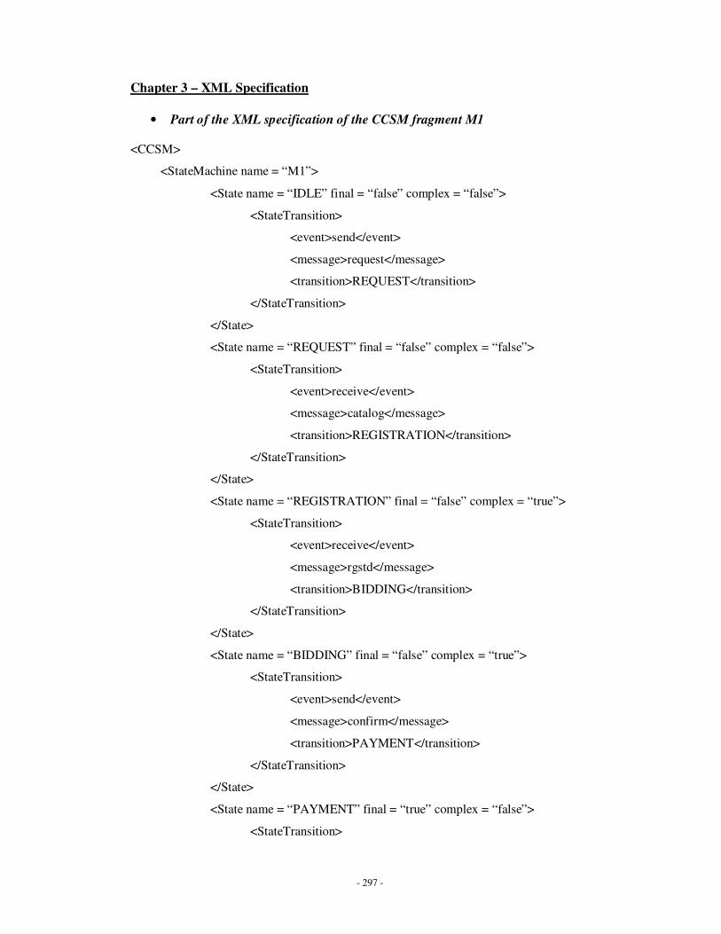
- 297 -
Chapter 3 – XML Specification
• Part of the XML specification of the CCSM fragment M1 <CCSM>
<StateMachine name = “M1”>
<State name = “IDLE” final = “false” complex = “false”>
<StateTransition>
<event>send</event>
<message>request</message>
<transition>REQUEST</transition>
</StateTransition>
</State>
<State name = “REQUEST” final = “false” complex = “false”>
<StateTransition>
<event>receive</event>
<message>catalog</message>
<transition>REGISTRATION</transition>
</StateTransition>
</State>
<State name = “REGISTRATION” final = “false” complex = “true”>
<StateTransition>
<event>receive</event>
<message>rgstd</message>
<transition>BIDDING</transition>
</StateTransition>
</State>
<State name = “BIDDING” final = “false” complex = “true”>
<StateTransition>
<event>send</event>
<message>confirm</message>
<transition>PAYMENT</transition>
</StateTransition>
</State>
<State name = “PAYMENT” final = “true” complex = “false”>
<StateTransition>
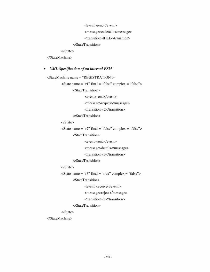
- 298 -
<event>send</event>
<message>ccdetails</message>
<transition>IDLE</transition>
</StateTransition>
</State>
</StateMachine>
• XML Specification of an internal FSM
<StateMachine name = “REGISTRATION”>
<State name = “r1” final = “false” complex = “false”>
<StateTransition>
<event>send</event>
<message>request</message>
<transition>r2</transition>
</StateTransition>
</State>
<State name = “r2” final = “false” complex = “false”>
<StateTransition>
<event>send</event>
<message>details</message>
<transition>r3</transition>
</StateTransition>
</State>
<State name = “r3” final = “true” complex = “false”>
<StateTransition>
<event>receive</event>
<message>reject</message>
<transition>r1</transition>
</StateTransition>
</State>
</StateMachine>
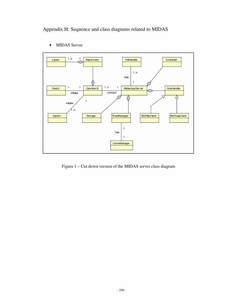
- 299 -
Appendix H: Sequence and class diagrams related to MIDAS
• MIDAS Server
Figure 1 – Cut down version of the MIDAS server class diagram
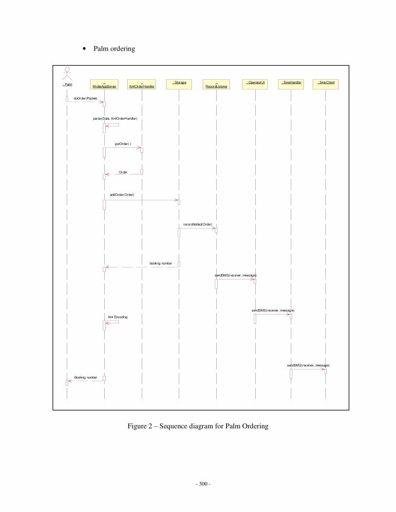
- 300 -
• Palm ordering
Figure 2 – Sequence diagram for Palm Ordering
: SmsHandler : Palm
:
MidasAppServer
:
XmlOrderHandler
: Storage :
RecordListener
: OperatorUI : SmsClient
doOrder(Packet)
parse(Data, XmlOrderHandler)
getOrder( )
addOrder(Order)
Order
recordAdded(Order)
sendSMS(recviver, message)
sendSMS(receiver, message)
booking number
Xml Encoding
Booking number
sendSMS(receiver, message)
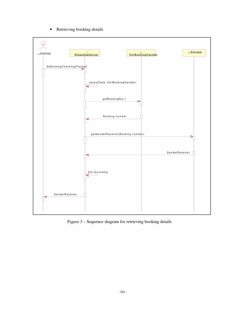
- 301 -
• Retrieving booking details
Figure 3 – Sequence diagram for retrieving booking details
: In te rn e t : M id a s A p p S e rv e r
: X m lB o o k in g H a n d le r
: S to ra g e
d o B o o k in g C h e c k in g (P a c k e t)
p a rs e (D a ta , X m lB o o k in g H a n d le r)
g e tB o o k in g N o ( )
B o o k in g n u m b e r
g e tS e n d e rR e c e iv e r(B o o k in g n u m b e r )
S e n d e rR ec e iv e r
X m l E n c o d in g
S e n d e rR e c e iv e r
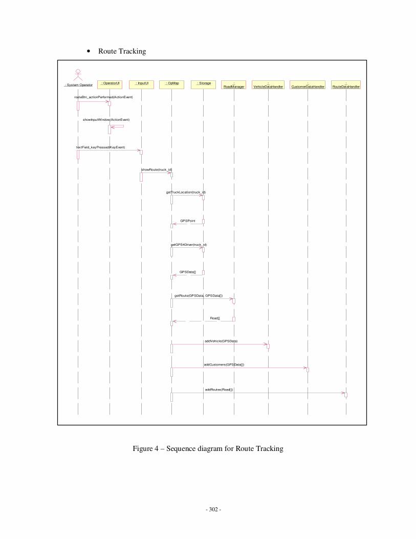
- 302 -
• Route Tracking
Figure 4 – Sequence diagram for Route Tracking
: System Operator : OperatorUI : InputUI : OpMap : Storage :
RoadManager :
VehicleDataHandler :
CustomerDataHandler :
RouteDataHandler
routeBtn_actionPerformed(ActionEvent)
showInputWindow(ActionEvent)
textField_keyPressed(KeyEvent)
showRoute(truck_id)
getTruckLocation(truck_id)
GPSPoint
addVehicle(GPSData)
getGPS4Driver(truck_id)
GPSData[]
getRoute(GPSData, GPSData[])
Road[]
addCustomers(GPSData[])
addRoutes(Road[])
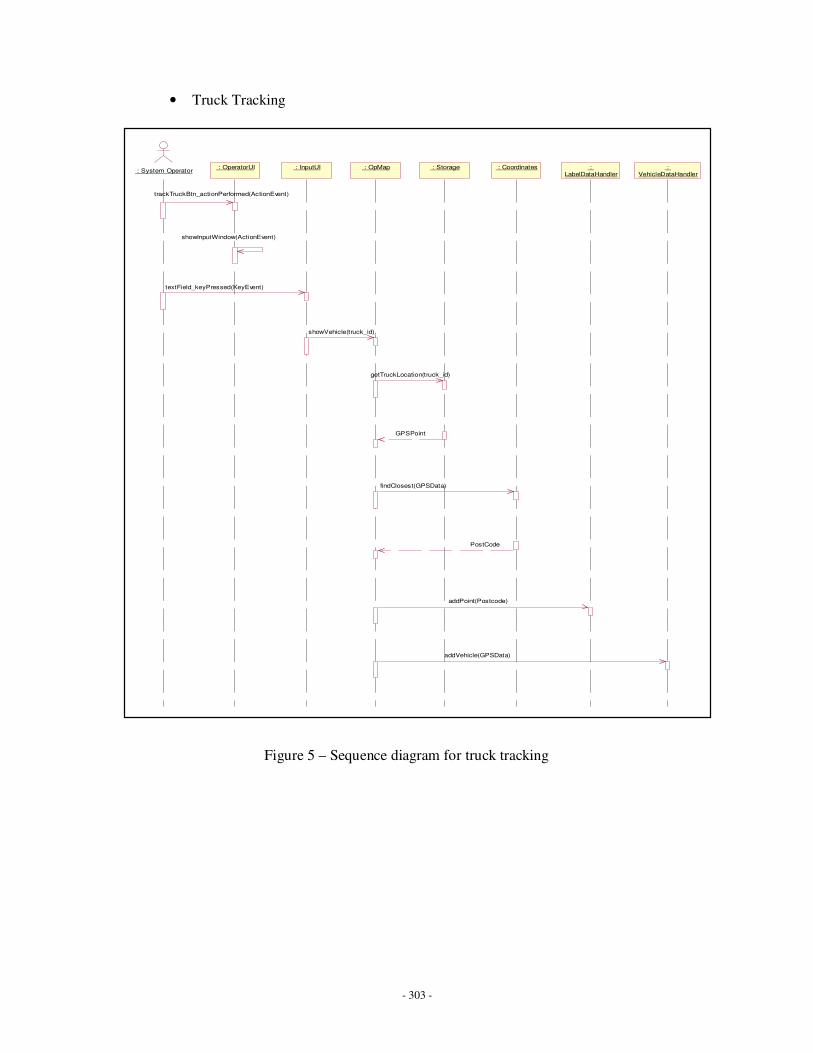
- 303 -
• Truck Tracking
Figure 5 – Sequence diagram for truck tracking
: System Operator : OperatorUI : InputUI : OpMap : Storage : Coordinates :
LabelDataHandler
:
VehicleDataHandler
trackTruckBtn_actionPerformed(ActionEvent)
showInputWindow(ActionEvent)
textField_keyPressed(KeyEvent)
showVehicle(truck_id)
getTruckLocation(truck_id)
GPSPoint
addPoint(Postcode)
findClosest(GPSData)
PostCode
addVehicle(GPSData)
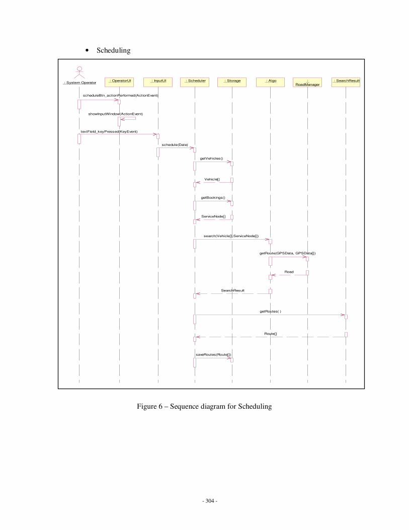
- 304 -
• Scheduling
Figure 6 – Sequence diagram for Scheduling
: System Operator : OperatorUI : InputUI : Scheduler : Storage : Algo : SearchResult :
RoadManager
scheduleBtn_actionPerformed(ActionEvent)
showInputWindow(ActionEvent)
textField_keyPressed(KeyEvent)
schedule(Date)
getVehicles()
Vehicle[]
getBookings()
ServiceNode[]
search(Vehicle[],ServiceNode[])
SearchResult
getRoutes( )
Route[]
saveRoutes(Route[])
getRoute(GPSData, GPSData[])
Road

- 305 -
Activity diagrams
• Routing
Figure 7 – Activity diagram for Routing
Routing start
Routing end
Locating source point
do/ find an entry point
Locating Destination point
do/ find an entry point
Search cache
do/ get cache
Cache found
Cache not found
Constructing initial path
do/ find all possible path from source point
Extending the path
do/ extend the path with it's branches
Selecting path
do/ Select a new shortest path from storing pathes
Saving
path
Constructing complete route
do/ add the source and destination to the path
More path to construct
Branch found
New pathes are established
No branch found
All pathes are constructed
A path selected
No path for selectingThe path reaches the destination entry point
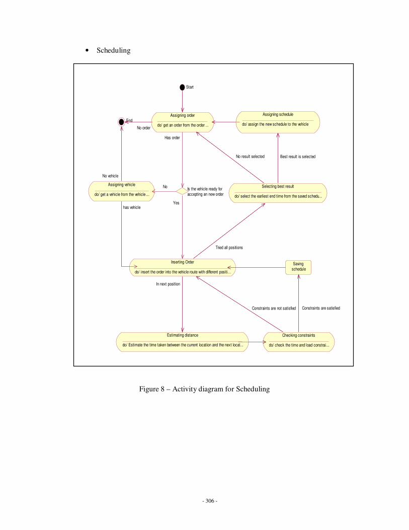
- 306 -
• Scheduling
Figure 8 – Activity diagram for Scheduling
Start
EndAssigning order
do/ get an order from the order list...No order
Assigning vehicle
do/ get a vehicle from the vehicle list...
No vehicle
Inserting Order
do/ insert the order into the vehicle route with different position...
has vehicle
Is the vehicle ready for accepting an new order
Has order
No
Yes
Checking constraints
do/ check the time and load constraints...
Constraints are not satisfied
Selecting best result
do/ select the earliest end time from the saved schedules...
Tried all positions
Estimating distance
do/ Estimate the time taken between the current location and the next location...
In next position
Saving schedule
Constraints are satisfied
Assigning schedule
do/ assign the new schedule to the vehicle
Best result is selectedNo result selected