Embed Size (px)
Citation preview
Managed by UT-Battellefor the Department of Energy
Dynamic Characterization of Spot Welds
Presenter: Phil Sklad*
Principal Investigators: Zhili Feng*, Srdjan Simunovic* and Y.J. (Bill) Chao**
* Oak Ridge National Laboratory** University of South Carolina
February 25-28, 2008
This presentation does not contain any proprietary or confidential information

2
Purpose of Work
•
Key technical development– A workable modeling tool for incorporating the behavior of
spot welds in crash simulations, including strength, failure mode, and deformation rate effects, for better utilization of materials in light-weighting efforts
•
Key objective metrics– A new, robust spot weld element and implementation
procedure that is practical for automotive crash modelers to use
– Companion property database for impact simulation and analysis
– The focus on Advanced High Strength Steels (AHSS) in this program is expandable to other light weight materials and joining technologies in future follow-on activities
3
Supporting Goals of FreedomCAR
•
Efficient optimization of structures for light-weighting while meeting crash requirements requires more accurate models that reflect the special properties of the materials needed for light-weighting.– Near term:
•
Enable more widespread use of advanced high-strength steels in autobody structure to achieve the 20% vehicle weight- reduction for petroleum displacement
– Long term:•
Provide enabling technology for application in Multi-Material Vehicle for even greater vehicle weight-reduction
– Mg-Al, Mg-Steel, etc.– High-volume production– Affordable– Recyclable

4
Barriers•
Industry Consensus (by A/SP Strain Rate Characterization Team)– The prediction of spot weld failure in FEM crash analysis is generally
unsatisfactory, which greatly impedes the overall accuracy of crash analysis of welded structure components
– Spot welds in AHSS are of particular concern because these welds are subject to both ductile (button pullout) and interfacial failure
•
Gap exists in both the fundamental understanding and the practical capability of predicting the failure of spot welded structures in crash
– Why do welds in AHSS and other light-weight materials exhibit different failure modes, and fail more often under impact?
– What are the roles of alloy composition and welding parameters in the change in failure mode?
– What would it take to have crash model adequately handle the deformation and failure of spot welds under impact?
•
Past R&D on AHSS spot welds have been largely under static loading conditions. Experience base for various AHSS under high-strain rate conditions is very limited or nonexistent
5
Implications of Current State of Art
•
We cannot design components containing AHSS and optimize crash performance using numerical analysis with confidence that weld failures will not occur
•
Weld failures detected later, after components are made and tested, frequently result in compromises that adversely affect the 20% weight savings available by using AHSS
•
Further light weighting opportunities from optimized use of AHSS and even higher strength steels will not be fully realized without improved tools for analysis

6
Approach
•
A new spot weld element and associated constitutive models
•
Modeling and characterization of weld microstructure and property
•
Deformation and failure behavior test under dynamic loading conditions
•
Phase I (Dec 2006 - May 2008)– Initial version of the spot weld element
(SWE) and its implementation procedure– Companion experimental data set for
steel grades, thickness, and welding conditions selected by A/SP and OEMs
– SWE Model Demonstration
•
Decision Gate at End of Phase I– Will SWE model work as expected?
•
Phase II (24 months)– Further refinement/improvement of SWE
for other AHSS– Expand to other light-weight materials (Al,
Mg) and welding processes
Program Schedule and GateA Three-Pronged Approach
Input from OEMs & A/SP
Microstructure andproperty characterization
Dynamic and statictesting
Weld process andproperty model
Modeldemonstration
Spot weldelement
3D solid weldcoupon model Failure criteria

7
Dynamic testing: Progress to date (University of South Carolina)
•
Tensile, shear and mixed loading mode tests up to 13 mph impact speed using a special testing apparatus
•
Web-based test data collection and retrieval•
Failure mode and strength correlated to the weld attributes such as weld size and loading rate
0
2000
4000
6000
8000
10000
12000
14000
16000
18000
20000
3.5 4 4.5 5 5.5 6 6.5
Weld Size, mm
DQSK CT DQSK LS
DP780 CT DP780 LS
90%
100%
110%
120%
130%
140%
150%
160%
0 2 4 6 8 10 12 14
Impact speed, mph
DQSK CT d=5.5mm DQSK LP d=4mm
DP780 CT d=5.9mm DP780 LP d=5.1mm
8
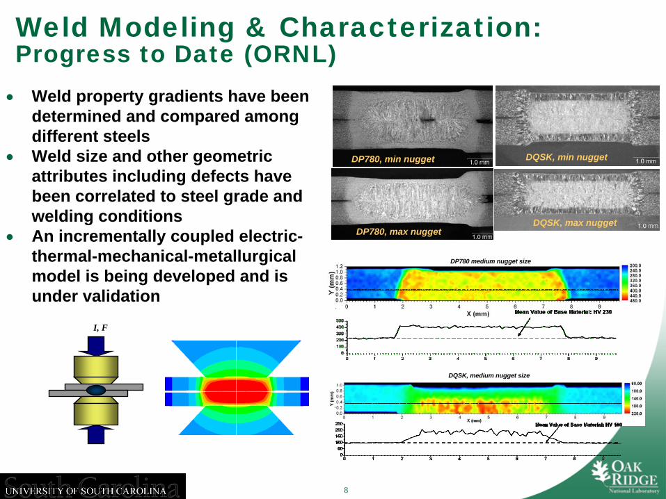
Weld Modeling & Characterization: Progress to Date (ORNL)•
Weld property gradients have been determined and compared among different steels
•
Weld size and other geometric attributes including defects have been correlated to steel grade and welding conditions
•
An incrementally coupled electric- thermal-mechanical-metallurgical model is being developed and is under validation
DP780, min nugget DQSK, min nugget
DP780, max nuggetDQSK, max nugget
DP780 medium nugget size
DQSK, medium nugget size
I, F
9
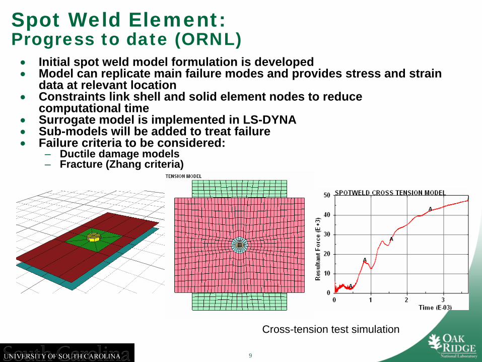
Spot Weld Element: Progress to date (ORNL)
Cross-tension test simulation
•
Initial spot weld model formulation is developed•
Model can replicate main failure modes and provides stress and strain data at relevant location
•
Constraints link shell and solid element nodes to reduce computational time
•
Surrogate model is implemented in LS-DYNA•
Sub-models will be added to treat failure•
Failure criteria to be considered:– Ductile damage models– Fracture (Zhang criteria)
10
Technology Transfer
•
Demonstration of SWE approach is planned at the end of Phase I (May 2008)
•
SWE formulation and implementation will be transferred to industry via A/SP Strain Rate Sensitivity Team (a consortium of the Big- Threes and steel companies)

11
Activities for Next Fiscal Year
•
Complete the development of SWE– Incorporating various failure modes– Verification of SWE with dynamic testing results
•
Phase II– Further refinement and improvement of SWE for
other AHSS materials, thickness combinations– Expand to other lightweight materials (Al and Mg)
and other welding processes

12
Summary
•
The new, robust spot weld crash simulation tool being developed will enable efficient optimization of structures for light-weighting while meeting crash requirement.
•
Dynamic testing, weld characterization and modeling, and initial development of the spot weld element have been completed
•
Activities for the next fiscal year will focus on completion of SWE development, verification, and provide an initial version to the industry
13
Acknowledgement
•
A/SP Strain Rate Characterization Project Team– Kathy Wang (Chair), Dave Mueleman (GM)– Omar Faruque, Tau Tyan (Ford)– J.Z. (Joyce) Cao, Ilaria Accorsi (Chrysler)– Min Kou (ArcelorMittal)– Ming Chen (US Steel)– Raj Mohan (Severstal N.A.)