Embed Size (px)
Citation preview

annals ofUCLEAR ENERGY
Nwww.elsevier.com/locate/anucene
Annals of Nuclear Energy 31 (2004) 1385–1402
Dynamic calculations of the IAEA safetyMTR research reactor Benchmark problem using
RELAP5/3.2 code
Tewfik Hamidouche a, Anis Bousbia-Salah b,*,Martina Adorni b, Franscesco D’Auria b
a Laboratoire des Analyses de Suret�e, Centre de Recherche Nucl�eaire d’Alger (CRNA), 02 Boulevard
Frantz, Fanon, B.P. 399, 16000 Alger, Alg�erieb Dipartimento di Ingegneria Meccanica, Nucleari e della Produzione, Facolt�a di Ingegneria, Universit�a
di Pisa, Via Diotisalvi, 2 – 56126, Pisa, Italy
Received 19 November 2003; accepted 10 March 2004
Available online 23 April 2004
Abstract
Nowadays, increased attention to safety issues for nuclear research reactors has emerged as
a consequence of their enlarged commercial exploitation. Almost all of the research reactors
safety analyses were, so far, performed using conservative computational tools. Currently, the
application of Best-Estimate methods constitutes a real necessity in order to get a more re-
alistic vision of the system behavior, and overcome constraining limits related to conservative
approaches. The aim of the current work is an attempt to apply this technique using the system
thermal-hydraulic RELAP5/Mod3.2 code. For this purpose, the IAEA 10 MW MTR pool
type research reactors Benchmark problem is considered. The exercise consists in performing
some fast transients related to typical reactivity induced accidents, and relatively slow tran-
sients related to loss of flow accidents. The RELAP5 results were compared against previous
data obtained by various conservative channel codes. Differences between the two modeling
approaches are afterwards emphasized and discussed.
� 2004 Elsevier Ltd. All rights reserved.
*Corresponding author.
E-mail addresses: [email protected] (T. Hamidouche), [email protected] (A. Bousbia-
Salah).
0306-4549/$ - see front matter � 2004 Elsevier Ltd. All rights reserved.
doi:10.1016/j.anucene.2004.03.008

1386 T. Hamidouche et al. / Annals of Nuclear Energy 31 (2004) 1385–1402
1. Introduction
Enlarged commercial exploitation of nuclear Research Reactors (RR) has in-
creased the consideration toward their safety issues. RR safety analyses have been,
so far, performed using conservative computational approaches (Woodruff, 1984;
IAEA, 1990; Housiadas, 2000; Hamidouche et al., 2002). However, recent avail-ability of powerful computers and computational techniques together with the
continuing increase in operational experience imposes the revisiting of those areas.
The application of Best-Estimate (BE) method constitutes a real necessity in order to
get more realistically simulations of the phenomena involved during steady state and
transient conditions and eventually the identification of design/safety requirements
that can be relaxed (Bousbia Salah et al., 2003).
The global aim of the current work constitutes an attempt to apply the BE
coupled code approach under the operating conditions of RR. For this purpose, theIAEA 10 MW MTR problem (IAEA, 1980) is considered since it covers a wide
range of hypothetical typical RR transient conditions. The calculations concern
particularly:
• rapid transient initiated by positive Reactivity Induced Accidents (RIA) during an
hypothetic control rod withdrawal, and
• relatively slow transient cases related to Loss Of core coolant Flow Accidents
(LOFA) as a consequence of main cooling pump failure.
In the current framework, only the first step of the coupled code calculationprocedure is considered. In other words, the Thermal-Hydraulic System (THS) code
RELAP5 is used alone taking into account its point Neutron Kinetic (NK) model.
The second step, under progress, will concern three dimensional (3D) calculations
using a 3D NK code.
Unlike the precedent IAEA Benchmark problem calculations based upon channel
code models (IAEA-TECDOC-643, 1990), conservative hypothesis related to the
consideration of imposed core boundary conditions are herein overcome. In fact, a
more realistic simulation is obtained through the consideration of a whole nodal-ization of a typical pool research reactor cooling loop. This will allow, among all, an
adequate simulation of:
• the dynamic interaction between the reactor cooling loop and the core kinetics,
• the flow reversal phenomenon leading to natural circulation regime.
Nevertheless, conservatism related to the consideration of representative core
channels and fixed hot channels peaking factors is kept.
2. IAEA research reactor Benchmark problem
The Benchmark problem consists in some protected transients in MTR Highly
Enriched Uranium (HEU) and Low Enriched Uranium (LEU) cores. These generic
reactors are representative of medium power research reactors with high fissile
loading and more demanding thermal-hydraulic requirements. They are used only to
give an indication of the reliability of the methods adopted. The main Benchmark

Table 1
Main Benchmark problem operating conditions
Core material
Nuclear fuel MTR
Fuel element Plate-type clad in Al
Coolant Light water (downward forced flow)
Moderator Light water
Reflector Graphite-light water
Core thermalhydraulics HEU LEU
Fuel thermal conductivity (W/cmK) 1.58 0.5
Cladding thermal conductivity (W/cmK) 1.80
Radial peaking factor 1.4
Axial peaking factor 1.5
Engineering factor 1.2
Inlet coolant temperature (�C) 38.0
Operating pressure (bar) 1.7
Fuel element dimensions
Length (cm) 8.00
Width (cm) 7.60
Height (cm) 60.0
Number of plates/fuel element ECS/ECN 23 / 17
Plate meat (mm) 0.51
Width (cm) active/ total 6.30/6.65
Height (cm) 60.0
Water channel between plates, mm 2.23
Plate clad thickness (mm) 0.38
Core kinetics HEU LEU
Effective delayed neutron Fraction 7.607E) 3 7.275E) 3
Prompt neutron generation time (ls) 55.96 43.74
Void feedback coefficient ($/% void) 0.3257 0.4047
Doppler feedback coefficient ($/�C) 3.6E) 5 3.31E) 3
Coolant temperature feedback ($/�C) 1.537E) 3 1.082E) 2
T. Hamidouche et al. / Annals of Nuclear Energy 31 (2004) 1385–1402 1387
specifications are outlined in Table 1, and detailed specifications data related to the
kinetics and thermal-hydraulic parameters are given in IAEA (1990). The Bench-
mark problem considers two categories of transients. The rapid one is governed bykinetic processes, whereas the slow category is associated mainly with thermal-
hydraulic phenomena.
2.1. Kinetic (or overpower) transients
This category of transients is characterized by positive reactivity addition into the
core. This leads to core overpower situations where the cooling system, even though
it works under nominal conditions, is not able to evacuate all the heat released intothe core. The leading RIA events are summarized in Table 2. As commonly known,
RIA events are characterized by prompt core power excursion course followed by
strong coupled feedback effects related to Doppler, coolant temperature, and void (if
present) effects. The Fast RIA (FRIA) transients, considered herein, are initiated by
a super prompt ramp positive reactivity addition of $1.5/0.5 s in both HEU and LEU

Table 2
Main Benchmark initial and boundary conditions
Transient key parameters RIA HEU, LEU LOFT HEU, LEU
Initial power 1.0 W 12.0 MW
Steady state duration time before
transient
50 s 50 s
Coolant flow direction Upward (downward in the current
framework)
Downward
Rate of external positive reactivity
addition
($) 1.5/0.5 (Fast RIA) 0.0
($) 1.3/0.5 (Slow RIA-LEU only)
($) 0.09/s (HEU only)
($) 0.10/s (LEU only)
Loss of flow decay period (s) – 1.0 (Fast LOFA)
– 25.0 (Slow LOFA)
Scram setting point 12 MW (120% of nominal power) 85% of nominal core
coolant flow rate
Delay time before Scram 0.025 s 0.2 s
Shut down reactivity )$10.0 in 0.5 s )$10.0 in 0.5 s
1388 T. Hamidouche et al. / Annals of Nuclear Energy 31 (2004) 1385–1402
cores. For the Slow RIA (SRIA), it is considered a positive reactivity insertion of 9
!/s in the HEU core and 10 !/s in the LEU core. The initial conditions are assumed to
be at an operating power of 1 W and full downward cooling flow (not as the
Benchmark specifications which consider initial upward flow). The safety system trip
point is set at 12 MW, it induces the shutdown negative reactivity of )$10 in 0.5 s
with a response delay time of 0.025 s.
2.2. Thermal-hydraulic transients
This category is characterized by a core heat up due to malfunction of the cooling
system even if the reactor power is operating at its nominal value. The transients
related to the LOFA cases involve strong thermal-hydraulic interactions between the
core and the coolant loop. The flow decay is modeled as an exponential ðexpð�t=T ÞÞdecrease with a period T equal to 1 and 25 s for the Fast LOFA (FLOFA) and the
Slow LOFA (SLOFA) cases, respectively. The LOFA transients are initiated at a
nominal core power of 12 MW and full core downward cooling flow conditions. Thereactor scrams when the flow decay is reduced by 15%, with a response delay time of
0.2 s.
Furthermore, when the flow decay reaches 15% of its initial value, the Natural
Convection Valve (NCV) opens to allow flow reversal and the establishment of
passive decay heat removal process by natural circulation flow.
3. Plant nodalization
The IAEA-10 MW HEU and LEU cores consist of 5� 6 grid core containing 21
MTR fuel elements and 4 control elements (see Fig. 1). The core is reflected by
W G G G G G
W ECS5%
ECS25%
ECS25%
ECS5%
W
ECS5%
ECC25%
ECS45%
ECS45%
ECC25%
ECS5%
ECS25%
ECS45%
ECS45%
H2O+
ALECS45%
ECS45%
ECS25%
ECS5%
ECC25%
ECS45%
ECS45%
ECC25%
ECS5%
W ECS5%
ECS25%
ECS25%
ECS25%
W
W G G G G W
Standard Fuel elementECSWater Element W
G ECCGraphite Control fuel element
% % Consumed Uranium
Fig. 1. Benchmark core configuration.
T. Hamidouche et al. / Annals of Nuclear Energy 31 (2004) 1385–1402 1389
graphite on two opposite sides and surrounded by light water. The standard fuel
elements contain 23 plates whereas the control fuel elements contain 17 standard
plates with special region to receive the 4 fork type absorber blades.No information was made available for the reactor cooling loop in the Bench-
mark specification volumes (IAEA, 1980). However, in the current framework, a
standard nodalization performed for a typical MTR research reactor is considered
(Pierro et al., 2003). In fact, an adequate simulation of the interaction between the
reactor cooling loop and the core (dynamic) kinetics as well as flow reversal and
natural circulation phenomena during the LOFA flow decay, needs to take into
account the whole coolant loop components. The adopted plant nodalization for the
Benchmark problem is shown in Fig. 2. It includes the main standard components ofa RR such as the core zone, the reactor pool, the holdup tank, the main coolant
pump, the heat exchanger, and a representative NCV (see also Table 3). The reactor
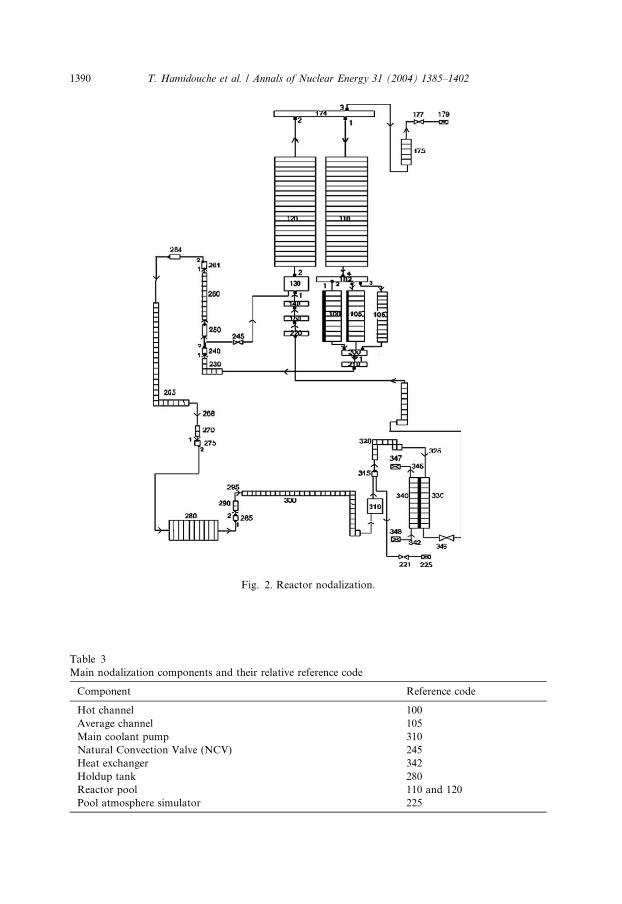
Fig. 2. Reactor nodalization.
Table 3
Main nodalization components and their relative reference code
Component Reference code
Hot channel 100
Average channel 105
Main coolant pump 310
Natural Convection Valve (NCV) 245
Heat exchanger 342
Holdup tank 280
Reactor pool 110 and 120
Pool atmosphere simulator 225
1390 T. Hamidouche et al. / Annals of Nuclear Energy 31 (2004) 1385–1402
T. Hamidouche et al. / Annals of Nuclear Energy 31 (2004) 1385–1402 1391
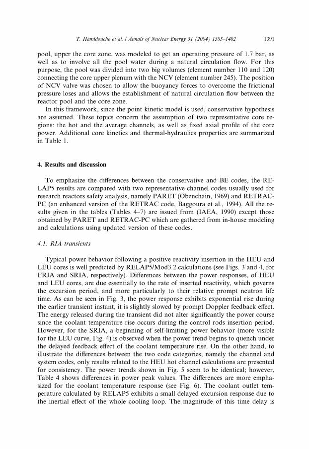
pool, upper the core zone, was modeled to get an operating pressure of 1.7 bar, as
well as to involve all the pool water during a natural circulation flow. For this
purpose, the pool was divided into two big volumes (element number 110 and 120)
connecting the core upper plenum with the NCV (element number 245). The position
of NCV valve was chosen to allow the buoyancy forces to overcome the frictional
pressure loses and allows the establishment of natural circulation flow between thereactor pool and the core zone.
In this framework, since the point kinetic model is used, conservative hypothesis
are assumed. These topics concern the assumption of two representative core re-
gions: the hot and the average channels, as well as fixed axial profile of the core
power. Additional core kinetics and thermal-hydraulics properties are summarized
in Table 1.
4. Results and discussion
To emphasize the differences between the conservative and BE codes, the RE-
LAP5 results are compared with two representative channel codes usually used for
research reactors safety analysis, namely PARET (Obenchain, 1969) and RETRAC-
PC (an enhanced version of the RETRAC code, Baggoura et al., 1994). All the re-
sults given in the tables (Tables 4–7) are issued from (IAEA, 1990) except those
obtained by PARET and RETRAC-PC which are gathered from in-house modelingand calculations using updated version of these codes.
4.1. RIA transients
Typical power behavior following a positive reactivity insertion in the HEU and
LEU cores is well predicted by RELAP5/Mod3.2 calculations (see Figs. 3 and 4, for
FRIA and SRIA, respectively). Differences between the power responses, of HEU
and LEU cores, are due essentially to the rate of inserted reactivity, which governsthe excursion period, and more particularly to their relative prompt neutron life
time. As can be seen in Fig. 3, the power response exhibits exponential rise during
the earlier transient instant, it is slightly slowed by prompt Doppler feedback effect.
The energy released during the transient did not alter significantly the power course
since the coolant temperature rise occurs during the control rods insertion period.
However, for the SRIA, a beginning of self-limiting power behavior (more visible
for the LEU curve, Fig. 4) is observed when the power trend begins to quench under
the delayed feedback effect of the coolant temperature rise. On the other hand, toillustrate the differences between the two code categories, namely the channel and
system codes, only results related to the HEU hot channel calculations are presented
for consistency. The power trends shown in Fig. 5 seem to be identical; however,
Table 4 shows differences in power peak values. The differences are more empha-
sized for the coolant temperature response (see Fig. 6). The coolant outlet tem-
perature calculated by RELAP5 exhibits a small delayed excursion response due to
the inertial effect of the whole cooling loop. The magnitude of this time delay is

Table 4
HEU and LEU – FRIA results
Program name RELAP5/3.2 PARET RETRAC-PC COSTAX-BOIL EUREKA-PT COBRA III-C
Laboratory UPISA ANL LAS JEN JAERI Interatom
Fast reactivity insertion transient $1.5/0.5 s
Minimum period (ms) LEU 12.0 (0.572) 12.13 (0.573) 12.24 (0.572) 13.5 (0.500) 12.2 (0.576) 12 (NA)
HEU 14.70 (0.609) 14.66 (0.609) 14.67 (0.608) 14.5 (0.500) 15.2 (0.619) 14 (0.604)
Peak power (MW) LEU 150.37
(0.612)
148.29
(0.613)
141.14 (0.612) 116.1 (0.638) 143.8 (0.616) 143.9 (0.608)
HEU 131.17
(0.655)
129.01
(0.655)
128.44 (0.655) 132.7 (0.659) 114.8 (0.664) 135.1 (0.650)
Peak clad temperature (�C) LEU 166.55
(0.629)
155.76
(0.629)
155.94 (0.626) 156.6 (0.654) 149.2 (0.627) 168.2 (0.625)
HEU 163.31
(0.673)
155.25
(0.672)
162.04 (0.668) 162.3 (0.675) 147.3 (0.678) 160.0 (0.665)
Onset of nucleate boiling (s) LEU None 0.615–0.668 0.614–0.664 NA NA NA
HEU None 0.656–0.715 0.653–0.719 NA NA NA
Peak coolant temperature (�C) LEU 78.01 (0.728) 82.0 (0.706) 79.42 (0.706) 80.4 (0.711) 62.7 (0.762) 63.2 (0.740)
HEU 78.90 (0.770) 84.32 (0.76) 82.97 (0.745) 108.7 (0.765) 62.3 (0.820) 70.7 (0.783)
Fast reactivity insertion transient $1.35/0.5 s
Minimum period (ms) LEU 17.66 (0.656) 17.52 (0.656) 17.60 (0.655) 19.2 (0.500) 17.1 (0.660) 17 (NA)
Peak power (MW) LEU 64.36 (0.693) 63.16 (0.694) 61.62 (0.693) 51.8 (0.729) 61.5 (0.697) 62.9 (0.688)
Peak clad temperature (�C) LEU 113.23
(0.718)
105.63
(0.718)
107.60 (0.716) 102.1 (0.756) 107.2 (0.722) 105.1 (0.710)
Peak coolant temperature LEU 56.18 (0.826) 57.86 (0.815) 56.84 (0.804) 54.9 (0.840) 55.2 (0.827) 52.0 (0.840)
Quantities between parentheses indicate time in seconds at which values occur.
NA: data not available in TECDOC-643.
UPISA: University of PISA (Italy); ANL: Argonne National Laboratory (USA); LAS: Laboratoire d’Analyse de Suret�e (Algeria); JEN: Junta de Energia
Nuclear (Spain); JAERI: Japan Atomic Energy Research Institute (Japan); INTERATOM: (Germany).
1392
T.Hamidoucheet
al./AnnalsofNuclea
rEnerg
y31(2004)1385–1402

Table 5
HEU and LEU – SRIA results
Program name RELAP5/3.2 PARET RETRAC-PC COSTAX-BOIL EUREKA-PT COBRA III-C
Laboratory UPISA ANL LAS JEN JAERI Interatom
Slow reactivity insertion 0.10$/s – HEU core
Minimum period (s) HEU 0.099 (10.62) 0.152 (10.62) 0.148 (10.62) 0.145 (10.61) NA 0.10
Peak power (MW) HEU 13.69 (10.65) 13.74 (10.65) 14.05 (10.64) 14.05 (10.64) 13.75 (10.668) 14.36 (10.59)
Peak clad temperature (�C) HEU 71.70 (10.66) 69.30 (10.67) 75.01 (10.66) 75.01 (10.66) 69.2 (10.693) 69.2 (10.62)
Peak coolant temperature (�C) HEU 47.98 (10.74) 48.21 (10.73) 48.05 (10.37) 48.05 (10.73) 47.7 (10.773) 45.2 (10.70)
Power (MW) at 20 s HEU 0.0078 0.0055 0.0049 0.0049 0.006 NA
Clad temperature (�C) at 20 s HEU 38.0 38.02 38.01 38.01 NA NA
Coolant temperature (�C) at 20 s HEU 38.0 38.00 38.00 38.00 NA NA
Slow reactivity insertion 0.09$/s – LEU core
Minimum period (s) LEU 0.088 (11.92) 0.85 (11.87) 1.10 (11.80) 1.11 (11.80) NA 0.11
Peak power (MW) LEU 12.34 (11.94) 12.36 (11.9) 12.29 (11.82) 12.29 (11.82) 12.35 (11.923) 12.18 (12.053)
Peak clad temperature (�C) LEU 81.12 (11.95) 77.59 (11.91) 78.52 (11.83) 78.52 (11.83) 78.5 (11.933) 78.1 (12.06)
Peak coolant temperature (�C) LEU 53.15 (11.99) 53.73 (11.94) 53.52 (11.83) 53.52 (11.88) 52.8 (11.978) 51.1 (12.10)
Power (MW) at 20 s LEU 0.022 0.0147 0.128 0.0128 0.015 NA
Clad temperature (�C) at 20 s LEU 38.0 38.06 38.04 38.04 NA NA
Coolant temperature (�C) at 20 s LEU 38.0 38.02 38.00 38.00 NA NA
Quantities between parentheses indicate time in seconds at which values occur.
NA: data not available in TECDOC-643.
UPISA: University of PISA (Italy); ANL: Argonne National Laboratory (USA); LAS: Laboratoire d’Analyse de Suret�e (Algeria); JEN: Junta de Energia
Nuclear (Spain); JAERI: Japan Atomic Energy Research Institute (Japan); INTERATOM: (Germany).
T.Hamidoucheet
al./AnnalsofNuclea
rEnerg
y31(2004)1385–1402
1393

0.0 0.2 0.4 0.6 0.8 1.0 1.2 1.4 1.6 1.8 2 .0
Time (sec)
1.0E+0
1.0E+1
1.0E+2
1.0E+3
1.0E+4
1.0E+5
1.0E+6
1.0E+7
1.0E+8
1.0E+9
Po
wer
(W
atts
)
RIA TRANSIENTS
LEU - $1.35 / 0.5sec
HEU - $ 1.5 /0.5 sec
LEU - $ 1.5 / 0.5 sec
Fig. 3. Core power evolutions during RIA transients.
0.0 4.0 8.0 12.0 16.0 20.0
Time (sec)
1.0E+0
1.0E+1
1.0E+2
1.0E+3
1.0E+4
1.0E+5
1.0E+6
1.0E+7
1.0E+8
Pow
er (W
atts
)
SRIA TRANSIENTS
HEU - $ 0.1 /sec
LEU - $ 0.09 / sec
Fig. 4. Core power evolutions during SRIA transients.
1394 T. Hamidouche et al. / Annals of Nuclear Energy 31 (2004) 1385–1402
proportional to the ratio of the length of the pipe versus its flow area (i.e. L=A)(Lewis, 1979). This effect is not observed in the channel codes calculations and, as
shown in Fig. 6 a prompt coolant temperature response is predicted. Furthermore,

0.0 0.3 0.5 0.8 1.0
Time (sec)
1.0E-1
1.0E+0
1.0E+1
1.0E+2
1.0E+3
1.0E+4
1.0E+5
1.0E+6
1.0E+7
1.0E+8
1.0E+9
Po
wer
(W
atts
)
-6.0
-4.5
-3.0
-1.5
0.0
1.5
3.0
Rea
ctiv
ity (D
olla
rs)
RELAP5
PARET
RETRAC
Scram
Fig. 5. Power and compensated reactivity during HEU-FRIA transient.
0.0 0.2 0.4 0.6 0.8 1.0
Time (sec)
20.0
40.0
60.0
80.0
100.0
Tem
pera
ture
( C
)
HEU $1.5/0.5 sec
RELAP5
PARET
RETRAC
Time of Peak power
Fig. 6. Coolant outlet temperature during HEU-FRIA transient.
T. Hamidouche et al. / Annals of Nuclear Energy 31 (2004) 1385–1402 1395
while channel codes assume fixed core inlet flow, the RELAP5 calculation predicts a
dynamic variation of this parameter (see Fig. 7). The core flow rate exhibits a pulse
reduction during the power excursion phase due to interactions between the core
and the coolant loop.

0.0 0.2 0.4 0.6 0.8 1.0 1.2 1.4 1.6 1.8 2.0
Time (sec)
-138.0
-137.0
-136.0
-135.0
-134.0
-133.0
-132.0
-131.0
-130.0
Mas
s Fl
ow (k
g/se
c/m
2)
HEU $1.5/0.5 sec
Core outlet Flow
core inlet Flow
Time of Trip
Fig. 7. Inlet and outlet core flow during HEU-FRIA transient.
0.0 0.2 0.4 0.6 0.8 1.0
Time (sec)
0.0
40.0
80.0
120.0
160.0
200.0
Tem
pera
ture
( C
)
HEU $1.5/0.5 sec
RELAP5
PARET
RETRAC
Fig. 8. Clad surface temperature during HEU-FRIA transient.
1396 T. Hamidouche et al. / Annals of Nuclear Energy 31 (2004) 1385–1402

T. Hamidouche et al. / Annals of Nuclear Energy 31 (2004) 1385–1402 1397
In fact, as can be seen in Fig. 2, some part of the recirculation loop are above the
core level (element number 260), and if an overheat of the core takes place, the fluid
circulation tends to turn back under the effect buoyancy forces (differences in static
head between the cold water in the piping and the hot water in the core). The role of
these buoyancy forces is more pronounced in the case of LOFA transients.
Conversely, it should be noted that PARET and RETRAC-PC predict the Onsetof subcooled Nucleate Boiling (ONB) regime for a short time just before the peak
power time occurrence (see Table 4). This two-phase flow regime takes place when
the cladding temperature is higher than the ONB temperature ðTONBclad � 126 �C).
However, no boiling is predicted by the RELAP5/Mod 3.2 code even though higher
cladding temperature is obtained (up to 160 �C) (see Fig. 8 and Table 4). Similar
result was obtained by another RELAP5/Mod3 version (Woodruff et al., 1996), even
though no nodalization for an external loop was made. This may be due, as outlined
by (Kon�ear and Mavko, 2003), to inadequate RELAP5 Lahey’s model in predictingthe ONB under low pressure operating conditions. The higher predicted peak power
by RELAP5 (see Table 4) could be explained by the absence of void feedback
contribution during the power excursion course.
For the SRIA, as outlined in Table 5, differences between REALP5 and channel
codes results are practically insignificant for both power and temperature responses.
In fact, the core and the coolant loop interactions are weak since the dynamic of the
transient is very slow in this case.
4.2. LOFA transients
At a certain moment of the LOFA course, the buoyancy forces, due to the coolant
heat up by the decay heat generation, become important in comparison with the
decaying pump active forces. A mixed convection flow establishes followed by a flow
reversal and natural circulation regime. As pointed out by the TECDOC-643
Benchmark specifications (volume 1), the LOFA calculations are ended when the flow
decay reaches 15% of its nominal value. This limitation is mainly due to the inade-quacy of almost of the used channel computational tools, reported in Tables 6 and 7,
in performing further calculations involving thermal-hydraulic interactions between
the core and its cooling loop. However, the use of RELAP5 code allows the simu-
lation of all the leading processes to the natural convection regime. In the current
framework, only some representative LOFA results for HEU core are displayed.
The main output parameters of the transients, calculated by RELAP5/Mod3.2
code, are summarized in Table 6 for FLOFA and Table 7 for SLOFA in comparison
with the results of some channel codes as reported in (IAEA-TECDOC 643).Practically, no differences are observed between the HEU and LEU power responses.
This expected behavior is due to weak kinetic feedback effects involved during such
transients. On the other hand, the temperature responses are reported in Figs. 9 and
10. The fuel and the coolant temperatures exhibit a steady rise due to the degra-
dation of the core cooling process during the flow decay. After the scram of the
reactor power, a sharp decrease of core temperature is observed. However, due to the
combined effect of constant decay heat and continuous reduction of the core flow

Table 6
HEU and LEU – FLOFA results
Program name RELAP5/3.2 PARET RETRAC-PC COSTAX-BOIL EUREKA-PT COBRA III-C
Laboratory UPISA ANL LAS JEN JAERI INTERATOM
Power core at scram
(85% of nominal flow)
(MW)
LEU 11.83 (0.190) 11.86 (0.295) 11.72 (0.185) 11.67 NA 11.4 (0.363)
HEU 11.87 (0.200) 11.85 (0.295) 11.75 (0.192) 1167 NA 11.5 (0.363)
1st Peak cladding
temperature (�C)LEU 92.58 (0.400) 89.46 (0.505) 87.92 (0.400) 93.9 (0.37) 97.1 (0.40) 89.3 (0.363)
HEU 91.28 (0.408) 89.43 (0.505) 91.74 (0.385) 94.0 (0.37) 98.4 (0.40) 89.5 (0.380)
1st Peak coolant
temperature (�C)LEU 59.50 (0.504) 60.84 (0.601) 59.92 (0.465) 59.3 (0.43) 58.1 (0.48) 56.4 (0.460)
HEU 59.53 (0.503) 60.94(0.602) 60.04 (0.481) 59.4 (0.43) 58.4(0.48) 56.5 (0.460)
Flow inversion time (s) LEU 7.40 4.415 7.36a NA NA NA
HEU 7.40 4.415 7.66a NA NA NA
Coolant temperature
at 15% of nominal flow
LEU 46.70 47.15 45.63 NA NA NA
HEU 46.79 47.16 45.21 NA NA NA
2nd Peak cladding
temperature (�C)LEU 120.73 (10.00) 105.90 (8.51) 128.25 (7.36)a NA 95.2 (10.0) NA
HEU 121.00 (10.20) 105.76 (8.91) 112.12 (7.36)a NA 106.0 (10.0) NA
2nd Peak cooling
temperature (�C)LEU 105.3 (11.90) 101.67 (9.14) 69.76a NA 49.3 (10.0) NA
HEU 107.06 (11.10) 101.68 (9.13) 54.37a NA 48.3 (10.0) NA
Quantities between parentheses indicate time in seconds at which values occur.
NA: data not available in TECDOC-643.
UPISA: University of PISA (Italy); ANL: Argonne National Laboratory (USA); LAS: Laboratoire d’Analyse de Suret�e (Algeria); JEN: Junta de Energia
Nuclear (Spain); JAERI: Japan Atomic Energy Research Institute (Japan); INTERATOM: (Germany).aData given when RETRAC-PC calculations stopped (no flow inversion).
1398
T.Hamidoucheet
al./AnnalsofNuclea
rEnerg
y31(2004)1385–1402

Table 7
HEU and LEU – LOFA results
Program name RELAP5/3.2 PARET RETRAC-PC COSTAX-BOIL EUREKA-PT COBRA III-C
Laboratory UPISA ANL LAS JEN JAERI Interatom
Power core at scram (MW) LEU 11.56 (4.102) 11.64 (3.87) 11.56 (4.050) 11.7 (4.06) NA 11.46 (4.263)
HEU 11.62 (4.098) 11.62 (3.915) 11.61 (4.047) 11.8 (4.06) NA 11.55 (4.263)
1st Peak cladding
temperature (�C)LEU 88.41 (4.299) 84.56 (4.07) 84.63 4.240) 90.3 (4.27) 96.1 (4.20) 85.5 (4.263)
HEU 88.67 (4.305) 84.51 (4.07) 84.69 (4.160) 90.7 (4.27) 96.4 (4.20) 85.8 (4.263)
1st Coolant peak
temperature (�C)LEU 57.97 (4.300) 58.83 (4.075) 58.82 (4.272) 58.1 (4.27) 57.5 (4.30) 55.4 (4.263)
HEU 58.78 (4.305) 58.81 (4.075) 58.83 (4.16) 58.3 (4.27) 57.7 (4.30) 55.6 (4.263)
Clad temperature at
15% of flow (�C)LEU 49.38 (47.50) 48.61 (43.58) 49.21 (47.19) NA 41.1 (10.0) NA
HEU 49.34 (47.39) 48.61 (43.57) 49.56 (43.83) NA 41.1 (10.0) NA
Cool. temperature at
15 % of flow (�C)LEU 43.50 43.43 42.42 NA 39.0 (10.0) NA
HEU 43.47 43.42 42.48 NA 39.0 (10.0) NA
Flow inversion time (s) LEU 57.40 62.84 57.26a NA NA
HEU 57.40 61.82 57.26a NA NA
2nd Clad peak
temperature (�C)LEU 98.48 (61.58) 98.23 (70.74) 79.29 (57.26)a 43.9 (45.0) NA NA
HEU 98.48 (61.58) 98.23 (70.74) 77.87 (57.26)a 43.9 (45.0) NA NA
2nd Coolant peak
temperature (�C)LEU 87.36 (64.20) 94.21 (70.74) 58.77 (57.26)a 44.0 (45.0) NA NA
HEU 87.11 (64.19) 98.23 (70.74) 65.20 (57.26)a 43.9 (45.0) NA NA
Quantities between parentheses indicate time in seconds at which values occur.
NA: data not available in TECDOC-643.
UPISA: University of PISA (Italy); ANL: Argonne National Laboratory (USA); LAS: Laboratoire d’Analyse de Suret�e (Algeria); JEN: Junta de Energia
Nuclear (Spain); JAERI: Japan Atomic Energy Research Institute (Japan); INTERATOM: (Germany).aData given when RETRAC-PC calculations stopped (no flow inversion).
T.Hamidoucheet
al./AnnalsofNuclea
rEnerg
y31(2004)1385–1402
1399

0.00 4.00 8.00 12.00 16.00 20.00
Time (Sec)
20.00
40.00
60.00
80.00
100.00
120.00
140.00
Tem
per
atu
re (
C)
HEU FLOFA
RELAP
PARET
RETRAC
-1.0
0.0
1.0
2.0
3.0
Rel
ativ
e In
let M
ass
Flow
Flow Inversion
Fig. 9. Clad surface temperature and relative inlet mass flow rate during HEU-FLOFA transient.
0.00 20.00 40.00 60.00 80.00 100.00
Time (Sec)
0.00
20.00
40.00
60.00
80.00
100.00
120.00
Tem
per
atu
re (
C)
HEU SLOFA
RELAP5
PARET
RETRAC
-1.0
0.0
1.0
2.0
Rel
ativ
e In
let M
ass
Flow
Flow Inversion
Fig. 10. Clad surface temperature and relative inlet mass flow rate during HEU-SLOFA transient.
1400 T. Hamidouche et al. / Annals of Nuclear Energy 31 (2004) 1385–1402
rate, the core temperatures exhibit a second rise. The increase is further sustained as
the flow regime passes to laminar regime and to mixed flow when the NCV opens.
The core temperatures begin to decrease only when the natural circulation flow is
fully established. In Figs. 9 and 10 are also displayed the temperature responses and
the flow evolutions as calculated by PARET and RETRAC-PC codes. As it is ex-
pected, differences appear during the flow inversion phase. Indeed, this phenomenon
is governed by the balance between the system inertia ðL=AÞ and the buoyancy forces

T. Hamidouche et al. / Annals of Nuclear Energy 31 (2004) 1385–1402 1401
involved during the flow decay process. In comparison with PARET results, RE-
LAP5 predicts delayed flow inversion for FLOFA while in SLOFA cases the flow
inversion occurs earlier. This could be explained by the fact that unlike PARET
calculations, RELAP5 model take into account two key transient parameters; the
coolant loop inertia and more realistic buoyancy forces effects. For FLOFA, the
delayed response predicted by RELAP5 is due to the system inertia effect which isnot considered by PARET calculations. Whereas for slow transients, the flow in-
version is mainly governed by differences in modeling the buoyancy forces effect.
In general, differences between the RELAP5 and channel codes predictions for the
LOFA transients are mainly related to the thermal-hydraulic interactions between
the core and the coolant loop. These mechanisms could not, in any case, be ade-
quately simulated without considering the effect of different components of the real
plant configuration.
5. Conclusions
Increased consideration to safety issues for research reactors exploitation has
emerged as a consequence of their enlarged commercial exploitation. So far,
conservative computational tools were used to perform safety analyses for the design
and exploitation of such reactors. Nowadays it becomes necessary to review such
limiting tools by using Best-Estimate calculation methods. The current work consti-tutes a first attempt to apply this technique to the Research Reactors operating con-
ditions. For these purpose the well-known IAEA Research Reactors Benchmark
problem is considered. In general, for all the considered transients, the obtained results
show similar trendswith some specified channel codes results.However, as emphasized
by the comparative study, the RELAP5 simulation seems to be more realistic since it
take into account the interaction between the coolant loop and the core dynamic,
especially, during fast power excursion and loss of flow transients. Nevertheless, it
seems that low pressure models embedded into the current RELAP5/3.2 version arenot capable to predict correctly the onset of subcooled nucleate boiling flow regime.
A further investigation of the current Benchmark problem will be performed by
taking into account a more realistic neutron kinetic response using coupled THS-3D-
NK code simulations.
Acknowledgements
This work was performed under the auspices of Nuclear Research Center of
Algiers, in cooperation with the International Atomic Energy Agency (IAEA)through a contract Research Project (RP-ALG-12299).
References
Baggoura, B., Hamidouche, T., Bousbia Salah, A., 1994. RETRAC: a computer code for the analysis of
materials test reactors. Nuclear Science and Engineering 118.

1402 T. Hamidouche et al. / Annals of Nuclear Energy 31 (2004) 1385–1402
Bousbia Salah, A., Lo Nigro, A., D’Auria, F., Galassi, G.M., Giannotti, W., 2003. Overview of coupled
3D system thermalhydraulics neutron kinetics code applications. In: IAEA Technical Meeting on
Progress in Development and Use of Coupled Codes for Accident Analysis, Vienna.
Hamidouche, T., Bousbia-salah, A., Mazrou, H., Ibrahim K., 2002. RETRAC-PC: A computer program
for the analysis of transients in nuclear research reactor cores. In: International Conference on the New
Frontiers of Nuclear Technology: Reactor Physics, Safety and High-Performance Computing,
PHYSOR 2002, Seoul.
Housiadas, C., 2000. Simulation of loss of flow transients in research reactors. Annals of Nuclear Energy
27, 1683–1693.
IAEA, 1990. Research Reactor Core Conversion Guidebook, Volume-3: Analytical Verification. IAEA-
TECDOC-643.
IAEA, 1980. Research Reactor Core Conversion from the use of high enriched uranium to the use of low
enriched uranium fuels Guidebook. IAEA-TECDOC-233.
Kon�ear, B., Mavko, B., 2003. Modeling of low-pressure subcooled flow boiling using the RELAP5 code.
Nuclear Engineering and Design 220, 255–273.
Lewis, E.E., 1979. Nuclear Power Reactor Safety. Wiley, New York.
Obenchain, C.F., 1969. PARET – A Program for the Analysis of Reactor Transients. IDO-17282.
Pierro, F., Di Maro, B., Bousbia Salah, A., Adorni, M., D’Auria, F., 2003. Safety analysis of loss of flow
transients in a Typical Research Reactor by RELAP5/Mod3.3. Nuclear Energy for New Europe,
Portoroz, Slovenia.
Woodruff, W.L., 1984. A kinetic and thermal-hydraulic capability for the analysis of research reactors.
Nuclear Technology 64.
Woodruff, W.L., Hanan, N.A., Smith, R.S., Matos, J.E., 1996. A comparison of the PARET/ANL and
RELAP5/Mod3.3 codes for the analysis of IAEA Benchmark transients. In: International Meeting on
Reduced Enrichment for Research and Test Reactors, October 7–10, Seoul, South Korea.


![Motor unit MTR-DCI€¦ · Description MTR-DCI-...IO Description 539616 en 1209d [763197] Motor unit MTR-DCI](https://img.pdfslide.us/doc/110x75/5f50cafd0ff31e4afa1c4f9b/motor-unit-mtr-dci-description-mtr-dci-io-description-539616-en-1209d-763197.jpg)