Embed Size (px)
Citation preview
Dynamic Automatic Triaxial
Test System
The System
How it Works
Software
Unsaturated

The SYSTEM
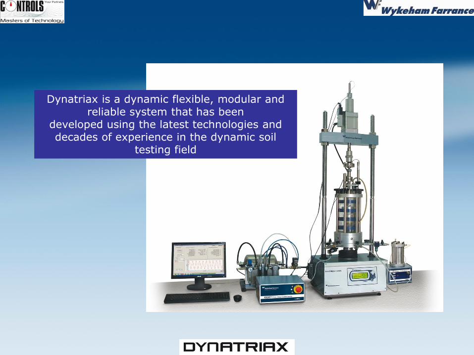
Dynatriax is a dynamic flexible, modular and reliable system that has been
developed using the latest technologies and decades of experience in the dynamic soil
testing field
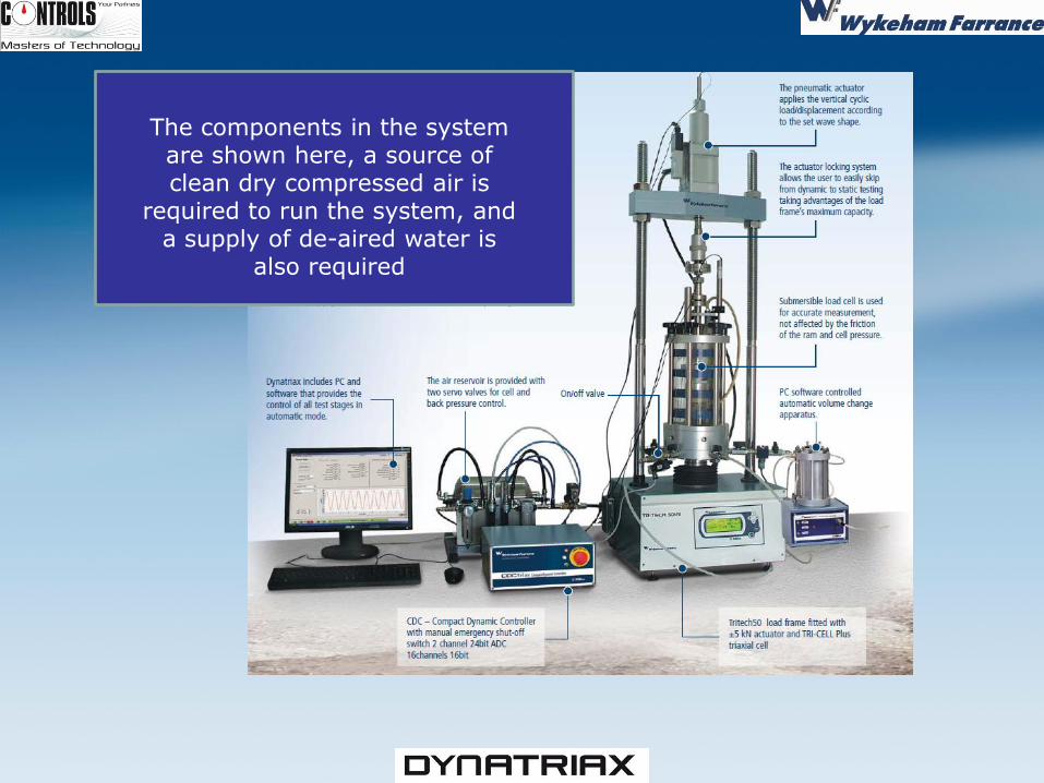
The components in the system are shown here, a source of clean dry compressed air is
required to run the system, and a supply of de-aired water is
also required
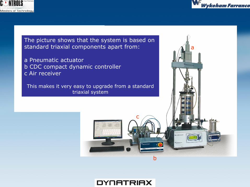
The picture shows that the system is based on standard triaxial components apart from: a Pneumatic actuator b CDC compact dynamic controller c Air receiver This makes it very easy to upgrade from a standard
triaxial system
a
b
c
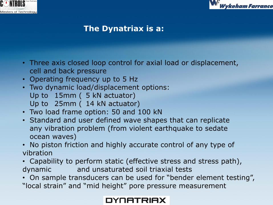
The Dynatriax is a: • Three axis closed loop control for axial load or displacement, cell and back pressure • Operating frequency up to 5 Hz • Two dynamic load/displacement options: Up to 15mm ( 5 kN actuator) Up to 25mm ( 14 kN actuator)
• Two load frame option: 50 and 100 kN • Standard and user defined wave shapes that can replicate any vibration problem (from violent earthquake to sedate ocean waves) • No piston friction and highly accurate control of any type of vibration • Capability to perform static (effective stress and stress path), dynamic and unsaturated soil triaxial tests • On sample transducers can be used for “bender element testing”, “local strain” and “mid height” pore pressure measurement
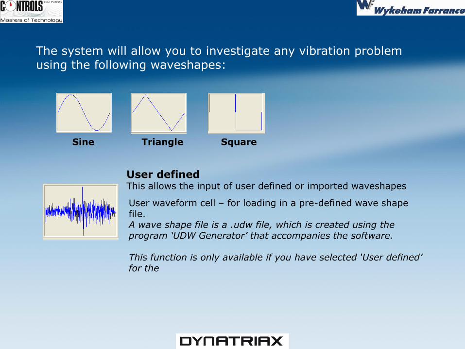
The system will allow you to investigate any vibration problem using the following waveshapes:
Sine Triangle Square
User defined This allows the input of user defined or imported waveshapes
User waveform cell – for loading in a pre-defined wave shape file. A wave shape file is a .udw file, which is created using the program ‘UDW Generator’ that accompanies the software. This function is only available if you have selected ‘User defined’ for the
9
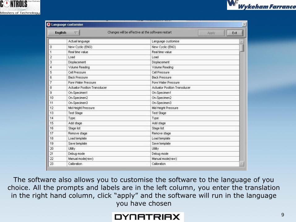
The software also allows you to customise the software to the language of you choice. All the prompts and labels are in the left column, you enter the translation in the right hand column, click “apply” and the software will run in the language
you have chosen
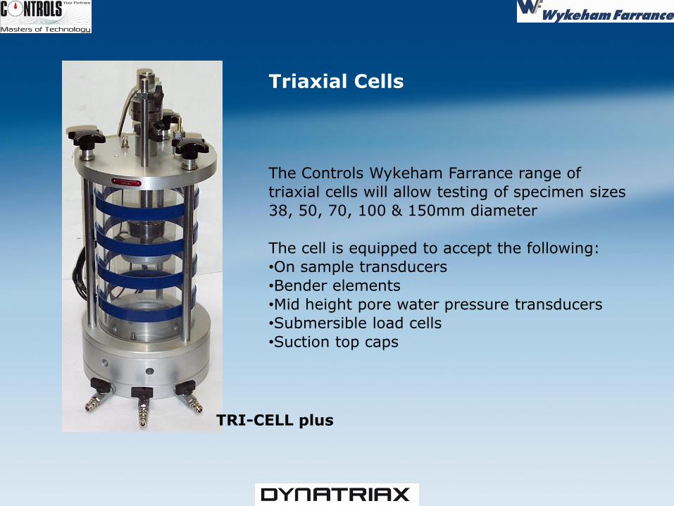
TRI-CELL plus
The Controls Wykeham Farrance range of
triaxial cells will allow testing of specimen sizes
38, 50, 70, 100 & 150mm diameter
The cell is equipped to accept the following:
•On sample transducers
•Bender elements
•Mid height pore water pressure transducers
•Submersible load cells
•Suction top caps
Triaxial Cells
HOW IT
WORKS
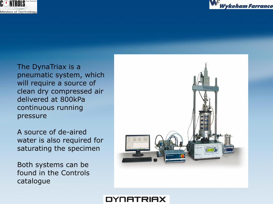
The DynaTriax is a pneumatic system, which will require a source of clean dry compressed air delivered at 800kPa continuous running pressure A source of de-aired water is also required for saturating the specimen Both systems can be found in the Controls catalogue
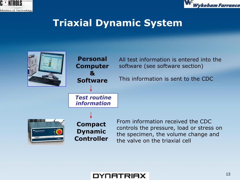
Personal Computer
& Software
Triaxial Dynamic System
Test routine information
Compact Dynamic
Controller
13
All test information is entered into the software (see software section) This information is sent to the CDC
From information received the CDC controls the pressure, load or stress on the specimen, the volume change and the valve on the triaxial cell
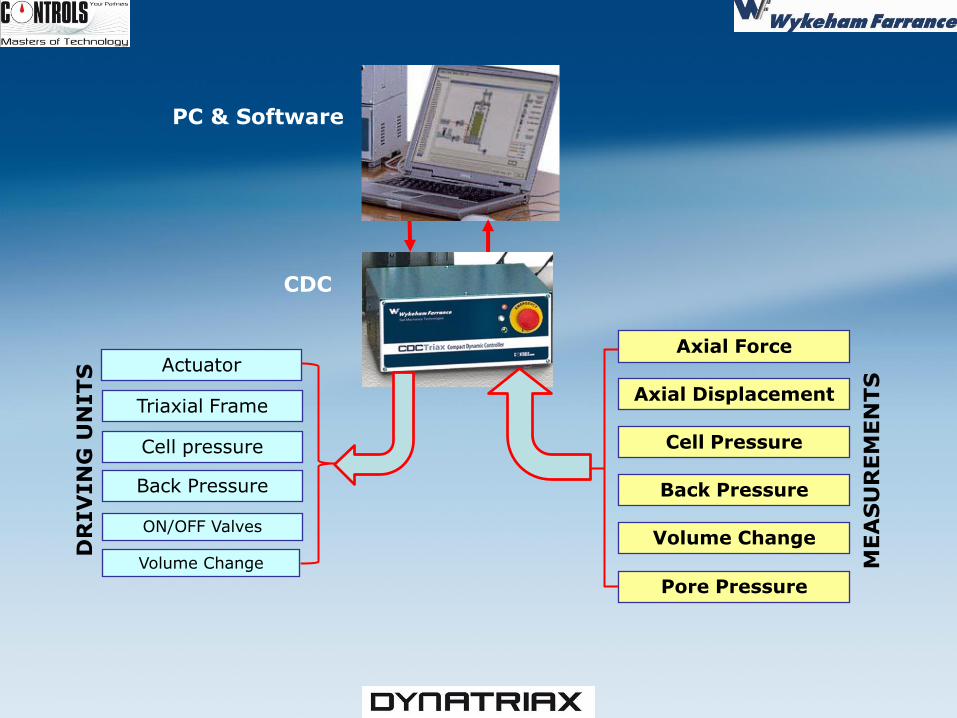
PC & Software
CDC
Volume Change
Pore Pressure
Back Pressure
Cell Pressure
Axial Displacement
Axial Force
MEA
SU
REM
EN
TS
Back Pressure
Cell pressure
Triaxial Frame
Volume Change
ON/OFF Valves
DR
IV
IN
G U
NITS
Actuator
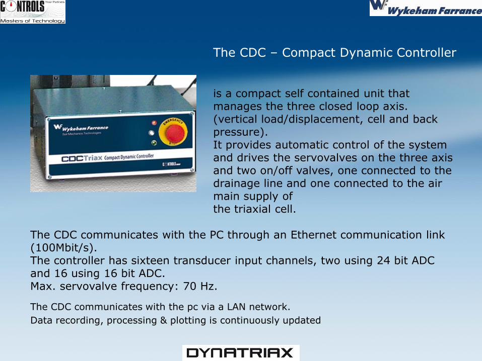
The CDC communicates with the pc via a LAN network.
Data recording, processing & plotting is continuously updated
The CDC – Compact Dynamic Controller is a compact self contained unit that manages the three closed loop axis. (vertical load/displacement, cell and back pressure). It provides automatic control of the system and drives the servovalves on the three axis and two on/off valves, one connected to the drainage line and one connected to the air main supply of the triaxial cell.
The CDC communicates with the PC through an Ethernet communication link (100Mbit/s). The controller has sixteen transducer input channels, two using 24 bit ADC and 16 using 16 bit ADC. Max. servovalve frequency: 70 Hz.
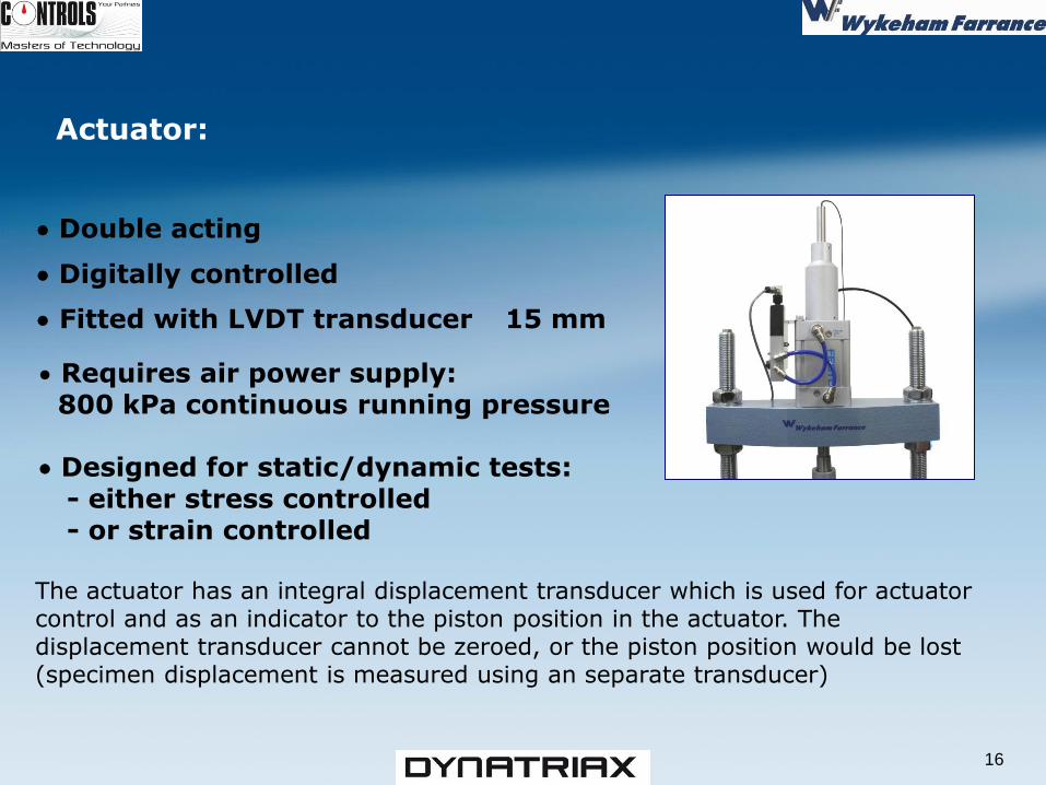
Actuator: Double acting
Digitally controlled
Fitted with LVDT transducer 15 mm
16
Requires air power supply: 800 kPa continuous running pressure Designed for static/dynamic tests: - either stress controlled - or strain controlled
The actuator has an integral displacement transducer which is used for actuator control and as an indicator to the piston position in the actuator. The displacement transducer cannot be zeroed, or the piston position would be lost (specimen displacement is measured using an separate transducer)
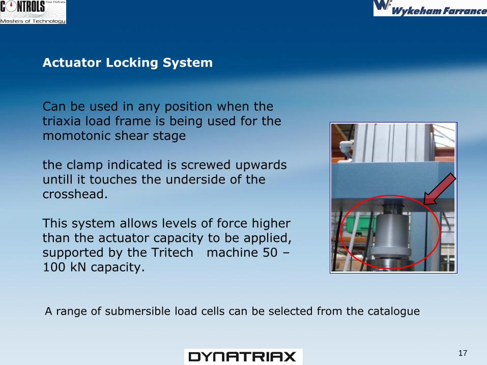
Actuator Locking System Can be used in any position when the triaxia load frame is being used for the momotonic shear stage the clamp indicated is screwed upwards untill it touches the underside of the crosshead. This system allows levels of force higher than the actuator capacity to be applied, supported by the Tritech machine 50 – 100 kN capacity.
17
A range of submersible load cells can be selected from the catalogue
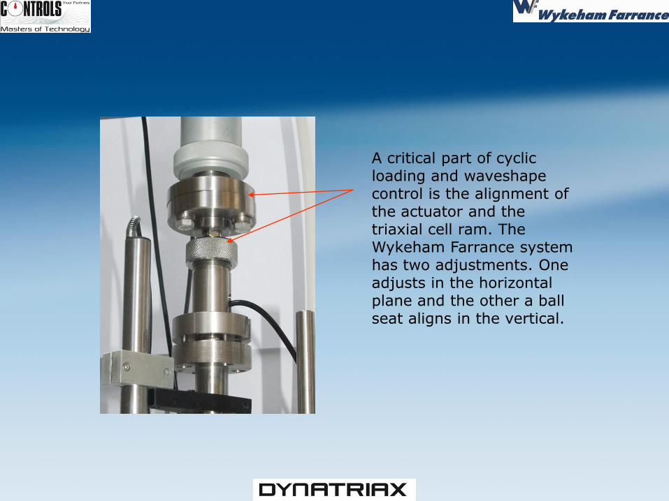
A critical part of cyclic loading and waveshape control is the alignment of the actuator and the triaxial cell ram. The Wykeham Farrance system has two adjustments. One adjusts in the horizontal plane and the other a ball seat aligns in the vertical.
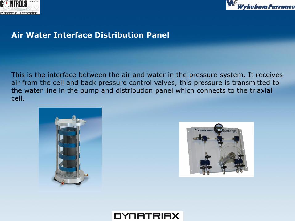
Air Water Interface Distribution Panel This is the interface between the air and water in the pressure system. It receives air from the cell and back pressure control valves, this pressure is transmitted to the water line in the pump and distribution panel which connects to the triaxial cell.
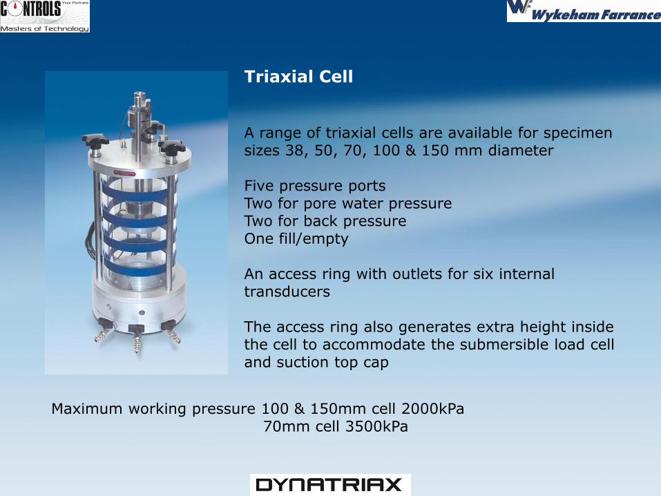
Triaxial Cell A range of triaxial cells are available for specimen sizes 38, 50, 70, 100 & 150 mm diameter Five pressure ports Two for pore water pressure Two for back pressure One fill/empty An access ring with outlets for six internal transducers The access ring also generates extra height inside the cell to accommodate the submersible load cell and suction top cap
Maximum working pressure 100 & 150mm cell 2000kPa 70mm cell 3500kPa
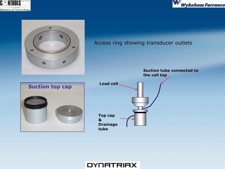
Access ring showing transducer outlets
Suction top cap Load cell
Suction tube connected to the cell top
Top cap & Drainage tube
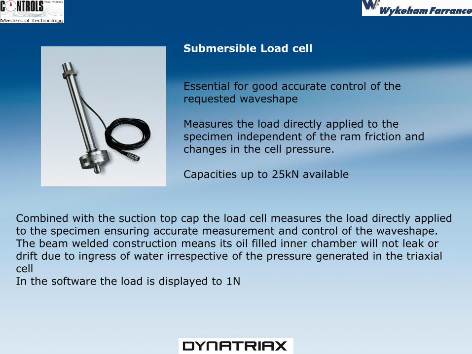
Submersible Load cell Essential for good accurate control of the requested waveshape Measures the load directly applied to the specimen independent of the ram friction and changes in the cell pressure. Capacities up to 25kN available
Combined with the suction top cap the load cell measures the load directly applied to the specimen ensuring accurate measurement and control of the waveshape. The beam welded construction means its oil filled inner chamber will not leak or drift due to ingress of water irrespective of the pressure generated in the triaxial cell In the software the load is displayed to 1N
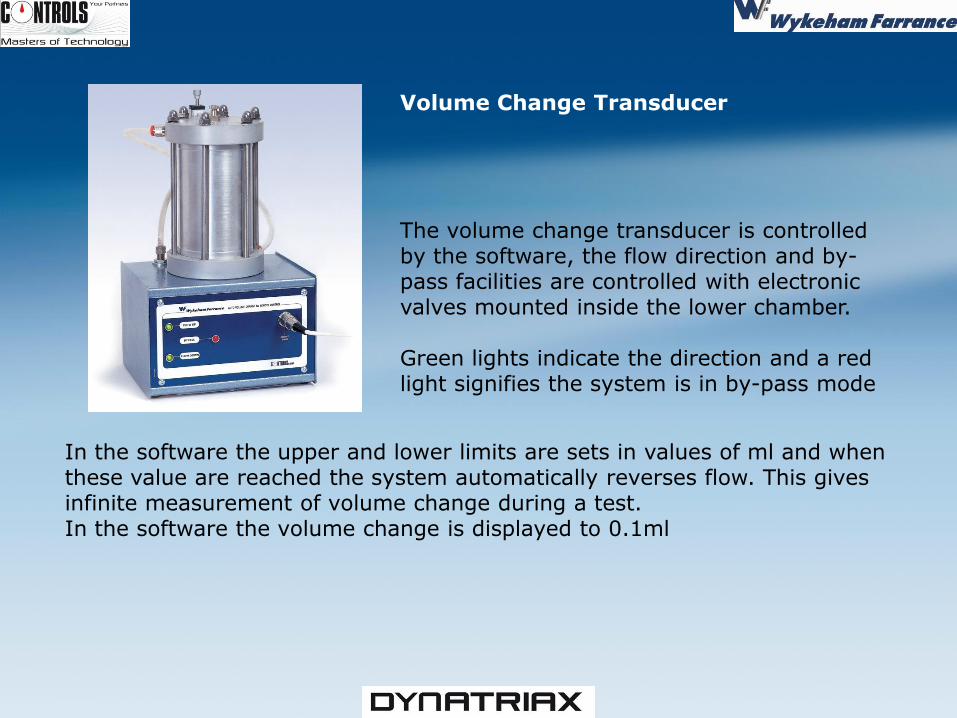
Volume Change Transducer The volume change transducer is controlled by the software, the flow direction and by-pass facilities are controlled with electronic valves mounted inside the lower chamber. Green lights indicate the direction and a red light signifies the system is in by-pass mode
In the software the upper and lower limits are sets in values of ml and when these value are reached the system automatically reverses flow. This gives infinite measurement of volume change during a test. In the software the volume change is displayed to 0.1ml
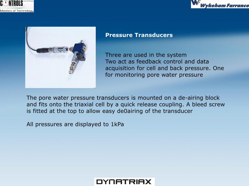
Pressure Transducers Three are used in the system Two act as feedback control and data acquisition for cell and back pressure. One for monitoring pore water pressure
The pore water pressure transducers is mounted on a de-airing block and fits onto the triaxial cell by a quick release coupling. A bleed screw is fitted at the top to allow easy de0airing of the transducer All pressures are displayed to 1kPa
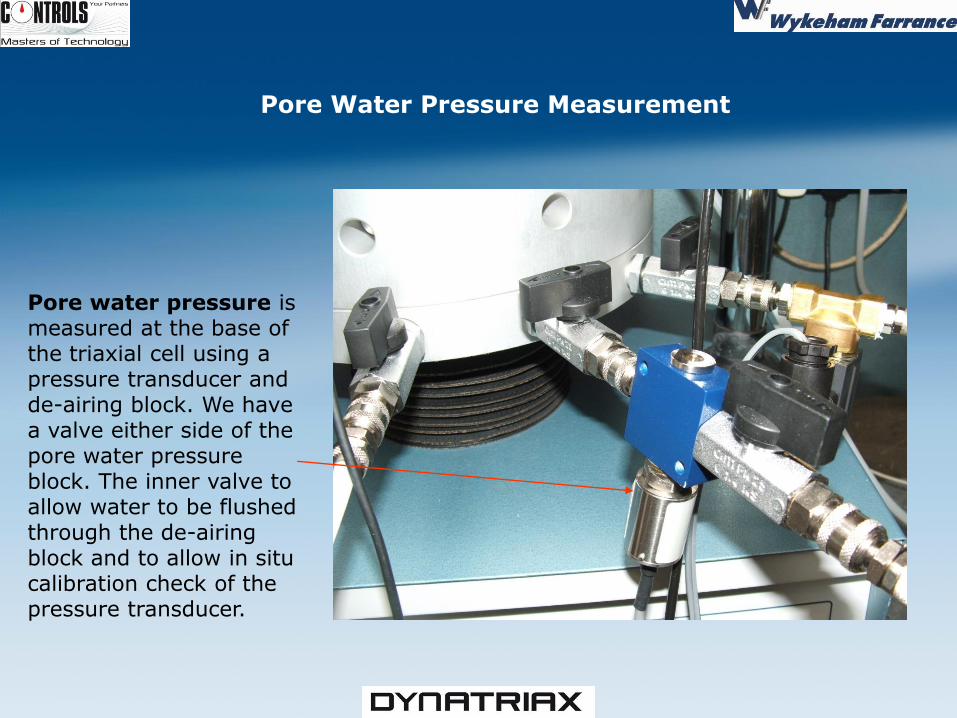
Pore water pressure is measured at the base of the triaxial cell using a pressure transducer and de-airing block. We have a valve either side of the pore water pressure block. The inner valve to allow water to be flushed through the de-airing block and to allow in situ calibration check of the pressure transducer.
Pore Water Pressure Measurement
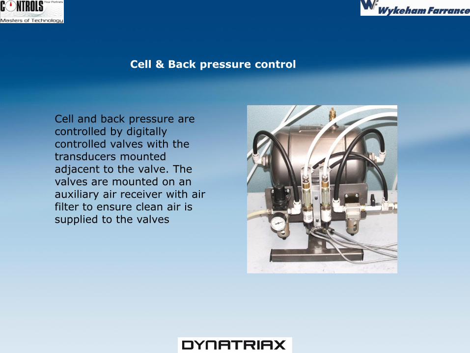
Cell and back pressure are controlled by digitally controlled valves with the transducers mounted adjacent to the valve. The valves are mounted on an auxiliary air receiver with air filter to ensure clean air is supplied to the valves
Cell & Back pressure control
27
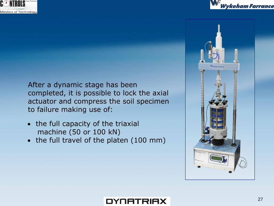
After a dynamic stage has been completed, it is possible to lock the axial actuator and compress the soil specimen to failure making use of: the full capacity of the triaxial machine (50 or 100 kN) the full travel of the platen (100 mm)
SOFTWARE
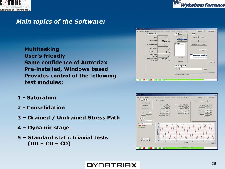
Main topics of the Software:
Multitasking
User’s friendly
Same confidence of Autotriax
Pre-installed, Windows based
Provides control of the following
test modules:
1 - Saturation
2 - Consolidation
3 – Drained / Undrained Stress Path
4 – Dynamic stage
5 – Standard static triaxial tests (UU – CU – CD)
29
Main features Allows the user manual or automatic control of the Cyclic Triaxial system in order to perform the following stages of a triaxial test: • Saturation by increments of cell pressure with B value checks • Saturation by back pressure increments with volume change measurement • Saturation by a drained ramp to a pre-defined cell pressure and back pressure, with volume change measurement • Isotropic consolidation with automatic management of the volume change device to ensure continuous measurement of volume change • Undrained or drained load controlled ramp to pre-defined load/stress or displacement/strain controlled cyclic shear • Undrained or drained monotonic shear in compression or extension
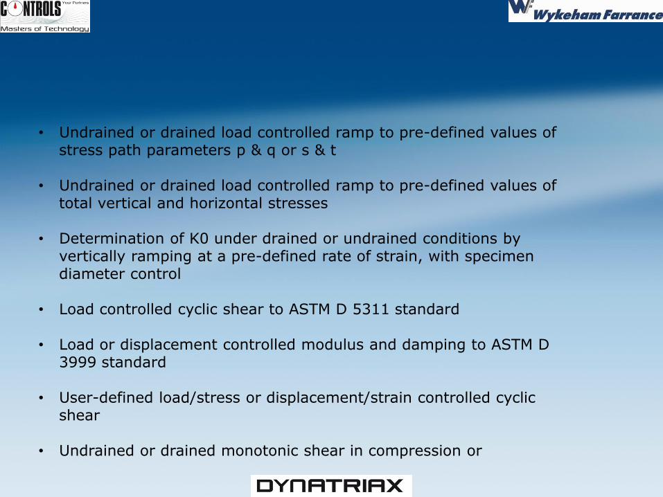
• Undrained or drained load controlled ramp to pre-defined values of stress path parameters p & q or s & t • Undrained or drained load controlled ramp to pre-defined values of total vertical and horizontal stresses • Determination of K0 under drained or undrained conditions by vertically ramping at a pre-defined rate of strain, with specimen diameter control • Load controlled cyclic shear to ASTM D 5311 standard • Load or displacement controlled modulus and damping to ASTM D 3999 standard • User-defined load/stress or displacement/strain controlled cyclic shear • Undrained or drained monotonic shear in compression or
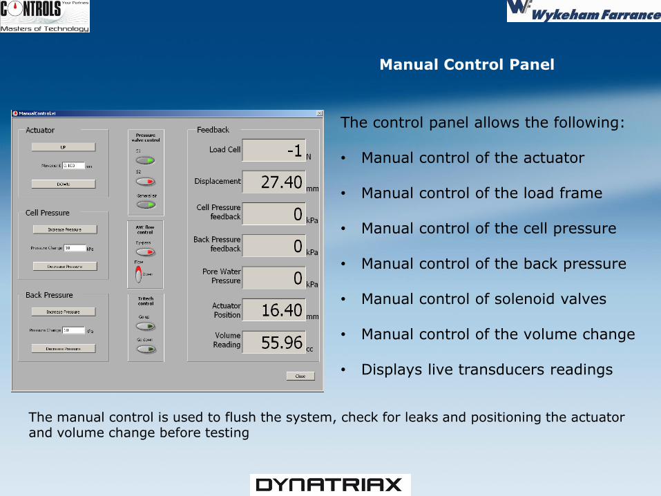
Manual Control Panel
The control panel allows the following: • Manual control of the actuator • Manual control of the load frame • Manual control of the cell pressure • Manual control of the back pressure • Manual control of solenoid valves • Manual control of the volume change • Displays live transducers readings
The manual control is used to flush the system, check for leaks and positioning the actuator and volume change before testing
33
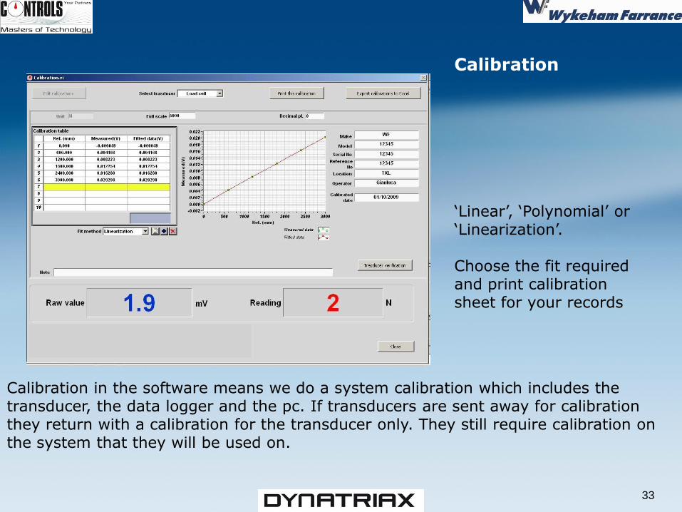
Calibration in the software means we do a system calibration which includes the transducer, the data logger and the pc. If transducers are sent away for calibration they return with a calibration for the transducer only. They still require calibration on the system that they will be used on.
Calibration ‘Linear’, ‘Polynomial’ or ‘Linearization’. Choose the fit required and print calibration sheet for your records
34
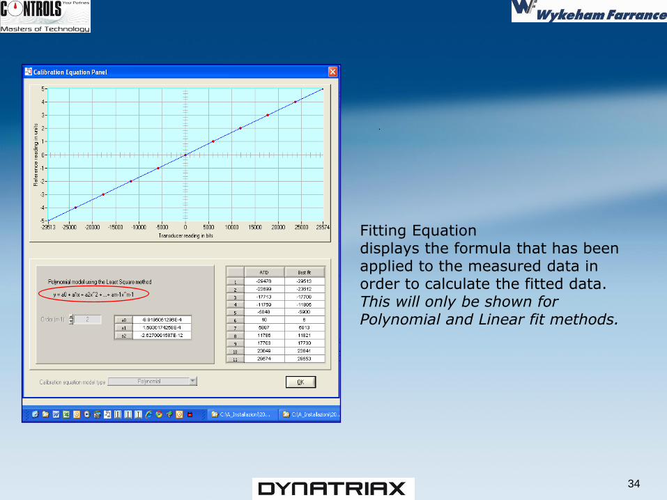
Fitting Equation displays the formula that has been applied to the measured data in order to calculate the fitted data. This will only be shown for Polynomial and Linear fit methods.
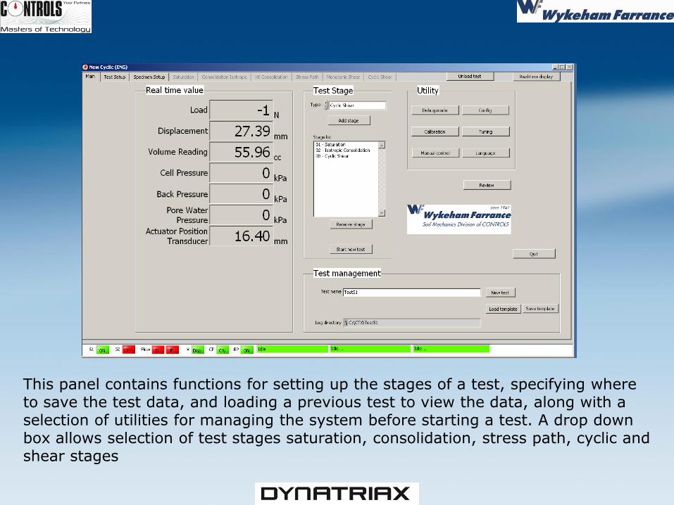
This panel contains functions for setting up the stages of a test, specifying where to save the test data, and loading a previous test to view the data, along with a selection of utilities for managing the system before starting a test. A drop down box allows selection of test stages saturation, consolidation, stress path, cyclic and shear stages
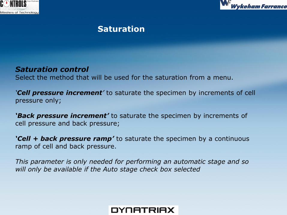
Saturation control Select the method that will be used for the saturation from a menu. ‘Cell pressure increment’ to saturate the specimen by increments of cell pressure only; ‘Back pressure increment’ to saturate the specimen by increments of cell pressure and back pressure; ‘Cell + back pressure ramp’ to saturate the specimen by a continuous ramp of cell and back pressure. This parameter is only needed for performing an automatic stage and so will only be available if the Auto stage check box selected
Saturation
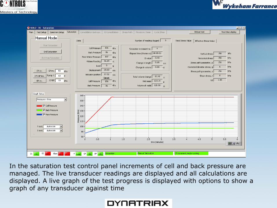
In the saturation test control panel increments of cell and back pressure are managed. The live transducer readings are displayed and all calculations are displayed. A live graph of the test progress is displayed with options to show a graph of any transducer against time
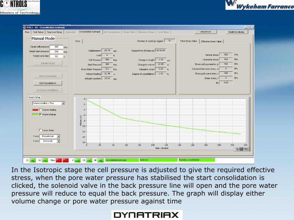
In the Isotropic stage the cell pressure is adjusted to give the required effective stress, when the pore water pressure has stabilised the start consolidation is clicked, the solenoid valve in the back pressure line will open and the pore water pressure will reduce to equal the back pressure. The graph will display either volume change or pore water pressure against time
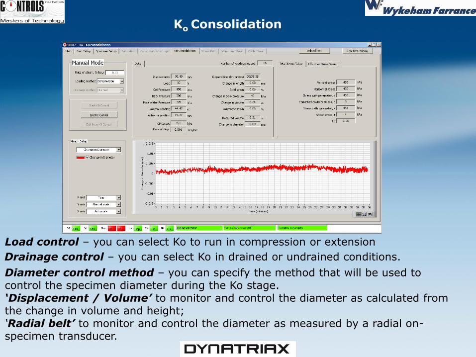
Load control – you can select Ko to run in compression or extension Drainage control – you can select Ko in drained or undrained conditions. Diameter control method – you can specify the method that will be used to control the specimen diameter during the Ko stage. ‘Displacement / Volume’ to monitor and control the diameter as calculated from the change in volume and height; ‘Radial belt’ to monitor and control the diameter as measured by a radial on-specimen transducer.
Ko Consolidation
Monotonic Shear
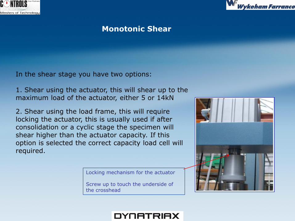
In the shear stage you have two options: 1. Shear using the actuator, this will shear up to the maximum load of the actuator, either 5 or 14kN
2. Shear using the load frame, this will require locking the actuator, this is usually used if after consolidation or a cyclic stage the specimen will shear higher than the actuator capacity. If this option is selected the correct capacity load cell will required.
Locking mechanism for the actuator Screw up to touch the underside of the crosshead
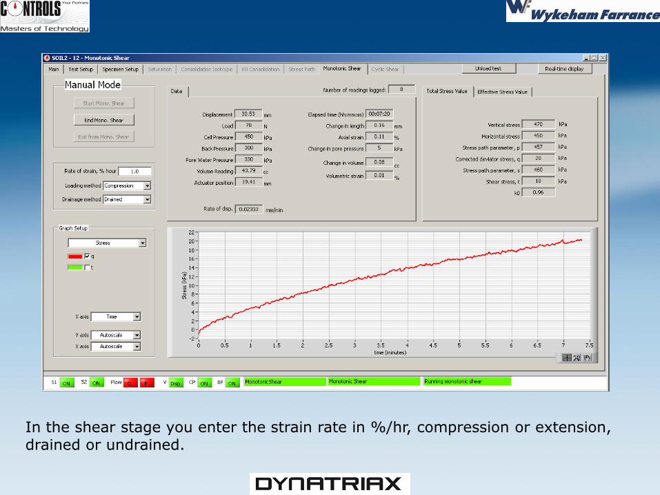
In the shear stage you enter the strain rate in %/hr, compression or extension, drained or undrained.
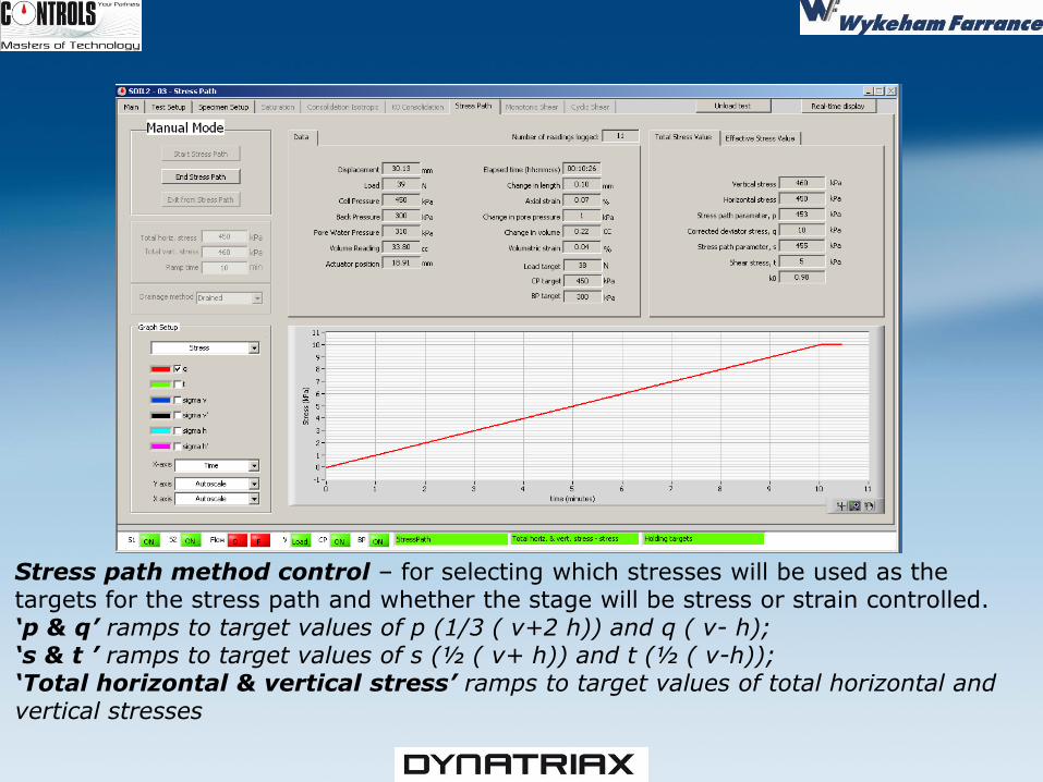
Stress path method control – for selecting which stresses will be used as the targets for the stress path and whether the stage will be stress or strain controlled. ‘p & q’ ramps to target values of p (1/3 ( v+2 h)) and q ( v- h); ‘s & t ’ ramps to target values of s (½ ( v+ h)) and t (½ ( v-h)); ‘Total horizontal & vertical stress’ ramps to target values of total horizontal and vertical stresses
Cyclic shear control – for selecting the method for the cyclic stage from: - ASTM D 5311 Load Controlled Cyclic Strength Test - ASTM D 3999 Load Controlled Modulus and Damping Test - ASTM D 3999 Displacement Controlled Modulus and Damping Test - Non standard (multi cycle test) to cycle the specimen with user-defined control modes, wave shapes and number of cycles. - Non standard (single cycle test) to cycle the specimen with user-defined control modes and wave shapes, with the number of test cycles fixed to one. - Waveshape control – for selecting a wave shape for the cyclic loading. select from ‘Sinusoidal’, ‘Triangle’, ‘Square’ or ‘User defined’. (A user defined wave shape is selected using the User waveform cell
- User waveform cell – for loading in a pre-defined wave shape file. A wave shape file is a .udw file, which is created using the program ‘UDW Generator’ that accompanies this software. This function is only available if you have selected ‘User defined’ for the
44
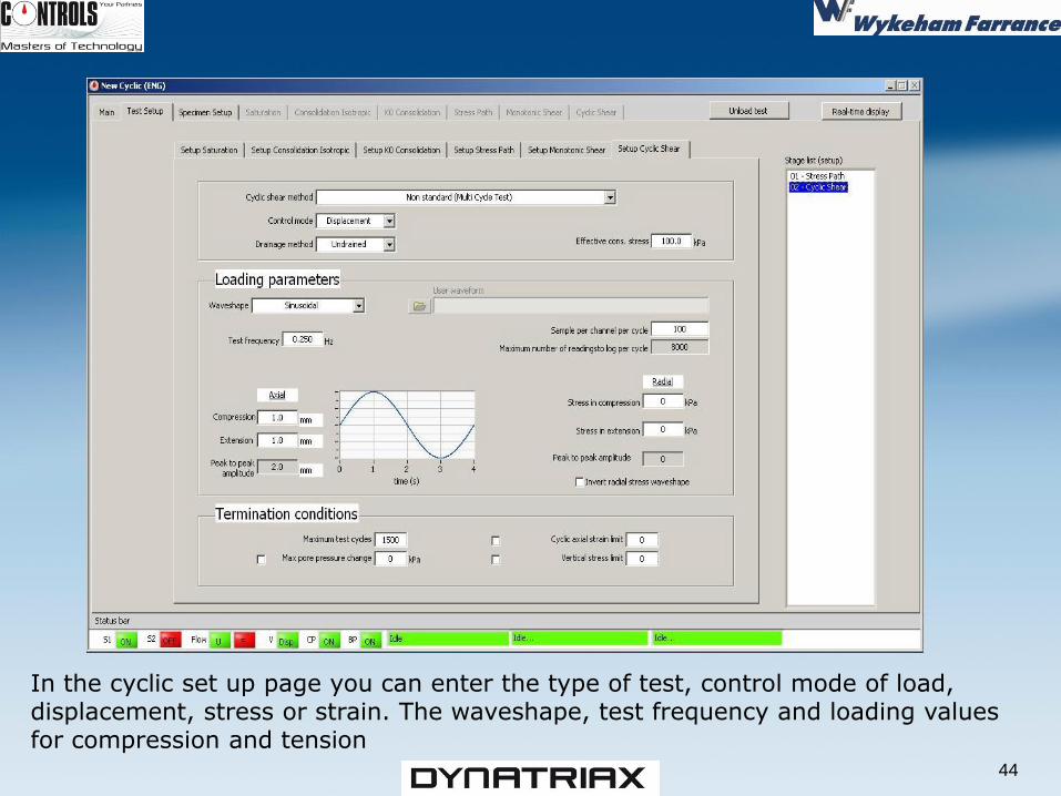
In the cyclic set up page you can enter the type of test, control mode of load, displacement, stress or strain. The waveshape, test frequency and loading values for compression and tension
45
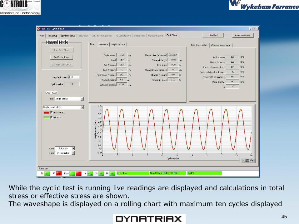
While the cyclic test is running live readings are displayed and calculations in total stress or effective stress are shown. The waveshape is displayed on a rolling chart with maximum ten cycles displayed
46
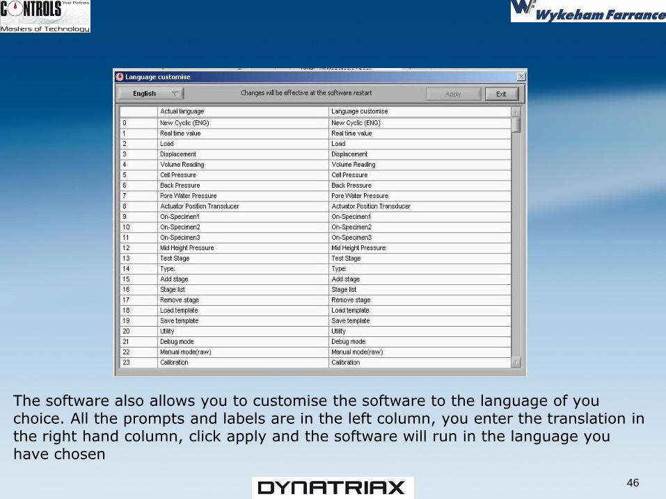
The software also allows you to customise the software to the language of you choice. All the prompts and labels are in the left column, you enter the translation in the right hand column, click apply and the software will run in the language you have chosen
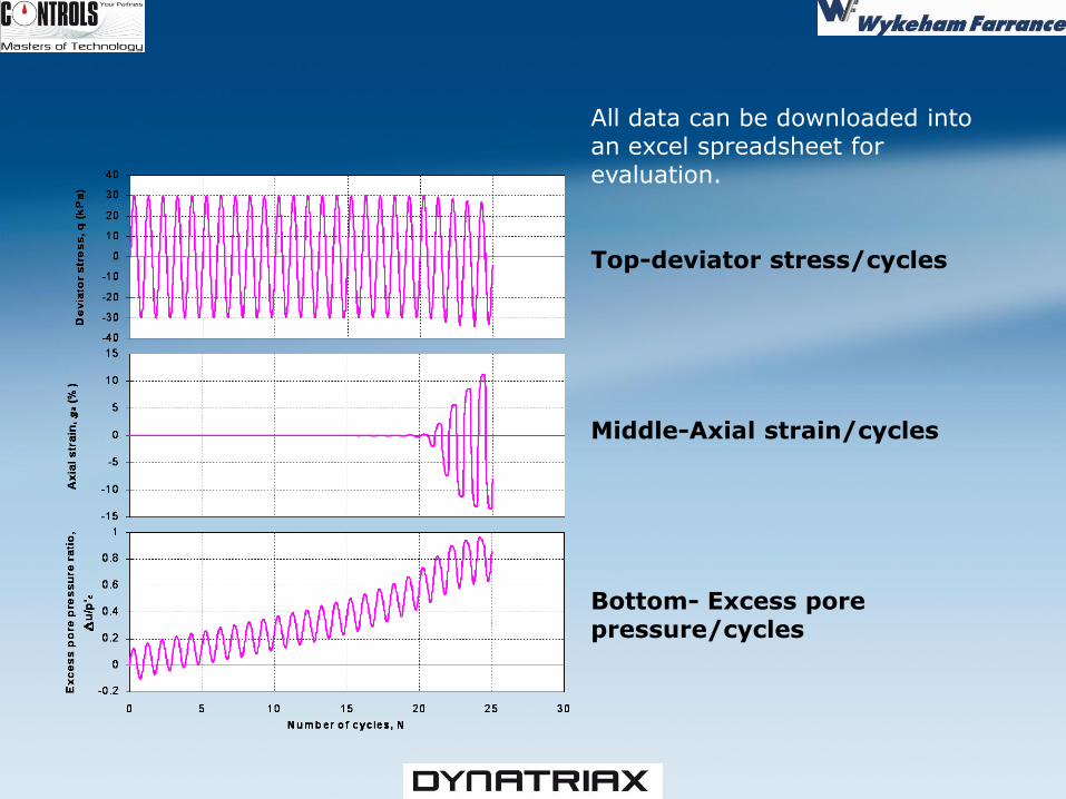
All data can be downloaded into an excel spreadsheet for evaluation. Top-deviator stress/cycles Middle-Axial strain/cycles Bottom- Excess pore pressure/cycles
UNSATURATED
SOILS TESTING
An upgrade for testing Unsaturated Soils is available consisting of the following
31-WF7000/UNS
-Includes the additional servo valve for air pressure
control and software to automatically perform the test stages by the axis
translation method:
-Saturation, Consolidation, Stress Path, Ko, Monotonic Shear, Cyclic Shear and
Soil Water Characteristic Curve
Stages are all available
-Test data recording for each stage
-All data can be downloaded to a spreadsheet
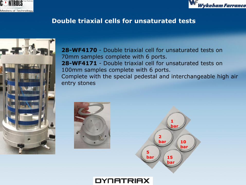
Double triaxial cells for unsaturated tests
28-WF4170 - Double triaxial cell for unsaturated tests on 70mm samples complete with 6 ports. 28-WF4171 - Double triaxial cell for unsaturated tests on 100mm samples complete with 6 ports. Complete with the special pedestal and interchangeable high air entry stones
1 bar
2 bar
5 bar
10 bar
15 bar
The Unsaturated Test Software
The software is the same as the Dynatriax software with the addition of air pressure control in all consolidation stages. The software includes a stage for Soil Water Characteristic Curve determination
The following slides will show the differences between the two cyclic software's
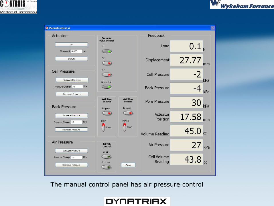
The manual control panel has air pressure control
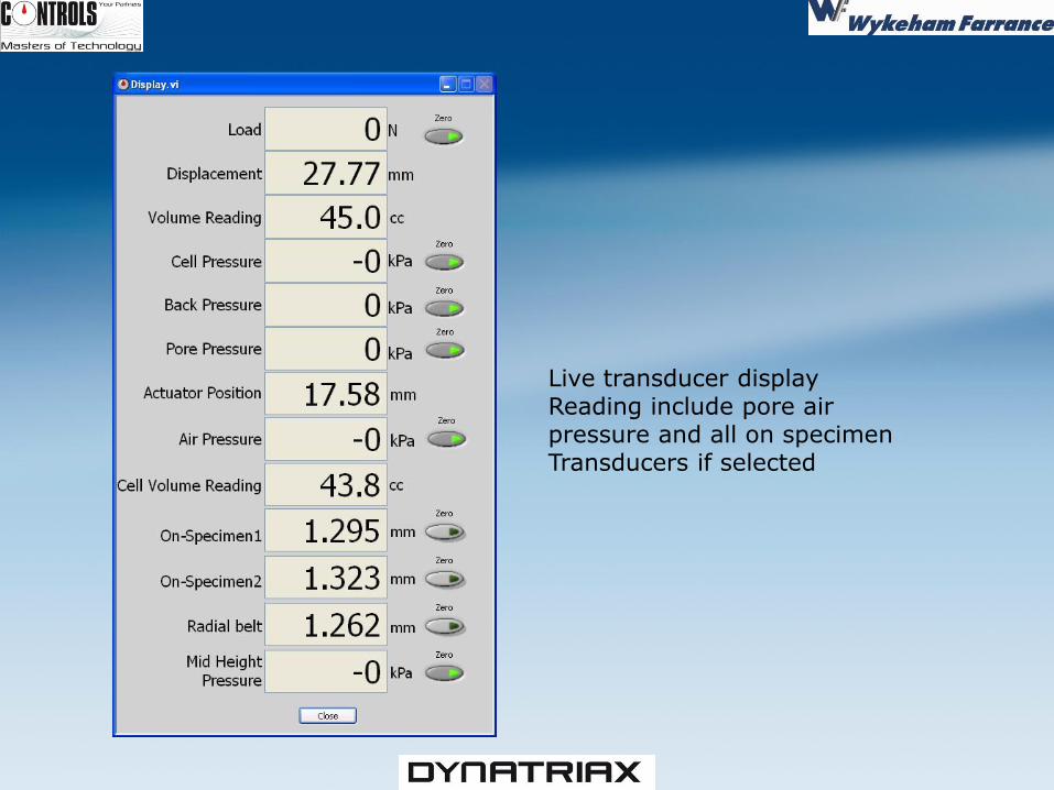
Live transducer display Reading include pore air pressure and all on specimen Transducers if selected
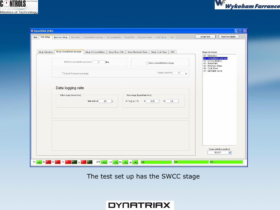
The test set up has the SWCC stage
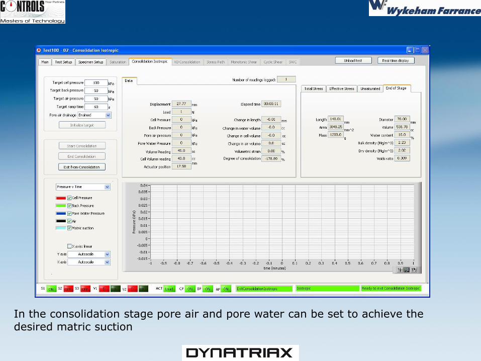
In the consolidation stage pore air and pore water can be set to achieve the desired matric suction
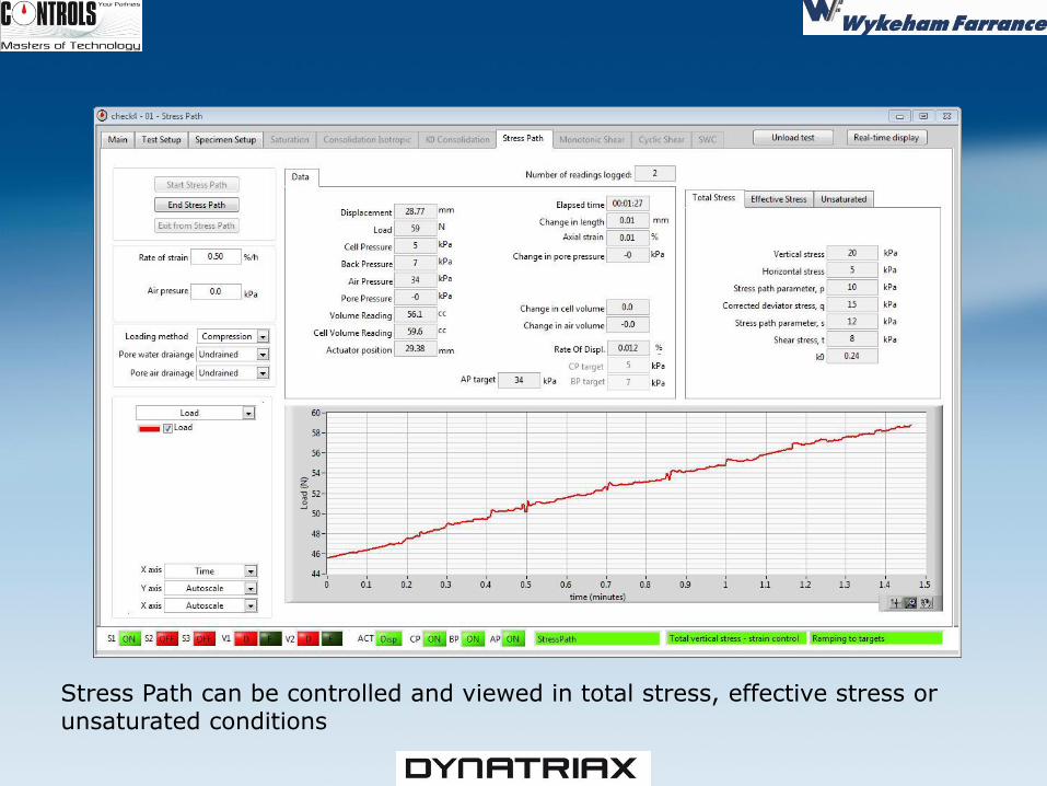
Stress Path can be controlled and viewed in total stress, effective stress or unsaturated conditions
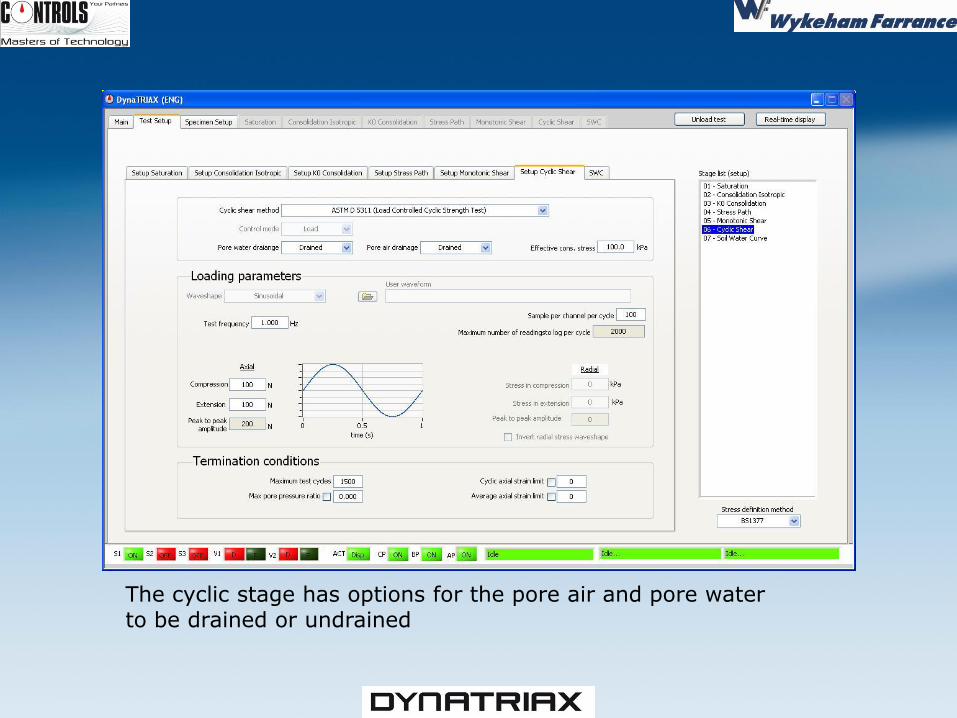
The cyclic stage has options for the pore air and pore water to be drained or undrained
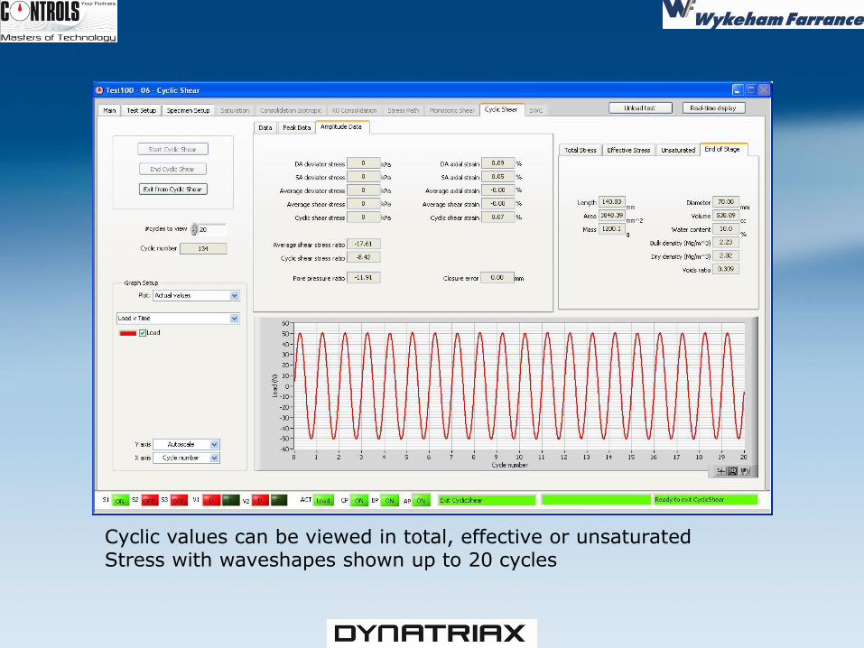
Cyclic values can be viewed in total, effective or unsaturated Stress with waveshapes shown up to 20 cycles
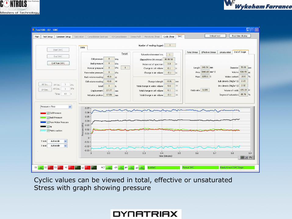
Cyclic values can be viewed in total, effective or unsaturated Stress with graph showing pressure
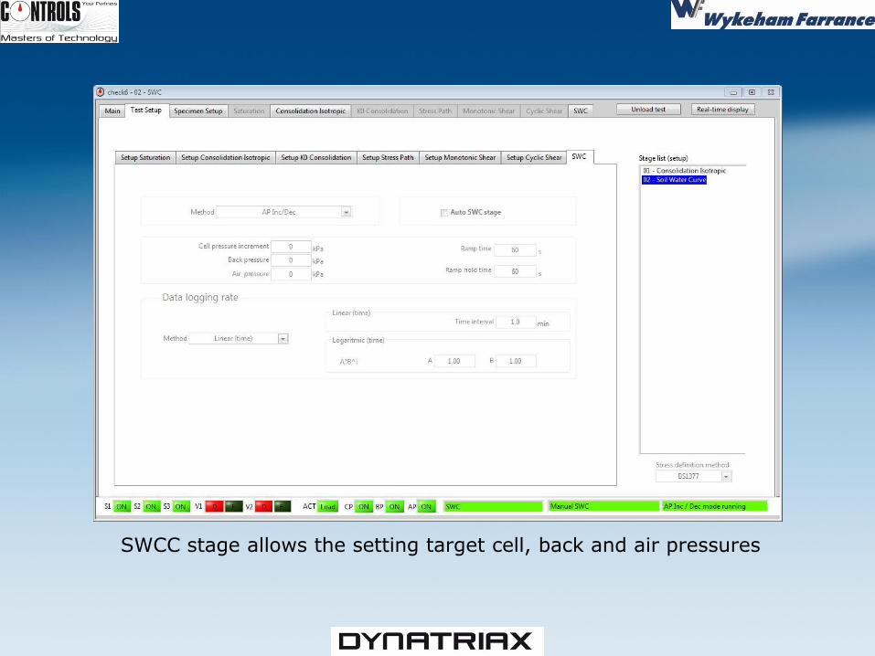
SWCC stage allows the setting target cell, back and air pressures
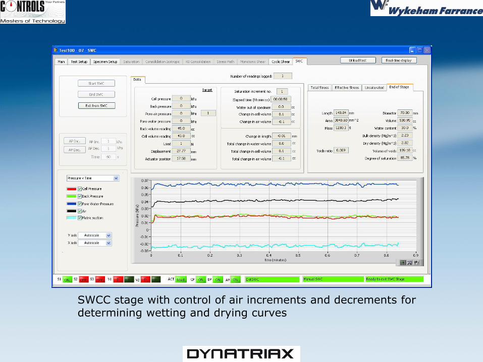
SWCC stage with control of air increments and decrements for determining wetting and drying curves
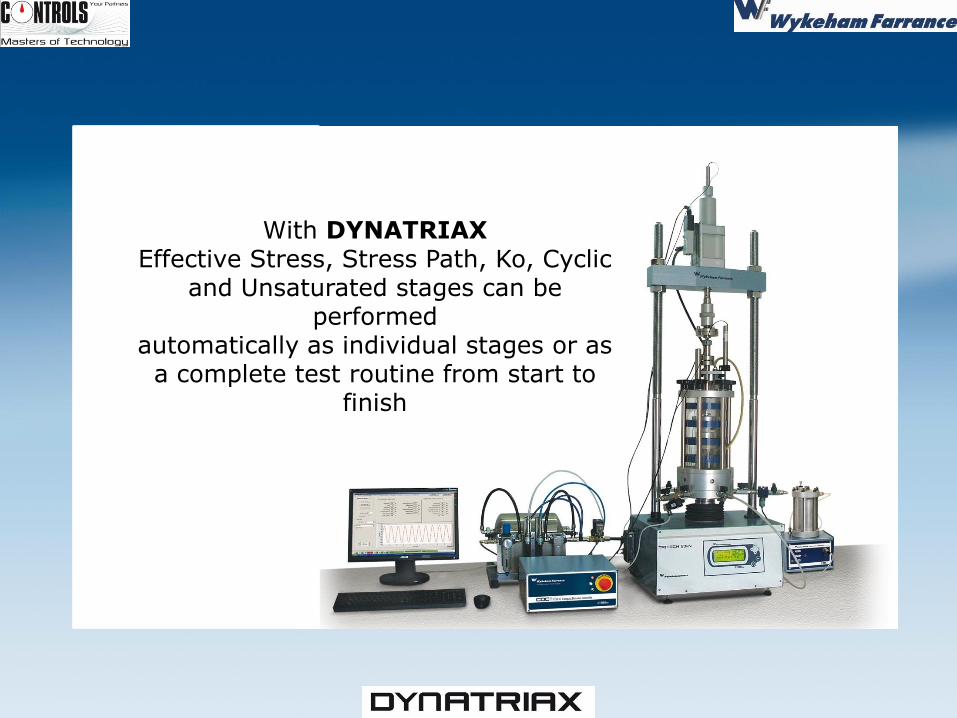
With DYNATRIAX Effective Stress, Stress Path, Ko, Cyclic
and Unsaturated stages can be performed
automatically as individual stages or as a complete test routine from start to
finish