Embed Size (px)
Citation preview

Original Article
Dynamic assessment of the seismic isolation influence for variousaircraft impact loads on the CPR1000 containment
Runyu Mei a, b, Jianbo Li a, b, *, Gao Lin a, b, Xiuyun Zhu c
a State Key Laboratory of Coastal and Offshore Engineering, Dalian University of Technology, Dalian 116024, Chinac Plant Site and Civil Engineering Department, Nuclear and Radiation Safety Center, Ministry of Environmental Protection of PRC, Beijing, 100082, China
a r t i c l e i n f o
Article history:Received 25 April 2018Received in revised form29 July 2018Accepted 4 August 2018Available online 6 August 2018
Keywords:CPR1000 containmentSeismic isolation bearingAircraft impactDynamic behavior
a b s t r a c t
An aircraft impact (AI) on a nuclear power plant (NPP) is considered to be a beyond-design-basis eventthat draws considerable attention in the nuclear field. As some NPPs have already adopted the seismicisolation technology, and there are relevant standards to guide the application of this technology infuture NPPs, a new challenge is that nuclear power engineers have to determine a reasonable method forperforming AI analysis of base-isolated NPPs. Hence, dynamic influences of the seismic isolation on thevibration and structural damage characteristics of the base-isolated CPR1000 containment are studiedunder various aircraft loads. Unlike the seismic case, the impact energy of AI is directly impacting on thesuperstructure. Under the coupled influence of the seismic isolation and the various AI load, the flexibleisolation layer weakens the constraint function of the foundation on the superstructure, the results showthat the seismic isolation bearings will produce a large horizontal deformation if the AI load is largeenough, the acceleration response at the base-mat will also be significantly affected by the differenthorizontal stiffness of the isolation bearing. These concerns require consideration during the design ofthe seismic isolation system.© 2018 Korean Nuclear Society, Published by Elsevier Korea LLC. This is an open access article under the
CC BY-NC-ND license (http://creativecommons.org/licenses/by-nc-nd/4.0/).
1. Introduction
In the event of an extreme accident, such as an earthquake, alarge fire, or an aircraft impact (AI), the safety and integrity ofnuclear power plants (NPPs) should be ensured, and the release ofradioactive materials should be precluded. Since the 9/11 incident,the United States has promulgated several regulations, such as [1]and has decided that the design of new NPPs must be evaluatedagainst hostile impacts from large-scale commercial aircraft. Theresearch pertaining to AIs on NPPs was initiated by Ref. [2]. Thefollowing scholars' research is mainly from the following researchperspectives: the global structural damage, local structural dam-age, and effects of fuel-initiated fires, as well as the functionalfailure of the structures, systems, and components (SSCs) due tothe induced vibrations in the structural members and safetyrelated equipment [3].
[4] used the forceetime history method and missileetargetinteraction method to analyze the vibration characteristic of theNPP under an impact by a 747-400 aircraft, and the sensitivity of theresults on the assumed Riera force-loading area was evaluated. [5]analyzed the impact of the tendon prestressing, impact angle, andimpact position on the impact load and dynamic response of thecontainment. [6] conducted a safety assessment of an A92 reactorbuilding under a Boeing 747 impact by analyzing different param-eters through a multistep process. [7] conducted a comprehensivereview of the AI analyses of nuclear-safety-related concrete struc-tures. [8] appraised the vibration safety of the internal equipmentand components in the primary auxiliary buildings. [9] and [10]analyzed the influence of an induced fire from an AI on the outercontainment of an NPP. [11] and [12] have done a study of the me-chanical properties of reactor pressure vessels under thermal shock,which can be applied to the thermal stress analysis induced by a firecaused by AI. In an AI evaluation, the NPP is often assumed to be astructure without a seismic isolation system, and the boundaryconditions are generally considered to be fixed boundaries.
The previous nuclear accidents caused by strong earthquakes,such as the Kashiwazaki Kariwa nuclear accident in July 2007 andthe Fukushima nuclear accident in March 2011, have directly led to
b Institute of Earthquake Engineering, Dalian University of Technology, Dalian116024, Liaoning, China* Corresponding author. No.2 Linggong Road, Ganjingzi District, Dalian City,Liaoning Province, China.
E-mail address: [email protected] (J. Li).
Contents lists available at ScienceDirect
Nuclear Engineering and Technology
journal homepage: www.elsevier .com/locate/net
https://doi.org/10.1016/j.net.2018.08.0031738-5733/© 2018 Korean Nuclear Society, Published by Elsevier Korea LLC. This is an open access article under the CC BY-NC-ND license (http://creativecommons.org/licenses/by-nc-nd/4.0/).
Nuclear Engineering and Technology 50 (2018) 1387e1401

a substantial increase in the current seismic fortification standardsfor NPPs. Thus, the NPP designers doubt the aseismic capabilities oftraditional earthquake resistance measures. Seismic isolation isproven as an effective technology for reducing the seismic responseof a superstructure from its base to negotiate the destructivegroundmovement. The guidance for the seismic isolation of NPPs ispresently available in ASCE4-16 and other relevant standards.Seismic isolation has been deployed in the NPPs of France andSouth Africa, thus, generating a new concern regarding the impactanalysis of an aircraft on a base-isolated NPP. [13] noted that anNRC-funded research project studied the topic of AI analyses forseismically isolated nuclear structures and stated that the safety ofthe isolated structures under an AI should be evaluated. Currently,there is little research pertaining to this aspect of AI analyses.
For an NPP with a seismic isolation system, the flexible isolationlayer weakens the constraint function of the foundation to thesuperstructure. The seismic energy that is transmitted from theunderground region to the superstructure is weakened by isolator,shown in Fig. 1(a). Unlike the seismic load case, the aircraft loadcase consists of a short-duration impact occurring in a singlearbitrary direction in space on superstructure, shown in Fig. 1(b).The impact energy is directly acting on the superstructure. Underthe impact of such loads, the influence of isolation bearings on thedynamic behavior of NPPs is needed to be studied, such as the localdamage of the containment and the vibration response of the NPPs.
In this study, the dynamic characteristics of the base-isolatedCPR1000 containment under AI are analyzed, and based on theseresults, a reasonable analysis model is proposed. This paper isorganized into the following sections. Section 2 establishes arepresentative detailed three-dimensional (3D) model of theCPR1000 containment. A series of six isolation bearings areselected, and the isolation performance of each isolation bearing isanalyzed and verified in Section 3. An AI containment analysis isconducted with the six isolation bearings. In Section 4, based on the3D finite element (FE) model of the containment, three different AIloads are considered. The distributions of the concrete plasticstrain, displacement response of the containment, and accelerationresponse of the containment are analyzed. Finally, the conclusionsare presented in Section 5.
2. Geometric and 3D FE modeling of the containment
2.1. Geometric modeling of the containment
The structure of the CPR1000 pressurized water reactor is
illustrated in Fig. 2 and is mainly composed of three parts: theconcrete containment, steel lining, and prestressed reinforcement.The concrete containment includes the base mat, cylinder, anddome. The inner diameter of the containment is 37 m, the height ofthe cylinder is 50.11m, the total height from the bottom of the plateto the dome is 66.68 m, the normal thickness of the dome is 0.8 m,and the normal wall thickness of the cylinder is 0.9 m. Two layers ofthe circumferential and vertical prestressed reinforcement areshown in Fig. 4 and Fig. 5, respectively. The upper end of the verticalprestressed reinforcement is anchored at the top surface of the ringbeam, and the lower end is anchored to the base mat of thecontainment. In addition, three layers of prestressed reinforcement,which are anchored on the ring beam, are arranged in the dome.The inner side of the concrete containment structure is also con-nectedwith a layer of 6mm thick steel lining, which is connected tothe concrete containment with rivets.
2.2. FE modeling of the containment
2.2.1. Concrete constitutive modelWhen conducting a structural dynamic analysis, a proper and
reliable model that can reflect the concrete material behavior athigh strain rates is needed. [15] used the Winfrith concrete modelto simulate the impact resistance of steel-plate concrete and rein-forced concrete panels. [16] used the plasticity concrete model tosimulate an AI on the concrete containment. [8] evaluated the vi-bration safety of the primary auxiliary buildings using the CSCMconcrete model. In this study, the plasticity concrete model isselected. This model includes the damage and strain rate effectsand has been widely used for modeling concrete members subject
Fig. 1. The schematic diagram of an NPP with seismic isolation under a seismic load and AI.
Fig. 2. CPR1000 containment.
R. Mei et al. / Nuclear Engineering and Technology 50 (2018) 1387e14011388

to high-velocity impacts, such as projectile perforation, reinforcedconcrete targets, and AI on a concrete containment.
This concrete model decouples the volumetric and deviatoricresponses of concrete. The volumetric response is easily capturedvia a tabulated input which gives the current pressure as a functionof current and previous minimum (most compressive) volumetricstrain. A three-failure-surface model is used to analyze deviatoricresponses, as shown in Fig. 6. During initial loading or reloading,the deviatoric stresses remain elastic until the stress reaches theinitial yield surface. The deviatoric stresses can then further in-crease until the maximum yield surface is reached. Beyond thisstage the response can be perfectly plastic or soften to the residualyield surface [17]. a0y, a1y, a2y, a0, a1, a2, a1f , a2f are material con-stants. Mean stress P ¼ � ðs1 þ s2 þ s3Þ=3. s1, s2, s3 are the first,second and third principal stresses respectively.
Dsy ¼ a0y þP
a1y þ a2yPðinitial yield surfaceÞ; (1)
Dsm ¼ a0 þP
a1 þ a2Pðmaximum yield surfaceÞ; (2)
Dsr ¼ Pa1f þ a2f P
ðresidual yield surfaceÞ; (3)
In Eq. (4), after reaching the initial yield surface but before themaximum failure surface, the current surface Dsf is obtained as alinear interpolation between Dsm and Dsy. In Eq. (5), after reachingthe maximum surface the current failure surface Dsh is similarlyinterpolated between Dsm and Dsr . The function h(l) varies from0 to 1 depending on the accumulated effective plastic strainparameter l. This function would normally begin at 0 at l ¼ 0, in-crease to 1 at some value l ¼ lm, and then decrease to 0 at somelarger value of l. lm is defined simply as the value of l corre-sponding to the first relative maximum of h. Based on this, theelasticity, plasticity and softening deformation of concrete can bequalitatively described.
Dsf ¼ hDsm þ ð1� hÞDsy; (4)
and
Dsh ¼ hDsm þ ð1� hÞDsr; (5)
The main advantage of this model is that one user input isrequired, the unconfined compressive strength. Other parametersare automatically generated within the program. The requiredconcrete parameters include the density (r ¼ 2500 kg=m3Þ, Pois-son's ratio ðn ¼ 0:2Þ; uniaxial compressive strength ðfc ¼ 41 MPa),and uniaxial tensile strength ðf t ¼ 2:85 MPaÞ [18].
To consider the strain rate effect of concrete, a dynamic increasefactor (DIF) is introduced in this study. The DIF represents the ratioof the dynamic-to-static strength versus the strain rate. The DIF ofthe compressive strength for CEB is given in Eq. (6) and Eq. (7)[19,20].
CDIF ¼ fcdfcs
¼�_εd_εcs
�1:026a_εd � 30s�1 (6)
and
CDIF ¼ fcdfcs
¼ gð_εdÞ1=3 _εd >30s�1; (7)
where fcd is the dynamic compressive strength at the strain rate _εd;fcs is the static compressive strength at strain rate _εcsð_εcs ¼ 30�10�6s�1Þ; logg ¼ 6:156a� 0:49 and a ¼ ð5þ 3fcu=4Þ�1; fcu is thestatic compressive strength.
The DIF of concrete the tensile strength is determined by Eq. (8)and Eq. (9).
TDIF ¼ ftdfts
¼�_εd_εts
�d
_εd � 1s�1 (8)
and
TDIF ¼ ftdfts
¼ b
�_εd_εs
�1=3_εd � 1s�1; (9)
where ftd is the dynamic tensile strength at the strain rate _εd; fts isthe static tensile strength at the strain rate _εtsð_εts ¼ 1Þ; log b ¼ 6d�2, d ¼ 1=1þ 8f ‘c=f
‘co; and f ‘co ¼ 10MPa; f ‘c is the static tensile
strength.This constitutivemodel was used in the latest LS-DYNA software
code [14], corresponding to keyword cardMat_Concrete_Damage_Rel3.
Fig. 3. FE model of the CPR1000 containment.
Fig. 4. Positive view of the prestressed reinforcement.
Fig. 5. Top view of the prestressed reinforcement.
R. Mei et al. / Nuclear Engineering and Technology 50 (2018) 1387e1401 1389

2.2.2. Metal structural modelFig. 7 shows the elasticeplastic model with the kinematic
hardening material model that is used to model the behavior of theprestressed reinforcement and steel lining. In this paper, kinematichardening of the metal was considered by setting the parameterb ¼ 0. The prestressed reinforcement is embedded in the concreteusing the option *CONSTRAINED_LARGRANGE_IN_SOLID. Thismethod does not require the consideration of complex reinforce-ment modeling problems, while maintaining good accuracy andstability. The steel lining and concrete structure are closely con-nected by rivets. The steel liner is simulated by shell elements withsix degrees of freedom per node, and the concrete is simulated bysolid elements with three degrees of freedom per node. Consid-ering the difference in the nodal degrees of freedom for the twoelements, the keyword *CONTACT_TIED_NODES_TO_SURFACE isused to simulate the close connection between the steel lining andconcrete surface.
In this study, the yield strength of the rebar and structural steelis highly dependent upon the strain rate. The yield strength in-creases when the strain rate increases. This dynamic yield strengthof steel is taken into consideration by the CowpereSymonds for-mula for uniaxial tension or compression, as shown in Eq. (10).
sdsy
¼ 1þ�_ε
C
�1P
; (10)
where sd is the dynamic yield strength; sy is the static yieldstrength; _ε is the strain rate; C and P are the constants of theCowpereSymonds relation. The material parameters of the pre-stressed reinforcement and steel lining are presented in Table 1[21].
2.2.3. Summary of the FE containment modelAccording to the above analysis, the detailed FEmodel, shown in
Fig. 3, is established by using the ANSYS16.0/LS-DYNA software[14]. The main components of the containment are simulated. Theconcrete is simulated by solid164 with multilayered solid elementsalong the radial direction; the steel lining is simulated by shell163;the prestressed reinforcement is simulated by link160, and theprestress load is added by applying an initial stress to the linkelement [22].
In order to verify the rationality of this concrete constitutivemodel, metal structural model and the corresponding materialparameters, such as the C and P of the steel bar, the impact tests of a1/7.5 ratio GE J79 engine with 215 m/s impact velocity on 12 cmthick reinforced concrete target plate conducted by Muto in 1989[23] are simulated. The FE model of the engine and reinforcedconcrete target plate are shown in Fig. 8. The coupling interactionbetween steel bar and concrete in reinforced concrete plate adoptsthe keyword of *CONSTRAINED_LARGRANGE_IN_SOLID. Both thematerial model of steel bar and engine adopt the Plastic Kinematicmodel. Lastly, 304,164 elements are used for the entire model. Thesize of the impact hole obtained by numerical simulation is198 mm � 208 mm, which is very close to the experimental result185 mm � 195 mm, shown in Fig. 9. The residual velocity of theengine after perforate the panel is also very close to the experi-mental result 54m/s, shown in Fig.10. From the comparison results,the reinforcement coupling method used in the CPR1000 finiteelement model and the selected concrete and reinforcement ma-terial constitutive model and the corresponding material parame-ters are reasonable.
3. Seismic isolators
At present, there are several types of new and existing isolation
Fig. 6. Strength model for concrete, (a) failure surface of the concrete material model and uniaxial stress-strain relationship.
Fig. 7. The kinematic hardening material model.
Table 1Material parameters of the metal structure.
rðkg=m3Þ E/Pa n sy=Pa C P
Prestressed reinforcement 7850 1.9e11 0.3 1.77e8 641 7.3Steel lining 7850 2.06e11 0.3 3.25e8 40.4 5
R. Mei et al. / Nuclear Engineering and Technology 50 (2018) 1387e14011390

systems, such as the low damping rubber bearing (LDRB), leadrubber bearing (LRB), friction sliding isolator (FSI), high dampingrubber bearing (HDRB), and friction pendulum isolator. For elas-tomeric bearings, the behavior of the LDRB, LRB, and HDRB in shearis well established [24,25]. The mathematical model of the shearbehavior for these bearings can be simplified into a bilinearrestoring force model, as shown in Fig. 11. However, the dampingcharacteristics of these isolating bearings are considerablydifferent. For the LDRB, owing to its low viscous damping, addi-tional damping should be added during the design and construc-tion to improve the damping effect. The HDRB uses a rubber with ahigh damping property. The LRB mainly relies on the lead core toexert the damping effect of the bearing.When the dynamic analysisis conducted, the damping of the isolation bearing affects the dy-namic characteristics of the structure, especially under an AI.
This work does not involve the study and design of the isolationbearings for the CPR1000 containment according to the relevant
specifications; this study is a qualitative analysis of the influence ofthe isolation bearings on the dynamic behavior of the CPR1000containment under different AI loads. The influence of the isolationbearings on the horizontal stiffness is mainly considered, and theadditional damping is assumed to be small. In the LS-DYNA code,the isolators can be modeled by a linear spring
Fig. 8. The FE model used in the engine impact tests.
Fig. 9. Comparison of the damage of front face of panel between numerical results and experimental results (units: mm).
Fig. 10. The comparison of engine residual velocity between numerical results andexperimental results.
Fig. 11. Bilinear restoring force model.
R. Mei et al. / Nuclear Engineering and Technology 50 (2018) 1387e1401 1391
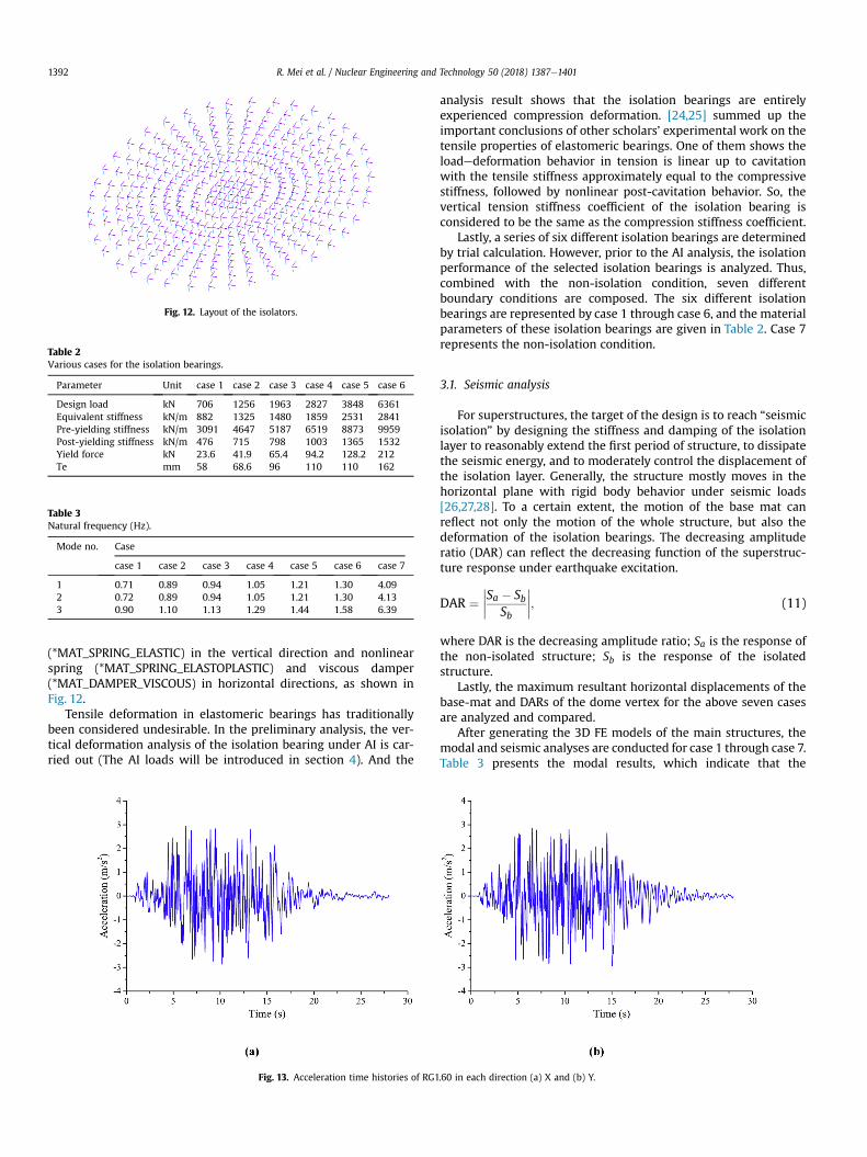
(*MAT_SPRING_ELASTIC) in the vertical direction and nonlinearspring (*MAT_SPRING_ELASTOPLASTIC) and viscous damper(*MAT_DAMPER_VISCOUS) in horizontal directions, as shown inFig. 12.
Tensile deformation in elastomeric bearings has traditionallybeen considered undesirable. In the preliminary analysis, the ver-tical deformation analysis of the isolation bearing under AI is car-ried out (The AI loads will be introduced in section 4). And the
analysis result shows that the isolation bearings are entirelyexperienced compression deformation. [24,25] summed up theimportant conclusions of other scholars’ experimental work on thetensile properties of elastomeric bearings. One of them shows theloadedeformation behavior in tension is linear up to cavitationwith the tensile stiffness approximately equal to the compressivestiffness, followed by nonlinear post-cavitation behavior. So, thevertical tension stiffness coefficient of the isolation bearing isconsidered to be the same as the compression stiffness coefficient.
Lastly, a series of six different isolation bearings are determinedby trial calculation. However, prior to the AI analysis, the isolationperformance of the selected isolation bearings is analyzed. Thus,combined with the non-isolation condition, seven differentboundary conditions are composed. The six different isolationbearings are represented by case 1 through case 6, and the materialparameters of these isolation bearings are given in Table 2. Case 7represents the non-isolation condition.
3.1. Seismic analysis
For superstructures, the target of the design is to reach “seismicisolation” by designing the stiffness and damping of the isolationlayer to reasonably extend the first period of structure, to dissipatethe seismic energy, and to moderately control the displacement ofthe isolation layer. Generally, the structure mostly moves in thehorizontal plane with rigid body behavior under seismic loads[26,27,28]. To a certain extent, the motion of the base mat canreflect not only the motion of the whole structure, but also thedeformation of the isolation bearings. The decreasing amplituderatio (DAR) can reflect the decreasing function of the superstruc-ture response under earthquake excitation.
DAR ¼����Sa � Sb
Sb
����; (11)
where DAR is the decreasing amplitude ratio; Sa is the response ofthe non-isolated structure; Sb is the response of the isolatedstructure.
Lastly, the maximum resultant horizontal displacements of thebase-mat and DARs of the dome vertex for the above seven casesare analyzed and compared.
After generating the 3D FE models of the main structures, themodal and seismic analyses are conducted for case 1 through case 7.Table 3 presents the modal results, which indicate that the
Fig. 12. Layout of the isolators.
Table 2Various cases for the isolation bearings.
Parameter Unit case 1 case 2 case 3 case 4 case 5 case 6
Design load kN 706 1256 1963 2827 3848 6361Equivalent stiffness kN/m 882 1325 1480 1859 2531 2841Pre-yielding stiffness kN/m 3091 4647 5187 6519 8873 9959Post-yielding stiffness kN/m 476 715 798 1003 1365 1532Yield force kN 23.6 41.9 65.4 94.2 128.2 212Te mm 58 68.6 96 110 110 162
Table 3Natural frequency (Hz).
Mode no. Case
case 1 case 2 case 3 case 4 case 5 case 6 case 7
1 0.71 0.89 0.94 1.05 1.21 1.30 4.092 0.72 0.89 0.94 1.05 1.21 1.30 4.133 0.90 1.10 1.13 1.29 1.44 1.58 6.39
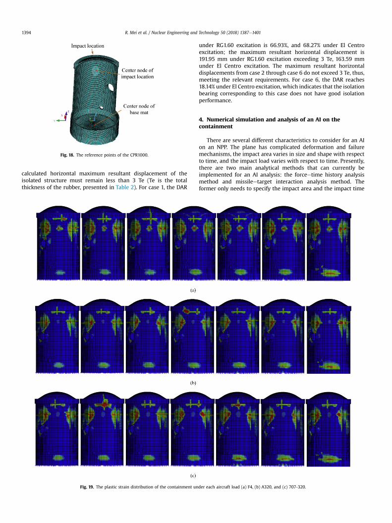
Fig. 13. Acceleration time histories of RG1.60 in each direction (a) X and (b) Y.
R. Mei et al. / Nuclear Engineering and Technology 50 (2018) 1387e14011392

vibration frequency of the structure is associated with the hori-zontal stiffness of the isolation bearings.
For the seismic analysis, two types of seismic waves areconsidered as the seismic oscillation input. Additionally, only theeffects of horizontal earthquakes are considered. One seismicoscillation input is the artificial seismic wave derived from theRegulatory Guide 1.60 reference response spectra (RG1.60), asshown in Fig. 13. The peak ground acceleration for the X and Ydirections is equal to 0.3 g. The other seismic oscillation input is theEl Centro seismic wave, as shown in Fig. 14.
Based on the numerical results, the maximum resultant dis-placements of the base mat and DAR of the dome vertex for eachcase under these two seismic loads are shown in Fig. 15. The lateralaxis in the diagram represents the first vibration period for eachcase. Considering these two types of seismic loads, the variation ofthe DAR and the maximum resultant horizontal displacement aresimilar. From case 1 to case 6, the DAR and maximum resultanthorizontal displacement will increase with an increase in the vi-bration period. The growth rate of the DAR slowly decreases, whilethe maximum resultant horizontal displacement demonstrates theopposite trend.
One of the isolation system design criteria requires that the
Fig. 14. Acceleration time histories of El Centro in the direction (a) X and (b) Y.
Fig. 15. The DAR and the maximum resultant horizontal displacement of thecontainment under different seismic loads.
Fig. 16. Reaction time response of the aircrafts.
Fig. 17. Impact location and direction.
R. Mei et al. / Nuclear Engineering and Technology 50 (2018) 1387e1401 1393
calculated horizontal maximum resultant displacement of theisolated structure must remain less than 3 Te (Te is the totalthickness of the rubber, presented in Table 2). For case 1, the DAR
under RG1.60 excitation is 66.93%, and 68.27% under El Centroexcitation; the maximum resultant horizontal displacement is191.95 mm under RG1.60 excitation exceeding 3 Te, 163.59 mmunder El Centro excitation. The maximum resultant horizontaldisplacements from case 2 through case 6 do not exceed 3 Te, thus,meeting the relevant requirements. For case 6, the DAR reaches18.14% under El Centro excitation, which indicates that the isolationbearing corresponding to this case does not have good isolationperformance.
4. Numerical simulation and analysis of an AI on thecontainment
There are several different characteristics to consider for an AIon an NPP. The plane has complicated deformation and failuremechanisms, the impact area varies in size and shape with respectto time, and the impact load varies with respect to time. Presently,there are two main analytical methods that can currently beimplemented for an AI analysis: the forceetime history analysismethod and missileetarget interaction analysis method. Theformer only needs to specify the impact area and the impact time
Fig. 18. The reference points of the CPR1000.
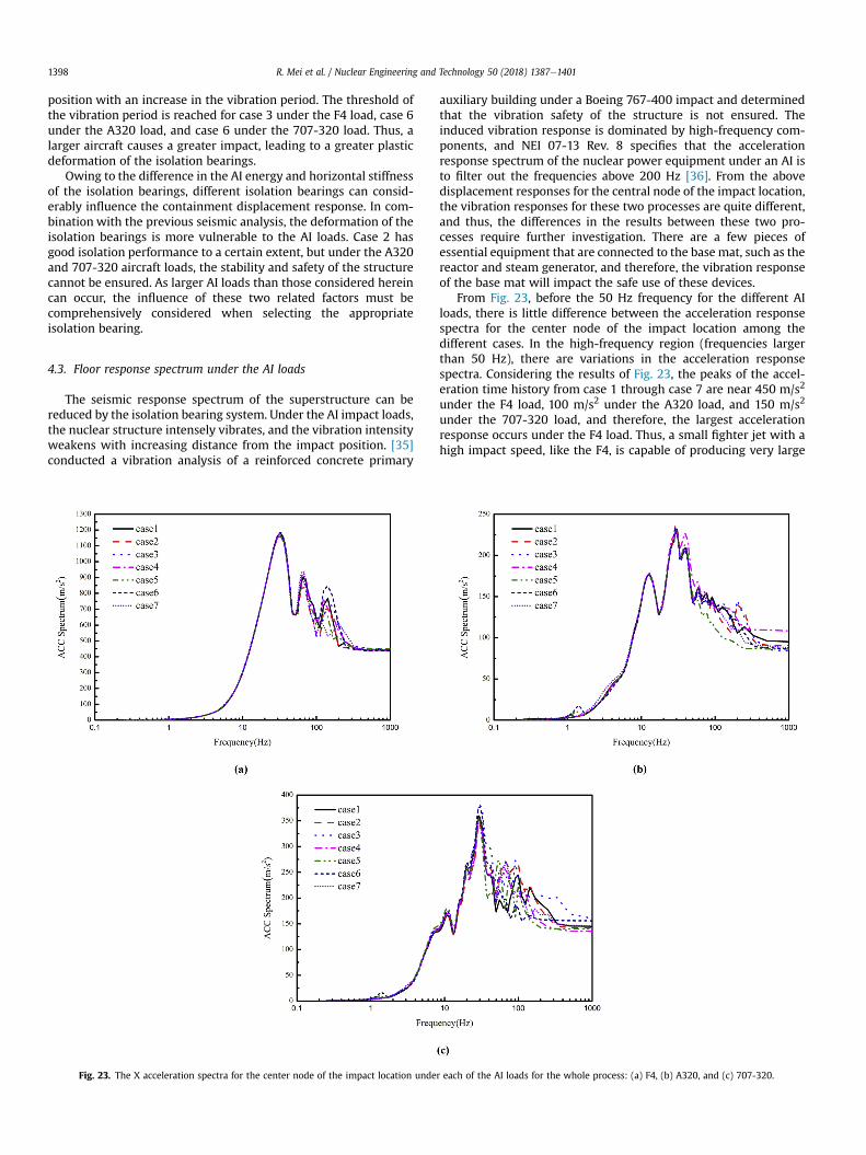
Fig. 19. The plastic strain distribution of the containment under each aircraft load (a) F4, (b) A320, and (c) 707-320.
R. Mei et al. / Nuclear Engineering and Technology 50 (2018) 1387e14011394

Fig. 20. The X displacement response of the center node of the impact location and the center node of the base mat under the impact of each aircraft load (a) F4, (b) A320, and (c)707-320.
R. Mei et al. / Nuclear Engineering and Technology 50 (2018) 1387e1401 1395

history load and does not need to build a complex three-dimensional finite element model, so that the analysis efficiencyis greatly improved. The accuracy and reliability of the resultsgenerated by this method are sensitive to the loading area andtiming of load application. [29] noted that the loading surface of theAI will influence the deflection, damaged area, and reaction force ofthe slab.
There are two main approaches to consider for calculating theimpact area. One divides the impact area into three regions: thefuselage, wing, and engine [30]. The other simplifies the impactarea into a circular area [31e34]. M.R. Sadique and Mohd. AshrafIqbal considered that when the purpose is to evaluate the globalresponse of the containment, simplifications can be made for thedetermination of contact area. They analyzed the impact area ofPhantom F4 (215 m/s), Airbus A-320 (120 m/s) and Boeing 707-320(103m/s) is a circular area of 6 in diameter, Boeing 747-400 (120m/s) and Boeing 767-400 (120 m/s) is a circular area of 12 in diameter.
Taking into account the characteristics of different AI loads,fighter Phantom F4 (215 m/s), commercial aircraft Airbus A-320(120 m/s), and Boeing 707-320 (103 m/s) are selected, which arereferred to as F4, 707-320, and A320, respectively, shown in Fig. 16.For each of the aircraft loads, the impact area is assumed to becircular with a diameter of 6 m. One impact location is considered,which is most critical location located at the junction of the domeand cylinder [33], as shown in Fig. 17. The impact direction is alsoshown in Fig. 17.
Recent research on AIs has mainly focused on the deformation,destruction, and vibration of NPPs during the aircraft collision.However, relatively little research concerning the dynamicresponse of the structure in the free attenuation vibration processhas been conducted. During this process, the vibration character-istics of a base-isolated NPP are likely to be different from those of anon-isolated structure. The isolation bearings play a major role inthe attenuation of the vibration response.
Based on the results of a trial calculation, the calculation time ofthe entire process is fixed at 3.0 s. The initial 0.2 s is the stable stageof the prestressed reinforcement with large damping. The timerange of 0.2 se3.0 s is for the dynamic calculation process, which isthe main consideration of this analysis. This main portion of theanalysis contains two processes: the AI process and vibrationattenuation process. The influence of the isolation bearings on thedynamic behavior of the containment is analyzed and compared bythe distribution of the ultimate plastic strain distribution and vi-bration response of the containment.
4.1. The plastic strain distribution of the concrete containment
Fig. 19 shows the plastic strain distribution of the containmentunder various aircraft load. The plastic strain distribution for eachaircraft is found to be mainly located on the cylinder positioned onboth sides of the impact location, at the medial region of thebuttress, and on a portion of the buttress. The ring beam andbuttress strengthen the overall stability of the containment, andthus, the distribution of the plastic strain is not dispersed to otherportions of the cylinder. Regarding the isolated structure, eachaircraft load produces a similar plastic strain region distribution.
Given the stable construction of the containment, which consists ofthe prestressed reinforcement, cylinder, buttress, ring beam, andsteel lining, the AI can damage the structure within the vicinity ofthe impact area, but the entire structure cannot be damaged.
Under the AI loads, the structurewill not incur serious damage ifthe stiffness is sufficiently high. The AI directly acts on the super-structure over a short duration of time, and therefore, the seismicisolation system is unable to influence the plastic strain distributionof the containment. Consequently, the possibility of excessivedisplacement and acceleration responses may cause internalequipment failure.
4.2. Dynamic deformation analysis and results
In the analysis of the local damage characteristics of thecontainment, the deformation of the impact zone requiresconsideration. The maximum displacement of the center node ofthe impact location (in Fig. 18) during the AI process is analyzed, asshown in Fig. 20. Owing to the high rigidity and integrity of the basemat, the horizontal displacement of the base mat is consideredconsistent. Thus, the displacement response of the base mat can beused to effectively analyze the real motion of the containment andto reflect the deformation of the isolation bearings.
The maximum displacements for the seven cases are presentedin Table 4. The maximum displacement of the isolated structure isapproximately �83.7 mm under the F4 aircraft load, �81.0 mmunder the A320 aircraft load, and �99.0 mm under the 707-320aircraft load. It can be seen from Fig. 20 that during the AI process,the maximum deformation of the rubber bearing does not exceed50 mm under these three kinds of aircraft loads. The isolationbearings mainly affect the structural response of the free attenua-tion vibration process and do not produce a notable effect on theresponse during AI process.
As previously mentioned, the additional damping of the
Table 4The maximum X displacement of the center node of the impact location during the aircraft impact process (mm).
case 1 case 2 case 3 case 4 case 5 case 6 case 7
F4 �83.746 �83.559 �83.811 �83.891 �83.679 �83.922 �85.122A320 �82.595 �81.444 �81.748 �81.34 �80.436 �80.093 �73.608707-320 �99.372 �100.42 �98.622 �97.172 �101.54 �96.207 �84.89
Fig. 21. The X displacement response of the center node of the impact location underthe A320 aircraft load for case 2 and case 3 with high damping.
R. Mei et al. / Nuclear Engineering and Technology 50 (2018) 1387e14011396

isolation bearings will affect the vibration response of thecontainment. To verify this phenomenon, case 2 and case 3 areconsidered; the additional damping coefficient is set to 7�106 N$s=m, and the A320 AI load is adopted. The X displacementresponses for the center node of the impact location are similar forthese two cases, as shown in Fig. 21. Compared with the results ofthe vibration attenuation process shown in Fig. 20, the influence ofhigh damping causes the containment to stabilize quickly. Highlydamped isolation bearings can quickly consume the kinetic energyproduced by the AI. The dynamic behavior of the base-isolatedcontainment under an AI is affected by the horizontal stiffnessand damping of the seismic isolation system.
During the vibration attenuation process, there is no externalimpact force on the containment. A comparison between thedisplacement response of the central node of the impact locationand displacement response of the base mat shows that there is nosignificant difference after a certain period. Owing to the existenceof the seismic isolation system, rigid body motion behavior isdemonstrated, acting under its own inertia.
Fig. 20 illustrates the vibrational time history curves of the base-
mat oscillating around an equilibrium position with decreasingamplitude. Thus, under the AI, the yielding of the isolation bearingscauses the containment to deviate around its original position. Forsome situations, such as case 1 under the F4, A320, and 707-320impacts and case 2 under the A320 and 707-320 impacts, a largehorizontal displacement occurs. For these cases, it is possible thatthe horizontal bearing capacity of the isolation bearings is not ableto tolerate the impact of the aircraft.
Excluding these cases, the curves between the first and secondpeaks for the other cases are selected during the vibration atten-uation process. The deformation equilibrium position and ampli-tude of the base mat in the selected time under different aircraftloads are shown in Fig. 22. The abscissas in the graph represent thetime interval of the selection, which is similar to the first vibrationperiod of the containment. Fig. 22 shows that the amplitudes of thecontainment remain within a small range for the different cases,not exceeding 30 mm. Fig. 22 demonstrates that the deformationequilibrium position does not significantly change prior to a certainvibration period. However, when this vibration period is exceeded,there is a significant increase in the deformation equilibrium
Fig. 22. The vibration characteristics of the containment during the vibration attenuation process under the impact of each aircraft load (a) F4, (b) A320, and (c) 707-320.
R. Mei et al. / Nuclear Engineering and Technology 50 (2018) 1387e1401 1397
position with an increase in the vibration period. The threshold ofthe vibration period is reached for case 3 under the F4 load, case 6under the A320 load, and case 6 under the 707-320 load. Thus, alarger aircraft causes a greater impact, leading to a greater plasticdeformation of the isolation bearings.
Owing to the difference in the AI energy and horizontal stiffnessof the isolation bearings, different isolation bearings can consid-erably influence the containment displacement response. In com-bination with the previous seismic analysis, the deformation of theisolation bearings is more vulnerable to the AI loads. Case 2 hasgood isolation performance to a certain extent, but under the A320and 707-320 aircraft loads, the stability and safety of the structurecannot be ensured. As larger AI loads than those considered hereincan occur, the influence of these two related factors must becomprehensively considered when selecting the appropriateisolation bearing.
4.3. Floor response spectrum under the AI loads
The seismic response spectrum of the superstructure can bereduced by the isolation bearing system. Under the AI impact loads,the nuclear structure intensely vibrates, and the vibration intensityweakens with increasing distance from the impact position. [35]conducted a vibration analysis of a reinforced concrete primary
auxiliary building under a Boeing 767-400 impact and determinedthat the vibration safety of the structure is not ensured. Theinduced vibration response is dominated by high-frequency com-ponents, and NEI 07-13 Rev. 8 specifies that the accelerationresponse spectrum of the nuclear power equipment under an AI isto filter out the frequencies above 200 Hz [36]. From the abovedisplacement responses for the central node of the impact location,the vibration responses for these two processes are quite different,and thus, the differences in the results between these two pro-cesses require further investigation. There are a few pieces ofessential equipment that are connected to the base mat, such as thereactor and steam generator, and therefore, the vibration responseof the base mat will impact the safe use of these devices.
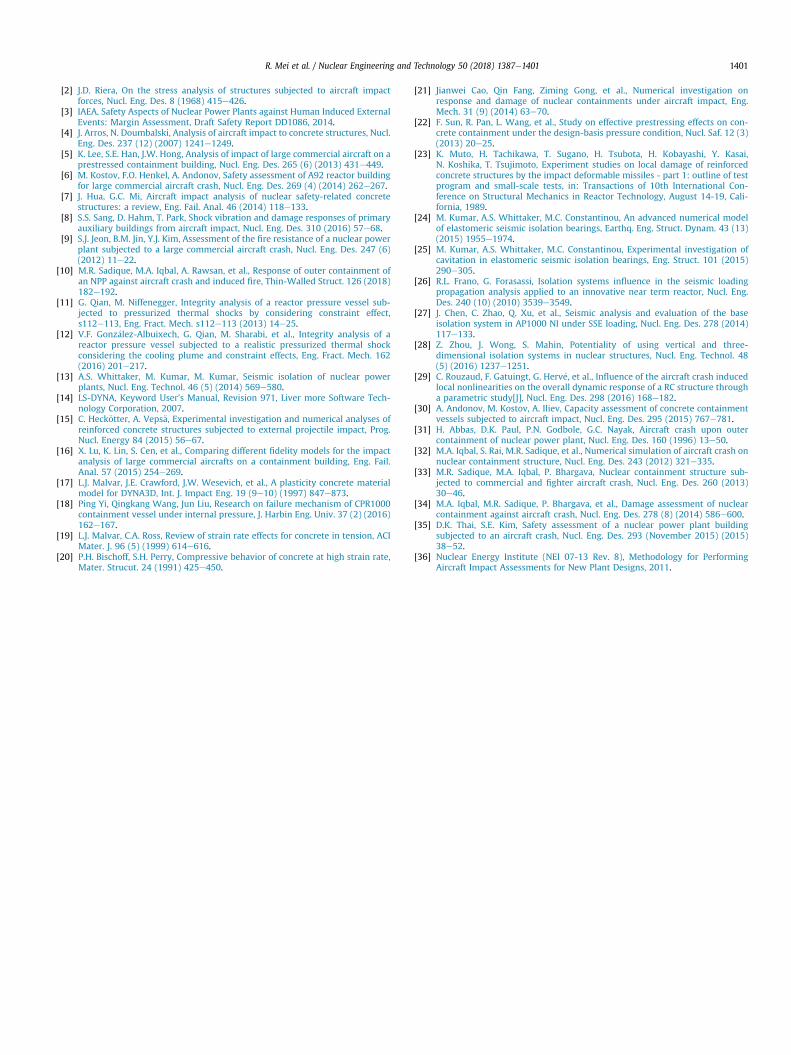
From Fig. 23, before the 50 Hz frequency for the different AIloads, there is little difference between the acceleration responsespectra for the center node of the impact location among thedifferent cases. In the high-frequency region (frequencies largerthan 50 Hz), there are variations in the acceleration responsespectra. Considering the results of Fig. 23, the peaks of the accel-eration time history from case 1 through case 7 are near 450 m/s2
under the F4 load, 100 m/s2 under the A320 load, and 150 m/s2
under the 707-320 load, and therefore, the largest accelerationresponse occurs under the F4 load. Thus, a small fighter jet with ahigh impact speed, like the F4, is capable of producing very large
Fig. 23. The X acceleration spectra for the center node of the impact location under each of the AI loads for the whole process: (a) F4, (b) A320, and (c) 707-320.
R. Mei et al. / Nuclear Engineering and Technology 50 (2018) 1387e14011398

instantaneous impact acceleration near the impact location.Fig. 24 shows the X acceleration spectra for the central node of
the impact location under different AI loads for the vibrationattenuation process. It can be found that the acceleration spectrumvaries for different AI loads. For the F4 load, there is little differencein the acceleration response spectrum at frequencies lower than20 Hz, while there is a large difference after 20 Hz. For the A320load, the peak value is between 1 Hz and 2 Hz for case 4 throughcase 6. There is a peak for all cases at approximately 4 Hz, and case 7has the greatest peak value among all the cases. For the 707-320load, the differences between the cases are not clear. Furthermore,the acceleration response for this process is smaller than that of thewhole process.
Because the basemat is located far away from the center node ofthe impact location, the acceleration response for the whole anal-ysis period is analyzed. Fig. 25 shows the X acceleration spectra ofthe base-mat location under different AI loads. Compared with theresults of the center node of the impact location, the accelerationresponse of the base mat varies among the different cases. Underthe different AI loads, there are some peak acceleration responsespectrum values near specific frequencies. For the F4 load, there are
notable peaks near 1.5 Hz, 4 Hz,15 Hz, and 45 Hz. For the A320 load,there are peaks near 1.5 Hz, 4 Hz, and 10 Hz. For the 707-320 load,there are clear peaks near 1.5 Hz, 4 Hz, 10 Hz, and 40 Hz. Themaximum peak values of the acceleration response spectrum forcase 1 through case 3 appear near 45 Hz, and the maximum peakvalues for case 4 to case 6 appear near 15 Hz. The peaks of theacceleration time history for case 1 through case 6 are similar:approximately 8 m/s2 under the F4 load, 4 m/s2 under the A320load, and 4 m/s2 under the 707-320 load.
In Fig. 25, the X acceleration response spectrum of case 6 underthe action of the El Centro seismic wave is considered. There is aclear difference between the acceleration response spectra of thestructures under the earthquake load and those of the AI load. Thefrequency bandwidth of the acceleration response spectrum islarger for the AI load than that for the earthquake load. Under theearthquake load, the acceleration response spectrum of the struc-ture has two peaks; one is near 4 Hz, and the other is near 10 Hz. Forsome aircraft loads, such as the F4 load, the high-frequencycomponent of the acceleration response spectrum is notablyhigher than that under the earthquake load. The sensitivities of thedifferent internal devices and instruments to the acceleration
Fig. 24. The X acceleration spectra of the impact location central node under the impact of each aircraft load during the vibration attenuation process: (a) F4, (b) A320, and (c) 707-320.
R. Mei et al. / Nuclear Engineering and Technology 50 (2018) 1387e1401 1399

response in the different frequency regions vary; therefore, for thevibration safety of the equipment and instruments, the effects ofthe different loads require consideration.
5. Conclusions
The dynamic characteristics of base-isolated structures underdifferent AI loads are analyzed for the CPR1000 NPP and are sum-marized in detail. The conclusions are as follows:
1. The flexible isolation layer between the base-mat and thefoundation weakens the constraint function of the foundationon the superstructure. This can effectively reduce the seismicresponse of the superstructure. But under the AI loads, therewillbe adverse effects. Under a sufficiently large AI, the isolationbearings will cause considerable horizontal deformation. Inserious cases, it can cause structural instability. In addition, theisolation bearing with different horizontal stiffness coefficienthas obvious influence on the vibration response of the base-mat,such as the frequency component and the amplitude of the vi-bration response.
2. Under different AI loads, due to the short duration of AI load, theplastic strain area distribution of the containment is mainlydistributed in the region local to the impact location. The
presence of an isolation system will not significantly affect thedistribution of the containment plastic strain area.
3. The impact loads produced by different tonnage aircraft underdifferent impact velocities have their own characteristics. Giventhe same isolation conditions, the displacement and accelera-tion responses of the containment vary owing to the differentcharacteristics produced by the different AI loads.
Acknowledgments
This research was supported by Grant 2016YFB0201000 fromNational Major Scientific Research Program of China, Grant51421064 from the National Natural Science Foundation of China,DUT17LK16 from the Fundamental Research Funds for the CentralUniversities, and Grant 51409074 from the National Natural ScienceFoundation of China.
Appendix A. Supplementary data
Supplementary data related to this article can be found athttps://doi.org/10.1016/j.net.2018.08.003.
References
[1] 10CFR50.150, Aircraft Impact Assessment, 2009.
Fig. 25. Comparison of the acceleration spectra of the base-mat center node between the earthquake load and various AI loads: (a) F4, (b) A320, and (c) 707-320.
R. Mei et al. / Nuclear Engineering and Technology 50 (2018) 1387e14011400
[2] J.D. Riera, On the stress analysis of structures subjected to aircraft impactforces, Nucl. Eng. Des. 8 (1968) 415e426.
[3] IAEA, Safety Aspects of Nuclear Power Plants against Human Induced ExternalEvents: Margin Assessment, Draft Safety Report DD1086, 2014.
[4] J. Arros, N. Doumbalski, Analysis of aircraft impact to concrete structures, Nucl.Eng. Des. 237 (12) (2007) 1241e1249.
[5] K. Lee, S.E. Han, J.W. Hong, Analysis of impact of large commercial aircraft on aprestressed containment building, Nucl. Eng. Des. 265 (6) (2013) 431e449.
[6] M. Kostov, F.O. Henkel, A. Andonov, Safety assessment of A92 reactor buildingfor large commercial aircraft crash, Nucl. Eng. Des. 269 (4) (2014) 262e267.
[7] J. Hua, G.C. Mi, Aircraft impact analysis of nuclear safety-related concretestructures: a review, Eng. Fail. Anal. 46 (2014) 118e133.
[8] S.S. Sang, D. Hahm, T. Park, Shock vibration and damage responses of primaryauxiliary buildings from aircraft impact, Nucl. Eng. Des. 310 (2016) 57e68.
[9] S.J. Jeon, B.M. Jin, Y.J. Kim, Assessment of the fire resistance of a nuclear powerplant subjected to a large commercial aircraft crash, Nucl. Eng. Des. 247 (6)(2012) 11e22.
[10] M.R. Sadique, M.A. Iqbal, A. Rawsan, et al., Response of outer containment ofan NPP against aircraft crash and induced fire, Thin-Walled Struct. 126 (2018)182e192.
[11] G. Qian, M. Niffenegger, Integrity analysis of a reactor pressure vessel sub-jected to pressurized thermal shocks by considering constraint effect,s112e113, Eng. Fract. Mech. s112e113 (2013) 14e25.
[12] V.F. Gonz�alez-Albuixech, G. Qian, M. Sharabi, et al., Integrity analysis of areactor pressure vessel subjected to a realistic pressurized thermal shockconsidering the cooling plume and constraint effects, Eng. Fract. Mech. 162(2016) 201e217.
[13] A.S. Whittaker, M. Kumar, M. Kumar, Seismic isolation of nuclear powerplants, Nucl. Eng. Technol. 46 (5) (2014) 569e580.
[14] LS-DYNA, Keyword User's Manual, Revision 971, Liver more Software Tech-nology Corporation, 2007.
[15] C. Heck€otter, A. Veps€a, Experimental investigation and numerical analyses ofreinforced concrete structures subjected to external projectile impact, Prog.Nucl. Energy 84 (2015) 56e67.
[16] X. Lu, K. Lin, S. Cen, et al., Comparing different fidelity models for the impactanalysis of large commercial aircrafts on a containment building, Eng. Fail.Anal. 57 (2015) 254e269.
[17] L.J. Malvar, J.E. Crawford, J.W. Wesevich, et al., A plasticity concrete materialmodel for DYNA3D, Int. J. Impact Eng. 19 (9e10) (1997) 847e873.
[18] Ping Yi, Qingkang Wang, Jun Liu, Research on failure mechanism of CPR1000containment vessel under internal pressure, J. Harbin Eng. Univ. 37 (2) (2016)162e167.
[19] L.J. Malvar, C.A. Ross, Review of strain rate effects for concrete in tension, ACIMater. J. 96 (5) (1999) 614e616.
[20] P.H. Bischoff, S.H. Perry, Compressive behavior of concrete at high strain rate,Mater. Strucut. 24 (1991) 425e450.
[21] Jianwei Cao, Qin Fang, Ziming Gong, et al., Numerical investigation onresponse and damage of nuclear containments under aircraft impact, Eng.Mech. 31 (9) (2014) 63e70.
[22] F. Sun, R. Pan, L. Wang, et al., Study on effective prestressing effects on con-crete containment under the design-basis pressure condition, Nucl. Saf. 12 (3)(2013) 20e25.
[23] K. Muto, H. Tachikawa, T. Sugano, H. Tsubota, H. Kobayashi, Y. Kasai,N. Koshika, T. Tsujimoto, Experiment studies on local damage of reinforcedconcrete structures by the impact deformable missiles - part 1: outline of testprogram and small-scale tests, in: Transactions of 10th International Con-ference on Structural Mechanics in Reactor Technology, August 14-19, Cali-fornia, 1989.
[24] M. Kumar, A.S. Whittaker, M.C. Constantinou, An advanced numerical modelof elastomeric seismic isolation bearings, Earthq. Eng. Struct. Dynam. 43 (13)(2015) 1955e1974.
[25] M. Kumar, A.S. Whittaker, M.C. Constantinou, Experimental investigation ofcavitation in elastomeric seismic isolation bearings, Eng. Struct. 101 (2015)290e305.
[26] R.L. Frano, G. Forasassi, Isolation systems influence in the seismic loadingpropagation analysis applied to an innovative near term reactor, Nucl. Eng.Des. 240 (10) (2010) 3539e3549.
[27] J. Chen, C. Zhao, Q. Xu, et al., Seismic analysis and evaluation of the baseisolation system in AP1000 NI under SSE loading, Nucl. Eng. Des. 278 (2014)117e133.
[28] Z. Zhou, J. Wong, S. Mahin, Potentiality of using vertical and three-dimensional isolation systems in nuclear structures, Nucl. Eng. Technol. 48(5) (2016) 1237e1251.
[29] C. Rouzaud, F. Gatuingt, G. Herv�e, et al., Influence of the aircraft crash inducedlocal nonlinearities on the overall dynamic response of a RC structure througha parametric study[J], Nucl. Eng. Des. 298 (2016) 168e182.
[30] A. Andonov, M. Kostov, A. Iliev, Capacity assessment of concrete containmentvessels subjected to aircraft impact, Nucl. Eng. Des. 295 (2015) 767e781.
[31] H. Abbas, D.K. Paul, P.N. Godbole, G.C. Nayak, Aircraft crash upon outercontainment of nuclear power plant, Nucl. Eng. Des. 160 (1996) 13e50.
[32] M.A. Iqbal, S. Rai, M.R. Sadique, et al., Numerical simulation of aircraft crash onnuclear containment structure, Nucl. Eng. Des. 243 (2012) 321e335.
[33] M.R. Sadique, M.A. Iqbal, P. Bhargava, Nuclear containment structure sub-jected to commercial and fighter aircraft crash, Nucl. Eng. Des. 260 (2013)30e46.
[34] M.A. Iqbal, M.R. Sadique, P. Bhargava, et al., Damage assessment of nuclearcontainment against aircraft crash, Nucl. Eng. Des. 278 (8) (2014) 586e600.
[35] D.K. Thai, S.E. Kim, Safety assessment of a nuclear power plant buildingsubjected to an aircraft crash, Nucl. Eng. Des. 293 (November 2015) (2015)38e52.
[36] Nuclear Energy Institute (NEI 07-13 Rev. 8), Methodology for PerformingAircraft Impact Assessments for New Plant Designs, 2011.
R. Mei et al. / Nuclear Engineering and Technology 50 (2018) 1387e1401 1401


![SEISMIC ROOF ISOLATION OF HALKAPINAR … · most efficient seismic isolation solution for the Halkapınar Gymnasium. In this thesis, theory of seismic isolation, ... [18] (From AASHTO](https://img.pdfslide.us/doc/110x75/5b5ba6ce7f8b9a905c8e7903/seismic-roof-isolation-of-halkapinar-most-efficient-seismic-isolation-solution.jpg)