Embed Size (px)
Citation preview

University of Central Florida University of Central Florida
STARS STARS
Retrospective Theses and Dissertations
1976
Dynamic and Stability Characteristics of an Articulated Frame Dynamic and Stability Characteristics of an Articulated Frame
Railway Passenger Truck Railway Passenger Truck
David Kenneth Platner University of Central Florida
Part of the Engineering Commons
Find similar works at: https://stars.library.ucf.edu/rtd
University of Central Florida Libraries http://library.ucf.edu
This Masters Thesis (Open Access) is brought to you for free and open access by STARS. It has been accepted for
inclusion in Retrospective Theses and Dissertations by an authorized administrator of STARS. For more information,
please contact [email protected].
STARS Citation STARS Citation Platner, David Kenneth, "Dynamic and Stability Characteristics of an Articulated Frame Railway Passenger Truck" (1976). Retrospective Theses and Dissertations. 249. https://stars.library.ucf.edu/rtd/249

DYNk~IC AND STABILITY CHARACTERISTICS OF AN ARTICULATED FRAME RAILWAY PASSENGER TRUCK
BY
DAVID KENNETH PLATNER B.S.A.E., TriState University, 1969
THESIS
Submitted in partial fulfillment of the requirements for the degree of Master of Sciance in the
Graduate Studies Program of the College of Engineering of
Florida Technological University
Orlando, Florida 1976

DYNAMIC AND STABILITY CHARACTERISTICS OF AN ARTICULATED FRAME RAILWAY PASSENGER TRUCK
by
David Kenneth Platner
ABSTRACT
Mass transit vehicles in normal rail service
frequently attain speeds which can excite carbody oscil-
lations (primary hunting), as well as sustained lateral
oscillations of the trucks (secondary hunting) . The
carbody mo·tions have been shown to generate passenger
discomfort and sustained truck hunting can lead to de-
railment. This thesis developes approximate equations
which predict the carbody hunting frequencies, as well
as the hunting speed of an articulated frame truck. The
linear equations of motion are derived from a simplified
model of a railway vehicle. A comparison indicates the
the results obtained using the approximate truck hunting
equation presented here are within ten percent of the re
sults obtained from more rigorous approaches reported by
others.

CONTENTS
NOTATION -.- . . . . . . . . . . . . . . . . . . . Chapter
I. INTRODUCTION . . . . . . . . . . . . . . . II. THE MATH MODEL . . . . . . . . . . . . . .
Vertical Natural Frequency
Roll Natural Frequency
Hunting Speed • • •
. . . . . . .
. . . . . . .
. . . . . . .
iii
iv
1
8
11
13
17
III. THE NUMERIC MODEL AND PARAMETERIC STUDY • . 21
IV. DISCUSSION OF RESULTS •
V. CONCLUSIONS . . . . . . . . . . . . . . APPENDIX . . . . . . . . . REFERENCES . . . . . . . . . . . . . . . . .
25
37
38
42

NOTATION
B = Car Roll Angle (rad)
~ = Wheel Coning Ratio (in/in)
9 = Truck Yaw Angle (rad)
2a = Track Gauge (in)
A = Total Transverse Damping Parameter (lb)
2b = Truck Wheel Base (in)
B = Total Yaw Damping Parameter (lb-in2jrad)
d = Wheel Diameter (in)
De = Truck Yaw Damping Canst. (lb-in-sec2jrad)
DL = Truck Longitudinal Damping Canst. (lb-sec/in)
Dv = Truck Vertical Damping Const. (lb-sec/in)
Dy - Truck Transverse Damping Canst. (lb-sec/in)
f = Vertical Natural Frequency (Hertz)
fd = Damped Vertical Natural Frequency (Hertz)
fr
F
g
=
-
= Roll Natural Frequency (Hertz)
Friction Force Coefficient (lb)
Acceleration of Gravity (in/sec2)
Distance from Lateral Spring to Car C.G. (in)
i - Unit Vector in Longitudinal Direction
h =
Ic - Car Moment of Inertia in Roll (lb-in-sec2jrad)
It = Truck Moment of Inertia in Yaw (lb-in-sec2/rad)
) = Unit Vector in Transverse Direction
iv

Ke = Truck Yaw Stiffness (lb-in/rad)
KL = Truck Longitudinal Stiffness (lb/in)
Kv = Truck Vertical Stiffness (lb/in)
Ky = Truck Transverse Stiffness (lb/in)
2Ls = Truck Vertical Spring Spacing (in)
Me = Car Mass (lb-sec2/in)
Mt - Truck Mass (lb-sec2/in)
- - -P1, P2 , P3, P 4 = Force Vectors at Wheel-Rail (lb)
r = Wheel Radius (in)
ra = Distance from Roll Center to Lateral Spring (in)
R = Distance from Roll Center to Car C.G. (in)
V = Truck Forward Velocity (mph)
Wa - Weight on Truck Axle (lb)
We = Car Weight (lb)
Wt = Truck Weight(lb)
y = Truck Transverse Displacement (in)
z = Car Vertical Displacement (in)
v

1
INTRODUCTION
Mass transit vehicles such as those in service on
the New York subway system encounter a wide range of oper
ating conditions. The speed can vary between fifteen
miles per hour in curves to eighty miles per hour on
straight track. Acceleration, braking, varying passenger
load, and varying track bed flexibility all contribute to
the complex rail vehicle environment. This paper will be
restricted to the analysis of the rail vehicle suspension
of an articulated frame truck which is considered to be
running under steady state conditions on a straight,
level, and rigid track. Additional assumptions will be
interjected as they pertain to the topic being discussed.
A concise list of assumptions is presented later.
The rail vehicle suspension is defined as the
complete assembly, as shown in Photograph 1, whose
components are the wheels, axles, motors, truck frame,
bolster, primary suspension, and the secondary suspension.
The primary suspension is defined as the elastic compo
nents connecting the axles to the truck frame, and the
secondary suspension is defined as the elastic components
connecting the carbody to the truck.

2
Photo 1 Complete Truck Ass~~ly

3
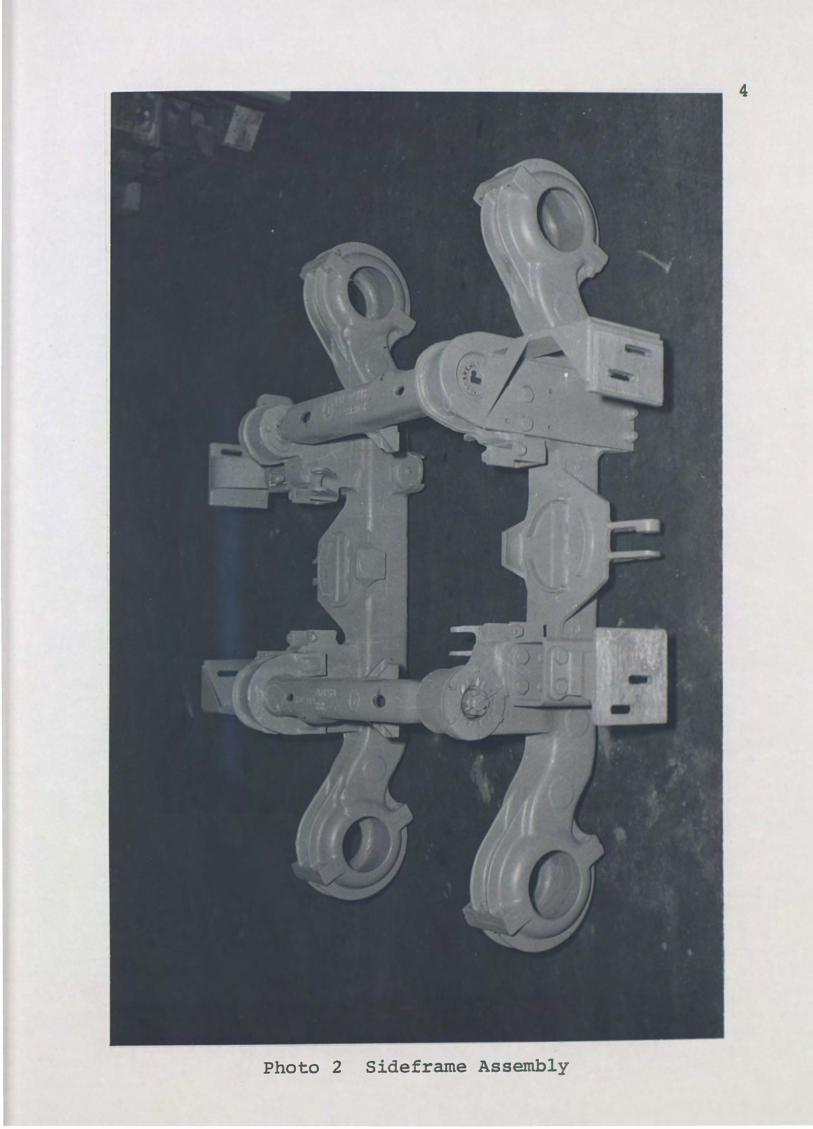
An articulated frame truck, as shown in Photo
graph #2, has two distinct sidefrarnes. Each sidefrarne
is attached to the other through a hinging mechanism
which allows sideframe rotation about the hinge line.
This characteristic allows each wheel to move vertically
over track irregularities independent of the primary
suspension rate. Articulation thus allows the compo
nents at the primary to be relatively stiff (about
100,000 pounds per inch) in comparison to the secondary
suspension (about 2,000 pounds per inch). In this paper,
the primary suspension will be considered rigid.
Another major type of truck in mass transit use
in the United States is the rigid frame truck. The
sideframes of this truck are a single unit and do not
articulate. The rigid frame truck permits vertical
wheel motion through a soft primary suspension (approxi
mately 15,000 pounds per inch). The difference in the
stiffness of the primary suspension is the major item
that distinguishes an articulated frame from a rigid
frame truck. A rigid primary can only be accommodated
by an articulated frame truck and thus consideration of
the rigid frame truck is omitted from this analysis.
4
Photo 2 Sideframe Assembly

5
A survey by Law and Cooperrider (1974) has
established the basic criteria for investigations of the
rail vehicle system. Of primary concern are the oscilla
tions of the transit vehicle allowed by the suspension
elements. The survey mentioned above divides the harmonic
oscillations (also called hunting) into two categories:
primary hunting and secondary hunting. Primary hunting
refers to the harmonic motions of the carbody and second
ary hunting to the truck motions. Of the possible motions
defined for the total system, only the following will be
investigated here. The first is the vertical bounce of
the carbody. The second is the combined roll and lateral
oscillation of the carbody. The third and final motion
considered here describes the lateral truck hunting.
The carbody bounce and roll are defined as reso
nant conditions (Cooperrider 1968). The dynamic equations
describing these two motions will be developed in a later
section. These resonant frequencies are usually found to
be less than two Hertz and are low speed (less than twenty
miles per hour) characteristics. The amplitudes of the
bounce and roll oscillations have been found to be ade
quately controlled by damping (Diboll and Bieniecki 1968).
6
The lateral truck hunting, however, is found to
be an instability phenomenon. The truck hunting is ini
tiated only above a certain critical speed and is char
acterized by violent truck lateral motions. Unlike a
resonant condition which is critical at distinct fre
quencies, the amplitude of truck hunting oscillations
will continue to build as the velocity is increased
above the critical speed. The hunting amplitude will
usually be limited by the flanges of the wheels, but
can lead to derailment.
Truck hunting is generated by the tapered wheel
profile commonly in use to aid in curve negotiation. A
cylindrical tread theoretically does not hunt, but it
also generates excessive flange wear. Wickens (1966)
repoxts that even a cylindrical tread profile will quick
ly become worn to a measurable taper, which will then
generate hunting. Wickens (1965) has also investigated
the wheel profile characteristics. His article and an
article by Law and Brand (1973) indicate that the true
nature of the wheel rail interface is a nonlinear one
which can significantly influence the hunting speed of a
wheel set. However, Wickens (1966) states that the non
linear effects are minimal for paired wheel sets as used
in a truck. For practical use in this thesis, only
tapered wheels and linear forces will be used.

A few articles have presented techniques to
determine the critical speed. Cooperrider (1968) em
lays a digital computer technique, which plots the root
loci of the characteristic equations. Law and Brand
(1973) achieve their solution of nonlinear equations
with the aid of CSMP (Continuous Systems Modeling
Program). Clark and Law (1967) and also Vernon (1967)
have presented approximate methods which can be used to
determine the hunting speed. The approximation pre
sented by Clark and Law (1967) is used in this thesis
and further discussed in the next section. A compari
son of the approximate results with those using a more
rigorous approach is also presented later.
7
This thesis incorporates the approximate equa
tions into a computer program which is designed for a
timesharing or interactive system. The natural fre
quencies and critical speed are computed after entering
data pertaining to truck geometry, spring rates, and
damping constants. A table is also included to indicate
how changes made to the input data will influence the
calculated data.

8
THE MATH MODEL
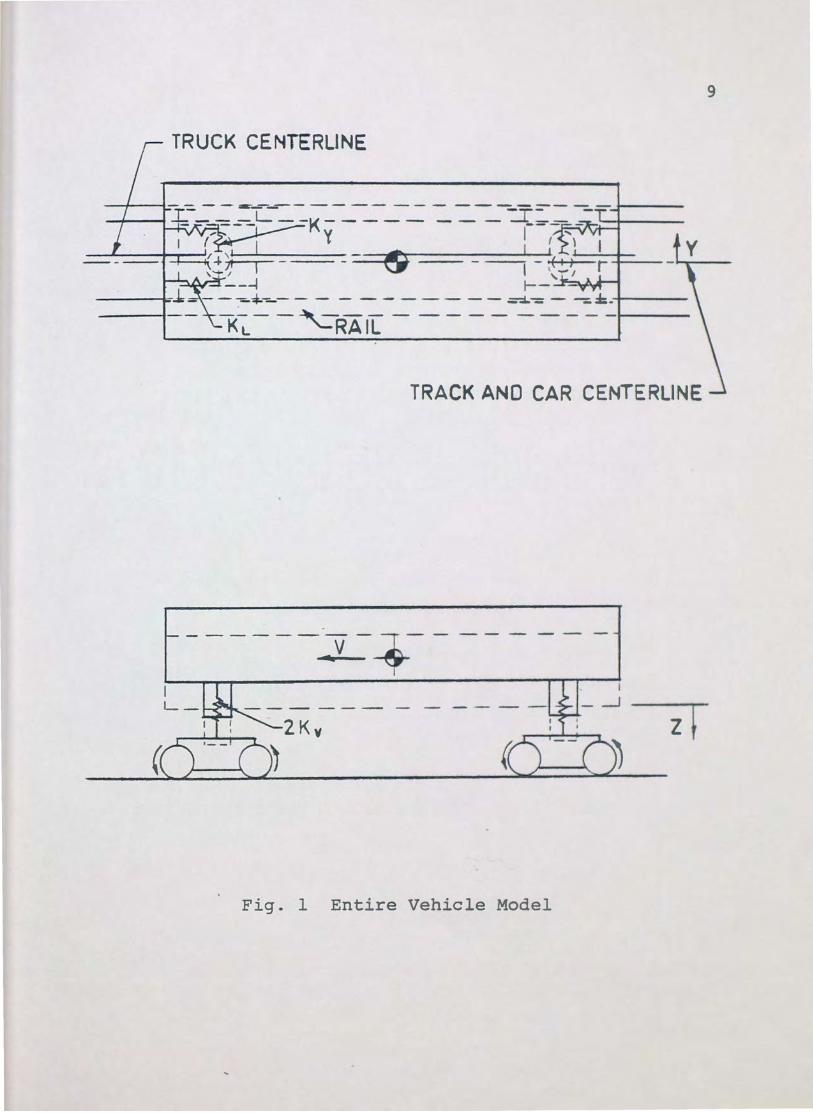
Figure 1 depicts the model of the general railway
vehicle. It consists of a rigid carbody supported elas
tically by the secondary suspension. The trucks are
rigidly restrained to move longitudinally with the car
body and elastically restrained vertically and laterally
to allow relative motion between the carbody and the
trucks. The vertical springs of the secondary suspen
sion are either air bellows or coil springs as shown in
Photograph 1. The vertical spring rate Kv and the lat
eral spring rate Ky are defined by these secondary sus
pension elements. The damping Dv and Dy are supplied by
vertical and lateral shock absorbers, which can also be
seen in Photograph 1. Rotation of the trucks beneath
the carbody is elastically restrained by sidebearers,
which provide the values for KL and DL·
The following assumptions have also been made in
order to develop the equations of motion. The vehicle
is operating on straight and level track (tangent track).
All vehicle and truck components are considered rigid.
The truck frame is articulated and mounted to the axle
through a rigid primary suspension. The axles are free
running, and no tractive, braking, or frictional forces
9
TRUCK CENTERLINE
TRACK AND CAR CENTERLINE
------~v- ~--- -------4 ~
z
Fig. 1 Entire Vehicle Model

10
are considered. Aerodynamic forces are also excluded.
External forcing functions due to rail joints and wheel
flats are considered only as possible exciters of reso
nant frequencies. The equations are linear, small de
flections and rotations are assumed, and only the steady
state solution is considered. The wheel tread profile is
approximated by a conical taper.
Cooperrider (1968) has presented the equations of
motion for a seven degree of freedom vehicle. This
thesis, however, is only concerned with the vertical
bounce of the carbody, the lateral roll of the carbody,
and the truck lateral hunting. Cooperrider (1968) does
not include the carbody vertical bounce in his seven
degree of freedom model. However, Diboll and Bieniecki
(1968) state that no coupling exists between the verti
cal bounce and the lateral motions of the carbody or the
trucks. Also, the roll natural frequency is not influ
enced by the truck hunting. Cooperrider (1968) and Clark
and Law (1967) uncouple the carbody motions from the
truck hunting equation. The influence of coupling on the
hunting speed will be discussed later. The following
sections will develop the uncoupled equations of motion
individually.

11
Vertical Natural Frequency
The vertical natural frequency can be determined
with the ~~lp of F~gure 2. The motion is pure vertical
bounce. The truck is assumed to act as a rigid support,
which eliminates the influence of the rail deflections.
Applying Newton's Law, the equation of motion is
Mcz+4Dvz+4Kvz=O. (1)
Here, Me is the total car mass, Kv is the vertical spring
rate, and Dv is the vertical damping constant. It can
be shown from Equation 1 that the damped natural fre
quency, fd, is
(2)
Diboll and Bieniecki (1968) indicate that the damping for
optimum passenger comfort is about thirty percent of cri
tical. For the system above, setting Dv equal to .3JKvMc
results in the following equation fbr fd:
fd = .3036/[ . (3)
Since this is only a five percent reduction from the un
damped natural frequency, f, it is permissible in practi
cal design applications to use
f=;~.

- . -
2Dv
,----1
-----, ,--------1 I
2
Fig. 2 Vertical Model
12
z
13
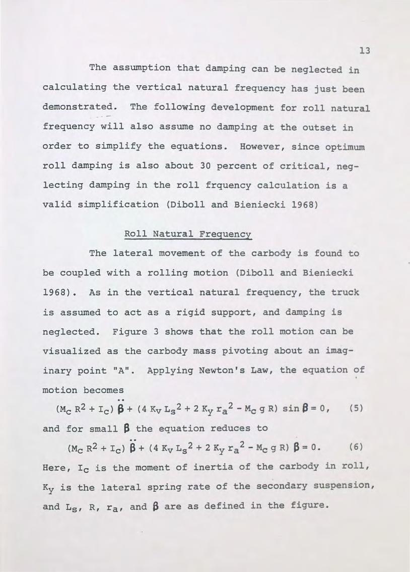
The assumption that damping can be neglected in
calculating the vertical natural frequency has just been
demonstrated. The following development for roll natural ---
frequency will also assume no damping at the outset in
order to simplify the equations. However, since optimum
roll damping is also about 30 percent of critical, neg
lecting damping in the roll frquency calculation is a
valid simplification (Diboll and Bieniecki 1968)
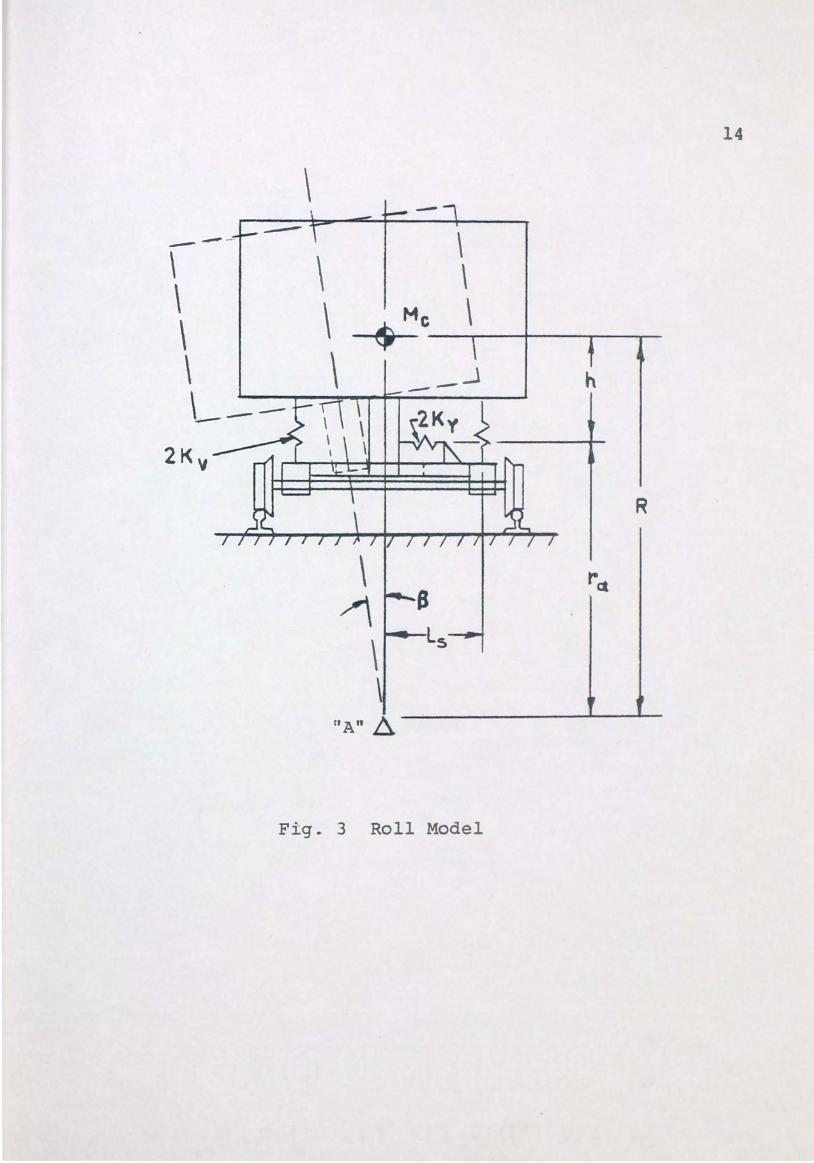
Roll Natural Frequency
The lateral movement of the carbody is found to
be coupled with a rolling motion (Diboll and Bieniecki
1968). As in the vertical natural frequency, the truck
is assumed to act as a rigid support, and damping is
neglected. Figure 3 shows that the roll motion can be
visualized as the carbody mass pivoting about an imag-
inary point "A". Applying Newton's Law, the equation of
motion becomes
(McR2+Ic) ~+ (4KvL5 2+2Kyra2 -McgR) sinf3=0, (5)
and for small a the equation reduces to
(Me R2 + Ic) jj + (4 Kv L 5 2 + 2 Ky ra2 - Meg R) P = 0. (6)
Here, Ic is the moment of inertia of the carbody in roll,
Ky is the lateral spring rate of the secondary suspension,
and L5 , R, ra, and 8 are as defined in the figure.
\
\ \ \ \
\ \ $ M c_\....----+-------.......---\ \ h
L--
R
\ ret
~ Ls
\ \
nAn ~
Fig. 3 Roll Model
14

From Equation 6, the roll natural frequency can
be shown to be
15
. _. - fr = l_ J 4 Kv Ls2 + 2 Ky ra2- Meg R 2ir McR2+Ic
(7)
In order to determine the distance to the roll
center, R, consider the static condition generated by a
force, F, applied laterally at the carbody e.G. The
summation of forces can be shown to be
2 Ky Fa a - F- Meg 6 = 0,
and the moment about "A" can be shown to be
2 Ky r a 2 8 + 4 Kv Ls 2 fl - F R - Me g R 8 = 0 •
Combining Equations 8 and 9, the distance to the roll
center becomes
R = 2 Kv Ls2 + Ky h2 Kyh
where, h is given by
h = R- ra •
'
(8)
(9)
(10)
(11)
The roll frequency equation is descriptive of a
secondary system with independent springs providing the
vertical rate Kv· However, the secondary suspension of
most new rapid transit trucks is an a·ir spring. The
height of the air spring is controlled by a level valve
which maintains the floor of the car at a constant height,
independent of the number of passengers being carried.

16
Most transit cars do not have a separate level valve for
each air spring. If only one level valve is used on a
truck, the air springs are interconnected and allow air -.-
to flow freely from one spring to the other as the car-
body rotates. The rotation compresses one spring and
extends the other. The resistance that remains will be
called the roll vertical spring rate.
The two level valve car has one level valve
centered on each truck, and the vertical spring rate is
replaced by the roll vertical spring rate for roll fre-
quency calculations. A three level valve system has a
centered level valve on one truck and independent level
valves on the other. On a three level valve system, an
average of the roll rate and the vertical spring rate
is used for Kv. A four level valve system has indepen
dent level valves and the roll equations use the vertical
spring rate. The independent air spring is assumed to
generate the same rate in roll as it does in vertical
bounce. The equation for hunting speed developed in the
following section will be shown to be independent of the
vertical spring rate.
17
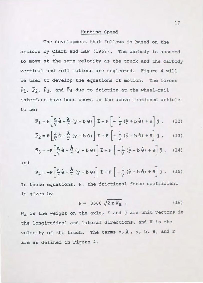
Hunting Speed
The development that follows is based on the
article by Clark and Law (1967). The carbody is assumed -.-
to move at the same velocity as the truck and the carbody
vertical and roll motions are neglected. Figure 4 will
be used to develop the equations of motion. The forces
P1, P2, P3, and P4 due to friction at the wheel-rail
interface have been shown in the above mentioned article
to be:
(12)
- [a · A J [ 1 · · 1 P2=F V9+r (y-b9) I+F - V (y-b9) +9j j, (13)
- [a · A J - [ 1 · · J ... P3 = -F v e + r (y- b 9) ~ + F - v (y- b 9) + e J , (14)
and
- [a· A J.. [ 1 · · l-P4=-F re+r (y+b9) 1.+F -v (y+b9) +9J J. (15)
In these equations, F, the frictional force coefficient
is given by
F = 3500 j2 r Wa • (16)
Wa is the weight on the axle, i and j are unit vectors in
the longitudinal and lateral directions, and V is the
velocity of the truck. The terms a,~, y, b, 9, and r
are as defined in Figure 4.

18
--\\ \ ----t-+---+-~--1-----L +-=--.::.::_::_j-+--_j
\
I \
\
~~~~~~~~~~-+ I I
\ .
\ b i I \
~ I ~ ~-+--l--1
I ~1 I I I I
\ -..-!
/- ..,-......... .., -- "--
'-CAR OUTL\NE TRACK CENTERL\NE.
iRUCK CE.NTERLl t'•E
Fig. 4 Hunting Model

19
The summation of lateral forces at the wheel-rail
interface is given by
- - -[
1 -· ] F y = -4 F v y - 9 I (17)
and the moment about the origin is
(18)
Applying Newton's Law, the equations of motion are
.. 1 . Mt y + v (4 F + v Dy) y + Ky y- 4 F 9 = 0 I (19)
and
Where, Mt is the truck mass, It is the truck moment of
inertia in yaw, Ky is the lateral spring rate, Dy is the
lateral damping constant, Kg is the yaw spring rate, and
n9 is the yaw damping constant. It can be noted that Kv'
the vertical spring rate, does not appear in the above
equations. Ke and o9 are defined by
(21)
and
(22)

20
After a Laplace transformation, the characteristic
equation takes the form
s4 + (A It+ B Mt) s3· + (Ke Mt + Ky It + Mt It V Mt It
A B ) s2 Mt It v2
where s is the Laplace transform variable. After applying
a neutral stability criteria to the above equation (Clark
and Law 1967) , the equation for the critical hunting speed
can be shown to be
V 2 = A B (A It+ B Mt) (A Ke + B Ky) r c (A It+ B Mt) 16 a A F2 -A B r (Mt Ke- It Ky) 2 '
where the total transverse damping parameter, A, is
A= 4 F + V Dy,
and the total yaw damping parameter, B, is
B=4F (a2+b2) +VDe.
The critical speed, Vc, is the speed at which
truck hunting can start. Further increase above this
(24)
(25}
(26}
speed results in sustained lateral oscillations which will
eventually cause distruction of the wheel flanges and
derailment of the truck. Thus, the critical speed repre-
sents an upper limit to the operating speed of the ve
hicle. Equation 24, for the critical velocity, is
nonlinear since both the A and B terms contain velocity.
The following section will present the method used to
solve for the critical hunting speed.

21
THE NUMERIC MODEL AND PARAMETRIC STUDY
The· equations developed in the previous section
have been assembled into a computer program. The program
is written in Basic language and designed for a time
sharing or interactive computing system. The program
listing is presented in the Appendix. The ability to use
the time sharing mode allows the program to be conversa
tional. In other words, the computer prompts the user
for a response with questions. In the program for this
thesis, the user enters data pertaining to truck geom
etry, spring rates, and damping constants. The computer
then prints out a table of all the input parameters fol
lowed by the calculated values of the vertical natural
frequency, the roll natural frequency, and the hunting
speed. The program also allows the user to change all or
any portion df the input data. A typical design example
is presented later.
Equations 4 and 7 for vertical frequency and roll
frequency generate specific values. However, as stated
earlier, the hunting equation is nonlinear and must be
solved through an iterative process. Only when the esti
mated critical velocity used on the right hand side of
Equation 24 matches the calculated velocity is the iter-
ative process complete.
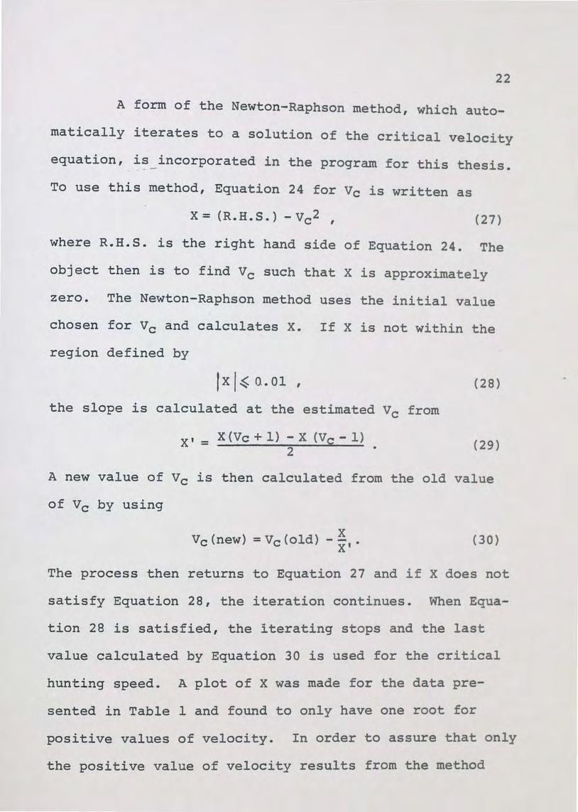
22
A form of the Newton-Raphson method, which auto
matically iterates to a solution of the critical velocity
equation, i~_incorporated in the program for this thesis.
To use this method, Equation 24 for Vc is written as
X= (R. H. S.) - V c2 , ( 27)
where R.H.S. is the right hand side of Equation 24. The
object then is to find Vc such that X is approximately
zero. The Newton-Raphson method uses the initial value
chosen for Vc and calculates X. If X is not within the
region defined by
r x 1 ~ o.. 01 , ( 28)
the slope is calculated at the estimated Vc from
X,= x·(Vc+l) -x (V0 -l) 2 • (29)
A new value of Vc is then calculated from the old value
of Vc by using
X Vc (new) = Vc (old) -X'. (30)
The process then returns to Equation 27 and if X does not
satisfy Equation 28, the iteration continues. When Equa
tion 28 is satisfied, the iterating stops and the last
value calculated by Equation 30 is used for the critical
hunting speed. A plot of X was made for the data pre-
sented in Table 1 and found to only have one root for
positive values of velocity. In order to assure that only
the positive value of velocity results from the method

23
described above, Clark and Law (1967) recommend that the
initial value of the critical velocity for Equation 27 be
estimated from Equation 24 with zero damping. The assump--.-
tion of zero damping eliminates the effects of velocity
from the right hand side of Equation 24 and yields an
acceptable first estimate for Vc. The Newton-Raphson
method as used in this thesis has been found to converge
on a solution within five iterations.
An example of a typical lightweight truck is
shown in Table 1. The first part of the table, which is
labeled Design Data, presents the design parameters re-
quired to calculate the values of vertical natural fre-
quency, roll natural frequency, and the hunting speed.
In general, these are parameters which can be measured
by physical means. This data will be used later in the
parametric study and in the design example. The last
part of the table, which is labeled Calculated Values,
presents the numeric output from the computer program.

24
TABLE 1
DESIGN PARAMETERS AND PROGRAM CALCULATIONS FOR A TYPICAL LIGHTWEIGHT TRUCK
D·e·sign ·Data
1. Total car weight (lb)
2. Total truck weight (lb/trk)
3. Truck unsprung weight (lb/trk)
4. Radius - car mass moment (in)
5. Radius - truck mass moment (in)
6. Vertical spring spacing (in)
7. Dist. - car e.G. to lateral spg. (in)
8. Wheel diameter (in)
9. Track gauge (in)
10. Wheel base (in)
11. Coning ratio (in/in)
12. No. level valves per car (#/car)
13. Vertical spring rate (lb/in/spg)
14. Roll vert. spring rate (lb/in/spg)
15. Lateral spring rate (lb/in/trk)
16. Yaw spring rate (in-lb/rad/trk)
17. Lat. damper constant (lb-sec/in/trk)
18. Yaw damper constant (in-lb-sec/rad/trk)
Program Calculations
1. Vertical natural frequency (Hz)
2. Roll natural frequency (Hz)
3. Hunting speed (mph)
Value
71820.00
12000.00
4000.00
50.00
30.00
71.00
29.00
28.00
59.00
82.00
0.05
3
2550.00
1693.90
2066.00
529000.00
413.00
761000.00
Value
1.178
0.539
67.437
25
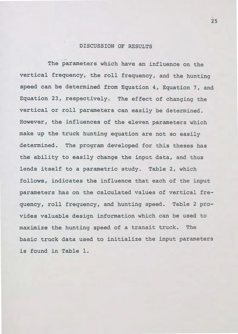
DISCUSSION OF RESULTS
--The parameters which have an influence on the
vertical frequency, the roll frequency, and the hunting
speed can be determined from Equation 4, Equation 7, and
Equation 23, respectively. The effect of changing the
vertical or roll parameters can easily be determined.
However, the influences of the eleven parameters which
make up the truck hunting equation are not so easily
determined. The program developed for this theses has
the ability to easily change the input data, and thus
lends itself to a parametric study. Table 2, which
follows, indicates the influence that each of the input
parameters has on the calculated values of vertical fre-
quency, roll frequency, and hunting speed. Table 2 pro
vides valuable design information which can be used to
maximize the hunting speed of a transit truck. The
basic truck data used to initialize the input parameters
is found in Table 1.
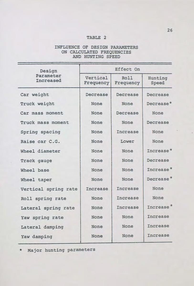
TABLE 2
INFLUENCE OF DESIGN PARAMETERS ON CALCULATED FREQUENCIES
AND HUNTING SPEED
Design Effect On Parameter Vertical Roll Increased Frequency Frequency
Car weight Decrease Decrease
Truck weight None None
Car mass moment None Decrease
Truck mass moment None None
Spring spaci~g None Increase
Raise car e.G. None Lower
Wheel diameter None None
Track gauge None None
Wheel base None None
Wheel taper None None
Vertical spring rate Increase Increase
Roll spring rate None Increase
Lateral spring rate None Increase
Yaw spring rate None None
Lateral damping None None
Yaw damping None None
* Major hunting parameters
26
Hunting Speed
Decrease
Decrease*
None
Decrease
None
None
Increase*
Decrease
Increase*
Decrease*
None
None
Increase*
Increase
Increase
Increase

27
Table 2 indicates the general effects of changing
the design parameters, but omits the magnitude of the
effect. For example, of the eleven hunting parameters
only five have a significant influence on the hunting
speed. Also, many of the parameters have maximum and/or
minimum limitations dictated by the particular railroad
or transist authority's specifications. Each of the
parameters will be examined in the following paragraphs
with emphasis on the degree of effectiveness and the
practical limitations. The data in Table 1 is used as the
base for comparisons.
The maximum car weight will always be limited by
the authority's specification. However, if the authority
.would increase the car weight by 10 percent, a 5 percent
decrease in vertical and roll frequency would result, but
less than a .2 percent decrease in hunting speed would
result. Thus car weight has little influence on the
hunting speed. The vertical and roll frequencies are the
result of the car weight, and as such, they are not used
to determine the car weight.
The maximum truck weight is very seldom limited
by the authority. The car builder, however, is restrict
ed to a maximum weight on rail, which means the lighter
the trucks the greater the number of passengers that can
be carried. An increase of 10 percent in truck weight

28
will decrease the hunting speed by over 5 percent. Thus,
truck weight has a major influence on the hunting speed,
and a reduction in truck weight is desirable. The verti
cal and roll frequencies are not influenced by the truck
weight.
The car mass moment of inertia only influences
the roll frequency. A 10 percent decrease produces a 2
percent decrease in the roll frequency. The car moment
of inertia is not a parameter which can be easily changed
and is usually dictated by the design of the car builder.
The truck mass moment of inertia is defined by
the radius of gyration. An increase of 10 percent in the
radius of gyration will decrease the hunting speed by
·about 3 percent. In general it is not practical to re
duce the radius of gyration after a truck design is es
tablished. However, in the early layout stage of a new
truck proposal the large mass items such as the motors
and sideframes can be located as close as practical to
the center of the truck. The vertical and roll frequen
cies are not influenced by the truck moment of inertia.
The lateral spring spacing and the height of the
car e.G. only influence the roll frequency. A 10 percent
increase in spring spacing will generate a 6 percent
increase in the roll frequency. Some transit systems
will specify a range for the roll frequency.

The vertical springs can be positioned on a new car to
provide the desired roll characteristics. If the dis
tance from the lateral spring to the car e.G. is
increased by 10 percent, almost a 5 percent decrease
29
in roll frequency will result. The distance to the car
e.G. is not a variable and will be determined by the de
sign of the car.
The wheel diameter will be specified by the par
ticular transit authority. If the diameter is allowed to
increase by 10 percent, the hunting speed will increase
by about 5 percent. However, the larger wheel will weigh
more and the negative influence of the heavier truck
would have to be considered. Even though the wheel diam
eter has a significant influence on the hunting speed,
restrictions by the transit authority eliminate increas
ing the wheel diameter as a means to increase the hunt
ing speed. The vertical and roll frequencies are not a
function of the wheel diameter.
The track gauge has a very small influence on the
hunting speed. If the track gauge is increased from the
59 inch standard gauge to the 69 inch wide gauge used on
the BART system in San Francisco, less than a one mile
per hour decrease in hunting speed would result. The
track gauge does not influence the vertical and roll fre-
quencies.
30
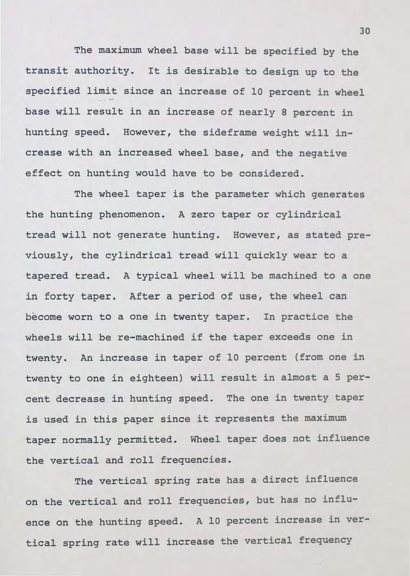
The maximum wheel base will be specified by the
transit authority. It is desirable to design up to the
specified limit since an increase of 10 percent in wheel
base will result in an increase of nearly 8 percent in
hunting speed. However, the sideframe weight will in
crease with an increased wheel base, and the negative
effect on hunting would have to be considered.
The wheel taper is the parameter which generates
the hunting phenomenon. A zero taper or cylindrical
tread will not generate hunting. However, as stated pre
viously, the cylindrical tread will quickly wear to a
tapered tread. A typical wheel will be machined to a one
in forty taper. After a period of use, the wheel can
become worn to a one in twenty taper. In practice the
wheels will be re-rnachined if the taper exceeds one in
twenty. An increase in taper of 10 percent (from one in
twenty to one in eighteen) will result in almost a 5 per
cent decrease in hunting speed. The one in twenty taper
is used in this paper since it represents the maximum
taper normally permitted. Wheel taper does not influence
the vertical and roll frequencies.
The vertical spring rate has a direct influence
on the vertical and roll frequencies, but has no intlu
ence on the hunting speed. A 10 percent increase in ver
tical spring rate will increase the vertical frequency

31
by about 5 percent and increase the roll frequency by
about 2 percent. Transit authorities will occasionally
give ranges for the vertical and roll frequencies. It is
common practice in the transit industry to design for a
vertical frequency between 1.0 to 1.2 and a roll frequen
cy between .45 to .65.
The roll spring rate is the vertical rate of the
air springs when the air supply interconnects the two air
springs. This rate is a function of the air springs de
sign and as such is not easily changed. The vertical
frequency and the hunting speed are not effected by this
characteristic.
The lateral spring rate is another parameter which
has a major influence on the hunting speed. A 10 percent
increase in the lateral spring rate will increase the
hunting speed by a~ost 5 percent. Unfortunately, the
increased lateral rate also increases the roll freque
Some transit specifications will limit the roll na
frequency which will thereby limit the lateral sp ~
rate. The vertical frequency is not influenced b
lateral spring rate.
The yaw spring rate has a stabilizing in£ e
the hunting speed, but no influence on the vert·ca_
roll frequencies. At the magnitude shown in Table
10 percent increase in the yaw spring rate only produces

32
a .5 percent increase in the hunting speed. However, at
lower values a 5 percent increase in hunting speed can
result from a 10 percent increase in the yaw spring rate.
The yaw spring rate, however, restricts the truck's abil
ity to negotiate curves and must be limited to a safe
value. The determination of this safe value is not within
the scope of this paper.
The lateral and yaw damping have little influence
on the hunting speed, and are normally defined by other
requirements. The optimum lateral damping has been given
by Diboll and Bieniecki (1968) as 30 percent of critical.
The yaw damping is determined from the physical character
istics of the side bearing component. The effect of lat
eral damping is neglected in the roll equation and has
no influence on the vertical frequency. Yaw damping has
no influence on the vertical or roll frequencies.
To summarize the above, it was determined that,
of the eleven design parameters influencing the hunting
speed, only five have a significant effect. An increase
of 10 percent in the truck weight, wheel diameter, wheel
base, wheel taper, or lateral spring rate produced about
a 5 percent change in the hunting speed. The above con
clusions are based on the initial data found in Table 1.
The ability to modify the data leads naturally into a
practical design example.

33
Starting with the data found in Table 1, one is
required to increased the hunting speed from 67 miles per
hour to at least 90 miles per hour. Of the five param
eters which significantly influence the hunting speed,
the transit authority's specification is found to define
the wheel diameter, the wheel base, and the wheel taper.
A weight study has also indicated that the truck weight
cannot be reduced more than five percent. The lateral
spring rate can be increased, but the specification also
limits the roll frequency to .65 Hertz.
Allowing .65 Hertz for the roll frequency, it is
determined that the lateral spring rate can be increased
from 2066 to 3600 pounds per inch. Also, allowing a five
hundred pound decrease in the truck weight, the calcu
lated hunting speed is found to increase to 91 miles per
hour. Thus the design goal has been achieved.
The entire design process described above took
only a few minutes at a computer terminal. Thus if the
equation for hunting speed can be proven reliable, the
program developed in this thesis provides a valuable tool.
In order to develop confidence in the numeric model, the
results of other authors' methods were researched. Table
3 shows a comparison between the hunting speed as report
ed by others and as calculated by the program presented
in this thesis.

TABLE 3
A COMPARISON OF REPORTED HUNTING SPEED TO CALCULATED HUNTING SPEED
34
Car Author Reported Calculated
Lightweight Clark & Law (1967) 142 143
Tokaido Clark & Law (1967) 137 138
High Speed Cooperrider (1968) 153 157
Lightweight Wickens (1965) 118 117
Covered Van Wickens (1966) 83 80
New Pallet Van Wickens (1966) 34 37
Double Bolster Wickens (1966) so 54
~he first two entries in Table 3 are from the
article by Clark and Law (1967). The hunting equation
used in this thesis is based on the equation developed in
the above article and therefore should yield the same
hunting speed. The agreement shown by the first two en-
tries verifies the numeric model and the Newton-Raphson
technique used to solve the critical hunting equation.
The 137 mph Tokaido truck was observed to have a critical
speed ranging from 110 mph to 152 mph.
The entry by Cooperrider (1968) used a similar
math model to the one presented in this thesis, except
for the following differences. A profiled wheel tread

was assumed, and the wheel rail forces were not as de
fined in Equation 12 through 15. Yaw damping was also
neglected. The reported 153 mph hunting speed was ob
tained from an approximation derived by using Routh's
criteria. Cooperrider (1968) also used a technique
35
which plotted the roots of the characteristic equations.
This method gave a critical velocity of 138 mph for the
simple truck model and 136 and also 150 mph for the entire
vehicle model with coupling effects. Cooperrider (1968)
did not consider the effects of coupling between truck
hunting and the car rolling motion to be significant.
The lightweight entry by Wickens (1965) followed
a similar development to the one presented by Cooperrider
(1968). The reported 118 mph hunting speed was obtained
after using Routh's discriminant and assuming a tapered
wheel tread. The profiled tread was reported to generate
a hunting speed of 109 mph.
The last three entries by Wickens (1966) are ob
tained by a similar approximate technique, but these
trucks have substantiating test data. The Covered Van
was observed to hunt at speeds between 40 and 50 mph, the
New Pallet Van between 25 and 30 mph, and the Double
Bolste·r truck between 55 and 65 mph.

36
It can be , concluded that there is good agreement
with other reported methods and that, for design pur
poses, the program presented here provides a reliable
method for calculating the hunting speed.

37
CONCLUSIONS
-A program to calculate the vertical natural fre-
quency, roll natural frequency, and the critical hunting
speed has been written and made operational. The pre
vious section has demonstrated the ability of the pro-
gram to calculate the hunting speed, and earlier sections
have demonstrated the ability of the program to accept
changes for parametric studies or specific design appli-
cations. The program has already proven to be a useful
tool for improving trucks presently under design. The
program is presently being modified to incorporate addi
tional functions which will calculate the equilization
rate, the curving coefficient, and other critical design
indices from the data shown in Table 1.

APPENDIX
Computer Program Listing
DIMENSION A{29) ,A1{3) ,B1{3) ,Y{3),V{3) REAL KT,MC,MT,MMT,KV1,KV2
1 PRINT, " {1) ENTER TOTAL CAR WEIGHT {LBS)" READ I A {1} PRINT, " {2) ENTER TOTAL TRUCK vlEIGHT {LBS/TRK)" READ, A{2)
38
PRINT, " {3) ENTER TRUCK UNSPRUNG WEIGHT {LBS/TRK)" READ, A{3) PRINT, " {4) ENTER RADIUS FOR CAR MASS MOMENT {IN)" READ, A{4) PRINT, " {5) ENTER RADIUS FOR TRUCK MASS MOMENT {IN)" READ, A{5) PRINT, " {6) ENTER VERTICAL SPRING SPACING {IN)" READ I A {6) PRINT, " {7) ENTER VERT. DIST. CAR CG TO LAT. SPRING
& {IN)" READ, A{7) PRINT, " {8) ENTER WHEEL DIAMETER {IN)" READ, A{8) PRINT, " {9) ENTER TRACK GAUGE {IN)" READ, A{9) PRINT, " {10) ENTER WHEEL BASE {IN)" READ, A{10) PRINT, " {11) ENTER CONING RATIO {IN/IN)" READ I A {11) PRINT, " {12) ENTER NUMBER OF LEVEL VALVES PER CAR
& {#/CAR)" READ, A{12) PRINT, " {13) ENTER VERTICAL SPRING RATE {LB/IN/SPG)" READ, A{13) PRINT, " {14) ENTER ROLL VERTICAL SPRING RATE
& {LB/IN/SPG)" READ, A{14) PRINT, " {15) ENTER LATERAL SPRING RATE {LB/IN/TRK)" READ, A{15) PRINT, " {16) ENTER YAW SPRING RATE {IN-LB/RAD/TRK)" READ I A {16) PRINT, " {17) ENTER LAT. DAMPER CONSTANT {LB/SEC/IN/
& TRK)" READ I A (17) PRINT, " {18) ENTER YAW DAMPER CONSTANT {IN-LB-SEC/
& RAD /TRK) II
READ, A{18) 5 PRINT, "CORRECTIONS? ENTER - ITEM NO., NEli VALUE"
READ, I, VAL IF {I.EQ.O) GO TO 10 A{I)=VAL GO TO 5

10 CONTINUE A(6)=A(6)/2. A(20)=A(8)/2. A(9)=A(9)/2. A(10)=A(10)/2. PI=3 .1415_926
C-----VERTICAL NATURAL FREQUENCY----MC=A(l)/386. FV=SQRT(A(13)/MC)/PI
C-----ROLL NATURAL FREQUENCY-----IF (A(l2)-3) 15,20,25
15 KV1=A ( 14) KV2=A (14) GO TO 30
20 KV1=A(14) KV2=A (13) GO TO 30
25 KV1=A(13) KV2=A(l3)
39
30 CONTI!~UE R=((KV1+KV2)*A(6)**2+A(15)*A(7)**2)/(A(15)*A(7)) RA=R-A(7) FR=SQRT((2*(KV1-KV2)*A(6)**2+2*A(15)*RA**2-A(l)*R)/
& MC*(R**2+A(4)**2)))/(2.*PI) C-----HUNTING SPEED----
WA=(A(1)+2.*(A(2)-A(3)))/4. MT=A(2)/386. MMT=MT*A(5)**2 F=3500.*SQRT(A(8)*WA) T3=MT*A(16)-MMT*A(l5) CNT=O V(1)=1200.
35 V(2)=V(l)+l V(3)-V(1)-1 DO 40 J=1,3 Al(J)=4.*F+V(J)*A(17) Bl(J)=4.*F(A(9)**2+A(10)**2)+V(J)*A(18) Tl=Al(J)*MMT+B1(J)*MT T2=Al(J)*A(16)+Bl(J)*A(l5) Y(J)=Al(J)*Bl(J)*Tl*T2/(Tl**2*A(9)*A(ll)/A(20)*
& (4*F)**2-Al(J)*Bl(J)*T3**2)-V(J)**2 40 CONTINUE
Y1=(Y(2)-Y(3))/2 Vl=V(l)-Y(1)/Yl IF (ABS(Vl-V(l)).LE •. 01) GO TO 45 CNT=CNT+l IF (CNT.LT.50) GO TO 35 PRINT 100
45 VC=Vl*G0./(88.*12.)

A(6)=2.*A(6) A(9)=2.*A(9) A(10)=2.*A(10) PRINT 126 PRINT, II
PRINT 101,- A ( 1) PRINT 102, A (2) PRINT 1 0 3 , A ( 3 ) PRINT 104, A(4) PRINT 105, A(5) PRINT 10 6 , A ( 6) PRINT 107, A(7) PRINT 108, A (8) PRINT 109, A ( 9) PRINT 110, A (10) PRINT 111, A(11) PRINT 112, A(12) PRINT 113, A(13) PRINT 114, A(14) PRINT 115, A(15) PRINT 116, A(16) PRINT 117, A(17) PRINT 118, A(18) PRINT, II
PRINT 120, FV PRINT 121, FR PRINT 122, R PRINT 123, VC PRINT 126
40
INPUT"
OUTPUT"
100 FORM.A.T("O","THE HUNTING METHOD HAS NOT CONVERGED IN 50 & ITERATIONS, RE-CHECK THE INPUT DATA.") 101 FORMAT('to••,"(1) TOTAL CAR WEIGHT {LBS)",24X,F11.3) 102 FORMAT ("0", II· (2) TOTAL TRUCK WEIGHT (LBS/TRK) II ,18X, & F11. 3) 103 FORMAT("0","(3) TRUCK UNSPRUNG WEIGHT (LBS/TRK)",15X, & F11.3) 104 FORMAT ("0". 1 " (4) RADIUS - CAR MASS MOMENT (IN)" 1 11XI & F11.3) 105 FORMAT("0" 1 "(5) RADIUS- TRUCK MASS MOMENT (IN)", & 15X 1 F11.3) 106 FORMAT("0" 1 "'(6) VERTICAL SPRING SPACING (IN)"I18XI & Fll. 3) 107 FORMAT("0" 1 "(7) VERTICAL DIST- CAR CG TO LAT SPG (IN) & " 1 9X 1 F11.3) 108 FORMAT (" 0 II," ( 8) WHEEL DIAMETER {IN) ,, I 27X ,F11. 3) 109 FORMAT{"0" 1 "(9) TRACK GAUGE (IN)", 30X,Fl1.3) 110 FORM..'\T ( "0" I" { 10) WHEEL BASE (IN) II I 3 ox IF 11. 3) 111 FORMAT("0" 1 "(11) CONING RATIO {IN/IN)",25XIF11.3)

41
112 FORMAT{"0","{12) #LEVEL VALVES PER CAR {#/CAR)",15X, & F11. 3) 113 FORMAT{"0","{13) VERTICAL SPRING RATE {LB/IN/CAR)", & 13X,F11.3) 114 FORMAT{"0","{14) ROLL VERT. SPRING RATE {LB/IN/SPG)", & 11X,F11. J)-115 FORMAT{"0","{15) LATERAL SPRING RATE (LB/IN/TRK)", & 14X,F11.3) 116 FORMAT{"0","{16) YAW SPRING RATE {IN-LB/RAD/TRK)", & 14X,F11.3) 117 FORMAT{"On,"{17) LAT DAMPER CONSTANT {LB-SEC/IN/TRK)" & ,10X,F11.3) 118 FORMAT ("0", •• (18) YAW DAMPER CONSTANT {LN-IN-SEC/RAD/ & TRK)",6X,F11.3) 120 FORMAT{"0",".{1) VERTICAL NATURAL FREQUENCY {HZ)",15X & F11.3) 121 .FORMAT{"0","{2) ROLL NATURAL FREQUENCY {HZ)",l9X, & F11.3) 122 FORMAT{"EJ","{3) DIST. TO ROLL CENTER (IN)",21X,Fl1.3) 123 FORMAT{"0","(4) HUNTING SPEED {MPH)",27X,F11.3) 126 FORMAT {" 1")
PRINT' 1'ENTER 1 TO END PROGRAM 11
PRINT, "ENTER 2 TO MODIFY DATA 11
PRINT, 11 ENTER 3 TO INPUT NEW DATA" READ,I IF{I-2)100,5,1
100 END
42
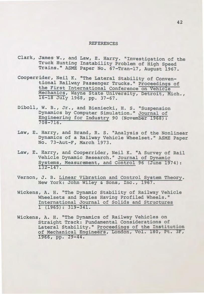
REFERENCES
Clark, James -W .. , and Law, E. Harry. "Investigation of the Truck Hunting Instability Problem of High Speed Trains .. " ASME Paper No. 67-Tran-17, August 1967.
Cooperrider, Neil K. "The Lateral Stability of Conventional Railway Passenger Trucks." Proceedings of the First International Conference on Vehicle Mechanics, Wayne State University, Detroit, Mich., 16-18 July 1968, pp. 37-67.
Diboll, W. B., Jr., and Bieniecki, H. S. "Suspension Dynamics by Computer Simulation. •• Journal of Engineering for Industry 90 (November 1968): 708-716.
Law, E. Harry, and Brand, R. s. "Analysis of the Nonlinear Dynamics of a Railway Vehicle Wheelset." ASME Paper No. 73-Aut-F, March 1973.
Law, E. Harry, and Cooperrider, Neil K. "A Survey of Rail Vehicle Dynamic Research." Journal of Dynamic Systems, Measurement, and Control 96 (June 1974): 132-147.
Vernon, J. B. Linear Vibration and Control S~stem Theory. New York: John Wiley & Sons, Inc., 19 7.
Wickens, A. H. "The Dynamic Stability of Railway Vehicle Wheelsets and Bogies Having Profiled Wheels ... International Journal of Solids and Structures 1 (1965}: 319-341.
Wickens, A. H. "The Dynamics of Railway Vehicles on Straight Track: Fundamental Considerations of Lateral Stability." Proceedings of the Institution of Mechanical Engineers, London, Vol. IBO, Pt. 3F, 1966, pp. 29-44.