Embed Size (px)
Citation preview
IJRET: International Journal of Research in Engineering and Technology eISSN: 2319-1163 | pISSN: 2321-7308
https://doi.org/10.15623/ijret.2018.0705006 Received: 28-02-2018, Accepted: 11-04-2018, Published: 02-05-2018
_______________________________________________________________________________________
Volume: 07 Issue: 05 | May-2018, Available @ www.ijret.org 26
DYNAMIC ANALYSIS OF COMPOSITE STEEL COLUMNS INFILLED
WITH LIGHT WEIGHT CONCRETE (LWC) USING MATLAB (R2013a)
Ramya Shree S C1, N. S. Kumar
2
1Student, Dept. Civil Engineering, Ghousia College of Engineering Ramanagaram, Karnataka, India
2Professor & Director (R&D), Dept. Civil Engineering, Ghousia College of Engineering Ramanagaram, Karnataka,
India
Abstract The Composite Steel Column consists of both Steel and Concrete as main components. In this study, the load carrying capacity of
CFST will be determined for Light Weight Concrete by developing programs using MATLAB software. The behavior of CFST
plays an important role in Seismic design. In this study, the Light Weight Concrete is used as infilled materials of different grades
of concrete like M20, M30, and M40. The required data of CFST columns like length, diameter, and weight are taken from
different National & International research works, including R&D works carried out at Civil Engineering Research Laboratory at
Ghousia College of Engineering, Ramanagaram by previous UG, PG & Research Scholars since 2010 till date. In this study, both
Long and Short columns are considered. Percentage errors between Experimental, Analytical values and MATLAB results are
studied in detail according to Slenderness Ratio of CFST columns. Results are compared with available codes like EUROCODE
4, ACI, BS5400 and suitable conclusions are drawn.
Keywords: Light Weight Concrete, Filled steel tubes, Hollow CFST, MATLAB R2013a etc…
--------------------------------------------------------------------***----------------------------------------------------------------------
1. INTRODUCTION
The Composite Steel Columns are composed of both Steel
and Concrete components. The solid filled steel tubes has
been utilized as a part of numerous zones which is
principally similar to segment supporting structures like
multi-storey buildings, roof of oil stockpiling tanks, columns
for vast modern workshops. Because of its basically
proficient load bearing limit the solid filled steel tubes
utilizes as segments in multi storied structures which is
expanded in late decades.
The concrete filled steel tubes were developed during 19th
century. And the composite steel columns have a many
excellent structural properties such as high compressive
strength, large ductility and large energy absorption
capacity. Concrete steel tubes are used for both unbraced
and propped gathering structures.
The typical figures of CFST sections are as shown in below
figure.
Fig 1: Typical Cross Section of CFST
1.1 Description of Software Used
The name of the software MATLAB stands for matrix
laboratory. The MATLAB is a high performance language
for technical computing. The 3D modeling of CFST
columns infilled with LWC and also hollow CFST columns
are modeled by developing MATLAB programs.
Light Weight Concrete filled in CFST columns and hollow
columns are accurately modeled in MATLAB R2013a
software. The results are verified with available codes.
2. FINITE ELEMENT MODELING
The finite element modeling of CFST columns are done
using MATLAB (R2013a) software by developing the
programs,
2.1 Material Properties
The properties of Steel and Concrete are considered as
follows
Steel properties:
Young’s modulus of steel (Es)=200GPA
Poisons ratio=0.3
Density of steel=7860Kg/m3
Concrete Properties:
Young’s modulus of concrete (Ec) =0.0095(fcyl+8)0.3
(by
referring the journals by the Author of ARTIOMAS
KURANOVAS’)
Poisons ratio=0.2
Density of concrete=2200Kg/m3

IJRET: International Journal of Research in Engineering and Technology eISSN: 2319-1163 | pISSN: 2321-7308
https://doi.org/10.15623/ijret.2018.0705006 Received: 28-02-2018, Accepted: 11-04-2018, Published: 02-05-2018
_______________________________________________________________________________________
Volume: 07 Issue: 05 | May-2018, Available @ www.ijret.org 27
2.2 Modeling of CFST Columns
The 3D modeling of CFST columns of LWC as an infilled
material and hollow CSFT columns for above properties are
created by developing the MATLAB programs. The
MATLAB programs is as shown in below
%% PRAMETER DECLARATION SECTION
LENGTH=202.2;% Length in mm
Outer_Dia=33.7;% Outer Diameter in mm
Inner_Dia=27.3;% Inner Diameter in mm
Weight_in_gram=540;% Weight in Grams
Grades=20;%
Load=182450;%
E_s=20000;%
g=9.81%
Mass=Weight_in_gram/g;%
%% Moment of Inertia, I = Is + Ic (mm4)
I_s= 3.14*((Outer_Dia^4)-(Inner_Dia^4))/64;
I_c=3.14*(Inner_Dia^4)/64;
I=I_s+I_c;
%% (EI)eff = Es Is + C3 Ec Ic (Nmm2)
A_s=3.14*((Outer_Dia^2)-(Inner_Dia^2))/4;
A_c=3.14*(Inner_Dia^2)/4;
C3_C3_0_9=0.6+2*(A_s/(A_c+A_s));
E_c=(5000*(sqrt(Grades)))*(2.3544*10^-5);
E_I_eff=(E_s*I_s)+(0.8*E_c*I_c);
%% TO FIND STIFFNESS AND NATURAL
FREQUENCY
eff_Length=0.65*LENGTH;
Stiffness=(12*E_I_eff)/eff_Length^3;
disp('Stiffness');
disp(Stiffness);
Natural_Frequency=sqrt(Stiffness/Mass);
disp('Natural_Frequency');
disp(Natural_Frequency);
%% TO FIND FOR COLUMN VIBRATION AND FOR
COLUMN BUCKLING
COLUMN_VIBRATION_Lambda1=((Load+((Load^2)+(4
*78000000*((3.14*Outer_Dia^2)/4)*E_I_eff*Natural_Freq
uency^2))^0.5)/(2*E_I_eff))^0.5;
disp('COLUMN_VIBRATION_Lambda1');
disp(COLUMN_VIBRATION_Lambda1);
COLUMN_VIBRATION_Lambda2=((-
Load+((Load^2)+(4*78000000*((3.14*Outer_Dia^2)/4)*E_
I_eff*Natural_Frequency^2))^0.5)/(2*E_I_eff))^0.5;
disp('COLUMN_VIBRATION_Lambda2');
disp(COLUMN_VIBRATION_Lambda2);
COLUMN_BUCKLING_Lambda1=(Load/E_I_eff)^0.5;
disp('COLUMN_BUCKLING_Lambda1');
disp(COLUMN_BUCKLING_Lambda1);
%% TO FIND THE CRITICAL LOADING FOR
INFILLED
critical_loading= ((pi^2)*E_I_eff)/LENGTH^2;
disp('CRITICAL LOADING');
disp(critical_loading);
%% 3-D CFST COLUMN INFILLED LWC
t = linspace(0,2*pi);
rin = 0.27;
rout = 0.3;
center = [0, 0];
zin = rin*cos(t);
zout = rout*cos(t);
yin = rin*sin(t);
yout = rout*sin(t);
x1 = 0;
x2 = 1;
figure(1);
After developing the above programme, the 3D modelling of
CFST columns will be as shown in below figure.
Fig 2: 3D Modelling of CFST column
IJRET: International Journal of Research in Engineering and Technology eISSN: 2319-1163 | pISSN: 2321-7308
https://doi.org/10.15623/ijret.2018.0705006 Received: 28-02-2018, Accepted: 11-04-2018, Published: 02-05-2018
_______________________________________________________________________________________
Volume: 07 Issue: 05 | May-2018, Available @ www.ijret.org 28
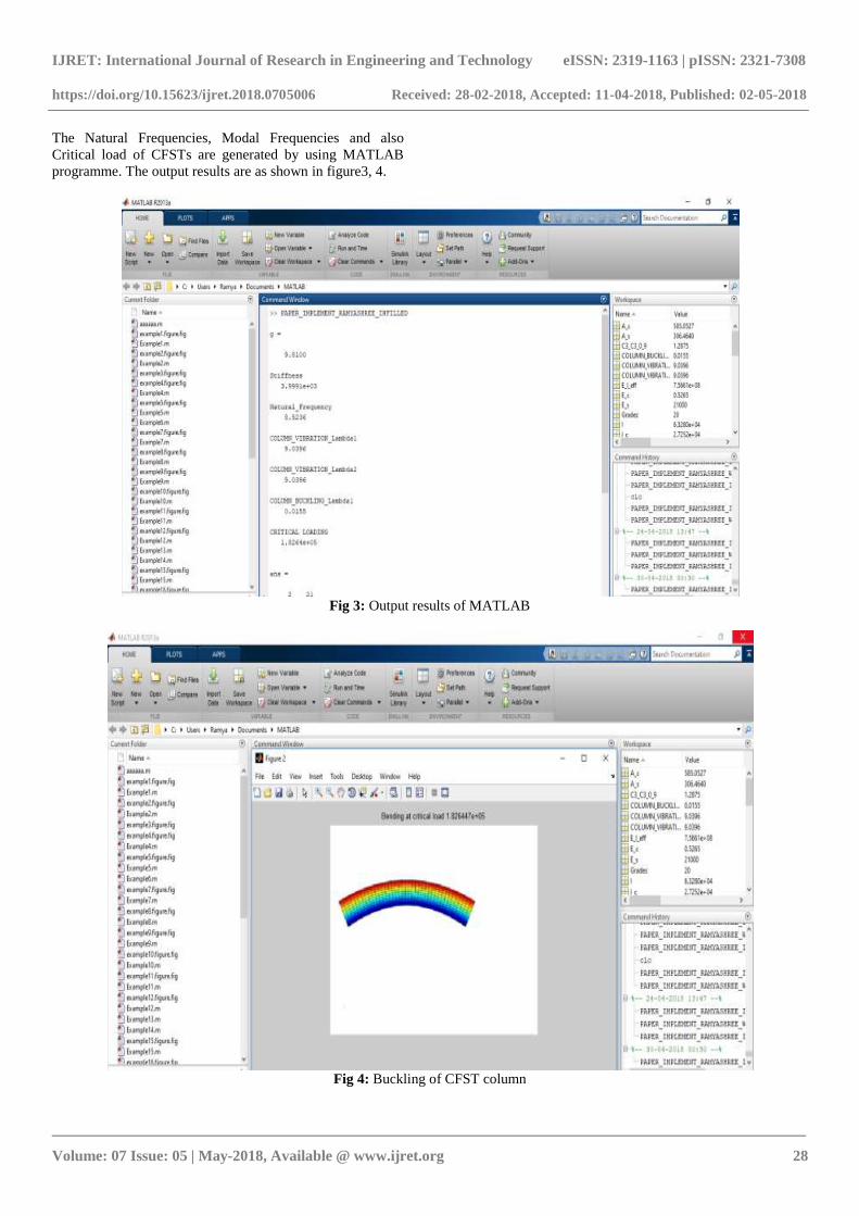
The Natural Frequencies, Modal Frequencies and also
Critical load of CFSTs are generated by using MATLAB
programme. The output results are as shown in figure3, 4.
Fig 3: Output results of MATLAB
Fig 4: Buckling of CFST column

IJRET: International Journal of Research in Engineering and Technology eISSN: 2319-1163 | pISSN: 2321-7308
https://doi.org/10.15623/ijret.2018.0705006 Received: 28-02-2018, Accepted: 11-04-2018, Published: 02-05-2018
_______________________________________________________________________________________
Volume: 07 Issue: 05 | May-2018, Available @ www.ijret.org 29
3. SOLUTION PROCEDURES
The results of Natural Frequencies and Modal Frequencies
of CFST columns and also Critical load of CFST columns
(for both infilled LWC and hollow CFST) for different L/D
ratios and also for different grades of concrete like M20,
M30, M40 are calculated by using below procedures.
3.1 Natural frequency
The natural frequency of CFST columns are calculated by
using below formula
w (rsd)=(k/m)0.5
Where, w=Natural frequency in rad
k= stiffness of CFST in N/mm
m=mass of CFST in N-sec2/mm
3.2 Modal Frequencies
The Modal Frequency for CFST is calculated by using the
following formula
For column vibration:
λ1=sqrt (P+P2+4ρ*sqrt ((π*D
2/4)*EI*wn
2))/ (2*EI))
λ2= sqrt (-P+P2+4ρ*sqrt ((π*D
2/4)*EI*wn
2))/ (2*EI))
Where, P=crippling load in N
D=Outer diameter in mm
Wn=Natural frequency in rad
For column buckling:
λ1=sqrt (P/EI)
3.3 Critical Load
To check the accuracy of Critical loading obtained from
MATLAB are compared with available codes. The Critical
loading of CFST columns are calculated by using the
formula as mentioned in below.
Ncr= (π2 (EI) eff)/L
2
Where (EI) eff=effective elastic flexural stiffness of concrete
sections, and L is the buckling length of column.
(EI)eff=EaIa+0.8EcdIc for short columns
(EI)eff=EaIa+0.6EcIc for short columns
Where Ia and Ic are the moment of inertia of steel and
concrete.
Ea= elastic modulus of steel structures.
Ecd=Ecm/γc
Ecm= mean value of concrete elasticity modulus
γc=partial safety factor of concrete which is reduced to 1.35
The results are compared with following codes:
3.3.1 Euro Code 4
The Critical load of CFST columns are calculated by using
below formula according to Euro code 4
Ncr=Asfs+Acfc
3.3.2 ACI Code
The Critical load of CFST columns are calculated by using
the below formula according to American Concrete Institute
Ncr=Asfs+0.85Acfc
3.3.3 BS5400 Code
The Critical load of CFST columns are calculated by using
the below formula according to British Standards 5400
Ncr=Asfs+0.675Acfc
Where, As= area of steel in mm2
fs= yield strength of steel in N/mm2
Ac=area of concrete in mm2
fc=characteristic strength of concrete in N/mm2
4. VERIFICATIONS OF RESULTS
The Experimental, Analytical, MATLAB results of Natural
frequencies and Modal Frequencies and also Critical loading
of CFST columns (for both infilled LWC and hollow) of
different L/D ratio and also different grades of concrete are
compared with codes is as shown in below
Table 1: Comparison of Natural Frequency with MATLAB
Lengt
h
Grade
s
Natural
frequency(Analyt
ic)
Natural
frequency(MATLA
B)
L
(mm) M w(rad) w(rad)
202.2
M20 8.318144571 8.5236
M30 7.738045 7.9291
M40 7.54695 7.7333
Hollo
w 8.99288 9.234
254.4
M20 6.0263477 6.186
M30 5.939948 6.053
M40 5.877537 6.034
Hollo
w 7.952923 8.152
339.2
M20 3.963534 4.1254
M30 3.91782 4.0012
M40 3.71541 3.8081
Hollo
w 4.8406466 4.9821
424
M20 2.089496 2.1542
M30 1.96344787 2.01325
M40 1.9357695 2.0124
Hollo 2.649766192 2.7235
IJRET: International Journal of Research in Engineering and Technology eISSN: 2319-1163 | pISSN: 2321-7308
https://doi.org/10.15623/ijret.2018.0705006 Received: 28-02-2018, Accepted: 11-04-2018, Published: 02-05-2018
_______________________________________________________________________________________
Volume: 07 Issue: 05 | May-2018, Available @ www.ijret.org 30
w
508.8
M20 1.516685 1.5683
M30 1.46175 1.4978
M40 1.41381 1.4512
Hollo
w 1.81067166 1.8592
594.6
M20 1.058918 1.1534
M30 1.042125001 1.0684
M40 1.0278495 1.0546
Hollo
w 1.33913 1.3856
678.4
M20 1.014745 1.3845
M30 1.0114761 1.0364
M40 1.011247 1.01145
Hollo
w 1.150548 1.1834
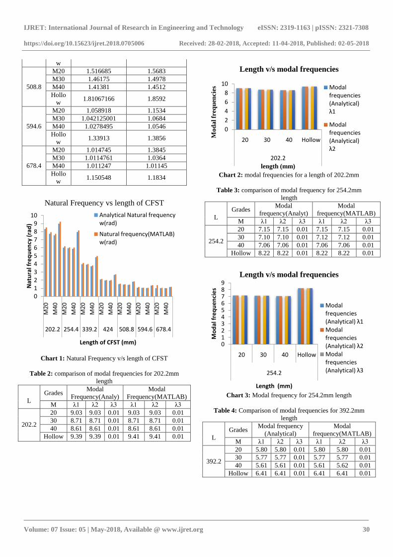
Chart 1: Natural Frequency v/s length of CFST
Table 2: comparison of modal frequencies for 202.2mm
length
L
Grades Modal
Frequency(Analy)
Modal
Frequency(MATLAB)
M λ1 λ2 λ3 λ1 λ2 λ3
202.2
20 9.03 9.03 0.01 9.03 9.03 0.01
30 8.71 8.71 0.01 8.71 8.71 0.01
40 8.61 8.61 0.01 8.61 8.61 0.01
Hollow 9.39 9.39 0.01 9.41 9.41 0.01
Chart 2: modal frequencies for a length of 202.2mm
Table 3: comparison of modal frequency for 254.2mm
length
L
Grades Modal
frequency(Analyt)
Modal
frequency(MATLAB)
M λ1 λ2 λ3 λ1 λ2 λ3
254.2
20 7.15 7.15 0.01 7.15 7.15 0.01
30 7.10 7.10 0.01 7.12 7.12 0.01
40 7.06 7.06 0.01 7.06 7.06 0.01
Hollow 8.22 8.22 0.01 8.22 8.22 0.01
Chart 3: Modal frequency for 254.2mm length
Table 4: Comparison of modal frequencies for 392.2mm
length
L
Grades Modal frequency
(Analytical)
Modal
frequency(MATLAB)
M λ1 λ2 λ3 λ1 λ2 λ3
392.2
20 5.80 5.80 0.01 5.80 5.80 0.01
30 5.77 5.77 0.01 5.77 5.77 0.01
40 5.61 5.61 0.01 5.61 5.62 0.01
Hollow 6.41 6.41 0.01 6.41 6.41 0.01
0123456789
10
M2
0
M4
0
M2
0
M4
0
M2
0
M4
0
M2
0
M4
0
M2
0
M4
0
M2
0
M4
0
M2
0
M4
0
202.2 254.4 339.2 424 508.8 594.6 678.4
Nat
ura
l fre
qu
en
cy (
rad
)
Length of CFST (mm)
Natural Frequency vs length of CFST
Analytical Natural frequency w(rad)
Natural frequency(MATLAB) w(rad)
0
2
4
6
8
10
20 30 40 Hollow
202.2
Mo
da
l fr
eq
uen
cies
length (mm)
Length v/s modal frequencies
Modal frequencies (Analytical) λ1
Modal frequencies (Analytical) λ2
0123456789
20 30 40 Hollow
254.2
Mo
dal
fre
qu
en
cie
s
Length (mm)
Length v/s modal frequencies
Modal frequencies (Analytical) λ1Modal frequencies (Analytical) λ2Modal frequencies (Analytical) λ3
IJRET: International Journal of Research in Engineering and Technology eISSN: 2319-1163 | pISSN: 2321-7308
https://doi.org/10.15623/ijret.2018.0705006 Received: 28-02-2018, Accepted: 11-04-2018, Published: 02-05-2018
_______________________________________________________________________________________
Volume: 07 Issue: 05 | May-2018, Available @ www.ijret.org 31
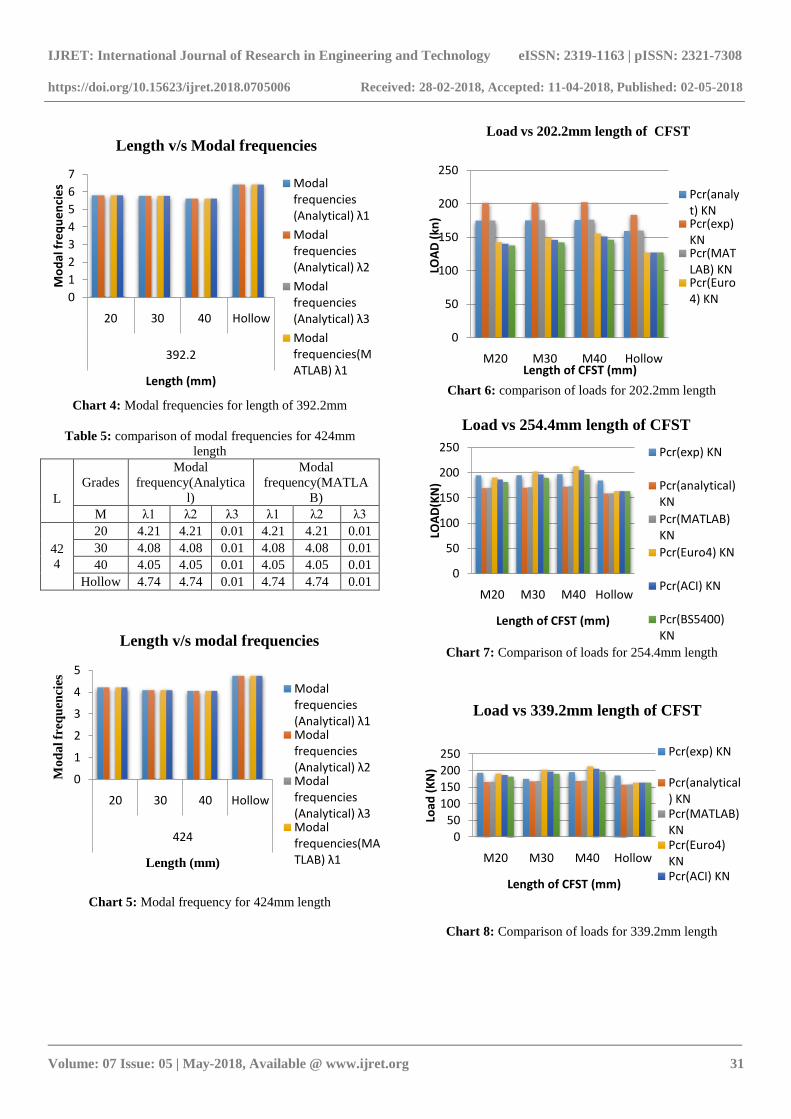
Chart 4: Modal frequencies for length of 392.2mm
Table 5: comparison of modal frequencies for 424mm
length
L
Grades
Modal
frequency(Analytica
l)
Modal
frequency(MATLA
B)
M λ1 λ2 λ3 λ1 λ2 λ3
42
4
20 4.21 4.21 0.01 4.21 4.21 0.01
30 4.08 4.08 0.01 4.08 4.08 0.01
40 4.05 4.05 0.01 4.05 4.05 0.01
Hollow 4.74 4.74 0.01 4.74 4.74 0.01
Chart 5: Modal frequency for 424mm length
Chart 6: comparison of loads for 202.2mm length
Chart 7: Comparison of loads for 254.4mm length
Chart 8: Comparison of loads for 339.2mm length
0
1
2
3
4
5
6
7
20 30 40 Hollow
392.2
Mo
dal
fre
qu
en
cie
s
Length (mm)
Length v/s Modal frequencies
Modal frequencies (Analytical) λ1
Modal frequencies (Analytical) λ2
Modal frequencies (Analytical) λ3
Modal frequencies(MATLAB) λ1
0
1
2
3
4
5
20 30 40 Hollow
424
Mo
da
l fr
eq
uen
cies
Length (mm)
Length v/s modal frequencies
Modal frequencies (Analytical) λ1Modal frequencies (Analytical) λ2Modal frequencies (Analytical) λ3Modal frequencies(MATLAB) λ1
0
50
100
150
200
250
M20 M30 M40 Hollow
LOA
D (
kn)
Length of CFST (mm)
Load vs 202.2mm length of CFST
Pcr(analyt) KNPcr(exp) KNPcr(MATLAB) KNPcr(Euro4) KN
0
50
100
150
200
250
M20 M30 M40 Hollow
LOA
D(K
N)
Length of CFST (mm)
Load vs 254.4mm length of CFST
Pcr(exp) KN
Pcr(analytical) KN
Pcr(MATLAB) KN
Pcr(Euro4) KN
Pcr(ACI) KN
Pcr(BS5400) KN
0
50
100
150
200
250
M20 M30 M40 Hollow
Load
(K
N)
Length of CFST (mm)
Load vs 339.2mm length of CFST
Pcr(exp) KN
Pcr(analytical) KNPcr(MATLAB) KNPcr(Euro4) KNPcr(ACI) KN

IJRET: International Journal of Research in Engineering and Technology eISSN: 2319-1163 | pISSN: 2321-7308
https://doi.org/10.15623/ijret.2018.0705006 Received: 28-02-2018, Accepted: 11-04-2018, Published: 02-05-2018
_______________________________________________________________________________________
Volume: 07 Issue: 05 | May-2018, Available @ www.ijret.org 32
Chart 9: Comparison of loads for 424mm length
Chart 10: Comparison of loads for 508.8mm length
Chart 11: Comparison of loads for 594.6mm length
Chart 12: Comparison of loads for 678.4mm length
5. CONCLUSION
In this study the following conclusions are drawn,
[1]. As the Column Length increases, the Load Carrying
Capacity of CFST is decreased by 2.36%.
[2]. As Slenderness Ratio (L/D) increases, Load Carrying
Capacity of CFST is decreased by 2.36%.
[3]. As Grades of Light Weight Concrete increases (i.e.
M20, M30, and M40), Load Carrying Capacity of CFST
column increased by 0.651% for a Column of Constant
Length.
[4]. For Particular Grade of Concrete Load Carrying
Capacity increased by 2 to 5% for 15 to 16% increased in
Column Length.
[5]. For 15 to 16% increased in Column Length, Load
Carrying Capacity is decreased by 1.5 to 5%.
[6]. As Grades of Concrete increases and for 15 to 16%
Column Length increases, then percentage increases in Load
Carrying Capacity was found to be very nominal 0.5 to 1%.
[7]. For Short Columns (λ<12), Ultimate Load obtained
from developing MATLAB programming varying by 0.45%
when compared with Analytical Results by referring the
Journals of Load Bearing Capacity of Concrete Filled Steel
Columns by the ARTIOMAS KURANOVAS’ for M20
Grades of Concrete.
[8]. For Long Columns (λ>12), Ultimate Load obtained
from developing MATLAB programming varying by
0.419% when compared with Analytical Results by referring
the Journals Of Load Bearing Capacity Of Concrete Filled
Steel Columns by the ARTIOMAS KURANOVAS’ for
M20 Grades of Concrete.
[9]. For Short Columns (λ<12), Ultimate Load obtained
from developing MATLAB programming varying by
0.534% when compared with Analytical Results by referring
the Journals Of Load Bearing Capacity Of Concrete Filled
Steel Columns by the ARTIOMAS KURANOVAS’ for
M30 Grades Of Concrete.
0
50
100
150
200
250
M20 M30 M40 Hollow
Load
(K
N)
Length of CFST (mm)
Load vs 424mm length of CFST
Pcr(exp) KN
Pcr(analytical) KN
Pcr(MATLAB) KN
Pcr(Euro4) KN
Pcr(ACI) KN
0
50
100
150
200
250
M20 M30 M40 Hollow
Load
(K
N)
Length of CFST(mm)
Load vs 508.8mm length of CFST
Pcr(exp) KN
Pcr(analytical) KNPcr(MATLAB) KNPcr(Euro4) KN
Pcr(ACI) KN
0
50
100
150
200
250
M20 M30 M40 Hollow
Load
(K
N)
Length of CFST(mm)
Load vs 594.6mm length of CFST
Pcr(exp) KN
Pcr(analytical) KN
Pcr(MATLAB) KN
Pcr(Euro4) KN
Pcr(ACI) KN
0
50
100
150
200
250
300
M20 M30 M40 Hollow
LOA
D (
mm
)
Length of CFST(mm)
Load vs 678.4mm length of CFST
Pcr(exp) KN
Pcr(analytical) KNPcr(MATLAB) KNPcr(Euro4) KNPcr(ACI) KN
IJRET: International Journal of Research in Engineering and Technology eISSN: 2319-1163 | pISSN: 2321-7308
https://doi.org/10.15623/ijret.2018.0705006 Received: 28-02-2018, Accepted: 11-04-2018, Published: 02-05-2018
_______________________________________________________________________________________
Volume: 07 Issue: 05 | May-2018, Available @ www.ijret.org 33
[10]. For Long Columns (λ>12), Ultimate Load obtained
from developing MATLAB programming varying by 0.39%
when compared with Analytical Results by referring the
Journals Of Load Bearing Capacity Of Concrete Filled Steel
Columns by the ARTIOMAS KURANOVAS’ for M30
Grades Of Concrete.
[11]. For Short Columns (λ<12), Ultimate Load obtained
from developing MATLAB programming varying by
0.618% when compared with Analytical Results by referring
the Journals Of Load Bearing Capacity Of Concrete Filled
Steel Columns by the ARTIOMAS KURANOVAS’ for
M40 grades of concrete.
[12]. For Long Columns (λ>12), Ultimate Load obtained
from developing MATLAB programming varying by
0.361% when compared with Analytical Results by referring
the Journals Of Load Bearing Capacity Of Concrete Filled
Steel Columns by the ARTIOMAS KURANOVAS’ for
M40 Grades Of Concrete.
[13]. For Short Columns (λ<12), Ultimate Load obtained
from developing MATLAB programming varying by
0.447% when compared with Analytical Results by referring
the Journals Of Load Bearing Capacity Of Concrete Filled
Steel Columns by the ARTIOMAS KURANOVAS’ for
Hollow CFST.
[14]. For Long Columns (λ>12), Ultimate Load obtained
from developing MATLAB programming varying by
0.433% when compared with Analytical Results by referring
the Journals Of Load Bearing Capacity Of Concrete Filled
Steel Columns by the ARTIOMAS KURANOVAS’ for
Hollow CFST.
[15]. Results obtained by developing MATLAB
programming is compared with 3 different codes i.e.
EUROCODE 4, ACI, BS5400, in which EUROCODE4
gives better results in comparison with Analytical,
Experimental and MATLAB results.
[16]. As Length of Column increases, the Natural
Frequency of column decreases by 20% to 25%.
[17]. For Particular Grade of concrete, the Natural
Frequency decreased by 20% to 25% (for 15% to 16%
length increase)
[18]. As Grade of Concrete increases, the Natural Frequency
found to decrease by 4 %to 6%. (Length being constant)
[19]. For Change in Length of Column, the Natural
Frequency obtained from developing MATLAB
programming varied between 2% to 2.5% when compared
with Analytical results.
[20]. As Column Length increases, the Modal Frequencies
were observed to decrease.
[21]. For Particular Grade of Concrete (for 12% to 16 %of
increased length), the Modal Frequencies decreased by 8%
to 12%.
[22]. For Constant Length and for increased grade of
concrete, Modal Frequencies decreased by 3.5% to 5%.
REFERENCES
[1] ACI (American Concrete Institute), Building code
requirements for structural concrete and commentary,
ACI318-95.
[2] Euro code 4 for design of composite steel structures,
in part 1.1 general rules for buildings.
[3] Euro code 2 for properties of steel and concrete for
design of composite steel structures.
[4] BS5400 for design of concrete filled steel columns,
and for finding critical load of CFST columns.
[5] IJRET: International Journals of Research in
Engineering and Technology dynamic behavior or
composite filled circular steel tubes with light weight
concrete as infilled.
[6] Zhijing Ou1; Baouchun Chen, P.E.
2;Kai H. Hsieh
3;
experimental and analytical investigation of concrete
filled steel tubular columns.
[7] Artiomas Kuranovas1, Douglas Goode
2,Audronis
Kazimieras Kvedaras3,Shantong Zhong
4 of “Load
bearing capacity of concrete-filled steel columns”.
[8] Structural Dynamics of Earthquake Engineering,
theory and application uses of MATLAB by
Rajashekaran.
[9] Concrete technology text book by the author of M S
Shetty.
[10] www.google.com
BIOGRAPHIES
Graduated in the year 2016 from
VTU, Belgaum. Presently perusing
Master of Technology in Structural
Engineering at Ghousia College of
Engineering, Ramanagaram Also
working on this topic for the
dissertation under the guidance of Dr.
N S Kumar.
Involved in the Research field related
to behavior of Composite Steel
Column since a decade. Presently
guiding 6 Ph.D Scholars (Research
under VTU, Belgaum). Has more
than 29 years of teaching experience
& 6 years of Research experience at
Ghousia College of Engineering,
Ramanagaram.