Embed Size (px)
Citation preview
I J C T A, 9(17) 2016, pp. 8745-8753© International Science Press
* Research scholar, Department of Mechanical Engineering, Delhi Technological University, Delhi-110042, INDIA, E-mail:[email protected]
** Professor, Department of Mechanical Engineering, Delhi Technological University, Delhi-110042, INDIA, E-mail:[email protected]
Dynamic Analysis and Control of a Full CarVehicle Model through BondgraphsAshish Gupta* and Vikas Rastogi**
ABSTRACT
In present scenario, controller plays a very significant role in dynamical system, as it greatly affects the dynamicsof the vehicle according to its influence on the achievable sources. It is mainly considered that the interactionbetween controller and body is one of the most important tasks of vehicle modelling. This work shows the developmentof a controller interaction model in multi-energy domains using bond graph approach. The main focus of the paperis modelling the spatial (3-dimensional) vehicle modelling of the complex dynamics. In this work, 3-dimensionalvehicle model incorporated with 3-dimensional tire model of car has been developed through bond graph approach.
The simulation of the model is being carried out on Symbols sonata® software, which shows some interestingphenomenon.
Further the model incorporate with Proportional Integrated (PI) controller in the suspension system of vehiclemodel. Afterwards, the simulation study has been performed which is compared with the previous simulation. Theproportional and integral gain has been optimized numerically to further apply real vehicle application.
Key words: PI controller; spatial vehicle model; bondgraphs.
I. INTRODUCTION
The increasing demands on vehicles together with relatively cheap and powerful electronics and actuatortechnology enable to extend purely mechanical systems with new control features. Such multidisciplinarysystems together with requirement for shorter development time, lower development costs and new qualityof products being developed have raised new CAE tools.Suspension systems are designed to maintainvehicle stability by reducing the effects of dynamic loads while providing a comfortable ride via the reductionof impulse forces from terrain features [1]. The word suspension originated from the original attempts ofsuspending the carriage body by leather straps from a framework connected to the wheels. As defined byWong [2] ride is concerned with the sensation or feel of the passenger in the environment of a movingvehicle. Problems arise mainly from vibrations of the vehicle body, induced by sources such as aerodynamicforces and vibrations from the power train, drive train and road. As stated by Hrovat [3], vertical groundinput disturbances caused by road roughness are the most relevant for ride studies. There are various studiesof modelling and simulation, where vehicle has been modelled through bond graphs for evaluating a dynamicbehaviour [4]. However some studies have incorporated different types of controller in suspension system[5,6].
Semi-active suspensions are similar to passive suspensions except they possess variable damping rates[7].Since the vibration suppression capabilities of the traditional passive and semi-active suspension systemsare restricted, an active suspension system with additional control force to suppress the oscillations is oneof the major development fields in recent vehicle industry. Fully active suspension system use hydraulicactuator which creates the desired force in the suspension system [8,9,10].
8746 Ashish Gupta and Vikas Rastogi
This paper presents with the multi-rigid body theory through bond graph technique for modelling of acomplex spatial car model. Primarily, bond graphs (BG) represent elementary energy-related phenomenonusing a small set of ideal elements that can be coupled together through external ports representing powerflow. With the aids of bond graphs, hierarchal modelling becomes possible through coupling energy exchangephenomenon, it is also possible to code on the graph the mathematical structure of the physical system toshow the causal relation- ship( in computational relationship) among its signals. The conjunction of allthese feature make the bond graph technique a physical based, object oriented, graphical language, whichis most suitable for dynamic modelling, analysis and simulation of complex engineering system involvingmixed physical and technical domains in their constitution [11].
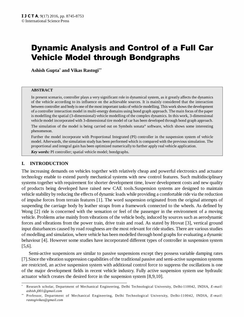
This paper also incorporates the PI control system (which is combined form of proportional and integratedcontroller) to the vehicle suspension system with an objective to reduce vehicle jerks and increase comfortlevel of driver. The physical model of the vehicle structure is shown in fig.1. This vehicle is composed ofcomponents such as car model, suspension and wheels. Each component of vehicle act as a rigid body.
Figure 1: Three-dimensional car model of the vehicle
In the Fig.1 C.G of body is located at ‘h’ height above the axle of the vehicle; rear suspension isdistance at ‘l’ simultaneously from C.G. the width of the vehicle is taken as ‘2w’. It has accommodatedthree modes pitching, rolling and steering and linear vertical motion.
II. COMPUTATIONAL MODELLING
This section represents the generalized form of mathematical model and addresses the essential issuesconcerning the bondgraph modelling of multi-body system as used in this system.There are variousassumption made for construction this model: 1) The components of vehicle body act as a rigid body. 2)The spring and dampers of the suspension system elements have linear characteristics.3) the spring dampersystem is assumed to be mass less.4) the tires of the vehicle remain in contact with the road at all times. 5)Straight road is assumed.6) Bump type surface irregularity is assumed for both the wheel (rear and front).
(A) Chassis
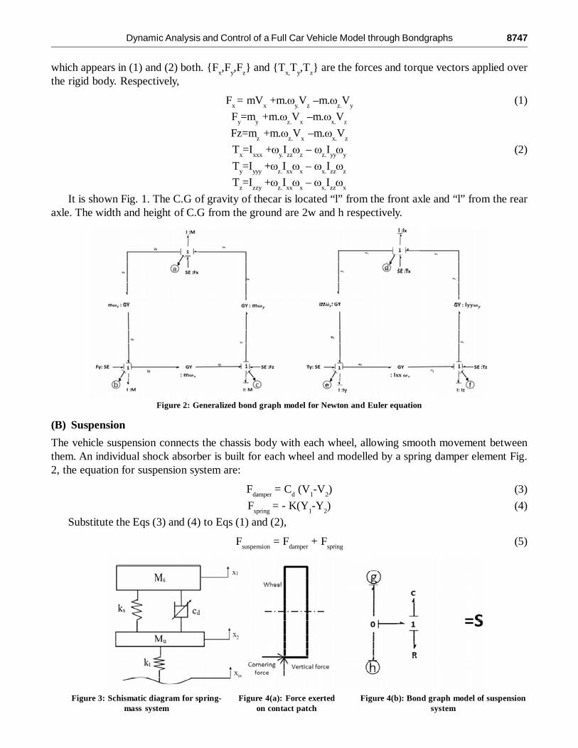
The chassis of car modelled as a rigid body, represents a sprung mass by means of wheel shock absorbers.The model has 6-degree of freedom 3-translational and –rotational movements with respect to XYZ axis.The spatial model motions in local frame are determined through well-known Newton Euler equation,
Dynamic Analysis and Control of a Full Car Vehicle Model through Bondgraphs 8747
which appears in (1) and (2) both. {Fx,F
y,F
z} and {T
x,T
y,T
z} are the forces and torque vectors applied over
the rigid body. Respectively,
Fx = mV
x +m.�
y.V
z –m.�
z.V
y(1)
Fy=m
y +m.�
z.V
x –m.�
x.V
z
Fz=mz +m.�
z.V
x –m.�
x.V
z
Tx=I
xxx +�
y.I
zz�
z – �
z.I
yy�
y(2)
Ty=I
yyy +�
z.I
xx�
x – �
x.I
zz�
z
Tz=I
zzy +�
z.I
xx�
x – �
x.I
zz�
x
It is shown Fig. 1. The C.G of gravity of thecar is located “l” from the front axle and “l” from the rearaxle. The width and height of C.G from the ground are 2w and h respectively.
Figure 2: Generalized bond graph model for Newton and Euler equation
(B) Suspension
The vehicle suspension connects the chassis body with each wheel, allowing smooth movement betweenthem. An individual shock absorber is built for each wheel and modelled by a spring damper element Fig.2, the equation for suspension system are:
Fdamper
= Cd (V
1-V
2) (3)
Fspring
= - K(Y1-Y
2) (4)
Substitute the Eqs (3) and (4) to Eqs (1) and (2),
Fsuspension
= Fdamper
+ Fspring
(5)
Figure 3: Schismatic diagram for spring-mass system
Figure 4(a): Force exertedon contact patch
Figure 4(b): Bond graph model of suspensionsystem
8748 Ashish Gupta and Vikas Rastogi
(C) Wheels
The wheels are modelled by their mass, rotary inertia, radius and tyre stiffness. The tyre is the most importantamong wheel components because tyre forces and moments play in important role in vehicle dynamics.Tyre forces are necessary to control the vehicle. As the tyres are the only means of contact between the roadand the vehicle, they are the key factors determining the vehicle handling performance. Tyre models arebroadly classified as physical models, analytical models, and empirical models. The physical models areconstructed to predict tyre elastic deformation and tyre forces. Paceja’s magic formula is a widely usedempirical model with which one can compute the longitudinal and cornering forces and self-aligning moment[12].
The principle model of tire is presented in Fig. The wheel is also act as a rigid body, which have sixdegree of freedom. Similar to chassis body, the inertias are coupled by a pair of gyrator rings. The tyre-roadnormal contact force and the gravity force always act along inertial Z-axis. Thus the wheel vertical dynamicsis coupled with longitudinal and lateral dynamics. The ground reaction force (Fz) and wheel radius (r
w) is
used to modulate longitudinal and cornering dynamics, which are given in axle body-fixed frame.
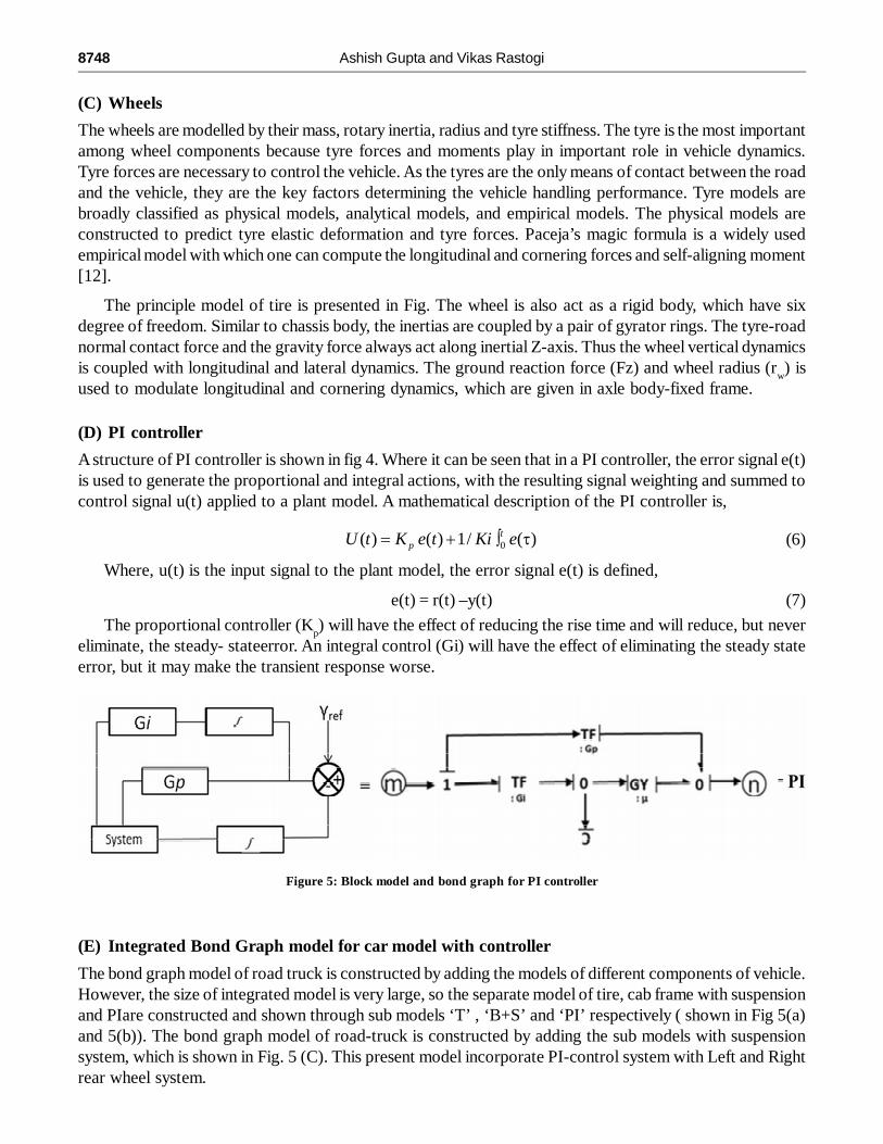
(D) PI controller
A structure of PI controller is shown in fig 4. Where it can be seen that in a PI controller, the error signal e(t)is used to generate the proportional and integral actions, with the resulting signal weighting and summed tocontrol signal u(t) applied to a plant model. A mathematical description of the PI controller is,
0( ) ( ) 1/ ( )tpU t K e t Ki e� � � � (6)
Where, u(t) is the input signal to the plant model, the error signal e(t) is defined,
e(t) = r(t) –y(t) (7)
The proportional controller (Kp) will have the effect of reducing the rise time and will reduce, but never
eliminate, the steady- stateerror. An integral control (Gi) will have the effect of eliminating the steady stateerror, but it may make the transient response worse.
Figure 5: Block model and bond graph for PI controller
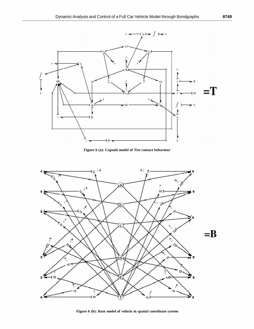
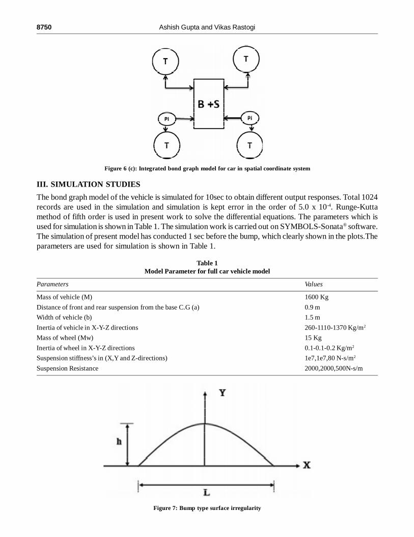
(E) Integrated Bond Graph model for car model with controller
The bond graph model of road truck is constructed by adding the models of different components of vehicle.However, the size of integrated model is very large, so the separate model of tire, cab frame with suspensionand PIare constructed and shown through sub models ‘T’ , ‘B+S’ and ‘PI’ respectively ( shown in Fig 5(a)and 5(b)). The bond graph model of road-truck is constructed by adding the sub models with suspensionsystem, which is shown in Fig. 5 (C). This present model incorporate PI-control system with Left and Rightrear wheel system.
Dynamic Analysis and Control of a Full Car Vehicle Model through Bondgraphs 8749
Figure 6 (a): Capsule model of Tire contact behaviour
Figure 6 (b): Base model of vehicle in spatial coordinate system
8750 Ashish Gupta and Vikas Rastogi
III. SIMULATION STUDIES
The bond graph model of the vehicle is simulated for 10sec to obtain different output responses. Total 1024records are used in the simulation and simulation is kept error in the order of 5.0 x 10⁻⁴. Runge-Kuttamethod of fifth order is used in present work to solve the differential equations. The parameters which isused for simulation is shown in Table 1. The simulation work is carried out on SYMBOLS-Sonata® software.The simulation of present model has conducted 1 sec before the bump, which clearly shown in the plots.Theparameters are used for simulation is shown in Table 1.
Table 1Model Parameter for full car vehicle model
Parameters Values
Mass of vehicle (M) 1600 Kg
Distance of front and rear suspension from the base C.G (a) 0.9 m
Width of vehicle (b) 1.5 m
Inertia of vehicle in X-Y-Z directions 260-1110-1370 Kg/m2
Mass of wheel (Mw) 15 Kg
Inertia of wheel in X-Y-Z directions 0.1-0.1-0.2 Kg/m2
Suspension stiffness’s in (X,Y and Z-directions) 1e7,1e7,80 N-s/m2
Suspension Resistance 2000,2000,500N-s/m
Figure 6 (c): Integrated bond graph model for car in spatial coordinate system
Figure 7: Bump type surface irregularity
Dynamic Analysis and Control of a Full Car Vehicle Model through Bondgraphs 8751
3.1. Half sine bump
A sinusoidal profile of the road has been considered for simulation, which is shown in Fig. 6. The transientinput chosen is a half sine bump and vehicle velocity is taken 60 m/s for analysis.
As a function of time, the road conditions are given by
(8)
(9)
where, h is the height of the bump, which is 0.1m; is the length of the bump, which is 0.3m; t is the time andis the velocity of the vehicle.
Following output parameters are obtained in the simulation of the bond graph model of the completetruck model:
IV. RESULTS AND DISCUSSION
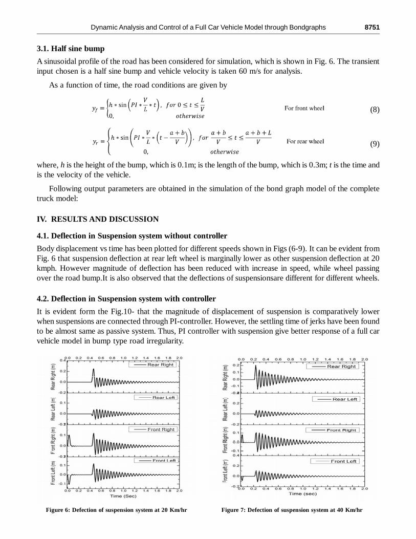
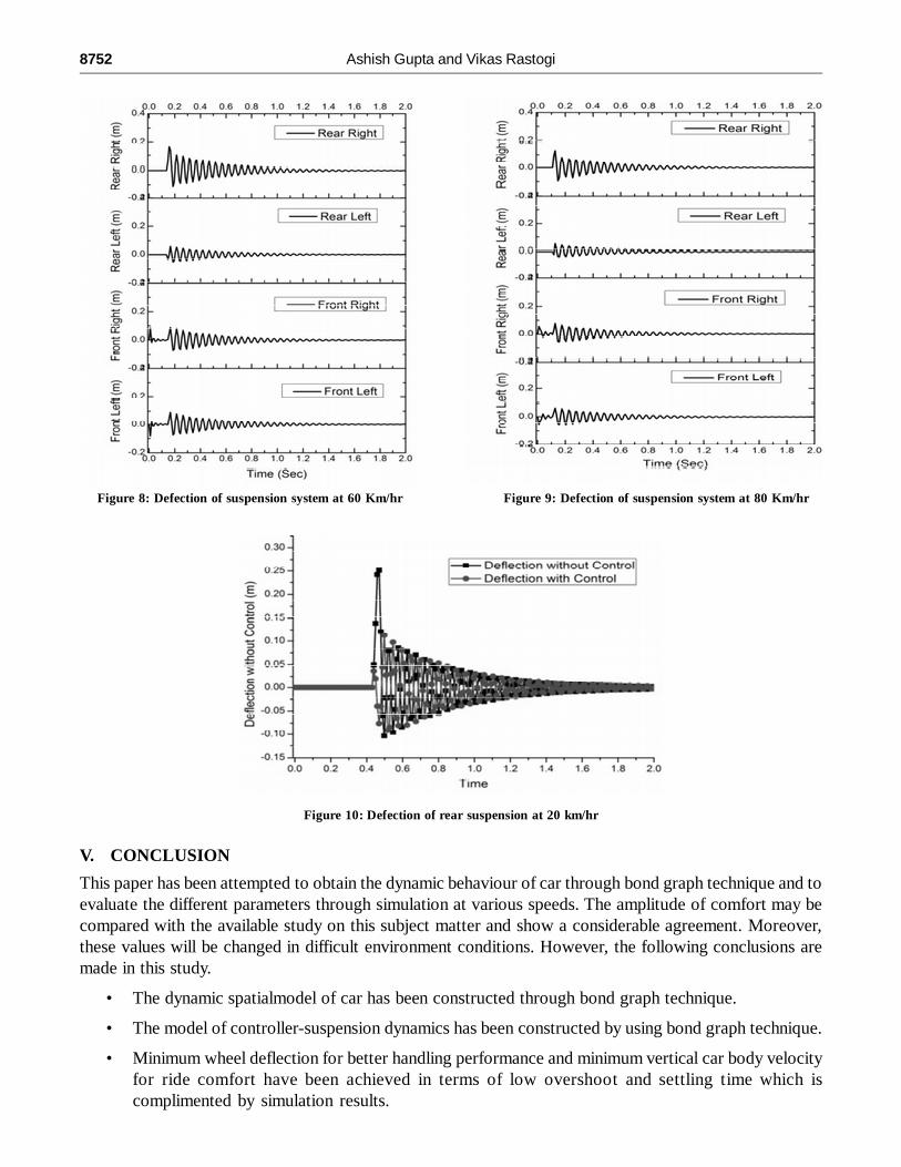
4.1. Deflection in Suspension system without controller
Body displacement vs time has been plotted for different speeds shown in Figs (6-9). It can be evident fromFig. 6 that suspension deflection at rear left wheel is marginally lower as other suspension deflection at 20kmph. However magnitude of deflection has been reduced with increase in speed, while wheel passingover the road bump.It is also observed that the deflections of suspensionsare different for different wheels.
4.2. Deflection in Suspension system with controller
It is evident form the Fig.10- that the magnitude of displacement of suspension is comparatively lowerwhen suspensions are connected through PI-controller. However, the settling time of jerks have been foundto be almost same as passive system. Thus, PI controller with suspension give better response of a full carvehicle model in bump type road irregularity.
Figure 6: Defection of suspension system at 20 Km/hr Figure 7: Defection of suspension system at 40 Km/hr
8752 Ashish Gupta and Vikas Rastogi
Figure 10: Defection of rear suspension at 20 km/hr
Figure 8: Defection of suspension system at 60 Km/hr Figure 9: Defection of suspension system at 80 Km/hr
V. CONCLUSION
This paper has been attempted to obtain the dynamic behaviour of car through bond graph technique and toevaluate the different parameters through simulation at various speeds. The amplitude of comfort may becompared with the available study on this subject matter and show a considerable agreement. Moreover,these values will be changed in difficult environment conditions. However, the following conclusions aremade in this study.
• The dynamic spatialmodel of car has been constructed through bond graph technique.
• The model of controller-suspension dynamics has been constructed by using bond graph technique.
• Minimum wheel deflection for better handling performance and minimum vertical car body velocityfor ride comfort have been achieved in terms of low overshoot and settling time which iscomplimented by simulation results.
Dynamic Analysis and Control of a Full Car Vehicle Model through Bondgraphs 8753
• The incorporation of controller has been improved the performance of passive suspension system.
• Further this computational may also be attempted to evaluate a steering and rolling effect on dynamicsof the vehicle.
REFERENCES[1] Miller L. R (1988), “Tuning passive, semi-active, and fully active suspension systems”, in Proc. 27th IEEE conference on
decision and control, Vol 3., pp. 2047-2053.
[2] Wong J.Y. (1993) “Theory of Ground Vehicles- Second Edition”, John Wiley & Sons Inc., New work.
[3] Hrovat, D. (1997) “ Survey of Advanced Suspension Developments and Related Optimal Control and Applications”,Automatica, Vol. 33, PP 1781-1817.
[4] Ashish Gupta, VikasRastogi, “ Effects of Various Road Conditions on Dynamic Behaviour of Heavy Road Vehicle”Procedia Engineering144( 2016 ) 1129 –1137.
[5] Ashish Gupta, VikasRastogi “Dynamic Modelling and Control of Off-Road Truck Using Bondgraphs” advances in intelligentand soft computing,DOI: 10.1007/978-81-322-0491-6-41.
[6] Ashish Gupta, VikasRastogi, “Dynamic Modeling and control of off-road truck using bond graphs with PID controller”,proceedings of the Int. Conf. on Integrated Modeling and Analysis in Applied Control and Automation, 2013, DOI:10.13140/RG.2.1.2252.6569.
[7] Mouleeswaran S.K. (2008) “ Development of Active Suspension System for automobiles using PID controller,” proceedingof the world congress on Engineering, London, U.K.
[8] Sun Jianmin, and Sun Yi, (2011)” Comparative Study on control strategy of active suspension system,” 3rd InternationalConference on ICMTMA, pp. 729-732.
[9] Ashari A.E (2004)” Sliding mode control of active suspension system: Unit vector approach,” Proc. of IEEE Intern. Conf.on control Applications, vol.1, PP. 370-375.
[10] Hashemipour H, Amiri M., Mirzaei M. and Maghoul, A (2009) “ Nonlinear control of vehicle active suspension consideringactive dynamics,” 2nd Intern Conf. on Computer and Electrical Engineering, vol.2, pp. 262-366.
[11] Chen Po-Chang, and Huang An-Chyau (2005) “ Adaptive sliding control of autonomous active suspension systems withtime –varying loadings,” Journal of Sound and Vibration, vol.282, pp. 119-1135.
[12] Pacejka Hans. “Tire and vehicle dynamics-Third Edition” United states, Society of Automotive Engineers. 2012.