Embed Size (px)
Citation preview

Suburban Dynaline 3 A&E Manual 01/2016 New1
Ideal for Hotels/Motels, Apartments and Senior Housing
• Four BTU/h Capacities
• 12 - 20 MBTU Gas Heat
• Low Heating Amp Draw
• R-410A Refrigerant
ARCHITECT’S AND ENGINEER’S MANUAL
A Combination Gas Heating/Electric Cooling System Designed to Serve an Individual Room or Zone
Dynaline™ 3
Suburban Dynaline 3 A&E Manual 01/2016 New 2
Match Heating and Cooling Capacity to Your Project with These Four Dynaline™ 3 Models:
Model DL3-0712, with 7600 BTU/h cooling and 12,000 BTU/h gas heating input, is ideal for small rooms or other applications that require zone comfort control.
Model DL3-0912, with 9500 BTU/h cooling and 12,000 BTU/h gas heating input, is ideal for hotels, motels, schools and nursing homes, or other applications requiring zone comfort control.
Model DL3-1220 is for areas, such as, apartments and offices, with 11,500 BTU/h cooling and 18,000 BTU/h heating input.
Model DL3-1622 is for larger areas, such as, multi-family housing units, with 15,000 BTU/h cooling and 20,000 BTU/h heating input.
Economical Gas Heat
The unique Suburban Dynaline 3 provides high-efficiency gas heat in a zone control heating and cooling unit. Clean gas heat is without equal for economy and comfort. There is none of the “indoor wind chill” that a heat pump creates. Compressor noise during the heating cycle is eliminated, too. And, because Dynaline 3’s air discharge is much warmer than a heat pump’s discharge, indoor temperatures reach a comfort level much faster. The compressor operates only during the cooling cycle unlike noisy heat pumps, thus extending the life of the compressor.
Savings for Builders
Dynaline 3’s space-saving, self-contained design eliminates most needs for ductwork, water pipes, water towers, high-capacity standby generators and rooftop equipment rooms. Dynaline 3 also frees architects and engineers from the design constraints of central systems.
Safe
Dynaline 3’s sealed combustion furnace draws outside air through the heat exchanger under negative pressure, and vents the products of combustion directly to the outside atmosphere. Solid-state, electronic, hot surface ignition (HSI) with no open flame is the modern alternative to pilot lights. HSI increases energy conservation while ensuring safety.
Easy to Install and Service
Gas (LP or Natural) connections may be inside or outside the room. Dynaline 3’s standard 42" x 16" wall sleeve makes it the right choice for new construction or replacement applications. There is no need to redesign an existing wall opening – just remove the old unit/sleeve and replace with Dynaline 3.
Dynaline 3 combines a self-diagnostic control system, with a slide-out chassis and removable electrostatic air filter (constructed of washable media) for enhanced serviceability and easy maintenance.
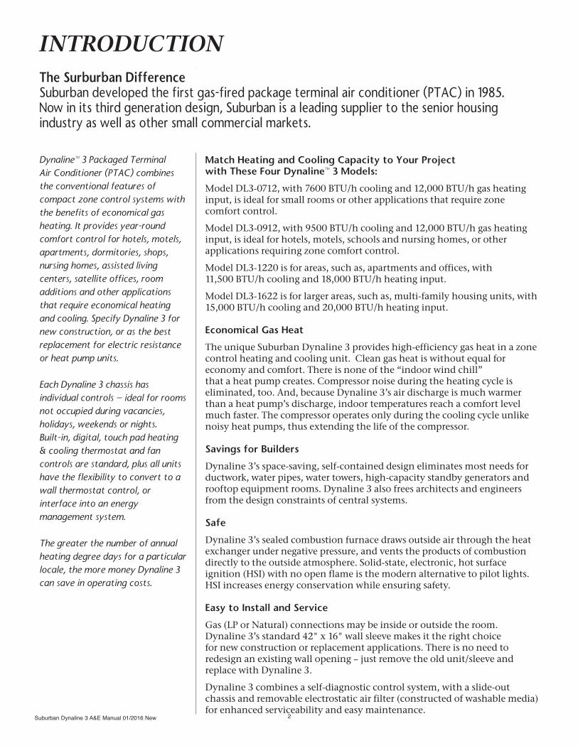
INTRODUCTION
Dynaline™ 3 Packaged Terminal Air Conditioner (PTAC) combines the conventional features of compact zone control systems with the benefits of economical gas heating. It provides year-round comfort control for hotels, motels, apartments, dormitories, shops, nursing homes, assisted living centers, satellite offices, room additions and other applications that require economical heating and cooling. Specify Dynaline 3 for new construction, or as the best replacement for electric resistance or heat pump units.
Each Dynaline 3 chassis has individual controls – ideal for rooms not occupied during vacancies, holidays, weekends or nights. Built-in, digital, touch pad heating & cooling thermostat and fan controls are standard, plus all units have the flexibility to convert to a wall thermostat control, or interface into an energy management system.
The greater the number of annual heating degree days for a particular locale, the more money Dynaline 3 can save in operating costs.
The Surburban DifferenceSuburban developed the first gas-fired package terminal air conditioner (PTAC) in 1985. Now in its third generation design, Suburban is a leading supplier to the senior housing industry as well as other small commercial markets.
Suburban Dynaline 3 A&E Manual 01/2016 New3
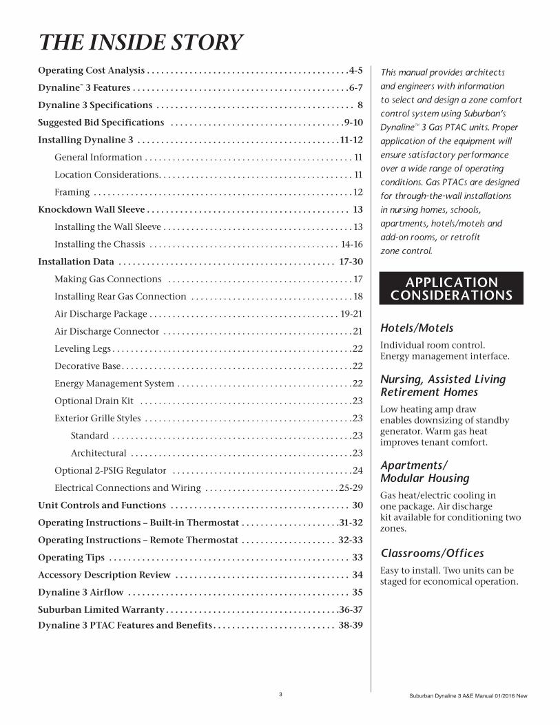
Operating Cost Analysis . . . . . . . . . . . . . . . . . . . . . . . . . . . . . . . . . . . . . . . . . . .4-5
Dynaline™ 3 Features . . . . . . . . . . . . . . . . . . . . . . . . . . . . . . . . . . . . . . . . . . . . . .6-7
Dynaline 3 Specifications . . . . . . . . . . . . . . . . . . . . . . . . . . . . . . . . . . . . . . . . . . 8
Suggested Bid Specifications . . . . . . . . . . . . . . . . . . . . . . . . . . . . . . . . . . . . .9-10
Installing Dynaline 3 . . . . . . . . . . . . . . . . . . . . . . . . . . . . . . . . . . . . . . . . . . .11-12
General Information . . . . . . . . . . . . . . . . . . . . . . . . . . . . . . . . . . . . . . . . . . . . . 11
Location Considerations . . . . . . . . . . . . . . . . . . . . . . . . . . . . . . . . . . . . . . . . . . 11
Framing . . . . . . . . . . . . . . . . . . . . . . . . . . . . . . . . . . . . . . . . . . . . . . . . . . . . . . . . 12
Knockdown Wall Sleeve . . . . . . . . . . . . . . . . . . . . . . . . . . . . . . . . . . . . . . . . . . . 13
Installing the Wall Sleeve . . . . . . . . . . . . . . . . . . . . . . . . . . . . . . . . . . . . . . . . . 13
Installing the Chassis . . . . . . . . . . . . . . . . . . . . . . . . . . . . . . . . . . . . . . . . . 14-16
Installation Data . . . . . . . . . . . . . . . . . . . . . . . . . . . . . . . . . . . . . . . . . . . . . . 17-30
Making Gas Connections . . . . . . . . . . . . . . . . . . . . . . . . . . . . . . . . . . . . . . . . 17
Installing Rear Gas Connection . . . . . . . . . . . . . . . . . . . . . . . . . . . . . . . . . . . 18
Air Discharge Package . . . . . . . . . . . . . . . . . . . . . . . . . . . . . . . . . . . . . . . . . 19-21
Air Discharge Connector . . . . . . . . . . . . . . . . . . . . . . . . . . . . . . . . . . . . . . . . . 21
Leveling Legs . . . . . . . . . . . . . . . . . . . . . . . . . . . . . . . . . . . . . . . . . . . . . . . . . . . .22
Decorative Base . . . . . . . . . . . . . . . . . . . . . . . . . . . . . . . . . . . . . . . . . . . . . . . . . .22
Energy Management System . . . . . . . . . . . . . . . . . . . . . . . . . . . . . . . . . . . . . .22
Optional Drain Kit . . . . . . . . . . . . . . . . . . . . . . . . . . . . . . . . . . . . . . . . . . . . . .23
Exterior Grille Styles . . . . . . . . . . . . . . . . . . . . . . . . . . . . . . . . . . . . . . . . . . . . .23
Standard . . . . . . . . . . . . . . . . . . . . . . . . . . . . . . . . . . . . . . . . . . . . . . . . . . . .23
Architectural . . . . . . . . . . . . . . . . . . . . . . . . . . . . . . . . . . . . . . . . . . . . . . . .23
Optional 2-PSIG Regulator . . . . . . . . . . . . . . . . . . . . . . . . . . . . . . . . . . . . . . .24
Electrical Connections and Wiring . . . . . . . . . . . . . . . . . . . . . . . . . . . . . 25-29
Unit Controls and Functions . . . . . . . . . . . . . . . . . . . . . . . . . . . . . . . . . . . . . . 30
Operating Instructions – Built-in Thermostat . . . . . . . . . . . . . . . . . . . . .31-32
Operating Instructions – Remote Thermostat . . . . . . . . . . . . . . . . . . . . 32-33
Operating Tips . . . . . . . . . . . . . . . . . . . . . . . . . . . . . . . . . . . . . . . . . . . . . . . . . . . 33
Accessory Description Review . . . . . . . . . . . . . . . . . . . . . . . . . . . . . . . . . . . . . 34
Dynaline 3 Airflow . . . . . . . . . . . . . . . . . . . . . . . . . . . . . . . . . . . . . . . . . . . . . . . 35
Suburban Limited Warranty . . . . . . . . . . . . . . . . . . . . . . . . . . . . . . . . . . . . .36-37
Dynaline 3 PTAC Features and Benefits . . . . . . . . . . . . . . . . . . . . . . . . . . 38-39
Hotels/MotelsIndividual room control. Energy management interface.
Nursing, Assisted Living Retirement HomesLow heating amp draw enables downsizing of standby generator. Warm gas heat improves tenant comfort.
Apartments/Modular HousingGas heat/electric cooling in one package. Air discharge kit available for conditioning two zones.
Classrooms/OfficesEasy to install. Two units can be staged for economical operation.
This manual provides architects and engineers with information to select and design a zone comfort control system using Suburban’s Dynaline™ 3 Gas PTAC units. Proper application of the equipment will ensure satisfactory performance over a wide range of operating conditions. Gas PTACs are designed for through-the-wall installations in nursing homes, schools, apartments, hotels/motels and add-on rooms, or retrofit zone control.
APPLICATIONCONSIDERATIONS
THE INSIDE STORY
Suburban Dynaline 3 A&E Manual 01/2016 New 4
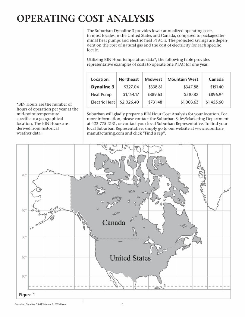
Location: Northeast Midwest Mountain West Canada
Dynaline 3 $327.04 $338.81 $347.88 $151.40
Heat Pump $1,154.17 $389.63 $510.82 $896.94
Electric Heat $2,026.40 $731.48 $1,003.63 $1,455.60
The Suburban Dynaline 3 provides lower annualized operating costs, in most locales in the United States and Canada, compared to packaged ter-minal heat pumps and electric heat PTAC’s. The projected savings are depen-dent on the cost of natural gas and the cost of electricity for each specific locale.
Utilizing BIN Hour temperature data*, the following table provides representative examples of costs to operate one PTAC for one year.
Suburban will gladly prepare a BIN Hour Cost Analysis for your location. For more information, please contact the Suburban Sales/Marketing Department at 423-775-2131, or contact your local Suburban Representative. To find your local Suburban Representative, simply go to our website at www.suburban-manufacturing.com and click “Find a rep”.
OPERATING COST ANALYSIS
Figure 1
*BIN Hours are the number of hours of operation per year at the mid-point temperature specific to a geographical location. The BIN Hours are derived from historical weather data.
Suburban Dynaline 3 A&E Manual 01/2016 New5
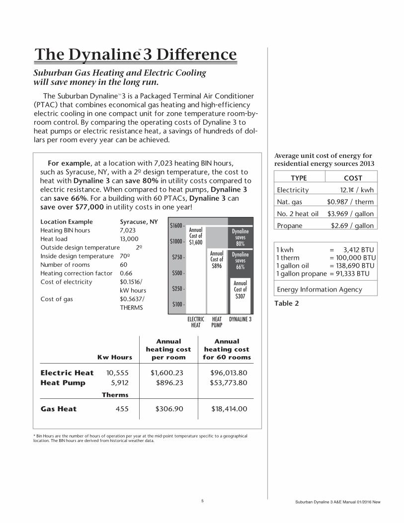
Average unit cost of energy for residential energy sources 2013
TYPE COST
Electricity 12.1¢ / kwh
Nat. gas $0.987 / therm
No. 2 heat oil $3.969 / gallon
Propane $2.69 / gallon
1 kwh = 3,412 BTU 1 therm = 100,000 BTU 1 gallon oil = 138,690 BTU 1 gallon propane = 91,333 BTU
Energy Information Agency
Table 2
Suburban Gas Heating and Electric Cooling will save money in the long run.
The Suburban Dynaline™3 is a Packaged Terminal Air Conditioner (PTAC) that combines economical gas heating and high-efficiency electric cooling in one compact unit for zone temperature room-by-room control. By comparing the operating costs of Dynaline 3 to heat pumps or electric resistance heat, a savings of hundreds of dol-lars per room every year can be achieved.
The Dynaline™ 3 Difference
* Bin Hours are the number of hours of operation per year at the mid-point temperature specific to a geographical location. The BIN hours are derived from historical weather data.
For example, at a location with 7,023 heating BIN hours, such as Syracuse, NY, with a 2º design temperature, the cost to heat with Dynaline 3 can save 80% in utility costs compared to electric resistance. When compared to heat pumps, Dynaline 3 can save 66%. For a building with 60 PTACs, Dynaline 3 can save over $77,000 in utility costs in one year!
Annual Annual heating cost heating cost Kw Hours per room for 60 rooms Electric Heat 10,555 $1,600.23 $96,013.80Heat Pump 5,912 $896.23 $53,773.80 Therms
Gas Heat 455 $306.90 $18,414.00
Location Example Syracuse, NYHeating BIN hours 7,023Heat load 13,000Outside design temperature 2ºInside design temperature 70ºNumber of rooms 60Heating correction factor 0.66Cost of electricity $0.1516/ kW hoursCost of gas $0.5637/ THERMS
HEATPUMP
DYNALINE 3
Dynalinesaves80%
Dynalinesaves66%
Annual Cost of$307
Annual Cost of$1,600
Annual Cost of$896
ELECTRIC HEAT
$1600 -
$1000 -
$750 -
$500 -
$250 -
$100 -
Suburban Dynaline 3 A&E Manual 01/2016 New 6
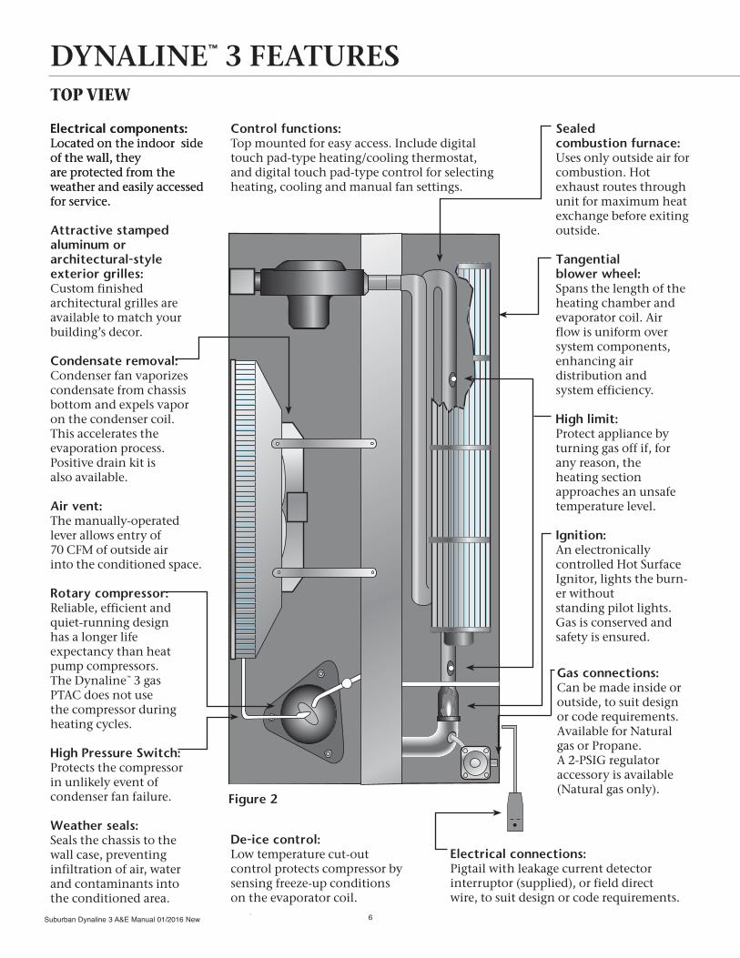
DYNALINE™ 3 FEATURESTOP VIEW
De-ice control:Low temperature cut-out control protects compressor by sensing freeze-up conditions on the evaporator coil.
Electrical components:Located on the indoor side of the wall, they are protected from the weather and easily accessed for service.
Attractive stamped aluminum or architectural-style exterior grilles:Custom finished architectural grilles are available to match your building’s decor.
Condensate removal:Condenser fan vaporizes condensate from chassis bottom and expels vapor on the condenser coil. This accelerates the evaporation process. Positive drain kit is also available.
Air vent:The manually-operated lever allows entry of 70 CFM of outside air into the conditioned space.
Rotary compressor:Reliable, efficient and quiet-running design has a longer life expectancy than heat pump compressors. The Dynaline™ 3 gas PTAC does not use the compressor during heating cycles.
High Pressure Switch:Protects the compressor in unlikely event of condenser fan failure.
Weather seals:Seals the chassis to the wall case, preventing infiltration of air, water and contaminants into the conditioned area.
Electrical components:Located on the indoor side of the wall, they are protected from the weather and easily accessed for service.
Sealed combustion furnace:Uses only outside air for combustion. Hot exhaust routes through unit for maximum heat exchange before exiting outside.
Tangential blower wheel:Spans the length of the heating chamber and evaporator coil. Air flow is uniform over system components, enhancing air distribution and system efficiency.
High limit:Protect appliance by turning gas off if, for any reason, the heating section approaches an unsafe temperature level.
Ignition:An electronically controlled Hot Surface Ignitor, lights the burn-er without standing pilot lights. Gas is conserved and safety is ensured.
Gas connections:Can be made inside or outside, to suit design or code requirements. Available for Natural gas or Propane. A 2-PSIG regulator accessory is available (Natural gas only).
Control functions:Top mounted for easy access. Include digital touch pad-type heating/cooling thermostat, and digital touch pad-type control for selecting heating, cooling and manual fan settings.
Figure 2
Electrical connections:Pigtail with leakage current detector interruptor (supplied), or field direct wire, to suit design or code requirements.

Suburban Dynaline 3 A&E Manual 01/2016 New7
40
14 9—32
21
14 7—8
1—167
25—32
42
7
14
42
16
16
42
11—16
40 5—8
3—8
143—4
Copper and aluminum evaporator and condenser coils:For extended life and ease of repair. Coils use seamless copper tubing, mechanically expanded into aluminum plate fins.
Compressor lock-out:Standard design provides means of lock-ing out A/C compressor when standby power generator is operating. Electronic control board has 24V input terminals to receive lock-out signal.
Room air discharge: Attractive, durable grille constructed of extruded aluminum, 52° off vertical air discharge pattern.
Return air filter:No tools are needed to install or remove the permanent electrostatic filter constructed of washable media.
END VIEW (LH)
UNIT WALL SLEEVE DIMENSIONS
Figure 4
Figure 3
Specifications subject to change without notice.

Suburban Dynaline 3 A&E Manual 01/2016 New 8
SPECIFICATIONS DYNALINE™ 3 SERIESGeneral Data DL3-1622 DL3-1220 DL3-091 DL3-0712
Rated heating input (BTU/h) 20,000 18,000 12,000 12,000Rated heating output (BTU/h) 16,000 14,580 9,840 9,840Steady state efficiency 80% 81% 82% 82%Rated cooling capacity (BTU/h) 15,000 11,500 9,500 7,600Sensible/Latent cooling 65/35 65/35 69/31 65/35EER 9.5 10.4 11.2 11.6Rated air flow: fan only (CFM)
Hi cool/low cool (CFM)Hi heat/low heat (CFM)
340400/330420/340
300390/300410/300
260300/250320/260
260300/250320/260
Weight (Lbs.) 185 180 180 180Cabinet Color Champagne Beige
Minimum Installation ClearancesOutside:*
Rear to nearest obstructionTop, sides to nearest obstruction Centerline vent to window
3 feet
09"
3 feet
09"
3 feet
09"
3 feet
09"
Inside:Front to nearest obstructionSides to nearest obstruction
Bottom to floor(for return air)Cabinet top to ceiling
12"**1"
012"
12"**1"
012"
12"**1"
012"
12"**1"
012"
* Clearance to ground should be noted (see installation manual).** Obstruction must be removable for service of unit.
Electrical DataVolts/Phase/Cycle 208/230-1-60Min. wire size (Copper) #14 AWG #14 AWG #14 AWG #14 AWGProtection-Fused 2-15 amp 2-15 amp 2-15 amp 2-15 ampProtection-Circuit (HACR type) Dual - 15 ampUnit Plug:
AmpsNEMA Rating
15 amp6-15 P
15 amp6-15 P
15 amp6-15 P
15 amp6-15 P
Receptacle:TypeAmpsNEMA Rating
Tandem15 amp6-15 R
Tandem15 amp6-15 R
Tandem15 amp6-15 R
Tandem15 amp6-15 R
Total amps cooling/heating 7.5/1.2 5.1/1.0 3.8/1.0 3.3/1.0Total watts cooling/heating 1550/260 1125/150 855/150 675/150
CompressorType Hermetic RotaryRefrigerant type (HCFC) R410-A R410-A R410-A R410-ARefrigerant charge 36 oz. 32 oz. 26 oz. 28 oz.Rated Load amps 6.6 5.1 3.9 2.9Locked rotor Amps 32 25 22 15Rated capacity (BTU/h) 14,100 10,300 8,050 6,600
Compressor lock-out relay (Normally closed 24V) 5VA enrush - 4V constant
Specifications subject to change without notice.
Condenser Fan DL3-1622 DL3-1220 DL3-091 DL3-0712Fan blade diameter 12" 12" 12" 12"Number of blades 4 4 4 4Pitch 25º 25º 25º 25ºCondenser fan motor RPM 1,500 1,500 1,500 1,500Full load amps 0.5 0.5 0.5 0.5
Condenser CoilType Copper/AluminumCoil Area 364 sq. inchesRows 3 3 3 3Fins per inch 13 13 12 12
Evaporator CoilType Copper/AluminumCoil Area 260 sq. in. 260 sq. in. 234 sq. in. 234 sq. in.Rows 3 3 3 3Fins per inch 11 11 11 11Refrigerant metering Capillary
Room Air Fan MotorSpeed 2 2 2 2RPM high/low 1500/1250 1520/1400 1260/1130 1260/1130Full load amps 0.7 0.5 0.3 0.3Min. wire size (60º copper) #18 AWG #18 AWG #18 AWG #18 AWG
Gas Controls and General DataGas (specify) Natural or LPBurners 1 1 1 1Ignition system: Solid-state Hot surfaceHigh limit (fixed) 220º 220º 220º 220ºBlocked flue switch 205º 200º 200º 200ºGas connection size 3/8" IPS 3/8" IPS 3/8" IPS 3/8" IPSGas connection (LH) front or rear
Blower/EvaporatorWheel diameter 4.53" 4.53" 4.375" 4.375"Wheel width 26" 26" 26" 26"Air vent-manual 70 CFM 70 CFM 70 CFM 70 CFMRequired filter (1 each) 8-1/4"x30-3/4" 6"x30-3/4" 6"x30-3/4" 6"x30-3/4"Filter type Electrostatic/washable media

Suburban Dynaline 3 A&E Manual 01/2016 New9
The supplier will provide packaged terminal gas heat/electric air conditioner of the sizes and capacities shown on the schedule and listed in the specifications. Each unit shall consist of a chassis, wall case/sleeve, outside grille and room cabinet. Units shall be UL listed and/or ETL design certified and shall be Suburban Manufacturing Company DYNALINE™ 3 models, or equivalents. The units shall be located as shown on the drawings.
Unit’s steady state efficiency shall be rated at 80% nominal and the EER of the air conditioner shall not be less than ASHRAE 90.1 - 2010 standards.
Units shall be designed to operate on 208/230 volts, 60 Hz, single phase power.
Unit dimensions shall not exceed 42" wide and 16" high without optional air discharge package in place, and not more than 22-29/32" from face of room cabinet to face of standard exterior grille.
Units shall be designed to operate on Natural or LP gas for the heating cycle.
CHASSIS: Unit chassis shall be a standard product of the manufacturer and shall be packed to prevent damages when reasonable care is exercised during shipment. Warnings on packaging shall alert handlers to the hazards of improper handling or stacking.
Chassis shall slide into a standard-sized wall case and, after installation and testing, be ready to operate. Each chassis shall consist of the following system and components:
• Refrigeration system constructed to isolate the hermetically sealed rotary-type compressor from external vibration. The system shall include copper/aluminum condenser and evaporator coils with capillary refrigerant control.
• Air flow system consists of a two-speed room air motor (for Hi & Low A/C and Hi & Low heat speeds) and a fan cycle switch to permit continuous indoor fan operation. A separate condenser fan operates in the A/C cycle only. The condenser fan, not operating in the heating mode, eliminates the potential for exhaust gases to be drawn back and freezing in the chassis compartment. The room air system incorporates a tangential blower wheel for reduced noise and increased efficiency.
• Condenser coils, with not less than 13 fins per inch, and evaporator coils, with not less than 11 fins per inch. Coils shall be constructed of copper/aluminum and fins shall be bonded to tubes to prevent electrolytic action.
• Indoor and outdoor airflow which match the coil capacity for efficient transfer of heat. Design of the unit shall prevent water blow-off on the indoor evaporator coil. Indoor supply air grille, constructed of extruded aluminum, shall discharge air at 52 degrees off vertical pattern.
• Electrostatic return air filter, constructed of washable media, that installs and removes without tools.
• Factory-installed, gas-fired heat exchanger with electronic controlled, pilotless ignition system and a “draw-through” negative draft combustion air system. Gas ignition shall occur by energizing hot surface ignitor, which lights the burner on each thermostatically controlled heating cycle. Heat exchanger shall be located in indoor air stream so as not to be visible or accessible through indoor supply air grille.
SUGGESTED BID SPECIFICATIONSFOR PRODUCT AND APPLICATION

Suburban Dynaline 3 A&E Manual 01/2016 New 10
• Touch pad-type digital control for selecting temperature set point, heating, cooling and manual fan operation. Control system to incorporate computerized self-diagnostics to facilitate troubleshooting.
• Positive closing fresh air damper, located within the chassis. An accessible manual control shall operate the damper.
• Compressor “lock-out” interface with standby emergency power generator.
WALL CASE: Wall case shall be constructed of 18-gauge galvanized and shall have a protective baked-on enamel finish. Base pan shall be 18-gauge galvanized. Cases shall be installed through exterior walls where shown on the plans and shall be level from side to side and slope 1/4" from front to rear to ensure proper operation of condensate system. Case shall be secured to the wall at both sides as shown in installation instructions. In no instance shall fasteners be used through the base pan so as to protect the water integrity of the base pan.
OUTSIDE GRILLE: Special grilles to be supplied by others must be submitted to the PTAC manufacturer for feasibility and air flow characteristics.
ROOM CABINET: Each room chassis shall be equipped with a removable, wrap-around room cabinet constructed of 20-gauge galvanized steel with a protective baked-on enamel finish similar to the wall case.
GAS TYPE: Natural gas units shall be equipped with a gas valve having a built-in regulator set to operate at the gas inlet supply pressure, minimum 5" W.C., maximum 7" W.C. Units burning LP gas shall be equipped with a gas valve having a built-in regulator set to operate at gas inlet supply pressures of 11" W.C. minimum and 13" W.C. maximum.
SERVICE: Bidders shall submit complete information regarding service availability, including address(es) and phone number(s), along with complete information of manufacturer address and phone number to cover service information pertinent to installed equipment.
RESPONSIBILITY FOR INSTALLATION, START-UP, TESTING, DEMONSTRATION: Units shall be installed in full accordance to the manufacturer’s recommendation. The manufacturer shall not be liable for unit failure resulting from improper installation, which invalidates the warranty. Bidders shall specify their responsibilities for the initial starting of units, performing necessary tests and adjustments to place units in proper operating condition and demonstrating heating and cooling operations to the owner or the owner’s representative.
WARRANTY: There shall be a one-year limited warranty on parts and labor and a five-year limited warranty on the compressor and heat exchanger.
SUGGESTED BID SPECIFICATIONSFOR PRODUCT AND APPLICATION
Suburban Dynaline 3 A&E Manual 01/2016 New11
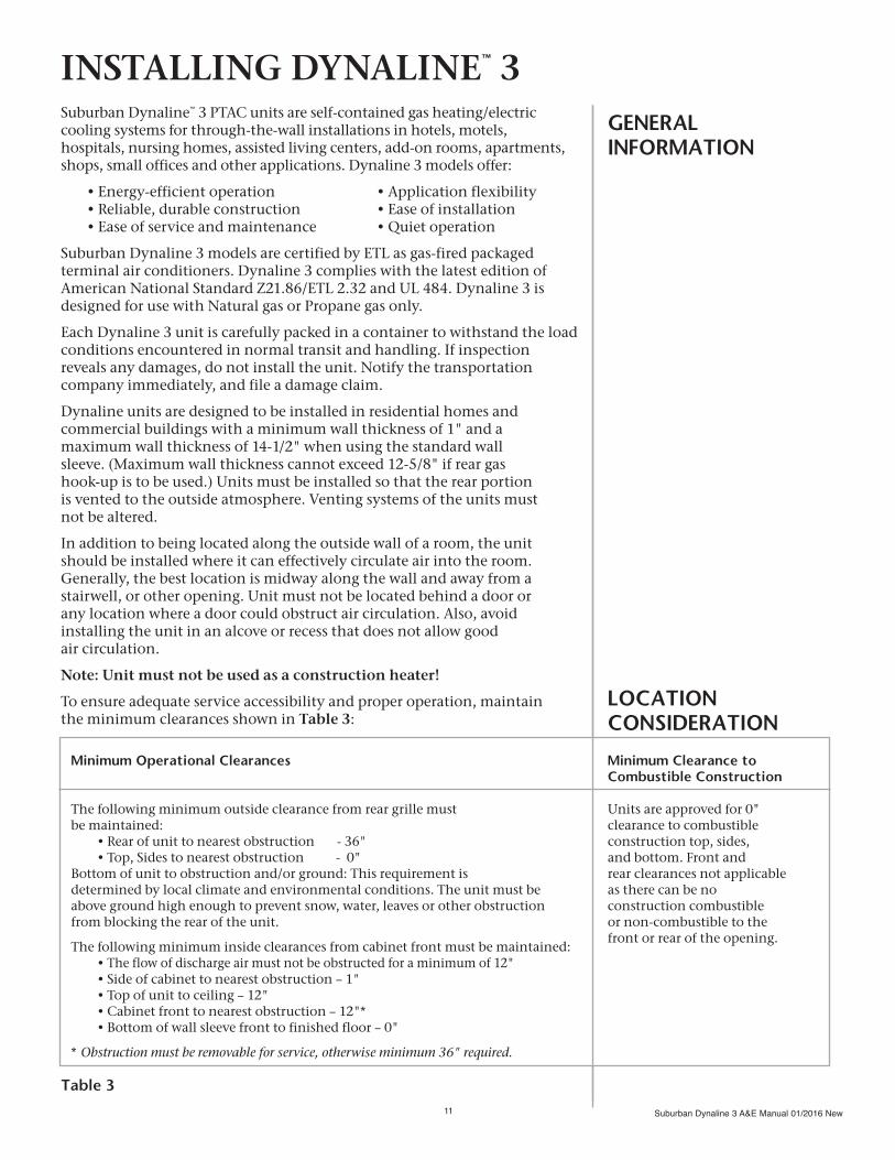
Suburban Dynaline™ 3 PTAC units are self-contained gas heating/electric cooling systems for through-the-wall installations in hotels, motels, hospitals, nursing homes, assisted living centers, add-on rooms, apartments, shops, small offices and other applications. Dynaline 3 models offer:
• Energy-efficient operation • Application flexibility • Reliable, durable construction • Ease of installation • Ease of service and maintenance • Quiet operation
Suburban Dynaline 3 models are certified by ETL as gas-fired packaged terminal air conditioners. Dynaline 3 complies with the latest edition of American National Standard Z21.86/ETL 2.32 and UL 484. Dynaline 3 is designed for use with Natural gas or Propane gas only.
Each Dynaline 3 unit is carefully packed in a container to withstand the load conditions encountered in normal transit and handling. If inspection reveals any damages, do not install the unit. Notify the transportation company immediately, and file a damage claim.
Dynaline units are designed to be installed in residential homes and commercial buildings with a minimum wall thickness of 1" and a maximum wall thickness of 14-1/2" when using the standard wall sleeve. (Maximum wall thickness cannot exceed 12-5/8" if rear gas hook-up is to be used.) Units must be installed so that the rear portion is vented to the outside atmosphere. Venting systems of the units must not be altered.
In addition to being located along the outside wall of a room, the unit should be installed where it can effectively circulate air into the room. Generally, the best location is midway along the wall and away from a stairwell, or other opening. Unit must not be located behind a door or any location where a door could obstruct air circulation. Also, avoid installing the unit in an alcove or recess that does not allow good air circulation.
Note: Unit must not be used as a construction heater!
To ensure adequate service accessibility and proper operation, maintain the minimum clearances shown in Table 3:
GENERAL INFORMATION
INSTALLING DYNALINE™ 3
Minimum Operational Clearances
The following minimum outside clearance from rear grille must be maintained: • Rear of unit to nearest obstruction - 36" • Top, Sides to nearest obstruction - 0"Bottom of unit to obstruction and/or ground: This requirement is determined by local climate and environmental conditions. The unit must be above ground high enough to prevent snow, water, leaves or other obstruction from blocking the rear of the unit.
The following minimum inside clearances from cabinet front must be maintained: • The flow of discharge air must not be obstructed for a minimum of 12" • Side of cabinet to nearest obstruction – 1" • Top of unit to ceiling – 12" • Cabinet front to nearest obstruction – 12"* • Bottom of wall sleeve front to finished floor – 0"
* Obstruction must be removable for service, otherwise minimum 36" required.
LOCATIONCONSIDERATION
Minimum Clearance toCombustible Construction
Units are approved for 0" clearance to combustible construction top, sides, and bottom. Front and rear clearances not applicable as there can be no construction combustible or non-combustible to the front or rear of the opening.
Table 3
Suburban Dynaline 3 A&E Manual 01/2016 New 12
HEADER(STEEL LINTEL IN BRICK CONSTRUCTION)
FINISHED FLOORSUB-FLOOR
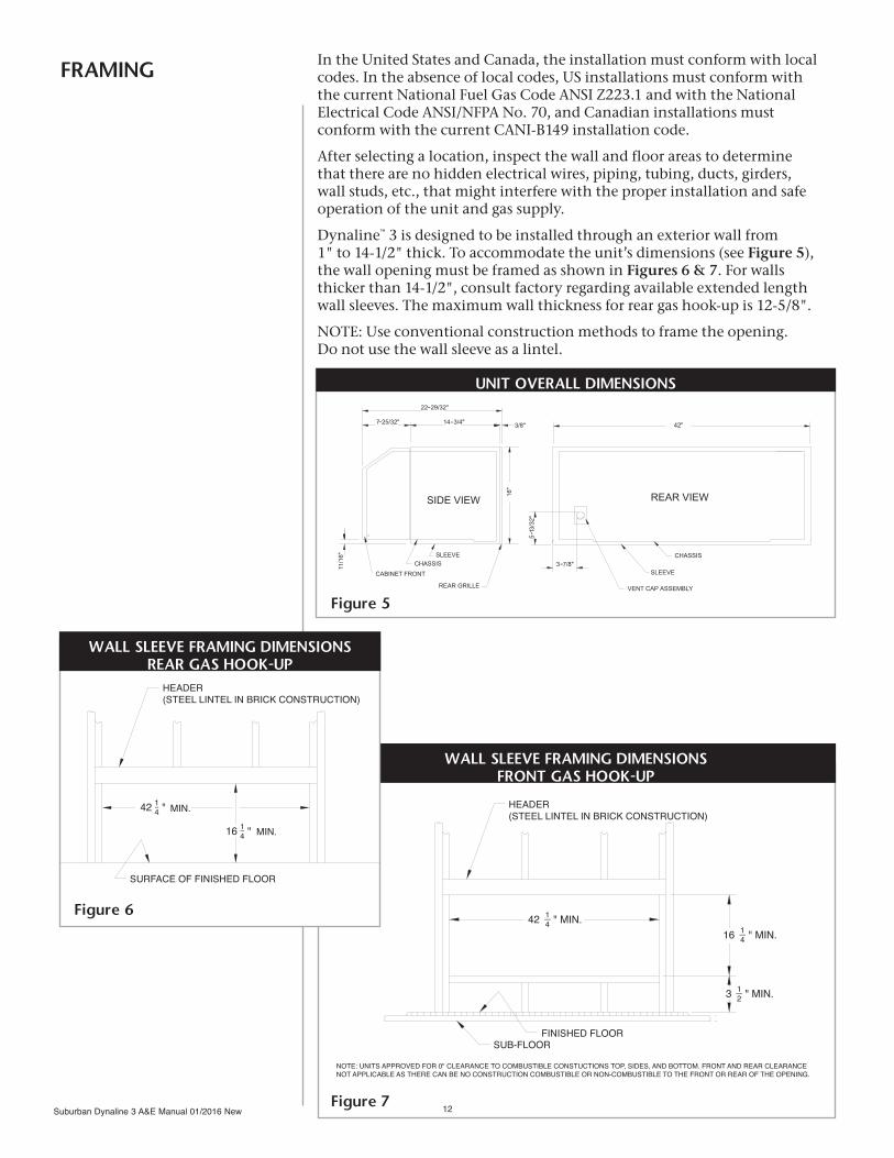
NOTE: UNITS APPROVED FOR 0" CLEARANCE TO COMBUSTIBLE CONSTUCTIONS TOP, SIDES, AND BOTTOM. FRONT AND REAR CLEARANCENOT APPLICABLE AS THERE CAN BE NO CONSTRUCTION COMBUSTIBLE OR NON-COMBUSTIBLE TO THE FRONT OR REAR OF THE OPENING.
42 1—4 " MIN.16 1—4 " MIN.
3 1—2 " MIN.
FRAMING In the United States and Canada, the installation must conform with local codes. In the absence of local codes, US installations must conform with the current National Fuel Gas Code ANSI Z223.1 and with the National Electrical Code ANSI/NFPA No. 70, and Canadian installations must conform with the current CANI-B149 installation code.
After selecting a location, inspect the wall and floor areas to determine that there are no hidden electrical wires, piping, tubing, ducts, girders, wall studs, etc., that might interfere with the proper installation and safe operation of the unit and gas supply.
Dynaline™ 3 is designed to be installed through an exterior wall from 1" to 14-1/2" thick. To accommodate the unit’s dimensions (see Figure 5), the wall opening must be framed as shown in Figures 6 & 7. For walls thicker than 14-1/2", consult factory regarding available extended length wall sleeves. The maximum wall thickness for rear gas hook-up is 12-5/8".
NOTE: Use conventional construction methods to frame the opening. Do not use the wall sleeve as a lintel.
Figure 5
Figure 7
UNIT OVERALL DIMENSIONS
WALL SLEEVE FRAMING DIMENSIONSFRONT GAS HOOK-UP
MIN.
1—4 MIN.
HEADER(STEEL LINTEL IN BRICK CONSTRUCTION)
SURFACE OF FINISHED FLOOR
42 1—4 "
16 "
Figure 6
WALL SLEEVE FRAMING DIMENSIONSREAR GAS HOOK-UP

Suburban Dynaline 3 A&E Manual 01/2016 New13
1. Unfold the sides of the wall sleeve and assemble the top, so that the sides wedge between the top flange and the retaining angle. (See Figure 8.) Apply 4 screws provided to secure top to the sides.
2. Cut an opening in the outside wall and frame to minimum opening. (See Figures 6 & 7.)
3. Install wall sleeve into framed opening. Be sure that the bottom of wall sleeve is resting firmly on the bottom framing member since the weight of the unit rests solely on the bottom of the wall sleeve. Failure to support the bottom of the wall sleeve could pull the sides away and result in water leakage on the floor.
4. Secure the wall sleeve to the wall as shown in Figures 9 & 10. Be sure wall sleeve has a 1/4" slope to the outside. Do not slope toward front! To avoid water damage to the wall, do not put holes through the bottom of the wall sleeve.
NOTE: If the unit is to be mounted flush with the exterior wall, wall sleeve must protrude beyond the finished exterior wall a minimum of 1/4". If rear gas connection, sleeve must extend beyond the finished exterior wall surface 1-5/8”. (See Figures 9, 10, & 11.)
5. Trim around the wall sleeve with moulding or other suitable material. (See Figures 9, 10, & 11.)
6. Install the grille with louvers angled in the downward position, as shown in Figures 9, 10 & 11.
NOTE: Outside rear grille must be installed prior to installing chassis.
NOTE: Do not discard packing inside carton. It may be used as a temporary cover for weather and construction protection. To cover the wall sleeve opening, cut cardboard insert along the perforated line, fold and place in rear of sleeve.
INSTALLING THEWALL SLEEVE
KNOCKDOWN WALL SLEEVE
Figure 8

Suburban Dynaline 3 A&E Manual 01/2016 New 14
SLOPE DOWN TO THE OUTSIDE
SURFACE OF FINISHEDFLOOR OR TOP OF CARPET
MIN. (PROJECTION BEYOND EXTERIOR WALL)
Y"
X"
MOUNTING HOLES AND SCREWS(BY INSTALLER.)DO NOT PUT HOLES THROUGHWALL SLEEVE BOTTOM!
REAR GRILLE
CAULK AROUND WALL SLEEVESURFACE OF FINISHED EXTERIOR WALL
Y" = - ( X" + )
SURFACE OF FINISHED INTERIOR WALL
CABINET FRONT
X" REPRESENTS EITHER THE DIMENSION REQUIRED TO FLUSH SLEEVE TO FINISHED TRIM OR MOLDING, OR THE DISTANCE SLEEVE PROJECTS INTO ROOM BEYOND FINISHED INTERIOR WALL.NOTE: X" CAN BE 0" IF SLEEVE IS FLUSH WITH FINISHED INTERIOR WALL.
1 5—8 "
1—4
"
1 5—8"14 3—4"
INSTALLING THE CHASSIS
1. Slide chassis squarely into wall sleeve from inside and secure with four (4) screws into flange on wall sleeve to ensure proper security.
2. Connect gas and electrical supply. (See pages 13, 14 and 20.)
3. Remote thermostat: Dynaline™ 3 chassis are supplied for standard built-in control. To convert the standard chassis to function with remote thermostat, connect the thermostat wiring (according to thermostat manufacturer’s instructions) to the terminal block located on the module board. Move the dip switch #1 on the module board to the “ON” position. (See Figure 12.) Unit is capable of operating set-back (5-wire) thermostat.
NOTE: Connecting remote thermostat overrides the built-in thermostat and no digital read out will be displayed on the control panel. There is no need to disconnect the chassis’ built-in thermostat.
4. To lock out the A/C compressor when the chassis is powered by an emergency standby power generator, 24-volt lead wires from the transformer (NOTE: Field supplied transformer to be powered by the standby generator) must be connected to the 1/4" spade terminals on the module board. (See Figure 27 for ladder diagram of typical standby generator electric service.)
5. Install cabinet front.
Figure 9
WALL INSTALLATIONREAR GAS HOOK-UP

Suburban Dynaline 3 A&E Manual 01/2016 New15
X" REPRESENTS EITHER THE DIMENSION REQUIRED TO FLUSH SLEEVE TO FINISHED TRIM OR MOLDING, OR THE DISTANCE SLEEVE PROJECTS INTO ROOM BEYOND FINISHED INTERIOR WALL.NOTE: X" CAN BE 0" IF SLEEVE IS FLUSH WITH FINISHED INTERIOR WALL.
SURFACE OF FINISHED INTERIOR WALL
CABINET FRONT
SLOPE DOWN TO THE OUTSIDE
MIN. (PROJECTION BEYOND EXTERIOR WALL)
MOUNTING HOLES AND SCREWS(BY INSTALLER.)DO NOT PUT HOLES THROUGHWALL SLEEVE BOTTOM!
REAR GRILLE
CAULK AROUND WALL SLEEVESURFACE OF FINISHED EXTERIOR WALL
3 (MIN.)21"
Y"
X"
Y" = 14 - ( X" + )3"4
1"4
1"4
1"4
SURFACE OF FINISHEDFLOOR OR TOP OF CARPET
SLOPE DOWN TO THE OUTSIDE
SURFACE OF FINISHEDFLOOR OR TOP OF CARPET
MIN. (PROJECTION BEYOND WALL)
WALL SLEEVE ANGLES & SCREWS(BY INSTALLER.)DO NOT PUT HOLES THROUGH OR DRIVESCREWS INTO WALL SLEEVE BOTTOM!
CAULK AROUND WALL SLEEVEWINDOW OR WALL
CABINET FRONT
WALL SLEEVE(MAX.) LONG SCREWS FOR SECURINGANGLES TO TOP & SIDES OF SLEEVE.
2 (MIN.) SUPPORTS(BY INSTALLER)
REAR GRILLE
1"2
3 (MIN.)1"2 1"
4
1"4
Figure 10
Figure 11
WALL INSTALLATIONFRONT GAS HOOK-UP
WINDOW, CURTAIN WALL, ORWALL PANEL INSTALLATION

Suburban Dynaline 3 A&E Manual 01/2016 New 16
Figure 12

Suburban Dynaline 3 A&E Manual 01/2016 New17
Dynaline™ 3 chassis are factory equipped with a 3/8" NPT gas connection located at the bottom left front corner. Gas piping used to make the gas connection to the unit must be purchased locally. The size of the pipe should be computed according to type of gas and length of run. (See Table 5.) See Figure 13 for location of gas connection on the chassis when installed into the wall sleeve.
Table 5 gives a reasonably accurate size for the gas service line. The quantities in the table are for cubic feet per hour. To convert BTU capacity to cubic feet, divide total BTU load by the BTU value of the gas being used. The table is for Natural gas only. To convert to Propane gas, multiply by .633.
The pressure drop caused by other gas appliances being served must be considered. If the new line is a take-off from an existing line to another appliance, pressure drop computation with the table must include the demand of the other appliance.
Gas supply pressure for purposes of input adjustment
Minimum Maximum
Natural Gas 5" Water Column 7" Water Column
Propane Gas 11" Water Column 13" Water ColumnTable 4
Length of pipe 1/2 3/4 1 1-1/4 1-1/2 in feet 10 132 278 520 1,050 1,600 20 92 190 350 730 1,100 30 73 152 285 590 890 40 63 130 245 500 760 50 56 115 215 440 670 60 50 105 195 400 610 70 46 96 180 370 560 80 43 90 170 350 530 90 40 84 160 320 490 100 38 79 150 305 460 125 34 72 130 275 410 150 31 64 120 250 380 175 28 59 110 225 350 200 26 55 100 210 320
MAKING GASCONNECTIONS
Iron Pipe Sizes (IPS) Inches
INSTALLATION DATA
Table 5
Capacity of pipe of different diameters and lengths in cubic feet per hour with pressure drop of 0.3 inches and specific gravity of 0.60 inches.
All units are equipped with a valve having a built-in regulator. For units burning Natural gas, the regulator is preset at 3.5" W.C. pressure. For units burning LP gas, the regulator is preset at 10.5" W.C. pressure.
It is recommended that a shut-off valve be installed in the gas line to the unit, and that a ground joint union also be installed.
NOTE: Manual shut-off valve to be supplied by installer.
A condensate trap should also be installed in the gas supply line as close to the unit as possible.
To occasionally monitor the gas supply pressure to the unit, install a 1/8" NPT plug tap for test gauge connection immediately upstream of the gas supply connection to the unit. The unit must be disconnected from the gas supply piping system during any pressure testing of the gas supply system at test pressures equal to or greater than 1/2 PSIG.
Figure 13
Operating Pressure
Suburban Dynaline 3 A&E Manual 01/2016 New 18
INSTALLING REAR GAS CONNECTION WITH REAR GAS HOOK-UP KIT
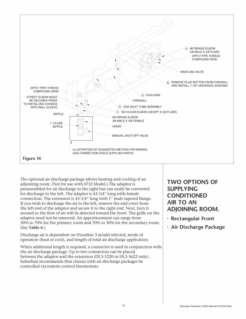
Dynaline™ 3 chassis are manufactured for front gas hook-up. The optional rear gas hook-up kit can be used for field conversion of the chassis to a rear gas hook-up at the RH side (facing back of the unit).
1. Remove cabinet front.
2. Remove brass street elbow from valve and replace it with the 3/8" NPT x 3/8" flare elbow provided. Be sure to apply a thread compound resistant to the action of liquefied petroleum (LP) gas and Natural gas to the threads. NOTE: Flared portion of elbow must be pointing up. Do not discard the elbow that was removed. It will be used later. (See A, Figure 14.)
3. Remove the 1-1/8" plug from the firewall and replace it with the 1-1/8" universal bushing provided. (See B, Figure 14.)
4. Using the two (2) 8-32 x 1/2 self tapping screws provided, secure hi-ear elbow as illustrated. (See C, Figure 14.)
5. Insert gas inlet tube assembly. (See D, Figure 14) through bushing in firewall. NOTE: The shortest end of the tube connects to main gas valve.
6. Secure tube assembly to elbows as illustrated. (See Figure 14.) Do not apply thread compound to flare fittings.
7. Using silicone caulking, seal gas inlet tube assembly where it passes through bushing. (See E, Figure 14.)
8. Install street elbow removed from valve in Step #2. Clean threads, and apply new thread compound sealant. Secure street elbow to the 90° hi-ear elbow that was attached to chassis in Step #4. Female threads must be pointing down.
9. Install chassis into wall sleeve.
10. Chassis installation into wall case can now be completed by installing nipple, union and shutoff valve (field supplied) in accordance with local code.
11. Check all joints for gas leaks.
NOTE: Wall sleeve must extend beyond the finished exterior wall surface 1-5/8" minimum.
Suburban Dynaline 3 A&E Manual 01/2016 New19
MAIN GAS VALVE
90ϒ BRASS ELBOW3/8 MALE X 3/8 FLARE
FIREWALL
GAS INLET TUBE ASSEMBLY
90ϒ BRASS ELBOW3/8 MALE X 3/8 FEMALE
NIPPLE
UNION1" CLOSE
NIPPLE
MANUAL SHUT-OFF VALVE
ILLUSTRATION OF SUGGESTED METHOD FOR MAKINGGAS CONNECTION (FIELD SUPPLIED PARTS)
CAULKING
90ϒ HI-EAR ELBOW (3/8 NPT X 3/8 FLARE)
APPLY PIPE THREADCOMPOUND HERE
APPLY PIPE THREADCOMPOUND HERE
STREET ELBOW MUST BE SECURED PRIOR
TO INSTALLING CHASSIS INTO WALL SLEEVE
A
B
E
D
C
REMOVE PLUG BUTTON FROM FIREWALLAND INSTALL 1-1/8" UNIVERSAL BUSHING
TWO OPTIONS OF SUPPLYING CONDITIONED AIR TO AN ADJOINING ROOM.
• Rectangular Front
• Air Discharge Package
The optional air discharge package allows heating and cooling of an adjoining room. (Not for use with 0712 Model.) The adaptor is preassembled for air discharge to the right but can easily be converted for discharge to the left. The adaptor is 43-1/4" long with female connection. The extension is 43-1/4" long with 1" male tapered flange. If you wish to discharge the air to the left, remove the end cover from the left end of the adaptor and secure it to the right end. Next, turn it around so the flow of air will be directed toward the front. The grille on the adaptor need not be removed. Air apportionment can range from 30% to 70% for the primary room and 70% to 30% for the secondary room. (See Table 6.)
Discharge air is dependent on Dynaline 3 model selected, mode of operation (heat or cool), and length of total air discharge application.
When additional length is required, a connector is used in conjunction with the air discharge package. Up to two connectors can be placedbetween the adaptor and the extension (DL3-1220 or DL3-1622 only). Suburban recommends that chassis with air discharge packages be controlled via remote control thermostats.
Figure 14

Suburban Dynaline 3 A&E Manual 01/2016 New 20
DL3-1220/DL3-1622 DL3-0912** 1* 2 3 3 HI LOW HI LOW HI LOW HI LOW 50/50 143/121 127/108 50/50 144/122 128/108 50/50 145/123 129/109 50/50 123/104 109/93 60/40 159/102 142/91 60/40 160/103 143/91 60/40 161/103 143/92 60/40 137/88 122/78 70/30 173/85 154/76 70/30 174/84 155/76 70/30 175/86 156/77 70/30 149/73 132/65
Installation when adaptor support brackets are mounted to finished wall.
NOTE: Projection of wall sleeve into room cannot exceed 1-1/4".
1. Mount adaptor brackets to the wall as illustrated. Installer to provide screws. (See Figure 17.) 2. Slide collar into position under the adaptor and secure
with the two (2) screws provided. (See Figure 16.) 3. If the required air flow direction is to the left, remove the end cap and three (3) tinnermans from the left end of the adaptor. Reinstall end cap and tinnermans to the right end of the adaptor. 4. Remove the center section from the cabinet front assembly. (See Figure 15.) If the center section is not removed, you will be unable to open the cabinet front once the collar and adaptor are installed. Discard center section. 5. Remove the discharge air grille from the unit. Retain the two (2) screws. 6. Place the adaptor and collar assembly into position on the unit. Make sure the adaptor is resting on the adaptor brackets – adjust brackets as needed! 7. Locate the hole in the adaptor bracket and mark the underside of the adaptor at each end. 8. Remove adaptor and collar assembly from unit. At the two (2) locations marked on the adaptor in Step #7, drill a 7/64"-diameter hole (2 places). 9. Install adaptor and collar assembly on unit as illustrated and secure with the two (2) screws retained in Step #5. Also, secure the adaptor to the adaptor brackets with the screws provided.
10. Install the extension (DL3-0912) or the connector(s) and extension (DL3-1220 or DL3-1622 only) as required. Installer must provide wall support brackets for the connectors and extension. 11. Air Delivery: The air delivery baffle, located under the discharge air grille in the adaptor, is factory positioned to provide a 50/50 distribution of air into each zone. By removing the baffle and cutting along the scored line, 60% of the conditioned air will flow in the primary zone. Removing the baffle results in a 70/30 split. (On model DL3-1622 you must remove the baffle). For best results unit should be run on Hi only when using discharge package.
CFM CHART (DRY COIL)
** DL3-0912 - 1 and 2 are N/A. There is only one
extension or connector allowed for DL3-0912
INSTALLING AIR DISCHARGE PACKAGE
Figure 16
Figure 15
* Max. length = 130" from adaptor.
1
2
3
A
A
A B
B
B
Table 6
Suburban Dynaline 3 A&E Manual 01/2016 New21
AIR DISCHARGE CONNECTOR
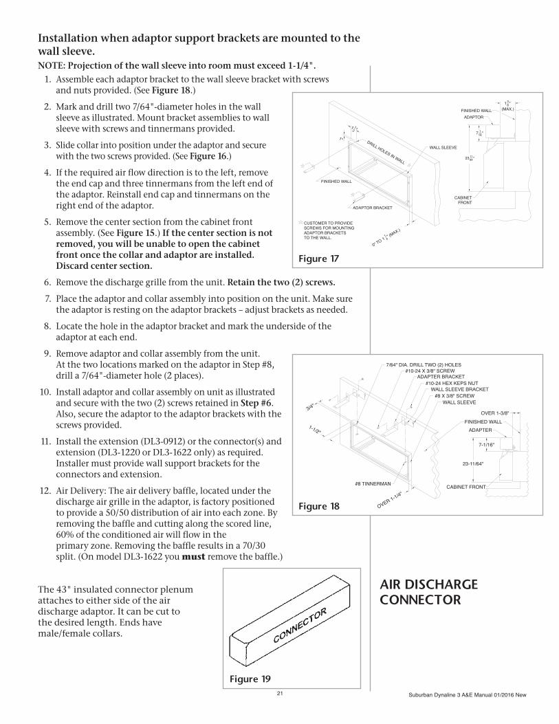
Installation when adaptor support brackets are mounted to the wall sleeve.NOTE: Projection of the wall sleeve into room must exceed 1-1/4". 1. Assemble each adaptor bracket to the wall sleeve bracket with screws and nuts provided. (See Figure 18.)
2. Mark and drill two 7/64"-diameter holes in the wall sleeve as illustrated. Mount bracket assemblies to wall sleeve with screws and tinnermans provided.
3. Slide collar into position under the adaptor and secure with the two screws provided. (See Figure 16.)
4. If the required air flow direction is to the left, remove the end cap and three tinnermans from the left end of the adaptor. Reinstall end cap and tinnermans on the right end of the adaptor.
5. Remove the center section from the cabinet front assembly. (See Figure 15.) If the center section is not removed, you will be unable to open the cabinet front once the collar and adaptor are installed. Discard center section.
6. Remove the discharge grille from the unit. Retain the two (2) screws.
7. Place the adaptor and collar assembly into position on the unit. Make sure the adaptor is resting on the adaptor brackets – adjust brackets as needed.
8. Locate the hole in the adaptor bracket and mark the underside of the adaptor at each end.
9. Remove adaptor and collar assembly from the unit. At the two locations marked on the adaptor in Step #8, drill a 7/64"-diameter hole (2 places).
10. Install adaptor and collar assembly on unit as illustrated and secure with the two (2) screws retained in Step #6. Also, secure the adaptor to the adaptor brackets with the screws provided.
11. Install the extension (DL3-0912) or the connector(s) and extension (DL3-1220 or DL3-1622 only) as required. Installer must provide wall support brackets for the connectors and extension.
12. Air Delivery: The air delivery baffle, located under the discharge air grille in the adaptor, is factory positioned to provide a 50/50 distribution of air into each zone. By removing the baffle and cutting along the scored line, 60% of the conditioned air will flow in the
primary zone. Removing the baffle results in a 70/30 split. (On model DL3-1622 you must remove the baffle.)
The 43" insulated connector plenum attaches to either side of the air discharge adaptor. It can be cut to the desired length. Ends have male/female collars.
OVER 1-3/8"3/4"
1-1/2"
7/64" DIA. DRILL TWO (2) HOLES#10-24 X 3/8" SCREW
ADAPTER BRACKET#10-24 HEX KEPS NUT
WALL SLEEVE BRACKET#8 X 3/8" SCREW
WALL SLEEVE
23-11/64"
7-1/16"
CABINET FRONT
ADAPTERFINISHED WALL
#8 TINNERMAN
OVER 1-1/4"
Figure 18
0" TO (M
AX.)
WALL SLEEVEDRILL HOLES IN WALL
FINISHED WALL
ADAPTOR BRACKET
CUSTOMER TO PROVIDESCREWS FOR MOUNTINGADAPTOR BRACKETSTO THE WALL.
1—2 "1
1"
11—4
"
FINISHED WALLADAPTOR
CABINETFRONT
(MAX.)13—8 "
7 1—16"
23 11—64 "
Figure 17
Figure 19

Suburban Dynaline 3 A&E Manual 01/2016 New 22
DECORATIVEBASE
TINNERMAN
CABINETFRONT
This non-load-bearing front is field installed to the Dynaline™ 3 cabinet front assembly. Clearance between the wall sleeve and the finished floor, including carpet must be 3-1/2" or greater. The part pivots toward the wall as the cabinet front is opened. (See Figure 21.)
Leveling legs (optional; two each) are available to provide leveling and chassis support for installations that, because of wall thickness or chassis projection into the room, require additional support. The adjusting screw can be extended 2", with a maximum distance from the bottom of wall sleeve to screw base of 5" and a minimum distance of 3". (See Figures 11 & 20.)
Dynaline 3 chassis may be wired to a central location, usually the front desk, where they may be controlled by a toggle switch or other means in a control panel (field supplied). The units remain de-energized until the room becomes occupied, at which time the desk attendant can energize them.
The standard design of Dynaline 3 chassis provides a means of locking out the A/C compressor when a stand-by generator is installed to provide emergency power. The electronic control board has 24V input terminals to receive the lock-out signal. (See Figure 29.)
A 5-wire terminal connection allows use of set-back temperature thermostats and other remote control devices. Infrared motion sensors must be sourced separately (by others). Suburban remote heat/cool 24 VAC thermostat manual changeover can be ordered separately. High/Low fan speeds can be selected via the touch pad controls.
NOTE: Heating or cooling capacity is not reduced – only the blower speed and air movement are reduced.
LEVELING LEGS PROVIDE ADDITIONAL SUPPORT
DECORATIVE BASE CONCEALS ELECTRICAL AND GAS CONNECTIONS
ENERGY MANAGEMENT SYSTEM
Figure 21
Figure 20

Suburban Dynaline 3 A&E Manual 01/2016 New23
OPTIONAL DRAIN KITS
Prior to installing the wall sleeve, condensate drainage from the wall sleeve must be considered. Two methods to drain condensate may be used:
Free Drain
A generally acceptable alternative where condensate drains from the wall sleeve through three exterior drain holes and drops to open ground. The chassis’ condensate evaporation system is designed to vaporize normal condensate, and evaporate it through the warm condenser coil.
Drain Kit
A condensate drain kit is recommended for positive drainage when specified or code requires, or when condensate is heavy under conditions of extreme humidity for extended periods of time. We offer drain kit #520910 (See Figure 22). The condensate can be freely drained to ground level or routed in tubing to another location for disposal. The drain tube kit is designed for 1/2 O.D. copper tubing. It is field installed.
THREE EXTERIOR GRILLE STYLES OFFER AESTHETIC OPTIONSThree styles of exterior grilles are available to complement building aesthetics:
Aluminum GrilleUnpainted grille of stamped, clear anodized aluminum. Protects the outdoor fan, coil and vent cap assembly. Designed for optional rear gas hook-up. Available in bulk UPS package (20 per package).
Aluminum Grille (optional)Bronze-finished, architectural style grille of one-piece extruded, anodized aluminum. Designed for optional rear gas hook-up.
Aluminum Grille (optional)Aluminum-finished, architectural style grille of one-piece extruded, anodized aluminum. Designed for optional rear gas hook-up.
To install grille:Secure grille to the wall sleeve from the inside with the grille angled downward. (See Figure 23.) Design limits “see through.” Do not attempt to bend or alter the grille, venting system or vent cap assembly.
All outdoor grilles must be installed prior to installing chassis.
NOTE: Consult with factory engineers before using any other outdoor grilles or special exterior treatment. Application of non-Suburban products could severely affect the overall operating characteristics of the flue unit, causing hazardous or unsatisfactory performance.
Architecturalstyle grille
Standardgrille
Figure 22

Suburban Dynaline 3 A&E Manual 01/2016 New 24
A pounds-to-inches regulator for use on residential, commercial and industrial applications is available. Features high leverage valve linkage to deliver positive dead-end lock-up and precise regulating control. Use only for Natural gas applications. (Consult factory about LP and other applications.) Front gas hook-up must have sufficient clearances for the field installed regulator. A high-pressure shut-off valve (supplied by installer) must be installed upstream of the regulator. Regulator provides no downstream overpressure protection. Housing is aluminum die cast, and internal parts are corrosion resistant. The regulator offers an automatic vent limiting device eliminating need to run vent piping as in the event of a diaphragm rupture. Gas escapement is limited within ANSI standard levels. Multipurpose mounting internal or external. For best performance and quick response, mount in upright position. Fixed orifice diameter 0.0087" equally limits inhalation and escapement. Mounts with gas flow direction as marked on bottom casting. (See Table 7 and Figure 24.)
OPTIONAL 2-PSIGREGULATOR
Maximum inlet pressures 10 PSI Emergency exposure limits 65 PSI Ambient -40° to temperature limits 205° F Venting 1/8" NPT Inlet/outlet gas 3/8" NPT Height 3-1/2" Length 4-1/4" Width 3-7/8"
DYNALINE™REAR VIEW
UNION
LOW PRESSURESHUTOFF VALVE
REGULATOR(PART NO. 160899)
GAS INLET
UNION
LOW PRESSURE
REGULATOR(PART NO. 160899)
GAS INLET
DYNALINE™FRONT VIEW
SHUTOFF VALVE
Figure 24
Table 7
Figure 23
ILLUSTRATION OF BOXED IN AREAS:SUGGESTED METHOD FOR MAKINGGAS CONNECTIONS(FIELD SUPPLIED PARTS).
NOTE: LOW PRESSURE SHUTOFF VALVE MAY OR MAY NOT BE REQUIRED. CHECK LOCAL CODES.

Suburban Dynaline 3 A&E Manual 01/2016 New25
Wiring Diagrams
Schematic: 208/230 V.A.C.Figure 25
Ladder Diagram: 208/230 V.A.C. Figure 26
Schematic: 277 V.A.C. Figure 27
Ladder Diagram: 277 V.A.C. Figure 28
If local codes permit, the service cord supplied with the unit may be used for electrical connection. Otherwise, remove the cord and make electrical connections in the junction box.
All external wiring, including grounding, must comply with local codes or, in the absence of local codes, with the National Electrical Code ANSI/NFPA No. 70 (in Canada, with the latest edition of ETL C22.1 Canadian Electrical Code).
Figure 25
To convert the standard chassis to function with remote thermostat, connect the thermostat wiring (according to thermostat manufacturer’s instructions) to the terminal block located on the module board. Move the dip switch #1 on the module board to the “ON” position. (See Figure 12.) Unit is capable of operating set-back (5-wire) thermostat. NOTE: Connecting remote thermostat overrides the built-in thermostat and no digital read out will be displayed on the control panel. There is no need to disconnect the chassis’ built-in thermostat.
Schematic: 208/230 V.A.C.
ELECTRICAL CONNECTIONS AND WIRING

Suburban Dynaline 3 A&E Manual 01/2016 New 26
Figure 26
Ladder Diagram: 208/230 V.A.C.

Suburban Dynaline 3 A&E Manual 01/2016 New27
Figure 27
Schematic:277 V.A.C.

Suburban Dynaline 3 A&E Manual 01/2016 New 28
Figure 28
Ladder Diagram:277 V.A.C.

Suburban Dynaline 3 A&E Manual 01/2016 New29
Connecting Dynaline™ 3 to a Standby Generator
A Dynaline™ 3 feature of particular importance to the nursing home/assisted living industry is its low amp draw in the heating cycle, made possible by its high efficiency gas heating. This creates an opportunity for the facility to install a smaller, less costly standby emergency power generator, without forfeiting zone temperature control on the heating cycle.
Dynaline 3 incorporates an A/C compressor lock-out capability. This feature allows the compressor circuit to be locked out when facility power is supplied by a standby emergency power generator. This is done by routing 24-volt lead wires from a 208/230/24 V.A.C. transformer (NOTE: Field supplied transformer to be powered by the standby generator.) to the 1/4" spade terminals on the module board. (See Figure 29 for Ladder Diagram of typical standby generator electric service.)
Figure 29
Suburban Dynaline 3 A&E Manual 01/2016 New 30
UNIT CONTROLS AND THEIR FUNCTIONSHigh Limit Switch
This switch turns the gas to the main burner off if, for any reason, the heating section of the unit approaches an unsafe temperature level. Cycling on limit does not always indicate a defective limit switch. If the circulating air is blocked or only partially so, the limit control will function and cause the main burner to go off. Cycling on limit may not be undesirable, particularly if it happens only occasionally and on a warm day. If cycling happens too often or for an extended period, the circulating air system should be thoroughly cleaned.
If the limit switch is determined to be defective, it must be replaced. Never attempt to repair it, and never shunt the limit switch – even for only temporary operation.
Flue Block Limit Switch
This switch turns the gas to the main burner off if the flow of exhaust gases through the unit’s vent system is obstructed creating an unsafe condition.
If the limit switch is determined to be defective, it must be replaced. Never attempt to repair it, and never shunt the limit switch – even for only temporary operation.
Pressure Switch
This switch senses the air pressure generated by the combustion air blower. When the pressure is adequate to support combustion, the contacts in the switch close, completing the circuit to the input of the module board. This activates the ignition sequence. If the pressure is not sufficient to support combustion, the switch will not operate. Possible causes: (1) slow combustion air motor, (2) restriction in the combustion air intake, (3) loose hose, or (4) blockage in connecting hose.
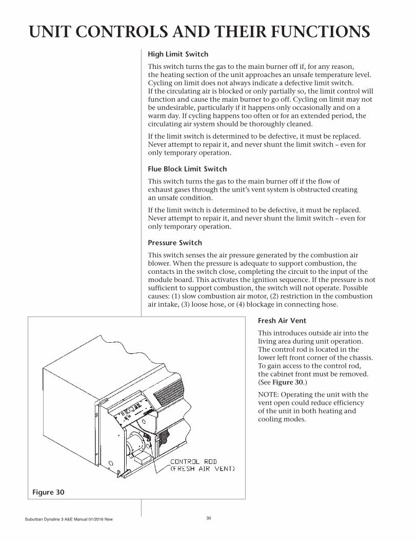
Fresh Air Vent
This introduces outside air into the living area during unit operation. The control rod is located in the lower left front corner of the chassis. To gain access to the control rod, the cabinet front must be removed. (See Figure 30.)
NOTE: Operating the unit with the vent open could reduce efficiency of the unit in both heating and cooling modes.
Figure 30

Suburban Dynaline 3 A&E Manual 01/2016 New31
SYSTEM
FAN
STANDBYHEATCOOLFAN ONLY
HIGHLOW
SET COOLERWARMER
SERVICE SYSTEM
Built-in Thermostat Control – Heat ModeInitial Lighting Instructions 1. Open the manual shut-off valve. The valve is fully open when the handle is level or parallel to the gas line. Never attempt to operate unit with manual valve partially closed.
2. Depress “System” key pad until heat lamp is illuminated. (See Figure 31.)
3. Depress “Fan” key pad until desired speed lamp is illuminated. (See Figure 31.)
4. Set thermostat to desired setting by depressing temperature-indicating arrows until desired temperature is displayed.
5. If the thermostat circuit is closed at the setting chosen in Step #4, the ignition sequence begins. After approximately 20-25 seconds, the main burner should be established.
6. After ignition, the operation of the unit will be controlled automatically by the thermostat.
To Shut Down for an Extended Period of Time
1. Depress “System” key pad until standby lamp is illuminated.
2. Close manual shutoff valve.
Sequence of Normal Operation – Heat Mode1. When heat is required, the thermostat closes and energizes the combustion air motor and the supply air motor.
2. As the blower reaches approximately 90% of the normal RPM, the pressure created by the combustion air motor causes the diaphragm in the pressure switch to move, closing the contacts. This completes the electrical circuit to the input of the module board and a 10-second warm-up period for the glo-bar is established. During the warm-up period, the glo-bar comes on for 10 seconds, then the valve opens. The glo-bar remains on another 3 seconds after the valve opens and then goes off. When the valve opens, it will remain open for 6 seconds. Gas will flow to the burner and be ignited by the glo-bar.
3. If the main burner flame is sensed, the burner will remain on until the thermostat is satisfied. If the flame is not sensed, the gas valve closes and the ignition sequence is automatically repeated two (2) times. If the burner does not light during this trial for ignition period, the unit will lock out for one (1) hour and then re-set automatically.
NOTE: If lock-out should occur, the unit can be re-set manually by selecting Standby and then selecting Heat Mode. The ignition procedures can now be repeated. Should repeated lock-out occur, shut unit down and contact service agency.
4. When the thermostat is satisfied, the valve closes. The combustion air motor will remain on for a 30-second purge cycle, then goes off. The room air blower will continue to operate for approximately 90 seconds at which time the circuit is opened and the room air blower goes off.
OPERATING INSTRUCTIONS DIGITAL KEY PAD CONTROL
Figure 31
SYSTEM
FAN
STANDBYHEATCOOLFAN ONLY
HIGHLOW
SET COOLERWARMER
SERVICE SYSTEM
Suburban Dynaline 3 A&E Manual 01/2016 New 32
Built-in Thermostat Control – Cooling Mode1. Depress “System” key pad until cool lamp is illuminated. (See Figure 31.)
2. Depress “Fan” key pad until desired speed lamp is illuminated. (See Figure 31.)
3. Set thermostat to desired setting by depressing temperature-indicating arrows until desired temperature is displayed.
4. If the thermostat circuit is closed at the setting chosen in Step #3, the cooling cycle begins.
NOTE: On initial start-up, the compressor will not be energized for five (5) minutes even though the system functions have been properly selected. This is to protect the compressor. This feature can be overridden by pressing the “System” and “Cooler” pads at the same time.
NOTE: Whenever the outside temperature is below 65°F and the humidity is high, frost could form on the evaporator coil during extended cooling operation. To eliminate frost formation, a de-ice switch in the compressor circuit will sense a frost condition and open the compressor circuit. Upon temperature rise, the switch will close and the compressor will again come on provided that the thermostat is still calling for cooling.
NOTE: Dynaline™ 3 has a built-in 5-minute delay between compressor cycles. Anytime the compressor cycle is interrupted either manually, through the thermostat, a power interruption, etc., the compressor will not restart for 5 minutes. Also, the A/C compressor has a minimum one-minute run time.
Remote Thermostat Control – Heat Mode Initial Lighting Instructions 1. Set wall thermostat to “Heat Mode.”
2. Open the manual shut-off valve. The valve is fully open when the handle is level or parallel to the gas line. Never attempt to operate unit with manual valve partially closed.
3. Set the wall thermostat at desired setting.
4. Select AUTO/FAN operation.
5. Using the “System” key pad, depress “Fan” key until desired speed lamp is illuminated.
NOTE: When Dynaline 3 is controlled by a wall thermostat, the sequence of operation is the same as with built-in thermostat control; however, the temperature setting and system functions are selected at the wall thermostat.
To Shut Down for an Extended Period of Time
1. Move selector on thermostat to “STOP” or “OFF” position.2. Close manual shut-off valve.

Suburban Dynaline 3 A&E Manual 01/2016 New33
Remote Thermostat Control – Cooling Mode1. Set wall thermostat to “Cool Mode.”
2. Set wall thermostat at desired setting.
3. Select AUTO/FAN operation.
4. Using the “System” key pad, depress “Fan” key until desired speed lamp is illuminated.
NOTE: When Dynaline™ 3 is controlled by a wall thermostat, the sequence of operation is the same as with built-in thermostat control; however, the temperature setting and system functions are selected at the wall thermostat.
NOTE: On initial start-up, the compressor will not be energized for five (5) minutes even though the system functions have been properly selected. This is to protect the compressor. This feature can be overridden by pressing the “System” and “Cooler” pads at the same time.
NOTE: Whenever the outside temperature is below 65°F and the humidity is high, frost could form on the evaporator coil during extended cooling operation. To eliminate frost formation, a de-ice switch in the com-pressor circuit will sense a frost condition and open the compressor circuit. Upon temperature rise, the switch will close and the compressor will again come on provided that the thermostat is still calling for cooling.
NOTE: Dynaline 3 has a built-in 5-minute delay between compressor cycles. Anytime the compressor cycle is interrupted either manually, through the thermostat, a power interruption, etc., the compressor will not restart for 5 minutes. Also, the A/C compressor, once started, will run for 1 minute even if the cooling mode is switched off.
Heat Mode or Cooling Mode1. At times it may be desirable to reduce the operating sound level. This is possible by selecting “Low” fan speed. (See Figure 31.)
2. Circulation of room air with no heat or cooling may be obtained if desired. To accomplish this, select the “Fan Only” position on the “System” key pad.
3. Operate unit with the fresh air vent in the closed position except when introduction of outside air into the room is desired.
4. Clean filter as part of regular maintenance.
5. Have regular professional maintenance to clean burners and ensure proper performance.
6. Keep windows and doors closed. Conditioned air escapes when they are open.
7. Operate at high fan speed during extremely hot or cold weather.
8. Keep outdoor condenser coil clean.
9. Turn the unit off during vacations or extended absences.
OPERATING TIPS

Suburban Dynaline 3 A&E Manual 01/2016 New 34
All optional and field installed
DESCRIPTIONWall Sleeve (knockdown)Rear Grille – Standard Aluminum AnodizedRear Grille – Dark Bronze Extruded AluminumRear Grille – Clear Anodized Extruded AluminumAir Discharge Lateral AdaptorAir Discharge Lateral Connector – 43"Air Discharge Lateral Extension – 43"Rear Gas Connection Kit – Field Installed2-PSIG RegulatorLeveling Legs, Set of 2 eachDecor Base Panel (conceals gas/electric connections)Condensate Drain Kit Wall Thermostat 24 VAC heat/cool88" Line Cord Accessory (Use with Dynaline 3 chassis when replacing
DL/DLII units in retrofit applications where the electrical receptacle is more than 20" right of wall opening.)
ACCESSORY DESCRIPTION REVIEW
Suburban Dynaline 3 A&E Manual 01/2016 New35
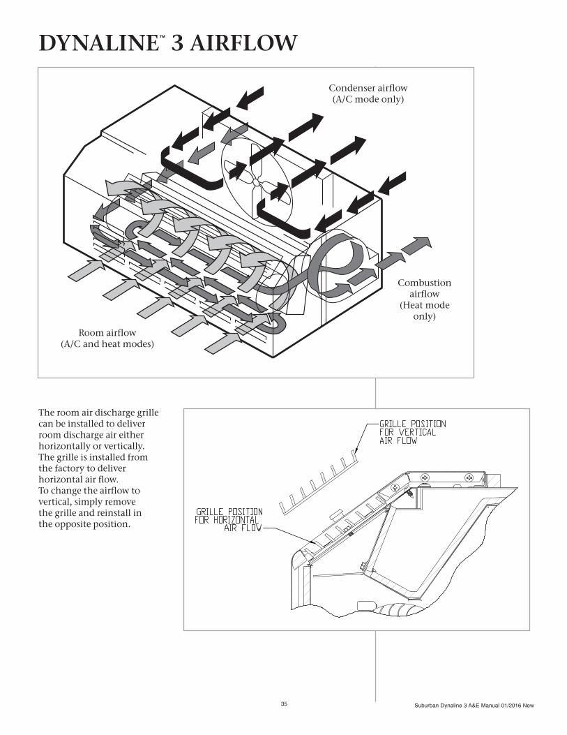
The room air discharge grille can be installed to deliver room discharge air either horizontally or vertically. The grille is installed from the factory to deliver horizontal air flow. To change the airflow to vertical, simply remove the grille and reinstall in the opposite position.
DYNALINE™ 3 AIRFLOW
Condenser airflow(A/C mode only)
Combustion airflow
(Heat mode only)
Room airflow(A/C and heat modes)

Suburban Dynaline 3 A&E Manual 01/2016 New 36
ONE-YEAR LIMITED WARRANTY
This SUBURBAN product is warranted to the original purchaser to be free from defects in material and workmanship under normal use and maintenance for a period of one year from the date of installation whether or not actual use begins on that date. It is the responsibility of the consumer/owner to establish the warranty period. Suburban does not use warranty registration cards for its standard warranty. You are required to furnish proof of installation date which may be a Bill of Sale or other payment records which verifies the original installation. A new or remanufactured part to replace any defective part will be provided to your dealer, service agency or local gas company, at Suburban’s sole option, without charge for the part itself, FOB the shipping point. THE EXCHANGED PART WILL BE WARRANTED FOR ONLY THE UNEXPIRED PORTION OF THE ORIGINAL WARRANTY. Defective parts must be returned to Suburban, transportation charges prepaid (Suburban is not responsible for any freight charges), where Suburban will establish to its sole satisfaction that the part was or became defective under normal use and maintenance. Said first year repairs, made by a recommended Suburban service agency, will qualify for labor reimbursement (to the service agency only) up to a maximum as established by Suburban’s flat rate schedule effective at that time. No reimbursement will be made for transportation, diagnosing, shipping or handling. THIS WARRANTY APPLIES ONLY TO THE PRODUCT IN ITS ORIGINAL INSTALLATION LOCATION AND IS VOIDED IF THE PRODUCT IS REINSTALLED ELSEWHERE.
FOUR YEAR LIMITED WARRANTY ON HEAT EXCHANGER AND COMPRESSORDuring the second through fifth years after the date of original installation, Suburban further warrants the heat exchanger against defects in material and workmanship under normal use and maintenance. A replacement heat exchanger will be provided under the same conditions as stated in the one year warranty EXCEPT no labor reim-bursement will be provided.
During the second through fifth years after the date of original installation, Suburban further warrants the compressor against defects in material or workmanship under normal use and maintenance. A new or re-manufactured compressor will be provided at Suburban’s sole option under the same conditions as stated in the one year warranty EXCEPT no labor reimbursement will be provided.
LIMITATION OF WARRANTIESALL IMPLIED WARRANTIES (INCLUDING IMPLIED WARRANTIES OF MERCHANTABILITY) ARE HEREBY LIMITED IN DURATION TO THE PERIOD FOR WHICH EACH LIMITED WARRANTY IS GIVEN. SOME STATES DO NOT ALLOW LIMITATIONS ON HOW LONG AN IMPLIED WARRANTY LASTS SO THE ABOVE LIMITATIONS MAY NOT APPLY TO YOU. THE EXPRESSED WARRANTIES MADE IN THIS WARRANTY ARE EXCLUSIVE AND MAY NOT BE ALTERED, ENLARGED, OR CHANGED BY ANY DISTRIBUTOR, DEALER OR OTHER PERSON WHOMSOEVER.
ALL WORK UNDER THE TERMS OF THIS WARRANTY SHALL BE PERFORMED DURING NORMAL WORKING HOURS. ALL REPLACEMENT PARTS ASSUME AS THEIR WARRANTY PERIOD ONLY THE REMAINING TIME PERIOD OF THIS WARRANTY.
SUBURBAN DYNALINE LIMITED WARRANTY

Suburban Dynaline 3 A&E Manual 01/2016 New37
SUBURBAN WILL NOT BE RESPONSIBLE FOR: 1. Normal maintenance as outlined in the owner’s installation, operating and service instructions manual
including cleaning of component parts; such as, orifices and burners.
2. Failure to start and/or operate due to voltage or gas conditions, blown fuses, open circuit breakers, loose or disconnected wires, low gas pressure or other damages due to inadequacy or interruption or electrical service or gas supply.
3. Damage or repairs required as a consequence of faulty or incorrect installation not in conformance with Suburban instructions.
4. Damage as a result of floods, winds, lightning, accidents, corrosive atmosphere or other conditions beyond the control of Suburban.
5. Costs incurred in gaining access to the furnace.
6. Parts or accessories not supplied by Suburban.
7. Damage or repairs needed as a consequence of any misapplication, abuse, unreasonable use, unauthorized alteration, improper service, improper operation or failure to provide reasonable and necessary maintenance.
8. Freight charges incurred from parts replacements.
9. Fuel or electricity costs or increases in such costs from any reason whatsoever.
10. Suburban products whose serial number has been altered, defaced or removed.
11. Suburban products installed or warranty claims originating outside the Continental U.S.A., Alaska, Hawaii and Canada.
12. ANY SPECIAL, INDIRECT OR CONSEQUENTIAL PROPERTY, ECONOMIC OR COMMERCIAL DAMAGE OF ANY NATURE WHATSOEVER. Some states do not allow the exclusion of incidental or consequential damages, so the above limitation may not apply to you.
NO REPRESENTATIVE, DEALER OR OTHER PERSON IS AUTHORIZED TO ASSUME FOR SUBURBAN MANUFACTURING COMPANY ANY ADDITIONAL, DIFFERENT OR OTHER LIABILITY IN CONNECTION WITH THE SALE OF THIS SUBURBAN PRODUCT.This warranty gives you specific legal rights, and you may also have other rights which vary from state to state.
IF YOU HAVE A PRODUCT PROBLEM
FIRST:Contact the installer of the equipment or the selling dealer for warranty service. You may find his name on the product or with your homeowners manual. If his name is not known, call your builder or general contractor if yours is a new structure.
SECOND:Contact the Suburban distributor who supplied the product to the installer/dealer.
THIRD:Contact: Suburban Manufacturing CompanyCustomer Service Department676 Broadway StreetDayton, Tennessee 37321(423) 775-2131, Ext. 7101Fax: (423) 775-7015www.suburbanmanufacturing.com

Suburban Dynaline 3 A&E Manual 01/2016 New 38
Weather Seals:
Sealing the chassis to the wall case, they prevent the infiltration of air, water
and contaminants into the conditioned area.
Condensate Removal: Condenser fan draws
condensate from bottom. Warm condenser air,
combined with coil temperature, accelerates the evaporation process.
Positive drain kits are also available.
Gas Heat Exchanger: Provides economical gas
heating backed by a 5-year limited warranty.
Copper and Aluminum Evaporator and Condenser Coils:
For longer life and ease of repair. Coils use seamless copper tubing mechanically
expanded into aluminum plate fins.
Attractive Stamped Aluminum or
Architectural-style Louvered Grilles:
Custom-colored architectural grilles are available to match
your building’s decor.
High-efficiencyRotary Compressor:
Reliable and quiet-running
design. Suburban’s gas heat PTAC design does not use the
compressor during heating cycles.
Digital Display:Room ambient and set point
temperatures are easy to read.
Features and Benefits
DYNALINE™ 3 PTAC

Suburban Dynaline 3 A&E Manual 01/2016 New39
Tangential Blower Wheel:
Spans the length of the
heating chamber and evaporatorcoil. Air flow is uniform over thesystem components, enhancing
air distribution performanceand system efficiency.
Electrical Components: Located on the indoor side
of the wall, they’re protected from the weather.
Ignition: The standard in gas heating, an electronically controlled,
hot surface ignites the burner without standing pilot lights.
Gas is conserved and safety is ensured.
Room Air Discharge: An attractive, durable grille
constructed of extruded aluminum directs air laterally.
Return Air Filter: No tools are needed to install
or remove the permanent electrostatic filter construct-
ed of washable media.
Unit Controls:Each unit can be controlled by a built-in thermostat or reprogrammed to operate
from an optional wall thermostat.
Air Vent:The manually-operated lever
allows entry of 70 CFM of outside air into the comfort area.
Gas Connection(Inside or Outside):
Available for Natural or LP gas, thus saving the cost
of field conversion. Optional 2-lb. Natural gas regulator
is available.

Please consult the Suburban Manufacturing website at www.SuburbanManufacturing.com for the latest product literature. Detailed dimensional data is available upon request. A complete warranty statement can be found in each product’s Installation/Operation Manual, on our website. As part of the Suburban continuous improvement program, specifications are subject to change without notice.
P.O. Box 400 • Cordele, GA 31010156 Seedling Drive • Cordele, GA 31015 Ph: 229-273-3636 • Fax: 229-273-5154Email: [email protected]
Manufactured by:
Suburban Dynaline 3 A&E Manual 01/2016 New40