Embed Size (px)
Citation preview
908 Canada CourtCity of Industry, CA 91748 U.S.A.
Phone: 626.964.7873 or 800.346.6668 Fax: 626.964.7880www.unicomlink.com e-mail: [email protected]
©UNICOM 2004. UNICOM and “A Network Systems Solution” are trademarks of UNICOM Electric, Inc.All rights reserved. Specifications subject to change without notice.Rev: 07.04
16 Port or 24 Port10/100Base-TX Fast Ethernet Switch
Dyna-Switch/16Dyna-Switch/24
USER’S MANUAL
FEP-31016T-2FEP-31024T-2

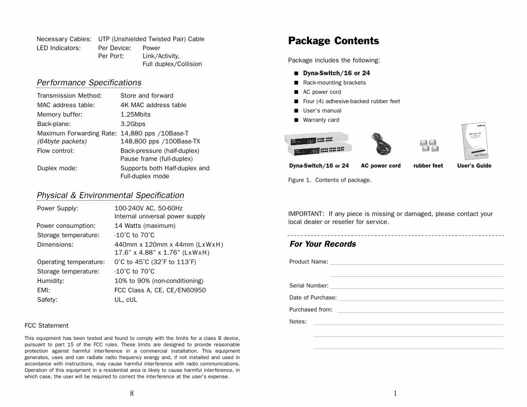
Package Contents
Package includes the following:
18
Necessary Cables: UTP (Unshielded Twisted Pair) CableLED Indicators: Per Device: Power
Per Port: Link/Activity,Full duplex/Collision
Performance SpecificationsTransmission Method: Store and forwardMAC address table: 4K MAC address tableMemory buffer: 1.25MbitsBack-plane: 3.2GbpsMaximum Forwarding Rate: 14,880 pps /10Base-T(64byte packets) 148,800 pps /100Base-TXFlow control: Back-pressure (half-duplex)
Pause frame (full-duplex)Duplex mode: Supports both Half-duplex and
Full-duplex mode
Physical & Environmental SpecificationPower Supply: 100-240V AC, 50-60Hz
Internal universal power supplyPower consumption: 14 Watts (maximum)Storage temperature: -10˚C to 70˚CDimensions: 440mm x 120mm x 44mm (LxWxH)
17.6” x 4.88” x 1.76” (LxWxH)Operating temperature: 0˚C to 45˚C (32˚F to 113˚F)Storage temperature: -10˚C to 70˚CHumidity: 10% to 90% (non-conditioning)EMI: FCC Class A, CE, CE/EN60950Safety: UL, cUL
FCC Statement
This equipment has been tested and found to comply with the limits for a class B device,pursuant to part 15 of the FCC rules. These limits are designed to provide reasonableprotection against harmful interference in a commercial installation. This equipmentgenerates, uses and can radiate radio frequency energy and, if not installed and used inaccordance with instructions, may cause harmful interference with radio communications.Operation of this equipment in a residential area is likely to cause harmful interference, inwhich case, the user will be required to correct the interference at the user’s expense.
� Dyna-Switch/16 or 24� Rack-mounting brackets
� AC power cord
� Four (4) adhesive-backed rubber feet
� User’s manual
� Warranty card
Dyna-Switch/16 or 24 AC power cord rubber feet User’s Guide
Figure 1. Contents of package.
IMPORTANT: If any piece is missing or damaged, please contact yourlocal dealer or reseller for service.
For Your Records
Product Name:
Serial Number:
Date of Purchase:
Purchased from:
Notes:
Introduction
The Dyna-Switch/16 and Dyna-Switch/24 (Auto MDI/MDIX) are FastEthernet switches that provide wire-speed, a Fast Ethernet switchingfunction which allows high-performance, low-cost connections to Full-duplex, Half-duplex, 10Mbps and 100Mbps Ethernet networks. TheSwitches are targeted at workgroup, department, or backbone computingenvironments in SME (small, medium enterprise) businesses.
These Switches provides auto-sensing 10/100Mbps Ethernet RJ-45 portswhich automatically detect the speed of the device that you plug into them.This switching function allows 10Mbps, 100Mbps, Full-duplex and Half-duplex devices to communicate on the same network without having toreplace any infrastructure. This flexible feature allows your network atimely, economical migration to 100Mbps Fast Ethernet.
Key Features� Automatic MDI/MDIX crossover for all ports
� N-Way Auto-negotiation for 10/100Mbps transmissions
� Auto-MDIX supported on all ports
� Store-and-Forward switching architecture
� Auto-detection of full/half-duplex mode in all ports
� 3.2Gbps switch backplane
� Embedded 1.25Mbits memory buffer
� 4K-entry MAC address table
� LED indicators for Power, Link/activity, and Full Duplex/Collision
� 19” Standard Rack Size
� Conforms to IEEE 802.3, 802.3u, and 802.3x standard
Troubleshooting
The Switch can be easily monitored through panel indicators to assist inidentifying problems. This section describes common problems you mayencounter and possible solutions.
� PowerIf the power indicator does not light when the power cord is pluggedin, you may have a problem with the power outlet or cord. However, ifthe power LED goes off after running for a while, check for loose powerconnections, power losses or surges at the power outlet. Turn offpower, wait 30 seconds and turn power on again. If problem is stillnot resolved, call for dealer’s assistance.
� CablingVerify that the cabling type is correct. Make sure all cable connectorsare securely seated in the required ports. Use only standardUnshielded Twisted-Pair (UTP), Category 3, 4, 5, or 5e cables. Useonly Category 5 or 5e when connecting with Fast Ethernet. Makecertain the maximum distance between the Switch and what it’sconnected to is 100 meters or less.
NOTE: Do not plug a standard telephone cord into an RJ-45 port. This may damage the switch or phone system.
Product SpecificationsGeneral SpecificationsStandard IEEE 802.3 10Base-T EthernetCompliance: IEEE 802.3u 100Base-TX Fast Ethernet
IEEE 802.3x Flow Control and Back-pressureIEEE ANSI/IEEE 802.3 N-way Auto-negotiation
Protocol CSMA/CDPorts: 10/100Mbps Auto-sensing RJ-45 ports with
Auto MDI/MDIX crossover Data Transfer Rate: Ethernet: 10Mbps (half-duplex)
20Mbps (full-duplex)Fast Ethernet: 100Mbps (half-duplex)
200Mbps (full-duplex)
72
For full coverage of your warranty, be sureto register your product using the enclosedregistration card.
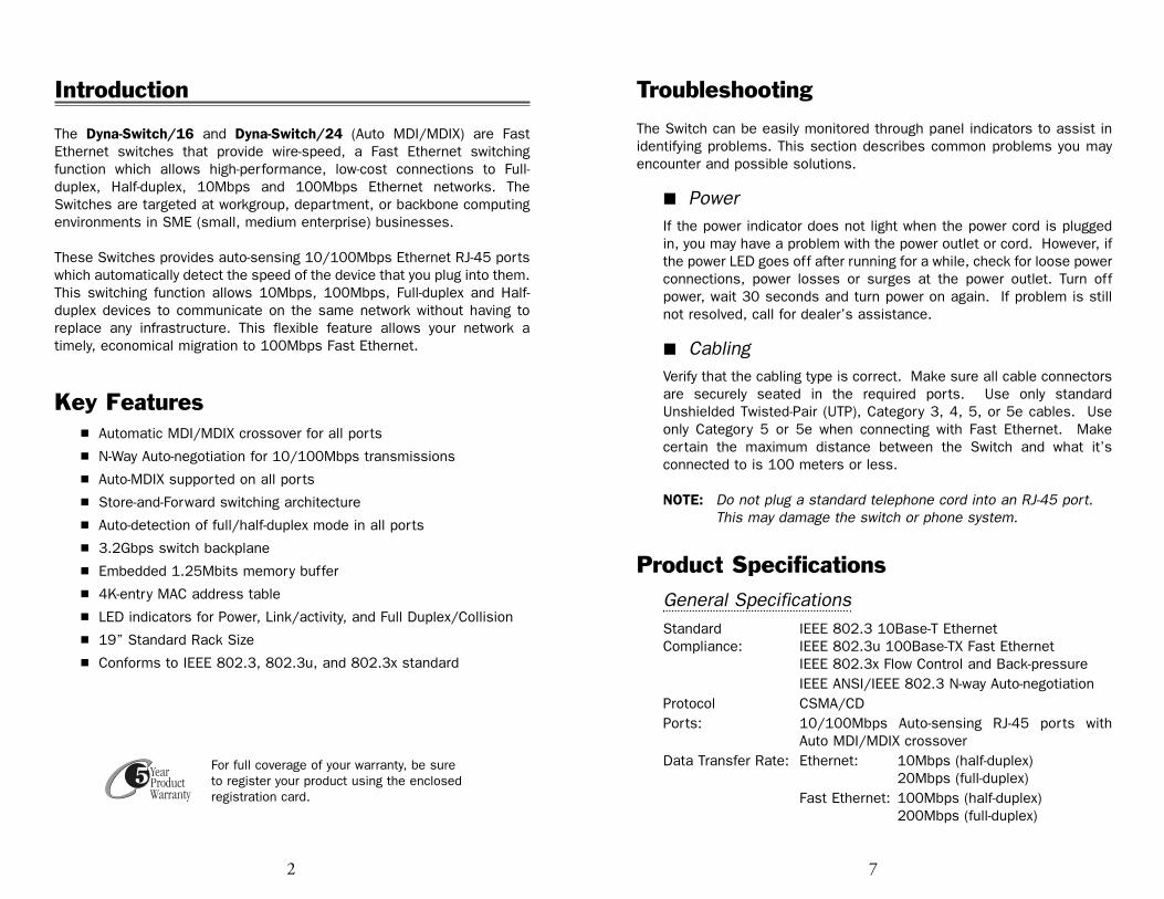
Hardware DescriptionThe Front Panel
The Front Panels of the Dyna-Switch/16 and 24 consist of10/100Base-TX RJ-45 ports and LED Indicators.
Figure 2. Front Panel views of Dyna-Switch/16 and 24
The Rear Panel
The 3-pronged power plug is located at the rear panel of theswitches as shown in the Figure 3. The Switch operates on AC in therange 100-240V AC, 50-60Hz.
Figure 3. Rear panel view of the Dyna-Switch/16 and 24
LED IndicatorsThe LED Indicators give real-time information of systematic operationstatus. The following table provides descriptions of the LED statusand their meanings.Per Device: PowerPer Port: LINK/ACT ( Link/Activity )
FDX/COL ( Full duplex/Collision )
For LED indication details, please refer to page 4.
36
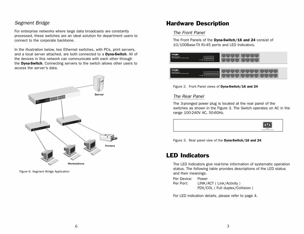
Segment Bridge
For enterprise networks where large data broadcasts are constantlyprocessed, these switches are an ideal solution for department users toconnect to the corporate backbone.
In the illustration below, two Ethernet switches, with PCs, print servers,and a local server attached, are both connected to a Dyna-Switch. All ofthe devices in this network can communicate with each other throughthe Dyna-Switch. Connecting servers to the switch allows other users toaccess the server’s data.
Printers
Server
Workstations
LK/ACT
FD/COL
FD/COL
LK/ACT
Dyna-Switch/16
16 Port 10/100Base-TX Switch POWER
Figure 6. Segment Bridge Application
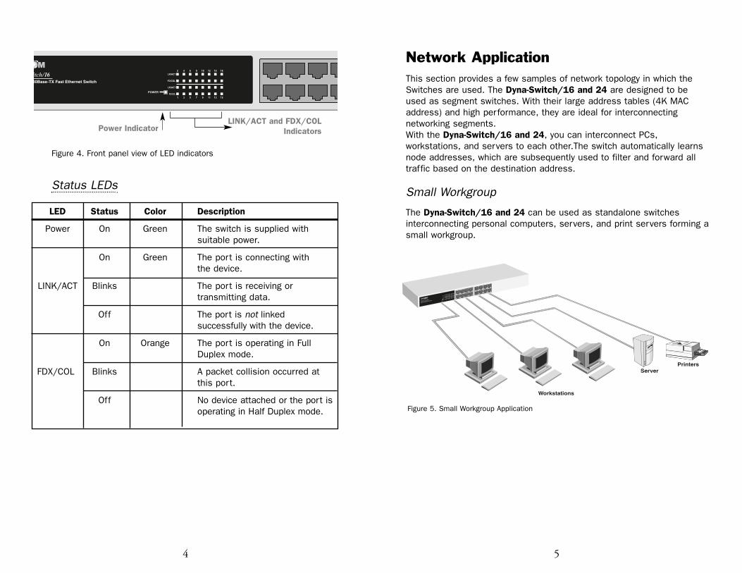
Figure 4. Front panel view of LED indicators
Status LEDs
Network ApplicationThis section provides a few samples of network topology in which theSwitches are used. The Dyna-Switch/16 and 24 are designed to beused as segment switches. With their large address tables (4K MACaddress) and high performance, they are ideal for interconnectingnetworking segments.With the Dyna-Switch/16 and 24, you can interconnect PCs,workstations, and servers to each other.The switch automatically learnsnode addresses, which are subsequently used to filter and forward alltraffic based on the destination address.
Small Workgroup
The Dyna-Switch/16 and 24 can be used as standalone switchesinterconnecting personal computers, servers, and print servers forming asmall workgroup.
54
LINK/ACT and FDX/COLIndicatorsPower Indicator
LED Status Color Description
Power On Green The switch is supplied withsuitable power.
On Green The port is connecting with the device.
LINK/ACT Blinks The port is receiving or transmitting data.
Off The port is not linked successfully with the device.
On Orange The port is operating in Full Duplex mode.
FDX/COL Blinks A packet collision occurred at this port.
Off No device attached or the port isoperating in Half Duplex mode.
PrintersServer
Workstations
LK/ACT
FD/COL
FD/COL
LK/ACT
Dyna-Switch/16
16 Port 10/100Base-TX Switch POWER
Figure 5. Small Workgroup Application