Embed Size (px)
Citation preview
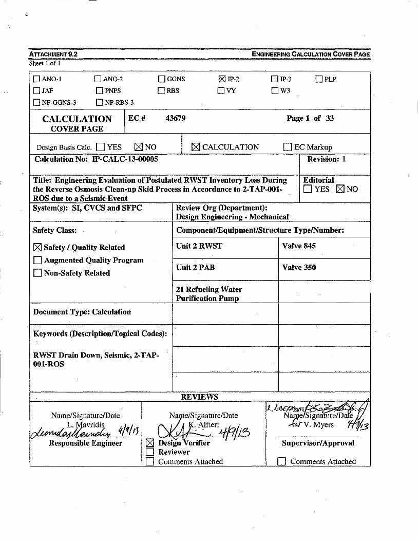
ATTACHMENT 9.2 ENGINEERING CALCULATION COVER PAGE.
Sheet 1of1
DAN0-1 DAN0-2 0GGNS IZI IP-2 DIP-3 0PLP
0JAF OPNPS ORBS 0VY 0W3
DNP-GGNS-3 DNP-RBS-3
CALCULATION EC# 43679 Page 1 of 33 COVER PAGE
Design Basis Cale. DYES [8JNO [8J CALCULATION 0ECMarkup
Calculation No: IP-CALC-13-00005 Revision: 1
Title: Engineering Evaluation of Postulated RWST Inventory Loss During Editorial the Reverse Osmosis Clean-up Skid Process in Accordance to 2-TAP-001- DYES [8J NO ROS due to a Seismic Event System(s): SI, CVCS and SFPC Review Org (Department):
Desi1!11 Emrlneerin2 - Mechanical
Safety Class: Component/Equipment/Structure Type/Number:
[8J Safety I Quality Related Unit2RWST Valve845 I •
D Augmented Quality Program
D Non-Safety Related Unit2PAB Valve 350
21 Refueling Water Purification Pump
Document Type: Calculation
Keywords (Description/Topical Codes): -
: RWST Drain Down, Seismic, 2-T AP-001-ROS
,
REVIEWS A
L.lie£MTM-1~-"" ~ Name/Signature/Date ~e/Signature/Date Nz/signa ure!Dat'e
~ 1t/1/1) 1JJJ.0lfieri 1-f/qfi~ V.Myers ~
Responsible Engineer [8J Design '1 erifier ' r Supervisor/ Approval D Reviewer D Comments Attached D Comments Attached
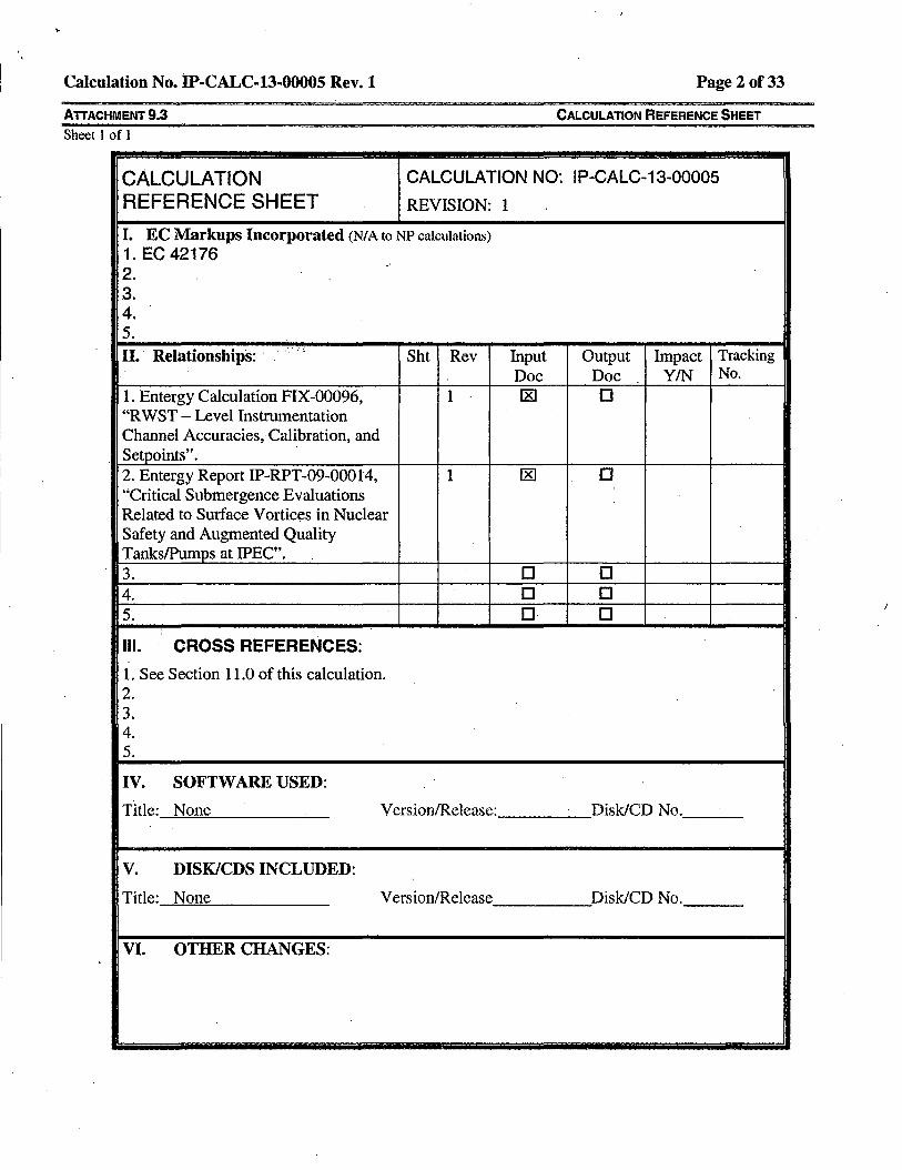
Calculation No. IP-CALC-13-00005 Rev.1 Page 2 of33
ATIACHMENT 9.3 CALCULATION REFERENCE SHEET
Sheet I of l
CALCULATION CALCULATION NO: IP-CALC-13-00005
REFERENCE SHEET REVISION: 1
I. EC Markups Incorporated (NIA to NP calculations) 1. EC 42176 , 2. 3. 4. 5. II. Relationships: ·
. .. _ ·:! Sht Rev Input Output Impact Tracking
Doc Doc YIN No.
1. Entergy Calculation FIX-00096, 1 [8] 0 "R WST - Level Instnunentation Channel Accuracies,·Calibration, and Setpoints". 2. Entergy Report IP-RPT-09-00014, 1 [8] 0 "Critical Submergence Evaluations Related to Surface Vortices in Nuclear Safety and Augmented Quality Tanks/Pumps at IPEC". 3. 0 0 4. 0 0 5. 0 0
;
Ill. CROSS REFERENCES:
1. See Section 11.0 of this calculation. 2. 3. 4. 5.
IV. SOFTWARE USED:
Title: None Version/Release: Disk/CD No.
v. DISK/CDS INCLUDED:
Title: None Version/Release Disk/CD No.
VI. OTHER CHANGES:
(
Calculation No. IP-CALC-13-00005 Rev.1 Page3 of33
AlTACHMENT 9.4 Sheet 1of1
0
1
RECORD OF REVISION
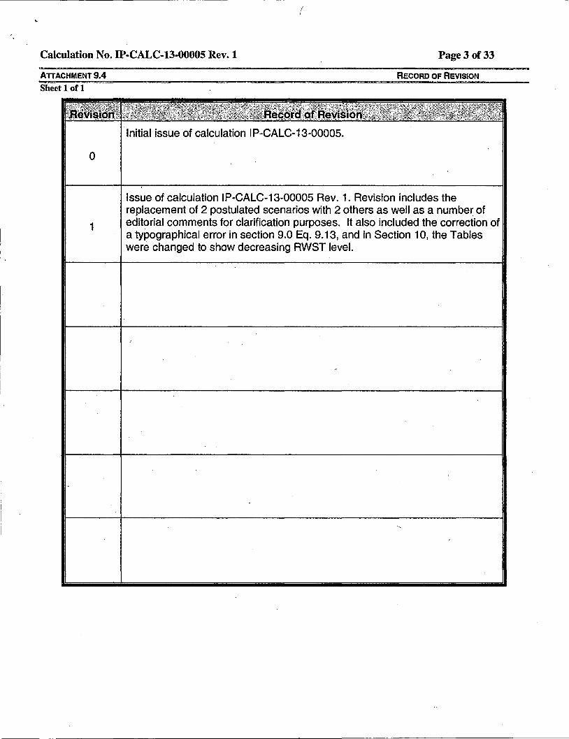
Initial issue of calculation I P-CALC-13-00005.
Issue of calculation IP-CALC-13-00005 Rev. 1. Revision includes the replacement of 2 postulated scenarios with 2 others as well as a number of editorial comments for clarification purposes. It also included the correction of a typographical error in section 9.0 Eq. 9.13, and in Section 10, the Tables were changed to show decreasing RWST level.
Calculation No. IP-CALC-13-00005 Rev. 1
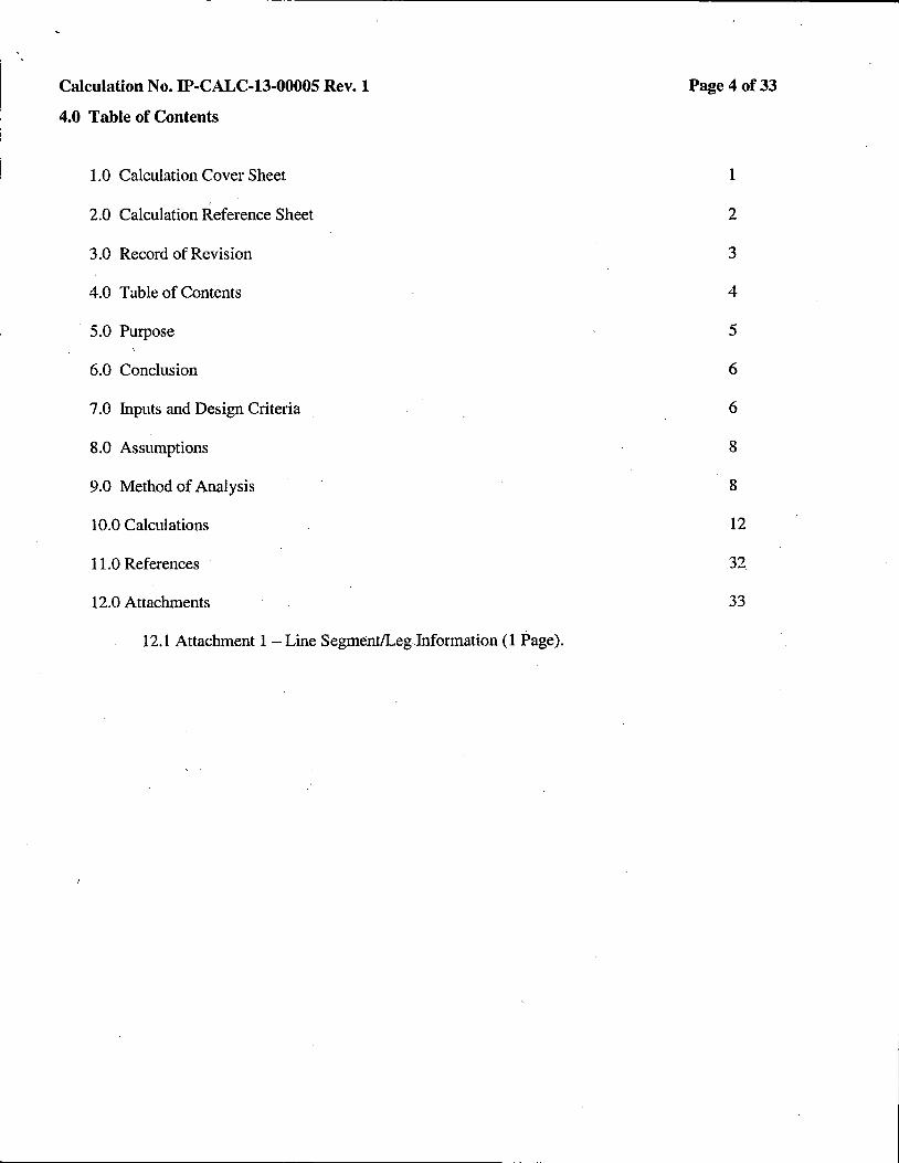
4.0 Table of Contents
1.0 Calculation Cover Sheet
2.0 Calculation Reference Sheet
3.0 Record of Revision
4.0 Table of Contents
5.0 Purpose
6.0 Conclusion
7 .0 Inputs and Design Criteria
8.0 Assumptions
9.0 Method of Analysis
10.0 Calculations
11.0 References
12.0 Attachments
12.1Attachment1 -Line Segment/LegJnformation (1 Page).
Page 4 of33
1
2
3
4
5
6
6
8
8
12
32_
33

Calculation No. IP-CALC-13-00005 Rev. 1
5.0 Purpose
Background
Page S of33
During steps outlined in procedure 2-T AP-001-ROS, "Installation/Removal of the Reverse Osmosis Silica Clean-up Skid", temporary hoses/connections are installed in order to nm the Unit 2 Osmosis Silica Clean-up Skid. The installation of the Reverse Osmosis Skid to Valve 725 (line #135) and to the flange downstream of valve 350 (line #2531252) creates an interface between seismic and non-seismic lines. These connections create new established pressure boundaries to the system as a whole during the operation of the Reverse Osmosis Skid.
Objective
The objective of this calculation is to determine maximum flow through a break at the seismic/non-seismic boundaries at valve 725 (line# 135) and at the flange downstream of valve 350 (line #253/252), and the time available prior to reaching the minimum Refueling Water Storage Tank Technical Specifications water level limit of 36.83' (Reference 5 and 22 per SR 3.5.4.2), based on the minimum and maximum water level that could be stored in the RWST (Overflow level is 37.65', Reference 5). Revision 1 includes cases E and F which require that the Low Level Alarm in the CCR be manipulated for the duration of operation for this purification skid. Also after conversations with Licensing and Operations, and based on Operations experience, it was decided that the objective of this calculation should be considered for each of the following 6 scenarios:
A. The Low Level Alarm in the CCR is set at 37.01. The rupture occurs during circumstances that do not call for an SI signal, in which case the purification pump is in operation.and the assumed operator time to respond and isolate Segment 1 is 3 minutes.
B. The Low Level Alarm in the CCR is set at 37.01. The rupture occurs during circumstances that do not call for an SI signal, fn which case the purification pump is in operation and the assumed operator time to respond and isolate Segment 1 is 5 minutes.
C. The Low Level Alarm in the CCR is set at 37.01. The rupture occurs during circumstances that call for an SI signal, in which case the purification pump will be stripped out of operation, all three SI pumps are assumed to be operating and the assumed operator time to respond and isolate Segli1ent 1 is 3 minutes.
D. The Low Level Alarm in the CCR is set at 37.01. The rupture occurs during circumstances that call for an SI signal, in which case the purification pump will be stripped out of operation, all three SI pumps are assumed to be operating and the assumed operator time to respond and isolate Segment 1 is 5 minutes.
E. The Low Level Alarm in the CCR is changed to 37.33 for the duration of the Purification Skid. The rupture occurs during circumstances that do not call for an SI signal, in which case the purification pump is in operation and the assumed operator time to respond and isolate Segment l is 10 minutes.
F. The Low Level Alarm in the CCR is changed to 37.33 for the duration of the Purification Skid. The rupture occurs during circumstances that call for an SI signal, in which case the purification pump will be stripped out of operation, all three SI pumps are assumed to be operating and the assumed operator time to respond and isolate Segment I is IO minutes.
Note: Isolating Segment 1 involves the closure of valves 845 and 727A as well as tripping the Purification Pump if necessary (During circumstances that do not call for an SI signal). Isolation of Segment 2 involves closing valve 350.

Calculation No. IP-CALC-13-00005 Rev. 1 Page 6 of33
6.0 Conclusion
The maximum time available prior to reaching the minimum RWST TS water level limits during a postulated break at the seismic/non-seismic boundaries at valve 725 (line# 135) and at the flange downstream of valve 350 (line #253/252) has been calculated for 6 different scenarios. Scenarios during circumstances that do not call for aii SI signal result in less time available for operator action. The maximum time available for scenarios A through Fas outlined in section 5.0 are tabulated below:
Postulated Scenario
A B c D E F
Table 6.1 Time to Reach TS Limits (Min) Based on Postulated Scenarios
Purification Safety Injection Assumed Time Pump Pumps to Isolate
QperatinQ QperatinQ Seament 1 Yes No 3.0 Yes No 5.0 No Yes 3.0 No Yes 5.0 Yes No 10.0 No Yes 10.0
Remaining Ti me to lsol ate
Seament 2 9.6 3.6
10.3 5.8
21.7 24.8
Note: For the calculated flow rate in each scenario refer to Tables 10.1through10.6. The values in Table 6.1 are based on a minimum water level in the RWST defined in each scenario description in section 5.
While the Table above demonstrates timing for specific RWST initial levels, the Tables in Section 10 demonstrate a wider rang~ of RWST initial levels and isolation times for Segment 1 and Segment 2.
7 .0 . Inputs and Design Criteria
Design Basis
1. Throughout this calculation, the paths from the RWST to each postulated break point are identified as follow:
a. Segment 1 begins at the 16" suction line from the RWST (line #155), through the 2" line leading to the Refueling Water Purification Pump (line #183), past the Refueling Water Purification Pump #21 through the 2" line and break point downstream of valve 725 (line #135) (Reference 1, 2, and 3).
b. Segment 2 begins at the 3" discharge line into the R WST (line # 16 l ), through the 2" line leading to the Boric Acid Blender in the CVCS (line #253), past valve 350 to the flange at the 2" line and break point downstream of valve 350 (line #252) (Reference l and 4).
2. The lengths of the Safety Injection and Auxiliary Coolant lines #155 (16"), #183 (2") and #135 (2") as well as the Safety Injection and Chemical Volume Control System lines #161 (3") and #253 and #252 (2") (Reference 1, 2, 3 and 4), are documented in the sununary tables in Attachment 1.
3. The number of fittings and components in the flow path of the Safety Injection and Auxiliary Coolant lines #155 (16"), #183 (2") and #135 (2") as well as the Safety Injection and Chemical and Volume Control System lines #161 (3") and #253 and #252 (2") (Reference 1, 2, 3 and 4), are documented in the summary tables in Attachment 1.
Calculation No. IP-CALC-13-00005 Rev.1 Page 7of33
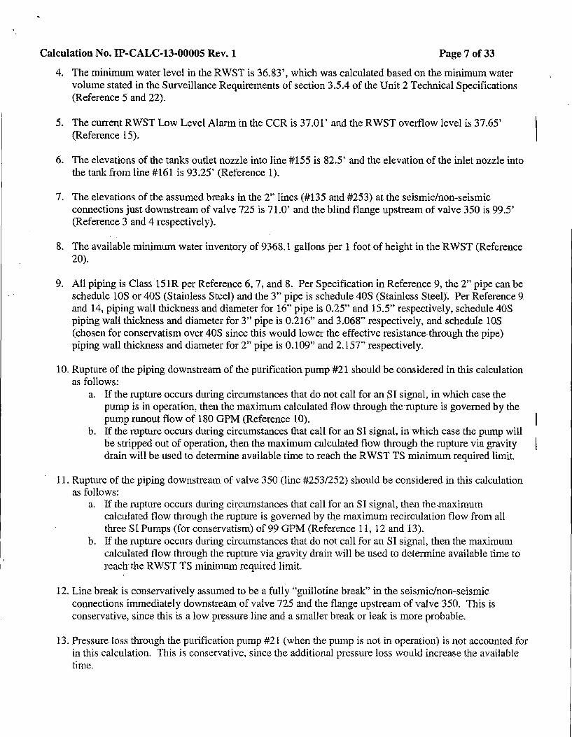
4. The minimum water level in the RWST is 36.83', which was calculated based on the minimum water volume stated in the Surveillance Requirements of section 3.5.4 of the Unit 2 Technical Specifications (Reference 5 and 22).
5. The current RWST Low Level Alarm in the CCR is 37.01' and the RWST overflow level is 37.65' (Reference 15).
6. The elevations of the tanks outlet nozzle into line #155 is 82.5' and the elevation of the inlet nozzle into the tank from line #161 is 93.25' (Reference 1).
7. The elevations of the assumed breaks in the 2" lines (#135 and #253) at the seismidnon-seismic connections just downstream of valve 725 is 71.0' and the blind flange upstream of valve 350 is 99.5' (Reference 3 and 4 respectively).
8. The available minimum water inventory of 9368.1 gallons per 1 foot of height in the RWST (Reference 20).
9. All piping is Class 151R per Reference 6, 7, and 8. Per Specification in Reference 9, the 2" pipe can be schedule lOS or 40S (Stainless Steel) and the 3" pipe is schedule 40S (Stainless Steel). Per Reference 9 and 14, piping wall thickness and diameter for 16" pipe is 0.25" and 15.5" respectively, schedule 40S piping wall thickness and diameter for 3" pipe is 0.216" and 3.0~8" respectively, and schedule lOS (chosen for conservatism over 40S since this would lower the effective resistance through the pipe) piping wall thickness and diameter for 2" pipe is 0.109" and 2.157" respectively.
10. Rupture of the piping downstream of the purification pump #21 should be considered in this calculation as follows:
a. If the rupture occurs during circumstances that do not call for an SI signal, in which case the pump is in operation, then the maximum calculated flow through the mpture is governed by the pump runout flow of 180 GPM (Reference 10).
b. If the rupture occurs during circumstances that call for an SI signal, in which case the pump will be stripped out of operation, then the maximum calculated flow through the mpture via gravity drain will be used to determine available time to reach the RWST TS minimum required limit.
11. Rupture of the piping downstream of valve 350 (line #253/252) should be considered in this calculation as follows:
a. If the rupture occurs during circumstances that call for an SI signal, then the-maximum calculated flow through the rupture is governed by the maximum recirculation flow from all three SI Pumps (for conservatism) of 99 GPM (Reference 11, 12and13).
b. If the rupture occurs during circumstances that do not call for an SI signal, then the maximum calculated flow through the mpture via gravity drain will be used to determine available time to reach the RWST TS minimum required limit.
12. Line break is conservatively assumed to be a fully '"guillotine break" in the seismic/non-seismic connections immediately downstream of valve 725 and the flange upstream of valve 350. This is conservative, since this is a low pressure line and a smaller break or leak is more probable.
13. Pressure loss through the purification pump #21 (when the pump is not in operation) is not accounted for in this calculation. This is conservative, since the additional pressure loss would increase the available time.
Calculation No. IP-CALC-13-00005 Rev. 1 Page 8of33
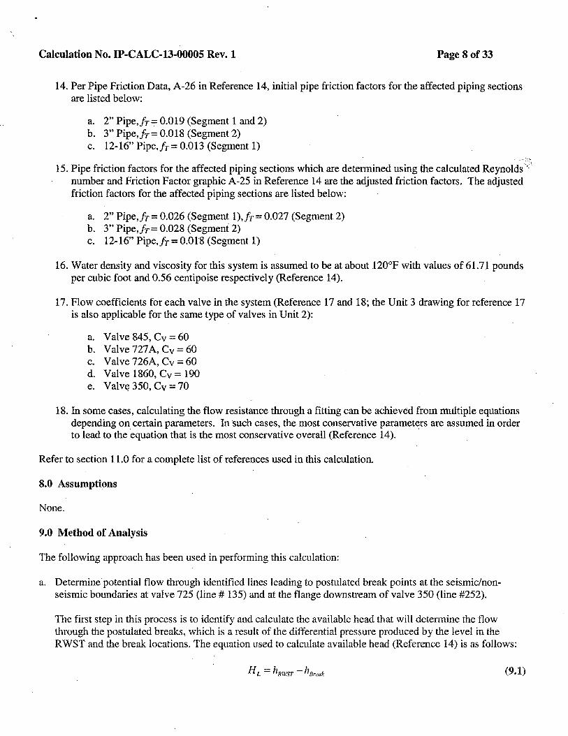
14. Per Pipe Friction Data, A-26 in Reference 14, initial pipe friction factors for the affected piping sections are listed below:
a, 2" Pipe,JT= 0.019 (Segment 1and2) b. 3" Pipe.fr= 0.018 (Segment 2) c. 12-16" Pipe,Jr = 0.013 (Segment 1)
. -- :-_ .. 15. Pipe friction factors for the affected piping sections which are determined using the calculated Reynolds .. ·:'
number and Friction Factor graphic A-25 in Reference 14 are the adjusted friction factors. The adjusted friction factors for the affected piping sections are listed below:
a. 2" Pipe, fT = 0.026 (Segment 1 ), fr= 0.027 (Segment 2) b. 3" Pipe.fr= 0.028 (Segment2) c. 12-16" Pipe,Jr=0.018(Segment1)
16. Water density and viscosity for this system is assumed to be at about 120°F with values of 61.71 pounds per cubic foot and 0.56 centipoise respectively (Reference 14).
17. Flow coefficients for each valve in the system (Reference 17 and 18; the Unit 3 drawing for reference 17 is also applicable for the same type of valves in Unit 2):
a. Valve 845, Cv = 60 b. Valve 727A, Cv = 60 c. Valve 726A, Cv = 60 d. Valve 1860, Cv = 190 e. Valv~ 350, Cv = 70
18. In some cases, calculating the flow resistance through a fitting can be achieved from multiple equations depending on certain parameters. In such cases, the most conservative parameters are assumed in order to lead to the equation that is the most conservative overall (Reference 14). ,
Refer to section 11.0 for a complete list of references used in this calculation.
8.0 Assumptions
None.
9.0 Method of Analysis
The following approach has been used in performing this calculation:
a. Determine· potential flow through identified lines leading to postulated break points at the seismic/nonseismic boundaries at valve 725 (line# 135) and at the flange downstream of valve 350 (line #252).
The first step in this process is to identify and calculate the available head that will detennine the flow through the postulated breaks, which is a result of the differential pressure produced by the level in the RWST and the break locations. The equation used to calculate available head (Reference 14) is as follows:
H L = hRWST -hBreuk (9.1)
Calculation No. IP-CALC-13-00005 Rev.1
Where: H L = Available Head (ft)
hRwsr = Elevation of level in the RWST (ft)
h8,.ak = Elevation of break in the system (ft)
Page9of33
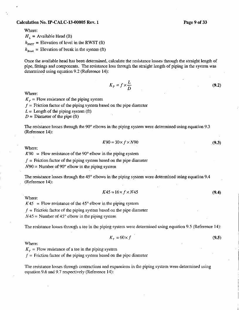
Once the available head has been determined, calculate the resistance losses through the straight length of pipe, fittings and components. The resistance loss through the straight length of piping in the system was determined using equation 9.2 (Reference 14):
Where:
L Kr =fx
D
KP = Flow resistance of the piping system
f = Friction factor of the piping system based on the pipe diameter L = Length of the piping system (ft) D = Diameter of the pipe (ft)
The resistance losses through the 90° elbows in the piping system were determined using equation 9.3 (Reference 14):
K90 = 30 x f x N90 Where: K90 = Flow resistance of the 90° elbow in the piping system
f = Friction factor of the piping system based on the pipe diameter
N90 = Number of 90° elbow in the piping system
The resistance losses through the 45° elbows in the piping system were detennined using equation 9.4 (Reference 14):
K45=16xfxN45 Where: K 45 = Flow resistance of the 45°• elbow in the piping system
f = Friction factor of the piping system based on the pipe diameter
N45 =Number of 45° elbow in the piping system
(9.2)
.(9.3)
(9.4)
The resistance losses through a tee in the piping system were determined using equation 9.5 (Reference 14):
Kr =60xf Where: Kr = Flow resistance of a tee in the piping system
f = Friction factor of the piping system based on the pipe diameter
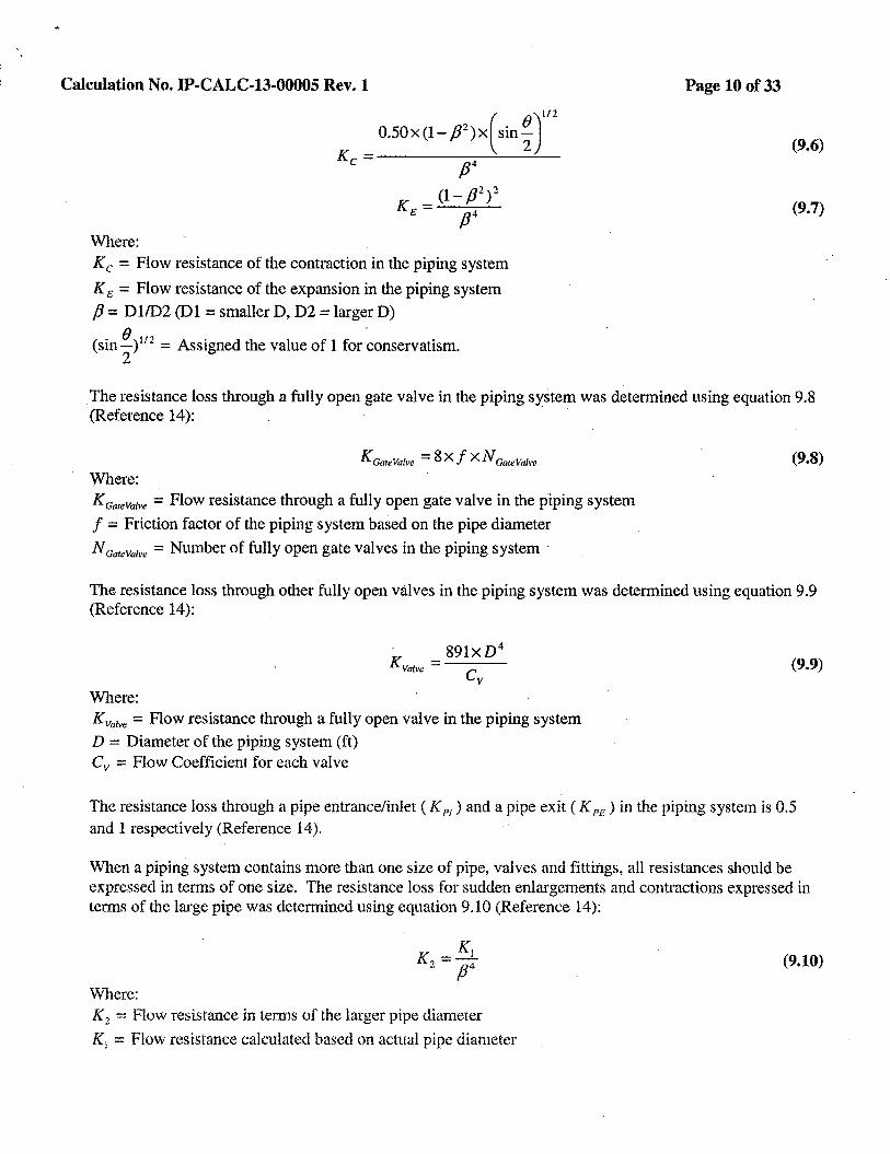
The resistance losses through contractions and expansions in the piping system were determined using equation 9.6 and 9.7 respectively (Reference 14):
(9.5)
Calculation No. IP-CALC-13-00005 Rev. 1
Where: Kc = Flow resistance of the contraction in the piping system
KE = Flow resistance of the expansion in the piping system
p = Dl/D2 (Dl =smaller D, D2 =larger D)
(sine )112 = Assigned the value of l for ~onservatism. 2
Page 10of33
(9.6)
(9.7)
The resistance loss through a fully open gate valve in the piping system was determined using equation 9.8 (Reference 14): ·
K Ga1eVafre = 8 X J X N GateVafre
Where: KcareValve = Flow resistance through a fully open gate valve in the piping system
f = Friction factor of the piping system based on the pipe diameter
N caieVafre = Number of fully open gate valves in the piping system ·
(9.8)
The resistance loss through other fully open valves in the piping system was determined using equation 9.9 (Reference 14):
Where: Kvafre = Flow resistance through a fully open valve in the piping system D = Diameter of the piping system (ft) Cv =Flow Coefficient for each valve
(9.9)
The resistance loss through a pipe entrance/inlet ( K PI) and a pipe exit ( K PE) in the piping system is 0.5 and l respectively (Reference 14).
\\<'hen a piping system contains more than one size of pipe, valves and fittings, all resistances should be expressed in terms of one size. The resistance loss for sudden enlargements and contractions expressed in terms of the large pipe was detennined using equation 9.10 (Reference 14):
Where:
K =Ki 2 p4
K2 = Flow resistance in tem1s of the larger pipe diameter
K1 = Flow resistance calculated based on actual pipe diameter
(9.10)
, Calculation No. IP-CALC-13-00005 Rev. 1 Page 11 of33
fJ = Dl/D2 (Dl =smaller D, D2 =larger D)
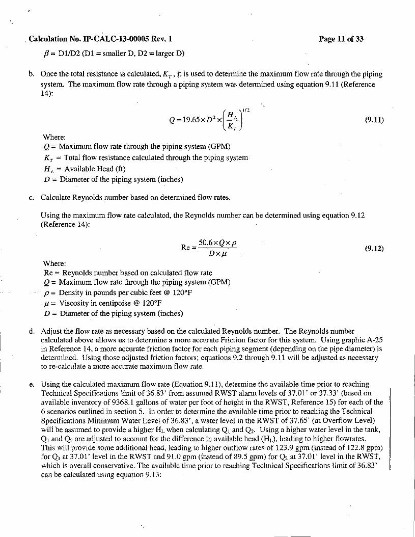
b. Once the total resistance is calculated, KT, it is used to determine the maximum flow rate through the piping
system. The maximum flow rate through a piping system was detem1ined using equation 9 .11 (Reference 14):
Where:
( )
l/2
Q=l9.65xD2 x HL KT
Q = Maximum flow rate through the piping system (GPM)
KT = Total flow resistance calculated through the piping system
H L = Available Head (ft)
D = Diameter of the piping system (inches)
c. Calculate Reynolds number based on determined flow rates.
Using the maximum flow rate calculated, the Reynolds number can be determined using equation 9.12 (Reference 14):
Where:
Re= 50.6xQxp Dxµ
Re = Reynolds number based on calculated flow rate Q = Maximum flow rate through the piping system (GPM)
p = Density in pounds per cubic feet @ 120°F
. µ = Viscosity in centipoise @ 120°F D = Diameter of the piping system (inches)
(9.11)
(9.12).
d. Adjust the flow rate as necessary based on the calculated Reynolds number. The Reynolds number calculated above allows us to determine a more accurate Friction factor for this system. Using graphic A-25 in Reference 14, a more accurate friction factor for each piping segment (depending on the pipe diameter) is determined. Using those adjusted friction factors; equations 9.2 through 9.11 will be adjusted as necessary to re-calculate a more accurate maximum flow rate.
e. Using the calculated maximum flow rate (Equation 9.1 l), determine the available time prior to reaching Technical Specifications limit of 36.83' from assumed RWST alarm levels of 37.01' or 37.33' (based on available inventory of 9368.1 gallons of water per foot of height in the RWST; Reference 15) for each of the 6 scenarios outlined in section 5. In order to determine the available time prior to reaching the Technical Specifications Minimum Water Level of 36.83', a water level in the RWST of 37.65' (at Overflow Level) will be assumed to provide a higher HL when calculating Q1 and Q2• Using a higher water level in the tank, Q1 and Q2 are adjusted to account for the difference in available head (HL), leading to higher flowrates. This will provide some additional head, leading to higher outflow rates of 123.9 gpm (instead of 122.8 gpm) for Q1 at37.01' level in the RWST and 91.0 gpm (instead of 89.5 gpm) for Q2 at 37.01' level in the RWST, which is overall conservative. The available time prior to reaching Technical Specifications limit of 36.83' can be calculated using equation 9.13:
Calculation No. IP-CALC-13-00005 Rev. 1 Page 12of33
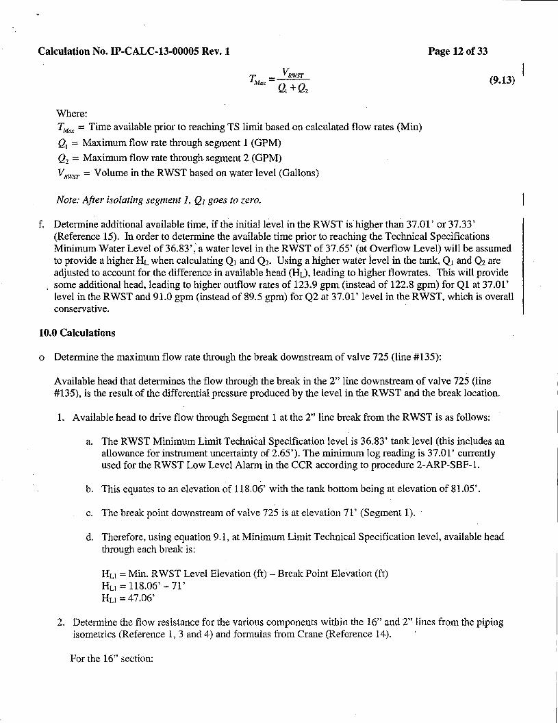
(9.13)
Where: TMux = Time available prior to reaching TS limit based on calculated flow rates (Min)
Q1 = Maximum flow rate through segment 1 (GPM)
Q2 = Maximum flow rate through segment 2 (GPM)
VRwsT = Volume in the RWST based on water level (Gallons)
Note: After isolating segment 1, Q1 goes to zero.
f. Determine additional available time, if the initial level in the RWST is higher than 37.01' or 37.33' (Reference 15). In order to determine the available time prior to reaching the Technical Specifications Minimum Water Level of 36.83' ,'a water level in the RWST of 37.65' (at Overflow Level) will be assumed to provide a higher HL when calculating Q1 and Q2• Using a higher water level in the tank, Q1 and Q2 are adjusted to account for the difference in available head (HL), leading to.higher flowrates. This will provide some additional head, leading to higher outflow rates of 123.9 gpm (instead of 122.8 gpm) for Ql at 37.01' level in the RWST and 91.0 gpm (instead of 89.5 gpm) for Q2 at 37.01' level in the RWST, which is overall conservative.
10.0 Calculations
o Determine the maximum flow rate through the break downstream of valve 725 (line #135):
Available head that determines the flow through the break in the 2" line downstream of valve 725 (line #135), is the result of the differential pressure produced by the level in the RWST and the break location.
1. Available head to drive flow through Segment 1 at the 2" line break from the RWST is as follows:
a. The RWST Minimum Limit TechniCal Specification level is 36.83' tank level (this includes an allowance for instrument uncertainty of 2.65'). The minimum log reading is 37.01' currently used for the RWST Low Level Alarm in the CCR according to procedure 2-ARP-SBF-l.
b. This equates to an elevation of 118.06' with the tank bottom being at elevation of 81.05'.
c. The break point downstream of valve 725 is at elevation 71' (Segment l).
d. Therefore, using equation 9.1, at Minimum Limit Technical Specification level, available head through each break is:
Hu= Min. RWST Level Elevation (ft) - Break Point Elevation (ft) Hu = 118.06' - 71' Hu= 47.06'
2. Determine the flow resistance for the various components within the 16" and 2" lines from the piping isometrics (Reference 1, 3 and 4) and formulas from Crane (Reference 14).
For the 16" section:
Calculation No. IP-CALC-13-00005 Rev.-1
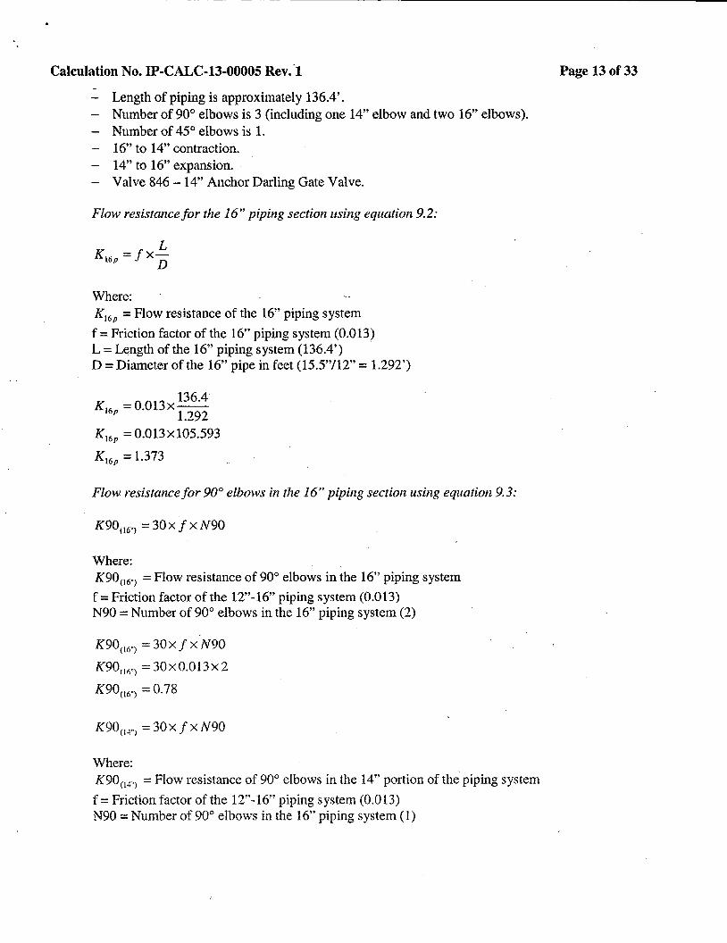
- Length of piping is approximately 136.4'. - Number of 90° elbows is 3 (including one 14" elbow and two 16" elbows). - Number of 45° elbows is 1. - 16" to 14" contraction. - 14" to 16" expansion. - Valve 846-14" Anchor Darling Gate Valve.
Flow resistance for the 16" piping section using equation 9.2:
L Kt6p =fx
D
Where: K16 P =Flow resistance of the 16" piping system
f =Friction factor of the 16" piping system (0.013) L =Length of the 16" piping system (136.4') D =Diameter of the 16" pipe in feet (15.5"/12" = 1.292')
K = 0.013x 136
.4 16p 1.292
K 16 P = 0.013x105.593
K 16P = 1.373
Flow resistance for 90° elbows in the 16" piping section using equation 9.3:
K90 06 .. ) = 30 x f x N90
Where: K9006 .. > =Flow resistance of 90° elbows in the 16" piping system
f =Friction factor of the 12"-16" piping system (0.013) N90 =Number of 90° elbows in the 16" piping system (2)
K9006 .. ) = 30x f x N90
K90n 6"l = 30x0.013x 2
K90<16 .. ) = 0.78
K90 <14 .. 1 = 30 x f x N90
Where: K90<14 .. l =Flow resistance of 90° elbows in the 14" portion of the piping system
f =Friction factor of the 12"-16" piping system (0.013) N90 = Number of 90° elbows in the 16" piping system ( 1)
Page 13of33
..
Calculation No. IP-CALC-13-00005 Rev.1
K90 04 .> = 30 x f x N90
K90(14.> = 30x0.013xl
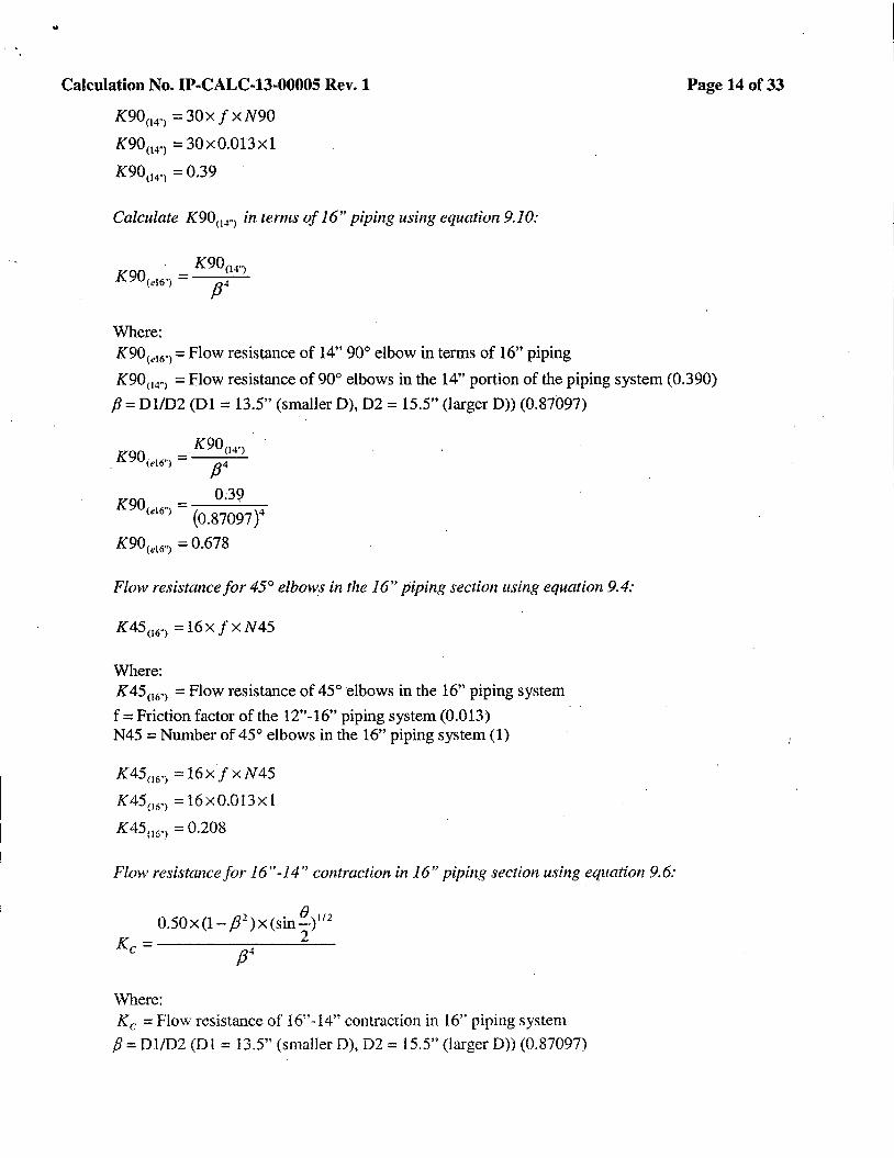
K90< 14-i = 0.39
Calculate K9004.> in terms of 16" piping using equation 9.10:
K90<14 .. > K90<cl6") = /34
Where: K90<e16·i =Flow resistance of 14" 90° elbow in terms of 16" piping
Page 14of33
K90< 14.> =Flow resistance of 90° elbows in the 14" portion of the piping system (0.390)
p = 01/02 (Dl = 13.5" (smaller 0), 02 = 15.5" (larger D)) (0.87097)
K9004 .. >
. K90<e16"> = /34
K90 - 0;39 (el6") - (0.87097)4
K90<•16 .. > = 0.678
Flow resistance for 45° elbows in the 16" piping section using equation 9.4:
K45 06.> =16xfxN45
Where: K45 06 .. > =Flow resistance of 45° elbows in the 16" piping system
f =Friction factor of the 12"-16" piping system (0.013) N45 =Number of 45° elbows in the 16" piping system (1)
K4506 .. > =16xfxN45
K45< 16.> = 16x0.013xl
K45 06 .. , = 0.208
Flow resistance for 16 "-14" contraction in 16" piping section using equation 9. 6:
{} .
0.50x(l-/32 )x(sin-) 112
K - 2 C• - /34
Where: Kc =Flow resistance of 16"-14" contraction in 16" piping system
p = Dl/D2(D1 = 13.5" (smaller D), 02 = 15.5" (larger 0)) (0.87097)
Calculation No. IP-CALC-13-00005 Rev. 1
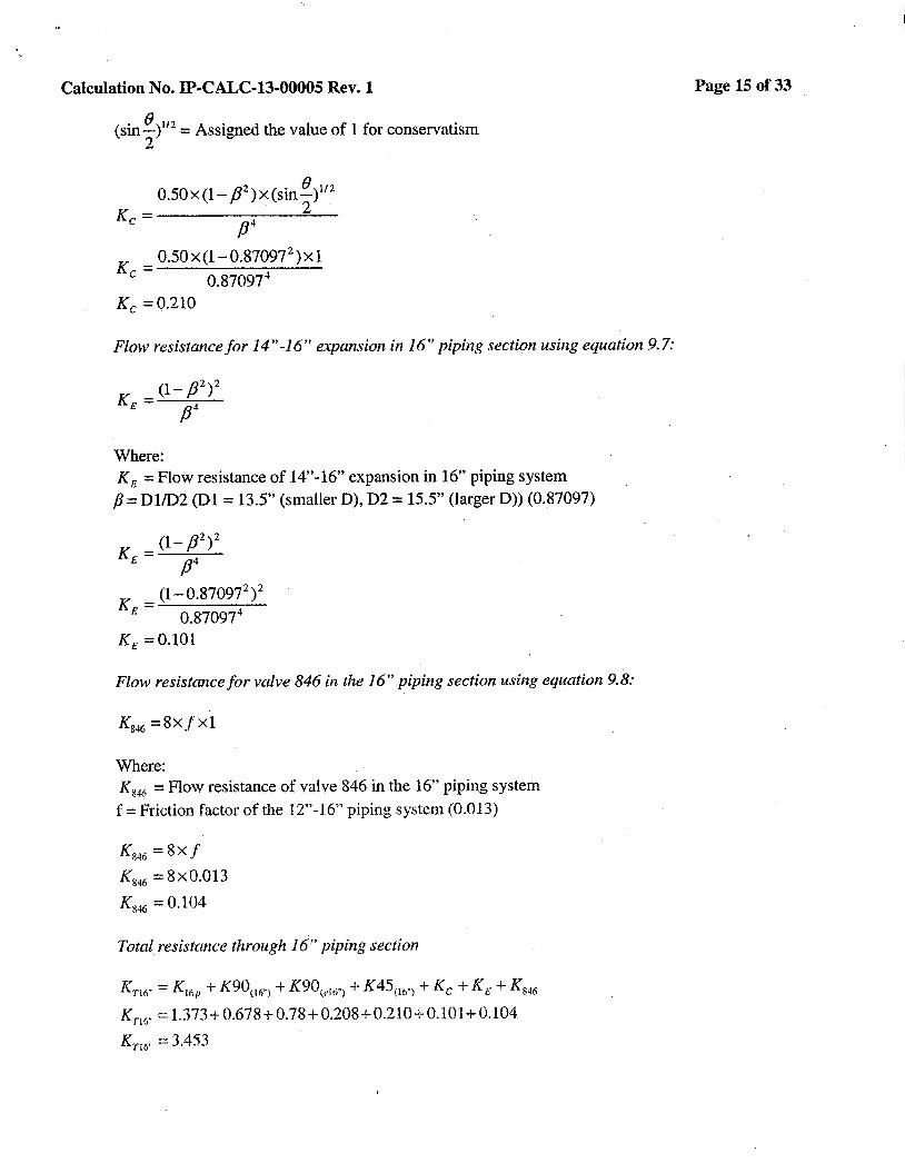
(sin() )112 =Assigned the value of 1 for conservatism 2
0.50x(l- p2 )x(sin 8
)112
K - 2 c - p4
K _ 0.50x(l-0.87097 2 )xl c - 0.870974
Kc =0.210
Flow resistance for 14"-16'' expansion in 16" piping section using equation 9.7:
Where: KE =Flow resistance of 14"-16" expansion in 16" piping system
fJ = Dl/D2 (Dl = 13.5" (smaller D), D2 = 15.5" (larger D)) (0.87097)
(1- p2)2 KE= p4
K = (1-0.870972
)2
E 0.870974
KE =0.101
Flow resistance for valve 846 in the 16" piping section using equation 9.8:
K846 =8Xf Xl
Where: K 846 =Flow resistance of valve 846 in the 16" piping system
f =Friction factor of the 12"-16" piping system (0.013)
Ks46 =8Xf
K846 = Sx0.013
K846 = 0.104
Total resistance through 16" piping section
Krt6 .. = K16P + K90(16.l + K90\el6"l + K45(Iti") +Kc+ KE+ K846
Km .. == 1.373+ 0.678+0.78+0.208+0.210+0.101+0.104
Km .. = 3.453
Page 15 of33
Calculation No. IP-CALC-13-00005 Rev. 1
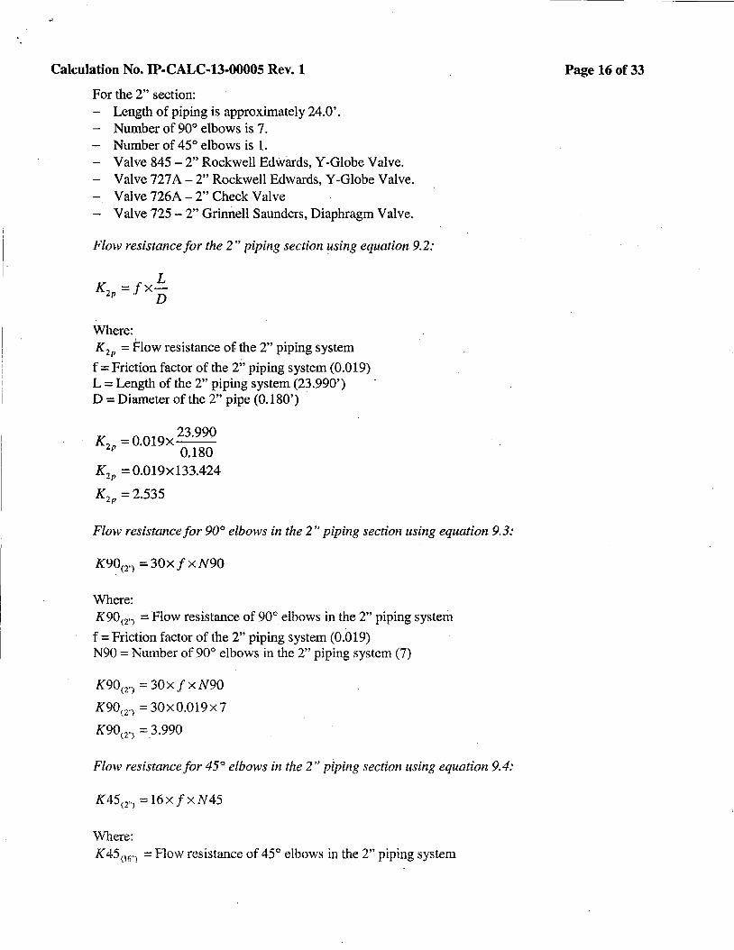
For the 2" section: - Length of piping is approximately 24.0'. - Number of 90° elbows is 7.
Number of 45° elbows is 1. - Valve 845-2" Rockwell Edwards, Y-Globe Valve. - Valve 727 A - 2" Rockwell Edwards, Y-Globe Valve. - Valve 726A- 2" Check Valve - Valve 725 - 2" Grinnell Saunders, Diaphragm Valve.
Flow resistance for the 2" piping section using equation 9.2:
Where: K2 P =Flow resistance of the 2" piping system
f =Friction factor of the 2" piping system (0.019) L =Length of the 2" piping system (23.990') D =Diameter of the 2" pipe (0.180')
K =0.019x23
·990
2P 0.180
K2P = 0.019xl33.424
K1 p =2.535
Flow resistance for 90° elbows in the 2" piping section using equation 9. 3:
K90<2"l =30xfxN90
Where: K90<2") =Flow resistance of 90° elbows in the 2" piping system
f =Friction factor of the 2" piping system (0.019) N90 =Number of 90° elbows in the 2" piping system (7)
K90< 2"J = 30x .f x N90
K90<2") = 30x0.019x7
K90<2"J =_3.990
Flow resistance for 45° elbows in the 2" piping section using equation 9.4:
K 45 <1") = 16 x f x N 45
Where: K 45 06 .. } =Flow resistance of 45° elbows in the 2" piping system
Page 16of33

Calculation No. IP-CALC-13-00005 Rev. 1
f =Friction factor of the 2" piping system (0.019) N45 =Number of 45° elbows in the 2" piping system (1)
K45<Z") = 16xf xN45
K45cz·> = 16x0.019xl
K45<n = 0.304
Flow resistance for valve 845 in the 2" piping section using equation 9. 9:
K _ 891xD4
845 - cz v
Where: . K845 =Flow resistance of valve 845 in the 2" piping system
Cv Coefficient = 60 (Reference 18) D =Diameter (2.157")
. 891xD4
Ks4s = ci v
K. _ 891x2.157 4
845 - 602
K 845 = 5.358
Flow resistance for valve 72 7 A in the 2 ·: piping section using equation 9. 9:
K _ 891xD4
727A - C2 v
Where: K727.1 =Flow resistance of valve 727 A in the 2" piping system
Cv Coefficient= 60 (Reference 18) D =Diameter (2.157")
89lxD4
K121A = c2 v
K = 891x2.1574
727A 602
K 727 A = 5.358
Flow resistance for valve 726A in the 2" piping section using equation 9.9:
Page 17of33
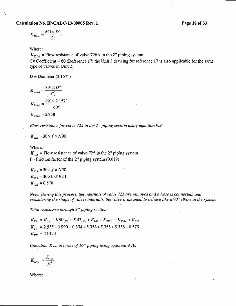
I Calculation No. IP-CALC-13-00005 Rev. 1 Page 18of33
K _ 89lxD 4
726A - C2 v
Where: K727A =Flow resistance of valve 726A in the 2" piping system
Cv Coefficient= 60 (Reference 17; the Unit 3 drawing for reference 17 is also applicable for the same type of valves in Unit 2)
D =Diameter (2.157")
K _ 891XD 4
n6,\ - c2 v
K = 891x2.1574
726.4. 602
K726A = 5.358
Flow resistance for valve 725 in the 2" piping section usi1tg equation 9.3:
K725 =30xf xN90
Where: K125 =Flow resistance of valve 725 in the 2" piping system
f =Friction factor of the 2" piping system (0.019)
K725 = 30xf xN90
K125 = 30x0.019Xl
K 725 =0.570
Note: During this process, the internals of valve 725 are removed and a hose is connected, and considering the shape of valves internals, the valve is assumed to behave like a 90° elbow in the system.
Total resistance through 2" piping section:
Kn" = K 2 ,, + K90(2"> + K45(2"l + K 845 + K 721 A + K726 A + K 725
Kn- = 2.535 + 3.990 + 0.304 + 5.358 + 5.358 + 5.358 + 0.570
KT2" = 23.473
Calculate Kr2" in terms of 16" piping using equation 9.10:
. KT? .. Kre16" = --t-
/J
Where:

Calculation No. IP-CALC-13-00005 Rev.1
K7
e16
• =Flow resistance of 2" total in terms of 16" piping system
f3 = Dl/D2 (Dl = 2.157" (smaller D), 02 = 15.5" (larger D)) (0.139161)
Kn· Krew=y
K _ 23.473 Tel
6" - (0.139161)4
KTel6" = 62586.538
Total resistance through entire piping section:
KT = KTe\6" + KT16" + Kinter + Kexit
KT2" = 62586.538 + 3.453+0.5+1
K.1'2" = 62591.492
Page 19of33
3. Calculate maximum flow through the combined 16" and 2" piping.section using equation 9.11:
(H )112
Q1 =19.65xDL6"x ;
Where: Q1 =Flow in GPM
D16 .. =Diameter in terms of 16" pipe (15.5")
H L =Available Head due to elevation only (47.06')
K = Total resistance ( 62591.492)
(H )112
Q1 =19.65XD(6 .. X ;
)
If"
Q = 19.65x15.5 2 x( 47·06 ~
l 62591.492
Q1 =129.45
o Based on the above flow rate, calculate the Reynolds Number using equation 9.12:
Re= 50.6xQxp Dxµ
Where: Q =Flow in GPM D = Diameter ( l 5 .5" and 2.1. 57") p =Density in pound per cubic feet@ 120°F (61.71)
J,i =Absolute viscosity in centepoise @ 120°F (0.56)

Calculation No. IP-CALC-13-00005 Rev. 1 Page 20of33
For the 16" section:
R _ 50.6xQ1 xp
e16· -D16.xµ
R _ 50.6x129.45x61.71 eiii· - 15.5x0.56
Rel6" = 4.66E +04
At the above Reynolds No., friction factor is approximately equal to 0.018 for the 16" piping section as per figure A-25 of Reference 14. This number is greater thtln the assumed value of 0.013. Therefore, flow resistance of the piping system needs to be adjusted and re-computed using a friction factor of 0.018 for the 16" piping section instead of 0.013.
For the 2" section:
', Re2
.. = 50.6xQ1 xp Drxµ
R 50.6x129.45x61.71 e2" = 2.1S7x0.56
Re 2 .. = 3.350£ + 05 --
At the above Reynolds No., friction factor is approximately equal to 0.026 for the 2" piping section as \ .
per figure A-25 of Reference 14. This number is greater than the assumed value of 0.019. Therefore, flow resistance of the piping system needs to be adjusted and re-computed using a friction factor of 0.026 for the 2" piping section instead of 0.019.
o Adjust the calculated flow rate by going through the calculation steps using equations 9.2 through 9.11 adjusting the flow resistance through the system, where applicable, with the new friction factors based on the above determined Reynolds number:
For the 16" Pipe: K 16r = 1.901
K9006 .. > = 1.08
K90c016 .. ) = 0.938
K45<16 .. i = 0.288
Kc= 0.210
KE= 0.101
K 846 = 0.144
Kn6 .. = 4.662
For the 2" Pipe:
K2P = 3.469
K90< 2 .. 1 = 5.46
K45t2 "> = 0.416
- (
Calculation No. IP-CALC-13-00005 Rev. 1
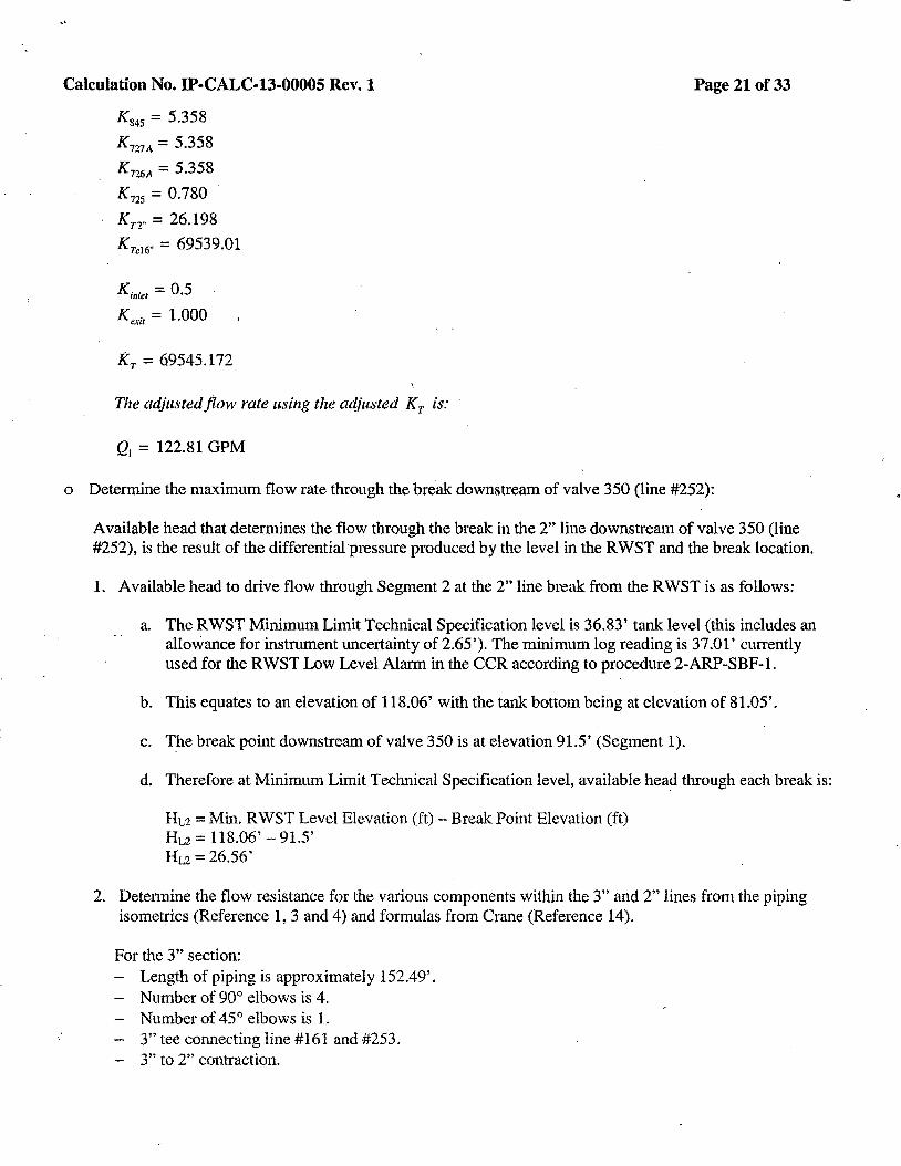
K845 = 5.358
K727A = 5.358
K726A = 5.358
K 125 = 0.780
Kn .. = 26.198
KTel 6" = 69539.01
Kin/et= 0.5
Kexit = 1.000
KT= 69545.172
The adjusted flow rate using the adjusted Kr is:
Q1 = 122.81 GPM
Page 21of33
o Determine the maximum flow rate through the break downstream of valve 350 (line #252):
Available head that determines the flow through the break in the 2" line downstream of valve 350 (line #252), is the result of the differential pressure produced by the level in the RWST and the break location.
1. Available head to drive flow through Segment 2 at the 2" line break from the RWST is as follows:
a. The RWST Minimum Limit Technical Specification level is 36.83' tank level (this includes an allowance for instrument uncertainty of 2.65'). The minimum log reading is 37.01' currently used for the RWST Low Level Alarm in the CCR according to procedure 2-ARP-SBF-1.
b. This equates to an elevation of 118.06' with the tank bottom being at elevation of 81.05'.
c. T_he break point downstream of valve 350 is at elevation 91.5' (Segment 1).
d. Therefore at Minimum Limit Technical Specification level, available head through each break is:
HL2 ==Min. RWST Level Elevation (ft) - Break Point Elevation (ft) Hu== 118.06' - 91.5' Hu== 26.56'
2. Determine the flow resistance for the various components within the 3" and 2" lines from the piping isometrics (Reference 1, 3 and4) and formulas from Crane (Reference 14).
For the 3" section: - Length of piping is approximately 152.49'. - Number of 90° elbows is 4. - Number of 45° elbows is L
3" tee connecting line # 161 and #253. - 3" to 2" contraction.
,.
Calculation No. IP-CALC-13-00005 Rev.1
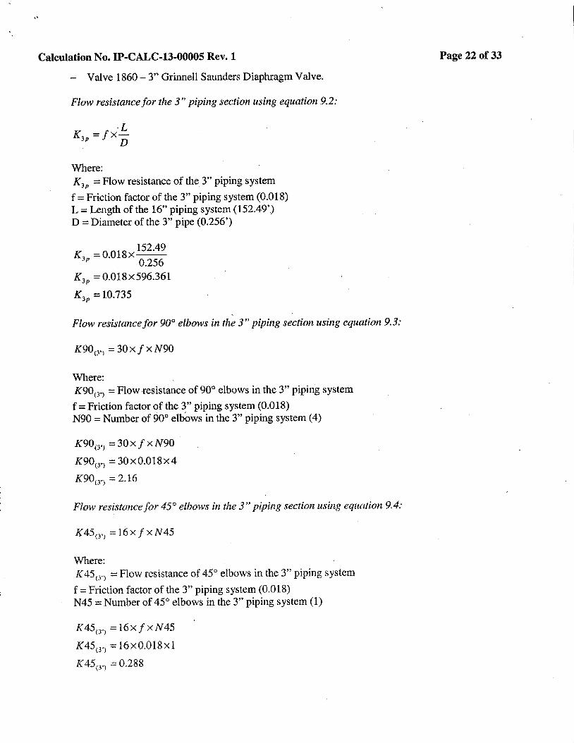
- Valve 1860- 3" Grinnell Saunders Diaphragm Valve.
Flow resistance for the 3" piping section using equation 9.2:
L K3p =fx
D
Where: K 3P =Flow resistance of the 3" piping system
f =Friction factor of the 3" piping system (0.018) L =Length of the 16" piping system (152.49') D =Diameter of the 3" pipe (0.256')
K = 0.018x 152
.49
Jp 0.256
K3P = 0.018x596.361
K 3P = 10.735
Flow resistance for 90° elbows in the 3" piping section using equation 9.3:
K90<3.l = 30xf xN90
Where: K90< 3") =Flow resistance of 90° elbows in the 3" piping system
f =Friction factor of the 3" piping system (0.018) N90 =Number of 90° elbows in the 3" piping system (4)
K90<J"> = 30xf xN90
K90(3.> = 30x0.018x4
K9013 .. l = 2.16
Flow resistance for 45° elbows in the 3" piping section using equation 9.4:
K45 0 .l = 16xf x N45
Where: K45cn =Flow resistance of 45° elbows in the 3" piping system
f =Friction factor of the 3" piping system (0.018) N45 =Number of 45° elbows in the 3" piping system (1)
K45crJ =16xfxN45
K45w) = 16x0.018xl
K 45<3") = 0.288
Page 22of33
Calculation No. IP-CALC-13-00005 Rev.1
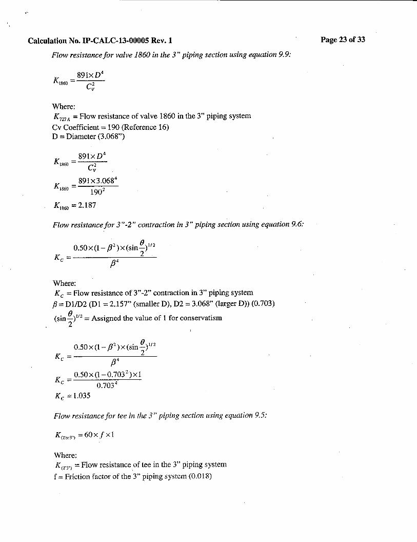
Flow resistance for valve 1860 in the 3" piping section using equation 9. 9:
K _ 891XD4
1s60 - c2 v
Where: K727A =Flow resistance of valve 1860 in the 3" piping system
Cv Coefficient = 190 (Reference 16) D = Dian1eter (3.068")
K _ 891xD 4
1s60 - c2 v
K _ 891x3.0684
1860 - 1902
Ki860 = 2.187
Flow resistance for 3 "-2" contraction in 3" piping section using equation 9. 6:
0.50x(l-/J2)x(sin 8
)112
K 2 . c - /34
Where: Kc= Flow resistance of 3"-2" contraction in 3" piping system
fJ = Dl/D2 (Dl = 2.157" (smaller D), D2 = 3.068" (larger D)) (0.703)
(sin 8 )112 = Assigned the value of 1 for conservatism 2
0.50 x (1- /32) x (sin
8 )111
K - 2 c - /34
K .. = 0.50x(l-0.7032)xl
c 0.703 4
Kc = 1.035
Flow resistance for tee in the 3" piping section using equation 9.5:
Km:eJ") = 60XfX1
Where: K(n"> =Flow resistance
1of tee in the 3" piping system
f =Friction factor of the 3" piping system (0.018)
Page 23of33
Calculation No. IP-CALC-13-00005 Rev. 1
K(Tee3") = 60x f K(Tee 3") = 60X0.018
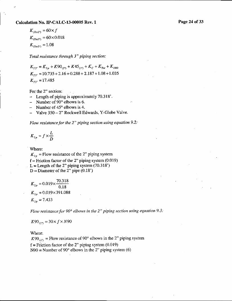
K(Tee3") = 1.08
Total resistance through 3" piping section:
Kn .. = K 3P + K90(3.> + K45(J"l +Kc+ K1e• + K1860
Kn· = 10.735 + 2.16 + 0.288+2.187+1.08+1.035
Kn .. = 17.485
For the 2" section: - Length of piping is approximately 70 .318'. - Number of 90° elbows is 6. - Number of 45° elbows is 4. - Valve 350-2" Rockwell Edwards, Y-Globe Valve.
Flow resistance for the 2" piping section using equation 9.2:
L K2p=fX-. D
Where: K 2P =Flow resistance of the 2" piping system
f =Friction factor of the 2" piping system (0.019) L =Length of the 2" piping system (70.318') D =Diameter of the 2" pipe (0.18')
K =0.019x 70318
2P 0.18
K2 P = 0.019x391.088
K 2P = 7.433
Flow resistance for 90° elbows in the 2" piping section using equation 9.3:
K90(n =30xfxN90
Where: K90l 2"l =Flow resistance of 90° elbows in the 2" piping system
f =Friction factor of the 2" piping system (0.019) N90 =Number of 90° elbows in the 2" piping system (6)
· Page 24 of 33
I
Calculation No. IP-CALC-13-00005 Rev. 1
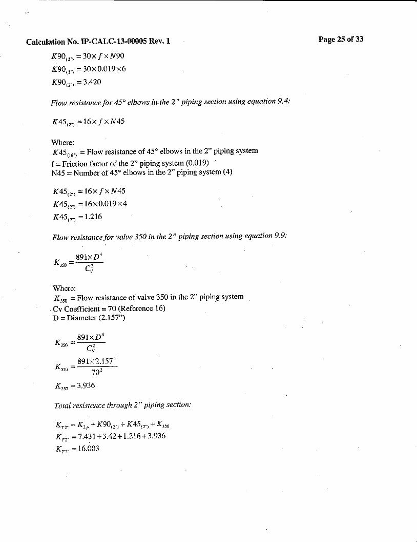
K90< 2") = 30x f x N90
K90cr) = 30x0.019x6
K90cr> = 3.420
Flow resistance for 45° elbows in-the 2" piping section using equation 9.4:
K45< 2"l = 16x f x N45
Where: K45
06.> =Flow resistance of 45° elbows in the 2" piping system
f =Friction factor of the 2" piping system (0.019) .. , N45 =Number of 45° elbows in the 2" piping system (4)
K45m =16xfxN45
K45<2"> = 16x0.019x4
K45<2 .. l = 1.216
Flow resistance for valve 350 in the 2" piping section using equation 9.9:
K _ 89lxD4
3so - c2 v
Where: K
350 =Flow resistance of valve 350 in the 2" piping system
. Cv Coefficient = 70 (Reference 16) D =Diameter (2.157")
K = 891XD4
350 c2 v
K = 89lx2.l574
350 702
K 350 =3.936
Total resistance through 2" piping section:
Kn .. = K 2P + K90< 2-> + K45cz"> + K 350
Kn·= 7.431+3.42+1.216+ 3.936
Kn .. = 16.003
Page 25 of33
i
Calculation No. IP-CALC-13-00005 Rev. 1 Page 26of33
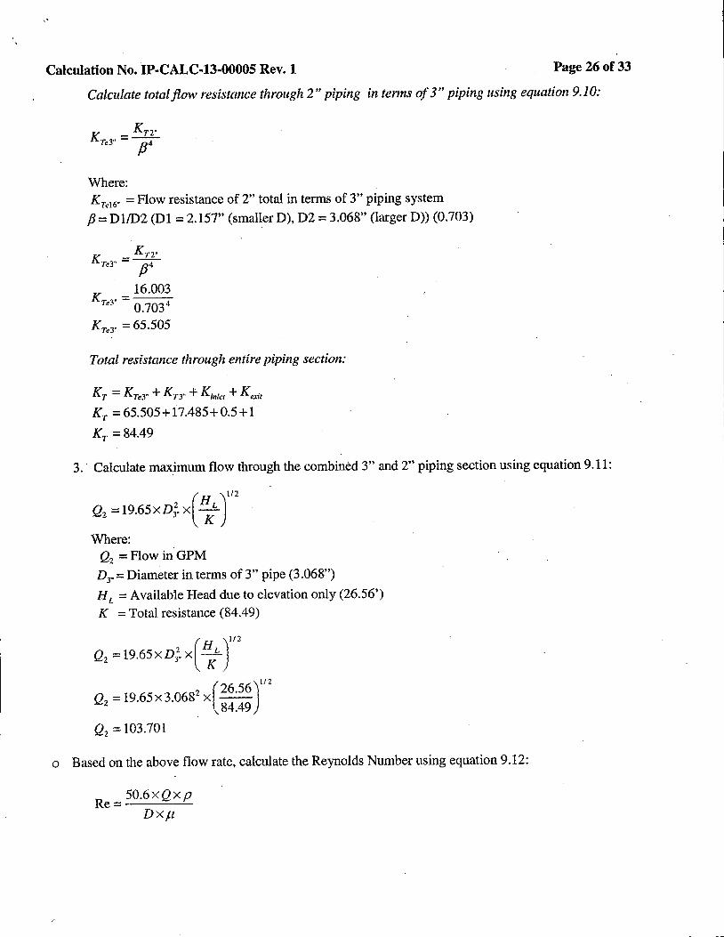
Calculate total flow resistance through 2" piping in terms of 3" piping using equation 9.10:
Where: Kre16• =Flow resistance of 2" total in terms of 3" piping system
P = Dl/D2 (Dl = 2.157" (smaller D), D2 = 3.068" (larger D)) (0.703)
Kr2· KTe3" =y K _ 16.003
Te3" - 0.7034
KTeJ" = 65 .505
Total resistance through entire piping section:
KT= KTe3" + KT3" + Ki11/e1 + Kexit
KT = 65.505+17.485+0.5+1
KT =84.49
3. Calculate maximum flow through the combined 3" and 2" piping section using equation 9 .11:
(H )112
Q2 =19.65xv;. x KL
Where: Q2 = Flow in GPM
D3
.. = Diameter in terms of 3" pipe (3.068")
HL =Available Head due to elevation only (26.56') K = Total resistance (84.49)
(H )112
Q2 =19.65xv;. x ;
Q2 =19.65x3.0682 x(26·56
)112
84.49
Q2=103.701
o Based on the above flow rate, calculate the Reynolds Number using equation 9.12:
Re= 50.6xQxp Dxµ

Calculation No. IP-CALC-13-00005 Rev.1 Page 27of33
Where: Q =Flow in GPM D= Diameter (3.068" and 2.157") p =Density in pound per cubic feet@ 120°F (61.71)
µ =Absolute viscosity in centepoise@ 120°F (0.56)
For the 3" section:
R _ 50.6xQ1 xp
e3" - D3.xµ R 50.6x103.701x61.71
e 3• = 3.068 x 0.56
Re 3 .. =l.88E+05
At the above Reynolds No., friction factor is approximately equal to 0.028 for the 3" piping section as per figure A-25 of Reference (14). This number is greater than the assumed value of 0.018. Therefore, flow resistance of the piping system needs to be adjusted and re-computed using a friction factor of 0.028 for the 3" piping section instead of 0.018.
For the 2" section:
Re,, .. = 50.6xQ1 xp · - Drxµ
Re,, .. = 50.6x103.701x61.71 - 2.157 x0.56 .
Rer = 2.68E + 05
At the above Reynolds No., friction factor is approximately equal to 0.027 for the 2" piping section as per figure A-25 of Reference (14). This number is greater than the assumed value of0.019. Therefore, flow resistance of the piping system needs to be adjusted and re-computed using a friction factor of 0.027 for the 2" piping section instead of 0.019.
o Adjust the calculated flow rate by going through the calculation steps using equations 9.2 through 9.11 adjusting the flow resistance through the system, where applicable, with the new friction factors based on
the above determined Reynolds number:
For the 3" Pipe: K3r = 16.700
K90<3 .. ) = 3.36
K 45 0 .. l = 0.448
K 1860 = 2.187
Kc= 1.035
Kree = 1.68
Kn·= 25.41
Calculation No. IP-CALC-13-00005 Rev. 1
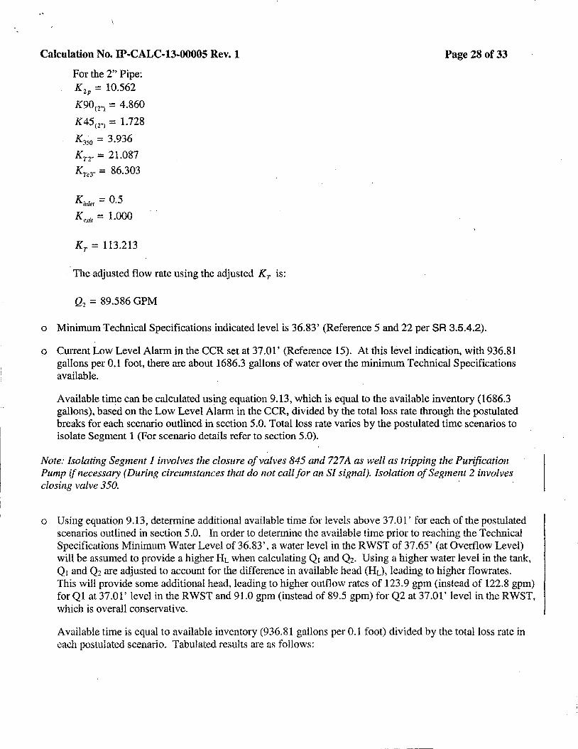
For the 2" Pipe: K 2P = 10.562
K90<Z"> = 4.860
K 45 <Z"> = 1. 728
K350 = 3.936
Kn .. = 21.087
KTeJ" = 86.303
Kirrlet = 0.5
Kexir = 1.000
Kr= 113.213
The adjusted flow rate using the adjusted Kr is:
Q2 = 89.586 GPM
Page 28of33
o Minimum Technical Specifications indicated level is 36.83' (Reference 5 and 22 per SR 3.5.4.2).
o Current Low Level Alarm in the CCR set at 37.01' (Reference 15). At this level indication, with 936.81 gallons per 0.1 foot, there are about 1686.3 gallons of water over the minimum Technical Specifications available. ·
Available time can be calculated using equation 9.13, which is equal to the available inventory (1686.3 gallons), based on the Low Level Alarm in the CCR, divided by the total loss rate through the postulated breaks for each scenario outlined in section 5.0. Total loss rate varies by the postulated time scenarios to isolate Segment 1 (For scenario detai.ls refer to section 5.0).
Note: Isolating Segment 1 involves the closure of valves 845 and 727 A as well as tripping the Purification Pump if necessary (During circumstances that do not call for an SI signal). Isolation of Segment 2 involves ~~~~~ '
o Using equation 9.13, determine additional available time for levels above 37.0 l' for each of the postulated scenarios outlined in section 5.0. In order to determine the available time prior to reaching the Technical Specifications Minimum Water Level of 36.83', a water level in the RWST of 37 .65' (at Overflow Level) will be assumed to provide a higher HL when calculating Q1 and Q2• Using a higher water level in the tank, Q1 and Q2 are adjusted to account for the difference in available head (HL), leading lo higher flowrates. This will provide some additional head, leading to higher outflow rates of 123.9 gpm (instead of 122.8 gpm) for Ql at 37.01' level in the RWST and 91.0 gpm (instead of 89.5 gpm) for Q2 at 37.01' level in the RWST, which is overall conservative.
Available time is equal to available inventory (936.81 gallons per 0.1 foot) divided by the total loss rate in each postulated scenario. Tabulated results are as follows:
,.
Calculation No. IP-CALC-13-00005 Rev.1
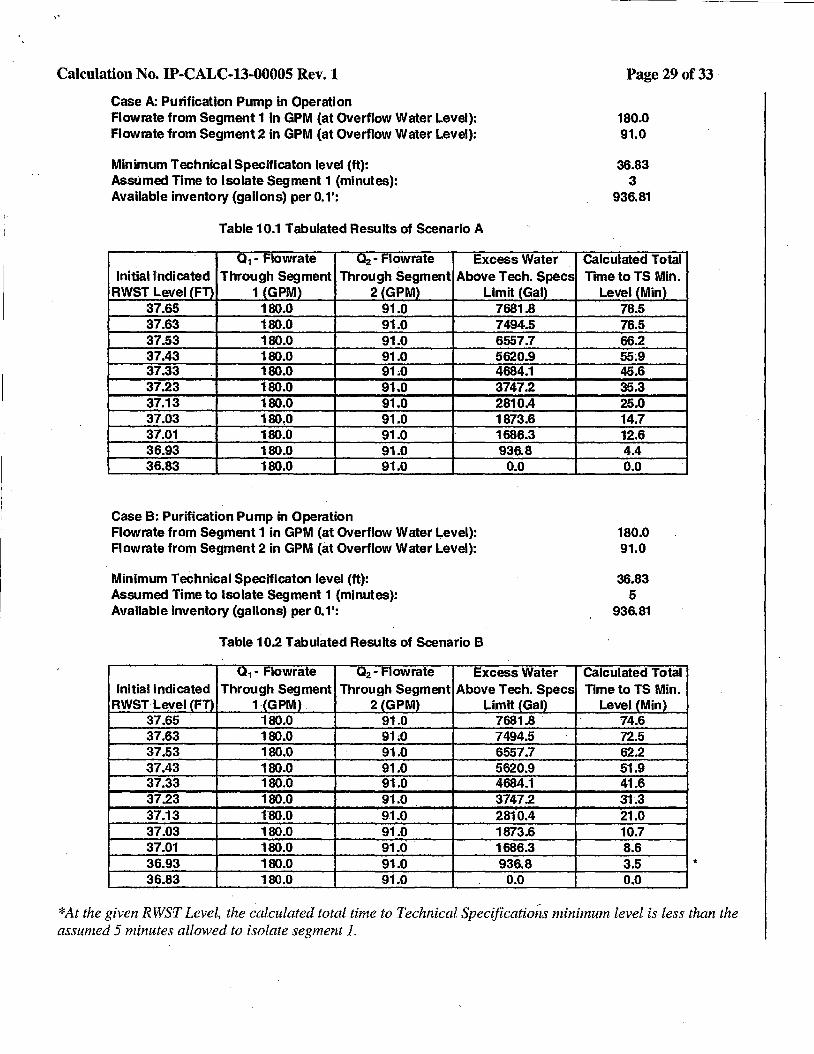
Case A: Purification Pump in Operation Flowrate from Segment 1 in GPM (at Overflow Water Level): Flowrate from Segment 2 in GPM (at Overflow Water Level):
Minimum Technical Specificaton level (ft): Assumed Time to Isolate Segment 1 (minutes): Available inventory (gallons) per 0.1':
Table 10.1 Tabulated Results of Scenario A
Q 1 - Flowrate Q2 - Flowrate Excess Water Initial Indicated Through Segment Through Segment Above Tech. Specs
RWST Level (FT) 1 (GPM) 2 (GPM) Limit (Gal) 37.65 180.0 91.0 7681.8 37.63 180.0 91.0 7494.5 37.53 180.0 91.0 6557.7 37.43 180.0 91.0 5620.9 37.33 180.0 91.0 4684.1 37.23 180.0 91.0 3747.2 37.13 180.0 91.0 2810.4 37.03 180.0 91.0 1873.6 37.01 180.0 91.0 1686.3 36.93 180.0 91.0 936.8 36.83 180.0 91.0 0.0
Case B: Purification Pump in Operation Flowrate from Segment 1 in GPM (at Overflow Water Level): Flowrate from Segment 2 in GPM (at Overflow Water Level):
Minimum Teehnical Specificaton level (ft): Assumed Time to Isolate Segment 1 {minutes): Available inventory (gallons) per 0.1':
Table 10.2 Tabulated Results of Scenario B
Q 1 - Flowrate Q 2 - Flowrate Excess Water Initial Indicated Through Segment Through Segment Above Tech. Specs
RWST Level (FT) 1·(GPM) 2(GPM) Limit (Gal) 37.65 180.0 91.0 7681.8 . 37.63 180.0 91;0 7494.5 37.53 180.0 91.0 6557.7 37.43 180.0 91.0 5620.9 37.33 180.0 91.0 4684.1 37.23 180.0 91.0 3747.2 37.13 180.0 91.0 2810.4 37.03 180.0 91.0 1873.6 37.01 180.0 91.0 1686.3 36.93 180.0 91.0 936.8 36.83 180.0 91.0 0.0
Page 29of33
180.0 91.0
36.83 3
936.81
Calculated Total Time to TS Min.
Level (Min) 78.5 76.5 66.2 55~9
45.6 35.3 25.0 14.7 12.6 4.4 0.0
180.0 91.0
36.83 5
936.81
Calculated Total Time to TS Min.
Level (Min) 74.6 72.5 62.2 51.9 41.6 31.3 21.0 10.7 8.6 3.5 0.0
*
*At the given RWS,T Level, the ~alculated total time to Technical Specifications minimum level is less than the assumed 5 minutes allowed to isolate segment I.

Calculation No. IP-CALC-13-00005 Rev. 1
Case C: All Three SI Pumps in Operation Flowrate from Segment 1 in GPM (at Overflow Water Level): Flowrate from Segment 2 In GPM (at Overflow Water Level):
Minimum Technical Speciflcaton level (ft): Assumed Time to Isolate Segment 1 (minutes): Available inventory (gallons) per 0.1':
I
Table 10.4 Tabulated Results of Scenario C
U1 - t'IOWrate "'2 • t'IOWrate Excess Water Initial Indicated Through Segment Through Segment Above Tech. Specs
RWST Level CFn 1 (GPM) 2(GPM) Limit {Gal) '37.65 123.9 99.0 7681.8 37.63 123.9 99.0 - 7494.5 37.53 123.9 99.0 6557.7 37.43 123.9 99.0 5620.9 37.33 123.9 99.0 4684.1 37.23 123.9 99.0 3747.2 37.13 123.9 99.0' 2810.4 37.03 123.9 99.0 1873.6 37.01
/
123.9 99.0 1686.3 36.93 123.9 99.0 936.8 36.83 - 123.9 99.0 0.0
Case D: All Three SI Pumps in Operation Flowrate from Segment 1 in GPM {at Overflow Water Level): Flowrate from Segment 2 in GPM {at Overflow Water Level):
Minimum Technical SpecHlcaton level {ft): Assumed Time to Isolate Segment 1 (minutes): Available inventory {gallons) per 0.1':
Table 10.5 Tabulated Results of Scenario D
01 - Flowrate 0 2 - Flow rate Excess Water Initial Indicated Through Segment Through Segment Above Tech. Specs
RWST Level CFTl 1 CGPMl 2 (GPM) - Limit (Gal) 37.65 123.9 99.0 7681.8 37.63 123.9 99.0 7494.5 37.53 123.9 99.0 6557.7 37.43 123.9 99.0 5620.9 37.33 123.9 99.0 4684.1 37.23 123.9 99.0 3747.2 37.13 123.9 99.0 2810.4
. 37.03 123.9 99.0 1873.6 37.01 123.9 99.0 1686.3
I
36.93 123.9 99.0 936.8 36.83 123.9 99.0 o.o
Page 30of33
123.9 99.0
36.83 3
936.81
calculated Total Time to TS Min.
Level {Min) 73.8 71.9 62.5 53.0 43.6 34.1 24.6 15.2 13.3 5.7 0.0
123.9 99.0
36.83 5
936.81
Calculated Total Time to TS Min.
Level (Min} 71.3 69.4 60.0 50.5 41.1 31.6 22.1 12.7 10.8 4.2 0.0
*
*At the given RWST Level, the calculated total time to Technical Specifications minimum level is less than the assumed 5 minutes allowed to isolate segment I.
..
Calculation No. IP-CALC-13-00005 Rev.1 Page 31 of33
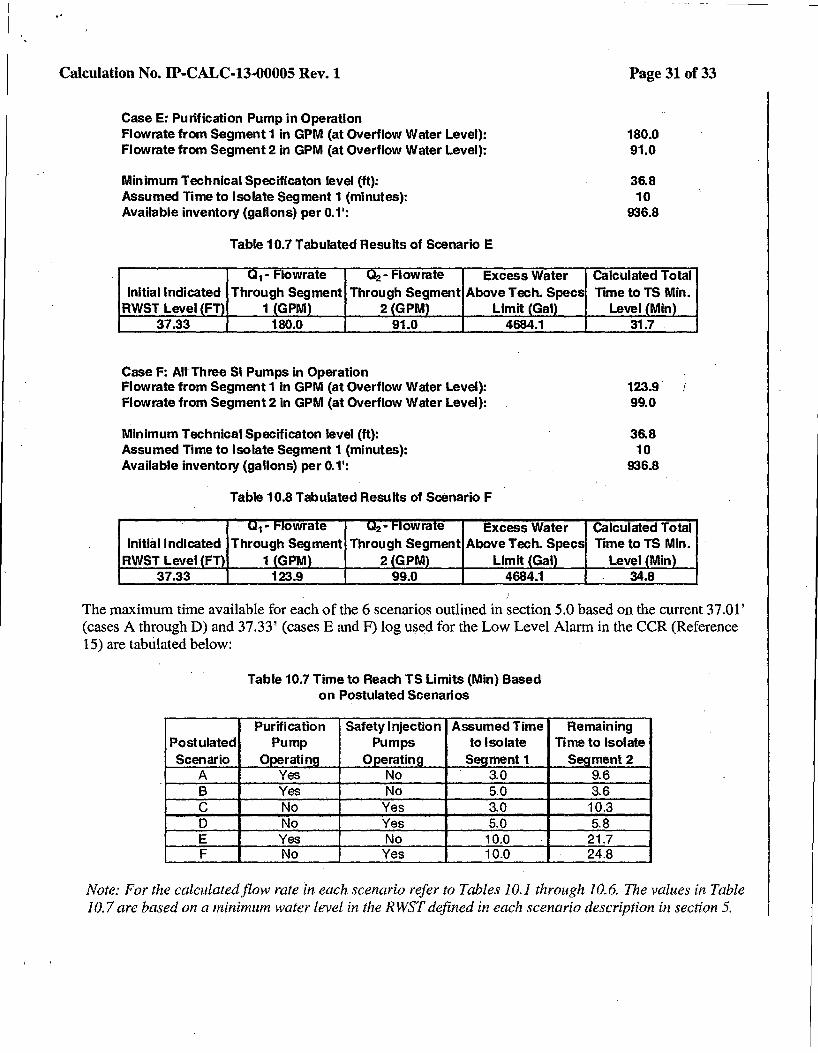
Case E: Purification Pump in Operation Flowrate from Segment 1 in GPM (at Overflow Water Level): Flowrate from Segment 2 in GPM {at Overflow Water Level):
Minimum Technical Specificaton level (ft): Assumed Time to Isolate Segment 1 (minutes): Available inventory (gallons) per 0.1':
Initial Indicated RWST Level FT
37.33
Table 10.7 Tabulated Reslilts of Scenario E
1 - lowrate - owrate Excess Water Through Segment Through Segment Above Tech. Specs
1 GPM 2 GPM Limit Gal 180.0 91.0 4684.1
Case F: All Three SI Pumps in Operation Flowrate from Segment 1 In GPM (at Overflow Water Level): Flowrate from Segment 2 in GPM (at Overflow Water Level):
Minimum Technical Specificaton level (ft): Assumed Time to Isolate Segment 1 (minutes): Available inventory {gallons) per 0. 1':
Initial Indicated RWST Level FT
37.33
Table 10.8 Tabulated Results of Scenario F
1 - owra e 2 - owra e Excess Water Through Segment Through Segment Above Tech. Specs
1 GPM 2 GPM Limit Gal 123.9 99.0 4684.1
180.0 91.0
36.8 10
936.8
Calculated Total Time to TS Min.
Level Min 31.7
123.9 99.0
36.8 10
936.8
Calculated Total Time to TS Min.
Level Min 34.8
The maximum time available for each of the 6 scenarios outlined in section 5.0 based on the current 37 .01' (cases A through D) and 37.33' (cases E and F) log used for the Low Level Alarm in the CCR (Reference 15) are tabtilated below:
Table 10.7 Time to Reach TS Limits {Min} Based on Postulated Scenarios
Safety Injection Assumed Time Remaining Postulated Pumps to Isolate Time to Isolate Scenario 0 s ment 1 s rnent 2
A 3.0 9.6 B No 5.0 3.6 c No Yes 3.0 10.3 D No Yes 5.0 5.8 E Yes No 10.0 21.7 F No Yes 10.0 24.8
Note: For the calculated flow rate in each scenario refer to Tables 10.1through10.6. The values in Table 10.7 are based on a minimum water level in the RWST defined in each scenario description in section 5.
Calculation No. IP-CALC-13-00005 Rev.1
11.0 References
Page 32 of33
1. Drawing 9321-F-2633, Rev. 38, "Nuclear Tank Farm Composite Piping". 2. Drawing 9321-F-2570, Rev. 73, "Primary Auxiliary Building Composite Piping Arrangement". 3. Drawing 9321-F-2580, Rev. 30, "Primary Auxiliary Building Composite Piping Arrangement
Sections - Sheet No. 8". 4. Drawing IS0-253-A-2-1, Rev. 2, "Piping Isometrics - Line #252 + #253 Also Found Under
Indian Point 2". 5. Entergy Calculation FIX-00096-:01, "RWST - Level Instrumentation Channel Accuracies,
Calibration, and Setpoints". 6. Drawing 9321-F-2735, Rev.140, "Safety Injection System" UFSAR Figure No. 6.2-1 (Sht.1). 7. Drawing 9321-F-2736, Rev.129, "Chemical & Volume Control System- UFSAR },igure No. 9.2-
1 (SHT.1)". 8. Drawing A227781, Rev. 82, "Auxiliary Coolant System - UFSAR Figure No. 9.3-1 (SHT.1)". 9. Entergy Specification 9321-01-248-18, Rev. 19, "FabriCation of Piping Systems~ Turbine
Generator Plant". 10. Purchase Order No. 9-05664, Refueling Water Purification Pump #21. 11. Entergy Procedure 2-PT-Q029A, Rev. 24, "21 Safety Injection Pump". 12. Entergy Procedure 2-PT-Q029B, Rev. 20, "22 Safety Injection Pump". 13. Entergy Procedure 2-PT-Q029C, Rev. 21, "23 Safety Injection Pump". 14. Crane Technical Paper 410, 1982 Edition, "Flow of Fluid Through Valves, Fittings and Pipe". 15. Entergy Procedure 2-ARP-SBF-1, Rev. 41, "CCR Safeguards". 16. ITT Industries - Dia-Flo Industrial Diaphragm Valves Engineering Catalog •. 17. Drawing IP3V-354-0006, Rev. 3 "Stainless Steel Univalve Check Valve". 18. Vendor Manual 1775, Rev. 3, "Service Manual for Rockwell Edwards Univalves". 19. Entergy Calculation IP3-CALC-Sl-03333, Rev. 0, "Engineering Evaluation of postulated RWST
Inventory Loss in Support of ACT 99-44077". 20. Entergy Report IP-RPT-09-00014, Rev. 1, "Critical Submergence Evaluations Related to
Surface Vortices in Nuclear Safety and Augmented Quality Tanks/Pumps at IPEC". 21. ANSl/ASME Code B16.9, 1986 Edition, "Factory Made Wrought Steel Butt-welding Fittings". 22. Entergy Controlled Document - Technical Specifications, "Indian Point 2 Improved Technical
Specifications"
'\
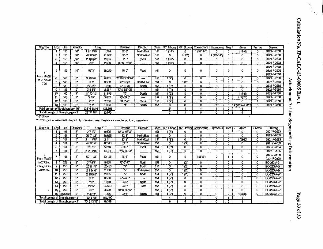
Sement Lea Line Diameter length Elevalioo Dir Edi on 1 155 16" 1' 811/16' 1.724 82'6" North'East 2 155 16" 41'05'8' 41.052 82'6" North/v\est 3 155 16" 2' 103'8" 2.665 82' 6" WfS. 4 155 16" 2'6'' 2.500 az 6'-76' er -
1 5 155 16" 88'3' 88250 76'0' WfS.
From RAISr 6 183 2" a 1031a· 0.865 76' 8" -77 9 3'8" to 2'' Valve -·-
725 7 183 2" err 0.583 7793/ff' S'.JuthlEast 8 183 2" 1' 2 518" 1.219 7793/ff' South 9 183 2'' 2' 33'8' 2.281 7793/8"·75' -10 183 2" 11' 10112'' 11.875 75' South 11 183 2" 2/ 10" 3.833 75'-00 6" -12 183' 2' 2'3' 2.250 69' 6"·71' WfS. 13 135 2'' 1' 1" 1.083 71' South
Total Lena n of Straiom nipe • 16" 136' 411116" 136.391 Total Lenath of Straight Dlce-2" 23' 117/8" 23.990
'14"EIOOW •• 1-2" Exi;ender ass lined to be part d purification purr-p. Resistanre is negla:ted for cooseivalisrn
Segment Lea Line Diarreter Lergth Elevalioo DirEdioo 1 161 3" 'J71iZ' 9.625 83' 3"-93' 3' ··-2 161 3" 36' 71/2'' 36.625 83' 3• North'East 3 161 3" 2' 111/16" 2.141 83'3' North'East 4 161 3" 4261/8" 42.510 83'3" North/V\est 5 161 3" f3 271W 5.240 83'3" WeS. 6 161 3' 6' 211/16" 6.224 76' 6"·83' 3" ·--
2 7 161 3" flJ 11/2'' 50.125 76' 6" WeS. From RAISr to2"~ind 8 253 2' (]7518" 0.635 776"-77 North
Flange Past 9 253 2" 32 51/4" 32.438 77 North Val\€350 10 253 2' 2' 1 ~16' 2.130 77 f'b1hMest
11 253 2'' 2105'8" 2.665 77 North 12 253 2." Cf 7' 0.583 77-94'6" ---13 253 2" 1'3' 1.250 94'6" North 14 253 ·2' 24'6" 24.500 94'6' Ba 15 253 2" 4'6" 4.500 94' 6"·006" -16 253252 2" 1' 43'4" 1.300 006" South
Total Len01 111 ofSraiantoioe-3" 152' 51/8" 152.490 Total Lenath of Sraiaht Dice- 2" 7fJ 31l'16" 70.318
Oass 00" Ellx:lws 45° 800\lls Contractions l->rnl'Y1Ar<:
151 1114"\ 0 1116"-14"l 0 151 0 1 (16"\ 0 1116"-14"\ 151 1116'1 0 0 0 151 1116"\ 0 0 0
151 0 0 0 0
151 112'\ 0 0 0 151 0 112"\ 0 0 151 1(2'\ 0 0 0 151 112'\ 0 0 0 151 112''1 0 0 0 151 112"\ 0 0 0 151 212'\ 0 0 0 151 0 0 a ,()*'
3* 1 1 1 7 1 0 0
Oass 00" Ellx:lws 45" Ellx:lws Contractions Elq::aiders 151 1 (3"1 0 0 0 151 0 0 0 0 151 1 (3") 0 0 0 151 0 1 (3") 0 0 151 1 (3") 0 0 0 151 1 (3") 0 0 0
151 0 0 1 (3"·2') 0
151 0 1 (2') 0 0 151 0 1 (2') 0 0 151 0 1 (2") 0 0 151 1 (2'') 1(2'~ 0 0 151 1 (2'') 0 0 0 151 1 (2") 0 0 0 151 1 (2") 0 0 0 151 1 (2") 0 0 0 151 1 (2") 0 0 0
4 1 1 0 6 4 0 0
Tees Valves Purrp; 0 118461 0 0 0 0 0 0 0 0 0 0
0 0 0
0 0 0 0 0 0 0 0 0 0 0 0 0 11845\ 0 0 11727A\ 0 0 0 1 0 2trd:il\& r.!!>J 0 0 1 0 4
Tees . Valves Punm 0 0 0 0 0 0 0 1 (1800) 0 0 0 0 0 0 0 0 0 0
1 0 0
0 0 0 0 0 0 0 0 0 0 0 0 0 0 0 0 0 0 0 0 0 0 0 0 0 1 (350) 0 1 1
' 0 1
' urawina 9321-F-2633 9321-F-2633 9321-F-2633 9321-F-2633 9321-F-2633 9321-F-2570 9321-F-2580 9321-F-2580 9321-F-2580 >
~ 9321-F-2580 9321-F-2580
~ =-9321-F-2580 s 9321-F-2580 9321-F-2580
rtl = ...... 9321-F-2580 !':"
~ .... = rtl r:r.i rtl
(JQ
lJraWing s 9321-J-·2633 9321·J--2trn 9321-F-2633 9321-F-2633
~ = t$ ('D
(JQ
9321-F-2634 9321-F-2635 9321-F-2633
...... = ~ "" 9321-F-2570 9
IID253-A-2-1 ~ ...... IID253-A-2-1 -· c IID253-A·2-1 = IS).253-A-2-1 IS0.253-A-2-1 IS0.253-A-2-1 IS0.253-A-2-1 IS0.253-A-2-1 IID253-A-2-1
D -a -~ .... .... c = ~ ,.... ~ (1
> ~ (1 I
'"'"" (,H I
Q Q Q Q (Ii
~ ~
'"'""
looC ~
~ (,H !...,)
s, (,H (,H
-(
~ ~·