Embed Size (px)
Citation preview
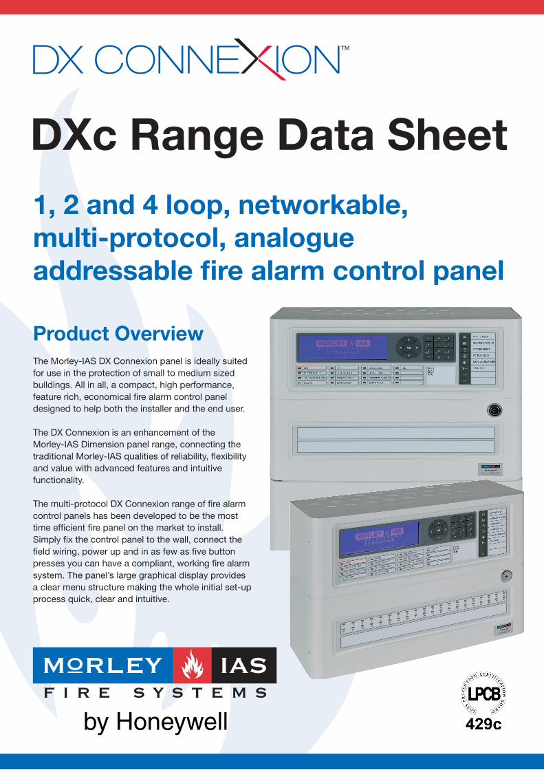
DXc Range Data Sheet1, 2 and 4 loop, networkable,multi-protocol, analogue addressable fi re alarm control panel
Product OverviewThe Morley-IAS DX Connexion panel is ideally suited for use in the protection of small to medium sized buildings. All in all, a compact, high performance, feature rich, economical fi re alarm control panel designed to help both the installer and the end user.
The DX Connexion is an enhancement of theMorley-IAS Dimension panel range, connecting the traditional Morley-IAS qualities of reliability, fl exibility and value with advanced features and intuitive functionality.
The multi-protocol DX Connexion range of fi re alarm control panels has been developed to be the most time effi cient fi re panel on the market to install. Simply fi x the control panel to the wall, connect the fi eld wiring, power up and in as few as fi ve button presses you can have a compliant, working fi re alarm system. The panel’s large graphical display provides a clear menu structure making the whole initial set-up process quick, clear and intuitive.
Product Overview (Continued...)Additionally, programming the control panel couldn’t be easier. Complex confi guration can be achieved by using either the panel’s mobile phone style key pad or by using the Windows PC programming tool supplied with the panel. The fl exible PC programming tool also allows text messages for devices or zones to be imported from an Excel spread sheet, saving further time. Panel Features
• Optional 40 or 80 zone alarm LEDs• Easy 5 key-press set-up• Large blue LCD display• Supports USB upload/download • Mobile phone style keypad and navigation keys• Option to upload a company logo
Software Features• PC confi guration software (supplied with panel)• 80 fi re zones (can be used with or without LEDs)• 7 day timers• Event logging• Onboard diagnostics• Class change function• Coincidence and verifi cation detection for false alarm management• Sensitivity adjustment e.g. between day and night• Input/output logic
Hardware Features• Battery backed real-time clock (2 & 4 loop)• 2 independent sounder circuits• 500mA multi-protocol loop driver • 2 x onboard monitored inputs• Optional programmable keyswitch for selected functions• Plug-in connectors
Output Relays:Fire relay: Single pole changeover 24V DC 1AFault relay: Single pole changeover 24V DC 1AAux relay: Programmable single pole changeover24V DC 1A
Onboard Data Ports:1 x RS485 (Repeater connection)1 x PC Programming Port4
Optional Ports:RS232 third party protocol interface
Sounder Circuits:2 output circuits, 1A per circuit.1
Networking Features• Network up to 16 loops (16x1 loop panels, 8x2 loop panels, 4x4 loop panels or any mix up to max 16 loops)• True peer-to-peer and fault tolerant network for high system reliability• BS5839 part 1 compliant network
User InterfaceDisplay 6x40 character (240x64 pixels) blue liquid crystal display with backlight illumination
Control Keys Evacuate, Silence/Resound, Mute Buzzer, Extend Delay, System Reset, Show Alarm Zones
Programmable 2 independent programmable function Keys keys and LED indicators
Programming 12 button alpha numeric key pad inc Keys cancel and return keys plus 4 navigation keys and an OK key
Indicators Fire, Fault, Disablement, Test, Buzzer Muted, Delayed Mode, Sounders Silenced, Sounders Disabled and Power. Also dedicated fault LEDs for System Fault, Supply Fault and Earth Fault. 40 or 80 LED fi re zone indicators optional.
Loop Capacity2: 500mA per loop
Protocol DevicesSupports Apollo (Xplorer, XP95 and Discovery), Hochiki (ESP) & System Sensor protocol devices.
Number of Apollo Hochiki SystemDevices Protocol Protocol Sensor Protocol
126 -
198 - -

Mechanical DXc1 DXc2 DXc4Dimensions [mm] (H x W x D) 260 x 390 x 147 391.5 x 390 x 147 391.5 x 390 x 147
Weight (Excluding Batteries) 4kg 4.5kg 4.5kg
Colour RAL 9002 - Grey white RAL 9002 - Grey white RAL 9002 - Grey white
Mounting Holes 3 3 3
Knockouts (20mm) Top: 25x Top: 25x Top: 25x Bottom: 2x Bottom: 4x Bottom: 4x
Operating Temperature 0°C to +40°C 0°C to +40°C 0°C to +40°C
Relative Humidity 5% - 95% non-condensing 5% - 95% non-condensing 5% - 95% non-condensing
IP30 (EN6059) IP30 (EN6059) IP30 (EN6059)
Material Mild steel sheet rear enclosure. ABS plastic front cover to BS EN60950. All displays and controls are carried on the enclosure door.
DXc1 DXc2 DXc4Operating Voltage 230V AC (+15%,-15%) 50-60 Hz 230V AC (+15%,-15%) 50-60 Hz 230V AC (+15%,-15%) 50-60 Hz
PSU Rating 24V DC 2A 24V DC 4A 24V DC 4A
Stand-by Batteries5 2 x 7Ah 2 x 17Ah 2 x 17Ah
Stand-by Battery Duration3 Stand alone: 24 hours Stand alone: 72 hours. Stand alone: 48 hours.(Based on Apollo devices) back-up with either With network card or With network card or network card or repeater repeater connected: repeater connected: connected 48 hours 24 hours
Auxilliary Output1 +24V DC 250mA fused +24V DC 250mA fused +24V DC 250mA fused
Notes:1 Maximum available current will be dependent on full control panel loading.2 Only one protocol can be selected within the control panel.3 Stand-by dependent on type and quantity of devices installed.4 Requires RS232 or USB interface lead.5 Not included.
Electrical
DXc1 / DXc2 / DXc4
DXc2 / DXc4
260
390
147
391.5
390

Part Numbers Accessories (continued)
795-114 Bezel kit DXc1 plus Extension Box795-115 Bezel kit DXc2/4 plus Extension Box795-116 Custom keyplate cover for Extension Box795-118 Keyswitch kit795-119 Rack mounting kit DXc1795-120 Rack mounting kit DXc2/4795-121 Extension back box795-122 RS232 Kit (for third party protocol)795-124 80 zone LED card kit020-891 USB isolated upload/download leadSee price list Visualeyez options
Charles Avenue
Burgess Hill
West Sussex
RH15 9UF UK
T: +44 (0) 1444 235 556
F: +44 (0) 1273 376 894
www.morley-ias.co.uk
For further details on these or any other Morley-IAS products please contact your local distributor, Morley-IAS Business Manager or via our contact details found below. Morley-IAS by Honeywell - Providing a control panel solution, for fi re industry professionals, committed to supporting our device partners.
DXc System Example
Every care has been taken in the preperation of this datasheet but no liability can be accepted for the use of the information therein. Design features may be changed or amended without prior notice.© Morley-IAS by Honeywell 2011
DO
C R
EF:
M10
0-D
Xc-
R1-
(051
1)
Panels714-001-111 DXc1 One loop Fire Alarm Control Panel714-001-221 DXc2 Two loop Fire Alarm Control Panel714-001-241 DXc4 Four loop Fire Alarm Control Panel
Accessories795-097 Engineers SPK (Software Programming Kit)
795-099 Network card795-101 Blank cover kit for Extension Box795-102 40 zone LED card kit795-111 2 loop expansion card795-112 Bezel kit for DXc1 (mm: h:342 x w:471.5 x d:13)
795-113 Bezel kit for DXc2/4 (mm: h:473.5 x w:471.5 x d:13)
* Images shown above with optional LED Kit