Embed Size (px)
Citation preview
DXMarginally lubricated
Designer´s Handbook
I
QualityAll the products described in this handbook are manufactured under DIN EN ISO 9001, ISO/TS 16949 and ISO 14001approved quality management systems.
II
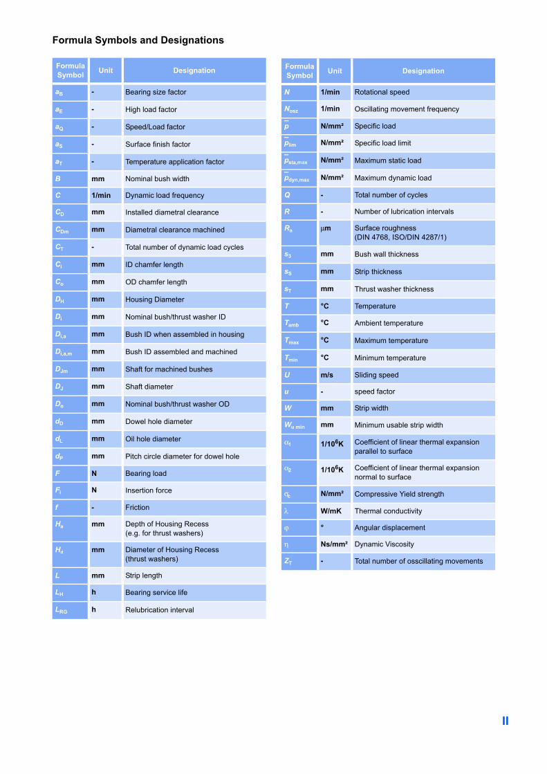
Formula Symbols and Designations
FormulaSymbol Unit Designation
aB - Bearing size factor
aE - High load factor
aQ - Speed/Load factor
aS - Surface finish factor
aT - Temperature application factor
B mm Nominal bush width
C 1/min Dynamic load frequency
CD mm Installed diametral clearance
CDm mm Diametral clearance machined
CT - Total number of dynamic load cycles
Ci mm ID chamfer length
Co mm OD chamfer length
DH mm Housing Diameter
Di mm Nominal bush/thrust washer ID
Di,a mm Bush ID when assembled in housing
Di,a,m mm Bush ID assembled and machined
DJm mm Shaft for machined bushes
DJ mm Shaft diameter
Do mm Nominal bush/thrust washer OD
dD mm Dowel hole diameter
dL mm Oil hole diameter
dP mm Pitch circle diameter for dowel hole
F N Bearing load
Fi N Insertion force
f - Friction
Ha mm Depth of Housing Recess(e.g. for thrust washers)
Hd mm Diameter of Housing Recess(thrust washers)
L mm Strip length
LH h Bearing service life
LRG h Relubrication interval
N 1/min Rotational speed
Nosz 1/min Oscillating movement frequency
p N/mm² Specific load
plim N/mm² Specific load limit
psta,max N/mm² Maximum static load
pdyn,max N/mm² Maximum dynamic load
Q - Total number of cycles
R - Number of lubrication intervals
Ra µm Surface roughness (DIN 4768, ISO/DIN 4287/1)
s3 mm Bush wall thickness
sS mm Strip thickness
sT mm Thrust washer thickness
T °C Temperature
Tamb °C Ambient temperature
Tmax °C Maximum temperature
Tmin °C Minimum temperature
U m/s Sliding speed
u - speed factor
W mm Strip width
Wu min mm Minimum usable strip width
α1 1/106K Coefficient of linear thermal expansion parallel to surface
α2 1/106K Coefficient of linear thermal expansion normal to surface
σc N/mm² Compressive Yield strength
λ W/mK Thermal conductivity
ϕ ° Angular displacement
η Ns/mm² Dynamic Viscosity
ZT - Total number of osscillating movements
FormulaSymbol Unit Designation

Content
3
ContentQuality . . . . . . . . . . . . . . . . . . . . . IFormula Symbolsand Designations . . . . . . . . . . . . . II
1 Introduction . . . . . . . . . . . 41.1 Characteristics
and Advantages . . . . . . . . . . . . . 4
2 Structure . . . . . . . . . . . . . 42.1 Basic Forms . . . . . . . . . . . . . . . . 5
3 Properties . . . . . . . . . . . . . 63.1 Physical Properties . . . . . . . . . . 63.2 Chemical Properties . . . . . . . . . 6
4 Lubrication . . . . . . . . . . . . 74.1 Choice of Lubricant . . . . . . . . . . 7
Grease . . . . . . . . . . . . . . . . . . . . . 8Oil . . . . . . . . . . . . . . . . . . . . . . . . 8Non lubricating fluids . . . . . . . . . . 8Water . . . . . . . . . . . . . . . . . . . . . . 8Water-Oil Emulsion . . . . . . . . . . . 8Shock-Absorber Oils . . . . . . . . . . 8Petrol . . . . . . . . . . . . . . . . . . . . . . 8Kerosene and Polybutene . . . . . . 8Other Fluids . . . . . . . . . . . . . . . . . 8
4.2 Friction . . . . . . . . . . . . . . . . . . . . 94.3 Lubricated Environments . . . . . 9
Lubrication . . . . . . . . . . . . . . . . . . 94.4 Characteristics of Fluid
Lubricated DX Bearings . . . . . 104.5 Design Guidance for Fluid
Lubricated Applications . . . . . 104.6 Wear Rate and
Relubrication Intervalswith Grease lubrication . . . . . . 12Fretting Wear . . . . . . . . . . . . . . . 12
5 Design Factors . . . . . . . 135.1 Specific Load . . . . . . . . . . . . . . 13
Specific Load Limit . . . . . . . . . . . 135.2 Sliding Speed . . . . . . . . . . . . . . 14
Continuous Rotation . . . . . . . . . 14Oscillating Movement . . . . . . . . 14
5.3 pU Factor . . . . . . . . . . . . . . . . . 155.4 Load . . . . . . . . . . . . . . . . . . . . . 15
Type of Load . . . . . . . . . . . . . . . 155.5 Temperature . . . . . . . . . . . . . . . 175.6 Mating Surface . . . . . . . . . . . . . 175.7 Bearing Size . . . . . . . . . . . . . . . 185.8 Estimation of Bearing Service
Life with Grease Lubrication . 18
5.9 Worked Examples . . . . . . . . . . 20
6 Data Sheet . . . . . . . . . . . 216.1 Data for bearing
design calculations . . . . . . . . . 21
7 Bearing Assembly . . . . . 227.1 Dimensions and Tolerances . . 227.2 Tolerances for
minimum clearance . . . . . . . . . 22Grease lubrication . . . . . . . . . . . 22Fluid Lubrication . . . . . . . . . . . . . 24Allowance forThermal Expansion . . . . . . . . . . 24
7.3 Counterface Design . . . . . . . . . 257.4 Installation . . . . . . . . . . . . . . . . 26
Fitting of Bushes . . . . . . . . . . . . 26Insertion Forces . . . . . . . . . . . . . 26Alignment . . . . . . . . . . . . . . . . . . 27Sealing . . . . . . . . . . . . . . . . . . . . 27Axial Location . . . . . . . . . . . . . . . 27Fitting of Thrust Washers . . . . . . 27Slideways . . . . . . . . . . . . . . . . . . 28
8 Machining . . . . . . . . . . . 298.1 Machining Practice . . . . . . . . . 298.2 Boring . . . . . . . . . . . . . . . . . . . . 298.3 Reaming . . . . . . . . . . . . . . . . . . 308.4 Broaching . . . . . . . . . . . . . . . . . 308.5 Vibrobroaching . . . . . . . . . . . . . 318.6 Modification of components . . 318.7 Drilling Oil Holes . . . . . . . . . . . 318.8 Cutting Strip Material . . . . . . . . 31
9 Electroplating . . . . . . . . 32DX Components . . . . . . . . . . . . . 32Mating Surfaces . . . . . . . . . . . . . 32
10 Standard Products . . . . 3310.1 PM-DX cylindrical bushes . . . . 3310.2 MB-DX cylindrical bushes . . . . 4010.3 DX Thrust Washers . . . . . . . . . 4510.4 DX cylindrical bushes -
Inch sizes . . . . . . . . . . . . . . . . . 4610.5 DX Thrust Washers -
Inch sizes . . . . . . . . . . . . . . . . . 4910.6 DX Strip . . . . . . . . . . . . . . . . . . . 5010.7 DX Strip - Inch sizes . . . . . . . . . 50
4
1 Introduction
1 IntroductionThe purpose of this handbook is to providecomprehensive technical information onthe characteristics of DX® bearings. Theinformation given, permits designers toestablish the correct size of bearingrequired and the expected life and per-formance. GGB Research and Develop-ment services are available to assist withunusual design problems.
Complete information on the range of DXstandard stock products is given togetherwith details of other DX products.GGB is continually refining and extendingits experimental and theoretical knowledgeand, therefore, when using this brochure itis always worthwhile to contact the Com-pany should additional information berequired. Customers are advised to carry out proto-type testing wherever possible.
1.1 Characteristics and Advantages• DX provides maintenance free
operation• DX has a high pU capability• DX exhibits low wear rate• Seizure resistant• Suitable for temperatures from
-40 to +120 °C• High static and dynamic load capacity
• Good frictional properties• No water absorption and therefore
dimensionally stable• Compact and light• Suitable for rotating, oscillating,
reciprocating and sliding movements• DX bearings are prefinished and
require no machining after assembly
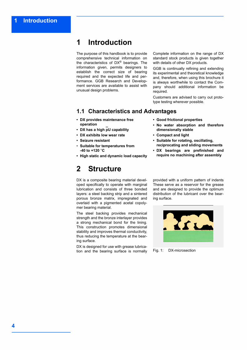
2 StructureDX is a composite bearing material devel-oped specifically to operate with marginallubrication and consists of three bondedlayers: a steel backing strip and a sinteredporous bronze matrix, impregnated andoverlaid with a pigmented acetal copoly-mer bearing material.The steel backing provides mechanicalstrength and the bronze interlayer providesa strong mechanical bond for the lining.This construction promotes dimensionalstability and improves thermal conductivity,thus reducing the temperature at the bear-ing surface. DX is designed for use with grease lubrica-tion and the bearing surface is normally
provided with a uniform pattern of indentsThese serve as a reservoir for the greaseand are designed to provide the optimumdistribution of the lubricant over the bear-ing surface.
Fig. 1: DX-microsection
5
2Structure
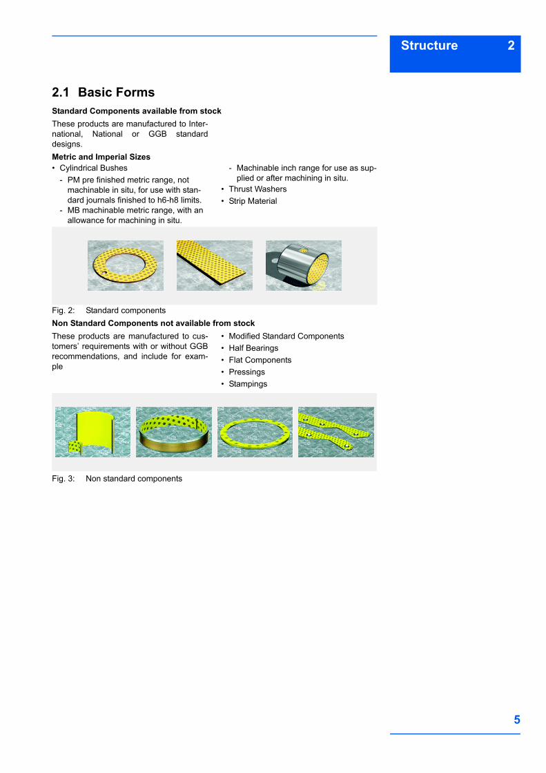
2.1 Basic FormsStandard Components available from stockThese products are manufactured to Inter-national, National or GGB standarddesigns.Metric and Imperial Sizes• Cylindrical Bushes
- PM pre finished metric range, not machinable in situ, for use with stan-dard journals finished to h6-h8 limits.
- MB machinable metric range, with an allowance for machining in situ.
- Machinable inch range for use as sup-plied or after machining in situ.
• Thrust Washers• Strip Material
Fig. 2: Standard componentsNon Standard Components not available from stockThese products are manufactured to cus-tomers’ requirements with or without GGBrecommendations, and include for exam-ple
• Modified Standard Components• Half Bearings• Flat Components• Pressings• Stampings
Fig. 3: Non standard components

6
3 Properties
3 Properties3.1 Physical Properties
Table 1: Properties of DX
3.2 Chemical PropertiesThe following table provides an indicationof the resistance of DX to various chemicalmedia. It is recommended that the chemi-
cal resistance is confirmed by testing ifpossiple.
Table 2: Chemical resistance of DX
Characteristic Symbol Value DX Unit Comments
Physical Properties
Thermal Conductivity λ 52 W/mK
Coefficient of linear thermal expansion
parallel to surface α1 11 1/106K
normal to surface α2 29 1/106K
Maximum Operating Temperature Tmax 120 °C
Minimum Operating Temperature Tmin –40 °C
MechanicalProperties Compressive Yield Strength σc 380 N/mm² measured on disc 5 mm dia-
meter x 2.45 mm thick.
Maximum Load
Static psta,max 140 N/mm²
Dynamic pdyn,max 70 N/mm²
Electrical Properties Volume resistivity of acetal lining 1015 Ωcm
Chemical % °C Rating
Strong Acids Hydrochloric Acid 5 20 -Nitric Acid 5 20 -Sulphuric Acid 5 20 -
Weak Acids Acetic Acid 5 20 -Formic Acid 5 20 -
Bases Ammonia 10 20 oSodium Hydroxide 5 20 o
Solvents Acetone 20 +Carbon Tetrachloride 20 +
Lubricants and fuels Paraffin 20 +Gasolene 20 +Kerosene 20 +Diesel fuel 20 +Mineral Oil 70 oHFA-ISO46 High Water fluid 70 oHFC-Water-Glycol 70 oHFD-Phosphate Ester 70 +Water 20 oSea Water 20 -
+Satisfactory: Corrosion damage is unlikely to occur.
o
Acceptable: Some corrosion damage may occur but this will not be suf-ficient to impair either the structural integrity or the tribo-logical performance of the material.
-
Unsatisfactory: Corrosion damage will occur and is likely to affect either the structural integrity and/or the tribological performance of the material.
7
4Lubrication
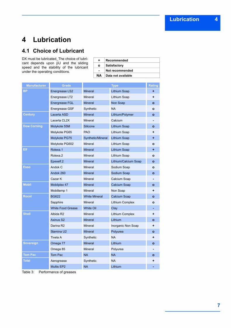
4 Lubrication4.1 Choice of LubricantDX must be lubricated. The choice of lubri-cant depends upon pU and the slidingspeed and the stability of the lubricantunder the operating conditions.
Table 3: Performance of greases
+ Recommendedo Satisfactory- Not recommended
NA Data not available
Manufacturer Grade Type Rating
BP Energrease LS2 Mineral Lithium Soap +Energrease LT2 Mineral Lithium Soap +Energrease FGL Mineral Non Soap oEnergrease GSF Synthetic NA o
Century Lacerta ASD Mineral Lithium/Polymer oLacerta CL2X Mineral Calcium -
Dow Corning Molykote 55M Silicone Lithium Soap oMolykote PG65 PAO Lithium Soap +Molykote PG75 Synthetic/Mineral Lithium Soap +Molykote PG602 Mineral Lithium Soap o
Elf Rolexa.1 Mineral Lithium Soap +Rolexa.2 Mineral Lithium Soap oEpexelf.2 Mineral Lithium/Calcium Soap o
Esso Andok C Mineral Sodium Soap oAndok 260 Mineral Sodium Soap oCazar K Mineral Calcium Soap -
Mobil Mobilplex 47 Mineral Calcium Soap oMobiltemp 1 Mineral Non Soap +
Rocol BG622 White Mineral Calcium Soap oSapphire Mineral Lithium Complex oWhite Food Grease White Oil Clay -
Shell Albida R2 Mineral Lithium Complex +Axinus S2 Mineral Lithium oDarina R2 Mineral Inorganic Non Soap +Stamina U2 Mineral Polyurea oTivela A Synthetic NA +
Sovereign Omega 77 Mineral Lithium oOmega 85 Mineral Polyurea -
Tom Pac Tom Pac NA NA oTotal Aerogrease Synthetic NA +
Multis EP2 NA Lithium -
8
4 Lubrication
GreaseGrease lubrication is the recommendedmethod of lubrication. The performanceratings of different types of grease are indi-cated in Table 3. For environmental tem-peratures above 50 °C the grease should
contain an anti-oxidant additive. Greasescontaining EP additives or significant addi-tions of graphite or MoS2 are not generallyrecommended for use with DX.
OilDX is not generally suitable for use withhydrocarbon oils operating above 115 °C.At these temperatures oxidation of the oilmay produce a low concentration of labileresidues, acid or free radical, which willcause depolymerisation of the DX acetalcopolymer bearing lining. Such oxidation
can also occur after prolonged periods atlower temperatures. In practice, thismeans that DX is not recommended foruse with recirculating oil systems or bathsystems where sump temperatures of70 °C or greater are possible.
Non lubricating fluidsCare must be taken when using DX withnon lubricating fluids as indicated below.
WaterDX is only suitable for operation in waterwhen the load and speed permit full hydro-
dynamic conditions to be established (seeFig. 7).
Water-Oil EmulsionDX is suitable for use with 95/5 water/oilemulsions, however initial operation with
pure oil or grease is recommended beforetransferring to emulsion.
Shock-Absorber OilsDX is not compatible with shock-absorberoils at operating temperature.
PetrolWith petrol as a lubricant at a pU factor of0.21 N/mm² x m/s the wear rate of DX hasbeen found to be about 4-5 times greater
than that of an initially greased bearingunder the same pU conditions.
Kerosene and PolybuteneThe wear rate of DX with these fluids hasbeen found to be equivalent to thatobtained with a light hydrocarbon oil.
Other FluidsPolyester, polyethylene glycol and polygly-col lubricants give similar wear rates withDX to light hydrocarbon oil. With the glycolfluids however the operating temperaturemust not exceed 80 °C because the acetallining of DX could then be attacked bythese fluids.In general, the fluid will be acceptable if itdoes not chemically attack the acetal liningor the porous bronze interlayer. Chemicalresistance data are given in Table 2.Where there is doubt about the suitabilityof a fluid, a simple test is to submerge a
sample of DX material in the fluid for two tothree weeks at 15-20 °C above the operat-ing temperature. The following will usuallyindicate that the fluid is not suitable for usewith DX.• A significant change in the thickness of
the DX material.• A visible change in the bearing surface
from polished to matt.• A visible change in the microstructure of
the bronze interlayer.
9
4Lubrication
4.2 FrictionLubricated DX bearings show negligible‘stick-slip’ and provide smooth slidingbetween adjacent surfaces. The coefficientof friction of lubricated DX depends upon
the actual operating conditions as indi-cated in section 4.3. Where frictional char-acteristics are critical to a design theyshould be established by prototype testing.
4.3 Lubricated EnvironmentsThe following sections describe the basicsof lubrication and provide guidance on theapplication of DX in such environments.
Lubrication There are three modes of lubricated bear-ing operation which relate to the thicknessof the developed lubricant film between thebearing and the mating surface.These three modes of operation dependupon:
• Bearing dimensions• Clearance• Load and Speed• Lubricant Viscosity and Flow
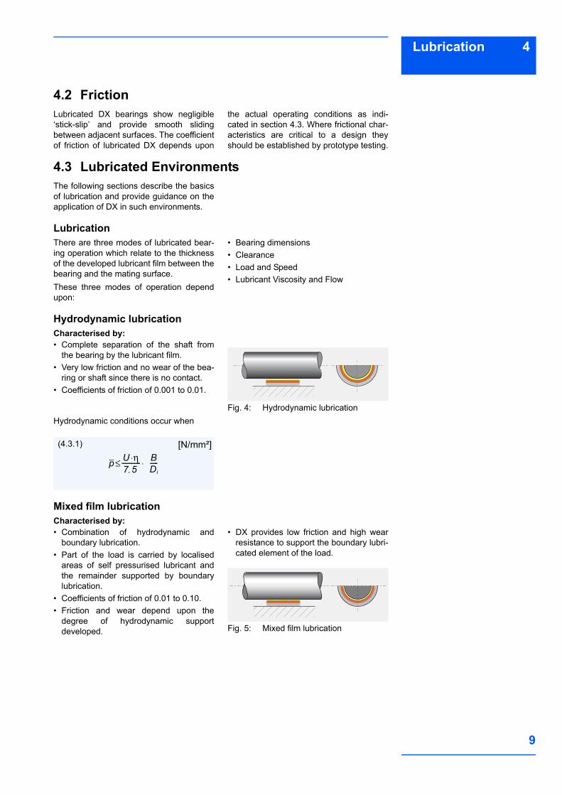
Hydrodynamic lubrication Characterised by:• Complete separation of the shaft from
the bearing by the lubricant film.• Very low friction and no wear of the bea-
ring or shaft since there is no contact.• Coefficients of friction of 0.001 to 0.01.
Fig. 4: Hydrodynamic lubricationHydrodynamic conditions occur when
Mixed film lubricationCharacterised by:• Combination of hydrodynamic and
boundary lubrication.• Part of the load is carried by localised
areas of self pressurised lubricant andthe remainder supported by boundarylubrication.
• Coefficients of friction of 0.01 to 0.10.• Friction and wear depend upon the
degree of hydrodynamic supportdeveloped.
• DX provides low friction and high wearresistance to support the boundary lubri-cated element of the load.
Fig. 5: Mixed film lubrication
p U η⋅7·5------------ B
Di-----⋅≤
(4.3.1) [N/mm²]

10
4 Lubrication
Boundary lubrication Characterised by:• Rubbing of the shaft against the bearing
with virtually no lubricant separating thetwo surfaces.
• Bearing material selection is critical toperformance.
• Shaft wear is likely due to contact bet-ween bearing and shaft.
• The excellent properties of DX materialminimises wear under these conditions.
• The dynamic coefficient of friction withDX is typically 0.02 to 0.1 under bound-ary lubrication conditions.
• The static coefficient of friction with DX istypically 0.03 to 0.15 under boundarylubrication conditions.
Fig. 6: Boundary lubrication
4.4 Characteristics of Fluid Lubricated DX BearingsDX is particularly effective in the mostdemanding of lubricated applications
where full hydrodynamic operation cannotbe maintained, for example:
• High load conditionsIn highly loaded applications operating under boundary or mixed film conditions DX shows excellent wear resistance and low friction.
• Start up and shut down under loadWith insufficient speed to generate a hydrodynamic film the bearing will ope-rate under boundary or mixed film condi-tions.- DX minimises wear- DX requires less start up torque than
conventional metallic bearings.
• Sparse lubricationMany applications require the bearing to operate with less than the ideal lubricant supply, typically with splash or mist lubri-cation only. DX requires significantly less lubricant than conventional metallic bea-rings.
4.5 Design Guidance for Fluid Lubricated Applications
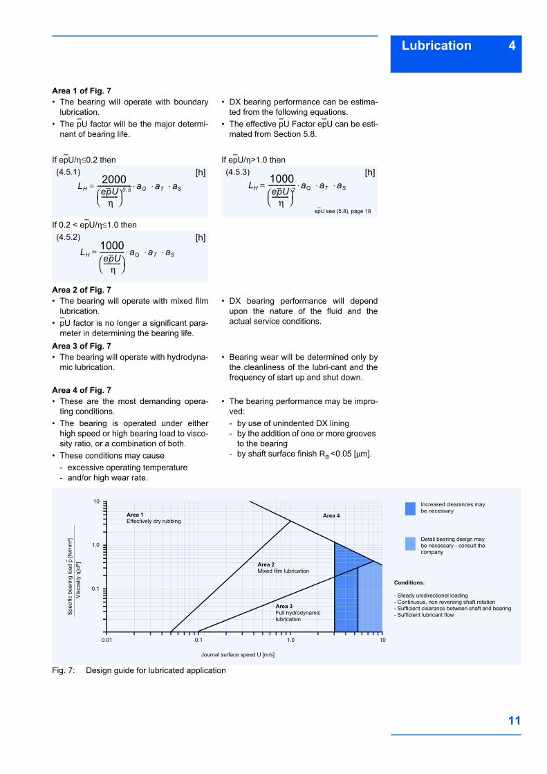
Fig. 7, Page 11 shows the three lubricationregimes discussed above plotted on a
graph of sliding speed vs the ratio of spe-cific load to lubricant viscosity.
In order to use Fig. 7• Using the formulae in Section 5
- Calculate the specific load p- Calculate the shaft surface speed(U)
• Using the viscosity temperature relati-onships presented in Table 4.- Determine the viscosity in centipoise
of the lubricant. Note:Viscosity is a function of the operating tem-perature. If the operating temperature of
the fluid is unknown, a provisional temper-ature of 25 °C above ambient can be used.
11
4Lubrication
Area 1 of Fig. 7• The bearing will operate with boundary
lubrication.• The pU factor will be the major determi-
nant of bearing life.
• DX bearing performance can be estima-ted from the following equations.
• The effective pU Factor epU can be esti-mated from Section 5.8.
If epU/η ≤0.2 then
If 0.2 < epU/η ≤1.0 then
If epU/η >1.0 then
Area 2 of Fig. 7• The bearing will operate with mixed film
lubrication.• pU factor is no longer a significant para-
meter in determining the bearing life.
• DX bearing performance will dependupon the nature of the fluid and theactual service conditions.
Area 3 of Fig. 7• The bearing will operate with hydrodyna-
mic lubrication.• Bearing wear will be determined only by
the cleanliness of the lubri-cant and thefrequency of start up and shut down.
Area 4 of Fig. 7• These are the most demanding opera-
ting conditions.• The bearing is operated under either
high speed or high bearing load to visco-sity ratio, or a combination of both.
• These conditions may cause- excessive operating temperature- and/or high wear rate.
• The bearing performance may be impro-ved:- by use of unindented DX lining- by the addition of one or more grooves
to the bearing- by shaft surface finish Ra <0.05 [µm].
Fig. 7: Design guide for lubricated application
(4.5.1) [h]LH
2000epU
η-----------⎝ ⎠
⎛ ⎞0·5---------------------- aQ aT aS⋅ ⋅ ⋅=
(4.5.2) [h]LH
1000epU
η-----------⎝ ⎠
⎛ ⎞---------------- aQ aT aS⋅ ⋅ ⋅=
(4.5.3) [h]LH
1000epU
η-----------⎝ ⎠
⎛ ⎞2------------------ aQ aT aS⋅ ⋅ ⋅=
epU see (5.8), page 18
Spec
ific
bear
ing
load
p [N
/mm
²]
Journal surface speed U [m/s]
0.1
1.0
10
0.01 0.1 1.0 10
Increased clearances may be necessary
Detail bearing design may be necessary - consult the company
Area 1Effectively dry rubbing
Area 2Mixed film lubrication
Area 3Full hydrodynamic lubrication
Area 4
Vis
cosi
ty η
[cP
]
Conditions:
- Steady unidirectional loading- Continuous, non reversing shaft rotation- Sufficient clearance between shaft and bearing- Sufficient lubricant flow

12
4 Lubrication
Table 4: Viscosity data
4.6 Wear Rate and Relubrication Intervals with Grease lubrication
At specific bearing loads below 100 N/mm²a grease lubricated DX bearing shows onlysmall bedding-in wear of about0.0025 mm. This is followed by little wearduring the early part of the bearing life untilthe lubricant becomes exhausted and thewear rate increases. If the bearing isregreased before the rate of wear starts toincrease rapidly the material will continueto function satisfactorily with little wear.Fig. 8 shows the typical wear pattern.
Under specific loads above 100 N/mm² theinitial bedding-in wear is greater, typicallyabout 0.025 mm, followed by a decreasingwear rate until the bearing exhibits a simi-lar wear/life relationship to that shown inFig. 8.The useful life of the bearing is limited bywear in the loaded area. If this wearexceeds 0.15 mm the grease capacity ofthe indents is reduced and more frequentregreasing of the bearing will be required.
Fretting WearOscillating movements of less than thedimensions of the indent pattern maycause localised wear of the mating surfaceafter prolonged usage. This will result inthe indent pattern becoming transferred
onto the mating surface in contact with theDX bearing and may also give rise to fret-ting corrosion damage. In this situationDSTM material should be considered as analternative to DX.
Fig. 8: Typical wear of DX
cPTemperature [°C] 0 10 20 30 40 50 60 70 80 90 100 110 120 130 140
LubricantISO VG 32 310 146 77 44 27 18 13 9.3 7.0 5.5 4.4 3.6 3.0 2.5 2.2
ISO VG 46 570 247 121 67 40 25 17 12 9.0 6.9 5.4 4.4 3.6 3.0 2.6
ISO VG 68 940 395 190 102 59 37 24 17 12 9.3 7.2 5.8 4.7 3.9 3.3
ISO VG 100 2110 780 335 164 89 52 33 22 15 11.3 8.6 6.7 5.3 4.3 3.6
ISO VG 150 3600 1290 540 255 134 77 48 31 21 15 11 8.8 7.0 5.6 4.6
Diesel oil 4.6 4.0 3.4 3.0 2.6 2.3 2.0 1.7 1.4 1.1 0.95
Petrol 0.6 0.56 0.52 0.48 0.44 0.40 0.36 0.33 0.31
Kerosene 2.0 1.7 1.5 1.3 1.1 0.95 0.85 0.75 0.65 0.60 0.55
Water 1.79 1.30 1.0 0.84 0.69 0.55 0.48 0.41 0.34 0.32 0.28
Rad
ial w
ear [
mm
]
Operating life
B
0.05
0.10
B B
Recommended re-greasing interval
End of useful life of pre-lubricated bearing - A
Initial greasing only
Recommended regreasing interval
Bearing continues with low rate of wear when regreased at intervals - B
13
5Design Factors
5 Design FactorsThe main parameters when determiningthe size or calculating the service life for aDX bearing are:• Specific Load Limit plim [N/mm²]• pU Factor [N/mm² x m/s]
• Mating surface roughness Ra [µm]• Mating surface material• Temperature T [°C]• Other environmental factors eg. housing
design, dirt, lubrication.
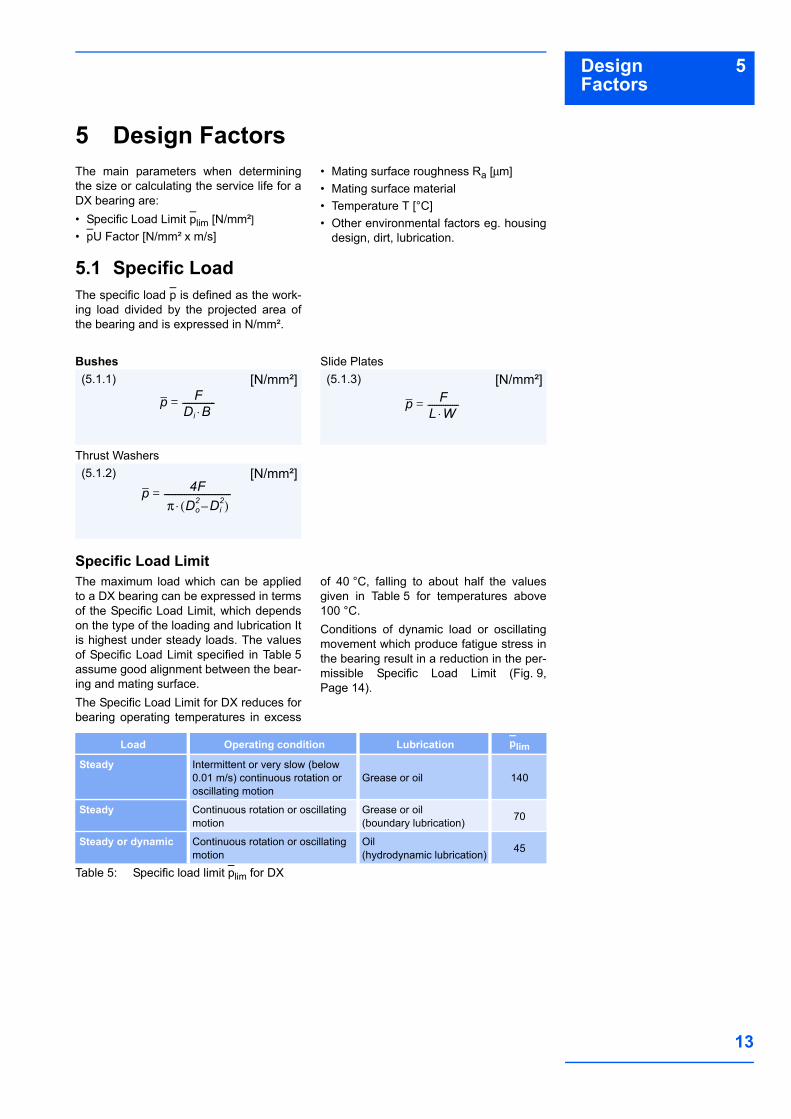
5.1 Specific LoadThe specific load p is defined as the work-ing load divided by the projected area ofthe bearing and is expressed in N/mm².
Bushes
Thrust Washers
Slide Plates
Specific Load LimitThe maximum load which can be appliedto a DX bearing can be expressed in termsof the Specific Load Limit, which dependson the type of the loading and lubrication Itis highest under steady loads. The valuesof Specific Load Limit specified in Table 5assume good alignment between the bear-ing and mating surface.The Specific Load Limit for DX reduces forbearing operating temperatures in excess
of 40 °C, falling to about half the valuesgiven in Table 5 for temperatures above100 °C.Conditions of dynamic load or oscillatingmovement which produce fatigue stress inthe bearing result in a reduction in the per-missible Specific Load Limit (Fig. 9,Page 14).
Table 5: Specific load limit plim for DX
(5.1.1) [N/mm²]
p FDi B⋅---------------=
(5.1.2) [N/mm²]p 4F
π Do2 Di
2–( )⋅------------------------------=
(5.1.3) [N/mm²]
p FL W⋅--------------=
Load Operating condition Lubrication plim
Steady Intermittent or very slow (below 0.01 m/s) continuous rotation or oscillating motion
Grease or oil 140
Steady Continuous rotation or oscillating motion
Grease or oil(boundary lubrication) 70
Steady or dynamic Continuous rotation or oscillating motion
Oil(hydrodynamic lubrication) 45
14
5 Design Factors
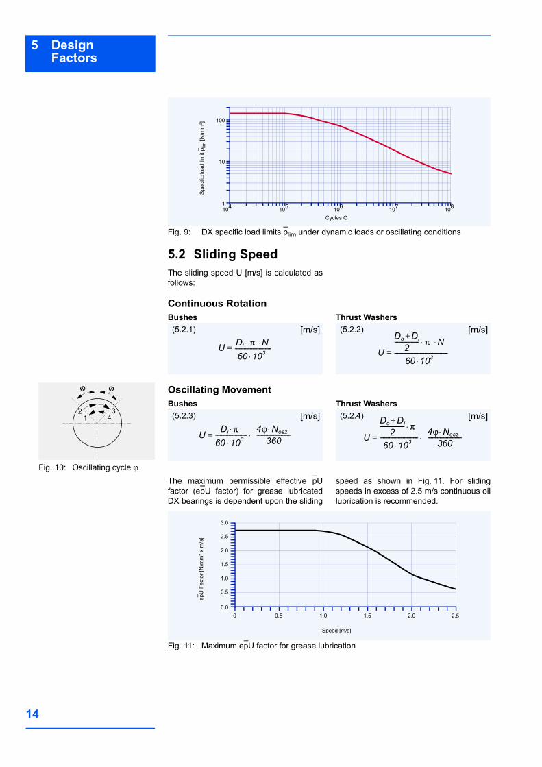
Fig. 9: DX specific load limits plim under dynamic loads or oscillating conditions
5.2 Sliding SpeedThe sliding speed U [m/s] is calculated asfollows:
Continuous RotationBushes Thrust Washers
Oscillating MovementBushes Thrust Washers
The maximum permissible effective pUfactor (epU factor) for grease lubricatedDX bearings is dependent upon the sliding
speed as shown in Fig. 11. For slidingspeeds in excess of 2.5 m/s continuous oillubrication is recommended.
Fig. 11: Maximum epU factor for grease lubrication
Spe
cific
load
lim
it p l
im [N
/mm
²]
Cycles Q1041
10
100
105 106 107 108
U Di π N⋅ ⋅60 103⋅------------------------=
(5.2.1) [m/s]
U
Do Di+2
---------------- π N⋅ ⋅
60 103⋅-----------------------------------=
(5.2.2) [m/s]
UDi π⋅60 103⋅--------------------- 4ϕ Nosz⋅
360----------------------⋅=
(5.2.3) [m/s]
U
Do Di+2
---------------- π⋅
60 103⋅------------------------- 4ϕ Nosz⋅
360----------------------⋅=
(5.2.4) [m/s]
Fig. 10: Oscillating cycle ϕ
ϕ ϕ
412 3
epU
Fac
tor [
N/m
m² x
m/s
]
Speed [m/s]
00.0
0.5
1.0
0.5 1.0 1.5 2.0 2.5
2.0
1.5
2.5
3.0
15
5Design Factors
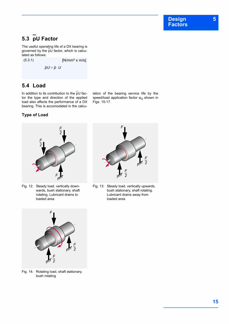
5.3 pU FactorThe useful operating life of a DX bearing isgoverned by the pU factor, which is calcu-lated as follows:
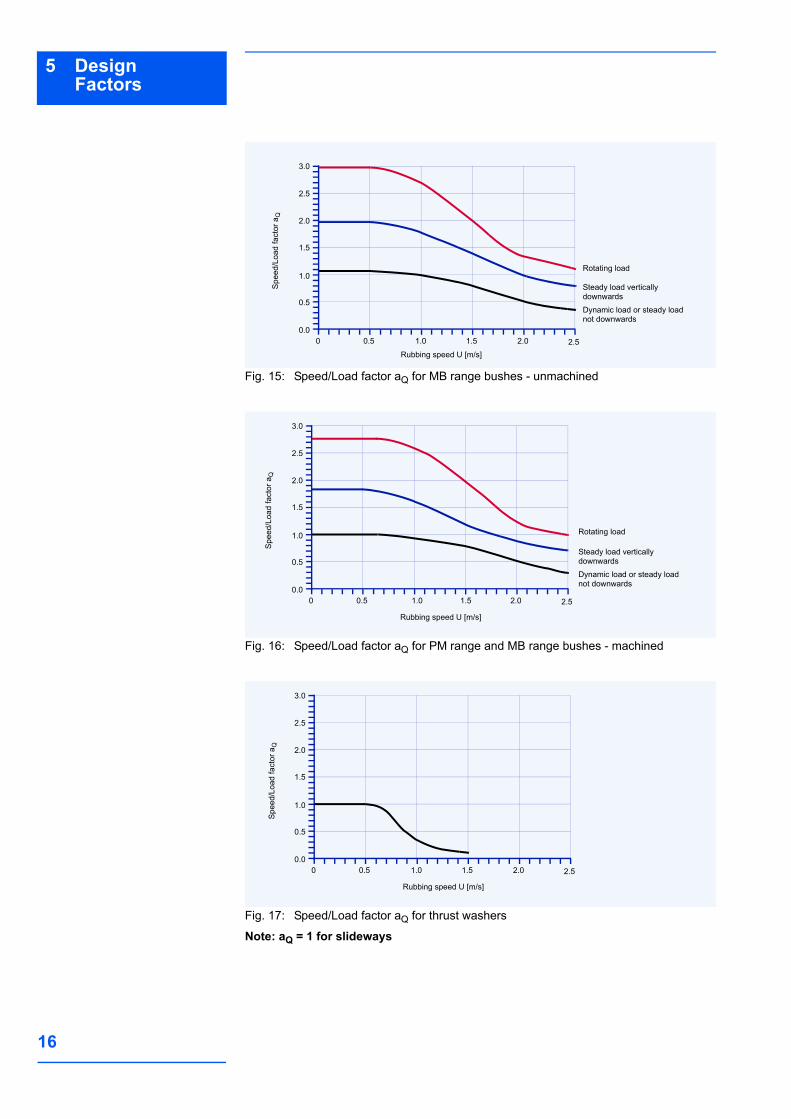
5.4 LoadIn addition to its contribution to the pU fac-tor the type and direction of the appliedload also affects the performance of a DXbearing. This is accomodated in the calcu-
lation of the bearing service life by thespeed/load application factor aQ shown inFigs. 15-17.
Type of Load
Fig. 12: Steady load, vertically down-wards, bush stationary, shaft rotating. Lubricant drains to loaded area
Fig. 13: Steady load, vertically upwards, bush stationary, shaft rotating. Lubricant drains away from loaded area
Fig. 14: Rotating load, shaft stationary, bush rotating
pU p U⋅=
(5.3.1) [N/mm² x m/s]
F2---
F2---
F
F2---
F2---
F
F2---
F2---
F
16
5 Design Factors
Fig. 15: Speed/Load factor aQ for MB range bushes - unmachined
Fig. 16: Speed/Load factor aQ for PM range and MB range bushes - machined
Fig. 17: Speed/Load factor aQ for thrust washers
Note: aQ = 1 for slideways
Rubbing speed U [m/s]
00.0
0.5
1.0
0.5 1.0 1.5 2.0 2.5
2.0
1.5
2.5
3.0
Rotating load
Steady load verticallydownwards
Dynamic load or steady loadnot downwards
Spee
d/Lo
ad fa
ctor
aQ
Rubbing speed U [m/s]
00.0
0.5
1.0
0.5 1.0 1.5 2.0 2.5
2.0
1.5
2.5
3.0
Rotating load
Steady load verticallydownwards
Dynamic load or steady loadnot downwards
Spe
ed/L
oad
fact
or a
Q
Rubbing speed U [m/s]
00.0
0.5
1.0
0.5 1.0 1.5 2.0 2.5
2.0
1.5
2.5
3.0
Spee
d/Lo
ad fa
ctor
aQ
17
5Design Factors
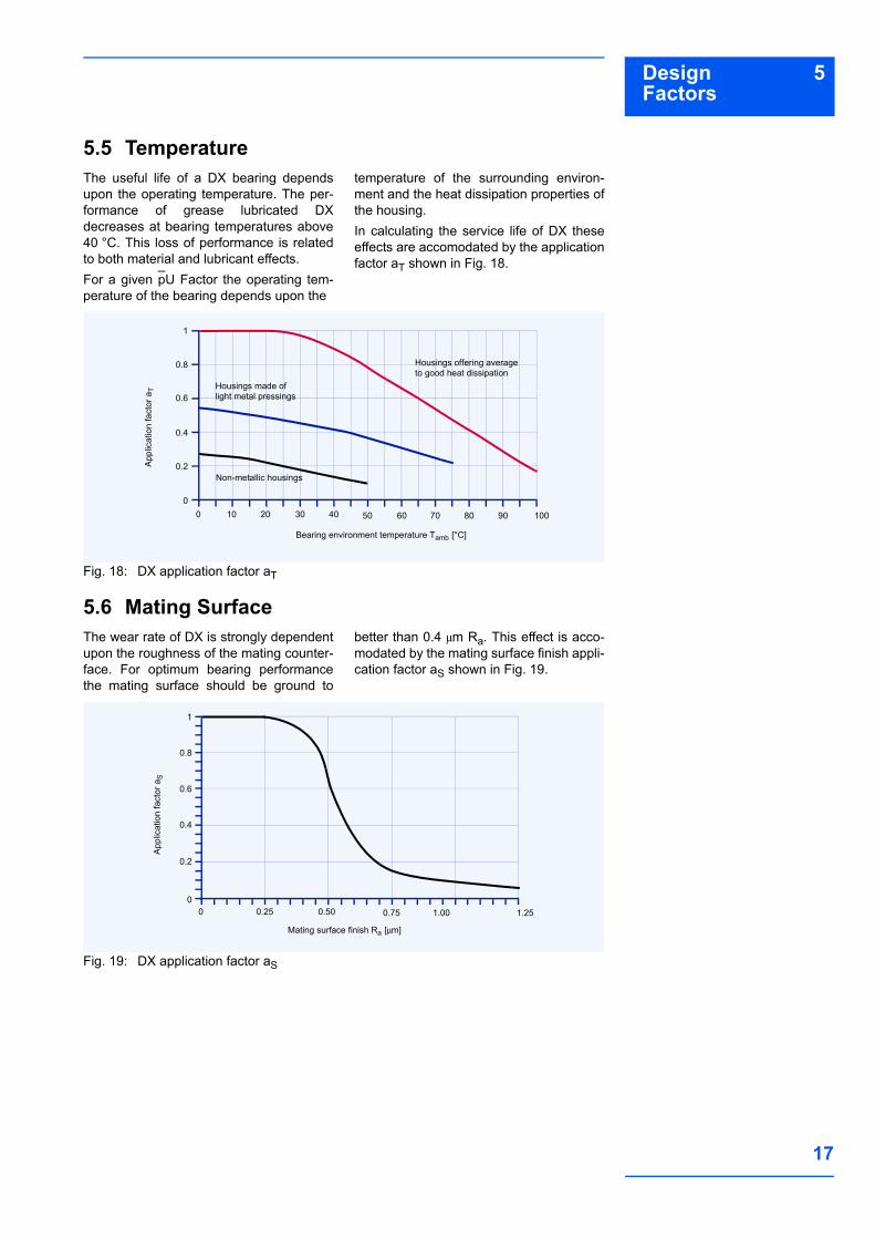
5.5 TemperatureThe useful life of a DX bearing dependsupon the operating temperature. The per-formance of grease lubricated DXdecreases at bearing temperatures above40 °C. This loss of performance is relatedto both material and lubricant effects.For a given pU Factor the operating tem-perature of the bearing depends upon the
temperature of the surrounding environ-ment and the heat dissipation properties ofthe housing.In calculating the service life of DX theseeffects are accomodated by the applicationfactor aT shown in Fig. 18.
Fig. 18: DX application factor aT
5.6 Mating SurfaceThe wear rate of DX is strongly dependentupon the roughness of the mating counter-face. For optimum bearing performancethe mating surface should be ground to
better than 0.4 µm Ra. This effect is acco-modated by the mating surface finish appli-cation factor aS shown in Fig. 19.
Fig. 19: DX application factor aS
Bearing environment temperature Tamb [°C]
00
0.2
0.4
10 20 30 40 50
0.8
0.6
1
Housings offering average to good heat dissipation
Housings made of light metal pressings
Non-metallic housings
60 70 80 90 100
App
licat
ion
fact
or a
T
Mating surface finish Ra [µm]
00
0.2
0.4
0.25 0.50
0.8
0.6
1
0.75 1.00 1.25
App
licat
ion
fact
or a
S
18
5 Design Factors
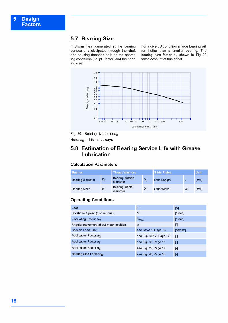
5.7 Bearing SizeFrictional heat generated at the bearingsurface and dissipated through the shaftand housing depends both on the operat-ing conditions (i.e. pU factor) and the bear-ing size.
For a give pU condition a large bearing willrun hotter than a smaller bearing. Thebearing size factor aB shown in Fig. 20takes account of this effect.
Fig. 20: Bearing size factor aB
Note: aB = 1 for slideways
5.8 Estimation of Bearing Service Life with Grease Lubrication
Calculation Parameters
Operating Conditions
Bea
ring
size
fact
ora B
Journal diameter DJ [mm]
80.1
0.2
0.3
9 10
0.40.5
0.80.60.70.91.0
1.5
3.0
2.0
15 20 30 40 50 70 100 150 200 500
Bushes Thrust Washers Slide Plates Unit
Bearing diameter DiBearing outsidediameter
Do Strip Length L [mm]
Bearing width B Bearing insidediameter
Di Strip Width W [mm]
Load F [N]
Rotational Speed (Continuous) N [1/min]
Oscillating Frequency Nosz [1/min]
Angular movement about mean position ϕ [°]
Specific Load Limit see Table 5, Page 13 [N/mm²]
Application Factor aQ see Fig. 15-17, Page 16 [-]
Application Factor aT see Fig. 18, Page 17 [-]
Application Factor aS see Fig. 19, Page 17 [-]
Bearing Size Factor aB see Fig. 20, Page 18 [-]

19
5Design Factors
Calculate p from the equations in 5.1 on Page 13. Calculate U from the equations in 5.2 on Page 14.Calculate pU from the equation in 5.3 on Page 15.
Calculate High Load Factor aE
Note:If aE >10000, or aE <0, the bearing is over-loaded.
Calculate Effective pU Factor epU
Note:Check that epU is less than the limit for thesliding speed U set in Fig. 11. If NOT,
increase the bearing length or use continu-ous lubrication.
Estimate Bearing LifeIf epU < 1.0 then If epU > 1.0 then
Estimate Re-greasing Interval
Oscillating Motion and Dynamic LoadsOscillating MotionCalculate number of cycles
Dynamic LoadsCalculate number of cycles
where R = Number of times bearing isregreased during total life required.Check that ZT (or CT) is less than the totalnumber of cycles Q given in Fig. 9 foractual bearing specific load p.If ZT (or CT) > Q then life will be limited byfatigue after Q cycles.
If ZT (or CT) < Q then life will be limited bywear after ZT cycles.If the estimated life or total cycles areinsufficient or the regreasing intervals aretoo frequent, increase the bearing lengthor diameter, or consider drip feed or con-tinuous oil lubrication, the quantity to beestablished by test.
aEplimplim p–----------------=
(5.8.1) [–]
plim see Table 5, Page 13
epU aE pU⋅aB
-------------------=
(5.8.2) [–]
LH3000epU------------- aQ aT aS⋅ ⋅ ⋅=
(5.8.3) [h]
LH3000epU( )2 ·4--------------------- aQ aT aS⋅ ⋅ ⋅=
(5.8.4) [h]
LRGLH2------=
(5.8.5) [h]
ZT LRG Nosz 60 R 2+( )⋅⋅ ⋅=
(5.8.6) [–]CT LRG C 60 R 2+( )⋅⋅ ⋅=
(5.8.7) [–]
20
5 Design Factors
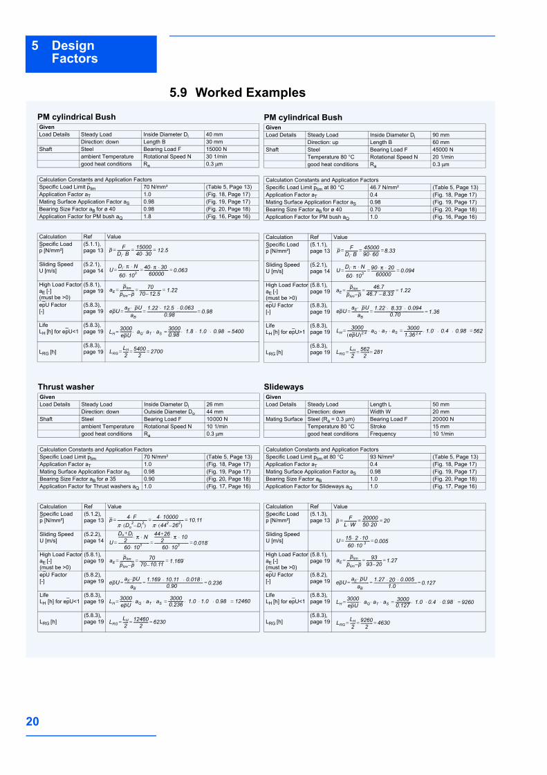
5.9 Worked Examples
PM cylindrical BushGivenLoad Details Steady Load Inside Diameter Di 40 mm
Direction: down Length B 30 mmShaft Steel Bearing Load F 15000 N
ambient Temperature Rotational Speed N 30 1/mingood heat conditions Ra 0.3 µm
Calculation Constants and Application FactorsSpecific Load Limit plim 70 N/mm² (Table 5, Page 13)Application Factor aT 1.0 (Fig. 18, Page 17)Mating Surface Application Factor aS 0.98 (Fig. 19, Page 17)Bearing Size Factor aB for ø 40 0.98 (Fig. 20, Page 18)Application Factor for PM bush aQ 1.8 (Fig. 16, Page 16)
Calculation Ref ValueSpecific Load p [N/mm²]
(5.1.1), page 13
Sliding Speed U [m/s]
(5.2.1), page 14
High Load FactoraE [-] (must be >0)
(5.8.1), page 19
epU Factor[-]
(5.8.3), page 19
LifeLH [h] for epU<1
(5.8.3), page 19
LRG [h](5.8.3), page 19
p FDi B⋅-------------- 15000
40 30⋅------------------ 12 5,= = = 12.5
U Di π N⋅ ⋅
60 103⋅----------------------- 40 π 30⋅ ⋅
60000-------------------------- 0 063,= = =0.063
aEplimplim p–--------------- 70
70 12 5,–------------------------ 1 22,= = = 1.22
12.5
epU aE pU⋅aB
------------------- 1 22, 12 5, 0 063,⋅ ⋅0 98,
------------------------------------------------------ 0 98,== =12.5 0.0631.22 0.980.98
LH3000epU------------- aQ aT aS⋅ ⋅ ⋅ 3000
0 98,------------- 1⋅ 8, 1 0, 0 98,⋅ ⋅ 5400= = =0.98 54001.8 0.981.01.8
LRGLH2------ 5400
2------------- 2700= = =
PM cylindrical BushGivenLoad Details Steady Load Inside Diameter Di 90 mm
Direction: up Length B 60 mmShaft Steel Bearing Load F 45000 N
Temperature 80 °C Rotational Speed N 20 1/mingood heat conditions Ra 0.3 µm
Calculation Constants and Application FactorsSpecific Load Limit plim at 80 °C 46.7 N/mm² (Table 5, Page 13)Application Factor aT 0.4 (Fig. 18, Page 17)Mating Surface Application Factor aS 0.98 (Fig. 19, Page 17)Bearing Size Factor aB for ø 40 0.70 (Fig. 20, Page 18)Application Factor for PM bush aQ 1.0 (Fig. 16, Page 16)
Calculation Ref ValueSpecific Load p [N/mm²]
(5.1.1), page 13
Sliding Speed U [m/s]
(5.2.1), page 14
High Load FactoraE [-](must be >0)
(5.8.1), page 19
epU Factor[-]
(5.8.3), page 19
LifeLH [h] for epU>1
(5.8.3), page 19
LRG [h](5.8.3), page 19
p FDi B⋅-------------- 45000
90 60⋅------------------ 8= = =8.33
U Di π N⋅ ⋅
60 103⋅----------------------- 90 π 20⋅ ⋅
60000-------------------------- 0 094,= = =0.094
aEplimplim p–--------------- 46 7,
46 7, 8 33,–------------------------------- 1 22,= = = 1.2246.746.7 8.33
epU aE pU⋅aB
------------------- 1 22, 8 33, 0 094,⋅ ⋅0 70,
------------------------------------------------------ 1 36,== =1.22 0.0948.33
0.70 1.36
LH3000epU( )2 4,---------------------- aQ aT aS⋅ ⋅ ⋅ 3000
1 36, 2 4,-------------------- 1⋅ 0, 0 4, 0 98,⋅ ⋅ 562= = =5620.980.42.4 2.41.36
1.0
LRGLH2------ 562
2----------== = 281
Thrust washerGivenLoad Details Steady Load Inside Diameter Di 26 mm
Direction: down Outside Diameter Do 44 mmShaft Steel Bearing Load F 10000 N
ambient Temperature Rotational Speed N 10 1/mingood heat conditions Ra 0.3 µm
Calculation Constants and Application FactorsSpecific Load Limit plim 70 N/mm² (Table 5, Page 13)Application Factor aT 1.0 (Fig. 18, Page 17)Mating Surface Application Factor aS 0.98 (Fig. 19, Page 17)Bearing Size Factor aB for ø 35 0.90 (Fig. 20, Page 18)Application Factor for Thrust washers aQ 1.0 (Fig. 17, Page 16)
Calculation Ref ValueSpecific Load p [N/mm²]
(5.1.2), page 13
Sliding Speed U [m/s]
(5.2.2), page 14
High Load FactoraE [-](must be >0)
(5.8.1), page 19
epU Factor[-]
(5.8.2), page 19
LifeLH [h] for epU<1
(5.8.3), page 19
LRG [h](5.8.3), page 19
p 4 F⋅π Do
2 Di2–( )⋅
-------------------------------- 4 10000⋅π 442 262–( )⋅---------------------------------- 10 11,= = =10.11
UDo Di+2
---------------- π N⋅ ⋅
60 103⋅----------------------------------
44 26+2
----------------- π 10⋅ ⋅
60 103⋅------------------------------------- 0 018,= = =0.018
aEplimplim p–--------------- 70
70 10 11,–--------------------------- 1 169,= = =10.11 1.169
epU aE pU⋅aB
------------------- 1 169, 10 11, 0 018,⋅ ⋅0 90,
------------------------------------------------------------- 0 236,== = 0.901.169 10.11 0.018 0.236
LH3000epU------------- aQ aT aS⋅ ⋅ ⋅ 3000
0 236,----------------- 1⋅ 0, 1 0, 0 98,⋅ ⋅ 12460= = = 124601.0 0.981.00.236
LRGLH2------ 12460
2---------------- 6230= = =
SlidewaysGivenLoad Details Steady Load Length L 50 mm
Direction: down Width W 20 mmMating Surface Steel (Ra = 0.3 µm) Bearing Load F 20000 N
Temperature 80 °C Stroke 15 mmgood heat conditions Frequency 10 1/min
Calculation Constants and Application FactorsSpecific Load Limit plim at 80 °C 93 N/mm² (Table 5, Page 13)Application Factor aT 0.4 (Fig. 18, Page 17)Mating Surface Application Factor aS 0.98 (Fig. 19, Page 17)Bearing Size Factor aB 1.0 (Fig. 20, Page 18)Application Factor for Slideways aQ 1.0 (Fig. 17, Page 16)
Calculation Ref ValueSpecific Load p [N/mm²]
(5.1.3), page 13
Sliding Speed U [m/s]
High Load FactoraE [-](must be >0)
(5.8.1), page 19
epU Factor[-]
(5.8.2), page 19
LifeLH [h] for epU<1
(5.8.3), page 19
LRG [h](5.8.3), page 19
p FL W⋅-------------- 20000
50 20⋅------------------ 20= = =
U 15 2 10⋅ ⋅60 10 3⋅--------------------------- 0 005,= =0.005
aEplimplim p–--------------- 93
93 20–----------------- 1 27,= = =1.27
epU aE pU⋅aB
------------------- 1 27, 20 0 005,⋅ ⋅1 0,
----------------------------------------------- 0 127,== = 1.271.0
0.005 0.127
LH3000epU------------- aQ aT aS⋅ ⋅ ⋅ 3000
0 127,----------------- 1⋅ 0, 0 4, 0 98,⋅ ⋅ 9260= = =0.127 1.0 0.4 0.98
LRGLH2------ 9260
2------------- 4630= = =
21
6Data Sheet
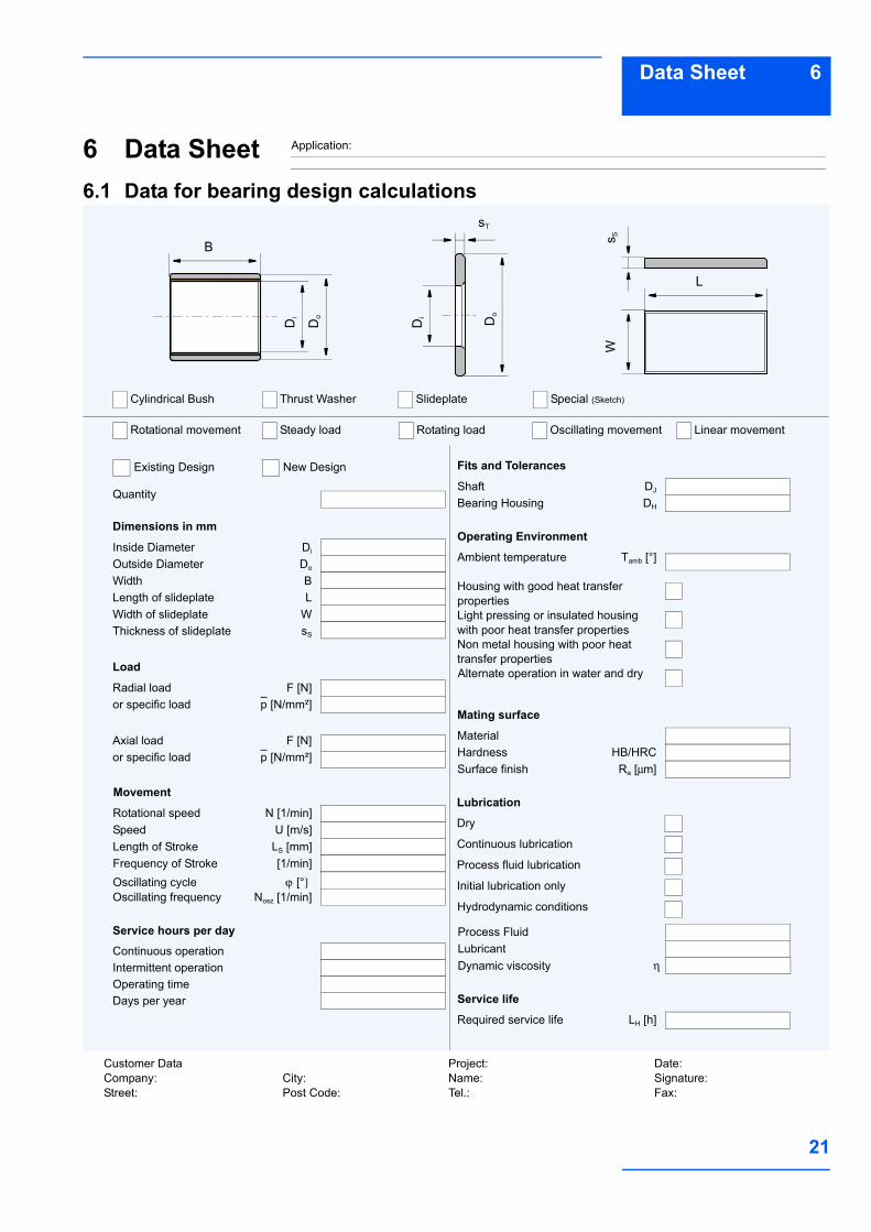
6 Data Sheet6.1 Data for bearing design calculations
Application:
Quantity
Dimensions in mm
Inside Diameter Di
Width B
Outside Diameter Do
Length of slideplate LWidth of slideplate WThickness of slideplate sS
Radial load F [N]or specific load p [N/mm²]
Axial load F [N]or specific load p [N/mm²]
Oscillating frequency Nosz [1/min]
Rotational speed N [1/min]Speed U [m/s]Length of Stroke LS [mm]Frequency of Stroke [1/min]Oscillating cycle ϕ [°]
Continuous operation
Load
Service hours per day
Days per yearOperating timeIntermittent operation
Movement
Shaft DJ
Bearing Housing DH
Fits and Tolerances
Ambient temperature Tamb [°]
Operating Environment
Non metal housing with poor heat transfer properties
Light pressing or insulated housing with poor heat transfer properties
Housing with good heat transfer properties
Material
Mating surface
Surface finish Ra [µm]Hardness HB/HRC
Process FluidLubricant
Alternate operation in water and dry
Dry
Lubrication
Process fluid lubrication
Continuous lubrication
Initial lubrication only
Hydrodynamic conditions
Dynamic viscosity η
Required service life LH [h]
Service life
Rotational movement Steady load Rotating load Oscillating movement
Cylindrical Bush Thrust Washer Slideplate
Existing Design New Design
Special (Sketch)
Linear movement
B
Di
Do
Di Do
Ws S
sT
L
Customer DataCompany:Street:
Project:Name:Tel.:
Date:Signature:Fax:
City:Post Code:
22
7 Bearing Assembly
7 Bearing Assembly7.1 Dimensions and TolerancesFor optimum performance it is essentialthat the correct running clearance is usedand that both the diameter of the shaft andthe bore of the housing are finished to thelimits given in the tables.If the bearing housing is unusually flexiblethe bush will not close in by the calculated
amount and the running clearance will bemore than the optimum. In these circum-stances the housing should be boredslightly undersize or the journal diameterincreased, the correct size being deter-mined by experiment.
7.2 Tolerances for minimum clearance
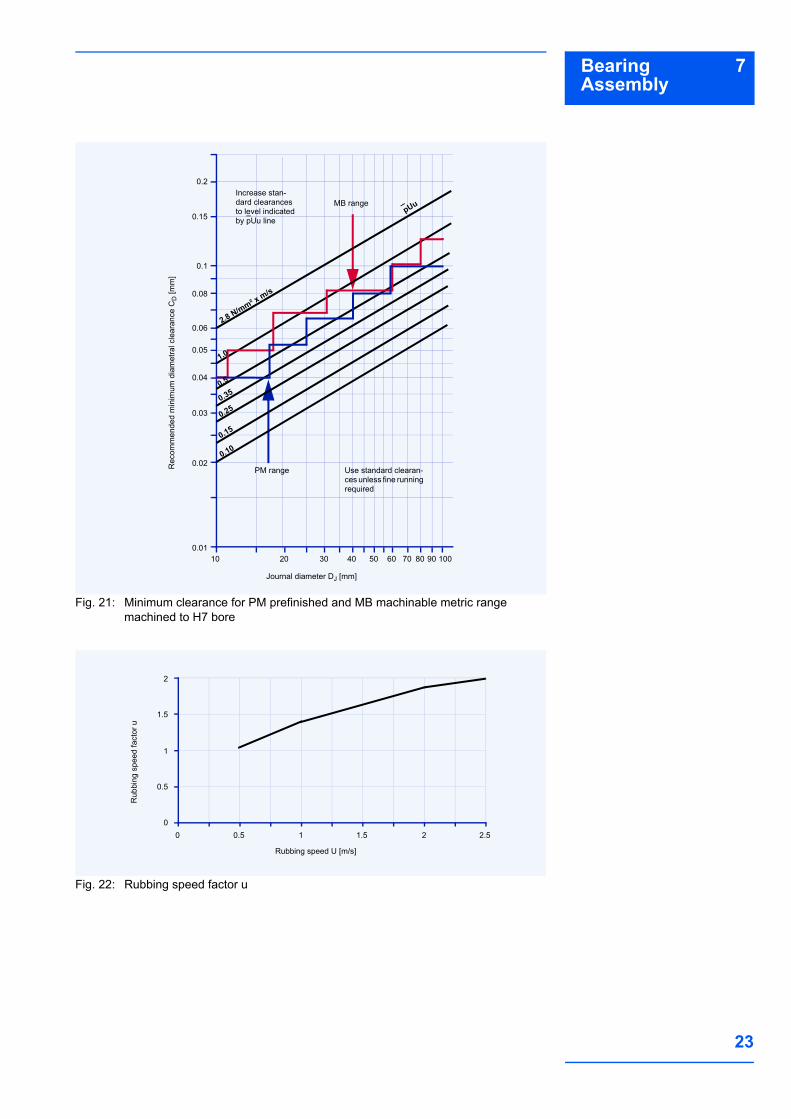
Grease lubricationThe minimum clearance required for satis-factory performance of DX depends uponthe pU factor, the sliding speed and theenvironmental temperature, any one orcombination of which may reduce thediametral clearance in operation due toinward thermal expansion of the DX poly-mer lining. It is therefore necessary tocompensate for this.Fig. 21 shows the minimum diametralclearance plotted stepped against journaldiameter at an ambient 20 °C. Where thestepped lines show a change of clearancefor a given journal diameter, the lowervalue is used. The superimposed straight lines indicatethe minimum permissible diametral clear-
ance for various values of pUu (Fig. 21),where pU is calculated as in 5.3 onPage 15, and u is a sliding speed factor forspeeds in excess of 0.5 m/s given inFig. 22.If the clearance indicated for a pUu factorlies below the stepped lines the recom-mended standard shaft may be used. Ifabove, the shaft size must be reduced toobtain the clearance indicated on the verti-cal axis of the relevant figure.Under slow speed and high load conditionsit may be possible to achieve satisfactoryperformance with diametral clearancesless than those indicated. But adequateprototype testing is recommended in suchcases.
23
7Bearing Assembly
Fig. 21: Minimum clearance for PM prefinished and MB machinable metric range machined to H7 bore
Fig. 22: Rubbing speed factor u
Rec
omm
ende
d m
inim
um d
iam
etra
l cle
aran
ce C
D [m
m]
Journal diameter DJ [mm]
100.01
0.02
0.03
20 30 40 50 60 80 10070 90
0.04
0.05
0.06
0.08
0.1
0.15
0.2
PM range Use standard clearan-ces unless fine running required
Increase stan-dard clearances to level indicated by pUu line
MB range
2.8 N/mm² x m/s
1.0
0.5
0.35
0.25
0.15
0.10
pUu
Rub
bing
spe
ed fa
ctor
u
Rubbing speed U [m/s]
0.5
1
2
0 0.5 1
1.5
01.5 2 2.5

24
7 Bearing Assembly
Fluid LubricationThe minimum clearance required for jour-nal bearings operating under hydrody-namic or mixed film conditions for a rangeof shaft rotational speeds and diameters is
shown in Fig. 23 It is recommended thatthe bearing performance under minimumclearance conditions be confirmed by test-ing if possible.
Fig. 23: DX minimum clearances - bush diameters Di 10-50 mm
Allowance for Thermal ExpansionFor operation in high temperature environ-ments the clearance should be increasedby the amounts indicated by Fig. 24 to
compensate for the inward thermal expan-sion of the bearing lining.
Fig. 24: Recommended increase in diametral clearanceIf the housing is non-ferrous then the boreshould be reduced by the amounts given inTable 6, in order to give an increased inter-
ference fit to the bush, with a similar reduc-tion in the journal diameter additional tothat indicated by Fig. 24.
Dia
met
ral c
lear
ance
CD
[mm
]
Speed N [rev/min]
00.01
0.02
100
0.03
0.05
0.06
0.04
1000
Detail design required for rubbing speeds above 3 m/s
50 45 40 35 3025
20
15
18
12
10
Incr
ease
in m
inim
um d
iam
etra
l cle
aran
ce [m
m]
Environmental temperature Tamb [° C]
0.01
0.02
0 40 60 800
20 100 120 140 160
0.03
0.04
0.05
25
7Bearing Assembly
Table 6: Allowance for high temperature
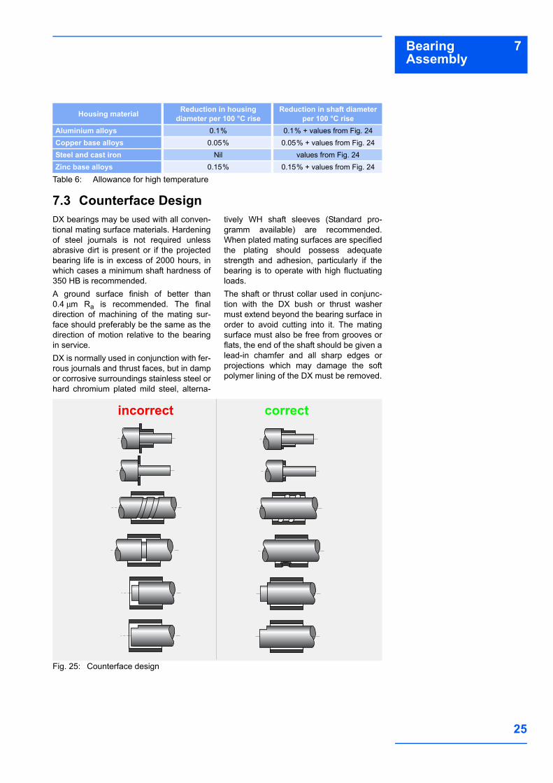
7.3 Counterface DesignDX bearings may be used with all conven-tional mating surface materials. Hardeningof steel journals is not required unlessabrasive dirt is present or if the projectedbearing life is in excess of 2000 hours, inwhich cases a minimum shaft hardness of350 HB is recommended.A ground surface finish of better than0.4 µm Ra is recommended. The finaldirection of machining of the mating sur-face should preferably be the same as thedirection of motion relative to the bearingin service.DX is normally used in conjunction with fer-rous journals and thrust faces, but in dampor corrosive surroundings stainless steel orhard chromium plated mild steel, alterna-
tively WH shaft sleeves (Standard pro-gramm available) are recommended.When plated mating surfaces are specifiedthe plating should possess adequatestrength and adhesion, particularly if thebearing is to operate with high fluctuatingloads.The shaft or thrust collar used in conjunc-tion with the DX bush or thrust washermust extend beyond the bearing surface inorder to avoid cutting into it. The matingsurface must also be free from grooves orflats, the end of the shaft should be given alead-in chamfer and all sharp edges orprojections which may damage the softpolymer lining of the DX must be removed.
Fig. 25: Counterface design
Housing material Reduction in housing diameter per 100 °C rise
Reduction in shaft diameter per 100 °C rise
Aluminium alloys 0.1% 0.1% + values from Fig. 24Copper base alloys 0.05% 0.05% + values from Fig. 24Steel and cast iron Nil values from Fig. 24Zinc base alloys 0.15% 0.15% + values from Fig. 24
incorrect correct
26
7 Bearing Assembly
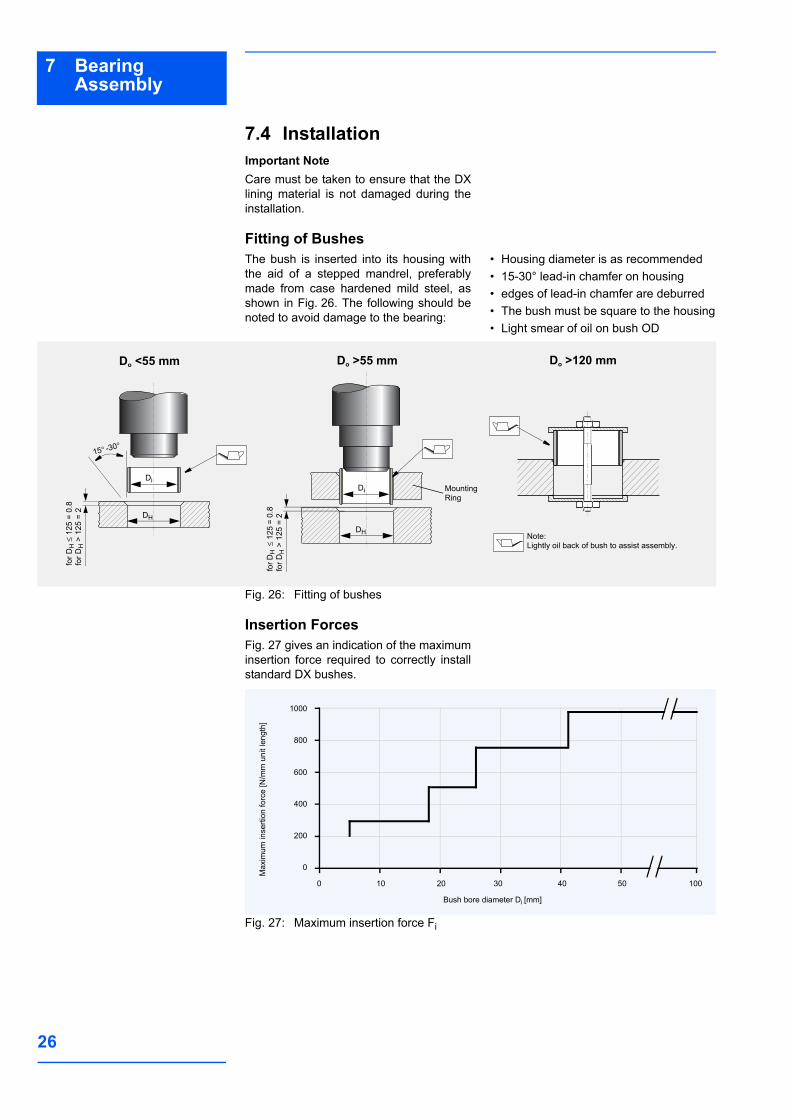
7.4 InstallationImportant NoteCare must be taken to ensure that the DXlining material is not damaged during theinstallation.
Fitting of BushesThe bush is inserted into its housing withthe aid of a stepped mandrel, preferablymade from case hardened mild steel, asshown in Fig. 26. The following should benoted to avoid damage to the bearing:
• Housing diameter is as recommended• 15-30° lead-in chamfer on housing• edges of lead-in chamfer are deburred• The bush must be square to the housing• Light smear of oil on bush OD
Fig. 26: Fitting of bushes
Insertion ForcesFig. 27 gives an indication of the maximuminsertion force required to correctly installstandard DX bushes.
Fig. 27: Maximum insertion force Fi
Do <55 mm Do >55 mm Do >120 mm
15° -30°
Mounting Ring
Note:Lightly oil back of bush to assist assembly.
for D
H ≤
125
= 0.
8fo
r DH
> 1
25 =
2
for D
H ≤
125
= 0.
8fo
r DH
> 1
25 =
2
DiDi
DH
DH
Max
imum
inse
rtion
forc
e [N
/mm
uni
t len
gth]
Bush bore diameter Di [mm]
200
400
1000
0 30 40 50
800
0
20 100
600
10

27
7Bearing Assembly
AlignmentAccurate alignment is an important consid-eration for all bearing assemblies. With DXbearings misalignment over the length of a
bush (or pair of bushes), or over the diam-eter of a thrust washer should not exceed0.020 mm as illustrated in Fig. 28.
Fig. 28: Alignment
SealingWhile DX can tolerate the ingress of somecontaminant materials into the bearingwithout loss of performance, where there isthe possibility of highly abrasive material
entering the bearing, a suitable sealingarrangement, as illustrated in Fig. 29should be provided.
Fig. 29: Recommended sealing arrangements
Axial LocationWhere axial location is necessary, it is gen-erally advisable to fit DX thrust washers inconjunction with DX bushes, even whenthe axial loads are low. Experience has
shown that fretting debris from unsatisfac-tory locating surfaces can enter an adja-cent DX bush and adversely affect thebearing life and performance.
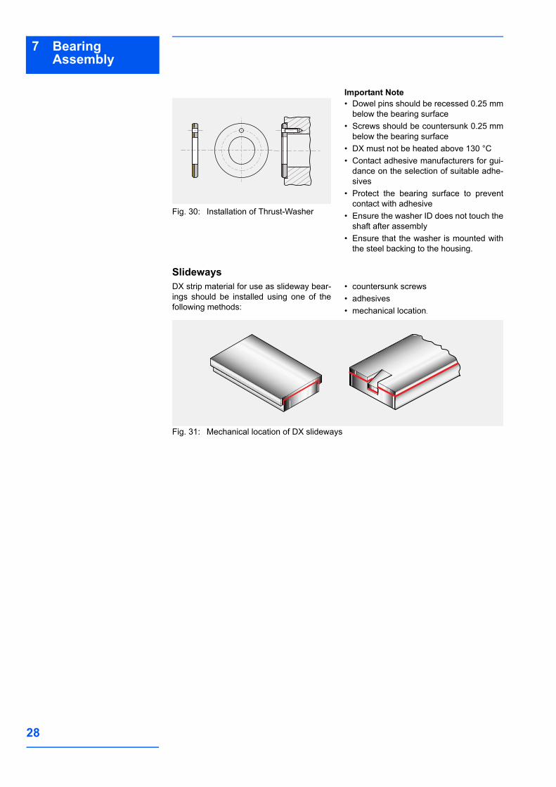
Fitting of Thrust WashersDX thrust washers should be located onthe outside diameter in a recess as shownin Fig. 30. The inside diameter must beclear of the shaft in order to prevent con-tact with the steel backing of the DX mate-rial. The recess diameter should be 0.125mm larger than the washer diameter andthe depth as given in the product tables.
If there is no recess for the thrust washerone of the following methods of fixing maybe used:• two dowel pins• two screws• adhesive.
28
7 Bearing Assembly
Fig. 30: Installation of Thrust-Washer
Important Note• Dowel pins should be recessed 0.25 mm
below the bearing surface• Screws should be countersunk 0.25 mm
below the bearing surface• DX must not be heated above 130 °C• Contact adhesive manufacturers for gui-
dance on the selection of suitable adhe-sives
• Protect the bearing surface to preventcontact with adhesive
• Ensure the washer ID does not touch theshaft after assembly
• Ensure that the washer is mounted withthe steel backing to the housing.
SlidewaysDX strip material for use as slideway bear-ings should be installed using one of thefollowing methods:
• countersunk screws• adhesives• mechanical location.
Fig. 31: Mechanical location of DX slideways
29
8Machining
8 Machining8.1 Machining PracticeThe acetal copolymer lining of DX hasgood machining characteristics and can betreated as a free cutting brass in mostrespects. The indents in the bearing sur-face may lead to the formation of burrs orwhiskers due to the resilience of the liningmaterial, but this can be avoided by usingmachining methods which remove the lin-ing as a ribbon, rather than a narrowthread.
When machining DX it is recommendedthat not more than 0.125 mm is removedfrom the lining thickness in order to ensurethat the lubricant capacity of the indentsremaining after machining is not signifi-cantly reduced.Boring, reaming and broaching are all suit-able machining methods for use with DX.The recommended tool material is highspeed steel or tungsten carbide.
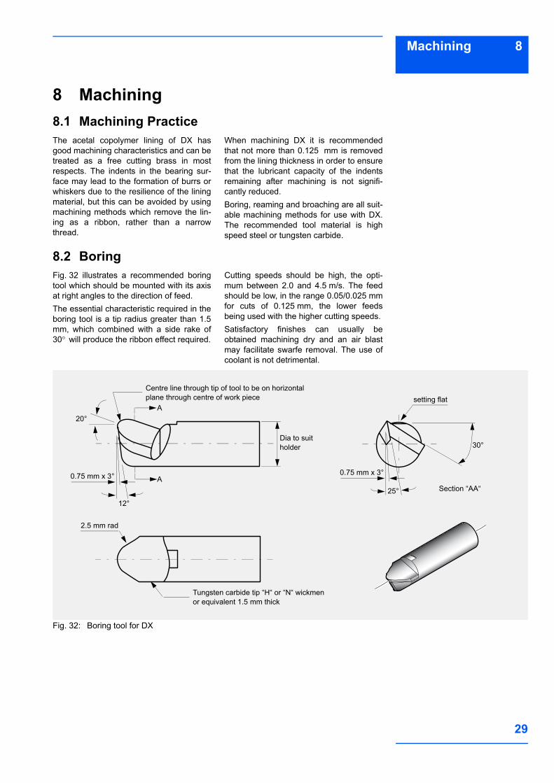
8.2 BoringFig. 32 illustrates a recommended boringtool which should be mounted with its axisat right angles to the direction of feed.The essential characteristic required in theboring tool is a tip radius greater than 1.5mm, which combined with a side rake of30° will produce the ribbon effect required.
Cutting speeds should be high, the opti-mum between 2.0 and 4.5 m/s. The feedshould be low, in the range 0.05/0.025 mmfor cuts of 0.125 mm, the lower feedsbeing used with the higher cutting speeds.Satisfactory finishes can usually beobtained machining dry and an air blastmay facilitate swarfe removal. The use ofcoolant is not detrimental.
Fig. 32: Boring tool for DX
12°
setting flatCentre line through tip of tool to be on horizontal plane through centre of work piece
Section “AA“
20°A
30°Dia to suit holder
0.75 mm x 3°
2.5 mm rad
A
Tungsten carbide tip “H“ or “N“ wickmen or equivalent 1.5 mm thick
25°
0.75 mm x 3°
30
8 Machining
8.3 ReamingMB-DX-bushes can be reamed satisfacto-rily by hand with a straight-fluted expand-ing reamer. For best results the reamershould be sharp, the cut 0.025-0.050 mm
and the feed slow. Where hand reaming isnot desired machining speeds of about0.05 m/s are recommended with the cutsand feeds as for boring.
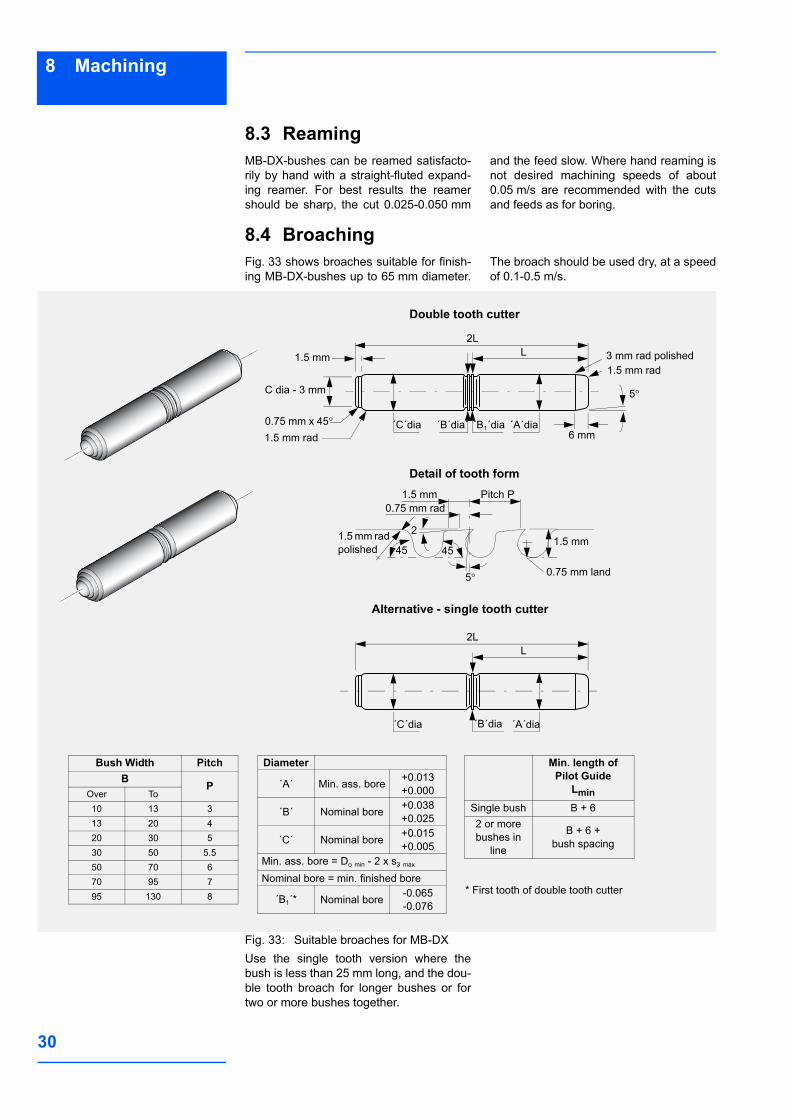
8.4 BroachingFig. 33 shows broaches suitable for finish-ing MB-DX-bushes up to 65 mm diameter.
The broach should be used dry, at a speedof 0.1-0.5 m/s.
Fig. 33: Suitable broaches for MB-DXUse the single tooth version where thebush is less than 25 mm long, and the dou-ble tooth broach for longer bushes or fortwo or more bushes together.
Bush Width PitchB P
Over To10 13 313 20 420 30 530 50 5.550 70 670 95 795 130 8
Diameter
´A´ Min. ass. bore +0.013+0.000
´B´ Nominal bore +0.038+0.025
´C´ Nominal bore +0.015+0.005
Min. ass. bore = Do min - 2 x s3 max
Nominal bore = min. finished bore
´B1´* Nominal bore -0.065-0.076
Min. length of Pilot Guide
LminSingle bush B + 62 or morebushes in
line
B + 6 +bush spacing
5°
6 mm
3 mm rad polished1.5 mm rad
1.5 mm
2LL
´A´dia´B1´dia´B´dia´´C´dia
C dia - 3 mm
0.75 mm x 45°1.5 mm rad
2LL
´B´dia´C´dia ´A´dia
Pitch P0.75 mm rad
1.5 mm
5°
45 45
2
0.75 mm land
1.5 mm1.5 mm rad polished
Alternative - single tooth cutter
Detail of tooth form
Double tooth cutter
* First tooth of double tooth cutter
31
8Machining
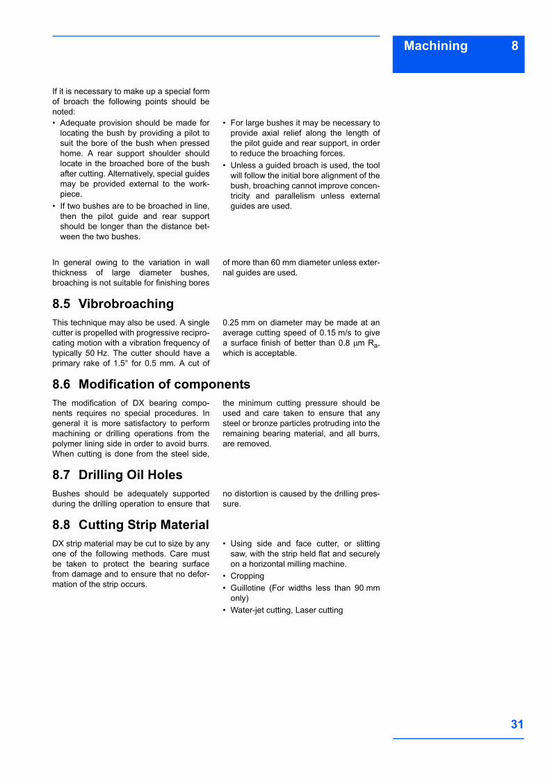
If it is necessary to make up a special formof broach the following points should benoted:• Adequate provision should be made for
locating the bush by providing a pilot tosuit the bore of the bush when pressedhome. A rear support shoulder shouldlocate in the broached bore of the bushafter cutting. Alternatively, special guidesmay be provided external to the work-piece.
• If two bushes are to be broached in line,then the pilot guide and rear supportshould be longer than the distance bet-ween the two bushes.
• For large bushes it may be necessary toprovide axial relief along the length ofthe pilot guide and rear support, in orderto reduce the broaching forces.
• Unless a guided broach is used, the toolwill follow the initial bore alignment of thebush, broaching cannot improve concen-tricity and parallelism unless externalguides are used.
In general owing to the variation in wallthickness of large diameter bushes,broaching is not suitable for finishing bores
of more than 60 mm diameter unless exter-nal guides are used.
8.5 VibrobroachingThis technique may also be used. A singlecutter is propelled with progressive recipro-cating motion with a vibration frequency oftypically 50 Hz. The cutter should have aprimary rake of 1.5° for 0.5 mm. A cut of
0.25 mm on diameter may be made at anaverage cutting speed of 0.15 m/s to givea surface finish of better than 0.8 µm Ra,which is acceptable.
8.6 Modification of componentsThe modification of DX bearing compo-nents requires no special procedures. Ingeneral it is more satisfactory to performmachining or drilling operations from thepolymer lining side in order to avoid burrs.When cutting is done from the steel side,
the minimum cutting pressure should beused and care taken to ensure that anysteel or bronze particles protruding into theremaining bearing material, and all burrs,are removed.
8.7 Drilling Oil HolesBushes should be adequately supportedduring the drilling operation to ensure that
no distortion is caused by the drilling pres-sure.
8.8 Cutting Strip MaterialDX strip material may be cut to size by anyone of the following methods. Care mustbe taken to protect the bearing surfacefrom damage and to ensure that no defor-mation of the strip occurs.
• Using side and face cutter, or slittingsaw, with the strip held flat and securelyon a horizontal milling machine.
• Cropping• Guillotine (For widths less than 90 mm
only)• Water-jet cutting, Laser cutting
32
9 Electroplating
9 ElectroplatingDX ComponentsTo provide corrosion protection the mildsteel backing of DX may be electroplatedwith most of the conventional electroplat-ing metals including the following:• zinc ISO 2081-2• cadmium ISO 2081-2• nickel ISO 1456-8• hard chromium ISO 1456-8.
For the harder materials if the specifiedplating thickness exceeds approximately5 µm then the housing diameter should beincreased by twice the plating thickness inorder to maintain the correct assembledbearing bore size.Where electrolytic attack is possible testsshould be conducted to ensure that all thematerials in the bearing environment aremutually compatible.
Mating SurfacesDX can be used against hard chromeplated materials and care should be takento ensure that the recommended shaft
sizes and surface finish are achieved afterthe plating process.

33
10Standard Products
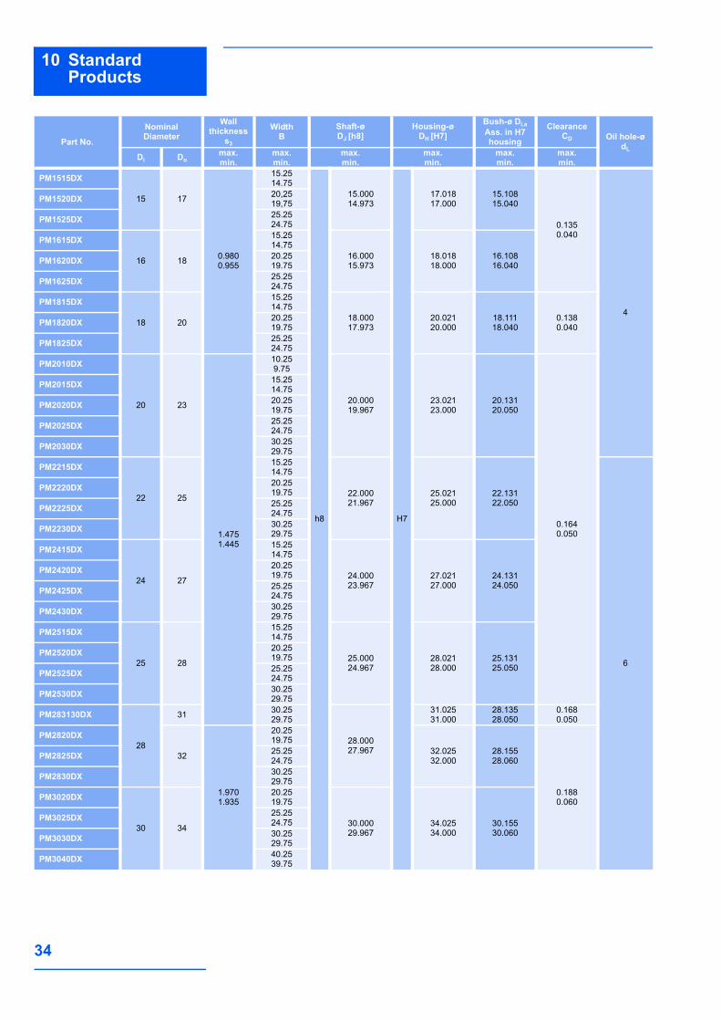
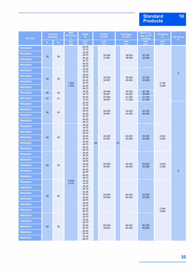
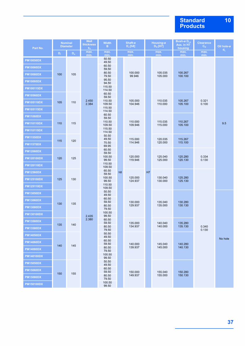
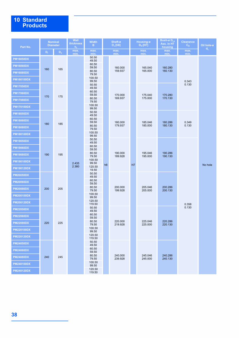
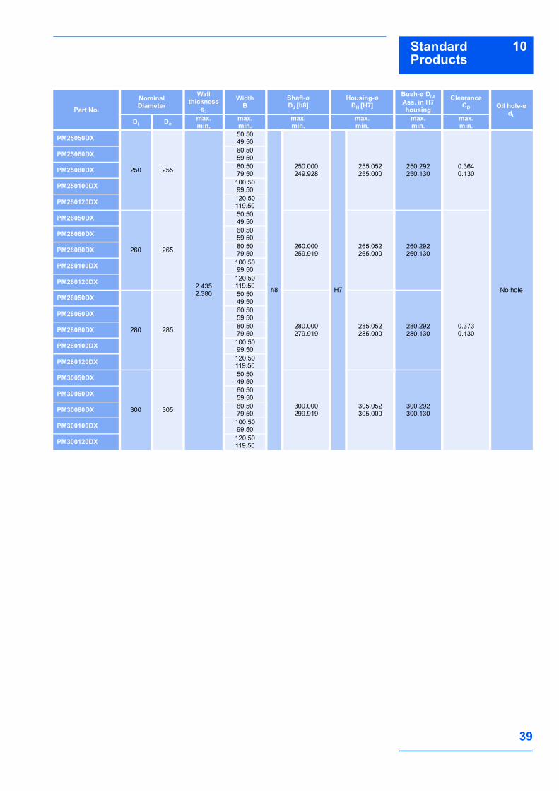
10 Standard Products10.1PM-DX cylindrical bushes
All dimensions in mm
dL0.3
min
.
20˚ ± 8˚Co
Ci
B
s 3D
i(D
i,a)
Do
120
Dimensions and tolerances follow ISO 3547 and GSP-Specifications
Detail Z
Split
Part No.
NominalDiameter
Wallthickness
s3
WidthB
Shaft-øDJ [h8]
Housing-øDH [H7]
Bush-ø Di,a Ass. in H7 housing
ClearanceCD Oil hole-ø
dLDi Do
max.min.
max.min.
max.min.
max.min.
max.min.
max.min.
PM0808DX
8 10
0.9800.955
8.257.75
h8
8.0007.978
H7
10.01510.000
8.1058.040
0.1270.040 No holePM0810DX 10.25
9.75
PM0812DX 12.2511.75
PM1010DX
10 12
10.259.75
10.0009.978
12.01812.000
10.10810.040
0.1300.040
3
PM1012DX 12.2511.75
4PM1015DX 15.2514.75
PM1020DX 20.2519.75
PM1210DX
12 14
10.259.75
12.00011.973
14.01814.000
12.10812.040
0.1350.040
3
PM1212DX 12.2511.75
4
PM1215DX 15.2514.75
PM1220DX 20.2519.75
PM1225DX 25.2524.75
PM1415DX
14 16
15.2514.75
14.00013.973
16.01816.000
14.10814.040PM1420DX 20.25
19.75
PM1425DX 25.2524.75
PM1510DX15 17
10.259.75 15.000
14.97317.01817.000
15.10815.040
3
PM1512DX 12.2511.75 4
Outside Co and Inside Ci chamfers
a = Chamfer Co machined or rolled at the opinion of the manufacturer
b = Ci can be a radius or a chamfer in accordance with ISO 13715
Wall thickness s3
Co (a)Ci (b)
machined rolled0.75 0.5 ± 0.3 0.5 ± 0.3 -0.1 to -0.4
1 0.6 ± 0.4 0.6 ± 0.4 -0.1 to -0.51.5 0.6 ± 0.4 0.6 ± 0.4 -0.1 to -0.7
Wall thickness s3
Co (a)Ci (b)
machined rolled2 1.2 ± 0.4 1.0 ± 0.4 -0.1 to -0.7
2.5 1.8 ± 0.6 1.2 ± 0.4 -0.2 to -1.0
34
10 Standard Products
PM1515DX
15 17
0.9800.955
15.2514.75
h8
15.00014.973
H7
17.01817.000
15.10815.040
0.1350.040
4
PM1520DX 20,2519,75
PM1525DX 25.2524.75
PM1615DX
16 18
15.2514.75
16.00015.973
18.01818.000
16.10816.040PM1620DX 20.25
19.75
PM1625DX 25.2524.75
PM1815DX
18 20
15.2514.75
18.00017.973
20.02120.000
18.11118.040
0.1380.040PM1820DX 20.25
19.75
PM1825DX 25.2524.75
PM2010DX
20 23
1.4751.445
10.259.75
20.00019.967
23.02123.000
20.13120.050
0.1640.050
PM2015DX 15.2514.75
PM2020DX 20.2519.75
PM2025DX 25.2524.75
PM2030DX 30.2529.75
PM2215DX
22 25
15.2514.75
22.00021.967
25.02125.000
22.13122.050
6
PM2220DX 20.2519.75
PM2225DX 25.2524.75
PM2230DX 30.2529.75
PM2415DX
24 27
15.2514.75
24.00023.967
27.02127.000
24.13124.050
PM2420DX 20.2519.75
PM2425DX 25.2524.75
PM2430DX 30.2529.75
PM2515DX
25 28
15.2514.75
25.00024.967
28.02128.000
25.13125.050
PM2520DX 20.2519.75
PM2525DX 25.2524.75
PM2530DX 30.2529.75
PM283130DX
28
31 30.2529.75
28.00027.967
31.02531.000
28.13528.050
0.1680.050
PM2820DX
32
1.9701.935
20.2519.75
32.02532.000
28.15528.060
0.1880.060
PM2825DX 25.2524.75
PM2830DX 30.2529.75
PM3020DX
30 34
20.2519.75
30.00029.967
34.02534.000
30.15530.060
PM3025DX 25.2524.75
PM3030DX 30.2529.75
PM3040DX 40.2539.75
Part No.
NominalDiameter
Wallthickness
s3
WidthB
Shaft-øDJ [h8]
Housing-øDH [H7]
Bush-ø Di,a Ass. in H7 housing
ClearanceCD Oil hole-ø
dLDi Do
max.min.
max.min.
max.min.
max.min.
max.min.
max.min.
35
10Standard Products
PM3220DX
32 36
1.9701.935
20.2519.75
h8
32.00031.961
H7
36.02536.000
32.15532.060
0.1940.060
6
PM3230DX 30.2529.75
PM3235DX 35.2534.75
PM3240DX 40.2539.75
PM3520DX
35 39
20.2519.75
35.00034.961
39.02539.000
35.15535.060
PM3530DX 30.2529.75
PM3535DX 35.2534.75
PM3550DX 50.2549.75
PM3635DX 36 40 35.2534.75
36.00035.961
40.02540.000
36.15536.060
PM3720DX 37 41 20.2519.75
37.00036.961
41.02541.000
37.15537.060
PM4020DX
40 44
20.2519.75
40.00039.961
44.02544.000
40.15540.060
8
PM4030DX 30.2529.75
PM4040DX 40.2539.75
PM4050DX 50.2549.75
PM4520DX
45 50
2.4602.415
20.2519.75
45.00044.961
50.02550.000
45.19545.080
0.2340.080
PM4530DX 30.2529.75
PM4540DX 40.2539.75
PM4545DX 45.2544.75
PM4550DX 50.2549.75
PM5030DX
50 55
30.2529.75
50.00049.961
55.03055.000
50.20050.080
0.2390.080
PM5040DX 40.2539.75
PM5045DX 45,2544,75
PM5050DX 50.2549.75
PM5060DX 60.2559.75
PM5520DX
55 60
20.2519.75
55.00054.954
60.03060.000
55.20055.080
0.2460.080
PM5525DX 25.2524.75
PM5530DX 30.2529.75
PM5540DX 40.2539.75
PM5550DX 50.2549.75
PM5560DX 60.2559.75
PM6030DX
60 65
30.2529.75
60.00059.954
65.03065.000
60.20060.080
PM6040DX 40.2539.75
PM6050DX 50.2549.75
PM6060DX 60.2559.75
PM6070DX 70.2569.75
Part No.
NominalDiameter
Wallthickness
s3
WidthB
Shaft-øDJ [h8]
Housing-øDH [H7]
Bush-ø Di,a Ass. in H7 housing
ClearanceCD Oil hole-ø
dLDi Do
max.min.
max.min.
max.min.
max.min.
max.min.
max.min.

36
10 Standard Products
PM6540DX
65 70
2.4502.384
40.2539.75
h8
65.00064.954
H7
70.03070.000
65.26265.100
0.3080.100
8
PM6550DX 50.2549.75
PM6560DX 60.2559.75
PM6570DX 70.2569.75
PM7040DX
70 75
40.2539.75
70.00069.954
75.03075.000
70.26270.100
PM7050DX 50.2549.75
PM7060DX 60,2559,75
PM7065DX 65.2564.75
PM7070DX 70.2569.75
PM7080DX 80.2579.75
PM7540DX
75 80
40.2539.75
75.00074.954
80.03080.000
75.26275.100
9.5
PM7560DX 60.2559.75
PM7580DX 80.2579.75
PM8040DX
80 85
40.5039.50
80.00079.954
85.03585.000
80.26780.100
0.3130.100
PM8050DX 50,5049,50
PM8060DX 60.5059.50
PM8080DX 80.5079.50
PM80100DX 100.5099.50
PM8530DX
85 90
30.5029.50
85.00084.946
90.03590.000
85.26785.100
0.3210.100
PM8540DX 40.5039.50
PM8560DX 60.5059.50
PM8580DX 80.5079.50
PM85100DX 100.5099.50
PM9040DX
90 95
40.5039.50
90.00089.946
95.03595.000
90.26790.100
PM9060DX 60.5059.50
PM9080DX 80.5079.50
PM9090DX 90.5089.50
PM90100DX 100.5099.50
PM9560DX95 100
60.5059.50 95.000
94.946100.035100.000
95.26795.100PM95100DX 100.50
99.50
Part No.
NominalDiameter
Wallthickness
s3
WidthB
Shaft-øDJ [h8]
Housing-øDH [H7]
Bush-ø Di,a Ass. in H7 housing
ClearanceCD Oil hole-ø
dLDi Do
max.min.
max.min.
max.min.
max.min.
max.min.
max.min.
37
10Standard Products
PM10050DX
100 105
2.4502.384
50.5049.50
h8
100.00099.946
H7
105.035105.000
100.267100.100
0.3210.100
9.5
PM10060DX 60.5059.50
PM10080DX 80.5079.50
PM10095DX 95.5094.50
PM100115DX 115.50114.50
PM10560DX
105 110
60.5059.50
105.000104.946
110.035110.000
105.267105.100PM105110DX 110.50
109.50
PM105115DX 115.50114.50
PM11060DX
110 115
60.5059.50
110.000109.946
115.035115.000
110.267105.100PM110110DX 110.50
109.50
PM110115DX 115.50114.50
PM11550DX115 120
50.5049.50 115.000
114.946120.035120.000
115.267115.100PM11570DX 70.50
69.95
PM12060DX
120 125
2.4352.380
60.5059.50
120.000119.946
125.040125.000
120.280120.130
0.3340.130PM120100DX 100.50
99.50
PM120110DX 110.50109.50
PM12560DX
125 130
60.5059.50
125.000124.937
130.040130.000
125.280125.130
0.3400.130
PM125100DX 100.5099.50
PM125110DX 110.50109.50
PM13050DX
130 135
50.5049.50
130.000129.937
135.040135.000
130.280130.130
No hole
PM13060DX 60.5059.50
PM13080DX 80.5079.50
PM130100DX 100.5099.50
PM13560DX135 140
60.5059.50 135.000
134.937140.040140.000
135.280135.130PM13580DX 80.50
79.50
PM14050DX
140 145
50.5049.50
140.000139.937
145.040145.000
140.280140.130
PM14060DX 60.5059.50
PM14080DX 80.5079.50
PM140100DX 100.5099.50
PM15050DX
150 155
50.5049.50
150.000149.937
155.040155.000
150.280150.130
PM15060DX 60.5059.50
PM15080DX 80.5079.50
PM150100DX 100.5099.50
Part No.
NominalDiameter
Wallthickness
s3
WidthB
Shaft-øDJ [h8]
Housing-øDH [H7]
Bush-ø Di,a Ass. in H7 housing
ClearanceCD Oil hole-ø
dLDi Do
max.min.
max.min.
max.min.
max.min.
max.min.
max.min.
38
10 Standard Products
PM16050DX
160 165
2.4352.380
50.5049.50
h8
160.000159.937
H7
165.040165.000
160.280160.130
0.3430.130
No hole
PM16060DX 60.5059.50
PM16080DX 80.5079.50
PM160100DX 100.5099.50
PM17050DX
170 175
50.5049.50
170.000169.937
175.040175.000
170.280170.130
PM17060DX 60.5059.50
PM17080DX 80.5079.50
PM170100DX 100.5099.50
PM18050DX
180 185
50.5049.50
180.000179.937
185.046185.000
180.286180.130
0.3490.130
PM18060DX 60.5059.50
PM18080DX 80.5079.50
PM180100DX 100.5099.50
PM19050DX
190 195
50.5049.50
190.000189.928
195.046195.000
190.286190.130
0.3580.130
PM19060DX 60.5059.50
PM19080DX 80.5079.50
PM190100DX 100.5099.50
PM190120DX 120.5019.50
PM20050DX
200 205
50.5049.50
200.000199.928
205.046205.000
200.286200.130
PM20060DX 60.5059.50
PM20080DX 80.5079.50
PM200100DX 100.5099.50
PM200120DX 120.50119.50
PM22050DX
220 225
50.5049.50
220.000219.928
225.046225.000
220.286220.130
PM22060DX 60.5059.50
PM22080DX 80.5079.50
PM220100DX 100.5099.50
PM220120DX 120.50119.50
PM24050DX
240 245
50.5049.50
240.000239.928
245.046245.000
240.286240.130
PM24060DX 60.5059.50
PM24080DX 80.5079.50
PM240100DX 100.5099.50
PM240120DX 120.50119.50
Part No.
NominalDiameter
Wallthickness
s3
WidthB
Shaft-øDJ [h8]
Housing-øDH [H7]
Bush-ø Di,a Ass. in H7 housing
ClearanceCD Oil hole-ø
dLDi Do
max.min.
max.min.
max.min.
max.min.
max.min.
max.min.
39
10Standard Products
PM25050DX
250 255
2.4352.380
50.5049.50
h8
250.000249.928
H7
255.052255.000
250.292250.130
0.3640.130
No hole
PM25060DX 60.5059.50
PM25080DX 80.5079.50
PM250100DX 100.5099.50
PM250120DX 120.50119.50
PM26050DX
260 265
50.5049.50
260.000259.919
265.052265.000
260.292260.130
0.3730.130
PM26060DX 60.5059.50
PM26080DX 80.5079.50
PM260100DX 100.5099.50
PM260120DX 120.50119.50
PM28050DX
280 285
50.5049.50
280.000279.919
285.052285.000
280.292280.130
PM28060DX 60.5059.50
PM28080DX 80.5079.50
PM280100DX 100.5099.50
PM280120DX 120.50119.50
PM30050DX
300 305
50.5049.50
300.000299.919
305.052305.000
300.292300.130
PM30060DX 60.5059.50
PM30080DX 80.5079.50
PM300100DX 100.5099.50
PM300120DX 120.50119.50
Part No.
NominalDiameter
Wallthickness
s3
WidthB
Shaft-øDJ [h8]
Housing-øDH [H7]
Bush-ø Di,a Ass. in H7 housing
ClearanceCD Oil hole-ø
dLDi Do
max.min.
max.min.
max.min.
max.min.
max.min.
max.min.
40
10 Standard Products
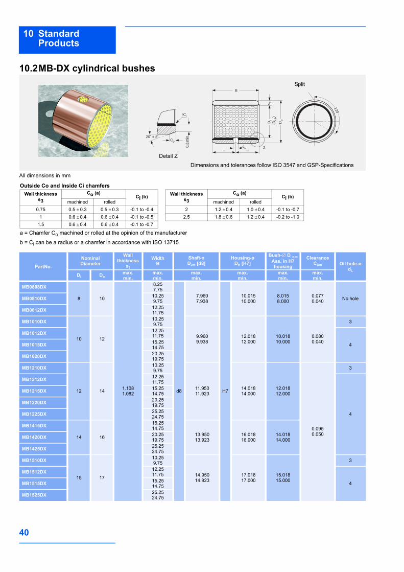
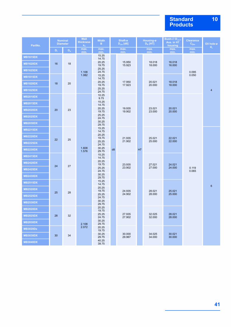
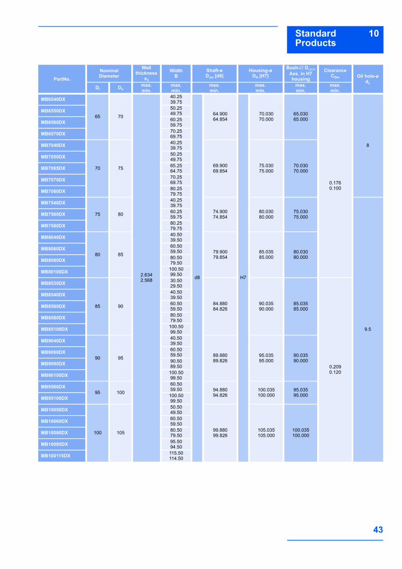
10.2MB-DX cylindrical bushes
All dimensions in mm
dL0.3
min
.
20˚ ± 8˚Co
Ci
B
s 3D
i(D
i,a)
Do
120
Z
Dimensions and tolerances follow ISO 3547 and GSP-SpecificationsDetail Z
Split
PartNo.
NominalDiameter
Wallthickness
s3
WidthB
Shaft-øDJm [d8]
Housing-øDH [H7]
Bush-∅ Di,a,mAss. in H7 housing
ClearanceCDm Oil hole-ø
dLDi Do
max.min.
max.min.
max.min.
max.min.
max.min.
max.min.
MB0808DX
8 10
1.1081.082
8.257.75
d8
7.9607.938
H7
10.01510.000
8.0158.000
0.0770.040 No holeMB0810DX 10.25
9.75
MB0812DX 12.2511.75
MB1010DX
10 12
10.259.75
9.9609.938
12.01812.000
10.01810.000
0.0800.040
3
MB1012DX 12.2511.75
4MB1015DX 15.2514.75
MB1020DX 20.2519.75
MB1210DX
12 14
10.259.75
11.95011.923
14.01814.000
12.01812.000
0.0950.050
3
MB1212DX 12.2511.75
4
MB1215DX 15.2514.75
MB1220DX 20.2519.75
MB1225DX 25.2524.75
MB1415DX
14 16
15.2514.75
13.95013.923
16.01816.000
14.01814.000MB1420DX 20.25
19.75
MB1425DX 25.2524.75
MB1510DX
15 17
10.259.75
14.95014.923
17.01817.000
15.01815.000
3
MB1512DX 12.2511.75
4MB1515DX 15.2514.75
MB1525DX 25.2524.75
Outside Co and Inside Ci chamfers
a = Chamfer Co machined or rolled at the opinion of the manufacturer
b = Ci can be a radius or a chamfer in accordance with ISO 13715
Wall thickness s3
Co (a)Ci (b)
machined rolled0.75 0.5 ± 0.3 0.5 ± 0.3 -0.1 to -0.4
1 0.6 ± 0.4 0.6 ± 0.4 -0.1 to -0.51.5 0.6 ± 0.4 0.6 ± 0.4 -0.1 to -0.7
Wall thickness s3
Co (a)Ci (b)
machined rolled2 1.2 ± 0.4 1.0 ± 0.4 -0.1 to -0.7
2.5 1.8 ± 0.6 1.2 ± 0.4 -0.2 to -1.0
41
10Standard Products
MB1615DX
16 18
1.1081.082
15.2514.75
d8
15.95015.923
H7
18.01818.000
16.01816.000
0.0950.050
4
MB1620DX 20.2519.75
MB1625DX 25.2524.75
MB1815DX
18 20
15.2514.75
17.95017.923
20.02120.000
18.01818.000MB1820DX 20.25
19.75
MB1825DX 25.2524.75
MB2010DX
20 23
1.6081.576
10.259.75
19.93519.902
23.02123.000
20.02120.000
0.1190.065
MB2015DX 15.2514.75
MB2020DX 20.2519.75
MB2025DX 25.2524.75
MB2030DX 30.2529.75
MB2215DX
22 25
15.2514.75
21.93521.902
25.02125.000
22.02122.000
6
MB2220DX 20.2519.75
MB2225DX 25.2524.75
MB2230DX 30.2529.75
MB2415DX
24 27
15.2514.75
23.93523.902
27.02127.000
24.02124.000
MB2420DX 20.2519.75
MB2425DX 25.2524.75
MB2430DX 30.2529.75
MB2515DX
25 28
15.2514.75
24.93524.902
28.02128.000
25.02125.000
MB2520DX 20.2519.75
MB2525DX 25.2524.75
MB2530DX 30.2529.75
MB2820DX
28 32
2.1082.072
20.2519.75
27.93527.902
32.02532.000
28.02128.000MB2825DX 25.25
24.75
MB2830DX 30.2529.75
MB3020Dx
30 34
20.2519.75
30.00029.967
34.02534.000
30.02130.000MB3030DX 30.25
29.75
MB3040DX 40.2539.75
PartNo.
NominalDiameter
Wallthickness
s3
WidthB
Shaft-øDJm [d8]
Housing-øDH [H7]
Bush-∅ Di,a,mAss. in H7 housing
ClearanceCDm Oil hole-ø
dLDi Do
max.min.
max.min.
max.min.
max.min.
max.min.
max.min.

42
10 Standard Products
MB3220DX
32 36
2.1082.072
20.2519.75
d8
31.92031.881
H7
36.02536.000
32.02532.000
0.1440.080
6
MB3230DX 30.2529.75
MB3235DX 35.2534.75
MB3240DX 40.2539.75
MB3520DX
35 39
20.2519.75
34.92034.881
39.02539.000
35.02535.000MB3530DX 30.25
29.75
MB3550DX 50.2549.75
MB3720DX 37 41 20.2519.75
36.92036.881
41.02541.000
37.02537.000
MB4020DX
40 44
20.2519.75
39.92039.881
44.02544.000
40.02540.000
8
MB4030DX 30.2529.75
MB4040DX 40.2539.75
MB4050DX 50.2549.75
MB4520DX
45 50
2.6342.588
20.2519.75
44.92044.881
50.02550.000
45.02545.000
MB4530DX 30.2529.75
MB4540DX 40.2539.75
MB4545DX 45.2544.75
MB4550DX 50.2549.75
MB5040DX50 55
40.2539.75 49.920
49.88155.03055.000
50.02550.000MB5060DX 60.25
59.75
MB5520DX
55 60
20.2519.75
54.90054.854
60.03060.000
55.03055.000
0.1760.100
MB5525DX 25.2524.75
MB5530DX 30.2529.75
MB5540DX 40.2539.75
MB5550DX 50.2549.75
MB5560DX 60.2559.75
MB6030DX
60 65
30.2529.75
59.90059.854
65.03065.000
60.03060.000
MB6040DX 40.2539.75
MB6060DX 60.2559.75
MB6070DX 70.2569.75
PartNo.
NominalDiameter
Wallthickness
s3
WidthB
Shaft-øDJm [d8]
Housing-øDH [H7]
Bush-∅ Di,a,mAss. in H7 housing
ClearanceCDm Oil hole-ø
dLDi Do
max.min.
max.min.
max.min.
max.min.
max.min.
max.min.
43
10Standard Products
MB6540DX
65 70
2.6342.568
40.2539.75
d8
64.90064.854
H7
70.03070.000
65.03065.000
0.1760.100
8
MB6550DX 50.2549.75
MB6560DX 60.2559.75
MB6570DX 70.2569.75
MB7040DX
70 75
40.2539.75
69.90069.854
75.03075.000
70.03070.000
MB7050DX 50.2549.75
MB7065DX 65.2564.75
MB7070DX 70.2569.75
MB7080DX 80.2579.75
MB7540DX
75 80
40.2539.75
74.90074.854
80.03080.000
75.03075.000
9.5
MB7560DX 60.2559.75
MB7580DX 80.2579.75
MB8040DX
80 85
40.5039.50
79.90079.854
85.03585.000
80.03080.000
MB8060DX 60.5059.50
MB8080DX 80.5079.50
MB80100DX 100.5099.50
MB8530DX
85 90
30.5029.50
84.88084.826
90.03590.000
85.03585.000
0.2090.120
MB8540DX 40.5039.50
MB8560DX 60.5059.50
MB8580DX 80.5079.50
MB85100DX 100.5099.50
MB9040DX
90 95
40.5039.50
89.88089.826
95.03595.000
90.03590.000
MB9060DX 60.5059.50
MB9090DX 90.5089.50
MB90100DX 100.5099.50
MB9560DX95 100
60.5059.50 94.880
94.826100.035100.000
95.03595.000MB95100DX 100.50
99.50
MB10050DX
100 105
50.5049.50
99.88099.826
105.035105.000
100.035100.000
MB10060DX 60.5059.50
MB10080DX 80.5079.50
MB10095DX 95.5094.50
MB100115DX 115.50114.50
PartNo.
NominalDiameter
Wallthickness
s3
WidthB
Shaft-øDJm [d8]
Housing-øDH [H7]
Bush-∅ Di,a,mAss. in H7 housing
ClearanceCDm Oil hole-ø
dLDi Do
max.min.
max.min.
max.min.
max.min.
max.min.
max.min.
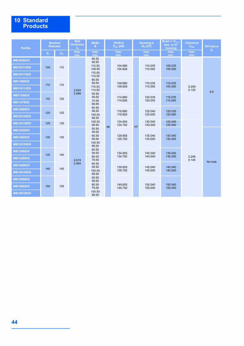
44
10 Standard Products
MB10560DX
105 110
2.6342.568
60.5059.50
d8
104.880104.826
H7
110.035110.000
105.035105.000
0.2090.120 9.5
MB105110DX 110.50109.50
MB105115DX 115.50114.50
MB11060DX110 115
60.5059.50 109.880
109.826115.035115.000
110.035105.000MB110115DX 115.50
114.50
MB11550DX115 120
50.5049.50 114.880
114.826120.035120.000
115.035115.000MB11570DX 70.50
69.95
MB12060DX120 125
60.5059.50 119.880
119.826125.040125.000
120.035120.000MB120100DX 100.50
99.50
MB125100DX 125 130 100.5099.50
124.855124.792
130.040130.000
125.040125.000
0.2480.145
MB13050DX
130 135
2.6192.564
50.5049.50
129.855129.792
135.040135.000
130.040130.000
No hole
MB13060DX 60.5059.50
MB130100DX 100.5099.50
MB13560DX135 140
60.5059.50 134.855
134.792140.040140.000
135.040135.000MB13580DX 80.50
79.50
MB14060DX140 145
60.5059.50 139.855
139.792145.040145.000
140.040140.000MB140100DX 100.50
99.50
MB15060DX
150 155
60.5059.50
149.855149.792
155.040155.000
150.040150.000MB15080DX 80.50
79.50
MB150100DX 100.5099.50
PartNo.
NominalDiameter
Wallthickness
s3
WidthB
Shaft-øDJm [d8]
Housing-øDH [H7]
Bush-∅ Di,a,mAss. in H7 housing
ClearanceCDm Oil hole-ø
dLDi Do
max.min.
max.min.
max.min.
max.min.
max.min.
max.min.
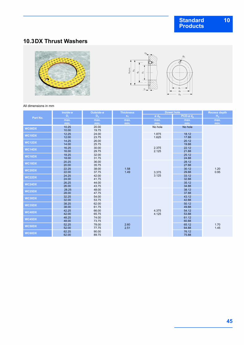
45
10Standard Products
10.3DX Thrust Washers
All dimensions in mm
dP
Di
Do
sT
Ha
Do
d p
dD
Hd
[D10
]
DJ
Part No.
Inside-øDi
Outside-øDo
ThicknesssT
Dowel hole Recess depthHaø dD PCD-ø dp
max.min.
max.min.
max.min.
max.min.
max.min.
max.min.
WC08DX 10.2510.00
20.0019.75
1.581.49
No hole No hole
1.200.95
WC10DX 12.2512.00
24.0023.75
1.8751.625
18.1217.88
WC12DX 14.2514.00
26.0025.75
2.3752.125
20.1219.88
WC14DX 16.2516.00
30.0029.75
22.1221.88
WC16DX 18.2518.00
32.0031.75
25.1224.88
WC18DX 20.2520.00
36.0035.75
3.3753.125
28.1227.88
WC20DX 22.2522.00
38.0037.75
30.1229.88
WC22DX 24.2524.00
42.0041.75
33.1232.88
WC24DX 26.2526.00
44.0043.75
35.1234.88
WC25DX 28.2528.00
48.0047.75
4.3754.125
38.1237.88
WC30DX 32.2532.00
54.0053.75
43.1242.88
WC35DX 38.2538.00
62.0061.75
50.1249.88
WC40DX 42.2542.00
66.0065.75
54.1253.88
WC45DX 48.2548.00
74.0073.75
2.602.51
61.1260.88
1.701.45WC50DX 52.25
52.0078.0077.75
65.1264.88
WC60DX 62.2562.00
90.0089.75
76.1275.88

46
10 Standard Products
10.4DX cylindrical bushes - Inch sizes
All dimensions in inch
(Di,a
/ D
i,am
)
dL
0.01
2 m
in.
B
DoDi
s 3
0.015
20°± 8°
Z
120
25°-50°
0.0050.030
Detail Z
Split
Part No.
NominalDiameter
Housing-ø DH
[BS 1916 H7]
As supplied Machined in situ
Oil hole-ø
dL
WallThickness
s3
WidthB
Shaft-ø DJ
Bush-ø Di,a
Ass. in an H7
housing
ClearanceCD
Shaft-øDJm
[BS 1916 d8]
Bush-ø Di,am Machined in
situ to BS 1916 H7
Clearance CDm
Di Domax.min.
max.min.
max.min.
max. min.
max.min.
max.min.
max.min.
max.min.
max.min.
06DX06
3/815/32
0.46940.4687
0.05100.0500
0.3850.365
0.36480.3639
0.36940.3667
0.00550.0019
0.37340.3725
0.37560.3750
0.00310.0016
No hole
06DX08 0.5100.490
5/32
06DX12 0.7600.740
07DX08 7/16
17/320.53190.5312
0.5100.490 0.4273
0.42630.43190.4292
0.00560.0019
0.43550.4345
0.43820.4375
0.00370.0020
07DX12 0.7600.740
08DX06
1/219/32
0.59440.5937
0.3850.365
0.48970.4887
0.49440.4917
0.00570.0020
0.49800.4970
0.50070.5000
08DX08 0.5100.490
08DX10 0.6350.615
08DX14 0.8850.865
09DX08 9/16
21/320.65690.6562
0.5100.490 0.5522
0.55120.55690.5542
0.56050.5595
0.56320.562509DX12 0.760
0.740
10DX08
5/823/32
0.71950.7187
0.5100.490
0.61460.6136
0.61950.6167
0.00590.0021
0.62300.6220
0.62570.6250
10DX10 0.6350.615
10DX12 0.7600.740
10DX14 0.8850.865
11DX14 11/1625/32
0.78200.7812
0.8850.865
0.67700.6760
0.68200.6792
0.00600.0022
0.68550.6845
0.68820.6875
12DX08
3/47/8
0.87580.8750
0.06690.0657
0.5100.490
0.73900.7378
0.74440.7412
0.00660.0022
0.74750.7463
0.75080.7500
0.00450.002512DX12 0.760
0.740
12DX16 1.0100.990

47
10Standard Products
14DX12
7/8 1 1.00081.0000
0.06690.0657
0.7600.740
0.86390.8627
0.86940.8662
0.00670.0023
0.87250.8713
0.87580.8750
0.00450.0025
1/4
14DX14 0.8850.865
14DX16 1.0100.990
16DX12
1 11/81.1258 1.1250
0.7600.740
0.98880.9876
0.99440.9912
0.00680.0024
0.99750.9963
1.00081.000016DX16 1.010
0.990
16DX24 1.5101.490
18DX1211/8
19/321.28221.2812
0.08240.0810
0.7600.740 1.1138
1.11261.12021.1164
0.00760.0026
1.12251.1213
1.12581.250018DX16 1.010
0.990
20DX12
11/4 113/321.40721.4062
0.7600.740
1.23871.2371
1.24521.2414
0.00810.0027
1.24701.2454
1.25101.2500
0.00560.0030
20DX16 1.0100.990
20DX20 1.2601.240
20DX28 1.7601.740
22DX16
13/8 117/321.53221.5312
1.0100.990
1.36351.3619
1.37021.3664
0.00830.0029
1.37201.3704
1.37601.375022DX22 1.385
0.365
22DX28 1.7601.740
24DX16
11/2 121/321.65721.6562
1.0100.990
1.48841.4868
1.49521.4914
0.00840.0030
1.49701.4954
1.50101.5000
5/16
24DX20 1.2601.240
24DX24 1.5101.490
24DX32 2.0101.990
26DX1615/8 125/32
1.78221.7812
1.0100.990 1.6133
1.61171.62021.6164
0.00850.0031
1.62201.6204
1.62601.625026DX24 1.510
1.490
28DX16
13/4 115/161.93851.9375
0.09800.0962
1.0100.990
1.73831.7367
1.74611.7415
0.00940.0032
1.74701.7454
1.75101.7500
28DX24 1.5101.490
28DX28 1.7601.740
28DX32 2.0101.990
30DX16
17/8 21/162.06372.0625
1.5101.490
1.86321.8616
1.87131.8665
0.00970.0033
1.87201.8704
1.87601.875030DX30 1.885
1.865
30DX36 2.2602.240
32DX16
2 23/162.18872.1875
1.0100.990
1.98811.9863
1.99631.9915
0.01000.0034
1.99601.9942
2.00122.0000
0.00700.0040
32DX24 1.5101.490
32DX32 2.0101.990
32DX40 2.5102.490
Part No.
NominalDiameter
Housing-ø DH
[BS 1916 H7]
As supplied Machined in situ
Oil hole-ø
dL
WallThickness
s3
WidthB
Shaft-ø DJ
Bush-ø Di,a
Ass. in an H7
housing
ClearanceCD
Shaft-øDJm
[BS 1916 d8]
Bush-ø Di,am Machined in
situ to BS 1916 H7
Clearance CDm
Di Domax.min.
max.min.
max.min.
max. min.
max.min.
max.min.
max.min.
max.min.
max.min.
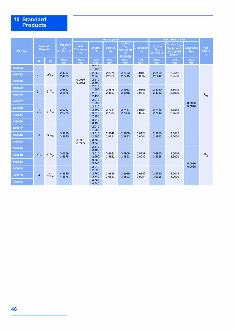
48
10 Standard Products
36DX32
21/4 27/162.43872.4375
0.09800.0962
2.0101.990
2.23782.2360
2.24632.2415
0.01030.0037
2.24602.2442
2.25122.2500
0.00700.0040
5/16
36DX36 2.2602.240
36DX40 2.5102.490
40DX3221/2 211/16
2.68872.6875
2.0101.990 2.4875
2.48572.49632.4915
0.01060.0040
2.49602.4942
2.50122.500040DX40 2.510
2.490
44DX32
23/4 215/162.93872.9375
0.09910.0965
2.0101.990
2.73512.7333
2.74572.7393
0.01240.0042
2.74602.7442
2.75122.7500
44DX40 2.5102.490
44DX48 3.010 2.990
44DX56 3.510 3.490
48DX32
3 33/163.18893.1875
2.0101.990
2.98492.9831
2.99592.9893
0.01280.0044
2.99602.9942
3.00123.0000
3/8
48DX48 3.0102.990
48DX60 3.7603.740
56DX40
31/2 311/163.68893.6875
2.5102.490
3.48443.4822
3.49593.4893
0.01370.0049
3.49503.4928
3.50143.5000
0.00860.0050
56DX48 3.0102.990
56DX60 3.7603.740
64DX48
4 43/164.18894.1875
3.0102.990
3.98393.9817
3.99593.9893
0.01420.0054
3.99503.9928
4.00144.000064DX60 3.760
3.740
64DX76 4.7604.740
Part No.
NominalDiameter
Housing-ø DH
[BS 1916 H7]
As supplied Machined in situ
Oil hole-ø
dL
WallThickness
s3
WidthB
Shaft-ø DJ
Bush-ø Di,a
Ass. in an H7
housing
ClearanceCD
Shaft-øDJm
[BS 1916 d8]
Bush-ø Di,am Machined in
situ to BS 1916 H7
Clearance CDm
Di Domax.min.
max.min.
max.min.
max. min.
max.min.
max.min.
max.min.
max.min.
max.min.

49
10Standard Products
10.5DX Thrust Washers - Inch sizes
All dimensions in inch
dP
Di
Do
sT
Ha
Do
d p
dD
Hd
[D10
]
DJ
Part No.
Inside-øDi
Outside-øDo
ThicknesssT
Dowel hole Recess depthHaø dD PCD-ø dP
max.min.
max.min.
max.min.
max.min.
max.min.
max.min.
DX06 0.51000.5000
0.87500.8650
0.06600.0625
0.07700.0670
0.69200.6820
0.0500.040
DX07 0.57200.5620
1.00000.9900
0.78600.7760
DX08 0.63500.6250
1.12501.1150
0.10900.0990
0.88000.8700
DX09 0.69700.6870
1.18701.1770
0.94200.9320
DX10 0.76000.7500
1.25001.2400
1.00500.9950
DX11 0.82200.8120
1.37501.3650
1.09901.0890
DX12 0.88500.8750
1.50001.4900 0.1400
0.1300
1.19201.1820
DX14 1.01001.0000
1.75001.7400
1.38001.3700
DX16 1.13501.1250
2.00001.9900
0.17100.1610
1.56701.5570
DX18 1.26001.2500
2.12502.1150
1.69201.6820
DX20 1.38501.3750
2.25002.2400
1.81701.8070
DX22 1.51001.5000
2.50002.4900
0.20200.1920
2.00501.9950
DX24 1.63501.6250
2.62502.6150
2.13002.1200
DX26 1.76001.7500
2.75002.7400
2.25502.2450
DX28 2.01002.0000
3.00002.9900
0.09700.0935
2.50502.4950
0.0800.070DX30 2.1350
2.12503.12503.1150
2.63002.6200
DX32 2.26002.2500
3.25003.2400
2.75502.7450
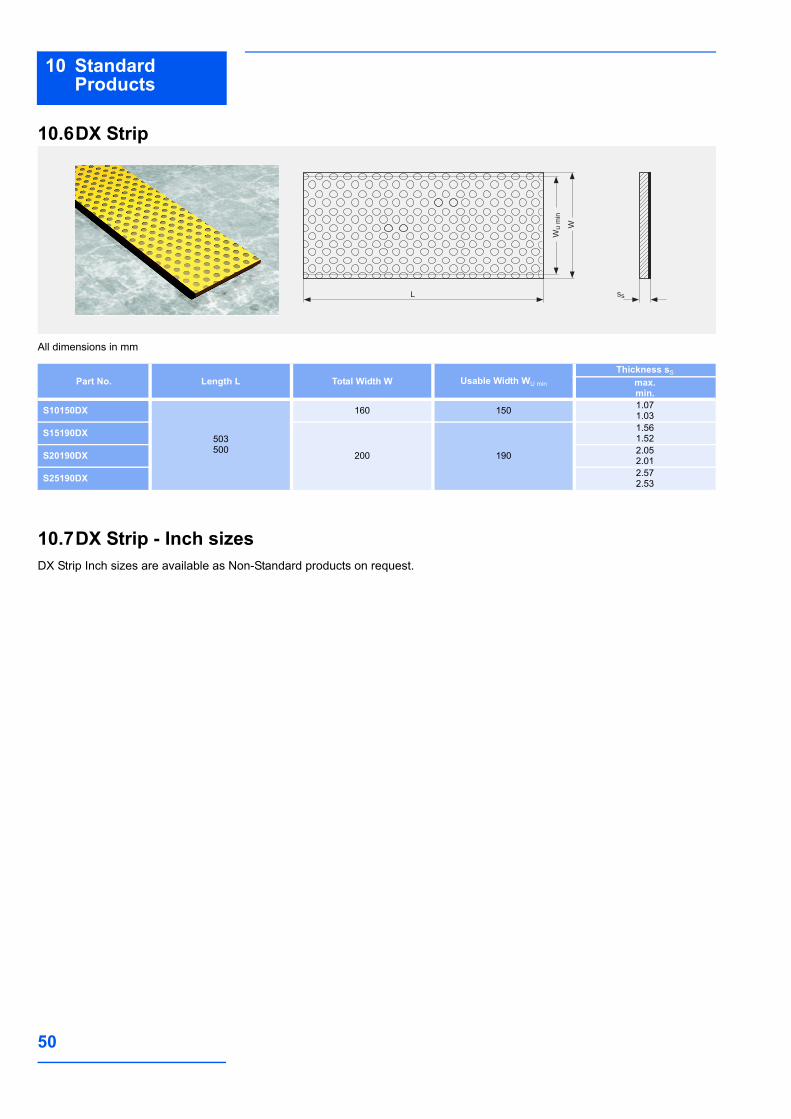
50
10 Standard Products
10.6DX Strip
All dimensions in mm
10.7DX Strip - Inch sizesDX Strip Inch sizes are available as Non-Standard products on request.
ss
Wu
min
L
W
Part No. Length L Total Width W Usable Width WU min
Thickness sS
max.min.
S10150DX
503500
160 150 1.071.03
S15190DX
200 190
1.561.52
S20190DX 2.052.01
S25190DX 2.572.53

©2008 GGB. All rights reserved.www.ggbearings.com
This handbook was designed by Profidoc Silvia Freitag
www.profidoc.de
02-08
GGB warrants that products described in this brochure are free from defects in workmanship and material but unless expressly agreed in wri-ting GGB gives no warranty that these products are suitable for any par-ticular purpose of for use under any specific conditions notwithstanding that such purpose would appear to be covered by this publication. GGB accepts no liability for any loss, damage, or expense whatsoever arising directly or indirectly from use of its products. All business undertaken by GGB is subject to its standard Conditions of Sale, copies of which are available upon request. GGB products are subject to continual develop-ment and GGB reserves the right to make changes in the specification and design of its products without prior notice.
GGBTM is a trademark of GGB.
DX® is a trademark of GGB.
DSTM is a trademark of GGB.
Declaration on the RoHS Directive
On July the 1st 2006 the EU directive 2002/95/EG (“RoHS-directive,Restriction of Hazardous Substances”) became effective. It forbids to place products into circulation that contain lead, cadmium, chrome (VI), mercury or PBB/PBDE containing flame retardants.All products of GGB except DU and DUB comply with the EU directives 2002/96/EG (End of life directive on electric and electronic devices) and 2002/95/EG (Constraint of certain hazardous materials in electric and electronic devices) and End of Life Vehicles directive (2000/53/EC) on the elimination of hazardous materials in the construction of passenger cars and light trucks.
Visit us on the internet:
www.ggbearings.com