Embed Size (px)
Citation preview
4-Port Cable/DSL Router
Manual
DX-E401DX-E401DX-E401DX-E401DX-E401
Published March 2004
2
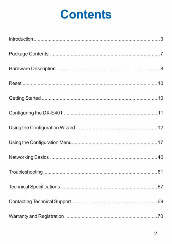
Contents
Introduction............................................................................................3
Package Contents ................................................................................7
Hardware Description ...........................................................................8
Reset ..................................................................................................10
Getting Started ....................................................................................10
Configuring the DX-E401 .................................................................... 11
Using the Configuration Wizard ...........................................................12
Using the Configuration Menu..............................................................17
Networking Basics ..............................................................................46
Troubleshooting...................................................................................61
Technical Specifications ......................................................................67
Contacting Technical Support ..............................................................69
Warranty and Registration ...................................................................70
3
IntroductionThe Dynex DX-E401 is a 4-port Cable/DSL Router. The Dynex DX-E401 enablesusers to quickly and easily share a high speed Internet connection. The DynexDX-E401 also incorporates many advanced features, traditionally found in moreexpensive routers.
After completing the steps outlined in the Quick Installation Guide (included inyour package) you will have the ability to share a single Internet connection aswell as sharing information and resources such as files and printers.
The DX-E401 is compatible with most popular operating systems, includingMacintosh, Linux and Windows, and can be integrated into an existing network.This Manual is designed to help you connect the Dynex DX-E401 to a highspeed Internet connection and 4 Ethernet PC connections.
This manual provides a quick introduction to Broadband Router Technology,Firewalls, and Local Area Networking. Please take a moment to read throughthis manual and get acquainted these various technologies.
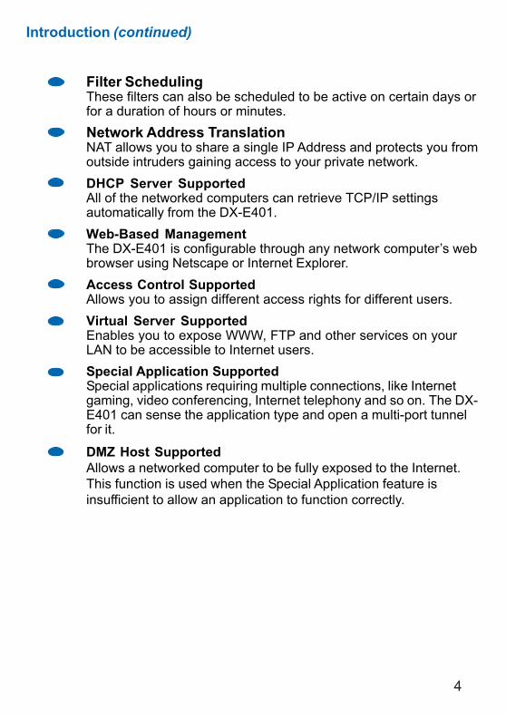
Features and BenefitsBroadband Modem and IP SharingConnects multiple computers to a Broadband (Cable or DSL)modem to share the Internet connection.Ethernet SwitchAllows you to quickly and easily share an Internet connection withmultiple computers and devices.VPN supportedSupports multiple and concurrent IPSec and PPTP pass-throughsessions, so multiple users behind the DX-E401 can accesscorporate networks through various VPN clients more securely.Advanced Firewall & Parental Control FeaturesThe Web-Based user interface displays a number of advancednetwork management features including:Content FilteringEasily applied content filtering based on Mac Address, IP Address,URL and/or Domain Name.
4
Introduction (continued)
Filter SchedulingThese filters can also be scheduled to be active on certain days orfor a duration of hours or minutes.Network Address TranslationNAT allows you to share a single IP Address and protects you fromoutside intruders gaining access to your private network.DHCP Server SupportedAll of the networked computers can retrieve TCP/IP settingsautomatically from the DX-E401.Web-Based ManagementThe DX-E401 is configurable through any network computer’s webbrowser using Netscape or Internet Explorer.Access Control SupportedAllows you to assign different access rights for different users.Virtual Server SupportedEnables you to expose WWW, FTP and other services on yourLAN to be accessible to Internet users.Special Application SupportedSpecial applications requiring multiple connections, like Internetgaming, video conferencing, Internet telephony and so on. The DX-E401 can sense the application type and open a multi-port tunnelfor it.
DMZ Host SupportedAllows a networked computer to be fully exposed to the Internet.This function is used when the Special Application feature isinsufficient to allow an application to function correctly.
5
Technology Introduction
Introduction (continued)
Introduction to Broadband Router TechnologyA router is a device that forwards data packets from a source to a destination.Routers forward data packets using IP addresses and not a MAC address. Arouter will forward data from the Internet to a particular computer on your LAN.The information that makes up the Internet gets moved around using routers.When you click on a link on a web page, you send a request to a server to showyou the next page. The information that is sent and received from your computeris moved from your computer to the server using routers. A router alsodetermines the best route that your information should follow to ensure that theinformation is delivered properly.
A router controls the amount of data that is sent through your network byeliminating information that should not be there. This provides security for thecomputers connected to your router, because computers from the outsidecannot access or send information directly to any computer on your network.The router determines which computer the information should be forwarded toand sends it. If the information is not intended for any computer on your network,the data is discarded. This keeps any unwanted or harmful information fromaccessing or damaging your network.
Introduction to FirewallsA firewall is a device that sits between your computer and the Internet thatprevents unauthorized access to or from your network. A firewall can be acomputer using firewall software or a special piece of hardware built specificallyto act as a firewall. In most circumstances, a firewall is used to preventunauthorized Internet users from accessing private networks or corporate LAN’sand Intranets.
A firewall watches all of the information moving to and from your network andanalyzes each piece of data. Each piece of data is checked against a set ofcriteria that the administrator configures. If any data does not meet the criteria,that data is blocked and discarded. If the data meets the criteria, the data ispassed through. This method is called packet filtering.
A firewall can also run specific security functions based on the type of applicationor type of port that is being used. For example, a firewall can be configured towork with an FTP or Telnet server. Or a firewall can be configured to work withspecific UDP or TCP ports to allow certain applications or games to workproperly over the Internet.
6
Introduction (continued)
Introduction to Local Area NetworkingLocal Area Networking (LAN) is the term used when connecting severalcomputers together over a small area such as a building or group of buildings.LAN’s can be connected over large areas. A collection of LAN’s connected overa large area is called a Wide Area Network (WAN).
A LAN consists of multiple computers connected to each other. There are manytypes of media that can connect computers together. The most common mediais Cat-5 cable (UTP or STP twisted pair wire.) On the other hand, wirelessnetworks do not use wires; instead they communicate over radio waves. Eachcomputer must have a Network Interface Card (NIC), which communicates thedata between computers. A NIC is usually a 10Mbps network card, or 10/100Mbps network card, or a wireless network card.
Most networks use hardware devices such as hubs or switches that each cablecan be connected to in order to continue the connection between computers. Ahub simply takes any data arriving through each port and forwards the data toall other ports. A switch is more sophisticated, in that a switch can determinethe destination port for a specific piece of data. A switch minimizes networktraffic overhead and speeds up the communication over a network.
Networks take some time in order to plan and implement correctly. There aremany ways to configure your network. You may want to take some time todetermine the best network set-up for your needs.
7
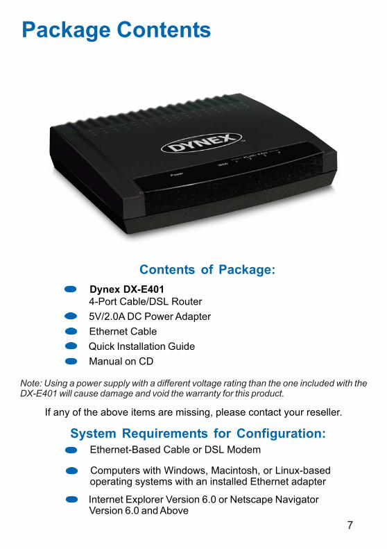
Internet Explorer Version 6.0 or Netscape NavigatorVersion 6.0 and Above
Contents of Package: Dynex DX-E401 4-Port Cable/DSL Router 5V/2.0A DC Power Adapter Ethernet Cable Quick Installation Guide Manual on CD
Computers with Windows, Macintosh, or Linux-based operating systems with an installed Ethernet adapter
Package Contents
Note: Using a power supply with a different voltage rating than the one included with theDX-E401 will cause damage and void the warranty for this product.
If any of the above items are missing, please contact your reseller.
System Requirements for Configuration: Ethernet-Based Cable or DSL Modem
8
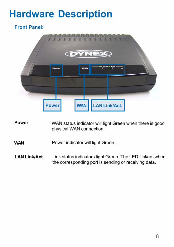
Hardware DescriptionFront Panel:
LAN Link/Act.
Power indicator will light Green.
WAN status indicator will light Green when there is goodphysical WAN connection.
Link status indicators light Green. The LED flickers whenthe corresponding port is sending or receiving data.
Power
WAN
Power WAN LAN Link/Act.
9
Hardware Description (continued)
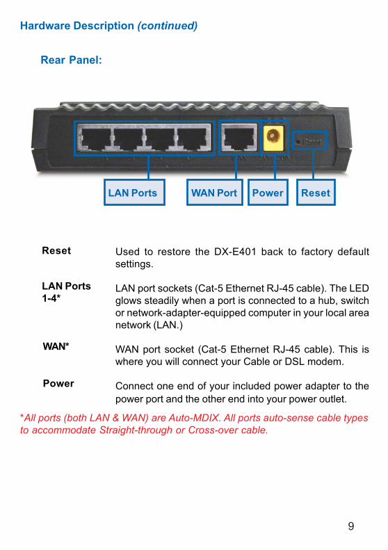
Rear Panel:
Used to restore the DX-E401 back to factory defaultsettings.
LAN port sockets (Cat-5 Ethernet RJ-45 cable). The LEDglows steadily when a port is connected to a hub, switchor network-adapter-equipped computer in your local areanetwork (LAN.)
WAN port socket (Cat-5 Ethernet RJ-45 cable). This iswhere you will connect your Cable or DSL modem.
Connect one end of your included power adapter to thepower port and the other end into your power outlet.
Reset
LAN Ports1-4*
WAN*
Power
*All ports (both LAN & WAN) are Auto-MDIX. All ports auto-sense cable typesto accommodate Straight-through or Cross-over cable.
WAN PortLAN Ports Power Reset
10
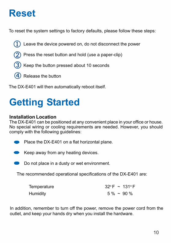
To reset the system settings to factory defaults, please follow these steps:
Leave the device powered on, do not disconnect the power
Press the reset button and hold (use a paper-clip)
Keep the button pressed about 10 seconds
Release the button
The DX-E401 will then automatically reboot itself.
Reset
Getting StartedInstallation LocationThe DX-E401 can be positioned at any convenient place in your office or house.No special wiring or cooling requirements are needed. However, you shouldcomply with the following guidelines:
Place the DX-E401 on a flat horizontal plane.
Keep away from any heating devices.
Do not place in a dusty or wet environment.
The recommended operational specifications of the DX-E401 are:
Temperature 32o F ~ 131o FHumidity 5 % ~ 90 %
In addition, remember to turn off the power, remove the power cord from theoutlet, and keep your hands dry when you install the hardware.
11
Getting Started (continued)Network SettingsTo use the DX-E401correctly, you have to properly configure the network settingsof your computers. The default IP address of the DX-E401 is 192.168.0.1, andthe default subnet mask is 255.255.255.0. These addresses can be changedas needed, but the default values are used in this manual. If the TCP/IPenvironment of your computer has not yet been configured, you can refer toConfiguring Your PCs to Connect to the DX-E401 to configure it.
For example:
Configure your computer IP as 192.168.0.3, subnet mask as255.255.255.0 and gateway as 192.168.0.1.
Or more conveniently
Configure your computers to obtain TCP/IP settings automaticallyfrom the DHCP server feature of the DX-E401.
Since the IP address of the DX-E401 is 192.168.0.1, the IP address of yourcomputer must be 192.168.0.X (where “X” is a number between 2 and 254.)Each computer on your network must have a different IP address within thatrange. The default gateway must be 192.168.0.1 (the IP address of the DX-E401).
Configuring the DX-E401The DX-E401 provides an embedded Web-based management utility makingit operating system independent. You can configure your DX-E401 through theNetscape Communicator or Internet Explorer browser in MS Windows,Macintosh, Linux or UNIX based platforms. All that is needed is a web browsersuch as Internet Explorer or Netscape Navigator version 4 and higher with JavaScript enabled.
Start-up and Log inActivate your web browser and type in the IP address of the DX-E401 into theLocation (for Netscape) or Address (for IE) field and press “Enter.” The defaultIP address of the DX-E401 is 192.168.0.1
For example: http://192.168.0.1 DX-E401- Microsoft Internet Explorer
12
After the connection is established, the logon screen will pop up. To log in as anadministrator, enter the username of “admin” and the password (there is nodefault password, leave it blank). Click the OK button. If the password is correct,the web-management interface will appear.
Configuring the DX-E401 (continued)
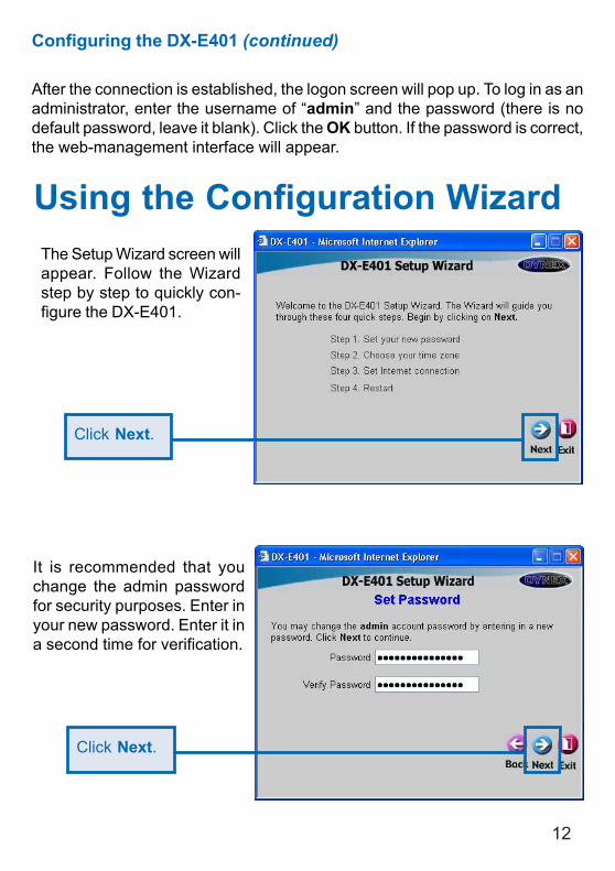
Using the Configuration WizardThe Setup Wizard screen willappear. Follow the Wizardstep by step to quickly con-figure the DX-E401.
Click Next.
It is recommended that youchange the admin passwordfor security purposes. Enter inyour new password. Enter it ina second time for verification.
Click Next.
13
Using the Configuration Wizard (continued)
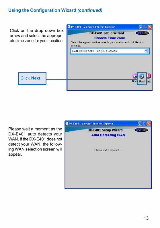
Click on the drop down boxarrow and select the appropri-ate time zone for your location.
Click Next.
Please wait a moment as theDX-E401 auto detects yourWAN. If the DX-E401 does notdetect your WAN, the follow-ing WAN selection screen willappear.
14
Using the Configuration Wizard (continued)
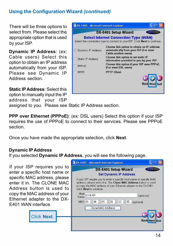
There will be three options toselect from. Please select theappropriate option that is usedby your ISP.
Dynamic IP Address: (ex:Cable users) Select thisoption to obtain an IP addressautomatically from your ISP.Please see Dynamic IPAddress section.
Static IP Address: Select thisoption to manually input the IPaddress that your ISPassigned to you. Please see Static IP Address section.
PPP over Ethernet (PPPoE): (ex: DSL users) Select this option if your ISPrequires the use of PPPoE to connect to their services. Please see PPPoEsection.
Once you have made the appropriate selection, click Next.
Dynamic IP AddressIf you selected Dynamic IP Address, you will see the following page.
If your ISP requires you toenter a specific host name orspecific MAC address, pleaseenter it in. The CLONE MACAddress button is used tocopy the MAC address of yourEthernet adapter to the DX-E401 WAN interface.
Click Next.
15
Using the Configuration Wizard (continued)
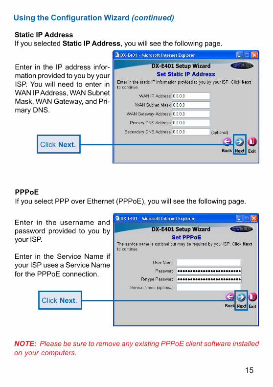
Static IP AddressIf you selected Static IP Address, you will see the following page.
Enter in the IP address infor-mation provided to you by yourISP. You will need to enter inWAN IP Address, WAN SubnetMask, WAN Gateway, and Pri-mary DNS.
Click Next.
PPPoEIf you select PPP over Ethernet (PPPoE), you will see the following page.
Enter in the username andpassword provided to you byyour ISP.
Enter in the Service Name ifyour ISP uses a Service Namefor the PPPoE connection.
Click Next.
NOTE: Please be sure to remove any existing PPPoE client software installedon your computers.
16
Using the Configuration Wizard (continued)
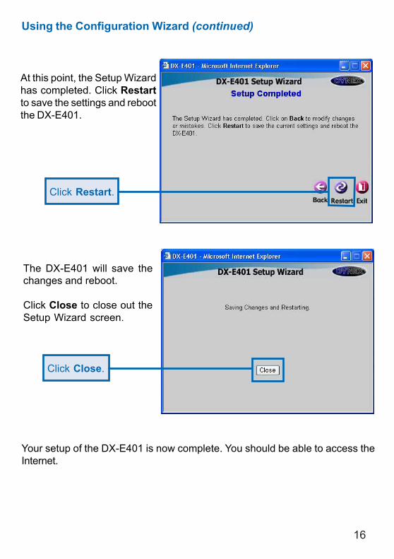
Click Restart.
At this point, the Setup Wizardhas completed. Click Restartto save the settings and rebootthe DX-E401.
The DX-E401 will save thechanges and reboot.
Click Close to close out theSetup Wizard screen.
Click Close.
Your setup of the DX-E401 is now complete. You should be able to access theInternet.
17
Type admin in the UserName fieldLeave the Password blankClick OK
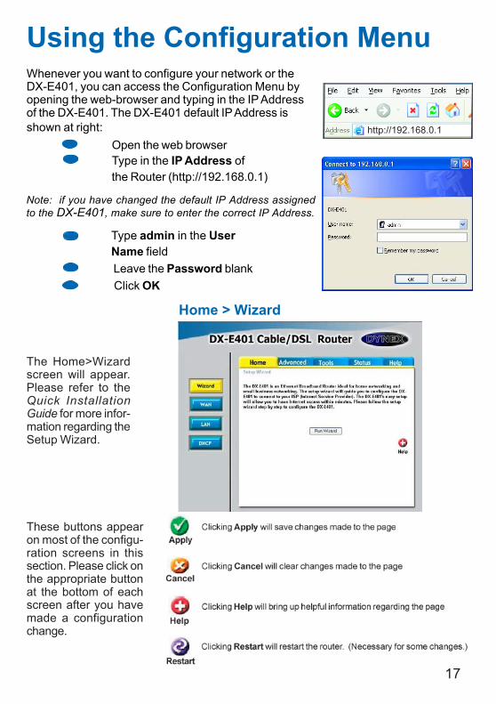
Whenever you want to configure your network or theDX-E401, you can access the Configuration Menu byopening the web-browser and typing in the IP Addressof the DX-E401. The DX-E401 default IP Address isshown at right:
Open the web browserType in the IP Address ofthe Router (http://192.168.0.1)
Using the Configuration Menu
Home > Wizard
The Home>Wizardscreen will appear.Please refer to theQuick InstallationGuide for more infor-mation regarding theSetup Wizard.
Note: if you have changed the default IP Address assignedto the DX-E401, make sure to enter the correct IP Address.
These buttons appearon most of the configu-ration screens in thissection. Please click onthe appropriate buttonat the bottom of eachscreen after you havemade a configurationchange.
http://192.168.0.1
18
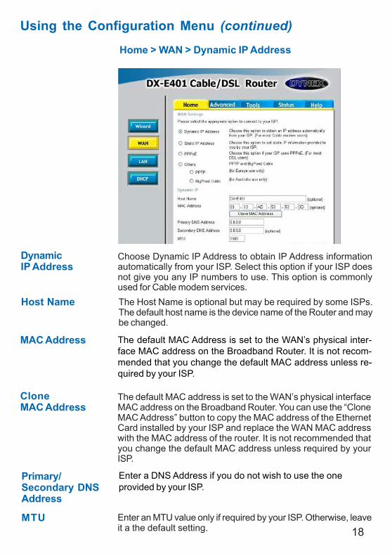
Using the Configuration Menu (continued)
Home > WAN > Dynamic IP Address
Host Name The Host Name is optional but may be required by some ISPs.The default host name is the device name of the Router and maybe changed.
MAC Address The default MAC Address is set to the WAN’s physical inter-face MAC address on the Broadband Router. It is not recom-mended that you change the default MAC address unless re-quired by your ISP.
CloneMAC Address
The default MAC address is set to the WAN’s physical interfaceMAC address on the Broadband Router. You can use the “CloneMAC Address” button to copy the MAC address of the EthernetCard installed by your ISP and replace the WAN MAC addresswith the MAC address of the router. It is not recommended thatyou change the default MAC address unless required by yourISP.
DynamicIP Address
Choose Dynamic IP Address to obtain IP Address informationautomatically from your ISP. Select this option if your ISP doesnot give you any IP numbers to use. This option is commonlyused for Cable modem services.
Primary/Secondary DNSAddress
Enter an MTU value only if required by your ISP. Otherwise, leaveit a the default setting.
MTU
Enter a DNS Address if you do not wish to use the oneprovided by your ISP.
19
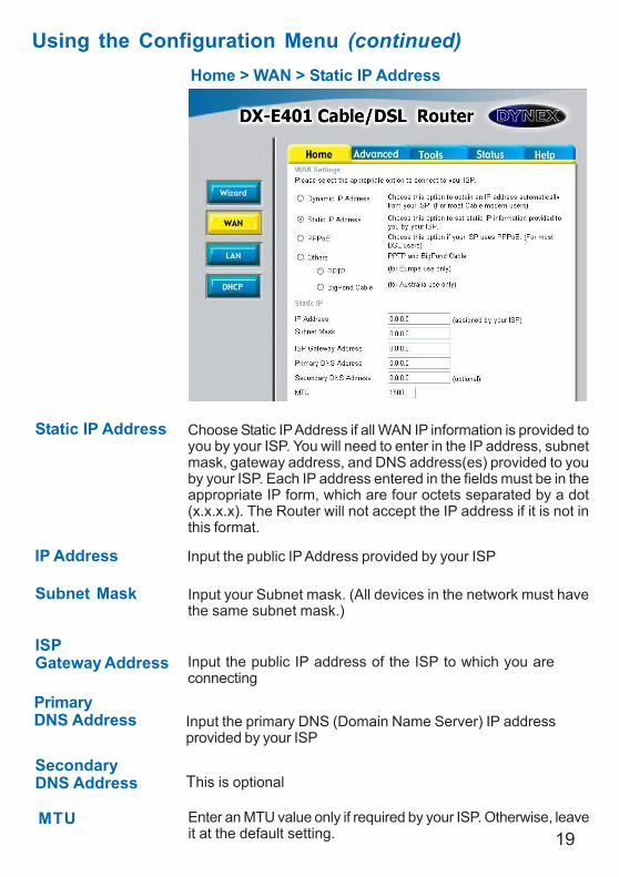
Using the Configuration Menu (continued)Home > WAN > Static IP Address
Static IP Address
IP Address
Subnet Mask
ISPGateway Address
PrimaryDNS Address
SecondaryDNS Address
Choose Static IP Address if all WAN IP information is provided toyou by your ISP. You will need to enter in the IP address, subnetmask, gateway address, and DNS address(es) provided to youby your ISP. Each IP address entered in the fields must be in theappropriate IP form, which are four octets separated by a dot(x.x.x.x). The Router will not accept the IP address if it is not inthis format.
Input the public IP Address provided by your ISP
Input your Subnet mask. (All devices in the network must havethe same subnet mask.)
Input the public IP address of the ISP to which you areconnecting
Input the primary DNS (Domain Name Server) IP addressprovided by your ISP
This is optional
Enter an MTU value only if required by your ISP. Otherwise, leaveit at the default setting.
MTU
20
Using the Configuration Menu (continued)Home > WAN > PPPoE
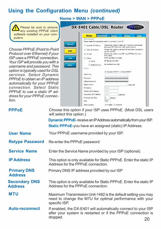
IP Address This option is only available for Static PPPoE. Enter the static IPAddress for the PPPoE connection.
User Name Your PPPoE username provided by your ISP.
Service Name Enter the Service Name provided by your ISP (optional).
Retype Password Re-enter the PPPoE password
PPPoE
Static PPPoE-you have an assigned (static) IP Address.
Choose this option if your ISP uses PPPoE. (Most DSL userswill select this option.)Dynamic PPPoE- receive an IP Address automatically from your ISP.
Primary DNSAddress
Primary DNS IP address provided by our ISP
Secondary DNSAddress
This option is only available for Static PPPoE. Enter the static IPAddress for the PPPoE connection.
Choose PPPoE (Point to PointProtocol over Ethernet) if yourISP uses a PPPoE connection.Your ISP will provide you with ausername and password. Thisoption is typically used for DSLservices. Select DynamicPPPoE to obtain an IP addressautomatically for your PPPoEconnection. Select StaticPPPoE to use a static IP ad-dress for your PPPoE connec-tion.
Please be sure to removeany existing PPPoE client
software installed on your com-puters.
Auto-reconnect If enabled, the DX-E401 will automatically connect to your ISPafter your system is restarted or if the PPPoE connection isdropped.
MTU Maximum Transmission Unit-1492 is the default setting-you mayneed to change the MTU for optimal performance with yourspecific ISP.
21
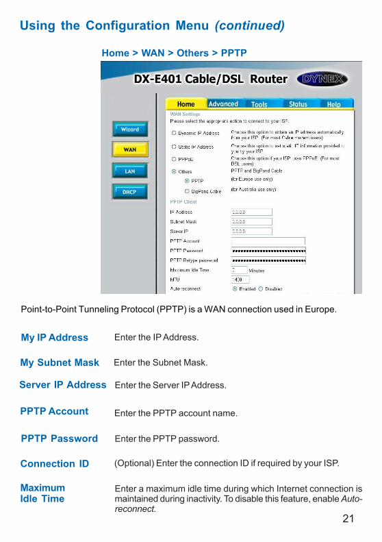
Home > WAN > Others > PPTP
Using the Configuration Menu (continued)
PPTP Password Enter the PPTP password.
PPTP Account Enter the PPTP account name.
My Subnet Mask
Connection ID (Optional) Enter the connection ID if required by your ISP.
MaximumIdle Time
Enter a maximum idle time during which Internet connection ismaintained during inactivity. To disable this feature, enable Auto-reconnect.
My IP Address Enter the IP Address.
Server IP Address Enter the Server IP Address.
Point-to-Point Tunneling Protocol (PPTP) is a WAN connection used in Europe.
Enter the Subnet Mask.
22
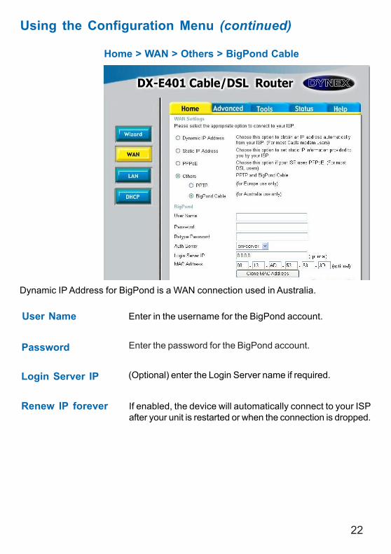
Home > WAN > Others > BigPond Cable
User Name Enter in the username for the BigPond account.
Password Enter the password for the BigPond account.
Login Server IP (Optional) enter the Login Server name if required.
Renew IP forever If enabled, the device will automatically connect to your ISPafter your unit is restarted or when the connection is dropped.
Dynamic IP Address for BigPond is a WAN connection used in Australia.
Using the Configuration Menu (continued)
23
Using the Configuration Menu (continued)
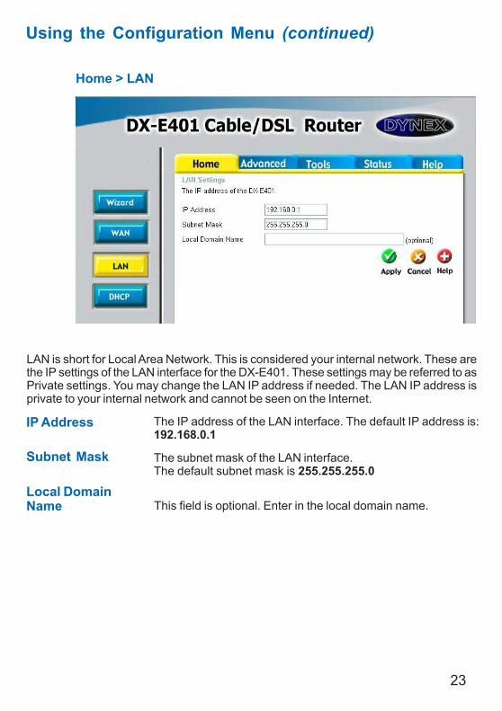
Home > LAN
LAN is short for Local Area Network. This is considered your internal network. These arethe IP settings of the LAN interface for the DX-E401. These settings may be referred to asPrivate settings. You may change the LAN IP address if needed. The LAN IP address isprivate to your internal network and cannot be seen on the Internet.
Local DomainName This field is optional. Enter in the local domain name.
Subnet Mask The subnet mask of the LAN interface.The default subnet mask is 255.255.255.0
IP Address The IP address of the LAN interface. The default IP address is:192.168.0.1
24
Using the Configuration Menu (continued)
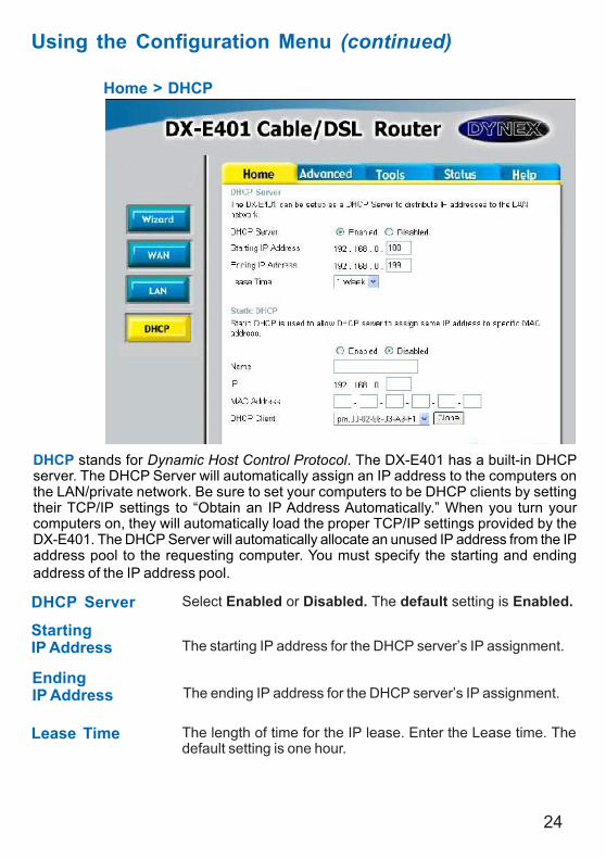
Home > DHCP
DHCP stands for Dynamic Host Control Protocol. The DX-E401 has a built-in DHCPserver. The DHCP Server will automatically assign an IP address to the computers onthe LAN/private network. Be sure to set your computers to be DHCP clients by settingtheir TCP/IP settings to “Obtain an IP Address Automatically.” When you turn yourcomputers on, they will automatically load the proper TCP/IP settings provided by theDX-E401. The DHCP Server will automatically allocate an unused IP address from the IPaddress pool to the requesting computer. You must specify the starting and endingaddress of the IP address pool.
DHCP Server Select Enabled or Disabled. The default setting is Enabled.
StartingIP Address The starting IP address for the DHCP server’s IP assignment.
EndingIP Address The ending IP address for the DHCP server’s IP assignment.
Lease Time The length of time for the IP lease. Enter the Lease time. Thedefault setting is one hour.
DI-754
25
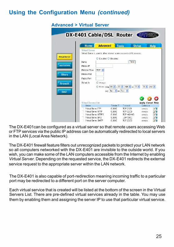
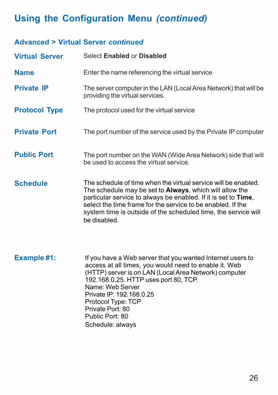
Advanced > Virtual Server
Using the Configuration Menu (continued)
The DX-E401can be configured as a virtual server so that remote users accessing Webor FTP services via the public IP address can be automatically redirected to local serversin the LAN (Local Area Network).
The DX-E401 firewall feature filters out unrecognized packets to protect your LAN networkso all computers networked with the DX-E401 are invisible to the outside world. If youwish, you can make some of the LAN computers accessible from the Internet by enablingVirtual Server. Depending on the requested service, the DX-E401 redirects the externalservice request to the appropriate server within the LAN network.
The DX-E401 is also capable of port-redirection meaning incoming traffic to a particularport may be redirected to a different port on the server computer.
Each virtual service that is created will be listed at the bottom of the screen in the VirtualServers List. There are pre-defined virtual services already in the table. You may usethem by enabling them and assigning the server IP to use that particular virtual service.
26
Advanced > Virtual Server continued
Using the Configuration Menu (continued)
Example #1:
Protocol Type The protocol used for the virtual service
Public Port The port number on the WAN (Wide Area Network) side that willbe used to access the virtual service.
Private Port The port number of the service used by the Private IP computer
Schedule The schedule of time when the virtual service will be enabled.The schedule may be set to Always, which will allow theparticular service to always be enabled. If it is set to Time,select the time frame for the service to be enabled. If thesystem time is outside of the scheduled time, the service willbe disabled.
Virtual Server Select Enabled or Disabled
Name Enter the name referencing the virtual service
Private IP The server computer in the LAN (Local Area Network) that will beproviding the virtual services.
If you have a Web server that you wanted Internet users toaccess at all times, you would need to enable it. Web(HTTP) server is on LAN (Local Area Network) computer192.168.0.25. HTTP uses port 80, TCP.Name: Web ServerPrivate IP: 192.168.0.25Protocol Type: TCPPrivate Port: 80Public Port: 80Schedule: always
27
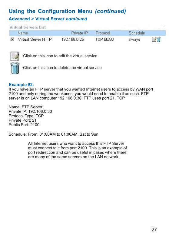
Example #2:If you have an FTP server that you wanted Internet users to access by WAN port2100 and only during the weekends, you would need to enable it as such. FTPserver is on LAN computer 192.168.0.30. FTP uses port 21, TCP.
Name: FTP ServerPrivate IP: 192.168.0.30Protocol Type: TCPPrivate Port: 21Public Port: 2100
Schedule: From: 01:00AM to 01:00AM, Sat to Sun
Using the Configuration Menu (continued)Advanced > Virtual Server continued
Click on this icon to edit the virtual service
Click on this icon to delete the virtual service
All Internet users who want to access this FTP Servermust connect to it from port 2100. This is an example ofport redirection and can be useful in cases where thereare many of the same servers on the LAN network.
28
Using the Configuration Menu (continued)
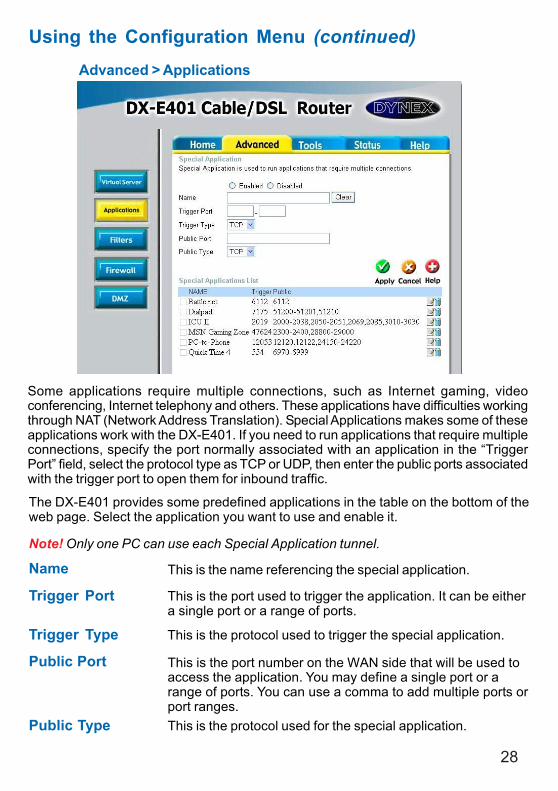
Advanced > Applications
Some applications require multiple connections, such as Internet gaming, videoconferencing, Internet telephony and others. These applications have difficulties workingthrough NAT (Network Address Translation). Special Applications makes some of theseapplications work with the DX-E401. If you need to run applications that require multipleconnections, specify the port normally associated with an application in the “TriggerPort” field, select the protocol type as TCP or UDP, then enter the public ports associatedwith the trigger port to open them for inbound traffic.
The DX-E401 provides some predefined applications in the table on the bottom of theweb page. Select the application you want to use and enable it.
Note! Only one PC can use each Special Application tunnel.
Name This is the name referencing the special application.
Trigger Port This is the port used to trigger the application. It can be eithera single port or a range of ports.
Trigger Type This is the protocol used to trigger the special application.
Public Port This is the port number on the WAN side that will be used toaccess the application. You may define a single port or arange of ports. You can use a comma to add multiple ports orport ranges.
Public Type This is the protocol used for the special application.
29
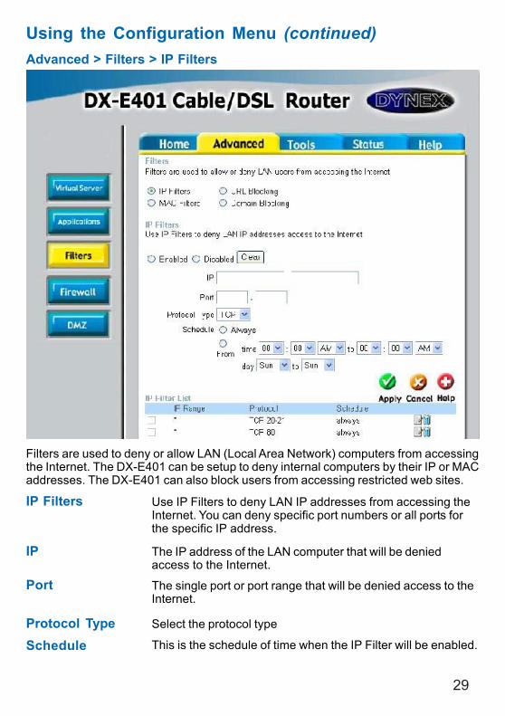
Using the Configuration Menu (continued)Advanced > Filters > IP Filters
Filters are used to deny or allow LAN (Local Area Network) computers from accessingthe Internet. The DX-E401 can be setup to deny internal computers by their IP or MACaddresses. The DX-E401 can also block users from accessing restricted web sites.
This is the schedule of time when the IP Filter will be enabled.ScheduleSelect the protocol typeProtocol Type
Use IP Filters to deny LAN IP addresses from accessing theInternet. You can deny specific port numbers or all ports forthe specific IP address.
IP Filters
The single port or port range that will be denied access to theInternet.
Port
The IP address of the LAN computer that will be deniedaccess to the Internet.
IP
30
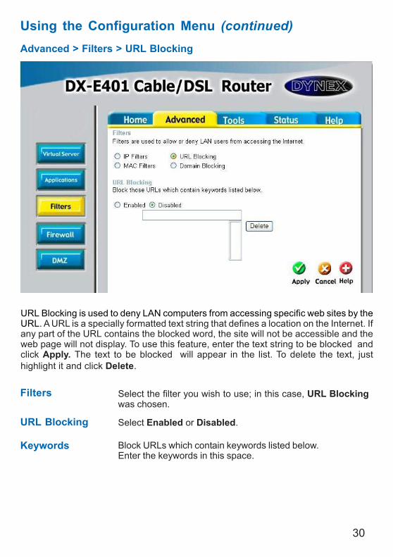
Using the Configuration Menu (continued)Advanced > Filters > URL Blocking
Filters
URL Blocking is used to deny LAN computers from accessing specific web sites by theURL. A URL is a specially formatted text string that defines a location on the Internet. Ifany part of the URL contains the blocked word, the site will not be accessible and theweb page will not display. To use this feature, enter the text string to be blocked andclick Apply. The text to be blocked will appear in the list. To delete the text, justhighlight it and click Delete.
Select the filter you wish to use; in this case, URL Blockingwas chosen.
Keywords Block URLs which contain keywords listed below.Enter the keywords in this space.
URL Blocking Select Enabled or Disabled.
31
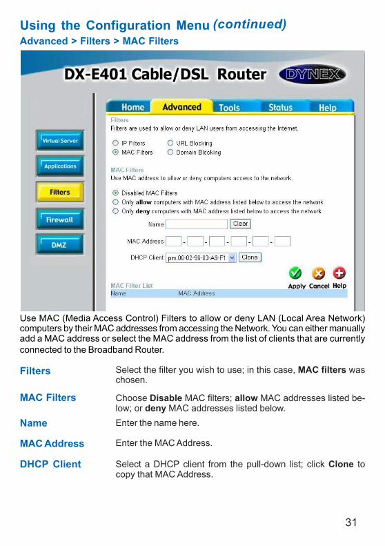
Using the Configuration MenuAdvanced > Filters > MAC Filters
Use MAC (Media Access Control) Filters to allow or deny LAN (Local Area Network)computers by their MAC addresses from accessing the Network. You can either manuallyadd a MAC address or select the MAC address from the list of clients that are currentlyconnected to the Broadband Router.
MAC Filters Choose Disable MAC filters; allow MAC addresses listed be-low; or deny MAC addresses listed below.
Filters
Name Enter the name here.
MAC Address Enter the MAC Address.
DHCP Client Select a DHCP client from the pull-down list; click Clone tocopy that MAC Address.
Select the filter you wish to use; in this case, MAC filters waschosen.
(continued)
32
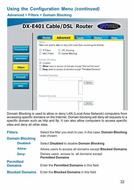
Using the Configuration MenuAdvanced > Filters > Domain Blocking
Filters
Domain Blocking
Blocked Domains
PermittedDomains
Domain Blocking is used to allow or deny LAN (Local Area Network) computers fromaccessing specific domains on the Internet. Domain blocking will deny all requests to aspecific domain such as http and ftp. It can also allow computers to access specificsites and deny all other sites.
Select the filter you wish to use; in this case, Domain Blockingwas chosen.
Disabled-Allow-Deny-
Enter the Permitted Domains in this field
Enter the Blocked Domains in this field
Select Disabled to disable Domain Blocking
Allows users to access all domains except Blocked DomainsDenies users access to all domains exceptPermitted Domains
(continued)
33
Using the Configuration Menu (continued)Advanced > Firewall
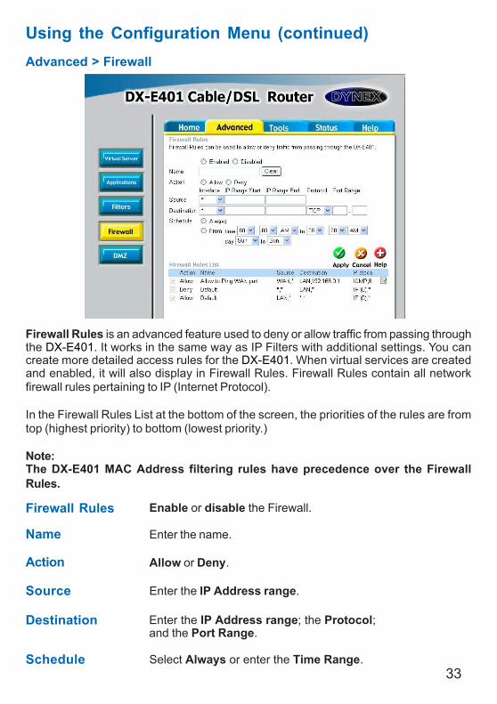
Firewall Rules is an advanced feature used to deny or allow traffic from passing throughthe DX-E401. It works in the same way as IP Filters with additional settings. You cancreate more detailed access rules for the DX-E401. When virtual services are createdand enabled, it will also display in Firewall Rules. Firewall Rules contain all networkfirewall rules pertaining to IP (Internet Protocol).
In the Firewall Rules List at the bottom of the screen, the priorities of the rules are fromtop (highest priority) to bottom (lowest priority.)
Note:The DX-E401 MAC Address filtering rules have precedence over the FirewallRules.
Firewall Rules Enable or disable the Firewall.
Name Enter the name.
Action Allow or Deny.
Source Enter the IP Address range.
Schedule Select Always or enter the Time Range.
Destination Enter the IP Address range; the Protocol;and the Port Range.
34
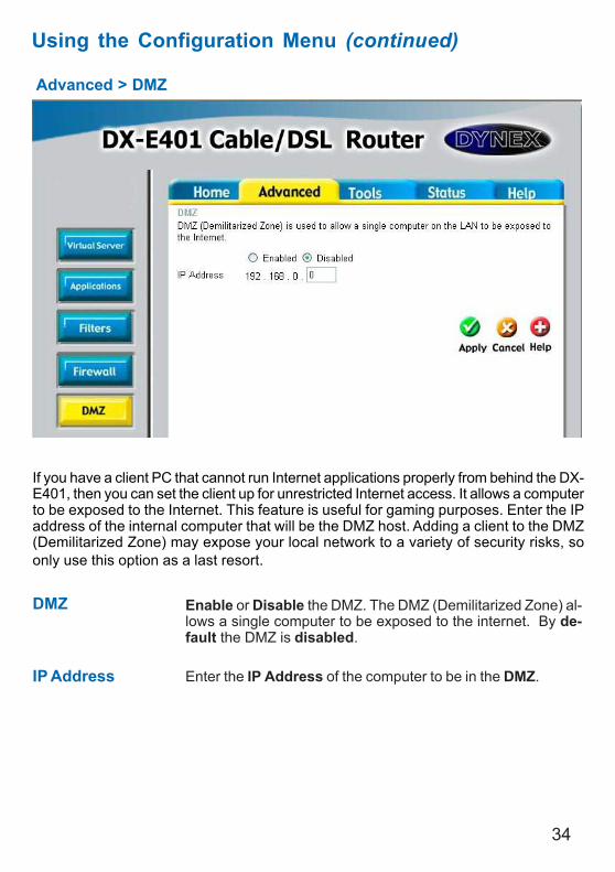
Advanced > DMZ
Using the Configuration Menu (continued)
If you have a client PC that cannot run Internet applications properly from behind the DX-E401, then you can set the client up for unrestricted Internet access. It allows a computerto be exposed to the Internet. This feature is useful for gaming purposes. Enter the IPaddress of the internal computer that will be the DMZ host. Adding a client to the DMZ(Demilitarized Zone) may expose your local network to a variety of security risks, soonly use this option as a last resort.
DMZ Enable or Disable the DMZ. The DMZ (Demilitarized Zone) al-lows a single computer to be exposed to the internet. By de-fault the DMZ is disabled.
IP Address Enter the IP Address of the computer to be in the DMZ.
35
Using the Configuration Menu (continued)
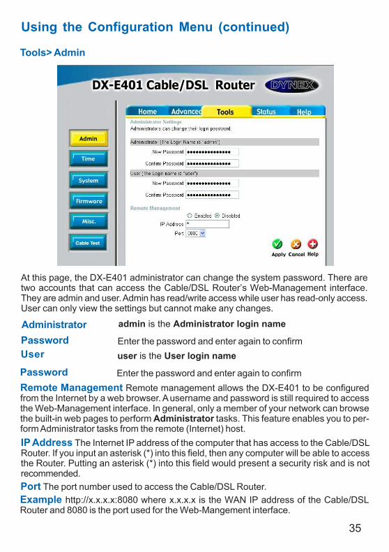
Tools> Admin
At this page, the DX-E401 administrator can change the system password. There aretwo accounts that can access the Cable/DSL Router’s Web-Management interface.They are admin and user. Admin has read/write access while user has read-only access.User can only view the settings but cannot make any changes.
Remote Management Remote management allows the DX-E401 to be configuredfrom the Internet by a web browser. A username and password is still required to accessthe Web-Management interface. In general, only a member of your network can browsethe built-in web pages to perform Administrator tasks. This feature enables you to per-form Administrator tasks from the remote (Internet) host.IP Address The Internet IP address of the computer that has access to the Cable/DSLRouter. If you input an asterisk (*) into this field, then any computer will be able to accessthe Router. Putting an asterisk (*) into this field would present a security risk and is notrecommended.Port The port number used to access the Cable/DSL Router.Example http://x.x.x.x:8080 where x.x.x.x is the WAN IP address of the Cable/DSLRouter and 8080 is the port used for the Web-Mangement interface.
AdministratorPassword
admin is the Administrator login name
Enter the password and enter again to confirmUser
Passworduser is the User login name
Enter the password and enter again to confirm
36
Using the Configuration Menu (continued)
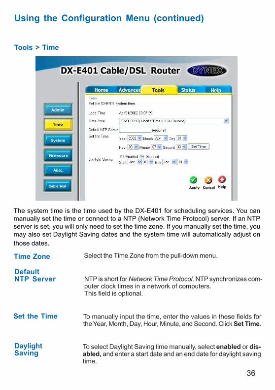
Tools > Time
Time Zone Select the Time Zone from the pull-down menu.
DaylightSaving
To select Daylight Saving time manually, select enabled or dis-abled, and enter a start date and an end date for daylight savingtime.
Set the Time To manually input the time, enter the values in these fields forthe Year, Month, Day, Hour, Minute, and Second. Click Set Time.
DefaultNTP Server NTP is short for Network Time Protocol. NTP synchronizes com-
puter clock times in a network of computers.This field is optional.
The system time is the time used by the DX-E401 for scheduling services. You canmanually set the time or connect to a NTP (Network Time Protocol) server. If an NTPserver is set, you will only need to set the time zone. If you manually set the time, youmay also set Daylight Saving dates and the system time will automatically adjust onthose dates.
37
Using the Configuration Menu (continued)
Tools > System
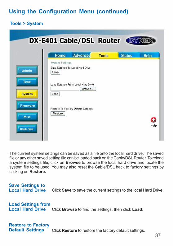
The current system settings can be saved as a file onto the local hard drive. The savedfile or any other saved setting file can be loaded back on the Cable/DSL Router. To reloada system settings file, click on Browse to browse the local hard drive and locate thesystem file to be used. You may also reset the Cable/DSL back to factory settings byclicking on Restore.
Click Save to save the current settings to the local Hard Drive.
Click Browse to find the settings, then click Load.
Save Settings toLocal Hard Drive
Load Settings fromLocal Hard Drive
Restore to FactoryDefault Settings Click Restore to restore the factory default settings.
38
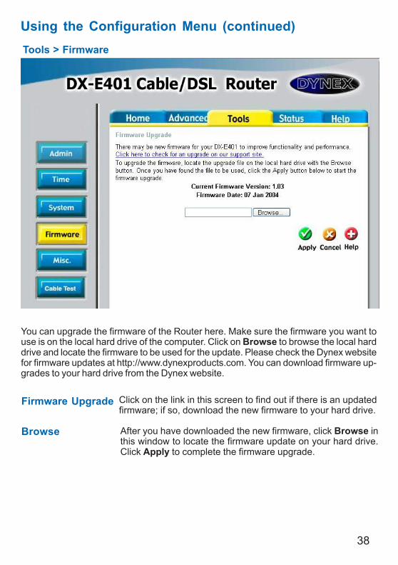
Using the Configuration Menu (continued)Tools > Firmware
You can upgrade the firmware of the Router here. Make sure the firmware you want touse is on the local hard drive of the computer. Click on Browse to browse the local harddrive and locate the firmware to be used for the update. Please check the Dynex websitefor firmware updates at http://www.dynexproducts.com. You can download firmware up-grades to your hard drive from the Dynex website.
Firmware Upgrade
Browse
Click on the link in this screen to find out if there is an updatedfirmware; if so, download the new firmware to your hard drive.
After you have downloaded the new firmware, click Browse inthis window to locate the firmware update on your hard drive.Click Apply to complete the firmware upgrade.
39
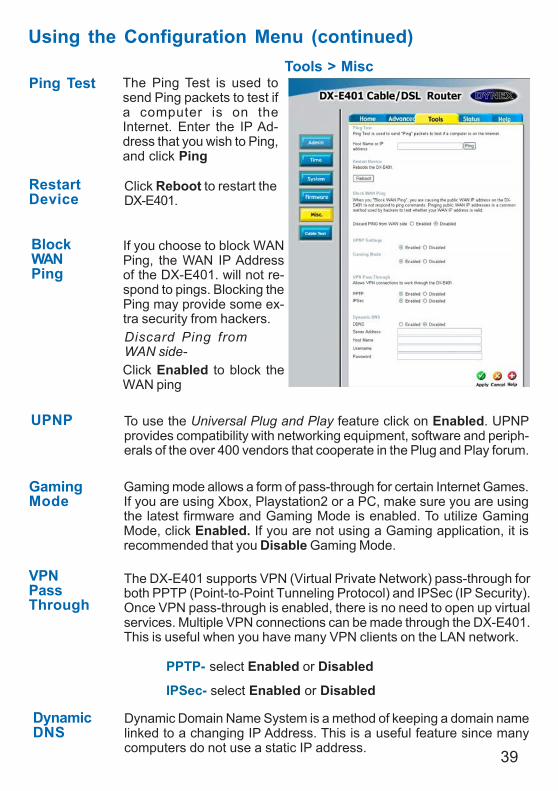
Using the Configuration Menu (continued)Tools > Misc
Ping Test
RestartDevice
BlockWANPing
Discard Ping fromWAN side-
The Ping Test is used tosend Ping packets to test ifa computer is on theInternet. Enter the IP Ad-dress that you wish to Ping,and click Ping
If you choose to block WANPing, the WAN IP Addressof the DX-E401. will not re-spond to pings. Blocking thePing may provide some ex-tra security from hackers.
Click Reboot to restart theDX-E401.
Click Enabled to block theWAN ping
UPNP
GamingMode
DynamicDNS
To use the Universal Plug and Play feature click on Enabled. UPNPprovides compatibility with networking equipment, software and periph-erals of the over 400 vendors that cooperate in the Plug and Play forum.
Gaming mode allows a form of pass-through for certain Internet Games.If you are using Xbox, Playstation2 or a PC, make sure you are usingthe latest firmware and Gaming Mode is enabled. To utilize GamingMode, click Enabled. If you are not using a Gaming application, it isrecommended that you Disable Gaming Mode.
Dynamic Domain Name System is a method of keeping a domain namelinked to a changing IP Address. This is a useful feature since manycomputers do not use a static IP address.
VPNPassThrough
PPTP- select Enabled or Disabled
IPSec- select Enabled or Disabled
The DX-E401 supports VPN (Virtual Private Network) pass-through forboth PPTP (Point-to-Point Tunneling Protocol) and IPSec (IP Security).Once VPN pass-through is enabled, there is no need to open up virtualservices. Multiple VPN connections can be made through the DX-E401.This is useful when you have many VPN clients on the LAN network.
40
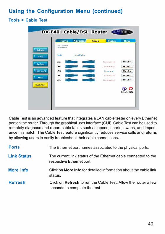
Using the Configuration Menu (continued)Tools > Cable Test
Ports
Link Status
The Ethernet port names associated to the physical ports.
The current link status of the Ethernet cable connected to therespective Ethernet port.
Cable Test is an advanced feature that integrates a LAN cable tester on every Ethernetport on the router. Through the graphical user interface (GUI), Cable Test can be used toremotely diagnose and report cable faults such as opens, shorts, swaps, and imped-ance mismatch. The Cable Test feature significantly reduces service calls and returnsby allowing users to easily troubleshoot their cable connections.
More Info Click on More Info for detailed information about the cable linkstatus.
Refresh Click on Refresh to run the Cable Test. Allow the router a fewseconds to complete the test.
41
Using the Configuration Menu (continued)
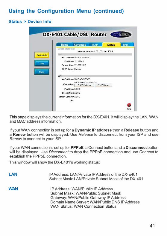
Status > Device Info
This page displays the current information for the DX-E401. It will display the LAN, WANand MAC address information.
If your WAN connection is set up for a Dynamic IP address then a Release button anda Renew button will be displayed. Use Release to disconnect from your ISP and useRenew to connect to your ISP.
If your WAN connection is set up for PPPoE, a Connect button and a Disconnect buttonwill be displayed. Use Disconnect to drop the PPPoE connection and use Connect toestablish the PPPoE connection.This window will show the DX-E401’s working status:
IP Address: LAN/Private IP Address of the DX-E401Subnet Mask: LAN/Private Subnet Mask of the DX-401
LAN
IP Address: WAN/Public IP AddressSubnet Mask: WAN/Public Subnet MaskGateway: WAN/Public Gateway IP AddressDomain Name Server: WAN/Public DNS IP AddressWAN Status: WAN Connection Status
WAN
42
The Cable/DSL Router keeps a running log of events and activities occurring on theRouter. If the device is rebooted, the logs are automatically cleared. You may save the logfiles under Log Settings.
Using the Configuration Menu (continued)Status > Log
View Log First Page - The first page of the logLast Page - The last page of the logPrevious - Moves back one log pageNext - Moves forward one log pageClear - Clears the logs completelyLog Settings - Brings up the page to configure the log
43
Status > Log > Log Settings
Email Address Enter in the email address of the recipient who will receive theemail log.
SMTP Server /IP Address
The address of the SMTP server that will be used to send thelogs.
Send Mail Now Click to send mail immediately.
Log Type Select the types of activity to log. By default, all values areselected.
Not only does the Cable/DSL Router display the logs of activities and events, it can besetup to send these logs to another location. The logs can be sent via email to an emailaccount.
Using the Configuration Menu (continued)
44
Using the Configuration Menu (continued)Status > Stats
The screen above displays theTraffic Statistics. Here you can view the amount of pack-ets that pass through the DX-E401 on both the WAN and the LAN ports. The trafficcounter will reset if the device is rebooted.
Refresh This will update the page.
Reset This will reset the packet counter to zero.
WAN Displays Received / Transmitted packets from the WAN port.
LAN Displays Received / Transmitted packets from the LAN port.
45
Using the Configuration MenuHelp
This screen displays the complete Help menu. For help at anytime, click the Help tabin the Configuration menu.
46
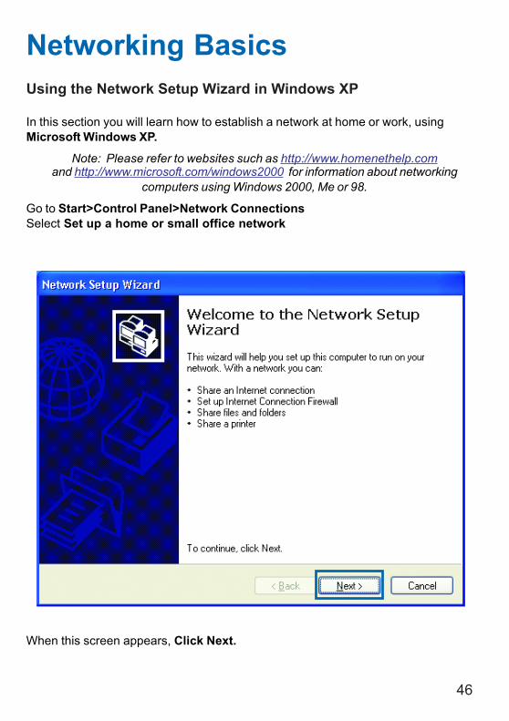
Using the Network Setup Wizard in Windows XP
In this section you will learn how to establish a network at home or work, usingMicrosoft Windows XP.
Note: Please refer to websites such as http://www.homenethelp.comand http://www.microsoft.com/windows2000 for information about networking
computers using Windows 2000, Me or 98.
Go to Start>Control Panel>Network ConnectionsSelect Set up a home or small office network
Networking Basics
When this screen appears, Click Next.
47
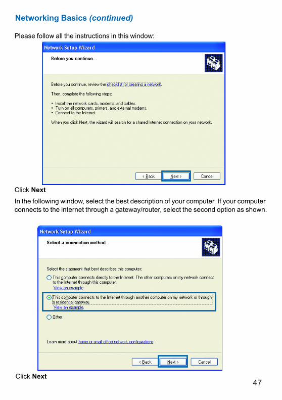
Please follow all the instructions in this window:
Click NextIn the following window, select the best description of your computer. If your computerconnects to the internet through a gateway/router, select the second option as shown.
Click Next
Networking Basics (continued)
48
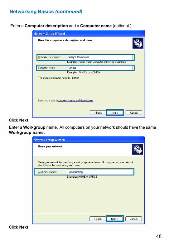
Enter a Computer description and a Computer name (optional.)
Click NextEnter a Workgroup name. All computers on your network should have the sameWorkgroup name.
Click Next
Networking Basics (continued)
49
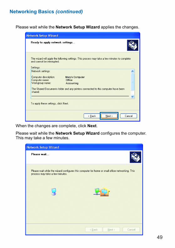
Please wait while the Network Setup Wizard applies the changes.
When the changes are complete, click Next.
Please wait while the Network Setup Wizard configures the computer.This may take a few minutes.
Networking Basics (continued)
50
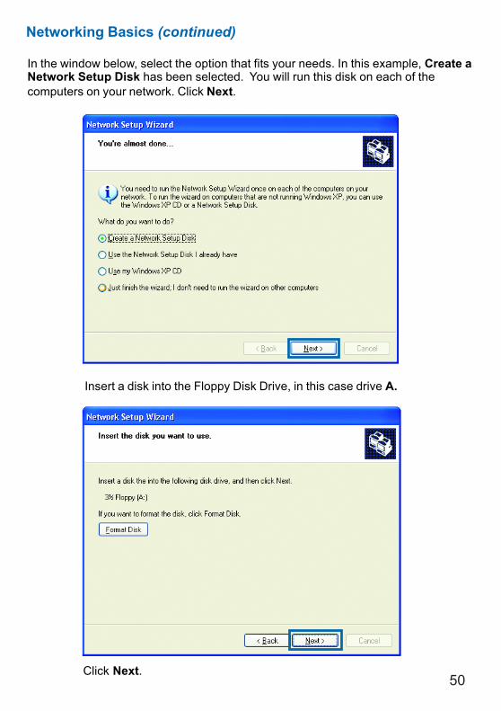
In the window below, select the option that fits your needs. In this example, Create aNetwork Setup Disk has been selected. You will run this disk on each of thecomputers on your network. Click Next.
Insert a disk into the Floppy Disk Drive, in this case drive A.
Click Next.
Networking Basics (continued)
51
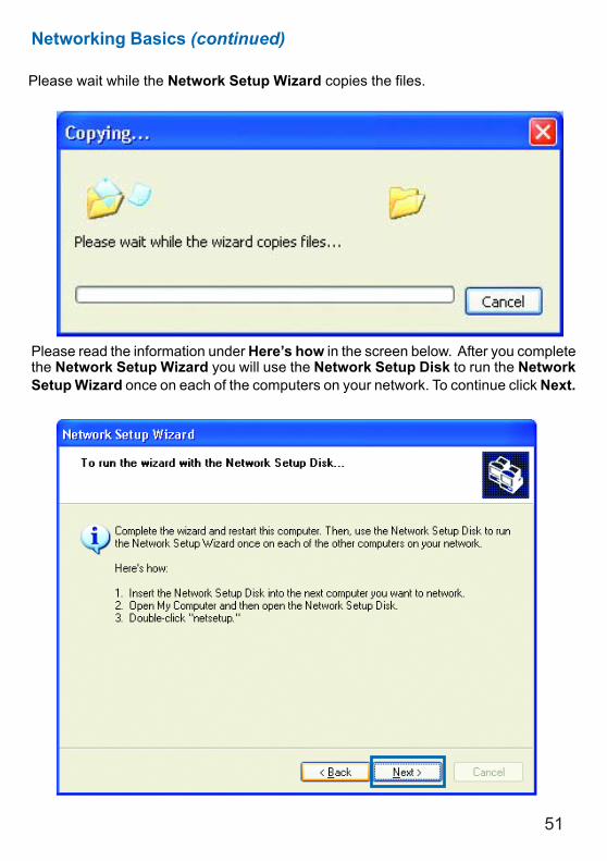
Please read the information under Here’s how in the screen below. After you completethe Network Setup Wizard you will use the Network Setup Disk to run the NetworkSetup Wizard once on each of the computers on your network. To continue click Next.
Networking Basics (continued)
Please wait while the Network Setup Wizard copies the files.
52
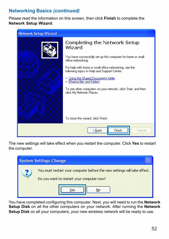
Please read the information on this screen, then click Finish to complete theNetwork Setup Wizard.
The new settings will take effect when you restart the computer. Click Yes to restartthe computer.
You have completed configuring this computer. Next, you will need to run the NetworkSetup Disk on all the other computers on your network. After running the NetworkSetup Disk on all your computers, your new wireless network will be ready to use.
Networking Basics (continued)
53
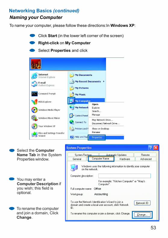
Naming your ComputerTo name your computer, please follow these directions:In Windows XP:
Click Start (in the lower left corner of the screen)
Right-click on My Computer
Select Properties and click
Select the ComputerName Tab in the SystemProperties window.
You may enter aComputer Description ifyou wish; this field isoptional.
To rename the computerand join a domain, ClickChange.
Networking Basics (continued)
54
Naming your Computer
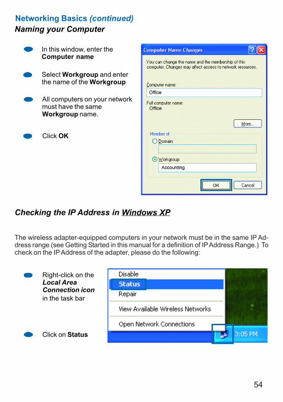
In this window, enter theComputer name
Select Workgroup and enterthe name of the Workgroup
All computers on your networkmust have the sameWorkgroup name.
Click OK
Checking the IP Address in Windows XP
The wireless adapter-equipped computers in your network must be in the same IP Ad-dress range (see Getting Started in this manual for a definition of IP Address Range.) Tocheck on the IP Address of the adapter, please do the following:
Right-click on theLocal AreaConnection iconin the task bar
Click on Status
Networking Basics (continued)
55
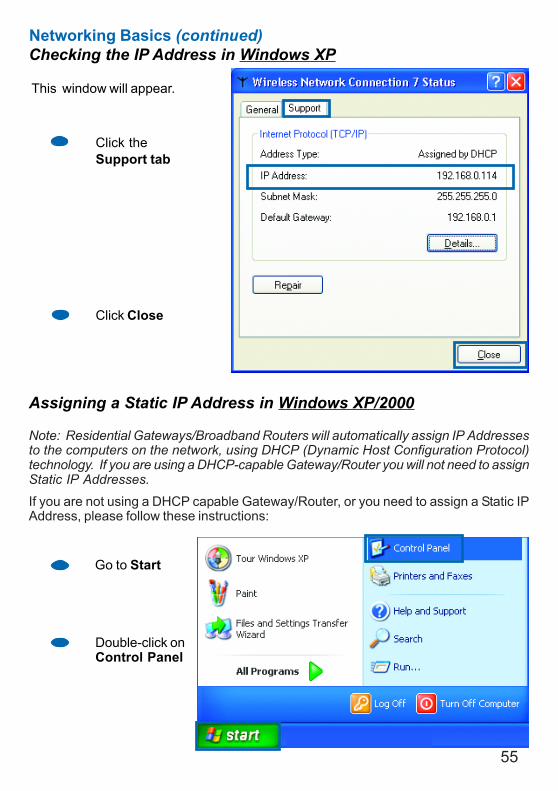
Checking the IP Address in Windows XP
This window will appear.
Click theSupport tab
Click Close
Assigning a Static IP Address in Windows XP/2000
Note: Residential Gateways/Broadband Routers will automatically assign IP Addressesto the computers on the network, using DHCP (Dynamic Host Configuration Protocol)technology. If you are using a DHCP-capable Gateway/Router you will not need to assignStatic IP Addresses.
If you are not using a DHCP capable Gateway/Router, or you need to assign a Static IPAddress, please follow these instructions:
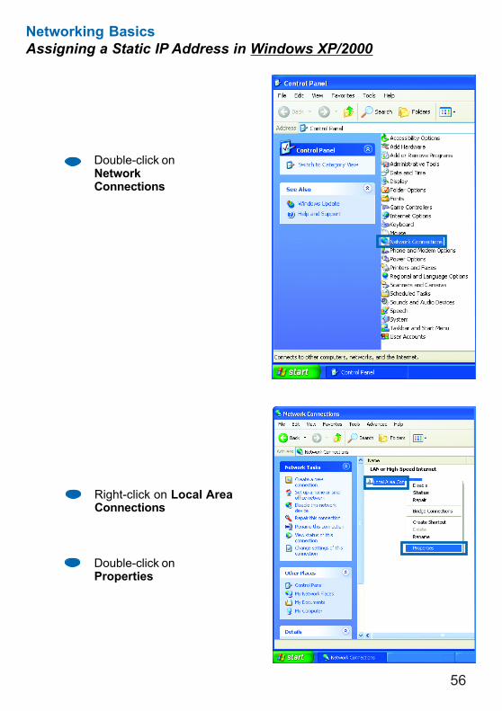
Go to Start
Double-click onControl Panel
Networking Basics (continued)
56
Networking BasicsAssigning a Static IP Address in Windows XP/2000
Double-click onNetworkConnections
Double-click onProperties
Right-click on Local AreaConnections
57
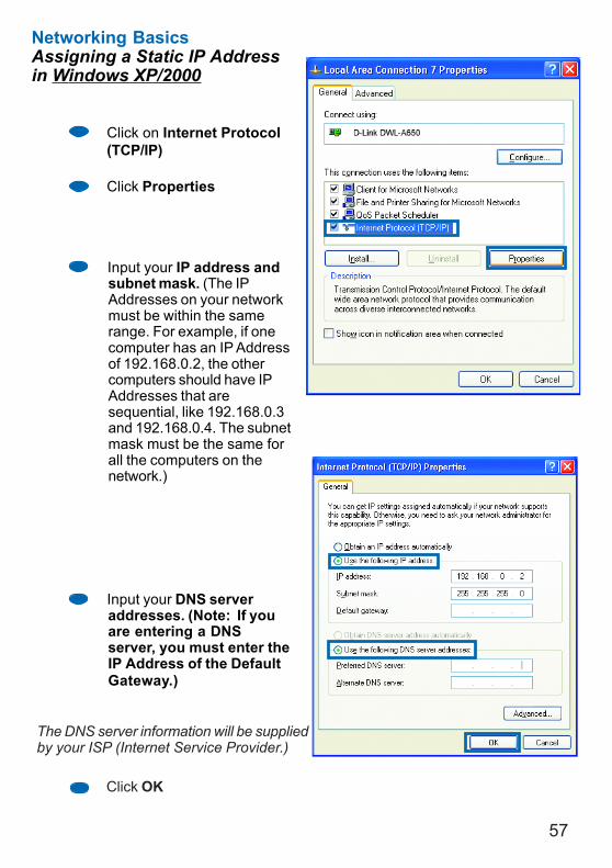
Input your IP address andsubnet mask. (The IPAddresses on your networkmust be within the samerange. For example, if onecomputer has an IP Addressof 192.168.0.2, the othercomputers should have IPAddresses that aresequential, like 192.168.0.3and 192.168.0.4. The subnetmask must be the same forall the computers on thenetwork.)
Networking BasicsAssigning a Static IP Addressin Windows XP/2000
Input your DNS serveraddresses. (Note: If youare entering a DNSserver, you must enter theIP Address of the DefaultGateway.)
The DNS server information will be suppliedby your ISP (Internet Service Provider.)
Click OK
Click on Internet Protocol(TCP/IP)
Click Properties
58
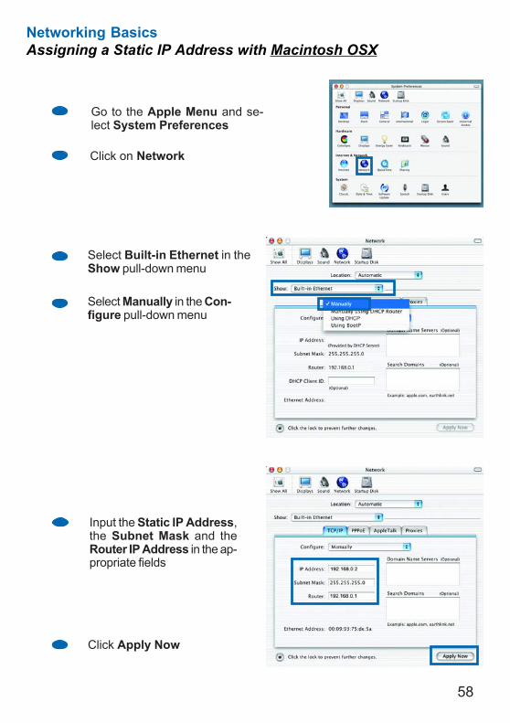
Networking BasicsAssigning a Static IP Address with Macintosh OSX
Go to the Apple Menu and se-lect System Preferences
cClick on Network
Select Built-in Ethernet in theShow pull-down menu
Select Manually in the Con-figure pull-down menu
Input the Static IP Address,the Subnet Mask and theRouter IP Address in the ap-propriate fields
Click Apply Now
59
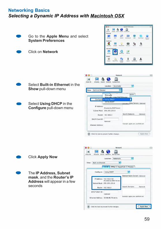
Networking BasicsSelecting a Dynamic IP Address with Macintosh OSX
Go to the Apple Menu and selectSystem Preferences
Click on Network
Select Built-in Ethernet in theShow pull-down menu
Select Using DHCP in theConfigure pull-down menu
Click Apply Now
The IP Address, Subnetmask, and the Router’s IPAddress will appear in a fewseconds
60
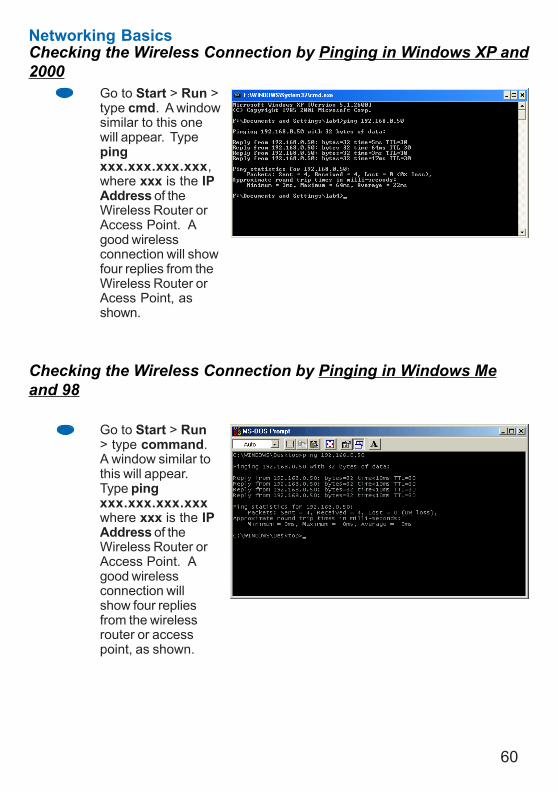
Networking BasicsChecking the Wireless Connection by Pinging in Windows XP and2000
Checking the Wireless Connection by Pinging in Windows Meand 98
Go to Start > Run >type cmd. A windowsimilar to this onewill appear. Typepingxxx.xxx.xxx.xxx,where xxx is the IPAddress of theWireless Router orAccess Point. Agood wirelessconnection will showfour replies from theWireless Router orAcess Point, asshown.
Go to Start > Run> type command.A window similar tothis will appear.Type pingxxx.xxx.xxx.xxxwhere xxx is the IPAddress of theWireless Router orAccess Point. Agood wirelessconnection willshow four repliesfrom the wirelessrouter or accesspoint, as shown.
61
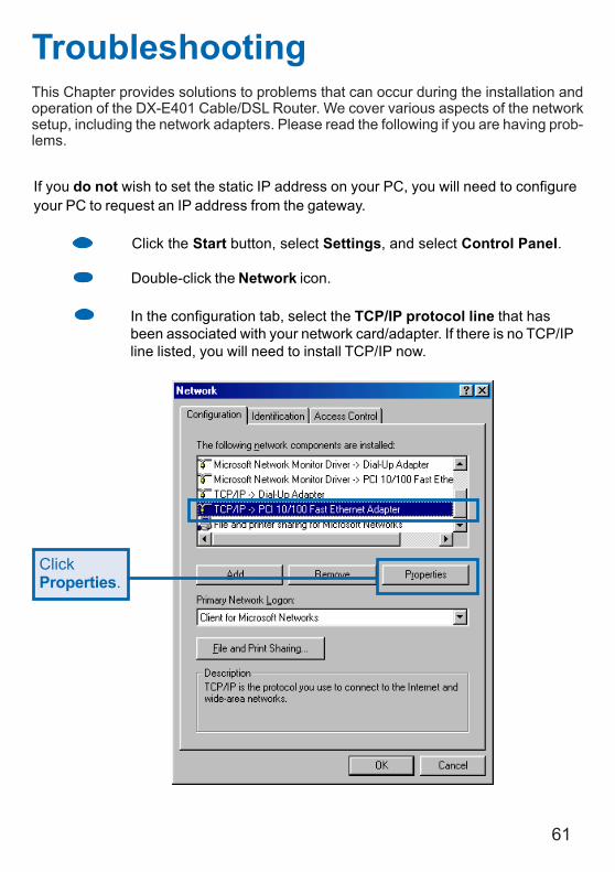
TroubleshootingThis Chapter provides solutions to problems that can occur during the installation andoperation of the DX-E401 Cable/DSL Router. We cover various aspects of the networksetup, including the network adapters. Please read the following if you are having prob-lems.
If you do not wish to set the static IP address on your PC, you will need to configureyour PC to request an IP address from the gateway.
Click the Start button, select Settings, and select Control Panel.
Double-click the Network icon.
In the configuration tab, select the TCP/IP protocol line that hasbeen associated with your network card/adapter. If there is no TCP/IPline listed, you will need to install TCP/IP now.
ClickProperties.
62
Troubleshooting (continued)
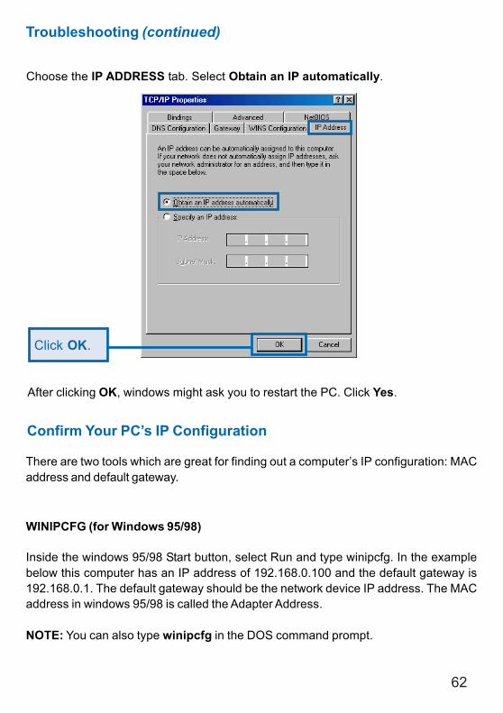
Choose the IP ADDRESS tab. Select Obtain an IP automatically.
After clicking OK, windows might ask you to restart the PC. Click Yes.
Click OK.
Confirm Your PC’s IP Configuration
There are two tools which are great for finding out a computer’s IP configuration: MACaddress and default gateway.
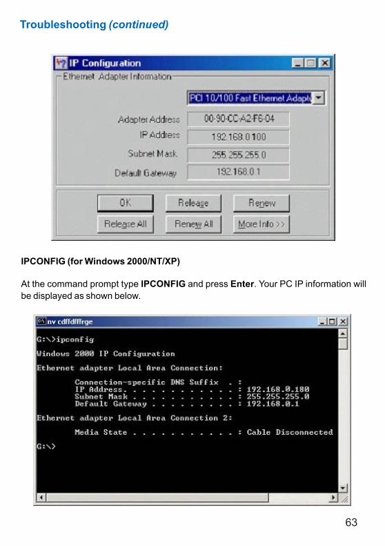
WINIPCFG (for Windows 95/98)
Inside the windows 95/98 Start button, select Run and type winipcfg. In the examplebelow this computer has an IP address of 192.168.0.100 and the default gateway is192.168.0.1. The default gateway should be the network device IP address. The MACaddress in windows 95/98 is called the Adapter Address.
NOTE: You can also type winipcfg in the DOS command prompt.
63
Troubleshooting (continued)
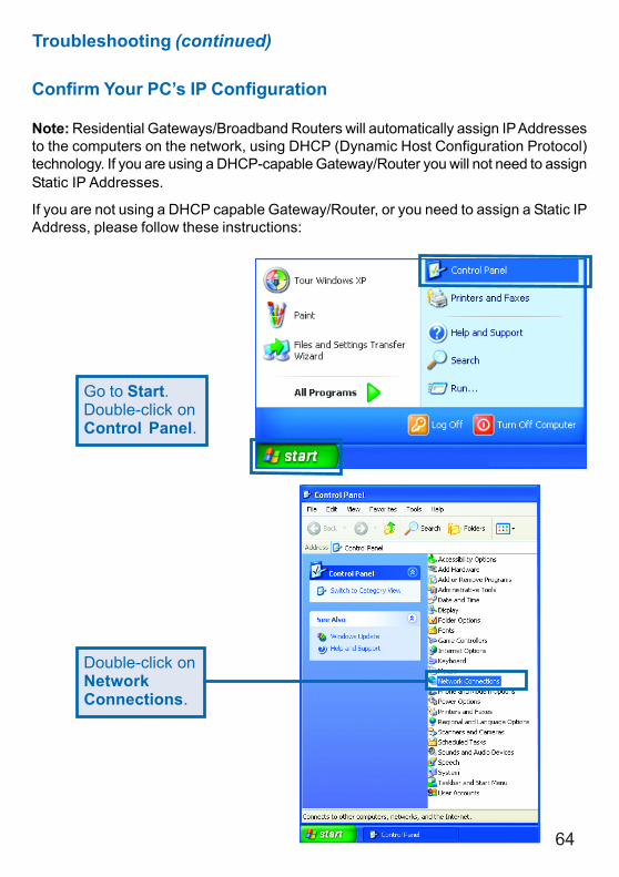
IPCONFIG (for Windows 2000/NT/XP)
At the command prompt type IPCONFIG and press Enter. Your PC IP information willbe displayed as shown below.
64
Troubleshooting (continued)
Confirm Your PC’s IP Configuration
Note: Residential Gateways/Broadband Routers will automatically assign IP Addressesto the computers on the network, using DHCP (Dynamic Host Configuration Protocol)technology. If you are using a DHCP-capable Gateway/Router you will not need to assignStatic IP Addresses.
If you are not using a DHCP capable Gateway/Router, or you need to assign a Static IPAddress, please follow these instructions:
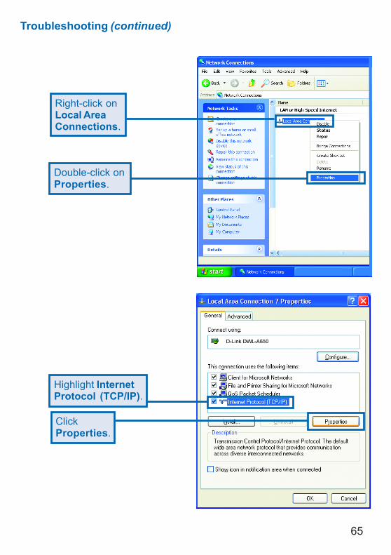
Go to Start.Double-click onControl Panel.
Double-click onNetworkConnections.
65
Troubleshooting (continued)
Double-click onProperties.
Right-click onLocal AreaConnections.
Highlight InternetProtocol (TCP/IP).
ClickProperties.
66
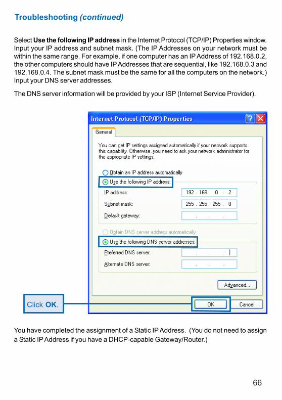
Troubleshooting (continued)
Select Use the following IP address in the Internet Protocol (TCP/IP) Properties window.Input your IP address and subnet mask. (The IP Addresses on your network must bewithin the same range. For example, if one computer has an IP Address of 192.168.0.2,the other computers should have IP Addresses that are sequential, like 192.168.0.3 and192.168.0.4. The subnet mask must be the same for all the computers on the network.)Input your DNS server addresses.
The DNS server information will be provided by your ISP (Internet Service Provider).
You have completed the assignment of a Static IP Address. (You do not need to assigna Static IP Address if you have a DHCP-capable Gateway/Router.)
Click OK.
67
IEEE 802.3u 100Base-TX Fast EthernetIEEE 802.3 Auto Negotiation
Technical Specifications
L2TP
Standards
VPN Pass Through/ Multi-Sessions
Device ManagementWeb-Based- Internet Explorer v6 or later; Netscape Navigator v6or later; or other Java-enabled browsers
Media Access Control
95% maximum (non-condensing)
Operating Temperature 32ºF to 131ºF (0ºC to 55ºC)
Humidity
IPSec
Safety and Emissions
IEEE 802.3 10Base-T Ethernet
PPTP
CMSA/CA with ACK
LEDsPowerWANLAN (10/100)
FCCUL
68
Physical DimensionsL = 5.51 inches (140mm)
Technical Specifications (continued)
W = 4.37 inches (111mm)H = 1.10inches (28mm)
Power Input
External Power SupplyDC 5V, 2.0A
Weight10.8 oz. (0.3kg)
Warranty
1 Year
69
You can find software updates and user documentation on the Dynex website.
Dynex provides free technical support for customers within the United States for theduration of the warranty period on this product.
U.S. customers can contact Dynex technical support through our web site, or byphone.
Tech Support for customers within the United States:Dynex Technical Support over the Telephone:(800) 305-220424 hours a day, seven days a week.
Dynex Technical Support over the Internet:http://www.dynexproducts.com
When contacting technical support, please provide the following information:
• Serial number of the unit
• Model number or product name
• Software type and version number
Technical Support
70
Warranty and Registration(USA only)
Subject to the terms and conditions set forth herein, Dynex provides this Limited warranty for its productonly to the person or entity that originally purchased the product from:
• Dynex or its authorized reseller or distributor and• Products purchased and delivered within the fifty states of the United States, the District of Columbia,
U.S. Possessions or Protectorates, U.S. Military Installations, addresses with an APO or FPO.
Limited Warranty: Dynex warrants that the hardware portion of the Dynex products describedbelow will be free from material defects in workmanship and materials from the date of original retailpurchase of the product, for the period set forth below applicable to the product type (“WarrantyPeriod”), except as otherwise stated herein.
1-Year Limited Warranty for the Product(s) is defined as follows:
• Hardware (excluding power supplies and fans) One (1) Year• Power Supplies and Fans One (1) Year• Spare parts and spare kits Ninety (90) days
Dynex’s sole obligation shall be to repair or replace the defective Hardware during the Warranty Periodat no charge to the original owner or to refund at Dynex’s sole discretion. The replacement Hardwareneed not be new or have an identical make, model or part. Dynex may in its sole discretion replace thedefective Hardware (or any part thereof) with any reconditioned product that Dynex reasonablydetermines is substantially equivalent (or superior) in all material respects to the defective Hardware.Repaired or replacement Hardware will be warranted for the remainder of the original Warranty Periodfrom the date of original retail purchase. If a material defect is incapable of correction, or if Dynexdetermines in its sole discretion that it is not practical to repair or replace the defective Hardware, theprice paid by the original purchaser for the defective Hardware will be refunded by Dynex upon returnto Dynex of the defective Hardware. All Hardware (or part thereof) that is replaced by Dynex, or forwhich the purchase price is refunded, shall become the property of Dynex upon replacement or refund.
Limited Software Warranty: Dynex warrants that the software portion of the product (“Software”)will substantially conform to Dynex’s then current functional specifications for the Software, as set forthin the applicable documentation, from the date of original retail purchase of the Software for a period ofninety (90) days (“Warranty Period”), provided that the Software is properly installed on approvedhardware and operated as contemplated in its documentation. Dynex further warrants that, during theWarranty Period, the magnetic media on which Dynex delivers the Software will be free of physicaldefects. Dynex’s sole obligation shall be to replace the non-conforming Software (or defective media)with software that substantially conforms to Dynex’s functional specifications for the Software or torefund at Dynex’s sole discretion. Except as otherwise agreed by Dynex in writing, the replacementSoftware is provided only to the original licensee, and is subject to the terms and conditions of thelicense granted by Dynex for the Software. Software will be warranted for the remainder of the originalWarranty Period from the date or original retail purchase. If a material non-conformance is incapable ofcorrection, or if Dynex determines in its sole discretion that it is not practical to replace the non-conforming Software, the price paid by the original licensee for the non-conforming Software will berefunded by Dynex; provided that the non-conforming Software (and all copies thereof) is first returnedto Dynex. The license granted respecting any Software for which a refund is given automaticallyterminates.
71
Non-Applicability of Warranty: The Limited Warranty provided hereunder for hardware and softwareof Dynex’s products will not be applied to and does not cover any refurbished product and any productpurchased through the inventory clearance or liquidation sale or other sales in which Dynex, the sellers,or the liquidators expressly disclaim their warranty obligation pertaining to the product and in that case,the product is being sold “As-Is” without any warranty whatsoever including, without limitation, theLimited Warranty as described herein, notwithstanding anything stated herein to the contrary.
What Is Not Covered: This limited warranty provided by Dynex does not cover: Products, if in Dynex’sjudgment, have been subjected to abuse, accident, alteration, modification, tampering, negligence, misuse,faulty installation, lack of reasonable care, repair or service in any way that is not contemplated in thedocumentation for the product, or if the model or serial number has been altered, tampered with, defacedor removed; Initial installation, installation and removal of the product for repair, and shipping costs;Operational adjustments covered in the operating manual for the product, and normal maintenance;Damage that occurs in shipment, due to act of God, failures due to power surge, and cosmetic damage;Any hardware, software, firmware or other products or services provided by anyone other thanDynex; Products that have been purchased from inventory clearance or liquidation sales or other salesin which Dynex, the sellers, or the liquidators expressly disclaim their warranty obligation pertaining tothe product. Repair by anyone other than Dynex or an Authorized Dynex Service Office will void thisWarranty.
Disclaimer of Other Warranties: EXCEPT FOR THE LIMITED WARRANTY SPECIFIED HEREIN, THEPRODUCT IS PROVIDED “AS-IS” WITHOUT ANY WARRANTY OF ANY KIND WHATSOEVER INCLUDING,WITHOUT LIMITATION, ANY WARRANTY OF MERCHANTABILITY, FITNESS FOR A PARTICULAR PURPOSEAND NON-INFRINGEMENT. IF ANY IMPLIED WARRANTY CANNOT BE DISCLAIMED IN ANY TERRITORYWHERE A PRODUCT IS SOLD, THE DURATION OF SUCH IMPLIED WARRANTY SHALL BE LIMITED TONINETY (90) DAYS. EXCEPT AS EXPRESSLY COVERED UNDER THE LIMITED WARRANTY PROVIDEDHEREIN, THE ENTIRE RISK AS TO THE QUALITY, SELECTION AND PERFORMANCE OF THE PRODUCT ISWITH THE PURCHASER OF THE PRODUCT.
Submitting A Claim: The customer shall return the product to the original purchase point based on itsreturn policy. In case the return policy period has expired and the product is within warranty, thecustomer shall submit a claim to Dynex as outlined below:
• The customer must submit with the product as part of the claim a written description of theHardware defect or Software nonconformance in sufficient detail to allow Dynex to confirm thesame.
• The original product owner must obtain a Return Material Authorization (“RMA”) number fromthe Authorized Dynex Service Office and, if requested, provide written proof of purchase of theproduct (such as a copy of the dated purchase invoice for the product) before the warrantyservice is provided.
• After an RMA number is issued, the defective product must be packaged securely in theoriginal or other suitable shipping package to ensure that it will not be damaged in transit, and theRMA number must be prominently marked on the outside of the package. Do not include any manualsor accessories in the shipping package. Dynex will only replace the defective portion of the Productand will not ship back any accessories.
• The customer is responsible for all in-bound shipping charges to Dynex. No Cash on Delivery(“COD”) is allowed. Products sent COD will either be rejected by Dynex or become the property ofDynex. Products shall be fully insured by the customer and shipped to Dynex Products ReturnCenter, 901 East Northfield Drive, Brownsburg, IN 46112. Dynex will not be held responsiblefor any packages that are lost in transit to Dynex. The repaired or replaced packages will beshipped to the customer via UPS Ground or any common carrier selected by Dynex, with shippingcharges prepaid. Expedited shipping is available if shipping charges are prepaid by the customerand upon request.
Dynex may reject or return any product that is not packaged and shipped in strict compliance with theforegoing requirements, or for which an RMA number is not visible from the outside of the package. Theproduct owner agrees to pay Dynex’s reasonable handling and return shipping charges for any productthat is not packaged and shipped in accordance with the foregoing requirements, or that is determinedby Dynex not to be defective or non-conforming.
72 (01/12/2004)
Governing Law: This Limited Warranty shall be governed by the laws of the State of California. Somestates do not allow exclusion or limitation of incidental or consequential damages, or limitations on howlong an implied warranty lasts, so the foregoing limitations and exclusions may not apply. This limitedwarranty provides specific legal rights and the product owner may also have other rights which varyfrom state to state.Trademarks: Dynex is a registered trademark of Dynex. Other trademarks or registered trademarksare the property of their respective manufacturers or owners.Copyright Statement: No part of this publication or documentation accompanying this Product may bereproduced in any form or by any means or used to make any derivative such as translation, transformation,or adaptation without permission from Dynex, as stipulated by the United States Copyright Act of 1976.Contents are subject to change without prior notice. Copyright© 2004by Dynex. All rights reserved.CE Mark Warning: This is a Class B product. In a domestic environment, this product may cause radiointerference, in which case the user may be required to take adequate measures.FCC Statement: This equipment has been tested and found to comply with the limits for a Class B digitaldevice, pursuant to part 15 of the FCC Rules. These limits are designed to provide reasonable protectionagainst harmful interference in a residential installation. This equipment generates, uses, and can radiateradio frequency energy and, if not installed and used in accordance with the instructions, may causeharmful interference to radio communication. However, there is no guarantee that interference will notoccur in a particular installation. If this equipment does cause harmful interference to radio or televisionreception, which can be determined by turning the equipment off and on, the user is encouraged to tryto correct the interference by one or more of the following measures:• Reorient or relocate the receiving antenna.• Increase the separation between the equipment and receiver.• Connect the equipment into an outlet on a circuit different from that to which the receiver is
connected.• Consult the dealer or an experienced radio/TV technician for help.
01/13/04
Limitation of Liability: TO THE MAXIMUM EXTENT PERMITTED BY LAW, DYNEX IS NOT LIABLEUNDER ANY CONTRACT, NEGLIGENCE, STRICT LIABILITY OR OTHER LEGAL OR EQUITABLE THEORYFOR ANY LOSS OF USE OF THE PRODUCT, INCONVENIENCE OR DAMAGES OF ANY CHARACTER,WHETHER DIRECT, SPECIAL, INCIDENTAL OR CONSEQUENTIAL (INCLUDING, BUT NOT LIMITED TO,DAMAGES FOR LOSS OF GOODWILL, LOSS OF REVENUE OR PROFIT, WORK STOPPAGE, COMPUTERFAILURE OR MALFUNCTION, FAILURE OF OTHER EQUIPMENT OR COMPUTER PROGRAMS TO WHICHDYNEX’S PRODUCT IS CONNECTED WITH, LOSS OF INFORMATION OR DATA CONTAINED IN, STOREDON, OR INTEGRATED WITH ANY PRODUCT RETURNED TO DYNEX FOR WARRANTY SERVICE) RESULTINGFROM THE USE OF THE PRODUCT, RELATING TO WARRANTY SERVICE, OR ARISING OUT OF ANYBREACH OF THIS LIMITED WARRANTY, EVEN IF DYNEX HAS BEEN ADVISED OF THE POSSIBILITY OFSUCH DAMAGES. THE SOLE REMEDY FOR A BREACH OF THE FOREGOING LIMITED WARRANTY ISREPAIR, REPLACEMENT OR REFUND OF THE DEFECTIVE OR NON-CONFORMING PRODUCT. THE MAXIMUMLIABILITY OF DYNEX UNDER THIS WARRANTY IS LIMITED TO THE PURCHASE PRICE OF THE PRODUCTCOVERED BY THE WARRANTY. THE FOREGOING EXPRESS WRITTEN WARRANTIES AND REMEDIESARE EXCLUSIVE AND ARE IN LIEU OF ANY OTHER WARRANTIES OR REMEDIES, EXPRESS, IMPLIED ORSTATUTORY