Embed Size (px)
Citation preview
DX-120 ION CHROMATOGRAPHOPERATOR’S MANUAL
© 1998 Dionex Corporation
Document No. 031183Revision 03
September 1998

©1998 by Dionex CorporationAll rights reserved worldwide.Printed in the United States of America.
This publication is protected by federal copyright law. No part of this publicationmay be copied or distributed, transmitted, transcribed, stored in a retrieval system,or transmitted into any human or computer language, in any form or by any means,electronic, mechanical, magnetic, manual, or otherwise, or disclosed to third partieswithout the express written permission of Dionex Corporation, 1228 Titan Way,Sunnyvale, California 94088-3603 U.S.A.
DISCLAIMER OF WARRANTY AND LIMITED WARRANTY
THIS PUBLICATION IS PROVIDED “AS IS” WITHOUT WARRANTY OFANY KIND. DIONEX CORPORATION DOES NOT WARRANT,GUARANTEE, OR MAKE ANY EXPRESS OR IMPLIEDREPRESENTATIONS REGARDING THE USE, OR THE RESULTS OF THEUSE, OF THIS PUBLICATION IN TERMS OF CORRECTNESS,ACCURACY, RELIABILITY, CURRENTNESS, OR OTHERWISE.FURTHER, DIONEX CORPORATION RESERVES THE RIGHT TO REVISETHIS PUBLICATION AND TO MAKE CHANGES FROM TIME TO TIMEIN THE CONTENT HEREINOF WITHOUT OBLIGATION OF DIONEXCORPORATION TO NOTIFY ANY PERSON OR ORGANIZATION OFSUCH REVISION OR CHANGES.
EMISSIONS COMPLIANCE
This equipment meets ITE standard EN 55022 part A for radiated emissions and issuitable for use in a laboratory environment. Operation of this equipment in aresidential area, however, may cause interference to radio and television reception.
TRADEMARKS
Teflon® and Tefzel® are registered trademarks of E.I. duPont de Nemours & Co.AutoSuppression , DX-LAN , IonSep®, MPIC®, OmniPac®, OnGuard ,Self-Regenerating Suppressor , and SRS are trademarks of Dionex Corp.
PRINTING HISTORY
Revision 01, May 1996Revision 02, March 1997Revision 03, September 1998
Contents
1 • Introduction
1.1 About This Manual . . . . . . . . . . . . . . . . . 1-2
1.1.1 Typefaces and Conventions . . . . . . . . 1-3
1.1.2 Safety Messages and Notes . . . . . . . . 1-4
1.1.3 Symbols . . . . . . . . . . . . . . . . . . . 1-5
1.2 Related Manuals . . . . . . . . . . . . . . . . . . . 1-5
2 • Description
2.1 Operating Features . . . . . . . . . . . . . . . . . 2-1
2.1.1 Front Control Panel . . . . . . . . . . . . 2-3
2.1.2 Pump . . . . . . . . . . . . . . . . . . . . 2-6
2.1.3 Configuration DIP Switches . . . . . . . 2-6
2.1.4 Eluent Reservoirs . . . . . . . . . . . . . 2-7
2.1.5 Component Panel . . . . . . . . . . . . . 2-8
2.1.6 Rheodyne Injection Valve . . . . . . . . . 2-11
2.1.7 Detector Cells . . . . . . . . . . . . . . . 2-12
2.1.8 DS4 Detection Stabilizer . . . . . . . . . 2-13
2.2 Dual-Column Configuration Features . . . . . . . 2-15
2.2.1 Column Select Mode . . . . . . . . . . . 2-16
2.2.2 Eluent Select Mode . . . . . . . . . . . . 2-18
2.3 Fluid Schematics . . . . . . . . . . . . . . . . . . 2-19
2.4 Control Modes . . . . . . . . . . . . . . . . . . . . 2-22
2.4.1 Local Mode . . . . . . . . . . . . . . . . . 2-22
2.4.2 Remote Mode . . . . . . . . . . . . . . . 2-22
Doc. 031138-03 9/98 i
2.5 TTL Control . . . . . . . . . . . . . . . . . . . . . 2-23
2.5.1 Injection Valve/Remote Start Control . . 2-23
2.5.2 Recorder Range Control . . . . . . . . . . 2-23
3 • Operation and Maintenance
3.1 Preparing Eluents . . . . . . . . . . . . . . . . . . 3-1
3.1.1 Degassing Eluents . . . . . . . . . . . . . 3-1
3.1.2 Filtering Eluents . . . . . . . . . . . . . . 3-2
3.1.3 Pressurizing Eluent Reservoirs . . . . . . 3-2
3.2 Preparing Samples . . . . . . . . . . . . . . . . . 3-3
3.2.1 Collecting and Storing . . . . . . . . . . . 3-3
3.2.2 Pretreating . . . . . . . . . . . . . . . . . 3-3
3.2.3 Diluting . . . . . . . . . . . . . . . . . . . 3-4
3.3 Operating . . . . . . . . . . . . . . . . . . . . . . 3-5
3.3.1 Starting Up . . . . . . . . . . . . . . . . . 3-5
3.3.2 Injecting the Sample . . . . . . . . . . . . 3-7
3.4 Using an Integrator . . . . . . . . . . . . . . . . . 3-9
3.5 Running under PeakNet Control . . . . . . . . . . 3-9
3.6 Optimizing Temperature Compensation . . . . . . 3-10
3.6.1 With a DS4 . . . . . . . . . . . . . . . . . 3-10
3.6.2 With a CDM-3 Cell . . . . . . . . . . . . 3-10
3.7 Maintenance . . . . . . . . . . . . . . . . . . . . . 3-11
4 • Troubleshooting
4.1 Alarms . . . . . . . . . . . . . . . . . . . . . . . . 4-1
4.2 Error Codes . . . . . . . . . . . . . . . . . . . . . 4-3
4.3 Liquid Leaks . . . . . . . . . . . . . . . . . . . . . 4-4
4.4 Pump Difficult to Prime . . . . . . . . . . . . . . 4-8
DX-120 Operator’s Manual
ii Doc. 031138-03 9/98

4.5 Pump Loses Prime . . . . . . . . . . . . . . . . . 4-8
4.6 Pump Does Not Start . . . . . . . . . . . . . . . . 4-9
4.7 No Flow . . . . . . . . . . . . . . . . . . . . . . . 4-9
4.8 Excessive System Backpressure . . . . . . . . . . 4-9
4.9 Peak “Ghosting” . . . . . . . . . . . . . . . . . . . 4-10
4.10 Nonreproducible Peak Height or RetentionTime . . . . . . . . . . . . . . . . . . . . . . . . . 4-11
4.11 Abnormal Retention Time or Selectivity . . . . . 4-11
4.12 DS4 Temperature Inaccurate . . . . . . . . . . . . 4-12
4.13 No Detector Response . . . . . . . . . . . . . . . 4-13
4.14 Low Detector Output . . . . . . . . . . . . . . . . 4-14
4.15 High Detector Output . . . . . . . . . . . . . . . . 4-14
4.16 Noisy or Drifting Baseline . . . . . . . . . . . . . 4-15
5 • Service
5.1 Replacing Tubing and Fittings . . . . . . . . . . . 5-2
5.2 Changing the Sample Loop . . . . . . . . . . . . 5-2
5.3 Isolating a Restriction in the Liquid Plumbing . . 5-3
5.4 Replacing the DS4 Cell . . . . . . . . . . . . . . . 5-3
5.5 Cleaning Cell Electrodes . . . . . . . . . . . . . . 5-5
5.6 Calibrating the Cell Constant . . . . . . . . . . . 5-6
5.7 Calibrating the Pump Flow Rate . . . . . . . . . . 5-8
5.8 Cleaning and Replacing Pump Check Valves . . . 5-8
5.9 Replacing a Pump Piston Seal . . . . . . . . . . . 5-9
5.10 Replacing a Pump Piston . . . . . . . . . . . . . . 5-12
5.11 Replacing the Pressure Transducer WasteValve O-Ring . . . . . . . . . . . . . . . . . . . . 5-14
5.12 Changing the Main Power Fuses . . . . . . . . . . 5-15
Contents
Doc. 031138-03 9/98 iii
A • Specifications
A.1 Electrical . . . . . . . . . . . . . . . . . . . . . . . A-1
A.2 Environmental/Physical . . . . . . . . . . . . . . . A-1
A.3 Control Panel . . . . . . . . . . . . . . . . . . . . A-2
A.4 Pump . . . . . . . . . . . . . . . . . . . . . . . . . A-2
A.5 Pulse Damper . . . . . . . . . . . . . . . . . . . . A-2
A.6 Detector . . . . . . . . . . . . . . . . . . . . . . . A-2
A.7 Conductivity Cell . . . . . . . . . . . . . . . . . . A-3
A.8 DS4 Detection Stabilizer (Optional) . . . . . . . . A-3
A.9 Valves . . . . . . . . . . . . . . . . . . . . . . . . A-3
A.10 Delay Volume . . . . . . . . . . . . . . . . . . . . A-4
B • Installation
B.1 Facility Requirements . . . . . . . . . . . . . . . . B-1
B.2 Installation Overview . . . . . . . . . . . . . . . B-1
B.3 Rear Panel Connections . . . . . . . . . . . . . . B-2
B.3.1 Power Connection . . . . . . . . . . . . . B-2
B.3.2 Switched AC Outlet Connection(Optional) . . . . . . . . . . . . . . . . . . B-4
B.3.3 Waste Lines . . . . . . . . . . . . . . . . . B-5
B.3.4 Gas Connection . . . . . . . . . . . . . . B-5
B.3.5 DX-LAN Cable Connection (Optional) . B-6
B.4 Eluent Reservoir Connections . . . . . . . . . . . B-8
B.5 Pump Setup . . . . . . . . . . . . . . . . . . . . . B-8
B.5.1 Priming the Pump . . . . . . . . . . . . . B-8
B.5.2 Checking the Pump Flow RateCalibration . . . . . . . . . . . . . . . . . B-9
DX-120 Operator’s Manual
iv Doc. 031138-03 9/98
B.6 Connections to Chromatography Components . . B-10
B.6.1 Backpressure Requirements . . . . . . . . B-12
B.6.2 Self-Regenerating Suppressor (SRS)Installation . . . . . . . . . . . . . . . . . B-13
B.6.3 Column Installation . . . . . . . . . . . . B-17
B.7 TTL Control Connections (Overview) . . . . . . . B-19
B.7.1 TTL Inputs . . . . . . . . . . . . . . . . . B-19
B.7.2 TTL Outputs . . . . . . . . . . . . . . . . B-20
B.7.3 Ferrite Core Installation on TTL OutputCables . . . . . . . . . . . . . . . . . . . . B-21
B.8 Autosampler Connections (Optional) . . . . . . . B-22
B.8.1 Autosampler Outlet Line Connection . . B-22
B.8.2 AS40 Automated Sampler Connections . B-22
B.8.3 AS3500 Automated Sampler Connections . . . . . . . . . . . . . . . . B-24
B.9 Recorder and Integrator Connections (Optional) . . . . . . . . . . . . . . . . . . . . . . B-27
B.9.1 Chart Recorder Connections . . . . . . . B-27
B.9.2 4400 or 4600 Integrator Connections . . B-27
B.10 Configuration DIP Switch Settings . . . . . . . . B-29
B.11 DS4 Detection Stabilizer Installation . . . . . . . B-33
B.12 CDM-3 Cell Installation . . . . . . . . . . . . . . B-35
B.13 Injection Valve Connections . . . . . . . . . . . . B-36
B.14 Column Switching Valve Connections . . . . . . . B-37
B.15 DX-LAN Card Installation (Optional) . . . . . . . B-38
C • Integrator Programming
C.1 Integrator Power-up Configuration . . . . . . . . C-1
C.2 Setting Offsets . . . . . . . . . . . . . . . . . . . . C-2
C.3 Area Percent Mode . . . . . . . . . . . . . . . . . C-2
Contents
Doc. 031138-03 9/98 v
C.4 Using DIALOG to Create a Method . . . . . . . . C-3
C.4.1 Time Functions . . . . . . . . . . . . . . . C-3
C.4.2 Creating a Method . . . . . . . . . . . . . C-4
C.5 BASIC Programming . . . . . . . . . . . . . . . . C-7
D • Conductivity Detection
D.1 How Conductivity Is Measured . . . . . . . . . . D-1
D.2 Conductivity of Solutions . . . . . . . . . . . . . D-2
D.2.1 Effect of Hydration Sphere and Solvent on Conductivity . . . . . . . . . . D-4
D.2.2 Effect of Temperature on Conductivity . D-4
D.2.3 Species Detected by Conductivity . . . . D-5
D.2.4 Chemical Suppression . . . . . . . . . . . D-6
D.2.5 Eluents for Conductivity Detection . . . D-9
E • Glossary
DX-120 Operator’s Manual
vi Doc. 031138-03 9/98
1 • Introduction
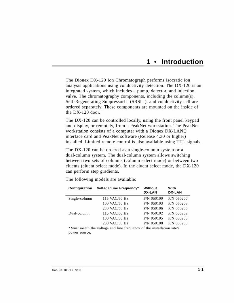
The Dionex DX-120 Ion Chromatograph performs isocratic ionanalysis applications using conductivity detection. The DX-120 is anintegrated system, which includes a pump, detector, and injectionvalve. The chromatography components, including the column(s),Self-Regenerating Suppressor (SRS ), and conductivity cell areordered separately. These components are mounted on the inside ofthe DX-120 door.
The DX-120 can be controlled locally, using the front panel keypadand display, or remotely, from a PeakNet workstation. The PeakNetworkstation consists of a computer with a Dionex DX-LANinterface card and PeakNet software (Release 4.30 or higher)installed. Limited remote control is also available using TTL signals.
The DX-120 can be ordered as a single-column system or adual-column system. The dual-column system allows switchingbetween two sets of columns (column select mode) or between twoeluents (eluent select mode). In the eluent select mode, the DX-120can perform step gradients.
The following models are available:
Configuration Voltage/Line Frequency* WithoutDX-LAN
With DX-LAN
Single-column 115 VAC/60 Hz P/N 050100 P/N 050200 100 VAC/50 Hz P/N 050103 P/N 050203 230 VAC/50 Hz P/N 050106 P/N 050206
Dual-column 115 VAC/60 Hz P/N 050102 P/N 050202 100 VAC/50 Hz P/N 050105 P/N 050205 230 VAC/50 Hz P/N 050108 P/N 050208
*Must match the voltage and line frequency of the installation site’spower source.
Doc. 031183-03 9/98 1-1
1.1 About This Manual
Chapter 1Introduction
Introduces the DX-120 and explains theconventions used in the manual, includingsafety-related information.
Chapter 2Description
Describes the DX-120 operating features, thechromatographic fluid path, and the controlmodes.
Chapter 3Operation and
Maintenance
Provides operating and routine preventivemaintenance procedures.
Chapter 4Troubleshooting
Lists problems, with step-by-step procedures toisolate and eliminate their sources.
Chapter 5Service
Provides step-by-step instructions for routineservice and parts replacement procedures.
Appendix ASpecifications
Lists the DX-120 specifications and installationsite requirements.
Appendix BInstallation
Describes how to install the DX-120.
Appendix CIntegrator
Programming
Describes how to program a Dionex 4400 or4600 integrator for automated control of theDX-120.
Appendix DConductivity
Detection
Describes conductivity detection and itsapplications.
Appendix EGlossary
Defines terms commonly used in ionchromatography.
DX-120 Operator’s Manual
1-2 Doc. 031183-03 9/98
1.1.1 Typefaces and Conventions
• Capitalized bold type indicates a front panel button. Forexample:
Press Pump to turn on the pump.
• Upper-case bold type indicates information displayed onthe front panel screen. For example:
LEAK ALARM displays when a leak occurs.
• Upper-case italic type indicates a grouping of front panelbuttons. For example:
Use the buttons in the DISPLAY group to select the typeof information shown on-screen.
• When a function can be controlled by a DIP switchsetting, the switch and position numbers are inparentheses. For example:
(SW1-3) indicates DIP switch 1, position 3.
(SW2-5, 6, 7, 8) indicates DIP switch 2, positions 5, 6, 7,and 8.
1 • Introduction
Doc. 031183-03 9/98 1-3
1.1.2 Safety Messages and Notes
The DX-120 meets European, EMC, and safety requirementsper Council Directives 73/23/EEC and 89/336/EEC, EN61010-1:1993 (safety), EN 50082-1:1992 (susceptibility), andEN 55011:1991 (emissions). The TUV/CE and GS safetylabel on the DX-120 attests to compliance with thesestandards.
The DX-120 is designed for ion chromatography applicationsand should not be used for any other purpose. If there is aquestion regarding appropriate usage, contact Dionex beforeproceeding.
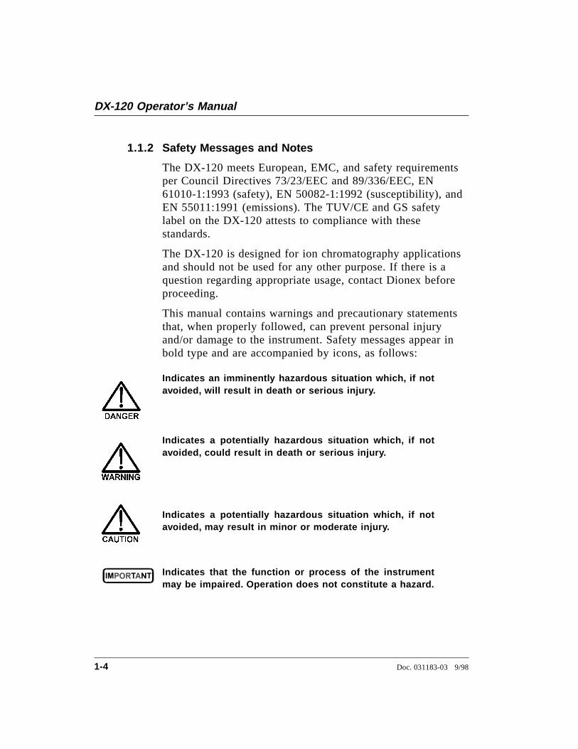
This manual contains warnings and precautionary statementsthat, when properly followed, can prevent personal injuryand/or damage to the instrument. Safety messages appear inbold type and are accompanied by icons, as follows:
Indicates an imminently hazardous situation which, if notavoided, will result in death or serious injury.
Indicates a potentially hazardous situation which, if notavoided, could result in death or serious injury.
Indicates a potentially hazardous situation which, if notavoided, may result in minor or moderate injury.
Indicates that the function or process of the instrumentmay be impaired. Operation does not constitute a hazard.
DX-120 Operator’s Manual
1-4 Doc. 031183-03 9/98
Informational messages also appear throughout this manual.These are labeled NOTE and are in bold type:
NOTENOTES call attention to certain information. They alertyou to an unexpected result of an action, suggest how tooptimize instrument performance, etc.
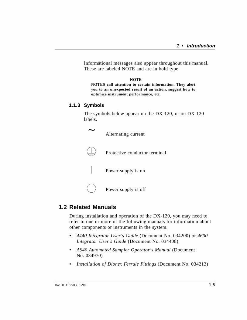
1.1.3 Symbols
The symbols below appear on the DX-120, or on DX-120labels.
Alternating current
Protective conductor terminal
Power supply is on
Power supply is off
1.2 Related ManualsDuring installation and operation of the DX-120, you may need torefer to one or more of the following manuals for information aboutother components or instruments in the system.
• 4440 Integrator User’s Guide (Document No. 034200) or 4600Integrator User’s Guide (Document No. 034408)
• AS40 Automated Sampler Operator’s Manual (DocumentNo. 034970)
• Installation of Dionex Ferrule Fittings (Document No. 034213)
~
1 • Introduction
Doc. 031183-03 9/98 1-5
• PeakNet Software User’s Guide (Document No. 034914)
• Installing the PeakNet System (Document No. 034941)
DX-120 Operator’s Manual
1-6 Doc. 031183-03 9/98
2 • Description
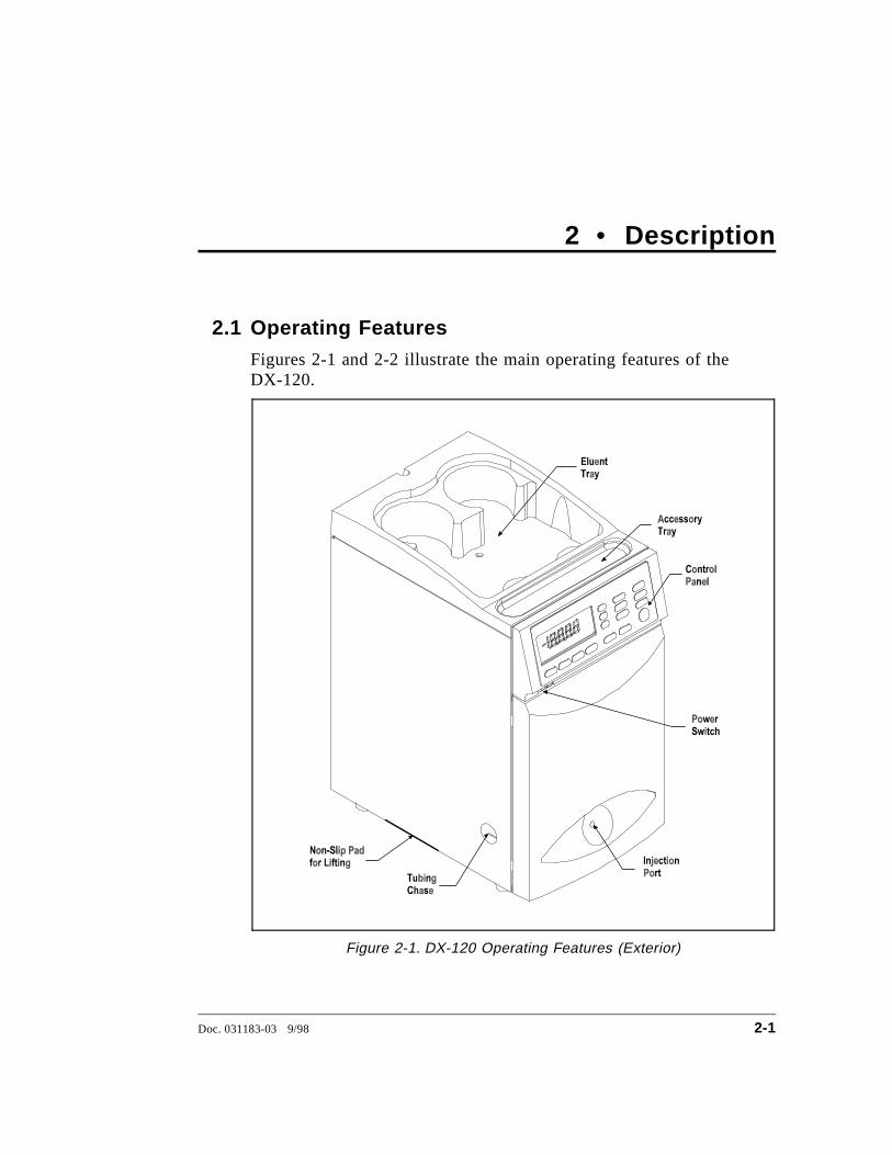
2.1 Operating FeaturesFigures 2-1 and 2-2 illustrate the main operating features of theDX-120.
Figure 2-1. DX-120 Operating Features (Exterior)
Doc. 031183-03 9/98 2-1
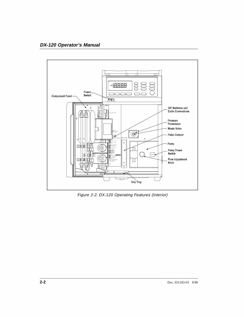
Figure 2-2. DX-120 Operating Features (Interior)
DX-120 Operator’s Manual
2-2 Doc. 031183-03 9/98

2.1.1 Front Control Panel
The control panel liquid crystal display (LCD) shows statusinformation and alarm conditions. Press a button in the grouplabeled DISPLAY to determine the type of status informationshown. The remaining buttons control DX-120 operation.
Button Function
DISPLAY
Displays the pump flow rate setting (0.5 to 4.5 mL/min).
Displays the pump pressure transducer reading (0 to27.6 MPa or 0 to 4000 psi)
NOTE MPa is the default pressure unit. For psi, set DIP SW1-4 on. See Section B.10 for details.
Displays the total conductivity reading (0 to 999.9 µS).
Displays the offset conductivity reading (-999.9 to999.9 µS). Offset conductivity is the total conductivityminus the offset for the current run (see the description ofthe Auto Offset button).
Figure 2-3. DX-120 Control Panel
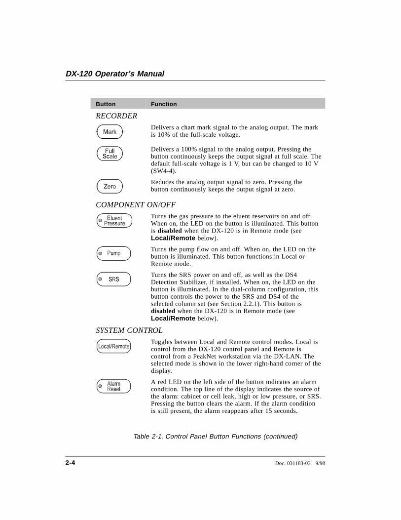
Table 2-1. Control Panel Button Functions
2 • Description
Doc. 031183-03 9/98 2-3
Button Function
RECORDER
Delivers a chart mark signal to the analog output. The markis 10% of the full-scale voltage.
Delivers a 100% signal to the analog output. Pressing thebutton continuously keeps the output signal at full scale. Thedefault full-scale voltage is 1 V, but can be changed to 10 V(SW4-4).
Reduces the analog output signal to zero. Pressing thebutton continuously keeps the output signal at zero.
COMPONENT ON/OFF
Turns the gas pressure to the eluent reservoirs on and off.When on, the LED on the button is illuminated. This buttonis disabled when the DX-120 is in Remote mode (seeLocal/Remote below).
Turns the pump flow on and off. When on, the LED on thebutton is illuminated. This button functions in Local orRemote mode.
Turns the SRS power on and off, as well as the DS4Detection Stabilizer, if installed. When on, the LED on thebutton is illuminated. In the dual-column configuration, thisbutton controls the power to the SRS and DS4 of theselected column set (see Section 2.2.1). This button isdisabled when the DX-120 is in Remote mode (seeLocal/Remote below).
SYSTEM CONTROL
Toggles between Local and Remote control modes. Local iscontrol from the DX-120 control panel and Remote iscontrol from a PeakNet workstation via the DX-LAN. Theselected mode is shown in the lower right-hand corner of thedisplay.
A red LED on the left side of the button indicates an alarmcondition. The top line of the display indicates the source ofthe alarm: cabinet or cell leak, high or low pressure, or SRS.Pressing the button clears the alarm. If the alarm conditionis still present, the alarm reappears after 15 seconds.
Table 2-1. Control Panel Button Functions (continued)
DX-120 Operator’s Manual
2-4 Doc. 031183-03 9/98
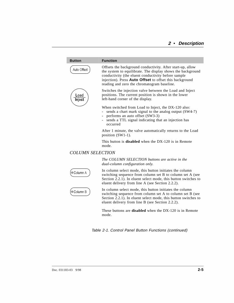
Button Function
Offsets the background conductivity. After start-up, allowthe system to equilibrate. The display shows the backgroundconductivity (the eluent conductivity before sampleinjection). Press Auto Offset to offset this backgroundreading and zero the chromatogram baseline.
Switches the injection valve between the Load and Injectpositions. The current position is shown in the lowerleft-hand corner of the display.
When switched from Load to Inject, the DX-120 also:- sends a chart mark signal to the analog output (SW4-7)- performs an auto offset (SW3-3)- sends a TTL signal indicating that an injection has occurred
After 1 minute, the valve automatically returns to the Loadposition (SW1-1).
This button is disabled when the DX-120 is in Remotemode.
COLUMN SELECTION
The COLUMN SELECTION buttons are active in thedual-column configuration only.
In column select mode, this button initiates the columnswitching sequence from column set B to column set A (seeSection 2.2.1). In eluent select mode, this button switches toeluent delivery from line A (see Section 2.2.2).
In column select mode, this button initiates the columnswitching sequence from column set A to column set B (seeSection 2.2.1). In eluent select mode, this button switches toeluent delivery from line B (see Section 2.2.2).
These buttons are disabled when the DX-120 is in Remotemode.
Table 2-1. Control Panel Button Functions (continued)
2 • Description
Doc. 031183-03 9/98 2-5
2.1.2 Pump
The pump is located on the right side of the maincompartment (see Figure 2-2). The knob on the front of thepump adjusts the flow rate from 0.5 to 4.5 mL/min.
Eluent Save Mode
If the DX-120 is idle (i.e., no control panel buttons have beenpressed and no PeakNet commands have been received) for90 minutes, the pump flow automatically decreases to 1/20thof its current flow rate and the SRS cycles on and off. Whenthis occurs, the LEDs on the Pump and SRS buttons flash.Press any button to return to the last selected flow rate.
To turn off this feature, reset the Pump Time-out DIP switch(SW1-2).
2.1.3 Configuration DIP Switches
The DIP switches on the left side of the main compartmentcontrol system parameters. The factory-set defaults can bechanged to meet specific system and application requirements(see Section B.10).
NOTEIn this manual, when a function is controlled by a DIPswitch setting, the switch and position numbers are shownin parentheses. For example: (SW1-3, 4) indicates DIPswitch 1, positions 3 and 4.
DX-120 Operator’s Manual
2-6 Doc. 031183-03 9/98
2.1.4 Eluent Reservoirs
Dionex strongly recommends degassing all eluents andstoring them in reservoirs pressurized with helium. This helpsprevent bubbles (resulting from eluent outgassing) fromforming in the pump head and the detector cell. Degassedeluents and pressurized reservoirs are especially importantwhen combining aqueous and non-aqueous components (e.g.,water and methanol). With non-aqueous components, glassreservoirs are recommended.
The single-column DX-120 includes one 2-liter plasticreservoir (P/N 044129). The dual-column DX-120 includestwo 2-liter plastic reservoirs.
The following additional reservoirs are available from Dionex:
• 1-liter plastic reservoir (P/N 044128)
• 1-liter glass reservoir with shatterproof plastic coating(P/N 044126)
• 2-liter glass reservoir with shatterproof plastic coating(P/N 044127)
The 2-liter plastic reservoir is not designed for vacuumdegassing. Do not use it for this purpose.
2 • Description
Doc. 031183-03 9/98 2-7
2.1.5 Component Panel
Chromatography components are mounted on the inside frontdoor. Figure 2-4 shows the single-column component panellayout. Figure 2-5 shows the dual-column layout.
The DX-120 is equipped with a Rheodyne injection valve(see Section 2.1.6). The following additional componentsmust be ordered separately:
• Self-Regenerating Suppressor(s) (SRS): The SRSneutralizes the eluent and enhances analyte conductivity.For a dual-column system, order two suppressors.
• Column(s): One or two analytical columns and one or twoguard columns can be installed on column clips. The clipshave larger clasps on one side for supporting 4 mmcolumns and smaller clasps on the other side for 2 mmcolumns.
• Column switching valve: The column switching valve isinstalled only in a dual-column system. The valve controlsliquid flow to the selected column (in column selectmode) or from the selected eluent (in eluent select mode).See Section 2.2 for details about dual-column systems.
• Detector cell: Only one flow-through cell is required ineither the single- or the dual-column system. Two cellmodels are available: a DX-120 standard cell (theCDM-3) and a DX-120 high-performance cell with heater(the DS4 Detection Stabilizer). The DS4 is recommendedfor applications requiring enhanced thermal stability. Seesections 2.1.7 and 2.1.8 for details about the cells and theDS4.
DX-120 Operator’s Manual
2-8 Doc. 031183-03 9/98
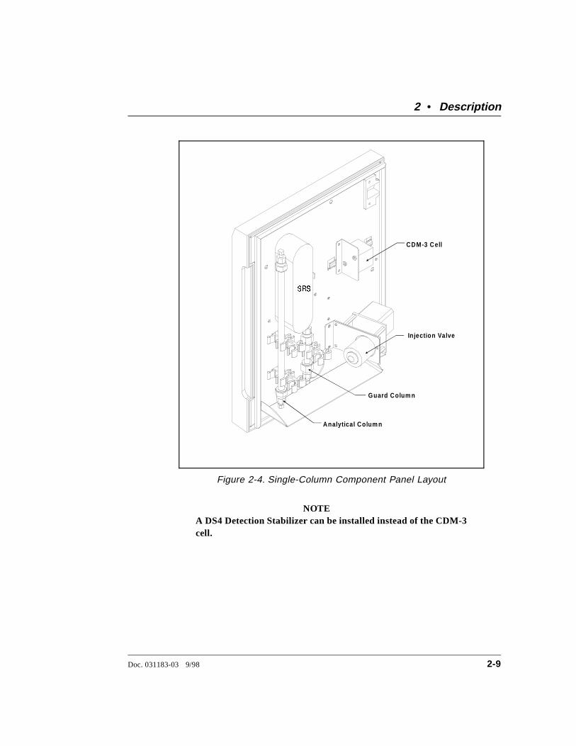
NOTEA DS4 Detection Stabilizer can be installed instead of the CDM-3cell.
CDM-3 Cell
In jection Valve
Guard Colum n
Analytical Colum n
SRS
Figure 2-4. Single-Column Component Panel Layout
2 • Description
Doc. 031183-03 9/98 2-9
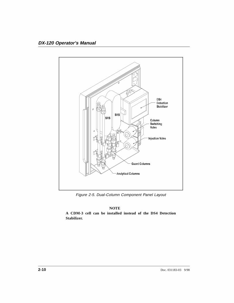
NOTEA CDM-3 cell can be installed instead of the DS4 DetectionStabilizer.
Figure 2-5. Dual-Column Component Panel Layout
DX-120 Operator’s Manual
2-10 Doc. 031183-03 9/98
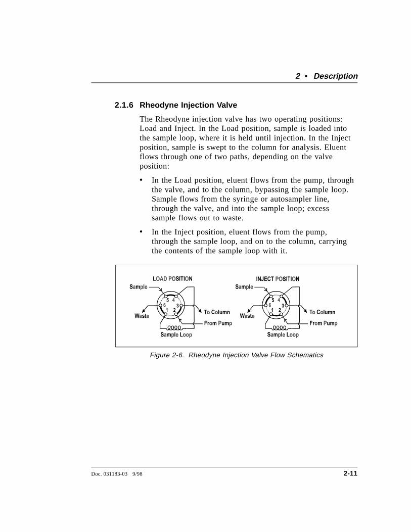
2.1.6 Rheodyne Injection Valve
The Rheodyne injection valve has two operating positions:Load and Inject. In the Load position, sample is loaded intothe sample loop, where it is held until injection. In the Injectposition, sample is swept to the column for analysis. Eluentflows through one of two paths, depending on the valveposition:
• In the Load position, eluent flows from the pump, throughthe valve, and to the column, bypassing the sample loop.Sample flows from the syringe or autosampler line,through the valve, and into the sample loop; excesssample flows out to waste.
• In the Inject position, eluent flows from the pump,through the sample loop, and on to the column, carryingthe contents of the sample loop with it.
Figure 2-6. Rheodyne Injection Valve Flow Schematics
2 • Description
Doc. 031183-03 9/98 2-11
2.1.7 Detector Cells
The DX-120 accommodates two detector cell models. TheDX-120 standard cell (CDM-3; P/N 050776) is used forapplications that do not require the enhanced baselinestability gained through thermal stabilization. For increasedthermal stabilization in high-sensitivity applications, use aDX-120 high-performance cell with heater (DS4 DetectionStabilizer; P/N 050218).
NOTEIf you change the cell model, the Cell Type DIP switches(SW4-1, 2) must be reset to select the new cell type.
Detector Cell Features
• Both cells are flow-through conductivity cells withpolymeric bodies. Two 316 stainless steel electrodes arepermanently sealed into the cell bodies.
• A sensor (thermistor) located slightly downstream fromthe electrodes senses the temperature of the liquid as itexits the cell. The measured value is used for temperaturecompensation.
• The active volume is nominally 1.25 µL for the CDM-3cell and 1.0 µL for the DX-120 high-performance cell.
• The detector cell constant for both cells has a nominalvalue of 160 cm-1.
The advanced geometry of the cells provide several benefits:
• Excellent accuracy and linearity over a broad workingrange
• Efficient sweepout and low volume for low dispersion
• Reduced sensitivity to electrode surface conditions
• Low electrode mass
• Effective temperature compensation
DX-120 Operator’s Manual
2-12 Doc. 031183-03 9/98
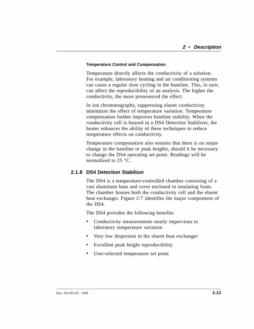
Temperature Control and Compensation
Temperature directly affects the conductivity of a solution.For example, laboratory heating and air conditioning systemscan cause a regular slow cycling in the baseline. This, in turn,can affect the reproducibility of an analysis. The higher theconductivity, the more pronounced the effect.
In ion chromatography, suppressing eluent conductivityminimizes the effect of temperature variation. Temperaturecompensation further improves baseline stability. When theconductivity cell is housed in a DS4 Detection Stabilizer, theheater enhances the ability of these techniques to reducetemperature effects on conductivity.
Temperature compensation also ensures that there is no majorchange in the baseline or peak heights, should it be necessaryto change the DS4 operating set point. Readings will benormalized to 25 °C.
2.1.8 DS4 Detection Stabilizer
The DS4 is a temperature-controlled chamber consisting of acast aluminum base and cover enclosed in insulating foam.The chamber houses both the conductivity cell and the eluentheat exchanger. Figure 2-7 identifies the major components ofthe DS4.
The DS4 provides the following benefits:
• Conductivity measurements nearly impervious tolaboratory temperature variation
• Very low dispersion in the eluent heat exchanger
• Excellent peak height reproducibility
• User-selected temperature set point
2 • Description
Doc. 031183-03 9/98 2-13
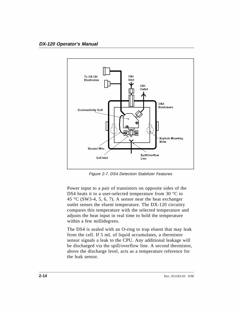
Power input to a pair of transistors on opposite sides of theDS4 heats it to a user-selected temperature from 30 °C to45 °C (SW3-4, 5, 6, 7). A sensor near the heat exchangeroutlet senses the eluent temperature. The DX-120 circuitrycompares this temperature with the selected temperature andadjusts the heat input in real time to hold the temperaturewithin a few millidegrees.
The DS4 is sealed with an O-ring to trap eluent that may leakfrom the cell. If 5 mL of liquid accumulates, a thermistorsensor signals a leak to the CPU. Any additional leakage willbe discharged via the spill/overflow line. A second thermistor,above the discharge level, acts as a temperature reference forthe leak sensor.
Figure 2-7. DS4 Detection Stabilizer Features
DX-120 Operator’s Manual
2-14 Doc. 031183-03 9/98
2.2 Dual-Column Configuration FeaturesThe dual-column configuration has two operating modes:
• Column select mode allows switching of flow from one columnset to the other.
• Eluent select mode allows switching of flow from one eluent tothe other (the column set is not switched).
The Column Select DIP switch (SW3-1) selects the mode:on=column; off=eluent.
The dual-column system option adds the following features:
• The Column A and Column B buttons on the front control panelare enabled.
• An eluent selection valve selects which eluent reservoir is used.
• A column switching valve directs flow to the selected column set(column select mode only).
2 • Description
Doc. 031183-03 9/98 2-15
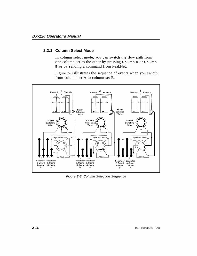
2.2.1 Column Select Mode
In column select mode, you can switch the flow path fromone column set to the other by pressing Column A or ColumnB or by sending a command from PeakNet.
Figure 2-8 illustrates the sequence of events when you switchfrom column set A to column set B.
Figure 2-8. Column Selection Sequence
DX-120 Operator’s Manual
2-16 Doc. 031183-03 9/98
1. In Step 1, eluent A is flowing to column set A.
2. In Step 2, the following occurs:
• A command is received to switch to column B.
• The eluent selection valve switches and eluent Bbegins flowing to the injection valve.
• The display flashes RINSE.
• The injection valve switches to the Inject position andthe previous eluent is cleared from the sample loop.
• A short delay occurs before the column switchingvalve switches to the new position. This allows eluentA to continue through to column set A. The duration ofthe delay depends on the current flow rate. Lower flowrates require a longer rinse time.
3. In Step 3, the following occurs:
• When eluent A has been cleared from the lines, thecolumn switching valve switches and flow proceeds tothe selected column set.
• The injection valve returns to the Load position.
• The RINSE indicator stops flashing and the displayshows the new column selection. The system is nowready for use.
NOTEThere is a small amount of eluent carryover when switchingcolumn sets. For this reason, ignore the first injection run afterswitching columns.
2 • Description
Doc. 031183-03 9/98 2-17
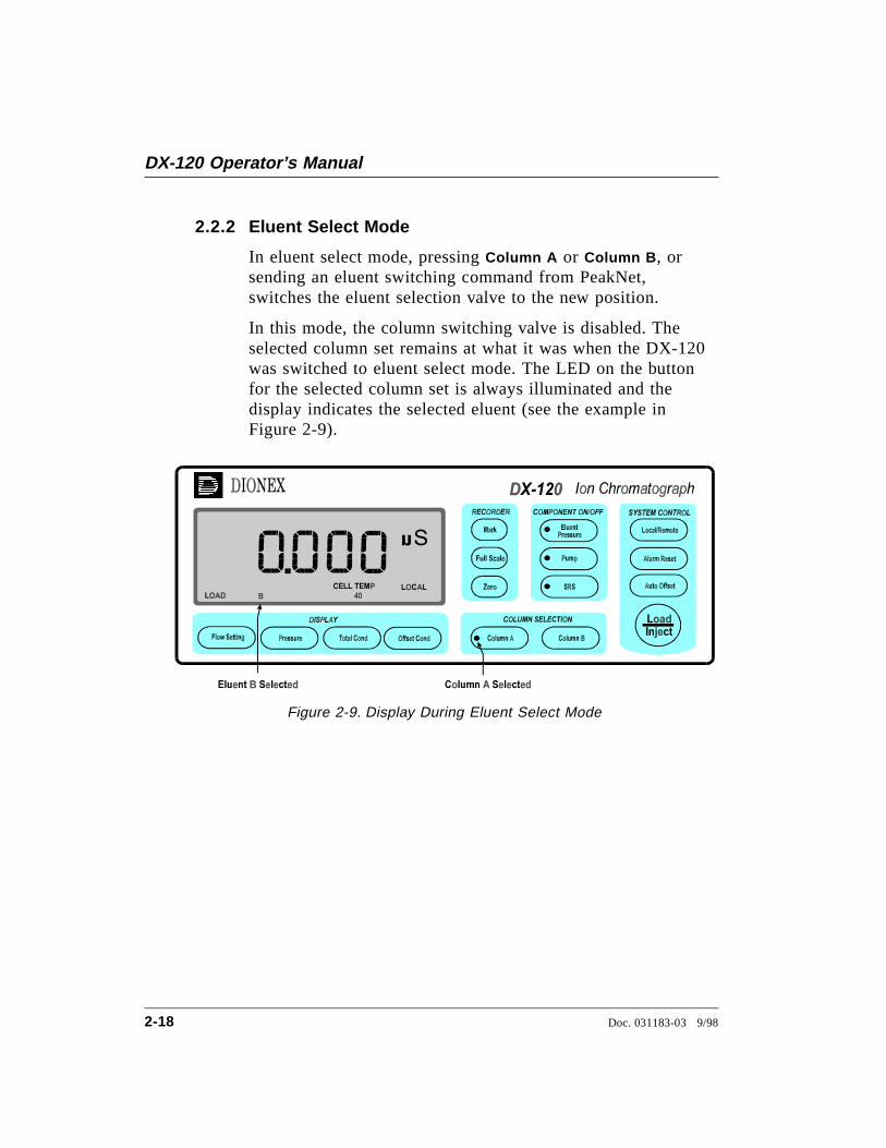
2.2.2 Eluent Select Mode
In eluent select mode, pressing Column A or Column B , orsending an eluent switching command from PeakNet,switches the eluent selection valve to the new position.
In this mode, the column switching valve is disabled. Theselected column set remains at what it was when the DX-120was switched to eluent select mode. The LED on the buttonfor the selected column set is always illuminated and thedisplay indicates the selected eluent (see the example inFigure 2-9).
Figure 2-9. Display During Eluent Select Mode
DX-120 Operator’s Manual
2-18 Doc. 031183-03 9/98

2.3 Fluid SchematicsFigure 2-10 shows the flow path through a single-column DX-120Ion Chromatograph.
0.03 - 0.07 MPa(5 - 10 psi)
Figure 2-10. DX-120 Flow Schematic: Single-Column
2 • Description
Doc. 031183-03 9/98 2-19
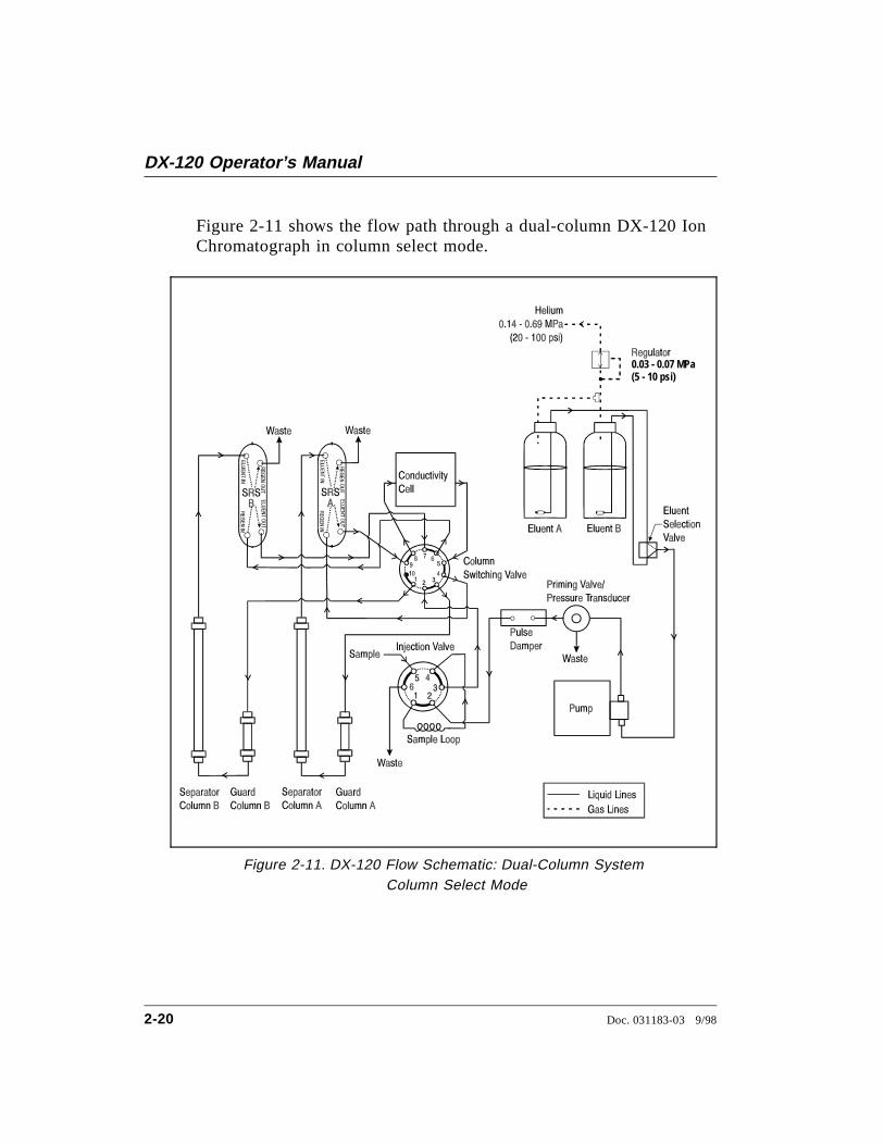
Figure 2-11 shows the flow path through a dual-column DX-120 IonChromatograph in column select mode.
0.03 - 0.07 MPa(5 - 10 psi)
Figure 2-11. DX-120 Flow Schematic: Dual-Column SystemColumn Select Mode
DX-120 Operator’s Manual
2-20 Doc. 031183-03 9/98
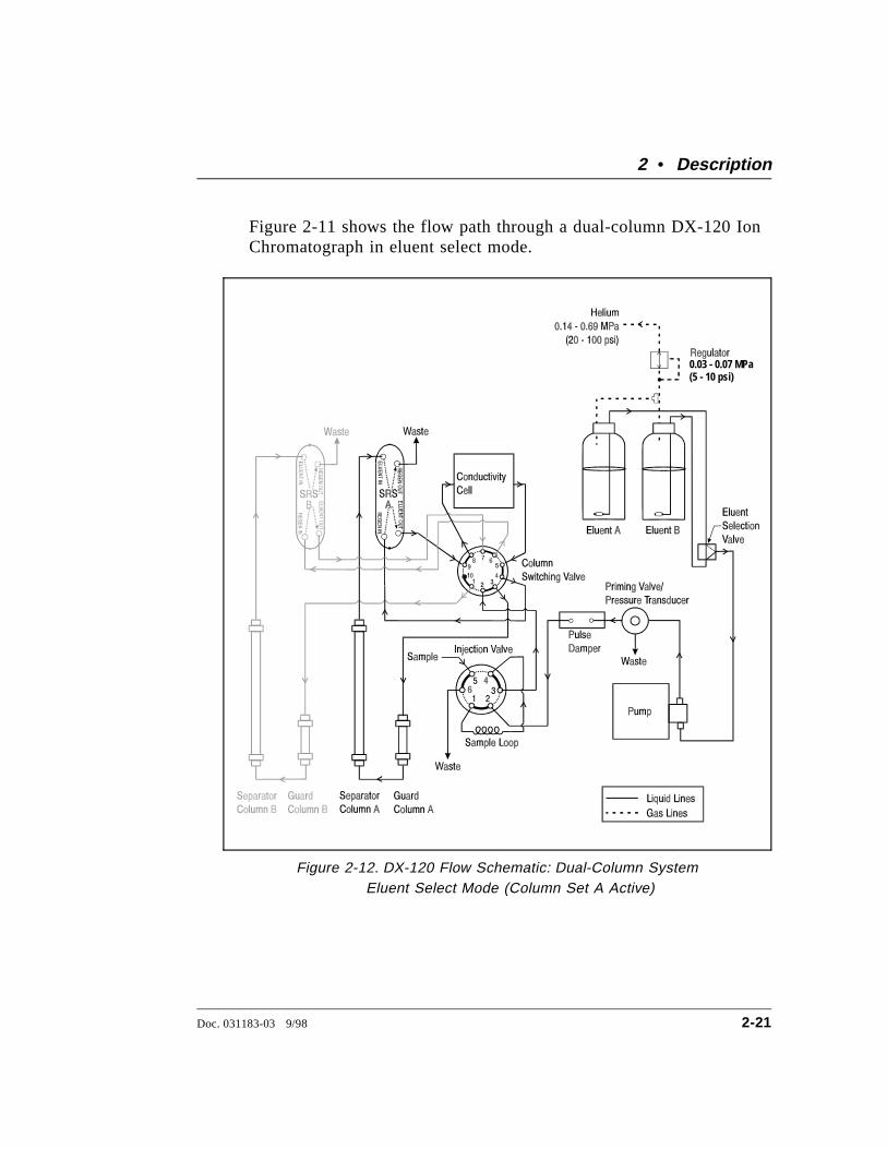
Figure 2-11 shows the flow path through a dual-column DX-120 IonChromatograph in eluent select mode.
0.03 - 0.07 MPa(5 - 10 psi)
Figure 2-12. DX-120 Flow Schematic: Dual-Column SystemEluent Select Mode (Column Set A Active)
2 • Description
Doc. 031183-03 9/98 2-21
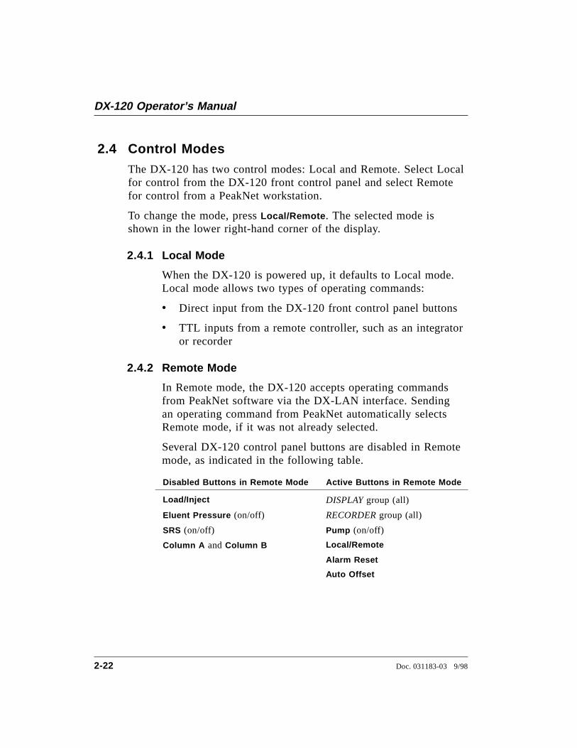
2.4 Control ModesThe DX-120 has two control modes: Local and Remote. Select Localfor control from the DX-120 front control panel and select Remotefor control from a PeakNet workstation.
To change the mode, press Local/Remote . The selected mode isshown in the lower right-hand corner of the display.
2.4.1 Local Mode
When the DX-120 is powered up, it defaults to Local mode.Local mode allows two types of operating commands:
• Direct input from the DX-120 front control panel buttons
• TTL inputs from a remote controller, such as an integratoror recorder
2.4.2 Remote Mode
In Remote mode, the DX-120 accepts operating commandsfrom PeakNet software via the DX-LAN interface. Sendingan operating command from PeakNet automatically selectsRemote mode, if it was not already selected.
Several DX-120 control panel buttons are disabled in Remotemode, as indicated in the following table.
Disabled Buttons in Remote Mode Active Buttons in Remote Mode
Load/Inject DISPLAY group (all)
Eluent Pressure (on/off) RECORDER group (all)
SRS (on/off) Pump (on/off)
Column A and Column B Local/Remote
Alarm Reset
Auto Offset
DX-120 Operator’s Manual
2-22 Doc. 031183-03 9/98
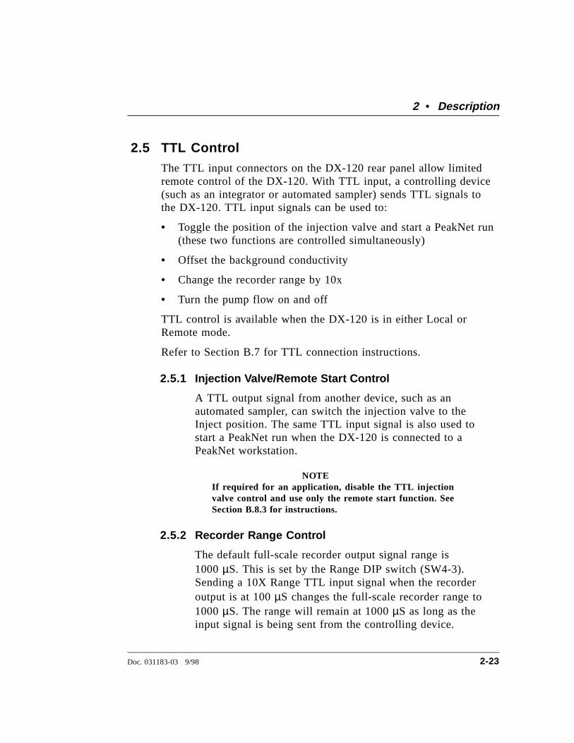
2.5 TTL ControlThe TTL input connectors on the DX-120 rear panel allow limitedremote control of the DX-120. With TTL input, a controlling device(such as an integrator or automated sampler) sends TTL signals tothe DX-120. TTL input signals can be used to:
• Toggle the position of the injection valve and start a PeakNet run(these two functions are controlled simultaneously)
• Offset the background conductivity
• Change the recorder range by 10x
• Turn the pump flow on and off
TTL control is available when the DX-120 is in either Local orRemote mode.
Refer to Section B.7 for TTL connection instructions.
2.5.1 Injection Valve/Remote Start Control
A TTL output signal from another device, such as anautomated sampler, can switch the injection valve to theInject position. The same TTL input signal is also used tostart a PeakNet run when the DX-120 is connected to aPeakNet workstation.
NOTEIf required for an application, disable the TTL injectionvalve control and use only the remote start function. SeeSection B.8.3 for instructions.
2.5.2 Recorder Range Control
The default full-scale recorder output signal range is1000 µS. This is set by the Range DIP switch (SW4-3).Sending a 10X Range TTL input signal when the recorderoutput is at 100 µS changes the full-scale recorder range to1000 µS. The range will remain at 1000 µS as long as theinput signal is being sent from the controlling device.
2 • Description
Doc. 031183-03 9/98 2-23
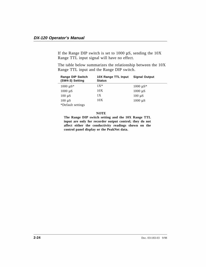
If the Range DIP switch is set to 1000 µS, sending the 10XRange TTL input signal will have no effect.
The table below summarizes the relationship between the 10XRange TTL input and the Range DIP switch.
Range DIP Switch(SW4-3) Setting
10X Range TTL InputStatus
Signal Output
1000 µS* 1X* 1000 µS*
1000 µS 10X 1000 µS
100 µS 1X 100 µS
100 µS 10X 1000 µS*Default settings
NOTEThe Range DIP switch setting and the 10X Range TTLinput are only for recorder output control; they do notaffect either the conductivity readings shown on thecontrol panel display or the PeakNet data.
DX-120 Operator’s Manual
2-24 Doc. 031183-03 9/98
3 • Operation and Maintenance
3.1 Preparing Eluents
3.1.1 Degassing Eluents
Dionex strongly recommends degassing all eluents andstoring them in reservoirs pressurized with filtered inert gas(see Section 3.1.3). This helps prevent bubbles (resultingfrom eluent outgassing) from forming in the pump and thedetector cell. Degassed eluents and pressurized reservoirs areespecially important when combining aqueous andnonaqueous components (for example, water and methanol).
Several degassing procedures can be used, including vacuumdegassing, sparging with helium, or sonication withoutvacuum. Follow the steps below for vacuum degassing:
1. Prepare the eluent required for the application. Pour itinto a clean vacuum flask and attach the flask to avacuum pump or water aspirator.
2. Vacuum degas the eluent for 5 minutes while agitating thesolution by shaking or sonication.
When using nonaqueous components, do not degas eluentsfor longer than 5 minutes; volatile compounds may be lost.
3. Remove the flask from the vacuum. Do not allow waterto flow from the aspirator back into the flask.
4. Pour the degassed eluent into a pressurizable reservoir. Becareful not to shake the eluent.
5. Install end-line filters and pressurize the reservoirs (seeSections 3.1.2 and 3.1.3).
Doc. 031183-03 9/98 3-1
3.1.2 Filtering Eluents
Always filter eluents before operation to remove smallparticulates that may contaminate the pump check valves andcause erratic flow rates or loss of prime. End-line filters(P/N 045987) are supplied in the pressurizable reservoir shipkits for this purpose.
Install an end-line filter on the end of the eluent line insidethe reservoir. To prevent air from being drawn through thelines, make sure that the end of the filter reaches the bottomof the eluent reservoir.
3.1.3 Pressurizing Eluent Reservoirs
Pressurize eluent reservoirs with filtered inert gas (preferablyhelium). Refer to the Pressurizable Reservoir InstallationInstructions for details.
1. Verify that the gas supply is connected to the HELIUMINPUT connector on the rear panel and is regulated tobetween 0.14 and 0.69 MPa (20 and 100 psi).
2. Press Eluent Pressure to turn on the gas pressure to theeluent reservoir(s). A regulator inside the DX-120regulates the pressure to between 0.03 and 0.07 MPa (5 to10 psi).
Never pressurize the reservoirs above 0.07 MPa (10 psi). Ifusing glass reservoirs, inspect them periodically forscratches or cracks.
DX-120 Operator’s Manual
3-2 Doc. 031183-03 9/98
3.2 Preparing Samples
3.2.1 Collecting and Storing
Collect samples in high density polyethylene containers thathave been thoroughly cleaned with deionized water. Do notclean containers with strong acids or detergents because theywill leave traces of ions on the container walls. These ionsmay interfere with analysis.
If samples will not be analyzed on the day they are collected,filter them through clean 0.45 µm filters immediately aftercollection; otherwise, bacteria in the samples may cause theionic concentrations to change over time. Refrigerating thesamples at 4 °C will minimize, but not eliminate, bacterialgrowth.
Analyze samples containing nitrite or sulfite as soon aspossible. Nitrite oxidizes to nitrate, and sulfite to sulfate, thusincreasing the measured concentrations of these ions in thesample. In general, samples that do not contain nitrite orsulfite can be refrigerated for at least one week with nosignificant changes in anion concentrations.
3.2.2 Pretreating
Analyze rain water, drinking water, and air particulate leachsolutions directly with no sample preparation (other thanpossibly filtering and diluting).
Filter groundwater and wastewater samples through 0.45 µmfilters before injection, unless samples were filtered aftercollection.
Before injection, pretreat samples that may contain highconcentrations of interfering substances by putting themthrough Dionex OnGuard cartridges. Refer to theInstallation and Troubleshooting Guide for OnGuardCartridges (Document No. 032943) for instructions.
3 • Operation and Maintenance
Doc. 031183-03 9/98 3-3
3.2.3 Diluting
Because the concentrations of ionic species in differentsamples can vary widely from sample to sample, no singledilution factor can be recommended for all samples of onetype. In some cases (for example, many water samples)concentrations are so low that dilution is not necessary.
Use deionized water or eluent to dilute the sample. Whenusing carbonate/bicarbonate eluents, diluting with eluentminimizes the effect of the water dip at the beginning of thechromatogram. If you dilute the sample with eluent, also useeluent to prepare the calibration blank and standards. This ismost important for fluoride and chloride, which elute near thewater dip.
To improve the accuracy of early eluting peak determinations,such as fluoride, at concentrations below 50 ppb, dilutestandards in eluent or spike the samples with concentratedeluent to minimize the water dip. For example, spike a 100mL sample with 1.0 mL of a 100 X eluent concentrate.
DX-120 Operator’s Manual
3-4 Doc. 031183-03 9/98
3.3 Operating
3.3.1 Starting Up
1. Press the power switch below the DX-120 front controlpanel (see Figure 2-2) to turn on the system power.Microprocessor code revision levels are displayed brieflyon the screen, and then the offset conductivity reading isdisplayed.
These are the conditions at power-up:
• The DX-120 is in Local mode.
• The eluent pressure, pump, and SRS are off.
• The DS4 Detection Stabilizer (if installed) is on.
• The injection and column selection valves are in theirlast selected positions.
• The offset value is reset to zero.
2. Press the power switch on the front of the pump (seeFigure 2-2) to turn on the pump power.
3. Press Eluent Pressure to pressurize the eluent reservoirs.
4. Press Pump to turn on the pump flow.
5. Press SRS to turn on the SRS power. The screen brieflydisplays the SRS current setting in mA.
6. Press Flow Rate and verify that the pump flow rate iscorrect. If necessary, pull out the knob on the front of thepump and turn it right or left to increase or decrease theflow rate. When the correct rate is displayed, push in theknob.
7. Press Offset Cond to display the offset conductivityreading.
3 • Operation and Maintenance
Doc. 031183-03 9/98 3-5
8. Allow the system to equilibrate for 15 to 20 minutes. Thescreen displays the background conductivity (theconductivity of the eluent before injecting sample). PressAuto Offset to offset the background and zero the reading.
If a DS4 is installed, system equilibration must alsoinclude the time required for the DS4 to reach operatingtemperature. The DS4 warms up at about 1 °C/minuteabove ambient. Baseline conductivity should stabilizeonce the DS4 reaches the selected temperature. The DS4temperature status appears at the bottom of the display:
• LO CELL TEMP appears and the temperature set pointflashes when the DS4 is below temperature.
• CELL TEMP appears and the set point stops flashingwhen the DS4 has reached operating temperature.
• CELL TEMP HI appears and the temperature set pointflashes when the DS4 is above operating temperature.
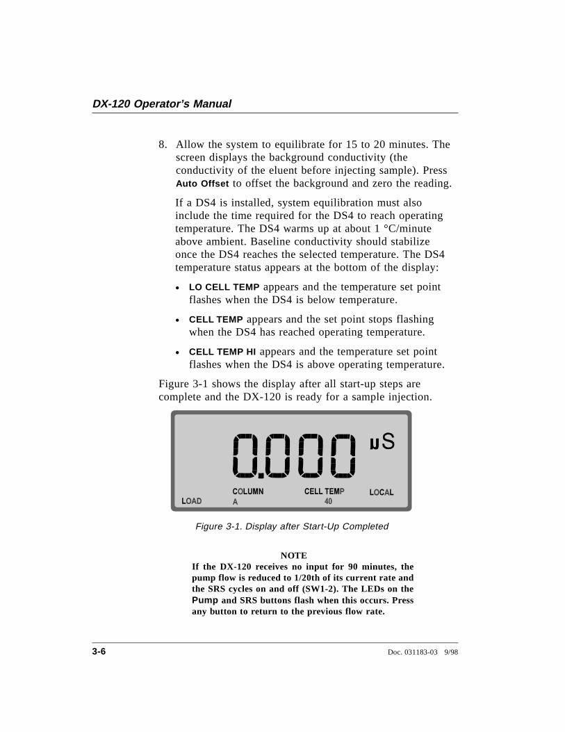
Figure 3-1 shows the display after all start-up steps arecomplete and the DX-120 is ready for a sample injection.
NOTEIf the DX-120 receives no input for 90 minutes, thepump flow is reduced to 1/20th of its current rate andthe SRS cycles on and off (SW1-2). The LEDs on thePump and SRS buttons flash when this occurs. Pressany button to return to the previous flow rate.
Figure 3-1. Display after Start-Up Completed
DX-120 Operator’s Manual
3-6 Doc. 031183-03 9/98
3.3.2 Injecting the Sample
This section describes how to inject sample when the DX-120is in Local control. PeakNet software can also be used toswitch the injection valve position.
Using a Syringe
1. Verify that LOCAL is shown at the lower-right corner ofthe display. If necessary, press Local/Remote to toggle toLocal mode.
2. Verify that LOAD is shown at the lower-left corner of thedisplay. If necessary, press Inject/Load to switch theinjection valve to the Load position.
3. Fill the syringe with a calibration standard or sample.
4. Insert the syringe into the port on the front of the DX-120(see Figure 2-2).
5. Overfill the sample loop with several sample loopvolumes. Excess sample will exit through the waste line.
6. Leave the syringe in the port.
7. Press Inject/Load to switch the injection valve to Inject.
Using an Autosampler
The autosampler output line connects to port 5 on theinjection valve. See Section B.8 for installation instructions.
1. Verify that LOCAL is shown at the lower-right corner ofthe display. If necessary, press Local/Remote to toggle toLocal mode.
2. Verify that LOAD is shown at the lower-left corner of thedisplay. If necessary, press Inject/Load to switch theinjection valve to the Load position.
3. Follow the instructions included with the autosampler toload the injection valve loop.
3 • Operation and Maintenance
Doc. 031183-03 9/98 3-7
4. Press Inject/Load to switch the injection valve to Inject.
Injection Events
By default, the following events occur after injection:
• An auto offset occurs (SW3-3), which includes two steps:
- The analog output signal is set to zero.
- The background conductivity is offset from the total,thereby zeroing the baseline conductivity value. This isthe same function as pressing Auto Offset on the frontpanel.
• An inject mark is sent out on the analog output (SW4-7).
• The Inject TTL output sends out a pulse indicating thatinjection occurred.
• After 1 minute, the injection valve returns to the Loadposition (SW1-1).
Injection Duration
To ensure complete injection of the sample, at least 10sample volumes must be pumped through the loop before thevalve is switched back to the Load position. For mostapplications, automatically returning to Load after 1 minute issufficient. Here are the maximum loop sizes for a one-minuteinjection at 1 mL/min and 2 mL/min:
• At 1 mL/min, use a loop of 100 µL or less.
(1000 µL/min)(1 sample vol/100 µL)=10 sample vol/min
• At 2 mL/min, use a loop of 200 µL or less.
(2000 µL/min)(1 sample vol/200 µL)=10 sample vol/min
If your flow rate/loop combination requires more time,disable the automatic return (SW1-1) (see Section B.10).
DX-120 Operator’s Manual
3-8 Doc. 031183-03 9/98
3.4 Using an IntegratorYou can connect an integrator, such as the Dionex 4400 or 4600Integrator, to the DX-120 and use a DIALOG or BASIC program toautomate analyses. If you also connect an autosampler, sampleloading can also be controlled. See Appendix C for integratorprogramming examples.
3.5 Running under PeakNet ControlWhen the DX-120 is connected to a PeakNet workstation via theDX-LAN interface, PeakNet software (Release 4.30 or higher) canmonitor DX-120 status and control the following functions:
• Select the position of the injection and column switching valves
• Turn the pump flow, SRS power, and eluent pressure on and off
• Perform an auto offset
• Select the pressure units displayed on the screen (MPa or psi)
• Control TTL1 and TTL2 output signals
• Control the auxiliary AC outlet (PeakNet control only)
For more information, refer to the PeakNet Software User’s Guide.
3 • Operation and Maintenance
Doc. 031183-03 9/98 3-9
3.6 Optimizing Temperature CompensationThe DX-120 built-in temperature compensation stabilizesconductivity readings by correcting for changes in ambienttemperature that occur during a run. For more information abouttemperature control and compensation, see Section 2.1.7.
3.6.1 With a DS4
Housing the cell in a DS4 Detection Stabilizer ensures thatthere is no more than a minor temperature variation in liquidreaching the cell. Thus, the temperature compensation DIPswitch setting can remain at the default of 1.7% per ºC.
Many users are able to keep their systems at a singleoperating temperature. For optimal accuracy, calibrate the cellat this temperature. If you later reset the temperature, theDX-120 temperature compensation will normalizeconductivity measurements to 25 °C (77 °F) to prevent amajor upset in system calibration. If you change the DS4 setpoint, recalibrate the cell.
If temperature-induced baseline cycling occurs, it is probablycaused by another component of the chromatography system.If the variation increases as the eluent reservoir empties,move the reservoir to a more temperature-stable environmentand/or wrap the reservoir in thermal insulation.
3.6.2 With a CDM-3 Cell
When the CDM-3 cell is installed, conductivity drifts up anddown with fluctuations in laboratory temperature. This isespecially noticeable in laboratories with very high airturnover rates or no air conditioning. Selecting the propertemperature compensation factor will minimize the effect oftemperature fluctuations.
The temperature compensation setting is selected with a DIPswitch (SW5-3, 4, 5). Three settings are available: 1.5%,1.7%, and 1.9%. Start with the default setting of 1.7%. If a
DX-120 Operator’s Manual
3-10 Doc. 031183-03 9/98
sinusoidal baseline variation of the same period as thelaboratory cooling or heating occurs, increase or decrease thetemperature compensation setting. If the baseline variationstill occurs, try the other setting.
3.7 MaintenanceThis section describes routine maintenance procedures that users canperform. All other maintenance procedures must be performed byDionex personnel.
Daily
• Check the interior of the main compartment for leaks or spills.Wipe up spills. Isolate and repair leaks (see Section 4.3). Rinseoff any dried eluent or reagent with deionized water.
• Check the waste container daily and empty when needed.
Weekly
• Once a week, check air lines for crimping or discoloration.Relocate any pinched lines. Replace damaged lines.
• Check the junction between the pump head and the metal pumpcasting for evidence of liquid leaks. Normal friction and wearmay gradually result in small liquid leaks around the piston seal.If unchecked, these leaks can gradually contaminate the pistonhousing, causing the pump to operate poorly. If leaks occur,replace the piston seals (see Section 5.9).
3 • Operation and Maintenance
Doc. 031183-03 9/98 3-11

DX-120 Operator’s Manual
3-12 Doc. 031183-03 9/98
4 • Troubleshooting
This chapter is a guide to troubleshooting problems that may occurwhile operating the DX-120. If an alarm sounds, check Section 4.1for possible causes. If an error code is displayed, check Section 4.2for possible causes. To resolve other problems, turn to the sectionthat best describes the operating problem.
If you are unable to eliminate a problem, contact Dionex for help. Inthe U.S., call Dionex Technical Support at 1-800-346-6390. Outsidethe U.S., call the nearest Dionex office.
4.1 AlarmsThree events signal an alarm condition: a tone sounds, the LED onthe Alarm Reset button blinks, and the display indicates ALARMand the alarm’s source. To clear the alarm, press Alarm Reset . If thealarm condition still exists, the alarm will reappear after 15 seconds.The alarm tone can be disabled with a DIP switch (SW3-2).
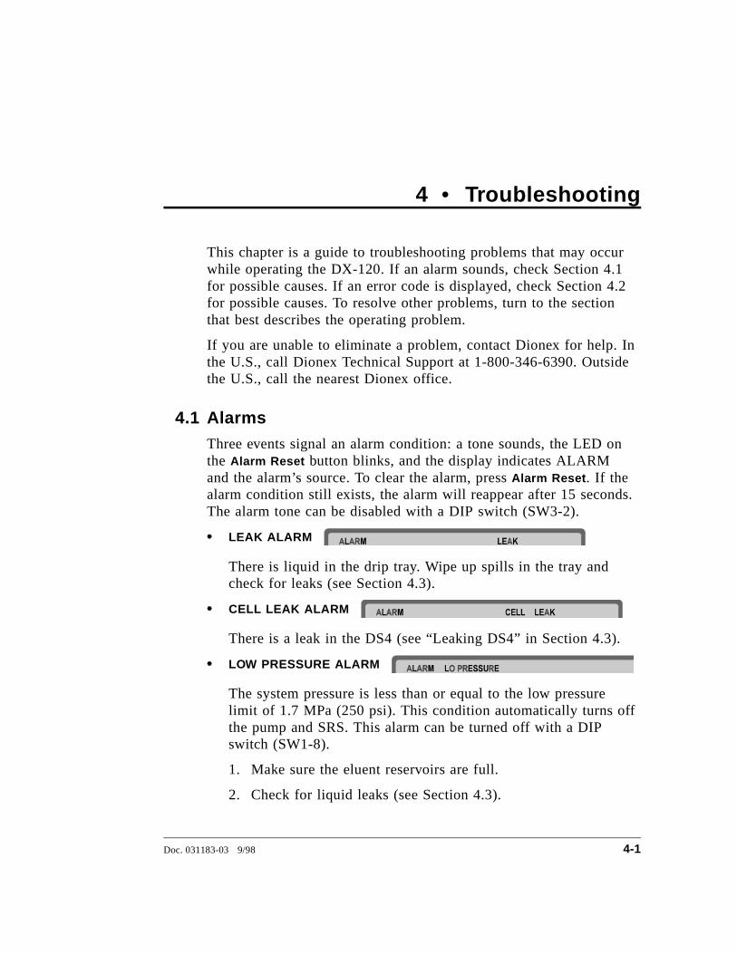
• LEAK ALARM
There is liquid in the drip tray. Wipe up spills in the tray andcheck for leaks (see Section 4.3).
• CELL LEAK ALARM
There is a leak in the DS4 (see “Leaking DS4” in Section 4.3).
• LOW PRESSURE ALARM
The system pressure is less than or equal to the low pressurelimit of 1.7 MPa (250 psi). This condition automatically turns offthe pump and SRS. This alarm can be turned off with a DIPswitch (SW1-8).
1. Make sure the eluent reservoirs are full.
2. Check for liquid leaks (see Section 4.3).
Doc. 031183-03 9/98 4-1
3. Make sure the pressure transducer waste valve is closed. Toclose the valve, turn the knob clockwise, just until tight. Donot overtighten! Overtightening may damage the valveand the pressure transducer housing.
4. Restart the pump.
5. Prime the pump (see Section B.5.1).
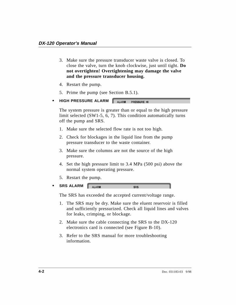
• HIGH PRESSURE ALARM
The system pressure is greater than or equal to the high pressurelimit selected (SW1-5, 6, 7). This condition automatically turnsoff the pump and SRS.
1. Make sure the selected flow rate is not too high.
2. Check for blockages in the liquid line from the pumppressure transducer to the waste container.
3. Make sure the columns are not the source of the highpressure.
4. Set the high pressure limit to 3.4 MPa (500 psi) above thenormal system operating pressure.
5. Restart the pump.
• SRS ALARM
The SRS has exceeded the accepted current/voltage range.
1. The SRS may be dry. Make sure the eluent reservoir is filledand sufficiently pressurized. Check all liquid lines and valvesfor leaks, crimping, or blockage.
2. Make sure the cable connecting the SRS to the DX-120electronics card is connected (see Figure B-10).
3. Refer to the SRS manual for more troubleshootinginformation.
DX-120 Operator’s Manual
4-2 Doc. 031183-03 9/98
4.2 Error CodesWhen an error occurs, an error code number displays in the middleof the screen. The error code remains for several seconds, and thenthe display returns to normal.
• E000
Cause: No Moduleware is installed. Moduleware is the DX-120instrument control microprocessor code.
Action: Download a new copy of the Moduleware, if the systemincludes PeakNet software, or contact Dionex for assistance.
• E001
Cause: The Column B button was pressed, although the system isconfigured for a single column.
Action: If it is a dual-column system, verify that the ColumnConfiguration DIP switch (SW1-3) is set to dual-column.
• E002
Cause: Two or more conflicting DIP switch settings.
Action: Reset the DIP switches (see Section B.10).
• E003
Cause: More than one high-pressure alarm setting is selected.The pump and SRS will turn off when this error occurs.
Action: Check the high-pressure alarm setting (SW1-5, 6, 7).One switch position must be on and the other two off.
• E004
Cause: During the rinse portion of the column switchingsequence, a command to switch columns was received from theColumn A or Column B button, or from PeakNet.
Action: The DX-120 cannot begin another column switchingsequence during the rinse cycle. Wait until the column switchingsequence is completed.
4 • Troubleshooting
Doc. 031183-03 9/98 4-3
• E005
Cause: A command to switch columns was received from eitherthe Column A or Column B button, or from PeakNet, while thepump was off or the flow rate was very low. The rinse cycle stepof the column switching sequence requires an adequate flow rateto flush the previous eluent from the system before switching.
Action: Turn on the pump or increase the flow rate.
• E006
Cause: The SRS will not turn on. Either the pump is not on orthe suppressor is disconnected.
Action: Turn on the pump. Make sure the cable connecting theSRS to the DX-120 electronics card is connected (seeFigure B-10).
4.3 Liquid Leaks• Leaking fitting
Locate the source of the leak. Tighten or, if necessary, replacethe liquid line connection (see Section 5.1). Refer to Installationof Dionex Ferrule Fittings for tightening requirements.
• Broken liquid line
Replace the line and fittings (see Section 5.1).
• Blocked or improperly installed waste line
Make sure the waste lines are not crimped or otherwise blocked.Also make sure waste lines are not elevated at any point afterthey exit the DX-120.
• Loose pump check valve housing
Make sure the check valves are firmly seated in the pump head.If they are not, tighten them carefully with an open end wrenchjust until the leak stops.
DX-120 Operator’s Manual
4-4 Doc. 031183-03 9/98
• Damaged pump piston seal
1. Replace the piston seal (see Section 5.9).
2. If the problem persists, replace the piston (see Section 5.10).
• Pump head not tight against casting
Carefully tighten the pump head mounting nuts just until the leakstops. DO NOT OVERTIGHTEN!
• Leaking pressure transducer
Make sure the liquid line connections into the transducer aretight. Refer to Installation of Dionex Ferrule Fittings fortightening requirements. Replace any damaged fittings.
Make sure the waste valve is closed. To close the valve, turn theknob clockwise, just until tight. DO NOT OVERTIGHTEN!Overtightening may damage the valve and the pressuretransducer housing.
Inspect the pressure transducer. If the waste valve is the sourceof the leak, replace the waste valve O-ring (see Section 5.11). Ifthe leak is from the rear of the transducer, contact Dionex forassistance.
• Leaking SRS
See the SRS manual for troubleshooting procedures.
• Leaking injection valve or column switching valve
Liquid leaks from behind the valve stator may indicate ascratched rotor seal. Contact Dionex for assistance.
4 • Troubleshooting
Doc. 031183-03 9/98 4-5
• Leaking DS4
Check the waste lines for blockage; trapped particles can plugthe lines and cause a restriction and/or leak. If necessary, clearthe waste lines by reversing the direction of flow.
Make sure the plumbing downstream from the DS4 is clear; ablockage may overpressurize the DS4, causing it to leak.
Make sure the downstream backpressure coils are appropriate forthe operating flow rate (see Section B.6.1).
Follow the steps below to disassemble the DS4 and inspect it forthe source of the leak.
1. Turn off the DX-120 power.
2. Disconnect the DS4 cables.
3. Disconnect the DS4 inlet and outlet lines. Do not misplacethe ferrule fittings at the end of the tubing (see Figure 4-1).
4. Remove the DS4 by lifting it upward and then pulling itaway from its mounting location. Place the DS4 on theworkbench.
5. Open both latches on the DS4 and carefully lift off the tophalf of the cover, along with its insulating foam insert,exposing an aluminum box (see Figure 4-1).
6. Remove the box from the bottom half of the cover.
7. Remove the four Phillips screws securing the top of the boxto its bottom plate. Carefully separate the two parts, exposingthe cell (see Figure 4-2). Lay the top aside, being careful notto pull or stress the group of wires that connect the two parts.
8. Check the inlet and outlet cell fittings for leaks. Tighten orreplace if necessary.
9. Dry the DS4, test for leaks, and reassemble. Make sure thefoam insert is adjusted evenly around the various DS4components, with no pinching or folding. Before latching thecover, make sure the top and bottom inserts meet on all sides.
DX-120 Operator’s Manual
4-6 Doc. 031183-03 9/98
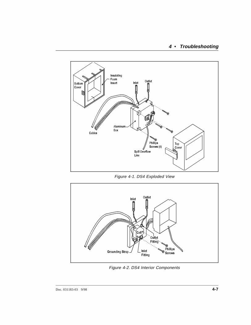
Figure 4-1. DS4 Exploded View
Figure 4-2. DS4 Interior Components
4 • Troubleshooting
Doc. 031183-03 9/98 4-7
• Liquid seeping from around cell cables
The cell has an internal leak and must be replaced. ContactDionex for assistance.
4.4 Pump Difficult to Prime• Empty reservoir and/or no eluent connected
Connect the pump inlet line to the eluent reservoir. Fill thereservoir.
• Eluent reservoir not pressurized
Connect the air line to the reservoir and press Eluent Pressure toturn on the pressure to the reservoir.
• Partially blocked end-line filter
If the end-line filter (P/N 045987) is no longer pure white,replace it.
• Liquid leaks at junction between pump head and pumpcasting
Replace the piston seal (see Section 5.9).
• Dirty or defective check valves
Clean the inlet and outlet check valves (see Section 5.8).
4.5 Pump Loses Prime• Eluent reservoir empty
Refill the reservoir.
• Liquid leaks at junction between pump heads and pumpcasting
Replace the piston seal (see Section 5.9).
• Dirty or defective check valves
Clean the inlet and outlet check valves (see Section 5.8).
DX-120 Operator’s Manual
4-8 Doc. 031183-03 9/98
4.6 Pump Does Not Start• Power switch on pump or Pump button on front panel is off
Turn on both switches.
• No power (control panel LED indicators are not lighted)
Check that the power cord is plugged in.
Check the main power fuses and replace if needed (seeSection 5.12).
4.7 No Flow• Pump not primed
Prime the pump (see Section B.5.1).
• Flow rate set to zero
Reset the flow rate.
• Broken pump piston
Replace the piston (P/N 036904) (see Section 5.10).
4.8 Excessive System Backpressure• Restriction in the hydraulic system
Check all liquid lines for crimping or blockage. Make sure theferrule fittings are not overtightened onto tubing. Refer toInstallation of Dionex Ferrule Fittings for details.
• Plugged or damaged fitting
Isolate the faulty fitting by loosening fittings one-by-one untilthe pressure returns to normal. Repair or replace the fitting (seeSection 5.1).
• Flow rate through the columns too high
1. Verify that the column flow rate matches the flow rate set forthe pump.
4 • Troubleshooting
Doc. 031183-03 9/98 4-9
2. Measure the pump flow rate, using a 10 mL graduatedcylinder and stopwatch. Calibrate the flow rate if needed (seeSection 5.7).
• Clogged column bed supports
Replace the bed supports as instructed in the column manual.
• Contaminated columns
Clean the columns as instructed in the column manual.
• Plugged Rheodyne valve passages
Contact Dionex for assistance.
4.9 Peak “Ghosting”Ghosting is the appearance of extraneous peaks in a chromatogram.These may be late-eluting peaks from a previous injection or theymay result from a contaminated, malfunctioning, or incorrectlyinstalled injection valve. These peaks may co-elute with peaks ofinterest, resulting in nonreproducible peak heights/areas.
• Insufficient time between sample injections
Wait until the previous sample has been completely eluted beforemaking another injection.
• Insufficient flush between samples
Flush the sample loop with at least 10 loop volumes of deionizedwater or sample between sample injections (see Section 3.3.2).
• Malfunctioning injection valve
Contact Dionex for assistance.
DX-120 Operator’s Manual
4-10 Doc. 031183-03 9/98

4.10 Nonreproducible Peak Height or Retention Time• Column overloading
1. Dilute the sample.
2. Change to a sample loop with a smaller volume (seeSection 5.2).
• Liquid leaks
Locate and eliminate the leaks (see Section 4.3).
• Incomplete or imprecise filling of the sample loop
1. Fill the sample loop until excess sample exits the waste line.
2. Inspect the syringe (P/N 016387, 10 cc; 016388, 1 cc) andreplace if damaged.
4.11 Abnormal Retention Time or Selectivity• System not equilibrated following an eluent change
Allow the system to equilibrate with at least 20 column volumesof eluent (for example, 30 minutes at 2.0 mL/min for 4 mmanion separator columns).
• Incorrect flow rate through system
1. Check that the correct flow rate is selected.
2. Calibrate the pump flow rate (see Section 5.7).
3. Locate and eliminate any liquid leaks (see Section 4.3).
• Contaminated or incorrect eluent
Remake the eluent using reagent grade chemicals and ASTMfiltered, Type I (18-megohm) deionized water.
• Contaminated or degraded sample
Take appropriate precautions when preparing and storing samplesto prevent contamination and degradation (see Section 3.2).
4 • Troubleshooting
Doc. 031183-03 9/98 4-11
• Contaminated column
1. Clean the column as instructed in the column manual.
2. If cleaning is unsuccessful, replace the column.
4.12 DS4 Temperature Inaccurate• CELL TEMP HI displays continuously
Verify that the set temperature is at least 5 °C above ambient(SW4-4, 5, 6, 7). Allow 30 to 60 minutes for the initial warm-upperiod. If you later select a higher set point, allow an additional3 to 7 minutes for each 5-degree increment in the set point.
The DS4 can take from 1 to 2 hours to completely cool down.
• LO CELL TEMP displays continuously
At high flow rates and temperature settings far above ambient,the DS4 requires more time to heat. In extreme cases, such as avery cold room and a high DS4 set point, the DS4 may not beable to reach the set point temperature.
• DS4 does not heat
Make sure the Cell Type DIP switches (SW4-1, 2) are set to theDS4 position (off).
Make sure that one of the DS4 temperature switch positions(SW4-4, 5, 6, 7) is on. If all switches are off, the DS4 will notheat.
Remove the cover and inspect the DS4 for broken or shortedwires or for moisture bridging the control thermistor. If a wire isbroken or shorted, replace the wire or call Dionex for assistance.If a leak has caused a short, fix the leak (see Section 4.3,“Leaking DS4”) and dry the control sensor.
DX-120 Operator’s Manual
4-12 Doc. 031183-03 9/98
4.13 No Detector Response• Cell not connected
Check the cell cable connection.
• Analog output range too high; although the display indicatesa response, no recorder response observed
Select the 100 µS range setting (SW4-3, off).
• Full-scale output too low
Select the 10.0 V full-scale setting (SW4-4, off).
• No flow from pump
Check that the LED on the Pump button is lighted. Check thepower switch on the front of the pump.
Make sure the flow rate is not set to zero.
• Detector offset out of range
Press Auto Offset on the front control panel.
• Cell electronics malfunctioning
Test the electronics as follows:
1. Disconnect the cell cable from the electronics card at the leftside of the pump compartment (see Figure B-10).
2. Set SW4-1, 2 to the off position.
3. Set SW5-8 to the on position.
4. The conductivity reading on the display should be 25.0 µS. Ifthis is not the case, there may be a problem with the cellelectronics. Contact Dionex for assistance.
4 • Troubleshooting
Doc. 031183-03 9/98 4-13
4.14 Low Detector Output• Analog output range set too high; although the display
indicates a response, no recorder response observed
Select the 100 µS range setting (SW4-3, off).
• Insufficient sample injected
Increase the injection size or concentration. See Section 5.2 forinformation on changing the sample loop size.
• Cell out of calibration
Recalibrate the cell (see Section 5.6).
4.15 High Detector Output• Auto offset not activated recently
Press Auto Offset on the front panel before making an injection.
• Background not suppressed by SRS
Check that the SRS is on (the LED on the SRS button should beilluminated).
Check the SRS regenerant out line for bubbles; if there are nobubbles, the suppressor may be contaminated. Refer to the SRSmanual for troubleshooting guidance.
• Sample concentration too high
Dilute the sample or install a smaller sample loop (seeSection 5.2).
• Wrong eluent
Make sure you are using the correct eluent.
• Cell out of calibration
Recalibrate the cell (see Section 5.6).
DX-120 Operator’s Manual
4-14 Doc. 031183-03 9/98
4.16 Noisy or Drifting Baseline• Flow system leak ahead of cell; erratic baseline
Check all fittings and liquid lines for leaks. Tighten or, ifnecessary, replace all liquid line connections. Refer toInstallation of Dionex Ferrule Fittings for tighteningrequirements.
• Pump not properly primed
Prime the pump (see Section B.5.1).
• Rapid changes in ambient temperature
Redirect heating and air conditioning vents away from theDX-120.
Replace the CDM-3 cell with a DS4 Detection Stabilizer(P/N 050218).
• Insufficient system equilibration following changes tooperating parameters; especially apparent when operating athigh sensitivities
Allow longer system equilibration time before starting operation.
• Air trapped in cell; excessive regular pulses in baseline
Check that the correct backpressure coils are installed after thecell and before the SRS (see Section B.6.1).
• Incorrect SRS operating conditions
Refer to the SRS manual for troubleshooting information.
• Temperature compensation setting not optimized
Optimize the setting (see Section 3.6).
• DS4 above or below set point
Wait for the DS4 to reach the selected temperature beforebeginning operation. The display will indicate CELL TEMP andthe selected temperature. If the temperature is above or below theset point, CELL TEMP HI or LO CELL TEMP is displayed.
4 • Troubleshooting
Doc. 031183-03 9/98 4-15

DX-120 Operator’s Manual
4-16 Doc. 031183-03 9/98
5 • Service
This chapter describes routine service procedures that users mayperform. Other service procedures must be performed by Dionexpersonnel.
NOTESElectronics components are not customer-serviceable. Anyrepairs involving the DX-120 electronics must be performed byDionex personnel.
The CPU card contains a lithium battery. If it is necessary toreplace the CPU card, dispose of the used battery according tothe manufacturer’s instructions.
Before replacing any part, refer to the troubleshooting information inChapter 4 to isolate the cause of the problem. When orderingreplacement parts, please include the DX-120 model number andserial number. To contact Dionex in the U.S., call 1-800-346-6390.Outside the U.S., call the nearest Dionex office.
Substituting non-Dionex parts may impair DX-120 performance,thereby voiding the product warranty. Refer to the warrantystatement in the Dionex Terms and Conditions for more information.
Doc. 031183-03 9/98 5-1
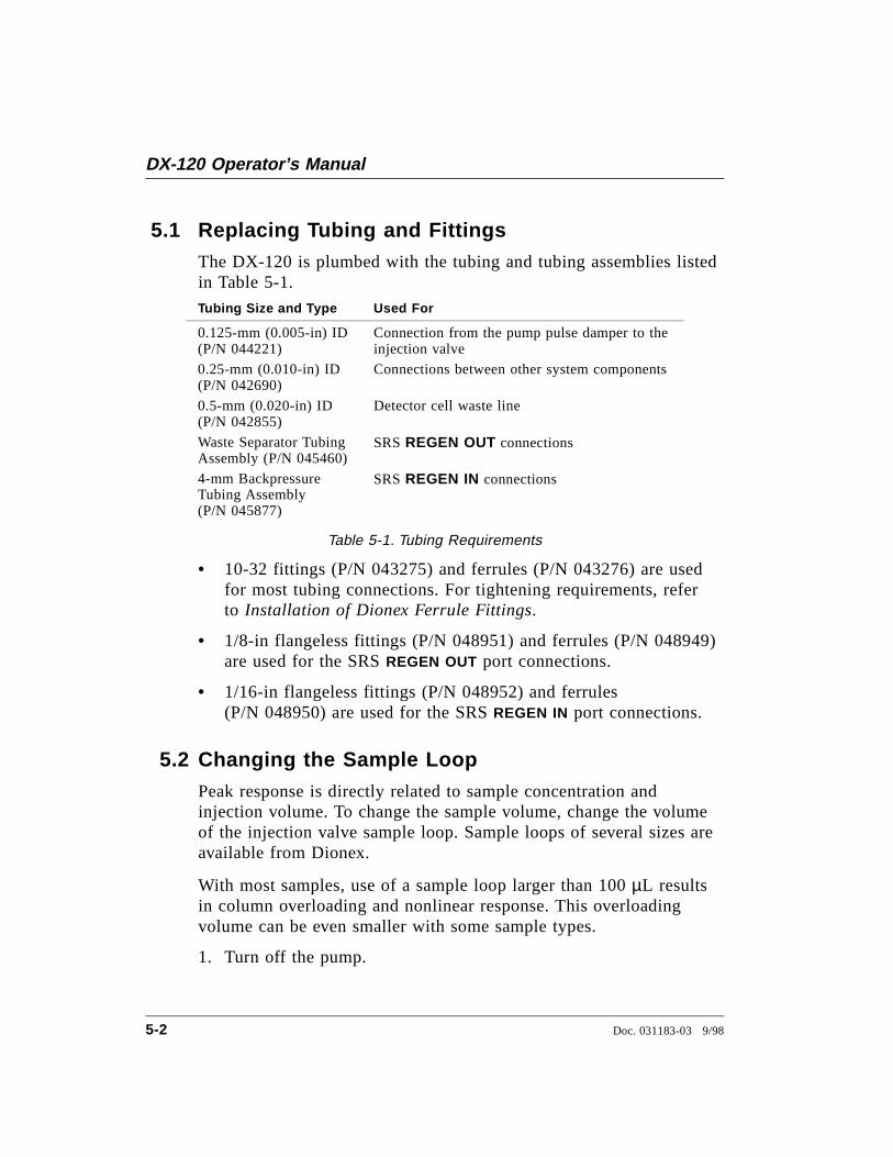
5.1 Replacing Tubing and FittingsThe DX-120 is plumbed with the tubing and tubing assemblies listedin Table 5-1.
Tubing Size and Type Used For
0.125-mm (0.005-in) ID(P/N 044221)
Connection from the pump pulse damper to theinjection valve
0.25-mm (0.010-in) ID (P/N 042690)
Connections between other system components
0.5-mm (0.020-in) ID (P/N 042855)
Detector cell waste line
Waste Separator TubingAssembly (P/N 045460)
SRS REGEN OUT connections
4-mm BackpressureTubing Assembly (P/N 045877)
SRS REGEN IN connections
Table 5-1. Tubing Requirements
• 10-32 fittings (P/N 043275) and ferrules (P/N 043276) are usedfor most tubing connections. For tightening requirements, referto Installation of Dionex Ferrule Fittings.
• 1/8-in flangeless fittings (P/N 048951) and ferrules (P/N 048949)are used for the SRS REGEN OUT port connections.
• 1/16-in flangeless fittings (P/N 048952) and ferrules(P/N 048950) are used for the SRS REGEN IN port connections.
5.2 Changing the Sample LoopPeak response is directly related to sample concentration andinjection volume. To change the sample volume, change the volumeof the injection valve sample loop. Sample loops of several sizes areavailable from Dionex.
With most samples, use of a sample loop larger than 100 µL resultsin column overloading and nonlinear response. This overloadingvolume can be even smaller with some sample types.
1. Turn off the pump.
DX-120 Operator’s Manual
5-2 Doc. 031183-03 9/98
2. Open the DX-120 door.
3. Disconnect the sample loop from ports 1 and 4 on the injectionvalve (see Figure B-20).
4. Install the new sample loop between ports 1 and 4 on theinjection valve.
5.3 Isolating a Restriction in the Liquid PlumbingA restriction in the liquid plumbing will cause excessive systembackpressure.
1. Begin pumping eluent through the system (including thecolumns) at the flow rate normally used.
2. Follow the appropriate hydraulic schematic (see Figure 2-10 or2-11) and work backward through the system, beginning at thecell exit. One at a time, loosen each fitting and observe thepressure. The connection at which the pressure drops abnormallyindicates the point of restriction.
If the restriction has caused such high pressure that the systemcannot be operated, you must work forward through the flowschematic, adding parts one at a time until an abnormal pressureincrease (and hence, the restriction) is found.
3. If the restriction is in the tubing or fitting, remove the restrictioneither by back flushing or by replacing the tubing or fitting.
5.4 Replacing the DS4 CellFollow the steps below to disassemble the DS4 and replace the cell.After replacing the cell, recalibrate it (see Section 5.6).
1. Turn off the DX-120 power.
2. Disconnect the DS4 cables.
3. Disconnect the DS4 inlet and outlet lines. Do not misplace theferrule fittings at the end of the tubing (see Figure 5-1).
5 • Service
Doc. 031183-03 9/98 5-3
4. Remove the DS4 by lifting it upward and then pulling it awayfrom its mounting location. Place the DS4 on the workbench.
5. Open both latches on the DS4 and carefully lift off the top halfof the cover, along with its insulating foam insert, exposing analuminum box (see Figure 4-1).
6. Remove the box from the bottom half of the cover.
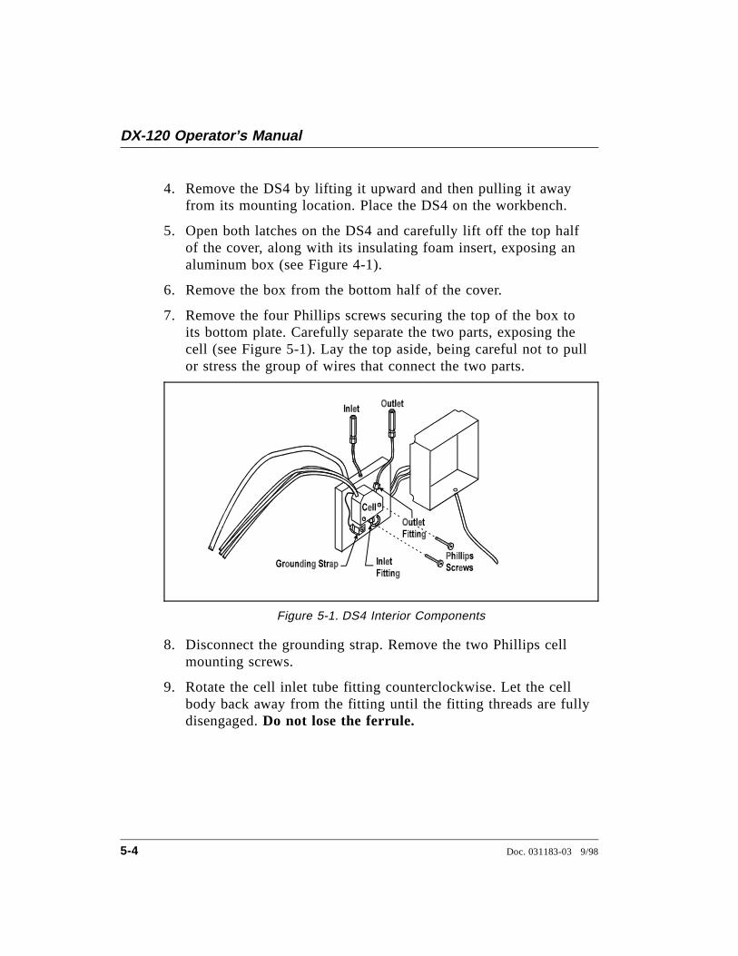
7. Remove the four Phillips screws securing the top of the box toits bottom plate. Carefully separate the two parts, exposing thecell (see Figure 5-1). Lay the top aside, being careful not to pullor stress the group of wires that connect the two parts.
8. Disconnect the grounding strap. Remove the two Phillips cellmounting screws.
9. Rotate the cell inlet tube fitting counterclockwise. Let the cellbody back away from the fitting until the fitting threads are fullydisengaged. Do not lose the ferrule.
Figure 5-1. DS4 Interior Components
DX-120 Operator’s Manual
5-4 Doc. 031183-03 9/98
10. Check that the end of the inner Tefzel tubing is flush with theend of the plastic sleeve. If necessary, trim the sleeve slightly toprevent dispersion. Push the tubing into the new cell until itbottoms out in the hole; then, hold the tubing in place whiletightening the nut.
11. After testing for liquid leaks, dry the DS4 and reassemble. Makesure the foam insert is adjusted evenly around the variouscomponents, with no pinching or folding. Before latching thecover, make sure the top and bottom inserts meet on all sides.
12. Reconnect the DS4 cables and turn on the DX-120 power. Now,calibrate the cell constant (see Section 5.6).
5.5 Cleaning Cell ElectrodesIf you suspect fouling, clean and recalibrate the cell (seeSection 5.6).
1. Prepare the solutions listed below, using filtered ASTM Type I(or better) deionized water. Pour the prepared solutions intolabeled containers.
HNO3 is corrosive and a strong irritant. Avoid breathingthe vapors. Always prepare the cleaning solution in a fumehood. Wear gloves and goggles.
a. 3 M HNO3 cleaning solution: Dilute 200 mL concentratedHNO3 (s.g. 1.42) to one liter with deionized water.
b. 0.01 M KCl stock solution: Dissolve 0.7456 g ofreagent-grade KCl in one liter of deionized water.
c. 0.001 M KCl calibration solution: Dilute 100 mL of stocksolution to 1 liter with deionized water.
2. Connect the container of 0.001 M KCl to the pump.
3. Disconnect the line between the suppressor outlet and the cell (orDS4 inlet) at the suppressor. In a dual-column system, disconnectthe cell inlet line from port 8 on the column switching valve.
5 • Service
Doc. 031183-03 9/98 5-5
4. Connect a female luer adapter (P/N 024305) to the tubing, usinga union (P/N 042806).
5. Fill a 10 mL syringe (P/N 016387) with 3 M HNO3 solution.Screw the syringe into the luer adapter.
6. Turn off the DX-120 main power switch.
7. Inject 5 mL of HNO3 through the cell.
8. After two minutes, push the remaining 5 mL of solution throughthe cell. Wait 2 minutes.
9. Fill the syringe with 10 mL of deionized water. Inject the waterthrough the cell.
10. Turn on the DX-120 main power switch. Continue to Step 3 ofSection 5.6 to calibrate the cell constant.
5.6 Calibrating the Cell ConstantCalibrate the cell after installing a new cell or after cleaning the cellelectrodes. The cell does not require routine calibration.
1. Disconnect the pump eluent line from port 2 on the injectionvalve.
2. Disconnect the line between the suppressor outlet and the cell orDS4 inlet at the suppressor. In a dual-column system, disconnectthe cell inlet line from port 8 on the column switching valve.
3. Connect the eluent line from the pump directly to the inlet of thecell or DS4, using a union (P/N 042806).
4. Pump 0.001 M KCl calibration solution through the cell at2.0 mL/min. After 5 minutes, reduce the flow rate to the valuetypically used during analysis and pump for an additionalminute. Conductivity is slightly flow-rate sensitive, so select theflow rate used in the majority of your applications.
DX-120 Operator’s Manual
5-6 Doc. 031183-03 9/98
5. Set the temperature compensation to 1.7% (SW5-5, on; SW5-4and 6, off). This temperature compensation value can be used formost applications. When measuring absolute conductivity,determine the optimal value for each batch of calibration solution(see Section 3.6).
6. Disconnect the cell cable from the cell connector on the edge ofthe electronics card (see Figure B-10).
7. Press the Auto Offset button. With the cell disconnected, this isthe zero conductivity point. Press Offset Cond to display theoffset conductivity.
8. Reconnect the cell cable.
9. Locate the Cell Calibration potentiometer on the electronics card(see Figure B-10). Continue pumping calibration solutionthrough the cell. Use the tuning screwdriver (P/N 035617) fromthe Ship Kit to adjust the potentiometer until the display valueequals 147 ± 2 µS.
10. Replace the container of 0.001 M KCl calibration solution with acontainer of deionized water. Pump deionized water through theliquid lines at 2.0 mL/min for at least 5 minutes to flush thecalibration solution from the system.
11. Reconnect the pump to the injection valve.
12. In a single-column system, reconnect the liquid line from the cellor DS4 inlet to the suppressor outlet. In a dual-column system,reconnect the line from the cell inlet to the column switchingvalve.
13. Reset the temperature compensation to the optimal value for theeluent in use (SW5-4, 5, 6). The cell is now calibrated and readyfor operation.
5 • Service
Doc. 031183-03 9/98 5-7
5.7 Calibrating the Pump Flow Rate1. Disconnect the line from port 3 on the injection valve (see
Figure B-20).
2. Connect an 11 MPa (1600 psi) backpressure device, or a piece ofnarrow-bore PEEK tubing that will provide 11 MPa (1600 psi) ofbackpressure, to port 3 on the injection valve. Route the otherend of the backpressure tubing to waste.
3. Fill the eluent reservoir with deionized water.
4. Turn on the pump and set the flow rate to 1.2 mL/min.
5. Pump deionized water through the system for at least 15minutes to allow the system to equilibrate.
6. Collect the water into a tared beaker for 5 minutes. Weigh thecollected water. It should be 6.00 ± 0.05 g.
7. If the collected water is not within the above range, locate thePump Flow Setting Adjust potentiometer on the electronics card(see Figure B-10). Continue pumping deionized water throughthe cell. Use the tuning screwdriver (P/N 035617) from the ShipKit to adjust the potentiometer until the flow rate displaycorresponds to the weight of the collected water. For example, ifyou collected 5.5 g, adjust the flow rate to 1.1 mL/min.
5.8 Cleaning and Replacing Pump Check ValvesA dirty check valve causes an erratic flow rate. It may also cause thepump to lose prime and/or be difficult to reprime.
1. Prime the pump (see Section B.5.1). If the pump does not stayprimed, proceed to the next step.
2. Turn off the main power switch on the DX-120 and disconnectthe main power cord.
3. Disconnect the tube fittings from both the inlet and outlet checkvalve housings (see Figure 2-2).
DX-120 Operator’s Manual
5-8 Doc. 031183-03 9/98
4. Using a 1/2-in box wrench or an adjustable wrench, carefullyremove both check valve housings from the pump head.
5. Place the check valves in a beaker of methanol and sonicate oragitate for several minutes.
6. Rinse each check valve thoroughly with filtered, deionized water.
7. Reinstall the check valves in the pump head. Be sure to installthe inlet check valve on the bottom of the head and the outletcheck valve on the top. Tighten only enough to seat.
Overtightening may damage the pump head or the checkvalve housing and crush the check valve seats.
8. Reconnect the liquid lines. Turn on the power switch on theDX-120 front panel.
9. Prime the pump (see Section B.5.1). If the pump will not prime,and you have eliminated all other possible causes of the problem,replace both check valves (inlet check valve, P/N 038273; outletcheck valve, P/N 042761).
5.9 Replacing a Pump Piston SealA damaged piston seal allows leakage around the piston at the headmounting plate or around the base of the pump head. Flow rates willbe unstable and there may be baseline noise.
1. Turn off the main power switch on the DX-120 and disconnectthe main power cord.
2. Disconnect the tube fittings from the inlet and outlet checkvalves.
5 • Service
Doc. 031183-03 9/98 5-9
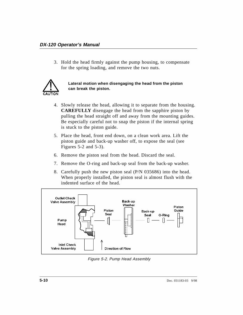
3. Hold the head firmly against the pump housing, to compensatefor the spring loading, and remove the two nuts.
Lateral motion when disengaging the head from the pistoncan break the piston.
4. Slowly release the head, allowing it to separate from the housing.CAREFULLY disengage the head from the sapphire piston bypulling the head straight off and away from the mounting guides.Be especially careful not to snap the piston if the internal springis stuck to the piston guide.
5. Place the head, front end down, on a clean work area. Lift thepiston guide and back-up washer off, to expose the seal (seeFigures 5-2 and 5-3).
6. Remove the piston seal from the head. Discard the seal.
7. Remove the O-ring and back-up seal from the back-up washer.
8. Carefully push the new piston seal (P/N 035686) into the head.When properly installed, the piston seal is almost flush with theindented surface of the head.
Figure 5-2. Pump Head Assembly
DX-120 Operator’s Manual
5-10 Doc. 031183-03 9/98

9. Press a new back-up seal (P/N 036901) into the O-ring (P/N035776). If necessary, also replace the O-ring. Then press theO-ring and back-up seal into the back-up washer.
10. Press the back-up washer into the head, followed by the pistonguide.
11. Remove the spring, spring guide, spring retainer, and piston fromthe pump housing (see Figure 5-3). Inspect the interior of thehousing for liquid and corrosion. Clean up any spills andcarefully clean any signs of corrosion from the interior of thehousing.
12. Clean and inspect the piston. If it is scored or scratched, replaceit (see Section 5.10).
13. Reinstall the piston, spring retainer, spring guide, and spring inthe pump housing.
14. Carefully slide the pump head straight onto the mounting guides.Guide the spring onto the piston guide. Apply gentle pressure topush the piston through the seal.
Avoid all lateral motion when sliding the head onto thepiston. Failure to slide the head straight on will break thepiston, as well as damage the piston seal and back-up seal.
15. Hold the head firmly against the pump housing and replace thetwo nuts. Use a wrench to tighten them evenly.
16. Reconnect the liquid lines to the inlet and outlet check valves.
17. Reconnect the main power cord and turn on the main powerswitch.
18. Prime the pump (see Section B.5.1).
5 • Service
Doc. 031183-03 9/98 5-11
5.10 Replacing a Pump PistonContinued leaking from around the pump head after replacing thepiston seal indicates a scratched or broken piston.
1. Turn off the main power switch on the DX-120 and disconnectthe main power cord.
2. Disconnect the tube fittings from the inlet and outlet checkvalves.
3. While holding the head firmly against the pump housing, tocompensate for the spring loading, remove the two nuts.
Lateral motion when disengaging the head from the pistonwill break the piston.
4. Slowly release the head and allow it to separate from thehousing. CAREFULLY disengage the head from the sapphirepiston by pulling the head straight off and away from themounting guides. Be especially careful not to snap the piston ifthe spring is stuck to the piston guide.
5. Remove the piston guide, spring, spring guide, spring retainer,and piston by pulling them straight out, away from the pumphousing (see Figure 5-3).
6. If the piston is broken, replace the piston seal and the back-up seal(see Section 5.9). This will prevent pieces of broken piston fromscratching the new piston assembly.
7. Remove the retainer ring (P/N 035010) from the old pistonassembly and install it on the new piston assembly (P/N 036904).
8. Carefully slide the spring retainer onto the piston assembly.
9. Slide the assembled piston back into the piston housing.
DX-120 Operator’s Manual
5-12 Doc. 031183-03 9/98

10. Slide the spring over the piston, positioning it flush against thespring retainer.
11. Carefully slide the pump head straight onto the alignmentrods. Guide the spring over the piston guide. Gently push thepiston through the seal.
Avoid all lateral motion when sliding the head onto thepiston. Failure to slide the head straight over the pistonwill break the piston, as well as damage the piston sealand back-up seal.
12. Hold the head firmly against the pump housing and replace thetwo nuts. Use a wrench to tighten them evenly.
13. Reconnect the liquid lines to the check valve housings.
14. Reconnect the main power cord and turn on the main powerswitch.
15. Prime the pump (see Section B.5.1).
Figure 5-3. Piston Pump Assembly
5 • Service
Doc. 031183-03 9/98 5-13
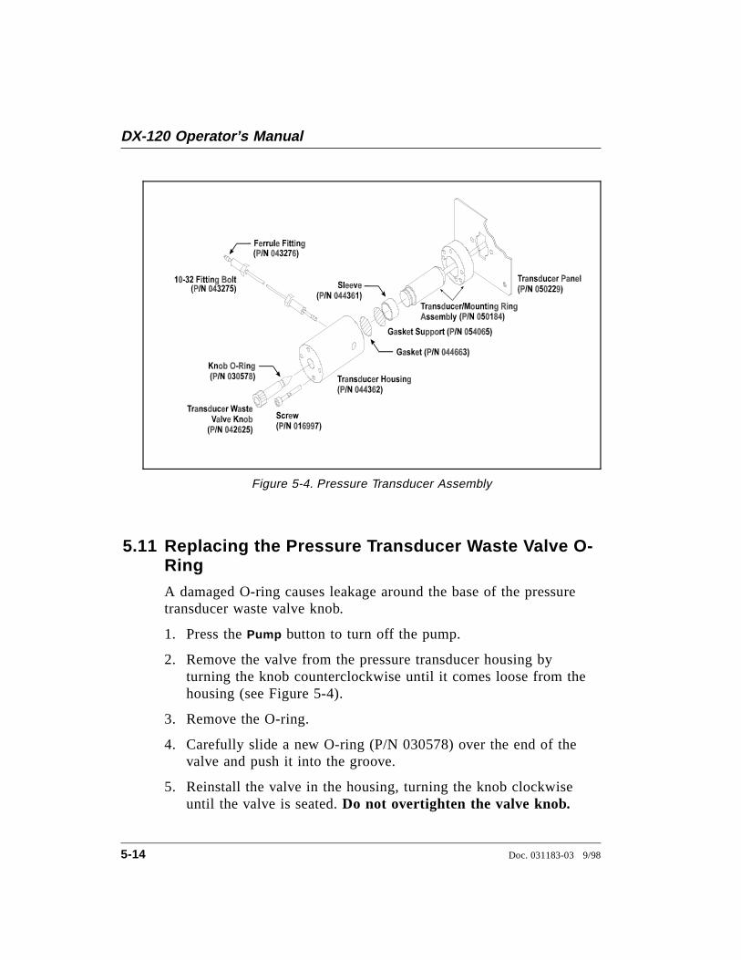
5.11 Replacing the Pressure Transducer Waste Valve O-RingA damaged O-ring causes leakage around the base of the pressuretransducer waste valve knob.
1. Press the Pump button to turn off the pump.
2. Remove the valve from the pressure transducer housing byturning the knob counterclockwise until it comes loose from thehousing (see Figure 5-4).
3. Remove the O-ring.
4. Carefully slide a new O-ring (P/N 030578) over the end of thevalve and push it into the groove.
5. Reinstall the valve in the housing, turning the knob clockwiseuntil the valve is seated. Do not overtighten the valve knob.
Figure 5-4. Pressure Transducer Assembly
DX-120 Operator’s Manual
5-14 Doc. 031183-03 9/98
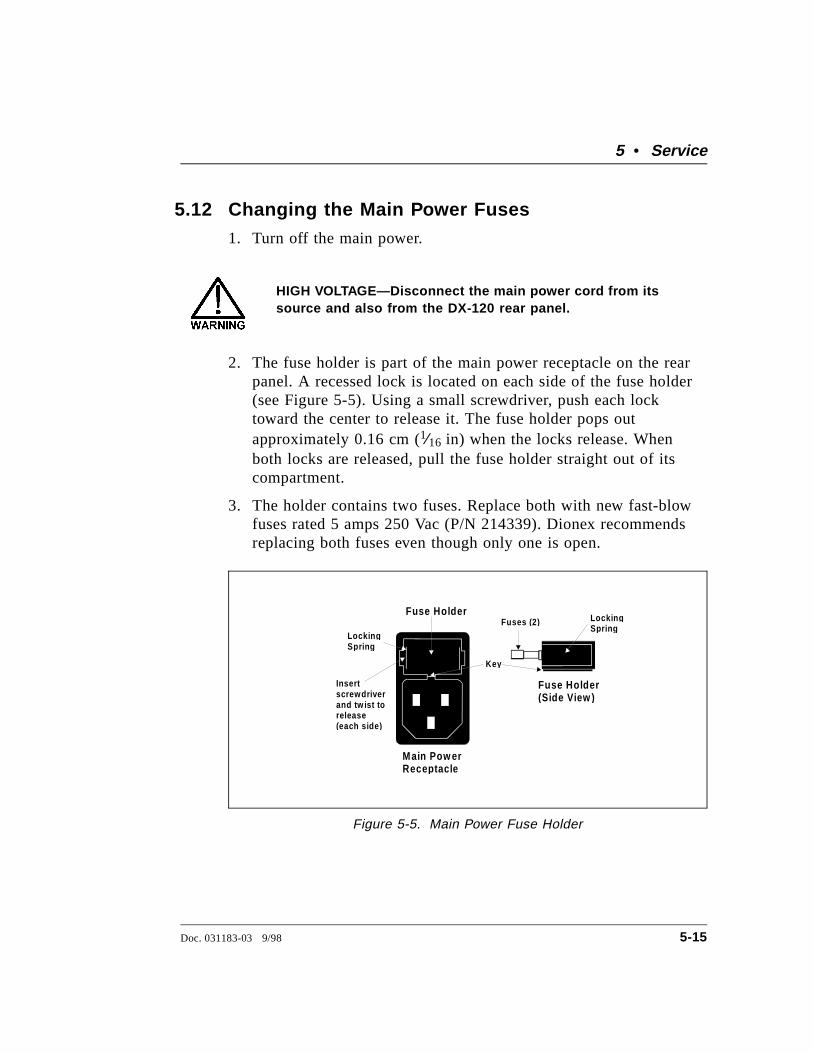
5.12 Changing the Main Power Fuses1. Turn off the main power.
HIGH VOLTAGE—Disconnect the main power cord from itssource and also from the DX-120 rear panel.
2. The fuse holder is part of the main power receptacle on the rearpanel. A recessed lock is located on each side of the fuse holder(see Figure 5-5). Using a small screwdriver, push each locktoward the center to release it. The fuse holder pops outapproximately 0.16 cm (1⁄16 in) when the locks release. Whenboth locks are released, pull the fuse holder straight out of itscompartment.
3. The holder contains two fuses. Replace both with new fast-blowfuses rated 5 amps 250 Vac (P/N 214339). Dionex recommendsreplacing both fuses even though only one is open.
Fuse Holder
Fuse Holder(Side View )
Fuses (2)
Insertscrewdriverand tw ist torelease(each side )
Lockin gSp rin g
Lockin gSprin g
Main Pow erRecep tacle
Key
Figure 5-5. Main Power Fuse Holder
5 • Service
Doc. 031183-03 9/98 5-15
4. Reinsert the fuse holder into its compartment. The fuse holder iskeyed to fit only in its proper orientation. Apply sufficientpressure evenly against the holder to engage the two locks. Theholder is flush against the panel when both locks are engaged.
5. Reconnect the main power cord and turn on the power.
DX-120 Operator’s Manual
5-16 Doc. 031183-03 9/98
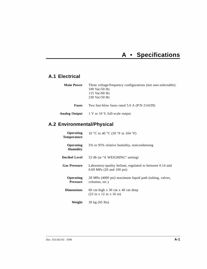
A • Specifications
A.1 Electrical
Main Power Three voltage/frequency configurations (not user-selectable):100 Vac/50 Hz115 Vac/60 Hz 230 Vac/50 Hz
Fuses Two fast-blow fuses rated 5.0 A (P/N 214339)
Analog Output 1 V or 10 V, full-scale output
A.2 Environmental/Physical
OperatingTemperature
10 °C to 40 °C (50 °F to 104 °F)
OperatingHumidity
5% to 95% relative humidity, noncondensing
Decibel Level 53 db (at “A WEIGHING” setting)
Gas Pressure Laboratory-quality helium, regulated to between 0.14 and0.69 MPa (20 and 100 psi)
OperatingPressure
28 MPa (4000 psi) maximum liquid path (tubing, valves,columns, etc.)
Dimensions 60 cm high x 30 cm x 40 cm deep(23 in x 12 in x 16 in)
Weight 30 kg (65 lbs)
Doc. 031183-03 9/98 A-1
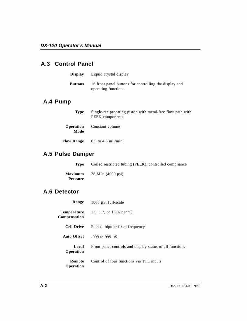
A.3 Control Panel
Display Liquid crystal display
Buttons 16 front panel buttons for controlling the display andoperating functions
A.4 Pump
Type Single-reciprocating piston with metal-free flow path withPEEK components
OperationMode
Constant volume
Flow Range 0.5 to 4.5 mL/min
A.5 Pulse Damper
Type Coiled restricted tubing (PEEK), controlled compliance
MaximumPressure
28 MPa (4000 psi)
A.6 Detector
Range 1000 µS, full-scale
TemperatureCompensation
1.5, 1.7, or 1.9% per ºC
Cell Drive Pulsed, bipolar fixed frequency
Auto Offset -999 to 999 µS
LocalOperation
Front panel controls and display status of all functions
RemoteOperation
Control of four functions via TTL inputs
DX-120 Operator’s Manual
A-2 Doc. 031183-03 9/98
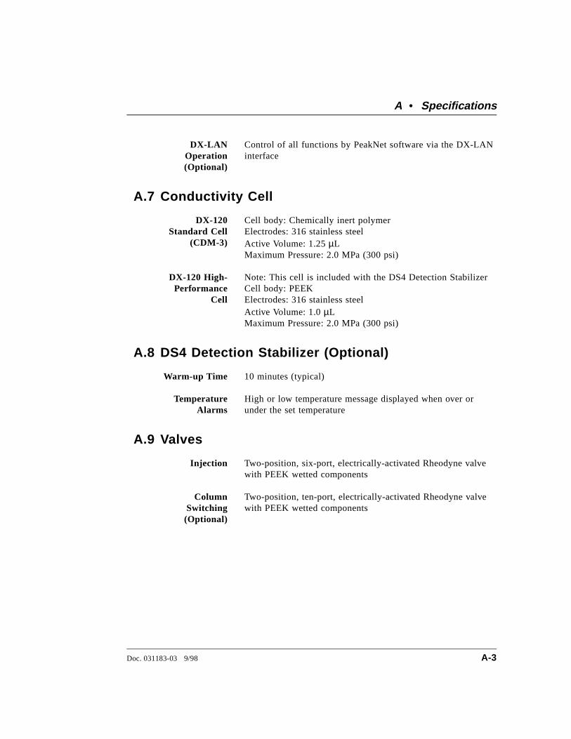
DX-LANOperation(Optional)
Control of all functions by PeakNet software via the DX-LANinterface
A.7 Conductivity Cell
DX-120Standard Cell
(CDM-3)
Cell body: Chemically inert polymerElectrodes: 316 stainless steelActive Volume: 1.25 µLMaximum Pressure: 2.0 MPa (300 psi)
DX-120 High-Performance
Cell
Note: This cell is included with the DS4 Detection StabilizerCell body: PEEKElectrodes: 316 stainless steelActive Volume: 1.0 µLMaximum Pressure: 2.0 MPa (300 psi)
A.8 DS4 Detection Stabilizer (Optional)
Warm-up Time 10 minutes (typical)
TemperatureAlarms
High or low temperature message displayed when over orunder the set temperature
A.9 Valves
Injection Two-position, six-port, electrically-activated Rheodyne valvewith PEEK wetted components
ColumnSwitching(Optional)
Two-position, ten-port, electrically-activated Rheodyne valvewith PEEK wetted components
A • Specifications
Doc. 031183-03 9/98 A-3
A.10 Delay Volume
System Total <5 mL
DX-120 Operator’s Manual
A-4 Doc. 031183-03 9/98
B • Installation
This chapter provides instructions for the initial installation of theDX-120. Instructions for installing optional features, such as theDS4 Detection Stabilizer and the DX-LAN, are also provided.
B.1 Facility Requirements• Make sure the DX-120 installation site meets the power and
environmental specifications listed in Appendix A.
• Install the DX-120 on a sturdy workbench at a height thatensures convenient viewing of the front panel display and accessto the interior.
Use caution when lifting the DX-120, which weighs 30 kg(65 lbs). Lift the DX-120 only from the non-slip pads oneach side of the cabinet bottom (see Figure 2-1). Liftingfrom the front panel door will damage the door hinges.
B.2 Installation Overview• Connect the power cord
• Place the waste lines in a waste container
• Connect the gas supply line
• (Optional) Connect the DX-LAN network cable
• Connect the eluent reservoir(s)
• Set up the pump
• Install the chromatography components (SRS and columns)
• (Optional) Connect an autosampler
• (Optional) Connect a chart recorder or integrator
Doc. 031183-03 9/98 B-1
• Set the configuration DIP switches
The DX-120 Ship Kit (P/N 050130) contains all items necessary forcompleting the installation.
B.3 Rear Panel Connections
B.3.1 Power Connection
1. A label on the DX-120 rear panel indicates the linefrequency (50 or 60 Hz) and voltage (100, 115, 230 VAC)for which the system is designed (see Figure B-1). Makesure the frequency and voltage are appropriate for yourlocation. If you are unsure, consult an electrician.
2. Connect the power cord (IEC 320 C13) from the mainpower receptacle on the rear panel (see Figure B-1) to agrounded power source.
SHOCK HAZARD—To avoid electrical shock, a groundedreceptacle must be used. Do not operate or connect to ACpower mains without an earthed ground connection.
The power supply cord is used as the main disconnectdevice. Make sure the outlet is located near the DX-120 andis easily accessible.
DX-120 Operator’s Manual
B-2 Doc. 031183-03 9/98
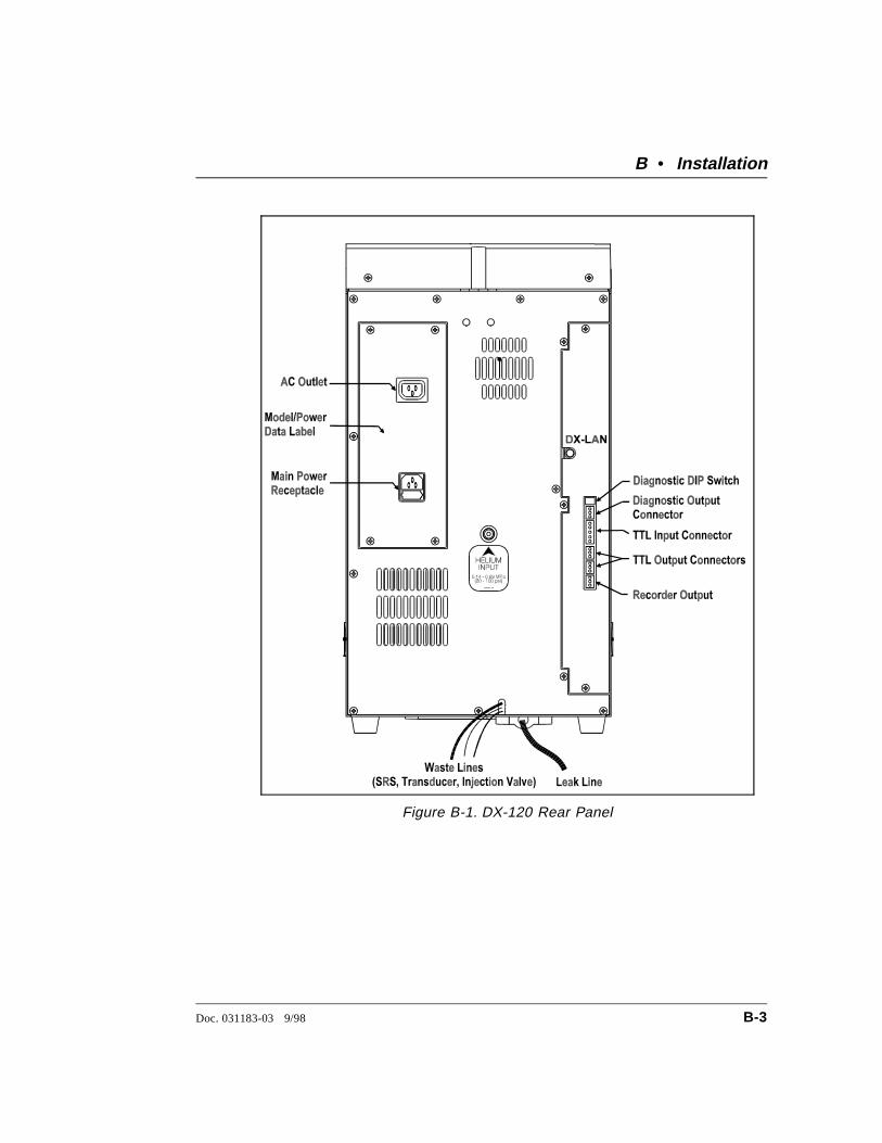
Figure B-1. DX-120 Rear Panel
B • Installation
Doc. 031183-03 9/98 B-3
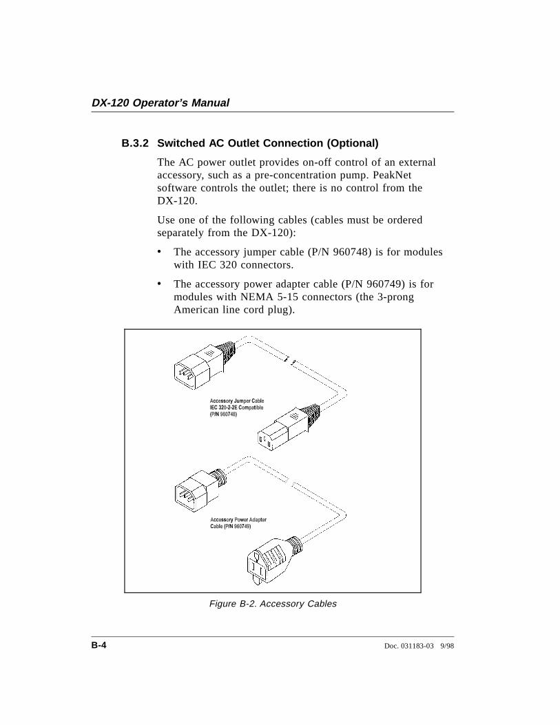
B.3.2 Switched AC Outlet Connection (Optional)
The AC power outlet provides on-off control of an externalaccessory, such as a pre-concentration pump. PeakNetsoftware controls the outlet; there is no control from theDX-120.
Use one of the following cables (cables must be orderedseparately from the DX-120):
• The accessory jumper cable (P/N 960748) is for moduleswith IEC 320 connectors.
• The accessory power adapter cable (P/N 960749) is formodules with NEMA 5-15 connectors (the 3-prongAmerican line cord plug).
Figure B-2. Accessory Cables
DX-120 Operator’s Manual
B-4 Doc. 031183-03 9/98
B.3.3 Waste Lines
Untape the coiled waste lines from the rear panel and placethe ends into a waste container. To prevent waste siphoningback into the system, make sure the tubing is not bent,pinched, or elevated at any point.
B.3.4 Gas Connection
Locate the 3-mm (0.062-in) ID tubing (P/N 030089) providedin the DX-120 Ship Kit. Push one end into the gas connectoron the rear panel (see Figure B-1). Connect the other end to asource of laboratory-quality helium regulated to between 0.14and 0.69 MPa (20 and 100 psi).
B • Installation
Doc. 031183-03 9/98 B-5
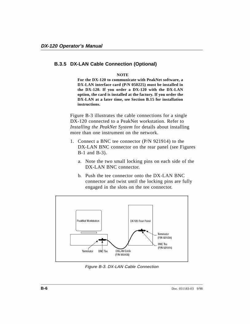
B.3.5 DX-LAN Cable Connection (Optional)
NOTEFor the DX-120 to communicate with PeakNet software, aDX-LAN interface card (P/N 050225) must be installed inthe DX-120. If you order a DX-120 with the DX-LANoption, the card is installed at the factory. If you order theDX-LAN at a later time, see Section B.15 for installationinstructions.
Figure B-3 illustrates the cable connections for a singleDX-120 connected to a PeakNet workstation. Refer toInstalling the PeakNet System for details about installingmore than one instrument on the network.
1. Connect a BNC tee connector (P/N 921914) to theDX-LAN BNC connector on the rear panel (see FiguresB-1 and B-3).
a. Note the two small locking pins on each side of theDX-LAN BNC connector.
b. Push the tee connector onto the DX-LAN BNCconnector and twist until the locking pins are fullyengaged in the slots on the tee connector.
Figure B-3. DX-LAN Cable Connection
DX-120 Operator’s Manual
B-6 Doc. 031183-03 9/98
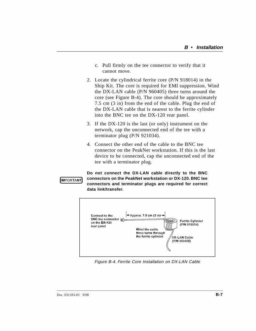
c. Pull firmly on the tee connector to verify that itcannot move.
2. Locate the cylindrical ferrite core (P/N 918014) in theShip Kit. The core is required for EMI suppression. Windthe DX-LAN cable (P/N 960405) three turns around thecore (see Figure B-4). The core should be approximately7.5 cm (3 in) from the end of the cable. Plug the end ofthe DX-LAN cable that is nearest to the ferrite cylinderinto the BNC tee on the DX-120 rear panel.
3. If the DX-120 is the last (or only) instrument on thenetwork, cap the unconnected end of the tee with aterminator plug (P/N 921034).
4. Connect the other end of the cable to the BNC teeconnector on the PeakNet workstation. If this is the lastdevice to be connected, cap the unconnected end of thetee with a terminator plug.
Do not connect the DX-LAN cable directly to the BNCconnectors on the PeakNet workstation or DX-120. BNC teeconnectors and terminator plugs are required for correctdata link/transfer.
Figure B-4. Ferrite Core Installation on DX-LAN Cable
B • Installation
Doc. 031183-03 9/98 B-7
B.4 Eluent Reservoir Connections1. Untape the coil of red air tubing from the reservoir tray on the
top of the DX-120. Push the end of the tube firmly onto thebarbed connector on the eluent reservoir cap assembly.
2. Untape the coil of white eluent tubing from the reservoir trayand screw the tube end-fitting securely into the eluent fitting onthe reservoir cap.
B.5 Pump Setup
NOTEAlways filter eluents through a 0.45 µm filter to remove smallparticulates that may contaminate the pump. Install an end-linefilter (P/N 045987) on the end of each eluent reservoir line. Filtersare supplied in the pressurizable reservoir ship kits. See thePressurizable Reservoir Installation Instructions for details.
B.5.1 Priming the Pump
1. Fill the eluent reservoir with the eluent required for theapplication or, if you will be calibrating the pump flowrate, with deionized water.
2. Lower the outlet line of the reservoir cap assembly intothe reservoir. Handtighten the cap.
3. Press Eluent Pressure on the front control panel topressurize the reservoir.
4. Open the pressure transducer waste valve (see Figure 2-2)by turning the knob counterclockwise two turns. Whenthe valve is open, eluent flows directly from the pump towaste.
5. Press Pump on the front control panel to turn on thepump. Press Flow Setting to display the pump flow rate.
6. Pull out the pump flow adjustment knob and adjust theflow rate to 2.0 mL/min. Push the knob back in.
DX-120 Operator’s Manual
B-8 Doc. 031183-03 9/98
7. After about 10 seconds, adjust the flow rate to the settingrequired for the application.
8. Close the pressure transducer waste valve and let thesystem flush and equilibrate for 10 minutes.
B.5.2 Checking the Pump Flow Rate Calibration
Check the pump flow rate calibration at installation andwhenever you change applications.
1. Disconnect the line from port 3 on the injection valve if itis currently connected to either the guard column or thecolumn switching valve (see Figure B-20).
2. Connect one of the following to port 3 on the injectionvalve: either an 11 MPa (1600 psi) backpressure device ora piece of narrow-bore PEEK tubing that will provide 11MPa (1600 psi) of backpressure. Route the other end ofthe backpressure tubing to waste.
3. Fill the eluent reservoir with deionized water.
4. Turn on the pump and set the flow rate to 1.2 mL/min.
5. Pump deionized water through the system for at least15 minutes to allow the system to equilibrate.
6. Collect the water into a tared beaker for 5 minutes.
7. Weigh the collected water. If it is not 6.00 ± 0.05 g, seeSection 5.7 for flow rate calibration instructions.
B • Installation
Doc. 031183-03 9/98 B-9
B.6 Connections to Chromatography ComponentsThe DX-120 injection valve, column switching valve (if installed),pump, and cell or DS4 connections are plumbed before shipping.The DX-120 Ship Kit contains tubing assemblies for completing theSRS and column connections.
NOTEFor shipping purposes, unions are installed between unconnectedlines from the cell and valves. Remove these unions beforebeginning the SRS and column installation procedure.
The DX-120 can be plumbed for three operating modes:
• AutoSuppression Recycle mode (SRS required), shown inFigure B-5.
• Nonsuppressed mode, shown in Figure B-6. Conductivitymeasurements made when no suppressor is in-line may shownoticeable baseline drift.
• AutoSuppression with External Regenerant mode. This mode isrequired if the eluent contains organic solvents.
This section contains installation instructions for theAutoSuppression and Nonsuppressed modes. Refer to the SRSmanual for information about using the AutoSuppression withExternal Regenerant mode.
DX-120 Operator’s Manual
B-10 Doc. 031183-03 9/98
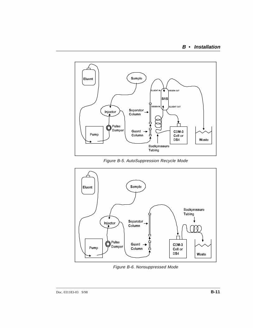
Figure B-5. AutoSuppression Recycle Mode
Figure B-6. Nonsuppressed Mode
B • Installation
Doc. 031183-03 9/98 B-11
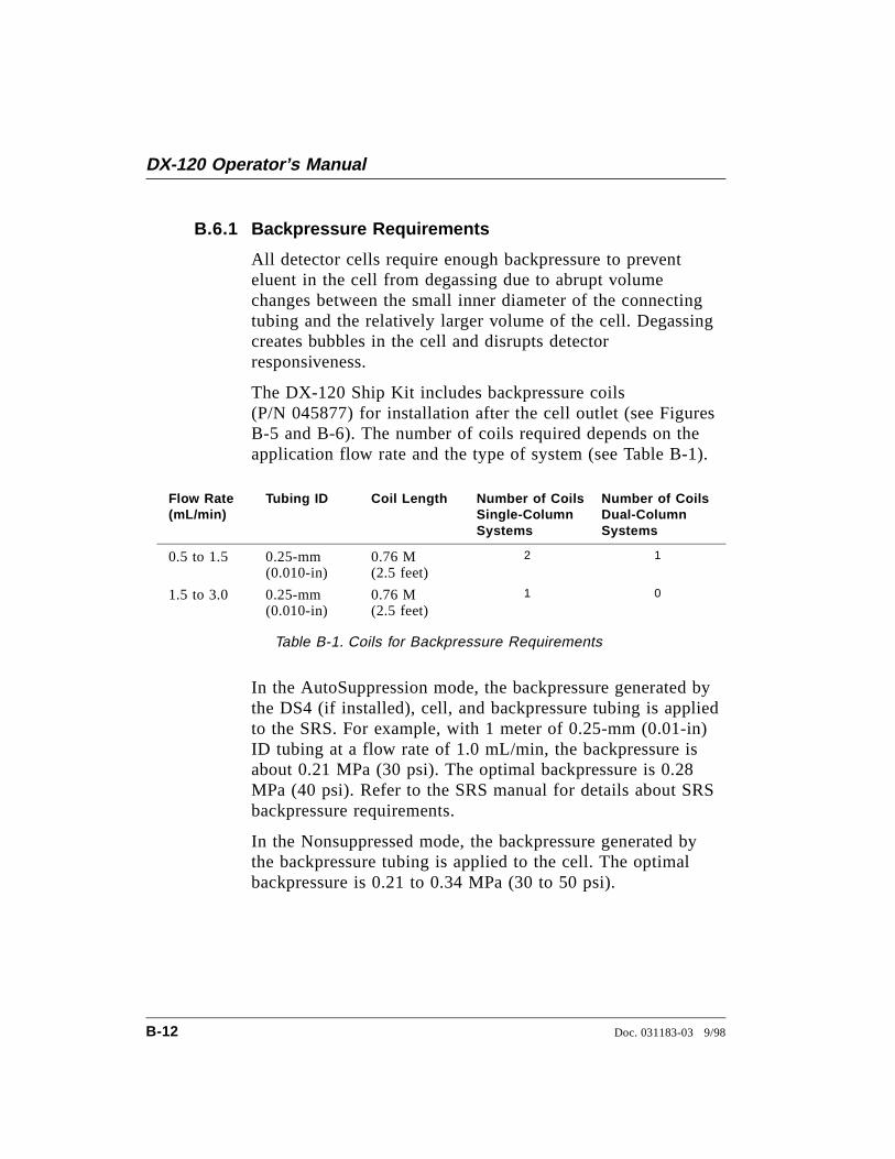
B.6.1 Backpressure Requirements
All detector cells require enough backpressure to preventeluent in the cell from degassing due to abrupt volumechanges between the small inner diameter of the connectingtubing and the relatively larger volume of the cell. Degassingcreates bubbles in the cell and disrupts detectorresponsiveness.
The DX-120 Ship Kit includes backpressure coils(P/N 045877) for installation after the cell outlet (see FiguresB-5 and B-6). The number of coils required depends on theapplication flow rate and the type of system (see Table B-1).
Flow Rate(mL/min)
Tubing ID Coil Length Number of CoilsSingle-ColumnSystems
Number of CoilsDual-ColumnSystems
0.5 to 1.5 0.25-mm(0.010-in)
0.76 M (2.5 feet)
2 1
1.5 to 3.0 0.25-mm(0.010-in)
0.76 M (2.5 feet)
1 0
Table B-1. Coils for Backpressure Requirements
In the AutoSuppression mode, the backpressure generated bythe DS4 (if installed), cell, and backpressure tubing is appliedto the SRS. For example, with 1 meter of 0.25-mm (0.01-in)ID tubing at a flow rate of 1.0 mL/min, the backpressure isabout 0.21 MPa (30 psi). The optimal backpressure is 0.28MPa (40 psi). Refer to the SRS manual for details about SRSbackpressure requirements.
In the Nonsuppressed mode, the backpressure generated bythe backpressure tubing is applied to the cell. The optimalbackpressure is 0.21 to 0.34 MPa (30 to 50 psi).
DX-120 Operator’s Manual
B-12 Doc. 031183-03 9/98
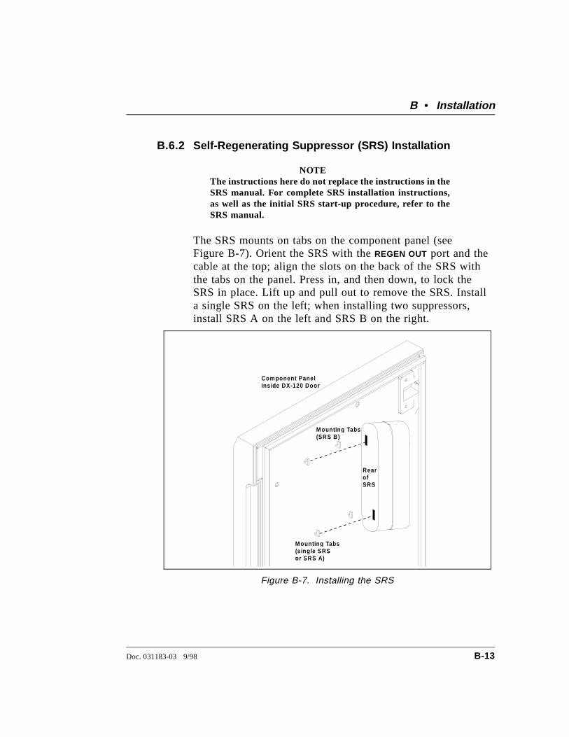
B.6.2 Self-Regenerating Suppressor (SRS) Installation
NOTEThe instructions here do not replace the instructions in theSRS manual. For complete SRS installation instructions,as well as the initial SRS start-up procedure, refer to theSRS manual.
The SRS mounts on tabs on the component panel (seeFigure B-7). Orient the SRS with the REGEN OUT port and thecable at the top; align the slots on the back of the SRS withthe tabs on the panel. Press in, and then down, to lock theSRS in place. Lift up and pull out to remove the SRS. Installa single SRS on the left; when installing two suppressors,install SRS A on the left and SRS B on the right.
RearofSRS
M ountin g Tabs(sin g le SRSor SRS A)
Com ponent Panelinside DX-120 Door
M ountin g Tabs(SRS B)
Figure B-7. Installing the SRS
B • Installation
Doc. 031183-03 9/98 B-13
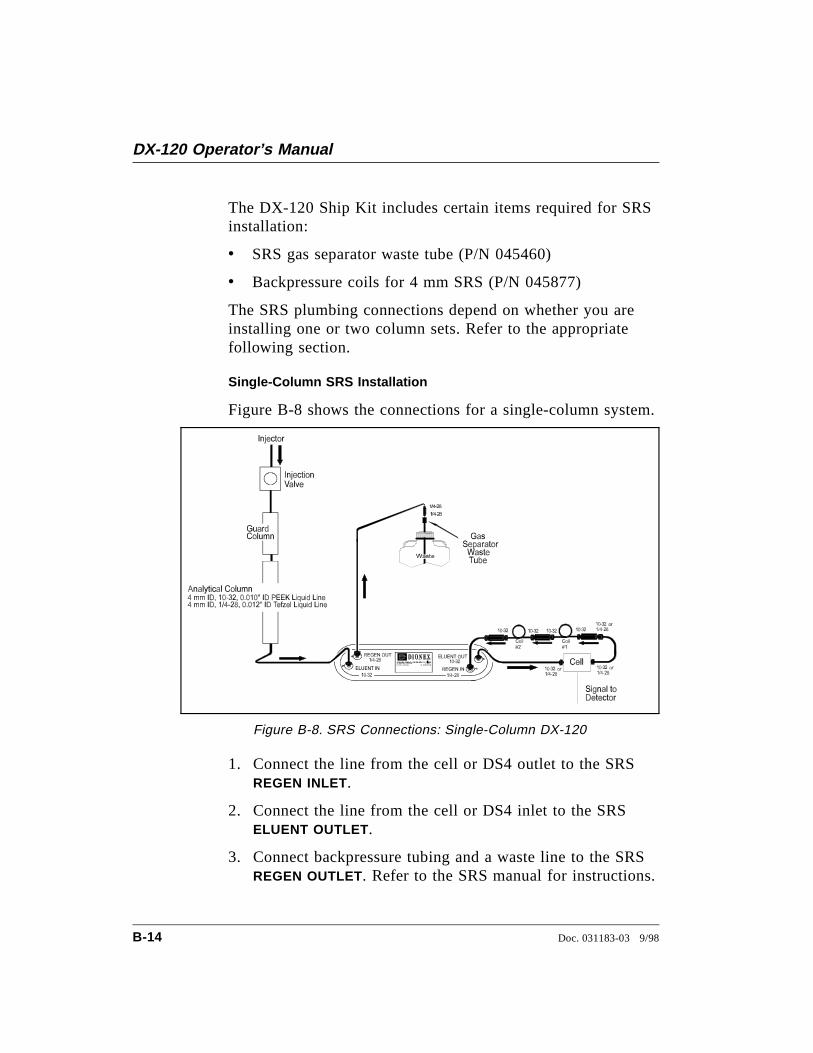
The DX-120 Ship Kit includes certain items required for SRSinstallation:
• SRS gas separator waste tube (P/N 045460)
• Backpressure coils for 4 mm SRS (P/N 045877)
The SRS plumbing connections depend on whether you areinstalling one or two column sets. Refer to the appropriatefollowing section.
Single-Column SRS Installation
Figure B-8 shows the connections for a single-column system.
1. Connect the line from the cell or DS4 outlet to the SRSREGEN INLET.
2. Connect the line from the cell or DS4 inlet to the SRSELUENT OUTLET .
3. Connect backpressure tubing and a waste line to the SRSREGEN OUTLET. Refer to the SRS manual for instructions.
Figure B-8. SRS Connections: Single-Column DX-120
DX-120 Operator’s Manual
B-14 Doc. 031183-03 9/98
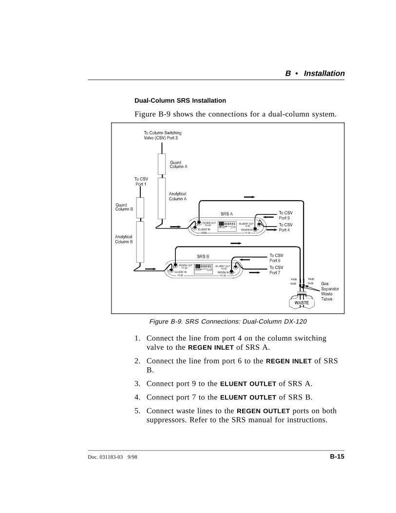
Dual-Column SRS Installation
Figure B-9 shows the connections for a dual-column system.
1. Connect the line from port 4 on the column switchingvalve to the REGEN INLET of SRS A.
2. Connect the line from port 6 to the REGEN INLET of SRSB.
3. Connect port 9 to the ELUENT OUTLET of SRS A.
4. Connect port 7 to the ELUENT OUTLET of SRS B.
5. Connect waste lines to the REGEN OUTLET ports on bothsuppressors. Refer to the SRS manual for instructions.
Figure B-9. SRS Connections: Dual-Column DX-120
B • Installation
Doc. 031183-03 9/98 B-15
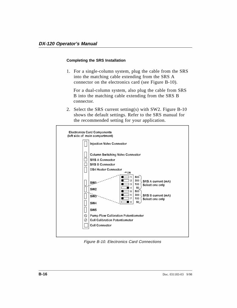
Completing the SRS Installation
1. For a single-column system, plug the cable from the SRSinto the matching cable extending from the SRS Aconnector on the electronics card (see Figure B-10).
For a dual-column system, also plug the cable from SRSB into the matching cable extending from the SRS Bconnector.
2. Select the SRS current setting(s) with SW2. Figure B-10shows the default settings. Refer to the SRS manual forthe recommended setting for your application.
Figure B-10. Electronics Card Connections
DX-120 Operator’s Manual
B-16 Doc. 031183-03 9/98
B.6.3 Column Installation
Before installing the column(s) in the DX-120, refer to thecolumn manual for specialized installation and start-upinstructions.
Column Setup
1. Before installing the separator column, pump deionizedwater through the injection valve at 1.0 to 3.0 mL/min for2 to 5 minutes to clear any air from the liquid lines.Trapped air reduces the column efficiency.
2. Switch the injection valve between the INJECT and LOAD
positions several times. This allows water to flow throughthe sample loop and each valve port.
3. Set the Low Pressure Alarm DIP switch (SW1-8) to off.Set the flow rate to 2.0 mL/min and verify that thepressure through the system, with no columns installed, isless than 690 KPa (100 psi). Reset the Low PressureAlarm switch to on.
4. Stop the pump.
5. Remove the end plugs from the separator column(s) andstore them in a safe place. You must reinstall the endplugs in the column(s) before placing them in storage.
6. If they are not already installed, install the columnmounting clips (P/N 046699) on the component panel.Orient each clip with the larger clasps toward the front ofthe panel; then, squeeze the open ends of the clip togetherand insert them into the square opening. Install two clipsfor the separator column(s) and one for the guardcolumn(s).
NOTEAn arrow on each column indicates the liquid flowdirection. The arrow points toward the column outlet.
B • Installation
Doc. 031183-03 9/98 B-17
7. Orient the guard column with the outlet facing down andsnap the column into its clip. For dual-column systems,snap column A in the back and column B in the front.
8. Orient the separator column with the outlet facing up andsnap the column into its clip. For dual-column systems,snap column A in the back and column B in the front.
The remaining steps depend upon whether you are installingone or two column sets.
Single-Column Set Connections
1. Connect the line from port 3 on the injection valve to theguard column inlet.
2. Connect the guard column outlet to the separator columninlet. Use 0.25-mm (0.010-in) ID tubing (P/N 042690),10-32 fittings (P/N 043275), and ferrules (P/N 043276).
3. For AutoSuppression mode, connect the separator columnoutlet to the SRS ELUENT INLET . For Nonsuppressedmode, connect the separator column outlet to the cell orDS4 inlet. Use 0.25-mm (0.010-in) ID tubing (P/N042690), 10-32 fittings (P/N 043275), and ferrules (P/N043276).
Dual-Column Set Connections
1. Connect the line from port 1 on the column switchingvalve to the inlet of guard column B.
2. Connect the line from port 3 on the column switchingvalve to the inlet of guard column A.
3. Connect the outlet of guard column A to the inlet ofseparator column A. Use 0.25-mm (0.010-in) ID tubing(P/N 042690), 10-32 fittings (P/N 043275), and ferrules(P/N 043276). Repeat for guard and separator columns B.
DX-120 Operator’s Manual
B-18 Doc. 031183-03 9/98
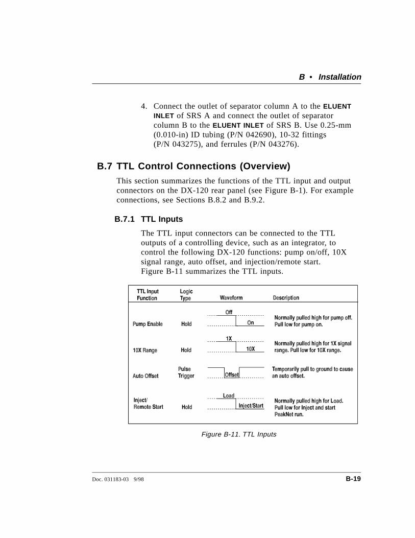
4. Connect the outlet of separator column A to the ELUENTINLET of SRS A and connect the outlet of separatorcolumn B to the ELUENT INLET of SRS B. Use 0.25-mm(0.010-in) ID tubing (P/N 042690), 10-32 fittings(P/N 043275), and ferrules (P/N 043276).
B.7 TTL Control Connections (Overview)This section summarizes the functions of the TTL input and outputconnectors on the DX-120 rear panel (see Figure B-1). For exampleconnections, see Sections B.8.2 and B.9.2.
B.7.1 TTL Inputs
The TTL input connectors can be connected to the TTLoutputs of a controlling device, such as an integrator, tocontrol the following DX-120 functions: pump on/off, 10Xsignal range, auto offset, and injection/remote start.Figure B-11 summarizes the TTL inputs.
Figure B-11. TTL Inputs
B • Installation
Doc. 031183-03 9/98 B-19
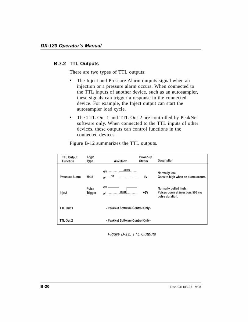
B.7.2 TTL Outputs
There are two types of TTL outputs:
• The Inject and Pressure Alarm outputs signal when aninjection or a pressure alarm occurs. When connected tothe TTL inputs of another device, such as an autosampler,these signals can trigger a response in the connecteddevice. For example, the Inject output can start theautosampler load cycle.
• The TTL Out 1 and TTL Out 2 are controlled by PeakNetsoftware only. When connected to the TTL inputs of otherdevices, these outputs can control functions in theconnected devices.
Figure B-12 summarizes the TTL outputs.
Figure B-12. TTL Outputs
DX-120 Operator’s Manual
B-20 Doc. 031183-03 9/98
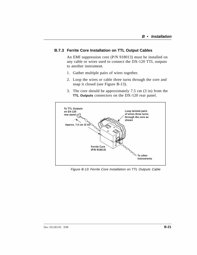
B.7.3 Ferrite Core Installation on TTL Output Cables
An EMI suppression core (P/N 918013) must be installed onany cable or wires used to connect the DX-120 TTL outputsto another instrument.
1. Gather multiple pairs of wires together.
2. Loop the wires or cable three turns through the core andsnap it closed (see Figure B-13).
3. The core should be approximately 7.5 cm (3 in) from theTTL Outputs connectors on the DX-120 rear panel.
Approx. 7.5 cm (3 in )
To otherinstruments
Loo p tw isted pairsof w ires three turnsthrou gh the core asshown
To TTL Out putson DX-120rear panel
Ferrite Core(P/N 918013)
Figure B-13. Ferrite Core Installation on TTL Outputs Cable
B • Installation
Doc. 031183-03 9/98 B-21
B.8 Autosampler Connections (Optional)
B.8.1 Autosampler Outlet Line Connection
1. Disconnect the sample inject line from port 5 on theDX-120 injection valve (see Figure B-20).
2. Route the outlet line from the autosampler through theopening below the injection port on the DX-120 frontdoor (see Figure 2-1). Connect the line to port 5.
B.8.2 AS40 Automated Sampler Connections
This section describes how to connect an AS40 AutomatedSampler to a DX-120 that is connected to a PeakNetworkstation. Figure B-14 illustrates the TTL connections. Ifthe DX-120 is connected to an integrator, see Section B.9.2for the AS40 connections.
1. Locate the Relay Control cable (P/N 047946) suppliedwith the AS40 Automated Sampler. Connect this cable’s10-pin connector to the RELAY CONTROL connector on theAS40 rear panel.
2. Remove the 2-pin connector from the pair of wireslabeled LOAD on the Relay Control cable.
When connecting wires to the green connectors, be carefulnot to allow stray strands of wire to short to the adjoiningterminal on the connector.
3. Locate a green 3-pin connector (P/N 921186) in theDX-120 Ship Kit. Insert the red wire from the LOAD pairinto the last position on the connector and tighten thelocking screw. Insert the ground wire into the firstposition on the connector and tighten.
4. Install an EMI suppression ferrite core on the wires (seeSection B.7.3).
DX-120 Operator’s Manual
B-22 Doc. 031183-03 9/98
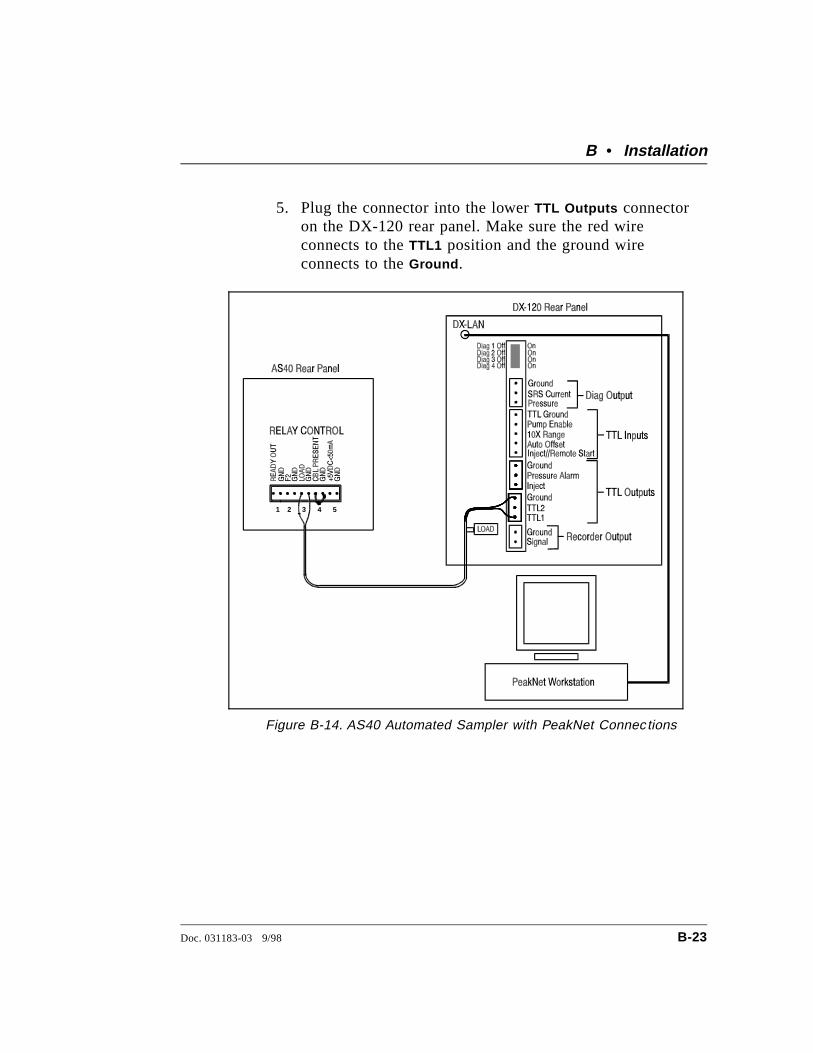
5. Plug the connector into the lower TTL Outputs connectoron the DX-120 rear panel. Make sure the red wireconnects to the TTL1 position and the ground wireconnects to the Ground .
1 2 3 4 5
Figure B-14. AS40 Automated Sampler with PeakNet Connec tions
B • Installation
Doc. 031183-03 9/98 B-23
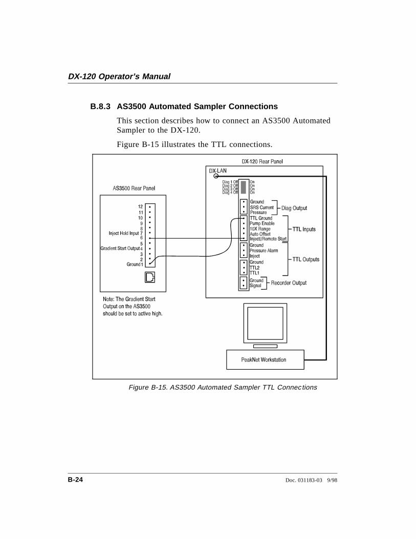
B.8.3 AS3500 Automated Sampler Connections
This section describes how to connect an AS3500 AutomatedSampler to the DX-120.
Figure B-15 illustrates the TTL connections.
Figure B-15. AS3500 Automated Sampler TTL Connec tions
DX-120 Operator’s Manual
B-24 Doc. 031183-03 9/98
1. Locate the green 5-pin connector (P/N 921273) and thetwisted pair of wires (P/N 043598) in the DX-120 ShipKit. Insert the signal wire from the pair into the lastposition on the connector. Use a screwdriver to tighten thelocking screw. Insert the ground wire into the firstposition on the connector and tighten.
When connecting wires to the green connectors, be carefulnot to allow stray strands of wire to short to the adjoiningterminal on the connector.
2. Plug the 5-pin connector into the TTL INPUTS connectoron the DX-120 rear panel. Make sure the signal wireconnects to the Inject position and the ground wire to theTTL Ground .
3. Connect the other end of the signal wire to Pin 6 on theAS3500 rear panel.
B • Installation
Doc. 031183-03 9/98 B-25

Disabling the DX-120 Injection Valve
With the above TTL connections, each time the AS3500sends a remote start output signal to the DX-120 to start aPeakNet run, the DX-120 injection valve automaticallyswitches to the Inject position. If desired, you can disable theDX-120 injection valve.
1. Locate the set of DIP switches above the TTL connectorson the DX-120 rear panel (see Figure B-16).
2. The default position for all these switches is Off.
3. To disable the DX-120 injection valve, use a smallscrewdriver to press switch 2 down (the On position).
Figure B-16. Disabling the DX-120 Injection Valve
DX-120 Operator’s Manual
B-26 Doc. 031183-03 9/98
B.9 Recorder and Integrator Connections (Optional)
B.9.1 Chart Recorder Connections
1. Connect one end of the Recorder Signal Wire assembly(P/N 043598) to the Recorder Output connectors on theDX-120 rear panel (see Figure B-1).
2. Connect the other end to the appropriate input connectorson the chart recorder.
B.9.2 4400 or 4600 Integrator Connections
Recorder Data Transmission
To use the integrator as a recorder with integration functions:
1. Connect one end of the Recorder Signal Wire assembly(P/N 043598) to the Recorder Output connectors on theDX-120 rear panel (see Figure B-1).
2. Connect the other end to the 4400 or 4600 Integratorinput connectors.
Time Functions Automation
To use the integrator for timed control of DX-120 and AS40Automated Sampler functions, install an Automation Cable(P/N 043940), in addition to the Recorder Signal Wireassembly. Figure B-17 illustrates the wire connections.
1. Set the DX-120 to Local control.
2. Connect the Automation Cable’s 36-pin connector to theTIME FUNCTION connector on the rear of the integrator.
3. Connect the Automation Cable’s 10-pin green connector,labeled A1, to the AS40 RELAY CONTROL connector onthe rear of the autosampler.
4. Connect the Automation Cable’s 5-pin green connector,labeled A3, to the DX-120 TTL Input connector.
B • Installation
Doc. 031183-03 9/98 B-27
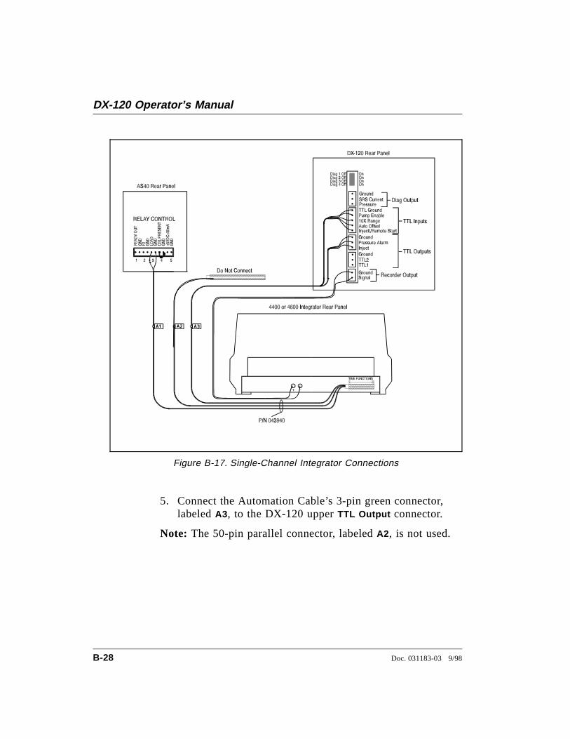
5. Connect the Automation Cable’s 3-pin green connector,labeled A3, to the DX-120 upper TTL Output connector.
Note: The 50-pin parallel connector, labeled A2, is not used.
Figure B-17. Single-Channel Integrator Connections
DX-120 Operator’s Manual
B-28 Doc. 031183-03 9/98
B.10 Configuration DIP Switch SettingsThe DIP switches on the left side of the main compartment setvarious DX-120 operating parameters. The factory default settingsare appropriate for most applications. After reviewing the settingslisted in Figure B-18, make any changes required for your system.
NOTEThe DIP switch labeled DIAGNOSTIC TESTS on the rear panelis for service procedures only. Do not change any of its settingsunless directed to do so by a Dionex Service representative. Forroutine operation, all settings are off.
B • Installation
Doc. 031183-03 9/98 B-29
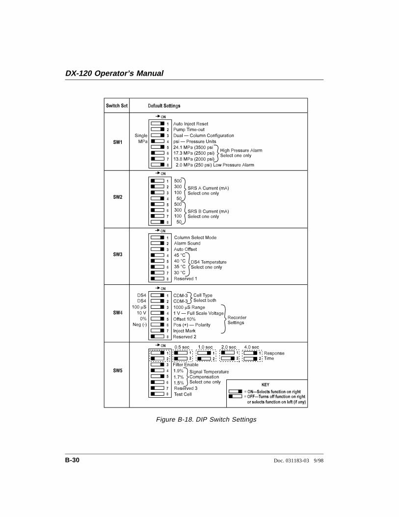
Figure B-18. DIP Switch Settings
DX-120 Operator’s Manual
B-30 Doc. 031183-03 9/98
DIP Switch Function Description
Auto Inject Reset(SW1-1)
When on, the injection valve automaticallyreturns to the Load position 60 seconds after itis switched to the Inject position.
Pump Time-out(SW1-2)
When on, if the DX-120 is idle for 90 minutes,the pump flow is reduced to 1/20th of itscurrent rate. The LED on the Pump buttonflashes when the pump flow is reduced. Pressany button to resume the last selected flow rate.
Column Configuration (SW1-3)
Selects the column configuration: dual (on) orsingle (off).
Pressure Units(SW1-4)
Selects the pressure units (psi or MPa) shownon the screen.
High Pressure Alarm(SW1-5, 6, 7)
Selects at what pressure the high pressurealarm occurs.
Low Pressure Alarm(SW1-8)
Enables an alarm when a low pressurecondition (2.0 MPa or less) occurs.
SRS A Current(SW2-1, 2, 3, 4)
Selects the operating current for the SRS (orSRS A in a dual-column system).
SRS B Current(SW2-5, 6, 7, 8)
Selects the operating current for SRS B in adual-column system.
Column Select Mode(SW3-1)
For dual-column configurations (SW1-3 on).When on, selects the column select mode (seeSection 2.2.1). When off, selects the eluentselect mode (see Section 2.2.2).
Alarm Sound(SW3-2)
Enables or disables the alarm tone.
Auto Offset(SW3-3)
When on, an auto offset is performed wheninjection occurs.
DS4 Temperature(SW3-4, 5, 6, 7)
Selects the DS4 operating temperature. Select atemperature at least 5 °C above the highestexpected ambient temperature.
B • Installation
Doc. 031183-03 9/98 B-31
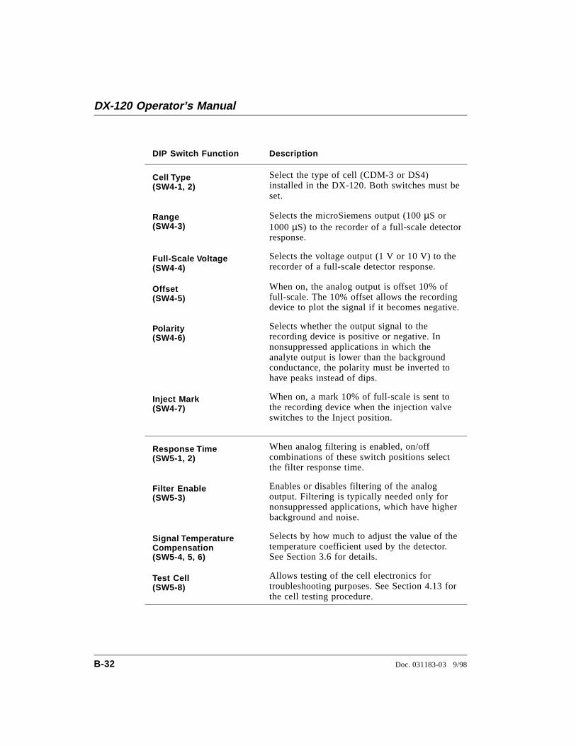
DIP Switch Function Description
Cell Type(SW4-1, 2)
Select the type of cell (CDM-3 or DS4)installed in the DX-120. Both switches must beset.
Range(SW4-3)
Selects the microSiemens output (100 µS or1000 µS) to the recorder of a full-scale detectorresponse.
Full-Scale Voltage(SW4-4)
Selects the voltage output (1 V or 10 V) to therecorder of a full-scale detector response.
Offset(SW4-5)
When on, the analog output is offset 10% offull-scale. The 10% offset allows the recordingdevice to plot the signal if it becomes negative.
Polarity(SW4-6)
Selects whether the output signal to therecording device is positive or negative. Innonsuppressed applications in which theanalyte output is lower than the backgroundconductance, the polarity must be inverted tohave peaks instead of dips.
Inject Mark(SW4-7)
When on, a mark 10% of full-scale is sent tothe recording device when the injection valveswitches to the Inject position.
Response Time(SW5-1, 2)
When analog filtering is enabled, on/offcombinations of these switch positions selectthe filter response time.
Filter Enable(SW5-3)
Enables or disables filtering of the analogoutput. Filtering is typically needed only fornonsuppressed applications, which have higherbackground and noise.
Signal TemperatureCompensation(SW5-4, 5, 6)
Selects by how much to adjust the value of thetemperature coefficient used by the detector.See Section 3.6 for details.
Test Cell(SW5-8)
Allows testing of the cell electronics fortroubleshooting purposes. See Section 4.13 forthe cell testing procedure.
DX-120 Operator’s Manual
B-32 Doc. 031183-03 9/98
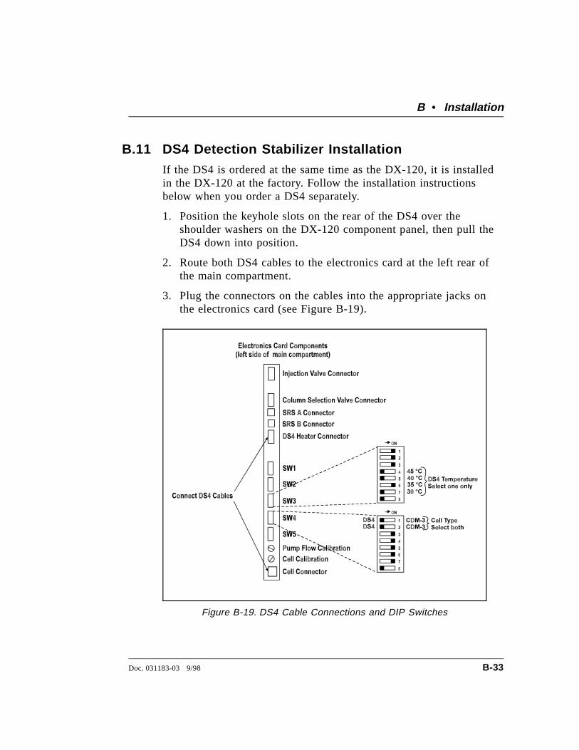
B.11 DS4 Detection Stabilizer InstallationIf the DS4 is ordered at the same time as the DX-120, it is installedin the DX-120 at the factory. Follow the installation instructionsbelow when you order a DS4 separately.
1. Position the keyhole slots on the rear of the DS4 over theshoulder washers on the DX-120 component panel, then pull theDS4 down into position.
2. Route both DS4 cables to the electronics card at the left rear ofthe main compartment.
3. Plug the connectors on the cables into the appropriate jacks onthe electronics card (see Figure B-19).
Figure B-19. DS4 Cable Connections and DIP Switches
B • Installation
Doc. 031183-03 9/98 B-33
4. For single-column systems, connect the SRS ELUENT OUT portto the DS4 inlet (AutoSuppression Recycle mode) or to thecolumn outlet (Nonsuppressed mode), using 0.25-mm (0.010-in)ID tubing (P/N042690), 10-32 fittings (P/N043275), and ferrules(P/N 043276).
For dual-column systems, connect the line from port 8 on thecolumn switching valve to the DS4 inlet.
5. Connect the outlet of the DS4 (the 10-32 coupler) to either theSRS REGEN IN port (for AutoSuppression Recycle mode) or tothe backpressure line leading to waste (for Nonsuppressed mode).
6. Direct the DS4 spill/overflow tubing to the spill tray at thebottom front of the DX-120.
7. Select a DS4 temperature set point (SW3-4, 5, 6, or 7) (seeFigure B-19). Select a temperature at least 5 °C above thehighest expected ambient temperature.
8. Set the Cell Type DIP switches (SW4-1, 2) to the off (DS4)position (see Figure B-19).
DX-120 Operator’s Manual
B-34 Doc. 031183-03 9/98
B.12 CDM-3 Cell InstallationIf the CDM-3 cell is ordered at the same time as the DX-120, it isinstalled in the DX-120 at the factory. Follow the installationinstructions below when you order a CDM-3 separately.
1. Orient the CDM-3 with its mounting bracket to the left and alignthe screw holes on the bracket with the mounting holes on thecomponent panel (see Figure 2-4).
2. Secure the bracket to the component panel with the two Phillipsscrews supplied with the cell and bracket.
3. Route the cell cable to the electronics card at the left rear of themain compartment and plug the cable connector into the CellConnector jack on the card (see Figure B-19).
4. For single-column systems, connect the SRS ELUENT OUT portto the cell inlet (AutoSuppression Recycle mode) or to thecolumn outlet (Nonsuppressed mode), using 0.25-mm (0.010-in)ID tubing (P/N042690), 10-32 fittings (P/N043275), and ferrules(P/N 043276).
For dual-column systems, connect the line from port 8 on thecolumn switching valve to the cell inlet.
5. Connect the cell outlet (the 10-32 coupler) to either the SRSREGEN IN port (for AutoSuppression Recycle mode) or to thebackpressure line leading to waste (for Nonsuppressed mode).
6. Set the Cell Type DIP switches (SW4-1, 2) to the on (CDM-3)position (see Figure B-19).
B • Installation
Doc. 031183-03 9/98 B-35
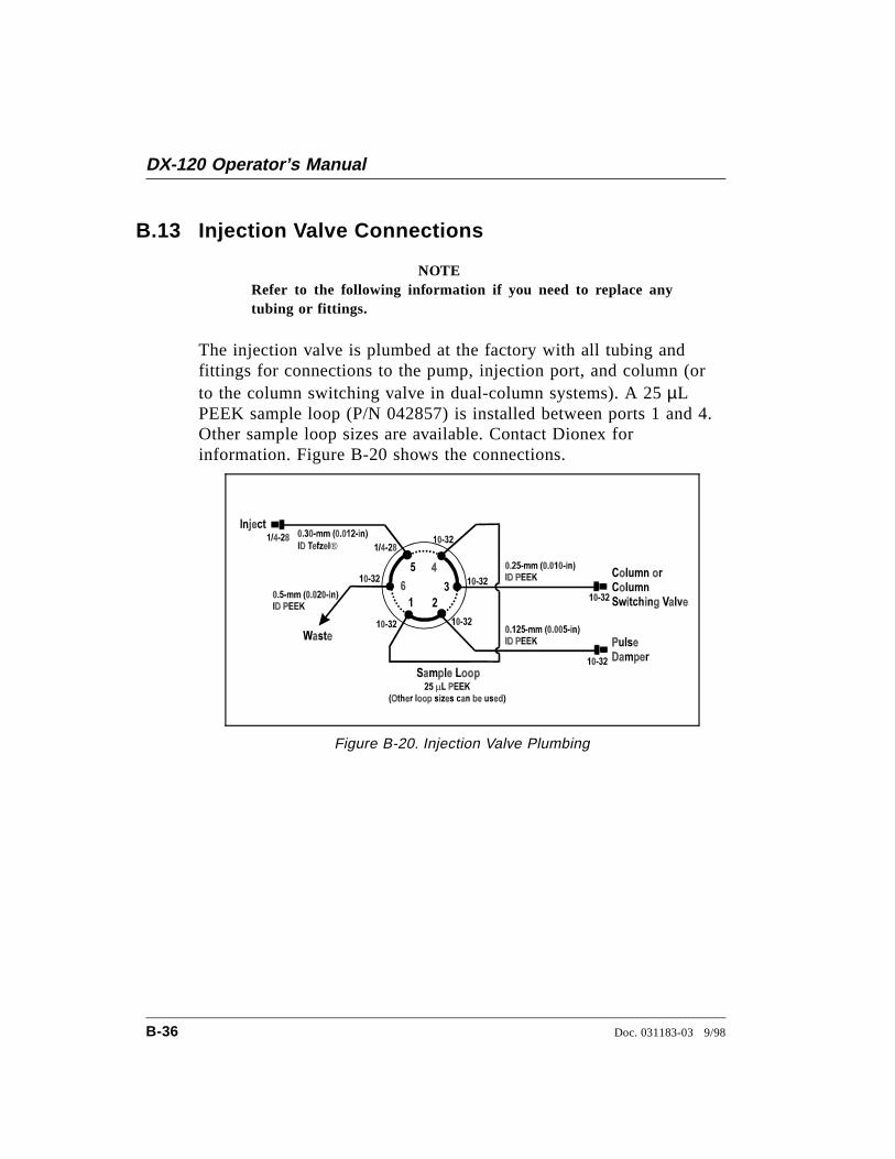
B.13 Injection Valve Connections
NOTERefer to the following information if you need to replace anytubing or fittings.
The injection valve is plumbed at the factory with all tubing andfittings for connections to the pump, injection port, and column (orto the column switching valve in dual-column systems). A 25 µLPEEK sample loop (P/N 042857) is installed between ports 1 and 4.Other sample loop sizes are available. Contact Dionex forinformation. Figure B-20 shows the connections.
Figure B-20. Injection Valve Plumbing
DX-120 Operator’s Manual
B-36 Doc. 031183-03 9/98
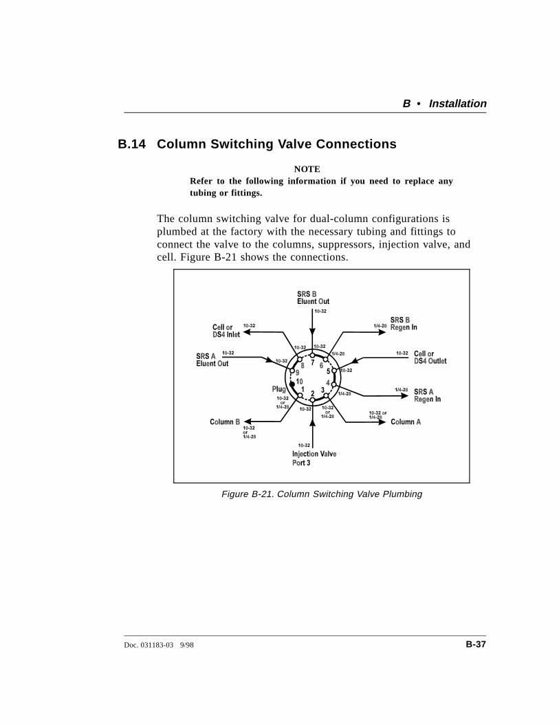
B.14 Column Switching Valve Connections
NOTERefer to the following information if you need to replace anytubing or fittings.
The column switching valve for dual-column configurations isplumbed at the factory with the necessary tubing and fittings toconnect the valve to the columns, suppressors, injection valve, andcell. Figure B-21 shows the connections.
Figure B-21. Column Switching Valve Plumbing
B • Installation
Doc. 031183-03 9/98 B-37
B.15 DX-LAN Card Installation (Optional)For the DX-120 to communicate with PeakNet software, a DX-LANinterface card (P/N 050225) must be installed in the DX-120. If youorder a DX-120 with the DX-LAN option, the card is installed at thefactory. Follow the installation procedure below if you order aDX-LAN at a later time.
STATIC—The DX-120 electronics are not user-serviceableand the DX-LAN interface card should be installed byqualified personnel only. Observe standard anti-staticprocedures when installing the interface card or handlingthe electronics card.
To prevent damage to the DX-120, turn off the main powerand unplug the power cord before installing the interfacecard. Turning off only the front panel power switch is notsufficient.
1. Disconnect all cables from the electronics card at the leftof the main compartment (see Figure 2-2).
2. Remove the card’s holding screw located above the DIPswitches.
3. Disconnect the gas supply line from the rear panel andunplug any TTL connectors.
4. Remove the screws from the rear panel and remove therear panel from the DX-120. Remove the screws from theelectronics card front plate (see Figure B-22).
5. Inside the DX-120 rear compartment, disconnect allcables from the electronics card. Note the connectorlocation for each cable.
6. Pull out the electronics card far enough to allow access tothe DX-LAN connector on the top edge of the card (seeFigure B-23).
DX-120 Operator’s Manual
B-38 Doc. 031183-03 9/98
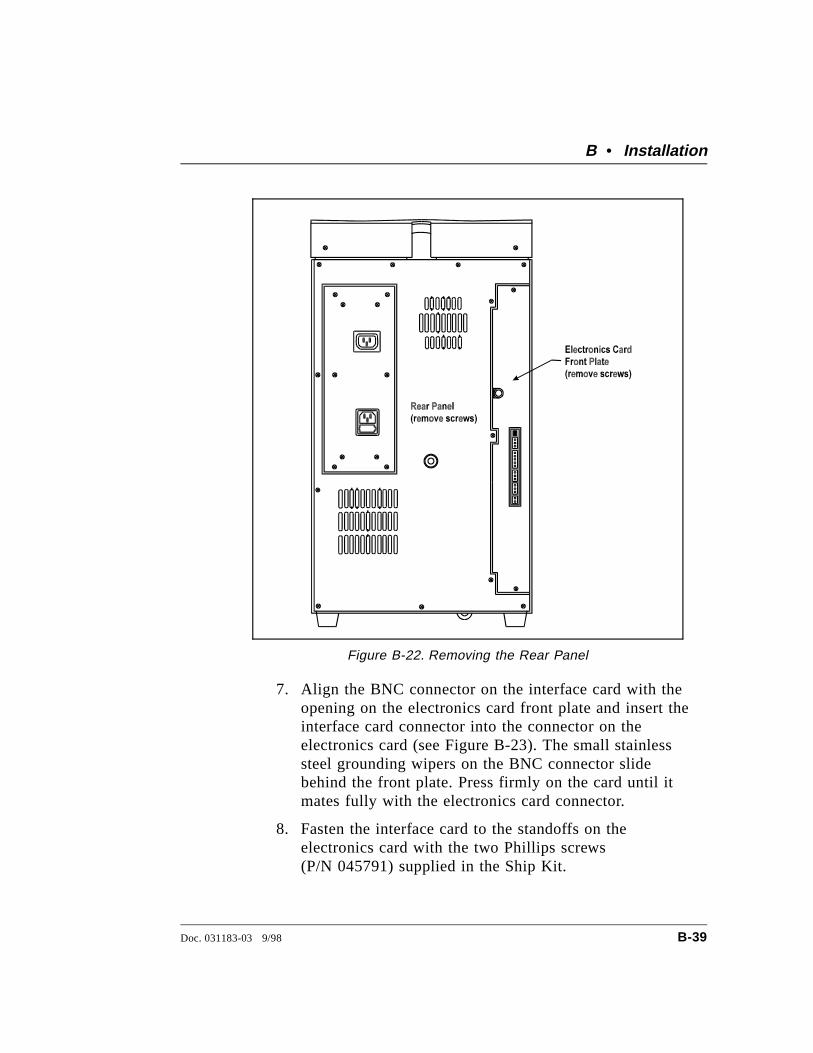
7. Align the BNC connector on the interface card with theopening on the electronics card front plate and insert theinterface card connector into the connector on theelectronics card (see Figure B-23). The small stainlesssteel grounding wipers on the BNC connector slidebehind the front plate. Press firmly on the card until itmates fully with the electronics card connector.
8. Fasten the interface card to the standoffs on theelectronics card with the two Phillips screws(P/N 045791) supplied in the Ship Kit.
Figure B-22. Removing the Rear Panel
B • Installation
Doc. 031183-03 9/98 B-39
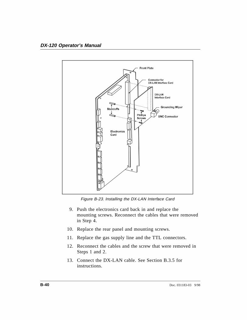
9. Push the electronics card back in and replace themounting screws. Reconnect the cables that were removedin Step 4.
10. Replace the rear panel and mounting screws.
11. Replace the gas supply line and the TTL connectors.
12. Reconnect the cables and the screw that were removed inSteps 1 and 2.
13. Connect the DX-LAN cable. See Section B.3.5 forinstructions.
Figure B-23. Installing the DX-LAN Interface Card
DX-120 Operator’s Manual
B-40 Doc. 031183-03 9/98
C • Integrator Programming
A Dionex 4400 or 4600 Integrator can collect and integrate datafrom the DX-120. If you install an Automation Cable (P/N 043940),the integrator can also control the following functions:
• Pump on/off
• Injection valve position
• Auto offset
• 10X range
• Start the AS40 Automated Sampler load cycle (if installed)
See Section B.9.2 for instructions on connecting the data signalwires and Automation Cable from the DX-120 to the integrator and(optionally) an autosampler.
Refer to the 4440 or 4600 Integrator User’s Guide for initialinstallation and setup of the integrator. After setup, use theinstructions in this appendix to configure the integrator to operatethe DX-120 and the optional autosampler.
C.1 Integrator Power-up ConfigurationAt power-up, the integrator performs various self-diagnostic tests,according to the options purchased with the integrator. Refer to theintegrator user’s guide for details.
After the diagnostic tests are completed, define the integratorparameters required for correct DX-120 data collection. Aftersetting up the integrator, leave the power on. If you turn off thepower, the entered parameters are lost.
1. Press the LCD STATUS key. The LCD displays several parameters:
FI=1 indicates that you are using File 1.CS=1 indicates that the chart speed is 1 cm/min.ATTEN=1 indicates that the recorder response is 1 mV full-scale.
Doc. 031183-03 9/98 C-1
2. Press the PRINT FILE key. Several file parameters will be printed.PW stands for peak width; PT stands for peak threshold.
3. The following parameters enable the integrator to operate withthe DX-120.
a. Press the CHART SPEED key and enter 0.5 (=0.5 cm/min).
b. Press the ATTEN key and enter 1024 (=1024 mV full-scale).
c. Type in and enter PT=1000 (a representative peak thresholdfor 1 V signal).
C.2 Setting OffsetsThe default signal offset for the DX-120 is 10%. This is set with aDIP switch (SW4-4).
The recorder offset for the integrator is determined by the OF value.Dionex recommends that you use the DX-120 factory default settingof 10%, and enter OF=0 for the integrator offset.
C.3 Area Percent ModeAfter the offsets have been entered, the integrator is ready to operatein the area percent mode. This is a simple report format that recordsand integrates peaks from the DX-120 and then reports retentiontime and peak area.
1. To begin integration, press INJ/END A as the sample is beinginjected.
2. When all of the sample peaks have eluted, press INJ/END A againto stop integration and print the report. Use the retention timesfrom this analysis when setting up the component table forautomated operation (see Section C.4).
DX-120 Operator’s Manual
C-2 Doc. 031183-03 9/98
C.4 Using DIALOG to Create a MethodOnce the application is running on the DX-120, you can create anintegrator Method for peak identification, calibration, and reporting.Time Functions, defined in the Method, provide control of DX-120and AS40 Automated Sampler functions.
Refer to Section 3, “Operation Overview,” and Section 8, “TimeFunctions,” in the 4400/4600 manual for details about usingDIALOG and Time Functions.
C.4.1 Time Functions
When a DX-120 Automation Cable is installed, integratorTime Function (TFN) commands are assigned to thefollowing DX-120/AS40 functions:
Time Function(TFN) Command
Value DX-120/AS40 Function
T3 0 AS40 Sampler Ready
T3 1 AS40 Sampler Start Load
T4 0 Detector Range Normal
T4 1 Detector Range 10X
T5 0 Auto Offset Off
T5 1 Auto Offset On
T6 0 Injection Valve Load
T6 1 Injection Valve Inject
T7 0 Pump Off
T7 1 Pump On
At power-up, the Time Function values are 0. This isappropriate for functions T3 through T6. Before running aMethod, the T7 Time Function, which controls the pump,must be set to 1 to turn on the pump. Press the TFN key onthe integrator and enter T7=1.
C • Integrator Programming
Doc. 031183-03 9/98 C-3
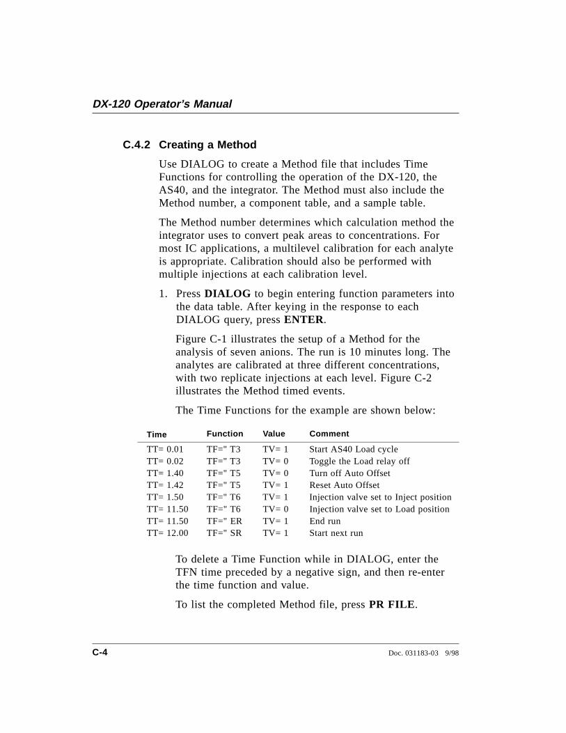
C.4.2 Creating a Method
Use DIALOG to create a Method file that includes TimeFunctions for controlling the operation of the DX-120, theAS40, and the integrator. The Method must also include theMethod number, a component table, and a sample table.
The Method number determines which calculation method theintegrator uses to convert peak areas to concentrations. Formost IC applications, a multilevel calibration for each analyteis appropriate. Calibration should also be performed withmultiple injections at each calibration level.
1. Press DIALOG to begin entering function parameters intothe data table. After keying in the response to eachDIALOG query, press ENTER.
Figure C-1 illustrates the setup of a Method for theanalysis of seven anions. The run is 10 minutes long. Theanalytes are calibrated at three different concentrations,with two replicate injections at each level. Figure C-2illustrates the Method timed events.
The Time Functions for the example are shown below:
Time Function Value Comment
TT= 0.01 TF=" T3 TV= 1 Start AS40 Load cycleTT= 0.02 TF=" T3 TV= 0 Toggle the Load relay offTT= 1.40 TF=" T5 TV= 0 Turn off Auto OffsetTT= 1.42 TF=" T5 TV= 1 Reset Auto OffsetTT= 1.50 TF=" T6 TV= 1 Injection valve set to Inject positionTT= 11.50 TF=" T6 TV= 0 Injection valve set to Load positionTT= 11.50 TF=" ER TV= 1 End runTT= 12.00 TF=" SR TV= 1 Start next run
To delete a Time Function while in DIALOG, enter theTFN time preceded by a negative sign, and then re-enterthe time function and value.
To list the completed Method file, press PR FILE .
DX-120 Operator’s Manual
C-4 Doc. 031183-03 9/98

FI = 1 . FE= 1 . MN= 0 .PRESS ' ENTER' TO SKI P ENTRYENABLE BASELI NE DRAWI NG? [ Y/ N] ( N)STORAGE MENU? [ Y/ N] ( N)
FUNCTI ON NUMBER [ 0 - 10 ] ( 0 )
FI LE NAME ( ) = " ANI ONSTI ME FUNCTI ON VALUETT= 0 . 01 TF=" T3 TV=1TT= 0 . 02 TF=" T3 TV=0TT= 1 . 40 TF=" T5 TV=0TT= 1 . 41 TF=" T5 TV=1TT= 1 . 50 TF=" T6 TV=1TT= 11. 50 TF=" T6 TV=0TT= 11. 50 TE=" ER TV=1TT= 12. 00 TE=" SR TV=1TT=
METHOD NUMBER [ 0 , 1 , 2, 5 ] ( O) MN=5I F NV=0 THEN NO CALI BI F NV=1 THEN NORMAL CALI BI F NV>1 THEN MULTI - LEVEL CALI BNUMBER OF LEVELS [ 0 - 26 ] ( 0 . ) NV= 3I NJ ECTI ONS/ LEVEL ( 1 ) = 2TOTAL CALI B I NJ ECTI ONS, RC= 6L I NEAR[ 1 ] OR NONLI NEAR[ 2 ] ( ) LS= 1COMPONENT TABLE. . .RET TI ME NAMERT= 1 . 30 CN=" FRT= 1 . 70 CN=" ClRT= 2 . 00 CN=" NO2RT= 2 . 50 CN=" BrRT= 3 . 40 CN=" NO3RT= 7 . 90 CN=" SO4RT= 8 . 80 CN=" HPO4RT=EXPECTED CONC [ Y/ N] ( N)
RRT REF PEAK: RP( I ) = 1 . 7RRT REF PEAK: RP( I ) =MULTI LEVEL CALI B VALUES:RETENTI ON TI MES:
RT( 1 ) = 1 . 3 ( 2 ) = 1 . 7 ( 3) = 2CONCENTRATI ONS:
VA( 1 ) = 1 VA( 2 ) = 2 VA( 3 ) = 2VB( 1 ) = 2 . 5 VA( 2 ) = 5 VA( 3 ) = 5VC( 1 ) = 5 VA( 2 ) = 10 VA( 3 ) = 10
RETENTI ON TI MES:RT( 4 ) = 2 . 5 ( 5 ) = 3 . 4 ( 6) = 3 . 8
CONCENTRATI ONS:VA( 4 ) = 2 VA( 5 ) = 2 VA( 6 ) = 2VB( 4 ) = 5 VA( 5 ) = 5 VA( 6 ) = 5VC( 4 ) = 10 VA( 5 ) = 10 VA( 6 ) = 10
RETENTI ON TI MES:RT( 7 ) = 7 . 9 ( 7 ) = 8 . 8
CONCENTRATI ONS:VA( 7 ) = 2 VA( 8) = 2VB( 7 ) = 5 VA( 8 ) = 5VC( 7 ) = 10 VA( 8 ) = 10
SAMPLE TABLE. . .ANALYST ( ) AN=" DI ONEXI NJ ECTI ONS/ SAMPLE [ 0- 254 ] ( 0 . ) RA=SAMPLES BETWEEN CALI B [ 0 - 254] ( 0 . ) C1=CONC UNI TS ( ) CU=" PPMSAM I X NAME SAM AMT SCALESI =END OF DI ALOG
1
2
3
4
55
4
3
2
1 Enter Time Functions
Enter the M ethod number
Enter the retention timeand name of each component
Enter the retention timeof a reference peak
Enter the concentrations forthe cal ibration levels for eachcomponent. For F, enter 1, 2.5, and 5.For al l others, enter 2, 5, and 10.
Figure C-1. DIALOG Entry Example A
C • Integrator Programming
Doc. 031183-03 9/98 C-5
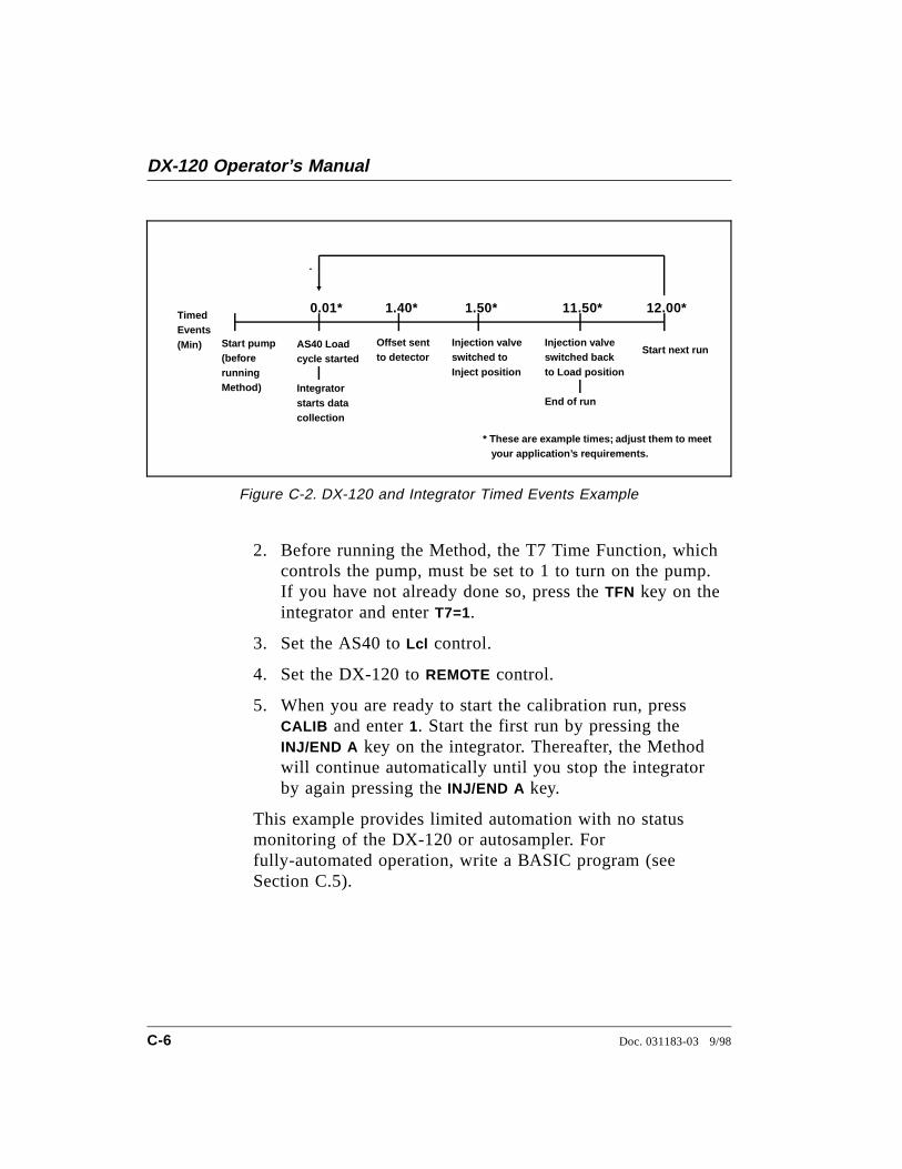
2. Before running the Method, the T7 Time Function, whichcontrols the pump, must be set to 1 to turn on the pump.If you have not already done so, press the TFN key on theintegrator and enter T7=1.
3. Set the AS40 to Lcl control.
4. Set the DX-120 to REMOTE control.
5. When you are ready to start the calibration run, pressCALIB and enter 1. Start the first run by pressing theINJ/END A key on the integrator. Thereafter, the Methodwill continue automatically until you stop the integratorby again pressing the INJ/END A key.
This example provides limited automation with no statusmonitoring of the DX-120 or autosampler. Forfully-automated operation, write a BASIC program (seeSection C.5).
11.50*
Offset sentto detector
Injection valveswitched toInject position
TimedEvents(Min)
1.50*
Start next run
1.40*0.01*
AS40 Loadcycle started
Integratorstarts datacollection
* These are example times; adjust them to meet your application’s requirements.
12.00*
Start pump(beforerunningMethod)
Injection valveswitched backto Load position
End of run
Figure C-2. DX-120 and Integrator Timed Events Example
DX-120 Operator’s Manual
C-6 Doc. 031183-03 9/98
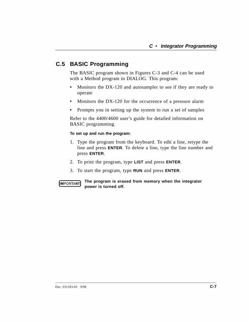
C.5 BASIC ProgrammingThe BASIC program shown in Figures C-3 and C-4 can be usedwith a Method program in DIALOG. This program:
• Monitors the DX-120 and autosampler to see if they are ready tooperate
• Monitors the DX-120 for the occurrence of a pressure alarm
• Prompts you in setting up the system to run a set of samples
Refer to the 4400/4600 user’s guide for detailed information onBASIC programming.
To set up and run the program:
1. Type the program from the keyboard. To edit a line, retype theline and press ENTER. To delete a line, type the line number andpress ENTER.
2. To print the program, type LIST and press ENTER.
3. To start the program, type RUN and press ENTER.
The program is erased from memory when the integratorpower is turned off.
C • Integrator Programming
Doc. 031183-03 9/98 C-7
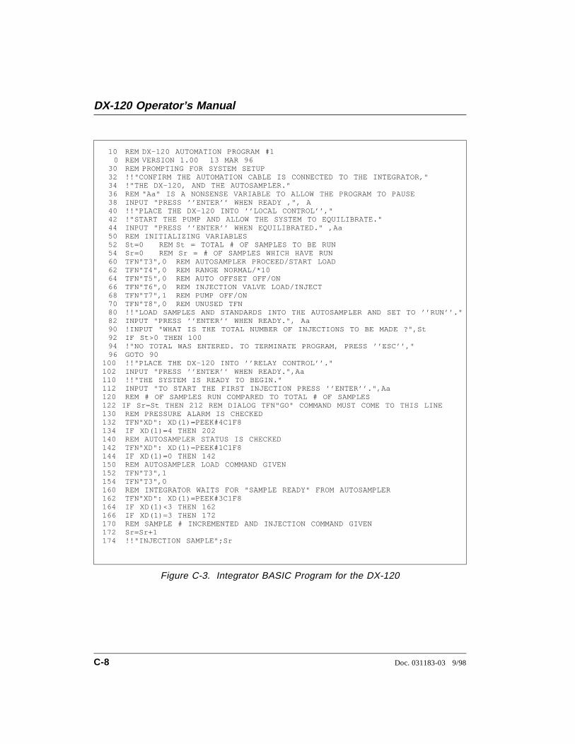
10 REM DX-120 AUTOMATION PROGRAM #1 0 REM VERSION 1.00 13 MAR 9630 REM PROMPTING FOR SYSTEM SETUP32 !!"CONFIRM THE AUTOMATION CABLE IS CONNECTED TO THE INTEGRATOR,"34 !"THE DX-120, AND THE AUTOSAMPLER."36 REM "Aa" IS A NONSENSE VARIABLE TO ALLOW THE PROGRAM TO PAUSE38 INPUT "PRESS ’’ENTER’’ WHEN READY ,", A40 !!"PLACE THE DX-120 INTO ’’LOCAL CONTROL’’,"42 !"START THE PUMP AND ALLOW THE SYSTEM TO EQUILIBRATE."44 INPUT "PRESS ’’ENTER’’ WHEN EQUILIBRATED." ,Aa50 REM INITIALIZING VARIABLES52 St=0 REM St = TOTAL # OF SAMPLES TO BE RUN54 Sr=0 REM Sr = # OF SAMPLES WHICH HAVE RUN60 TFN"T3",0 REM AUTOSAMPLER PROCEED/START LOAD62 TFN"T4",0 REM RANGE NORMAL/*1064 TFN"T5",0 REM AUTO OFFSET OFF/ON66 TFN"T6",0 REM INJECTION VALVE LOAD/INJECT68 TFN"T7",1 REM PUMP OFF/ON70 TFN"T8",0 REM UNUSED TFN80 !!"LOAD SAMPLES AND STANDARDS INTO THE AUTOSAMPLER AND SET TO ’’RUN’’."82 INPUT "PRESS ’’ENTER’’ WHEN READY.", Aa90 !INPUT "WHAT IS THE TOTAL NUMBER OF INJECTIONS TO BE MADE ?",St92 IF St>0 THEN 10094 !"NO TOTAL WAS ENTERED. TO TERMINATE PROGRAM, PRESS ’’ESC’’,"96 GOTO 90
100 !!"PLACE THE DX-120 INTO ’’RELAY CONTROL’’." 102 INPUT "PRESS ’’ENTER’’ WHEN READY.",Aa 110 !!"THE SYSTEM IS READY TO BEGIN." 112 INPUT "TO START THE FIRST INJECTION PRESS ’’ENTER’’.",Aa 120 REM # OF SAMPLES RUN COMPARED TO TOTAL # OF SAMPLES 122 IF Sr=St THEN 212 REM DIALOG TFN"GO" COMMAND MUST COME TO THIS LINE 130 REM PRESSURE ALARM IS CHECKED 132 TFN"XD": XD(1)=PEEK#4C1F8 134 IF XD(1)=4 THEN 202 140 REM AUTOSAMPLER STATUS IS CHECKED 142 TFN"XD": XD(1)=PEEK#1C1F8 144 IF XD(1)=0 THEN 142 150 REM AUTOSAMPLER LOAD COMMAND GIVEN 152 TFN"T3",1 154 TFN"T3",0 160 REM INTEGRATOR WAITS FOR "SAMPLE READY" FROM AUTOSAMPLER 162 TFN"XD": XD(1)=PEEK#3C1F8 164 IF XD(1)<3 THEN 162 166 IF XD(1)=3 THEN 172 170 REM SAMPLE # INCREMENTED AND INJECTION COMMAND GIVEN 172 Sr=Sr+1 174 !!"INJECTION SAMPLE";Sr
Figure C-3. Integrator BASIC Program for the DX-120
DX-120 Operator’s Manual
C-8 Doc. 031183-03 9/98
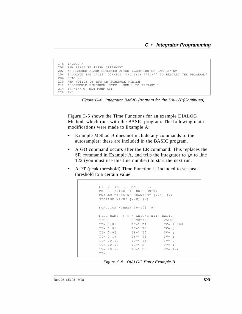
Figure C-5 shows the Time Functions for an example DIALOGMethod, which runs with the BASIC program. The following mainmodifications were made to Example A:
• Example Method B does not include any commands to theautosampler; these are included in the BASIC program.
• A GO command occurs after the ER command. This replaces theSR command in Example A, and tells the integrator to go to line122 (you must use this line number) to start the next run.
• A PT (peak threshold) Time Function is included to set peakthreshold to a certain value.
176 INJECT A 200 REM PRESSURE ALARM STATEMENT 202 !"PRESSURE ALARM DETECTED AFTER INJECTION OF SAMPLE";Sr 204 !"LOCATE THE CAUSE, CORRECT, AND TYPE ’’RUN’’ TO RESTART THE PROGRAM." 206 GOTO 220 210 REM NOTICE OF RUN OR SCHEDULE FINISH 212 !"SCHEDULE FINISHED. TYPE ’’RUN’’ TO RESTART." 214 TFN"T7",0 REM PUMP OFF 220 END
Figure C-4. Integrator BASIC Program for the DX-120 (Continued)
FI= 1. FE= 1. MN= 0.
PRESS 'ENTER' TO SKIP ENTRY
ENABLE BASELINE DRAWING? [Y/N] (N)
STORAGE MENU? [Y/N] (N)
FUNCTION NUMBER [0-10] (0)
FILE NAME () = " ANIONS WITH BASIC
TIME FUNCTION VALUE
TT= 0.01 TF=" PT TV= 10000
TT= 0.01 TF=" T5 TV=
1TT= 0.02 TF=" T5 TV=0
TT= 0.10 TF=" T6 TV= 1
TT= 10.10 TF=" T6 TV= 0
TT= 10.10 TE=" ER TV= 1
TT= 10.60 TE=" GO TV= 122
TT=
Figure C-5. DIALOG Entry Example B
C • Integrator Programming
Doc. 031183-03 9/98 C-9

DX-120 Operator’s Manual
C-10 Doc. 031183-03 9/98
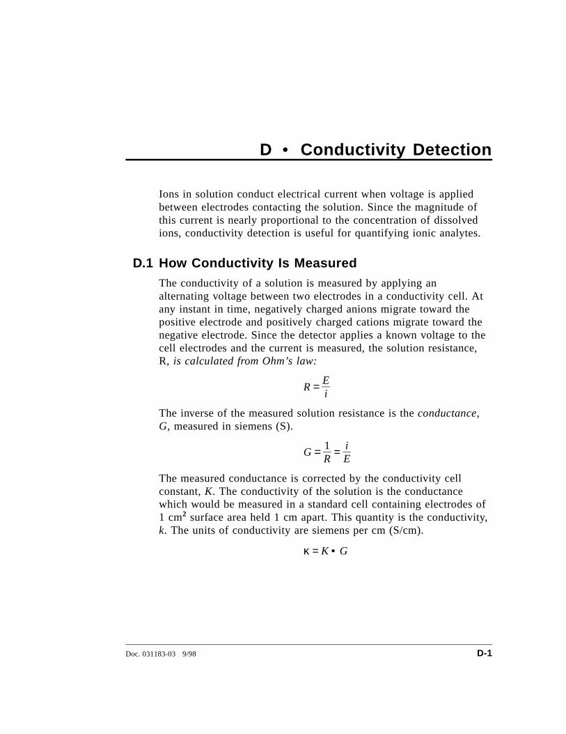
D • Conductivity Detection
Ions in solution conduct electrical current when voltage is appliedbetween electrodes contacting the solution. Since the magnitude ofthis current is nearly proportional to the concentration of dissolvedions, conductivity detection is useful for quantifying ionic analytes.
D.1 How Conductivity Is MeasuredThe conductivity of a solution is measured by applying analternating voltage between two electrodes in a conductivity cell. Atany instant in time, negatively charged anions migrate toward thepositive electrode and positively charged cations migrate toward thenegative electrode. Since the detector applies a known voltage to thecell electrodes and the current is measured, the solution resistance,R, is calculated from Ohm’s law:
R = Ei
The inverse of the measured solution resistance is the conductance,G, measured in siemens (S).
G = 1R
= iE
The measured conductance is corrected by the conductivity cellconstant, K. The conductivity of the solution is the conductancewhich would be measured in a standard cell containing electrodes of1 cm2 surface area held 1 cm apart. This quantity is the conductivity,k. The units of conductivity are siemens per cm (S/cm).
κ = K • G
Doc. 031183-03 9/98 D-1
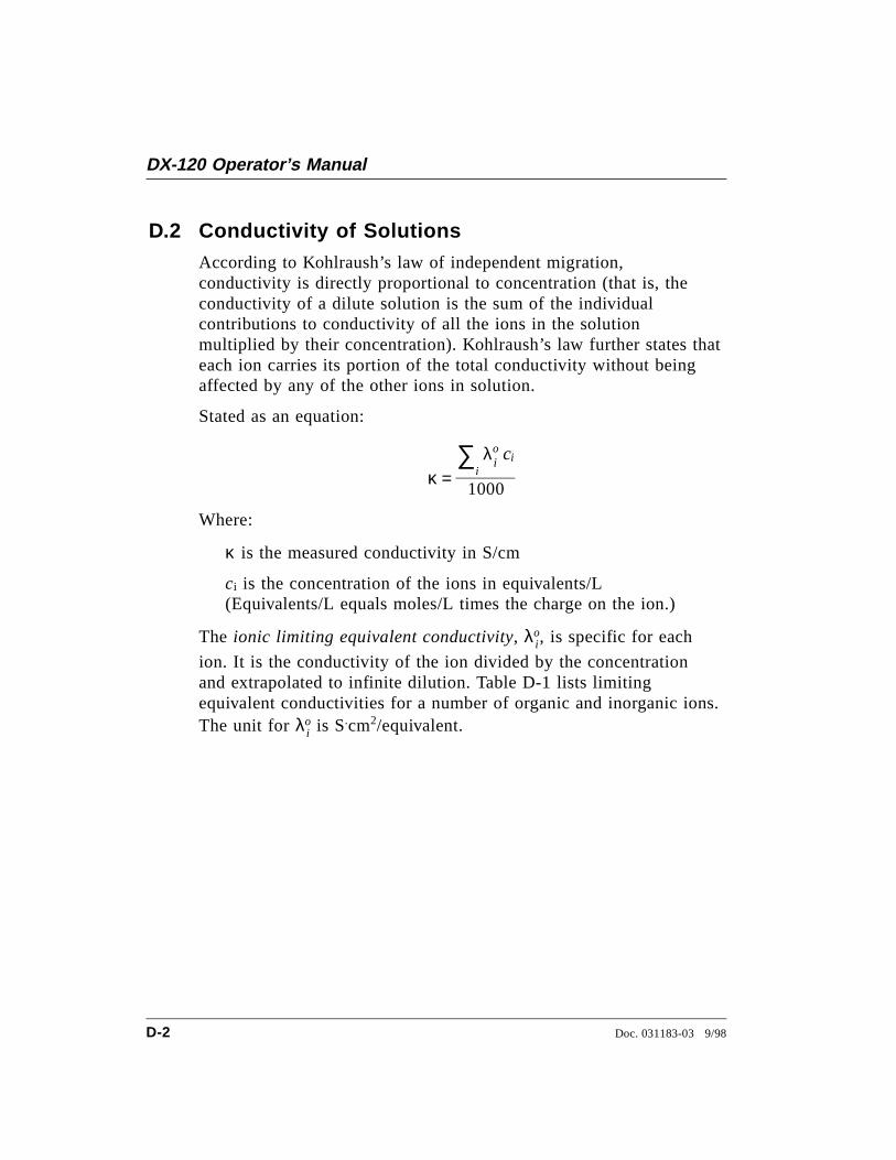
D.2 Conductivity of SolutionsAccording to Kohlraush’s law of independent migration,conductivity is directly proportional to concentration (that is, theconductivity of a dilute solution is the sum of the individualcontributions to conductivity of all the ions in the solutionmultiplied by their concentration). Kohlraush’s law further states thateach ion carries its portion of the total conductivity without beingaffected by any of the other ions in solution.
Stated as an equation:
κ = ∑
iλo
i ci
1000
Where:
κ is the measured conductivity in S/cm
ci is the concentration of the ions in equivalents/L(Equivalents/L equals moles/L times the charge on the ion.)
The ionic limiting equivalent conductivity, λoi , is specific for each
ion. It is the conductivity of the ion divided by the concentrationand extrapolated to infinite dilution. Table D-1 lists limitingequivalent conductivities for a number of organic and inorganic ions.The unit for λo
i is S.cm2/equivalent.
DX-120 Operator’s Manual
D-2 Doc. 031183-03 9/98
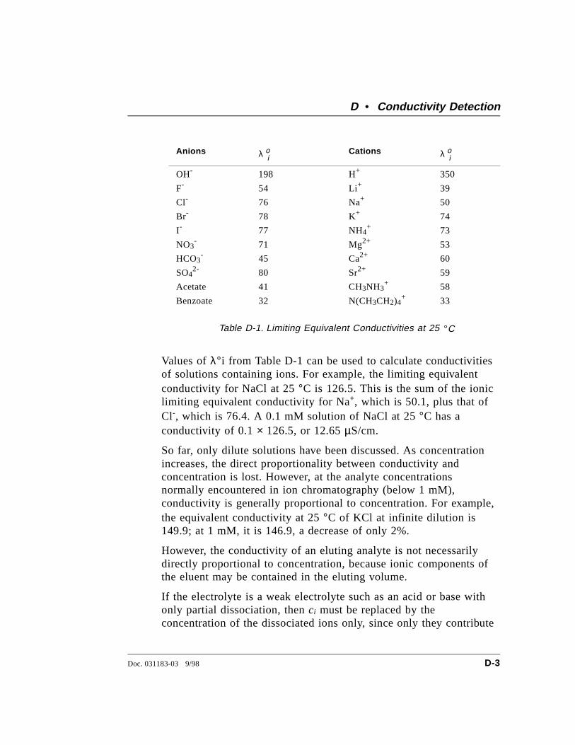
Values of λ°i from Table D-1 can be used to calculate conductivitiesof solutions containing ions. For example, the limiting equivalentconductivity for NaCl at 25 °C is 126.5. This is the sum of the ioniclimiting equivalent conductivity for Na+, which is 50.1, plus that ofCl-, which is 76.4. A 0.1 mM solution of NaCl at 25 °C has aconductivity of 0.1 × 126.5, or 12.65 µS/cm.
So far, only dilute solutions have been discussed. As concentrationincreases, the direct proportionality between conductivity andconcentration is lost. However, at the analyte concentrationsnormally encountered in ion chromatography (below 1 mM),conductivity is generally proportional to concentration. For example,the equivalent conductivity at 25 °C of KCl at infinite dilution is149.9; at 1 mM, it is 146.9, a decrease of only 2%.
However, the conductivity of an eluting analyte is not necessarilydirectly proportional to concentration, because ionic components ofthe eluent may be contained in the eluting volume.
If the electrolyte is a weak electrolyte such as an acid or base withonly partial dissociation, then ci must be replaced by theconcentration of the dissociated ions only, since only they contribute
Anions λ oiCations λ oi
OH- 198 H+ 350
F- 54 Li+ 39
Cl- 76 Na+ 50
Br- 78 K+ 74
I- 77 NH4+ 73
NO3- 71 Mg2+ 53
HCO3- 45 Ca2+ 60
SO42- 80 Sr2+ 59
Acetate 41 CH3NH3+ 58
Benzoate 32 N(CH3CH2)4+ 33
Table D-1. Limiting Equivalent Conductivities at 25 °C
D • Conductivity Detection
Doc. 031183-03 9/98 D-3
to conductivity. For acids and bases, the pK values and the solutionpH can be used to calculate the extent of dissociation.
D.2.1 Effect of Hydration Sphere and Solvent on Conductivity
The limiting equivalent conductivity of an ion, λoi , is a
measure of ionic mobility. Ionic mobility is greatly affectedby the properties of the ion in the solvent. Ions with largehydration spheres are less mobile, and therefore lessconductive, than ions with small hydration spheres. Thisexplains why λo
i for extensively hydrated fluoride (55.4) is
lower than λoi for chloride (76.4), which is less hydrated.
Solvent viscosity also affects ionic mobility; ions are moremobile in solvents of lower viscosity.
It is not necessary to know values such as hydration sphereand viscosity, since quantitative analysis is performed bycomparing the conductivity of the analyte in the sample tothe conductivity of the same analyte in a standard (orstandards). Even if a solvent gradient is used, thecomposition of the solvent during the elution of the analytewill be the same in both the sample and the standard.
D.2.2 Effect of Temperature on Conductivity
Ionic mobility, and therefore conductivity, is greatly affectedby temperature. The conductivity of an aqueous solution hasbeen found experimentally to rise a little less than 2% per °C.Thus, it is necessary to hold the eluent temperature asconstant as possible to maintain a stable baseline.
When the cell is housed in a DS4 Detection Stabilizer, theDS4 maintains the cell at a set temperature. In addition, thedetector corrects the measured conductivity to that whichwould be measured at 25 °C. It does this by measuring thecell temperature with a thermistor and multiplying theconductivity by a temperature-dependent constant. This
DX-120 Operator’s Manual
D-4 Doc. 031183-03 9/98
constant, the temperature compensation factor, is expressedin units of %/°C.
When operating with a standard cell (without a DS4), settingan accurate temperature compensation factor helps minimizethe baseline drift caused by fluctuations in ambienttemperature. See Section 3.6 for instructions on optimizingthe temperature compensation.
D.2.3 Species Detected by Conductivity
Conductivity detection is typically selected for species thatare ionic when they enter the detector cell, especially thosewith weak UV absorbance. This includes both organic andinorganic ions. Conductivity detection is best suited to anionsand cations of strong acids and bases, such as chloride,sulfate, trifluoroacetate, sodium, and potassium. Ions ofweaker acids are detected, provided that the eluent pH ischosen to maximize analyte dissociation. (When a suppressoris used, the eluent pH which determines whether an ion isdetected is the pH after suppression.)
Anions
Sensitivity is best for anions with pKa values below 6. Asanalyte ionization (dissociation) decreases, so does sensitivity.Anions with a pKa above 7 can be detected under certainconditions, but signal-to-noise ratios are generally poorer. Allorganic acids with either carboxylate, sulfonate, orphosphonate functional groups have pKa’s below 4.75, soconductivity is the preferred detection method for thesespecies. Common inorganic strong acid anions includechloride, nitrate, phosphate, and sulfate.
Cations
Inorganic cations detected include the alkali metals andalkaline earths. Most transition metal cations are not detected,since they either hydrolyze water to form anions or
D • Conductivity Detection
Doc. 031183-03 9/98 D-5

precipitate in the suppressor. These metals are usuallydetected by visible wavelength absorbance followingpostcolumn reaction with a chelating indicator.
Nearly all organic cations are amines. Aliphatic amines havepKa’s around 10 and are easily detected. Aromatic andheterocyclic amines have pKa’s between 2 and 7, too low tobe detected by suppressed conductivity following cationexchange separation. Although nonsuppressed(single-column) detection can be used for these species,sensitivity is generally poor. These amines are best detectedby UV absorbance or by amperometric techniques.
D.2.4 Chemical Suppression
Species detected by conductivity are by their nature ionic, soion-exchange and ion-pair chromatography are by far themost commonly used separation methods. These methodsrequire eluents containing strong electrolytes, which presentsa problem: how to detect the ionic analytes without thedetector being overwhelmed by the ions in the eluent. Thebest solution is to neutralize the eluent in a suppressor.
Figure D-1 illustrates the suppression mechanism that occursinside a Dionex Anion Self-Regenerating Suppressor (ASRS)when NaOH is the eluent for anion-exchange separation.
DX-120 Operator’s Manual
D-6 Doc. 031183-03 9/98
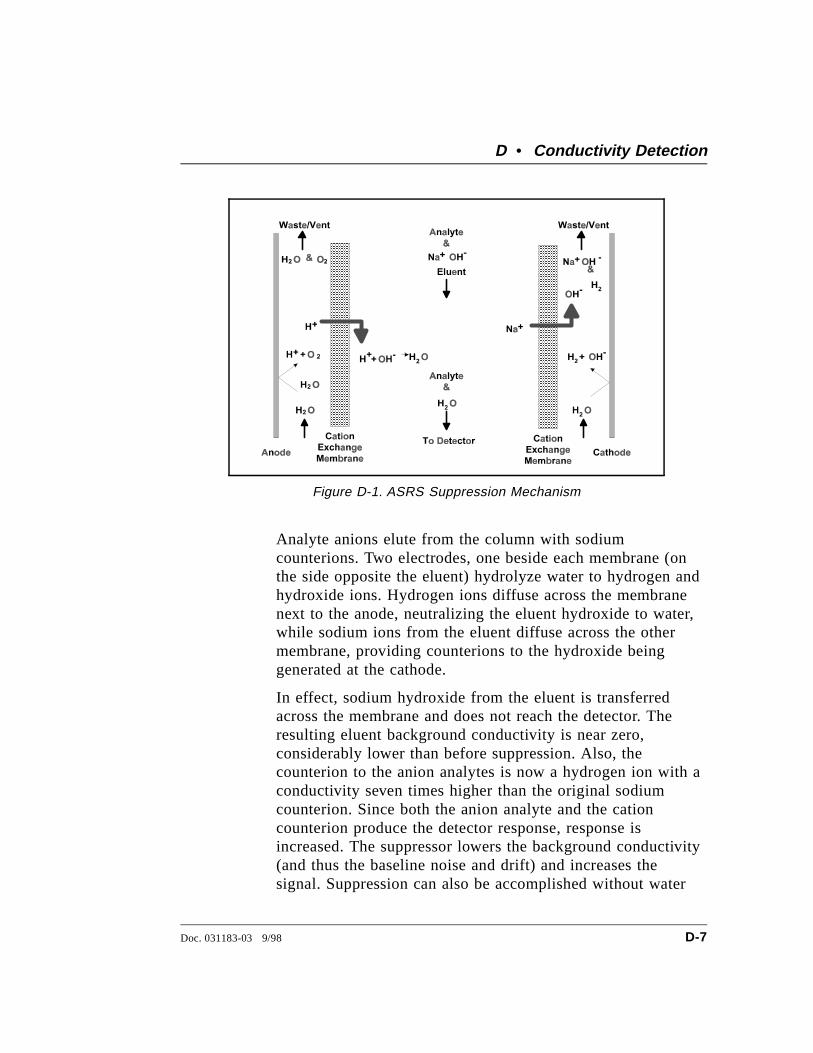
Analyte anions elute from the column with sodiumcounterions. Two electrodes, one beside each membrane (onthe side opposite the eluent) hydrolyze water to hydrogen andhydroxide ions. Hydrogen ions diffuse across the membranenext to the anode, neutralizing the eluent hydroxide to water,while sodium ions from the eluent diffuse across the othermembrane, providing counterions to the hydroxide beinggenerated at the cathode.
In effect, sodium hydroxide from the eluent is transferredacross the membrane and does not reach the detector. Theresulting eluent background conductivity is near zero,considerably lower than before suppression. Also, thecounterion to the anion analytes is now a hydrogen ion with aconductivity seven times higher than the original sodiumcounterion. Since both the anion analyte and the cationcounterion produce the detector response, response isincreased. The suppressor lowers the background conductivity(and thus the baseline noise and drift) and increases thesignal. Suppression can also be accomplished without water
Figure D-1. ASRS Suppression Mechanism
D • Conductivity Detection
Doc. 031183-03 9/98 D-7

electrolysis by pumping a dilute sulfuric acid solution (theregenerant) through the suppressor on the side of themembranes opposite the eluent.
For ion chromatography of cations, the suppressormembranes are anion exchange polymers that allow anions topass freely but exclude cations. The eluent uses dilute acidssuch as methanesulfonic acid. In the Dionex CationSelf-Regenerating Suppressor (CSRS), methanesulfonatecounterions are replaced by hydroxide generated by theelectrolysis of water. This neutralizes the acidic eluent andprovides the highly conductive hydroxide counterion to theanalyte cations.
Use of a suppressor typically increases signal-to-noise ratiosabout one order of magnitude for strong acid or base ions.The improvement is somewhat less for ions of weak acids orbases, due to decreased ionization at the neutral pH of theeluent after suppression. Nonetheless, the benefits fromreducing the background, and therefore the noise, almostalways yield a net improvement in signal-to-noise ratiocompared to nonsuppressed conductivity detection.
Suppressors provide several important advantages, listedbelow. The first three are a direct result of the increasedsignal-to-noise ratio.
• Lower detection limits
• Longer column life, due to a possible increase in thedilution of dirty samples
• Wider dynamic range
• Greater range of elution control and larger sampleconcentrations or volumes, due to more highlyconcentrated eluents
• Gradient elution capability
• Faster equilibration time
DX-120 Operator’s Manual
D-8 Doc. 031183-03 9/98
• Elimination of interference from counterions
• Elimination of system peaks
D.2.5 Eluents for Conductivity Detection
When choosing an eluent, the constraints imposed by theseparation and detection methods must be considered. Themost important criteria for obtaining optimal separation arethe elution strength of the eluent, the separation efficiency,and the resolution of the analytes of interest. For conductivitydetection, the criteria for a good eluent are the relativeconductivity response of the analytes and the magnitude ofthe background.
Eluents can be wholly aqueous, containing only water and astrong electrolyte. Or, if an organic solvent-compatiblecolumn such as a Dionex OmniPac® or MPIC® column isused, typical reversed-phase solvents such as methanol oracetonitrile can be used. Organic solvents are essentialcomponents of ion-pair eluents and provide importantselectivity control during ion-exchange separations. Sincethese solvents are nonconducting, they do not interfere withconductivity detection.
Anion-Exchange
When a suppressor is used, the ionic components of theeluent must be such that they are removed, or else convertedto weakly conducting compounds by the suppressor. Sodiumsalts of weak acids are used because they are converted to theneutral free-acid form in the suppressor. The higher the pKaof the acid, the lower the background conductivity followingsuppression. Weak acids with a pKa above 6 can be used forisocratic separations. For gradient elution, pKa’s should beabove 8 to minimize baseline shift during the gradient.
Sodium hydroxide solutions make excellent eluents foranion-exchange chromatography because hydroxide isneutralized in the suppressor to water (the free acid form of
D • Conductivity Detection
Doc. 031183-03 9/98 D-9
hydroxide). Another common eluent is a carbonate/bicarbonate buffer suppressed to carbonic acid (pKa = 6.2).Carbonate/bicarbonate buffers are easily prepared and areroutinely used for isocratic separations of inorganic anions.
Other eluents for suppressed anion chromatography includethe sodium salts of boric acid (borax, tetraborate, pKa = 9.2)and p-cyanophenol (pKa = 8.0). Borate forms weak bondswith hydroxy-organic acids, producing changes in selectivitycompared to hydroxide. p-Cyanophenol is a powerfulmonovalent displacer, useful for eluting strongly retainedhydrophobic monovalent anions such as fumaric acid, iodide,and thiocyanate.
Cation-Exchange
Millimolar concentrations of dilute strong acids, often mixedwith organic solvents, are good choices for cation exchangechromatography of both monovalent and divalent cations.Methanesulfonic acid (MSA) is commonly used, since it iscompatible with the CSRS.
Some columns require a stronger displacing ion thanhydrogen ion to elute more strongly retained divalent cations.The zwitterion 2,3-diaminopropionic acid (DAP), mixed witha strong acid to protonate the DAP, is a good choice.
The best eluents for nonsuppressed cation IC are dilute strongacids such as 1 mM nitric acid. Backgrounds are very high(around 1 µS), so signal-to-noise ratios are not good enoughfor low-level work. Since the conductivity of the hydrogenion is greater than that of all other cations, elution of analytescauses decreases in conductivity. Instead of peaks, elutinganalytes produce dips.
Ion-Pair
Eluents for ion-pair chromatography contain mixes ofaqueous and organic solvent solutions with hydrophobicion-pair reagents as additives. Commonly used reagents are
DX-120 Operator’s Manual
D-10 Doc. 031183-03 9/98
quaternary ammonium salts for anion separations andlong-chain sulfonates for cation separations. For suppressedconductivity detection, these reagents are easily usedprovided the counterions are either hydroxide (anion-ion pair)or hydrogen ion (cation-ion pair). These are marketed byDionex as IonSep® reagents. The reagents are purifiedsolutions of quaternary ammonium hydroxide solutions andsulfonic acid solutions.
D • Conductivity Detection
Doc. 031183-03 9/98 D-11

DX-120 Operator’s Manual
D-12 Doc. 031183-03 9/98
E • Glossary
Analytical ColumnSynonymous with Separator Column.
Band SpreadingThe broadening of the sample band as it travels through the column.Band spreading can also occur in the injection valve, detector cell,and interconnecting tubing.
Calibration CurveA graph showing detector response in peak height or area versusanalyte concentration.
Capacity Factor (k′)The number of column volumes of eluent, pumped through thecolumn, required to elute an analyte. Capacity factor is adimensionless measure of retention which is independent of columnlength or eluent flow rate. It is calculated as follows:
k′ = tr − to
to
Where: tr = retention time to = retention time of unretained solute (column void volume)
Cell Constant (k)A factor determined experimentally by measuring the conductance(G) of a standard solution of known equivalent conductivity (κ).
k = κ/G
The value of k depends upon the surface area of, and distancebetween, the electrode faces in the conductivity detector cell.
k = l /A
Where: l = length A = area of one electrode (the other electrode is equal to the first)
Doc. 031183-03 9/98 E-1

ChannelingThe preferential flow of liquid along more open, less resistant pathsthrough the column packing. This causes Band Spreading.
Column Efficiency (N)A measure of the narrowness of analyte bands as they elute from thecolumn. High efficiency is desirable because resolution betweenclosely spaced bands improves with greater efficiency. For asymmetrical (Gaussian) peak, column efficiency can be determinedby the following:
N = 5.54(t1/W1/2)2
Where: t1 = the peak retention time, in seconds W1/2 = the peak width at 1/2 height, in seconds
Column efficiency is proportional to column length: for a given resinand column diameter, increasing the column length increases thecolumn efficiency. Synonymous with Theoretical Plates.
Column Selectivity (α)Describes the relative separation of the band maxima between twoadjacent peaks. Selectivity can be determined by the following:
α = (t2 - t0)/(t1 -t0)
Where: t1 and t2 = retention time of components 1 and 2, respectively t0 = retention time of unretained components (void volume)
Concentrator ColumnA short column used to retain and concentrate analytes from ameasured volume of relatively clean sample. This allows largevolumes of sample to be injected, lowering concentration detectionlimits.
ConductivityA measure of the ease with which electrical current flows through aliquid contained between two opposite charged electrodes.Conductivity is a characteristic of ions in solution. Units are siemens.
DX-120 Operator’s Manual
E-2 Doc. 031183-03 9/98
CounterionIons carrying a charge opposite that of the sample ions (e.g., Na+)may be the counterion of a Cl- analyte. These ions preserve electricalneutrality in solution.
% CrosslinkDivinylbenzene content in a polystyrene/divinylbenzene (PS-DVB)resin; this contributes to the mechanical strength of the resin anddetermines chromatographic properties.
Equivalent Conductivity (λ)The contribution of an ionic species to the total conductivity of asolution as measured in a standard cell having electrodes 1 cm2 inarea and exactly 1 cm apart.
Guard ColumnA small column which prevents poisoning of the separator columnby sorbing organic contaminants and removing particulates. It isfilled with the same packing as the separator column. Synonymouswith Pre-Column.
HETP (H)Height Equivalent to a Theoretical Plate. A measure of columnefficiency which allows comparison between columns of differentlengths.
HETP = H = L/N
Where: L = the column length (mm) N = the number of theoretical plates
Ion-Exchange CapacityThe number of active ion exchange sites in a given weight orvolume of resin, most often expressed in meq/g or meq/mL.
Ion-Exchange ResinAn insoluble polymer matrix containing fixed-charge exchange sites(anionic or cationic). IC resins are formed into small sphericalparticles (beads).
E • Glossary
Doc. 031183-03 9/98 E-3
PackingThe material which fills a chromatographic column; usually aresin or silica-based material.
Pellicular ResinA resin with a solid, nonporous core coated with a thin layer ofmore porous material. The exchange sites of pellicular ion exchangeresins are located only on the surface layer of the bead. These resinshave a low ion-exchange capacity.
Pre-ColumnSynonymous with Guard Column.
RegenerantA dilute acid or base which converts ion exchange sites in thesuppressor back to the form which will suppress the eluentconductivity.
ResinSee Ion-Exchange Resin.
Resolution (R)A measure of the separation between two sample components. It isexpressed as the ratio of the distance between the two peak maximato the mean value of the peak width at the baseline.
R = 2(t2 - t1)/(W2 + W1)
Where: t1 and t2 =the retention times of components 1 and 2, respectivelyW1 and W1 = the baseline width of peaks 1 and 2,respectively (measured in the same units as the retentiontime)
R is proportional to the square root of efficiency (N). A value of R =1.5 represents “baseline separation” of the two peaks.
Retention TimeThe time from injection to peak maximum; the basis foridentification of a species in chromatographic analysis.
DX-120 Operator’s Manual
E-4 Doc. 031183-03 9/98
Separator ColumnThe column used to perform a chromatographic separations; alsocalled analytical column.
Siemens (S)Unit measure of conductance; the reciprocal of the electricalresistance of a solution.
SuppressorA device used to minimize eluent conductivity and convert samplespecies to a common form, thus increasing detection sensitivity.
Temperature CoefficientThe percent of change in the conductivity of a solution with a 1 oCchange in temperature. Every solution has a characteristictemperature coefficient which is determined experimentally.
Theoretical Plates (N)See Column Efficiency.
Void Volume (V0)The volume occupied by the eluent in a packed column. This volumeincludes the volume between the injection valve and the column, aswell as between the column and the detector cell. Unretainedcomponents are eluted in the void volume.
E • Glossary
Doc. 031183-03 9/98 E-5

DX-120 Operator’s Manual
E-6 Doc. 031183-03 9/98
Index
AAbnormal retention time, 4-11Abnormal selectivity, 4-11Air particulates, 3-3Alarm Reset button, 2-4Alarms, 4-1
Clearing, 2-4Enabling/disabling the low pressure, B-31Enabling/disabling the sound, B-31Setting the high pressure alarm limit, B-31Troubleshooting, 4-1
Amines, D-6Analog output, 2-4
At injection, 3-8Filtering, B-32Offsetting, B-32Specifications, A-1
Analytical columns, 2-8Anion exchange, D-9Anions
Detection of, D-5Area percent mode, C-2AS3500 Automated Sampler
TTL connections, B-24AS40 Automated Sampler
Controlling with an integrator, C-3TTL connections, B-22
Auto Inject Reset DIP switch, B-31Auto offset
At injection, 3-8At start-up, 3-6Enabling/disabling at injection, B-31
Auto Offset button, 2-5, 3-6Automation cable, B-27, C-1Autosampler, 3-7
AS3500 connections, B-24AS40 connections, B-22Installation, B-22
AutoSuppression recycle mode schematic, B-11Auxiliary power outlet connection, B-4
BBackground conductivity
Offsetting, 2-5, 3-6Offsetting at injection, 3-8
BackpressureCoils required, B-12Requirements, B-12Troubleshooting, 4-9, 5-3
BaselineDrifting and/or noisy, 4-15Oscillations, 2-13Zeroing, 2-5
BASIC programming, C-7Bottles, 2-7Buttons
Alarm Reset, 2-4Auto Offset, 2-5Column A, 2-5Column B, 2-5Eluent Pressure, 2-4Flow Setting, 2-3Full Scale, 2-4Load/Inject, 2-5Local/Remote, 2-4Mark, 2-4Offset Cond, 2-3Pressure, 2-3Pump, 2-4SRS, 2-4Total Cond, 2-3Zero, 2-4
CCalibrating
Cell constant, 5-6Pump flow rate, B-9
CalibrationIntegrator method, C-4
Cation exchange, D-10Cations
Detection of, D-5
Doc. 031183-03 9/98 Index-1
CDM-3 cell, 2-8, 2-12, 3-10, B-32Installation, B-35
Cell constant, 2-12Cell leak alarm, 4-1CELL TEMP display, 3-6CELL TEMP HI, 3-6, 4-12Cell Type DIP switches, B-32Cell volume, 2-12Cells, 2-8
Calibrating the cell constant, 5-6Cleaning, 5-5Description, 2-12Optimizing temperature compensation, 3-10Specifications, A-3Testing the electronics, B-32
Chart mark, 2-4, B-32At injection, 3-8
Check valves, 5-8Chemical suppression, D-6Chromatogram
Troubleshooting, 4-10Zeroing the baseline, 2-5
Chromatography components, 2-8Installation, B-10
Cleaning cell electrodes, 5-4Cleaning pump check valves, 5-8Clearing an alarm, 2-4Clips for column mounting, B-17Column A button, 2-5Column B button, 2-5Column Configuration DIP switches, B-31Column mounting clip, B-17Column select mode, 2-16
Enabling, B-31Schematic, 2-20
COLUMN SELECTION buttons, 2-5Column switching sequence, 2-16Column switching valve, 2-8, 2-15Columns, 2-8
Installation, B-17COMPONENT ON/OFF buttons, 2-4Component panel, 2-8
Dual-column layout, 2-10Single-column layout, 2-9
ConductivityAffected by temperature, 2-13, D-4Displaying, 2-3
Effect of hydration sphere and solvent on, D-4Measurement, D-1Of solutions, D-2Offsetting the background, 2-5, 3-6, 3-8Suppressing eluent, 2-13, D-6
Conductivity detectionEluents for, D-9
ConfigurationColumn select mode flow schematic, 2-20Dual-column features, 2-15Eluent select mode flow schematic, 2-21Single-column flow schematic, 2-19
Configuration DIP switches, B-29Control modes, 2-22Control panel, 2-3Conventions, manual, 1-3Counterions, D-7
DDegassing eluents, 2-7, 3-1Delay volume, A-4Detector
Specifications, A-2Troubleshooting, 4-13
Dialog, C-3Diluting samples, 3-4DIP switches, B-29
Alarm Sound, B-31Auto Inject Reset, B-31Auto Offset, B-31Cell Type, 2-12, B-32Column Configuration, B-31Column Select Mode, 2-15, B-31DS4 Temperature, B-31Filter Enable, B-32Full Scale Voltage, B-32High Pressure Alarm, B-31Inject Mark, B-32Low Pressure Alarm, B-31Offset, B-32Polarity, B-32Pressure Units, B-31Pump Time-out, 2-6, B-31Range, B-32Response Time, B-32Signal Temperature Compensation, B-32
DX-120 Operator’s Manual
Index-2 Doc. 031183-03 9/98
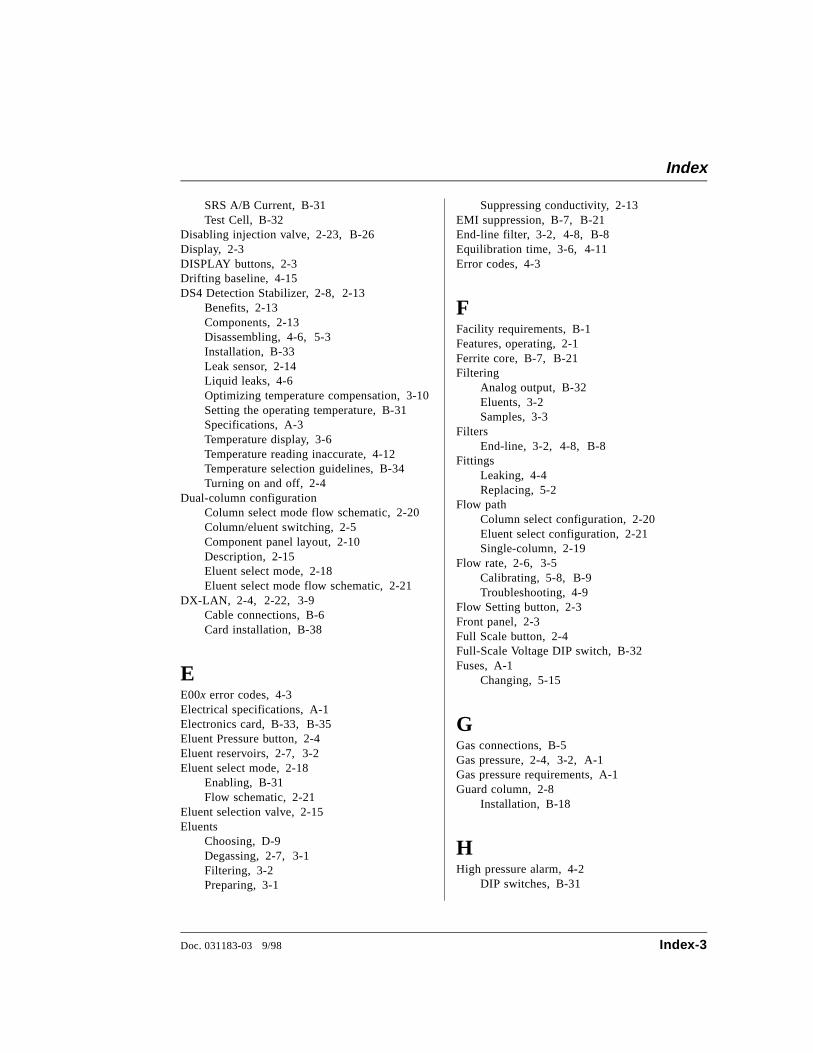
SRS A/B Current, B-31Test Cell, B-32
Disabling injection valve, 2-23, B-26Display, 2-3DISPLAY buttons, 2-3Drifting baseline, 4-15DS4 Detection Stabilizer, 2-8, 2-13
Benefits, 2-13Components, 2-13Disassembling, 4-6, 5-3Installation, B-33Leak sensor, 2-14Liquid leaks, 4-6Optimizing temperature compensation, 3-10Setting the operating temperature, B-31Specifications, A-3Temperature display, 3-6Temperature reading inaccurate, 4-12Temperature selection guidelines, B-34Turning on and off, 2-4
Dual-column configurationColumn select mode flow schematic, 2-20Column/eluent switching, 2-5Component panel layout, 2-10Description, 2-15Eluent select mode, 2-18Eluent select mode flow schematic, 2-21
DX-LAN, 2-4, 2-22, 3-9Cable connections, B-6Card installation, B-38
EE00x error codes, 4-3Electrical specifications, A-1Electronics card, B-33, B-35Eluent Pressure button, 2-4Eluent reservoirs, 2-7, 3-2Eluent select mode, 2-18
Enabling, B-31Flow schematic, 2-21
Eluent selection valve, 2-15Eluents
Choosing, D-9Degassing, 2-7, 3-1Filtering, 3-2Preparing, 3-1
Suppressing conductivity, 2-13EMI suppression, B-7, B-21End-line filter, 3-2, 4-8, B-8Equilibration time, 3-6, 4-11Error codes, 4-3
FFacility requirements, B-1Features, operating, 2-1Ferrite core, B-7, B-21Filtering
Analog output, B-32Eluents, 3-2Samples, 3-3
FiltersEnd-line, 3-2, 4-8, B-8
FittingsLeaking, 4-4Replacing, 5-2
Flow pathColumn select configuration, 2-20Eluent select configuration, 2-21Single-column, 2-19
Flow rate, 2-6, 3-5Calibrating, 5-8, B-9Troubleshooting, 4-9
Flow Setting button, 2-3Front panel, 2-3Full Scale button, 2-4Full-Scale Voltage DIP switch, B-32Fuses, A-1
Changing, 5-15
GGas connections, B-5Gas pressure, 2-4, 3-2, A-1Gas pressure requirements, A-1Guard column, 2-8
Installation, B-18
HHigh pressure alarm, 4-2
DIP switches, B-31
Index
Doc. 031183-03 9/98 Index-3
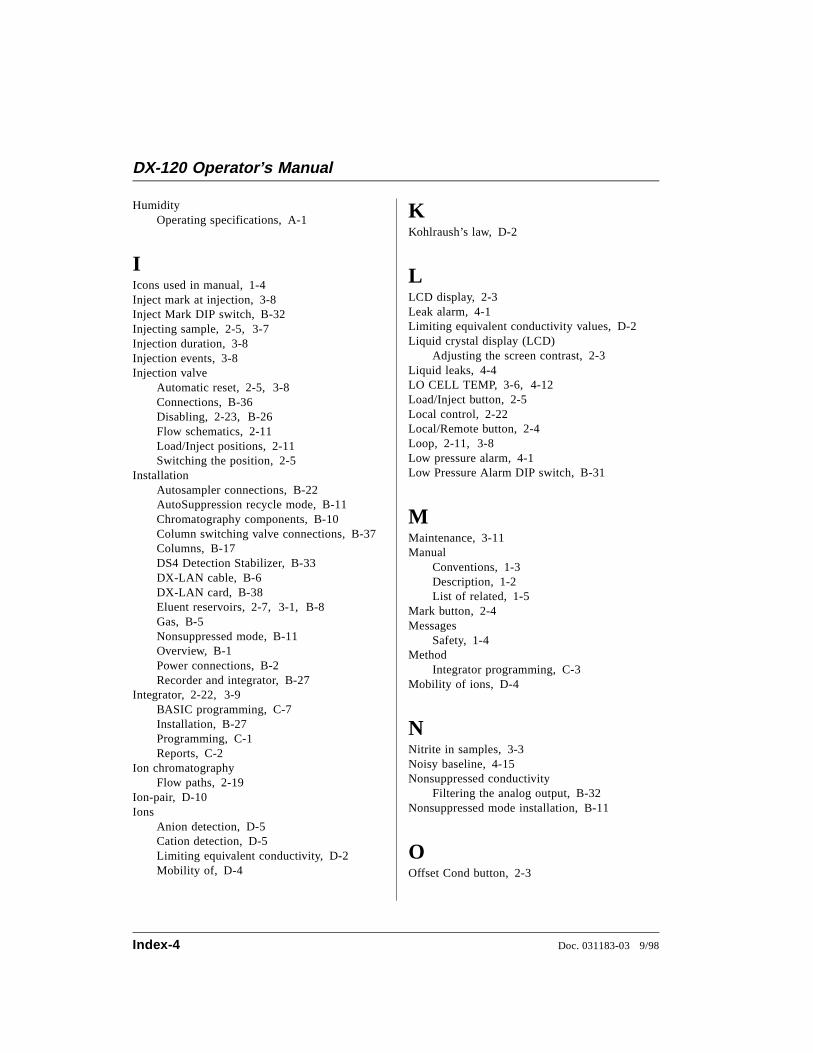
HumidityOperating specifications, A-1
IIcons used in manual, 1-4Inject mark at injection, 3-8Inject Mark DIP switch, B-32Injecting sample, 2-5, 3-7Injection duration, 3-8Injection events, 3-8Injection valve
Automatic reset, 2-5, 3-8Connections, B-36Disabling, 2-23, B-26Flow schematics, 2-11Load/Inject positions, 2-11Switching the position, 2-5
InstallationAutosampler connections, B-22AutoSuppression recycle mode, B-11Chromatography components, B-10Column switching valve connections, B-37Columns, B-17DS4 Detection Stabilizer, B-33DX-LAN cable, B-6DX-LAN card, B-38Eluent reservoirs, 2-7, 3-1, B-8Gas, B-5Nonsuppressed mode, B-11Overview, B-1Power connections, B-2Recorder and integrator, B-27
Integrator, 2-22, 3-9BASIC programming, C-7Installation, B-27Programming, C-1Reports, C-2
Ion chromatographyFlow paths, 2-19
Ion-pair, D-10Ions
Anion detection, D-5Cation detection, D-5Limiting equivalent conductivity, D-2Mobility of, D-4
KKohlraush’s law, D-2
LLCD display, 2-3Leak alarm, 4-1Limiting equivalent conductivity values, D-2Liquid crystal display (LCD)
Adjusting the screen contrast, 2-3Liquid leaks, 4-4LO CELL TEMP, 3-6, 4-12Load/Inject button, 2-5Local control, 2-22Local/Remote button, 2-4Loop, 2-11, 3-8Low pressure alarm, 4-1Low Pressure Alarm DIP switch, B-31
MMaintenance, 3-11Manual
Conventions, 1-3Description, 1-2List of related, 1-5
Mark button, 2-4Messages
Safety, 1-4Method
Integrator programming, C-3Mobility of ions, D-4
NNitrite in samples, 3-3Noisy baseline, 4-15Nonsuppressed conductivity
Filtering the analog output, B-32Nonsuppressed mode installation, B-11
OOffset Cond button, 2-3
DX-120 Operator’s Manual
Index-4 Doc. 031183-03 9/98
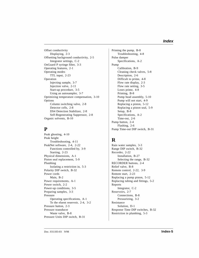
Offset conductivityDisplaying, 2-3
Offsetting background conductivity, 2-5Integrator settings, C-2
OnGuard P syringe filter, 3-3Operating features, 2-1Operating modes
TTL input, 2-23Operation
Injecting sample, 3-7Injection valve, 2-11Start-up procedure, 3-5Using an autosampler, 3-7
Optimizing temperature compensation, 3-10Options
Column switching valve, 2-8Detector cells, 2-8DS4 Detection Stabilizer, 2-8Self-Regenerating Suppressor, 2-8
Organic solvents, B-10
PPeak ghosting, 4-10Peak height
Troubleshooting, 4-11PeakNet software, 2-4, 2-22
Functions controlled by, 3-9Starting, 2-23
Physical dimensions, A-1Piston seal replacement, 5-9Plumbing
Isolating a restriction in, 5-3Polarity DIP switch, B-32Power cords
Main, B-2Power requirements, A-1Power switch, 2-2Power-up conditions, 3-5Preparing samples, 3-3Pressure
Operating specifications, A-1To the eluent reservoir, 2-4, 3-2
Pressure button, 2-3Pressure transducer
Waste valve, B-8Pressure Units DIP switch, B-31
Priming the pump, B-8Troubleshooting, 4-8
Pulse damperSpecifications, A-2
PumpCalibration, B-9Cleaning check valves, 5-8Description, 2-6Difficult to prime, 4-8Flow rate display, 2-3Flow rate setting, 3-5Loses prime, 4-8Priming, B-8Pump head assembly, 5-10Pump will not start, 4-9Replacing a piston, 5-12Replacing a piston seal, 5-9Setup, B-8Specifications, A-2Time-out, 2-6
Pump button, 2-4Flashing, 2-6
Pump Time-out DIP switch, B-31
RRain water samples, 3-3Range DIP switch, B-32Recorder, 2-22
Installation, B-27Selecting the range, B-32
RECORDER buttons, 2-4Relief valve, B-8Remote control, 2-22, 3-9Remote start, 2-23Replacing a pump piston, 5-12Replacing tubing and fittings, 5-2Reports
Integrator, C-2Reservoirs, 2-7
Connections, B-8Pressurizing, 3-2
ResistanceSolution, D-1
Response Time DIP switches, B-32Restriction in plumbing, 5-3
Index
Doc. 031183-03 9/98 Index-5
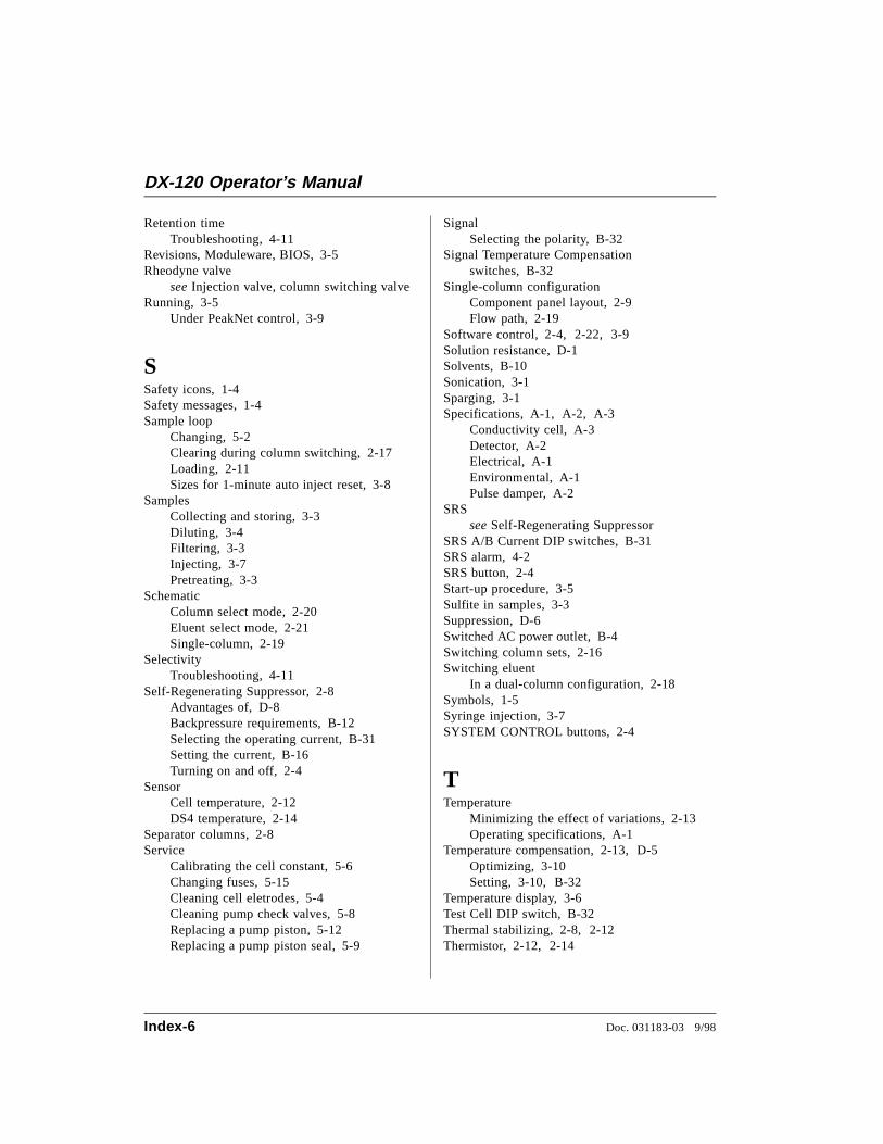
Retention timeTroubleshooting, 4-11
Revisions, Moduleware, BIOS, 3-5Rheodyne valve
see Injection valve, column switching valveRunning, 3-5
Under PeakNet control, 3-9
SSafety icons, 1-4Safety messages, 1-4Sample loop
Changing, 5-2Clearing during column switching, 2-17Loading, 2-11Sizes for 1-minute auto inject reset, 3-8
SamplesCollecting and storing, 3-3Diluting, 3-4Filtering, 3-3Injecting, 3-7Pretreating, 3-3
SchematicColumn select mode, 2-20Eluent select mode, 2-21Single-column, 2-19
SelectivityTroubleshooting, 4-11
Self-Regenerating Suppressor, 2-8Advantages of, D-8Backpressure requirements, B-12Selecting the operating current, B-31Setting the current, B-16Turning on and off, 2-4
SensorCell temperature, 2-12DS4 temperature, 2-14
Separator columns, 2-8Service
Calibrating the cell constant, 5-6Changing fuses, 5-15Cleaning cell eletrodes, 5-4Cleaning pump check valves, 5-8Replacing a pump piston, 5-12Replacing a pump piston seal, 5-9
SignalSelecting the polarity, B-32
Signal Temperature Compensation switches, B-32
Single-column configurationComponent panel layout, 2-9Flow path, 2-19
Software control, 2-4, 2-22, 3-9Solution resistance, D-1Solvents, B-10Sonication, 3-1Sparging, 3-1Specifications, A-1, A-2, A-3
Conductivity cell, A-3Detector, A-2Electrical, A-1Environmental, A-1Pulse damper, A-2
SRSsee Self-Regenerating Suppressor
SRS A/B Current DIP switches, B-31SRS alarm, 4-2SRS button, 2-4Start-up procedure, 3-5Sulfite in samples, 3-3Suppression, D-6Switched AC power outlet, B-4Switching column sets, 2-16Switching eluent
In a dual-column configuration, 2-18Symbols, 1-5Syringe injection, 3-7SYSTEM CONTROL buttons, 2-4
TTemperature
Minimizing the effect of variations, 2-13Operating specifications, A-1
Temperature compensation, 2-13, D-5Optimizing, 3-10Setting, 3-10, B-32
Temperature display, 3-6Test Cell DIP switch, B-32Thermal stabilizing, 2-8, 2-12Thermistor, 2-12, 2-14
DX-120 Operator’s Manual
Index-6 Doc. 031183-03 9/98
Time functions, B-27Integrator programming, C-3
Timed eventsIntegrator method, C-4
Total Cond button, 2-3Total conductivity
Displaying, 2-3Transition metal cations, D-5Troubleshooting
Abnormal retention time, 4-11Abnormal selectivity, 4-11Detector output, 4-13DS4 leaks, 4-6DS4 temperature reading inaccurate, 4-12Excessive backpressure, 4-9Flow rate, 4-9Liquid leaks, 4-4Peak ghosting, 4-10Peak height, 4-11Pump difficult to prime, 4-8Retention time, 4-11Selectivity, 4-11
TTL inputsAS40 Automated Sampler connections, B-22,B-24Integrator connections, B-28
TTL outputsAS3500 Automated Sampler connections, B-24AS40 Automated Sampler connections, B-22At injection, 3-8Integrator connections, B-28
TTL/Relay control, 2-23
TubingReplacing, 5-2
VValve
Column switching, 2-8, 2-15Column switching connections, B-37Eluent selection, 2-15Injection valve auto reset, 2-5Injection valve connections, B-36Injection valve description, 2-11Injection valve switching, 2-5Specifications, A-3
VoltageFull-scale output, B-32
WWaste lines, B-5
Blocked, 4-4Waste valve, B-8Water samples, 3-3Wire connections, B-27
ZZero button, 2-4Zeroing the analog output signal, 2-4Zeroing the baseline, 2-5
At injection, 3-8
Index
Doc. 031183-03 9/98 Index-7

DX-120 Operator’s Manual
Index-8 Doc. 031183-03 9/98