Embed Size (px)
Citation preview

Thank you for purchasing our product. Please read this user’s manual before using the product. Change without notice
16CH Hybrid DVR_ User Manual (AHD+TVI+IP+960H)
2
CAUTION
Please read this user manual carefully to ensure that you can use the device correctly and safely
We do not warrant all the content is correct. The contents of this manual are subject to change without notice
This device should be operated only from the type of power source indicated on the marking label. The voltage of the power must be verified before using. If not in use for a long time, pull out the plug from the socket
Do not install this device near any heat sources such as radiators, heat registers, stoves or other device that produce heat
Do not install this device near water. Clean only with a dry cloth
Do not block any ventilation openings. And ensure well ventilation around the machine
Do not power off the DVR at normal recording condition! The correct operation to shut off DVR is to stop recording firstly, and then select “shut-down” button at the right of the menu bar to exit, and finally to cut off the power.
This machine is indoor using equipment. Do not expose the machine in rain or moist environment. In case any solid or liquid get into the machine’s case, please cut off the power supply immediately, and ask for qualified technicians to check the machine before restart
Refer all servicing to qualified service personnel. No any parts repaired by yourself without technical aid or approval.
3
Main Features
Real-time surveillance High resolution VGA output, HDMI output 2 way audio 3G Mobile surveillance(iPhone/ iPad/ Android)
Compression with latest H.264 video compression, better video quality and lower compression rate.
Storage: 8 SATA HDD(FAT32 file system)
Data back with USB thumb drive or USB external DVD burner. Each backup file size is 128MB.
Adjustable record resolution, frame rate and quality WD1(960H)/AHD 720P+1080P/TVI720P+1080P/IP 720P+1080P
(support 8 IP camera input) record Multi-record mode: manual, schedule, sensor and motion record. HDD recycle record. Single or Multi channel playback Record file lock protection With 16 channel Audio input / 1 channel audio output
With 16 channel alarm inputs / 4 channel alarm output Motion detection Pre and Post event record Channel related trigger record PTZ control
Multi PTZ protocol support Programmable 128 Preset points and 8 cruises Related trigger preset point control
Authority account setup (1 admin and 63 users account) USB mouse control
To use USB mouse to control on friendly GUI Playback search mode: by time or event Event log and search Support network function
Multi connection type: STATIC (Fixed IP), DHCP, PPPOE
Support DDNS、NAT (P2P)
Support event trigger to send E-mail Remote connection limitation Auto bandwidth adjustment by network status
Support network remote control Remote record Remote playback Remote PTZ control Remote configuration Remote IE surveillance Remote CMS control Remote EMAP control Remote camera color adjustment Remote snapshot Supports COC ( control over coaxial) function
4
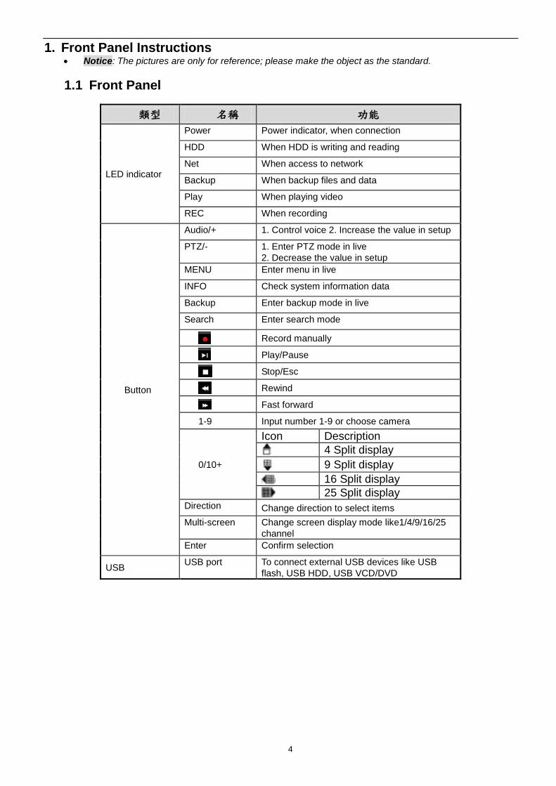
1. Front Panel Instructions Notice: The pictures are only for reference; please make the object as the standard.
1.1 Front Panel
類型 名稱 功能
LED indicator
Power Power indicator, when connection
HDD When HDD is writing and reading
Net When access to network
Backup When backup files and data
Play When playing video
REC When recording
Button
Audio/+ 1. Control voice 2. Increase the value in setup
PTZ/- 1. Enter PTZ mode in live
2. Decrease the value in setup
MENU Enter menu in live
INFO Check system information data
Backup Enter backup mode in live
Search Enter search mode
Record manually
Play/Pause
Stop/Esc
Rewind
Fast forward
1-9 Input number 1-9 or choose camera
0/10+
Icon Description
4 Split display
9 Split display
16 Split display
25 Split display Direction Change direction to select items
Multi-screen Change screen display mode like1/4/9/16/25
channel
Enter Confirm selection
USB USB port To connect external USB devices like USB
flash, USB HDD, USB VCD/DVD

5
1.2 Rear Panel Instructions
Rear Panel for 16 CH
Name Descriptions AC110/230 Power Input.
USB To connect external USB devices like USB mouse or USB storage device.
LAN Network Port.
HDMI HDMI Port. Connect to high-definition display device.
VGA VGA Port. Connect to monitor.
E-SATA External HDD for backup
VIDEO IN 16 CH Video Inputs.(support AHD/TVI/Analogue)
AUDIO OUT Audio output, connect to the sound box.
AUDIO IN 16 CH Audio Input.
RS485 Connect to keyboard or speed dome; A is TX +; B is TX-.
ALARM IN 16 channel alarm inputs
ALARM OUT 4 channel alarm output
6
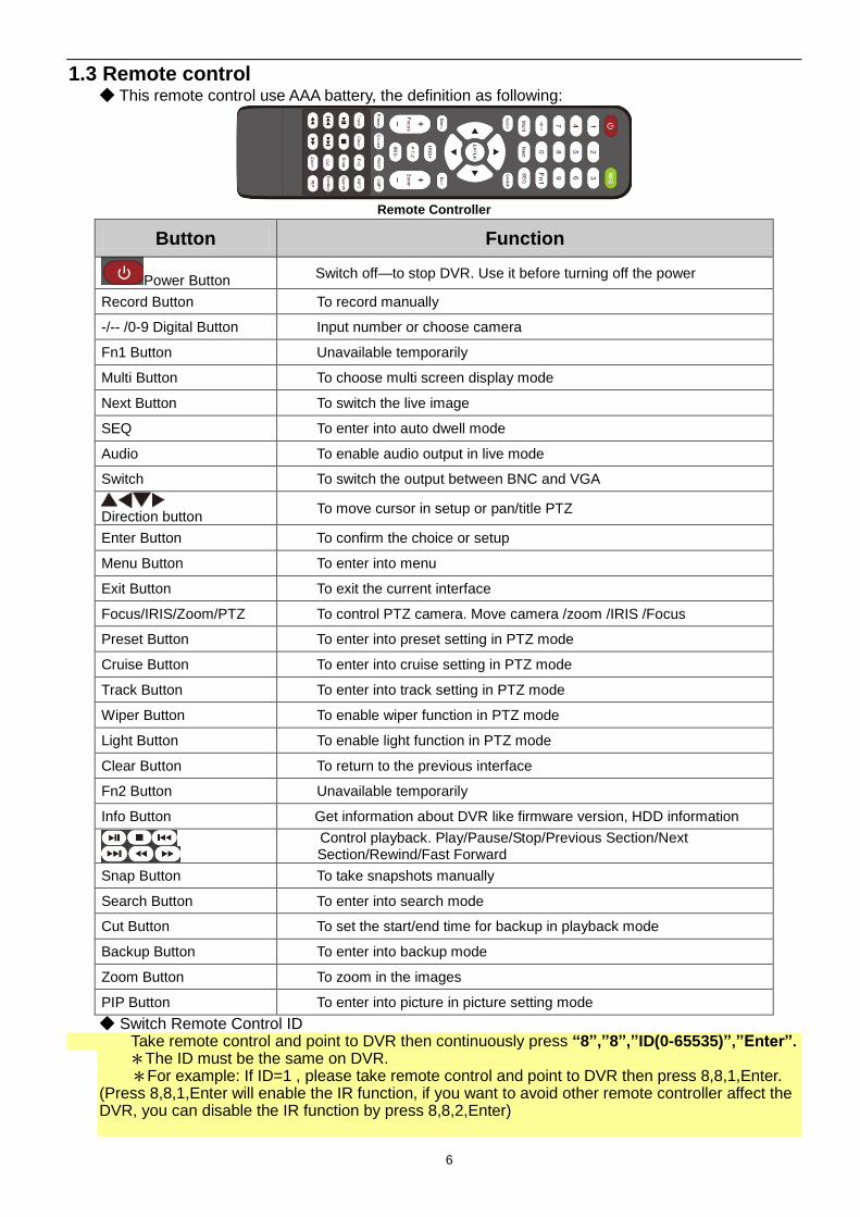
1.3 Remote control ◆ This remote control use AAA battery, the definition as following:
Remote Controller
Button Function
Power Button Switch off—to stop DVR. Use it before turning off the power
Record Button To record manually
-/-- /0-9 Digital Button Input number or choose camera
Fn1 Button Unavailable temporarily
Multi Button To choose multi screen display mode
Next Button To switch the live image
SEQ To enter into auto dwell mode
Audio To enable audio output in live mode
Switch To switch the output between BNC and VGA
Direction button
To move cursor in setup or pan/title PTZ
Enter Button To confirm the choice or setup
Menu Button To enter into menu
Exit Button To exit the current interface
Focus/IRIS/Zoom/PTZ To control PTZ camera. Move camera /zoom /IRIS /Focus
Preset Button To enter into preset setting in PTZ mode
Cruise Button To enter into cruise setting in PTZ mode
Track Button To enter into track setting in PTZ mode
Wiper Button To enable wiper function in PTZ mode
Light Button To enable light function in PTZ mode
Clear Button To return to the previous interface
Fn2 Button Unavailable temporarily
Info Button Get information about DVR like firmware version, HDD information
To Control playback. Play/Pause/Stop/Previous Section/Next Section/Rewind/Fast Forward
Snap Button To take snapshots manually
Search Button To enter into search mode
Cut Button To set the start/end time for backup in playback mode
Backup Button To enter into backup mode
Zoom Button To zoom in the images
PIP Button To enter into picture in picture setting mode
◆ Switch Remote Control ID Take remote control and point to DVR then continuously press “8”,”8”,”ID(0-65535)”,”Enter”.
*The ID must be the same on DVR. *For example: If ID=1 , please take remote control and point to DVR then press 8,8,1,Enter. (Press 8,8,1,Enter will enable the IR function, if you want to avoid other remote controller affect the DVR, you can disable the IR function by press 8,8,2,Enter)
7
1.4 Mouse Control ◆Connection: Please connect the USB mouse to USB port on the front or back panel. ◆Mouse functions: 1)Under LIVE mode:
On every channel,you could double click the left button to switch FULL SCREEN and double click again to switch back to original split mode.
On every channel,you could single click right button to popup MENU page. 2)Under MENU page:
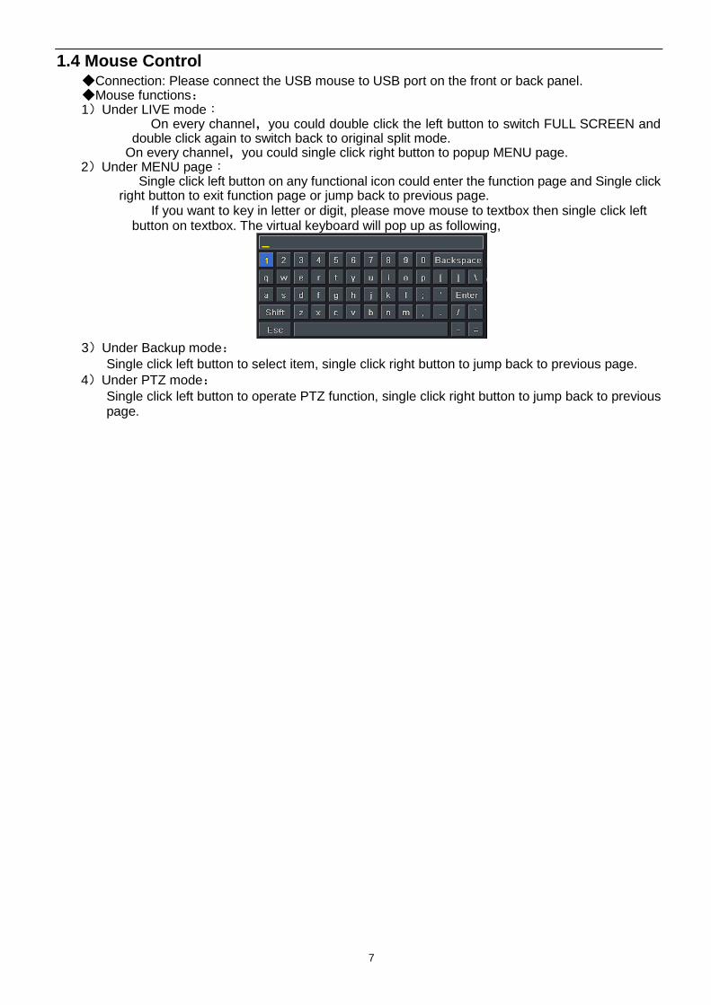
Single click left button on any functional icon could enter the function page and Single click right button to exit function page or jump back to previous page.
If you want to key in letter or digit, please move mouse to textbox then single click left button on textbox. The virtual keyboard will pop up as following,
3)Under Backup mode:
Single click left button to select item, single click right button to jump back to previous page.
4)Under PTZ mode:
Single click left button to operate PTZ function, single click right button to jump back to previous page.
8
2 Basic Function Instruction
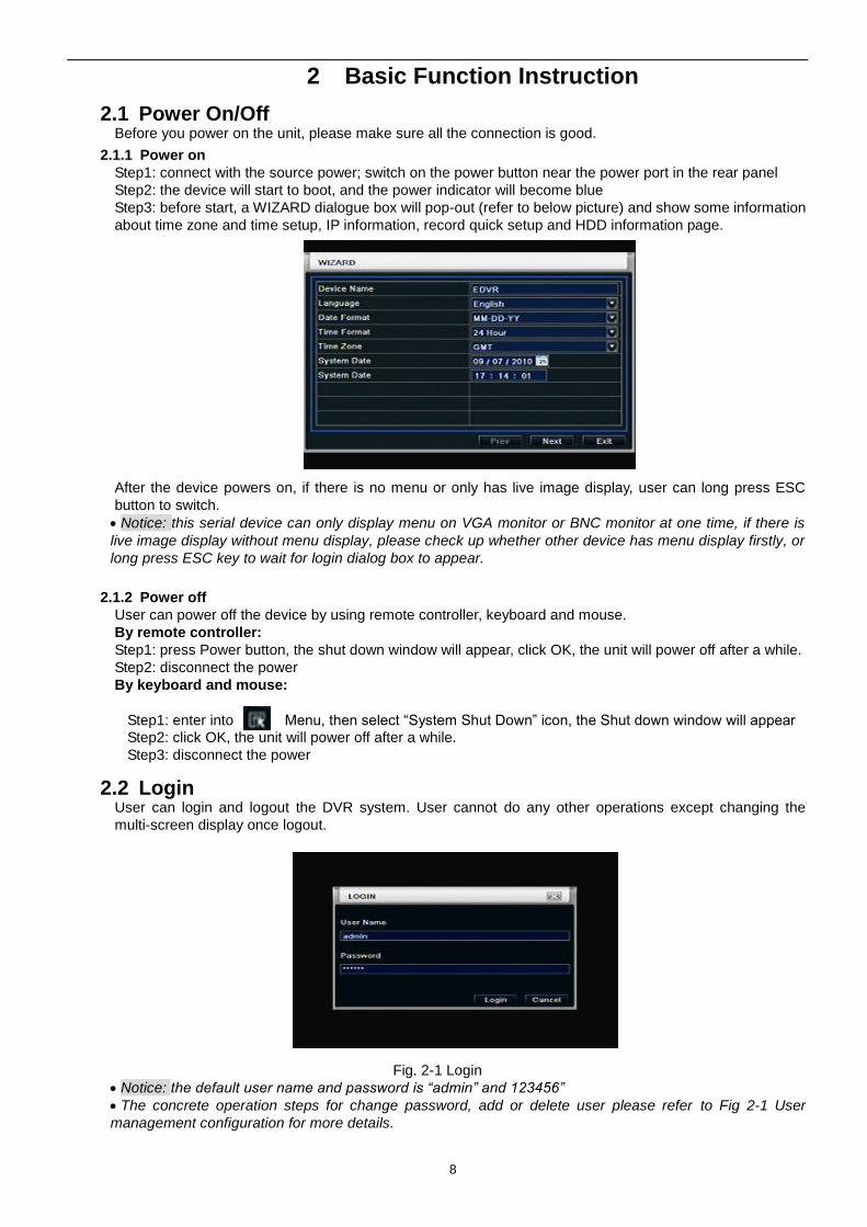
2.1 Power On/Off Before you power on the unit, please make sure all the connection is good.
2.1.1 Power on
Step1: connect with the source power; switch on the power button near the power port in the rear panel
Step2: the device will start to boot, and the power indicator will become blue
Step3: before start, a WIZARD dialogue box will pop-out (refer to below picture) and show some information
about time zone and time setup, IP information, record quick setup and HDD information page.
After the device powers on, if there is no menu or only has live image display, user can long press ESC
button to switch.
Notice: this serial device can only display menu on VGA monitor or BNC monitor at one time, if there is
live image display without menu display, please check up whether other device has menu display firstly, or
long press ESC key to wait for login dialog box to appear.
2.1.2 Power off
User can power off the device by using remote controller, keyboard and mouse.
By remote controller:
Step1: press Power button, the shut down window will appear, click OK, the unit will power off after a while.
Step2: disconnect the power
By keyboard and mouse:
Step1: enter into Menu, then select “System Shut Down” icon, the Shut down window will appear
Step2: click OK, the unit will power off after a while.
Step3: disconnect the power
2.2 Login User can login and logout the DVR system. User cannot do any other operations except changing the
multi-screen display once logout.
Fig. 2-1 Login
Notice: the default user name and password is “admin” and 123456”
The concrete operation steps for change password, add or delete user please refer to Fig 2-1 User
management configuration for more details.
9
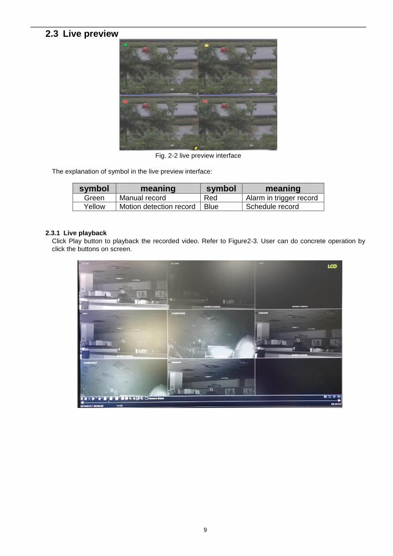
2.3 Live preview
Fig. 2-2 live preview interface
The explanation of symbol in the live preview interface:
symbol meaning symbol meaning Green Manual record Red Alarm in trigger record
Yellow Motion detection record Blue Schedule record
2.3.1 Live playback
Click Play button to playback the recorded video. Refer to Figure2-3. User can do concrete operation by
click the buttons on screen.
10
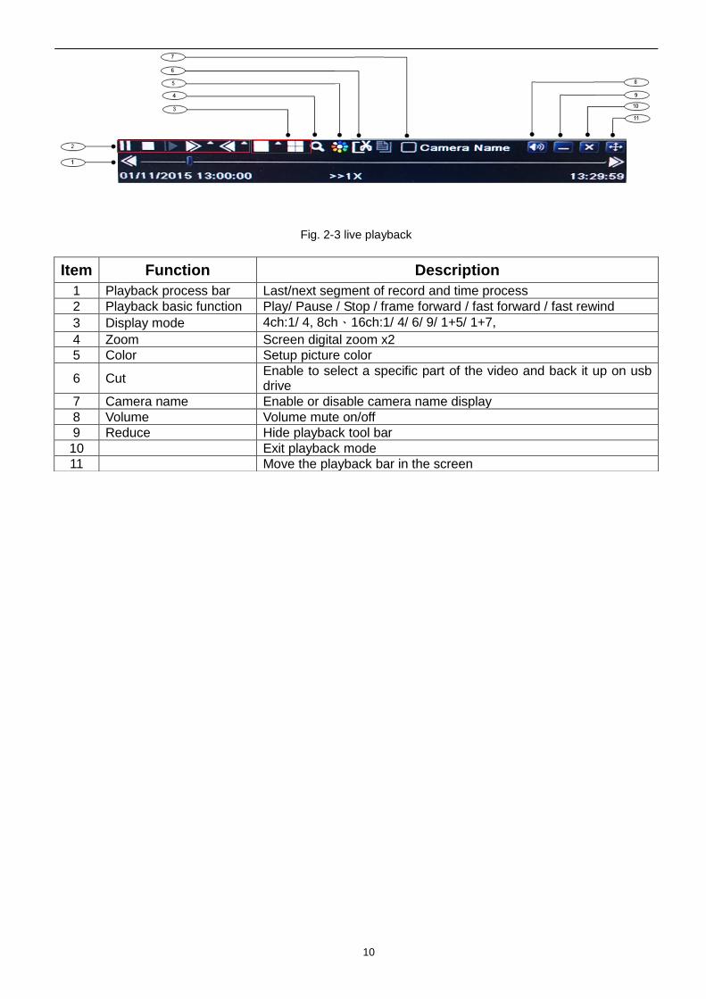
Fig. 2-3 live playback
Item Function Description
1 Playback process bar Last/next segment of record and time process
2 Playback basic function Play/ Pause / Stop / frame forward / fast forward / fast rewind
3 Display mode 4ch:1/ 4, 8ch、16ch:1/ 4/ 6/ 9/ 1+5/ 1+7,
4 Zoom Screen digital zoom x2
5 Color Setup picture color
6 Cut Enable to select a specific part of the video and back it up on usb drive
7 Camera name Enable or disable camera name display
8 Volume Volume mute on/off
9 Reduce Hide playback tool bar
10 Exit playback mode
11 Move the playback bar in the screen
11
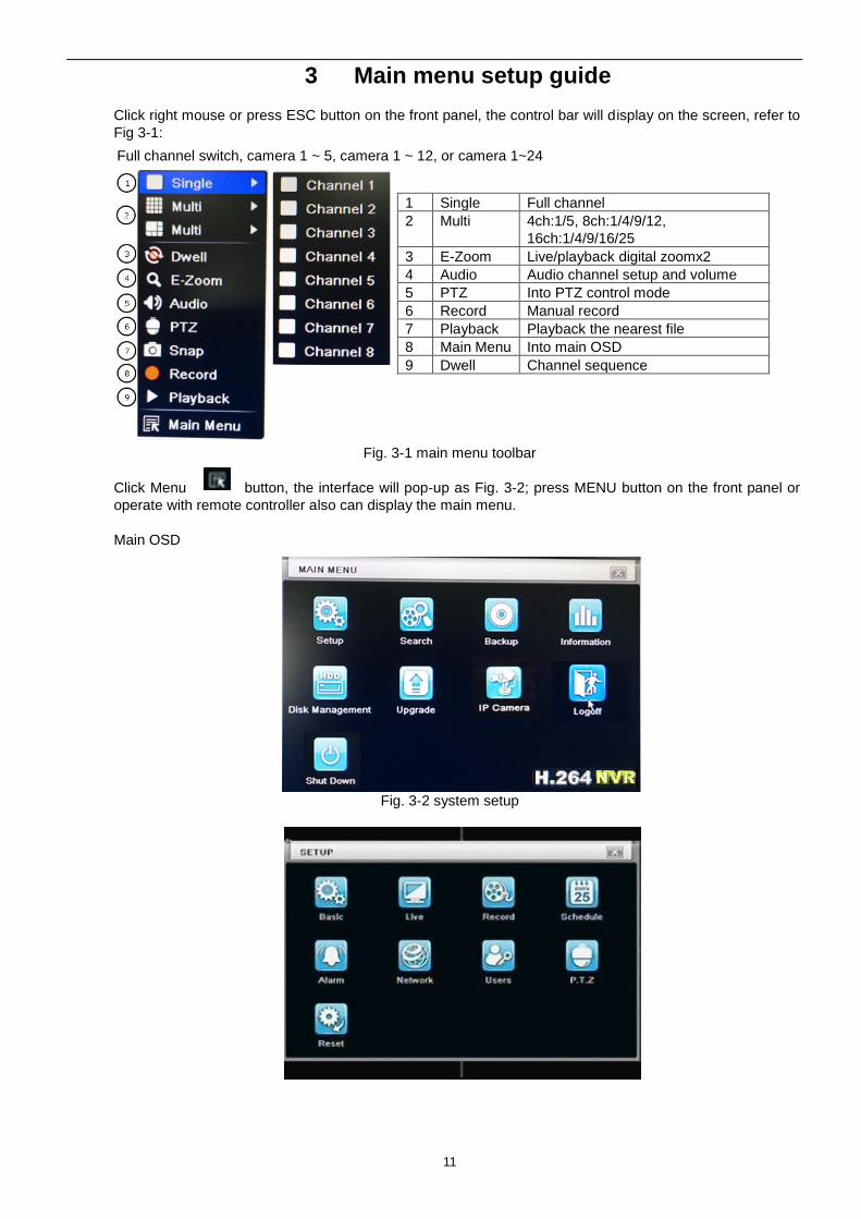
3 Main menu setup guide
Click right mouse or press ESC button on the front panel, the control bar will display on the screen, refer to
Fig 3-1:
1 Single Full channel
2 Multi 4ch:1/5, 8ch:1/4/9/12,
16ch:1/4/9/16/25
3 E-Zoom Live/playback digital zoomx2
4 Audio Audio channel setup and volume
5 PTZ Into PTZ control mode
6 Record Manual record
7 Playback Playback the nearest file
8 Main Menu Into main OSD
9 Dwell Channel sequence
Fig. 3-1 main menu toolbar
Click Menu button, the interface will pop-up as Fig. 3-2; press MENU button on the front panel or
operate with remote controller also can display the main menu.
Main OSD
Fig. 3-2 system setup
Full channel switch, camera 1 ~ 5, camera 1 ~ 12, or camera 1~24
12
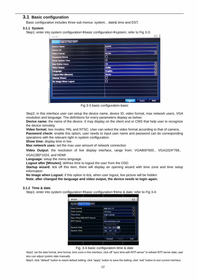
3.1 Basic configuration
Basic configuration includes three sub menus: system、date& time and DST.
3.1.1 System
Step1: enter into system configurationbasic configurationsystem; refer to Fig 3-3:
Fig 3-3 basic configuration-basic
Step2: in this interface user can setup the device name, device ID, video format, max network users, VGA
resolution and language. The definitions for every parameters display as below:
Device name: the name of the device. It may display on the client end or CMS that help user to recognize
the device remotely.
Video format: two modes: PAL and NTSC. User can select the video format according to that of camera.
Password check: enable this option, user needs to input user name and password can do corresponding
operations with the relevant right in system configuration.
Show time: display time in live.
Max network uses: set the max user amount of network connection
Video Output: the resolution of live display interface, range from: VGA800*600 、VGA1024*768、
VGA1280*1024, and HDMI
Language: setup the menu language.
Logout after [Minutes]: defines time to logout the user from the OSD
Startup wizard: tick off this item, there will display an opening wizard with time zone and time setup
information
No Image when Logout: if this option is tick, when user logout, live picture will be hidden
Note: after changed the language and video output, the device needs to login again.
3.1.2 Time & date
Step1: enter into system configurationbasic configurationtime & date; refer to Fig 3-4:
Fig. 3-4 basic configuration-time & date
Step2: set the date format, time format, time zone in this interface; click off “sync time with NTP server” to refresh NTP server date; user
also can adjust system date manually
Step3: click “default” button to resort default setting; click “apply” button to save the setting; click “exit” button to exit current interface.
13
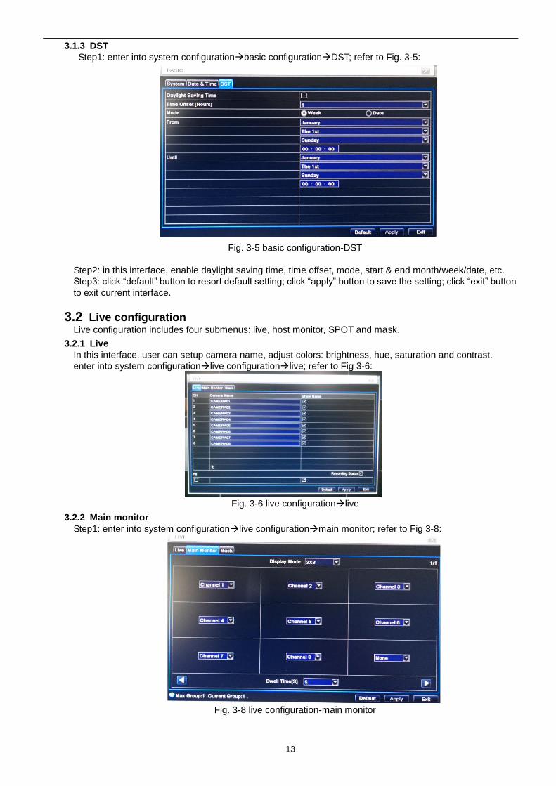
3.1.3 DST
Step1: enter into system configurationbasic configurationDST; refer to Fig. 3-5:
Fig. 3-5 basic configuration-DST
Step2: in this interface, enable daylight saving time, time offset, mode, start & end month/week/date, etc.
Step3: click “default” button to resort default setting; click “apply” button to save the setting; click “exit” button
to exit current interface.
3.2 Live configuration Live configuration includes four submenus: live, host monitor, SPOT and mask.
3.2.1 Live
In this interface, user can setup camera name, adjust colors: brightness, hue, saturation and contrast.
enter into system configurationlive configurationlive; refer to Fig 3-6:
Fig. 3-6 live configurationlive
3.2.2 Main monitor
Step1: enter into system configurationlive configurationmain monitor; refer to Fig 3-8:
Fig. 3-8 live configuration-main monitor
14
Step2: select split mode: 1×1、2×2、2×3、3×3、4×4 and channel
Step3: dwell time: the time interval for a certain dwell picture display switching to next dwell picture display
Step4: selected the split mode, then setup current picture group. Click button to setup the previous
channel groups of dwell picture, click button to set the latter channel groups of dwell picture.
Step5: click “default” button to resort default setting; click “apply” button to save the setting; click “exit” button
to exit current interface.
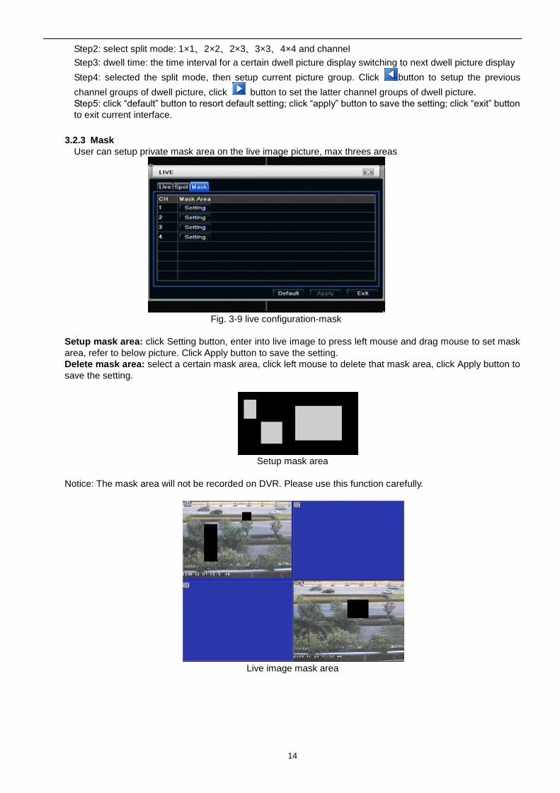
3.2.3 Mask
User can setup private mask area on the live image picture, max threes areas
Fig. 3-9 live configuration-mask
Setup mask area: click Setting button, enter into live image to press left mouse and drag mouse to set mask
area, refer to below picture. Click Apply button to save the setting.
Delete mask area: select a certain mask area, click left mouse to delete that mask area, click Apply button to
save the setting.
Setup mask area
Notice: The mask area will not be recorded on DVR. Please use this function carefully.
Live image mask area
15
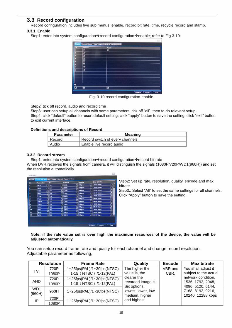
3.3 Record configuration Record configuration includes five sub menus: enable, record bit rate, time, recycle record and stamp.
3.3.1 Enable
Step1: enter into system configurationrecord configurationenable; refer to Fig 3-10:
Fig. 3-10 record configuration-enable
Step2: tick off record, audio and record time
Step3: user can setup all channels with same parameters, tick off “all”, then to do relevant setup.
Step4: click “default” button to resort default setting; click “apply” button to save the setting; click “exit” button
to exit current interface.
Definitions and descriptions of Record:
Parameter Meaning
Record Record switch of every channels
Audio Enable live record audio
3.3.2 Record stream
Step1: enter into system configurationrecord configurationrecord bit rate
When DVR receives the signals from camera, it will distinguish the signals (1080P/720P/WD1(960H)) and set
the resolution automatically.
Note: if the rate value set is over high the maximum resources of the device, the value will be
adjusted automatically.
You can setup record frame rate and quality for each channel and change record resolution. Adjustable parameter as following,
Resolution Frame Rate Quality Encode Max bitrate
TVI 720P 1~25fps(PAL)/1~30fps(NTSC) The higher the
value is, the clearer the recorded image is. Six options: lowest, lower, low, medium, higher and highest.
VBR and
CBR.
You shall adjust it subject to the actual network condition. 1536, 1792, 2048, 4096, 5120, 6144, 7168, 8192, 9216, 10240, 12288 kbps
1080P 1-15(NTSC)/1-12(PAL)
AHD 720P 1~25fps(PAL)/1~30fps(NTSC)
1080P 1-15(NTSC)/1-12(PAL)
WD1
(960H) 960H 1~25fps(PAL)/1~30fps(NTSC)
IP 720P
1~25fps(PAL)/1~30fps(NTSC) 1080P
Step2: Set up rate, resolution, quality, encode and max
bitrate
Step3.: Select “All” to set the same settings for all channels.
Click “Apply” button to save the setting.
16
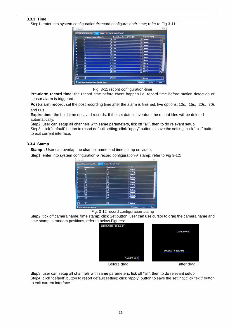
3.3.3 Time
Step1: enter into system configurationrecord configuration time; refer to Fig 3-11:
Fig. 3-11 record configuration-time
Pre-alarm record time: the record time before event happen i.e. record time before motion detection or
sensor alarm is triggered.
Post-alarm record: set the post recording time after the alarm is finished, five options: 10s、15s、20s、30s
and 60s.
Expire time: the hold time of saved records. If the set date is overdue, the record files will be deleted
automatically.
Step2: user can setup all channels with same parameters, tick off “all”, then to do relevant setup.
Step3: click “default” button to resort default setting; click “apply” button to save the setting; click “exit” button
to exit current interface.
3.3.4 Stamp
Stamp:User can overlap the channel name and time stamp on video.
Step1: enter into system configuration record configuration stamp; refer to Fig 3-12:
Fig. 3-12 record configuration-stamp
Step2: tick off camera name, time stamp; click Set button, user can use cursor to drag the camera name and
time stamp in random positions, refer to below Figures:
Before drag after drag
Step3: user can setup all channels with same parameters, tick off “all”, then to do relevant setup.
Step4: click “default” button to resort default setting; click “apply” button to save the setting; click “exit” button
to exit current interface.
17
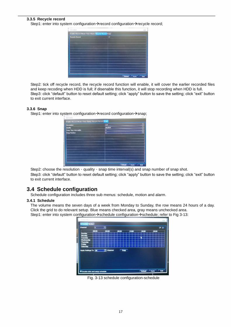
3.3.5 Recycle record
Step1: enter into system configurationrecord configurationrecycle record;
Step2: tick off recycle record, the recycle record function will enable, it will cover the earlier recorded files
and keep recoding when HDD is full; if disenable this function, it will stop recording when HDD is full.
Step3: click “default” button to reset default setting; click “apply” button to save the setting; click “exit” button
to exit current interface.
3.3.6 Snap
Step1: enter into system configurationrecord configurationsnap;
Step2: choose the resolution、quality、snap time interval(s) and snap number of snap shot.
Step3: click “default” button to reset default setting; click “apply” button to save the setting; click “exit” button
to exit current interface.
3.4 Schedule configuration Schedule configuration includes three sub menus: schedule, motion and alarm.
3.4.1 Schedule
The volume means the seven days of a week from Monday to Sunday, the row means 24 hours of a day.
Click the grid to do relevant setup. Blue means checked area, gray means unchecked area.
Step1: enter into system configurationschedule configurationschedule; refer to Fig 3-13:
Fig. 3-13 schedule configuration-schedule
18
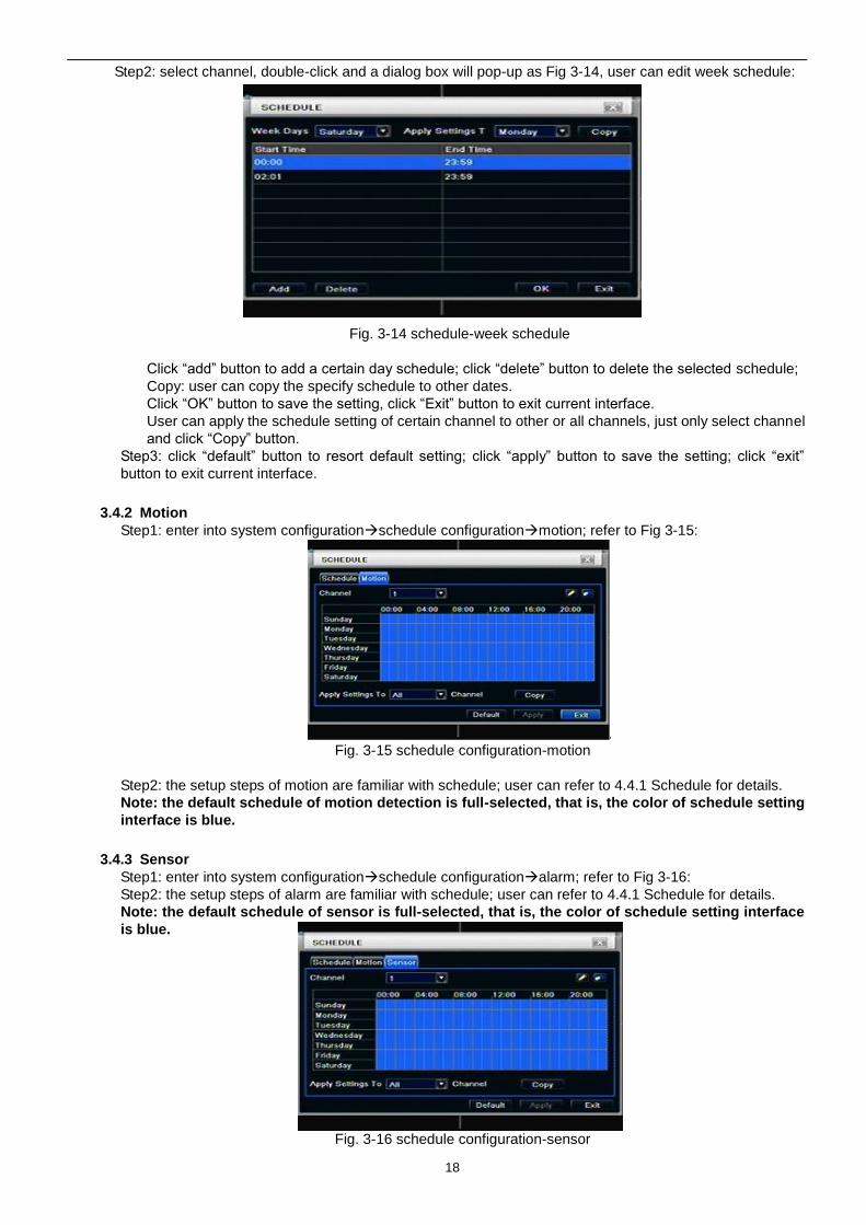
Step2: select channel, double-click and a dialog box will pop-up as Fig 3-14, user can edit week schedule:
Fig. 3-14 schedule-week schedule
Click “add” button to add a certain day schedule; click “delete” button to delete the selected schedule;
Copy: user can copy the specify schedule to other dates.
Click “OK” button to save the setting, click “Exit” button to exit current interface.
User can apply the schedule setting of certain channel to other or all channels, just only select channel
and click “Copy” button.
Step3: click “default” button to resort default setting; click “apply” button to save the setting; click “exit”
button to exit current interface.
3.4.2 Motion
Step1: enter into system configurationschedule configurationmotion; refer to Fig 3-15:
Fig. 3-15 schedule configuration-motion
Step2: the setup steps of motion are familiar with schedule; user can refer to 4.4.1 Schedule for details.
Note: the default schedule of motion detection is full-selected, that is, the color of schedule setting
interface is blue.
3.4.3 Sensor
Step1: enter into system configurationschedule configurationalarm; refer to Fig 3-16:
Step2: the setup steps of alarm are familiar with schedule; user can refer to 4.4.1 Schedule for details.
Note: the default schedule of sensor is full-selected, that is, the color of schedule setting interface
is blue.
Fig. 3-16 schedule configuration-sensor
19
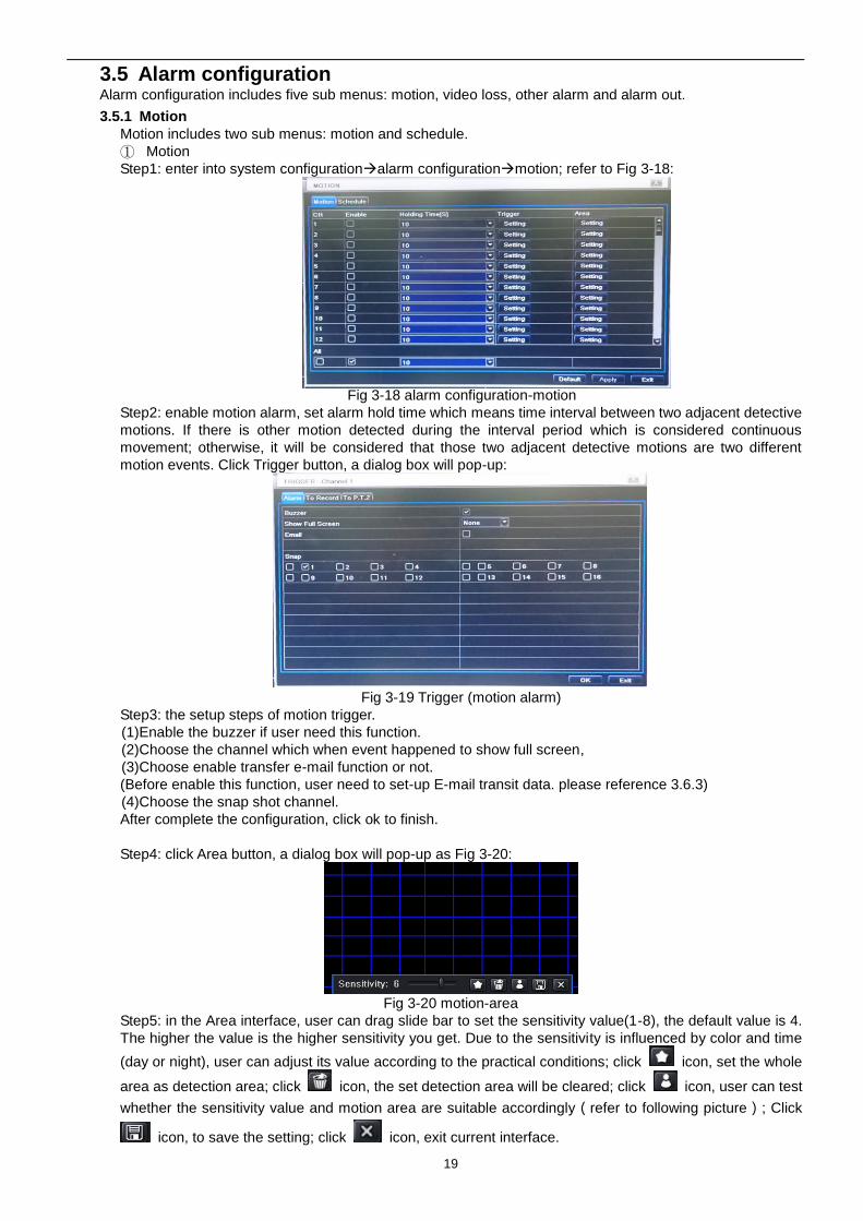
3.5 Alarm configuration Alarm configuration includes five sub menus: motion, video loss, other alarm and alarm out.
3.5.1 Motion
Motion includes two sub menus: motion and schedule.
① Motion
Step1: enter into system configurationalarm configurationmotion; refer to Fig 3-18:
Fig 3-18 alarm configuration-motion
Step2: enable motion alarm, set alarm hold time which means time interval between two adjacent detective
motions. If there is other motion detected during the interval period which is considered continuous
movement; otherwise, it will be considered that those two adjacent detective motions are two different
motion events. Click Trigger button, a dialog box will pop-up:
Fig 3-19 Trigger (motion alarm)
Step3: the setup steps of motion trigger.
(1)Enable the buzzer if user need this function.
(2)Choose the channel which when event happened to show full screen,
(3)Choose enable transfer e-mail function or not.
(Before enable this function, user need to set-up E-mail transit data. please reference 3.6.3)
(4)Choose the snap shot channel.
After complete the configuration, click ok to finish.
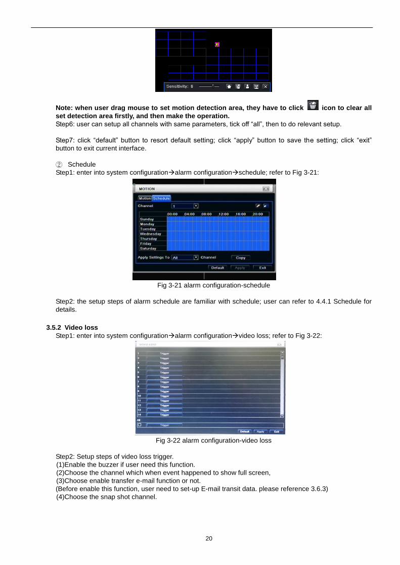
Step4: click Area button, a dialog box will pop-up as Fig 3-20:
Fig 3-20 motion-area
Step5: in the Area interface, user can drag slide bar to set the sensitivity value(1-8), the default value is 4.
The higher the value is the higher sensitivity you get. Due to the sensitivity is influenced by color and time
(day or night), user can adjust its value according to the practical conditions; click icon, set the whole
area as detection area; click icon, the set detection area will be cleared; click icon, user can test
whether the sensitivity value and motion area are suitable accordingly(refer to following picture); Click
icon, to save the setting; click icon, exit current interface.
20
Note: when user drag mouse to set motion detection area, they have to click icon to clear all
set detection area firstly, and then make the operation.
Step6: user can setup all channels with same parameters, tick off “all”, then to do relevant setup.
Step7: click “default” button to resort default setting; click “apply” button to save the setting; click “exit”
button to exit current interface.
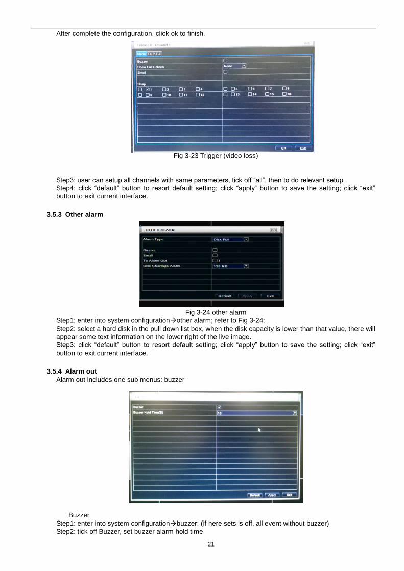
② Schedule
Step1: enter into system configurationalarm configurationschedule; refer to Fig 3-21:
Fig 3-21 alarm configuration-schedule
Step2: the setup steps of alarm schedule are familiar with schedule; user can refer to 4.4.1 Schedule for
details.
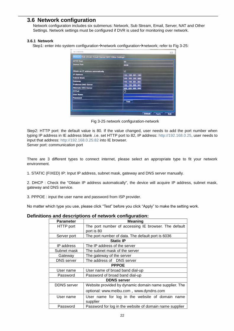
3.5.2 Video loss
Step1: enter into system configurationalarm configurationvideo loss; refer to Fig 3-22:
Fig 3-22 alarm configuration-video loss
Step2: Setup steps of video loss trigger.
(1)Enable the buzzer if user need this function.
(2)Choose the channel which when event happened to show full screen,
(3)Choose enable transfer e-mail function or not.
(Before enable this function, user need to set-up E-mail transit data. please reference 3.6.3)
(4)Choose the snap shot channel.
21
After complete the configuration, click ok to finish.
Fig 3-23 Trigger (video loss)
Step3: user can setup all channels with same parameters, tick off “all”, then to do relevant setup.
Step4: click “default” button to resort default setting; click “apply” button to save the setting; click “exit”
button to exit current interface.
3.5.3 Other alarm
Fig 3-24 other alarm
Step1: enter into system configurationother alarm; refer to Fig 3-24:
Step2: select a hard disk in the pull down list box, when the disk capacity is lower than that value, there will
appear some text information on the lower right of the live image.
Step3: click “default” button to resort default setting; click “apply” button to save the setting; click “exit”
button to exit current interface.
3.5.4 Alarm out
Alarm out includes one sub menus: buzzer
Buzzer
Step1: enter into system configurationbuzzer; (if here sets is off, all event without buzzer)
Step2: tick off Buzzer, set buzzer alarm hold time
22
3.6 Network configuration Network configuration includes six submenus: Network, Sub Stream, Email, Server, NAT and Other
Settings. Network settings must be configured if DVR is used for monitoring over network.
3.6.1 Network
Step1: enter into system configurationnetwork configurationnetwork; refer to Fig 3-25:
Fig 3-25 network configuration-network
Step2: HTTP port: the default value is 80. If the value changed, user needs to add the port number when
typing IP address in IE address blank .i.e. set HTTP port to 82, IP address: http://192.168.0.25, user needs to
input that address: http://192.168.0.25:82 into IE browser.
Server port: communication port
There are 3 different types to connect internet, please select an appropriate type to fit your network
environment.
1. STATIC (FIXED) IP: Input IP address, subnet mask, gateway and DNS server manually.
2. DHCP : Check the "Obtain IP address automatically", the device will acquire IP address, subnet mask,
gateway and DNS service.
3. PPPOE : input the user name and password from ISP provider.
No matter which type you use, please click “Test” before you click “Apply” to make the setting work.
Definitions and descriptions of network configuration: Parameter Meaning
HTTP port The port number of accessing IE browser. The default
port is 80
Server port The port number of data. The default port is 6036
Static IP
IP address The IP address of the server
Subnet mask The subnet mask of the server
Gateway The gateway of the server
DNS server The address of DNS server
PPPOE
User name User name of broad band dial-up
Password Password of broad band dial-up
DDNS server
DDNS server Website provided by dynamic domain name supplier. The
optional: www.meibu.com,www.dyndns.com
User name User name for log in the website of domain name
supplier
Password Password for log in the website of domain name supplier
23
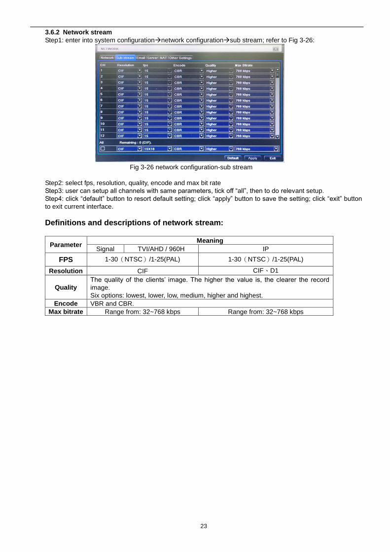
3.6.2 Network stream
Step1: enter into system configurationnetwork configurationsub stream; refer to Fig 3-26:
Fig 3-26 network configuration-sub stream
Step2: select fps, resolution, quality, encode and max bit rate
Step3: user can setup all channels with same parameters, tick off “all”, then to do relevant setup.
Step4: click “default” button to resort default setting; click “apply” button to save the setting; click “exit” button
to exit current interface.
Definitions and descriptions of network stream:
Parameter Meaning
Signal TVI/AHD / 960H IP
FPS 1-30(NTSC)/1-25(PAL) 1-30(NTSC)/1-25(PAL)
Resolution CIF CIF、D1
Quality
The quality of the clients’ image. The higher the value is, the clearer the record
image.
Six options: lowest, lower, low, medium, higher and highest.
Encode VBR and CBR.
Max bitrate Range from: 32~768 kbps Range from: 32~768 kbps
24
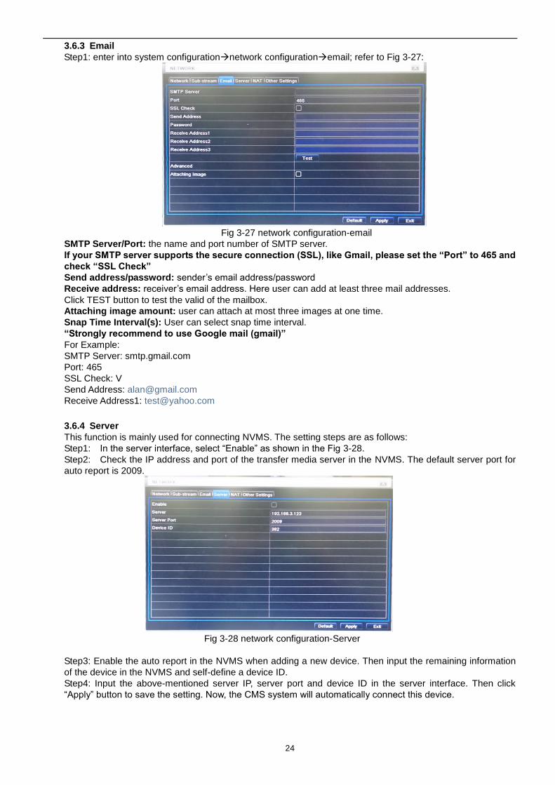
3.6.3 Email
Step1: enter into system configurationnetwork configurationemail; refer to Fig 3-27:
Fig 3-27 network configuration-email
SMTP Server/Port: the name and port number of SMTP server.
If your SMTP server supports the secure connection (SSL), like Gmail, please set the “Port” to 465 and
check “SSL Check”
Send address/password: sender’s email address/password
Receive address: receiver’s email address. Here user can add at least three mail addresses.
Click TEST button to test the valid of the mailbox.
Attaching image amount: user can attach at most three images at one time.
Snap Time Interval(s): User can select snap time interval.
“Strongly recommend to use Google mail (gmail)”
For Example:
SMTP Server: smtp.gmail.com
Port: 465
SSL Check: V
Send Address: [email protected]
Receive Address1: [email protected]
3.6.4 Server
This function is mainly used for connecting NVMS. The setting steps are as follows:
Step1: In the server interface, select “Enable” as shown in the Fig 3-28.
Step2: Check the IP address and port of the transfer media server in the NVMS. The default server port for
auto report is 2009.
Fig 3-28 network configuration-Server
Step3: Enable the auto report in the NVMS when adding a new device. Then input the remaining information
of the device in the NVMS and self-define a device ID.
Step4: Input the above-mentioned server IP, server port and device ID in the server interface. Then click
“Apply” button to save the setting. Now, the CMS system will automatically connect this device.
25
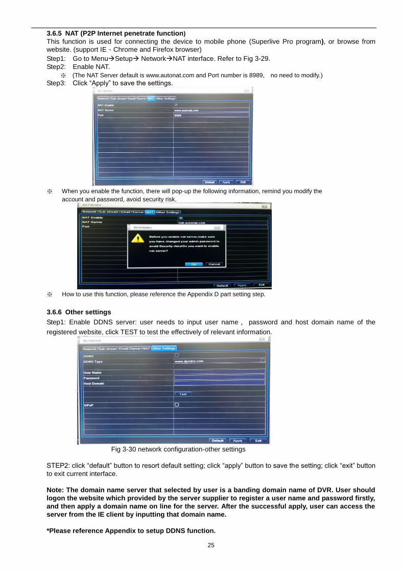
3.6.5 NAT (P2P Internet penetrate function)
This function is used for connecting the device to mobile phone (Superlive Pro program), or browse from
website. (support IE、Chrome and Firefox browser)
Step1: Go to MenuSetup NetworkNAT interface. Refer to Fig 3-29.
Step2: Enable NAT.
※ (The NAT Server default is www.autonat.com and Port number is 8989, no need to modify.)
Step3: Click “Apply” to save the settings.
※ When you enable the function, there will pop-up the following information, remind you modify the
account and password, avoid security risk.
※ How to use this function, please reference the Appendix D part setting step.
3.6.6 Other settings
Step1: Enable DDNS server: user needs to input user name, password and host domain name of the
registered website, click TEST to test the effectively of relevant information.
Fig 3-30 network configuration-other settings
STEP2: click “default” button to resort default setting; click “apply” button to save the setting; click “exit” button
to exit current interface.
Note: The domain name server that selected by user is a banding domain name of DVR. User should
logon the website which provided by the server supplier to register a user name and password firstly,
and then apply a domain name on line for the server. After the successful apply, user can access the
server from the IE client by inputting that domain name.
*Please reference Appendix to setup DDNS function.
26
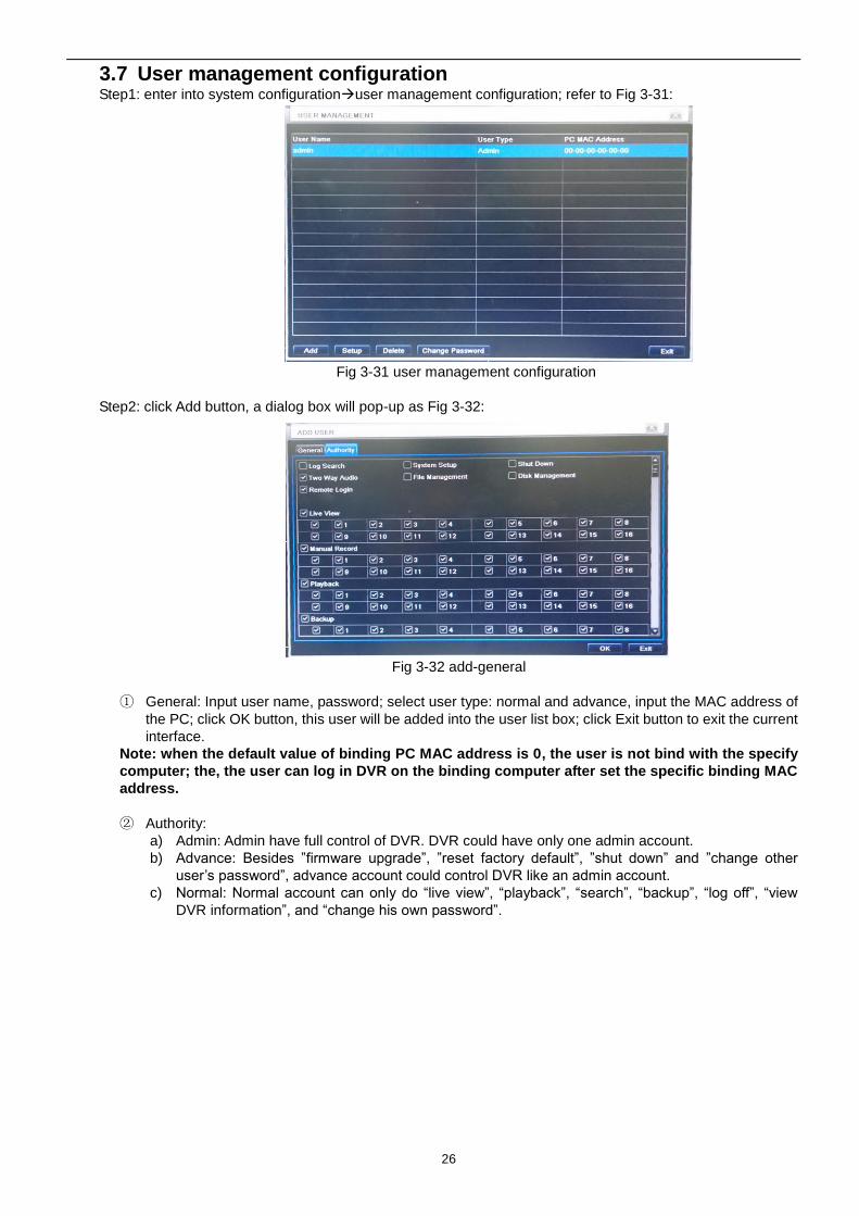
3.7 User management configuration Step1: enter into system configurationuser management configuration; refer to Fig 3-31:
Fig 3-31 user management configuration
Step2: click Add button, a dialog box will pop-up as Fig 3-32:
Fig 3-32 add-general
① General: Input user name, password; select user type: normal and advance, input the MAC address of
the PC; click OK button, this user will be added into the user list box; click Exit button to exit the current
interface.
Note: when the default value of binding PC MAC address is 0, the user is not bind with the specify
computer; the, the user can log in DVR on the binding computer after set the specific binding MAC
address.
② Authority:
a) Admin: Admin have full control of DVR. DVR could have only one admin account.
b) Advance: Besides ”firmware upgrade”, ”reset factory default”, ”shut down” and ”change other
user’s password”, advance account could control DVR like an admin account.
c) Normal: Normal account can only do “live view”, “playback”, “search”, “backup”, “log off”, “view
DVR information”, and “change his own password”.
27
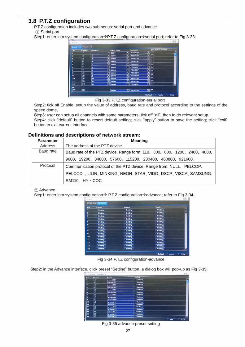
3.8 P.T.Z configuration P.T.Z configuration includes two submenus: serial port and advance
① Serial port
Step1: enter into system configurationP.T.Z configurationserial port; refer to Fig 3-33:
Fig 3-33 P.T.Z configuration-serial port
Step2: tick off Enable, setup the value of address, baud rate and protocol according to the settings of the
speed dome.
Step3: user can setup all channels with same parameters, tick off “all”, then to do relevant setup.
Step4: click “default” button to resort default setting; click “apply” button to save the setting; click “exit”
button to exit current interface.
Definitions and descriptions of network stream:
② Advance
Step1: enter into system configuration P.T.Z configurationadvance; refer to Fig 3-34:
Fig 3-34 P.T.Z configuration-advance
Step2: in the Advance interface, click preset “Setting” button, a dialog box will pop-up as Fig 3-35:
Fig 3-35 advance-preset setting
Parameter Meaning
Address The address of the PTZ device
Baud rate Baud rate of the PTZ device. Range form: 110、300、600、1200、2400、4800、
9600、19200、34800、57600、115200、230400、460800、921600.
Protocol Communication protocol of the PTZ device. Range from: NULL、PELCOP、
PELCOD 、LILIN、MINKING、NEON、STAR、VIDO、DSCP、VISCA、SAMSUNG、
RM110、HY、COC
28
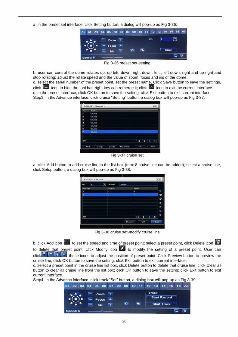
a. in the preset set interface, click Setting button, a dialog will pop-up as Fig 3-36:
Fig 3-36 preset set-setting
b. user can control the dome rotates up, up left, down, right down, left , left down, right and up right and
stop rotating; adjust the rotate speed and the value of zoom, focus and iris of the dome;
c. select the serial number of the preset point, set the preset name. Click Save button to save the settings,
click icon to hide the tool bar, right-key can remerge it; click icon to exit the current interface.
d. in the preset interface, click OK button to save the setting; click Exit button to exit current interface.
Step3: in the Advance interface, click cruise “Setting” button, a dialog box will pop-up as Fig 3-37:
Fig 3-37 cruise set
a. click Add button to add cruise line in the list box (max 8 cruise line can be added); select a cruise line,
click Setup button, a dialog box will pop-up as Fig 3-38:
Fig 3-38 cruise set-modify cruise line
b. click Add icon to set the speed and time of preset point; select a preset point, click Delete icon
to delete that preset point; click Modify icon to modify the setting of a preset point. User can
click those icons to adjust the position of preset point. Click Preview button to preview the
cruise line, click OK button to save the setting, click Exit button to exit current interface.
c. select a preset point in the cruise line list box, click Delete button to delete that cruise line; click Clear all
button to clear all cruise line from the list box; click OK button to save the setting; click Exit button to exit
current interface.
Step4: in the Advance interface, click track “Set” button, a dialog box will pop-up as Fig 3-39:
29
Fig 3-39 track set
a. user can control the dome rotates up, up left, down, right down, left, left down, right and up right and stop
rotating; adjust the rotate speed and the value of zoom, focus and iris of the dome; click Start Record
button to record the move track of PTZ, click this button again can stop record; click Start track button to
play recorded track, click this button again can stop play.;
b. click icon to hide the tool bar, right-key can remerge it; click icon to exit the current interface.
Step5: in the Advance interface, click “default” button to resort default setting; click “apply” button to save
the setting; click “exit” button to exit current interface.
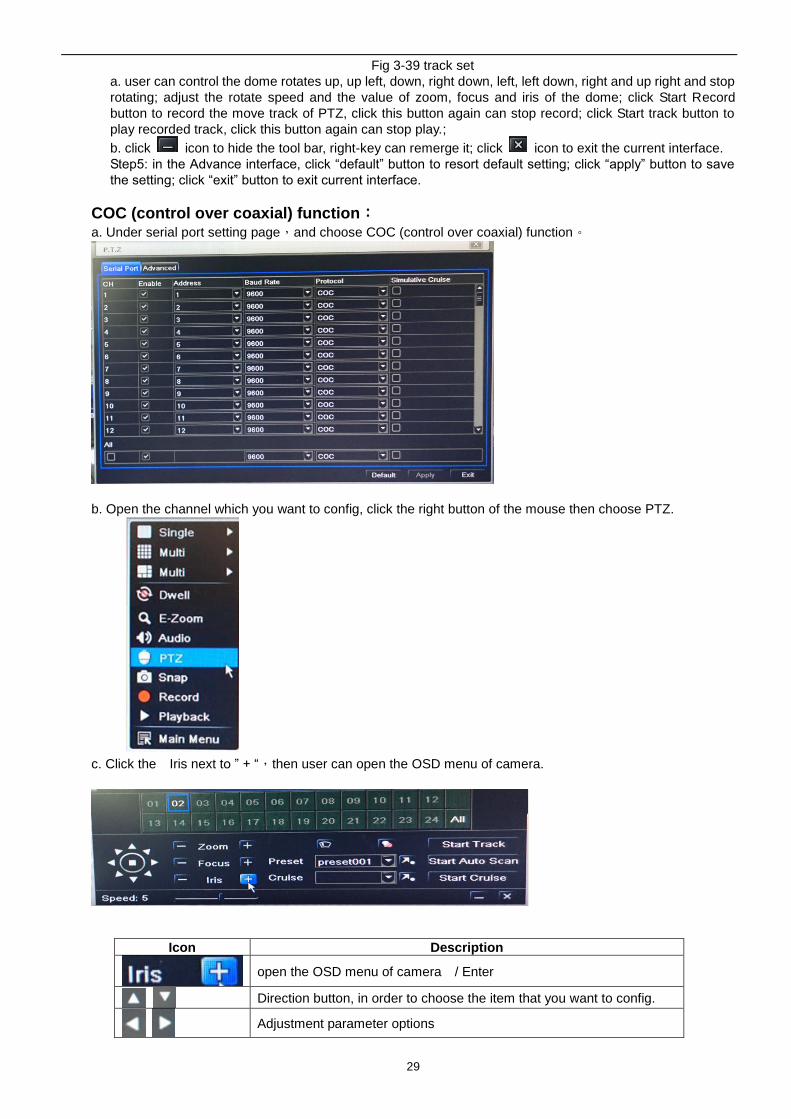
COC (control over coaxial) function: a. Under serial port setting page,and choose COC (control over coaxial) function。
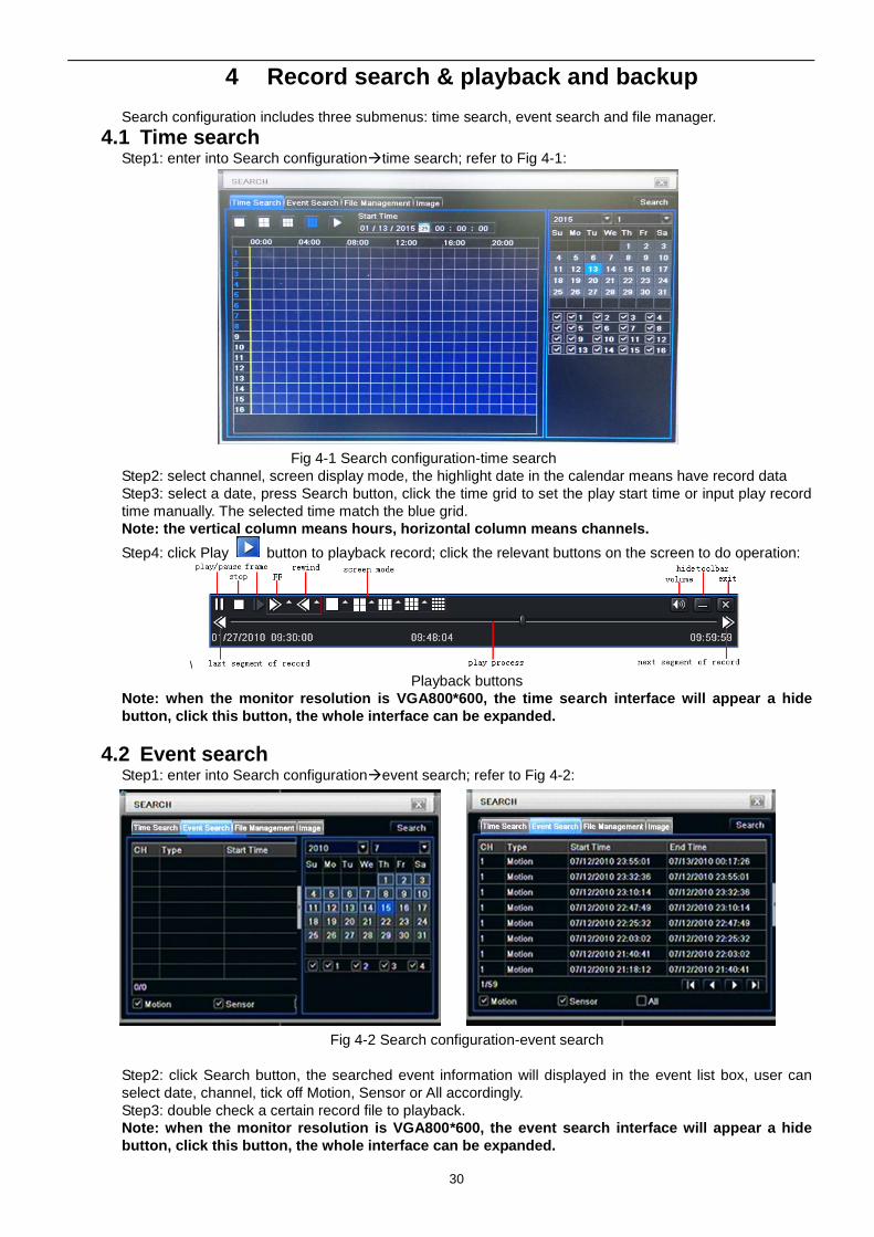
b. Open the channel which you want to config, click the right button of the mouse then choose PTZ.
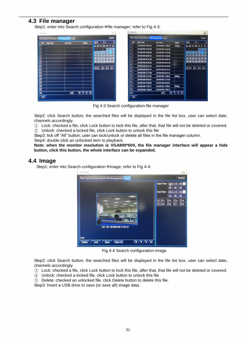
c. Click the Iris next to ” + “,then user can open the OSD menu of camera.
Icon Description
open the OSD menu of camera / Enter
Direction button, in order to choose the item that you want to config.
Adjustment parameter options
30
4 Record search & playback and backup
Search configuration includes three submenus: time search, event search and file manager.
4.1 Time search Step1: enter into Search configurationtime search; refer to Fig 4-1:
Fig 4-1 Search configuration-time search
Step2: select channel, screen display mode, the highlight date in the calendar means have record data
Step3: select a date, press Search button, click the time grid to set the play start time or input play record
time manually. The selected time match the blue grid.
Note: the vertical column means hours, horizontal column means channels.
Step4: click Play button to playback record; click the relevant buttons on the screen to do operation:
\ Playback buttons
Note: when the monitor resolution is VGA800*600, the time search interface will appear a hide
button, click this button, the whole interface can be expanded.
4.2 Event search Step1: enter into Search configurationevent search; refer to Fig 4-2:
Fig 4-2 Search configuration-event search
Step2: click Search button, the searched event information will displayed in the event list box, user can
select date, channel, tick off Motion, Sensor or All accordingly.
Step3: double check a certain record file to playback.
Note: when the monitor resolution is VGA800*600, the event search interface will appear a hide
button, click this button, the whole interface can be expanded.
31
4.3 File manager Step1: enter into Search configurationfile manager; refer to Fig 4-3:
Fig 4-3 Search configuration-file manager
Step2: click Search button, the searched files will be displayed in the file list box, user can select date,
channels accordingly.
① Lock: checked a file, click Lock button to lock this file, after that, that file will not be deleted or covered.
② Unlock: checked a locked file, click Lock button to unlock this file
Step3: tick off “All” button; user can lock/unlock or delete all files in the file manager column.
Step4: double click an unlocked item to playback.
Note: when the monitor resolution is VGA800*600, the file manager interface will appear a hide
button, click this button, the whole interface can be expanded.
4.4 Image Step1: enter into Search configurationimage; refer to Fig 4-4:
Fig 4-4 Search configuration-image
Step2: click Search button, the searched files will be displayed in the file list box, user can select date,
channels accordingly.
③ Lock: checked a file, click Lock button to lock this file, after that, that file will not be deleted or covered.
④ Unlock: checked a locked file, click Lock button to unlock this file
⑤ Delete: checked an unlocked file, click Delete button to delete this file.
Step3: Insert a USB drive to save (or save all) image data.
32
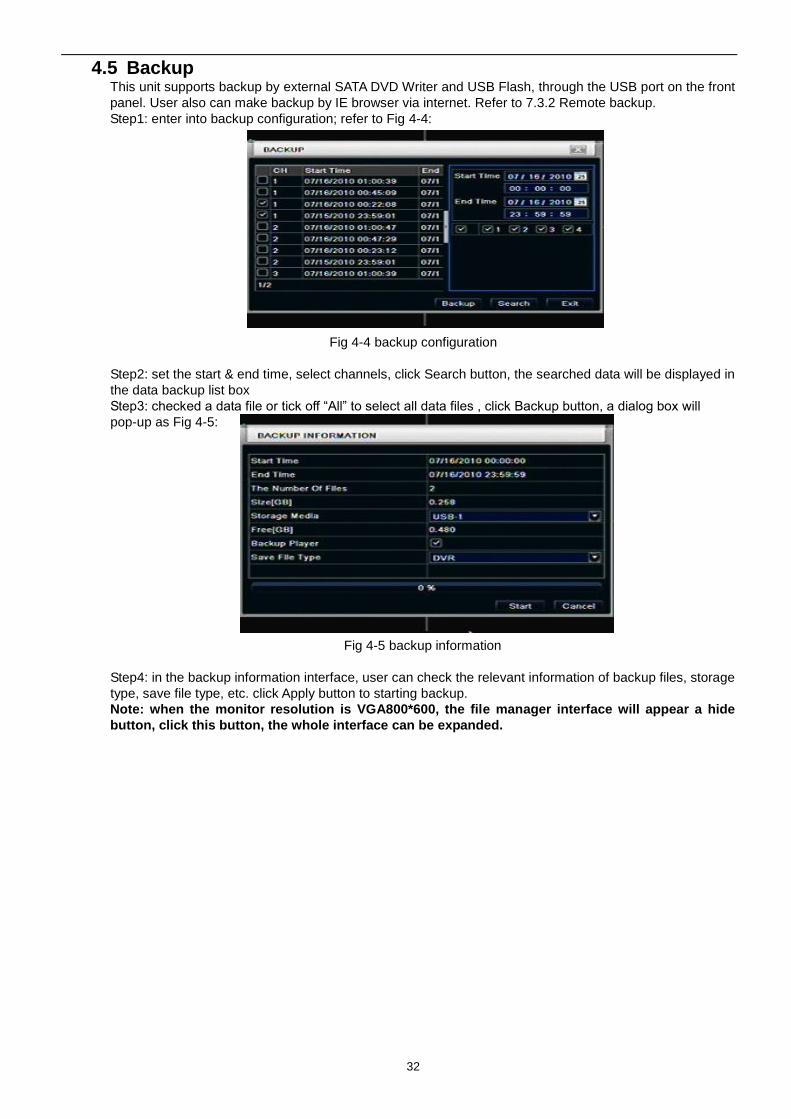
4.5 Backup This unit supports backup by external SATA DVD Writer and USB Flash, through the USB port on the front
panel. User also can make backup by IE browser via internet. Refer to 7.3.2 Remote backup.
Step1: enter into backup configuration; refer to Fig 4-4:
Fig 4-4 backup configuration
Step2: set the start & end time, select channels, click Search button, the searched data will be displayed in
the data backup list box
Step3: checked a data file or tick off “All” to select all data files , click Backup button, a dialog box will
pop-up as Fig 4-5:
Fig 4-5 backup information
Step4: in the backup information interface, user can check the relevant information of backup files, storage
type, save file type, etc. click Apply button to starting backup.
Note: when the monitor resolution is VGA800*600, the file manager interface will appear a hide
button, click this button, the whole interface can be expanded.
33
5 Manage DVR
5.1 Check system information Check system information includes five submenus: system, event, log, network and online user.
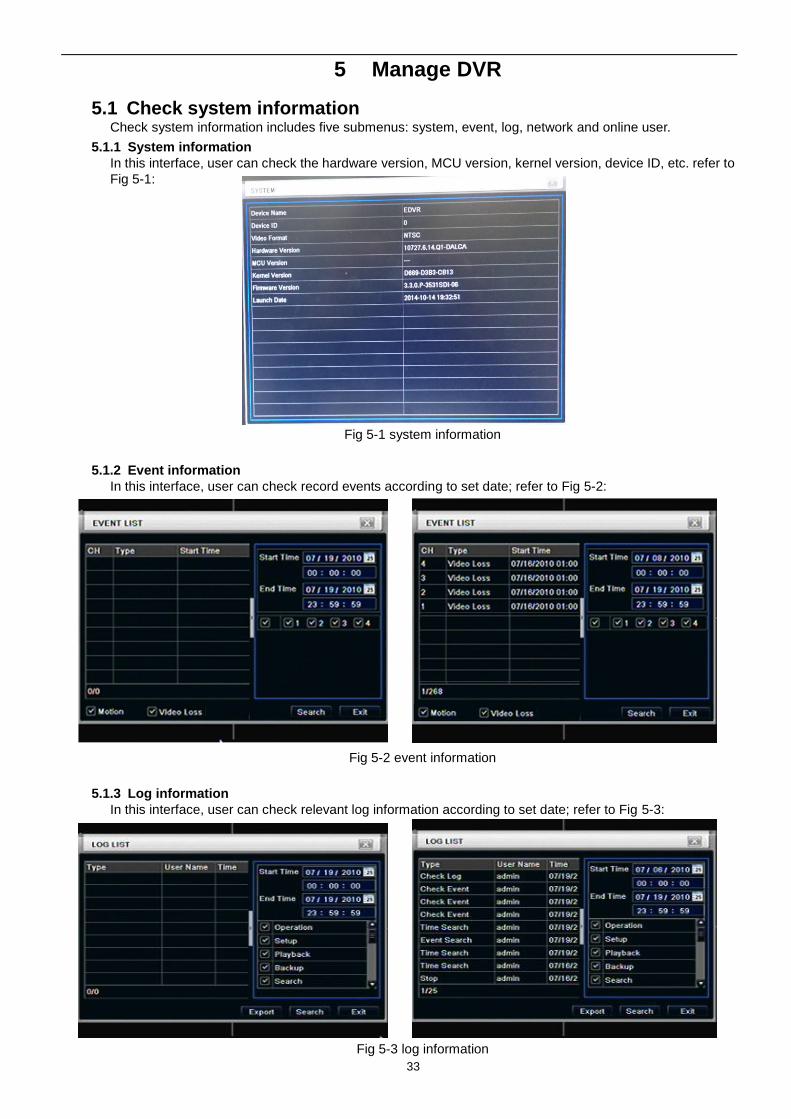
5.1.1 System information
In this interface, user can check the hardware version, MCU version, kernel version, device ID, etc. refer to
Fig 5-1:
Fig 5-1 system information
5.1.2 Event information
In this interface, user can check record events according to set date; refer to Fig 5-2:
Fig 5-2 event information
5.1.3 Log information
In this interface, user can check relevant log information according to set date; refer to Fig 5-3:
Fig 5-3 log information
34
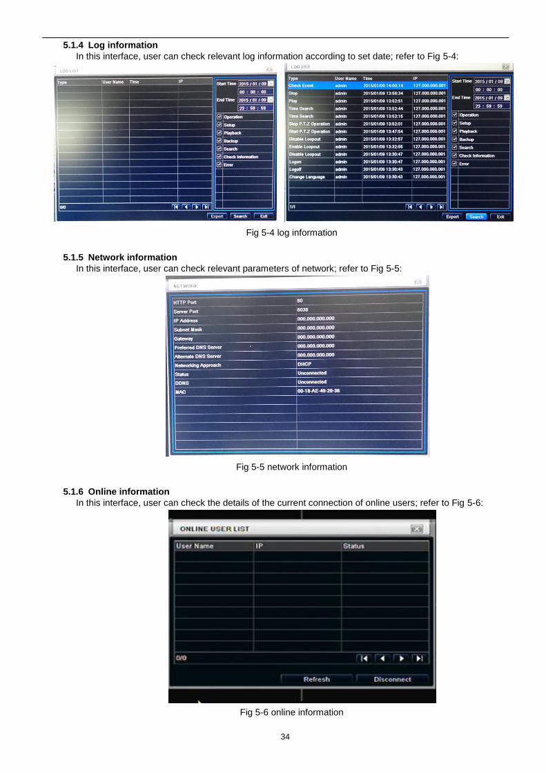
5.1.4 Log information
In this interface, user can check relevant log information according to set date; refer to Fig 5-4:
Fig 5-4 log information
5.1.5 Network information
In this interface, user can check relevant parameters of network; refer to Fig 5-5:
Fig 5-5 network information
5.1.6 Online information
In this interface, user can check the details of the current connection of online users; refer to Fig 5-6:
Fig 5-6 online information
35
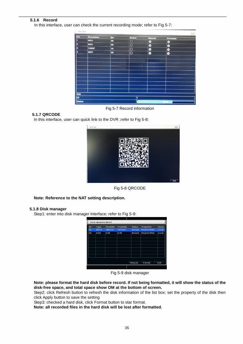
5.1.6 Record
In this interface, user can check the current recording mode; refer to Fig 5-7:
Fig 5-7 Record information
5.1.7 QRCODE
In this interface, user can quick link to the DVR ;refer to Fig 5-8:
Fig 5-8 QRCODE
Note: Reference to the NAT setting description.
5.1.8 Disk manager
Step1: enter into disk manager interface; refer to Fig 5-9:
Fig 5-9 disk manager
Note: please format the hard disk before record. If not being formatted, it will show the status of the
disk-free space, and total space show OM at the bottom of screen.
Step2: click Refresh button to refresh the disk information of the list box; set the property of the disk then
click Apply button to save the setting
Step3: checked a hard disk, click Format button to star format.
Note: all recorded files in the hard disk will be lost after formatted.
36
5.1.9 Upgrade
At present, it only supports USB update. Get the firmware from your vendor when there is a new firmware
version, and make sure it is corresponding with the DVR. User can check the USB information in Disk
manager.
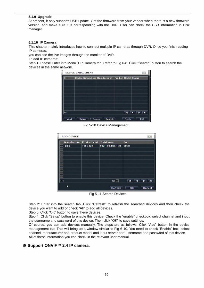
5.1.10 IP Camera
This chapter mainly introduces how to connect multiple IP cameras through DVR. Once you finish adding
IP cameras,
you can see the live images through the monitor of DVR.
To add IP cameras:
Step 1: Please Enter into MenuIP Camera tab. Refer to Fig 6-8. Click “Search” button to search the
devices in the same network.
Fig 5-10 Device Management
Fig 5-11 Search Devices
Step 2: Enter into the search tab. Click “Refresh” to refresh the searched devices and then check the
device you want to add or check “All” to add all devices.
Step 3: Click “OK” button to save these devices.
Step 4: Click “Setup” button to enable this device. Check the “enable” checkbox, select channel and input
the username and password of this device. Then click “OK” to save settings.
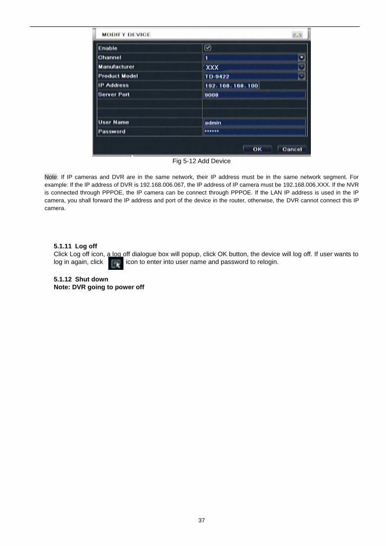
Of course, you can add devices manually. The steps are as follows: Click “Add” button in the device
management tab. This will bring up a window similar to Fig 6-10. You need to check “Enable” box, select
channel, manufacturer and product model and input server port, username and password of this device.
All of these information you can check in the relevant user manual.
※ Support ONVIF™ 2.4 IP camera.
37
Fig 5-12 Add Device
Note: If IP cameras and DVR are in the same network, their IP address must be in the same network segment. For
example: If the IP address of DVR is 192.168.006.067, the IP address of IP camera must be 192.168.006.XXX. If the NVR
is connected through PPPOE, the IP camera can be connect through PPPOE. If the LAN IP address is used in the IP
camera, you shall forward the IP address and port of the device in the router, otherwise, the DVR cannot connect this IP
camera.
5.1.11 Log off
Click Log off icon, a log off dialogue box will popup, click OK button, the device will log off. If user wants to
log in again, click icon to enter into user name and password to relogin.
5.1.12 Shut down
Note: DVR going to power off
38
6 Remote Surveillance
6.1 Accessing DVR If making remote view, the DVR must connect with LAN or internet. Then enable network server in the unit.
Please refer to 4.6 Network Configuration.
This unit supports IE browser, without any client software installed. It supports Win 7, XP and Vista.
6.1.1 On LAN
Step1: Input IP address, Subnet, Gateway. If using DHCP, please enable DHCP in both the DVR and router.
Enter Menu—Information—Network, and user can check the network configuration of DVR.
Step2: Enter Video to set network video parameters like resolution, frame rate etc.
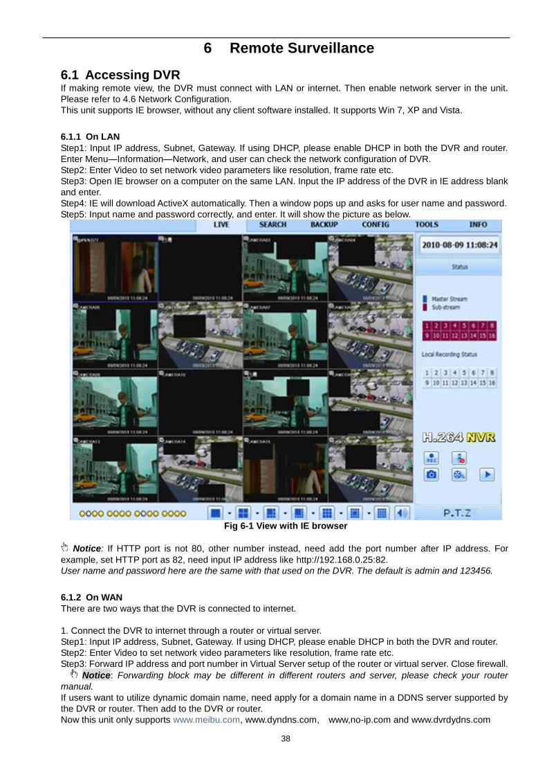
Step3: Open IE browser on a computer on the same LAN. Input the IP address of the DVR in IE address blank
and enter.
Step4: IE will download ActiveX automatically. Then a window pops up and asks for user name and password.
Step5: Input name and password correctly, and enter. It will show the picture as below.
Fig 6-1 View with IE browser
Notice: If HTTP port is not 80, other number instead, need add the port number after IP address. For
example, set HTTP port as 82, need input IP address like http://192.168.0.25:82.
User name and password here are the same with that used on the DVR. The default is admin and 123456.
6.1.2 On WAN
There are two ways that the DVR is connected to internet.
1. Connect the DVR to internet through a router or virtual server.
Step1: Input IP address, Subnet, Gateway. If using DHCP, please enable DHCP in both the DVR and router.
Step2: Enter Video to set network video parameters like resolution, frame rate etc.
Step3: Forward IP address and port number in Virtual Server setup of the router or virtual server. Close firewall.
Notice: Forwarding block may be different in different routers and server, please check your router
manual.
If users want to utilize dynamic domain name, need apply for a domain name in a DDNS server supported by
the DVR or router. Then add to the DVR or router.
Now this unit only supports www.meibu.com, www.dyndns.com, www,no-ip.com and www.dvrdydns.com
39
About the router, please check in the router manual.
Step5: Open IE browser, input IP address, or dynamic domain name and enter. If HTTP port is not 80, add the
port number after IP address or domain name.
Step6: IE will download ActiveX automatically. Then a window pops up and asks for user name and password.
Step7: Input name and password correctly, and enter to view.
Notice: If you cannot download and install ActiveX, please refer to “FAQ” Q7.
2. Connect the DVR to internet directly.
Step1: Input IP address, Subnet, Gateway gotten from your ISP. If using ADSL, please input user name and
password, and click OK. The DVR will connect the server and show “connection succeeds”.
Step2: The following steps are the same as STEP4-7 of the connection way above.
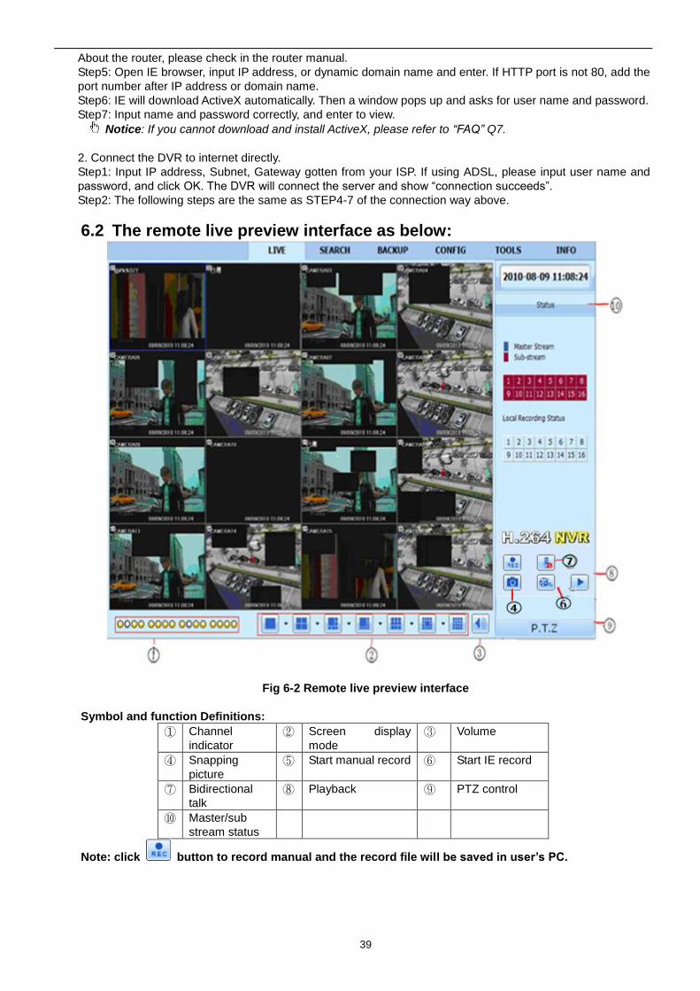
6.2 The remote live preview interface as below:
Fig 6-2 Remote live preview interface
Symbol and function Definitions:
① Channel
indicator
② Screen display
mode
③ Volume
④ Snapping
picture
⑤ Start manual record ⑥ Start IE record
⑦ Bidirectional
talk
⑧ Playback ⑨ PTZ control
⑩ Master/sub
stream status
Note: click button to record manual and the record file will be saved in user’s PC.
40
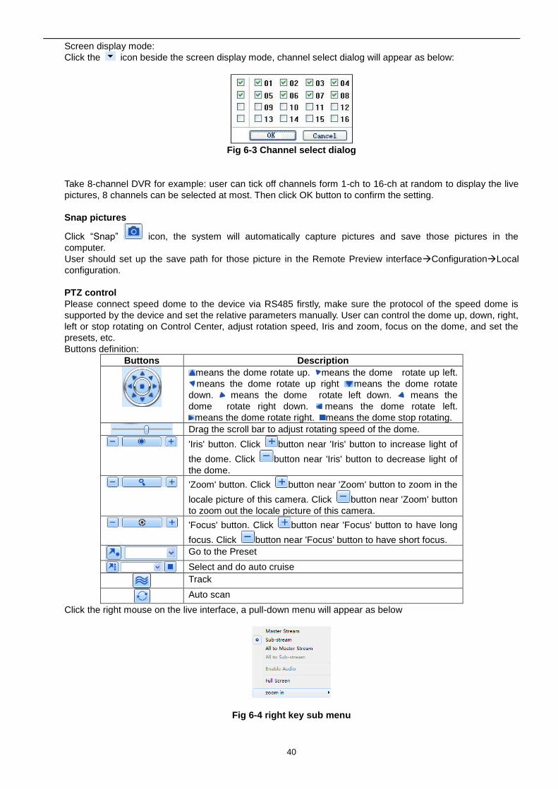
Screen display mode:
Click the icon beside the screen display mode, channel select dialog will appear as below:
Fig 6-3 Channel select dialog
Take 8-channel DVR for example: user can tick off channels form 1-ch to 16-ch at random to display the live
pictures, 8 channels can be selected at most. Then click OK button to confirm the setting.
Snap pictures
Click “Snap” icon, the system will automatically capture pictures and save those pictures in the
computer.
User should set up the save path for those picture in the Remote Preview interfaceConfigurationLocal
configuration.
PTZ control
Please connect speed dome to the device via RS485 firstly, make sure the protocol of the speed dome is
supported by the device and set the relative parameters manually. User can control the dome up, down, right,
left or stop rotating on Control Center, adjust rotation speed, Iris and zoom, focus on the dome, and set the
presets, etc.
Buttons definition:
Buttons Description
means the dome rotate up. means the dome rotate up left.
means the dome rotate up right means the dome rotate
down. means the dome rotate left down. means the
dome rotate right down. means the dome rotate left.
means the dome rotate right. means the dome stop rotating.
Drag the scroll bar to adjust rotating speed of the dome.
'Iris' button. Click button near 'Iris' button to increase light of
the dome. Click button near 'Iris' button to decrease light of
the dome.
'Zoom' button. Click button near 'Zoom' button to zoom in the
locale picture of this camera. Click button near 'Zoom' button
to zoom out the locale picture of this camera.
'Focus' button. Click button near 'Focus' button to have long
focus. Click button near 'Focus' button to have short focus.
Go to the Preset
Select and do auto cruise
Track
Auto scan
Click the right mouse on the live interface, a pull-down menu will appear as below
Fig 6-4 right key sub menu
41
Stream: this DVR supports master stream and sub stream. Master stream has higher frame rate, max 25FPS
(PAL)/30 FPS(NTSC)for every channel, but it needs higher network bandwidth simultaneously; second
stream has low frame rate, max 6FPS (PAL)/7FPS(NTSC) for every channel, it requires low network
bandwidth. Therefore, users can select the stream according to their bandwidth.
All to master/sub stream: set all channel to master stream or sub stream.
Enable audio: enable or disenable audio
Full screen: the live preview picture will display with full screen, the tool bar will be hided; double click left
mouse or click right mouse to return
Zoom in: Single channel large screen electronic amplification
Left click the channel which needs to amplify; Click the right mouse, select Zoom in button and then click the
left mouse to amplify the image. Press left mouse to drug the cursor, user can view the image. Double-click the
left mouse to exit. Click the right mouse to return to the main interface.
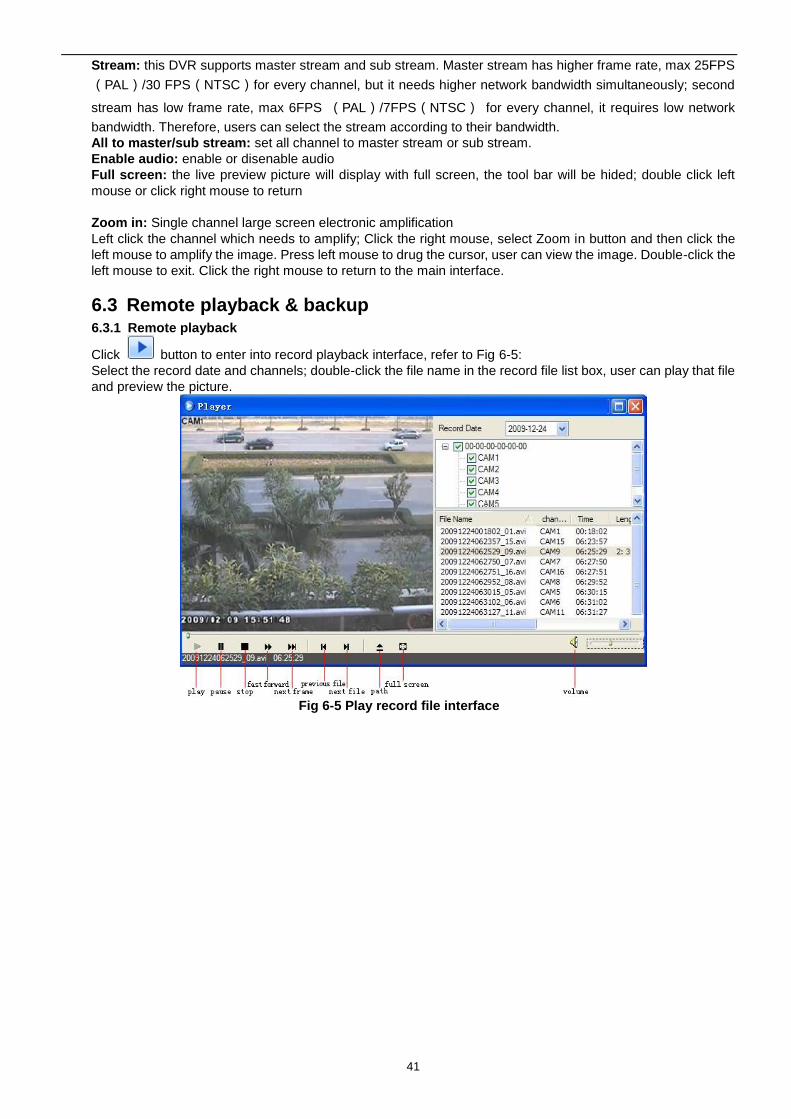
6.3 Remote playback & backup 6.3.1 Remote playback
Click button to enter into record playback interface, refer to Fig 6-5:
Select the record date and channels; double-click the file name in the record file list box, user can play that file
and preview the picture.
Fig 6-5 Play record file interface
42
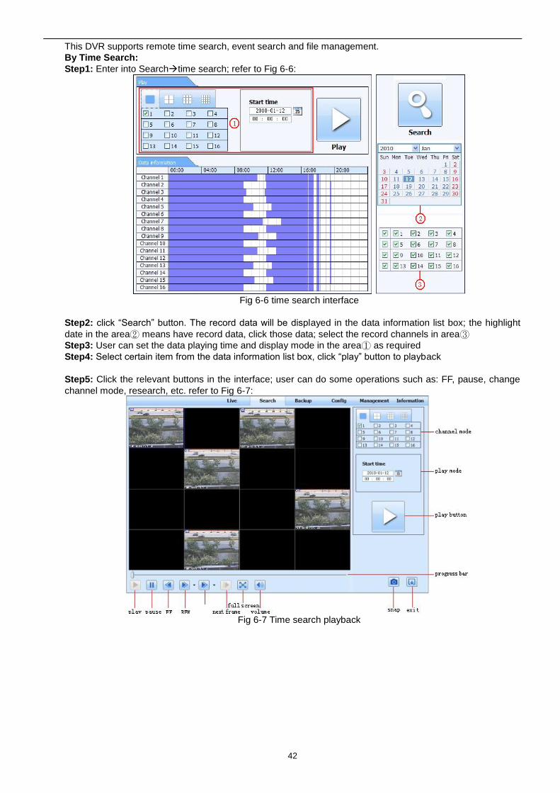
This DVR supports remote time search, event search and file management.
By Time Search:
Step1: Enter into Searchtime search; refer to Fig 6-6:
Fig 6-6 time search interface
Step2: click “Search” button. The record data will be displayed in the data information list box; the highlight
date in the area② means have record data, click those data; select the record channels in area③
Step3: User can set the data playing time and display mode in the area① as required
Step4: Select certain item from the data information list box, click “play” button to playback
Step5: Click the relevant buttons in the interface; user can do some operations such as: FF, pause, change
channel mode, research, etc. refer to Fig 6-7:
Fig 6-7 Time search playback
43
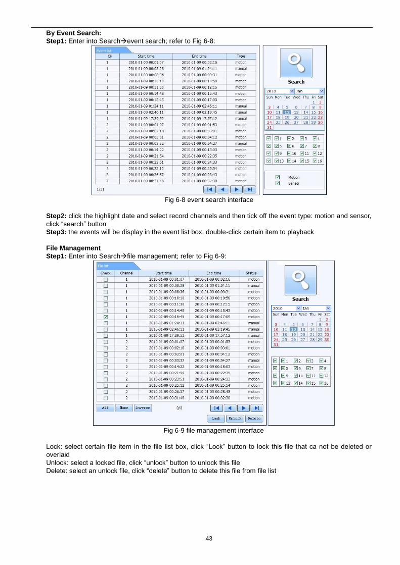
By Event Search:
Step1: Enter into Searchevent search; refer to Fig 6-8:
Fig 6-8 event search interface
Step2: click the highlight date and select record channels and then tick off the event type: motion and sensor,
click “search” button
Step3: the events will be display in the event list box, double-click certain item to playback
File Management
Step1: Enter into Searchfile management; refer to Fig 6-9:
Fig 6-9 file management interface
Lock: select certain file item in the file list box, click “Lock” button to lock this file that ca not be deleted or
overlaid
Unlock: select a locked file, click “unlock” button to unlock this file
Delete: select an unlock file, click “delete” button to delete this file from file list
44
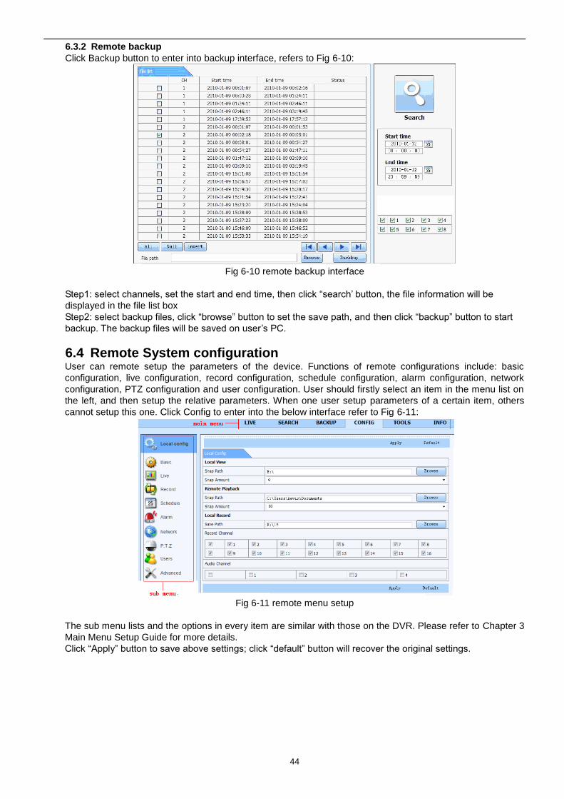
6.3.2 Remote backup
Click Backup button to enter into backup interface, refers to Fig 6-10:
Fig 6-10 remote backup interface
Step1: select channels, set the start and end time, then click “search’ button, the file information will be
displayed in the file list box
Step2: select backup files, click “browse” button to set the save path, and then click “backup” button to start
backup. The backup files will be saved on user’s PC.
6.4 Remote System configuration User can remote setup the parameters of the device. Functions of remote configurations include: basic
configuration, live configuration, record configuration, schedule configuration, alarm configuration, network
configuration, PTZ configuration and user configuration. User should firstly select an item in the menu list on
the left, and then setup the relative parameters. When one user setup parameters of a certain item, others
cannot setup this one. Click Config to enter into the below interface refer to Fig 6-11:
Fig 6-11 remote menu setup
The sub menu lists and the options in every item are similar with those on the DVR. Please refer to Chapter 3
Main Menu Setup Guide for more details.
Click “Apply” button to save above settings; click “default” button will recover the original settings.
45
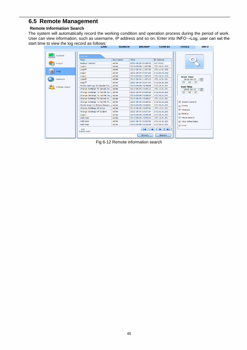
6.5 Remote Management Remote Information Search
The system will automatically record the working condition and operation process during the period of work.
User can view information, such as username, IP address and so on. Enter into INFO→Log, user can set the
start time to view the log record as follows:
Fig 6-12 Remote information search
46
7 Mobile Surveillance
This DVR supports mobile surveillance on Iphone and android OS device, this section describes the
installation of the program via the Smartphone
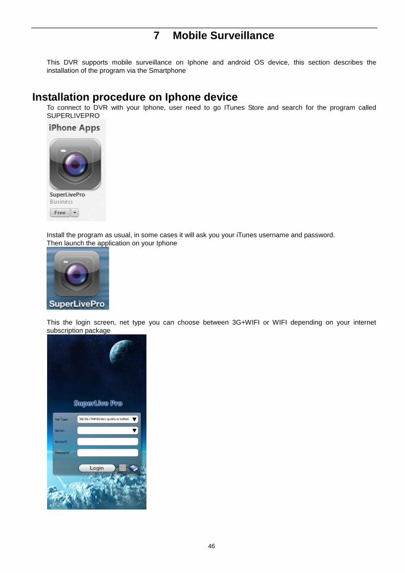
Installation procedure on Iphone device To connect to DVR with your Iphone, user need to go ITunes Store and search for the program called
SUPERLIVEPRO
Install the program as usual, in some cases it will ask you your iTunes username and password.
Then launch the application on your Iphone
This the login screen, net type you can choose between 3G+WIFI or WIFI depending on your internet
subscription package
47
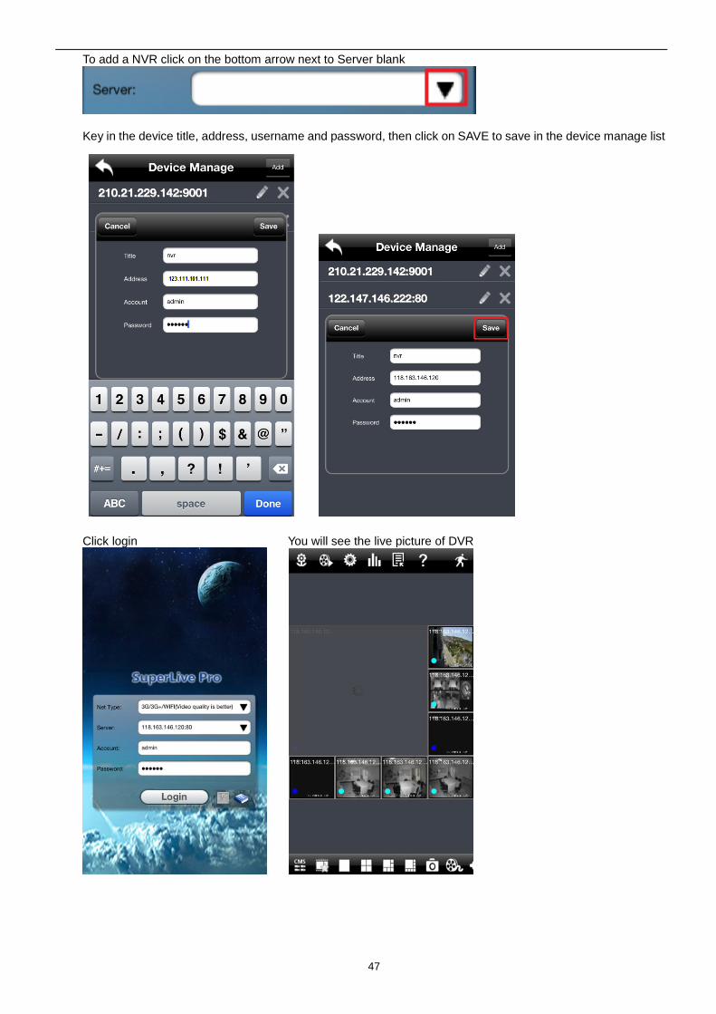
To add a NVR click on the bottom arrow next to Server blank
Key in the device title, address, username and password, then click on SAVE to save in the device manage list
Click login You will see the live picture of DVR
48
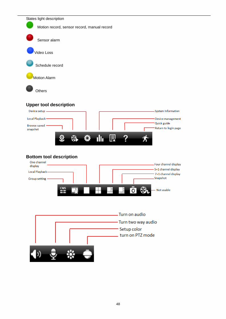
States light description
Motion record, sensor record, manual record
Sensor alarm
Video Loss
Schedule record
Motion Alarm
Others
Upper tool description
Bottom tool description
49
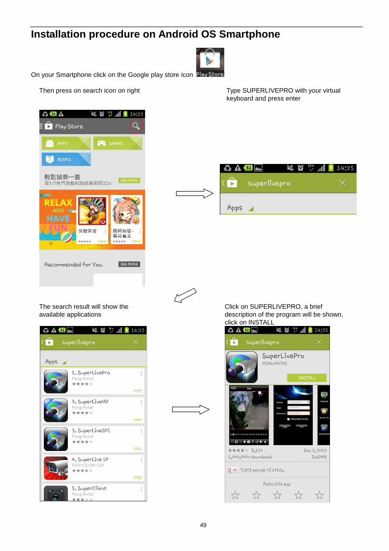
Installation procedure on Android OS Smartphone
On your Smartphone click on the Google play store icon
Then press on search icon on right Type SUPERLIVEPRO with your virtual
keyboard and press enter
The search result will show the
available applications
Click on SUPERLIVEPRO, a brief
description of the program will be shown,
click on INSTALL
50
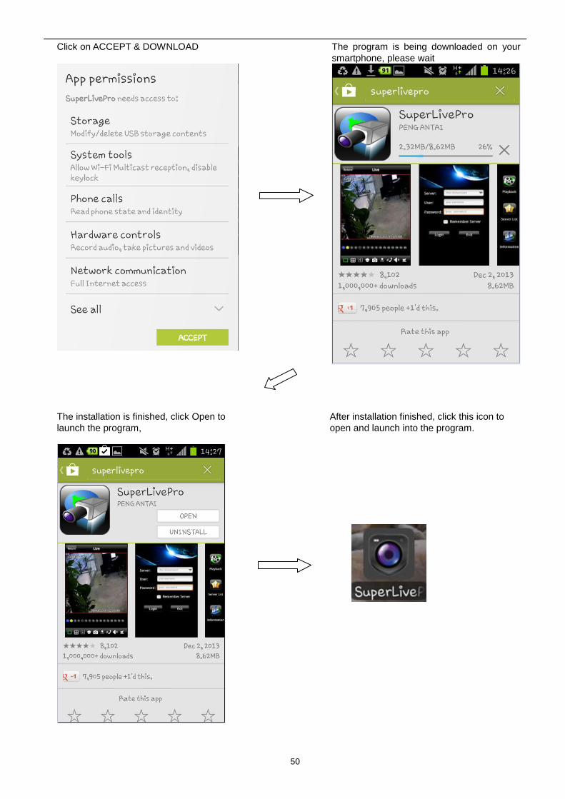
Click on ACCEPT & DOWNLOAD The program is being downloaded on your
smartphone, please wait
The installation is finished, click Open to
launch the program,
After installation finished, click this icon to
open and launch into the program.
51
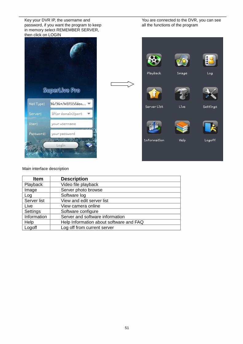
Key your DVR IP, the username and
password, if you want the program to keep
in memory select REMEMBER SERVER,
then click on LOGIN
You are connected to the DVR, you can see
all the functions of the program
Main interface description
Item Description Playback Video file playback
Image Server photo browse
Log Software log
Server list View and edit server list
Live View camera online
Settings Software configure
Information Server and software information
Help Help Information about software and FAQ
Logoff Log off from current server
52
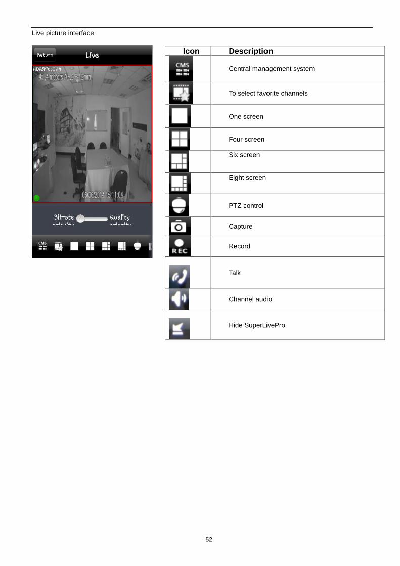
Live picture interface
Icon Description
Central management system
To select favorite channels
One screen
Four screen
Six screen
Eight screen
PTZ control
Capture
Record
Talk
Channel audio
Hide SuperLivePro
53
FAQ Q1. Why the DVR cannot start after connected to the power?
a. The adapter has been damaged. Please change an adapter
b. The power of the adapter is not enough. Please remove the HDD to check
c. Hardware problem
Q2. There is not menu output or only has live image display
a. Check up whether other devices can display menu or long press ESC key to wait for login dialog box to
appear.
Q2. The indicator of the DVR lights, but no output. Why?
a. The power of the adapter is not enough. Please remove the HDD or change an adapter to try.
b. The video format of the DVR is different from that of the monitor.
c. Connection problem. Please check the cable and the ports of monitor and DVR.
Q3. Why are no images displayed on parts or all of the channels of the DVR?
a. Connection problem. Please check the cable and the ports of camera and DVR.
b. Camera problem. Please check the cameras.
c. The video format of the DVR is different from that of the cameras. Please change DVR system format.
Q4. Cannot find HDD
a. The power of the adapter is not enough. Please change an adapter to try.
b. Connection problem. Please check the power and data cables.
c. The HDD is damaged. Change a new one.
Q5. Cannot record
a. Don't format HDD. Please format it manually first.
b. Don't enable record function or incorrect setup. Please refer to Chapter 5 Record search & playback and
backup.
c. HDD is full and not enables recycle function. Please refer to 4.3 Record configuration. Chang a new HDD or
enable recycle.
d. The HDD is damaged. Change a new one.
Q6. Cannot use mouse.
a. wait 1-2 minutes after mouse connected.
b. Not detected. Plug/unplug several times.
c. The mouse is incompatible. Please change a mouse.
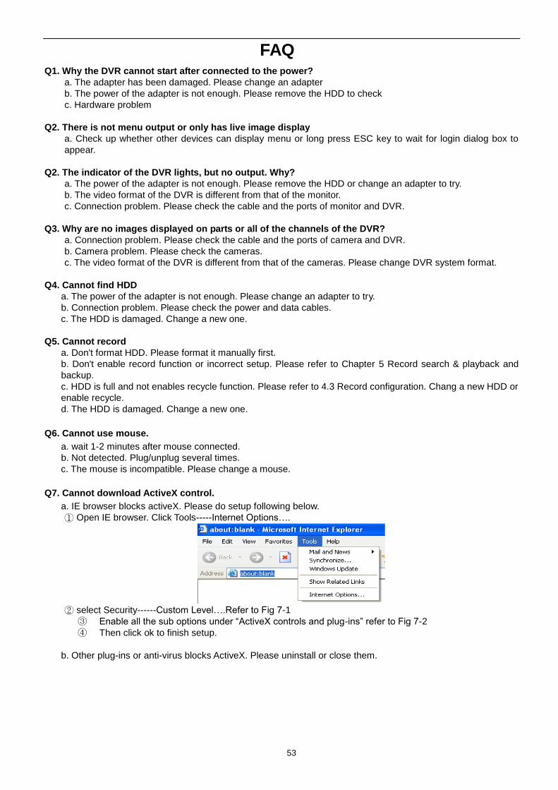
Q7. Cannot download ActiveX control.
a. IE browser blocks activeX. Please do setup following below.
① Open IE browser. Click Tools-----Internet Options….
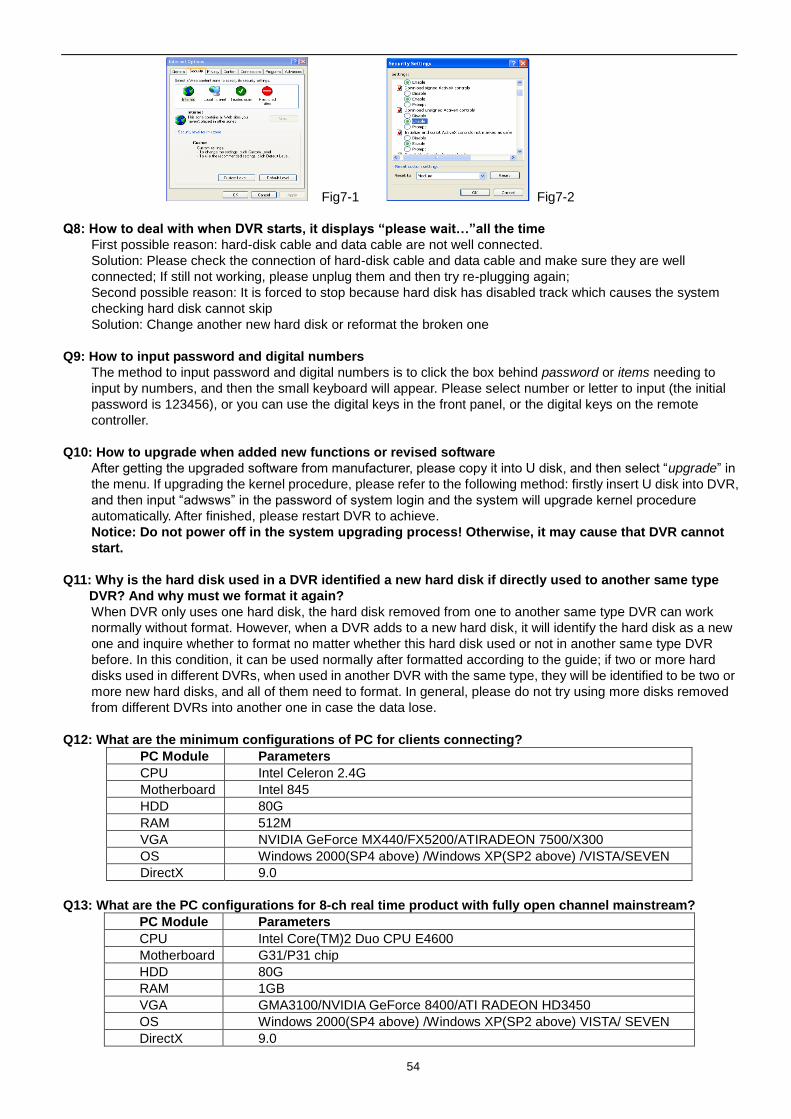
② select Security------Custom Level….Refer to Fig 7-1
③ Enable all the sub options under “ActiveX controls and plug-ins” refer to Fig 7-2
④ Then click ok to finish setup.
b. Other plug-ins or anti-virus blocks ActiveX. Please uninstall or close them.
54
Fig7-1 Fig7-2
Q8: How to deal with when DVR starts, it displays “please wait…”all the time
First possible reason: hard-disk cable and data cable are not well connected.
Solution: Please check the connection of hard-disk cable and data cable and make sure they are well
connected; If still not working, please unplug them and then try re-plugging again;
Second possible reason: It is forced to stop because hard disk has disabled track which causes the system
checking hard disk cannot skip
Solution: Change another new hard disk or reformat the broken one
Q9: How to input password and digital numbers
The method to input password and digital numbers is to click the box behind password or items needing to
input by numbers, and then the small keyboard will appear. Please select number or letter to input (the initial
password is 123456), or you can use the digital keys in the front panel, or the digital keys on the remote
controller.
Q10: How to upgrade when added new functions or revised software
After getting the upgraded software from manufacturer, please copy it into U disk, and then select “upgrade” in
the menu. If upgrading the kernel procedure, please refer to the following method: firstly insert U disk into DVR,
and then input “adwsws” in the password of system login and the system will upgrade kernel procedure
automatically. After finished, please restart DVR to achieve.
Notice: Do not power off in the system upgrading process! Otherwise, it may cause that DVR cannot
start.
Q11: Why is the hard disk used in a DVR identified a new hard disk if directly used to another same type
DVR? And why must we format it again?
When DVR only uses one hard disk, the hard disk removed from one to another same type DVR can work
normally without format. However, when a DVR adds to a new hard disk, it will identify the hard disk as a new
one and inquire whether to format no matter whether this hard disk used or not in another same type DVR
before. In this condition, it can be used normally after formatted according to the guide; if two or more hard
disks used in different DVRs, when used in another DVR with the same type, they will be identified to be two or
more new hard disks, and all of them need to format. In general, please do not try using more disks removed
from different DVRs into another one in case the data lose.
Q12: What are the minimum configurations of PC for clients connecting?
PC Module Parameters
CPU Intel Celeron 2.4G
Motherboard Intel 845
HDD 80G
RAM 512M
VGA NVIDIA GeForce MX440/FX5200/ATIRADEON 7500/X300
OS Windows 2000(SP4 above) /Windows XP(SP2 above) /VISTA/SEVEN
DirectX 9.0
Q13: What are the PC configurations for 8-ch real time product with fully open channel mainstream?
PC Module Parameters
CPU Intel Core(TM)2 Duo CPU E4600
Motherboard G31/P31 chip
HDD 80G
RAM 1GB
VGA GMA3100/NVIDIA GeForce 8400/ATI RADEON HD3450
OS Windows 2000(SP4 above) /Windows XP(SP2 above) VISTA/ SEVEN
DirectX 9.0
55
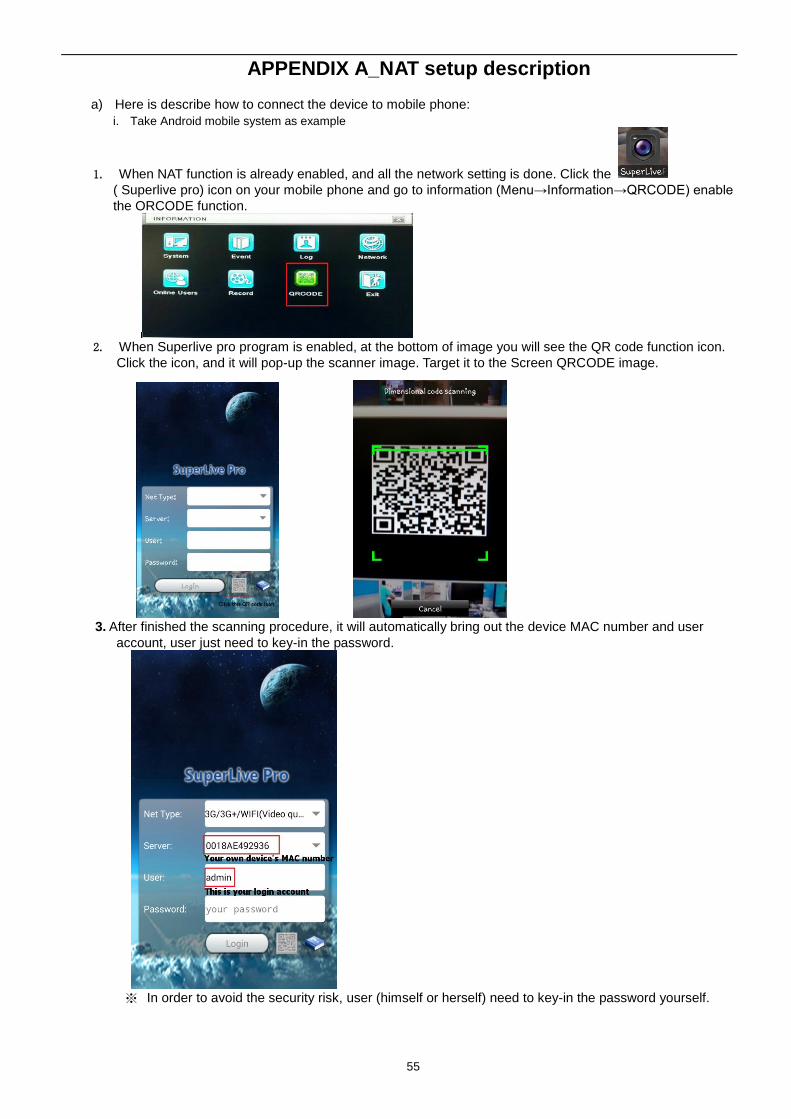
APPENDIX A_NAT setup description
a) Here is describe how to connect the device to mobile phone:
i. Take Android mobile system as example
1. When NAT function is already enabled, and all the network setting is done. Click the
( Superlive pro) icon on your mobile phone and go to information (Menu→Information→QRCODE) enable
the ORCODE function.
2. When Superlive pro program is enabled, at the bottom of image you will see the QR code function icon.
Click the icon, and it will pop-up the scanner image. Target it to the Screen QRCODE image.
3. After finished the scanning procedure, it will automatically bring out the device MAC number and user
account, user just need to key-in the password.
※ In order to avoid the security risk, user (himself or herself) need to key-in the password yourself.
56
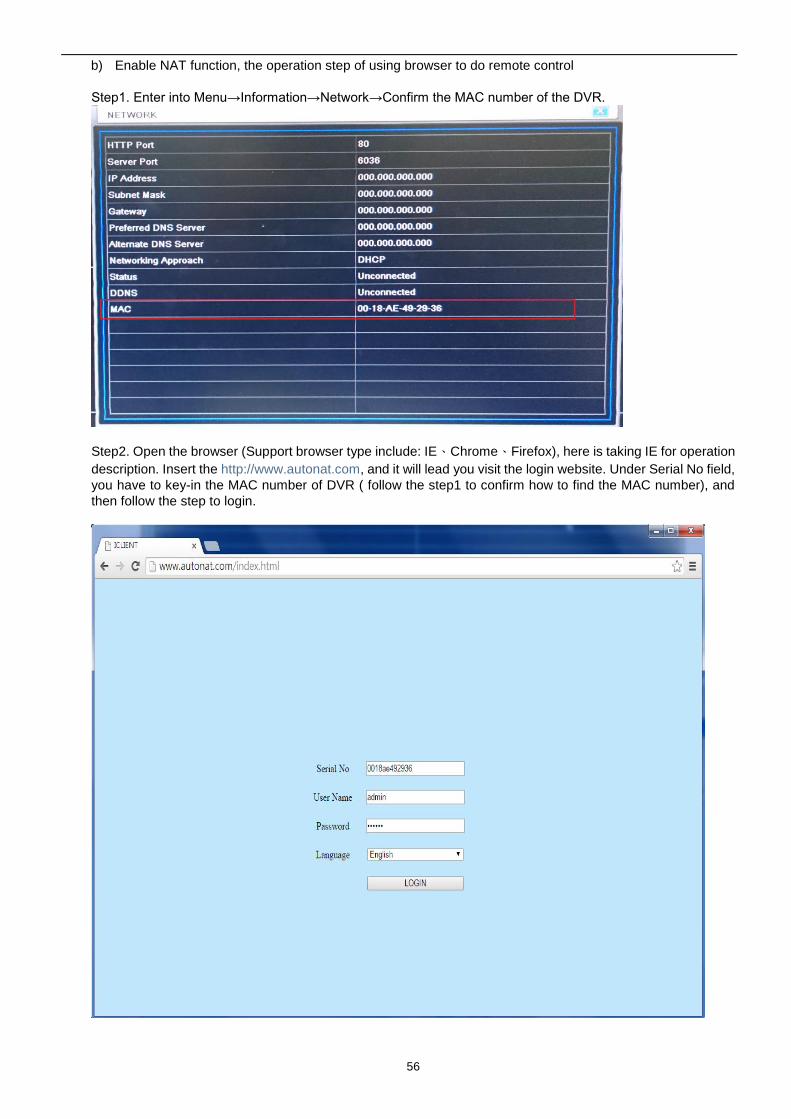
b) Enable NAT function, the operation step of using browser to do remote control
Step1. Enter into Menu→Information→Network→Confirm the MAC number of the DVR.
Step2. Open the browser (Support browser type include: IE、Chrome、Firefox), here is taking IE for operation
description. Insert the http://www.autonat.com, and it will lead you visit the login website. Under Serial No field,
you have to key-in the MAC number of DVR ( follow the step1 to confirm how to find the MAC number), and
then follow the step to login.
57
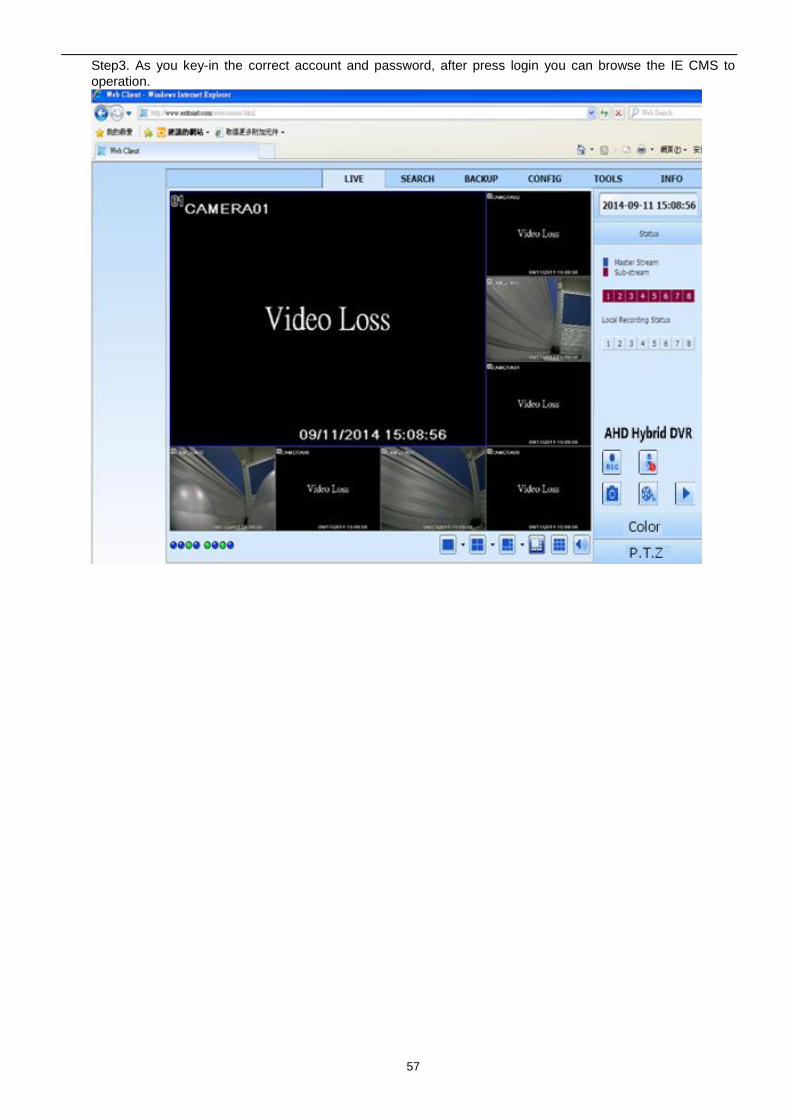
Step3. As you key-in the correct account and password, after press login you can browse the IE CMS to
operation.
58
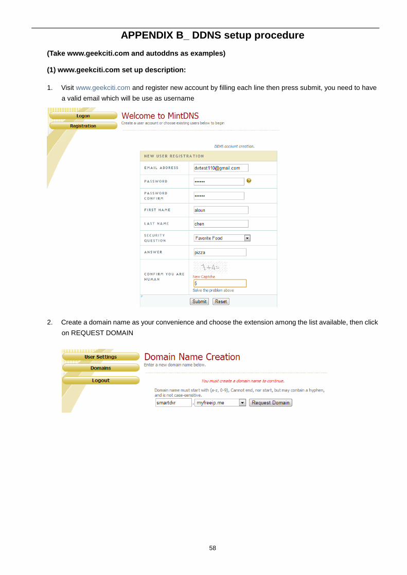
APPENDIX B_ DDNS setup procedure
(Take www.geekciti.com and autoddns as examples)
(1) www.geekciti.com set up description:
1. Visit www.geekciti.com and register new account by filling each line then press submit, you need to have
a valid email which will be use as username
2. Create a domain name as your convenience and choose the extension among the list available, then click
on REQUEST DOMAIN
59
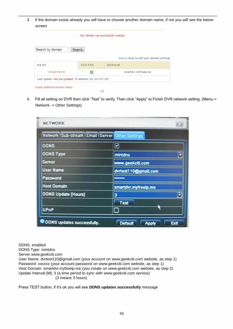
3. If the domain exists already you will have to choose another domain name, if not you will see the below
screen
4. Fill all setting on DVR then click “Test” to verify. Then click “Apply” to Finish DVR network setting. (Menu->
Network -> Other Settings)
DDNS: enabled
DDNS Type: mintdns
Server www.geekciti.com
User Name: [email protected] (your account on www.geekciti.com website, as step 1)
Password: xxxxxx (your account password on www.geekciti.com website, as step 1)
Host Domain: smartdvr.myfreeip.me (you create on www.geekciti.com website, as step 2)
Update Interval [M]: 3 (a time period to sync with www.geekciti.com service)
(3 means 3 hours)
Press TEST button, if it’s ok you will see DDNS updates successfully message
60
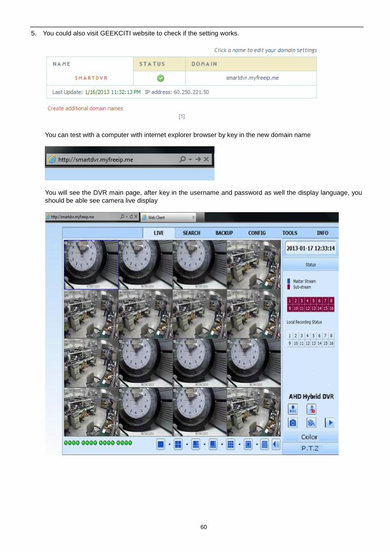
5. You could also visit GEEKCITI website to check if the setting works.
You can test with a computer with internet explorer browser by key in the new domain name
You will see the DVR main page, after key in the username and password as well the display language, you
should be able see camera live display
61
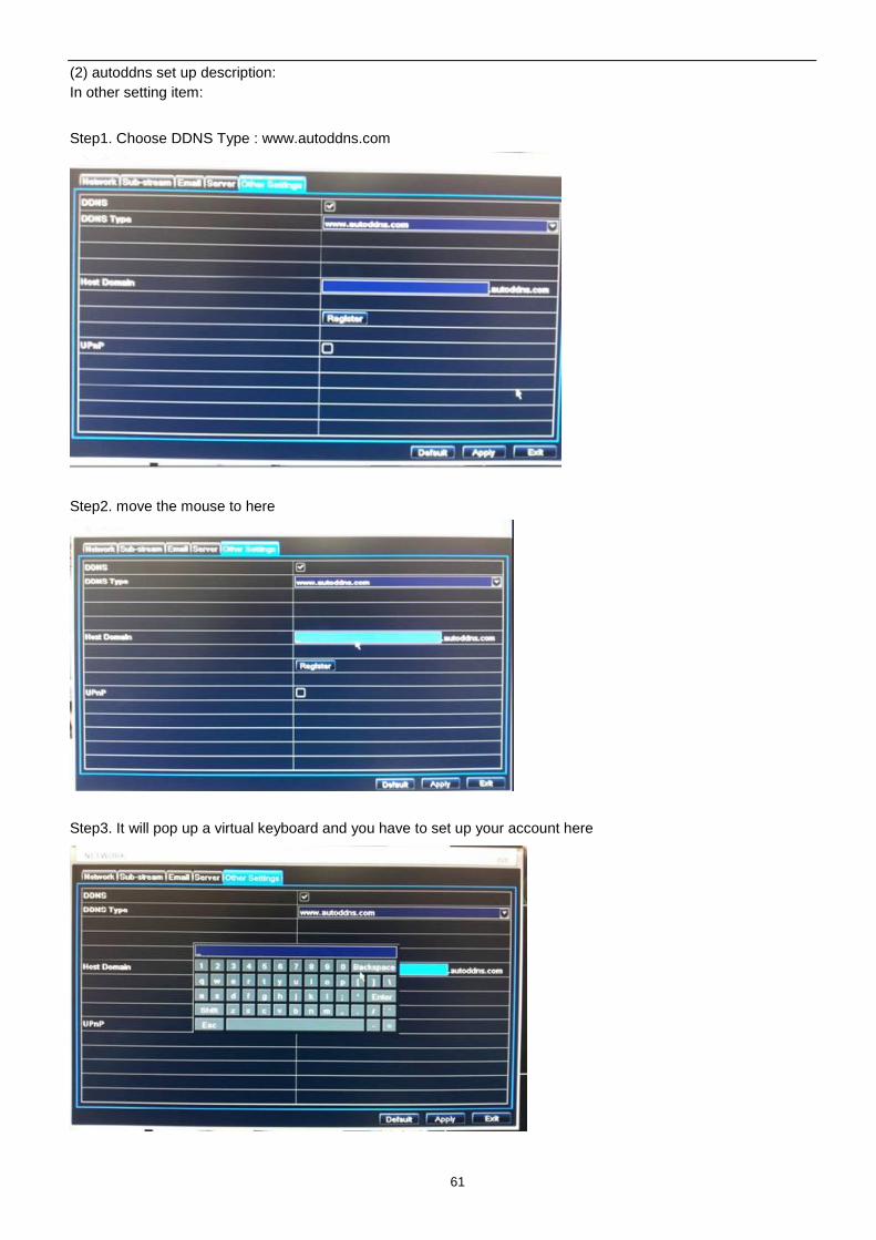
(2) autoddns set up description:
In other setting item:
Step1. Choose DDNS Type : www.autoddns.com
Step2. move the mouse to here
Step3. It will pop up a virtual keyboard and you have to set up your account here
62
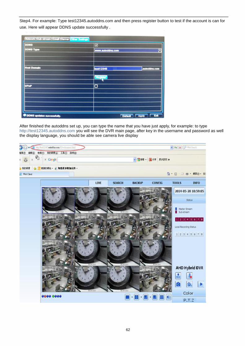
Step4. For example: Type test12345.autoddns.com and then press register button to test if the account is can for
use. Here will appear DDNS update successfully .
After finished the autoddns set up, you can type the name that you have just apply, for example: to type http://test12345.autoddns.com you will see the DVR main page, after key in the username and password as well the display language, you should be able see camera live display
63
APPENDIX C_Calculate Recording Capacity
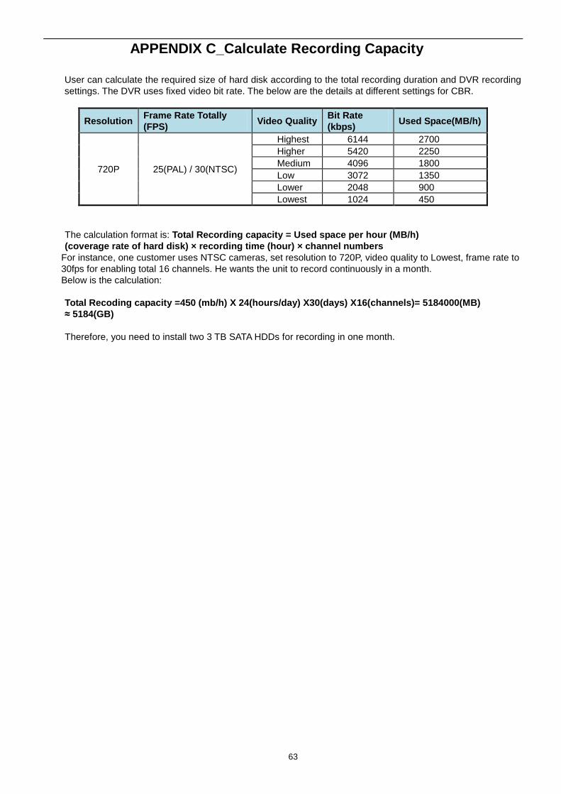
User can calculate the required size of hard disk according to the total recording duration and DVR recording
settings. The DVR uses fixed video bit rate. The below are the details at different settings for CBR.
Resolution Frame Rate Totally
(FPS) Video Quality
Bit Rate
(kbps) Used Space(MB/h)
720P 25(PAL) / 30(NTSC)
Highest 6144 2700
Higher 5420 2250
Medium 4096 1800
Low 3072 1350
Lower 2048 900
Lowest 1024 450
The calculation format is: Total Recording capacity = Used space per hour (MB/h)
(coverage rate of hard disk) × recording time (hour) × channel numbers
For instance, one customer uses NTSC cameras, set resolution to 720P, video quality to Lowest, frame rate to
30fps for enabling total 16 channels. He wants the unit to record continuously in a month.
Below is the calculation:
Total Recoding capacity =450 (mb/h) X 24(hours/day) X30(days) X16(channels)= 5184000(MB)
≈ 5184(GB)
Therefore, you need to install two 3 TB SATA HDDs for recording in one month.
64
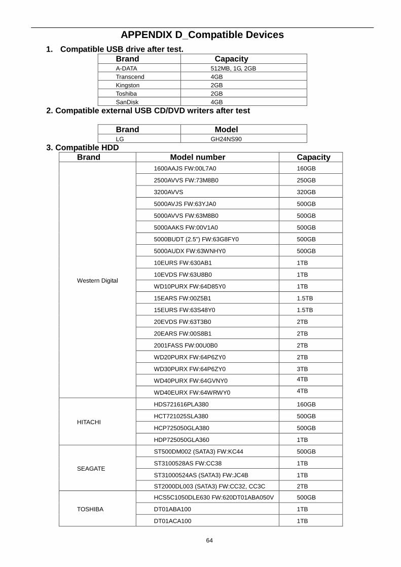
APPENDIX D_Compatible Devices
1. Compatible USB drive after test.
Brand Capacity A-DATA 512MB, 1G, 2GB
Transcend 4GB
Kingston 2GB
Toshiba 2GB
SanDisk 4GB
2. Compatible external USB CD/DVD writers after test
Brand Model LG GH24NS90
3. Compatible HDD
Brand Model number Capacity
Western Digital
1600AAJS FW:00L7A0 160GB
2500AVVS FW:73M8B0 250GB
3200AVVS 320GB
5000AVJS FW:63YJA0 500GB
5000AVVS FW:63M8B0 500GB
5000AAKS FW:00V1A0 500GB
5000BUDT (2.5") FW:63G8FY0 500GB
5000AUDX FW:63WNHY0 500GB
10EURS FW:630AB1 1TB
10EVDS FW:63U8B0 1TB
WD10PURX FW:64D85Y0 1TB
15EARS FW:00Z5B1 1.5TB
15EURS FW:63S48Y0 1.5TB
20EVDS FW:63T3B0 2TB
20EARS FW:00S8B1 2TB
2001FASS FW:00U0B0 2TB
WD20PURX FW:64P6ZY0 2TB
WD30PURX FW:64P6ZY0 3TB
WD40PURX FW:64GVNY0 4TB
WD40EURX FW:64WRWY0 4TB
HITACHI
HDS721616PLA380 160GB
HCT721025SLA380 500GB
HCP725050GLA380 500GB
HDP725050GLA360 1TB
SEAGATE
ST500DM002 (SATA3) FW:KC44 500GB
ST3100528AS FW:CC38 1TB
ST31000524AS (SATA3) FW:JC4B 1TB
ST2000DL003 (SATA3) FW:CC32, CC3C 2TB
TOSHIBA
HCS5C1050DLE630 FW:620DT01ABA050V 500GB
DT01ABA100 1TB
DT01ACA100 1TB
65
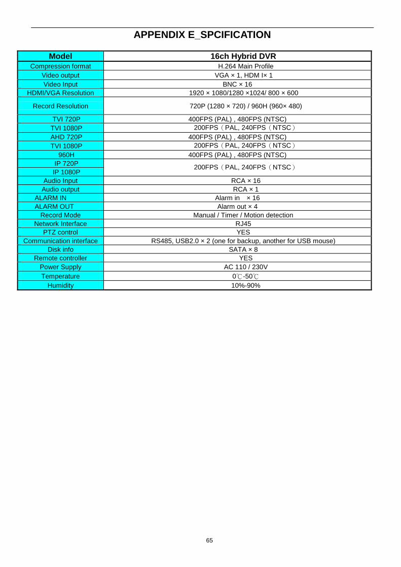
APPENDIX E_SPCIFICATION
Model 16ch Hybrid DVR
Compression format H.264 Main Profile
Video output VGA × 1, HDM I× 1
Video Input BNC × 16
HDMI/VGA Resolution 1920 × 1080/1280 ×1024/ 800 × 600
Record Resolution 720P (1280 × 720) / 960H (960× 480)
TVI 720P 400FPS (PAL) , 480FPS (NTSC)
TVI 1080P 200FPS(PAL, 240FPS(NTSC)
AHD 720P 400FPS (PAL) , 480FPS (NTSC)
TVI 1080P 200FPS(PAL, 240FPS(NTSC)
960H 400FPS (PAL) , 480FPS (NTSC)
IP 720P 200FPS(PAL, 240FPS(NTSC)
IP 1080P
Audio Input RCA × 16
Audio output RCA × 1
ALARM IN Alarm in × 16
ALARM OUT Alarm out × 4
Record Mode Manual / Timer / Motion detection
Network Interface RJ45
PTZ control YES
Communication interface RS485, USB2.0 × 2 (one for backup, another for USB mouse)
Disk info SATA × 8
Remote controller YES
Power Supply AC 110 / 230V
Temperature 0℃-50℃
Humidity 10%-90%