Embed Size (px)
Citation preview
DVMS Training
Rev 1.1
Due to Samsung’s policy of ongoing product development, specifications are subject to change without prior notice.
Every effort has been made to insure that the information included in this presentation is as accurate as possible at the
time of it’s publication.
This training module is provided to help HVAC field technicians understand the most basic installation procedures for
the Samsung DVM S systems. This presentation is not intended to replace Samsung Installation/Operation manuals or
other factory documents.
Only properly trained, professional HVAC field technicians should attempt to install and start up any Samsung heating
and air-conditioning system.
High Voltage Caution:
Extra care must be taken when working on or around DVMS equipment due to numerous high voltage components.
Whether installing or servicing DVMS equipment in the field or while attending Samsung HVAC training classes which
include powered simulators and equipment, be aware of the potential dangers of high voltage – use caution
This presentation may only be used with authorization by Samsung HVAC. Unauthorized use, duplication or alteration
of this presentation is prohibited.
For technical support issues, always contact your Samsung equipment provider.
www.samsunghvac.com https://samsunghvac.learnernation.com www.dvmdownload.com
2
DVM S Training
3
DVM S Training
Training Topics
▪ DVMS Refrigerant Piping Introduction
▪ Field Piping Components
▪ Piping Installation Tools
▪ Field Piping Installation
▪ Additional Guidelines

DVM S
Refrigerant Piping Introduction
5
Refrigerant Piping Introduction
▪ Samsung piping installation guidelines and restrictions
must be strictly adhered to
▪ Failure to follow Samsung piping guidelines may result
in poor system performance, premature component
failure, and reduced system service life
▪ Always refer to the DVM Pro piping diagram and
mechanical prints when laying out the refrigerant piping
system
6
Refrigerant Piping Introduction
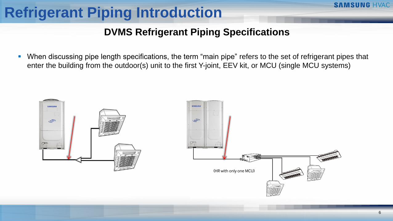
DVMS Refrigerant Piping Specifications
▪ When discussing pipe length specifications, the term “main pipe” refers to the set of refrigerant pipes that
enter the building from the outdoor(s) unit to the first Y-joint, EEV kit, or MCU (single MCU systems)
(HR with only one MCU)
7
Refrigerant Piping Introduction
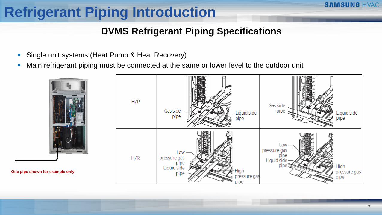
DVMS Refrigerant Piping Specifications
▪ Single unit systems (Heat Pump & Heat Recovery)
▪ Main refrigerant piping must be connected at the same or lower level to the outdoor unit
One pipe shown for example only
8
Refrigerant Piping Introduction
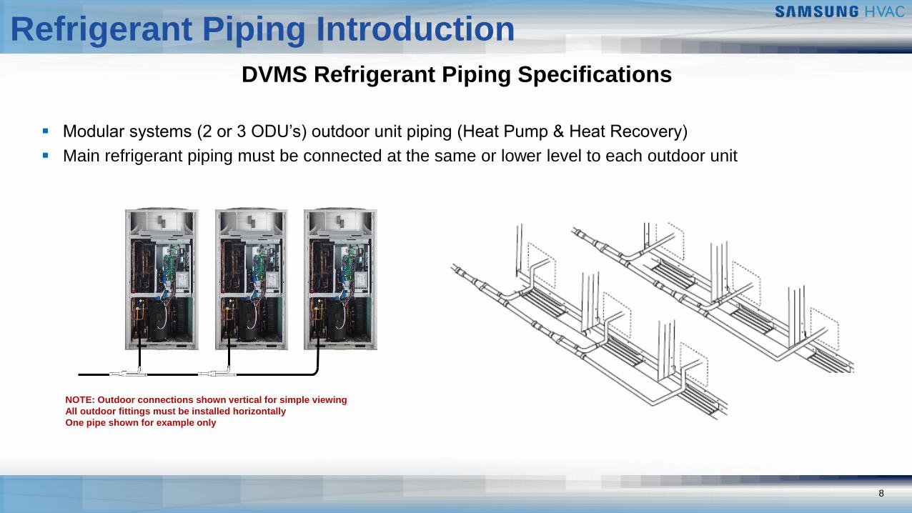
DVMS Refrigerant Piping Specifications
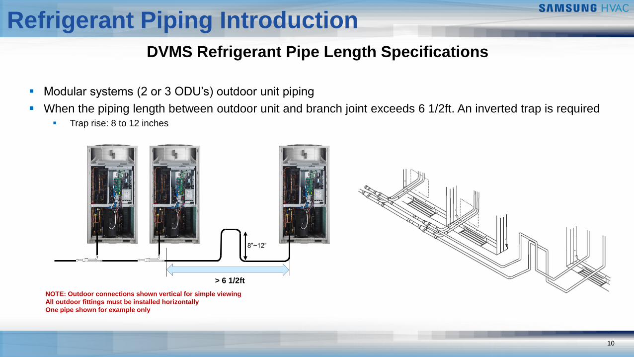
▪ Modular systems (2 or 3 ODU’s) outdoor unit piping (Heat Pump & Heat Recovery)
▪ Main refrigerant piping must be connected at the same or lower level to each outdoor unit
NOTE: Outdoor connections shown vertical for simple viewing
All outdoor fittings must be installed horizontally
One pipe shown for example only
9
Refrigerant Piping Introduction
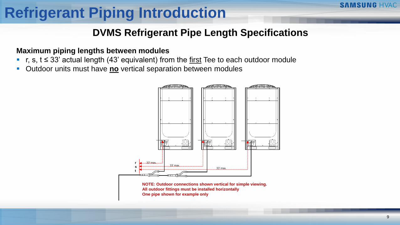
DVMS Refrigerant Pipe Length Specifications
33’ max.33’ max.
33’ max.
NOTE: Outdoor connections shown vertical for simple viewing.
All outdoor fittings must be installed horizontally
One pipe shown for example only
Maximum piping lengths between modules
▪ r, s, t ≤ 33’ actual length (43’ equivalent) from the first Tee to each outdoor module
▪ Outdoor units must have no vertical separation between modules
r
s
t
10
Refrigerant Piping Introduction
DVMS Refrigerant Pipe Length Specifications
▪ Modular systems (2 or 3 ODU’s) outdoor unit piping
▪ When the piping length between outdoor unit and branch joint exceeds 6 1/2ft. An inverted trap is required▪ Trap rise: 8 to 12 inches
> 6 1/2ft
8”~12”
NOTE: Outdoor connections shown vertical for simple viewing
All outdoor fittings must be installed horizontally
One pipe shown for example only
Refrigerant Piping Introduction
DVMS Refrigerant Pipe Length Specifications
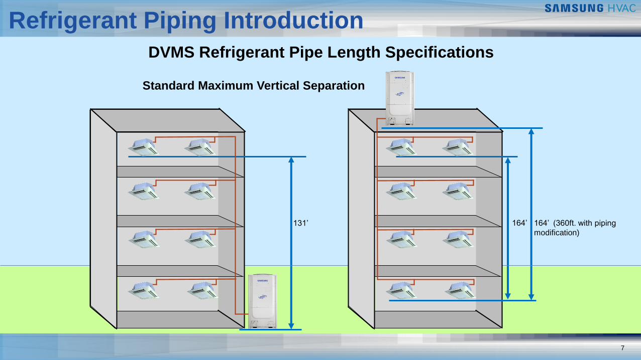
Standard Maximum Vertical Separation
131’ 164’ 164’ (360ft. with piping
modification)
7
12
Refrigerant Piping Introduction
DVMS Refrigerant Pipe Length Specifications
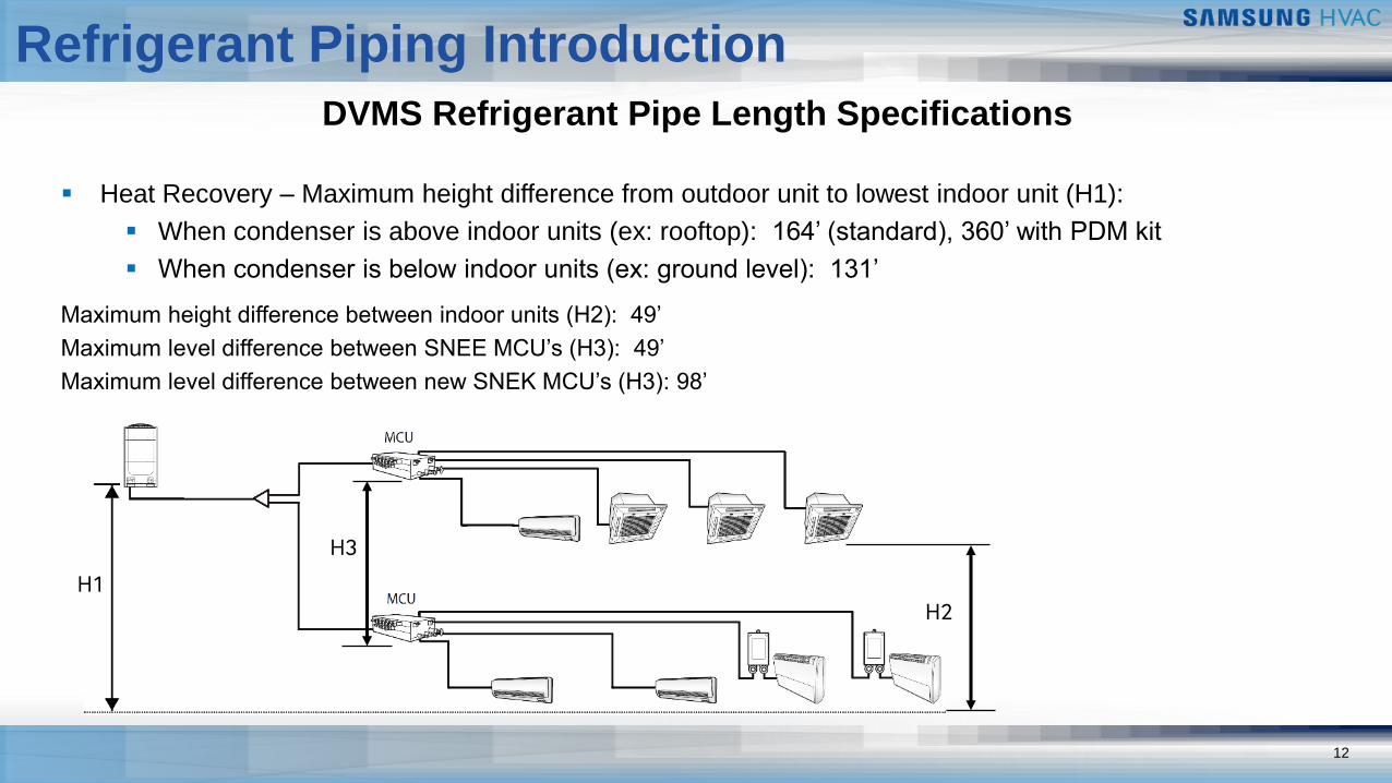
▪ Heat Recovery – Maximum height difference from outdoor unit to lowest indoor unit (H1):
▪ When condenser is above indoor units (ex: rooftop): 164’ (standard), 360’ with PDM kit
▪ When condenser is below indoor units (ex: ground level): 131’
Maximum height difference between indoor units (H2): 49’
Maximum level difference between SNEE MCU’s (H3): 49’
Maximum level difference between new SNEK MCU’s (H3): 98’
H1H2
H3
13
Refrigerant Piping Introduction
1
DVMS Refrigerant Pipe Length Specifications
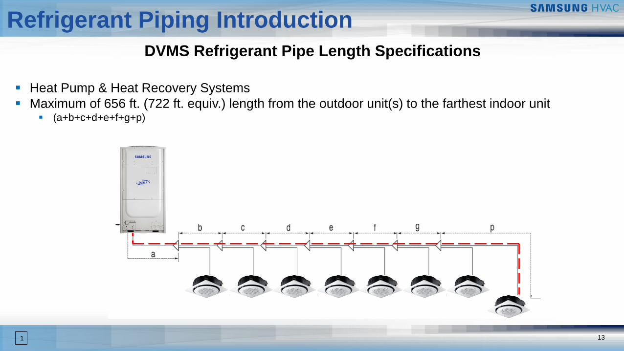
▪ Heat Pump & Heat Recovery Systems
▪ Maximum of 656 ft. (722 ft. equiv.) length from the outdoor unit(s) to the farthest indoor unit▪ (a+b+c+d+e+f+g+p)
14
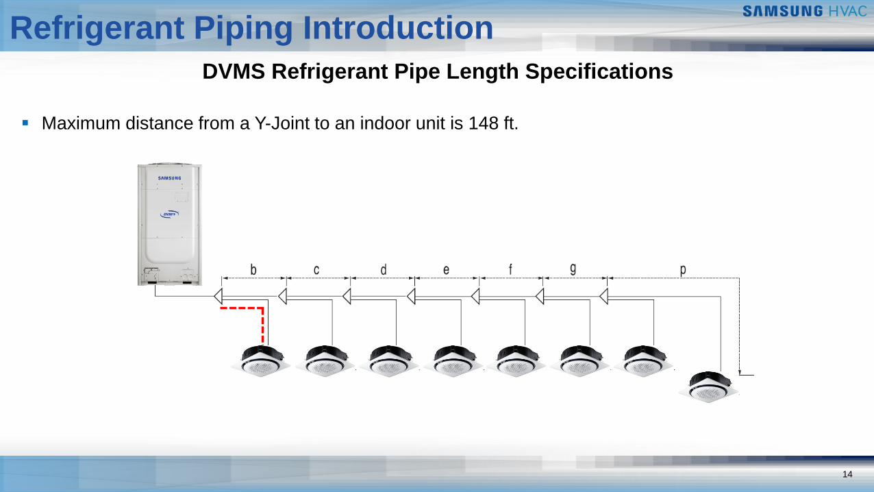
Refrigerant Piping Introduction
DVMS Refrigerant Pipe Length Specifications
▪ Maximum distance from a Y-Joint to an indoor unit is 148 ft.
15
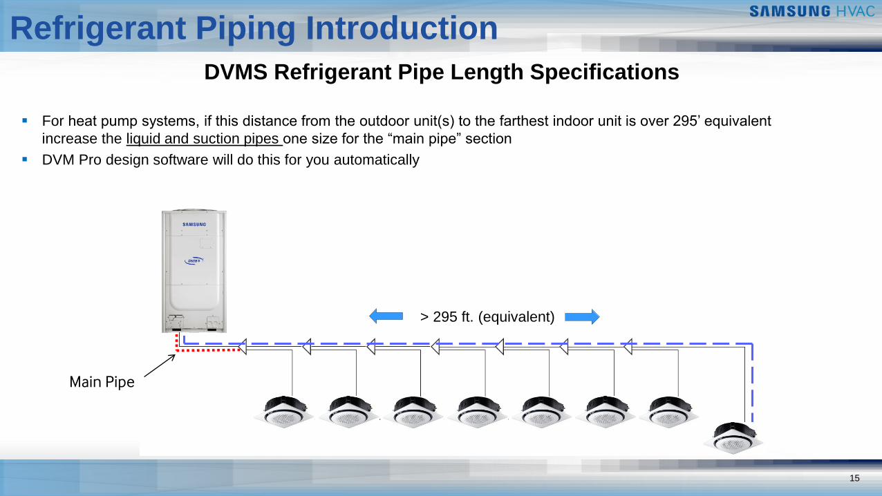
Refrigerant Piping Introduction
DVMS Refrigerant Pipe Length Specifications
▪ For heat pump systems, if this distance from the outdoor unit(s) to the farthest indoor unit is over 295’ equivalent
increase the liquid and suction pipes one size for the “main pipe” section
▪ DVM Pro design software will do this for you automatically
> 295 ft. (equivalent)
Main Pipe
16
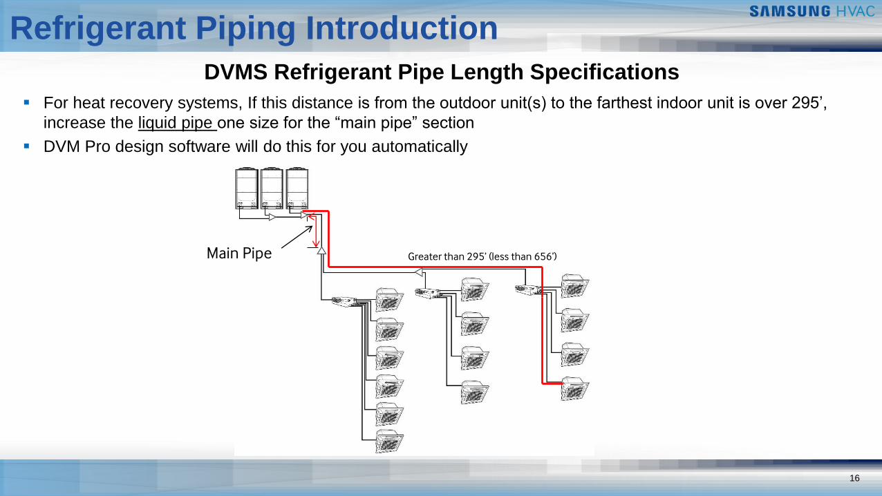
Refrigerant Piping Introduction
DVMS Refrigerant Pipe Length Specifications
▪ For heat recovery systems, If this distance is from the outdoor unit(s) to the farthest indoor unit is over 295’,
increase the liquid pipe one size for the “main pipe” section
▪ DVM Pro design software will do this for you automatically
Main Pipe Greater than 295’ (less than 656’)
17
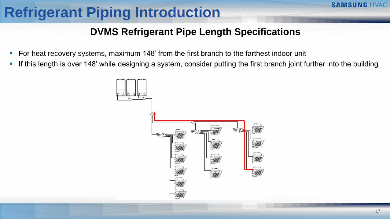
Refrigerant Piping Introduction
DVMS Refrigerant Pipe Length Specifications
▪ For heat recovery systems, maximum 148’ from the first branch to the farthest indoor unit
▪ If this length is over 148’ while designing a system, consider putting the first branch joint further into the building
18
Refrigerant Piping Introduction
DVMS Refrigerant Pipe Length Specifications
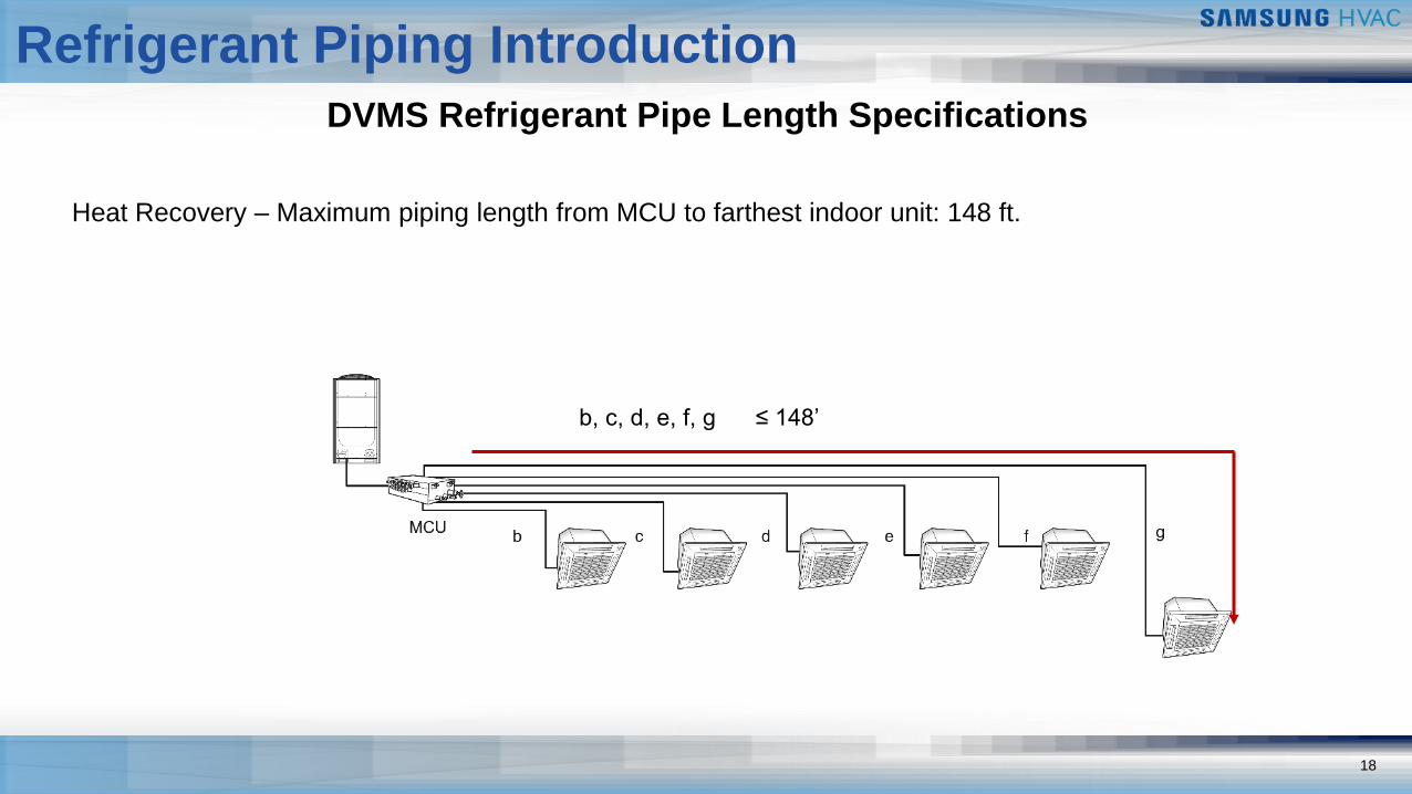
Heat Recovery – Maximum piping length from MCU to farthest indoor unit: 148 ft.
b, c, d, e, f, g ≤ 148’
19
Refrigerant Piping Introduction
DVMS Refrigerant Pipe Length Specifications
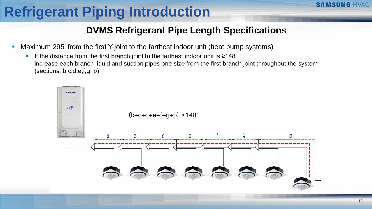
(b+c+d+e+f+g+p) ≤148’
▪ Maximum 295’ from the first Y-joint to the farthest indoor unit (heat pump systems)
▪ If the distance from the first branch joint to the farthest indoor unit is ≥148’
increase each branch liquid and suction pipes one size from the first branch joint throughout the system
(sections: b,c,d,e,f,g+p)
20
Refrigerant Piping Introduction
DVMS Refrigerant Pipe Length Specifications
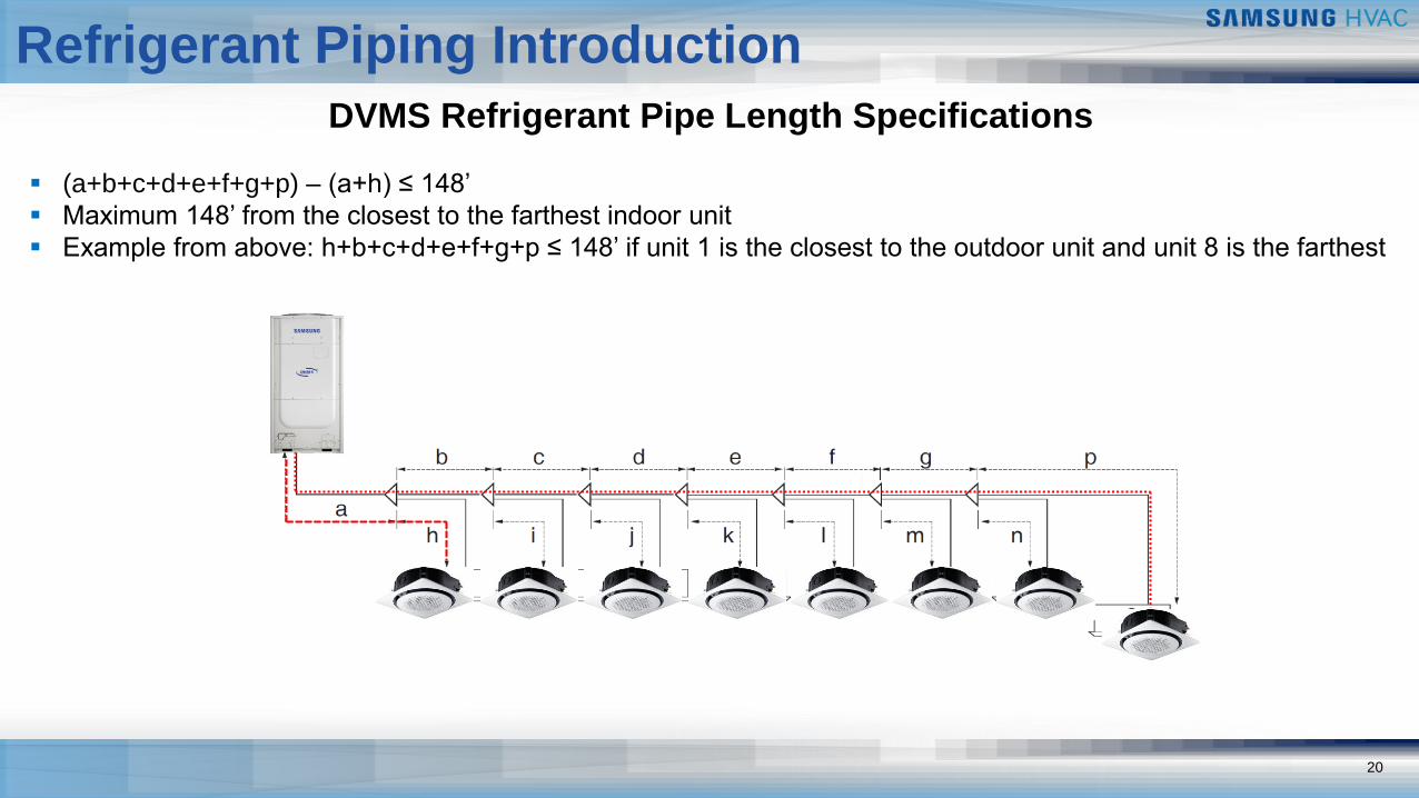
▪ (a+b+c+d+e+f+g+p) – (a+h) ≤ 148’
▪ Maximum 148’ from the closest to the farthest indoor unit
▪ Example from above: h+b+c+d+e+f+g+p ≤ 148’ if unit 1 is the closest to the outdoor unit and unit 8 is the farthest
21
Refrigerant Piping Introduction
1
DVMS Refrigerant Pipe Length Specifications
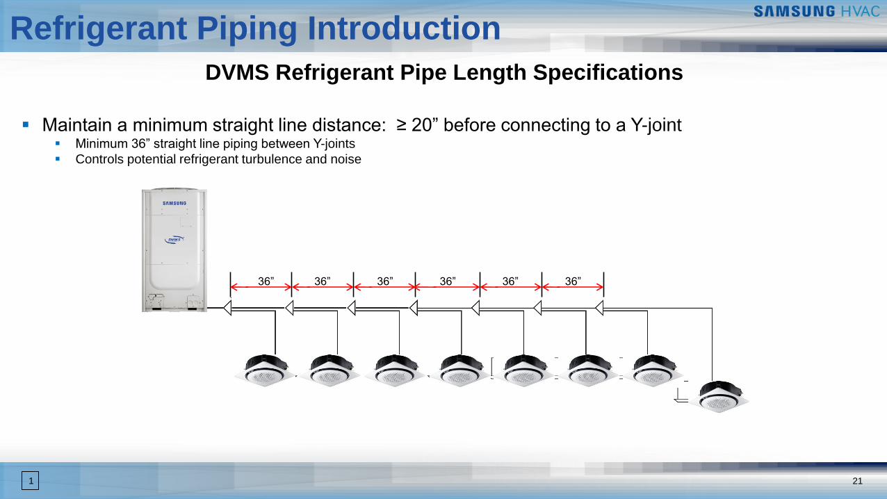
▪ Maintain a minimum straight line distance: ≥ 20” before connecting to a Y-joint▪ Minimum 36” straight line piping between Y-joints
▪ Controls potential refrigerant turbulence and noise
36” 36” 36” 36” 36” 36”
Refrigerant Piping Introduction
22
DVM Pro System Design Software
Refrigerant Piping Introduction
23
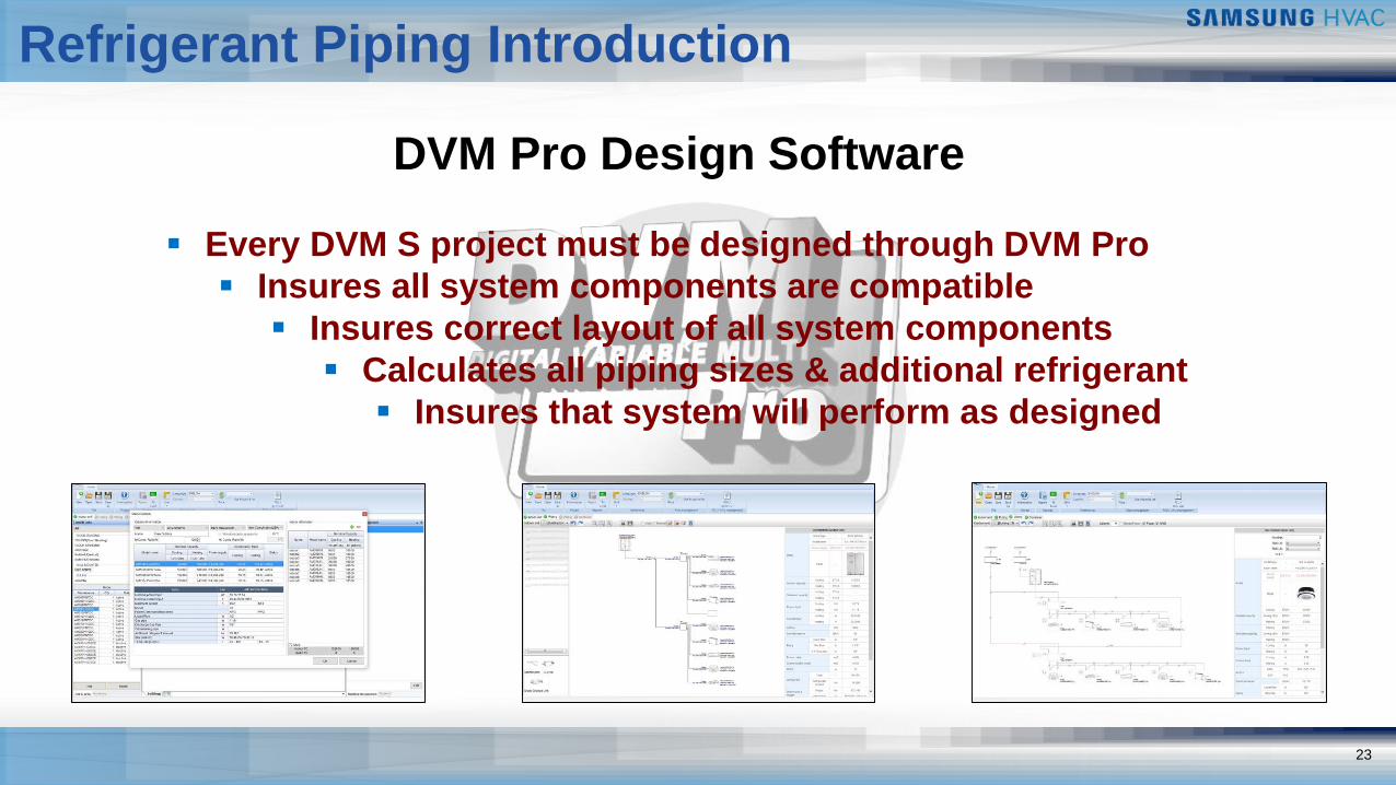
DVM Pro Design Software
▪ Every DVM S project must be designed through DVM Pro
▪ Insures all system components are compatible
▪ Insures correct layout of all system components
▪ Calculates all piping sizes & additional refrigerant
▪ Insures that system will perform as designed
Refrigerant Piping Introduction
24
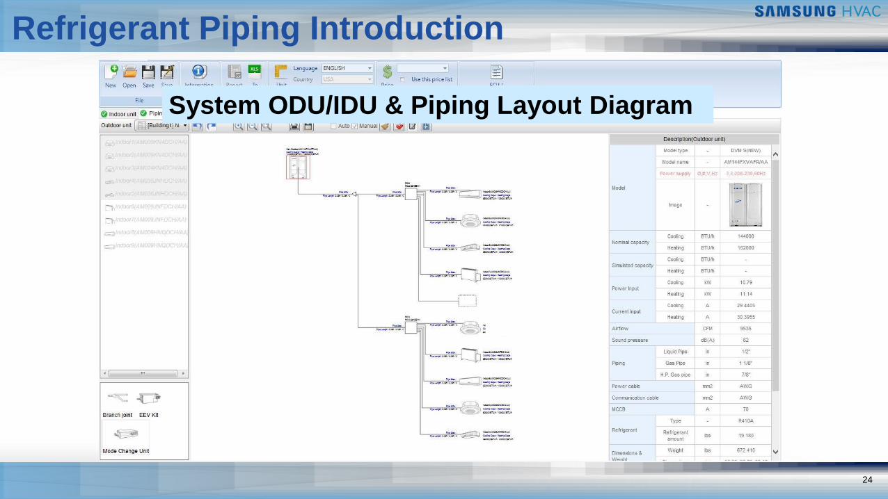
System ODU/IDU & Piping Layout Diagram
Refrigerant Piping Introduction
25
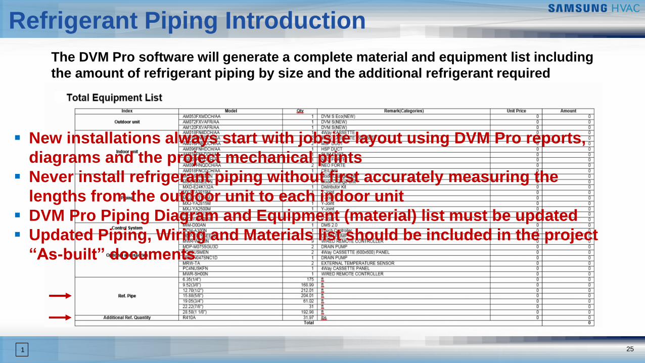
The DVM Pro software will generate a complete material and equipment list including
the amount of refrigerant piping by size and the additional refrigerant required
▪ New installations always start with jobsite layout using DVM Pro reports,
diagrams and the project mechanical prints
▪ Never install refrigerant piping without first accurately measuring the
lengths from the outdoor unit to each indoor unit
▪ DVM Pro Piping Diagram and Equipment (material) list must be updated
▪ Updated Piping, Wiring and Materials list should be included in the project
“As-built” documents
1

DVM S
Field Piping Components
Field Piping Components
27
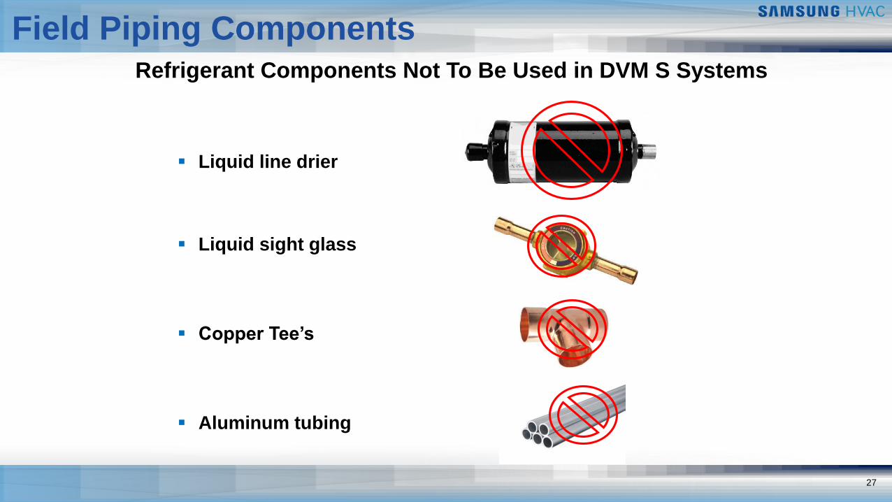
Refrigerant Components Not To Be Used in DVM S Systems
▪ Liquid line drier
▪ Liquid sight glass
▪ Copper Tee’s
▪ Aluminum tubing
28
Field Piping Components
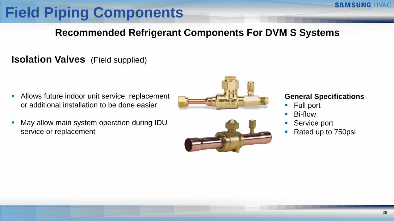
Recommended Refrigerant Components For DVM S Systems
Isolation Valves (Field supplied)
▪ Allows future indoor unit service, replacement
or additional installation to be done easier
▪ May allow main system operation during IDU
service or replacement
General Specifications
▪ Full port
▪ Bi-flow
▪ Service port
▪ Rated up to 750psi
29
Field Piping Components
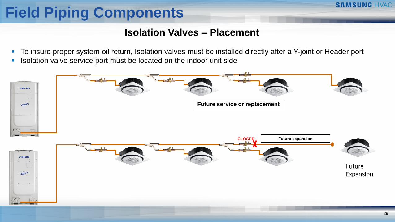
Isolation Valves – Placement
▪ To insure proper system oil return, Isolation valves must be installed directly after a Y-joint or Header port
▪ Isolation valve service port must be located on the indoor unit side
Future service or replacement
CLOSED
Future Expansion
Future expansion
30
Field Piping Components
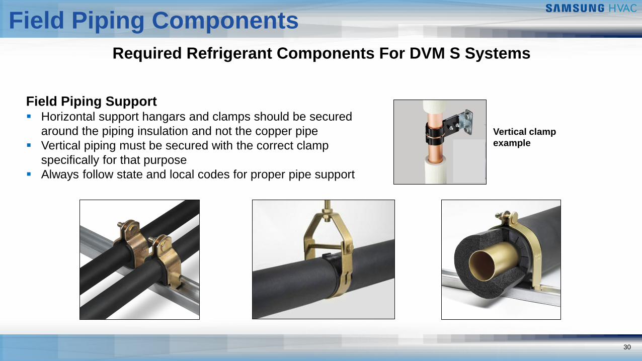
Required Refrigerant Components For DVM S Systems
Field Piping Support▪ Horizontal support hangars and clamps should be secured
around the piping insulation and not the copper pipe
▪ Vertical piping must be secured with the correct clamp
specifically for that purpose
▪ Always follow state and local codes for proper pipe support
Vertical clamp
example
31
Field Piping Components
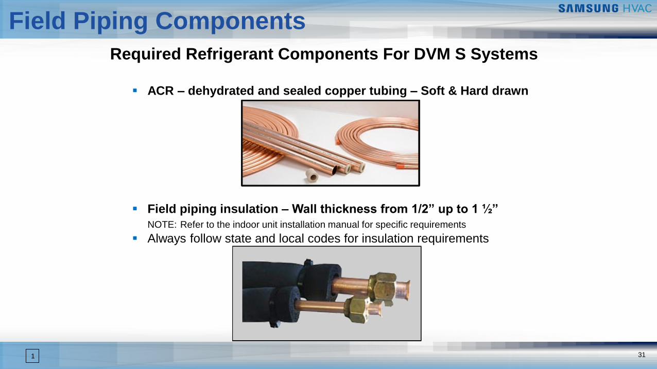
Required Refrigerant Components For DVM S Systems
▪ ACR – dehydrated and sealed copper tubing – Soft & Hard drawn
▪ Field piping insulation – Wall thickness from 1/2” up to 1 ½”
NOTE: Refer to the indoor unit installation manual for specific requirements
▪ Always follow state and local codes for insulation requirements
1
32
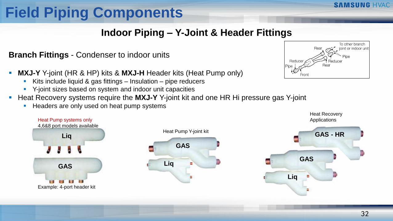
GAS
Liq
Example: 4-port header kit
Heat Pump systems only
4,6&8 port models available
GAS
Liq
Heat Pump Y-joint kit
GAS
Liq
GAS - HR
Heat Recovery
Applications
Branch Fittings - Condenser to indoor units
▪ MXJ-Y Y-joint (HR & HP) kits & MXJ-H Header kits (Heat Pump only)▪ Kits include liquid & gas fittings – Insulation – pipe reducers
▪ Y-joint sizes based on system and indoor unit capacities
▪ Heat Recovery systems require the MXJ-Y Y-joint kit and one HR Hi pressure gas Y-joint▪ Headers are only used on heat pump systems
Indoor Piping – Y-Joint & Header Fittings
Field Piping Components
33
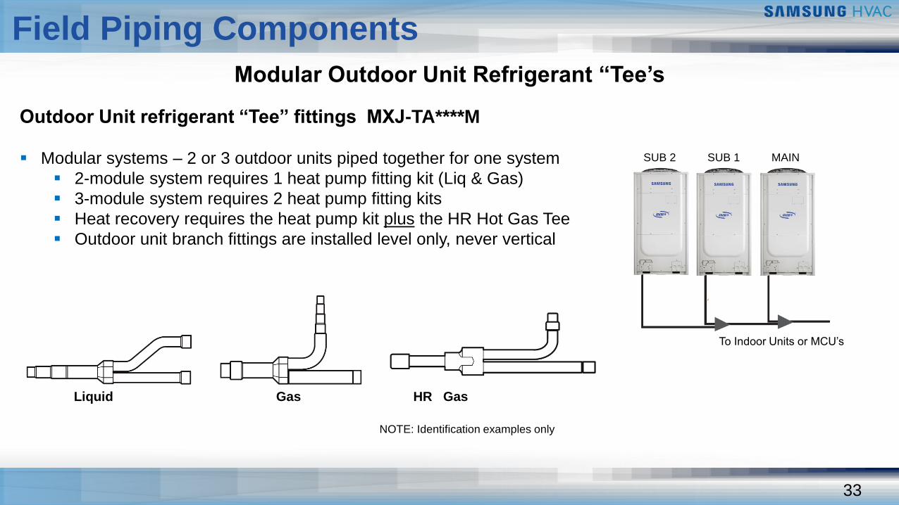
Outdoor Unit refrigerant “Tee” fittings MXJ-TA****M
▪ Modular systems – 2 or 3 outdoor units piped together for one system
▪ 2-module system requires 1 heat pump fitting kit (Liq & Gas)
▪ 3-module system requires 2 heat pump fitting kits
▪ Heat recovery requires the heat pump kit plus the HR Hot Gas Tee
▪ Outdoor unit branch fittings are installed level only, never vertical
Liquid Gas HR Gas
Modular Outdoor Unit Refrigerant “Tee’s
NOTE: Identification examples only
SUB 2 SUB 1 MAIN
To Indoor Units or MCU’s
Field Piping Components
DVM S
Piping Installation Tools
35
Piping Installation Tools
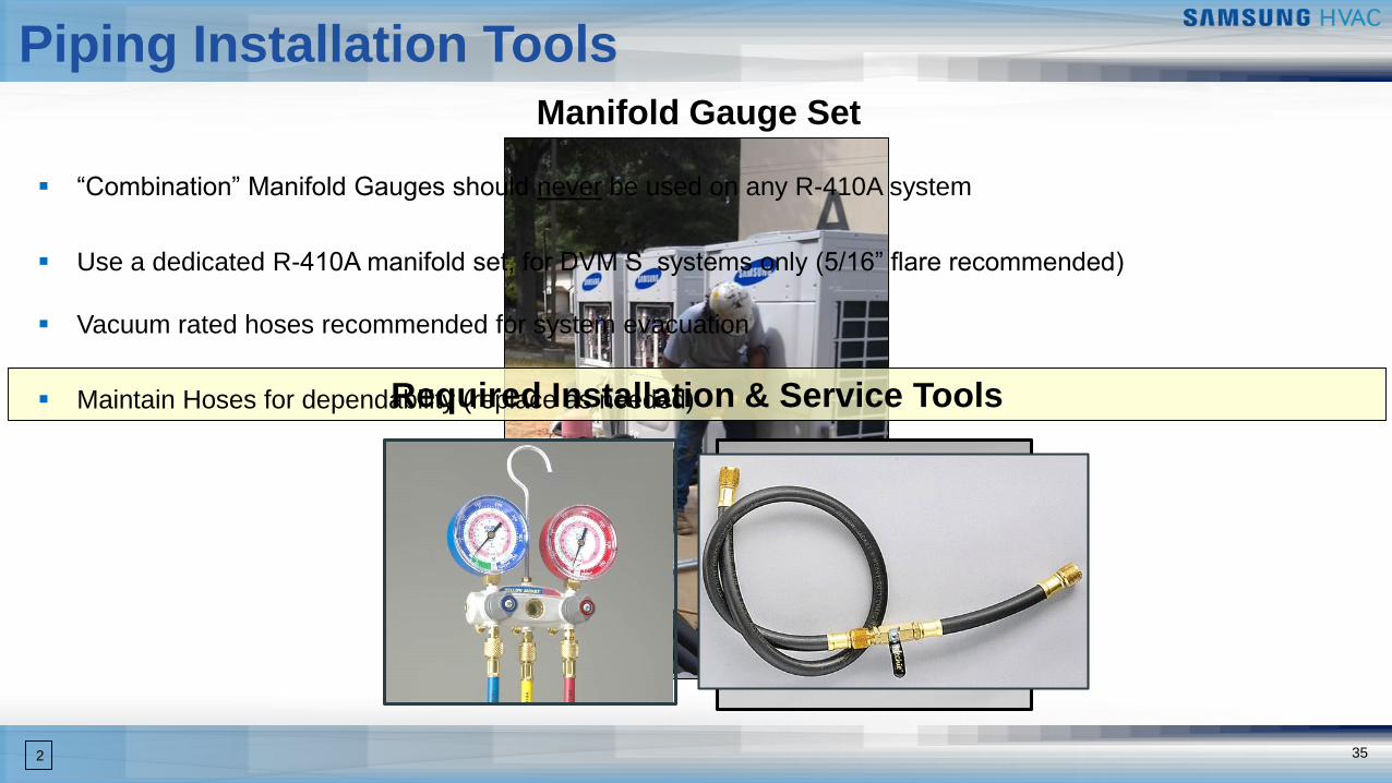
Required Installation & Service Tools
▪ “Combination” Manifold Gauges should never be used on any R-410A system
▪ Use a dedicated R-410A manifold set, for DVM S systems only (5/16” flare recommended)
▪ Vacuum rated hoses recommended for system evacuation
▪ Maintain Hoses for dependability (replace as needed)
2
Manifold Gauge Set
36
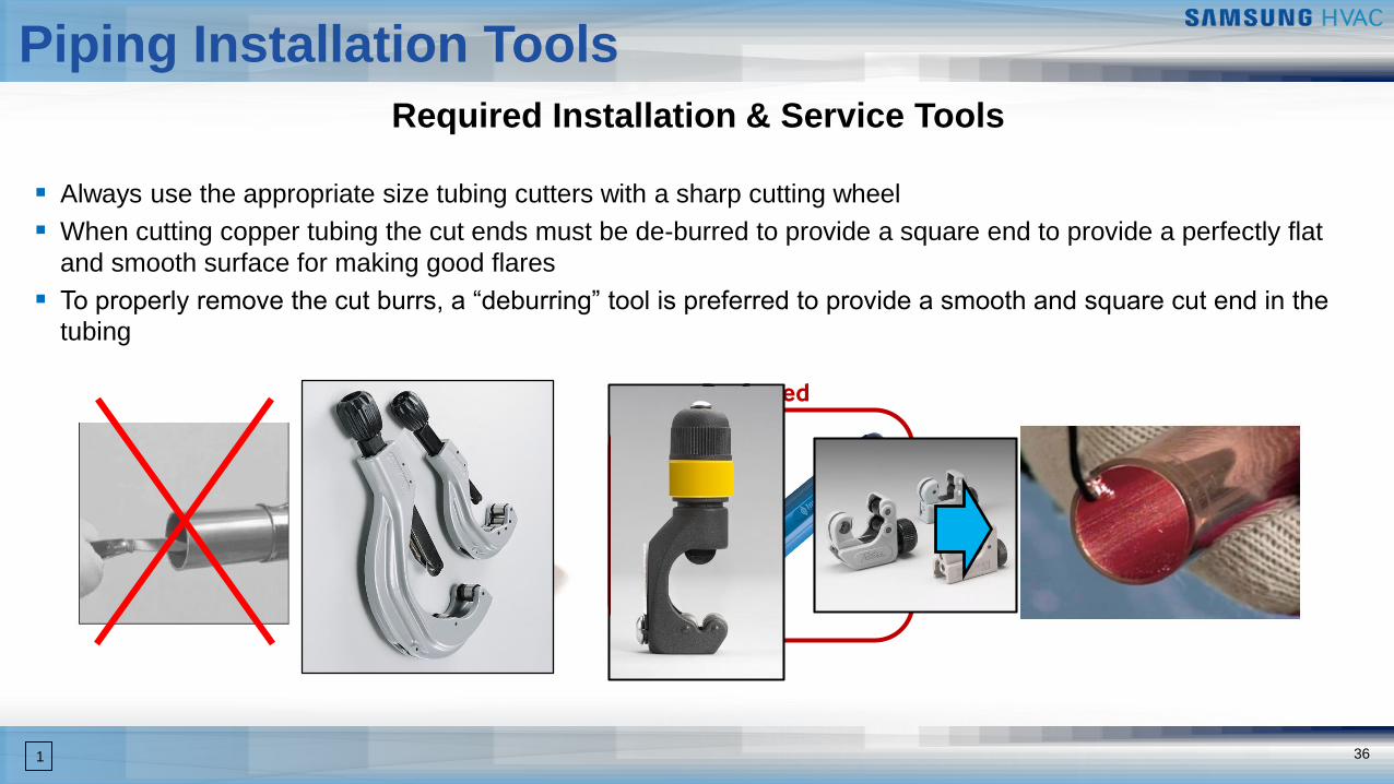
Required Installation & Service Tools
▪ Always use the appropriate size tubing cutters with a sharp cutting wheel
▪ When cutting copper tubing the cut ends must be de-burred to provide a square end to provide a perfectly flat
and smooth surface for making good flares
▪ To properly remove the cut burrs, a “deburring” tool is preferred to provide a smooth and square cut end in the
tubing
Preferred
1
Piping Installation Tools
37
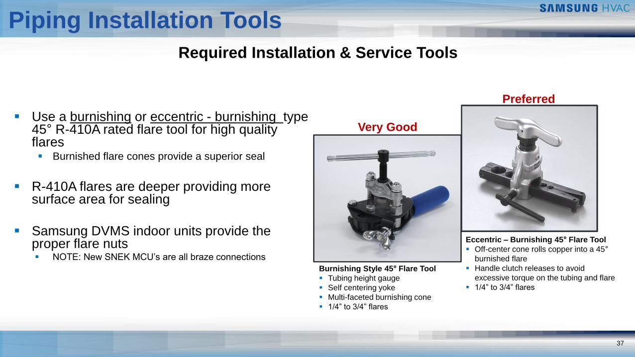
Required Installation & Service Tools
▪ Use a burnishing or eccentric - burnishing type 45° R-410A rated flare tool for high quality flares▪ Burnished flare cones provide a superior seal
▪ R-410A flares are deeper providing more surface area for sealing
▪ Samsung DVMS indoor units provide the proper flare nuts▪ NOTE: New SNEK MCU’s are all braze connections
Burnishing Style 45° Flare Tool
▪ Tubing height gauge
▪ Self centering yoke
▪ Multi-faceted burnishing cone
▪ 1/4” to 3/4” flares
Eccentric – Burnishing 45° Flare Tool
▪ Off-center cone rolls copper into a 45°
burnished flare
▪ Handle clutch releases to avoid
excessive torque on the tubing and flare
▪ 1/4” to 3/4” flares
Preferred
Very Good
Piping Installation Tools
38
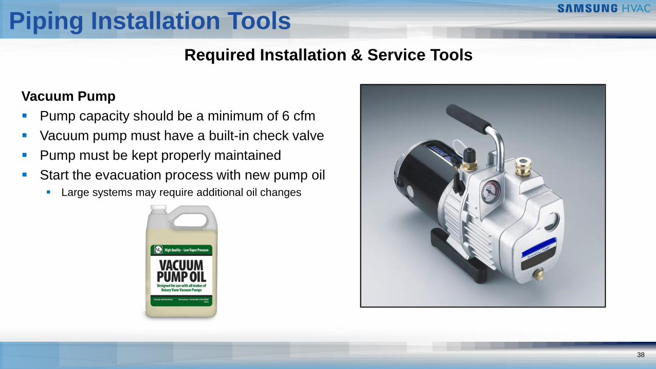
Required Installation & Service Tools
Vacuum Pump
▪ Pump capacity should be a minimum of 6 cfm
▪ Vacuum pump must have a built-in check valve
▪ Pump must be kept properly maintained
▪ Start the evacuation process with new pump oil
▪ Large systems may require additional oil changes
Piping Installation Tools
39
Required Installation & Service Tools
490m
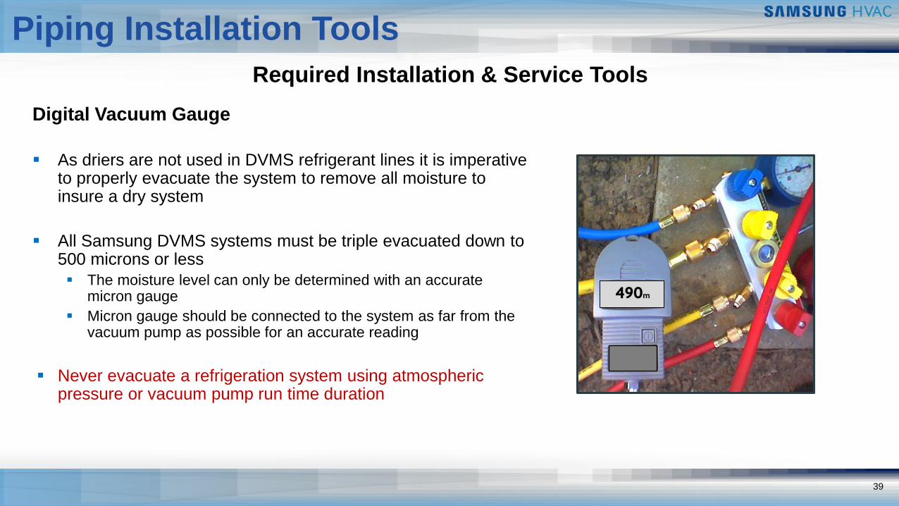
Digital Vacuum Gauge
▪ As driers are not used in DVMS refrigerant lines it is imperative to properly evacuate the system to remove all moisture to insure a dry system
▪ All Samsung DVMS systems must be triple evacuated down to 500 microns or less
▪ The moisture level can only be determined with an accurate micron gauge
▪ Micron gauge should be connected to the system as far from the vacuum pump as possible for an accurate reading
▪ Never evacuate a refrigeration system using atmospheric pressure or vacuum pump run time duration
Piping Installation Tools
40
Required Installation & Service Tools
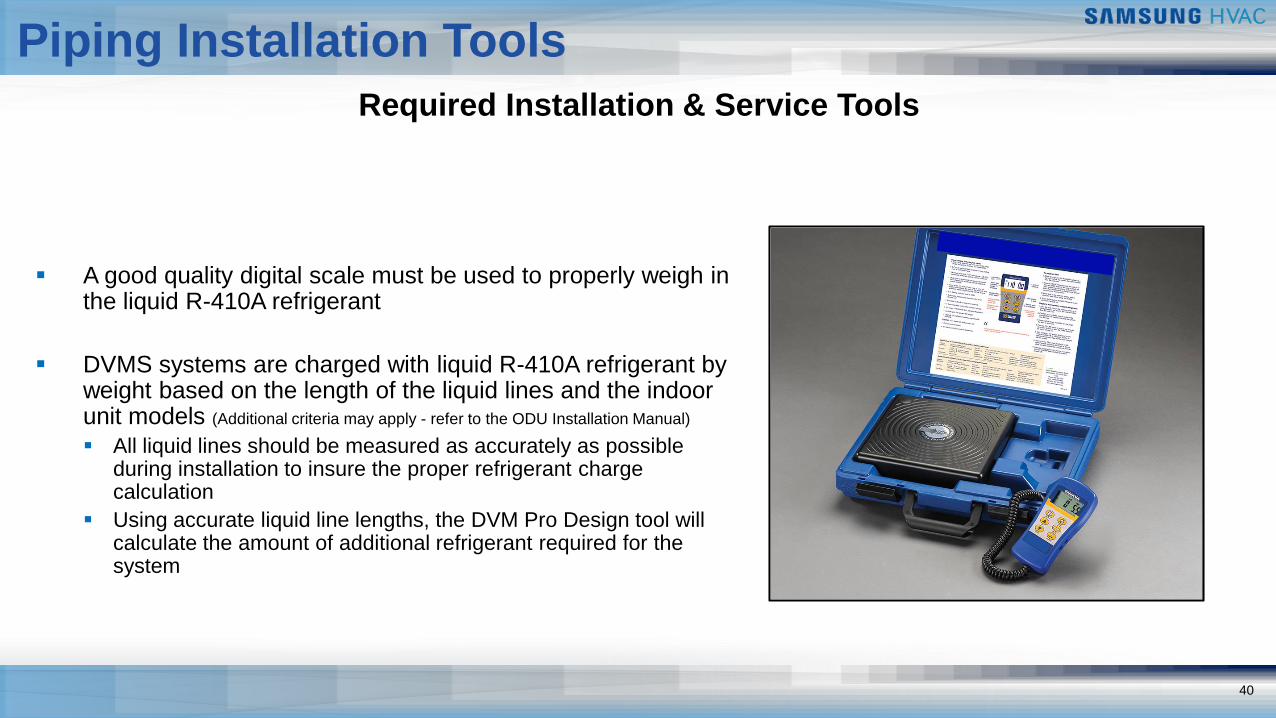
▪ A good quality digital scale must be used to properly weigh in the liquid R-410A refrigerant
▪ DVMS systems are charged with liquid R-410A refrigerant by weight based on the length of the liquid lines and the indoor unit models (Additional criteria may apply - refer to the ODU Installation Manual)
▪ All liquid lines should be measured as accurately as possible during installation to insure the proper refrigerant charge calculation
▪ Using accurate liquid line lengths, the DVM Pro Design tool will calculate the amount of additional refrigerant required for the system
Piping Installation Tools
41
Required Installation & Service Tools
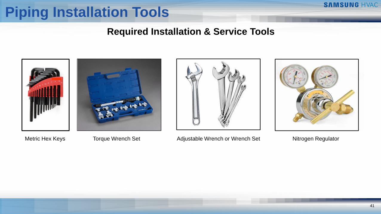
Metric Hex Keys Torque Wrench Set Adjustable Wrench or Wrench Set Nitrogen Regulator
Piping Installation Tools
42
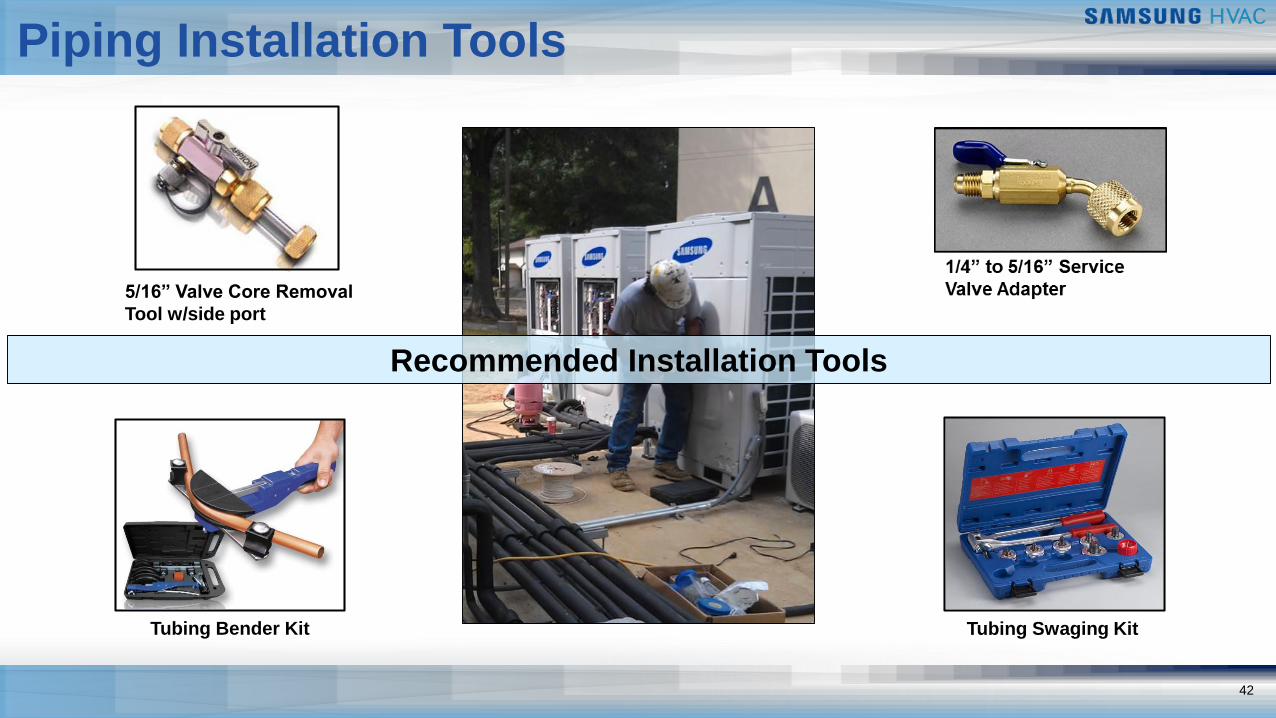
Recommended Installation Tools
5/16” Valve Core Removal
Tool w/side port
Tubing Bender Kit Tubing Swaging Kit
Piping Installation Tools
DVM S
Field Piping Installation
44
Field Piping Installation
Y-joint Installation Guidelines
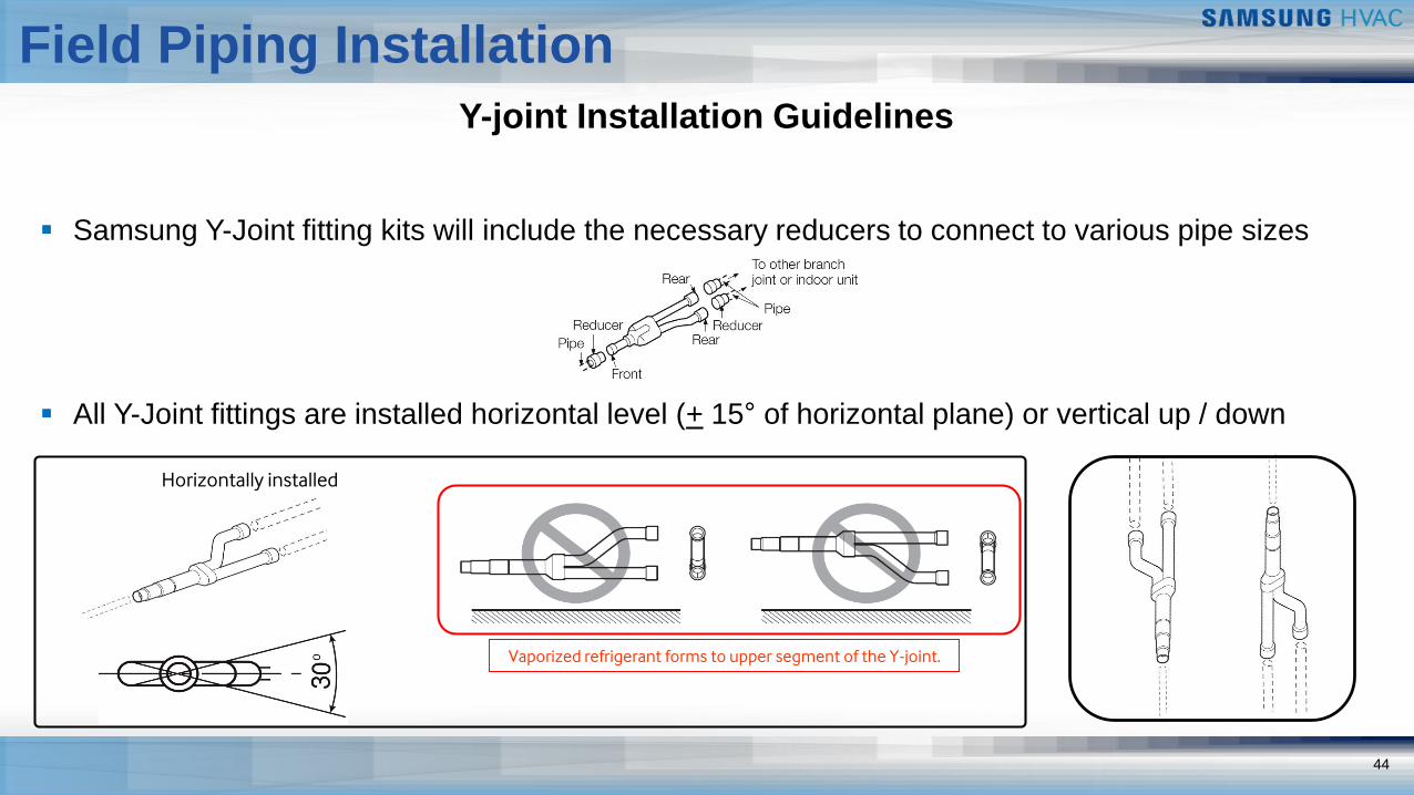
▪ Samsung Y-Joint fitting kits will include the necessary reducers to connect to various pipe sizes
▪ All Y-Joint fittings are installed horizontal level (+ 15° of horizontal plane) or vertical up / down
Horizontally installed
Vaporized refrigerant forms to upper segment of the Y-joint.
45
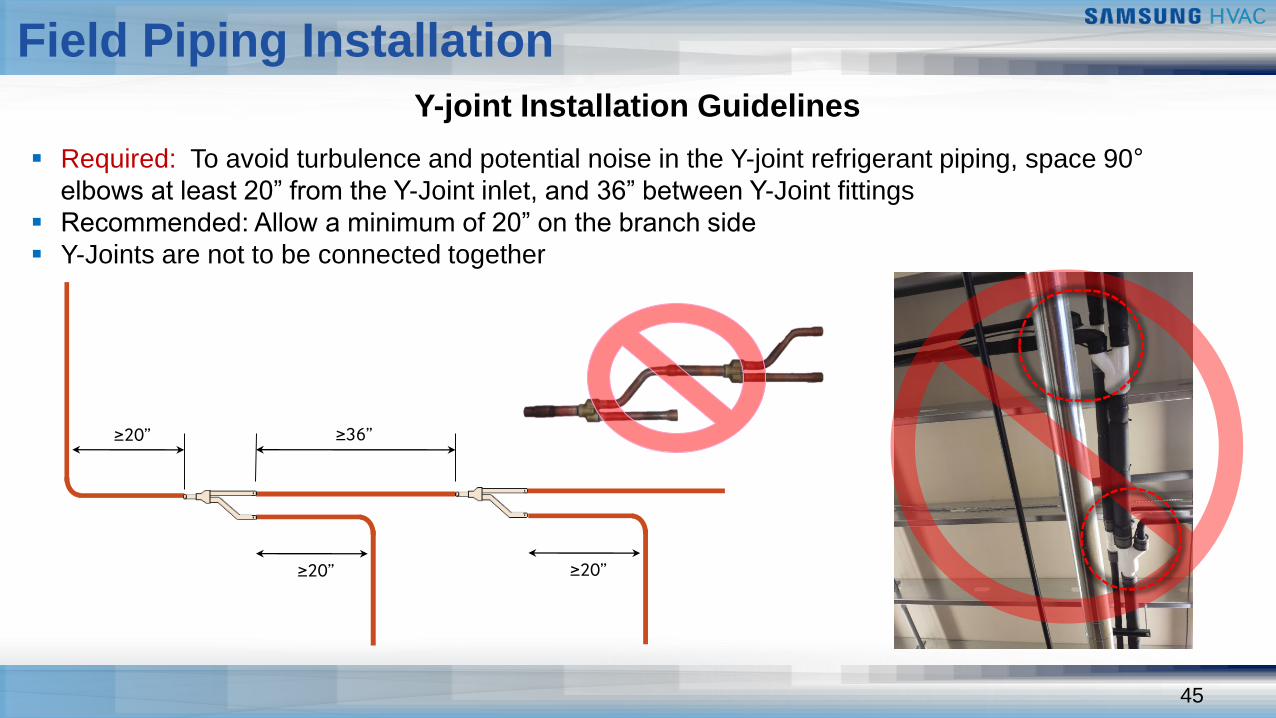
▪ Required: To avoid turbulence and potential noise in the Y-joint refrigerant piping, space 90°
elbows at least 20” from the Y-Joint inlet, and 36” between Y-Joint fittings
▪ Recommended: Allow a minimum of 20” on the branch side
▪ Y-Joints are not to be connected together
Y-joint Installation Guidelines
≥20”
≥36”≥20”
≥20”
Field Piping Installation
461
Field Piping Installation
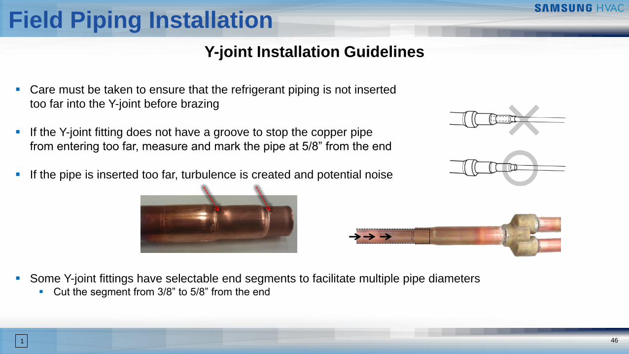
▪ Care must be taken to ensure that the refrigerant piping is not inserted
too far into the Y-joint before brazing
▪ If the Y-joint fitting does not have a groove to stop the copper pipe
from entering too far, measure and mark the pipe at 5/8” from the end
▪ If the pipe is inserted too far, turbulence is created and potential noise
▪ Some Y-joint fittings have selectable end segments to facilitate multiple pipe diameters▪ Cut the segment from 3/8” to 5/8” from the end
Y-joint Installation Guidelines
47
Field Piping Installation
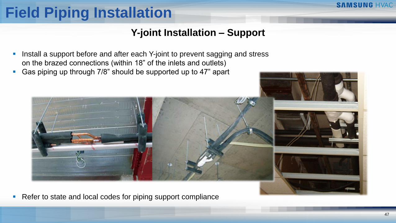
Y-joint Installation – Support
▪ Install a support before and after each Y-joint to prevent sagging and stress
on the brazed connections (within 18” of the inlets and outlets)
▪ Gas piping up through 7/8” should be supported up to 47” apart
▪ Refer to state and local codes for piping support compliance
48
Field Piping Installation
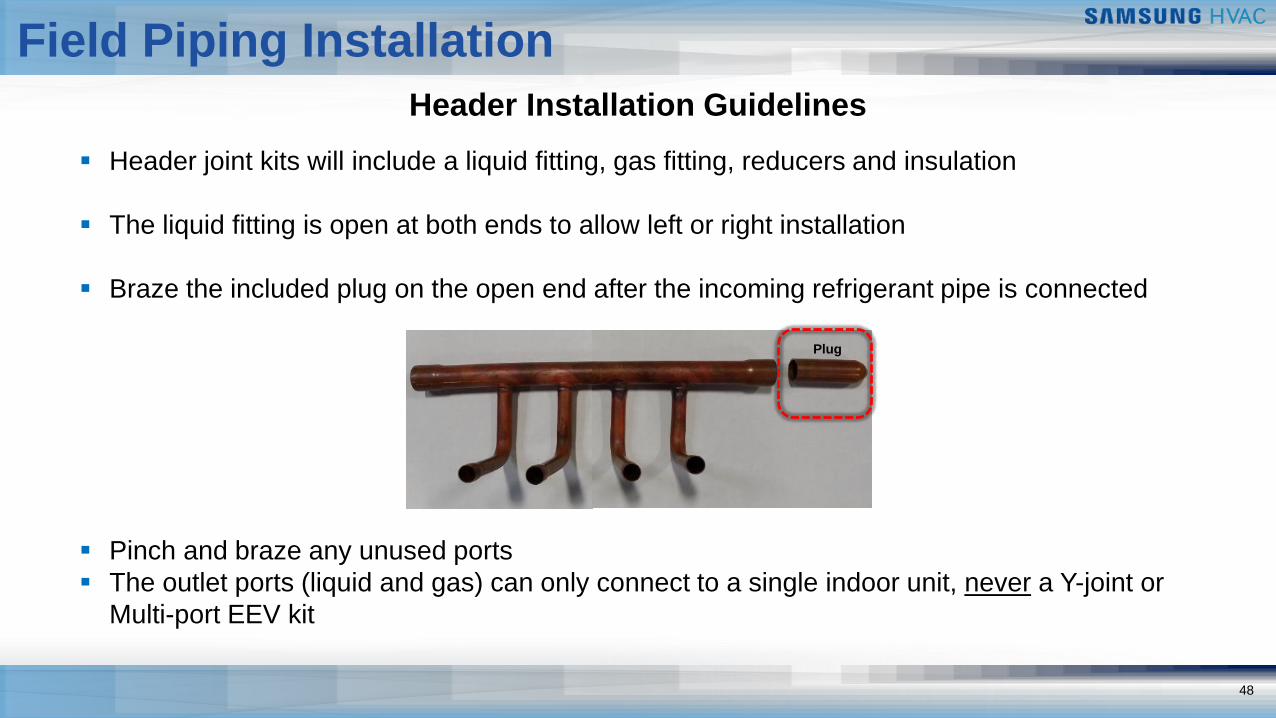
Header Installation Guidelines
▪ Header joint kits will include a liquid fitting, gas fitting, reducers and insulation
▪ The liquid fitting is open at both ends to allow left or right installation
▪ Braze the included plug on the open end after the incoming refrigerant pipe is connected
▪ Pinch and braze any unused ports
▪ The outlet ports (liquid and gas) can only connect to a single indoor unit, never a Y-joint or
Multi-port EEV kit
Plug
49
Field Piping Installation
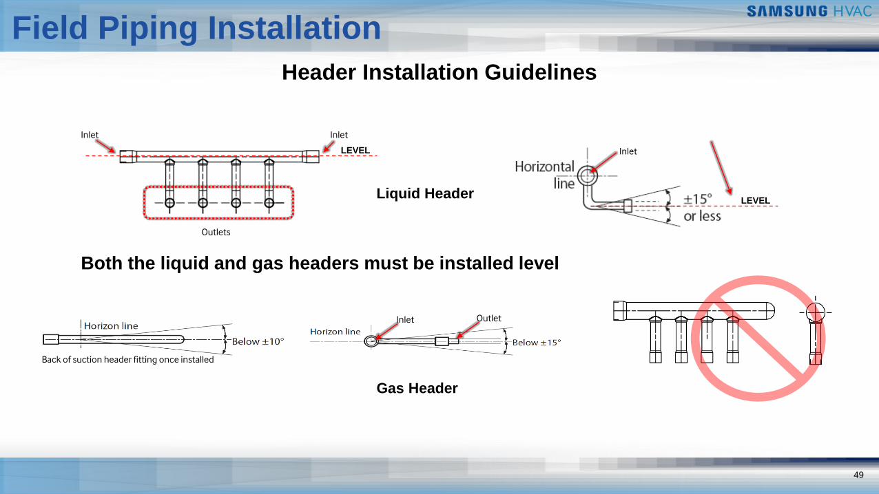
Header Installation Guidelines
Inlet Inlet
Outlets
LEVEL
LEVEL
Inlet
Both the liquid and gas headers must be installed level
Inlet Outlet
Back of suction header fitting once installed
Liquid Header
Gas Header
50
Field Piping Installation
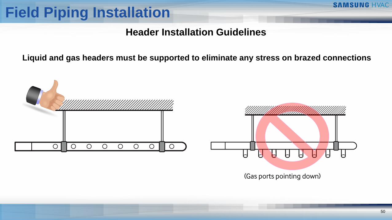
Header Installation Guidelines
(Gas ports pointing down)
Liquid and gas headers must be supported to eliminate any stress on brazed connections
51
Field Piping Installation
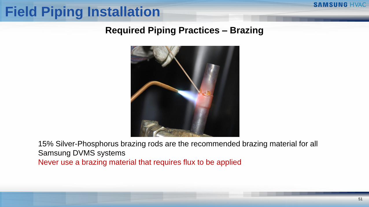
Required Piping Practices – Brazing
15% Silver-Phosphorus brazing rods are the recommended brazing material for all
Samsung DVMS systems
Never use a brazing material that requires flux to be applied
52
Field Piping Installation
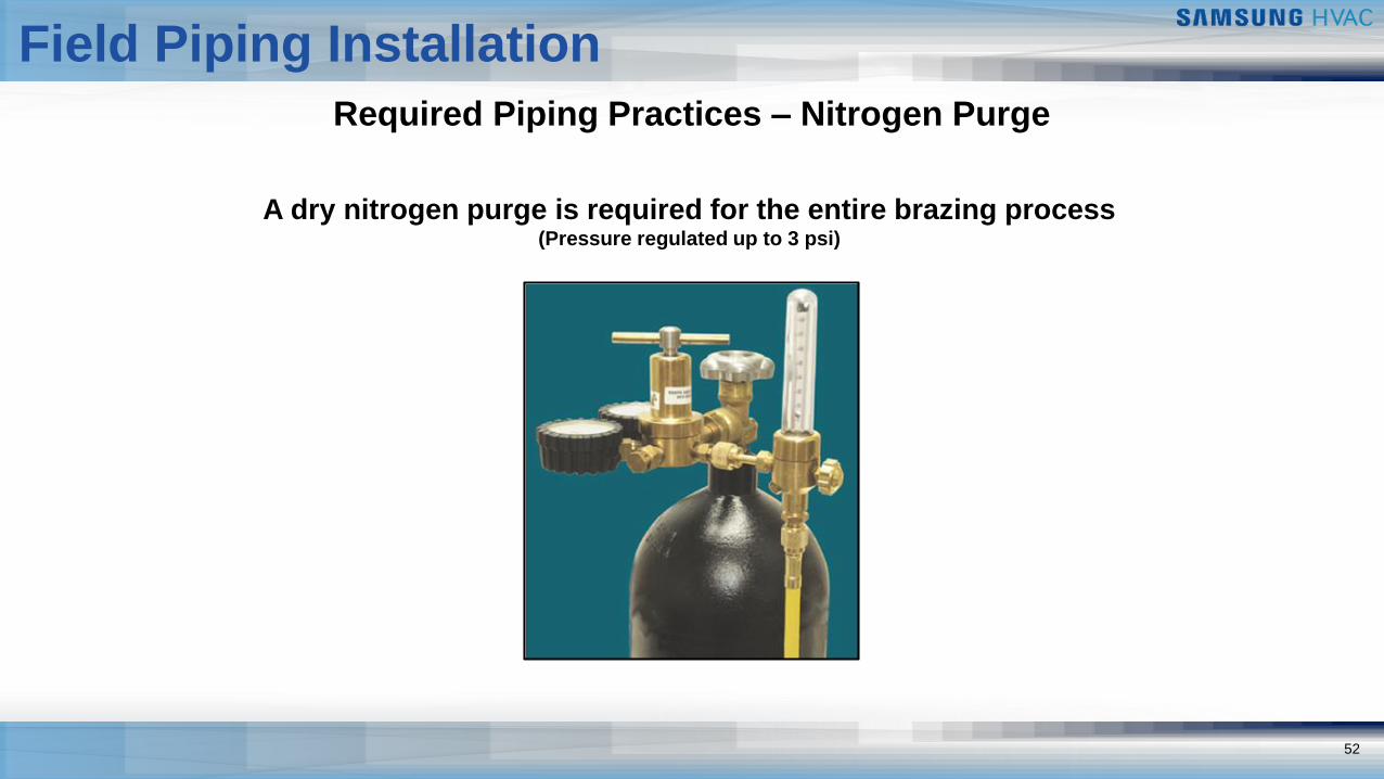
Required Piping Practices – Nitrogen Purge
A dry nitrogen purge is required for the entire brazing process (Pressure regulated up to 3 psi)
53
Field Piping Installation
Required Piping Practices – Nitrogen Purge
▪ Using a flow regulator, maintain 2 – 3 PSI) of dry nitrogen pressure
▪ If you are having difficulty maintaining this, partially cover the opposite end of the pipe with tape
to maintain pressure
▪ If flow is too low, oxidation will still form within the tubing
▪ If flow is too high, it will be difficult to make a quality brazed connection
▪ Maintain nitrogen flow after brazing is complete until piping cools
541
Field Piping Installation
Required Piping Practices – Nitrogen Purge
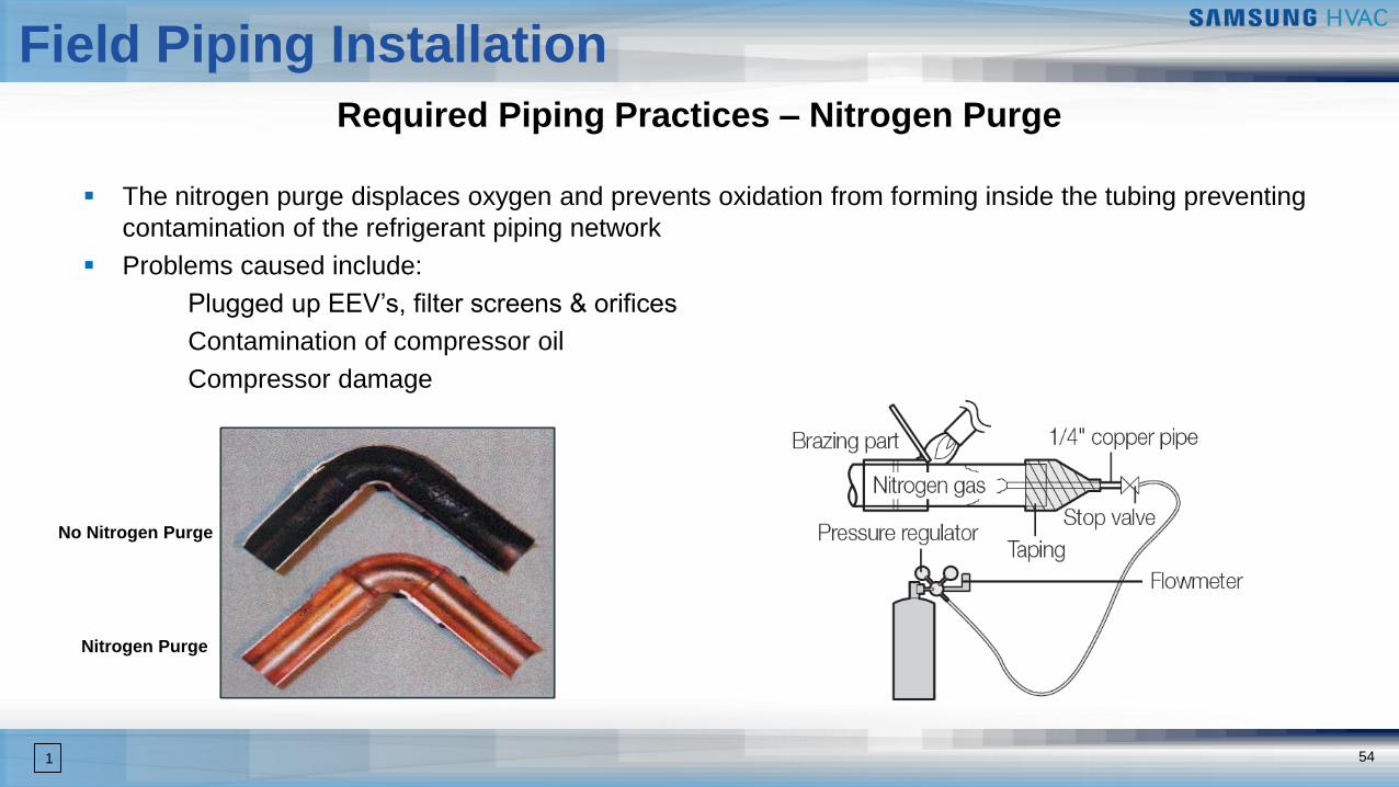
▪ The nitrogen purge displaces oxygen and prevents oxidation from forming inside the tubing preventing
contamination of the refrigerant piping network
▪ Problems caused include:
Plugged up EEV’s, filter screens & orifices
Contamination of compressor oil
Compressor damage
Nitrogen Purge
No Nitrogen Purge
55
Field Piping Installation
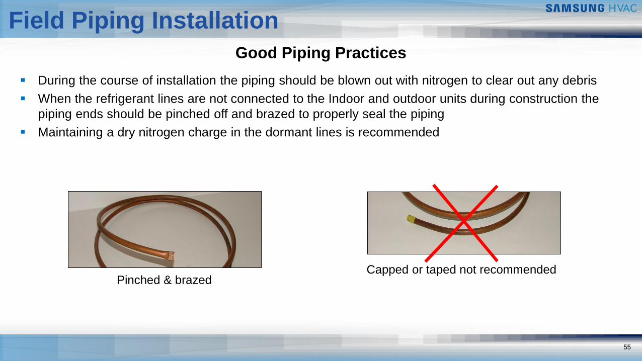
Good Piping Practices
Pinched & brazed
▪ During the course of installation the piping should be blown out with nitrogen to clear out any debris
▪ When the refrigerant lines are not connected to the Indoor and outdoor units during construction the
piping ends should be pinched off and brazed to properly seal the piping
▪ Maintaining a dry nitrogen charge in the dormant lines is recommended
Capped or taped not recommended
56
Field Piping Installation
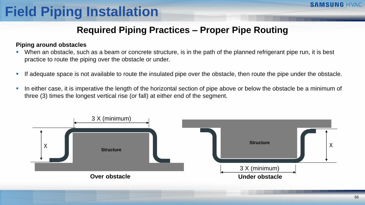
Required Piping Practices – Proper Pipe Routing
Piping around obstacles
▪ When an obstacle, such as a beam or concrete structure, is in the path of the planned refrigerant pipe run, it is best
practice to route the piping over the obstacle or under.
▪ If adequate space is not available to route the insulated pipe over the obstacle, then route the pipe under the obstacle.
▪ In either case, it is imperative the length of the horizontal section of pipe above or below the obstacle be a minimum of
three (3) times the longest vertical rise (or fall) at either end of the segment.
X
3 X (minimum)
Over obstacle
3 X (minimum)
X
Under obstacle
Structure
Structure
57
Field Piping Installation
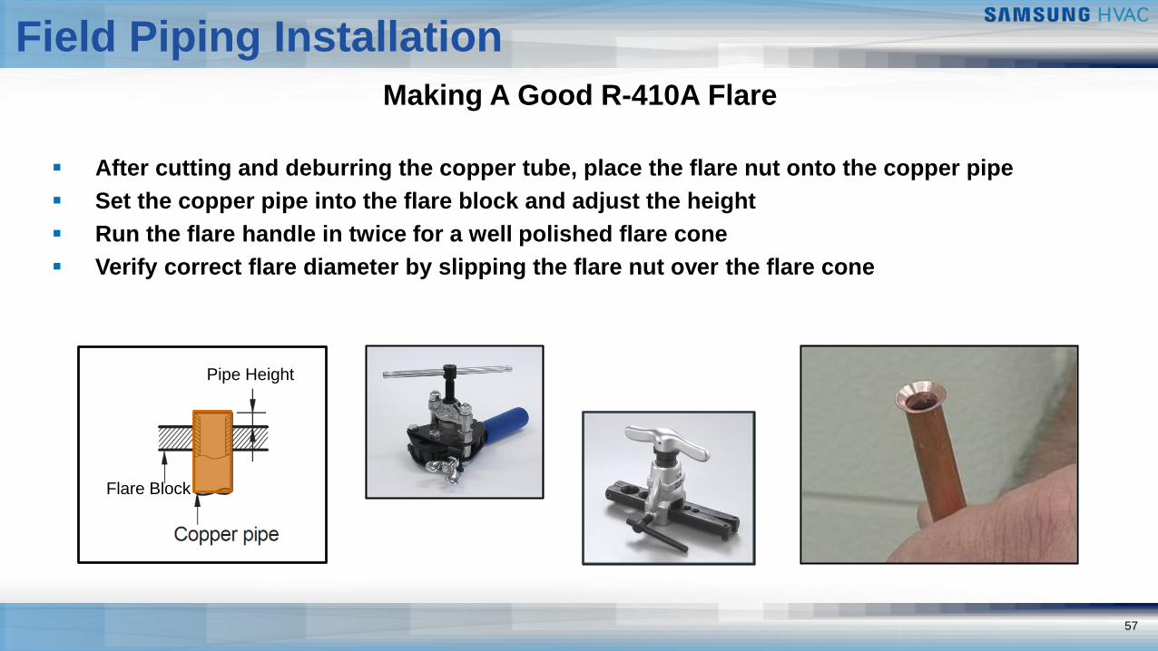
Making A Good R-410A Flare
▪ After cutting and deburring the copper tube, place the flare nut onto the copper pipe
▪ Set the copper pipe into the flare block and adjust the height
▪ Run the flare handle in twice for a well polished flare cone
▪ Verify correct flare diameter by slipping the flare nut over the flare cone
Flare Block
Pipe Height
58
Field Piping Installation
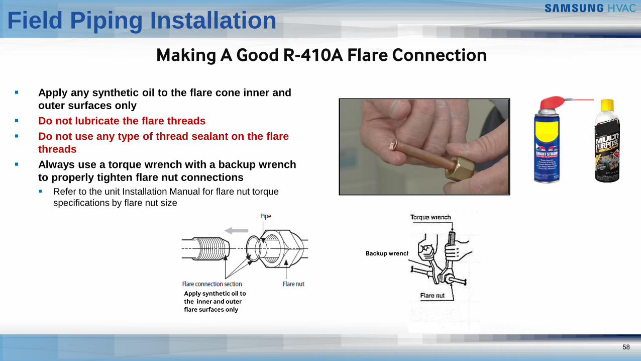
Making A Good R-410A Flare Connection
▪ Apply any synthetic oil to the flare cone inner and
outer surfaces only
▪ Do not lubricate the flare threads
▪ Do not use any type of thread sealant on the flare
threads
▪ Always use a torque wrench with a backup wrench
to properly tighten flare nut connections
▪ Refer to the unit Installation Manual for flare nut torque
specifications by flare nut size
Apply synthetic oil to the inner and outer flare surfaces only
Backup wrench
System 3 Step Nitrogen Pressure Test
59
Field Piping Installation
Required Piping Practices – High Pressure Leak Test
600 psi
24 Hr
3
5 Min
100 psi
1
300 psi
5 Min
2
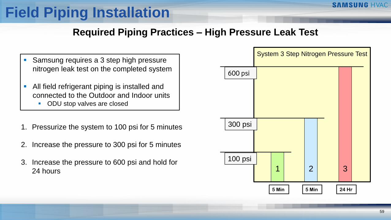
▪ Samsung requires a 3 step high pressure
nitrogen leak test on the completed system
▪ All field refrigerant piping is installed and
connected to the Outdoor and Indoor units▪ ODU stop valves are closed
1. Pressurize the system to 100 psi for 5 minutes
2. Increase the pressure to 300 psi for 5 minutes
3. Increase the pressure to 600 psi and hold for
24 hours
60
Field Piping Installation
Required Piping Practices –Leak Test Pressure Drop
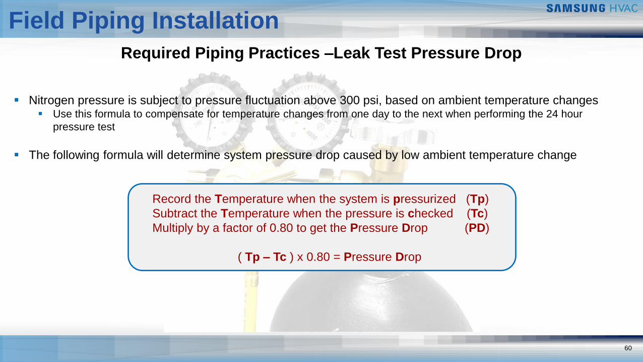
Record the Temperature when the system is pressurized (Tp)
Subtract the Temperature when the pressure is checked (Tc)
Multiply by a factor of 0.80 to get the Pressure Drop (PD)
( Tp – Tc ) x 0.80 = Pressure Drop
▪ Nitrogen pressure is subject to pressure fluctuation above 300 psi, based on ambient temperature changes▪ Use this formula to compensate for temperature changes from one day to the next when performing the 24 hour
pressure test
▪ The following formula will determine system pressure drop caused by low ambient temperature change
61
Field Piping Installation
Required Piping Practices – High Pressure Leak Test
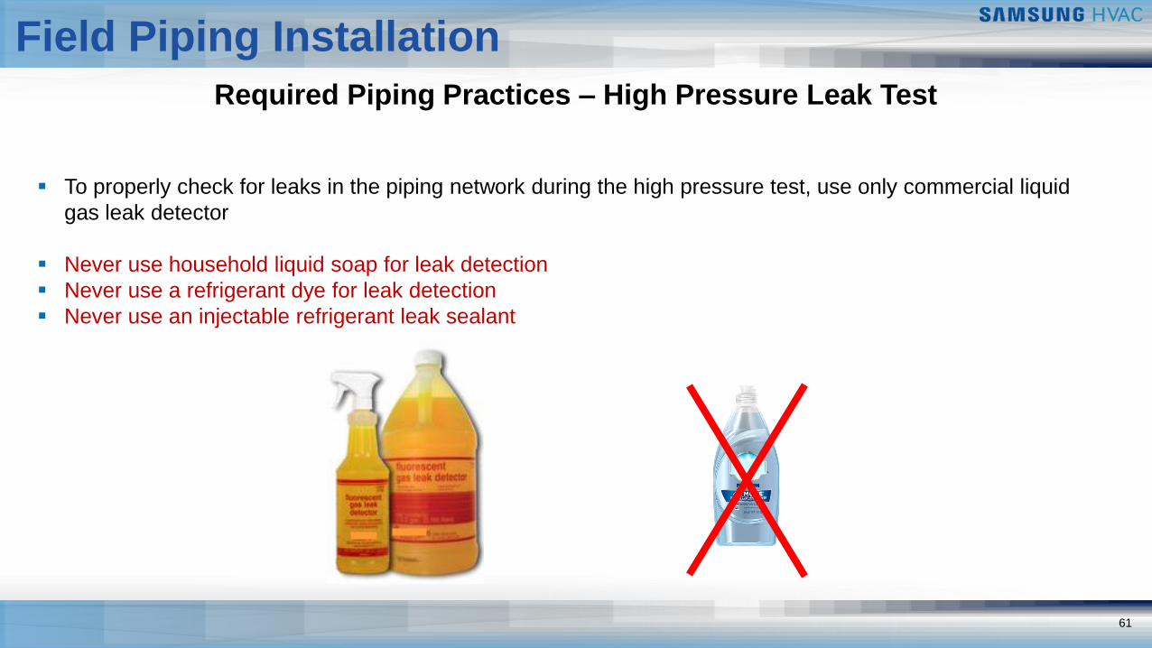
▪ To properly check for leaks in the piping network during the high pressure test, use only commercial liquid
gas leak detector
▪ Never use household liquid soap for leak detection
▪ Never use a refrigerant dye for leak detection
▪ Never use an injectable refrigerant leak sealant
62
Field Piping Installation
Required Piping Practices – System Evacuation
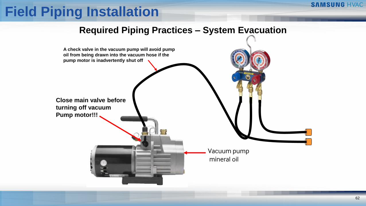
Vacuum pumpmineral oil
Close main valve before
turning off vacuum
Pump motor!!!
A check valve in the vacuum pump will avoid pump
oil from being drawn into the vacuum hose if the
pump motor is inadvertently shut off
633
Field Piping Installation
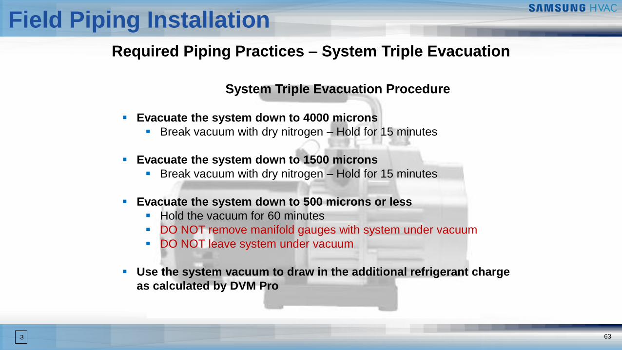
Required Piping Practices – System Triple Evacuation
System Triple Evacuation Procedure
▪ Evacuate the system down to 4000 microns
▪ Break vacuum with dry nitrogen – Hold for 15 minutes
▪ Evacuate the system down to 1500 microns
▪ Break vacuum with dry nitrogen – Hold for 15 minutes
▪ Evacuate the system down to 500 microns or less
▪ Hold the vacuum for 60 minutes
▪ DO NOT remove manifold gauges with system under vacuum
▪ DO NOT leave system under vacuum
▪ Use the system vacuum to draw in the additional refrigerant charge
as calculated by DVM Pro
DVM S
Additional Guidelines
65
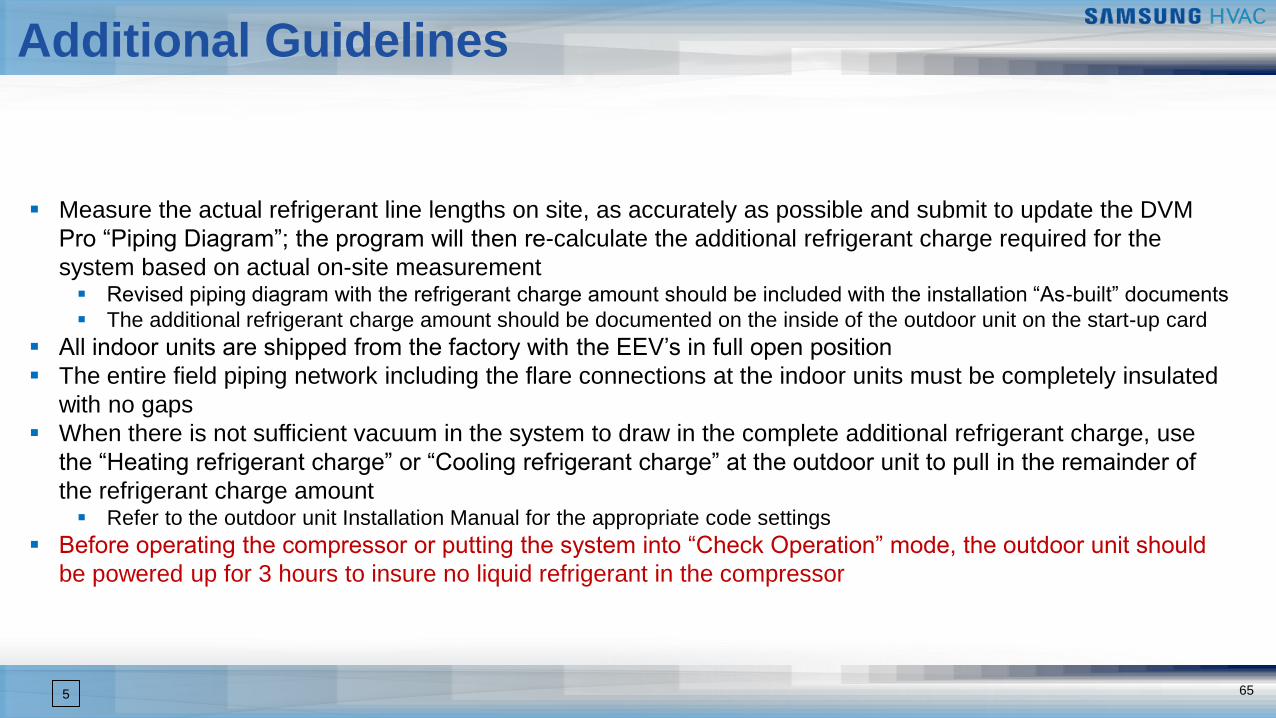
Additional Guidelines
▪ Measure the actual refrigerant line lengths on site, as accurately as possible and submit to update the DVM
Pro “Piping Diagram”; the program will then re-calculate the additional refrigerant charge required for the
system based on actual on-site measurement▪ Revised piping diagram with the refrigerant charge amount should be included with the installation “As-built” documents
▪ The additional refrigerant charge amount should be documented on the inside of the outdoor unit on the start-up card
▪ All indoor units are shipped from the factory with the EEV’s in full open position
▪ The entire field piping network including the flare connections at the indoor units must be completely insulated
with no gaps
▪ When there is not sufficient vacuum in the system to draw in the complete additional refrigerant charge, use
the “Heating refrigerant charge” or “Cooling refrigerant charge” at the outdoor unit to pull in the remainder of
the refrigerant charge amount▪ Refer to the outdoor unit Installation Manual for the appropriate code settings
▪ Before operating the compressor or putting the system into “Check Operation” mode, the outdoor unit should
be powered up for 3 hours to insure no liquid refrigerant in the compressor
5
DVMS Training