Embed Size (px)
Citation preview
DVM CHILLER
Installation manualFCU Application KIT MIM-F00N
• Thank you for purchasing this Samsung Product.
• Before operating this unit, please read this Installation manual carefully and retain it for future reference.
2
Contents
PREPARATION 3
Safety precautions 3
CHECKING BEFORE THE INSTALLATION 7
Checking before the installation 7
Accessories 7
Net dimension 7
Name of the parts 8
Diagram of DMS 2.5 and DVM CHILLER & FCU 9
Diagram of BMS and DVM CHILLER & FCU 10
INSTALLATION 12
FCU KIT installation 12
FCU KIT installation 12
Wiring work 15
Functions of FCU KIT 19
Diagram of ASS'Y control 21
Installing water temperature sensor 26
SETTING 28
Setting address of FCU KIT and installation option 28
Procedure of option setting 28
Setting an option 29
Setting address (MAIN/RMC) of FCU KIT 34
Setting FCU KIT installation option 35
Changing a particular option 43
OTHERS 44
Troubleshooting 44
Error code 44
Inspection and test operation 45
Checking FCU KIT installation 45
Trial operation 45
Function of wired remote controller 47
Display 47
3
PR
EP
AR
AT
ION
These safety precautions are for owner’s safety and preventions of property damage.
Therefore, please read this manual thoroughly before installing or using your product.
(Please refer to appropriate installation for any optional product installation.)
WARNING
Hazards or unsafe practices that may result in severe personal injury or death.
CAUTION
Hazards or unsafe practices that may result in minor personal injury or property damage.
Follow directions.
Do NOT attempt.
Make sure the machine is grounded to prevent electric shock.
Unplug the power plug from the wall socket.
Do NOT disassemble.
For installation
WARNING
The installation of this product must be performed by a qualified technician or service company. Failure to do so may result in electric shock, fire, product malfunction, or injury.
Connect the power with rated voltage when installing. Failure to do so may result in electric shock, fire, or product malfunction.
Check if the installation was done correctly according to the installation manual. There is risk of electric shock or fire if the product is installed incorrectly.
Make sure that all wiring work is done by qualified person complying regional standards and instructions in this manual. If the installation is done by unqualified person, there is risk of product malfunction,
electric shock or fire caused by incorrect installation.
Contact the service center when you need to dispose the product.
Safety precautions
4
PR
EP
AR
AT
ION
Do not install this product near a heater, inflammable material. Do not install this product in a humid, oily or dusty location, in a location exposed to direct sunlight and water (rain drops). Do not install this product in a location where gas may leak. Potential risk of electric shock or fire.
Do not attempt to move or re-install the product that is already installed. There is risk of electric shock or fire.
Do not attempt to repair, disassemble, or modify the product yourself. There is risk of product damage, electric shock or fire. When repair is needed,
consult service center.
For installation
CAUTION
Install the product on a hard and even place that can support its weight. If the place cannot support its weight, the product may fall down and it may cause
product damage.
Make sure there is no tension to the cable during installation. Cable may get cut and cause fire.
Install the product in a place with temperature between 0 ~ 39 °C (32 ~ 102 °F) with no direct sunlight. If not, there is risk of fire or product malfunction.
Do not install the product in a place where special spray or acid/alkali solution is used. If not, there is risk of fire or product malfunction.
Do not connect the power cable to the communication cable terminal. There is risk of fire.
When installing the product in hospitals or other places, make sure that the product does not interrupt with other products. If not, there is risk of product malfunction.
Do not allow water to enter the product. If not, there is risk of electric shock or fire.
Do not press the buttons with any sharp objects. There is risk of electric shock or damage to the parts.
Safety precautions
5
PR
EP
AR
AT
ION
For power supply
WARNING
Do not pull or excessively bend the power cord. Do not twist or tie the power cord. Potential risk of electric shock or fire.
For operation
WARNING
If the product generates a strange noise, a burning smell or smoke, disconnect the power supply immediately and contact a service center. Potential risk of electric shock or fire.
Contact a service center to reinstall the product. If not, there is risk of product malfunction, water leakage, electric shock or fire.
A delivery service for the product is not provided. If you reinstall the product in
another location, additional construction costs and installation fee will be charged.
When an error appears or the product malfunctions, stop the operation immediately. If the product generates a burning smell or it malfunctions, turn it off and disconnect
the power supply immediately, and then contact a service center. If not, there is risk
of electric shock, fire, or damage to the product.
Do not attempt to repair, disassemble, or modify the product yourself. This may result in electric shock, fire, a product malfunction or injury.
For operation
CAUTION
Do not allow water to enter the product. There is risk of fire or explosion.
6
PR
EP
AR
AT
ION
Do not operate the product with wet hands. There is risk of electric shock.
Do not spray volatile material such as insecticide onto the product. As well as being harmful to humans, this may also result in electric shock, fire or a
product malfunction.
Do not hit or apply excessive force of any kind to the product.
Do not use this product for other purposes. This product is designed to be used only for DVM CHILLER.
Do not press the buttons with any sharp objects. Electric shock or part damage may occur.
For cleaning
WARNING
Do not clean the product by spraying water directly onto it. Do not use benzene, thinner, acetone or alcohol to clean the product. This may result in discoloration, deformation, damage, electric shock or fire.
Safety precautions
7
CH
EC
KIN
G B
EF
OR
E T
HE
INSTA
LLA
TIO
N
Checking before the installation
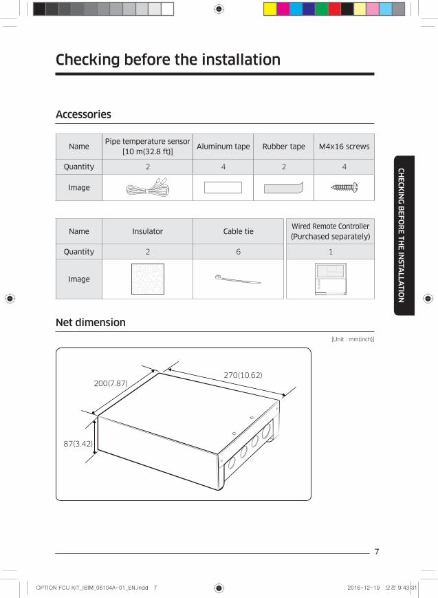
Accessories
NamePipe temperature sensor
[10 m(32.8 ft)]Aluminum tape Rubber tape M4x16 screws
Quantity 2 4 2 4
Image
Name Insulator Cable tieWired Remote Controller (Purchased separately)
Quantity 2 6 1
Image
Net dimension
[Unit : mm(inch)]
200(7.87)270(10.62)
87(3.42)
8
CH
EC
KIN
G B
EF
OR
E T
HE
INSTA
LLA
TIO
N
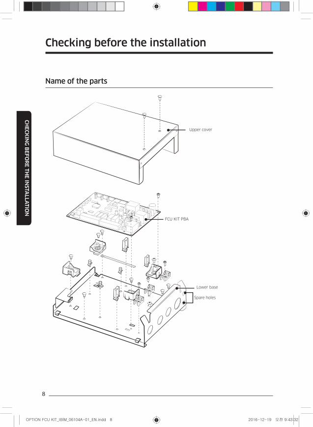
Name of the parts
Upper cover
FCU KIT PBA
Lower base
Spare holes
Checking before the installation
9
CH
EC
KIN
G B
EF
OR
E T
HE
INSTA
LLA
TIO
N
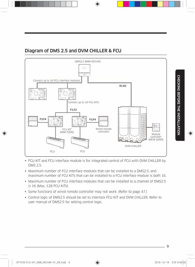
Diagram of DMS 2.5 and DVM CHILLER & FCU
CN4
CN3
RED
CN2
BLK
YELREDY-GRN
CN4
CN3
RED
CN2
BLK
YELREDY-GRN
DMS2.5 (MIM-D01AN)
Connect up to 16 FCU interface modules
R1,R2
Module controller
(MCM-A00N)
Wired remote controller
F3,F4F3,F4
F1,F2
FCU KIT (MIM-F00N)
FCU FCU
Connect up to 16 FCU KITs
DVM CHILLER
FCU KIT and FCU interface module is for integrated control of FCU with DVM CHILLER by
DMS 2.5.
Maximum number of FCU interface modules that can be installed to a DMS2.5, and
maximum number of FCU KITs that can be installed to a FCU interface module is both 16.
Maximum number of FCU interface modules that can be installed to a channel of DMS2.5
is 16 (Max. 128 FCU KITs).
Some functions of wired remote controller may not work. (Refer to page 47.)
Control logic of DMS2.5 should be set to interlock FCU KIT and DVM CHILLER. Refer to
user manual of DMS2.5 for setting control logic.
10
CH
EC
KIN
G B
EF
OR
E T
HE
INSTA
LLA
TIO
N
Checking before the installation
FCU interface module should be installed inside of FCU KIT.
DMS2.0 is not supported.
Cabel Max length
– DMS -FCU interface module : max 1000 m(3280.8 ft)
– FCU interface module -FCU KIT :max 1000 m(3280.8 ft)
CAUTION
• Install FCU that has terminal block to fix power cable by screw. Do not connect power
cable by cutting.
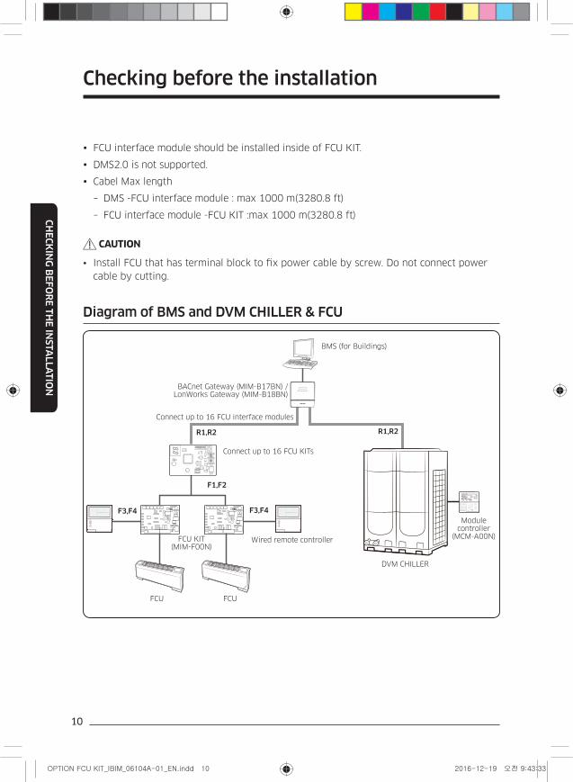
Diagram of BMS and DVM CHILLER & FCU
Connect up to 16 FCU interface modules
CN4
CN3
RED
CN2
BLK
YELREDY-GRN
BMS (for Buildings)
BACnet Gateway (MIM-B17BN) / LonWorks Gateway (MIM-B18BN)
Module controller
(MCM-A00N)Wired remote controller FCU KIT
(MIM-F00N)
DVM CHILLER
Connect up to 16 FCU KITs
FCU FCU
F3,F4 F3,F4
F1,F2
R1,R2 R1,R2
11
CH
EC
KIN
G B
EF
OR
E T
HE
INSTA
LLA
TIO
N
FCU KIT and FCU interface module is for integrated control of FCU with DVM CHILLER by
DMS 2.5.
Maximum number of FCU interface modules that can be installed to a BACnet/LonWorks,
and maximum number of FCU KITs that can be installed to a FCU interface module is
both 16.
Maximum number of FCU interface modules that can be installed to a channel of BACnet/
LonWorks is 16.
Some functions of wired remote controller may not work. (Refer to page 47.)
FCU interface module should be installed inside of FCU KIT.
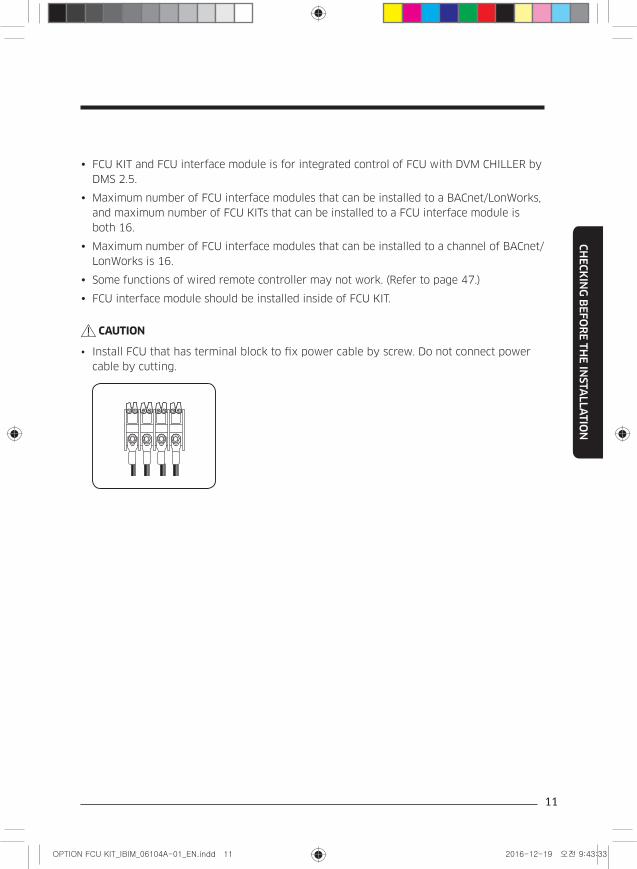
CAUTION
• Install FCU that has terminal block to fix power cable by screw. Do not connect power
cable by cutting.
12
INSTA
LLA
TIO
N
FCU KIT installation
FCU KIT installation
1 Check the location of FCU KIT installation.
Select the installation location that FCU can be fixed (such as wall, etc.) according to
structure of FCU.
2 Select FCU product that has terminal block, and connect power cable of FCU KIT to the terminal block.
3 Select the control type (individual control or integrated control) and install FCU KIT and FCU.
In case of direct power output from FCU KIT to FCU fan motor, select the fan motor which
maximum current is not over 1 A (RMS).
In case of installing multiple FCU to a FCU KIT, install relay for power supply.
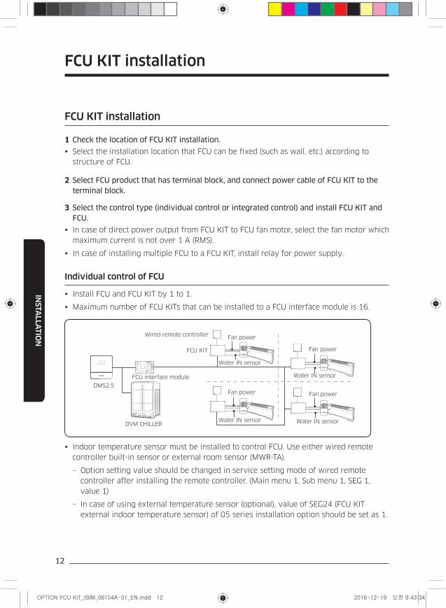
Individual control of FCU
Install FCU and FCU KIT by 1 to 1.
Maximum number of FCU KITs that can be installed to a FCU interface module is 16.
CN4
CN3
RED
CN2
BLK
YELREDY-GRN
Fan power
Fan power
Fan power
Fan power
Water IN sensor
Water IN sensor Water IN sensor
Water IN sensor
DVM CHILLER
DMS2.5
FCU interface module
Wired remote controller
FCU KIT
Indoor temperature sensor must be installed to control FCU. Use either wired remote
controller built-in sensor or external room sensor (MWR-TA).
– Option setting value should be changed in service setting mode of wired remote
controller after installing the remote controller. (Main menu 1, Sub menu 1, SEG 1,
value 1)
– In case of using external temperature sensor (optional), value of SEG24 (FCU KIT
external indoor temperature sensor) of 05 series installation option should be set as 1.
13
INSTA
LLA
TIO
N
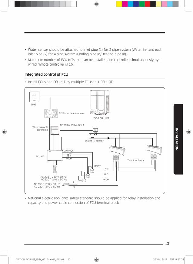
Water sensor should be attached to inlet pipe (1) for 2 pipe system (Water In), and each
inlet pipe (2) for 4 pipe system (Cooling pipe In/Heating pipe In).
Maximum number of FCU KITs that can be installed and controlled simultaneously by a
wired remote controller is 16.
Integrated control of FCU
Install FCUs and FCU KIT by multiple FCUs to 1 FCU KIT.
CN4
CN3
RED
CN2
BLK
YELREDY-GRN
DMS
M
Water IN sensor
LOWMIDHIGH
LOW
MID
HIGH
AC Water Valve 0.5 A
AC 208 ~ 230 V 60 Hz, AC 220 ~ 240 V 50 Hz
AC 208 ~ 230 V 60 Hz, AC 220 ~ 240 V 50 Hz
FCU interface module
Wired remote controller
DVM CHILLER
Relay
L
N
Terminal block
COMMON
FCU KIT
National electric appliance safety standard should be applied for relay installation and
capacity and power cable connection of FCU terminal block.
14
INSTA
LLA
TIO
N
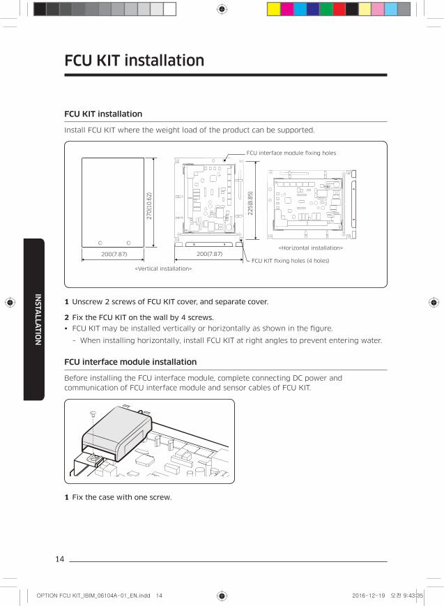
FCU KIT installation
Install FCU KIT where the weight load of the product can be supported.
200(7.87)
270(1
0.6
2)
225(8
.85)
200(7.87)
FCU interface module fixing holes
<Vertical installation>
<Horizontal installation>
FCU KIT fixing holes (4 holes)
1 Unscrew 2 screws of FCU KIT cover, and separate cover.
2 Fix the FCU KIT on the wall by 4 screws.
FCU KIT may be installed vertically or horizontally as shown in the figure.
– When installing horizontally, install FCU KIT at right angles to prevent entering water.
FCU interface module installation
Before installing the FCU interface module, complete connecting DC power and
communication of FCU interface module and sensor cables of FCU KIT.
1 Fix the case with one screw.
FCU KIT installation
15
INSTA
LLA
TIO
N
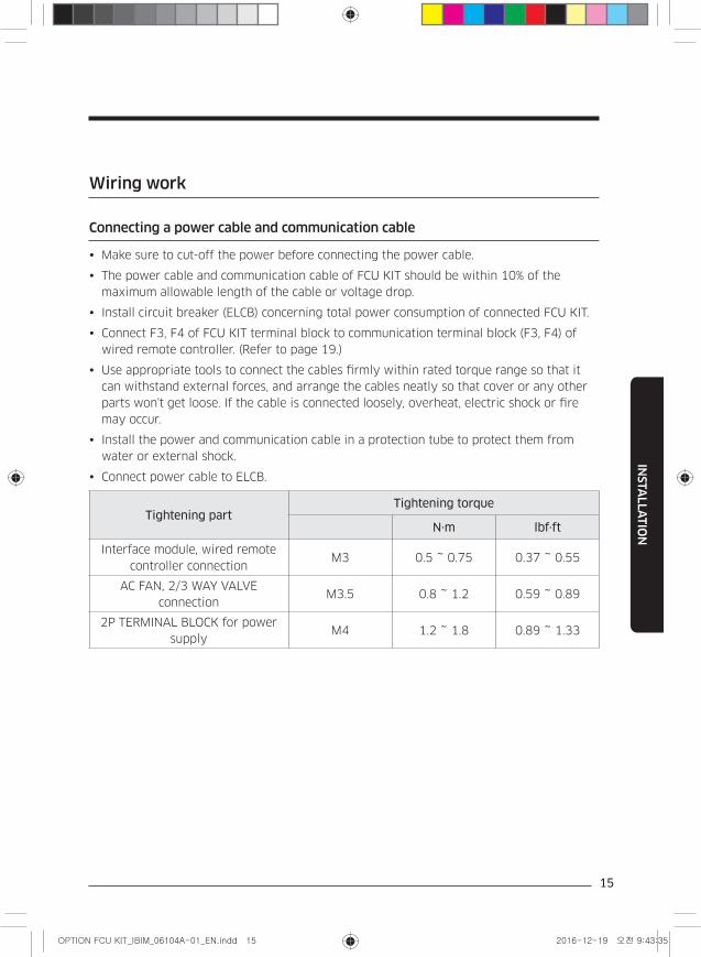
Wiring work
Connecting a power cable and communication cable
Make sure to cut-off the power before connecting the power cable.
The power cable and communication cable of FCU KIT should be within 10% of the
maximum allowable length of the cable or voltage drop.
Install circuit breaker (ELCB) concerning total power consumption of connected FCU KIT.
Connect F3, F4 of FCU KIT terminal block to communication terminal block (F3, F4) of
wired remote controller. (Refer to page 19.)
Use appropriate tools to connect the cables firmly within rated torque range so that it
can withstand external forces, and arrange the cables neatly so that cover or any other
parts won't get loose. If the cable is connected loosely, overheat, electric shock or fire
may occur.
Install the power and communication cable in a protection tube to protect them from
water or external shock.
Connect power cable to ELCB.
Tightening partTightening torque
N·m lbf·ft
Interface module, wired remote
controller connectionM3 0.5 ~ 0.75 0.37 ~ 0.55
AC FAN, 2/3 WAY VALVE
connectionM3.5 0.8 ~ 1.2 0.59 ~ 0.89
2P TERMINAL BLOCK for power
supplyM4 1.2 ~ 1.8 0.89 ~ 1.33
16
INSTA
LLA
TIO
N
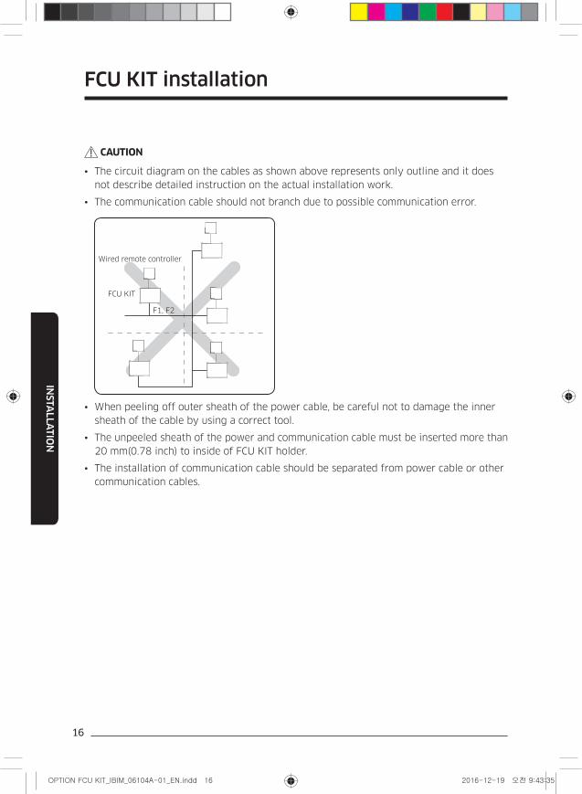
CAUTION
• The circuit diagram on the cables as shown above represents only outline and it does
not describe detailed instruction on the actual installation work.
• The communication cable should not branch due to possible communication error.
Wired remote controller
FCU KIT
F1, F2
• When peeling off outer sheath of the power cable, be careful not to damage the inner
sheath of the cable by using a correct tool.
• The unpeeled sheath of the power and communication cable must be inserted more than
20 mm(0.78 inch) to inside of FCU KIT holder.
• The installation of communication cable should be separated from power cable or other
communication cables.
FCU KIT installation
17
INSTA
LLA
TIO
N
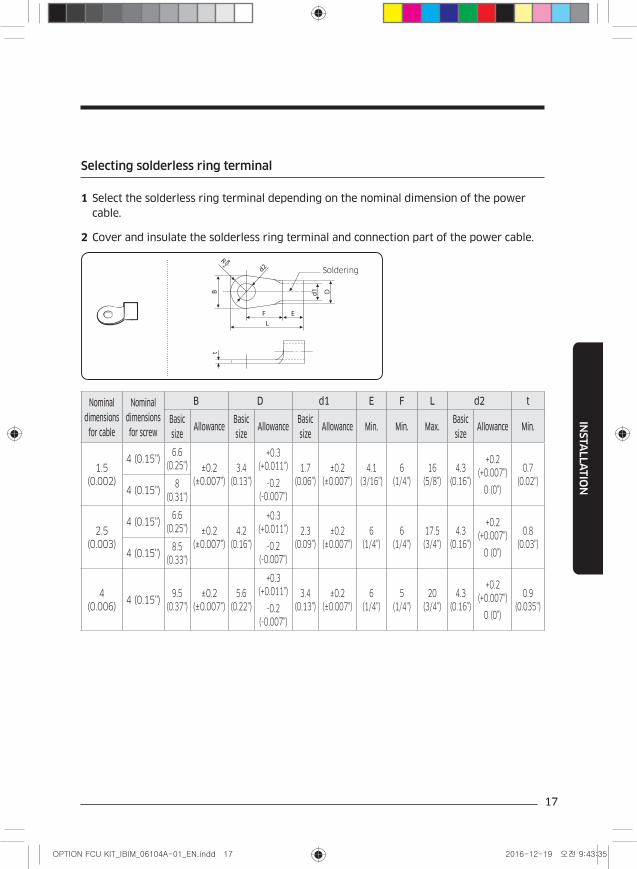
Selecting solderless ring terminal
1 Select the solderless ring terminal depending on the nominal dimension of the power cable.
2 Cover and insulate the solderless ring terminal and connection part of the power cable.
Soldering
Nominal dimensions
for cable
Nominal dimensions for screw
B D d1 E F L d2 t
Basic size
AllowanceBasic size
AllowanceBasic size
Allowance Min. Min. Max.Basic size
Allowance Min.
1.5
(0.002)
4 (0.15")6.6
(0.25") ±0.2
(±0.007")
3.4
(0.13")
+0.3
(+0.011")
-0.2
(-0.007")
1.7
(0.06")
±0.2
(±0.007")
4.1
(3/16")
6
(1/4")
16
(5/8")
4.3
(0.16")
+0.2
(+0.007")
0 (0")
0.7
(0.02")4 (0.15")
8
(0.31")
2.5
(0.003)
4 (0.15")6.6
(0.25") ±0.2
(±0.007")
4.2
(0.16")
+0.3
(+0.011")
-0.2
(-0.007")
2.3
(0.09")
±0.2
(±0.007")
6
(1/4")
6
(1/4")
17.5
(3/4")
4.3
(0.16")
+0.2
(+0.007")
0 (0")
0.8
(0.03")4 (0.15")
8.5
(0.33")
4
(0.006)4 (0.15")
9.5
(0.37")
±0.2
(±0.007")
5.6
(0.22")
+0.3
(+0.011")
-0.2
(-0.007")
3.4
(0.13")
±0.2
(±0.007")
6
(1/4")
5
(1/4")
20
(3/4")
4.3
(0.16")
+0.2
(+0.007")
0 (0")
0.9
(0.035")
18
INSTA
LLA
TIO
N
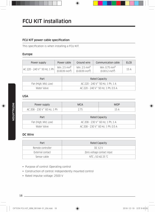
FCU KIT power cable specification
This specification is when installing a FCU KIT.
Europe
Power supply Power cable Ground wire Communication cable ELCB
AC 220 - 240 V~ 50 Hz, 1 PhMin. 2.5 mm
2
(0.0039 inch2)
Min. 2.5 mm2
(0.0039 inch2)
Min. 0.75 mm2
(0.0012 inch2)
15 A
Part Rated Capacity
Fan (High, Mid, Low) AC 220 - 240 V~ 50 Hz, 1 Ph, 1 A
Water Valve AC 220 - 240 V~ 50 Hz, 1 Ph, 0.5 A
USA
Power supply MCA MOP
AC 208 - 230 V~ 60 Hz, 1 Ph 2.75 15 A
Part Rated Capacity
Fan (High, Mid, Low) AC 208 - 230 V~ 60 Hz, 1 Ph, 1 A
Water Valve AC 208 - 230 V~ 60 Hz, 1 Ph, 0.5 A
DC Wire
Part Rated Capacity
Remote controller DC 12 V
External contact Zero voltage contact input
Sensor cable NTC ./10 kΩ 25 °C
Purpose of control: Operating control
Construction of control: Independently mounted control
Rated impulse voltage: 2500 V
FCU KIT installation
19
INSTA
LLA
TIO
N
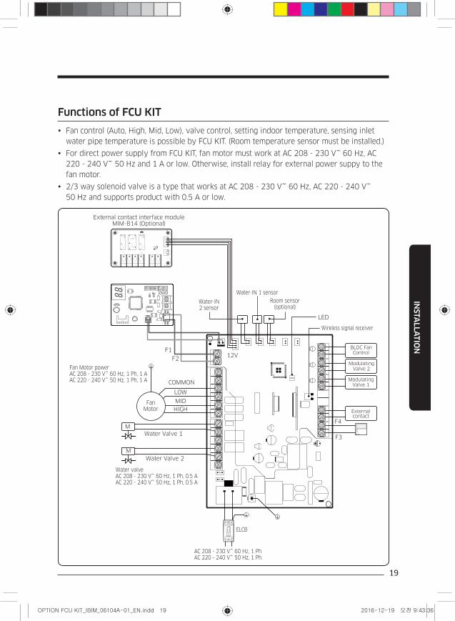
Functions of FCU KIT
Fan control (Auto, High, Mid, Low), valve control, setting indoor temperature, sensing inlet
water pipe temperature is possible by FCU KIT. (Room temperature sensor must be installed.)
For direct power supply from FCU KIT, fan motor must work at AC 208 - 230 V~ 60 Hz, AC
220 - 240 V~ 50 Hz and 1 A or low. Otherwise, install relay for external power suppy to the
fan motor.
2/3 way solenoid valve is a type that works at AC 208 - 230 V~ 60 Hz, AC 220 - 240 V~
50 Hz and supports product with 0.5 A or low.
CN4
CN3
RED
CN2
BLK
YELREDY-GRN
CN4
CN3
RED
CN2
BLK
YELREDY-GRN
Water Valve 1
Water Valve 2
12VF1
F2
Fan Motor
M
M
COMMON
Fan Motor power AC 208 - 230 V~ 60 Hz, 1 Ph, 1 A AC 220 - 240 V~ 50 Hz, 1 Ph, 1 A
External contact interface module MIM-B14 (Optional)
F4
F3
HIGH
MID
External contact
LOW
Water-IN 1 sensor
Water-IN 2 sensor
Room sensor (optional)
LED
Wireless signal receiver
Modulating Valve 1
Modulating Valve 2
BLDC Fan Control
ELCB
AC 208 - 230 V~ 60 Hz, 1 Ph AC 220 - 240 V~ 50 Hz, 1 Ph
Water valve AC 208 - 230 V~ 60 Hz, 1 Ph, 0.5 A AC 220 - 240 V~ 50 Hz, 1 Ph, 0.5 A
20
INSTA
LLA
TIO
N
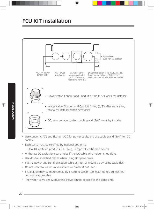
Power cable: Conduit and Conduit fitting (1/2") work by installer
Water valve: Conduit and Conduit fitting (1/2") after separating
screw by installer when necessary
DC, zero voltage contact: cable gland (3/4") work by installer
DC Communication cable (F1, F2, R1, R2), Room sensor (optional), Water sensor, Wired remote controller, External contact
AC, water valve power output cable (BLDC Fan Control,
Modulating Valve 1,2)
AC, FAN power output cable
AC, Power input cable
Spare holes (Use for DC cables)
Use conduit (1/2") and fitting (1/2") for power cable, and use cable gland (3/4") for DC
cables.
Each parts must be certified by national authority.
– USA: UL certified products (UL514B), Europe: CE certified products
Withdraw DC cables by spare holes if the DC cable wire holder is too tight.
Use double-sheathed cables when using DC spare holes.
Fix the power and communication cable at internal mount tie by using cable ties.
Do not unscrew water valve cable wire holder if not used.
Installation may be more simple by inserting sensor connector before connecting
communication cable.
The Water Valve and Modulating Valve cannot be used at the same time.
FCU KIT installation
21
INSTA
LLA
TIO
N
WARNING
Be sure to use the conduits and conduit fittings when extracting the wires for safety.
NOTE
• Arrange communication cables (F1, F2, R1, R2) to the opposite way of power cable.
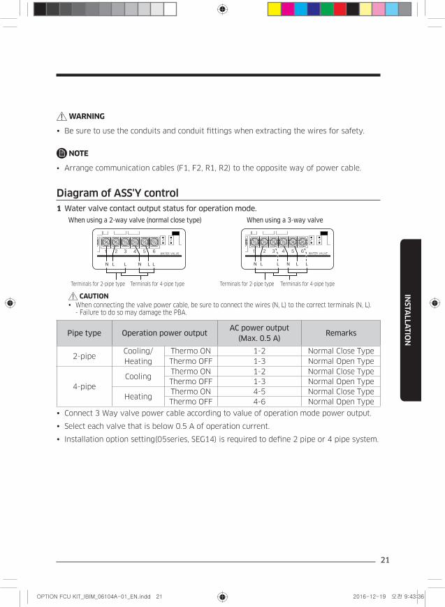
Diagram of ASS'Y control
1 Water valve contact output status for operation mode.
Pipe type Operation power outputAC power output
(Max. 0.5 A)Remarks
2-pipeCooling/
Heating
Thermo ON 1-2 Normal Close Type
Thermo OFF 1-3 Normal Open Type
4-pipe
CoolingThermo ON 1-2 Normal Close Type
Thermo OFF 1-3 Normal Open Type
HeatingThermo ON 4-5 Normal Close Type
Thermo OFF 4-6 Normal Open Type
Connect 3 Way valve power cable according to value of operation mode power output.
Select each valve that is below 0.5 A of operation current.
Installation option setting(05series, SEG14) is required to define 2 pipe or 4 pipe system.
CAUTIONWhen connecting the valve power cable, be sure to connect the wires (N, L) to the correct terminals (N, L). - Failure to do so may damage the PBA.
N NL L LL
When using a 2-way valve (normal close type) When using a 3-way valve
N NL L LL
Terminals for 2-pipe type Terminals for 4-pipe type Terminals for 2-pipe type Terminals for 4-pipe type
22
INSTA
LLA
TIO
N
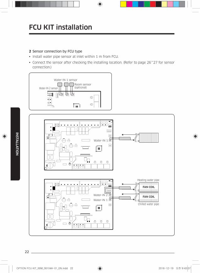
2 Sensor connection by FCU type
Install water pipe sensor at inlet within 1 m from FCU.
Connect the sensor after checking the installing location. (Refer to page 26~27 for sensor
connection.)
Water-IN 2 sensor
Water-IN 1 sensor
Room sensor (optional)
Water-IN 1
Heating water pipe
Chilled water pipe
FAN COIL
FAN COILWater-IN 2
Water-IN 1
FCU KIT installation
23
INSTA
LLA
TIO
N
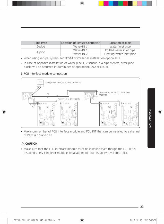
Pipe type Location of Sensor Connector Location of pipe2-pipe Water-IN 1 Water inlet pipe
4-pipeWater-IN 1 Chilled water inlet pipe
Water-IN 2 Heating water inlet pipe
When using 4-pipe system, set SEG14 of 05 series installation option as 1.
In case of opposite installation of water pipe 1, 2 sensor in 4 pipe system, error(pipe
block) will be occurred in 30minutes of operation(E992 or E993).
3 FCU interface module connection
CN4
CN3
RED
CN2
BLK
YELREDY-GRN
CN4
CN3
RED
CN2
BLK
YELREDY-GRN
V1
V2F1
F2
DMS(2.5 or later)/BACnet/LonWorks
Connect up to 16 FCU KITs
Connect up to 16 FCU interface modulesR1
R2
Maximum number of FCU interface module and FCU KIT that can be installed to a channel
of DMS is 16 and 128.
CAUTION
Make sure that the FCU interface module must be installed even though the FCU kit is
installed solely (single or multiple installation) without its upper level controller.
24
INSTA
LLA
TIO
N
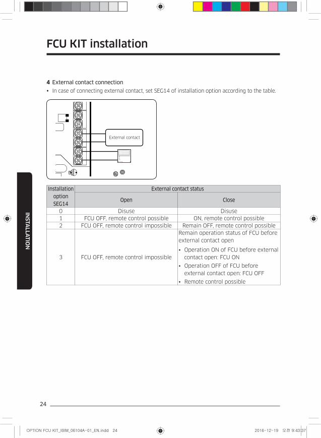
4 External contact connection
In case of connecting external contact, set SEG14 of installation option according to the table.
External contact
Installation option SEG14
External contact status
Open Close
0 Disuse Disuse
1 FCU OFF, remote control possible ON, remote control possible
2 FCU OFF, remote control impossible Remain OFF, remote control possible
3 FCU OFF, remote control impossible
Remain operation status of FCU before
external contact open
• Operation ON of FCU before external
contact open: FCU ON
• Operation OFF of FCU before
external contact open: FCU OFF
• Remote control possible
FCU KIT installation
25
INSTA
LLA
TIO
N
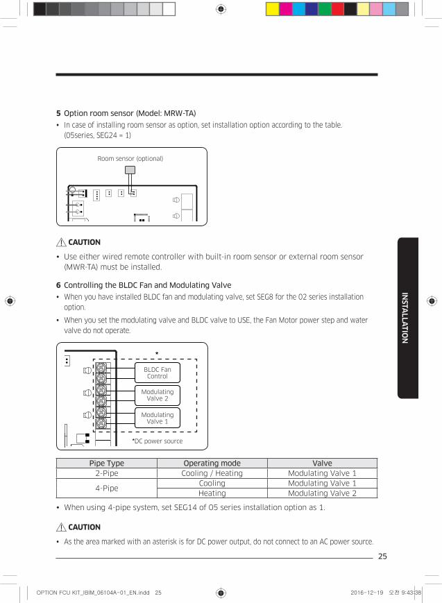
5 Option room sensor (Model: MRW-TA)
In case of installing room sensor as option, set installation option according to the table.
(05series, SEG24 = 1)
Room sensor (optional)
CAUTION
Use either wired remote controller with built-in room sensor or external room sensor
(MWR-TA) must be installed.
6 Controlling the BLDC Fan and Modulating Valve
When you have installed BLDC fan and modulating valve, set SEG8 for the 02 series installation
option.
When you set the modulating valve and BLDC valve to USE, the Fan Motor power step and water
valve do not operate.
BLDC Fan Control
*
Modulating Valve 2
Modulating Valve 1
*DC power source
Pipe Type Operating mode Valve2-Pipe Cooling / Heating Modulating Valve 1
4-PipeCooling Modulating Valve 1
Heating Modulating Valve 2
When using 4-pipe system, set SEG14 of 05 series installation option as 1.
CAUTION
As the area marked with an asterisk is for DC power output, do not connect to an AC power source.
26
INSTA
LLA
TIO
N
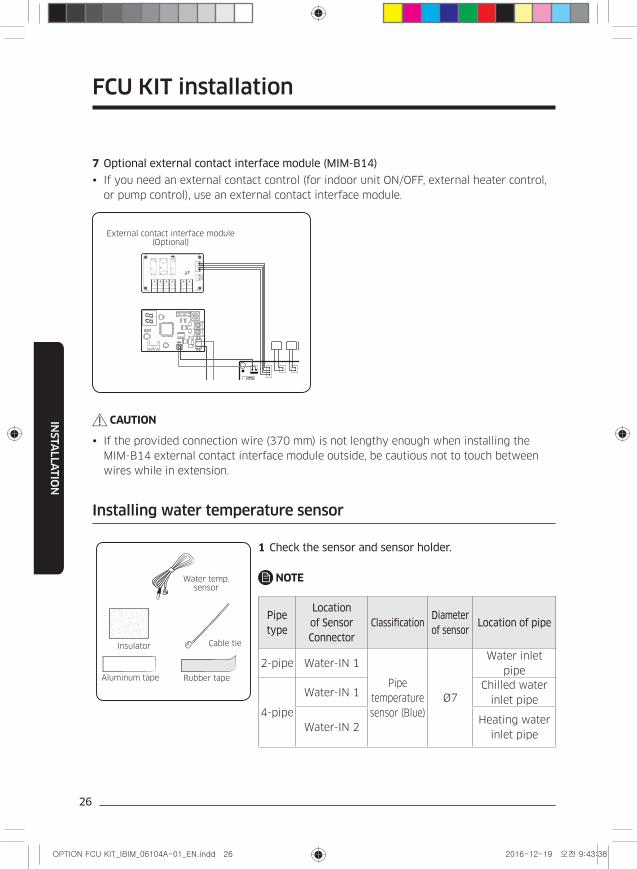
7 Optional external contact interface module (MIM-B14)
If you need an external contact control (for indoor unit ON/OFF, external heater control,
or pump control), use an external contact interface module.
CN4
CN3
RED
CN2
BLK
YELREDY-GRN
CN4
CN3
RED
CN2
BLK
YELREDY-GRN
External contact interface module (Optional)
CAUTION
If the provided connection wire (370 mm) is not lengthy enough when installing the
MIM-B14 external contact interface module outside, be cautious not to touch between
wires while in extension.
Installing water temperature sensor
Insulator
Aluminum tape Rubber tape
Cable tie
Water temp. sensor
1 Check the sensor and sensor holder.
NOTE
Pipe type
Location of Sensor Connector
ClassificationDiameter of sensor
Location of pipe
2-pipe Water-IN 1
Pipe
temperature
sensor (Blue)
Ø7
Water inlet
pipe
4-pipe
Water-IN 1Chilled water
inlet pipe
Water-IN 2Heating water
inlet pipe
FCU KIT installation
27
INSTA
LLA
TIO
N
Sensor
Pipe
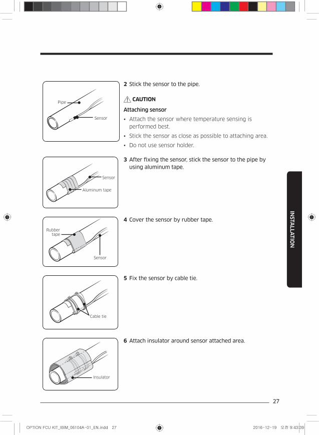
2 Stick the sensor to the pipe.
CAUTION
Attaching sensor
• Attach the sensor where temperature sensing is
performed best.
• Stick the sensor as close as possible to attaching area.
• Do not use sensor holder.
Sensor
Aluminum tape
3 After fixing the sensor, stick the sensor to the pipe by using aluminum tape.
Rubber tape
Sensor
4 Cover the sensor by rubber tape.
Cable tie
5 Fix the sensor by cable tie.
Insulator
6 Attach insulator around sensor attached area.
28
SE
TT
ING
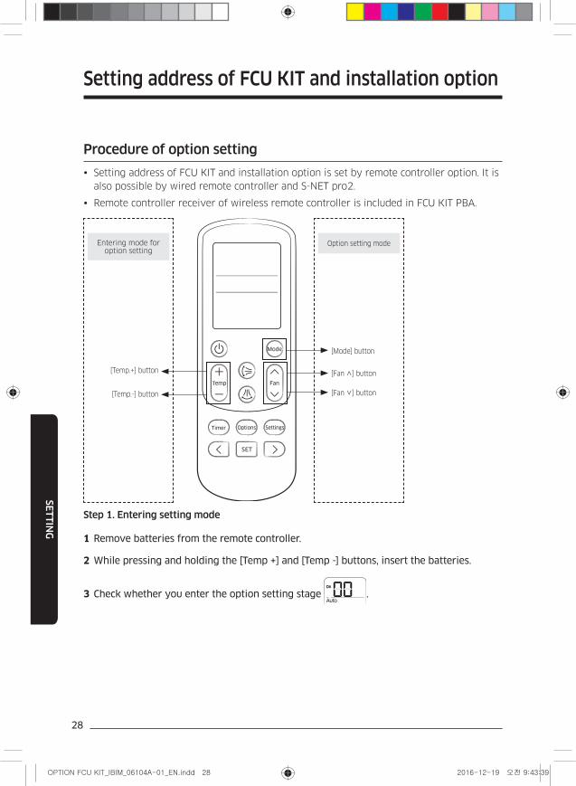
Procedure of option setting
Setting address of FCU KIT and installation option is set by remote controller option. It is
also possible by wired remote controller and S-NET pro2.
Remote controller receiver of wireless remote controller is included in FCU KIT PBA.
[Temp.+] button [Fan ∧] button
[Mode] button
[Temp.-] button [Fan ∨] button
Entering mode for option setting
Option setting mode
Step 1. Entering setting mode
1 Remove batteries from the remote controller.
2 While pressing and holding the [Temp +] and [Temp -] buttons, insert the batteries.
3 Check whether you enter the option setting stage .
Setting address of FCU KIT and installation option
29
SE
TT
ING
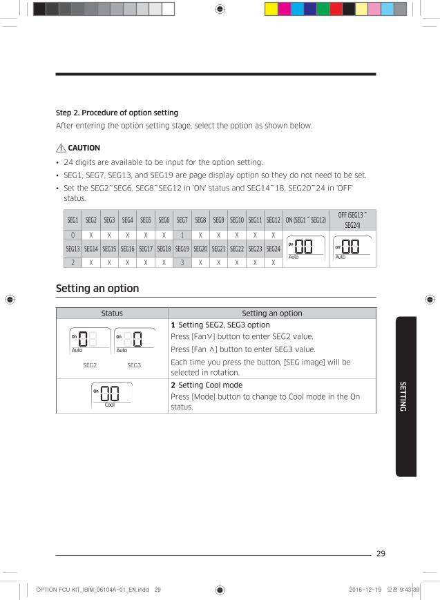
Step 2. Procedure of option setting
After entering the option setting stage, select the option as shown below.
CAUTION
• 24 digits are available to be input for the option setting.
• SEG1, SEG7, SEG13, and SEG19 are page display option so they do not need to be set.
• Set the SEG2~SEG6, SEG8~SEG12 in 'ON' status and SEG14~18, SEG20~24 in 'OFF'
status.
SEG1 SEG2 SEG3 SEG4 SEG5 SEG6 SEG7 SEG8 SEG9 SEG10 SEG11 SEG12 ON (SEG1 ~ SEG12)OFF (SEG13 ~
SEG24)0 X X X X X 1 X X X X X
SEG13 SEG14 SEG15 SEG16 SEG17 SEG18 SEG19 SEG20 SEG21 SEG22 SEG23 SEG24
2 X X X X X 3 X X X X X
Setting an option
Status Setting an option
SEG2 SEG3
1 Setting SEG2, SEG3 option
Press [Fan∨] button to enter SEG2 value.
Press [Fan ∧] button to enter SEG3 value.
Each time you press the button, [SEG image] will be
selected in rotation.
2 Setting Cool mode
Press [Mode] button to change to Cool mode in the On
status.
30
SE
TT
ING
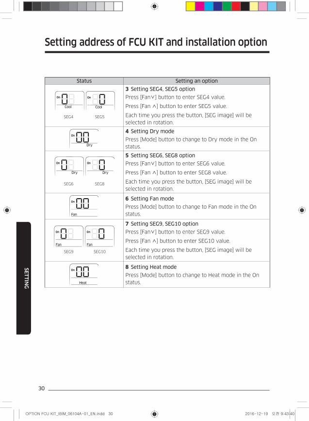
Status Setting an option
SEG4 SEG5
3 Setting SEG4, SEG5 option
Press [Fan∨] button to enter SEG4 value.
Press [Fan ∧] button to enter SEG5 value.
Each time you press the button, [SEG image] will be
selected in rotation.
4 Setting Dry mode
Press [Mode] button to change to Dry mode in the On
status.
SEG6 SEG8
5 Setting SEG6, SEG8 option
Press [Fan∨] button to enter SEG6 value.
Press [Fan ∧] button to enter SEG8 value.
Each time you press the button, [SEG image] will be
selected in rotation.
6 Setting Fan mode
Press [Mode] button to change to Fan mode in the On
status.
SEG9 SEG10
7 Setting SEG9, SEG10 option
Press [Fan∨] button to enter SEG9 value.
Press [Fan ∧] button to enter SEG10 value.
Each time you press the button, [SEG image] will be
selected in rotation.
8 Setting Heat mode
Press [Mode] button to change to Heat mode in the On
status.
Setting address of FCU KIT and installation option
31
SE
TT
ING
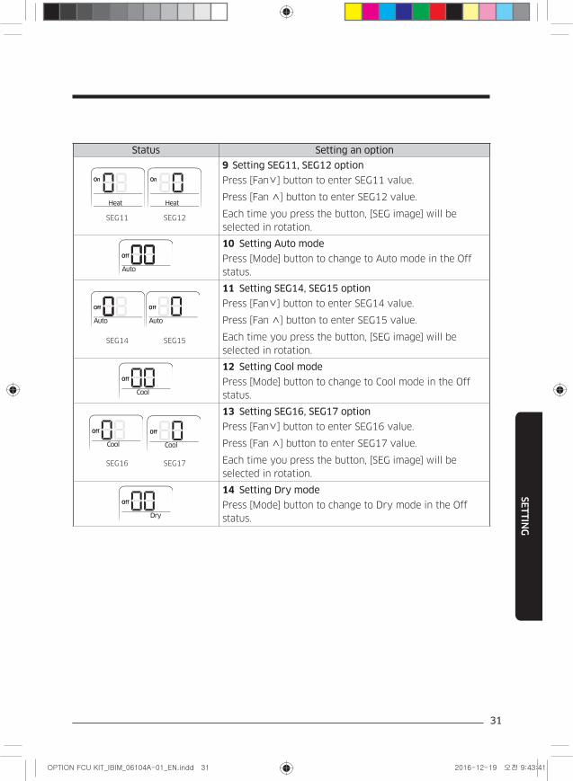
Status Setting an option
SEG11 SEG12
9 Setting SEG11, SEG12 option
Press [Fan∨] button to enter SEG11 value.
Press [Fan ∧] button to enter SEG12 value.
Each time you press the button, [SEG image] will be
selected in rotation.
10 Setting Auto mode
Press [Mode] button to change to Auto mode in the Off
status.
SEG14 SEG15
11 Setting SEG14, SEG15 option
Press [Fan∨] button to enter SEG14 value.
Press [Fan ∧] button to enter SEG15 value.
Each time you press the button, [SEG image] will be
selected in rotation.
12 Setting Cool mode
Press [Mode] button to change to Cool mode in the Off
status.
SEG16 SEG17
13 Setting SEG16, SEG17 option
Press [Fan∨] button to enter SEG16 value.
Press [Fan ∧] button to enter SEG17 value.
Each time you press the button, [SEG image] will be
selected in rotation.
14 Setting Dry mode
Press [Mode] button to change to Dry mode in the Off
status.
32
SE
TT
ING
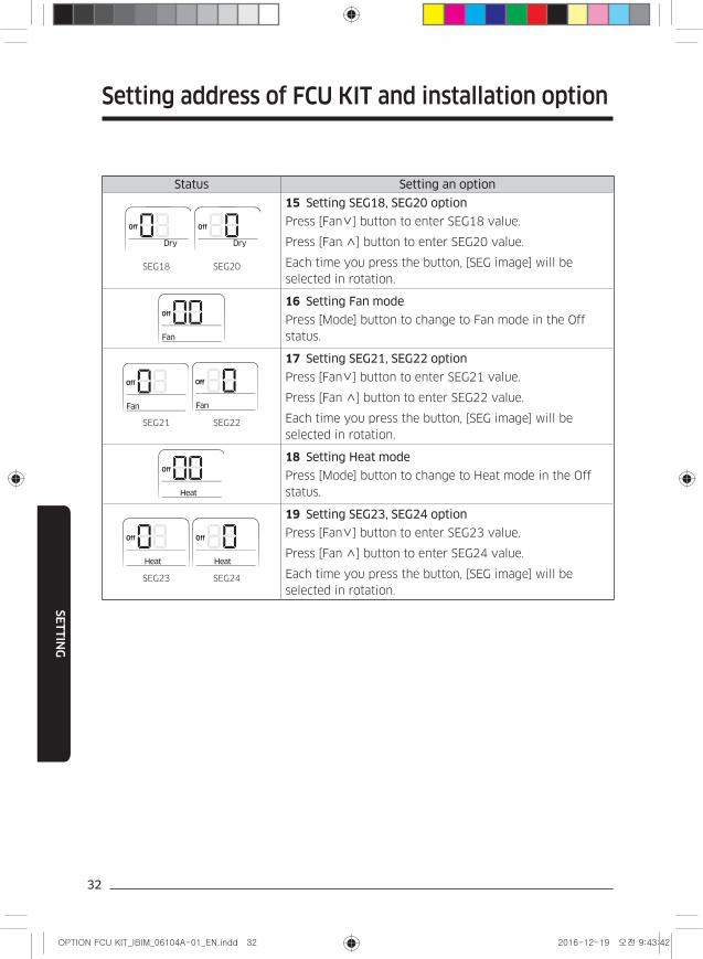
Status Setting an option
SEG18 SEG20
15 Setting SEG18, SEG20 option
Press [Fan∨] button to enter SEG18 value.
Press [Fan ∧] button to enter SEG20 value.
Each time you press the button, [SEG image] will be
selected in rotation.
16 Setting Fan mode
Press [Mode] button to change to Fan mode in the Off
status.
SEG21 SEG22
17 Setting SEG21, SEG22 option
Press [Fan∨] button to enter SEG21 value.
Press [Fan ∧] button to enter SEG22 value.
Each time you press the button, [SEG image] will be
selected in rotation.
18 Setting Heat mode
Press [Mode] button to change to Heat mode in the Off
status.
SEG23 SEG24
19 Setting SEG23, SEG24 option
Press [Fan∨] button to enter SEG23 value.
Press [Fan ∧] button to enter SEG24 value.
Each time you press the button, [SEG image] will be
selected in rotation.
Setting address of FCU KIT and installation option
33
SE
TT
ING
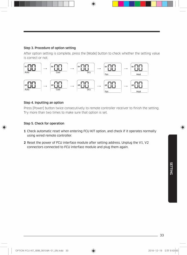
Step 3. Procedure of option setting
After option setting is complete, press the [Mode] button to check whether the setting value
is correct or not.
→ → → →
→ → → →
Step 4. Inputting an option
Press [Power] button twice consecutively to remote controller receiver to finish the setting.
Try more than two times to make sure that option is set.
Step 5. Check for operation
1 Check automatic reset when entering FCU KIT option, and check if it operates normally using wired remote controller.
2 Reset the power of FCU interface module after setting address. Unplug the V1, V2 connectors connected to FCU interface module and plug them again.
34
SE
TT
ING
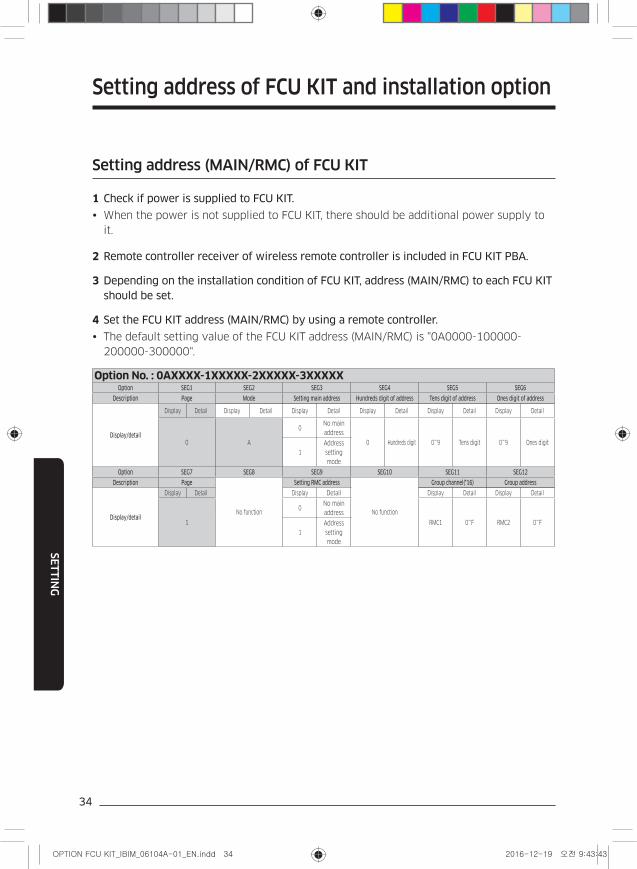
Setting address (MAIN/RMC) of FCU KIT
1 Check if power is supplied to FCU KIT.
When the power is not supplied to FCU KIT, there should be additional power supply to
it.
2 Remote controller receiver of wireless remote controller is included in FCU KIT PBA.
3 Depending on the installation condition of FCU KIT, address (MAIN/RMC) to each FCU KIT should be set.
4 Set the FCU KIT address (MAIN/RMC) by using a remote controller.
The default setting value of the FCU KIT address (MAIN/RMC) is "0A0000-100000-
200000-300000".
Option No. : 0AXXXX-1XXXXX-2XXXXX-3XXXXXOption SEG1 SEG2 SEG3 SEG4 SEG5 SEG6
Description Page Mode Setting main address Hundreds digit of address Tens digit of address Ones digit of address
Display/detail
Display Detail Display Detail Display Detail Display Detail Display Detail Display Detail
0 A
0No main
address
0 Hundreds digit 0~9 Tens digit 0~9 Ones digit
1
Address
setting
mode
Option SEG7 SEG8 SEG9 SEG10 SEG11 SEG12
Description Page
No function
Setting RMC address
No function
Group channel(*16) Group address
Display/detail
Display Detail Display Detail Display Detail Display Detail
1
0No main
address
RMC1 0~F RMC2 0~F
1
Address
setting
mode
Setting address of FCU KIT and installation option
35
SE
TT
ING
CAUTION
• Main address (SEG5 ~ SEG6) can be set in range of 0 ~ 47.
• When using automatic address setting, FCU interface module automatically assigns
FCU KIT address between 00 ~ 15.
• If you set the SEG 3 as 0, the FCU KIT will maintain the existing main address even if
you input the option value of SEG5 ~ SEG6.
• If you set the SEG9 as 0, the FCU KIT will maintain existing RMC address even if you
input the option value of SEG11 ~ SEG12.
Setting FCU KIT installation option
1 Check if power is supplied to FCU KIT.
When the power is not supplied to FCU KIT, there should be additional power supply to
it.
2 Remote controller receiver of wireless remote controller is included in FCU KIT PBA.
3 Depending on the installation condition of FCU KIT, installation option to each FCU KIT should be set.
4 Set the FCU KIT installation option by using a remote controller.
The default setting value of the FCU KIT installation option is "020010-100000-200000-
300000".
36
SE
TT
ING
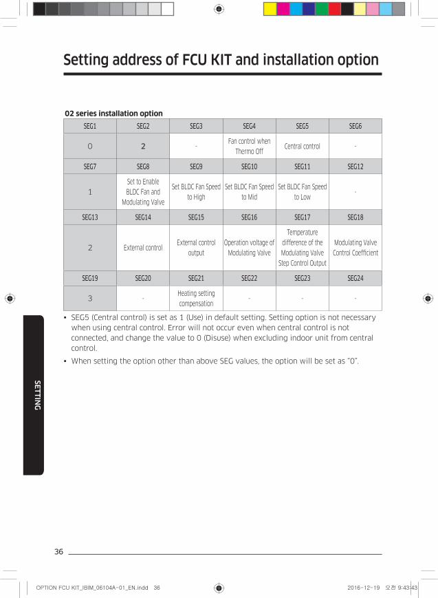
02 series installation option
SEG1 SEG2 SEG3 SEG4 SEG5 SEG6
0 2 -Fan control when
Thermo OffCentral control -
SEG7 SEG8 SEG9 SEG10 SEG11 SEG12
1
Set to Enable
BLDC Fan and
Modulating Valve
Set BLDC Fan Speed
to High
Set BLDC Fan Speed
to Mid
Set BLDC Fan Speed
to Low-
SEG13 SEG14 SEG15 SEG16 SEG17 SEG18
2 External controlExternal control
output
Operation voltage of
Modulating Valve
Temperature
difference of the
Modulating Valve
Step Control Output
Modulating Valve
Control Coefficient
SEG19 SEG20 SEG21 SEG22 SEG23 SEG24
3 -Heating setting
compensation- - -
SEG5 (Central control) is set as 1 (Use) in default setting. Setting option is not necessary
when using central control. Error will not occur even when central control is not
connected, and change the value to 0 (Disuse) when excluding indoor unit from central
control.
When setting the option other than above SEG values, the option will be set as “0”.
Setting address of FCU KIT and installation option
37
SE
TT
ING
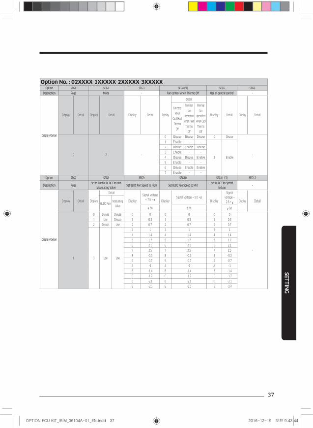
Option No. : 02XXXX-1XXXXX-2XXXXX-3XXXXXOption SEG1 SEG2 SEG3 SEG4 (*1) SEG5 SEG6
Description Page Mode - Fan control when Thermo Off Use of central control -
Display/detail
Display Detail Display Detail Display Detail Display
Detail
Display Detail Display Detail
Fan stop
when
Cool/Heat
Thermo
Off
Minimal
fan
operation
when Heat
Thermo
Off
Minimal
fan
operation
when Cool
Thermo
Off
0 2 -
0 Disuse Disuse Disuse 0 Disuse
-
1 Enable - -
1 Enable
2 Disuse Enable Disuse
3 Enable - -
4 Disuse Disuse Enable
5 Enable - -
6 Disuse Enable Enable
7 Enable - -
Option SEG7 SEG8 SEG9 SEG10 SEG11 (*2) SEG12
Description PageSet to Enable BLDC Fan and
Modulating ValveSet BLDC Fan Speed to High Set BLDC Fan Speed to Mid
Set BLDC Fan Speed to Low
-
Display/detail
Display Detail Display
Detail
Display
Signal voltage
= 7.5 + α DisplaySignal voltage = 5.0 + β
Display
Signal
voltage =
2.5 + γ Display DetailBLDC Fan
Modulating
Valveα (V) β (V) γ (V)
0 Disuse Disuse 0 0 0 0 0 0
-
1 Use Disuse 1 0.3 1 0.3 1 0.3
2 Disuse Use 2 0.7 2 0.7 2 0.7
1 3 Use Use
3 1 3 1 3 1
4 1.4 4 1.4 4 1.4
5 1.7 5 1.7 5 1.7
6 2.1 6 2.1 6 2.1
7 2.5 7 2.5 7 2.5
8 -0.3 8 -0.3 8 -0.3
9 -0.7 9 -0.7 9 -0.7
A -1 A -1 A -1
B -1.4 B -1.4 B -1.4
C -1.7 C -1.7 C -1.7
D -2.1 D -2.1 D -2.1
E -2.5 E -2.5 E -2.4
38
SE
TT
ING
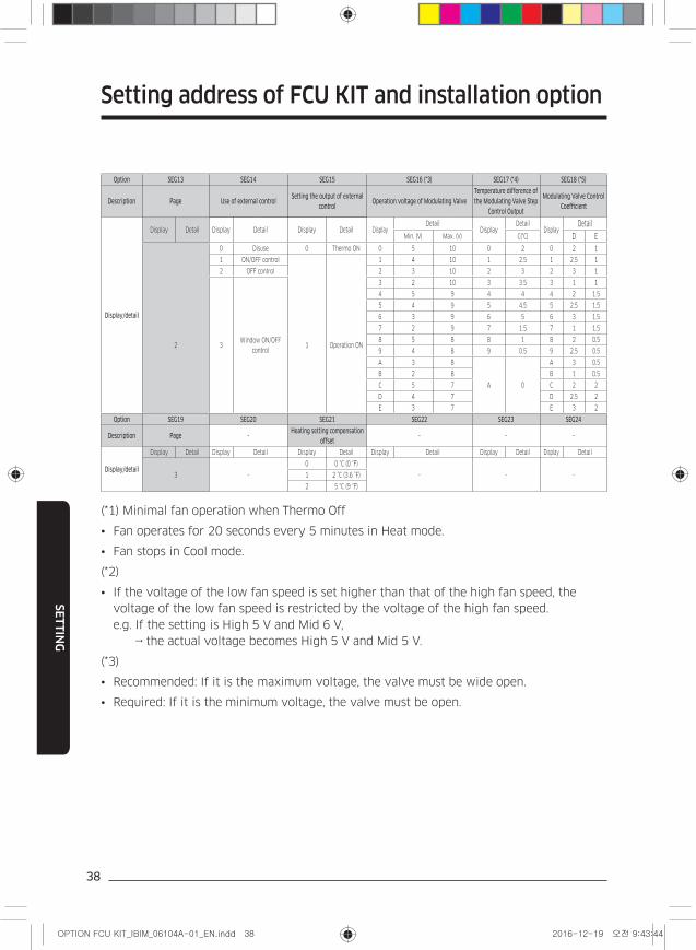
Option SEG13 SEG14 SEG15 SEG16 (*3) SEG17 (*4) SEG18 (*5)
Description Page Use of external controlSetting the output of external
controlOperation voltage of Modulating Valve
Temperature difference of the Modulating Valve Step
Control Output
Modulating Valve Control Coefficient
Display/detail
Display Detail Display Detail Display Detail DisplayDetail
DisplayDetail
DisplayDetail
Min. (V) Max. (V) C(°C) D E
0 Disuse 0 Thermo ON 0 5 10 0 2 0 2 1
1 ON/OFF control 1 4 10 1 2.5 1 2.5 1
2 OFF control 2 3 10 2 3 2 3 1
2 3Window ON/OFF
control1 Operation ON
3 2 10 3 3.5 3 1 1
4 5 9 4 4 4 2 1.5
5 4 9 5 4.5 5 2.5 1.5
6 3 9 6 5 6 3 1.5
7 2 9 7 1.5 7 1 1.5
8 5 8 8 1 8 2 0.5
9 4 8 9 0.5 9 2.5 0.5
A 3 8
A 0
A 3 0.5
B 2 8 B 1 0.5
C 5 7 C 2 2
D 4 7 D 2.5 2
E 3 7 E 3 2
Option SEG19 SEG20 SEG21 SEG22 SEG23 SEG24
Description Page -Heating setting compensation
offset- - -
Display/detail
Display Detail Display Detail Display Detail Display Detail Display Detail Display Detail
3 -
0 0 °C (0 °F)
- - -1 2 °C (3.6 °F)
2 5 °C (9 °F)
(*1) Minimal fan operation when Thermo Off
• Fan operates for 20 seconds every 5 minutes in Heat mode.
• Fan stops in Cool mode.
(*2)
• If the voltage of the low fan speed is set higher than that of the high fan speed, the
voltage of the low fan speed is restricted by the voltage of the high fan speed.
e.g. If the setting is High 5 V and Mid 6 V,
→ the actual voltage becomes High 5 V and Mid 5 V.
(*3)
• Recommended: If it is the maximum voltage, the valve must be wide open.
• Required: If it is the minimum voltage, the valve must be open.
Setting address of FCU KIT and installation option
39
SE
TT
ING
(*4)
• [Cool mode]
– Err= Indoor temperature – Set temperature – C (°C)
– If the value of Err is higher than 2, the modulating valve becomes open. Otherwise, the valve
step is adjusted.
• [Heat mode]
– Err= Set temperature – Indoor temperature + f – C (°C)
❋ f = Heating compensation (correction) temperature (default : 2)
– If the value of Err is higher than 2, the modulating valve becomes open. Otherwise, the valve
step is adjusted.
(*5)
– Cycle: 1 minute
– ΔErr = Errn – Errn-1
– ΔV = D * ΔErr + E * Errn
– New DCV output = Current DCV output + ΔV
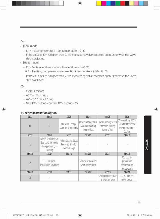
05 series installation optionSEG1 SEG2 SEG3 SEG4 SEG5 SEG6
0 5Use Auto Change
Over for 4-pipe only
(When setting SEG3)
Standard heating
temp. offset
(When setting SEG3)
Standard cooling
temp. offset
(When setting SEG3)
Standard for mode
change Heating →
Cooling
SEG7 SEG8 SEG9 SEG10 SEG11 SEG12
1
(When setting SEG3)
Standard for mode
change Cooling →
Heating
(When setting SEG3)
Required time for
mode change
- - -
SEG13 SEG14 SEG15 SEG16 SEG17 SEG18
2FCU KIT pipe
installation structure-
Valve open control
when Thermo Off-
FCU cool air
prevention
compensation
temperature
SEG19 SEG20 SEG21 SEG22 SEG23 SEG24
3 - - -Setting cool/heat air
prevention skip
FCU KIT external
room sensor
40
SE
TT
ING
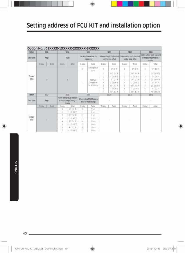
Option No. : 05XXXX-1XXXXX-2XXXXX-3XXXXXOption SEG1 SEG2 SEG3 SEG4 SEG5 SEG6
Description Page ModeUse Auto Change Over for
4-pipe only(When setting SEG3) Standard
heating temp. offset(When setting SEG3) Standard
cooling temp. offset
(When setting SEG3) Standard for mode change Heating →
Cooling
Display/detail
Display Detail Display Detail Display Detail Display Detail Display Detail Display Detail
0 5
0Follow product
option0 0 °C (0 °F) 0 0 °C (0 °F) 0 1 °C (1.8 °F)
1
Use Auto
Change Over
for 4-pipe only
1 0.5 °C (0.9 °F) 1 0.5 °C (0.9 °F) 1 1.5 °C (2.7 °F)
2 1 °C (1.8 °F) 2 1 °C (1.8 °F) 2 2 °C (3.6 °F)
3 1.5 °C (2.7 °F) 3 1.5 °C (2.7 °F) 3 2.5 °C (4.5 °F)
4 2 °C (3.6 °F) 4 2 °C (3.6 °F) 4 3 °C (5.4 °F)
5 2.5 °C (4.5 °F) 5 2.5 °C (4.5 °F) 5 3.5 °C (6.3 °F)
6 3 °C (5.4 °F) 6 3 °C (5.4 °F) 6 4 °C (7.2 °F)
7 3.5 °C (6.3 °F) 7 3.5 °C (6.3 °F) 7 4.5 °C (8.1 °F)
Option SEG7 SEG8 SEG9 SEG10 SEG11 SEG12
Description Page(When setting SEG3) Standard for mode change Cooling →
Heating
(When setting SEG3) Required time for mode change
- - -
Display/detail
Display Detail Display Detail Display Detail Display Detail Display Detail Display Detail
1
0 1 °C (1.8 °F) 0 5 min.
- - -
1 1.5 °C (2.7 °F) 1 7 min.
2 2 °C (3.6 °F) 2 9 min.
3 2.5 °C (4.5 °F) 3 11 min.
4 3 °C (5.4 °F) 4 13 min.
5 3.5 °C (6.3 °F) 5 15 min.
6 4 °C (7.2 °F) 6 20 min.
7 4.5 °C (8.1 °F) 7 30 min.
Setting address of FCU KIT and installation option
41
SE
TT
ING
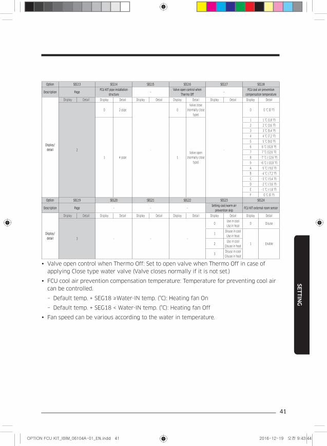
Option SEG13 SEG14 SEG15 SEG16 SEG17 SEG18
Description PageFCU KIT pipe installation
structure-
Valve open control when Thermo Off
-FCU cool air prevention
compensation temperature
Display/detail
Display Detail Display Detail Display Detail Display Detail Display Detail Display Detail
2
0 2-pipe
-
0
Valve close
(normally close
type)
-
0 0 °C (0 °F)
1 4-pipe 1
Valve open
(normally close
type)
1 1 °C (1,8 °F)
2 2 °C (3,6 °F)
3 3 °C (5,4 °F)
4 4 °C (7,2 °F)
5 5 °C (9,0 °F)
6 6 °C (10,8 °F)
7 7 °C (12,6 °F)
8 -7 °C (-12,6 °F)
9 -6 °C (-10,8 °F)
A -5 °C (-9,0 °F)
B -4 °C (-7,2 °F)
C -3 °C (-5,4 °F)
D -2 °C (-3,6 °F)
E -1 °C (-1,8 °F)
F 0 °C (0 °F)
Option SEG19 SEG20 SEG21 SEG22 SEG23 SEG24
Description Page - - -Setting cool/warm air
prevention skipFCU KIT external room sensor
Display/detail
Display Detail Display Detail Display Detail Display Detail Display Detail Display Detail
3 - - -
0Use in cool
Use in heat0 Disuse
1Disuse in cool
Use in heat
1 Enable2Use in cool
Disuse in heat
3Disuse in cool
Disuse in heat
Valve open control when Thermo Off: Set to open valve when Thermo Off in case of
applying Close type water valve (Valve closes normally if it is not set.)
FCU cool air prevention compensation temperature: Temperature for preventing cool air
can be controlled.
– Default temp. + SEG18 ≥Water-IN temp. (°C): Heating fan On
– Default temp. + SEG18 < Water-IN temp. (°C): Heating fan Off
Fan speed can be various according to the water in temperature.
42
SE
TT
ING
Warm air prevention in cooling
– Room < Water-IN temp. (°C) - 1 °C: Fan Off
– Room > Water-IN temp. (°C): Fan On
• In case of using external temperature sensor or minimal fan operation function,
external temperature sensor or wired remote controller should be connected. (Internal
temperature sensor option of wired remote controller should be set "Use" to use the
function. Refer to installation manual of wired remote controller.)
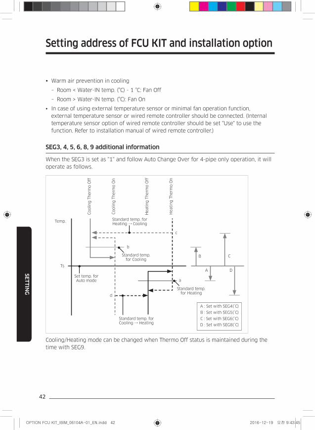
SEG3, 4, 5, 6, 8, 9 additional information
When the SEG3 is set as "1" and follow Auto Change Over for 4-pipe only operation, it will
operate as follows.
A : Set with SEG4(˚C)
B : Set with SEG5(˚C)
C : Set with SEG6(˚C)
D : Set with SEG8(˚C)
Cooling T
herm
o O
ff
Heati
ng T
herm
o O
ff
Cooling T
herm
o O
n
Heati
ng T
herm
o O
n
B C
DTs
A
c
a
Temp.
d
b
Standard temp. for Heating
Standard temp. for Cooling
Standard temp. for Heating → Cooling
Standard temp. for Cooling → Heating
Set temp. for Auto mode
Cooling/Heating mode can be changed when Thermo Off status is maintained during the
time with SEG9.
Setting address of FCU KIT and installation option
43
SE
TT
ING
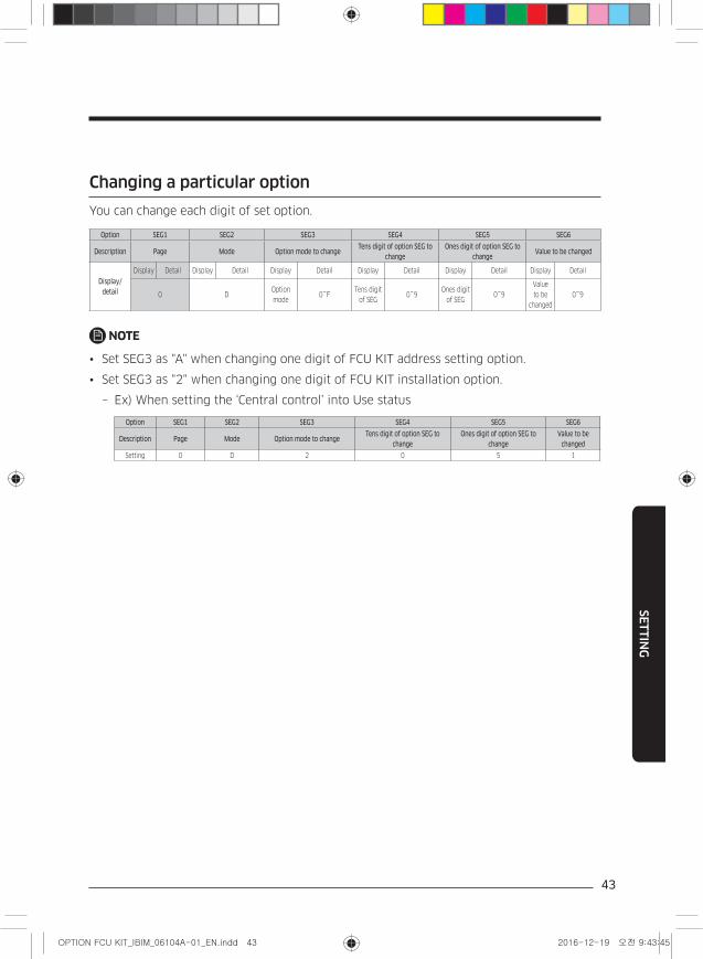
Changing a particular option
You can change each digit of set option.
Option SEG1 SEG2 SEG3 SEG4 SEG5 SEG6
Description Page Mode Option mode to changeTens digit of option SEG to
changeOnes digit of option SEG to
changeValue to be changed
Display/detail
Display Detail Display Detail Display Detail Display Detail Display Detail Display Detail
0 DOption
mode0~F
Tens digit
of SEG0~9
Ones digit
of SEG0~9
Value
to be
changed
0~9
NOTE
• Set SEG3 as "A" when changing one digit of FCU KIT address setting option.
• Set SEG3 as "2" when changing one digit of FCU KIT installation option.
– Ex) When setting the ‘Central control’ into Use status
Option SEG1 SEG2 SEG3 SEG4 SEG5 SEG6
Description Page Mode Option mode to changeTens digit of option SEG to
changeOnes digit of option SEG to
changeValue to be
changed
Setting 0 D 2 0 5 1
44
OT
HE
RS
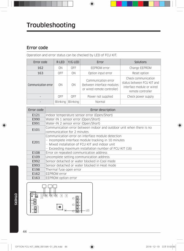
Error code
Operation and error status can be checked by LED of FCU KIT.
Error code R-LED Y/G-LED Error Solutions
162 ON OFF EEPROM error Change EEPROM
163 OFF ON Option input error Reset option
Communication error ON ON
Communication error
(between interface modules
or wired remote controller)
Check communication
status between FCU KIT and
interface module or wired
remote controller
- OFF OFF Power not supplied Check power supply
- Blinking Blinking Normal
Error code Error description
E121 Indoor temperature sensor error (Open/Short)
E990 Water-IN 1 sensor error (Open/Short)
E991 Water-IN 2 sensor error (Open/Short)
E101Communication error between indoor and outdoor unit when there is no
communication for 2 minutes
E201
Communication error on interface module detection
- Incomplete interface module tracking in 10 minutes
- Mixed installation of FCU KIT and indoor unit
- Exceeding maximum installation number of FCU KIT (16)
E108 Error on repeated communication address
E109 Uncomplete setting communication address
E992 Sensor detached or water blocked in Cool mode
E993 Sensor detached or water blocked in Heat mode
E198 Thermal fuse open error
E162 EEPROM error
E163 EEPROM option error
LED
Troubleshooting
OT
HE
RS
45
Checking FCU KIT installation
Check if FCU KIT is installed properly.
– Check if cables of FCU KIT are properly connected.
– Check if FCU KIT is installed vertically or horizontally.
– Install FCU KIT avoiding condensation area and water pipe line.
– Tighten wire holder to fix power and communication cable.
– Check if the locations of FCU KIT sensor and valve is appropriate.
– Check if the location of sensor is placed at inlet and the sensor is attached to the pipe.
Trial operation
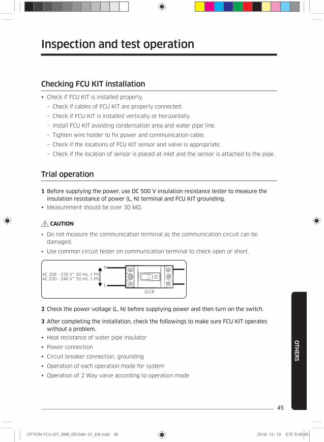
1 Before supplying the power, use DC 500 V insulation resistance tester to measure the insulation resistance of power (L, N) terminal and FCU KIT grounding.
Measurement should be over 30 MΩ.
CAUTION
• Do not measure the communication terminal as the communication circuit can be
damaged.
• Use common circuit tester on communication terminal to check open or short.
ELCB
N
L
AC 208 - 230 V~ 60 Hz, 1 Ph AC 220 - 240 V~ 50 Hz, 1 Ph
2 Check the power voltage (L, N) before supplying power and then turn on the switch.
3 After completing the installation, check the followings to make sure FCU KIT operates without a problem.
Heat resistance of water pipe insulator
Power connection
Circuit breaker connection, grounding
Operation of each operation mode for system
Operation of 2 Way valve according to operation mode
Inspection and test operation
46
OT
HE
RS
CAUTION
Solution for mixed operation prevention
• This function is to prevent DVM CHILLER and FCU (KIT) from operating in different
modes.
– Ex.) The situation that cool air comes out since DVM CHILLER is operating in Cool
mode and FCU is operating in Heat mode in 2-pipe system
– If Lock function is set on DMS2.5 or Touch centralized controller: Other operation
modes cannot be operated by FCU KIT if administrator selected Cool/Heat mode and
set Lock function on DMS2.5 or Touch centralized controller
– If Lock function is not set on DMS2.5 or Touch centralized controller: Refer for
maintenance that it detects water outlet temperature and stops fan after 10 minutes
if temperature is not appropriate, and error message will occur if the fan is stopped
for more than 30 minutes (E992, E993).
Inspection and test operation
OT
HE
RS
47
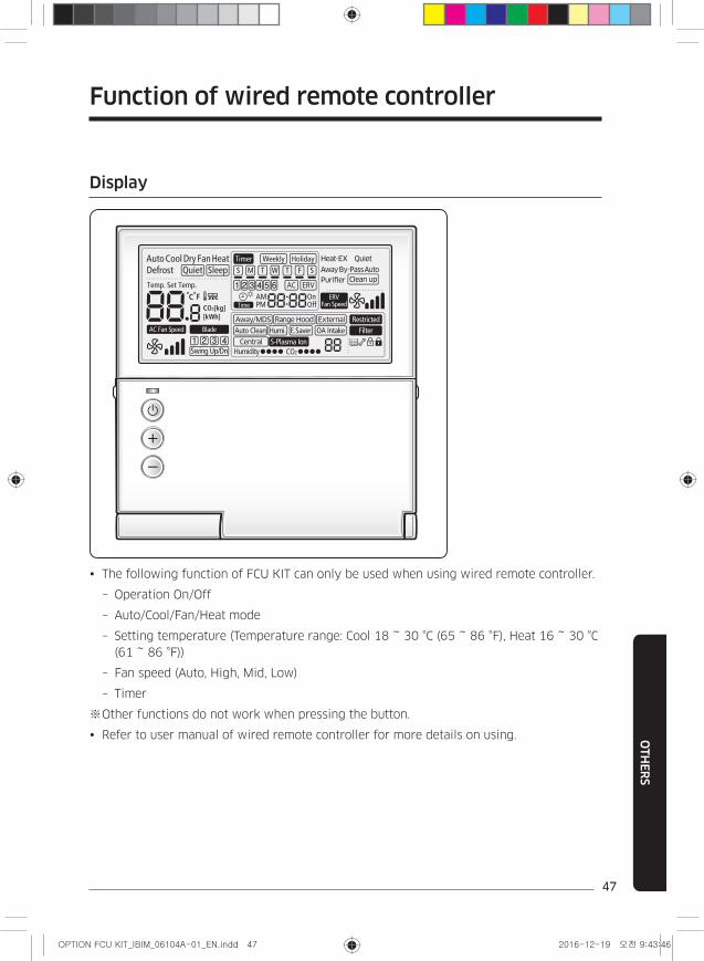
Display
The following function of FCU KIT can only be used when using wired remote controller.
– Operation On/Off
– Auto/Cool/Fan/Heat mode
– Setting temperature (Temperature range: Cool 18 ~ 30 °C (65 ~ 86 °F), Heat 16 ~ 30 °C
(61 ~ 86 °F))
– Fan speed (Auto, High, Mid, Low)
– Timer
※ Other functions do not work when pressing the button.
Refer to user manual of wired remote controller for more details on using.
Function of wired remote controller


![Contribution à la modélisation et la caractérisation de ... · Manille Philippines, [CI5], [CN3]. • (1988) Lors des marchés d’études CNET : Patrick JUNCAR [CN1], Bureau National](https://img.pdfslide.us/doc/110x75/5ede0d79ad6a402d66695242/contribution-la-modlisation-et-la-caractrisation-de-manille-philippines.jpg)