Embed Size (px)
Citation preview

DVAP Dongle Technical ReferenceRev. 1.01
1 Copyright @ 2010 Internet Labs Inc. Rev 1.01 2010-05-22

Table of Contents1 DVAP Dongle Description......................................................................................................................42 How It Works..........................................................................................................................................43 Choosing a Frequency.............................................................................................................................54 DVAP Operation.....................................................................................................................................6
4.1 DVAP USB Driver Installation........................................................................................................64.2 DVAPTool Installation and Setup...................................................................................................64.3 DVAP LED Indicators.....................................................................................................................6
5 Things to Avoid.......................................................................................................................................66 Technical Description..............................................................................................................................87 Specifications..........................................................................................................................................9
7.1 Receiver...........................................................................................................................................97.2 Transmitter.......................................................................................................................................97.3 USB Interface..................................................................................................................................97.4 RF Connection.................................................................................................................................97.5 Spectral Graphs.............................................................................................................................10
7.5.1 IF Filter Sweep......................................................................................................................107.5.2 Wide Band Plots.....................................................................................................................117.5.3 Narrow Band Plots.................................................................................................................11
7.6 Interface Protocol Specification....................................................................................................137.6.1 Message Block Format..........................................................................................................157.6.2 Set Control Item.....................................................................................................................177.6.3 Request Control Item.............................................................................................................177.6.4 Request Control Item Range..................................................................................................177.6.5 Response to Set or Request Current Control Item.................................................................177.6.6 Unsolicited Control Item.......................................................................................................177.6.7 Response to Request Control Item Range.............................................................................177.6.8 Data Item Messages...............................................................................................................187.6.9 The ACK and NAK Messages and Their Purpose.................................................................197.6.10DVAP Specific Control/Data Item Definitions.....................................................................207.6.11General DVAP Control Items...............................................................................................20
7.6.11.1 Target Name.................................................................................................................207.6.11.2 Target Serial Number...................................................................................................207.6.11.3 Interface Version..........................................................................................................217.6.11.4 Hardware/Firmware Versions.......................................................................................217.6.11.5 Status/Error Code.........................................................................................................21
7.6.12 DVAP Specific Control Items..............................................................................................227.6.12.1 Run State......................................................................................................................227.6.12.2 DVAP Modulation Type...............................................................................................227.6.12.3 DVAP Operation Mode...............................................................................................237.6.12.4 DVAP Squelch Threshold...........................................................................................237.6.12.5 DVAP Operational Status............................................................................................237.6.12.6 DVAP PTT State.........................................................................................................247.6.12.7 DVAP External T/R Control Mode.............................................................................25
2 Copyright @ 2010 Internet Labs Inc. Rev 1.01 2010-05-22

7.6.12.8 DVAP Manual LED Control.......................................................................................257.6.12.9 DVAP Receiver Frequency.........................................................................................267.6.12.10 DVAP Transmit Frequency........................................................................................267.6.12.11 DVAP Transmit and Receive Frequency...................................................................267.6.12.12 DVAP TX Frequency Limits Read Only....................................................................277.6.12.13 DVAP TX Power Setting............................................................................................277.6.12.14 DVAP Frequency Calibration....................................................................................287.6.12.15 DVAP Band Scan.......................................................................................................287.6.12.16 DVAP DTMF Message..............................................................................................29
7.6.13 DVAP WatchDog Keepalive Message.................................................................................297.6.14 DVAP Data Item Definitions...............................................................................................30
7.6.14.1 DVAP FM mode (Data Item 0)....................................................................................307.6.14.2 DVAP GMSK Mode DSTAR Header (Data Item 1)....................................................307.6.14.3 DVAP GMSK Mode DSTAR Header TX ACK message............................................317.6.14.4 DVAP GMSK Mode DSTAR Voice/Slow Data (Data Item 2)....................................31
3 Copyright @ 2010 Internet Labs Inc. Rev 1.01 2010-05-22

1 DVAP Dongle DescriptionThe Digital Voice Access Point(DVAP) Dongle is a short range 2 meter GMSK/FM
transceiver that connects to a PC using a USB port. This device makes possible the use of a D-STAR( Digital Smart Technologies for Amateur Radio ) capable 2 meter transceiver to communicate directly to the Internet D-STAR network through the DVAP and PC software.
A typical application would be where a user in not within range of a D-STAR repeater and would like to be able to use a hand held transceiver to access the D-STAR network around the house or local neighborhood within about a 100 meter radius.
2 How It WorksThe DVAP contains a small 144 -148 MHz GMSK/FM transceiver that communicates with
any DSTAR compatible radio. The DVAP sends and receives all the voice and data information back to the PC via a USB connection. The PC application”DVAPTool” connects to the D-STAR network over the users Internet connection and links to whatever reflector or repeater that was specified similar to the operation of the DVDongle.
The main difference between the DVAP Dongle and DVDongle is that the users hand held radio is used to control the linking and un-linking as well as for the audio instead of the PC sound card. This gives a more “normal” amateur radio experience since an actual radio is used as well as the flexibility of not being required to be seated at the PC.
4 Copyright @ 2010 Internet Labs Inc. Rev 1.01 2010-05-22
DVAP
2m D-STARTransceiver
PCInternetUSB
DVAP Dongle Operation

3 Choosing a FrequencyChoosing a frequency to operate on should be carefully considered before using the DVAP.The first thing to consider is to follow the band plan for your particular region. The ARRL
publishes a band plan document for the US that can be used to narrow your choices.http://www.arrl.org/FandES/field/regulations/bandplan.html Frequencies to avoid are those in the weak signal and satellite sections of the band and of
course all the local repeater input and output frequencies. Also avoid common FM calling frequencies such as 146.52 and Packet frequencies such as used for APRS.
The output power of the DVAP is very low( ~10mW) and the antenna is very low gain so the chance of it interfering is quite low since it can only be heard over a small area.
However, your hand held(or mobile) D-Star transceiver is quite capable of transmitting over much longer distances so it is important to operate it at as low a power setting as possible and avoid frequencies that may interfere with others. The added benefit of operating at lower power is that your battery life will be extended.
A frequency range to avoid is from around 147.4 MHz to 147.5 MHz. The DVAP has an internal spur at 147.456 MHz that mixes with the GMSK signal and produces spurious products within this range. Although they are not as strong as the main signal and the DVAP is low power to begin with, one may want to avoid this range unless it is the only one available. Below is a scan of the internal DVAP receiver without an antenna showing some internal spurs. One is at 145.0MHz and another one is at 147.454MHz so these are two areas to avoid.
On the receive side, since the DVAP most likely will be physically located very close to a PC and assorted digital devices, it is very likely that there will be all sorts of interference to the DVAP on various frequencies. One way to find a clean frequency is to put your hand held radio in FM mode and open up the squelch. Tune around the area of interest and listen for interfering signals which are indicated by either quieting of the noise or assorted squeals and buzzes characteristic of computer generated noise. Locating the DVAP as far away from your PC will also help. Another indication of interference is by looking at the RSSI (Receive Signal Strength Indication) that is displayed on DVAPTool. A normal reading without a signal should only be 1 to 3 bars.
5 Copyright @ 2010 Internet Labs Inc. Rev 1.01 2010-05-22

4 DVAP OperationOperation of the DVAP Dongle is automatic once it is setup. All control of it is through the
DVAPTool software or the remote D-STAR transceiver.
4.1 DVAP USB Driver InstallationOn a Windows machine PC, the USB driver should load automatically as it is a signed
driver included by Microsoft. The first time the DVAP is plugged into a USB port, the driver should load and the green LED on the DVAP should begin slowly pulsing.
4.2 DVAPTool Installation and SetupThe latest version of DVAPTool and installation instructions can be found here: http://opendstar.org/tools/
4.3 DVAP LED IndicatorsThere are four LED's on the DVAP to indicate various states of operation.
• The Blue LED indicates data transfer from the PC to the DVAP Dongle.
• The Yellow LED indicates a D-STAR packet error while transmitting.A periodic blip of this LED simply means a packet was missing or out of order. This is common and should not be an issue unless it is on most of the time.
• The Red LED indicates that the transmitter is on or an error state.The LED is on solid during transmit. If it is blinking then it indicates a hardware error condition such as PLL out of lock and the device will not transmit.
• The Green LED indicates operation and receive status.The slowly pulsing Green LED indicates that the DVAP is connected to the PC but is idle and not connected to the DVAPTool program and running.When running, the green LED indicates that the DVAP is receiving a signal from a D-STAR radio.
• The Red, Green, and Yellow LED's all flashing quickly together indicate a PLL hardware failure and the device will not transmit.
5 Things to AvoidAn external outdoor antenna can be used to extend the range somewhat. As an example
an outdoor vertical antenna here on a roof extended the range to around 1000m. Of course your range will depend on all the normal factors such as height, antenna gain, etc.
It may be tempting to try and extend the range of the DVAP even more by adding a power
6 Copyright @ 2010 Internet Labs Inc. Rev 1.01 2010-05-22

amplifier to it. This is NOT a good idea for several reasons. Primarily, the DVAP was NOT designed to produce as clean a signal that a full blown transceiver is required to produce. While the DVAP GMSK signal is quite pure, it does produce a higher phase noise floor due to the simple single chip transceiver design. What this means is that for low power, the noise floor is not an issue but if amplified, then it may interfere with adjacent frequencies.
On the receive side, the DVAP receiver is not as sensitive as a normal radio and also has less selectivity so would produce sub-par performance if one were to try and use it for long range operation or in a noisy urban environment.
The DVAP works quite well for its intended purpose as a short range radio transceiver but not as a high power “Hot Spot” transceiver for serving a wide area.
The DVAP frequency reference is not temperature compensated so will drift with temperature. It is calibrated at normal room temperatures and will be OK in the normal home/office environments however may drift several KHz if placed in extreme temperatures such as in a car in the hot sun or outside during the winter. If the DVAP is not communicating reliably it could be off frequency a bit. One way to adjust is to set the DVAPTool operating frequency up or down in 1000Hz steps until it works reliably. Do not adjust your hand held frequency as it can only tune in big 5KHz steps.
7 Copyright @ 2010 Internet Labs Inc. Rev 1.01 2010-05-22

6 Technical DescriptionThe heart of the DVAP Dongle is a low power transceiver chip made by Analog Devices
called the ADF7021-N. This device contains all the circuitry to form a GMSK transceiver including not only the RF generation and receiving, but also the modulation and demodulation of a 4800 bps GMSK signal such as used in the D-STAR system.
The DVAP can also use analog FM and has built in DTMF tone decoder functionality.The DVAP uses a small ARM7 microcomputer to provide the high level interface via a USB
link to the PC. A block diagram of the DVAP is shown below:
The DVAP uses an FTDI USB interface chip that makes the USB port look like a standard serial COM port operating at 230400 baud. Power and all communications to the PC is provided with this USB virtual serial port interface.
8 Copyright @ 2010 Internet Labs Inc. Rev 1.01 2010-05-22
AnalogDevices
ADF7021N
AtmelAT91SAM7S256
uC64K RAM
256K FLASH
FTDIFT232RL
USB 2.0Full Speed
PowerControl
VoltageReg
Sig-DeltaFilter
JTAGDebugPort
DVAP DongleBlock Diagram © 2009 Internet Labs
Activity
SPI Control
Status
230400 bpsUART Data
Data
SerialDAC
19.6608MHzXtalVCO
A/D
EEROM
144.0 – 148.0 MHz
BPFilter

7 SpecificationsPreliminary specifications of the DVAP Dongle and are subject to change.
7.1 ReceiverFrequency range: 144.0 to 148.0 MHz (144.0 to 146.0 in ITU Region 1)Frequency Stability: +/-50ppm -20C to +70CSensitivity: ~ -110 dBmSelectivity: ~13.5KHz 5th order Butterworth IF filterDemodulator: Correlator 2FSK demodulator for GMSK
Linear Discriminator for FM
7.2 TransmitterFrequency range: 144.0 to 148.0 MHz (144.0 to 146.0 in ITU Region 1)Frequency Stability: +/-50ppm -20C to +70CPower Out: Adjustable -12 dBm to +10 dBmModulation: 4800bps Gaussian shaped 2FSK +/-1200Hz MSK deviation
+/-5KHz analog FM deviation
7.3 USB InterfaceThe full speed USB interface is provided by an FTDI interface chip. Power for the DVAP is
also provided by this interface so no other connection is required. The connector is a mini-B type.
7.4 RF ConnectionThe RF connector is a normal polarity female SMA connector and is nominally a 50 Ohm
impedance connection.
9 Copyright @ 2010 Internet Labs Inc. Rev 1.01 2010-05-22

7.5 Spectral GraphsThe receiver IF filter shape and RF spectrum output of the DVAP transmitter is compared
to that of an ICOM IC-91AD in low power mode.
7.5.1 IF Filter SweepThis is a sweep of the DVAP IF filter when set to 9KHz instead of the normal 13.5KHz. The filters are slightly asymmetric.
10 Copyright @ 2010 Internet Labs Inc. Rev 1.01 2010-05-22

7.5.2 Wide Band PlotsThese charts show the output spectrum over the entire 2 meter band from 144 to 148MHz.
DVAP
IC-91AD
7.5.3 Narrow Band PlotsThese charts show the output spectrum zoomed into show the GMSK waveform over
50KHz.
11 Copyright @ 2010 Internet Labs Inc. Rev 1.01 2010-05-22

DVAP
IC-91AD
12 Copyright @ 2010 Internet Labs Inc. Rev 1.01 2010-05-22

7.6 Interface Protocol SpecificationThis specification describes the protocol used to communicate with the DVAP using the USB virtual serial port. The protocol used is based on a more generic protocol called ASCP(Amateur Station Control Protocol). Serial port settings are 230400bps, 8bits, no parity, no handshaking.
Definitions used in this specification:In the case of the DVAP, the host is the PC and the Target device is the DVAP.
Host == The main initiator of communications. Typically would be a PC or other computer system such as a custom user interface controller.
Target == The device that is to be controlled or monitored by the Host.
Control Item == The value, setting, or state of the target that is to be controlled or monitored by the Host. For example Frequency, Antenna direction, modulation mode, transmitter state, etc.
Control Item(Frequency)
Control Item(PTT State)
Control Item(Sideband
mode)
Control Item(IF
FilterShape )
Target
ControlApplication
Program
Host
Data Item == Digital data associated with the received or transmitted signal. This could be digitized audio, IF, frequency domain data(FFT), information data such as text or AX25 data, etc.
Message Block == A contiguous block of bytes comprising a single Control Item or Data Item transfer from target to host or host to target.
To simplify the protocol, the link can only comprise one host and one target. The Host is the only one that can set or request Control items. This means a Target device cannot connect to another target device or daisy chain to other targets. The Host can control multiple Targets by utilizing multiple links such as USB endpoints or multiple TCP/IP Sockets.
13 Copyright @ 2010 Internet Labs Inc. Rev 1.01 2010-05-22

Target
Host
Target1
Host
Target2
Target1 Target2
Host1 Host2
Application Program
Link2Link1
The protocol allows a Target to send unsolicited Control Item messages to the Host. This is desirable for updating the Host when a something changes in the Target without the need for polling by the Host. An example would be when a user changes the frequency of the radio using the radio's frequency knob. The target can send the updated frequency as it occurs without requiring the Host to ask for it.
Message blocks contain the block length in the message header. This is useful to aid in decoding messages as well as being able to support variable length Control Items. For example, a Control Item containing the text string for the Target's manufacturer and model number can be different lengths.
The protocol contains a mechanism for obtaining information about the range and resolution of a Control Item. This allows the Host to obtain the limits of Control Items for the particular target device. For example, the frequency ranges of the target as well as the frequency step size can be obtained without any knowledge of the model or manufacturer of the radio. This capability is key in being able to write a generic application interface program without having to maintain a list of all possible radios and devices that may be connected.
Target devices are not required to implement all the functionality of the protocol. A simple Target device that turns on and off a light need only implement the single Control Item message associated with it. This allows micro controllers with limited capability to be used.
The Data Item message blocks allow various raw data blocks to be sent and received along with the
14 Copyright @ 2010 Internet Labs Inc. Rev 1.01 2010-05-22

Control Items over the same physical link. The Header type allows up to 4 logical channels of data to be specified in each direction. This permits sending digitized audio, digitized I/Q IF data, etc. to and from a target over the same physical connection.
Note that there is no synchronization or error handling mechanism in this protocol. This layer of protocol assumes that the block synchronization and error handling is done at a lower level. This is a reasonable assumption since Ethernet, USB, IEEE 1394, and most other modern physical links provide error recovery. The exception is RS232 serial links. This protocol will work over it as-is but if any data corruption is anticipated, then some simple method such as "SLIP" could be used to frame the data bytes and perhaps add error detection as well. A little "sanity" checking of message block parameters can be used as a simple error detection scheme and allow the RS232 system to eventually sync back up. Adding a timeout will handle the case where a link is disconnected in the middle of a transfer. Since RS232 serial links are being phased out, it doesn't make sense to burden a protocol to handle such a legacy physical link.
7.6.1 Message Block FormatThe basic message structure starts with a 16 bit header that contains the length of the block in bytes and also a 3 bit type field. If the message is a Control Item, then a 16 bit Control Item code follows the header and contains the code describing the object of the message block. This is followed by an optional number of parameter or data bytes associated with this message. The byte order for all fields greater than 8 bits is "Little Endian" or least significant byte first.
Control Item Message block format:
16 bit Header(lsb msb) 16 bit Control Item(lsb msb) Parameter Bytes
Data Item Message block format:
16 bit Header(lsb msb) N-Data Bytes
The 16 bit header is defined as follows:
8 bit Length lsb 3 bit type
5 bit Length msb
The 13 bit Length parameter value is the total number of bytes in the message including this header. The range of the message Length is 0 to 8191 bytes.
15 Copyright @ 2010 Internet Labs Inc. Rev 1.01 2010-05-22

The message type field is used by the receiving side to determine how to process this message block. It has a different meaning depending upon whether the message is from the Host or Target.
3 bit Msg Type field
Message Source
Message Type
000 Host Set Control Item001 Host Request Current Control Item010 Host Request Control Item Range011 Host Data Item ACK from Host to Target100 Host Host Data Item 0101 Host Host Data Item 1110 Host Host Data Item 2111 Host Host Data Item 3000 Target Response to Set or Request Current Control Item001 Target Unsolicited Control Item010 Target Response to Request Control Item Range011 Target Data Item ACK from Target to Host100 Target Target Data Item 0101 Target Target Data Item 1110 Target Target Data Item 2111 Target Target Data Item 3
16 Copyright @ 2010 Internet Labs Inc. Rev 1.01 2010-05-22

Descriptions of the Message Block Types and Their Purpose
7.6.2 Set Control ItemThis Message type is sent from the Host to the Target requesting that the Target change the specified Control Item to the new value supplied in this message. A request to change to a new frequency would be an example of this type of message. The Target must respond to this message.
7.6.3 Request Control ItemThis Message type is sent from the Host to the Target requesting that the Target respond with its current state or value of the specified Control Item of this message. A request to get the current S-meter reading would be an example of this message type. The Target must respond to this message.
7.6.4 Request Control Item RangeThis Message type is sent from the Host to the Target requesting that the Target respond with the acceptable range of values of the Control Item supplied in this message. A request for the targets frequency range(s) and step sizes would be an example of this message type. The Target must respond to this message.
7.6.5 Response to Set or Request Current Control ItemThis Message type is sent from the Target to the Host in response to a request from the Host to either set or just return the current value of the Control Item supplied in this message. This message contains the current value of the Control Item. It is sent in response to either the "Set Control Item" or "Request Control Item" message.
7.6.6 Unsolicited Control ItemThis Message type can be sent from the Target to the Host without any request from the Host. It contains the current value of the Control Item supplied in this message. This message can be sent at any time to the Host. It can be used to update the Host to any changes that have occurred in the Target Control Items. An example would be if the user changed frequency using the Targets frequency knob, then the Target could send the new Control Item value to the Host without having to wait for the Host to ask for it. There is no response back from the Host when this message is received.
7.6.7 Response to Request Control Item RangeThis Message is sent from the Target to the Host in response to a "Request Control Item Range" message from the Host. It contains the allowable range and step size of the Control Item supplied in this message.
17 Copyright @ 2010 Internet Labs Inc. Rev 1.01 2010-05-22

7.6.8 Data Item MessagesData Item message allow data messages to be allocated to different logical "channels". Different types of data blocks may be interleaved together and this mechanism allows each end to keep the data separated. For example, Data Item 2 blocks may be digitized audio from a Target receiver that needs to be processed and sent to a sound card speaker. Data Item 3 Blocks may be spectral data from an FFT inside the Target receiver that needs to be sent to the Host applications display screen.The current scheme allows up to four different logical channels for each data direction.
18 Copyright @ 2010 Internet Labs Inc. Rev 1.01 2010-05-22

7.6.9 The ACK and NAK Messages and Their Purpose
A "NAK" message is a 16 bit header without a Control Item or parameters (Message length of 2) . When the NAK message block is returned by the Target, it indicates that the specified Control Item is not supported. This allows a target to implement only the Control Items it actually needs. Any Host message requesting an unimplemented Control Item will be returned the NAK message. The Host can then exclude this Control Item from its list of Items to control or monitor.As an example, suppose a Host requests the elevation setting from a rotor Target controller that only supports azimuth readings. The Target controller would just return the NAK header.Implementation on the Target side is easily done by simply decoding only the Control Item messages that it supports and returning the NAK for all others.On the Host side, one could initially poll the Target for all the Control Items it may use and then tag the ones that return NAK for exclusion.
This dynamically allocated feature set allows application software to determine on the fly what capabilities are available without any prior knowledge of the Target device.
A Data Item "ACK" message is a 16 bit header with a Message Type = 011b with a single parameter byte specifying the Data Item (0 to 3). The 16 bit header is a fixed value (0000 0011 0110 0000 = 0x0360 ). The parameter byte following the header specifies which Data Item block that is being ACK'd.For example if the Target received a block of Data Item 2 data correctly it could send the following back to the Host:[03][60] [02]
The ACK response messages is to provide handshaking to data item transfers. If a data item message is received correctly then an ACK response message could be sent back to the sender. This implementation is optional as one may want to stream data without error checking or only ACK periodically the data stream.
19 Copyright @ 2010 Internet Labs Inc. Rev 1.01 2010-05-22

7.6.10 DVAP Specific Control/Data Item DefinitionsAll examples use hexadecimal notation within brackets [] for the individual byte values. The "Target" referred to is the DVAP unit. The “Host” would be the PC.
7.6.11 General DVAP Control Items
7.6.11.1 Target NamePurpose: Returns an ASCII string describing the Target device.Control Item Code : 0x0001Control Item Parameter Format: The data is a NULL(zero) terminated character byte string.
Example, to request the target name, the host sends:[04][20] [01][00]The Target responds with "DVAP Dongle" :[10][00] [01]00] [44][56][41][50][20][44][6F][6E][67] [6C] [65] [00]
x04 x20 x01 x00
x10 x00 x01 x00 'A' 'P' ' ' 'D' 'o' 'n' 'g' 'l' 'e' x00
PC Sends Request:
DVAP Dongle Responds:
'D' 'V'
7.6.11.2 Target Serial NumberPurpose: Contains an ASCII string containing the Target device serial number.Control Item Code : 0x0002Control Item Parameter Format: The data is a NULL(zero) terminated character byte string.
Example, to request the target serial number the host sends:
20 Copyright @ 2010 Internet Labs Inc. Rev 1.01 2010-05-22
[04][20] [02][00]The Target responds with "MT123456" or whatever the serial number of the particular device is:[0C][00] [02]00] [4D][54][31][32]33][34[35[36][00]
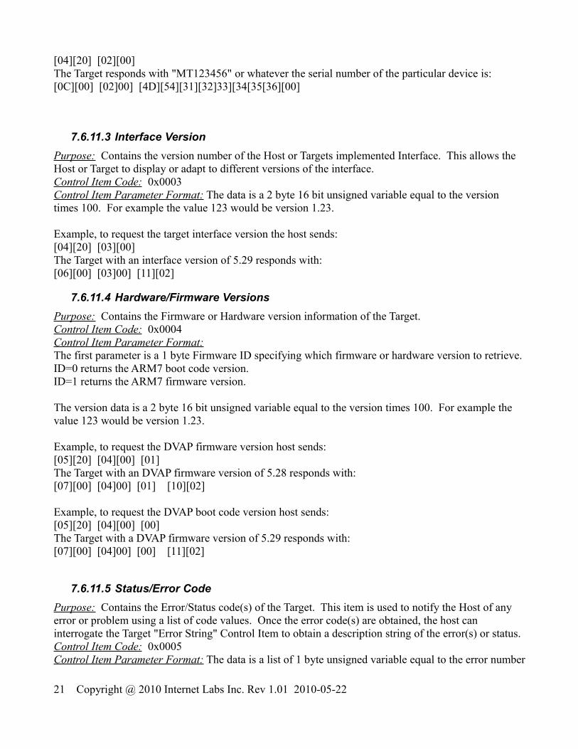
7.6.11.3 Interface VersionPurpose: Contains the version number of the Host or Targets implemented Interface. This allows the Host or Target to display or adapt to different versions of the interface.Control Item Code: 0x0003Control Item Parameter Format: The data is a 2 byte 16 bit unsigned variable equal to the version times 100. For example the value 123 would be version 1.23.
Example, to request the target interface version the host sends:[04][20] [03][00]The Target with an interface version of 5.29 responds with:[06][00] [03]00] [11][02]
7.6.11.4 Hardware/Firmware VersionsPurpose: Contains the Firmware or Hardware version information of the Target. Control Item Code: 0x0004Control Item Parameter Format: The first parameter is a 1 byte Firmware ID specifying which firmware or hardware version to retrieve.ID=0 returns the ARM7 boot code version.ID=1 returns the ARM7 firmware version.
The version data is a 2 byte 16 bit unsigned variable equal to the version times 100. For example the value 123 would be version 1.23.
Example, to request the DVAP firmware version host sends:[05][20] [04][00] [01]The Target with an DVAP firmware version of 5.28 responds with:[07][00] [04]00] [01] [10][02]
Example, to request the DVAP boot code version host sends:[05][20] [04][00] [00]The Target with a DVAP firmware version of 5.29 responds with:[07][00] [04]00] [00] [11][02]
7.6.11.5 Status/Error CodePurpose: Contains the Error/Status code(s) of the Target. This item is used to notify the Host of any error or problem using a list of code values. Once the error code(s) are obtained, the host can interrogate the Target "Error String" Control Item to obtain a description string of the error(s) or status.Control Item Code: 0x0005Control Item Parameter Format: The data is a list of 1 byte unsigned variable equal to the error number
21 Copyright @ 2010 Internet Labs Inc. Rev 1.01 2010-05-22

associated with a particular error. There can be multiple error codes returned by the Target.0x00 = Stopped0x01 = Running0x0E = Boot mode Idle0x0F = Boot mode busy programming0x80 = Boot mode programming errorExample, host request status:[04][20] [05][00]The stopped Target responds with[05][00] [05]00] [00]
7.6.12 DVAP Specific Control Items
7.6.12.1 Run StatePurpose: Controls the operational state of the DVAP.Control Item Code: 0x0018Control Item Parameter Format:
The first parameter is a 1 byte value defined as:0x00 = Stop DVAP in inactive idle state0x01 = Run DVAP in active state normally receiving unless in a test mode
The DVAP will save any changed settings into its non-volatile memory when the “Stop” message is received.
When the DVAP is in the analog FM mode, receive data packets will continually be sent as long as the DVAP is in the Run state even while transmitting. The host can use these data packets to synchronize the transmit packets and/or with soundcard data.
Example: Request to start the DVAP running:The host sends:[05][00] [18][00] [01] The Target responds with:[05][00] [18][00] [01]
7.6.12.2 DVAP Modulation TypePurpose: Controls the Modulation type of the DVAP (FM or DSTAR GMSK).Control Item Code: 0x0028Control Item Parameter Format:
The First parameter defines the modulation type and is a 1 byte value defined as:0x00 = FM(default)0x01 = D-Star GMSK Data Mode.
22 Copyright @ 2010 Internet Labs Inc. Rev 1.01 2010-05-22

This message can only be sent when the DVAP is in the "OFF" mode and not running.Example: Request to setup the DVAP for DSTAR GMSK mode:The host sends:[05][00] [28][00] [01] The Target responds with:[05][00] [28][00] [01]
7.6.12.3 DVAP Operation ModePurpose: Controls the operational Mode of the DVAP(normal or test modes).Control Item Code: 0x002AControl Item Parameter Format:
The First parameter defines the operation mode and is a 1 byte value defined as:0x00 = Normal Transceiver Mode(default)0x01 = CW Test Mode. --transmits continuous carrier when PTT is on0x02 = Deviation Test Mode. --transmits deviation test carrier when PTT is on
This message can only be sent when the DVAP is in the "OFF" mode and not running.Example: Request to setup the DVAP for CW Test Mode:The host sends:[05][00] [2A][00] [01] The Target responds with:[05][00] [2A][00] [01]
7.6.12.4 DVAP Squelch ThresholdPurpose: Controls the Squelch Threshold of the DVAP.Control Item Code: 0x0080Control Item Parameter Format:
The First parameter defines the squelch threshold and is a signed 1 byte value:The range is -128dBm(0x80) to -45dBm(0xD3). Any signal above this threshold will "Open" thesquelch.If the threshold is set to minimum, -128dBm(0x80), then the squelch is forced open regardless of signal level.
Example: Request to setup the DVAP squelch threshold to -100 dBm:The host sends:[05][00] [80][00] [9C] The Target responds with:[05][00] [80][00] [9C]
7.6.12.5 DVAP Operational StatusPurpose: Reports the receiver Signal level(RSSI) and Tx FIFO status of the DVAP.Control Item Code: 0x0090
23 Copyright @ 2010 Internet Labs Inc. Rev 1.01 2010-05-22

Control Item Parameter Format:
The First parameter is the current the receiver signal RSSI level and is a signed 1 byte value:The range is -127dBm to -45dBm during receive. It is set to 0 during transmit.
The Second parameter is the current the squelch State and is a one byte value:0x00 = Squelch closed (no signal or transmitting)0x01 = Squelch open (Rx signal RSSI above squelch threshold or processing D-Star data)
The Third parameter is the number of voice data packets that can be placed in the DVAP FIFO. It is used to determine how near full or empty the FIFO is:0 == Indicates Queue is Full and any packets sent will be ignored.127 == Indicates Queue is empty and Tx operation will soon terminate.
This msg is sent every 20 milliseconds as long as the DVAP is in the Run mode.It is an unsolicited type msg and does not need to be requested.
Example: DVAP Operational Status messages:The Target sends every 20mSecs while in GMSK running mode:[07][20] [90][00] [B5] [01] [7F] //-75dBm squelch open[07][20] [90][00] [9C] [00] [7F] //-100dBm squelch closed[07][20] [90][00] [00] [00] [12] //Transmitting Tx fifo can except up to 18 new packets
7.6.12.6 DVAP PTT StatePurpose: Sets/Reports the PTT State of the DVAP.Control Item Code: 0x0118Control Item Parameter Format:
The First parameter is a 1 byte value of the PTT state:0x00 = Receive Active0x01 = Transmit Active.
This message is sent whenever there is a change in the PTT state of the DVAP as an unsolicited type msg (does not need to be requested).
The host does not need to send this message to set the DVAP PTT state to transmit for the normal D-Star mode where the “GMSK Mode D-Star Header Data Item 1” message automatically starts the transmission mode or when FM transmit data packets are received. It can be sent but will be ignored as will any PTT off messages.
The DVAP will automatically return to the receive PTT state when no more data packets are sent to it and all remaining data packets have been transmitted so there is no need to send a PTT receive message.
Example: DVAP PTT messages:
24 Copyright @ 2010 Internet Labs Inc. Rev 1.01 2010-05-22

The Target sends unsolicited message whenever PTT changes:[05][20] [18][01] [01] // Transmitter ON[05][20] [18][01] [00] // Transmitter OFF(receiver ON)
7.6.12.7 DVAP External T/R Control ModePurpose: Sets the mode for the external T/R control pin of the DVAP.Control Item Code: 0x011AControl Item Parameter Format:
The DVAP has a control pin that is an open drain active low signal that can drive an external relay or device.
The First parameter is a 1 byte value of the T/R control pin mode:0x00 = Inactive High continuous(default)0x01 = Active Low continuous0x02 = Active Low during Transmit0x03 = Active Low during Receive0x04 = Active Low during Receive and Squelch is Open(receiving a signal)0x05 = DTMF 'A' key Active Low, DTMF 'B' key Inactive High0x06 = DTMF 'A' key Active Low while key pressed, Inactive High on key release
Example: Request to set T/R pin Active low during transmit:The host sends:[05][00] [1A][01] [02] The Target responds with:[05][00] [1A][01] [02]
7.6.12.8 DVAP Manual LED ControlPurpose: Sets the LED mode and values for host control of the 3 DVAP LED's.Control Item Code: 0x011CControl Item Parameter Format:
The DVAP allows the host to manually control three of the LED's or allow the DVAP to automatically control them.
The First parameter is a 1 byte LED mode:0x00 = DVAP controls the LED's(default)0x01 = Host Controls the LED's
The Second parameter byte is the Yellow LED Intensity range( 0==Off to 100==Full On)The Third parameter byte is the Red LED Intensity range( 0==Off to 100==Full On)The Fourth parameter byte is the Green LED Intensity range( 0==Off to 100==Full On)
Example: Request to manually set all LED's to half intensity:The host sends:
25 Copyright @ 2010 Internet Labs Inc. Rev 1.01 2010-05-22

[05][00] [1C][01] [01] [32][32][32]The Target responds with:[05][00] [1C][01] [01] [32][32][32]
Example: Request to go back to automatic LED operation(LED intensity parameters are ignored):The host sends:[05][00] [1C][01] [00] [00][00][00]The Target responds with:[05][00] [1C][01] [00] [00][00][00]
7.6.12.9 DVAP Receiver FrequencyPurpose: Controls the receiver frequency of the DVAP.Control Item Code: 0x0020Control Item Parameter Format:
The first 4 parameter bytes are a 32bit frequency value in little endian format.The range is 144.0MHz to 148.0 MHz for the 2m version.(0x08954400 to 0x08D24D00)
Example: Request to set the DVAP Rx frequency to 146.520MHz (0x08BBB7C0):
The host sends:[08][00] [20][00] [C0] [B7] [BB] [08] The Target responds with:[08][00] [20][00] [C0] [B7] [BB] [08]
7.6.12.10 DVAP Transmit FrequencyPurpose: Controls the transmit frequency of the DVAP.Control Item Code: 0x0120Control Item Parameter Format:
The first 4 parameter bytes are a 32bit frequency value in little endian format.The range is 144.0MHz to 148.0 MHz for the 2m version.(0x08954400 to 0x08D24D00)
Example: Request to set the DVAP Tx frequency to 146.520MHz (0x08BBB7C0):
The host sends:[08][00] [20][01] [C0] [B7] [BB] [08] The Target responds with:[08][00] [20][01] [C0] [B7] [BB] [08]
7.6.12.11 DVAP Transmit and Receive FrequencyPurpose: Controls the transmit and receive frequency of the DVAP.Control Item Code: 0x0220Control Item Parameter Format:
26 Copyright @ 2010 Internet Labs Inc. Rev 1.01 2010-05-22

The first 4 parameter bytes are a 32bit frequency value in little endian format.The range is 144.0MHz to 148.0 MHz. (0x08954400 to 0x08D24D00)
Example: Request to set the DVAP Tx and Rx frequency to 146.520MHz (0x08BBB7C0):
The host sends:[08][00] [20][02] [C0] [B7] [BB] [08] The Target responds with:[08][00] [20][02] [C0] [B7] [BB] [08]
7.6.12.12 DVAP TX Frequency Limits Read OnlyPurpose: Allows Reading only of the transmit frequency limits.Control Item Code: 0x0230Control Item Parameter Format:
The first 4 parameter bytes are a 32bit frequency Lower Limit in little endian format.The range is 144.0MHz to 148.0 MHz .(0x08954400 to 0x08D24D00)
The second 4 parameter bytes are a 32bit frequency Upper Limit in little endian format.The range is 144.0MHz to 148.0 MHz .(0x08954400 to 0x08D24D00)
Example: Request the DVAP Tx frequency limits:The host sends:[04][20] [30][02] The Target responds with:[08][00] [30][02] [00] [44] [95] [08] [80] [C8] [B3] [08]
7.6.12.13 DVAP TX Power SettingPurpose: Sets the DVAP Transmitter power.Control Item Code: 0x0138Control Item Parameter Format:
The first 2 parameter bytes are a signed 16 bit value of dBm in little endian format.The maximum power is +10 dBm( 0x000A)The minimum power is -12 dBm( 0xFFF4)
Example: Set the DVAP Tx power to -10dBm (0xFFF6):The host sends:[06][00] [38][01] [F6] [FF] The Target responds with:[06][00] [38][01] [F6] [FF]
27 Copyright @ 2010 Internet Labs Inc. Rev 1.01 2010-05-22

7.6.12.14 DVAP Frequency CalibrationPurpose: Sets the reference frequency calibration of the DVAP.Control Item Code: 0x0400Control Item Parameter Format:
The first 4 parameter bytes are a 16 bit frequency offset value in little endian format.The nominal crystal reference frequency is 19.6608MHz and this offset value is added to the nominal reference crystal value when calculating the PLL output frequency.The adjustment range is +/-2000Hz or about +-100ppm.
Example: Set the DVAP crystal reference frequency offset to -230Hz (0xFF1A):
The host sends:[06][00] [00][04] [1A] [FF] The Target responds with:[06][00] [00][04] [1A] [FF]
7.6.12.15 DVAP Band ScanPurpose: Performs a scan of the band of N Steps from Start Frequency in StepSize steps and returns the RSSI for each point.Control Item Code: 0x0404Control Item Parameter Format:
The first parameter is the 16 bit number of steps to scan in little endian format(1 to 800max).The second parameter is the 8 bit step size in 100 Hz increments to scan(100 to 25500Hz).The third 4 byte parameter is a 32 bit scan start frequency Hz in little endian format.
Make sure the scan range will fall in the valid frequency range of the DVAP.The total scan time is a function of the number of points and is roughly 1 mSec per point.The RSSI value for each point is a signed byte representing the dBm value of the signal.
Ex: The host requests to scan 206 Points with 1100 Hz step size starting at 145.0MHz (145.00 MHz to 145.225500 MHz in 1100Hz steps ):[0B][20] [04][04] [CE][00] [0B] [40][86][A4][08]The Target responds with after the scan is complete( ):[D2][00] [04][04] [rssi_1] [rssi_2] …..[rssi_206]
28 Copyright @ 2010 Internet Labs Inc. Rev 1.01 2010-05-22

7.6.12.16 DVAP DTMF MessagePurpose: Signals the reception of a DTMF key press or release.Control Item Code: 0x0406Control Item Parameter Format:
This is an unsolicited message that is sent by the DVAP whenever a DTMF key is pressed or released while in FM receive mode.The one byte parameter is the ASCII code for the key(0 to 9, #, *, and A,B,C,D).A zero is sent when the key is released.
Ex: The 3 key is decoded so the DVAP sends:[05][20] [06][04] [33] Ex: The key is released so the DVAP sends:[05][20] [06][04] [0]
7.6.13 DVAP WatchDog Keepalive MessagePurpose: Must be sent at least every 3 seconds while the DVAP is running or the DVAP will automatically turn of the Tx if on and go to Idle mode. This is to prevent the DVAP from continuously trying to transmit or send the Operation Status message if the Host disconnects while running.
Any message can be sent to the DVAP to keep it alive. The shortest message one can send is the 3 byte ACK message.
A Data Item "ACK" message is a 16 bit header with a Message Type = 011b with a single parameter byte specifying the Data Item (0 to 3). The header is a fixed value (0000 0011 0110 0000 ).
For example the Host could send the following to the Host at least every 3 seconds to keep it running:[03][60] [00]
29 Copyright @ 2010 Internet Labs Inc. Rev 1.01 2010-05-22

7.6.14 DVAP Data Item Definitions
7.6.14.1 DVAP FM mode (Data Item 0)Purpose: This is the uncompressed audio data item message that is sent/received by the host when the DVAP is receiving and transmitting FM audio data.Data 0 Item Parameter Format: All data 0 blocks to/from the DVAP are fixed size of 160, 16 bit samples containing 320 bytes of data with the 2 byte data item 0 header.
0x42 0x81 320 Data Bytes
The 320 data bytes represent 160, 16 bit sample values representing the 8000sps PCM uncompressed audio.
The byte breakdown for the data:S1lsb
S1msb
S2lsb
S2msb
……..
S160msb
S160lsb
7.6.14.2 DVAP GMSK Mode DSTAR Header (Data Item 1)Purpose: This is the 41 byte DSTAR header data item message for transmit or receive.
Data 1 Item Parameter Format: The format of this message is the Dstar standard data format and is 47 ( 45 + 2 header bytes) in length.
0x2F 0xA0 45 Data Bytes
struct{U8BIT hdr0; //ASCP header low byte 0x2FU8BIT hdr1; //ASCP header high byte 0xA0U16BIT StreamID; //see Data Item 2 descriptionU8BIT FramePos; //see Data Item 2 descriptionU8BIT Seq; //see Data Item 2 descriptionU8BIT flags1;U8BIT flags2;U8BIT flags3;U8BIT rpt1[8];U8BIT rpt2[8];U8BIT urcall[8];
30 Copyright @ 2010 Internet Labs Inc. Rev 1.01 2010-05-22

U8BIT mycall[8];U8BIT mysuffix[4];U8BIT pfcs[2];}fld;
7.6.14.3 DVAP GMSK Mode DSTAR Header TX ACK messagePurpose: This message is sent back to the Host after a D-Star header has been transmitted before any voice/data packets.
Data Ack Format: The format of this message is the Dstar standard data format and is 47 ( 45 + 2 header bytes) in length.
0x2F 0x60 45 Data Bytes
struct{U8BIT hdr0; //ASCP header low byte 0x2FU8BIT hdr1; //ASCP header high byte 0xA0U16BIT StreamID; //see Data Item 2 descriptionU8BIT FramePos; //see Data Item 2 descriptionU8BIT Seq; //see Data Item 2 descriptionU8BIT flags1;U8BIT flags2;U8BIT flags3;U8BIT rpt1[8];U8BIT rpt2[8];U8BIT urcall[8];U8BIT mycall[8];U8BIT mysuffix[4];U8BIT pfcs[2];}fld;
7.6.14.4 DVAP GMSK Mode DSTAR Voice/Slow Data (Data Item 2)Purpose: This is the DSTAR voice-slow data item message for transmit or receive.
Data 2 Item Parameter Format: The format of this message is the Dstar standard voice/data packet format and is 12+4+2 header bytes in length.
StreamID is a 16 bit ID for the current data stream.FramePos is a 5 bit counter indicating packet position within frame (0==Sync packet). Bit7,6,5 are flags.Increments from 0 to 20 indicating packet position within 21 packet Voice Data frameBit 7 == Header packetBit 6 == End of Stream packetBit 5 == Using previous Header packet
31 Copyright @ 2010 Internet Labs Inc. Rev 1.01 2010-05-22

Seq is an 8 bit packet sequence number, zeroed when StreamID changes.
0x12 0xC0 StreamID0 StreamIID1 FramePos Seq 12 Voice/SlowData Bytes
32 Copyright @ 2010 Internet Labs Inc. Rev 1.01 2010-05-22