Embed Size (px)
Citation preview

Contractor Report 191049
I
s-i ?.I/t
DVANCED EXPANDER TEST BED PROGRAM
>
IAL TECHNICAL PROGRESS REPORT FOR 1992
& Whitney
Engines & Space PropulsionBox 109600Palm Beach, FL 33410-9600
1993
(NASA-CR-191049) ADVANCE9 EXPA_CER
TEST BEO PROGRAM Annual Technic31
Progress Report, i Jan. - 31 Dec.1992 (United Technologies Corp.)
27 p
O3/ZO
N93-19991 i
Unclas
0148128
for:
Contract
A¢
https://ntrs.nasa.gov/search.jsp?R=19930010802 2018-08-29T16:00:39+00:00Z

Section
I
II
1II
IV
CONTENTS
Page
INTRODUCTION ............................................. I-1
EXECUTIVE SUMMARY ........................................ II-1
TECHNICAL PROGRESS ....................................... III-1
m. TASK 1.0 -- PROGRAM MANAGEMENT .......................... III-1
1. Reports ............................................ III-1
2. Meetings ........................................... III-1
3. System Safety, Reliability, and Quality Control ..................... III-1
B. TASK 2.0 -- DESIGN AND ANALYSIS METHODOLOGY ................ III-2
1. Steady-State Cycle Analysis ................................ III-2
2. Transient Cycle Analysis .................................. 11I-2
C° TASK
1.
2.
3.
4.
5.
6.
4.0 -- FINAL DESIGN .................................. 1II-5
Oxidizer Turbopump .................................... III-5
Hydrogen Turbopump ................................... III-7
Thrust Chamber Assembly ................................. III-10
Electronic Controller, Valves, and Sensors ........................ 111-13
Hydrogen Mixer ....................................... III-16
System Integration ..................................... Ili-17
D. TASK 8.0 -- TECHNICAL ASSISTANCE ........................... III-17
CURRENT PROBLEMS AND FUTURE WORK .......................... IV-1
Figure
I-1
II-1
III-I
III-2
III-3
III-4
III-5
III-6
III-7
III-8
III-9
LIST OF ILLUSTRATIONS
Page
Advanced Expander Test Bed Assembly ............................ I-2
Advanced Expander Test Bed Schedule ............................. II-2
Advanced Expander Test Bed Flow Schematic ....................... III-3
Advanced Expander Test Bed Transient Model of Start and Shutdown .......... III-4
Advanced Expander Test Bed Oxidizer Turbopump ..................... III-5
Advanced Expander Test Bed Hydrogen Turbopump .................... III-8
Advanced Expander Test Bed Thrust Chamber Assembly ................. III-10
IR&D Igniter Undergoing Testing ............................... III-11
Copper Tubular Combustion Chamber ............................ III-13
Advanced Expander Test Bed Fiber Optic Turbopump Shaft Speed Sensor ....... III-15
Hydrogen Mixer ......................................... III-16
ii

Table
I-1
III-1
LIST OF TABLES
Page
Advanced Expander Test Bed Goals .............................. I-1
Advanced Expander Test Bed Speed Sensor Specifications ................ Ili-14
iii

SECTION IINTRODUCTION
Mission studies at NASA have identified the need for a new Space Transfer Vehicle Propulsion System. The
new system -- an oxygen/hydrogen expander cycle engine -- must achieve high performance through efficient
combustion, high combustion pressure, and high area ratio exhaust nozzle expansion. The engine should feature
a high degree of versatility in terms of throttleability, operation over a wide range of mixture ratios, autogenous
pressurization, inflight engine cooldown, and propellant settling. Firm engine requirements include long life,
man-rating, reusability, space-basing, and fault-tolerant operation.
The Advanced Expander Test Bed (AETB), shown in Figure I-1, is a key element in NASA's Space
Chemical Engines Technology Program for development and demonstration of expander cycle oxygen/hydrogen
engine technologies and advanced technology components applicable to space engines and launch vehicle upper-
stage engines. The AETB will be used to validate the high-pressure expander cycle concept, investigate system
interactions, and conduct investigations of advanced mission focused components and new healthy monitoring
techniques. The split-expander cycle AETB will operate at combustion chamber pressures up to 1200 psia with
propellant flowrates equivalent to 20,000-1bf vacuum thrust. The requirements are summarized in Table I-1.
The program is divided into eight tasks. Preliminary Design (Task 3.0) was completed on 31 January 1991
and followed by Final Design (Task 4.0). Two AETBs will be fabricated, assembled, and acceptance-tested at
Pratt & Whitney (P&W). Both AETBs will then be delivered to NASA-Lewis Research Center, where the bulk
of the testing will be conducted. Development and verification of advanced design methods are another goal of
the AETB program. Under Design and Analysis Methodology (Task 2.0), steady-state and transient simulation
codes will be produced. These two codes and selected design models will be verified during component and
engine acceptance testing. The remaining tasks deal with Program Management (Task 1.0), Fabrication (Task
5.0), Component Tests (Task 6.0), Engine Acceptance (Task 7.0), and NASA Technical Assistance (Task 8.0).
Table 1-1. Advanced Expander Test Bed Goals
Propellants
Cycle
Thrust
Pressure
Mixture Ratio
Throttling
Propellant Inlet Conditions:
Hydrogen
Oxygen
Idle Modes
Life
Oxygen/Hydrogen
Expander
Nominal 20,000 lbf
Nominal 1200 psia
6.0 + 1.0 (Optional Operation at 12.0)
100- to 5-Percent Thrust
38°R, 70 psia
163°R, 70 psia
Tankhead (Nonrotating Pumps)
Pumped (Low-NPSH Pumping)
100 Starts, 5 Hours
I-1

Thrust Chamber Assembly
Fuel Turbopump
Oxidizer
Turbopump
Figure 1-1. Advanced Expander Test Bed Assembly
14953
1-2

SECTION IIEXECUTIVE SUMMARY
A major milestone was achieved when the Oxidizer Turbopump Design Review was held on 14-15 September
1992. Review teams from NASA-Lewis Research Center and Marshall Space Flight Center participated. A similar
review will be held for the fuel turbopump in the second quarter of 1993, as shown in the schedule in Figure II-1.
Due to constraints on the Advanced Expander Test Bed Program (AETB) budget for fiscal years 1992 and
1993, final design has, by necessity, proceeded at a uniform, but slower pace than anticipated at program inception.
Oxidizer and hydrogen turbopump designs have been the focus of the program up to this point. The control and
engine system design that was on hold during most of 1992, will receive a greater share of the work in 1993.
The mixer, the turbopump speed sensors, and three of the AETB control valves were designed in 1992.
These three control valves were placed on order early to support thrust chamber rig testing by Pratt & Whitney.
The valves will be delivered by the suppliers in the next quarter and reported under Task 5.0, Fabrication
and Assembly.
II-1

o
I=0
m
U
0a
• o _ I_ _ •
0 0 0 o 0 0 0 0
II-2
SECTION III
TECHNICAL PROGRESS
A. TASK 1.0 -- PROGRAM MANAGEMENT
The Program Management Task includes:
• Program Control and Administration
• Reports
• Travel and Meetings
• System Safety, Reliability, and Quality Control.
1. Reports
The following reports were published in 1992:
• Second Annual Technical Progress Report, Contractor's Report CR189130 (for calendar year 1991),March 1992.
• Technologies Embodied in the AETB (special report at NASA's request), 23 March 1992.
• Product Assurance Plan (FR-21320-2), May 1992.
• Design and Analysis Methodology Report and Verification Plan (FR-21323), 31 August 1992.
• AETB Program Quarterly Technical Progress Reports for each quarterly period (FR-21318-11, -12,-13).
2. Meetings
• A Pratt & Whitney (P&W) chief engineer's review of the oxidizer turbopump was conducted on 16July 1992.
• A Design Status Review was held at NASA-Marshall Space Flight Center (NASA-MSFC) on 24 June1992.
• A formal Oxidizer Turbopump Design Review was held at GESP on 14-15 September 1992 with
NASA-Lewis Research Center (NASA-LeRC) and NASA-MSFC personnel in attendance.
• Management meetings were held each month.
3. System Safety, Reliability, and Quality Control
The Product Assurance Plan was updated to reflect the fact that P&W consolidated the product
verification requirements of its various units into a unified system of Total Quality Operations.
A program-level risk assessment was carried out on the oxygen and hydrogen turbopumps. The
assessment was accomplished by assigning probability and impact factors to each item to obtain a risk
factor. The items were then ranked by risk factor and flagged for later verification and mitigation.
III-1

B. TASK 2.0 m DESIGN AND ANALYSIS METHODOLOGY
1. Steady-State Cycle Analysis
The number of internal flows in the steady-state model was combined into two equivalent internal flows
to provide a simpler internal flow calculation within the transient engine model. The two models were then
compared to see if the results correlated. The steady-state and transient models showed good agreement at high
engine power points, but significant differences were noted at lower engine power points. The discrepanciesbetween the models have been reduced by increasing the number of internal flows to 15 in the steady-state model
and 9 in the transient model. The transient model has six fewer flows because six pairs of similar secondary
flows have been combined for the sake of transient model efficiency. The two models now show good agreement
over the full range of engine operation.
2. Transient Cycle Analysis
The AETB transient analysis focused on four major tasks during 1992: (1) development of a controller for
AETB operation, (2) incorporation of transient thrust balance analysis, (3) turbopump inertia study completed,and (4) continued further enhancement of the AETB split expander transient model.
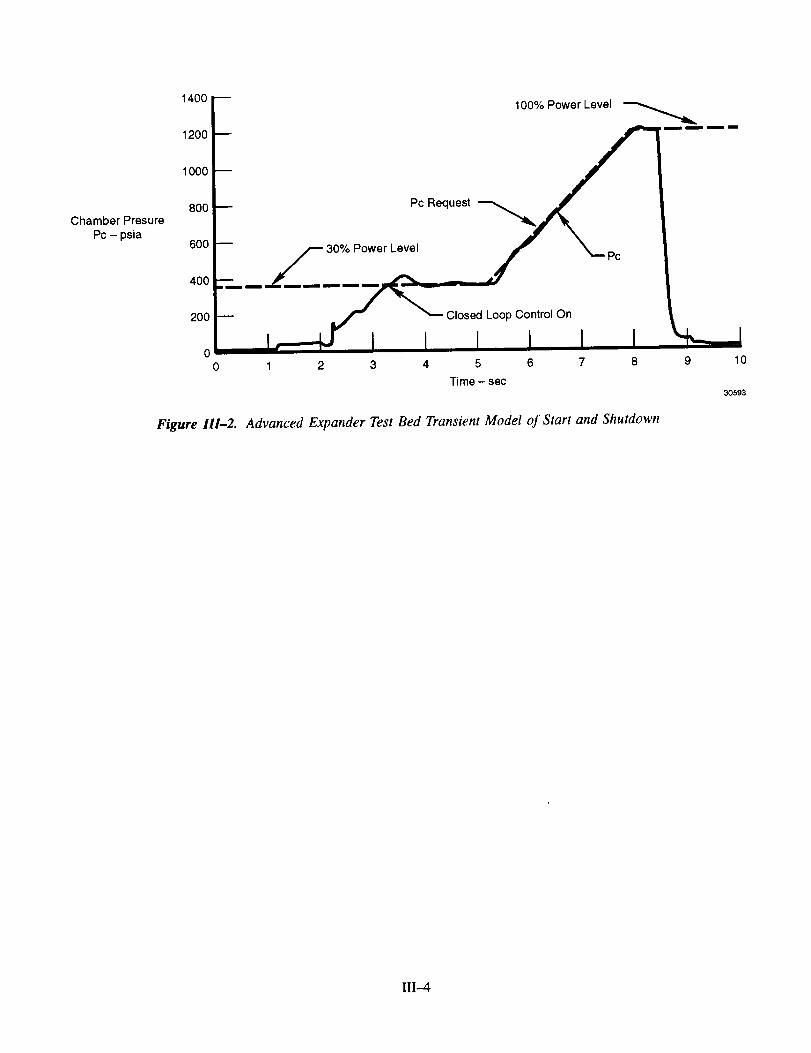
A control module with start, shutdown, and throttle logic was implemented in the transient model. A
Proportional-Integral (PI) controller is used to control the scheduling of the AETB valves, as shown in the flowschematic in Figure III-1. Closed loop thrust control on the main turbine bypass valve (MTBV) is based on
chamber pressure (Pc) request to Pc feedback. The fuel turbine bypass valve (FTBV), fuel jacket bypass valve
(FJBV), secondary oxidizer control valve (SOCV), and the fuel pump recirculation valve (FPRV) are all open
loop control valves. The valves will be scheduled by Pc request, primary fuel pump speed, and measured Pc.All of the valves are modeled with a second order actuator and deadband. The AETB will accelerate at start to
a power level no less than 30 percent of rated power level (Pc = 360 psia) in order to minimize Pc overshoot
experienced by starting to lower power levels. Once the AETB has started to 30 percent (or higher) power
level, the closed loop thrust control can throttle the AETB to higher or lower power levels, as requested. Figure111-2 illustrates how Pc will follow the Pc request for a start to 30-percent power level, a requested ramp to
100-percent power level, and a shutdown from 100-percent power level.
Transient thrust balance analysis has been developed in the AETB transient model to calculate the turbopump
thrust loads and capabilities during start, shutdown, and throttle modes of the AETB. This information was
provided to support the turbopump design efforts.
As a result of liquid oxygen (LOX) turbopump design enhancements, a sensitivity study was performed
on polar moments of inertia of the turbopump rotors. This study supported the design process by determining
acceptable turbopump inertias for controllable starts, and nominal operation of throttle and shutdown modes.An inertia ratio of 6 to 1 (LOX turbopump to fuel secondary turbopump) was shown to be the maximum
acceptable inertia ratio.
The AETB transient model was updated and improved throughout the year. All pump and turbine maps have
been updated. Eight detailed secondary flows have been incorporated to enhance secondary flow model fidelity.
1II-2

x0
ii
iii
5ii.I
IT
ii
o
,
T
>+_++p_
<.,,,+
I,.
III-3
Chamber Presure
Pc - psia
1400 D 100% Power Level
,oii_'_°°- _._,_ .....8 Pc Request
'°°F--".... _ I.o
o0 1 2 3 4 5 6 7 8 9 10
Time - sec30593
Figure 111-2. Advanced Expander Test Bed Transient Model of Start and Shutdown
III-4

C. TASK 4.0 -- FINAL DESIGN
The final design of the AETB began in February 1991. The major effort during 1992 was in the area
of oxidizer and hydrogen turbopump design, with a formal design review of the oxidizer turbopump held in
September.
1. Oxidizer Turbopump
The oxidizer turbopump has a single-stage LOX pump and a single-stage fuel (hydrogen) driven turbine. An
interpropellant seal package, with helium dam, is provided to prevent fuel and oxidizer from coming in contact.
The rotor is supported by two ball bearings that support axial loads, and a roller bearing that supports radial
loads and provides stiffness. Following the Design Review of the oxidizer turbopump, the engineering layout of
the turbopump was essentially completed by the end of the year. Major design developments during the year are
discussed in the following paragraphs and a design cross-section is shown in Figure III-3.
Area ofRotor Inertia
Reduction
Honeycomb Turbine VoluteTip Shroud Insert
Sensor
Rotor TorqueCheck and
Access Port
Vent (Optional)
Vaporizer -J_
InterpropeUant Seal
Figure III-3. Advanced Expander Test Bed Oxidizer Turbopump
_oosa
111-5

a. Rotor and Housings
Thrust balance analysis was completed for four steady state rated power levels: 4, 15, 20, and 25Klbf thrust.
Based on this analysis, the rotor steady state thrust loads were predicted to be within the capability of the ball
bearings at all power levels. As added margin in controlling thrust balance axial loads, a venting scheme wasadded to the rear cavity of the turbopump. This cavity can be vented, if necessary, to compensate for high loads
toward the pump end. The hydrogen vented from the cavity will be returned to the 2nd-stage fuel pump inlet
without significant impact on performance.
Thermal models of the entire turbopump were generated for both the 25,000 and 20,000 lbf thrust power
levels. Structural analysis was then based on the 25K point only, and running and build clearances were assessed
using the values from the 20K thermal analysis.
Preliminary results from the housing stress analysis showed excessive thermal stresses in the inner flange ofthe turbine volutes. These stresses were lowered to a level below the allowable stress by changing the material
from A286 to INCO 909, which has a lower coefficient of thermal expansion. However, concern about transient
stresses led to further design changes to isolate the cold flange from the hot volute towpath.
The rotor material was changed from A286 to IN-100 to reduce preload stresses at assembly. Also, the
pump end of the rotor was reconfigured to incorporate a longer tiebolt to achieve the proper amount of rotorpreload at assembly. Other changes were made to the front end of the rotor to straighten the load path through
the rotor stack. These changes ensure load path integrity and rotor stiffness at all operating conditions.
A sensitivity study was conducted to determine the effects of clearance increases within the interpropellant
seal (IPS) package. Results showed that internal clearances between the knife edges and the lands would have
to increase to over 0.050 inches to compromise the integrity of the helium dam. The study also revealed that,
if the secondary hydrogen seal (the one nearest the helium dam), opens more than 43 percent, warm hydrogen
may be drawn from the turbine towpath down the front face of the disk. This will heat the disk and could
cause it to bend, opening turbine tip clearance and decreasing performance. Although no serious incidents are
anticipated should this happen, work is in progress to reduce the sensitivity of the system to this increasedseal clearance should it occur.
Features have been added to the aft end of the turbopump to allow a static torque check of the rotor and
to provide the ability to measure rotor axial end play as an indication of ball bearing wear. Both checks can
be performed between test runs while the pump is on the test stand. These features are important in monitoring
the health of the pump.
Transient analysis performed under Task 2.0 revealed that the engine would be difficult to start due to
the high oxidizer turbopump rotor polar moment of inertia compared to the hydrogen turbopump. The LOX
turbopump excessive turbine blisk thickness was reduced to the present configuration to solve this problem.
Structural analysis showed stress margins to be acceptable.
Turbine running clearance should be as tight as possible to ensure good performance. A turbine outer seal
insert of honeycomb material was incorporated as a ruggedness feature to provide a passive, yielding surface in
the event of rotor-to-seal contact resulting from an unexpected occurrence during transient operation.
III-6

b. Stresses
Housing Structural Analysis -- Analysis of the LOX turbopump housings with a two-dimensional (2-D) bodyof revolution finite element model was completed. The analysis incorporated revised features such as cantilever
flanges to maintain closure at the seals and radially splined turbine inlet and discharge volutes to compensate fora thermal mismatch with the main housings. Stress concentrations for all holes and notched areas were evaluated
and found to be acceptable for full low-cycle fatigue (LCF) life requirements. Deflections at all critical sealing
locations were determined so operating clearances could be set.
Vaporizer Structural Analysis -- NASA-LeRC completed analysis of the vaporizer using a 2-D body of
revolution finite element model. Steady and vibratory stress margins and LCF life were acceptable.
Rotor Stack Analysis -- A 2-D body of revolution finite element model was used to analyze the complete
rotor stack assembly. An axial load was determined for the rotor, as assembled, to ensure adequate load remains
in the rotor over the full operating speed range to maintain rotor stiffness and critical speed margin requirements.
The analysis determined that all snap fits remained tight during chill down and operating, and confirmed that the
longer stretch section in the pump end tiebolt (discussed above) would be a desirable improvement in setting
stack loads. Analysis of the revised configuration to meet this goal will be completed in early 1993.
2. Hydrogen Turbopump
The liquid hydrogen turbopump has primary and secondary segments that are arranged back-to-back and are
counterrotating. The first stage of the pump, driven by the lst-stage turbine, has an axial inlet. The 2nd- and
3rd-stages of the pump, driven by the 2nd-stage turbine, have dual radial inlets. The turbine flowpath, which
operates at much higher temperatures than the pump stages at either end, is provided with shields to isolate
the housings and reduce deflect ions due to thermal stresses. The rotors are supported by two roller bearings
per shaft and operate below their critical speeds. The major design activities for the year are discussed in the
following paragraphs and a cross-section is shown in Figure III-4.
111-7

E
cl
I
III-8
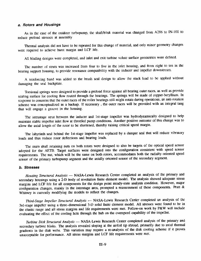
a. Rotors and Housings
As in the case of the oxidizer turbopump, the shaft/blisk material was changed from A286 to IN-100 to
reduce preload stresses at assembly
Thermal analysis did not have to be repeated for this change of material, and only minor geometry changes
were required to achieve burst margin and LCF life.
All blading designs were completed, and inlet and exit turbine volute surface geometries were defined.
The number of struts was increased from four to five in the inlet housing, and from eight to ten in the
bearing support housing, to provide resonance compatibility with the inducer and impeller downstream.
A reinforcing band was added to the brush seal design to allow the stack load to be applied without
damaging the seal backplate.
Torsional springs were designed to provide a preload force against all bearing outer races, as well as provide
sealing surface for cooling flow routed through the bearings. The springs will be made of copper-beryllium. In
response to concerns that the outer races of the roller bearings still might rotate during operations, an anti-rotation
scheme was conceptualized as a backup. If necessary, the outer races will be provided with an integral tang
that will engage a groove in the housing.
The intrastage strut between the inducer and lst-stage impeller was hydrodynamically designed to help
maintain stable impeller inlet flow at throttled pump conditions. Another positive outcome of this change was to
allow the axial length of the rotor to be shortened, thereby raising critical speed margin.
The labyrinth seal behind the lst-stage impeller was replaced by a damper seal that will reduce vibratoryloads and thus reduce rotor deflections and bearing loads.
The main shaft retaining nuts on both rotors were designed to also be targets of the optical speed sensor
adopted for the AETB. Target surfaces were designed into the configuration consistent with speed sensor
requirements. The nut, which will be the same on both rotors, accommodates both the radially oriented speedsensor of the primary turbopump segment and the axially oriented sensor of the secondary segment.
b. Stresses
Housing Structural Analysis -- NASA-Lewis Research Center completed an analysis of the primary and
secondary housings using a 2-D body of revolution finite element model. The analysis showed adequate stress
margins and LCF life for all components for the design point steady-state analysis condition. However, major
configuration changes, mainly in the interstage area, prompted a reassessment of these components. Pratt &
Whitney is currently modifying the models to reflect the changes.
Third-Stage Impeller Structural Analysis -- NASA-Lewis Research Center completed an analysis of the
3rd-stage impeller using a three--dimensional 3-D solid finite element model. All stresses were found to be in
the elastic range and all stress margins and life requirements were met. Follow-on work by P&W will include
evaluating the effect of the cooling hole through the hub on the overspeed capability of the impeller.
Turbine Disk Structural Analysis -- NASA-Lewis Research Center completed analysis of the primary and
secondary turbine blisks. The analysis revealed sloping at the airfoil tip shroud, primarily due to axial thermal
gradients in the disk webs. This variation may require a re-analysis of the disk cooling scheme if it proves
unacceptable for performance. All stress margins and LCF life requirements were met.
111-9

Rotor Stack Analysis -- Structural models of the primary and secondary rotor stack have been developed
using a 2-D body of revolution elements. Initial assembly and operating point cases have been completed and are
being iterated to obtain the desired running loads. High stress was seen in the lst-stage impeller puller groove
and the adjacent bearing race retainer fillet radius. These features have been modified to provide acceptablestress levels. No stress or life limitations were indicated for any other components.
3. Thrust Chamber Assembly
The thrust chamber assembly consists of a thrust mount, an injector with igniter, a combustion chamber,
and a conical nozzle extension. The AETB injector and combustor are based on configurations being designed,
fabricated, and tested under the auspices of P&W Space Engine Component Technology (IR&D) Programs. The
injector incorporates 65 dual-orifice LOX elements and fuel sleeves, a porous face plate, and an axis-mounted
torch igniter. The combustion chamber, previously a milled channel configuration with an electroformed structural
jacket, has been changed to a copper tubular design. The nozzle extension features nickel alloy coolant tubesbrazed to inlet and outlet manifolds and to a structural jacket. An overall view of the thrust chamber assembly
is shown in Figure III-5.
Igniter
Combustion
Chamber 1
NozzleExtension
Thrust jMount
Injector30591
Figure 111-5. Advanced Expander Test Bed Thrust Chamber Assembly
a. Injector
Fabrication of the detail parts of the injector was completed, and fabrication of the injector assembly wasinitiated. The LOX elements, fuel sleeves with nozzles, LOX manifold cover, and fuel manifolds have been
assembled, and intermediate LOX system flow tests, using water as the test fluid have been successfully carried
out.
Following fabrication of the igniter, testing was successfully carried out to establish its performance. The
testing, which took place in December 1992, defined the injector's operating characteristics over a range of
mixture ratios and propellant flows. Figure Ili--6 shows the igniter in operation.
III-10

_o
°_
_3
III-11
ORIGINAL PAGE
COLOR PHOTOGRAPH

b. Combustion Chamber
Originally, the baseline configuration for the AETB combustion chamber was a milled channel copper
combustor with an electroformed copper closeout and structural jacket. This configuration was selected because
it represented the state of the art at the inception of the AETB program. Pratt & Whitney initiated an IR&D
program to validate the use of its heat transfer design methodology in AETB-class combustors. Concurrently,
a program to develop the technologies required to design and fabricate a copper tubular combustor was also
begun, but this development was not expected to be completed in time for test bed delivery. However, due toadjustments in the AETB schedule, enough progress has been made in the copper tubular combustor technologies
such that they have matured to the point of being feasible for the program. Therefore, the program decision was
made to change the AETB baseline design to incorporate a copper tubular combustor.
In 1992, both IR&D programs continued concurrently. The milled channel combustor liner jacket has beenelectroformed, and the liner is being prepared for installation of the manifolds. A test of the thrust chamber
assembly using this combustion chamber is planned for 1993 to determine combustion characteristics of the
injector and to verify chamber heat transfer design and analysis methodologies.
In the area of copper tubular combustor development, P&W has been working on the development of three
major technologies: a high-strength copper alloy that can withstand elevated fabrication temperatures; a brazingmethod suitable for this alloy; and a vacuum plasma-sprayed (VPS) alloy to produce the structural jacket.
A dispersion strengthened copper alloy, designated as PWA 1176 (raw material), and PWA 1177 (drawn
tubing) has been subjected to preliminary laboratory evaluation, and has been found to retain high strength after
being subjected to the elevated temperatures of the brazing cycle. Design of a rig to provide LCF data is underway.
A braze development program was executed to optimize the braze parameters (temperature, time, braze alloy,
and surface preparation) using designed experiment (Taguchi) techniques. The first confirmation run using the
optimized parameters, in which a tube bundle was brazed into rings which simulated the tube-to-socket joints,resulted in excellent tube-to-tube and tube-to-socket joints. Another tube bundle is being prepared to carry outan additional confirmation run.
The structural jacket will be applied using VPS material over a brazed tube bundle. AISI 347 stainless steel
was selected as the jacket material due to its coefficient of thermal expansion, which is similar to that of copper,and because it is a well-known material. Laboratory testing established the optimum parameters for spraying
and subsequent processing of the VPS material.
The design of an AETB-class combustor was started, and the copper tube drawing has been released to
suppliers in order to obtain quotations. Design of the combustion chamber is ongoing. A preliminary design is
presented in Figure Ill-7. This IR&D design will be used as a basis for the AETB contractual design.
III-12

j-- Wrought "_
'li <
PWA 1177Tubes
30592
Figure 111-7. Copper Tubular Combustion Chamber
c. Nozzle
Intermediate design of the conical nozzle extension was carried out from Janualy tO March 1992, at which
point it was halted due to lack of funding. As designed, the nozzle incorporates Haynes 188 (TM) material tubesbrazed into manifolds, with a stiffening band around the outside of the tube bundle, and a thermal compensating
arm at the front flange where the nozzle interfaces with the combustion chamber. Final design of the nozzle
will begin in 1993.
4. Electronic Controller, Valves, and Sensors
The control system consists of the electronic controller, valves and actuators, ignition system, and feedbacksensors. Work in 1992 concentrated on completing the design of three valves and the optic speed sensor.
a. Electronic Controller
Planning of controller development was begun in the fourth quarter of 1992 in preparation for beginning
of final design in the first quarter of 1993.
b. Valves and Actuators
The primary oxidizer shut-off valve (POSV), the SOCV, and the FJBV were placed on order early to support
the thrust chamber testing described above. Critical design reviews were successfully completed in the second
quarter of 1992. A failure modes and effects analysis was also completed for the three valves. Development
testing of the SOCV was completed in December 1992, and all detail parts for the delivery valve were procured
by the end of the year. Development testing of the POSV and FJBV was unnecessary because these valves are
merely modifications of proven designs. Delivery of all three valves is scheduled for the first quarter of 1993.
III-13
c. Sensors
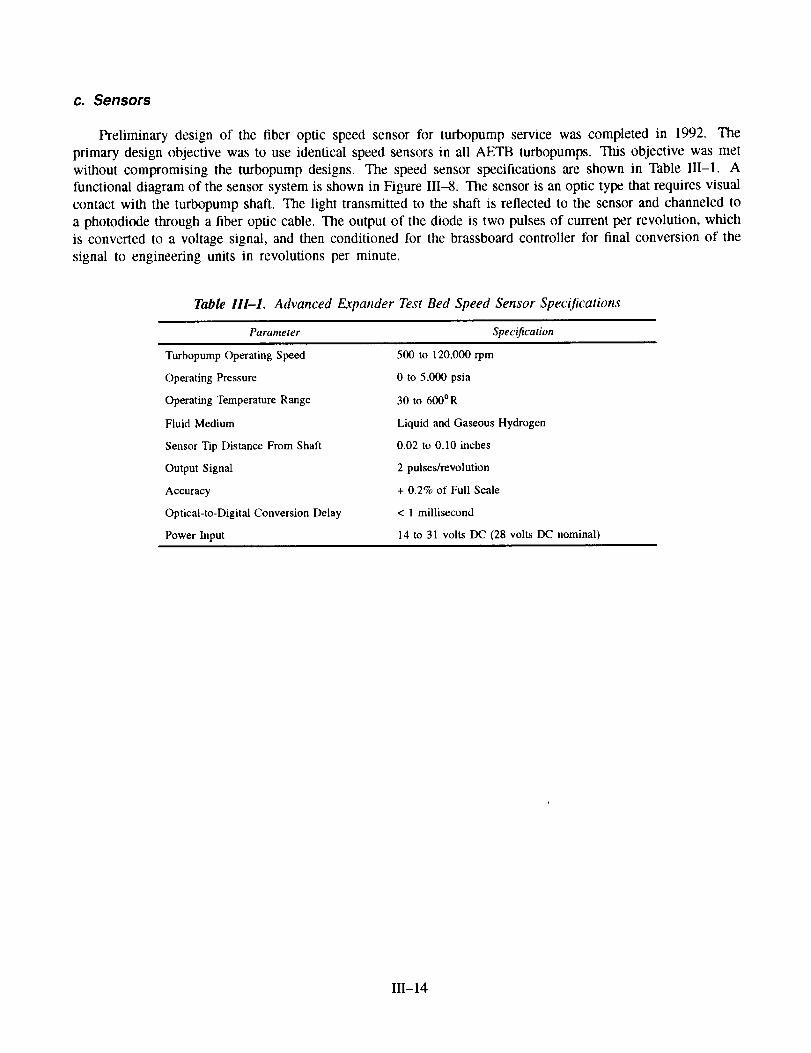
Preliminary design of the fiber optic speed sensor for turbopump service was completed in 1992. The
primary design objective was to use identical speed sensors in all AETB turbopumps. This objective was metwithout compromising the turbopump designs. The speed sensor specifications are shown in Table III-1. A
functional diagram of the sensor system is shown in Figure III-8. The sensor is an optic type that requires visual
contact with the turbopump shaft. The light transmitted to the shaft is reflected to the sensor and channeled to
a photodiode through a fiber optic cable. The output of the diode is two pulses of current per revolution, which
is converted to a voltage signal, and then conditioned for the brassboard controller for final conversion of the
signal to engineering units in revolutions per minute.
Table 111-1. Advanced Expander Test Bed Speed Sensor Specifications
Parameter Specification
Turbopump Operating Speed
Operating Pressure
Operating Temperature Range
Fluid Medium
Sensor Tip Distance From Shaft
Output Signal
Accuracy
Optical-to-Digital Conversion Delay
Power Input
500 to 120,000 rpm
0 to 5,000 psia
30 to 600°R
Liquid and Gaseous Hydrogen
0.02 to 0.10 inches
2 pulses/revolution
+ 0.2% of Full Scale
< 1 millisecond
14 to 31 volts DC (28 volts DC nominal)
Ili-14

F ii-
._
>
('dvii
0
>
b
I,,.
°_
111-15

5. Hydrogen Mixer
The detailed drawings of the mixer have been completed.
In the split expander cycle, the hydrogen mixer, shown in Figure III-9, mixes the warm hydrogen from
the turbines with the cold hydrogen from the l st-stage fuel pump discharge. The combined flow then enters
the main combustor chamber injector fuel manifold. Good mixing of these streams is critical to maintaining
stable combustion and uniform flow through the individual fuel elements. At the design point, the flow into the
mixer is split between the hot and cold lines. The cold hydrogen flow is controlled by means of the FJBV. The
percent of cold flow bypassed is lower at lower throttle conditions. For instance, at 20-percent thrust, the FJBV
is completely closed so all the flow into the mixer is the warm hydrogen from the turbines. When bypassing
cold flow to the mixer, the mixer must effectively mix the hot and cold hydrogen, yet minimize system pressure
loss. To achieve the required mixing performance, the AETB will use an in-line mixer similar to the one used
by the Space Shuttle Main Engine (SSME) system. The mixer works on the same principle as a jet pump, i.e., a
high velocity stream imparts momentum to a lower velocity stream. The momentum transfer creates turbulence
which promotes mixing of the two streams.
Hot Hydrogen from
Turbine Discharge
Cold Hydrogen from
Jacket Bypass Valve -_
/
Centralizes Tube
at Assembly
Fit Tightens at Operating
Temperatures to Support Tube
and Damp Any Vibrations
Figure HI-9. Hydrogen Mixer
111-16

Thehothydrogenfromtheturbinedischargeformsthehigh-velocitystreamwhilethecoldhydrogenfromthepumpis thelow-velocitystream.UsingtheestablisheddesignprocedureIbrjet pumps,theminimummixinglengthfor themaximumjet pumpefficiencywascalculatedto be10inchesfor theAETBdesignat worstcaseoperatingconditions.Giventheoverallmixinglengthof 37inchesandtherelativelyhighmomentumratioof28betweenstreams,theAETBmixerdesignis conservativeandwill provideuniformflowto theinjector.
Themixerdesignincorporatesthefollowingfeatures:
A two-piececonstructionthatnearlyeliminatesthethermalstressproblemsthatwereevidentwithanearlierwelded,one-piecedesign.
• A separate piece of hardware for the hot inflow that provides the versatility of changing mixer
geometry to evaluate alternative mixer designs.
Parts that are machined entirely from 300 series stainless steel using only conventional machining
techniques.
• Repairability that is built into the design by allowing enough radial clearance around all tapped holes
for threaded insert repairs.
• A conservative LCF that exceeds 3000 thermal cycles.
• A cantilevered tube natural frequency of 3300 Hz. This is well below either pump rotor vibration
modes and well above the low energy vortex shedding frequency of 66 Hz.
6. System Integration
Under the system integration task, all propellant lines and component supports are being designed, and the
various components are being integrated into the test bed configuration.
There was no engineering effort in this area during the year.
D. TASK 8.0 -- TECHNICAL ASSISTANCE
Under Task Order 2, RL10 start-up and shutdown transient data were provided to NASA-LeRC along with
updated valve sequencing. Additional RL10 design and test data were also provided for use in formulating a
specific ROCETS model for the RL10 and to verify the ROCETS code. Specific items provided were:
• Current production turbine performance data
• Chamber/nozzle heat transfer design characteristics
• Steady-state and transient test data from a recent production engine
• A reference for the full range pump map methodology
• Documentation for the RL10 cool down model
• Correlations for pump internal leakage flows.
Ili-17

SECTION IVCURRENT PROBLEMS AND FUTURE WORK
No technical problems have been encountered that would prevent meeting the milestones shown in theAdvanced Expander Test Bed (AETB) Program Schedule in Section II.
Contract work planned for 1993 includes:
• Complete and obtain final approval of the layout of the oxidizer turbopump so that preparation of
detailed drawings can be initiated in 1993.
• Complete the hydrogen turbopump layout to support a formal design review in second quarter 1993.
• Design the tubular AETB nozzle extension.
• Receive the three valves placed on early procurement to support tests of the Pratt & Whitney (P&W)thrust chamber rig.
• Design the control and engine system and hold a System Critical Design Review in November 1993.
• Fabricate the mixer.
• Test the P&W injector and milled channel combustion chamber in a NASA test facility.
IV-1

![Expander 符号生成行列、パリティ検査行列、Tanner グラフ expander 符号 expander グラフ [Sipser-Spieleman ‘96] expander 符号の構成 bit-flipping 復号法](https://img.pdfslide.us/doc/110x75/5f0bdbc37e708231d4328ff6/expander-c-ceoefffoeeoetanner-ff-expander.jpg)